

Page 1
INSTRUCTION MANUAL
VHF TRANSCEIVER
iF15/S
UHF TRANSCEIVER
iF25/S
Page 2

FOREWORD
WORD DEFINITION
RWARNING
Personal injury, fire hazard or electric shock
may occur.
NOTE
If disregarded, inconvenience only. No risk
of personal injury, fire or electric shock.
CAUTION
Equipment damage may occur.
READ ALL INSTRUCTIONS carefully and completely before
using the transceiver.
SAVE THIS INSTRUCTION MANUAL— This instruction
manual contains important operating instructions for the IC-F15/
VHF TRANSCEIVER
F15S
and IC-F25/F25S
UHF TRANSCEIVER
EXPLICIT DEFINITIONS
OPERATING NOTES
• When transmitting with a portable radio, hold the radio in a vertical
position with its microphone 5 to 10 centimeters away from your
mouth. Keep the antenna at least 2.5 centimeters from your head
and body.
• If you wear a portable two-way radio on your body, ensure that the
antenna is at least 2.5 centimeters from your body when transmitting.
i
.
Page 3

PRECAUTION
R WARNING! NEVER hold the transceiver so that the antenna
is very close to, or touching exposed parts of the body, especially
the face or eyes, while transmitting. The transceiver will perform
best if the microphone is 5 to 10 cm away from the lips and the
transceiver is vertical.
R WARNING! NEVER operate the transceiver with a headset
or other audio accessories at high volume levels.
CAUTION! NEVER short the terminals of the battery pack.
NEVER connect the transceiver to a power source other than the
BP-230, BP-231 or BP-232. Such a connection will ruin the transceiver.
DO NOT push the PTT when not actually desiring to transmit.
AVOID using or placing the transceiver in direct sunlight or in
areas with temperatures below –25°C or above +55°C.
DO NOT modify the transceiver for any reason.
MAKE SURE the flexible antenna and battery pack are securely
attached to the transceiver, and that the antenna and battery pack
are dry before attachment. Exposing the inside of the transceiver
to water will result in serious damage to the transceiver.
The use of non-Icom battery packs/chargers may impair transceiver
performance and invalidate the warranty.
Icom, Icom Inc. and the logo are registered trademarks of Icom Incorporated (Japan) in the United States, the United Kingdom, Germany, France, Spain,
Russia and/or other countries.
ii
Page 4

TABLE OF CONTENTS
FOREWORD ……………………………………………………………… i
EXPLICIT DEFINITIONS ………………………………………………… i
OPERATING NOTES……………………………………………………… i
PRECAUTION …………………………………………………………… ii
TABLE OF CONTENTS ………………………………………………… iii
1 ACCESSORIES ……………………………………………………… 1–5
‘ Supplied accessories………………………………………………… 1
‘ Accessory attachments……………………………………………… 2
2 PANEL DESCRIPTION …………………………………………… 6–11
‘ Front, top and side panels ………………………………………… 6
‘ LED indicator ………………………………………………………… 8
‘ Programmable function keys ……………………………………… 9
3 CONVENTIONAL OPERATION ………………………………… 12–18
‘ Turning power ON ………………………………………………… 12
‘ Channel selection ………………………………………………… 12
‘ Call procedure ……………………………………………………… 13
‘ Receiving and transmitting ……………………………………… 14
‘ Scrambler function ………………………………………………… 16
‘ Setting the squelch level ………………………………………… 16
‘ Man Down Emergency Call ……………………………………… 17
4 OPTIONAL UNIT INSTALLATION……………………………… 18–19
‘ Optional unit installation …………………………………………… 18
‘ Scrambler unit installation ………………………………………… 19
5 BATTERY CHARGING ………………………………………… 20–25
‘ Battery charging …………………………………………………… 20
‘ Caution ……………………………………………………………… 21
‘ Optional battery chargers ………………………………………… 22
6 SWIVEL BELT CLIP……………………………………………… 26–29
‘ MB-93 contents …………………………………………………… 26
‘ To attach …………………………………………………………… 26
‘ To detach …………………………………………………………… 28
7 OPTIONS ………………………………………………………… 30–31
8 DOC………………………………………………………………… 32–33
iii
Page 5
ACCESSORIES
qw
r
e
t
1
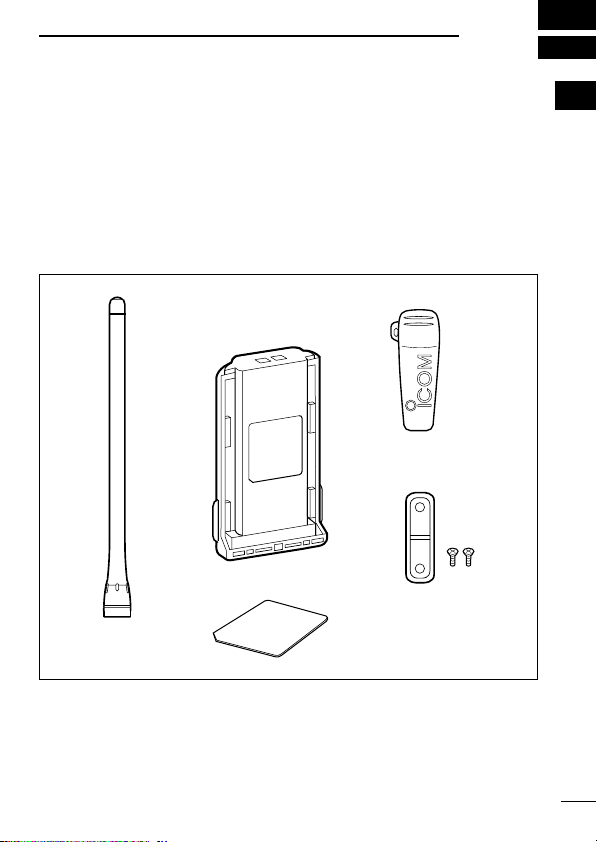
■ Supplied accessories
The following accessories are supplied: Qty.
q Flexible antenna . . . . . . . . . . . . . . . . . . . . . . . . . . . . . . . . . . . .1
w Battery pack . . . . . . . . . . . . . . . . . . . . . . . . . . . . . . . . . . . . . . .1
e Belt clip . . . . . . . . . . . . . . . . . . . . . . . . . . . . . . . . . . . . . . . . . . .1
r Unit cover (double-sided tape)* . . . . . . . . . . . . . . . . . . . . . . . .1
t Jack cover (with screws) . . . . . . . . . . . . . . . . . . . . . . . . . . .1 set
* Use the unit cover as a spare. Ask your dealer for details.
1
1
Page 6

ACCESSORIES
1
■ Accessory attachments
D Flexible antenna
Connect the supplied flexible antenna to the antenna connector.
CAUTION:
• NEVER HOLD by the antenna
when carrying the transceiver.
• Transmitting without an antenna
may damage the transceiver.
2
Page 7
ACCESSORIES
q
w
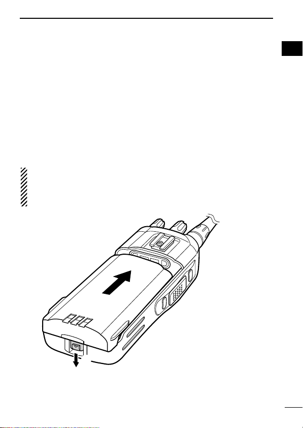
ï Battery pack
To attach the battery pack:
Slide the battery pack on the back of the transceiver in the direction of the arrow (q), then lock it with the battery release button.
• Slide the battery pack until the battery release button makes a ‘click’
sound.
To release the battery pack:
Push the battery release button in the direction of the arrow (w) as
shown below. The battery pack is then released.
NEVER release or attach the battery pack when the transceiver
is wet or soiled. This may result in water or dust getting into the
transceiver/battery pack and may result in the transceiver being
damaged.
1
1
3
Page 8
ACCESSORIES
w
w
q
q
q
w
1
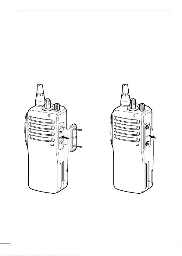
ï Jack cover
Attach the jack cover when the optional speaker-microphone is not
used.
To attach the jack cover:
q Attach the jack cover to the
[SP MIC] connector.
w Tighten the screws.
To detach the jack cover:
q Unscrew the screws with a
phillips screwdriver.
w Detach the jack cover for the
speaker-microphone connection.
4
Page 9
ACCESSORIES
q
w
1
D Belt clip
To attach the belt clip:
q Release the battery pack if it is attached.
w Slide the belt clip in the direction of the arrow until the belt clip is
locked and makes a ‘click’ sound.
To detach the belt clip:
q Release the battery pack if it is attached.
w Pinch the clip (q), and slide the belt clip in the direction of the
arrow (w).
1
5
Page 10
2
r
q
w
y
u
i
e
Microphone
Speaker
t
IC-F15S/F25S IC-F15/F25
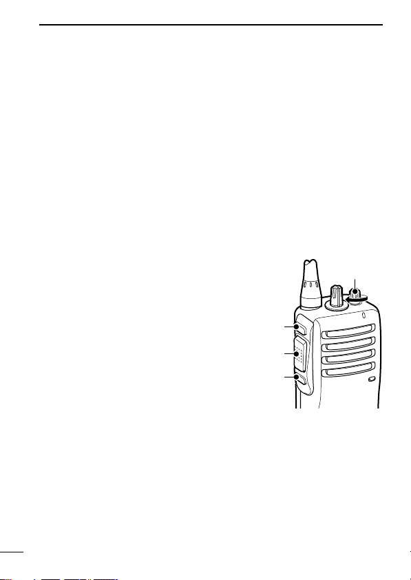
PANEL DESCRIPTION
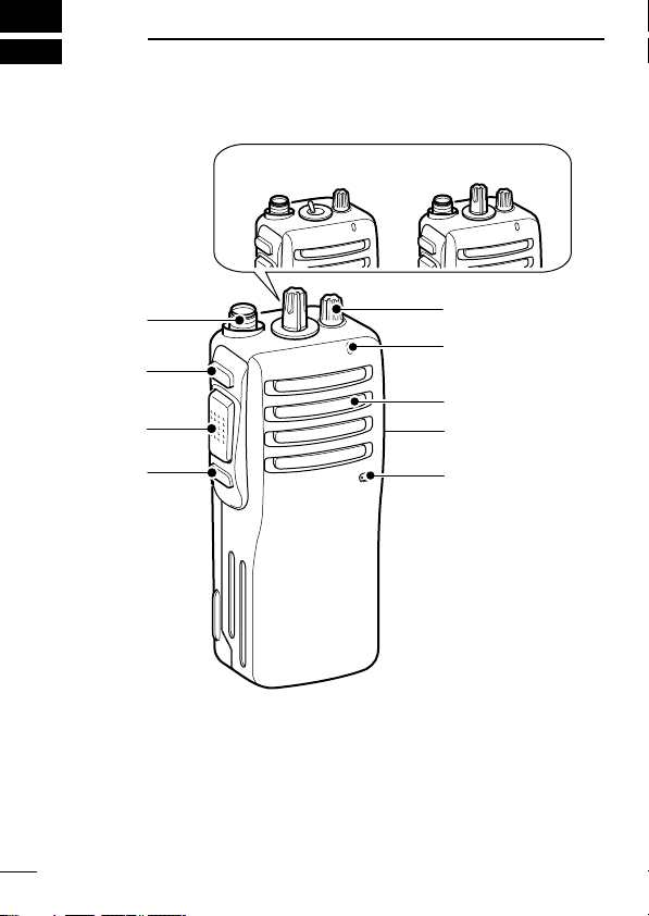
■ Front, top and side panels
q CHANNEL SW/SELECTOR
• IC-F15S/F25S: Toggle the channel switch to select the pre-programmed channel 1 or 2.
• IC-F15/F25 : Rotate the channel selector to select the preprogrammed memory channels.
w VOLUME CONTROL [VOL]
Rotate to turn the power ON/OFF and adjust the audio level.
6
Page 11
PANEL DESCRIPTION
Upper
Lower
[SP MIC] jack cover
NOTE: Attach the [SP MIC] jack
cover when the optional speaker-microphone is not used. (p. 4)
2
e LED INDICATOR (p. 8)
➥ Lights red while transmitting.
➥ Lights green while receiving a signal, or when the squelch is
open.
➥ Lights/blinks orange when the matched 2/5-tone code is re-
ceived, according to the pre-programming.
r SPEAKER-MICROPHONE CONNECTOR [SP MIC]
Connects the optional speaker-microphone. (p. 31)
t DEALER-PROGRAMMABLE KEY [Lower]
The desired function can be assigned by your dealer. (p. 9)
y PTT SWITCH [PTT]
Push and hold to transmit; release to receive.
u DEALER-PROGRAMMABLE KEY [Upper]
The desired function can be assigned by your dealer. (p. 9)
i ANTENNA CONNECTOR
Connects the supplied antenna.
DD
Programmable key reference
2
7
Page 12
PANEL DESCRIPTION
R R R R
O O
O O
G G G G
G G
R O R O R O R O R O R O R O R O
G
G G
R
2
‘‘
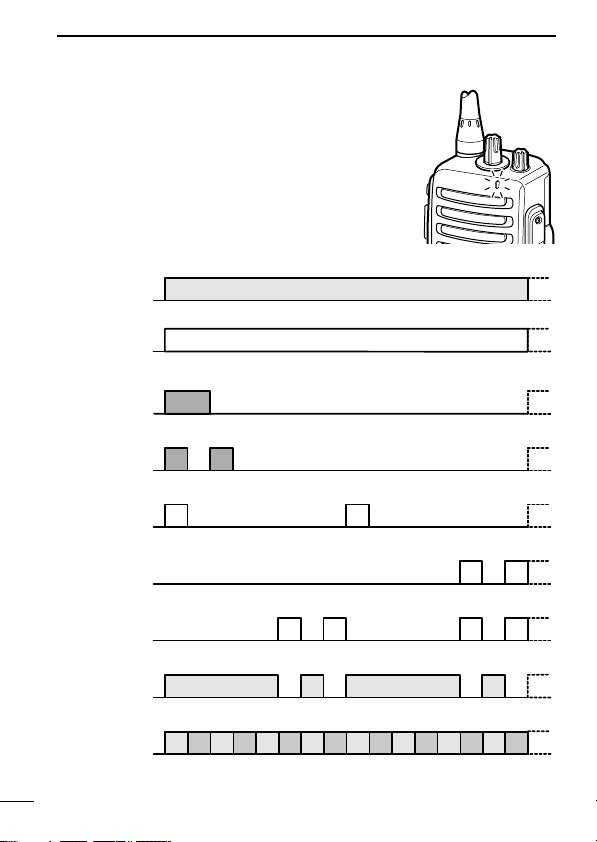
LED indicator
The LED indicator indicates several information as follows;
(Ref.; R=Red, G=Green, O=Orange)
• TX: Turns Red while transmitting a signal.
• RX: Turns Green while receiving a signal.
• Call LED (ON): When receiving a matched 2/5-tone.
• Call LED (Blink): When receiving a matched 2/5-tone.
• Fast/Slow scan: Blinks while Fast/Slow scan is activated.
• Low BATT1: You should charge the battery. (blinks slowly)
• Low BATT2: You must charge the battery. (blinks fast)
• TX low BATT2: Low BATT2 was detected during TX mode.
• CH err: Non-programmed channel is selected.
8
Page 13

PANEL DESCRIPTION
‘‘
Programmable function keys
The following functions can be assigned to [Upper] and [Lower]
programmable function keys.
Consult your Icom dealer or system operator for details concerning
your transceivers programming.
If the programmable function names are bracketed in the following
explanations, the specific key used to activate the function depends
on programming.
SCAN A KEY
➥ This key’s operation depends on the Power ON Scan setting.
When the power ON scan function is turned OFF;
Push to start and cancel scanning operation. In case of transmission during scan, cancels scanning.
When the power ON scan function is turned ON;
Push to pause scanning. Scanning resumes after passing a
specified time period. In case of transmission during scan,
pauses scanning. Scanning resumes after passing a specified
time period.
SCAN B KEY
Push to start and cancel scanning operation. In case of transmission during scan, pauses scanning. Scanning resumes after passing a specified time period.
PRIORITY CHANNEL KEYS
➥ Push to select the Priority A or Priority B channel.
➥ Push and hold [Prio A (Rewrite)] to rewrite the Prio A channel.
MR-CH 1/2/3/4 KEYS
Push to select a memory channels 1 to 4 directly.
NOTE: The memory channels 3 and 4 are available for ICF15S/F25S when [MR-CH 3] and [MR-CH 4] keys are assigned.
2
2
9
Page 14

PANEL DESCRIPTION
2
MONITOR KEY
➥ Mute and release the CTCSS (DTCS) or 2-tone squelch mute.
Open any squelch/deactivate any mute while pushing this key.
(LMR operation only)
➥ Activates one of (or two of) the following functions on each chan-
nel independently: (PMR operation only)
• Push and hold to un-mute the channel (audio is emitted; ‘Audible’
condition).
• Push to mute the channel (sets to ‘Inaudible’ only).
• Push to un-mute the channel (sets to ‘Audible’ only).
• Push after the communication is finished to send a ‘reset code’.
NOTE: The un-mute condition (‘Audible’ condition) may automatically return to the mute condition (‘Inaudible‘ condition)
after a specified period.
LOCK KEY
Push and hold to electronically lock all programmable keys except
the following:
[Call] (incl. Call A and Call B), [Moni(Audi)] and [Emergency] keys.
OUTPUT POWER SELECTION KEY
Select the transmit output power temporarily or permanently, depending on the pre-setting.
• Ask your dealer for the output power level for each selection.
TALK AROUND KEY
➥ Push to turn the talk around function OFF.
➥ Push and hold to turn the talk around function ON.
• The talk around function equalizes the transmit frequency to the receive frequency for transceiver-to-transceiver communication.
WIDE/NARROW KEY
➥ Push to select the IF bandwidth to wide.
• The wide passband width can be selected from 25.0 or 20.0 kHz
using the CS-F14
your dealer for details.
CLONING SOFTWARE
(PMR operation only.) Ask
➥ Push and hold to select the IF bandwidth to narrow.
10
Page 15

PANEL DESCRIPTION
DTMF AUTODIAL KEY
Push to transmit the programmed DTMF code.
CALL KEYS
Push to transmit a 2/5-tone code.
• Call transmission is necessary before you call another station depending on your signalling system.
• [Call A] and/or [Call B] keys may be available when your system em-
ploys selective ‘Individual/Group’ calls. Ask your dealer which call is
assigned to each key.
EMERGENCY KEYS
➥ Push and hold to transmit an emergency call.
➥ When [Emergency Single (Silent)] or [Emergency Repeat
(Silent)] is pushed, an emergency call is transmitted without a
beep emission.
• If you want to cancel the emergency call, push (or push and hold)
the key again before transmitting the call.
• The emergency call is transmitted one time only or repeatedly until
receiving a control code depending on the pre-setting.
VOICE SCRAMBLER FUNCTION KEYS
➥ Push to turn the voice scrambler function OFF.
➥ Push and hold to turn the voice scrambler function ON.
OPT OUT KEYS
➥ Push to inactivate the connected output signal level.
➥ Push and hold to activate the connected output signal level.
SIREN KEY
Push to emit a siren. This function can be used for situations other
than an emergency alert such as a security alarm for example.
2
2
11
Page 16

3
[VOL]
[CHANNEL
SELECTOR]
[CHANNEL SWITCH]
CONVENTIONAL OPERATION
■ Turning power ON
➥ Rotate [VOL] to turn power ON.
■ Channel selection
IC-F15S/F25S:
Toggle [CHANNEL SWITCH] to select
the channel 1 or 2, or, push one of [MR-
CH 1] to [MR-CH 4] key to select a channel directly.
• The memory channels 3 and 4 are available when [MR-CH 3] and [MR-CH 4]
keys are assigned.
IC-F15/F25:
Rotate [CHANNEL SELECTOR] to select the desired operating channel, in sequence; or, push one of [MR-CH 1] to
[MR-CH 4] key to select a channel directly.
AUTOMATIC SCAN TYPE:
Channel setting is not necessary for this type. When turning the
power ON, the transceiver automatically starts scanning. Scanning
stops when receiving a call.
12
Page 17

CONVENTIONAL OPERATION
Selective calling
Non-selective calling
■ Call procedure
When your system employs tone signalling (excluding CTCSS and
DTCS), the call procedure may be necessary prior to voice transmission. The tone signalling employed may be a selective calling
system which allows you to call specific station(s) only and prevent
unwanted stations from contacting you.
q Select the desired TX code channel or 2/5-tone code according
to your System Operator’s instructions.
• This may not be necessary depending on programming.
w Push the call key (assigned to one of the dealer programmable
keys.) (p. 11)
e After transmitting a 2/5-tone code, the remainder of your com-
munication can be carried out in the normal fashion.
3
3
13
Page 18

CONVENTIONAL OPERATION
3
■ Receiving and transmitting
NOTE: Transmitting without an antenna may damage the trans-
ceiver. See p. 2 for antenna attachment.
Receiving:
q Rotate [VOL] to turn power ON.
w Toggle [CHANNEL SWITCH] (IC-F15S/F25S), rotate [CHAN-
NEL SELECTOR] (IC-F15/F25) or push one of [MR-CH 1] to
[MR-CH 4] key to select a channel.
For IC-F15S/F25S
The memory channels 3 and 4 are available when [MR-CH 3]
and [MR-CH 4] keys are assigned.
e When receiving a call, adjust the audio output level to a comfort-
able listening level.
Transmitting:
Wait for the channel to become clear to avoid interference.
q While pushing and holding [PTT], speak into the microphone at
a normal voice level.
• When a tone signalling system is used, the call procedure described on p. 13 may be necessary.
w Release [PTT] to return to receive.
IMPORTANT!: To maximize the readability of your signal;
1. Pause briefly after pushing [PTT].
2. Hold the microphone 5 to 10 cm from your mouth, then speak
into the microphone at a normal voice level.
:
14
Page 19

CONVENTIONAL OPERATION
D Transmitting notes
• Transmit inhibit function
The transceiver has several inhibit functions which restrict transmission under the following conditions:
- The channel is in mute condition.
- Channel is busy.
- Un-matched (or matched) CTCSS is received.
- The selected channel is a ‘receive only’ channel.
• Time-out timer
After continuous transmission for the pre-programmed time period,
the time-out timer activates, and causes the transceiver to stop
transmitting.
• Penalty timer
Once the time-out timer activates, transmission is further inhibited
for a period determined by the penalty timer.
D DTMF transmission
If the transceiver has [DTMF Autodial] assigned to it, the automatic
DTMF transmission function is available.
➥ Push [DTMF Autodial] to transmit the DTMF code.
3
3
15
Page 20
CONVENTIONAL OPERATION
[VOL]
[Upper]
[Lower]
[PTT]
3
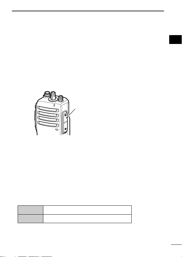
■ Scrambler function
The optional voice scrambler units UT-109 (#01) and UT-110 (#01)
provide high performance private communication between stations
with the same scrambler codes.
➥ Push and hold [Scrambler] to turn the scrambler function ON.
➥ Push [Scrambler] to turn the scrambler function OFF.
■ Setting the squelch level
The squelch circuit mutes the received audio signal depending on
the signal strength.
q While pushing [PTT] and [Lower],
rotate [VOL] to turn the power ON
to enter the squelch level adjustment mode.
w Push [Upper] to increase the
squelch level (tight squelch) or
[Lower] to decrease the squelch
level (loose squelch).
e Rotate [VOL] to turn the power
OFF to fix the squelch level.
16
Page 21

CONVENTIONAL OPERATION
■ Man Down Emergency Call
The man down emergency call function transmits an emergency
call automatically, after the transceiver laying down in a horizontal
position for a pre-set time period. (The optional UT-113
UNIT
is required.)
After the emergency call, the transceiver performs transmission and
reception alternately with the following conditions:
- Transmits the microphone signals.
- Receives the signal and emits audio.
When the emergency cancel code is received, the function is cancelled.
IMPORTANT!: Set an emergency channel individually, to provide
certain emergency call operation is recommended.
MAN DOWN
3
3
17
Page 22

4
*This illustration is
described with the
UT-110.
OPTIONAL UNIT INSTALLATION
■ Optional unit installation
Install the optional unit as follows:
q Rotate [VOL] to turn the power OFF, and remove the battery
pack. (p. 3)
w Remove the unit cover.
NOTE: Use a flat head screw driver or a similar flat instrument, and insert into the hollow of the chassis, then lift and
take away the unit cover. (The removed cover cannot be used
again.)
e Install the unit as shown below.
r Replace the unit cover and the battery pack, then rotate [VOL] to
turn the power ON.
NOTE: The optional UT-109/UT-110
some PC board modifications. Please refer to the additional installation as at right.
18
SCRAMBLER UNITS
requires
Page 23

OPTIONAL UNIT INSTALLATION
■ Scrambler unit installation
The following PC board modification is required when installing the
optional UT-109 or UT-110.
q Rotate [VOL] to turn the power OFF, and remove the battery
pack. (p. 3)
w Remove the unit cover as shown at left (Optional unit installation.)
e Cut the pattern on the PCB at the TX mic circuit (MIC) and RX
AF circuit (DISC) as shown below.
r Install the scrambler unit as shown at left (Optional unit installa-
tion.)
t Replace the unit cover and the battery pack, then rotate [VOL] to
turn the power ON.
4
4
NOTE: When uninstalling the
scrambler unit
Be sure to re-solder the disconnected points at left, otherwise no
TX modulation or AF output is
available.
19
Page 24

5
BATTERY CHARGING
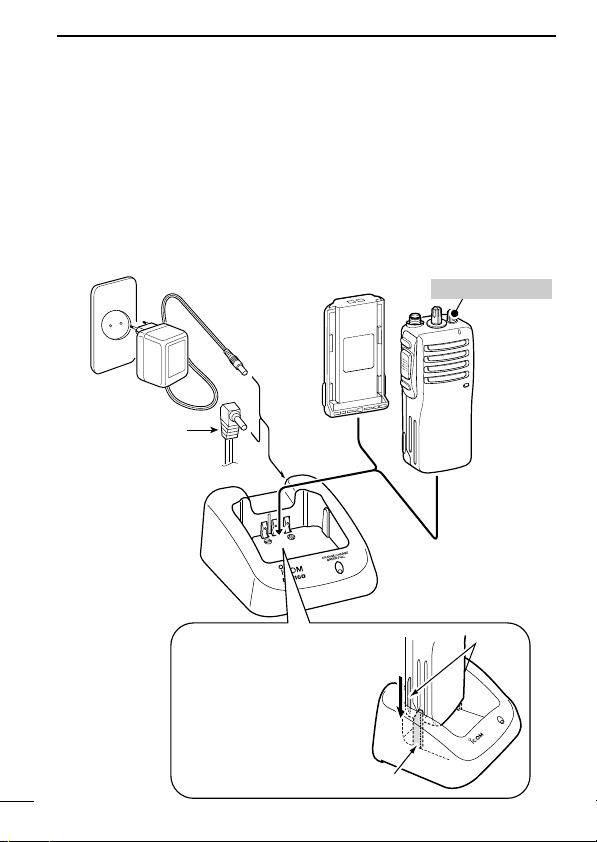
■ Battery charging
Prior to using the transceiver for the first time, the battery pack must
be fully charged for optimum life and operation.
CAUTION: To avoid damage to the transceiver, turn it OFF while
charging.
• Recommended temperature range for charging:
+10°C to +40°C
- The Li-Ion battery functions within –20°C to +60°C
• Use the specified chargers (BC-119N, BC-121N and BC-160).
NEVER use another manufacturer’s charger.
• Use the optional AC adapter. NEVER use another manufacturer’s
AC adapter.
Recommendation:
Charge the supplied battery pack for a maximum of up to
10 hours. Li-Ion batteries are different from Ni-Cd batteries in
that it is not necessary to completely charge and discharge them
to prolong the battery life. Therefore, charging the battery in intervals, and not for extended periods is recommended.
20
Page 25

BATTERY CHARGING
■ Caution
R DANGER Charge the specified Icom batteries only.
Only tested and approved for use with genuine Icom batteries. Fire
and/or explosion may occur when a third party battery pack or
counterfeit product is charged.
CAUTION! NEVER insert battery pack/transceiver (with the bat-
tery pack attached) with wet or soiled into the charger. This may result in corrosion of the charger terminals or damage to the charger.
The charger is not waterproof and water can easily get into it.
NEVER incinerate used battery packs. Internal battery gas may
cause an explosion.
NEVER immerse the battery pack in water. If the battery pack be-
comes wet, be sure to wipe it dry immediately (particularly the battery terminals) BEFORE attaching it to the transceiver. Otherwise,
the terminals will become corroded, or cause connection failure,
etc.
NEVER short the terminals of the battery pack. Also, current may
flow into nearby metal objects, such as a necklace, etc. Therefore,
be careful when carrying with, or placing near metal objects, carrying in handbags, etc.
AVOID leaving the battery pack in a fully charged, or completely
discharged condition for long time. It causes shorter battery life. In
case of leaving the battery pack unused for a long time, it must be
kept safely after discharge, or use the battery until the battery indicator appears, then remove it from the transceiver.
If your battery pack seems to have no capacity even after being
charged, fully charge the battery pack again. If the battery pack still
does not retain a charge (or very little), a new battery pack must be
purchased.
5
5
21
Page 26
BATTERY CHARGING
AC adapter
(Not supplied with
some versions.)
Optional OPC-515L
(for 13.8 V power
source) or CP-17L
(for 12 V cigarette
lighter socket) can
be used instead of
the AC adapter.
Battery pack
Transceiver
Turn power OFF
b
c
-16
0
IMPORTANT!:
Ensure the guide lobs
on the battery pack are
correctly aligned with
the guide rails inside
the charger adapter.
Guide rail
Lobs
5
■ Optional battery chargers
D Rapid charging with the BC-160
The optional BC-160 provides rapid charging of optional Li-Ion battery packs.
• An AC adapter (may be supplied with BC-160 depending on version) or the DC power cable (OPC-515L/CP-17L) is additionally
required.
22
Page 27

BATTERY CHARGING
AD-106
Connectors
Plugs
Screws supplied
with the charger
adapter
ï AD-106 installation
q Install the AD-106 desktop charger adapter into the holder space
of the BC-119N/121N.
w Connect the plugs of the BC-119N/BC-121N to the AD-106 with
the connector, then install the adapter into the charger with the
supplied screws.
5
5
23
Page 28

BATTERY CHARGING
AD-106 charger
adapter is installed in BC-119N.
AC adapter
(Not supplied with
some versions.)
Optional OPC-515L
(for 13.8 V power
source) or CP-17L
(for 12 V cigarette
lighter socket) can
be used instead of
the AC adapter.
Battery pack
Transceiver
Turn power OFF
IMPORTANT!:
Ensure the guide
lobs on the battery
pack are correctly
aligned with the
guide rails inside
the charger adapter.
Lobs
Guide rails
5
D Rapid charging with the BC-119N+AD-106
The optional BC-119N provides rapid charging of optional Li-Ion
battery packs.
The following items are additionally required:
• One AD-106
• An AC adapter (may be supplied with BC-119N depending on version) or the DC power cable (OPC-515L/CP-17L).
(purchase separately).
24
Page 29

BATTERY CHARGING
AC adapter
(Purchased
separately)
AD-106 charger
adapters are installed
in each slot.
DC power cable
(OPC-656)
(Connect with the
DC power supply;
13.8 V/at least 7 A)
Battery pack
Transceiver
Turn power OFF
IMPORTANT!:
Ensure the guide
lobs on the battery pack are
correctly aligned
with the guide
rails inside the
charger adapter.
Guide rails
Lobs
D Rapid charging with the BC-121N+AD-106
The optional BC-121N allows up to 6 battery packs to be charged
simultaneously. The following items are additionally required.
• Six AD-106.
• An AC adapter (BC-157) or the DC power cable (OPC-656)
5
5
25
Page 30
6
q w
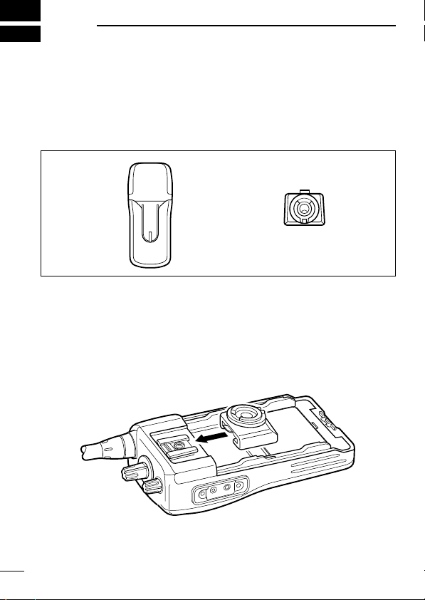
SWIVEL BELT CLIP
■ MB-93 contents
Qty.
q Belt clip …………………………………………………………… 1
w Base clip …………………………………………………………… 1
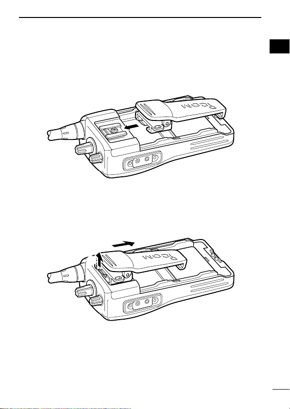
■ To attach
q Release the battery pack if it is attached. (p. 3)
w Slide the base clip in the direction of the arrow until the base clip
is locked and makes a ‘click’ sound.
26
Page 31

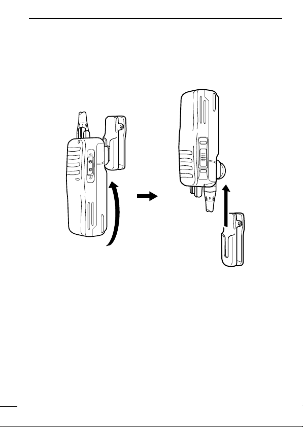
SWIVEL BELT CLIP
e Clip the belt clip to a part of your belt. And insert the transceiver
into the belt clip until the base clip inserted fully into the groove.
r Once the transceiver is locked in place, it swivels as illustrated
below.
6
6
27
Page 32
SWIVEL BELT CLIP
6
■ To detach
q Turn the transceiver upside down in the direction of the arrow
and pull out from the belt clip.
28
Page 33

SWIVEL BELT CLIP
q
w
w Release the battery pack if it is attached. (p. 3)
e Pinch the clip (q), and slide the base clip in the direction of the
arrow (w).
CAUTION:
HOLD THE TRANSCEIVER TIGHTLY, WHEN HANGING OR
DETACHING THE TRANSCEIVER FROM THE BELT CLIP.
Otherwise the transceiver may not be attached to the holder or
swivel properly if the transceiver is accidentally dropped and the
base clip is scratched or damaged.
6
6
29
Page 34

7
OPTIONS
D BATTERY PACK
• BP-230 Li-Ion
BATTERY PACK
7.4 V/800 mAh Li-Ion battery pack, allows approx. 5.5 hours* operation.
• BP-231
Li-Ion
BATTERY PACK
7.4 V/1150 mAh Li-Ion battery pack, allows approx. 8 hours* operation.
• BP-232
Li-Ion
BATTERY PACK
7.4 V/2000 mAh Li-Ion battery pack, allows approx. 14 hours* operation.
*Typical operation; Tx:Rx:Stand-by duty cycle=5:5:90
D CHARGERS
• BC-119N
+ BC-145
DESKTOP CHARGER
AC ADAPTER
+ AD-106
CHARGER ADAPTER
For rapid charging of battery packs. An AC adapter is supplied
with the charger depending on versions. Charging time: approx. 2
hours when BP-231 is attached.
• BC-121N
+ BC-157
MULTI-CHARGER
AC ADAPTER
+ AD-106
CHARGER ADAPTER
(6 pcs.)
For rapid charging of up to 6 battery packs (six AD-106’s are required) simultaneously. An AC adapter should be purchased separately. Charging time: approx. 2 hours when BP-231 is attached.
• BC-160
DESKTOP CHARGER
+ BC-145
AC ADAPTER
For rapid charging of battery packs. An AC adapter is supplied
with the charger depending on versions. Charging time: approx. 2
hours when BP-231 is attached.
D OPTIONAL UNITS
• UT-108
DTMF DECODER UNIT
Provides pager and code squelch capabilities.
• UT-109 (#01)/UT-110 (#01)
SCRAMBLER UNITS
Non-rolling type (UT-109)/Rolling type (UT-110) voice scrambler
unit provides higher communication security.
• UT-113
MAN DOWN UNIT
Provides a measure of safety when working in a hazardous environment, etc.
30
Page 35

OPTIONS
D BELT CLIPS
• MB-93
• MB-94
SWIVEL BELT CLIP
BELT CLIP
Exclusive alligator-type belt clip. The same as supplied with the
transceiver.
• MB-96N/96F
LEATHER BELT HANGER
D DC CABLES
• CP-17L
CIGARETTE LIGHTER CABLE
Allows charging of the battery pack through a 12 V cigarette
lighter socket. (For BC-119N)
• OPC-515L/OPC-656
DC POWER CABLES
Allows charging of the battery pack using a 13.8 V power source
instead of the AC adapter.
OPC-515L: For BC-119N
OPC-656 : For BC-121N
D OTHER OPTIONS
• SP-13
EARPHONE
Provides clear receive audio in noisy environment.
• HM-131L
SPEAKER-MICROPHONE
Combination speaker-microphone that provides convenient operation while hanging the transceiver from your belt.
HM-131L has a moisture proof construction.
• HS-94/HS-95/HS-97
HEADSET
+ VS-1L
VOX/PTT CASE
HS-94: Ear hook type HS-95: Neck-arm type
HS-97: Throat microphone
VS-1L: VOX/PTT switch box for hands-free operation, etc.
• FA-SC73US/FA-SC56VS/FA-SC57VS
STUBBY ANTENNAS
FA-SC73US: 450–490 MHz FA-SC56VS: 150–162 MHz
FA-SC57VS: 160–174 MHz
• FA-SC25U/FA-SC57U/FA-SC72U/FA-SC25V/FA-SC55V
ANTENNAS
FA-SC25U: 400–430 MHz FA-SC57U: 430–470 MHz
FA-SC72U: 470–520 MHz FA-SC25V: 136–155 MHz
FA-SC55V: 146–174 MHz
Some options may not be available in some countries. Please ask your
dealer for details.
7
7
31
Page 36

8
DECLARATION
OF CONFORMITY
We Icom Inc. Japan
1-1-32, Kamiminami, Hirano-ku
Osaka 547-0003, Japan
Kind of equipment:
VHF TRANSCEIVER
Type-designation: iC-
f15/s
Signature
Authorized representative name
Place and date of issue
Düsseldorf 30th June 2004
Declare on our sole responsibility that this equipment complies with the
essential requirements of the Radio and Telecommunications Terminal
Equipment Directive, 1999/5/EC, and that any applicable Essential Test
Suite measurements have been performed.
Version (where applicable):
0168
136 174 MHz 12.5 kHz/20 kHz/25 kHz
This compliance is based on conformity with the following harmonised
standards, specifications or documents:
i) EN 301 489-1 v1.3.1 (Sept 2001)
ii) EN 301 489-5 (August 2000)
iii) EN 60950 (August 1992+A11)
iv) EN 300 086-2 (March 2001)
v) EN 300 219-2 (March 2001)
vi) EN 300 113-2 (March 2001)
DOC
CE versions of the IC-F15/S and IC-F25/S which
display the “CE” symbol on the serial number seal,
comply with the essential requirements of the European Radio and Telecommunication Terminal Directive 1999/5/EC.
32
Page 37

This warning symbol indicates that this equipment op-
DECLARATION
OF CONFORMITY
We Icom Inc. Japan
1-1-32, Kamiminami, Hirano-ku
Osaka 547-0003, Japan
Kind of equipment:
UHF TRANSCEIVER
Type-designation: iC-
f25/s
Signature
Authorized representative name
Place and date of issue
Düsseldorf 30th July 2004
Declare on our sole responsibility that this equipment complies with the
essential requirements of the Radio and Telecommunications Terminal
Equipment Directive, 1999/5/EC, and that any applicable Essential Test
Suite measurements have been performed.
Version (where applicable):
0168
400–470 MHz 12.5 kHz/20 kHz/25 kHz
This compliance is based on conformity with the following harmonised
standards, specifications or documents:
i) EN 301 489-1 v1.3.1 (Sept 2001)
ii) EN 301 489-5 (August 2000)
iii) EN 60950 (August 1992+A11)
iv) EN 300 086-2 (March 2001)
v) EN 300 219-2 (March 2001)
vi) EN 300 113-2 (March 2001)
erates in non-harmonised frequency bands and/or may
be subject to licensing conditions in the country of use.
Be sure to check that you have the correct version of
this radio or the correct programming of this radio, to
comply with national licensing requirement.
DOC
8
8
33
Page 38

MEMO
Page 39

MEMO
Page 40
< Intended Country of Use >
GER
AUT
GBR
IRL
NOR
FRA
NED
BEL
LUX
ESP
POR
ITA
GRE
SWE
DEN
FIN
SUI
A-6370D-1EU-w
Printed in Japan
© 2004–2006 Icom Inc.
1-1-32 Kamiminami, Hirano-ku, Osaka 547-0003, Japan
 Loading...