

Page 1

CI-V REFERENCE GUIDE
HF/VHF/UHF ALL MODE
TRANSCEIVER
|705
Page 2

TABLE OF CONTENTS
REMOTE CONTROL ����������������������������������������� 2
Remote control (CI-V) information ���������������� 2
D CI-V connection ������������������������������������������������ 2
D Preparing ���������������������������������������������������������� 2
D About the data format ��������������������������������������� 2
D Command table ������������������������������������������������ 3
D Command formats ������������������������������������������ 16
• Operating frequency ����������������������������������� 16
• Operating mode ������������������������������������������ 16
• Band edge frequency settings �������������������� 16
• Duplex Offset frequency setting������������������ 16
• Codes for CW message contents ��������������� 16
• Memory content ������������������������������������������ 17
• Codes for character entries ������������������������ 18
• Band stacking register �������������������������������� 18
• Keyer memory character entries ���������������� 19
• Keyer memory content ������������������������������� 19
• IF filter width settings ���������������������������������� 19
• AGC time constant settings ������������������������ 19
• RX HPF/LPF setting for each operating mode
• SSB/SSB-DATA
transmission passband width settings �������� 19
• Split offset frequency setting����������������������� 19
• UTC Offset setting �������������������������������������� 20
• Remote MIC Key setting ����������������������������� 20
• Color settings ���������������������������������������������� 20
• Bandscope edge frequency settings ���������� 20
• Manually entered position data ������������������� 21
• D-PRS Symbol setting �������������������������������� 21
• Alarm area (Group) setting ������������������������� 21
• Data mode with filter width settings ������������ 21
• Repeater tone/tone squelch frequency
settings ������������������������������������������������������� 21
• DTCS code and polarity setting ������������������ 21
• DV Digital code squelch setting ������������������ 22
• DV MY call sign setting ������������������������������� 22
• DV TX call signs setting (24 characters)����� 22
• DV TX message setting ������������������������������ 22
• DV RX call sign data ����������������������������������� 22
• DV RX message ����������������������������������������� 23
• DV RX Status setting ���������������������������������� 23
• GPS/D-PRS data ���������������������������������������� 23
• GPS/D-PRS message �������������������������������� 25
• RIT frequency settings �������������������������������� 25
• DV TX data ������������������������������������������������� 25
• DV RX data (transceive) ����������������������������� 25
• MY position data ����������������������������������������� 25
• Selected or unselected VFO frequency
settings ������������������������������������������������������� 26
• Selected or unselected VFO’s operating
mode and filter settings ������������������������������ 26
• Scope waveform data ��������������������������������� 26
• Scope span settings
(in the Center mode Scope) ����������������������� 27
• Scope Reference level settings ������������������ 27
• Scope Fixed edge frequency settings �������� 27
��� 19
1
Page 3
REMOTE CONTROL
(see the command table)
Sub command number
(see the command table)
frequency or memory
q w e r t y u
q w e r t y u
Remote control (CI-V) information
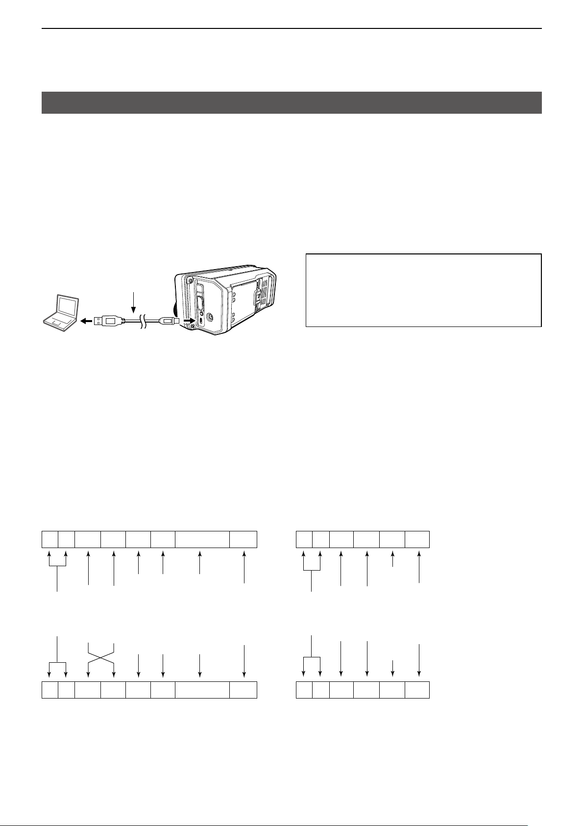
DCI-V connection
The transceiver’s operating frequency, mode, VFO and memory selection, can be remotely controlled
using a PC�
The Icom Communications Interface V (CI-V) controls the transceiver�
Connect the transceiver to a PC with a USB cable (User supplied)�
LMake the connection as short as possible� The transceiver may not be recognized by the controller, depending
on the USB cable length�
LWhen connecting to a USB port on your PC with the USB driver installed, USB (A) and USB (B) are named as
“IC-705 Serial Port A (CI-V)” and “IC-705 Serial Port B�”
PC
Right side panel
USB cable
(User supplied)
The required USB driver and driver installation guide
can be downloaded from the Icom web site�
Go to “https://www�icomjapan�com/support/,” and
then click “Firmware / Software�”
LThe download procedure on the web page may be
changed without notice�
To a USB port To the [microUSB] port
DPreparing
The Icom Communications Interface V (CI-V) is used for remote control�
To control the transceiver, first set its address, data communication speed, and transceive function�
These settings are set in the Set mode (Refer to the IC-705 instruction manual)�
DAbout the data format
The CI-V system can be written using the following data formats� Data formats differ according to
command numbers� A data area or sub command is added for some commands�
Controller to IC-705 OK message to controller
FE FE A4 E0 Cn Sc Data area FD
FE FE E0 A4 FB FD
Preamble
code (fixed)
FE FE E0 A4 Cn Sc Data area FD
Controller’s
Transceiver’s
default address
default address
Command number
BCD code data for
number entry
End of message
(fixed)
code
OK code
Preamble
code (fixed)
Controller’s
Transceiver’s
default address
default address
NG code
FE FE E0 A4 FA FD
NG message to controllerIC-705 to controller
2
(fixed)
code (fixed)
End of message
(fixed)
Page 4
REMOTE CONTROL
Remote control (CI-V) information
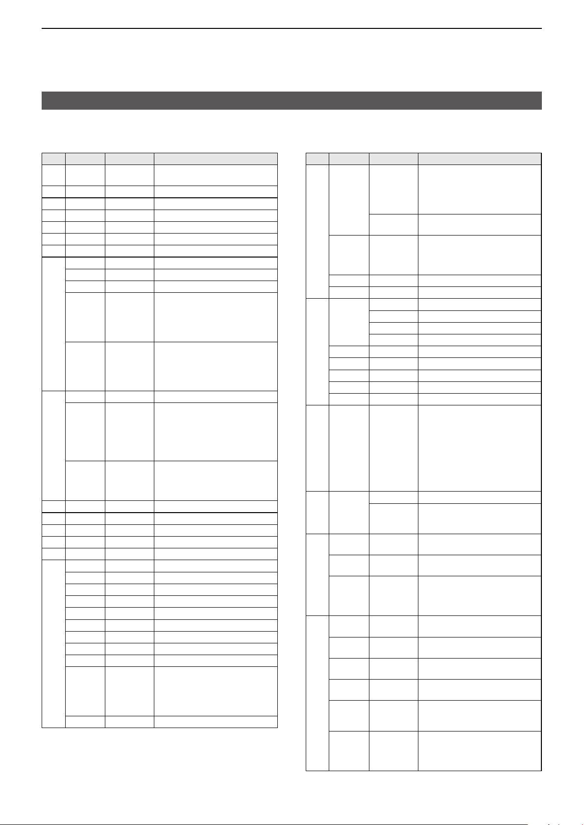
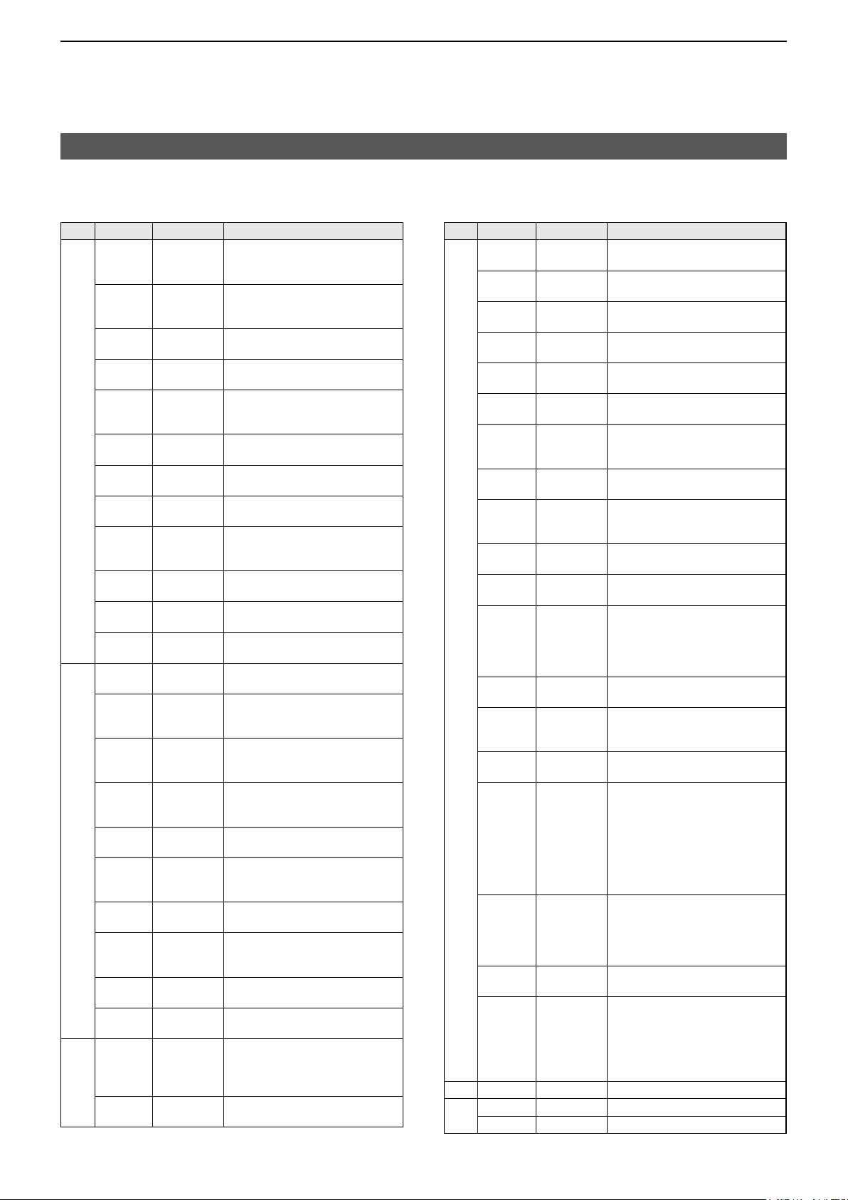
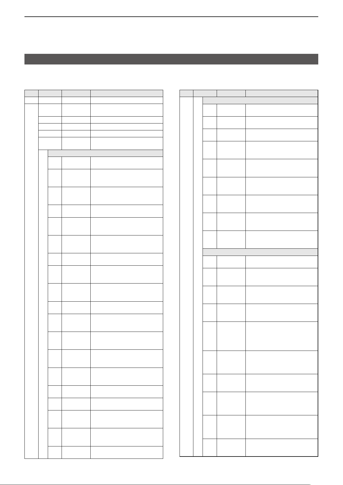
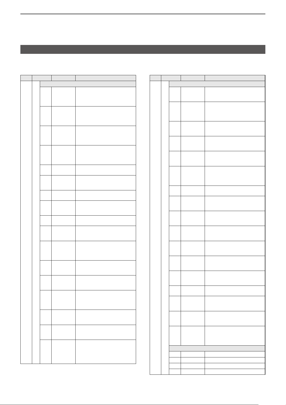
DCommand table
Cmd�
Sub cmd� Data Description
00 See p� 16� Send the frequency data
01 See p� 16� Send the mode data (transceive)
02*
03*
04*
05*
06*
1
1
1
2
2
See p� 16� Read the band edge frequencies
See p� 16� Read the operating frequency
See p� 16� Read the operating mode
See p� 16� Set the operating frequency
See p� 16� Set the operating mode
07 Select the VFO mode
00 Select VFO A
01 Select VFO B
A0 Equalize VFO A and VFO B
B0 Exchange VFO A and VFO B�
2
08*
0000 ~ 0099 Select the Memory channnel
A0 0000 ~ 0100 Select the Memory group
09 Memory write
0A Memory copy to VFO
0B Memory clear
0C*
0D*
1
2
See p� 16� Read frequency offset
See p� 16� Send frequency offset
0E 00 Cancel the scan
01 Start a Programmed/memory scan
02 Start a Programmed scan
03
12 Start a Fine programmed scan
13
22 Start a Memory scan
23 Start a Select memory scan
24 Start a Mode Select scan
2
Ax*
(x=1 ~ 7)
2
B0*
(transceive)
L When the split frequency
operation is OFF in the Memory
mode or the Call channel mode,
“FA” (NG) is returned�
L When the split frequency
operation is OFF in the Memory
mode or the Call channel mode,
“FA” (NG) is returned�
Select the Memory mode
( Memory channel: 0000 ~ 0099
Call channel: 0000 (144C1),
0001 (144C2),
0002 (430C1),
0003 (430C2))
( Memory channel group:
0000 ~ 0099
Call channel group: 0100)
Start a ∂F scan
Start a Fine ∂F scan
Select ∂F scan span
( x=1 (±5kHz), x=2 (±10kHz),
x=3 (±20kHz), x=4 (±50kHz),
x=5 (±100kHz), x=6 (±500kHz),
x=7 (±1MHz))
Clear the Select channel setting
Cmd�
Sub cmd� Data Description
0E B1*
2
Set as select channel
L The previously set number by
CI-V is set after turning power
ON, or “1” is selected if no
selection is performed�
01 ~ 03 Set the channel as a Select channel
(01=SEL1, 02=SEL2, 03=SEL3)
2
B2*
00 ~ 03 Set the Select memory scan
channel
( 00=ALL, 01=SEL1, 02=SEL2,
03=SEL3)
2
D0*
2
D3*
0F 00*
01*
11*
12*
2
00*
2
01*
2
10*
2
11*
2
12*
1
1
1
1
Set Scan resume OFF
Set Scan resume ON (Close&Delay)
Read Split OFF setting
Read Split ON setting
Read DUP– operation
Read DUP+ operation
Set Split function OFF
Set Split function ON
Set the simplex operation
Set DUP– operation
Set DUP+ operation
10* 00 ~ 13 Send/read the tuning step
( 00=OFF (10Hz or 1Hz)
01=100Hz 02=500Hz
03=1kHz 04=5kHz
05=6�25kHz 06=8�33kHz
07=9kHz 08=10kHz
09=12�5kHz 10=20kHz
11=25kHz 12=50kHz
13=100kHz)
11* 00 Send/read attenuator OFF setting
20 Send/read 20 dB attenuator setting
L You can set in the HF and
50 MHz bands�
13 00 Speech all data by voice synthesizer
(S meter level, frequency, and mode)
01 Speech the operating frequency and
S meter level by voice synthesizer
02 Speech the operating mode by voice
synthesizer
L The mode is announced after the
ongoing speech�
14* 01 0000 ~ 0255 Send/read the AF level
(0000=Minimum ~ 0255=Maximum)
02 0000 ~ 0255 Send/read the RF gain level
(0000=Minimum ~ 0255=Maximum)
03 0000 ~ 0255
Send/read the squelch level
(0000=Minimum ~ 0255=Maximum)
06 0000 ~ 0255
Send/read the NR level
(0000=0% ~ 0255=100%)
07 0000 ~ 0255 Send/read [TWIN PBT] (PBT1) position
( 0000=max� Counter Clockwise ~
0128=center ~ 0255=max� Clockwise)
08 0000 ~ 0255 Send/read [TWIN PBT] (PBT2)
position
( 0000=max� Counter Clockwise ~
0128=center ~ 0255=max� Clockwise)
3
Page 5
REMOTE CONTROL
Remote control (CI-V) information
D Command table
Cmd�
Sub cmd� Data Description
14* 09 0000 ~ 0255 Send/read CW pitch (5 Hz steps)
0A 0000 ~ 0255 Send/read the selected band’s RF
0B 0000 ~ 0255 Send/read MIC gain
0C 0000 ~ 0255 Send/read keying speed
0D 0000 ~ 0255 Send/read Notch filter setting
0E 0000 ~ 0255 Send/read the COMP level
0F 0000 ~ 0255
12 0000 ~ 0255 Send/read NB level
15 0000 ~ 0255 Send/read Monitor audio [MONI]
16 0000 ~ 0255 Send/read the VOX gain
17 0000 ~ 0255 Send/read the Anti VOX gain
19 0000 ~ 0255 Send/read LCD backlight brightness
1
01 00/01
15*
02 0000 ~ 0255 Read S-meter level
05 00/01 Read various squelch (tone squelch,
07 00/01 Read the OVF status
11 0000 ~ 0255 Read the P meter level
12 0000 ~ 0255 Read SWR meter level
13 0000 ~ 0255 Read ALC meter level
14 0000 ~ 0255 Read COMP meter level
15 0000 ~ 0255 Read V meter level
16 0000 ~ 0255 Read I meter level
16* 02 00 ~ 02 Send/read the Preamp
12 01 ~ 03 Send/read the AGC time constant
( 0000=300 Hz ~ 0128=600 Hz ~
0255=900 Hz)
power
(0000=Minimum ~ 0255=Maximum)
(0000=Minimum ~ 0255=Maximum)
(0000=6 WPM ~ 0255=48 WPM)
( 0000=max� Counter Clockwise ~
0128=center ~ 0255=max� Clockwise)
(0000=0 ~ 0255=10)
Send/read the Break-IN Delay setting
(0000=2�0d ~ 0255=13�0d)
(0000=0% ~ 0255=100%)
level
(0000=0% ~ 0255=100%)
(0000=0% ~ 0255=100%)
(0000=0% ~ 0255=100%)
(0000=0% ~ 0255=100%)
Read noise or S-meter squelch status
(00=Close, 01=Open)
( 0000=S0, 0120=S9,
0241=S9+60 dB)
and so on) status
(00=Close, 01=Open)
( 00=OVF indicator is OFF,
01=OVF indicator is ON)
(0000=0% ~ 0143=50% ~ 0213=100%)
( 0000=SWR1�0, 0048=SWR1�5,
0080=SWR2�0, 0120=SWR3�0)
(0000=Minimum ~ 0120=Maximum)
( 0000=0 dB ~ 0130=15 dB ~
0210=25�5 dB)
(0000=0 V ~ 0075=5 V ~ 0241=16 V)
(0000=0 A ~ 0121=2 A ~ 0241=4 A)
( 00=OFF, 01=P�AMP1, 02=P�AMP2)
( In the 144 or 430 MHz bands,
00=OFF, 01=ON)
(01=FAST, 02=MID, 03=SLOW)
Cmd�
Sub cmd� Data Description
16* 22 00/01 Send/read the Noise blanker
40 00/01 Send/read the Noise reduction
41 00/01 Send/read the Auto Notch function
42 00/01 Send/read the Repeater tone
43 00/01 Send/read the Tone squelch
44 00/01 Send/read the Speech compressor
45 00/01 Send/read the Monitor [MONI]
46 00/01 Send/read the VOX function
47 00 ~ 02 Send/read the BK-IN function
48 00/01
4B 00/01 Send/read the DTCS function
4F 00/01 Send/read the Twin peak filter
50 00/01 Send/read the Dial lock function
56 00/01 Send/read DSP IF filter type in the
57 00 ~ 02 Send/read the Manual Notch width
58 00 ~ 02 Send/read SSB transmit bandwidth
5B 00 ~ 02 Send/read the DSQL (Digital Call
5C 00 ~ 02 Send/read the GPS TX mode
5D 00 ~ 03,
3
17*
18 00 Turn OFF the transceiver
01*
06 ~ 09
See p� 16� Send CW messages
4
(00=OFF, 01=ON)
(00=OFF, 01=ON)
(00=OFF, 01=ON)
(00=OFF, 01=ON)
(00=OFF, 01=ON)
(00=OFF, 01=ON)
function
(00=OFF, 01=ON)
(00=OFF, 01=ON)
( 00=BK-IN OFF, 01=Semi BK-IN ON,
02=Full BK-IN ON)
Send/read the Manual Notch function
(00=OFF, 01=ON)
(00=OFF, 01=ON)
(00=OFF, 01=ON)
( Can be turned ON only when Mark
and Shift are set to 2125 Hz and
170 Hz, respectively)
(00=OFF, 01=ON)
operating band
(00=SHARP, 01=SOFT)
(00=WIDE, 01=MID, 02=NAR)
(00=WIDE, 01=MID, 02=NAR)
( One of following values is applied,
depending on the “COMP” status
(ON or OFF):
WIDE (Command: 1A 05 0017),
MID (Command: 1A 05 0018), or
NAR (Command: 1A 05 0019))
Sign squelch)/CSQL (Digital Code
squelch) setting
(DV mode only)
(00=OFF, 01=DSQL, 02=CSQL)
(00=OFF, 01=D-PRS, 02=NMEA)
Send/read the Tone squelch function
( 00=OFF, 01=TONE, 02=TSQL,
03=DTCS, 06=DTCS (T),
07=TONE (T)/DTCS (R),
08=DTCS (T)/TSQL (R),
09=TONE (T)/TSQL (R))
Turn ON the transceiver
4
Page 6
REMOTE CONTROL
Remote control (CI-V) information
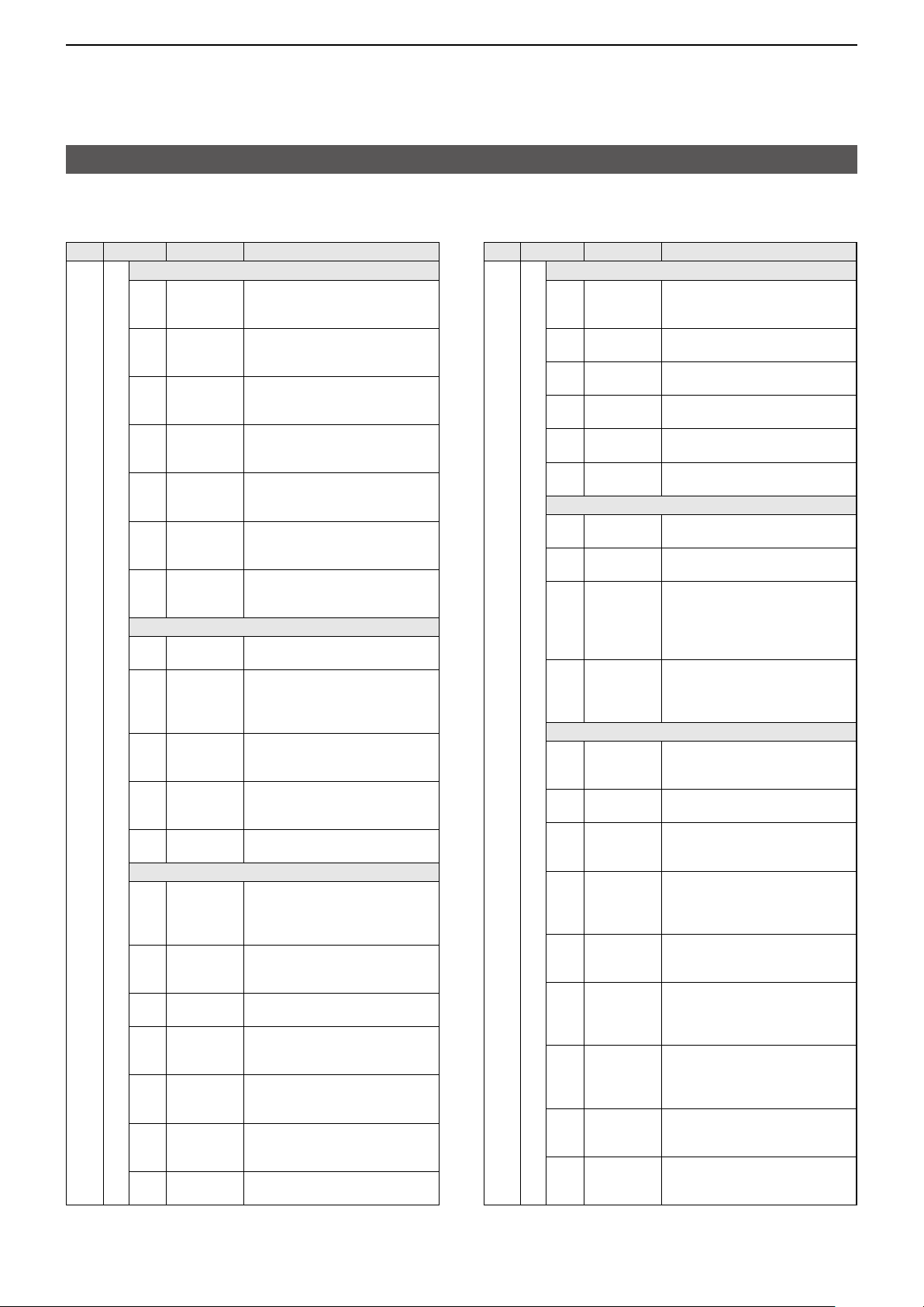
D Command table
Cmd�
Sub cmd� Data Description
1
19*
00 Read the transceiver ID
1A* 00 See pp� 17
01 See p� 18�
02*
03 See p� 19� Send/read the selected IF filter width
04 See p� 19� Send/read the selected AGC time
05 SET > Tone Control/TBW
and 18�
5
See p� 19� Send/read memory keyer contents
0001 See p� 19� RX > SSB >
0002 00 ~ 10 RX > SSB >
0003 00 ~ 10 RX > SSB >
0004 See p� 19� RX > AM >
0005 00 ~ 10 RX > AM >
0006 00 ~ 10 RX > AM >
0007 See p� 19� RX > FM >
0008 00 ~ 10 RX > FM >
0009 00 ~ 10 RX > FM >
0010 See p� 19� RX > DV >
0011 00 ~ 10 RX > DV >
0012 00 ~ 10 RX > DV >
0013 00 ~ 10 RX > WFM >
0014 00 ~ 10 RX > WFM >
0015 See p� 19� RX > CW >
0016 See p� 19� RX > RTTY >
0017 00 ~ 10 TX > SSB >
0018 00 ~ 10 TX > SSB >
0019 See p� 19� TX > SSB >
Send/read memory contents
Send/read band stacking register contents
constant
Send/read RX HPF/LPF settings
Send/read RX Tone (Bass) level
(00=–5 ~ 10=+5)
Send/read RX Tone (Treble) level
(00=–5 ~ 10=+5)
Send/read RX HPF/LPF settings
Send/read RX Tone (Bass) level
(00=–5 ~ 10=+5)
Send/read RX Tone (Treble) level
(00=–5 ~ 10=+5)
Send/read RX HPF/LPF settings
Send/read RX Tone (Bass) level
(00=–5 ~ 10=+5)
Send/read RX Tone (Treble) level
(00=–5 ~ 10=+5)
Send/read RX HPF/LPF settings
Send/read RX Tone (Bass) level
(00=–5 ~ 10=+5)
Send/read RX Tone (Treble) level
(00=–5 ~ 10=+5)
Send/read RX Tone (Bass) level
(00=–5 ~ 10=+5)
Send/read RX Tone (Treble) level
(00=–5 ~ 10=+5)
Send/read RX HPF/LPF settings
Send/read RX HPF/LPF settings
Send/read TX Tone (Bass) level
(00=–5 ~ 10=+5)
Send/read TX Tone (Treble) level
(00=–5 ~ 10=+5)
Send/read TX bandwidth for wide
Cmd�
Sub cmd� Data Description
1A* 05 SET > Tone Control/TBW
0020 See p� 19� TX > SSB >
0021 See p� 19� TX > SSB >
0022 See p� 19� TX > SSB-D >
0023 00 ~ 10 TX > AM >
0024 00 ~ 10 TX > AM >
0025 00 ~ 10 TX > FM >
0026 00 ~ 10 TX > FM >
0027 00 ~ 10 TX > DV >
0028 00 ~ 10 TX > DV >
SET > Function
0029 0000 ~ 0255
0030 00/01 Send/read the Beep Level Limit
0031 00/01 Send/read the Beep (Confirmation)
0032 00/01 Send/read the Home CH Beep
0033 00 ~ 03 Send/read the Band Edge Beep
0034 00 ~ 04 Send/read the Auto Power OFF
0035 00 ~ 03 Send/read the Power Save setting
0036 00 ~ 03 Send/read the Max TX Power
0037 00 ~ 04 Send/read the Max TX Power (DC
0038 00 ~ 05 Send/read the TX Delay (HF) setting
Send/read TX bandwidth for mid
Send/read TX bandwidth for narrow
Send/read TX bandwidth
Send/read TX Tone (Bass) level
(00=–5 ~ 10=+5)
Send/read TX Tone (Treble) level
(00=–5 ~ 10=+5)
Send/read TX Tone (Bass) level
(00=–5 ~ 10=+5)
Send/read TX Tone (Treble) level
(00=–5 ~ 10=+5)
Send/read TX Tone (Bass) level
(00=–5 ~ 10=+5)
Send/read TX Tone (Treble) level
(00=–5 ~ 10=+5)
Send/read the Beep Level setting
(0000=Minimum ~ 0255=Maximum)
setting
(00=OFF, 01=ON)
setting
(00=OFF, 01=ON)
setting
(00=OFF, 01=ON)
setting
( 00=OFF, 01=ON (Default),
02=ON (User),
03=ON (User) & TX Limit)
setting
( 00=OFF, 01=30 min, 02=60 min,
03=90 min, 04=120 min)
( 00=OFF, 01=Auto (Short),
02=Auto (Middle), 03=Auto (Long))
(Battery Pack) setting
( 00=0�5 W, 01=1 W, 02=2�5 W,
03=5 W)
13�8V) setting
( 00=0�5 W, 01=1 W, 02=2�5 W,
03=5 W, 04=10 W)
( 00=OFF, 01=10 ms, 02=15 ms,
03=20 ms, 04=25 ms, 05=30 ms)
5
Page 7
REMOTE CONTROL
Remote control (CI-V) information
D Command table
Cmd�
Sub cmd� Data Description
1A* 05 SET > Function
0039 00 ~ 05 Send/read the TX Delay (50 MHz)
0041 00 ~ 05 Send/read the TX Delay (144 MHz)
0042 00 ~ 05 Send/read the TX Delay (430 MHz)
0043 00 ~ 05 Send/read the Time-Out Timer
0044 00/01 Send/read the PTT Lock setting
0045 00/01 SPLIT >
0046 See p� 19� SPLIT >
0047 00/01 SPLIT >
0048 00/01
0049 00 ~ 02 Send/read the Auto Repeater setting
0050 00 ~ 02 Send/read the RTTY Mark
0051 00 ~ 02 Send/read the RTTY Shift Width
0052 00/01 Send/read the RTTY Keying Polarity
0053 00/01
0054 00/01
0055 00/01
0056 00 ~ 02 SPEECH >
setting
( 00=OFF, 01=10 ms, 02=15 ms,
03=20 ms, 04=25 ms, 05=30 ms)
setting
( 00=OFF, 01=10 ms, 02=15 ms,
03=20 ms, 04=25 ms, 05=30 ms)
setting
( 00=OFF, 01=10 ms, 02=15 ms,
03=20 ms, 04=25 ms, 05=30 ms)
setting
( 00=OFF, 01=3 min, 02=5 min,
03=10 min, 04=20 min, 05=30 min)
( 00=OFF, 01=ON)
Send/read the Quick SPLIT setting
( 00=OFF, 01=ON)
Send/read the SPLIT Offset setting
Send/read the SPLIT LOCK setting
( 00=OFF, 01=ON)
Send/read the Tuner (PTT Start) setting
( 00=OFF, 01=ON)
( 00=OFF, 01=ON (DUP),
02=ON (DUP,TONE))
Frequency setting
( 00=1275 Hz, 01=1615 Hz,
02=2125 Hz)
setting
( 00=170 Hz, 01=200 Hz, 02=425 Hz)
setting
( 00=Normal, 01=Reverse)
SPEECH >
Send/read the SPEECH Language
setting
( 00=Japanese, 01=English)
SPEECH >
Send/read the Alphabet setting
( 00=Normal, 01=Phonetic Code)
SPEECH >
Send/read the SPEECH Speed setting
( 00=Slow, 01=Fast)
Send/read the RX Call Sign
SPEECH setting
( 00=OFF, 01=ON (Kerchunk),
02=ON (All))
Cmd�
Sub cmd� Data Description
1A* 05 SET > Function
0057 00/01 SPEECH >
0058 00/01 SPEECH >
0059 00/01 SPEECH >
0060 00/01
0061 0000 ~ 0255
0062 00/01 Send/read the [SPEECH/LOCK]
0063 00/01 Send/read the Lock Function setting
0064 00/01 Send/read the Memo Pad Quantity
0065 00 ~ 02 Send/read the MAIN DIAL Auto TS
0066 00/01 Send/read the MIC Up/Down Speed
0067 00 ~ 02 Send/read the
0068 00 ~ 02 Send/read the [NOTCH] Switch
0069 00/01 Send/read the
0070 00/01
0071 00/01 Send/read the Charging (Power ON)
0072 00/01 Send/read the
0073 00/01 Send/read the Power OFF Setting
SET > Function >
0074 See p� 20�
0075 See p� 20�
0076 See p� 20�
0077 See p� 20�
Send/read the RX>CS SPEECH setting
( 00=OFF, 01=ON)
Send/read the MIC Up/Down
SPEECH setting
( 00=OFF, 01=ON)
Send/read the S-Level SPEECH setting
( 00=OFF, 01=ON)
SPEECH >
Send/read the MODE SPEECH setting
( 00=OFF, 01=ON)
SPEECH >
Send/read the SPEECH Level setting
(
0000=0% ~ 0255=100%)
Switch setting
( 00=SPEECH/LOCK,
01=LOCK/SPEECH)
( 00=MAIN DIAL, 01=PANEL)
setting
( 00=5 ch, 01=10 ch)
setting
(00=OFF, 01=Low, 02=High)
setting
(00=Slow, 01=Fast)
(SSB) setting
(00=Auto, 01=Manual, 02=Auto/Manual)
(AM) setting
(00=Auto, 01=Manual, 02=Auto/Manual)
Synchronous Tuning setting
(00=OFF, 01=ON)
Send/read the CW Normal Side setting
(00=LSB, 01=USB)
setting
(00=OFF, 01=ON)
(Phone, Tablet, PC) setting
(00=OFF, 01=ON)
(for Remote Control) setting
( 00=Shutdown only,
01=Standby/Shutdown)
Remote MIC Key
Send/read the [A] setting
Send/read the [B] setting
Send/read the [] setting
Send/read the [] setting
[NOTCH] Switch
SSB/CW
USB Power Input
6
Page 8
REMOTE CONTROL
Remote control (CI-V) information
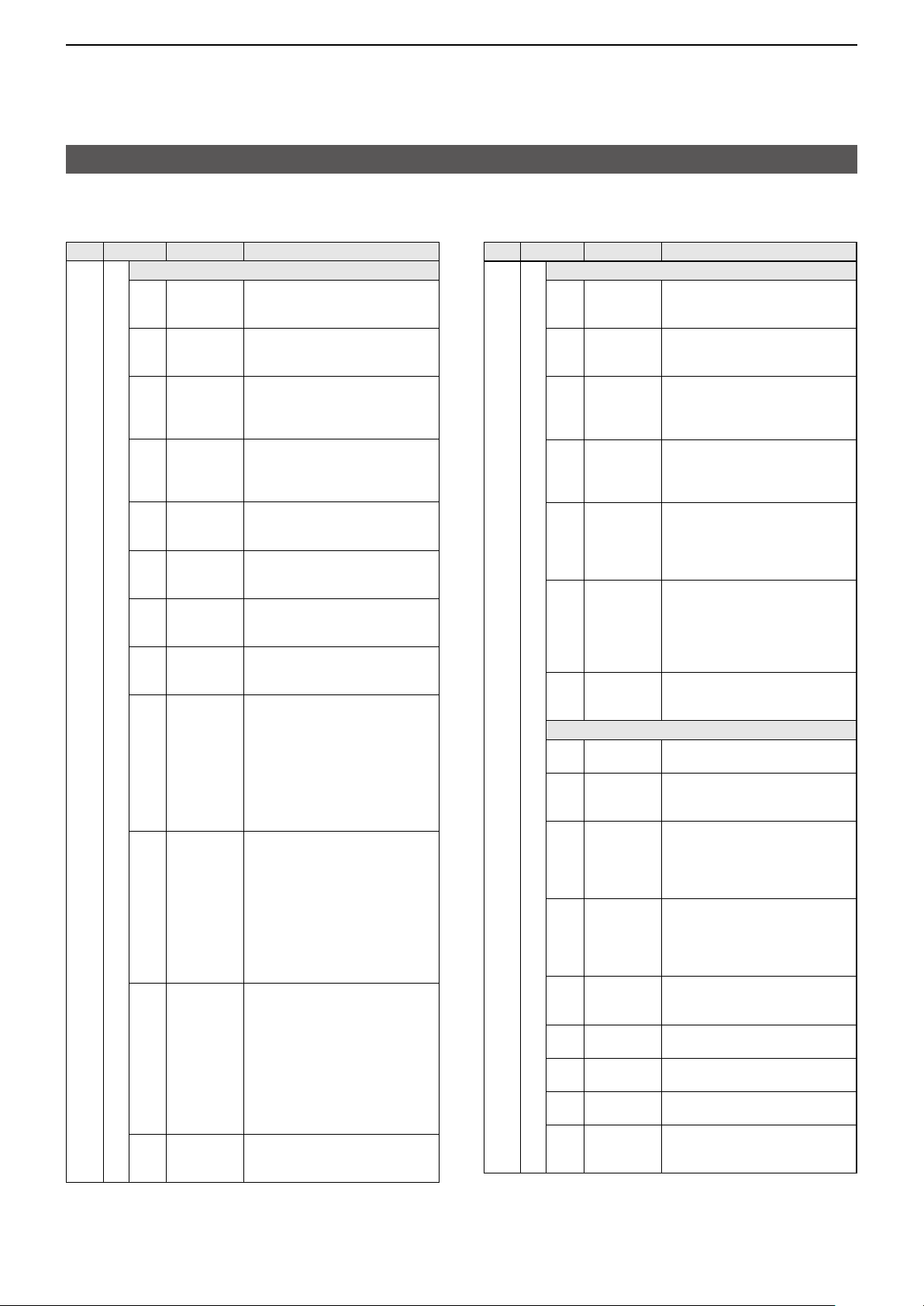
D Command table
Cmd�
Sub cmd� Data Description
1A* 05 SET > Function >
0078 00/01
0079 00/01
0080 00/01
0081 00/01
0082 00/01
0083 00/01
0084 00/01
SET > Function
0085 00/01
0086 00 ~ 02 Send/read the Full Keyboard Layout
0087 00/01 Send/read the Screen Capture
0088 00/01 Send/read the Screen Capture File
0089 0000 ~ 0255 Send/read the REF Adjust setting
SET > DV Set
0090 00 ~ 03 Send/read the Standby Beep setting
0091 00 ~ 03 Send/read the Auto Reply setting
0092 00/01 Send/read the DV Data TX setting
0093 00/01 DV Fast Data >
0094 00/01 DV Fast Data >
0095 00 ~ 10
0096 00 ~ 02 Send/read the Digital Monitor setting
Remote MIC Key
Send/read the
setting
(00=OFF, 01=ON)
Send/read the
setting
(00=OFF, 01=ON)
Send/read the
setting
(00=OFF, 01=ON)
Send/read the
setting
(00=OFF, 01=ON)
Send/read the
setting
(00=OFF, 01=ON)
Send/read the
setting
(00=OFF, 01=ON)
Send/read the
setting
(00=OFF, 01=ON)
Send/read the Keyboard Type setting
(00=Ten-key, 01=Full Keyboard)
setting
( 00=English, 01=German,
02=French)
[POWER] Switch setting
(00=OFF, 01=ON)
Type setting
(00=PNG, 01=BMP)
0000=0% ~ 0255=100%)
(
( 00=OFF, 01=ON,
02=ON (to me:High Tone),
03=ON (to me:Alarm/High Tone))
( 00=OFF, 01=ON, 02=Voice,
03=Position)
(00=PTT, 01=Auto)
Send/read the Fast Data setting
(00=OFF, 01=ON)
Send/read the GPS Data Speed setting
(00=Slow, 01=Fast)
DV Fast Data >
Send/read the TX Delay (PTT) setting
(00=OFF, 01=1sec ~ 10=10sec)
(00=Auto, 01=Digital, 02=Analog)
Mode Select (SSB)
Mode Select (CW)
Mode Select (RTTY)
Mode Select (AM)
Mode Select (FM)
Mode Select (DV)
Mode Select (WFM)
Cmd�
Sub cmd� Data Description
1A* 05 SET > DV Set
0097 00/01 Send/read the Digital Repeater Set
0098 00/01
0099 00/01
0100 00/01 Send/read the BK setting
0101 00/01 Send/read the EMR setting
0102 0000 ~ 0255 Send/read the EMR AF Level setting
SET > QSO/RX Log
0103 00/01 Send/read the QSO Log setting
0104 00/01
0105 00 ~ 02
0106 00 ~ 02 CSV Format >
SET > Connectors
0107 00 ~ 02
0108 00 ~ 30 Send/read the Phones Level setting
0109 00/01 USB AF/IF Output
0110 0000 ~ 0255 USB AF/IF Output
0111 00/01 USB AF/IF Output >
0112 00/01 USB AF/IF Output
0113 0000 ~ 0255 USB AF/IF Output
0114 00/01 WLAN AF/IF Output >
0115 00/01
setting
(00=OFF, 01=ON)
Send/read the DV Auto Detect setting
(00=OFF, 01=ON)
Send/read the RX Record (RPT) setting
(00=ALL, 01=Latest Only)
(00=OFF, 01=ON)
(00=OFF, 01=ON)
(0000=0% ~ 0255=100%)
(00=OFF, 01=ON)
Send/read the RX History Log setting
(00=OFF, 01=ON)
CSV Format >
Send/read the Separator/Decimal setting
( 00=Separator is “ , ” and Decimal is “ � ,”
01=Separator is “ ; ” and Decimal is “ � ,”
02=Separator is “ ; ” and Decimal is “ , ”)
Send/read the Date setting
( 00=“yyyy/mm/dd,” 01=“mm/dd/yyyy,”
02=“dd/mm/yyyy”)
Send/read the SP Jack Function setting
( 00=Speaker, 01=Phone,
02=Phone (L+R))
(00=–15 ~ 30=+15)
Send/read the Output Select setting
(00=AF, 01=IF)
Send/read the AF Output Level
setting
0000=0% ~ 0255=100%)
(
Send/read the AF SQL setting
(00=OFF (Open), 01=ON)
Send/read the AF Beep/Speech���
Output setting
(00=OFF, 01=ON)
Send/read the IF Output Level
setting
0000=0% ~ 0255=100%)
(
Send/read the Output Select setting
(00=AF, 01=IF)
WLAN AF/IF Output >
Send/read the AF SQL setting
(00=OFF (Open), 01=ON)
>
>
>
>
7
Page 9
REMOTE CONTROL
Remote control (CI-V) information
D Command table
Cmd�
Sub cmd� Data Description
1A* 05 SET > Connectors
0116 0000 ~ 0255
0117 0000 ~ 0255
0118 00 ~ 03
0119 00 ~ 03 MOD Input >
0120 00/01 SEND Output >
0121 00/01 SEND Output >
0123 00/01 SEND Output >
0124 00/01 SEND Output >
0125 00 ~ 04 USB SEND/Keying >
0126 00 ~ 04 USB SEND/Keying >
0127 00 ~ 04 USB SEND/Keying >
0128 00/01 External Keypad >
MOD Input >
Send/read the USB MOD Level setting
(
0000=0% ~ 0255=100%)
MOD Input >
Send/read the WLAN MOD Level setting
(
0000=0% ~ 0255=100%)
MOD Input >
Send/read the DATA OFF MOD setting
( 00=MIC, 01=USB,
02=MIC, USB, 03=WLAN)
Send/read the DATA MOD setting
( 00=MIC, 01=USB,
02=MIC, USB, 03=WLAN)
Send/read the HF setting
(00=OFF, 01=ON)
Send/read the 50M setting
(00=OFF, 01=ON)
Send/read the 144M setting
(00=OFF, 01=ON)
Send/read the 430M setting
(00=OFF, 01=ON)
Send/read the USB SEND setting
( 00=OFF, 01=USB (A) DTR,
02=USB (A) RTS, 03=USB (B) DTR,
04=USB (B) RTS)
L You cannot select the terminal
which is already selected in the
“USB Keying (CW)” or “USB
Keying (RTTY)” item�
Send/read the USB Keying (CW)
setting
( 00=OFF, 01=USB (A) DTR,
02=USB (A) RTS, 03=USB (B) DTR,
04=USB (B) RTS)
L You cannot select the terminal
which is already selected in the
“USB SEND” or “USB Keying
(RTTY)” item�
Send/read the USB Keying (RTTY)
setting
( 00=OFF, 01=USB (A) DTR,
02=USB (A) RTS, 03=USB (B) DTR,
04=USB (B) RTS)
L You cannot select the terminal
which is already selected in the
“USB SEND” or “USB Keying
(CW)” item�
Send/read the VOICE setting
(00=OFF, 01=ON)
Cmd�
Sub cmd� Data Description
1A* 05 SET > Connectors
0129 00/01 External Keypad >
0130 00/01 External Keypad >
0131 00/01 CI-V >
0132 00/01 CI-V >
0133 00 ~ 03 USB (B) Function >
0134 00/01 USB (B) Function >
0135 00/01 Send/read the MIC Jack 8V Output
SET > Display
0136 0000 ~ 0255 Send/read the LCD Backlight setting
0137 00/01 Send/read the LCD Backlight Auto
0138 00 ~ 06 Send/read the Screen Saver
0139 00 ~ 06 Send/read the Screen Saver (DC
0140 00/01
0141 00/01 Send/read the RX LED setting
0142 00/01
0143 00/01
0144 00/01 Send/read the Group Name Popup
Send/read the KEYER setting
(00=OFF, 01=ON)
Send/read the RTTY setting
(00=OFF, 01=ON)
Send/read the CI-V Transceive
setting
(00=OFF, 01=ON)
Send/read the CI-V USB Echo Back
setting
(00=OFF, 01=ON)
Send/read the USB (B) Function
setting
( 00=OFF, 01=RTTY Decode,
02=DV Data, 03=Weather)
Send/read the GPS Out setting
(00=OFF, 01=ON)
L It is valid when “USB (B)
Function” is set to “OFF” or “DV
Data�”
setting
(00=OFF, 01=ON)
(0000=0% ~ 0255=100%)
Adjust setting
(00=OFF, 01=ON)
(Battery Pack) setting
( 00=OFF, 01=1min, 02=2min,
03=5min, 04=15min, 05=30min,
06=60min)
13�8 V) setting
( 00=OFF, 01=1min, 02=2min,
03=5min, 04=15min, 05=30min,
06=60min)
Send/read the Screen OFF
[POWER] Switch setting
(00=OFF, 01=ON)
(00=OFF, 01=ON)
Send/read the Meter Peak Hold setting
(00=OFF, 01=ON)
Send/read the Memory Name setting
(00=OFF, 01=ON)
setting
(00=OFF, 01=ON)
8
Page 10

REMOTE CONTROL
Remote control (CI-V) information
D Command table
Cmd�
Sub cmd� Data Description
1A* 05 SET > Display
0145 00 ~ 03 Send/read the RX Call Sign Display
0146 00/01 Send/read the RX Position Indicator
0147 00/01 Send/read the RX Position Display
0148 00 ~ 04 Send/read the RX Position Display
0149 00/01 Send/read the Reply Position
0150 00/01 Send/read the RX Picture Indicator
0151 00/01
0152 00 ~ 02 Send/read the TX Call Sign Display
0153 00/01 Send/read the Scroll Speed setting
0154 00/01
0155 00/01
0156 00/01 Display Unit >
0157 00/01 Display Unit >
0158 00 ~ 02 Display Unit >
0159 00/01 Display Unit >
0160 00 ~ 03 Display Unit >
0161 00/01 Display Unit >
0162 00 ~ 03 Display Unit >
0163 00/01
0164 00/01
setting
( 00=OFF, 01=Normal,
02=RX Hold, 03=Hold)
setting
(00=OFF, 01=ON)
setting
(00=OFF, 01=ON)
Timer setting
( 00=5sec, 01=10sec, 02=15sec,
03=30sec, 04=Hold)
Display setting
(00=OFF, 01=ON)
setting
(00=OFF, 01=ON)
Send/read the DV RX Backlight setting
(00=OFF, 01=ON)
setting
( 00=OFF, 01=Your Call Sign,
02=My Call Sign)
(00=Slow, 01=Fast)
Send/read the Opening Message setting
(00=OFF, 01=ON)
Send/read the Power ON Check setting
(00=OFF, 01=ON)
Send/read the Latitude/Longitude
setting
Send/read the Altitude/Distance setting
(00=m, 01=ft/mi)
Send/read the Speed setting
(00=km/h, 01=mph, 02=knots)
Send/read the Temperature setting
(00=°C, 01=°F)
Send/read the Barometric setting
(00=hPa, 01=mb, 02=mmHg, 03=inHg)
Send/read the Rainfall setting
(00=mm, 01=inch)
Send/read the Wind Speed setting
(00=m/s, 01=km/h, 02=mph, 03=knots)
Send/read the Display Language setting
(00=English, 01=Japanese)
Send/read the System Language setting
(00=English, 01=Japanese)
Cmd�
Sub cmd� Data Description
1A* 05 SET > Time Set
0165 20000101 ~
20991231
0166 0000 ~ 2359 Date/Time >
0167 00/01 Date/Time >
0168 See p� 18� Date/Time >
0169 00/01
0170 See p� 20� Send/read the UTC Offset setting
SET > SD Card
0171 00 ~ 02 Import/Export > CSV Format >
0172 00 ~ 02 Import/Export > CSV Format >
SCOPE > SCOPE SET
0173 00/01 Send/read the Scope during Tx
0174 00 ~ 02 Send/read the Max Hold setting
0175 00 ~ 02 Send/read the CENTER Type
0176 00/01 Send/read the Marker Position (FIX
0177 00/01 Send/read the VBW setting
0178 00 ~ 03 Send/read the Averaging setting
0179 00/01
0180 See p� 20� Send/read the Waveform Color
0181 See p� 20� Send/read the Waveform Color
0182 See p� 20� Send/read the Waveform Color
0183 00/01
Date/Time >
Send/read the Date setting
( 20000101=2000/1/1 ~
20991231=2099/12/31)
Send/read the Time setting
(0000=00:00 ~ 2359=23:59)
Send/read the NTP Function setting
(00=OFF, 01=ON)
Send/read the NTP Server Address
setting
(Up to 64 characters)
Date/Time >
Send/read the GPS Time Correct
setting
(00=OFF, 01=Auto)
Send/read the Separator/Decimal
setting
( 00=Separator is “ , ” and Decimal is “ � ,”
01=Separator is “ ; ” and Decimal is “ � ,”
02=Separator is “ ; ” and Decimal is “ , ”)
Send/read the Date setting
( 00=“yyyy/mm/dd,” 01=“mm/dd/yyyy,”
02=“dd/mm/yyyy”)
(CENTER Type) setting
(00=OFF, 01=ON)
( 00=OFF, 01=10s Hold, 02=ON)
Display setting
( 00=Filter Center,
Carrier Point Center,
01=
Carrier Point Center (Abs� Freq�))
02=
Type) setting
(00=Filter Center, 01=Carrier Point)
(00=Narrow, 01=Wide)
(00=OFF, 01=2, 02=3, 03=4)
Send/read the Waveform Type setting
(00=Fill, 01=Fill+Line)
(Current) setting
(Line) setting
(Max Hold) setting
Send/read the Waterfall Display setting
(00=OFF, 01=ON)
9
Page 11

REMOTE CONTROL
Remote control (CI-V) information
D Command table
Cmd�
Sub cmd� Data Description
1A* 05 SCOPE > SCOPE SET
0184 00 ~ 02
0185 00 ~ 02 Send/read the Waterfall Size
0186 00 ~ 07 Send/read the Waterfall Peak Color
0187 00/01 Send/read the Waterfall Marker
0188 See p� 20� FIX Edges > 0�03 - 1�60 >
0189 See p� 20� FIX Edges > 0�03 - 1�60 >
0190 See p� 20� FIX Edges > 0�03 - 1�60 >
0191 See p� 20� FIX Edges > 1�60 - 2�00 >
0192 See p� 20� FIX Edges > 1�60 - 2�00 >
0193 See p� 20� FIX Edges > 1�60 - 2�00 >
0194 See p� 20� FIX Edges > 2�00 - 6�00 >
0195 See p� 20� FIX Edges > 2�00 - 6�00 >
0196 See p� 20� FIX Edges > 2�00 - 6�00 >
0197 See p� 20� FIX Edges > 6�00 - 8�00 >
0198 See p� 20� FIX Edges > 6�00 - 8�00 >
0199 See p� 20� FIX Edges > 6�00 - 8�00 >
0200 See p� 20� FIX Edges > 8�00 - 11�00 >
0201 See p� 20� FIX Edges > 8�00 - 11�00 >
0202 See p� 20� FIX Edges > 8�00 - 11�00 >
0203 See p� 20� FIX Edges > 11�00 - 15�00 >
0204 See p� 20� FIX Edges > 11�00 - 15�00 >
0205 See p� 20� FIX Edges > 11�00 - 15�00 >
0206 See p� 20� FIX Edges > 15�00 - 20�00 >
0207 See p� 20� FIX Edges > 15�00 - 20�00 >
0208 See p� 20� FIX Edges > 15�00 - 20�00 >
0209 See p� 20� FIX Edges > 20�00 - 22�00 >
0210 See p� 20� FIX Edges > 20�00 - 22�00 >
Send/read the Waterfall Speed setting
(00=Slow, 01=Mid, 02=Fast)
(Expand Screen) setting
(00=Small, 01=Mid, 02=Large)
Level setting
(00=Grid1 ~ 07=Grid8)
Auto-hide setting
(00=OFF, 01=ON)
Send/read the No�1 setting
Send/read the No�2 setting
Send/read the No�3 setting
Send/read the No�1 setting
Send/read the No�2 setting
Send/read the No�3 setting
Send/read the No�1 setting
Send/read the No�2 setting
Send/read the No�3 setting
Send/read the No�1 setting
Send/read the No�2 setting
Send/read the No�3 setting
Send/read the No�1 setting
Send/read the No�2 setting
Send/read the No�3 setting
Send/read the No�1 setting
Send/read the No�2 setting
Send/read the No�3 setting
Send/read the No�1 setting
Send/read the No�2 setting
Send/read the No�3 setting
Send/read the No�1 setting
Send/read the No�2 setting
Cmd�
Sub cmd� Data Description
1A* 05 SCOPE > SCOPE SET
0211 See p� 20� FIX Edges > 20�00 - 22�00 >
0212 See p� 20� FIX Edges > 22�00 - 26�00 >
0213 See p� 20� FIX Edges > 22�00 - 26�00 >
0214 See p� 20� FIX Edges > 22�00 - 26�00 >
0215 See p� 20� FIX Edges > 26�00 - 30�00 >
0216 See p� 20� FIX Edges > 26�00 - 30�00 >
0217 See p� 20� FIX Edges > 26�00 - 30�00 >
0218 See p� 20� FIX Edges > 30�00 - 45�00 >
0219 See p� 20� FIX Edges > 30�00 - 45�00 >
0220 See p� 20� FIX Edges > 30�00 - 45�00 >
0221 See p� 20� FIX Edges > 45�00 - 60�00 >
0222 See p� 20� FIX Edges > 45�00 - 60�00 >
0223 See p� 20� FIX Edges > 45�00 - 60�00 >
0224 See p� 20� FIX Edges > 60�00 - 74�80 >
0225 See p� 20� FIX Edges > 60�00 - 74�80 >
0226 See p� 20� FIX Edges > 60�00 - 74�80 >
0227 See p� 20� FIX Edges > 74�80 - 108�00 >
0228 See p� 20� FIX Edges > 74�80 - 108�00 >
0229 See p� 20� FIX Edges > 74�80 - 108�00 >
0230 See p� 20� FIX Edges > 108�00 - 137�00 >
0231 See p� 20� FIX Edges > 108�00 - 137�00 >
0232 See p� 20� FIX Edges > 108�00 - 137�00 >
0233 See p� 20� FIX Edges > 137�00 - 200�00 >
0234 See p� 20� FIX Edges > 137�00 - 200�00 >
0235 See p� 20� FIX Edges > 137�00 - 200�00 >
0236 See p� 20� FIX Edges > 400�00 - 470�00 >
0237 See p� 20� FIX Edges > 400�00 - 470�00 >
0238 See p� 20� FIX Edges > 400�00 - 470�00 >
Send/read the No�3 setting
Send/read the No�1 setting
Send/read the No�2 setting
Send/read the No�3 setting
Send/read the No�1 setting
Send/read the No�2 setting
Send/read the No�3 setting
Send/read the No�1 setting
Send/read the No�2 setting
Send/read the No�3 setting
Send/read the No�1 setting
Send/read the No�2 setting
Send/read the No�3 setting
Send/read the No�1 setting
Send/read the No�2 setting
Send/read the No�3 setting
Send/read the No�1 setting
Send/read the No�2 setting
Send/read the No�3 setting
Send/read the No�1 setting
Send/read the No�2 setting
Send/read the No�3 setting
Send/read the No�1 setting
Send/read the No�2 setting
Send/read the No�3 setting
Send/read the No�1 setting
Send/read the No�2 setting
Send/read the No�3 setting
10
Page 12

REMOTE CONTROL
Remote control (CI-V) information
D Command table
Cmd�
Sub cmd� Data Description
1A* 05 AUDIO > AUDIO SCOPE SET
0239 00/01 Send/read the FFT Scope
0240 See p� 20� Send/read the FFT Scope
0241 00/01 Send/read the FFT Scope Waterfall
0242 See p� 20�
VOICE
0243 0000 ~ 0255 Send/read the TX LEVEL setting
0244 00/01
0245 01 ~ 15
KEYER > KEYER 001
0246 00 ~ 04 Send/read the Number Style setting
0247 01 ~ 08
0248 0001 ~ 9999 Send/read Present Number setting
KEYER > CW-KEY SET
0249 0000 ~ 0255 Send/read Side Tone Level setting
0250 00/01
0251 01 ~ 60
0252 28 ~ 45 Send/read Dot/Dash Ratio setting
0253 00 ~ 03 Send/read Rise Time setting
0254 00/01 Send/read Paddle Polarity setting
0255 00 ~ 02 Send/read Key Type setting
0256 00 ~ 02
DECODE > RTTY DECODE SET
0257 00 ~ 03 Send/read the FFT Scope Averaging
0258 See p� 20� Send/read the FFT Scope
0259 00/01
Waveform Type setting
(00=Line, 01=Fill)
Waveform Color setting
Display setting
(00=OFF, 01=ON)
Send/read the Oscilloscope
Waveform Color setting
0000=0% ~ 0255=100%)
(
VOICE TX SET >
Send/read the Auto Monitor setting
(00=OFF, 01=ON)
VOICE TX SET >
Send/read the Repeat Time setting
(01=1sec ~ 15=15sec)
Send/read the Count Up Trigger setting
(01=M1 ~ 08=M8)
(0001=1 ~ 9999=9999)
0000=0% ~ 0255=100%)
(
Send/read Side Tone Level Limit setting
(00=OFF, 01=ON)
Send/read Keyer Repeat Time setting
(01=1sec ~ 60=60sec)
( 28=1:1:2�8 ~ 45=1:1:4�5
in 0�1 steps)
( 00=2ms, 01=4ms,
02=6ms, 03=8ms)
(00=Normal, 01=Reverse)
(00=Straight, 01=Bug, 02=Paddle)
Send/read MIC Up/Down Keyer setting
( 00=OFF, 01=ON (UP/DOWN),
02=ON (A/B))
setting
(00=OFF, 01=2, 02=3, 03=4)
Waveform Color setting
Send/read the Decode USOS setting
(00=OFF, 01=ON)
Cmd�
Sub cmd� Data Description
1A* 05 DECODE > RTTY DECODE SET
0260 00/01 Send/read the Decode New Line
0261 00/01 Send/read the TX USOS setting
0262 See p� 20� Send/read the Font Color (Receive)
0263 See p� 20� Send/read the Font Color (Transmit)
DECODE > RTTY DECODE LOG
0264 00/01 Send/read the Decode Log setting
0265 00/01 Log Set >
0266 00/01 Log Set >
0267 00/01
0268 00/01 Log Set >
RECORD > Recorder Set
0269 00/01 Send/read the TX REC Audio setting
0270 00/01 Send/read the RX REC Condition
0271 00/01 Send/read the File Split setting
0272 00/01
0273 00 ~ 03 Send/read the PRE-REC for PTT
RECORD > Player Set
0274 00 ~ 03 Send/read the Skip Time setting
SCAN > SCAN SET
0275 00/01 Send/read the SCAN Speed setting
0276 00/01
0277 00 ~ 10 Send/read the Pause Timer setting
0278 00 ~ 06
0279 00 ~ 04 Send/read the Temporary Skip
Code setting
(00=CR,LF,CR+LF, 01=CR+LF)
(00=OFF, 01=ON)
setting
setting
(00=OFF, 01=ON)
Send/read the File Type setting
(00=Text, 01=HTML)
Send/read the Time Stamp setting
(00=OFF, 01=ON)
Log Set >
Send/read the Time Stamp (Time) setting
(00=Local, 01=UTC)
Send/read the Time Stamp
(Frequency) setting
(00=OFF, 01=ON)
(00=Direct, 01= Monitor)
setting
(00=Always, 01=Squelch Auto)
(00=OFF, 01=ON)
Send/read the PTT Auto REC setting
(00=OFF, 01=ON)
Auto REC setting
( 00=OFF, 01=5sec,
02=10sec, 03=15sec)
( 00=3sec, 01=5sec,
02=10sec, 03=30sec)
(00=Slow, 01=Fast)
Send/read the SCAN Resume setting
(00=OFF, 01=ON)
00=2sec ~ 09=20sec in 2 seconds,
(
10=HOLD)
Send/read the Resume Timer setting
(00=0sec ~ 05=5sec, 06=HOLD)
Timer setting
( 00=5min, 01=10min, 02=15min,
03=While Scanning,
04=While Powered ON)
11
Page 13

REMOTE CONTROL
Remote control (CI-V) information
D Command table
Cmd�
Sub cmd� Data Description
1A* 05 SCAN > SCAN SET
0280 00/01 Send/read the MAIN DIAL Operation
GPS
0281 00 ~ 02 GPS Set >
0282 00/01
0283 00/01 GPS Set > GPS Option >
0284 00 ~ 05 GPS Set > GPS Option >
0285 00/01 GPS Set > GPS Option >
0286 See p� 21� GPS Set >
0287 00 ~ 02 Send/read the GPS TX Mode setting
GPS > GPS TX Mode > D-PRS
0288 See p� 18�
0289 00 ~ 03 Send/read the TX Format setting
GPS > GPS TX Mode > D-PRS > TX Format > Position
0290 00 ~ 03 Send/read the Symbol setting
0291 See pp� 18
and 21�
0292 See pp� 18
and 21�
0293 See pp� 18
and 21�
0294 See pp� 18
and 21�
0295 00 ~ 42 Send/read the SSID setting
0296 00 ~ 03 Send/read the Comment setting
0297 See p� 18�
0298 See p� 18�
0299 See p� 18�
0300 See p� 18�
(SCAN) setting
(00=OFF, 01=Up/Down)
Send/read the GPS Select setting
(00=OFF, 01=ON, 02=Manual)
GPS Set > GPS Option >
Send/read the SBAS setting
(00=OFF, 01=ON)
Send/read the GLONASS setting
(00=OFF, 01=ON)
Send/read the Power Save setting
( 00=OFF, 01=1min, 02=2min,
03=4min, 04=8min, 05=Auto)
Send/read the Satellite Information
Out setting
GPS/QZSS/GLONASS,
( 00=
01=GPS Only)
Send/read the Manual Position setting
(00=OFF, 01=D-PRS, 02=NMEA)
Send/read the Unproto Address setting
(Up to 56 characters)
( 00=Position, 01=Object,
02=Item, 03=Weather)
( 00=No�1, 01=No�2,
02=No�3, 03=No�4)
Send/read the Symbol No�1 setting
(2 characters)
Send/read the Symbol No�2 setting
(2 characters)
Send/read the Symbol No�3 setting
(2 characters)
Send/read the Symbol No�4 setting
(2 characters)
( 00= - - -, 01=(- 0),
02= -1 ~ 16= -15,
17= -A ~ 42=-Z)
(00=No�1, 01=No�2, 02=No�3, 03=No�4)
Send/read the Comment No�1 setting
(Up to 43 characters)
Send/read the Comment No�2 setting
(Up to 43 characters)
Send/read the Comment No�3 setting
(Up to 43 characters)
Send/read the Comment No�4 setting
(Up to 43 characters)
Cmd�
Sub cmd� Data Description
1A* 05 GPS > GPS TX Mode > D-PRS > TX Format > Position
0301 00 ~ 02 Send/read the Time Stamp setting
0302 00/01 Send/read the Altitude setting
0303 00 ~ 02
0304 00 ~ 09 Send/read the Power setting
0305 00 ~ 09 Send/read the Height setting
0306 00 ~ 09 Send/read the Gain setting
0307 00 ~ 08 Send/read the Directivity setting
GPS > GPS TX Mode > D-PRS > TX Format > Object
0308 See p� 18� Send/read the Object Name setting
0309 00/01 Send/read the Data Type setting
0310 See pp� 18
and 21�
0311 See p� 18� Send/read the Comment setting
0312 See p� 21� Send/read the Position setting
0313 00 ~ 02
0314 000 ~ 360 Send/read the Course setting
0315 0000 ~ 1850 Send/read the Speed setting
0316 00 ~ 09 Send/read the Power setting
0317 00 ~ 09 Send/read the Height setting
0318 00 ~ 09 Send/read the Gain setting
0319 00 ~ 08 Send/read the Directivity setting
0320 00 ~ 42 Send/read the SSID setting
0321 00/01 Send/read the Time Stamp setting
(00=OFF, 01=DHM, 02=HMS)
(00=OFF, 01=ON)
Send/read the Data Extension setting
( 00=OFF, 01=Course/Speed,
Power/Height/Gain/Directivity)
02=
( 00=0W, 01=1W, 02=4W, 03=9W,
04=16W, 05=25W, 06=36W,
07=49W, 08=64W, 09=81W)
( 00=3m, 01=6m, 02=12m, 03=24m,
04=49m, 05=98m, 06=195m,
07=390m, 08=780m, 09=1561m)
(00=0dB ~ 09=9dB)
( 00=Omni, 01=45ºNE, 02=90ºE,
03=135ºSE, 04=180ºS, 05=
06=270ºW, 07=
(Up to 9 characters)
(00=Live Object, 01=Kill Object)
Send/read the Symbol setting
(2 characters)
(Up to 43 characters)
Send/read the Data Extension setting
( 00=OFF, 01=Course/Speed,
Power/Height/Gain/Directivity)
02=
(000=0º ~ 360=360º)
(0000=0km/h ~ 1850=1850km/h)
( 00=0W, 01=1W, 02=4W, 03=9W,
04=16W, 05=25W, 06=36W,
07=49W, 08=64W, 09=81W)
( 00=3m, 01=6m, 02=12m, 03=24m,
04=49m, 05=98m, 06=195m,
07=390m, 08=780m, 09=1561m)
(00=0dB ~ 09=9dB)
( 00=Omni, 01=45ºNE, 02=90ºE,
03=135ºSE, 04=180ºS, 05=
06=270ºW, 07=
( 00= - - -, 01=(- 0),
02= -1 ~ 16= -15,
17= -A ~ 42= -Z)
(00=DHM, 01=HMS)
315ºNW,
315ºNW,
225ºSW
08=360ºN)
225ºSW
08=360ºN)
,
,
12
Page 14

REMOTE CONTROL
Remote control (CI-V) information
D Command table
Cmd�
Sub cmd� Data Description
1A* 05 GPS > GPS TX Mode > D-PRS > TX Format > Item
0322 See p� 18� Send/read the Item Name setting
0323 00/01 Send/read the Data Type setting
0324 See pp� 18
and 21�
0325 See p� 18� Send/read the Comment setting
0326 See p� 21� Send/read the Position setting
0327 00 ~ 02
0328 000 ~ 360 Send/read the Course setting
0329 0000 ~ 1850 Send/read the Speed setting
0330 00 ~ 09 Send/read the Power setting
0331 00 ~ 09 Send/read the Height setting
0332 00 ~ 09 Send/read the Gain setting
0333 00 ~ 08 Send/read the Directivity setting
0334 00 ~ 42 Send/read the SSID setting
GPS > GPS TX Mode > D-PRS > TX Format > Weather
0335 See pp� 18
and 21�
0336 00 ~ 42 Send/read the SSID setting
0337 See p� 18� Send/read the Comment setting
0338 00 ~ 02 Send/read the Time Stamp setting
GPS > GPS TX Mode > NMEA
0339*600/01 GPS Sentence >
0340*600/01 GPS Sentence >
0341*600/01 GPS Sentence >
(Up to 9 characters)
(00=Live Item, 01=Killed Item)
Send/read the Symbol setting
(2 characters)
(Up to 43 characters)
Send/read the Data Extension setting
( 00=OFF, 01=Course/Speed,
Power/Height/Gain/Directivity)
02=
(000 ~ 360=0º ~ 360º)
( 0000=0km/h ~ 1850=1850km/h)
( 00=0W, 01=1W, 02=4W, 03=9W,
04=16W, 05=25W, 06=36W,
07=49W, 08=64W, 09=81W)
( 00=3m, 01=6m, 02=12m, 03=24m,
04=49m, 05=98m, 06=195m,
07=390m, 08=780m, 09=1561m)
(00=0dB ~ 09=9dB)
( 00=Omni, 01=45ºNE, 02=90ºE,
03=135ºSE, 04=180ºS, 05=
06=270ºW, 07=
( 00= - - -, 01=(- 0),
02= -1 ~ 16= -15,
17= -A ~ 42= -Z)
Send/read the Symbol setting
(2 characters)
( 00= - - -, 01=(- 0),
02= -1 ~ 16= -15,
17= -A ~ 42= -Z)
(Up to 43 characters)
(00=OFF, 01=DHM, 02=HMS)
Send/read the RMC setting
(00=OFF, 01=ON)
Send/read the GGA setting
(00=OFF, 01=ON)
Send/read the GLL setting
(00=OFF, 01=ON)
315ºNW,
08=360ºN)
225ºSW
Cmd�
Sub cmd� Data Description
1A* 05 GPS > GPS TX Mode > NMEA
0342*600/01 GPS Sentence >
0343*600/01 GPS Sentence >
0344*600/01 GPS Sentence >
0345 See p� 18� Send/read the GPS Message setting
GPS > GPS Alarm
0346 See p� 21� Send/read the Alarm Area (Group)
0347 00 ~ 02 Send/read the Alarm Area (RX/
GPS > GPS Logger
0348 00/01 Send/read the GPS Logger setting
0349 00 ~ 06
0350 00/01 Record Sentence >
,
0351 00/01 Record Sentence >
0352 00/01 Record Sentence >
0353 00/01 Record Sentence >
GPS
0354 00 ~ 06 Send/read the GPS Auto TX setting
DTMF > DTMF SET
0355 00 ~ 03 Send/read the DTMF Speed setting
NB
0356 0000 ~ 0255 Send/read the NB LEVEL setting
0357 00 ~ 09 Send/read the NB DEPTH setting
0358 0000 ~ 0255 Send/read the NB WIDTH setting
Send/read the GSA setting
(00=OFF, 01=ON)
Send/read the VTG setting
(00=OFF, 01=ON)
Send/read the GSV setting
(00=OFF, 01=ON)
(Up to 20 characters)
setting
Memory) setting
( 00=Limited, 01=Extended,
02=Both)
(00=OFF, 01=ON)
Send/read the Record Interval setting
( 00=1sec, 01=5sec, 02=10sec,
03=30sec, 04=1min, 05=5min,
06=10min)
Send/read the RMC setting
(00=OFF, 01=ON)
Send/read the GGA setting
(00=OFF, 01=ON)
Send/read the VTG setting
(00=OFF, 01=ON)
Send/read the GSA setting
(00=OFF, 01=ON)
( 00=OFF, 01=30sec, 02=1min,
03=3min, 04=5min, 05=10min,
06=30min)
( 00=100ms, 01=200ms,
02=300ms, 03=500ms)
0000=0% ~ 0255=100%)
(
(00=1 ~ 09=10)
(0000=1 ~ 0255=100)
13
Page 15

REMOTE CONTROL
Remote control (CI-V) information
D Command table
Cmd�
Sub cmd� Data Description
1A* 05 VOX
0359 00 ~ 20 Send/read the VOX DELAY setting
0360 00 ~ 03
CD
0361 00/01 Send/read the Call Sign Display/
GPS Position
0362 00 ~ 02 Send/read the Compass Direction
06 See p� 21� Send/read the DATA mode setting
07 00/01 Send/read the NTP server access
1
08*
09*
00 ~ 02 Read NTP server access result
1
00/01 Read the OVF indicator status
0A 00 ~ 02 Send/read the Share Pictures
1
0B*
00/01 Read the type of power supply
1B* 00 See p� 21�
01 See p� 21� Send/read the TSQL tone frequency
02 See p� 21�
07 See p� 22�
1C 00* 00/01 Send/read the transceiver’s status
01* 00 ~ 02
02* 00/01 Send/read the Transmit frequency
1
03*
1E 00*
01*
02*
See p� 16� Read the transmit frequency
1
1
See p� 16� Read TX band edge frequencies
1
03* See p� 16� Send/read the user-set TX band
( 00=0�0s ~ 20=2�0s in 0�1s steps)
Send/read the VOICE DELAY setting
( 00=OFF, 01=SHORT,
02=MID, 03=LONG)
Name Display setting
( 00=Call Sign Display,
01=Name Display)
setting
( 00=Heading Up, 01=North Up,
02=South Up)
(00=Terminate, 01=Initiate)
(00= Accessing, or have not
accessed after Power ON,
01=Succeeded, 02=Failed)
(00=OFF, 01=ON)
function status
( 00=OFF, 01=ON, 02=ON (Repeat))
L While transmitting the picture
using the DV Fast Data function,
sends ON even if the status is set
to OFF�
based on the current voltage
( 00=External power supply,
01=Battery pack)
Send/read the Repeater tone frequency
Send/read the DTCS code and polarity
Send/read the CSQL code (DV mode)
(00=RX, 01=TX)
Send/read the Antenna tuner's status
(00=OFF, 01=ON, 02=Tune)
monitor (XFC)
(00=OFF, 01=ON)
Read number of available TX
frequency band
Read number of user-set TX
frequency band
edge frequencies
Cmd�
Sub cmd� Data Description
1F* 00 See p� 22� SET > My Station >
Send/read the My Call Sign setting
01 See p� 22� CS >
Send/read the UR, R1, R2 setting
02 See p� 22� SET > My Station >
Send/read the TX Message setting
7
20 00 00* 00/01*
Send/read the Auto DV RX Call
signs output
(00=OFF, 01=ON)
01 See p� 22� Output DV RX Call signs for
transceive
1
See p� 22� Read Auto DV RX Call signs
02*
01 00* 00/01*
7
Send/read the Auto DV RX message
output
(00=OFF, 01=ON)
01 See p� 23� Output DV RX message for
transceive
1
See p� 23� Read Auto DV RX message
02*
20 02 00* 00/01*
7
Send/read the Auto DV RX status
output
(00=OFF, 01=ON)
01 See p� 23� Output DV RX status for transceive
1
See p� 23� Read Auto DV RX status
02*
03 00* 00/01 Send/read the Auto DV RX
GPS/D-PRS data output
(00=OFF, 01=ON)
0100 See p� 23� Output DV RX GPS/D-PRS Position
for transceive
0101 See p� 24� Output DV RX D-PRS Object status
for transceive
0102 See p� 24� Output DV RX D-PRS Item status
for transceive
0103 See p� 25� Output DV RX D-PRS Weather
status for transceive
0200*1See p� 23� Read Auto DV RX GPS/D-PRS
Position status
0201*1See p� 24� Read Auto DV RX D-PRS Object
status
0202*1See p� 24� Read Auto DV RX D-PRS Item
status
0203*1See p� 25� Read Auto DV RX D-PRS Weather
status
04 00* 00/01 Send/read Auto DV RX GPS/D-PRS
message output
(00=OFF, 01=ON)
01 See p� 25� Output DV RX D-PRS message for
transceive
1
See p� 25� Read Auto DV RX D-PRS message
02*
status
21* 00 See p� 25� Send/read the RIT frequency
01 00/01 Send/read the RIT setting
(00=OFF, 01=ON)
02 00/01
Send/read the ∂TX setting
(00=OFF, 01=ON)
14
Page 16

REMOTE CONTROL
Remote control (CI-V) information
D Command table
Cmd�
Sub cmd� Data Description
22 00 See p� 25� Set the DV TX data (Up to 30 byte)
01 00* 00/01 Set the Auto DV RX data output
01 See p� 25� Set the DV RX data for transceive
02* 00/01 SET > DV Set >
03* 00/01 SET > DV Set >
04* 00/01 SET > DV Set >
05* 00 ~ 10 SET > DV Set >
01*
1
See p� 25� Read the position status
00/01/03
23 00*
02* See p� 21� GPS > GPS Set >
24 00 00* 00/01 Send/read TX output power setting
01 00/01
25* See p� 26� Send/read the selected or
26* See p� 26�
27* 00 See p� 26� Read the Scope waveform data
10 00/01
11 00/01
12 00 Send/read the Main or Sub scope
13 00
14 0000/
0001
15 See p� 27� Send/read the Span setting in the
16 0001 ~ 0003 Send/read the Edge number setting
17 0000/
0001
19 See p� 27� Send/read the Scope Reference
(00=OFF, 01=ON)
Send/read the DV Data TX setting
(00=PTT, 01=Auto)
DV Fast Data >
Send/read the
Fast Data setting
(00=OFF, 01=ON)
DV Fast Data >
Send/read the GPS Data Speed setting
(00=Slow, 01=Fast)
DV Fast Data >
Send/read the TX Delay (PTT) setting
( 00=OFF, 01=1sec ~ 10=10sec)
GPS > GPS Set >
Send/read the GPS Select setting
(00=OFF, 01=ON, 03=Manual)
Send/read the Manual Position setting
(00=OFF, 01=ON)
Set the TX output power for transceive
(00=OFF, 01=ON)
unselected VFO frequency
Send/read the selected or unselected
VFO’s operating mode and filter
( Only when “Scope ON/OFF status”
(Command: 27 10) and “Scope
data output” (Command: 27 11) are
set to “ON,” outputs the waveform
data to the controller�)
Send/read the Scope ON/OFF status
(00=OFF, 01=ON)
Send/read the Scope wave data output
(00=OFF, 01=ON)
setting
(00=Main (fixed))
Send/read the Single/Dual scope setting
(00=Single (fixed))
Send/read the Scope Center mode
or Fixed mode setting
( 0000=CENTER mode,
0001=FIX mode)
Center mode Scope
in the Fixed mode Scope
Send/read the Scope hold function
ON/OFF status
(0000=OFF, 0001=ON)
level setting
Cmd�
Sub cmd� Data Description
27* 1A 0000 ~ 0002 Send/read the Sweep speed setting
(0000=FAST, 0001=MID, 0002=SLOW)
1B 00/01 SCOPE > SCOPE SET >
Send/read the Scope during Tx
(CENTER TYPE) setting
(00=OFF, 01=ON)
1C 00 ~ 02 SCOPE > SCOPE SET >
Send/read the CENTER Type
Display setting
( 00=Filter Center,
Carrier Point Center,
1D 0000/
1E See p� 27� Send/read the Scope Fixed edge
0001
01=
Carrier Point Center (Abs� Freq�))
02=
Send/read the Scope VBW setting
(0000=NAR, 0001=WIDE)
frequencies
28 00 00 ~ 08 Transmit the Voice TX Memory
( 00=Stop, 01=T1 ~ 08=T8)
*(Asterisk) Send/read data
1
Read only data
*
2
Send only data
*
3
In the CW mode, if the [PTT] or an external TX switch is ON, or the
*
Break-in function is ON, a message will be transmitted as CW code
when you send it from your PC�
4
Sending the power ON command (18 01) turns ON the transceiver
*
when the transceiver is OFF (Standby/Shutdown)�
5
To insert a counter, first clear the other channel’s counter�
*
6
Set at least 1 GPS sentence to ON�
*
Up to 4 GPS sentences can be set to ON at the same time�
7
Output setting is automatically set to OFF after turning OFF the
*
transceiver�
15
Page 17

REMOTE CONTROL
q
w e r t y u i o !0 !1 !2
100 Hz
100 kHz
10 kHz
10 MHz
100 MHz
1 Hz digit: 0 ~ 9
100 Hz
100 kHz
10 kHz
10 MHz
100 MHz digit: 0 ~ 4
Separator
Lower edge Higher edge
Edge number*: 01
q w
e
1
2 3
4 5
10 Hz digit: 0
1 Hz digit: 0
1 kHz digit: 0
100 Hz digit: 0
100 kHz digit: 0
10 kHz digit: 0
10 MHz digit: 0
1 MHz digit: 0
1 GHz digit:
100 MHz digit: 0
q w
Remote control (CI-V) information
DCommand formats
• Operating frequency
Command: 00, 03, 05, 1C 03
XX X X X
~ 9
~ 9
~ 9
X
~ 9
~ 9
~ 9
~ 9
XX X0
~ 9
• Operating mode
Command: 01, 04, 06
XX X X
1Operating mode 2Filter setting
00:LSB 05 : FM 01 :FIL1
01:USB 06 : WFM 02:FIL2
02:AM 07 : CW-R 03:FIL3
03:CW 08 : RTTY-R —
04:RTTY 17 : DV —
LFilter setting, (2) can be skipped with command
01 and 06� In that case, “FIL1” is selected with
command 01 and the default filter setting of the
operating mode is automatically selected with
command 06�
• Band edge frequency settings
Command: 02*, 1E 01, 1E 03
(fixed)
• Duplex Offset frequency setting
Command: 0C, 0D
X X X
~ 4
~ 9
X
~ 9
~ 9
~ 9
X0
~ 9
• Codes for CW message contents Command: 17 (Up to 30 characters) To send CW messages, use the following character codes�
Character ASCII code
0 ~ 9 30 ~ 39
A ~ Z 41 ~ 5A
a ~ z 61 ~ 7A
/ 2F
? 3F
�
,
:
2E
2D
2C
3A
L“FF” stops sending CW messages�
L“^” is used to transmit a string of characters with no
inter-character space�
Character ASCII code
’ 27
( 28
) 29
= 3D
+ 2B
” 22
@ 40
Space 20
X X X
X X X X X X X 0 X 2 D X X X X X X X X 0 X
~ 30
10 Hz digit: 0 ~ 9
~ 9
~ 9
~ 9
~ 9
~ 9
digit: 0
digit: 0
digit: 0
1 kHz digit: 0
1 Hz digit: 0
~ 9
~ 9
digit: 0
1 MHz digit: 0
~ 4
(fixed)
digit: 0
1 GHz digit: (fixed)
* When obtaining the edge number (by command
“02”), the edge number (1) is not returned�
10 Hz digit: 0 ~ 9
1 kHz digit: 0 ~ 9
digit: 0 ~ 9
digit: 0 ~ 9
digit: 0 ~ 9
digit: 0 ~ 9
1 MHz digit: 0 ~ 9
1 GHz digit: (fixed)
16
Page 18

REMOTE CONTROL
3, 41, 2 5
6 ~ ~
~
~
5
0=Split OFF, 1=Split ON
2=Duplex+
1=TONE
3=DTCS
0=Digital squelch function OFF
1=Digital call sign squelch function ON (DSQL)
2=Digital code squelch function ON (CSQL)
Remote control (CI-V) information
D Command formats
• Memory content
Command: 1A 00
XX X X …… X X X X X X X X X X X 0 X X X X X XX XX X X XX X
X X
~ ~ ~ ~ 6 ~ ~
X X X XX X
1, 2: Memory group number
0000 ~ 0099: Memory channel group
0100: Call channel group
3, 4: Memory channel numbers
• When Memory channel group is selected,
0000 ~ 0099: 00 ~ 99
• When Call channel group is selected,
0000, 0001: 144 C1, C2
0002, 0003: 430 C1, C2
5: Split and Select memory setting
XX
0=OFF*
1= 1
2= 2
3= 3
* Set 0 for Call channel�
6~: Operating frequency setting
LSee “Operating frequency�” (p� 16)
, : Operating mode setting
LSee “Operating mode�” (p� 16)
X X X XX XX X X XX X
X X …… X X ……………… ……X X X XX X …… X XX X …… X X
: Digital squelch setting
X 0
Fixed
~: Repeater tone frequency setting
~: Repeater tone frequency setting
LSee “Repeater tone/tone squelch frequency setting�”
(p� 21)
~: DTCS code setting
LSee “DTCS code and polarity setting�” (p� 21)
: DV Digital code squelch setting
LSee “DV Digital code squelch setting�” (p� 22)
~: Duplex offset frequency setting
LSee “Duplex Offset frequency setting�” (p� 16)
~: UR (Destination) call sign setting
(8 characters, fixed)
~: R1 (Access repeater) call sign setting
(8 characters, fixed)
~:
R2 (Gateway/Link repeater) call sign setting
(8 characters, fixed)
LSee “DV TX call signs setting�” (p� 22)
: Data mode setting
1 byte data (XX)
00: Data mode OFF
01: Data mode ON
: Duplex and Tone settings
X X
0=Duplex OFF
1=
Duplex−
0=OFF
2=TSQL
~:
Memory name setting (16 characters, fixed)
LSee “Codes for character entries�” (p� 18)
To clear the memory channel contents on 1A 00:
2, 3: Memory channel (0001~0099)
4: “FF,” 5 ~ : None
NOTE:
• The same data as 6 ~ are stored in 6 ~ �
• When the Split function is ON, the data of 6 ~
is used for transmit�
• Even if the Split function is OFF, enter the data
into 6 ~ to match your transceiver� We
recommend that you set the same data as 6 ~ �
17
Page 19

REMOTE CONTROL
1
2
Remote control (CI-V) information
D Command formats
• Codes for character entries
Command: 1A 00,
1A 05 0168, 0288, 0308, 0310,
0311, 0322, 0325, 0337,
0345,
1A 05 0291 ~ 1A 05 0294,
1A 05 0297 ~ 1A 05 0300
- Character codes— Letters and Numbers
Character ASCII code
A ~ Z 41 ~ 5A
0 ~ 9 30 ~ 39
Character ASCII code
a ~ z 61 ~ 7A
- Character codes— Symbols
Character ASCII code
! 21
$ 24
& 26
? 3F
’ 27
^ 5E
2D
/ 2F
, 2C
; 3B
< 3C
( 28
[ 5B
{ 7B
| 7C
7E
Cmd�
Sub cmd� Set item/selectable characters
1A 00 Memory name
05 0168 NTP Server Address
All characters are usable�
A ~ Z, a ~ z, 0 ~ 9, �, -
Character ASCII code
# 23
% 25
\ 5C
” 22
` 60
+ 2B
* 2A
� 2E
: 3A
= 3D
> 3E
) 29
] 5D
} 7D
_ 5F
@ 40
• Band stacking register
Command: 1A 01
XX X X
NOTE: When sending the contents, the codes,
such as operating frequency and operating
mode*, should be added after the frequency
band code and the register code, as shown
below�
* See 6 ~ on “Memory content�” (p� 17)
1: Frequency band codes
Code Freq� band
01 1�9 1�800000 ~ 1�999999
02 3�5 3�400000 ~ 4�099999
03 7 6�900000 ~ 7�499999
04 10 9�900000 ~ 10�499999
05 14 13�900000 ~ 14�499999
06 18 17�900000 ~ 18�499999
07 21 20�900000 ~ 21�499999
08 24 24�400000 ~ 25�099999
09 28 28�000000 ~ 29�999999
10 50 50�000000 ~ 54�000000
11 WFM 74�800000 ~ 107�999999
12 Air 108�000000 ~ 136�999999
13 144 144�000000 ~ 148�000000
14 430 420�000000 ~ 450�000000
15 GENE Other than above
Frequency range (unit: MHz)
2: Register codes
Code Registered number
01 1 (Display on left side)
02 2 (Display in center)
03 3 (Display on Right side)
To read the contents, the register code should be
added after the frequency band code, as shown
below�
Example: When reading the frequency displayed
in the center of the display in the 21
MHz band, use code “0703�”
18
Page 20

REMOTE CONTROL
=M5
=M6
03=M3 07=M7
04=M4 08=M8
……
*The value of the HPF should be smaller than the LPF.
Higher edge
3= 2900 Hz
Lower edge
3= 500 Hz
00=+ direction
1
2 3
4
Remote control (CI-V) information
D Command formats
• Keyer memory character entries
Command: 1A 02
- Character codes
Character ASCII code Description
0 ~ 9 30 ~ 39 Numbers
A ~ Z 41 ~ 5A Letters
Space 20 Word space
/ 2F Symbol
? 3F Symbol
,
�
@
^
* 2A
2C Symbol
2E Symbol
40 Symbol
5E
Example: to send BT,
enter ^4254
Inserts the contest number
(can be used for 1 channel only)
LInformation
• “FA” (NG) is returned if you insert the content
number in more than 1 channel�
• Spaces after the end of the sentence are not
necessary�
• To clear the Keyer memory contents, send one or
more spaces�
• Keyer memory content
Command: 1A 02
X
X X X
X X
2 ~ : Text data
1: Channel data
01=M1 05
02=M2 06
• AGC time constant settings
Command: 1A 04
Data
00 OFF OFF
01 0�1 0�3
02 0�2 0�5
03 0�3 0�8
04 0�5 1�2
05
06
07
08
09 2�5 4�0
10 3�0 5�0
11 4�0 6�0
12 5�0 7�0
13 6�0 8�0
AGC time constant (sec�)
SSB/CW/RTTY AM
0�8 1�6
1�2 2�0
1�6 2�5
2�0 3�0
• RX HPF/LPF setting for each operating mode
Command: 1A 05 0001, 0004, 0007, 0010,
0015, 0016
X X X X
HPF (Lower edge)
00=Through
01 ~ 20=100 ~ 2000 Hz
LPF(Upper edge)
05 ~ 24=500~2400 Hz
25=Through
• SSB/SSB-DATA transmission passband
width settings
Command: 1A 05 0019 ~ 0022
XX
Lower edge
Higher edge
0= 100 Hz
1= 200 Hz
2= 300 Hz
0= 2500 Hz
1= 2700 Hz
2= 2800 Hz
• IF filter width settings
Command: 1A 03
Mode Data Steps
SSB/CW/RTTY 0 ~ 9 50 ~ 500 Hz (50 Hz)
SSB/CW 10 ~ 40 600 Hz ~ 3�6 kHz (100 Hz)
RTTY 10 ~ 31 600 ~ 2�7 kHz (100 Hz)
AM 0 ~ 49 200 Hz ~ 10�0 kHz (200 Hz)
• Split offset frequency setting
Command: 1A 05 0046
0X X X X
~ 9
19
0
X X
Direction:
01=– direction
Page 21

REMOTE CONTROL
01=− (minus)
0000 ~ 0255
0000 ~ 0255
0000 ~ 0255
1 kHz: 0
9
100 Hz: 0 (fixed)
100 kHz: 0
10 kHz: 0
10 MHz: 0
1 MHz: 0
1 GHz: 0 (fixed)
100 MHz: 0
1 kHz: 0
100 Hz: 0 (fixed)
100 kHz: 0
10 kHz: 0
10 MHz: 0
1 MHz: 0
1 GHz: 0 (fixed)
100 MHz: 0
1
2 3 4 5 6
Lower edge Higher edge
7 8
Remote control (CI-V) information
D Command formats
• UTC Offset setting
Command: 1A 05 0170
XX X X XX
Offset time
0000 ~ 1400
Shift direction
00=+ (plus)
• Remote MIC Key setting
Command: 1A 05 0074 ~ 0077
• Color settings
Command: 1A 05 0180, 0181, 0182, 0240,
0242, 0258, 0262, 0263
1
2 3 4 5 6
0 X X X 0 X X X 0 X X X
R (Red)
G (Green)
B (Blue)
• Bandscope edge frequency settings
Command: 1A 05 0188 ~ 1A 05 0238
Data Function
00 No function
X 0 X X X X 0 X X 0 X X
X X 0 X
01 UP
02 DOWN
03 UP (VFO: kHz)
~ 9
~
~ 9
~ 9
~ 9
~ 4
~ 9
~ 9
~ 9
~ 9
~ 9
~ 4
04 DOWN (VFO: kHz)
05
06
07
08
VOL UP
VOL DOWN
XFC
CALL
09 VFO/MEMO
10 DR
11 FROM/TO (DR)
12 Home CH
13 BAND/GROUP UP
14 BAND/GROUP DOWN
15 SCAN
16 Temporary Skip
17 SPEECH
18 MODE
19 RF Power
20 Voice TX (T1)
21 Voice TX (T2)
22 Keyer Memory (M1)
23 Keyer Memory (M2)
24 T-CALL*
25 RX>CS
26 TS
27 MPAD
28 SPLIT
29 A/B
* Only for European version�
20
Page 22

REMOTE CONTROL
10 degree digit: 0 ~ 9
degree digit
10 minute digit: 0
1 minute digit: 0
minute digit: 0
1 minute digit: 0
1 minute digit: 0
0 (Fixed)
0 (Fixed)
South latitude=0/North latitude=1
0 (Fixed)
degree digit
degree digit
degree digit
10 minute digit: 0
1 minute digit: 0
minute digit: 0
minute digit: 0
1 minute digit: 0
0 (Fixed)
0 (Fixed)
West longitude=0/East longitude=1
Latitude Longitude
10000 meter digit:
1000 meter digit:
100 meter digit:
10 meter digit:
1 meter digit:
meter digit:
0 (Fixed)
+=0/–=1
Altitude
* * * *
6 ~
~
1 ~ 5
First digit Second digit
1
2 3
1
2
00=Data mode OFF*
01=Data mode ON
*
�
100Hz digit: 0
10 Hz digit: 0
1 Hz digit: 0
0�1 Hz digit: 0
Fixed digit: 0*
Fixed digit: 0*
1*
2 3
*Not necessary when setting a frequency�
1=Reverse
1
2 3
Remote control (CI-V) information
D Command formats
• Manually entered position data
Command: 1A 05 0286, 0312, 0326,
23 02
∙∙∙∙∙∙∙
X X
∙∙∙∙∙∙∙
2 3 4 5 6 7 8 9
~ 9
~ 9
~ 9
~ 5
~ 9
0�1
0�00
0�0
: 0 ~ 1
100
: 0 ~ 9
10
X X
1
X X X X X X X 0 0 X 0 X X X X X X X X 0 0 X X X X X X X 0 X
: 0 ~ 9
1
X X X X
~ 9
~ 5
~ 9
: 0 ~ 9
1
0�1
X X X X
∙∙∙∙∙∙∙
:
~ 9
~ 9
0�01
0�00
0 ~ 1
0 ~ 9
0 ~ 9
0 ~ 9
0 ~ 9
0 ~ 9
0�1
1 ~ 5: Latitude (dd°mm�mmm format)
6 ~ : Longitude (ddd°mm�mmm format)
~ : Altitude (0�1 meter steps)
* When reading the contents with no altitude, sends
, , , and as “FF�”
* When sending the contents with no altitude, set ,
, , and to “FF�”
• Alarm area (Group) setting
Command: 1A 05 0346
XX X X 0
digit: 0 ~ 5
digit: 0 ~ 9
digit: 0 ~ 9
X
digit: 0 ~ 9
digit: 0 ~ 9
• Data mode with filter width settings
Command: 1A 06
X X X X
01=FIL1
02=FIL2
03=FIL3
When 00 is set, also set 00 to 2
• Repeater tone/tone squelch frequency settings
Command: 1B 00, 1B 01
• D-PRS Symbol setting
Command: 1A 05 0291 ~ 1A 05 0294,
1A 05 0310, 0324, 0335
XX X X
•
character�
• See “Codes for character entries” for the second
digit character� (p� 18)
00 X X X
~ 2
~ 9
• DTCS code and polarity setting
Command: 1B 02
XX 0 X X
0 (fixed)
First digit: 0 ~ 7
Receive polarity: 0=Normal
1=Reverse
Transmit polarity: 0=Normal
21
X
~ 9
~ 9
X
Second digit: 0 ~ 7
Third digit: 0 ~ 7
Page 23

REMOTE CONTROL
1
~
~
~ 9 ~ 1 ~ 8
1, 2 3 ~ ~ ~
Remote control (CI-V) information
D Command formats
• DV Digital code squelch setting
Command: 1B 07
XX
~ 9
~ 9
• DV MY call sign setting Command: 1F 00 Set your own call sign and note of up to 12 characters� See “Character’s code of the call sign�”
9
8
X X X X X X X X X X X X
∙∙∙∙∙∙∙∙
1
1 ~ 8: Your own call sign setting (8 characters)
9 ~ : Note setting (4 characters)
• DV TX call signs setting (24 characters) Command: 1F 01 Set “UR,” “R1,” and “R2” call signs of 8 characters (fixed)� See “Character’s code of the call sign�”
X X X X X X X X X X
∙∙∙∙∙∙∙∙
∙∙∙∙∙∙∙∙
1 ~ 8: UR (Destination) call sign setting
(8 characters)
9 ~ :
R1 (Access/Area repeater) call sign setting
(8 characters)
~ :
R2 (Link/Gateway repeater) call sign setting
(8 characters)
Character’s code of the call sign
Character ASCII code
0 ~ 9 30 ~ 39
A ~ Z 41 ~ 5A
(Space) 20
/ 2F
• DV TX message setting Command: 1F 02 Set the transmit message of up to 20 characters� See “Codes for character entries�” (p� 18) “FF” stops sending or reading messages�
∙∙∙∙∙∙∙∙
X X
• DV RX call sign data
Command: 20 0001, 0002
X XXX
X X X X X XXX X X X X
∙∙∙∙∙∙
~ ~
∙∙∙∙∙∙
X X
X X
∙∙∙∙∙∙
X X X X
1: Header flag data (First byte)
Data Description
bit7 (0: Fixed) —
bit6 (0: Fixed) —
bit5 (0: Fixed) —
bit4 0/1 0=Voice, 1=Data
bit3 0/1 0=Direct, 1=Through repeater
bit2 0/1 0=No Break-in, 1=Break-in
bit1 0/1 0=Data, 1=Control
bit0 0/1 0=Normal, 1=EMR
2: Header flag data (Second byte)
Data
bit2 bit1 bit0
1 1 1 Repeater control
1 1 0 Send auto acknowledge
1 0 1 (Not used)
1 0 0 Request to re-transmit
0 1 1 Send acknowledge
0 1 0 Receive no reply
0 0 1 Repeater disabled
0 0 0 NULL
Description
3 ~ : Call sign of the caller station
(8 characters, fixed)
~ : Note of the caller station
(4 characters, fixed)
~ : Call sign of the called station
(8 characters, fixed)
~ :
Call sign of the access/area repeater (R1)
(8 characters, fixed)
~ :
Call sign of the link/gateway repeater (R2)
(8 characters, fixed)
See “Codes for character entries�” (p� 18)
LFF: When no call sign is received since the
transceiver power was turned ON�
∙∙∙∙∙∙
22
Page 24

REMOTE CONTROL
1 ~ ~ ~
JM1ZLK calling from
JP1YIU port A...
JM1ZLK calling from
JP1YIU port A...
JM1ZLK calling from
JM1ZLK calling from
YOUR STATION
1 ~ 9
~
Remote control (CI-V) information
D Command formats
• DV RX message Command: 20 0101, 0102
∙∙∙∙∙∙
X X
∙∙∙∙∙∙
X X
X X X XXX X X
1 ~ : Message (20 characters)
~ :
Call sign of the caller station (8 characters)
~ : Note of the caller station (4 characters)
See “Codes for character entries�” (p� 18)
LFF: When no call sign is received since the
transceiver power was turned ON�
Example: When a Gateway call is received
JM1ZLK calling from
JM1ZLK calling from
JP1YIU port A...
CALLED
JP1YIU port A...
RXRPT2
GW
RXRPT1
INTERNET
INTERNET
JP1YIU port A...
JP1YIU port A...
CALLER: Caller’s call sign
CALLED: Called station call sign
RXRPT1: Call sign of the repeater that was
accessed by the caller station
LIf it was a call through a gateway and the
internet, this item displays the gateway
call sign of the repeater you received the
call from�
RXRPT2: Call sign of the repeater you received
the call from
• DV RX Status setting Command: 20 0201, 0202
Data Function Description
bit7 0 (Fixed) —
While receiving a digital voice
bit6 0/1
bit5 0/1
bit4 0/1
bit3 0/1
bit2 0/1
Receiving a
voice call
Last call
finisher
Receiving a
signal
Receiving a
BK call
Receiving a
EMR call
Receiving a
bit1 0/1
signal other
than DV
bit0 0/1
Packet loss
status
signal, select “1�”
( Regardless of DSQL and
CSQL setting)
When the last call was finished
by you, select “1�”
When the audio tone can be
heard, select “1�”
While receiving a BK call,
select “1�”
While receiving a EMR call,
select “1�”
When “DV” and “FM” are
blinking, select “1�”
While displaying packet loss,
“1” is returned�
CALLER
• GPS/D-PRS data
Command: 20 03 0100, 0101, 0102, 0103,
0200, 0201, 0202, 0203
Data number and description
Data number Description
00 D-PRS — Position
01 D-PRS — Object
02 D-PRS — Item
03 D-PRS — Weather
Position
Command: 20 03 0100, 0200
X X X X
0 0
Data number
X X X X
X
X X X
∙∙∙∙∙∙
~
∙∙∙∙∙∙
~
∙∙∙∙∙∙
X X X X
X X X X
X X X X
X X X X
~
∙∙∙∙∙∙
~
∙∙∙∙∙∙
∙∙∙∙∙∙
X X X X
X X X X X X X X
1 ~ 9: Call sign/SSID
(9 ASCII characters (A ~ Z, 0 ~ 9, /, -, space))
, : Symbol (2 ASCII characters (00h ~ EFh))
~ : Latitude (dd°mm�mmm format)
~ : Longitude (ddd°mm�mmm format)
~ : Altitude (0�1 meter steps)
, : Course (1 degree steps)
~ : Speed (0�1 km/h steps)
~ : Date (UTC: yyyymmddHHMMSS)
( y: Year, m: Month, d: Day,
H: Hour, M: Minute, S: Second)
~ : See the table below�
Power Height Gain Directivity
Data (W) (m/ft) (dB) (deg)
0 0 3/10 0 Omni-direction
1 1 6/20 1 45° NE
2 4 12/40 2 90° E
3 9 24/80 3 135° SE
4 16 49/160 4 180° S
5 25 98/320 5 225° SW
6 36 195/640 6 270° W
7 49 390/1280 7 315° NW
8 64 780/2560 8 360° N
9 81 1561/5120 9 —
L The item, that is not contained the received data, is filled
with “FF�”
L FF: No signal has been received since the power was
turned ON�
23
Page 25

REMOTE CONTROL
~
1 ~ 9
~
1 ~ 9
Remote control (CI-V) information
D Command formats
• GPS/D-PRS data (Continued)
Object
Command: 20 03 0101, 0201
X X X X
0 1
Data number
X X X X
~
X X X X
X X
∙∙∙∙∙∙
~
∙∙∙∙∙∙
∙∙∙∙∙∙
X X X X
X X X X
X X X X
~
∙∙∙∙∙∙
X X X X
X X X X
~
∙∙∙∙∙∙
~
∙∙∙∙∙∙
X X
∙∙∙∙∙∙
X X X X
X X X X X X
1 ~ 9: Call sign/SSID
(9 ASCII characters (A ~ Z, 0 ~ 9, /, -, space))
, : Symbol (2 ASCII characters (00h ~ EFh))
~ : Latitude (dd°mm�mmm format)
~ : Longitude (ddd°mm�mmm format)
~ : Altitude (0�1 meter steps)
, : Course (1 degree steps)
~ : Speed (0�1 km/h steps)
~ : Date (UTC: yyyymmddHHMMSS)
( y: Year, m: Month, d: Day,
H: Hour, M: Minute, S: Second)
~ : See the table below�
Power Height Gain Directivity
Data (W) (m/ft) (dB) (deg)
0 0 3/10 0 Omni-direction
1 1 6/20 1 45° NE
2 4 12/40 2 90° E
3 9 24/80 3 135° SE
4 16 49/160 4 180° S
5 25 98/320 5 225° SW
6 36 195/640 6 270° W
7 49 390/1280 7 315° NW
8 64 780/2560 8 360° N
9 81 1561/5120 9 —
~ : Name
(9 ASCII characters (00h ~ EFh))
: Type (1= Live, 0= Killed)
L The item, that is not contained the received data, is filled
with “FF�”
L FF: No signal has been received since the power was
turned ON�
Item
Command: 20 03 0102, 0202
X X X X
0 2
Data number
X X X X
X X X
X X X X
∙∙∙∙∙∙
~
∙∙∙∙∙∙
~
∙∙∙∙∙∙
~
∙∙∙∙∙∙
X X X X
X X X X
X X
X
X X
X X X X
∙∙∙∙∙∙
~
∙∙∙∙∙∙
X X X X X X
X X X X
1 ~ 9: Call sign/SSID
(9 ASCII characters (A ~ Z, 0 ~ 9, /, -, space))
, : Symbol (2 ASCII characters (00h ~ EFh))
~ : Latitude (dd°mm�mmm format)
~ : Longitude (ddd°mm�mmm format)
~ : Altitude (0�1 meter steps)
, : Course (1 degree steps)
~ : Speed (0�1 km/h steps)
~ : See the table below�
Power Height Gain Directivity
Data (W) (m/ft) (dB) (deg)
0 0 3/10 0 Omni-direction
1 1 6/20 1 45° NE
2 4 12/40 2 90° E
3 9 24/80 3 135° SE
4 16 49/160 4 180° S
5 25 98/320 5 225° SW
6 36 195/640 6 270° W
7 49 390/1280 7 315° NW
8 64 780/2560 8 360° N
9 81 1561/5120 9 —
~ : Name
(9 ASCII characters (00h ~ EFh))
: Type (1= Live, 0= Killed)
L The item, that is not contained the received data, is filled
with “FF�”
L FF: No signal has been received since the power was
turned ON�
24
Page 26

REMOTE CONTROL
~
1 ~ 9
~
~
(Variable length)
10 Hz: 0
100 Hz: 0 ~ 9
1 Hz: 0
1 kHz: 0 ~ 9
01: – (minus)
1 ~
(Variable length)
1 ~ 5
6 ~
~
Remote control (CI-V) information
D Command formats
• GPS/D-PRS data (Continued)
Weather
Command: 20 03 0103, 0203
X X X X
0 3
Data number
X X X X
X XX X X X
X X
∙∙∙∙∙∙
~
∙∙∙∙∙∙
X X X X
X X X X
X X X X
~
X X X X
X X X X
X X X X
~
∙∙∙∙∙∙
∙∙∙∙∙∙
X X X X
∙∙∙∙∙∙
X X X X X X
X X X X X X
~
∙∙∙∙∙∙
1 ~ 9: Call sign/SSID
(9 ASCII characters (A ~ Z, 0 ~ 9, /, -, space))
, : Symbol (2 ASCII characters (00h ~ EFh))
~ : Latitude (dd°mm�mmm format)
~ : Longitude (ddd°mm�mmm format)
~ : Date (UTC: yyyymmddHHMMSS)
( y: Year, m: Month, d: Day,
H: Hour, M: Minute, S: Second)
, : Wind direction (1 degree steps)
, : Wind speed (0�1 m/s steps)
, : Gust speed (0�1 m/s steps)
~ : Temperature (0�1°C steps)
: Temperature (0= + degree, 1= – degree)
, : Rainfall (0�1 mm steps)
, : Rainfall (24 hours) (0�1 mm steps)
, : Rainfall (Midnight) (0�1 mm steps)
, : Humidity (1% steps)
~ : Barometric pressure (0�1 hPa steps)
L The item, that is not contained the received data, is filled
with “FF�”
L FF: No signal has been received since the power was
turned ON�
• GPS/D-PRS message
Command: 20 0401, 0402
1
9
• • • • • •
X XX X X XX X
1 ~ 9: Call sign/SSID
(9 ASCII characters (A ~ Z, 0 ~ 9, /, -, space))
~ : Message
(Up to 43 ASCII characters (00h ~ EFh))
L FF: No signal has been received since the power was
turned ON�
• RIT frequency settings
Command: 21 00
X X X X X X
~ 9
~ 9
00: + (plus)
• DV TX data
Command: 22 00
X X X X
∙∙∙∙∙∙∙∙∙∙∙∙∙∙∙∙∙∙∙∙∙∙∙∙∙∙∙∙∙∙∙∙∙∙∙∙∙∙∙∙∙∙∙∙∙∙∙∙∙∙∙∙∙∙∙∙∙∙∙∙∙∙∙∙
1 ~ : TX data (Up to 30 Byte)
L“FA” to “FF” are entered after converted to “FF 0A”
to “FF 0F” automatically� Up to 60 Byte data can be
entered in this case�
• DV RX data (transceive)
Command: 22 0101
1 ~ : RX data (Up to 30 Byte)
L“FA” to “FF” are entered after converted to “FF 0A”
to “FF 0F” automatically� Up to 60 Byte data can be
entered in this case�
• MY position data
Command: 23 00
X X X X
∙∙∙∙∙∙∙ ∙∙∙∙∙∙∙
X XX X
X X X X
~
X X X X
∙∙∙∙∙∙∙ ∙∙∙∙∙∙∙
X X X X
∙∙∙∙∙∙∙
~
X X X X
1 ~ 5: Latitude (dd°mm�mmm format)
6 ~ : Longitude (ddd°mm�mmm format)
~ : Altitude (0�1 meter steps)
, : Course (1 degree steps)
~ : Speed (0�1 km/h steps)
~ : Date (UTC: yyyymmddHHMMSS)
( y: Year, m: Month, d: Day,
H: Hour, M: Minute, S: Second)
25
Page 27

REMOTE CONTROL
Operating frequency
00=Selected VFO
01=Unselected VFO
2Data mode setting
Filter setting
00=Selected VFO
01=Unselected VFO
Remote control (CI-V) information
D Command formats
• Selected or unselected VFO frequency settings
Command: 25
X X X X X X X X X X X X
See “Operating frequency�” (p� 16)
LWhen using the DR function, the transceiver returns
“FA” (NG) because these cannot be set to 01�
• When VFO A is selected
00=frequency of VFO A changes
01=frequency of VFO B changes
• When VFO B is selected
00=frequency of VFO B changes
01=frequency of VFO A changes
• Selected or unselected VFO’s operating
mode and filter settings
Command: 26
Both data and filter settings can be skipped�
In that case, “DATA OFF” and the default filter
setting of the operating mode is automatically
selected�
XX X X XX XX
1Operating mode setting
LWhen using the DR function, the transceiver returns
“FA” (NG) because these cannot be set to 01�
• When VFO A is selected
00 = operating mode of VFO A changes
01 = operating mode of VFO B changes
• When VFO B is selected
00 = operating mode of VFO B changes
01 = operating mode of VFO A changes
1 Operating mode
setting
00:LSB 05:FM 00: Data mode OFF 01:FIL1
01:USB 06:WFM 01: Data mode ON 02:FIL2
02:AM 07:CW-R — 03:FIL3
03:CW 08:RTTY-R — —
04:RTTY 17:DV — —
2 Data mode
setting
3
3 Filter
setting
• Scope waveform data
Command: 27 00
Outputs the waveform data to the controller�
1 2 3 4 5 6 7
������
X XX X0 0 X XX XX X X X
X X
1: 00 (Fixed)
2 Order of division data (Current): 01~11
Division number (Maximum): 01(WLAN), 11(USB)
3
LWhen data is sent to the controller using
the WLAN function, all data is sent together�
However, when the data is sent through the
[microUSB] port, the data is divided by 11 and
sent in sequential order�
LThe 1st data sends only the wave information
(1 ~ 6) without the waveform data (7)� The
2nd or later data sends the minimum wave
information (1 ~ 3) with waveform data (7)�
4 Center or Fixed mode data:
• 00 = Center mode scope
• 01 = Fixed mode scope
5 Waveform information:
The waveform information is different between
the Center mode and the Fixed mode�
• In the Center mode:
Center frequency and span are sent�
See page 16 for Operating frequency data,
and the Scope span settings to the right�
• In the Fixed mode:
Lower edge and higher edge frequencies are
sent See page 27 for Scope Fixed edge
frequency settings 3 ~ �
6 Out of range information:
• 00 = In range
• 01 = Out of range
LIf the scope data is out of range, the waveform
data (7) is omitted�
7 Waveform data:
The transceiver outputs the drawn waveform
data� The data range or data length of the
waveform data is judged by the controller�
(The data range is basically the same as the
display size of the scope on the controller�)
• Data range: 0 ~ 160
• Data length: 475
26
Page 28

REMOTE CONTROL
1
1 kHz digit: 0, 2, 5
100 Hz digit: 0, 5
100 kHz digit: 0, 1, 2, 5
10 kHz digit: 0, 1, 2, 5
10 Hz digit: 0 (Fixed)
1 Hz digit: 0 (Fixed)
10 MHz digit: 0 (Fixed)
1 MHz digit: 0 (Fixed)
1 GHz digit: 0 (Fixed)
100 MHz digit: 0 (Fixed)
2 3 4 5 6
0 (Fixed)
0 (Fixed)
01= – (minus)
10 dB digit: 0, 1, 2
1 dB digit: 0
0�1 dB digit: 0, 5
0�01 dB digit: 0
(Fixed)
0 (Fixed)
0 (Fixed)
1
2 3 4 5 6 7 8 9
100 Hz
100 kHz
10 kHz
10 MHz
100 MHz
100 Hz
100 kHz
10 kHz
10 MHz
100 MHz digit: 0 ~ 4
Frequency range
Lower edge Higher edge
Edge number: 01
Remote control (CI-V) information
D Command formats
• Scope span settings (in the Center mode Scope)
Command: 27 15
Span (kHz)
0 0 0 0 X X X X 0 0 0 0
2500 2�5
5000 5
10000 10
25000 25
50000 50
100000 100
250000 250
500000 500
• Scope Reference level settings
Command: 27 19
X X X X X 0 X X
00= + (plus)
~ 9
Adjustable range: –20�0 dB ~ +20�0 dB
in 0�5 dB steps�
• Scope Fixed edge frequency settings
Command: 27 1E
0 XX X X
X X X X X X X 0 X X X X X X X X X 0 X
~ 03
~ 9
10 Hz digit: 0 ~ 9
1 Hz digit: 0
~ 9
~ 9
~ 9
digit: 0
1 kHz digit: 0
~ 9
~ 9
~ 9
(Fixed)
digit: 0
digit: 0
digit: 0 ~ 4
digit: 0
1 GHz digit: 0
1 MHz digit: 0
10 Hz digit: 0 ~ 9
~ 9
~ 9
~ 9
~ 9
digit: 0
digit: 0
1 kHz digit: 0
1 Hz digit: 0
LEntry of 100 Hz less than digits are ignored�
1 Selectable Frequency ranges:
Data Frequency range (Hz)
01 0�03 ~ 1�60
02 1�60 ~ 2�00
03 2�00 ~ 6�00
04 6�00 ~ 8�00
05 8�00 ~ 11�00
06 11�00 ~ 15�00
07 15�00 ~ 20�00
08 20�00 ~ 22�00
09 22�00 ~ 26�00
10 26�00 ~ 30�00
11 30�00 ~ 45�00
12 45�00 ~ 60�00
13 60�00 ~ 74�80
14 74�80 ~ 108�00
15 108�00 ~ 137�00
16 137�00 ~ 200�00
17 400�00 ~ 470�00
~ 9
~ 9
~ 9
(Fixed)
digit: 0
digit: 0
1 GHz digit: 0
1 MHz digit: 0
2 Selectable Edge number: 01=1, 02=2, 03=3
27
Page 29

A7560-8EX-1
© 2020 Icom Inc. Jul. 2020
1-1-32 Kamiminami, Hirano-ku, Osaka 547-0003, Japan
 Loading...