

Page 1
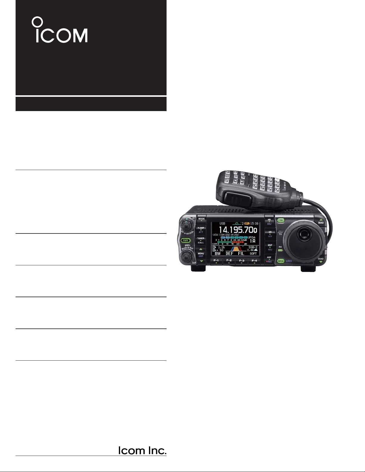
HF/VHF/UHF
ALL MODE TRANSCEIVER
i7000
INSTRUCTION MANUAL
Page 2
i-1
IMPORTANT
READ THIS INSTRUCTION MANUAL
CAREFULLY
before attempting to operate the
transceiver.
SAVE THIS INSTRUCTION MANUAL. This
manual contains important safety and operating instructions for the IC-7000.
EXPLICIT DEFINITIONS
WORD DEFINITION
R
WARNING
Personal injury, fire hazard or electric
shock may occur.
CAUTION Equipment damage may occur.
NOTE
If disregarded, inconvenience only. No
risk or personal injury, fire or electric
shock.
We understand that you have a choice of many different radios in the market place. We want to take a couple of moments of your time to thank you for making
the IC-7000 your radio of choice, and hope you agree
with Icom’s philosophy of “technology first.” Many
hours of research and development went into the design of your IC-7000.
D
FEATURES
❍ IF DSP features
❍ All mode capability covering 160–0.7 m
(depending on version)
❍ Compact with detachable front panel
❍ ±0.5 ppm of high frequency stability
❍ Boudot RTTY demodulator
❍ Simple band scope function
❍ Selectable SSB transmission passband
width (Each for Higher and lower pass frequency)
❍ Standard voice synthesizer/voice recorder
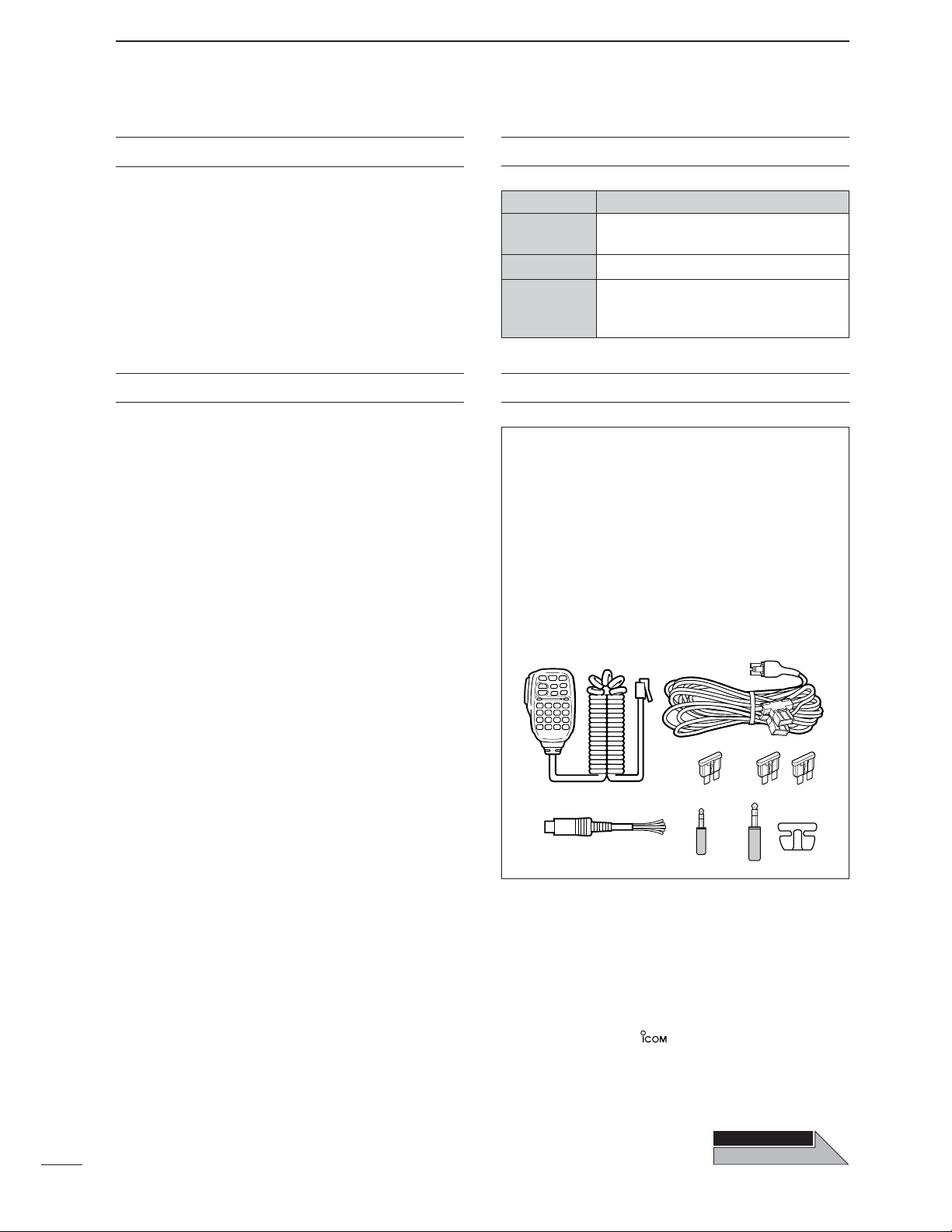
The transceiver comes with the following accessories.
Qty.
q Hand microphone (HM-151) ........................... 1
w DC power cable (OPC-1457) .......................... 1
e Spare fuse (ATC 5 A) ...................................... 1
r Spare fuse (ATC 30 A) .................................... 2
t ACC cable ........................................................1
y 3.5 (d) mm plug ................................................1
u 6.5 (d) mm Electronic keyer plug......................1
i Microphone hanger...........................................1
q
e
t
w
yuri
FOREWORD SUPPLIED ACCESSORIES
Icom, Icom Inc. and the logo are registered trademarks
of Icom Incorporated (Japan) in the United States, the United
Kingdom, Germany, France, Spain, Russia and/or other
countries.
Spurious may be received near the following frequencies.
These are made in the internal circuit and does not indicate a
transceiver malfunction:
52.76497 MHz,
443.03535 MHz
THIS P
THIS P
AGE
AGE
OPEN
Page 3
i-2
SPCH
/LOCK
TUNER
/CALL
XFC
V/M
F-1
F-2
FIL
MODE
GENE
MW
123
456
789
.
0
CE
F-INP
ENT
1.8 3.5 7
10 14 18
21 24 28
50 144 430
Mic element
q
e
w
o
!7!8!9@0@2@3@4 @1
tryu !2
!5
!6
!1!0i
!3
!4
z
c
v
b
n
m
,
.
⁄0
⁄2
⁄3
⁄1
x
Front panel
HM-151
The front panel and HM-151’s panel
descriptions are descrived between
pages 1 to 4, and on page 9, respectively (see the Chapter 1 (Panel description) for more details).
ILLUSTRATIONS
Page 4

i-3
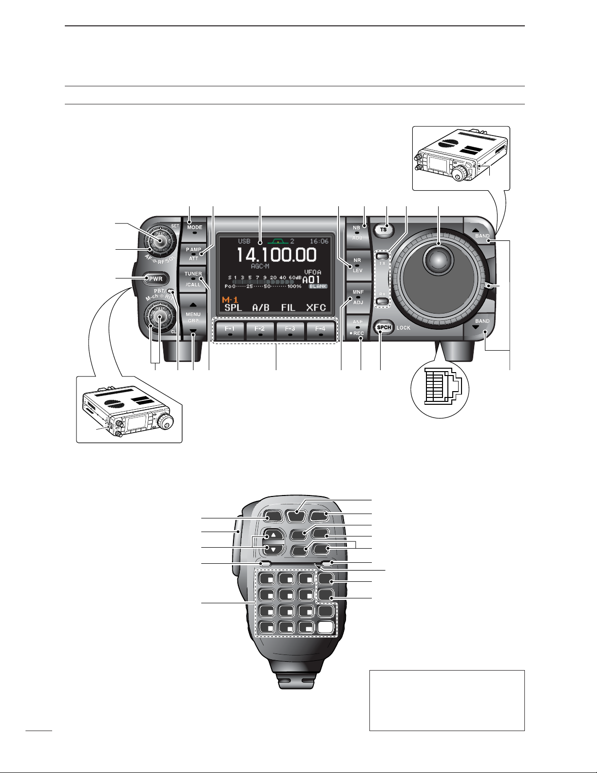
■ Front panel
q AF GAIN CONTROL [AF] (inner control; p. 33)
w RF GAIN CONTROL/SQUELCH CONTROL
[RF/SQL] (outer control; p. 35)
e POWER KEY [PWR] (p. 25)
r FRONT PANEL LATCH (p. 16)
t PASSBAND TUNING/M-ch/RIT CONTROLS
[PBT/M-ch/RIT] (pgs. 75, 79, 88, 102, 106)
y TWIN PBT (M-ch/RIT) INDICATOR
(pgs. 75, 79, 88, 102, 106)
u MENU/GROUP KEYS [MENU/GRP] (p. 153)
i TUNER/CALL KEY [TUNER/CALL]
(pgs. 102, 116)
o MULTI-FUNCTION KEYS [F1]/[F2]/[F3]/[F4]
(pgs. 5–8, 153)
!0 MANUAL NOTCH KEY [MNF/ADJ] (p. 83)
!1 AUTO NOTCH/VOICE RECORDER KEY
[ANF/•REC] (pgs. 82, 95)
!2 SPCH/LOCK KEY [SPCH/LOCK] (pgs. 34, 37)
!3 MICROPHONE CONNECTOR (p. 10)
!4
UP/DOWN (BAND) KEYS
[Y(
BAND
)]/[Z(
BAND
)]
!5 MAIN DIAL TENSION LATCH
!6 HEADPHONE JACK [PHONES] (p. 18)
!7 MAIN DIAL [DIAL]
!8 RECEIVE/TRANSMIT INDICATORS [RX]/[TX]
!9 TUNING STEP KEY [TS] (pgs. 30–32)
@0 NOISE BLANKER KEY [NB/ADJ] (p. 80)
@1 NOISE REDUCTION KEY [NR/LEV] (p. 81)
@2 FUNCTION DISPLAY (p. 13)
@3 PRE AMP/ATTENUATOR KEY [P.AMP/ATT]
(p. 74)
@4 MODE KEY [MODE] (p. 34)
■ Microphone (HM-151)
z SPCH/LOCK KEY [SPCH/LOCK] (p. 34, 37)
x PTT SWITCH [PTT] (p. 37)
c UP/DOWN SWITCHES [Y]/[Z]
v TRANSMIT INDICATOR
b KEYPAD (pgs. 28, 29)
n FILTER SELECTION [FIL] (p. 77)
m MODE KEY [MODE] (p. 34)
, POWER INDICATOR
. PROGRAMMABLE FUNCTION KEYS [F-1]/[F-2]
⁄0 MEMORY WRITE [MW] (pgs. 103, 104)
⁄1 VFO/MEMORY SELECTION [V/M]
(pgs. 27, 102, 109)
⁄2 TRANSMIT FREQUENCY CHECK [XFC]
(pgs. 65, 91)
⁄3 TUNER/CALL KEY [TUNER/CALL]
(pgs. 102, 116)
Page 5

ii
R WARNING RF EXPOSURE! This device emits
Radio Frequency (RF) energy. Extreme caution should be
observed when operating this device. If you have any
questions regarding RF exposure and safety standards
please refer to the Federal Communications Commission
Office of Engineering and Technology’s report on Evaluating Compliance with FCC Guidelines for Human Radio
Frequency Electromagnetic Fields (OET Bulletin 65).
R WARNING HIGH VOLTAGE! NEVER attach an
antenna or internal antenna connector during transmission. This may result in an electrical shock or burn.
R NEVER apply AC to the [DC13.8V] socket on the
transceiver rear panel. This could cause a fire or damage
the transceiver.
R NEVER apply more than 16 V DC, such as a 24 V
battery, to the [DC13.8V] jack on the transceiver rear
panel. This could cause a fire or damage the transceiver.
R NEVER let metal, wire or other objects touch any in-
ternal part or connectors on the rear panel of the transceiver. This may result in an electric shock.
R NEVER connect or use the HM-151 (microphone)
with other transceiver. This could cause damage to the
transceiver. The HM-151 is designed for use with the IC7000 ONLY
NEVER expose the transceiver to rain, snow or any liquids.
AVOID using or placing the transceiver in areas with temperatures below –10°C (+14°F) or above +60°C (+140°F).
Be aware that temperatures on a vehicle’s dashboard can
exceed +80°C (+176°F), resulting in permanent damage
to the transceiver if left there for extended periods.
AVOID placing the transceiver in excessively dusty environments or in direct sunlight.
AVOID placing the transceiver against walls or putting
anything on top of the transceiver. This will obstruct heat
dissipation.
Place unit in a secure place to avoid inadvertent use by
children.
During mobile operation, NEVER place the transceiver
where air bag deployment may be obstructed.
During mobile operation, DO NOT place the transceiver
where hot or cold air blows directly onto it.
During mobile operation, DO NOT operate the transceiver
without running the vehicle’s engine. When the transceiver’s power is ON and your vehicle’s engine is OFF,
the vehicle’s battery will soon become exhausted.
Make sure the transceiver power is OFF before starting
the vehicle. This will avoid possible damage to the transceiver by ignition voltage spikes.
During maritime mobile operation, keep the transceiver
and microphone as far away as possible from the magnetic navigation compass to prevent erroneous indications.
BE CAREFUL! The rear panel will become hot when operating the transceiver continuously for long periods.
BE CAREFUL! If a linear amplifier is connected, set the
transceiver’s RF output power to less than the linear amplifier’s maximum input level, otherwise, the linear amplifier will be damaged.
Use Icom microphones only (supplied or optional). Other
manufacturer’s microphones have different pin assignments, and connection to the IC-7000 may damage the
transceiver.
Beat signals may be heard on some frequencies.
These will occur as a result of circuit construction.
For U.S.A. only
Caution: Changes or modifications to this transceiver,
not expressly approved by Icom Inc., could void your
authority to operate this transceiver under FCC regulations.
PRECAUTIONS
Page 6

iii
IMPORTANT …………………………………………i-1
FOREWORD ………………………………………… i-1
EXPLICIT DEFINITIONS …………………………… i-1
SUPPLIED ACCESSORIES …………………………i-1
ILLUSTRATIONS ……………………………………i-2
■ Front panel ……………………………………… i-3
■ Microphone (HM-151) ………………………… i-3
PRECAUTIONS ………………………………………ii
TABLE OF CONTENTS …………………………… iii
1 PANEL DESCRIPTION …………………1–14
■ Front panel ………………………………………… 1
■ Multi-function keys ……………………………… 5
D Menu M-1 functions …………………………… 5
D Menu M-2 functions …………………………… 5
D Menu M-3 functions …………………………… 5
D Menu S-1 functions …………………………… 7
D Menu S-2 functions …………………………… 7
D Menu S-3 functions …………………………… 8
D Menu G-1 (Scope) functions ………………… 8
■ Microphone (HM-151) …………………………… 9
D Microphone connector ……………………… 10
■ Rear panel ……………………………………… 11
D DATA socket…………………………………… 12
D ACC socket …………………………………… 12
■ Function display ………………………………… 13
2
INSTALLATION AND CONNECTIONS
… 15–24
■ Unpacking ……………………………………… 15
■ Selecting a location……………………………… 15
■ Grounding………………………………………… 15
■ Antennaconnection……………………………… 15
■ Installation ……………………………………… 16
D Single body mounting ………………………… 16
D Stand …………………………………………… 16
D Front panel separation ……………………… 16
D Front panel mounting ………………………… 16
■ Required connections…………………………… 17
■ Advanced connections ………………………… 18
■ Power supply connections……………………… 19
■ Connecting a DC power supply ……………… 19
■ Battery connections …………………………… 19
■ External antenna tuners………………………… 20
■ Linear amplifier connections …………………… 21
■ Connections for CW …………………………… 22
■ Connections for RTTY (FSK) ………………… 23
D When connecting to [ACC] socket ………… 23
D When connecting to [MIC] connector ……… 23
■ Connections for packet ………………………… 24
D When connecting to [DATA] socket ………… 24
D When connecting to [ACC] socket ………… 24
D When connecting to [MIC] connector ……… 24
3 BASIC OPERATION ……………………25–38
■ When first applying power (CPU resetting)…… 25
D Menu resetting (M
-
1) ………………………… 25
■ Initial settings …………………………………… 25
■ VFO description ………………………………… 26
D Differences between VFO and
memory mode ………………………………… 26
■ VFO operation …………………………………… 27
D Selecting VFO A/VFO B……………………… 27
D VFO equalization……………………………… 27
■ Selecting VFO/memory mode ………………… 27
■ Selecting an operating band …………………… 28
D Using the band stacking registers…………… 28
■ Frequency setting ……………………………… 29
D Tuning with the main dial …………………… 29
D Direct frequency entry
with the microphone’s keypad ……………… 29
D Programmable tuning step…………………… 30
D Selecting “kHz” step ………………………… 30
D Selecting 1 Hz or 10 Hz step
(SSB/CW/RTTY only) ………………………… 31
D 1 MHz quick tuning step
(FM/WFM/AM only) …………………………… 31
D
1
⁄4
tuning function (CW/RTTY only) ………… 32
D Auto tuning step function …………………… 33
D Band edge warning beep …………………… 33
■ Volume setting…………………………………… 33
■ Operating mode selection ……………………… 34
■ Voice synthesizer function……………………… 34
■ Squelch and receive (RF) sensitivity ………… 35
■ Meter function …………………………………… 36
D Multi-function meter…………………………… 36
■ Lock functions …………………………………… 37
D Dial lock function ……………………………… 37
D Microphone lock function …………………… 37
■ Basic transmit operation ……………………… 37
D Transmitting …………………………………… 37
D Setting output power ………………………… 38
D Setting microphone gain……………………… 38
4 RECEIVE AND TRANSMIT …………… 39–71
■ Operating SSB…………………………………… 39
D Convenient functions for receive …………… 39
D Convenient functions for transmit …………… 40
D About 5 MHz band operation
(USA version only) …………………………… 40
■ Operating CW …………………………………… 41
D Convenient functions for receive …………… 42
D Convenient functions for transmit …………… 42
D CW reverse mode …………………………… 43
D CW side tone function………………………… 43
D CW pitch control ……………………………… 44
D Electronic CW keyer ………………………… 45
D Memory keyer send menu …………………… 46
D Editing a keyer memory ……………………… 47
D Contest number set mode …………………… 48
1 Number Style ……………………………… 48
2 Count UP Trigger …………………………… 48
3 Present Number …………………………… 48
D Keyer set mode ……………………………… 49
1 Keyer Repeat Time ………………………… 49
2 Dot/Dash Ratio……………………………… 49
3 Rise Time …………………………………… 50
TABLE OF CONTENTS
Page 7

iv
4 Paddle Polarity ……………………………… 50
5 Keyer Type ………………………………… 50
6 MIC U/D Keyer (HM-103) ………………… 50
D Paddle operation
from [MIC] connector ………………………… 50
■ Operating RTTY (FSK) ………………………… 51
D Convenient functions for receive …………… 52
D RTTY reverse mode ………………………… 53
D Twin peak filter………………………………… 53
D Functions for the RTTY decoder indication… 54
D Setting the decoder threshold level ………… 54
D RTTY decode set mode ……………………… 55
1 RTTY Decode USOS ……………………… 55
2 RTTY Decode New Line Code …………… 55
D Pre-setting for using RTTY terminal or TNC 56
■ Operating AM …………………………………… 57
D Convenient functions for receive …………… 57
D Convenient functions for transmit …………… 58
■ Operating FM …………………………………… 59
D Convenient functions for receive …………… 59
D Convenient functions for transmit …………… 59
D Tone squelch operation ……………………… 60
D Tone scan operation ………………………… 61
D DTCS operation ……………………………… 62
■ Repeater operation……………………………… 63
D One-touch repeater function ………………… 63
D Repeater tone frequency …………………… 64
D Transmit frequency monitor check ………… 65
D Auto repeater function ……………………… 65
D Storing a non standard repeater …………… 66
■ 1750 Hz tone burst ……………………………… 67
■ DTMF memory encoder………………………… 67
D DTMF send menu …………………………… 67
D Programming a DTMF code ………………… 68
D DTMF speed…………………………………… 68
■ TV channel operation …………………………… 69
D Convenient functions for receive …………… 69
D Skip channel setting ………………………… 70
D Channel frequency adjustment ……………… 71
5 FUNCTIONS FOR RECEIVE…………… 72–84
■ Simple band scope ……………………………… 72
D Fix mode ……………………………………… 72
D Center mode…………………………………… 73
D Scope set mode ……………………………… 73
1 Max Hold …………………………………… 74
2 Scope Size ………………………………… 74
3 FAST Sweep ………………………………… 74
4 FAST Sweep Sound ……………………… 74
■ Preamp and attenuator ………………………… 74
■ RIT function ……………………………………… 75
■ AGC function …………………………………… 76
D AGC time constant selection ………………… 76
D Setting the AGC time constant ……………… 76
■ IF filter selection ………………………………… 77
D IF filter selection ……………………………… 77
D Filter passband width setting
(SSB/CW/RTTY/AM only) …………………… 78
D IF filter shape (SSB/CW only) ……………… 78
■ Twin PBT operation …………………………… 79
■ Noise blanker …………………………………… 80
D Noise blanker set mode ……………………… 80
1 NB Level …………………………………… 80
2 NB Width …………………………………… 80
■ Noise reduction ………………………………… 81
D Noise reduction set mode …………………… 81
➥ NR Level …………………………………… 81
■ Notch function …………………………………… 82
D Auto notch function …………………………… 82
D Manual notch function………………………… 83
D Manual notch filter set mode ………………… 83
■ Voice squelch control function ………………… 84
■ Meter peak hold function ……………………… 84
6
FUNCTIONS FOR TRANSMIT
………… 85–94
■ VOX function …………………………………… 85
D Adjusting the VOX function ………………… 85
D VOX set mode ………………………………… 86
1 VOX Gain …………………………………… 86
2 Anti-VOX …………………………………… 86
3 VOX Delay ………………………………… 86
■ Transmit filter width setting (SSB only) ……… 86
■ Break-in function ………………………………… 87
D Semi break-in operation ……………………… 87
D Full break-in operation ……………………… 87
■ ∂TX function …………………………………… 88
■ Monitor function ………………………………… 89
■ Speech compressor …………………………… 89
D Compression level setting …………………… 90
➥ COMP Level ……………………………… 90
■ Split frequency operation ……………………… 91
■ Quick split function ……………………………… 92
D Split offset frequency setting ………………… 93
D Quick split setting …………………………… 93
■ Measuring SWR…………………………………… 94
D Spot measurement …………………………… 94
D Plot measurement …………………………… 94
7 VOICE RECORDER FUNCTIONS …… 95–101
■ Digital voice recorder …………………………… 95
■ Recording a received audio ……………………… 95
D Basic recording ……………………………… 95
D One-touch voice recording…………………… 96
■ Playing the recorded contents …………………… 96
■ Erasing the recorded contents…………………… 97
■ Recording a message for transmit ……………… 98
D Recording ……………………………………… 98
D Confirming/Erasing the recorded message… 98
■ Programming a memory name for transmit …… 99
■ Sending a recorded message ………………… 100
D Transmit level setting ……………………… 100
■ Voice set mode…………………………………… 101
D Voice set mode ……………………………… 101
1 Auto Monitor ……………………………… 101
2 MIC Memo ………………………………… 101
TABLE OF CONTENTS
1
2
3
4
5
6
7
8
9
10
11
12
13
14
15
16
17
18
19
20
Page 8

v
8 MEMORY OPERATION ………………102–112
■ Memory channels ……………………………… 102
■ Memory channel selection …………………… 102
■ Memory programming ………………………… 103
D Programming in VFO mode………………… 103
D Programming in memory mode …………… 104
■ Memory channel list …………………………… 105
D Selecting a memory channel
using the memory channel list……………… 105
D Setting a memory channel
as a select memory ………………………… 106
D Selecting a memory bank ………………… 106
D Memory names ……………………………… 107
■ Memory clearing ……………………………… 108
D Memory clearing
using the memory channel list……………… 108
■ Frequency transferring………………………… 109
D Transferring in VFO mode ………………… 109
D Transferring in memory mode ……………… 110
■ Memo pads……………………………………… 111
D Writing frequencies and operating modes
into memo pads ……………………………… 111
D Calling up a frequency from a memo pad … 112
9 SCAN OPERATION ………………… 113–115
■ Scan types ……………………………………… 113
■ Preparation……………………………………… 113
■ Programmed scan operation ………………… 114
■ Memory scan operation ……………………… 114
■ Select memory scan operation ……………… 115
■ Priority watch …………………………………… 115
10 ANTENNA TUNER OPERATION … 116–117
■ Optional AT-180
AUTOMATIC ANTENNA TUNER
operation………………………………………… 116
D Tuner operation ……………………………… 116
D Manual tuning………………………………… 116
■ Optional AH-4
AUTOMATIC ANTENNA TUNER
operation………………………………………… 117
D AH-4 operation ……………………………… 117
11 PACKET OPERATION …………………… 118
■ Packet operation ……………………………… 118
D Data socket…………………………………… 118
D Adjusting the data speed …………………… 118
D Adjusting the transmit signal output
from the TNC ………………………………… 118
12 CLOCK AND TIMERS……………… 119–121
■ Time set mode ………………………………… 119
D Setting the current year …………………… 120
D Setting the current date …………………… 120
D Setting the current time …………………… 120
D Clock2 function activity……………………… 121
D Clock2 offset setting ………………………… 121
D Auto power OFF activity …………………… 121
13 SET MODE ………………………… 122–138
■ Set mode description ………………………… 122
■ Quick set mode ………………………………… 123
➥ RF Power (all modes) ……………………… 123
➥ MIC Gain (SSB/AM/FM modes)…………… 123
➥ SSB TBW (WIDE) L (SSB mode) ………… 123
➥ SSB TBW (WIDE) H (SSB mode) ………… 124
➥ SSB TBW (MID) L (SSB mode) …………… 124
➥ SSB TBW (MID) H (SSB mode) ………… 124
➥ SSB TBW (NAR) L (SSB mode) ………… 124
➥ SSB TBW (NAR) H (SSB mode) ………… 124
➥ Key Speed (CW mode) …………………… 124
➥ CW Pitch (CW mode) ……………………… 124
➥ Side Tone Level (CW mode) ……………… 125
➥ Side Tone Level Limit (CW mode)………… 125
➥ Twin Peak Filter (RTTY mode) …………… 125
➥ RTTY Mark Frequency (RTTY mode) …… 125
➥ RTTY Shift Width (RTTY mode) ………… 125
➥ RTTY Keying Polarity (RTTY mode)……… 125
■ Display set mode ……………………………… 126
1 Contrast (LCD)……………………………… 126
2 Bright (LCD) ………………………………… 126
3 LCD Unit Bright …………………………… 126
4 LCD Flicker ………………………………… 126
5 Backlight (Switches) ……………………… 126
6 Display Type………………………………… 126
7 Display Font Type ………………………… 127
8 Display Font Size ………………………… 127
9 Meter Peak Hold …………………………… 127
10 Filter Popup (PBT) ………………………… 127
11 Filter Popup (FIL)…………………………… 127
12 1 Hz Mode Popup ………………………… 127
13 Scope CENTER/FIX Popup ……………… 127
14 TV Popup (CH Up/Down) ………………… 128
15 TV Popup (P.AMP/ATT) …………………… 128
16 Voice TX Name Display …………………… 128
17 Keyer Memory Display …………………… 128
18 DTMF Memory Display …………………… 128
19 External Display …………………………… 128
20 Opening Message ………………………… 128
21 My Call ……………………………………… 129
22 Power ON Check…………………………… 129
■ Miscellaneous (others) set mode …………… 130
1 Monitor ……………………………………… 130
2 Monitor Level ……………………………… 130
3 Beep (Confirmation) ……………………… 130
4 Beep (Band edge) ………………………… 130
5 Beep Level ………………………………… 130
6 Beep Level Limit …………………………… 130
7 RF/SQL Control …………………………… 131
8 Quick SPLIT ………………………………… 131
9 SPLIT Offset………………………………… 131
10 SPLIT LOCK………………………………… 131
11 DUP Offset HF ……………………………… 131
12 DUP Offset 50M …………………………… 131
13 DUP Offset 144M ………………………… 131
14 DUP Offset 430M ………………………… 131
15 One Touch Repeater ……………………… 132
TABLE OF CONTENTS
Page 9

vi
16 Auto Repeater ……………………………… 132
17 Tuner (Auto Start) ………………………… 132
18 Tuner (PTT start) …………………………… 133
19 [TUNER] Switch …………………………… 133
20 VSEND Select ……………………………… 133
21 SPEECH level ……………………………… 133
22 SPEECH Language ……………………… 133
23 SPEECH Speed …………………………… 133
24 SPEECH S-Level ………………………… 134
25 SPEECH [MODE] Switch ………………… 134
26 Memopad Numbers ……………………… 134
27 SCAN Speed ……………………………… 134
28 SCAN Resume …………………………… 134
29 MAIN DIAL Auto TS ……………………… 134
30 HM-151 [F-1] ……………………………… 135
31 HM-151 [F-2] ……………………………… 135
32 MIC Up/Down Speed ……………………… 135
33 Quick RIT/∂TX Clear ……………………… 135
34 SSB/CW Synchronous Tuning …………… 135
35 CW Normal Side …………………………… 136
36 VOICE 1st Menu ………………………… 136
37 KEYER 1st Menu ………………………… 136
38 DTMF 1st Menu …………………………… 136
39 Mode Select (SSB) ………………………… 136
40 Mode Select (CW) ………………………… 136
41 Mode Select (RTTY) ……………………… 136
42 Mode Select (AM) ………………………… 137
43 Mode Select (FM) ………………………… 137
44 Mode Select (WFM) ……………………… 137
45 External Keypad (VOICE) ………………… 137
46 External Keypad (KEYER)………………… 137
47 Front Keypad Type ………………………… 138
48 CI-V Baud Rate …………………………… 138
49 CI-V Address ……………………………… 138
50 CI-V Transceive …………………………… 138
51 REF Adjust ………………………………… 138
14 MAINTENANCE ………………………… 139
■ Fuse replacement……………………………… 139
■ Memory backup………………………………… 139
■ Cleaning ………………………………………… 139
15 TROUBLESHOOTING …………… 140–141
16 OPTIONAL UNITS SETTING ……… 142–143
■ MB-106
CARRYING HANDLE
…………………… 142
■ AT-180 internal switch description …………… 143
17 CONTROL COMMAND …………… 144–148
■ Remote jack (CI-V) information ……………… 144
D CI-V connection example …………………… 144
D Data format …………………………………… 144
D
Command table ……………………………… 144
D To send/read memory contents …………… 148
D Band stacking register ……………………… 148
D Codes for memory keyer contents ………… 148
D Character’s code for my call ……………… 149
D Codes for memory name contents ………… 149
D Split/Duplex frequency setting……………… 149
D Repeater tone/tone squelch frequency
setting ………………………………………… 149
D
DTCS code and polarity setting
…………… 149
18 SPECIFICATIONS ………………………… 150
■ General ………………………………………… 150
■ Transmitter……………………………………… 150
■ Receiver ………………………………………… 150
19 OPTIONS …………………………… 151–152
20 MENU GUIDE ………………………153–154
21 ABOUT CE ………………………… 155–156
TABLE OF CONTENTS
1
2
3
4
5
6
7
8
9
10
11
12
13
14
15
16
17
18
19
20
Page 10
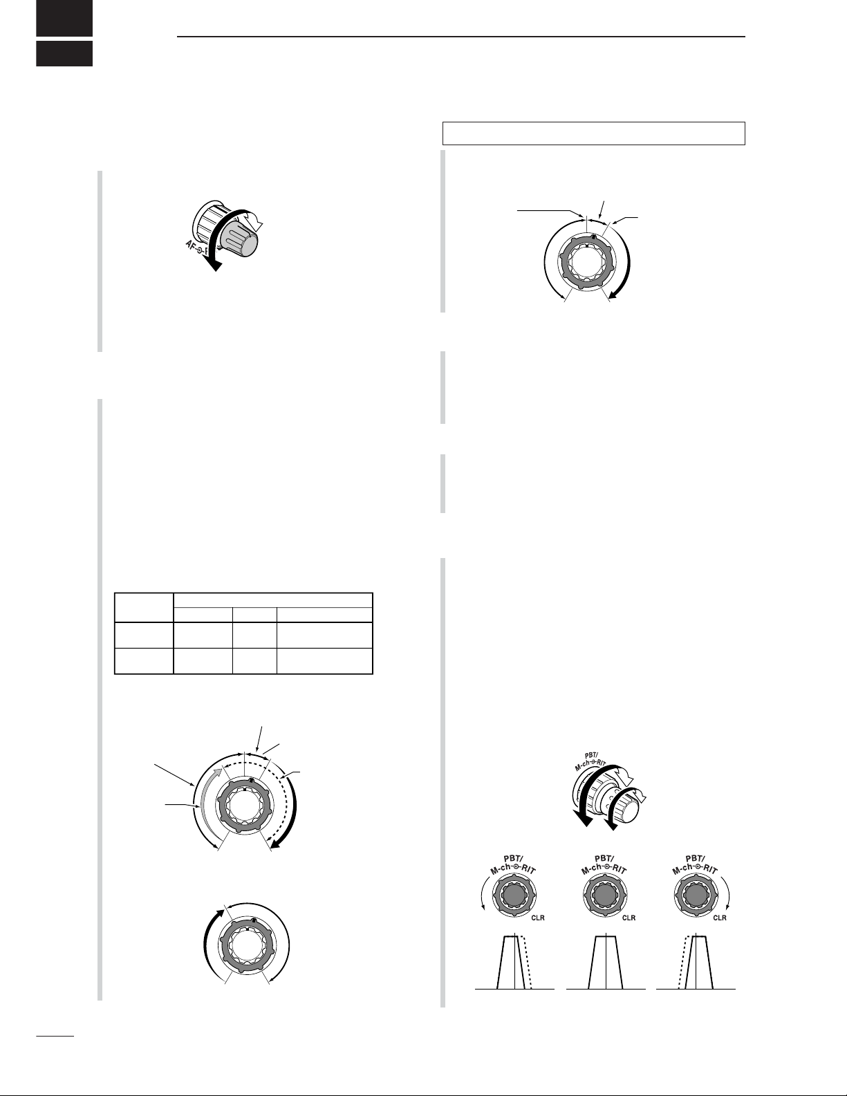
q AF GAIN CONTROL [AF(
SET
)] (inner control; p. 33)
➥ Rotate to vary the audio output level from the
speaker or headphones.
Push momentarily to enter the set mode menu.
•Push again to exit the set mode menu.
➥ Push and hold for 1 sec. to toggle between the
frequency display mode or TV mode.
w RF GAIN CONTROL/SQUELCH CONTROL
[RF/SQL] (outer control; p. 35)
Adjusts the RF gain and squelch threshold level.
The squelch, when closed, mutes the speaker or
headphones when no signal is received, reducing
noise.
•The squelch is particularly effective for FM and WFM
modes. It is also available in other modes.
•12 to 1 o’clock position is recommended for any setting
of the [RF/SQL] control.
•The control can be set to ‘Auto’ (RF gain control in SSB,
CW and RTTY; squelch control in AM, FM and WFM) or
squelch control (RF gain is fixed at maximum) in the miscellaneous (others) set mode as follows. (p. 131)
• When functioning as RF gain/squelch control
•When functioning as RF gain control
(Squelch is fixed open; SSB, CW, RTTY only)
•When functioning as squelch control
(RF gain is fixed at maximum.)
e POWER KEY [PWR] (p. 25)
➥ While transceiver’s power is OFF, push to turn the
power ON.
•Turn the DC power supply ON in advance.
➥ While transceiver’s power is ON, push and hold
for 1 sec. to turn the power OFF.
r FRONT PANEL LATCH (p. 16)
Pull away from the transceiver (towards yourself
when looking at the front of the transceiver) to detach the front panel from the main body of the transceiver.
t PASSBAND TUNING/M-ch/RIT CONTROLS
[PBT/M-ch/RIT]
➥ Push inner control to toggle the twin Passband
Tuning (PBT) or memory channel/RIT function
ON and OFF.
➥ While Twin PBT is selected (p. 79):
●
●
Adjusts the receiver’s DSP filter passband
width.
•Passband width and shift frequency are displayed
on the LCD.
•The default variable range is half of the IF filter
passband width. 25 Hz step is available.
●
●
Push and hold inner control for 1 sec. to return
the PBT to default settings.
Low cutHigh cut Center
+–
PBT1
PBT2
Squelch is
open.
S-meter
squelch
S-meter squelch
threshold
Noise squelch
threshold
(FM/WFM modes)
Lowest threshold Highest threshold
Noise squelch (FM/WFM modes)
Minimum RF gain
Adjustable
range
Maximum RF gain
Recommended level
RF gain
adjustable
range
Maximum
RF gain
S-meter shows
squelch level
Noise squelch (WFM/FM modes)
Squelch is
open.
MODE
SSB, CW
RTTY
AM, FM
WFM
Auto
RF GAIN
SQL
SQL
SET MODE SELECTION
SQL
SQL
RF + SQL
RF + SQL
RF + SQL
Audio outut
decreases
Audio output
increases
1
1
PANEL DESCRIPTION
■ Front panel
See the illustration of the Front panel on page i-2.
Page 11

✔
What is the PBT control?
PBT electronically narrows the IF passband width to reject
interference. This transceiver uses DSP to implement PBT.
➥ While M-ch/RIT is selected:
●
●
Rotate the inner control to select a memory
channel number (p. 102).
●
●
Push inner control for 1 sec. to turn the
RIT/∂TX mode ON (pgs. 75, 88).
•Push [Z(
MENU/GRP
)] to exit the RIT/∂TX mode.
●
●
While the RIT/∂TX mode is OFF:
Rotates outer control to select a memory bank
(p. 106).
●
●
While the RIT/∂TX is ON:
Rotate outer control to shift the receive or
transmit frequency (pgs. 75, 88).
•“ ” or “ ” indicators appear when the RIT or
∂TX function is activate, respectively.
•The shift frequency range is ± 9.999 kHz in 1 Hz
steps (or ±9.99 kHz in 10 Hz steps).
•When the RIT or ∂TX function is ON, push and
hold [F-1
RIT
] or [F-2
∂TX
] for 1 sec. to add or
subtract the frequency shift to the display frequency.
✔
What is the RIT function?
RIT (Receiver Incremental Tuning) shifts the receive frequency without shifting the transmit frequency.
This is useful for fine tuning for stations calling you off frequency or when you prefer to listen to slightly differentsounding voice characteristics, etc.
✔
What is the ∂TX function?
The ∂TX shifts the transmit frequency without shifting the receive frequency. This is useful for simple split frequency operation in CW, etc.
y TWIN PBT (M-ch/RIT) INDICATOR
(pgs. 75, 79, 88, 102)
➥ Indicates the status of [PBT/M-ch/RIT] (t) acti-
vates as the Twin PBT function or memory channel/RIT control.
•Indicator is green when the Twin PBT is selected.
•Indicator is off when the M-ch/RIT is selected.
•Indicator is orange when the RIT or ∂TX function is
activate.
u MENU/GROUP KEYS [MENU/GRP] (p. 153)
➥ Push either key one or more times to select
menus within a menu group (M,SorG(Graphic)).
➥ Push and hold for 1 sec. to select one of the three
menu groups:
M
-
1toM-3,S-1toS-3
and
G-1
(Scope) to
G
-
3
(SWR meter).
i TUNER/CALL KEY [TUNER/CALL]
➥ During HF/50 MHz operation (p. 116):
●
●
Push momentarily to toggle the automatic antenna tuner function ON and OFF.
•An optional antenna tuner must be connected.
• “ ” indicator appears when the tuner is ON.
●
●
Push and hold for 2 sec. to manually tune the
antenna.
•An optional antenna tuner must be connected.
• “ ” indicator appears when the tuner is ON.
➥ During 144/430 MHz operation (p. 102):
Push momentarily to select the call channel (or
return to the previous channel/frequency when
the call channel is already selected).
• “C1” is the 144 MHz call channel and “C2” is the 430
MHz call channel.
o MULTI-FUNCTION KEYS [F-1]/[F-2]/[F-3]/[F-4]
➥ Push to select the function indicated in the LCD
display above these keys. (pgs. 5–8, 153)
•Functions vary depending on the active menu.
Functions appear
2
1
PANEL DESCRIPTION
1
See the illustration of the Front panel on page i-2.
RIT
M-ch
M-ch
Channel
decreases
Channel
increases
Frequency
decreases
Frequency
increases
RIT
Page 12

3
1
PANEL DESCRIPTION
!0 MANUAL NOTCH KEY [MNF/ADJ] (p. 83)
➥ Push momentarily to turn the manual notch func-
tion ON and OFF in SSB, CW and AM modes.
• “ ” appears on the display when the function is activated.
➥ Push and hold for 1 sec. to enter the manual
notch filter set mode.
✔
What is the notch function?
The notch function is a narrow DSP filter that removes interfering tones from CW or AM signals while preserving the desired signal's frequency response.
!1 AUTO NOTCH/VOICE RECORDER KEY
[ANF/•REC]
➥ Push momentarily to turn the auto notch function
(ANF) ON and OFF in SSB, AM, FM modes.
(p. 82)
• “ ” appears on the display when the function is activated.
➥ Push and hold for 1 sec. to record the received
signal’s audio. (p. 95)
!2 SPCH/LOCK KEY [SPCH/LOCK]
➥ Push momentarily to have the frequency, etc. an-
nounced by the speech synthesizer. (p. 34)
•The parameters to be announced can be selected in
the miscellaneous (others) set mode. (p. 134)
➥ Push and hold for 1 sec. to toggle the dial lock
function ON and OFF. (p. 37)
•The dial lock function electronically locks the main
dial.
• “ ” appears while the dial lock function is activate.
!3 MICROPHONE CONNECTOR (p. 10)
Modular-type microphone connector—Accepts the
supplied microphone (HM-151).
•The optional OPC-589 can be used to connect an 8-pin
microphone such as the SM-20, if desired.
•A microphone connector is also available on the rear
panel. DO NOT connect 2 microphones simultaneously.
!4
UP/DOWN (BAND) KEYS
[Y(
BAND
)]/[Z(
BAND
)]
➥ Push momentarily to select a frequency band or
TV channel.
➥ Push and hold
[Y(
BAND
)]
for 1 sec. to toggle the
simple band scope display ON and OFF.
➥ Push and hold
[Z(
BAND
)]
for 1 sec. to toggle the
multi-function meter display ON and OFF.
!5 MAIN DIAL TENSION LATCH
Selects the main dial drag.
•Three positions are available. Upper setting turns on
clicks as the dial is turned..
!6 HEADPHONE JACK [PHONES] (p. 18)
Accepts headphones with 8–16 impedance.
•When headphones are connected, no receive audio
comes from the speaker.
•When the PHONES/SPEAKER switch on the back of the
front panel is set to the [SPEAKER] position, an external
speaker can be used instead of headphones. This is
convenient for mobile or outdoor operation.
!7 MAIN DIAL [DIAL]
Changes the displayed frequency and selects values for selected set mode items, etc.
!8 RECEIVE/TRANSMIT INDICATORS [RX]/[TX]
➥[RX]: Lights green in receive mode and when
squelch is open.
➥[TX]: Lights red while transmitting.
Back of the front panel
See the illustration of the Front panel on page i-2.
Page 13
4
1
PANEL DESCRIPTION
1
!9 TUNING STEP KEY [TS] (pgs. 30–32)
➥ While in SSB/CW/RTTY modes, push momentar-
ily to turn the programmable tuning step ON and
OFF. While in AM/FM/WFM modes, push momentarily to toggle the programmable tuning step
and 1 MHz quick tuning step.
•While the programmable tuning step indicator is displayed, the frequency can be changed in programmed
kHz steps.
•0.01 (AM/FM/WFM mode only), 0.1, 1, 5, 9, 10, 12.5,
20, 25 and 100 kHz tuning steps are available.
•A MHz quick tuning step is only available in AM, FM
and WFM modes.
➥ While programmable tuning steps are OFF, turns
the 1 Hz step ON and OFF when pushed and
held for 1 sec.
•1 and 10 Hz steps are only available in SSB, CW and
RTTY modes.
•1 Hz indication appears, and the frequency can be
changed in 1 Hz steps.
➥ While the programmable tuning step is ON, en-
ters the tuning step selection mode when pushed
and held for 1 sec.
@0 NOISE BLANKER KEY [NB/ADJ] (p. 80)
➥ Push momentarily to turn the noise blanker ON
and OFF. The noise blanker reduces pulse-type
noise such as that generated by automobile ignition systems. This function does not work on nonpulse noise or in WFM mode.
• “ ” appears when the noise blanker is ON.
➥ Push and hold for 1 sec. to enter the noise
blanker set mode.
@1 NOISE REDUCTION KEY [NR/LEV] (p. 81)
➥ Push momentarily to turn DSP noise reduction
ON and OFF.
• “ ” appears on the display when the function is activated.
➥ Push and hold for 1 sec. to enter the DSP noise
reduction level.
@2 FUNCTION DISPLAY
Shows the operating frequency, function key menus,
simple band scope display, selected memory channel, receiving TV channel, etc. See p. 13 for details.
@3 PRE AMP/ATTENUATOR KEY [P.AMP/ATT]
(p. 74)
➥ Push momentarily to turn the preamp ON or OFF.
•“ ” indicator appears when the preamp is activated.
➥ Push and hold for 1 sec. to turn the 12 dB attenu-
ator ON; push momentarily to turn the attenuator
OFF.
• “ ” indicator appears when the attenuator is activated.
✔
What is the preamp?
The preamp amplifies signals in the receiver front end (input)
circuit to improve the S/N ratio and sensitivity. Turn ON
‘P.AMP’ when receiving weak signals.
✔
What is the attenuator?
The attenuator prevents a strong undesired signal near the
desired frequency or near your location, such as from a
broadcast station, from causing distortion or spurious signals.
@4 MODE KEY [MODE] (p. 34)
➥ Push momentarily to cycle through the operating
modes:
USB/LSB ➧ CW/CW-R ➧
RTTY/RTTY-R ➧ AM/FM/WFM
➥ Push and hold for 1 sec. to toggle the following
operating modes:
USB ↔ LSB
CW ↔ CW-R
RTTY ↔ RTTY-R
AM → FM → WFM → AM, etc
OPERATING MODE SELECTION
Push
momentarily
Push and hold
for 1 sec.
USB LSB
AM FM WFM
CW CW-R
RTTY-R
RTTY
See the illustration of the Front panel on page i-2.
Programmable tuning step indicator
Page 14
5
1
PANEL DESCRIPTION
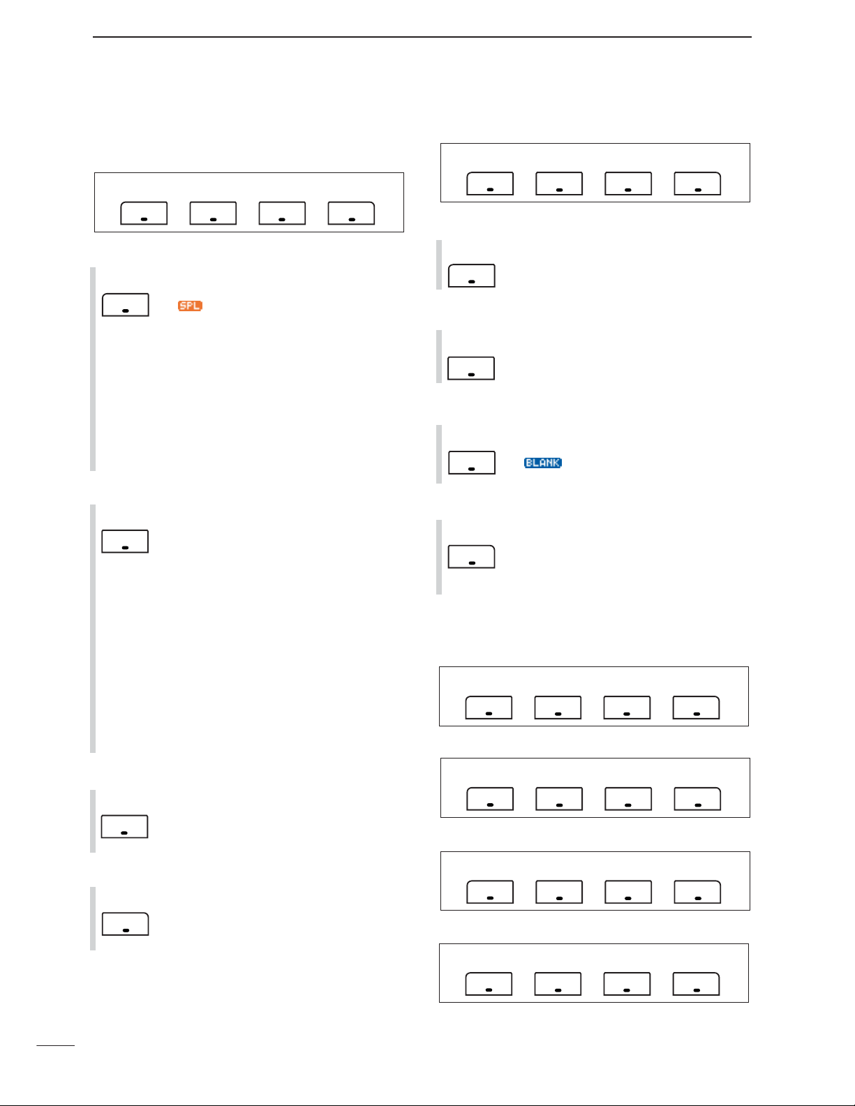
■ Multi-function keys
D Menu M-1 functions
SPLIT OPERATION
➥ Push momentarily to toggle the split func-
tion ON and OFF. (p. 91)
• “”and transmit frequency appear when
the split function is ON.
➥ Push and hold for 1 sec. to turn the quick
split function ON. (p. 92)
•The offset frequency must be programmed in
advance using the miscellaneous (others) set
mode. (p. 131)
•The offset frequency is shifted from the dis-
played frequency.
•The quick split function can be turned OFF in
the miscellaneous (others) set mode. (p. 131)
VFO A/B SELECTION
➥ Push momentarily to exchange the trans-
mit VFO and receive VFO contents. (p.
27)
➥ Push momentarily to toggle the transmis-
sion VFO and reception VFO during split
operation. (p. 91)
➥ Push momentarily to toggle the transmit
and receive frequencies (and modes) of
memory channels when the split function
is turned ON.
➥ Push and hold for 1 sec. to equalize the
frequency and operating mode of the two
VFO’s.
•The lower indicated frequency and operating
mode are equalized to the upper (indicated)
VFO frequency and operating mode.
FILTER SELECTION (p. 77)
➥ Push momentarily to select one of three
IF filter settings.
➥ Push and hold for 1 sec. to enter the filter
set mode.
TRANSMIT FREQUENCY CHECK (pgs. 65, 91)
Monitors the transmit frequency when
pushed and held.
•While pushing this key, the transmit fre-
quency can be changed with [DIAL].
D Menu M-2 functions
MEMORY MENU (p. 105)
Push momentarily to indicate the memory
frequency and modes.
•Memory list indication is available.
MEMORY WRITE (pgs. 103, 104)
Push and hold for 1 sec. to store the selected readout frequency and operating
mode into the displayed memory channel.
MEMORY CLEAR (p. 108)
Push and hold for 1 sec. to clear the se-
lected memory channel contents.
• “ ” appears.
VFO/MEMORY SELECTION
➥ Push momentarily to toggle VFO and
memory modes. (pgs. 27, 102)
➥ Push and hold for 1 sec. to transfer the
selected memory channel to the currently
displayed VFO. (p. 109)
D Menu M-3 functions
DURING SSB OPERATION:
DURING CW OPERATION:
DURING RTTY OPERATION:
DURING AM OPERATION:
F-1 F-2 F-3 F-4
VOX AGC
SPL A/B FIL XFC
F-1 F-2 F-3 F-4
SPL
F-1
A/B
F-2
MWMEM V/M
F-1 F-2 F-3 F-4
MEM
F-1
MW
F-2
MCL
F-3
V/M
F-4
F-1 F-2 F-3 F-4
MCL
TBWVOX COM AGC
FIL
F-3
XFC
F-4
1/4BRK AGC
F-1 F-2 F-3 F-4
1/4 AGC
F-1 F-2 F-3 F-4
Page 15
6
1
PANEL DESCRIPTION
1
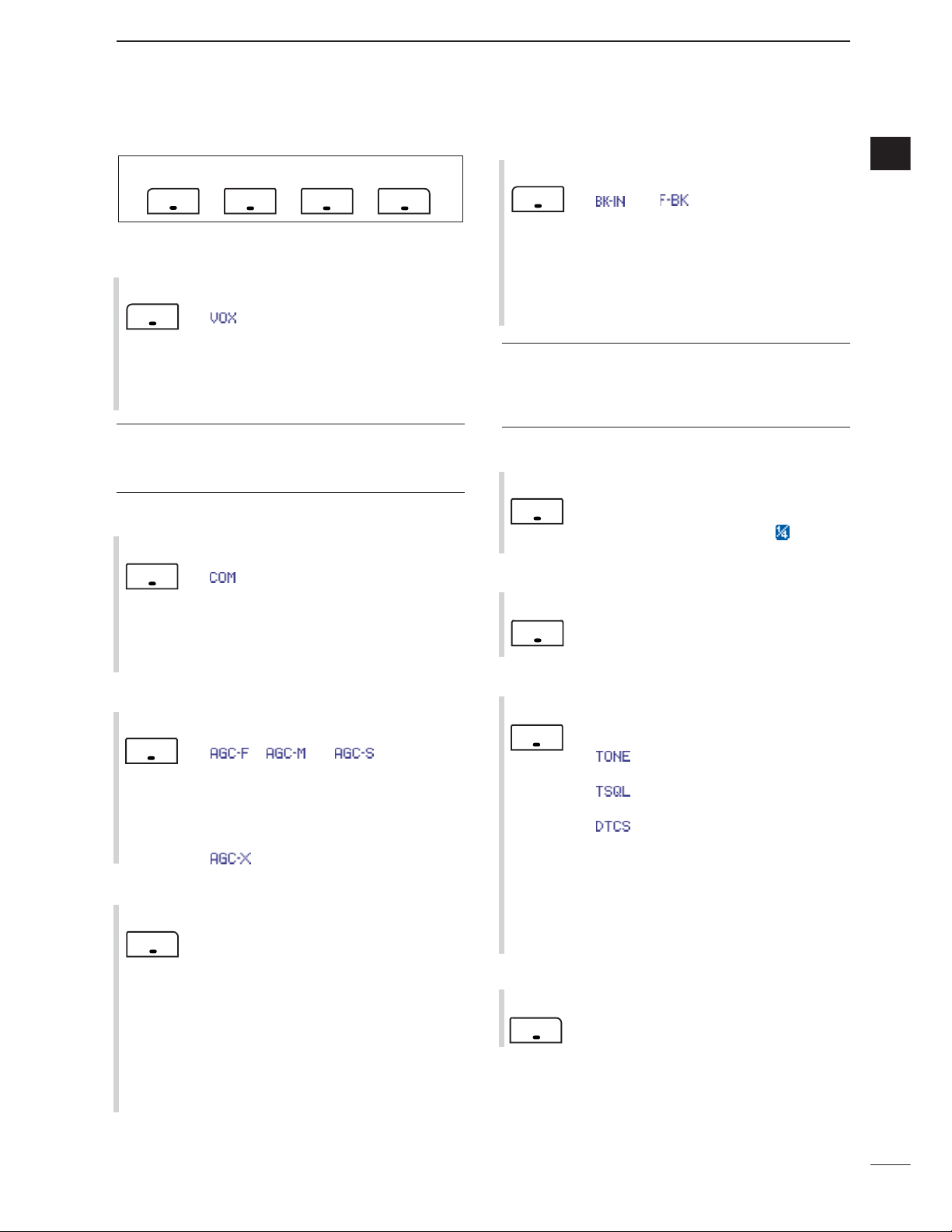
DURING FM/WFM OPERATIONS:
VOX FUNCTION (p. 85)
➥ Push momentarily to toggle the VOX func-
tion ON and OFF.
•“ ” appears when the VOX function is
ON.
➥ Push and hold for 1 sec. to enter the VOX
set mode.
•The VOX gain, ANTI-VOX, VOX delay and
VOX gain can be set in VOX set mode.
✔
What is the VOX function?
The VOX function (voice operated transmission) activates
the transmitter when you speak into the microphone; then,
automatically returns to receive when you stop speaking.
SPEECH COMPRESSOR (p. 89)
➥ Push momentarily to toggle the speech
compressor ON and OFF.
•“ ” appears when the speech compressor is ON.
➥ Push and hold for 1 sec. to enter the com-
pression level set mode.
•Speech compression can be adjusted in
compression level set mode.
AGC (p. 76)
➥ Push to change the time constant of the
AGC circuit.
• “ ,” “ ” or “ ” appears when
the fast time constant, middle time constant
or slow time constant is selected, respectively.
➥ Push and hold for 1 sec. to enter the AGC
set mode.
• “ ” (OFF) can be selected.
TBW (p. 86)
➥ Push momentarily to indicate the selected
TX filter width.
• The popup indicator appears.
➥ Push and hold for 1 sec. to toggle the TX
filter width between narrow, middle or
wide.
•The following filters are specified as the de-
fault. Each filter width can be set in the quick
set mode. (pgs. 123, 124)
WIDE : 100 Hz to 2900 Hz
MID : 300 Hz to 2700 Hz
NAR : 500 Hz to 2500 Hz
BREAK-IN FUNCTION (p. 87)
➥ Push momentarily to select semi-break-in,
full break-in (QSK) and break-in OFF.
•“ ” or “ ” appears when selecting
semi break-in or full break-in, respectively.
•An external switch, such as a foot switch,
must be connected to the ACC socket (pin 3,
pin 7 or RTTY SEND—see p. 23) if break-in
is turned OFF.
➥ Push and hold for 1 sec. to enter the
break-in delay time set mode.
✔
What is the break-in function?
Full break-in (QSK) activates the receiver between transmitted dots and dashes. This is useful when operating in nets,
or during DX pile-ups and during contests, when “fast responses” are common.
1/4 FUNCTION
Push to toggle the 1/4-speed tuning function ON and OFF in CW and RTTY
modes.
•When the 1⁄
4 function is ON, “ ” appears
and fine tuning can be used.
DUPLEX FUNCTION (p. 63)
➥ Push to select the duplex transmit offset
direction or turn the function OFF.
➥ Push and hold for 1 sec. to turn the one-
touch repeater function ON/OFF.
FM TONE OPERATION
➥ Push momentarily to set the subaudible
tone encoder for repeater use, tone
squelch function, DTCS and OFF.
•“ ” appears when the repeater tone
function is ON. (p. 63)
• “ ” appears when the tone squelch func-
tion is ON. (p. 60)
•“ ” appears when the DTCS squelch
function is ON. (p. 62)
➥ Push and hold for 1 sec. to enter the tone
frequency or DTCS code set mode. (pgs.
60, 62)
•Tone scan function is also available. (p. 61)
➥ Push and hold to transmit a 1750 Hz tone
when pushing and holding [PTT]. (p. 67)
9600 MODE
Push to turn the 9600 bps data transmission mode ON and OFF. (p. 118)
F-4
9600
F-3
TON
F-2
DUP
F-2
1/4
F-1
BRK
F-4
TBW
F-3
AGC
F-2
COM
F-1
VOX
F-1 F-2 F-3 F-4
VOX DUP TON
9600
Page 16
7
1
PANEL DESCRIPTION
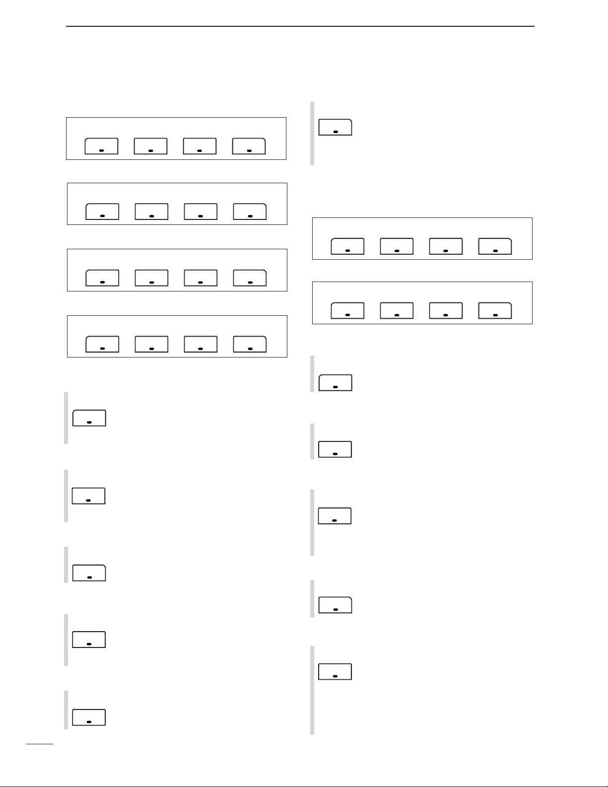
D Menu S-1 functions
DURING SSB/AM OPERATION:
DURING CW OPERATION:
DURING RTTY OPERATION:
DURING FM/WFM OPERATIONS:
VO (p. 95)
Push to enter the voice recorder mode.
•The voice TX/RX menu or voice root menu
appears depending on the “
VOICE 1st
Menu
” setting in the miscellaneous (others)
set mode. (p. 136)
METER SELECTION (p. 36)
Push to select the type of metering displayed (during transmit) on the display.
•Power, SWR, ALC or COMP metering can be
selected.
•Only an S-meter is available during receive.
VOICE SQUELCH CONTROL (p. 84)
Push to toggle the voice squelch control
function ON and OFF.
KEYER OPERATION (p. 45)
Push to enter the memory keyer mode.
•The keyer send menu or keyer root menu appears depending on the “
KEYER 1st
Menu
” setting in the miscellaneous (others)
set mode.(p. 136)
RTTY DECODER FUNCTION (p. 54)
Push to toggle the RTTY decoder display
ON and OFF.
•RTTY decoder screen appears.
DTMF OPERATION
Push to enter DTMF memory mode.
(p. 67)
•The DTMF send menu or DTMF root menu
appears depending on the “
DTMF 1st
Menu
” setting in the miscellaneous (others)
set mode. (p. 136)
D Menu S-2 functions
DURING VFO MODE:
DURING MEMORY MODE:
SCAN (pgs. 113–115)
➥ Push momentarily to start or stop the
scan function.
PRIORITY WATCH (p. 115)
Push to start or stop priority watch.
VFO/MEMORY SELECTION
➥ Push momentarily to toggle VFO and
memory modes. (pgs. 27, 102)
➥ Push and hold for 1 sec. to transfer the
frequency and operating mode in the se-
lected memory channel to the currently
displayed VFO. (p. 109)
VOICE SQUELCH CONTROL (p. 84)
Push to toggle the voice squelch control
function ON and OFF.
SELECT SCAN
➥ Push momentarily to toggle the select
scan settings ON and OFF for the selected memory channel. (pgs. 106, 115)
➥ Push and hold for 2 sec. to clear all select
scan setting. (p. 115)
➥ While scanning, push to toggle the se-
lected memory scan ON and OFF.
(p. 115)
F-2
SEL
F-4
VSC
F-3
V/M
F-2
PRI
F-1
SCN
F-1 F-2 F-3 F-4
VSCSCN SEL V/M
F-1 F-2 F-3 F-4
F-1 F-2 F-3 F-4
F-1 F-2 F-3 F-4
F-1 F-2 F-3 F-4
VO
F-1
VSCVO MET
VSCVO KEY MET
VSCVO DEC MET
VSCVO DTM MET
DTM
F-4
F-1 F-2 F-3 F-4
VSCSCN PRI V/M
MET
F-3
VSC
F-4
KEY
F-2
DEC
F-2
Page 17
8
1
PANEL DESCRIPTION
1
D Menu S-3 functions
MEMORY WRITE (pgs. 103, 104)
Push and hold for 1 sec. to store the displayed VFO frequency and operating
mode into the selected memory channel.
MEMO PAD WRITE (p. 111)
Push to store the displayed VFO frequency and operating mode into a memo
pad.
MEMO PAD READ (p. 112)
Push to call up a memo pad.
✔
What is the memo pad function?
The memo pad function stores the frequency and operating
mode for easy recall. The memo pads are separate from the
usual memory channels. The default number of memo pads
is 5, however, this can be increased to 10 in the miscellaneous (others) set mode, if desired. (p. 134)
D Menu G-1 (Scope) functions
SWEEP STEPS (pgs. 72, 73)
➥ Push momentarily to change the sweep
step size.
•Available steps are ±10, 25, 50, 100 and 250
kHz.
➥ Push and hold for 1 sec. to change the
sweep steps to ±10 kHz.
PEAK HOLD (pgs. 72, 73)
➥ Push to freeze the current simple band
scope display.
•“H” indicator appears while the function is in
use.
➥ Push and hold for 1 sec. to clear the peak
levels.
•Peak levels are displayed in the background
on the simple band scope display. The peak
hold function can be disabled in the scope
set mode. (p. 73)
FIX/CENTER SELECTION (pgs. 72, 73)
➥ Push to toggle the simple band scope fix
mode and center mode.
•Fix mode:
Rotating [DIAL] leaves the marker centered.
•Center mode:
Rotating [DIAL] moves the edge frequencies.
➥ While fix mode operation, push and hold
for 1 sec. to set the displayed frequency
to that of the marker.
SWEEP SPEED
➥ Push momentarily to change the sweep
speed between Fast and Slow. (pgs. 72,
73)
➥ Push and hold for 1 sec. to enter the
scope set mode. (p. 73)
F-4
SPD
F-3
FIX
F-2
HLD
F-1
SPN
F-1 F-2 F-3 F-4
SPN HLD FIX SPD
MW MPW MPR
F-1 F-2 F-3 F-4
MW
F-1
MPW
F-2
MPR
F-3
Page 18

9
1
PANEL DESCRIPTION
z SPCH/LOCK KEY [SPCH/LOCK]
➥ Push momentarily to have the frequency, etc. an-
nounced by the speech synthesizer. (p. 34)
•The parameters to be announced can be selected in
the miscellaneous (others) set mode. (p. 134)
➥ Push and hold for 1 sec. to toggle the microphone
lock function ON and OFF. (p. 37)
x PTT SWITCH [PTT] (p. 37)
Push and hold to transmit; release to receive.
c UP/DOWN SWITCHES [Y]/[Z]
Change the operating frequency.
•Push and hold to change the frequency repeatedly.
•Tuning step size is 50 Hz if no TS indicator is displayed.
v TRANSMIT INDICATOR
Lights red while transmitting.
b KEYPAD
➥ Pushing a key selects the operating band.
•[(GENE)•] selects the general coverage band.
➥ Pushing the same key 2 or 3 times calls up other
stacked frequencies in the band. (p. 28)
•Icom’s triple band stacking register memorizes 3 frequencies in each band.
➥ After pushing [(F-INP)ENT], enter a numeric fre-
quency, followed by pressing [(F-INP)ENT]
again. (p. 29)
•e.g. to enter 14.195 MHz, push [(F-INP)ENT] [1] [4]
[•] [1] [9] [5] [(F-INP)ENT].
n FILTER SELECTION [FIL] (p. 77)
➥ Push momentarily to select one of three IF filter
settings.
➥ Push and hold for 1 sec. to enter the filter set
mode.
m MODE KEY [MODE] (p. 34)
➥ Push momentarily to cycle through the operating
modes:
USB/LSB ➧ CW/CW-R ➧
RTTY/RTTY-R ➧ AM/FM/WFM
➥ Push and hold for 1 sec. to toggle the following
operating modes:
USB ↔ LSB
CW ↔ CW-R
RTTY ↔ RTTY-R
AM → FM → WFM → AM, etc
, POWER INDICATOR
Lights green while transceiver power is ON.
. PROGRAMMABLE FUNCTION KEYS [F-1]/[F-2]
Program and perform a selected function.
•The functions can be assigned in the miscellaneous (others) set mode (p. 135). The default settings for [F-1] and
[F-2] are “MPW” and “MPR,” respectively.
⁄0 MEMORY WRITE [MW] (pgs. 103, 104)
Push and hold for 1 sec. to store the displayed VFO
frequency and operating mode into the displayed
memory channel.
⁄1 VFO/MEMORY SELECTION [V/M]
➥ Push momentarily to toggle VFO and memory
modes. (pgs. 27, 102)
➥ Push and hold for 1 sec. to transfer the selected
memory channel to the currently displayed VFO.
(p. 109)
⁄2 TRANSMIT FREQUENCY CHECK [XFC]
(pgs. 65, 91)
Monitors the transmit frequency when pushed and
held.
•While pushing this key, the transmit frequency can be
changed with [DIAL].
⁄3 TUNER/CALL KEY [TUNER/CALL]
➥ During HF/50 MHz operation (p. 116):
●
●
Push momentarily to toggle the automatic antenna tuner function ON and OFF.
•An optional antenna tuner must be connected.
• “ ” indicator appears when the tuner is ON.
●
●
Push and hold for 2 sec. to manually tune the
antenna.
•An optional antenna tuner must be connected.
• “ ” indicator appears when the tuner is ON.
➥ During 144/430 MHz operation (p. 103):
Push momentarily to select the call channel (or
return to the previous channel/frequency when
the call channel is already selected).
• “C1” is the 144 MHz call channel and “C2” is the 430
MHz call channel.
■ Microphone (HM-151)
Default settings
[F-1] (MPW): Push to store the selected readout
frequency and operating mode into
a memo pad.
[F-2] (MPR): Push to call up a memo pad.
See the illustration of the HM-151 on page i-2.
Page 19
10
1
PANEL DESCRIPTION
1
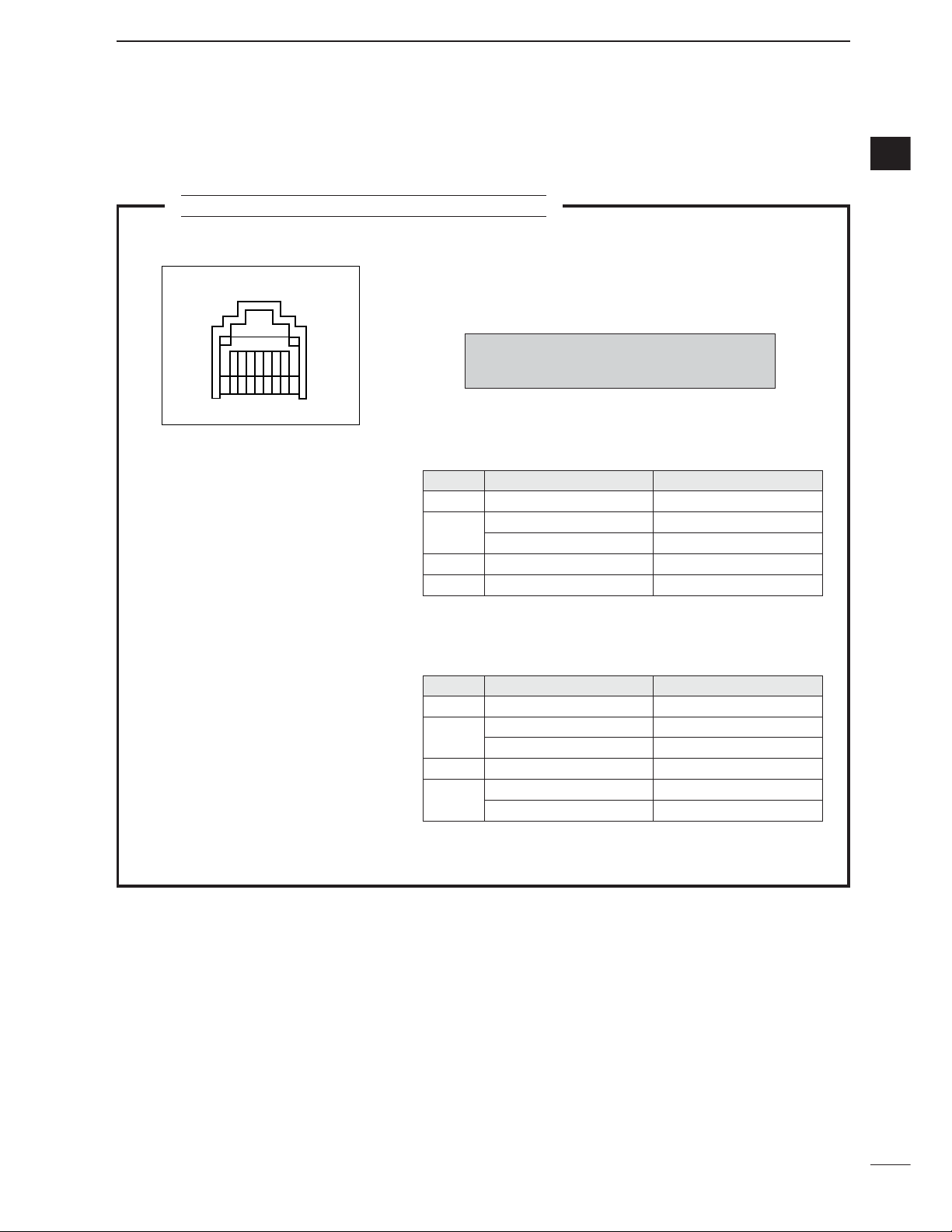
MICROPHONE CONNECTOR INFORMATION
r PTT
y Microphone input
w Frequency up/down
u GND
q +8 V DC output
i DATA IN
t GND (Microphone ground)
e M8V SW
r PTT
y Microphone input
w Frequency up/down
u GND
q +8 V DC output
i Squelch switch
t GND (Microphone ground)
e M8V SW
Rear panel view
12345678
HM-151
HM-103
CAUTION:
DO NOT short pin 1 to ground as
this can damage the internal 8 V regulator.
PIN NO. FUNCTION
DESCRIPTION
1
• When HM-151 is connected
• When HM-103 is connected
3
8
+8 V DC output
Max. 10 mA
2
Frequency up
Ground
Frequency down
Ground through 470
HM-151 connection
Goes to ground to connect
3
HM-151 connection
Open to pin 8 as SQL
HM-151 data
Control signal input
PIN NO. FUNCTION
DESCRIPTION
1 +8 V DC output
Max. 10 mA
2
Frequency up
Ground
Frequency down
Ground through 470
8
Squelch open
“LOW” level
Squelch closed “HIGH” level
D Microphone connector
Page 20
11
1
PANEL DESCRIPTION
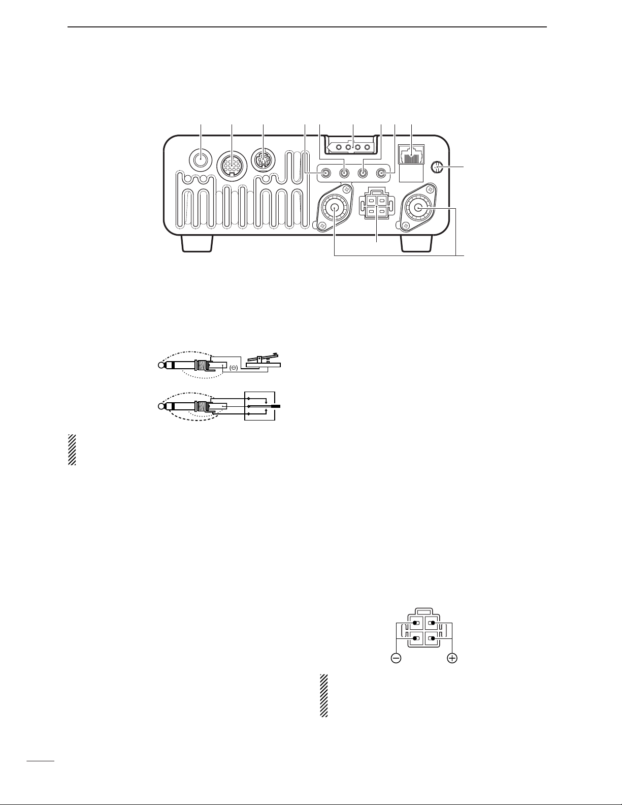
q ELECTRONIC KEYER JACK [KEY] (p. 22)
Accepts a paddle to activate the internal electronic
keyer.
•Selection between the internal electronic keyer and
straight key operation can be made in the keyer set
mode. (p. 50)
If you use an external electronic keyer, make sure
the output voltage of the keyer is less than 0.4 V
when keying the transmitter.
w ACCESSORY SOCKET [ACC] (p. 12)
Enables connection to external equipment such as a
TNC for data communications, a linear amplifier or
an automatic antenna selector/tuner, etc.
•See page at right for socket wiring information.
e DATA SOCKET [DATA] (p. 12)
6-pin mini-DIN socket to connect a TNC (Terminal
Node Controller), etc. for packet operation.
•See page at right for socket wiring information.
r VIDEO OUT JACK [VOUT] (p. 18)
Outputs a video signal.
t CI-V REMOTE CONTROL JACK [REMOTE]
(p. 144)
➥ Designed for use with a personal computer for re-
mote control of the transceiver functions.
➥ Used for transceiver operation with another Icom
CI-V transceiver or receiver.
y TUNER CONTROL SOCKET [TUNER] (p. 20)
Accepts the control cable from an optional AH-4
HF
/50MHz
AUTOMATIC ANTENNA TUNER
.
u
RTTY JACK [RTTY]
(p. 23)
Connects an external terminal unit for RTTY (FSK)
operation.
•The keying polarity, mark/shift frequencies and etc. can
be selected in quick set mode (p. 125).
i EXTERNAL SPEAKER JACK [EXT SP] (p. 18)
Accepts a 4–8 speaker.
o MICROPHONE CONNECTOR [MIC] (p. 17)
Accepts the supplied microphone (connected in parallel with the front panel’s [MIC] connector).
•See p. 2 for microphone notes.
•See p. 10 for microphone connector information.
!0 GROUND TERMINAL [GND] (p. 15)
Connect this terminal to a station or vehicle ground
to prevent electrical shocks, TVI, BCI and other
problems.
!1 ANTENNA CONNECTOR [ANT1], [ANT2] (p. 17)
Accepts a 50 antenna with a PL-259 connector.
•[ANT1] is for connection to an HF/50 MHz antenna.
•[ANT2] is for connection to an 144/430 MHz antenna.
•ANT1 is used below and ANT2 above 60 MHz.
!2 DC POWER SOCKET [DC13.8V] (p. 19)
Accepts 13.8 V DC through the supplied DC power
cable.
NOTE: DO NOT use a cigarette lighter socket as a
power source when operating in a vehicle. The plug
may cause voltage drops and ignition noise may be
superimposed onto transmit or receive audio.
■ Rear panel
qwe yuir to
KEY ACC DATA
()
When connecting
a straight key
(dot)
When connecting
a paddle
(com)
(dash)
MIC
GND
!0
ANT2 ANT1
DC 13.8V
!2
!1
Rear panel view
Page 21
12
1
PANEL DESCRIPTION
1
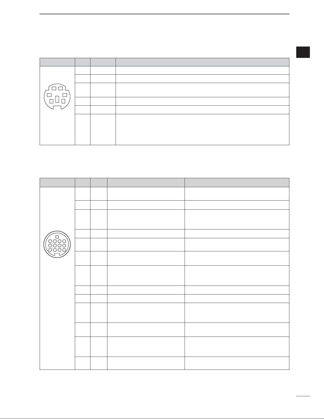
ACC
PIN No.
NAME DESCRIPTION SPECIFICATIONS
1234
8765
9
10 11 12
13
Rear panel view
q brown i gray
w red o white
e orange !0 black
r yellow !1 pink
t green !2 light
blue
y blue
u purple !3 light
green
1 8 V Regulated 8 V output.
Output voltage : 8 V ±0.3 V
Output current : Less than 10 mA
2 GND Connects to ground. ———
Input/output pin.
(HF/50 MHz only) Ground level : –0.5 V to 0.8 V
3
HSEND
Goes to ground when transmitting. Output current : Less than 20 mA
Grounded when transmits. Input current (Tx) : Less than 200 mA
4 BDT Data line for the optional AT-180. ———
5 BAND
Band voltage output.
Output voltage : 0 to 8.0 V
(Varies with amateur band)
6 ALC ALC voltage input.
Control voltage : –4 V to 0 V
Input impedance : More than 10 k
Input/output pin.
(144/430 MHz only) Ground level : –0.5 V to 0.8 V
7
VSEND
Goes to ground when transmitting. Output current : Less than 20 mA
Grounded when transmits. Input current (Tx) : Less than 200 mA
8 13.8 V 13.8 V output when power is ON. Output current : Max. 1 A
9 TKEY Key line for the optional AT-180. ———
“High” level : More than 2.4 V
10 FSKK Controls RTTY keying “Low” level : Less than 0.6 V
Output current : Less than 2 mA
11 MOD
Modulator input.
Input impedance : 10 k
Input level : Approx. 100 mV rms
AF detector output.
Output impedance : 4.7 k
12 AF Fixed level, regardless of [AF]
Output level : 100–300 mV rms
position in
default settings.
13 SQLS
Squelch output. SQL open : Less than 0.3 V/5 mA
Grounded when squelch opens. SQL closed : More than 6.0 V/100 µA
DATA
PIN No.
NAME DESCRIPTION
12
34
56
Rear panel view
1 DATA IN Input terminal for data transmit. (1200 bps: AFSK/9600 bps: G3RUH, GMSK)
2 GND Common ground for DATA IN, DATA OUT and AF OUT.
3 PTT P
PTT terminal for packet operation. Connect to ground to activate the transmitter.
When grounded, microphone input (pin 6) of [MIC] connector will be disconnected.
4 DATA OUT Data out terminal for 9600 bps operation only.
5 AF OUT Data out terminal for 1200 bps operation only.
Squelch out terminal. Becomes ground level when the transceiver receives a signal
which opens the squelch.
6 SQL •To avoid interfering transmissions, connect squelch to the TNC to inhibit transmission
when squelch is open.
• Keep RF gain at a normal level, otherwise a “SQL
”
signal will not be output.
Color refers to the cable strands of the supplied cable.
D DATA socket
D ACC socket
Page 22

13
1
PANEL DESCRIPTION
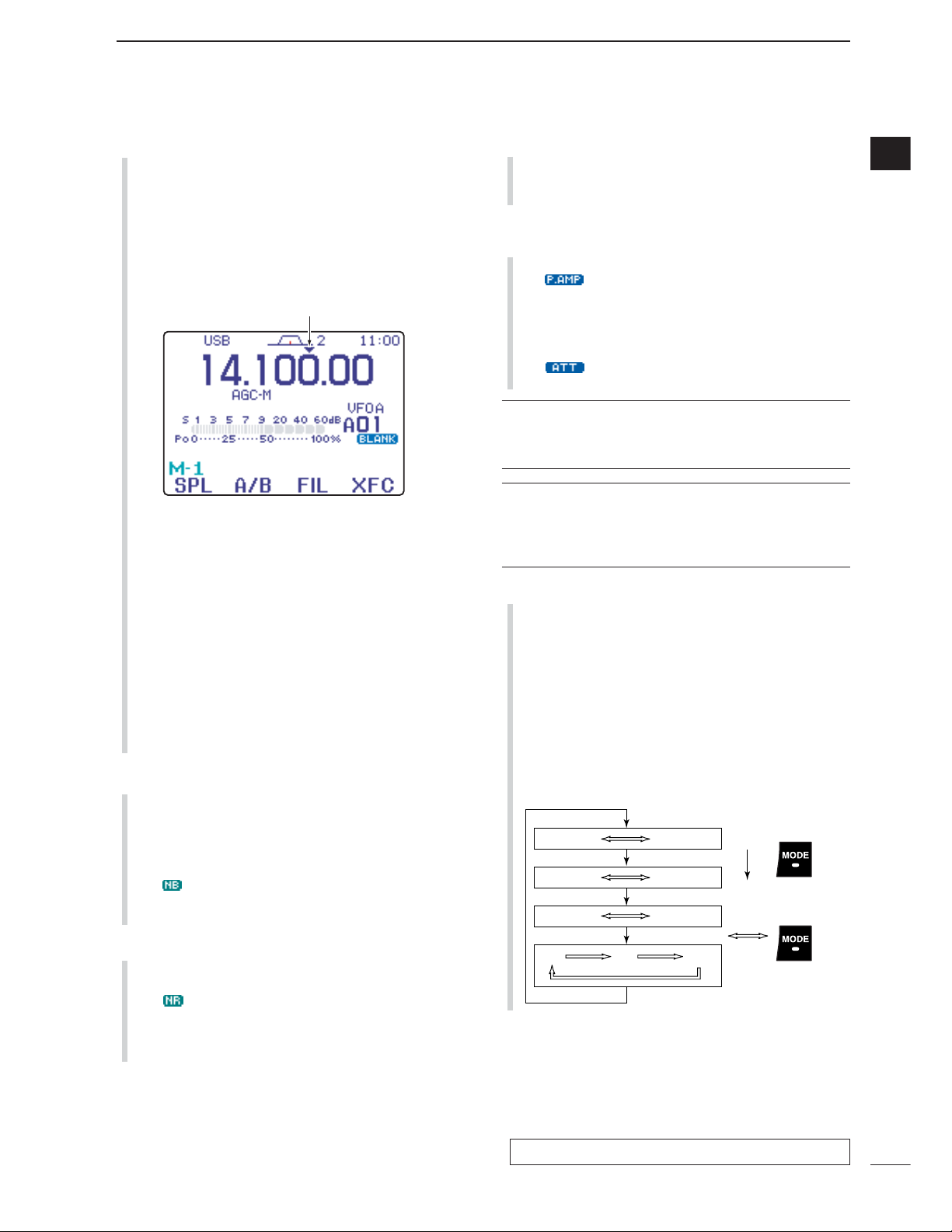
q FREQUENCY READOUT
Shows the operating frequency.
w METER READOUTS
➥ Shows received signal strength while receiving.
➥ Shows either transmit power meter (Po), SWR,
ALC or compression level meter (COM) while
transmitting.
e MULTI-FUNCTION KEY GUIDE
Indicates the function of the multi-function keys.
These alphanumeric readouts show a variety of information such as current functions of the “F” keys
[F-1] to [F-4].
r SPLIT FREQUENCY READOUT
Shows the transmit frequency during split operation.
t BLANK MEMORY INDICATOR
Appears when the displayed memory channel is not
programmed (blank channel).
• This indicator appears both in VFO and memory modes.
y MEMORY CHANNEL READOUT
Shows the selected memory channel or scan edge
channel.
•Memory bank indicator (A to E) appears to the left of
memory channel.
• This indicator appears both in VFO and memory modes.
u VFO/MEMORY INDICATORS
➥VFO A or B appears when VFO mode is selected;
MEMO appears when memory mode is selected.
i VOICE RECODER INDICATORS
REC appears when the digital voice recoder function is activated.
o LOCK INDICATOR
Appears when the dial lock function is activated.
!0 DIRECT FREQUENCY ENTRY INDICATOR (p. 29)
Appears when the transceiver is ready for direct frequency entry.
•This indicator appears when [(F-INP)ENT] key on the
HM-151 is pushed.
!0!2 !1 @4 @2
!5a
o
t
u
y
!9
@0
!5b
!8
!3!4 @3
r
i
@1
e
w
q
!6
!7
■ Function display
ACC 1 ACC 2
q FSKK t AF
w GND y SQLS
e HSEND u 13.8 V
r MOD i ALC
q 8 V t ALC
w GND
y VSEND
e HSEND u 13.8 V
r BAND
1234
88765
9
10 11 12
13
1
2
3
4
7
6
5
1
2
3
4
7
6
5
Connect to ACC socket
• When connecting the ACC conversion cable (OPC-599)
Page 23
14
1
PANEL DESCRIPTION
1
!1 SPLIT INDICATOR
Appears during split opeation.
!2 IF FILTER INDICATOR (p. 77)
Shows the selected IF filter number.
!3 PASSBAND WIDTH INDICATOR (p. 77, 79)
Graphically displays the passband width for twin
PBT operation and center frequency for IF shift operation.
!4 MODE INDICATORS
Shows the selected operating mode.
• “-R” appears when CW reverse or RTTY reverse mode
is selected.
!5 PROGRAMMABLE/1 MHz TUNING STEP
INDICATORS
➥
!5a appears when the 1 MHz quick tuning step is
selected.
➥
!5b appears when the programmable tuning step
is selected.
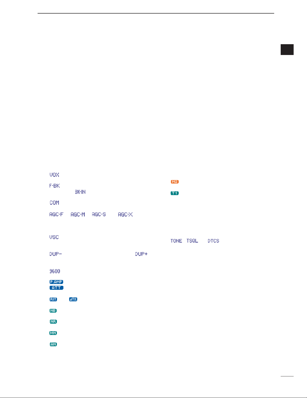
!6 FUNCTION INDICATORS
➥ “ ” appears when the VOX function is acti-
vated.
➥ “ ” appears when full break-in operation is se-
lected and “ ” appears when semi break-in
operation is selected.
➥ “ ” appears when the speech compressor is
activated.
➥ “ ,” “ ,” “ ” or “ ” (OFF)
appears when the fast time constant, middle time
constant, slow time constant or AGC OFF is selected, respectively.
➥ “”appears when the VSC (Voice Squelch
Control) function is activated in phone (SSB, AM,
FM, WFM) modes.
➥ “ ” appears for negative offset and “ ”
appears for positive offset during duplex operation.
➥ “”appears when the 9600 mode is activated
for packet operation.
➥ “ ” appears when the preamp is ON,
“”appears when the 12 dB attenuator is
ON.
➥ “ ” or “ ” appears when the RIT or ∂TX
function is activated.
➥ “ ” appears when the noise blanker is acti-
vated.
➥ “”appears when DSP noise reduction is acti-
vated.
➥ “” appears when the manual notch function is
activated.
➥ “”appears when the automatic notch function
is activated.
!7 MULTI-FUNCTION SCREEN
Shows the screens for the multi-function meter, simple band scope, SWR meter, memory channel,
voice recorder, memory keyer, DTMF memory encoder, RTTY decoder, IF filter selection or popup indication, etc.
!8 PRIORITY WATCH INDICATOR
Appears while priority scan is activated.
!9 SELECT MEMORY CHANNEL INDICATOR
Appears when select scan is enabled for the selected memory channel.
@0 1/4 FUNCTION INDICATOR
Appears when the
1
⁄4-speed tuning function is acti-
vated in CW and RTTY modes.
@1 EXTERNAL KEYPAD INDICATOR
Shows the memory keyer or voice memory channel
number. This indication appears when “
External
Keypad (VOICE)
” or “
External Keypad
(KEYER)
” in the miscellaneous (others) set mode
(p. 137) is set to ON, and which one is activated.
<Example>
• “”appears when the memory keyer “M2” is trans-
mitted.
• “”appears when the voice memory “T1” is transmit-
ted.
@2 CLOCK READOUT
Shows the current time.
•UTC time or local time can be selected.
@3 TONE INDICATOR
Appears during FM tone operation.
• “ ,” “ ” or “ ” appears when the repeater
tone, tone squelch, DTCS squelch are activated, respectively.
@4 TUNER INDICATOR
Appears when the optional automatic antenna tuner
is activated.
•This indicator blinks while the tuner is tuning..
Page 24
2
15
INSTALLATION AND CONNECTIONS
■ Unpacking
After unpacking, immediately report any damage to the
delivering carrier or dealer. Keep the shipping cartons.
For a description and a diagram of accessory equipment included with the IC-7000, see ‘Supplied accessories’ on p. i-1 of this manual.
■ Selecting a location
Select a location for the transceiver that allows adequate air circulation, free from extreme heat, cold, or
vibrations, and away from TV sets, TV antenna elements, radios and other electromagnetic sources.
The base of the transceiver has an adjustable stand
for desktop use. Set the stand to one of two angles depending on your operating conditions. (see description
on right hand page)
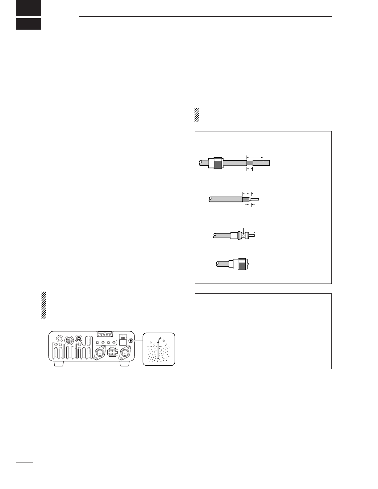
■ Grounding
To prevent electrical shock, television interference
(TVI), broadcast interference (BCI) and other problems, ground the transceiver through the GROUND
terminal on the rear panel.
For best results, connect a heavy gauge wire or strap
to a long, buried copper rod. Make the distance between the [GND] terminal and ground as short as possible.
R WARNING: NEVER connect the [GND] ter-
minal to a gas pipe or electric conduit, since the
connection could cause an explosion or electric
shock.
■ Antenna connection
For radio communications the antenna is of critical importance for output power and sensitivity. Use wellmatched 50-ohm antennas and coaxial feedline. An
SWR (standing wave radio) of 1.5:1 or lower is recommended when transmitting.
CAUTION: Protect your transceiver from lightning
by using a lightning arrestor.
ANTENNA SWR
Each antenna is tuned for a specified frequency
range and SWR increases outside that range. When
the SWR is higher than approx. 2.0 : 1, the transceiver’s power drops to protect the final transistors.
In this case, an antenna tuner is used to match the
transceiver and antenna. Low SWR allows full power
for transmitting even when using the antenna tuner.
The IC-7000 has an SWR meter to monitor the antenna SWR continuously.
PL-259 CONNECTOR INSTALLATION EXAMPLE
q
Coupling ring
w
e
r
30 mm
10 mm (soft solder)
10 mm
Soft
solder
1–2 mm
solder solder
Slide the coupling ring
down. Strip the cable
jacket and soft solder.
Strip the cable as
shown at left. Soft
solder the center conductor.
Slide the connector
body on and solder it.
Screw the coupling
ring onto the connector
body.
Page 25

2
2
16
INSTALLATION AND CONNECTIONS
■ Installation
D Single body mounting D Stand
*CAUTION: Non-supplied screws (longer than 8 mm)
may damage the internal units.
MB-62
(optional)
Supplied with
the MB-62*
Nut
Spring washer
Flat washer
D Front panel separation
D Front panel mounting
q While pulling the front panel latch towards you,
slide the front panel to the left (fig. 1).
w Attach the optional OPC-1443 to the main body
and tighten the supplied screw as in fig. 2.
e Attach the other end of the OPC-1443 to the de-
tached front panel as in fig. 3.
CAUTION: NEVER detach/attach the front panel
when connecting the DC power supply (or battery).
Be sure to disconnect the DC power cable from the
[13.8 V] socket on the transceiver rear panel.
q Attach the MB-105 to a flat surface using the four
supplied screws (fig. 1).
w Fix the detached front panel to the MB-105 as il-
lustrated in fig. 2.
BE CAREFUL to mount the MB-105 so that the
front panel attaches with the correct side up.
To raise the stand:
With the transceiver upside down, pull the stand towards the rear panel and then upwards, as illustrated below.
fig. 1
fig. 2 fig. 3
then up
Pull back
Latch
To remove
Separation cable
(OPC-1443)
Separation cable
(OPC-1443)
fig. 1
fig. 2
Page 26
17
2
INSTALLATION AND CONNECTIONS
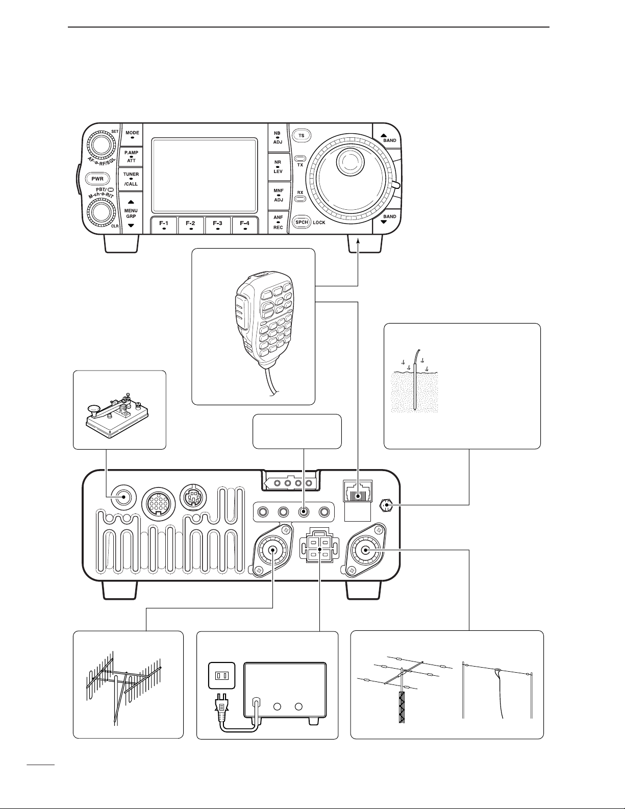
■ Required connections
KEY ACC DATA
MIC
ANT2 ANT1
DC 13.8V
GND
MICROPHONE (p. 10)
HF/50 MHz ANTENNA
GROUND (p. 15)
HM-151
RTTY TERMINAL
UNIT (p. 23)
Use the heaviest
gauge wire or strap
available and make
the connection as
short as possible.
Grounding prevents
electrical shocks, TVI
and other problems.
2 m/70 cm ANTENNA
STRAIGHT KEY
DC POWER SUPPLY (p.19)
A DC power supplyAC outlet
13.8 V; at least 25 A
Black
_
Red
+
Page 27
18
2
INSTALLATION AND CONNECTIONS
2
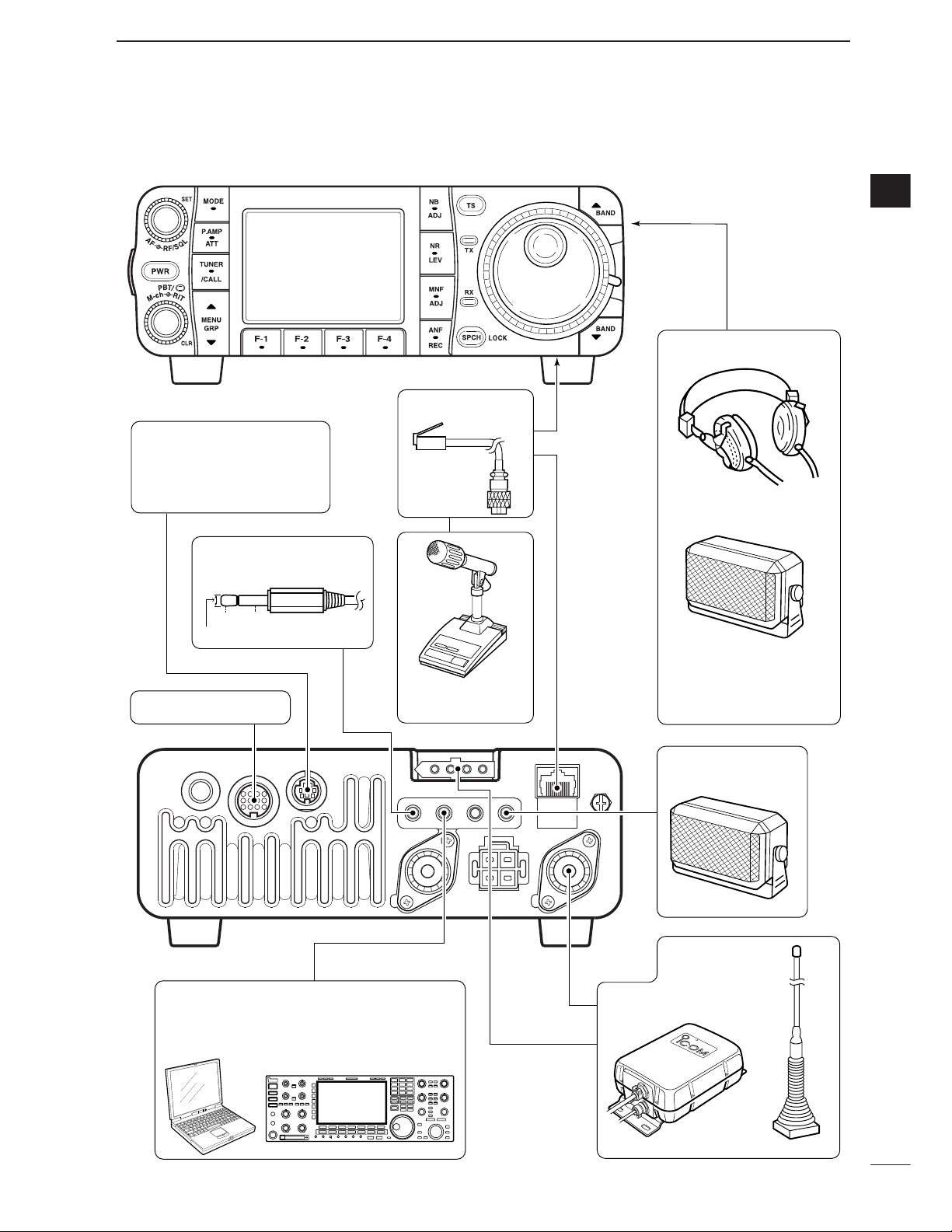
■ Advanced connections
KEY ACC DATA
MIC
ANT2 ANT1
DC 13.8V
GND
OPC-589 (p. 152)
DESKTOP (p. 151)
MICROPHONE
SPEAKER
ACC SOCKET (p. 12)
DATA SOCKET (p. 12)
VIDEO OUT
AH-4 (p. 20)
AH-2b
EXTERNAL
SPEAKER (p. 151)
HEADPHONES
SP-7/SP-10
SM-20
or
REMOTE (p. 144)
Used for computer control and transceive
operation.
Selectable with the
[PHONE/SPEAKER]
switch on the back of
the front panel.
6-pin mini DIN socket to
connect to a TNC, etc. for
packet operation.
to [VOUT] jack
3.5(d) mm
GND
Vout
Page 28
19
2
INSTALLATION AND CONNECTIONS
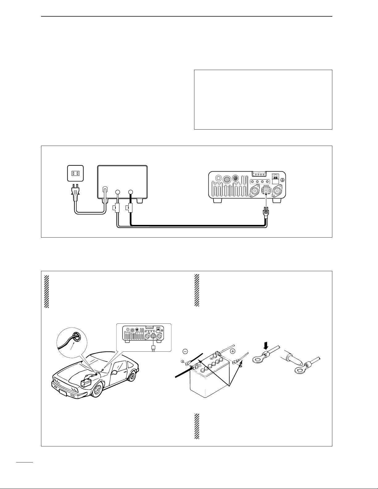
■ Power supply connections
Use the DC power supply with a 25 A capacity when
operating the transceiver with AC power. Refer to the
diagrams below.
CAUTION: Before connecting the DC power
cable, check the following important items. Make
sure:
•The [POWER] switch is OFF.
•Output voltage of the power source is 12–15 V.
• DC power cable polarity is correct.
Red : positive + terminal
Black : negative _ terminal
A DC power supplyAC outlet
AC cable
30 A fuses
Supplied
DC power cable
13.8 V; at least 25 A
Black
_
Red
+
Transceiver
DC power
socket
■ Battery connections
•RWARNING NEVER connect to a battery
without supplying a DC fuse, otherwise a fire
hazard occurs.
•NEVER connect the transceiver directly to a 24V
battery.
•DO NOT use the cigarette lighter socket for power
connections. (See p. 11 for details)
•Attach a rubber grommet when passing the DC
power cable through a metal plate to prevent a
short circuit.
IMPORTANT!
Detailed installation notes for Icom mobile transceivers to be fitted into vehicles are available. Contact your Icom dealer or distributor.
■ Connecting a DC power supply
CONNECTING A VEHICLE BATTERY
Grommet
Note:
Use terminals for
the cable connections.
Crimp
black
12 V
battery
red
Supplied
DC power cable
Solder
Page 29
20
2
INSTALLATION AND CONNECTIONS
2
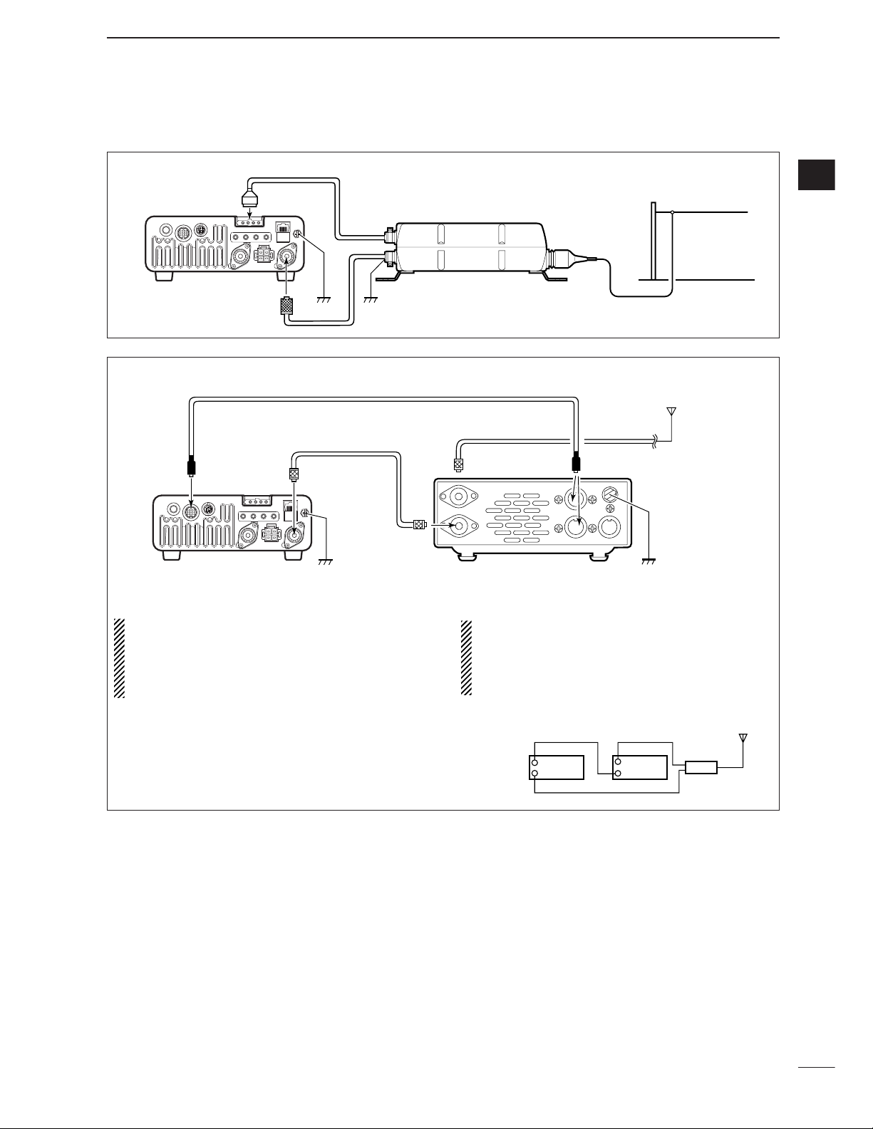
■ External antenna tuners
GroundGround
Long wire or optional AH-2b
AH-4
ANT1
IC-7000
Coaxial cable
(from the AH-4)
CONNECTING THE AH-4
CONNECTING THE AT-180
•Turn the IC-7000’s power OFF when connecting
the AT-180, otherwise, the CPU may malfunction
and the AT-180 may not function properly.
•The OPC-742 is required when using both the AT-
180 and a 2m/70cm linear amplifier.
• Do not connect [ANT2] to the AT-180. When using
an HF to 2m/70cm dual or wide-band antenna,
use a duplexer between the AT-180 and antenna
since 2 m/70 cm signals do not pass through the
AT-180.
[ANT 1]
Transceiver
Duplexer
HF to 2 m/70 cm
antenna
AT-180
[ANT 2]
ACC cable supplied with the AT-180
Coaxial cable supplied
with the AT-180
IC-7000
[ANT][ANT1][ACC] [ACC]
AT-180
HF
to 6 m
antenna
Either of the two
external connectors
Ground
[TRANSCEIVER]
Ground
Page 30
21
2
INSTALLATION AND CONNECTIONS
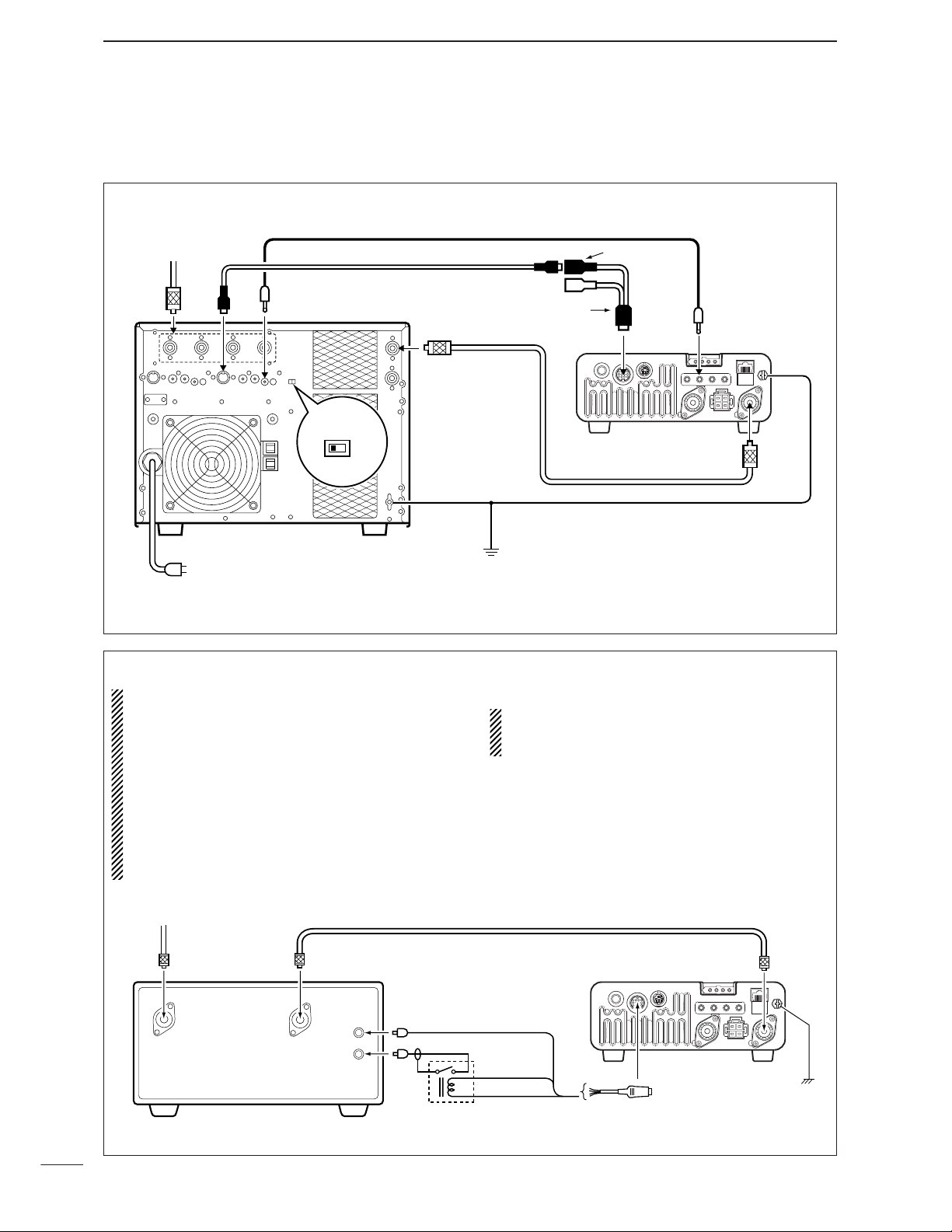
■ Linear amplifier connections
Use the [ANT1] connector when connecting an HF/50
MHz linear amplifier.
CONNECTING THE IC-PW1/EURO
To an
antenna
ACC-1
ANT
ANT1
ACC
INPUT1
REMOTE
EXCITER
1
1&2
GND
GND
IC-PW1/EURO
AC outlet
Non-European versions : 100–120/220–240 V
European version : 230 V
Ground
Transceiver
REMOTE
Remote control cable (supplied with the IC-PW1/EURO)
ACC cable (supplied with the IC-PW1/EURO)
Coaxial cable
(supplied with the IC-PW1/EURO)
7-pin side
OPC-599 conversion cable
()
CONNECTING A NON-ICOM LINEAR AMPLIFIER
R WARNING:
•Set the transceiver output power and linear ampli-
fier ALC output level referring to the linear amplifier instruction manual. Be sure the linear amplifier keying circuit control voltage is compatible
with the IC-7000, before connecting to HSEND
line (ACC cable).
•The ALC input level must be in the range 0 V to
–4 V, and the transceiver does not accept positive
voltage. Non-matched ALC and RF power settings
could cause a fire or damage the linear amplifier.
•The IC-7000 SEND relay is rated at 16 V and a
0.5 A DC. If these levels are exceeded, a larger
external relay must be used.
To an
antenna
RF INRF OUT
50 1 coaxial cable
ALC
KEY
Relay
ALC (Blue)
HSEND
(Orange)
13.8V (Gray)
Transceiver
ACC cable
ACC
ANT1
Ground
GND
Page 31

22
2
INSTALLATION AND CONNECTIONS
2
Rear panel
Paddle
[KEY]
[MICROPHONE]
Straight key
Microphone (HM-103)
Keyer set mode setting
Keyer set mode (p. 49)
4
8
12
[ACC]
123
765
9
10 11
13
For no break-in operation:
Connect an external switch
such as a foot switch; or use
the RTTY SEND terminal for
all bands. (See p. 23)
See p. 50 for connection details:
Paddle operation from [MIC]
connector
.
Normal
Reverse
Bug
Paddle polarity
Normal
MIC U/D keyer (HM-103)
ON
Keyer Type
ELEC-KEY
Paddle polarity
Normal
Keyer Type
Straight
Paddle polarity
Normal
Keyer Type
ELEC-KEY
Paddle polarity
Reverse
Keyer Type
ELEC-KEY
Paddle polarity
Normal
Keyer Type
BUG-KEY
■ Connections for CW
Page 32
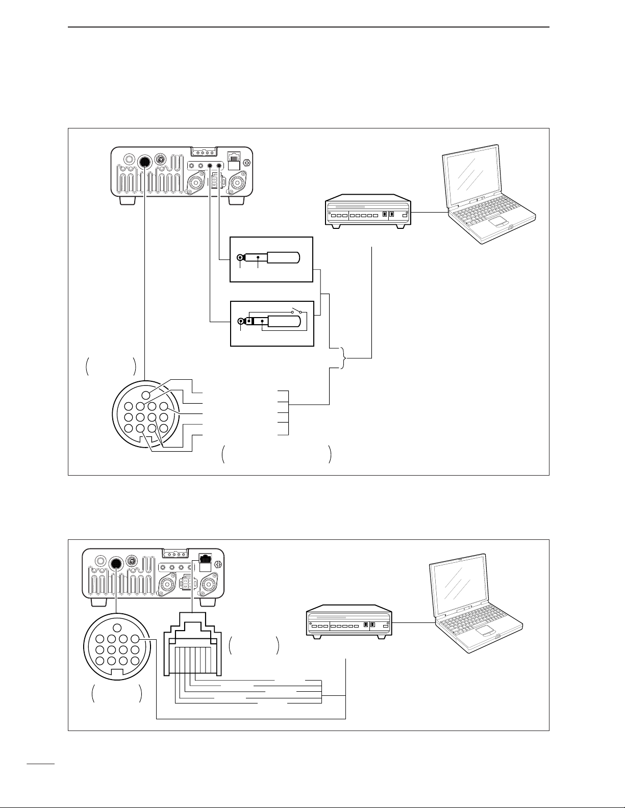
23
2
INSTALLATION AND CONNECTIONS
[ACC]
Rear panel
4
8
12
123
765
9
10 11
13
[RTTY] [EXT SP]
TU or TNC
Personal computer
Rear panel
view
Colors refer to connection
to the supplied ACC cable.
*
1
Connect SQL line when required.
eHF/50 MHz: orange
u144/430 MHz: purple
*
2
SQL*1 (light green)
FSKK (black)
AF out (light blue)
MSEND*
2
GND (red)
GND
GND
AF
3-conductor
1
/8˝ plug (supplied)
2-conductor
1
/8˝ plug
FSKK
SEND
D When connecting to [ACC] socket
D When connecting to [MIC] connector
[MIC][ACC]
Rear panel
i SQL
!2 AF out (light blue)
r
PTT
t
GND
y
MIC
u
GND
Rear panel
view
TU or TNC
Personal computer
4
8
12
123
765
9
10 11
13
Rear panel
view
■ Connections for RTTY (FSK)
Page 33

24
2
INSTALLATION AND CONNECTIONS
2
■ Connections for packet
D When connecting to [DATA] socket
D When connecting to [MIC] connector
D When connecting to [ACC] socket
[MIC][ACC]
Rear panel
i SQL
!2 AF out (light blue)
r
PTT
t
GND
y
MIC
u
GND
Rear panel
view
TU or TNC
Personal computer
4
8
12
123
765
9
10 11
13
Rear panel
view
DATA IN
PTTP
[DATA] (Rear panel)
qw
e
AF OUT
GND
r
DATA OUT
yt
SQL
Rear panel
TX AUDIO
GND
RX AUDIO
SQL
PTT
RS-232C
TU or TNC
Personal computer
[ACC]
Rear panel
view
13
10 11
9
765
123
12
8
4
SQL*1 (light green)
AF in (pink)
AF out (light blue)
MSEND (orange)
GND (red)
TU or TNC
1
*
Connect SQL line when required.
Colors refer to connection
to the supplied ACC cable.
Personal computer
Page 34

3
25
BASIC OPERATION
■ When first applying power (CPU resetting)
Before first applying power, make sure all connections required for your system are complete by referring to Chapter 2. Then, reset the transceiver using
the following procedure.
Resetting CLEARS all programmed contents in
memory channels and returns programmed values
in set mode.
q Make sure the transceiver power is OFF.
w While pushing [Y(
BAND
)] and [Z(
BAND
)], push
[PWR] for 1 sec. to start resetting.
• The internal CPU is reset.
•The display changes to ‘ALL CLEAR,’ ‘RF power 100%’
and ‘Initial frequency and Mode’ as shown at right.
The transceiver’s
initial frequency and mode
[PWR]
[Y]
[Z]
D Menu resetting (
M
-
1
)
Turn power ON, then check the display. If any of the
following indicators appear, turn them OFF as follows:
•Tuning step indicators,
Z
, (SSB, CW or RTTY):
Push [TS].
•MHz tuning step indicator,
Z
, (FM, WFM or AM):
Push [TS]
• 1 Hz frequency readout (SSB, CW or RTTY):
Push and hold [TS].
• Preamp indicator, :
Push [P.AMP/ATT]
• Attenuator indicator, :
Push [P.AMP/ATT]
• Noise blanker indicator, :
Push [NB/ADJ]
• Noise reduction indicator, :
Push [NR/LEV]
• Manual notch indicator, :
Push [MNF/ADJ]
• Auto notch indicator, :
Push [ANF/•REC]
• Memory mode indicator, MEMO:
Use [F-4
V/M
] in the
M
-
2
menu (p. 27).
• Split indicator, :
Use [F-1
SPL
] in the
M
-
1
menu (p. 91).
If you can’t figure out how to return to the menu
M
-
1
:
While pushing either [Y(
MENU/GRP
)] or [
Z
(
MENU/GRP
)], turn power ON.
•The other groups are also reset to
S
-
1orG-1
(Scope) in
this time.
[PWR]
[MENU/GRP]
After resetting the transceiver, set controls and
switches as shown in the diagram below.
■ Initial settings
[AF]: Max. CCW
[POWER]: OFF
[PBT]: Center
(Push and hold for 1 sec.)
CCW : counterclockwise
[RF/SQL]: Center
[PBT/M-ch/RIT]
(indicator lights)
[LOCK]: OFF
: PBT
Page 35

D Differences between VFO and memory mode
VFO MODE
Each VFO shows a frequency and operating mode. If
the frequency or operating mode is changed, the VFO
automatically memorizes the new frequency or operating mode.
When VFO settings are changed with frequency and
mode from another VFO or memory mode, the lastused frequency and operating mode for that VFO appear.
[EXAMPLE]
MEMORYMODE(pgs. 102–110)
Each memory channel shows a frequency and operating mode like a VFO. Even if the frequency or mode
is changed, the memory channel does not memorize
the new frequency or operating mode.
When a memory channel is changed with frquency
and mode from another memory channel or VFO
mode, the memorized frequency and operating mode
appear.
[EXAMPLE]
26
3
BASIC OPERATION
3
VFO is an abbreviation of Variable Frequency Oscillator, and traditionally refers to an oscillator.
The IC-7000 VFO is somewhat different. The VFO display of the IC-7000 acts like a computer’s window and
can show one frequency and one operating mode.
You can call up a desired frequency to the VFO with
the memo pad-read key (p. 112) or the memory transfer function (p. 109). You can also change the frequency with [DIAL] and select an operating mode with
[MODE] key or call up previously accessed frequency
and modes with the band stacking register (p. 28).
The IC-7000 has two VFOs, specially suited for split
frequency operation. The VFOs are called VFO A and
VFO B. You can use the desired VFO to call up a frequency and operating mode for operation.
VFO
MODE
KEY
Select
MEMORY
CHANNEL
DIAL
MEMO PAD
28.025 MHz
7.001 MHz
21.295 MHz
BAND
Change
Transfer
Transfer Transfer
Changed frequency (14.123 MHz) does not appear and
memorized frequency (14.100 MHz) appears instead.
Memory channel 1 is
selected.
The frequency is changed.
Memory channel 1 is
selected again.
Another memory channel
is selected.
VFO is selected.
The frequency is changed.
VFO is selected again.
Changed frequency (14.123 MHz) appears.
Memory mode is selected.
■ VFO description
Page 36

■ Selecting VFO/memory mode
27
3
BASIC OPERATION
q Select
M
-
1
.
w Push [F-2
A/B
] to toggle VFO A or VFO B.
[MENU/GRP] [F-2]
Either “ ” or “ ” appears.
D
Selecting VFO A/VFO B
q Select
M
-
1
.
w Push [F-2
A/B
] for 1 sec. to set the undisplayed
VFO frequency and mode to those of the displayed
VFO.
•Three beeps sound when the VFO equalization is com-
pleted.
CONVENIENT
Use two VFOs as a quick memory
When you find a new station, but you wish to continue
searching, the Two VFO system can be used for quick
memory storage.
q Push [F-2
A/B
] for 1 sec. to store the displayed fre-
quency into the undisplayed VFO.
w Continue searching for stations.
e Push [F-2
A/B
] to retrieve the stored frequency.
r To continue searching for a station, push [F-2
A/B
]
again.
Push
then push again.
for 1 sec.,
D
VFO equalization
■ VFO operation
q Select
M
-
2
.
w Push [F-4
V/M
] to toggle VFO and memory
modes.
“VFO” indicator
Memory channel
indicator
[MENU/GRP] [F-4]
Menu group selection
Push [MENU/GRP] for 1 sec.
Selection from:
M,SorG
(Graphic)
Menu selection (Example: M)
Push [MENU/GRP] momentarily.
Selection from:
M-1,M-2orM-3
Either
Either
Y or Z
Y or Z
Page 37
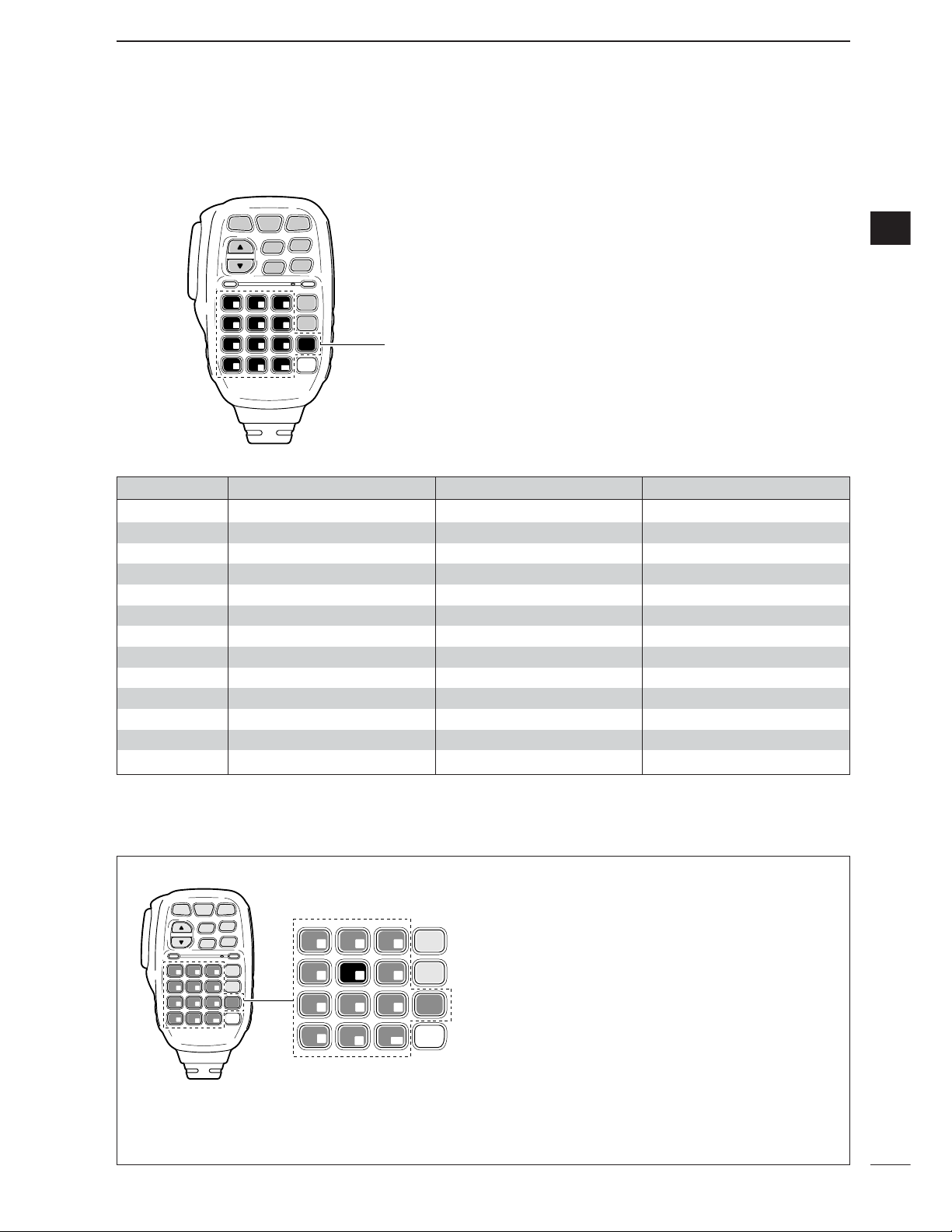
28
3
BASIC OPERATION
3
The triple band stacking register provides 3 memories
in one band. 3 sets of frequency and operating mode
on each band are automatically stored when used.
If a band key (on the HM-151) is pushed once, the last
used frequency and operating mode are called up.
When the key is pushed again, another stored frequency and operating mode are called up.
This function is convenient when you operate 3 operating modes on one band. For example, one register
is used for a CW frequency, another for an SSB frequency and the other one for an RTTY frequency.
See the table below for a list of the bands available
and the default settings for each band.
SPCH
/LOCK
TUNER
/CALL
XFC
V/M
F-1
F-2
FIL
MODE
GENE
MW
123
456
789
.
0
CE
F-INP
ENT
1.8 3.5 7
10 14 18
21 24 28
50 144 430
Band keys
HM-151
■ Selecting an operating band
BAND REGISTER 1 REGISTER 2 REGISTER 3
1.8 MHz 1.900000 MHz CW 1.910000 MHz CW 1.915000 MHz CW
3.5 MHz 3.550000 MHz LSB 3.560000 MHz LSB 3.580000 MHz LSB
7 MHz 7.050000 MHz LSB 7.060000 MHz LSB 7.020000 MHz CW
10 MHz 10.120000 MHz CW 10.130000 MHz CW 10.140000 MHz CW
14 MHz 14.100000 MHz USB 14.200000 MHz USB 14.050000 MHz CW
18 MHz 18.100000 MHz USB 18.130000 MHz USB 18.150000 MHz USB
21 MHz 21.200000 MHz USB 21.300000 MHz USB 21.050000 MHz CW
24 MHz 24.950000 MHz USB 24.980000 MHz USB 24.900000 MHz CW
28 MHz 28.500000 MHz USB 29.500000 MHz USB 28.100000 MHz CW
50 MHz 50.100000 MHz USB 50.200000 MHz USB 51.000000 MHz FM
144 MHz 145.000000 MHz FM 145.100000 MHz FM 145.200000 MHz FM
430 MHz 433.000000 MHz FM 433.100000 MHz FM 433.200000 MHz FM
General 15.000000 MHz USB 15.100000 MHz USB 15.200000 MHz USB
q Push [(14)5], then select a frequency and an oper-
ating mode.
•Frequency and operating mode are memorized in the
first band stacking register.
w Push [(14)5] again, then select another frequency
and operating mode.
•This frequency and operating mode are memorized in
the second band stacking register.
e Push [(14)5] again, then select another frequency
and operating mode.
•This frequency and operating mode are memorized in
the third band stacking register.
•When a fourth frequency and operating mode are selected on a band, the first register set in step q, is over
written.
SPCH
/LOCK
TUNER
/CALL
XFC
V/M
F-1
F-2
FIL
MODE
GENE
MW
123
456
789
.
0
CE
F-INP
ENT
1.8 3.5 7
10 14 18
21 24 28
50 144 430
FIL
MODE
GENE
123
4 5 6
789
.
0
CE
F-INP
ENT
1.8 3.5 7
10 14 18
21 24 28
50 144 430
[Example]: 14 MHz band
HM-151
D
Using the band stacking registers
Page 38
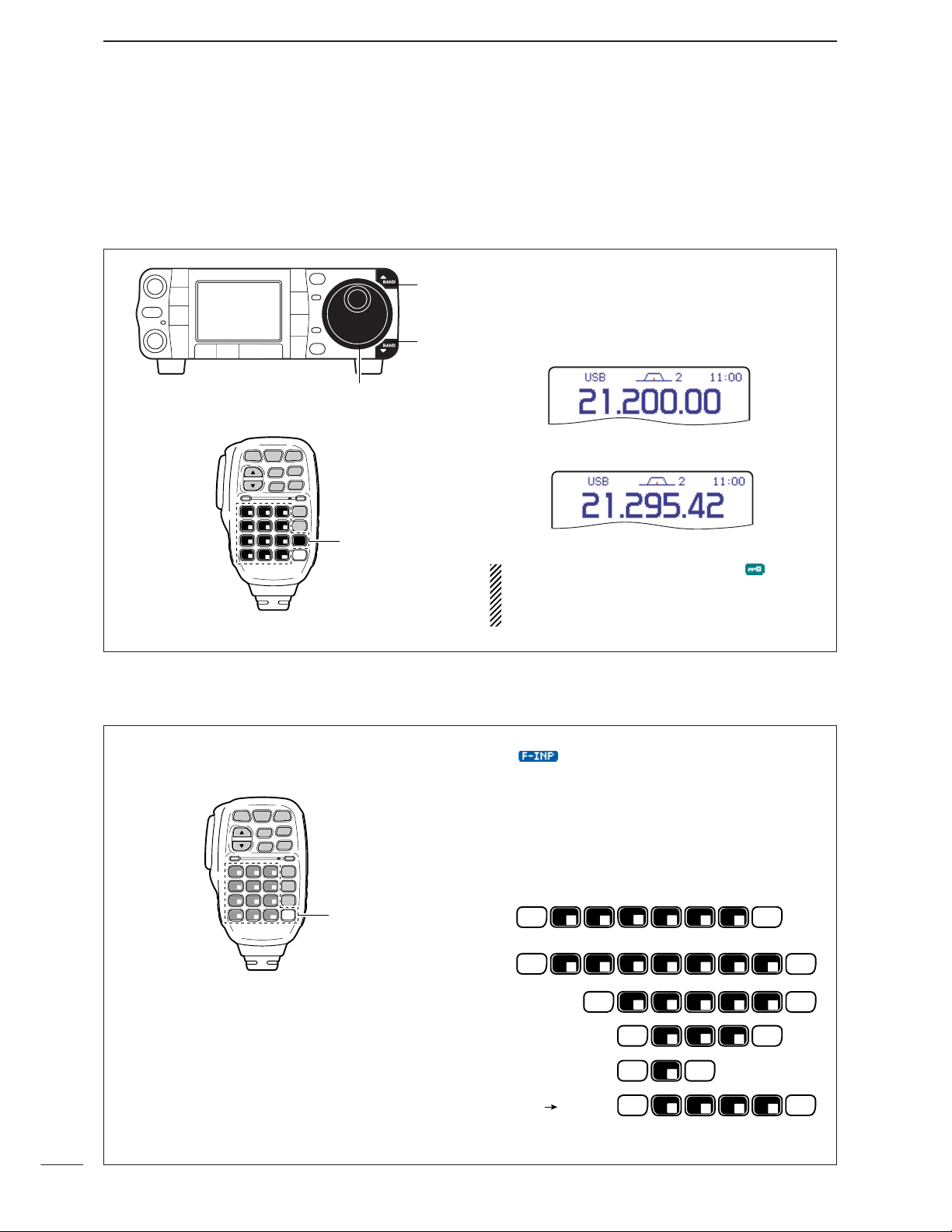
29
3
BASIC OPERATION
The transceiver has several tuning methods for convenient frequency tuning.
■ Frequency setting
D
Tuning with the main dial
q Push [Y(
BAND
)] or [Z(
BAND
)] to select the desired
band. Or push the desired band key on the micro-
phone 1–3 times.
•Three different frequencies can be selected on each
band with the microphone’s band key. (See previous
page “Using the band stacking register.”)
w Rotate [DIAL] to set the desired frequency.
If the dial lock function is activated, “ ” indicator
lights, and [DIAL] does not function. In this case,
push [SPCH/LOCK] to deactivate the lock function. (p. 37)
D
Direct frequency entry with the microphone’s keypad
The HM-151 has a keypad for direct frequency entry
as described right.
q Push [F-INP/ENT].
• “ ” appears.
w Input the desired frequency.
•Push [(50)•] to input “ • (decimal point)” between the
MHz digits and kHz digits.
e Push [F-INP/ENT] to set the input frequency.
•To cancel the input, push [CE] instead of [F-INP/ENT].
[EXAMPLES]
F-INP
ENT
F-INP
ENT
F-INP
ENT
F-INP
ENT
F-INP
ENT
F-INP
ENT
F-INP
ENT
F-INP
ENT
F-INP
ENT
F-INP
ENT
F-INP
ENT
1
1.8
1
1.8
1
1.8
2
3.5
2
3.5
2
3.5
4
10
4
10
5
14
5
14
5
14
F-INP
ENT
5
14
6
18
7
21
7
21
7
21
8
24
.
50
.
50
.
50
.
50
.
50
0
144
0
144
0
144
0
144
21.280 21.245
14.025 MHz
18.0725 MHz
706 kHz
5.100 MHz
7.000 MHz
[Y]
[Z]
[DIAL]
HM-151
SPCH
TUNER
/LOCK
/CALL
V/M
F-1
1.8 3.5 7
123
10 14 18
456
21 24 28
789
50 144 430
.
0
XFC
MW
F-2
MODE
FIL
GENE
F-INP
ENT
CE
Band keys
HM-151
SPCH
TUNER
XFC
/LOCK
/CALL
MW
V/M
F-2
F-1
1.8 3.5 7
10 14 18
21 24 28
50 144 430
123
456
789
.
CE
0
MODE
FIL
GENE
F-INP
ENT
Keypad
Page 39

30
3
BASIC OPERATION
3
D
Programmable tuning step
The operating frequency can be changed in steps of
(0.01 (AM/FM/WFM only), 0.1, 1, 5, 9, 10, 12.5, 20 25
or 100 kHz selectable) for quick tuning.
q Push [TS] momentarily to turn the programmable
tuning function ON.
•“Z” appears when the programmable tuning function is
ON.
w Rotate [DIAL] to change the frequency in pro-
grammed kHz steps.
e Push [TS] again to turn the programmable tuning
function OFF.
•“Z” disappears.
r Rotate [DIAL] for normal tuning, if desired.
Programmable tuning step indicator
[TS] [DIAL]
Appears
D
Selecting “kHz” step
Programmable tuning steps are available to suit your
operating requirements.
These tuning steps are:
• Independently selectable for each mode
•Selectable from 0.01 (AM/FM/WFM only), 0.1, 1, 5,
9, 10, 12.5, 20, 25 and 100 kHz
q Push [TS] momentarily to turn the programmable
tuning step ON.
•“Z” appears when the programmable tuning function is
ON.
w Push [TS] for 1 sec. to enter the tuning step set-
ting display.
•The tuning step setting for the selected mode appears.
e Select the desired operating mode with [MODE].
(see p. 34)
r Rotate [DIAL] to select the desired tuning step
from 0.01 (FM/WFM/AM only), 0.1, 1, 5, 9, 10,
12.5, 20, 25 or 100 kHz.
•Push [F-4
DEF
] for 1 sec. to return to the default set-
ting, if desired.
t Repeat steps e and r to select the “kHz” tuning
steps for other modes, if desired.
y Push [TS] (or [Z(
MENU/GRP
)]) to exit the setting
display.
Appears
[TS][MODE] [DIAL]
Page 40

31
3
BASIC OPERATION
When neither the quick tuning step or programmable
tuning step “
Z
” appear, rotating [DIAL] changes the
frequency in increments of 1 or 10 Hz. These tuning
steps are only available in SSB, CW and RTTY
modes.
q Select SSB, CW or RTTY mode if necessary.
w Push and hold [TS] for 1 sec. to toggle between
the 1 Hz and 10 Hz step settings.
•When the 1 Hz step is selected, the 1 Hz digit appears
in the frequency indication; when the 10 Hz step is selected, the 1 Hz digit disappears from the frequency indication.
•Rotating [DIAL] changes the frequency in 1 Hz or 10Hz
tuning step.
Push and hold
for 1 sec.
Rotating [DIAL] changes the
frequency in 1 Hz steps.
Rotating [DIAL] changes the
frequency in 10 Hz steps.
[TS][MODE] [DIAL]
D
Selecting 1 Hz or 10 Hz step (SSB/CW/RTTY only)
The quick tuning step function allows you to change
the frequency in 1 MHz steps when rotating [DIAL].
This function is only available in FM, WFM and AM
modes.
q Select FM, WFM or AM mode if necessary.
w Push [TS] momentarily to toggle between the 1
MHz tuning step and the programmable tuning
step.
•“Z” appears above the 1 MHz indicator when the 1
MHz tuning step is selected.
•Rotating [DIAL] changes the frequency 1 MHz.
Quick tuning step indicator
Rotating [DIAL]
changes the frequency
in 1 MHz steps.
[TS][MODE] [DIAL]
Appears
D
1 MHz quick tuning step (FM/WFM/AM only)
Page 41

32
3
BASIC OPERATION
3
• [TS] switch flow chart
SSB/CW/RTTY modes Any mode FM/WFM/AM modes
1 Hz tuning
10 Hz tuning
momentarily momentarily
1 MHz tuning
Programmable step tuning
(100 Hz –100 kHz)
momentarily
PushPush
Push Push
1 sec.1 sec.
1 sec.
Selectable for each mode.
Appears Appears
Appears
D
1
⁄
4 tuning function (CW/RTTY only)
While operating in CW/RTTY, the 1⁄4 tuning function is
available for critical tuning. Dial sensitivity is reduced
to
1
⁄4 of normal when the 1⁄4 function is in use.
q Select
M
-
3
.
w Push [F-2
1/4
] to toggle the
1
⁄4 function ON and
OFF.
• “ ” indication appears when the function is in
use.
[MENU/GRP] [F-2]
Appears
•Push and hold [MENU/GRP] for 1 sec. once or twice
to select the menu group M.
•Push [MENU/GRP] momentarily one or more times to
select the menu
M
-
3
.
Page 42

33
3
BASIC OPERATION
■ Volume setting
Rotate [AF] control clockwise to increase; counterclockwise to decrease the audio output level.
• Set a suitable audio level.
[AF]
Audio outut
decreases
Audio output
increases
D Band edge warning beep
When selecting a frequency that lies outside of a
band’s specified frequency range, a warning beep
sounds.
This function can be turned OFF in set mode, if desired.
q Enter the miscellaneous (others) set mode as
above.
w Push [F-1≤] or [F-2≥] to select “
Beep (Band
Edge)
,” then rotate [DIAL] to select the desired
setting.
•Push[F-4
DEF
] for 1 sec. to return to default setting.
e Push [Z(
MENU/GRP
)] twice to return the normal op-
erating mode.
D
Auto tuning step function
When rotating the tuning dial rapidly, the tuning speed
accelerates automatically as selected.
q Push [AF(
SET
)] momentarily to enter the set mode
menu.
w Push [F-4
OTH
] to enter the miscellaneous (oth-
ers) set mode.
e Push [F-1≤] or [F-2≥] to select “
MAIN DIAL
Auto TS
.”
r Rotate [DIAL] to select the desired tuning speed
from high, low and OFF.
•HIGH: Approx. 5 times faster
•LOW : Approx. twice faster
•OFF : Auto tuning step is turned OFF
•Push[F-4
DEF
] for 1 sec. to return to default setting.
t Push [Z(
MENU
/
GRP
)] twice to return to the normal
operating mode.
[DIAL][MENU/GRP]
[AF]
[F-1] [F-2] [F-4]
Page 43

34
3
BASIC OPERATION
3
■ Operating mode selection
The following modes are available in the IC-7000:
SSB (LSB/USB), CW, CW-R (CW reverse), RTTY,
RTTY-R (RTTY reverse), AM, FM and WFM (receive
only).
To select the desired mode of operation, push
[MODE] one or more times, then push [MODE] for
1 sec., if necessary. See the diagram at right for the
order of selection.
• The selected mode is indicated in the function display.
NOTE:
If a desired mode cannot be selected, it
may be hidden because of a setting in the miscellaneous (others) set mode (p. 136).
SPCH
/LOCK
TUNER
/CALL
XFC
V/M
F-1
F-2
FIL
MODE
GENE
MW
123
456
789
.
0
CE
F-INP
ENT
1.8 3.5 7
10 14 18
21 24 28
50 144 430
HM-151
MODE
OPERATING MODE SELECTION
Push
momentarily
Push and hold
for 1 sec.
USB LSB
AM FM WFM
CW CW-R
RTTY-R
RTTY
■ Voice synthesizer function
The IC-7000 has a voice synthesizer function. This
function announces the S-meter level, operating frequency and mode (S-meter level’s announcement
can be deactivated—p. 134) in a clear, electronically
generated voice, in English (or Japanese).
q Select the desired parameters to be announced,
such as Audio level, speed, language, contents, in
the miscellaneous (others) set mode. (p. 134)
w Push [SPCH/LOCK] momentarily to announce the
selected contents.
•Push [SPCH/LOCK] momentarily to stop the announcement.
[SPCH/LOCK]
[MODE]
Page 44

35
3
BASIC OPERATION
■ Squelch and receive (RF) sensitivity
Adjusts the RF gain and squelch threshold level. The
squelch removes noise output from the speaker
(closed position) when no signal is received.
• The squelch is particularly effective for FM. It is also available for other modes.
•The 12 to 1 o’clock position is recommended for any setting of the [RF/SQL] control.
•The control can be set as ‘Auto’ (RF gain control in SSB,
CW and RTTY; squelch control in AM, FM and WFM (RF
gain is fixed at maximum) in the miscellaneous (others)
set mode as follows (p. 131).
Adjusting RF gain (Receive sensitivity)
Normally, [RF/SQL] is set to the 11 o’clock position.
Rotate [RF/SQL] to the 11 o’clock position for maximum sensitivity.
• Rotating counterclockwise from the maximum position reduces sensitivity.
• The S-meter indicates receive sensitivity.
Adjusting squelch (Removing non-signal noise)
Rotate [RF/SQL] clockwise when receiving no signal,
until the noise just disappears.
• [RX] indicator light goes out.
• Rotating [RF/SQL] past the threshold point invokes the S-
meter squelch—this allows you to set a minimum signal
level needed to open the squelch.
• When setting as RF gain/squelch control
•When functioning as RF gain control
(Squelch is fixed open; SSB, CW, RTTY only)
•When functioning as squelch control (RF gain is
fixed at maximum)
While rotating the RF gain control, noise may be
heard. This comes from the DSP unit and does not
indicate an equipment malfunction.
SETTING OPERATION
RF+SQL
Can be used in all modes.
(default)
Functions as noise squelch or S-meter
squelch in AM, FM and WFM modes;
S-meter squelch only in other modes.
SQL
Operates as a squelch control.
• RF gain is fixed at maximum sensitivity.
Operates as an RF gain control in
SSB, CW and RTTY modes.
AUTO
• Squelch is fixed open.
Operates as a squelch control in AM,
FM and WFM modes.
• RF gain is fixed at maximum sensitivity.
[RF/SQL]
Noise squelch (FM/WFM mode)
Squelch is
open.
RF gain
adjustable
range
Recommended level
Maximum
RF gain
S-meter shows
squelch level
Adjustable
range
Minimum RF gain
Maximum RF gain
Noise squelch
threshold
(FM/WFM mode)
Squelch is
open.
Lowest threshold Highest threshold
Noise squelch (FM/WFM mode)
S-meter squelch
threshold
S-meter
squelch
Page 45
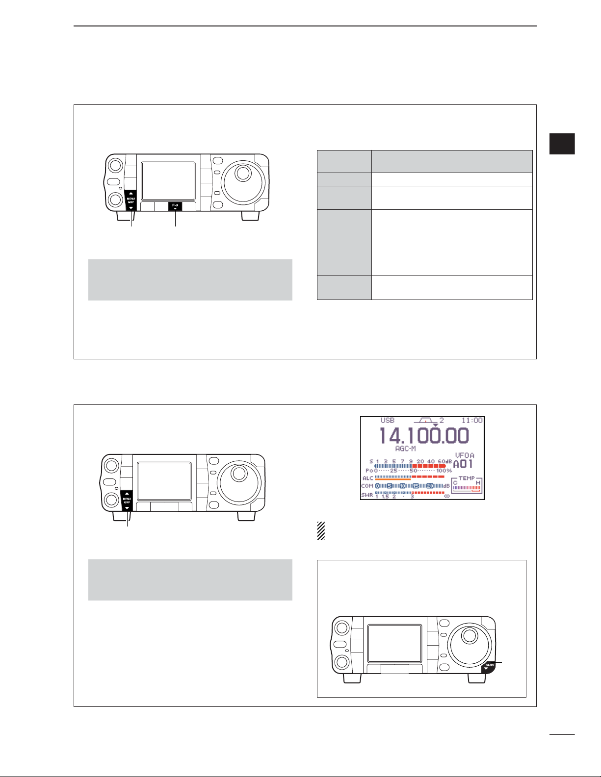
D Multi-function meter
36
3
BASIC OPERATION
3
■ Meter function
The transceiver has 4 transmit meter functions for
your convenience. Select the desired meter with the
[F-3
MET
] in the
S
-
1
display.
q Select
S
-
1
.
w Push [F-3
MET
] one or more times to select from
RF power
(Po), SWR, ALC or compression level
(COM).
•The display indication changes as the table at the right.
•Push and hold [MENU/GRP] for 1 sec. once or twice
to select the menu group S.
•Push [MENU/GRP] momentarily one or more times to
select the menu
S
-
1
.
[MENU/GRP] [F-3]
DISPLAY
MEASUREMENT
INDICATION
Po
Indicates the relative RF output power in %.
SWR
Indicates the SWR on the transmission
line.
ALC
Indicates the ALC level. When the meter
movement shows the input signal level exceeds the allowable level, the ALC limits
the RF power. In such cases, reduce the
MIC gain setting (see p. 38) in the quick
set mode.
COM
Indicates the compression level when the
speech compressor is in use.
In addition, the transceiver can display the multi-function meter in the graphic display, which displays all
transmit meters simultaneously.
➥ Select
G
-
2
(Multi-meter).
The multi-function meter displays the internal tem-
perature meter for your reference.
•Push and hold [MENU/GRP] for 1 sec. once or twice
to select the menu group G.
•Push [MENU/GRP] momentarily one or more times to
select the menu
G
-
2
(Multi-meter).
[MENU/GRP]
Quick entry
➥ Push [Z(
BAND
)] for 1 sec. to turn the multi-
function meter ON and OFF.
•Push [Z(
MENU/GRP
)] also to turn OFF.
[Z]
Page 46
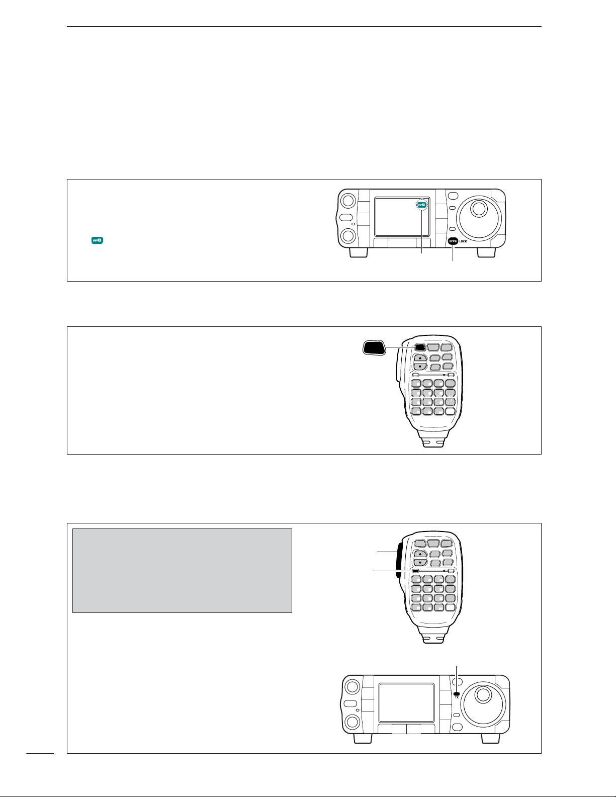
■ Basic transmit operation
D Transmitting
37
3
BASIC OPERATION
q Push [PTT] (microphone) to transmit.
• [TX] indicator lights red.
w Release [PTT] (microphone) to return to receive.
[TX] indicator
SPCH
/LOCK
TUNER
/CALL
XFC
V/M
F-1
F-2
FIL
MODE
GENE
MW
123
456
789
.
0
CE
F-INP
ENT
1.8 3.5 7
10 14 18
21 24 28
50 144 430
[PTT]
[TX]
HM-151
Before transmitting, monitor your selected operating frequency to make sure transmitting
won’t cause interference to other stations on
the same frequency. It’s good Amateur practice
to listen first, and then, even if nothing is heard,
ask “is the frequency in use” once or twice, before you begin operating on that frequency.
D Microphone lock function
This function locks microphone keypads.
➥ Push [SPCH/LOCK] (microphone) for 1 sec. to
toggle the microphone lock function ON and OFF.
• “MIC LOCK ON” and “MIC LOCK OFF,” popup indicators appear, respectively
• [PTT] and [SPCH/LOCK] can be used.
• All keys on the transceiver can be used.
SPCH
/LOCK
TUNER
/CALL
XFC
V/M
F-1
F-2
FIL
MODE
GENE
MW
123
456
789
.
0
CE
F-INP
ENT
1.8 3.5 7
10 14 18
21 24 28
50 144 430
HM-151
SPCH
/LOCK
■ Lock functions
The dial lock function prevents accidental change
caused by [DIAL].
➥ Push [SPCH/LOCK] for 1 sec. to turn the dial lock
function ON and OFF.
•“ ” indicator appears while the dial lock function is
activated.
[SPCH/LOCK]
Appears
D Dial lock function
The lock function can only be activated when displaying frequency, not in set mode, memory channel listing, or TV display.
Page 47
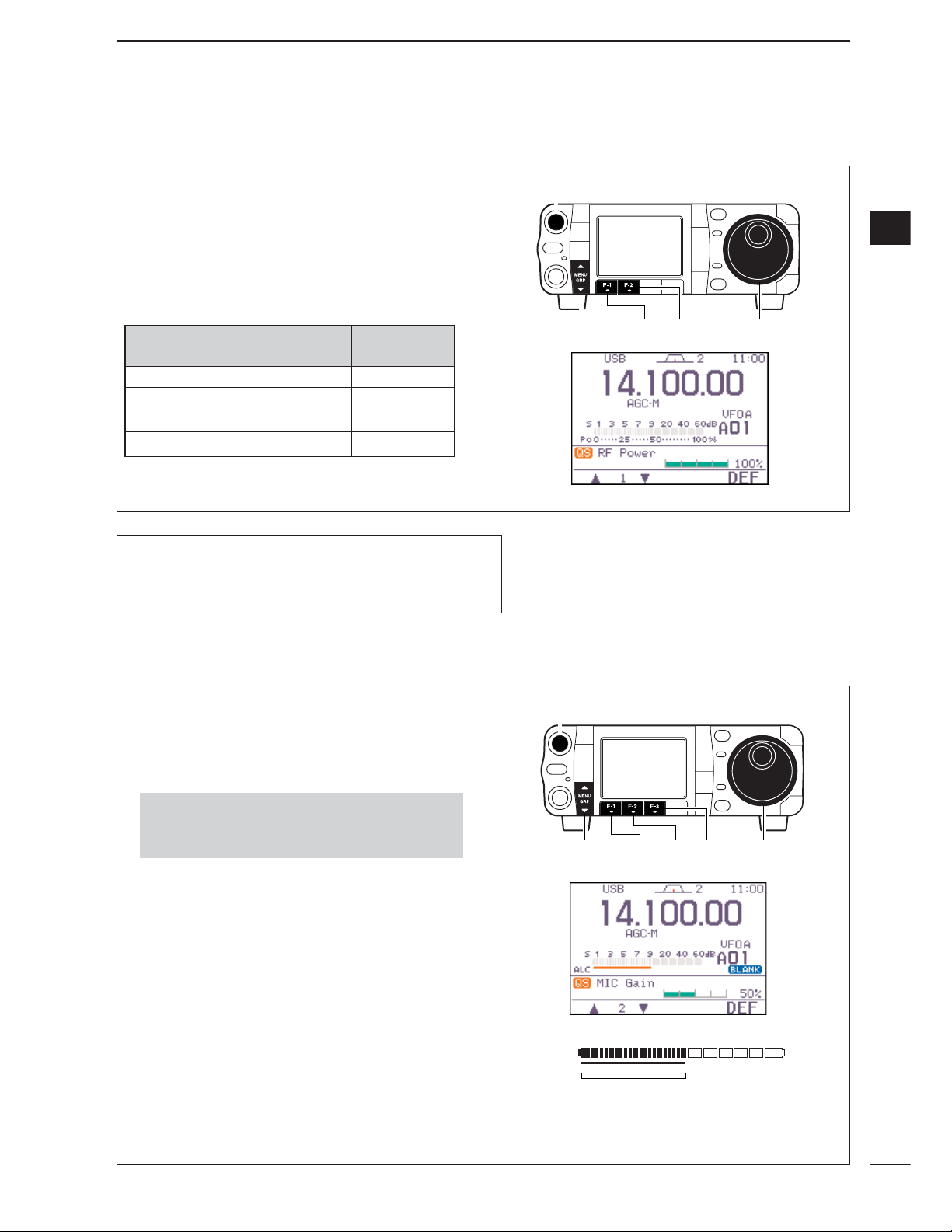
38
3
BASIC OPERATION
3
q Push [AF(
SET
)] momentarily to enter the set mode
menu.
w Push [F-1QS] to enter the quick set mode.
e Push [F-1 Y] or [F-2 Z] to select “
RF Power
.”
r Rotate [DIAL] to set the desired output setting.
•Output power is displayed in 1% steps (0% to 100%).
t Push [Z(
MENU/GRP
)] to exit quick set mode.
• Available power
*Carrier power
[MENU/GRP] [F-2][F-1] [DIAL]
[AF]
D Setting output power
Microphone gain must be adjusted properly so that
your signal does not distort when transmitted.
q Select SSB or another phone mode (AM or FM
mode).
w Select
S
-
1
.
e Push [F-3
MET
] one or more times to select the
ALC meter.
•“ALC” appears.
r Push [AF(
SET
)] momentarily to enter the set mode
menu.
t Push [F-1QS] to enter the quick set mode.
y Push [F-1 Y] or [F-2 Z] to select “
MIC Gain
.”
u Push [PTT] (microphone) to transmit.
•Speak into the microphone at your normal voice level.
i While speaking into the microphone, rotate [DIAL]
so that the ALC meter reading does not go outside
the ALC zone.
• Microphone gain is adjusted in 1% steps (0% to 100%).
o Release [PTT] (microphone) to return to receive.
!0 Push [Z(
MENU/GRP
)] to exit the quick set mode.
•Push [Z(
MENU/GRP
)] again to return the normal oper-
ating mode.
ALC zone
ALC
[MENU/GRP] [F-3][F-1] [F-2] [DIAL]
[AF]
•Push and hold [MENU/GRP] for 1 sec. once or twice
to select the menu group S.
•Push [MENU/GRP] momentarily one or more times to
select the menu
S
-
1
.
D Setting microphone gain
BAND
SSB/CW
AM*
RTTY/FM
HF 2–100 W 1–40 W
50 MHz 2-100 W 1–40 W
144 MHz 2–50 W 2–20 W
430 MHz 2–35 W 2–14 W
If a linear amplifier is connected such as the IC-PW1/EURO,
set the output power using the ALC meter (see below) to
the
ALC zone (ALC meter reading should be within this zone),
otherwise the linear amplifier will not work properly.
Page 48

D Convenient functions for receive
4
39
RECEIVE AND TRANSMIT
■ Operating SSB
q Push [
Y
(
BAND
)]/[
Z
(
BAND
)] to select the desired
band or push a band key on the HM-151.
w Push [MODE] momentarily or push and hold for
1 sec. to select LSB or USB mode.
•Below 10 MHz LSB is automatically selected; above
10 MHz USB is automatically selected.
e Rotate [DIAL] to tune in a desired signal.
•The S-meter indicates received signal strength when
signal is received.
r Rotate [AF] to set audio to a comfortable listening
level.
t Push [PTT] (microphone) to transmit.
• [TX] indicator lights red.
y Speak into the microphone at your normal voice
level.
• Adjust ‘MIC Gain’ at this step, if necessary. (p. 38)
u Release [PTT] (microphone) to return to receive.
“LSB” or “USB” appears
[Y]
[Z]
[DIAL]
[MODE][AF] [TX] indicator
• Preamp and attenuator (p. 74)
➥ Push [P.AMP/ATT] momentarily to tune the pre-
amp ON or OFF.
• “ ” appears when the preamp is set to ON.
➥ Push [P.AMP/ATT] for 1 sec. to turn the attenua-
tor ON.
•Push [P.AMP/ATT] momentarily to turn the attenuator
OFF.
• “ ” appears when the attenuator is set to ON.
• Twin PBT (passband tuning) (p. 79)
➥ Push [PBT/M-ch/RIT] (switch) momentarily once
or twice to select the twin PBT ON or OFF (M-ch
RIT).
•PBT indicator lights green when the twin PBT is selected.
➥ Rotate [PBT/M-ch/RIT] (controls–inner/outer).
•Push [PBT/M-ch/RIT(
CLR
)] to clear the settings.
• AGC (auto gain control) (p. 76)
➥ While “
M
-
3
” is selected, push [F-3
AGC
] momentarily one or more times to select AGC fast, AGC
middle and AGC slow.
•“ ,” “ ” and “ ” appears when the
fast time constant, middle time constant and slow
time constant is selected, respectively.
➥ While “
M
-
3
” is selected, push [F-3
AGC
] for 1
sec. to enter the AGC set mode.
•Push [F-2
FAST
], [F-3
MID
] or [F-4
SLOW
] to select
the time constant, then rotate [DIAL] to adjust the time
constant.
• Noise blanker (p. 80)
➥ Push [NB/ADJ] to turn the noise blanker ON and
OFF.
• “ ” appears when the noise blanker is set to ON.
➥ Push [NB/ADJ] for 1 sec. to enter the noise
blanker set mode, then rotate [DIAL] to adjust the
threshold level, or noise pulse width.
• DSP noise reduction (p. 81)
➥ Push [NR/LEV] to turn the DSP noise reduction
ON and OFF.
• “ ” appears when the DSP noise reduction is ON.
➥ Push [NR/LEV] for 1 sec. to enter the DSP noise
reduction level set mode, then rotate [DIAL] to
adjust the DSP noise reduction level.
• Manual notch filter (pgs. 82, 83)
➥ Push [MNF/ADJ] to turn the manual notch filter
ON and OFF.
• “ ” appears when the manual notch filter is set to ON.
➥ Push [MNF/ADJ] for 1 sec. to enter the manual
notch filter set mode.
•Push [F-2
NF1
], [F-3
NF2
] to select the notch filter,
push [F-4NW] to set the filter width, rotate [DIAL] to
set the notch frequency.
• Auto notch filter (p. 82)
➥ Push [ANF/•REC] to turn the auto notch filter ON
and OFF.
• “ ” appears when the auto notch filter is set to ON.
• VSC (voice squelch control) (p. 84)
➥ While “
S
-
1
” is selected, push [F-4
VSC
] to turn
the VSC function ON and OFF.
• “”appears when VSC function is set to ON.
•Push and hold [MENU/GRP] for 1 sec. once or twice
to select the menu group M.
•Push [MENU/GRP] momentarily one or more times
to select the menu
M
-
3
.
Page 49
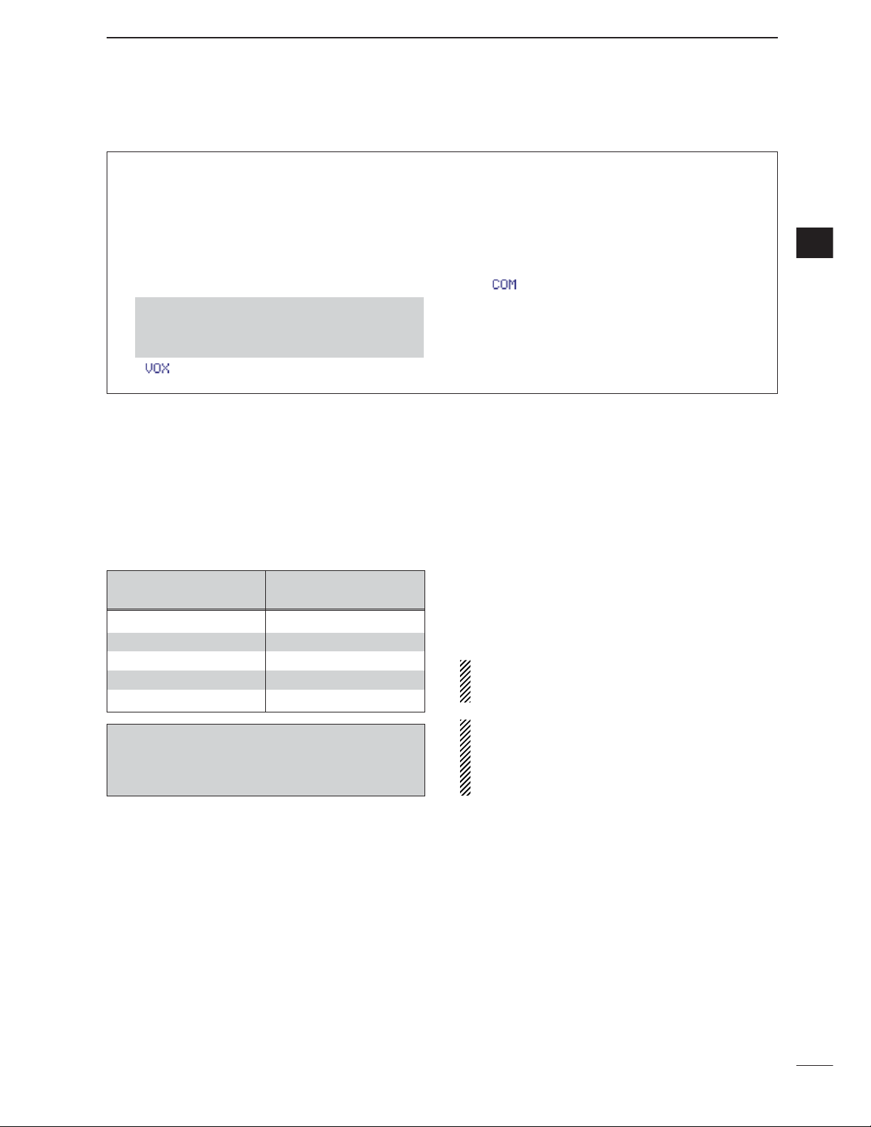
40
4
RECEIVE AND TRANSMIT
4
D Convenient functions for transmit
• Transmit quality monitor (p. 89)
➥ Push [AF(
SET
)], then [F-4
OTH
] to enter the mis-
cellaneous (others) set mode. Select an item with
[F-1≤]/[F-2≥], then rotate [DIAL] to turn the
monitor function ON and OFF.
• VOX (voice operated transmit) (p. 85)
➥ While “
M
-
3
” is selected, push [F-1
VOX
] to turn
the VOX function ON and OFF.
• “ ” appears when the VOX function is set to ON.
➥ While “
M
-
3
” is selected, push [F-1
VOX
] for 1
sec. to enter the VOX set mode.
•Push [F-1≤]/[F-2≥] to select an item.
•Rotate [DIAL] to set the value/conditions.
• Speech compressor (p. 89)
➥ While “
M
-
3
” is selected, push [F-2
COM
] to turn
the speech compressor ON and OFF.
• “”appears when the speech compressor is set to
ON.
➥ While “
M
-
3
” is selected, push [F-2
COM
] for 1
sec. to enter the compression level set mode.
•Rotate [DIAL] to adjust the compression level.
•Push and hold [MENU/GRP] for 1 sec. once or twice
to select the menu group M.
•Push [MENU/GRP] momentarily one or more times
to select the menu
M
-
3
.
D
About 5 MHz band operation (USA version only)
Operation on the 5 MHz band is allowed on 5 discrete
frequencies and must adhere to the following:
• USB mode
• Maximum of 50 watts ERP
(Effective Radiated Power)
• 2.8 kHz bandwidth
It is the operator’s responsibility to set all controls so
that the transmission in this band meets the stringent
conditions under which we may use these frequencies.
NOTE: We recommend that you store these frequencies, mode and filter settings into the memory
channel for easy recall.
*The channel center frequencies that are specified
by the FCC, show the center frequency of their
passband. However, the IC-7000 displays carrier
point frequency, so set 1.5 kHz below from FCC
channel center frequency.
IC-7000 Tuning FCC Channel
Frequency* Center Frequency*
5.33050 MHz 5.33200 MHz
5.34650 MHz 5.34800 MHz
5.36650 MHz 5.36800 MHz
5.37150 MHz 5.37300 MHz
5.40350 MHz 5.40500 MHz
To assist you in operating the 5 MHz band correctly
within the rules specified by the FCC, transmission
is impossible on any 5 MHz band frequency other
than the 5 frequencies indicated in the table above.
Page 50

41
4
RECEIVE AND TRANSMIT
■ Operating CW
q Connect a paddle or straight key as on page 22.
w Push [Y(
BAND
)]/[Z(
BAND
)] to select the desired
band or push a band key on the HM-151.
e Push [MODE] momentarily to select CW mode.
•After CW mode is selected, push [MODE] for 1 sec. to
toggle between CW and CW-R modes.
r Rotate [DIAL] to tune in a desired signal with the
desired tone frequency.
t Rotate [AF] to set audio to a comfortable listening
level.
y Set CW break-in operation as semi break-in, full
break-in or OFF.
•Push [F-1
BRK
] one or more times to select the CW
break-in operation.
• “,” “,” and “OFF (no indication)” appears.
➧ BK-IN: semi break-in
➧ F-BK : full break-in
➧ OFF : no break-in (ACC socket connection is neces-
sary as shown on page 22.)
u Set the CW delay time when semi break-in opera-
tion is selected.
•Push [F-1
BRK
] for 1 sec. to enter the break-in delay
time set mode.
•Rotate [DIAL] to set the desired delay time.
i Set CW setting in the keyer set mode (
S
-
1
).
•Push [F-2
KEY
], [Z(
MENU/GRP
)], then [F-4
SET
] to
enter the keyer set mode. (p. 49)
o Keying to transmit, use the electric keyer or paddle
to send your CW signals.
• [TX] indicator lights red.
• The Po meter indicates transmitted CW signal strength.
!0 Stop keying to return to receive.
Delay time of 7.5 dots is selected
for semi break-in operation.
Semi break-in operation is selected.
Appears
“CW” or “CW-R” appears
[Y]
[Z]
[DIAL]
[MODE][AF] [TX] indicator
[MENU/GRP] [F-4][F-1] [F-2]
•Push and hold [MENU/GRP] for 1 sec. once or twice
to select the menu group S.
•Push [MENU/GRP] momentarily one or more times to
select the menu
S
-
1
.
•Push and hold [MENU/GRP] for 1 sec. once or twice
to select the menu group M.
•Push [MENU/GRP] momentarily one or more times to
select the menu
M
-
3
.
Page 51

42
4
RECEIVE AND TRANSMIT
4
D Convenient functions for receive
• Preamp and attenuator (p. 74)
➥ Push [P.AMP/ATT] momentarily to turn the pre-
amp ON or OFF.
• “ ” appears when the preamp is set to ON.
➥ Push [P.AMP/ATT] for 1 sec. to turn the attenua-
tor ON.
•Push [P.AMP/ATT] momentarily to turn the attenuator
OFF.
• “ ” appears when the attenuator is set to ON.
• Twin PBT (passband tuning) (p. 79)
➥ Push [PBT/M-ch/RIT] (switch) momentarily once
or twice to select the twin PBT ON or OFF (M-ch
RIT).
•PBT indicator lights green when the twin PBT is selected.
➥ Rotate [PBT/M-ch/RIT] (controls–inner/outer).
•Push [PBT/M-ch/RIT(
CLR
)] to clear the settings.
• AGC (auto gain control) (p. 76)
➥ While “
M
-
3
” is selected, push [F-3
AGC
] momentarily one or more times to select AGC fast, AGC
middle and AGC slow.
•“ ,” “ ” and “ ” appears when the
fast time constant, middle time constant and slow
time constant is selected, respectively.
➥ While “
M
-
3
” is selected, push [F-3
AGC
] for 1
sec. to enter the AGC set mode.
•Push [F-2
FAST
], [F-3
MID
] or [F-4
SLOW
] to select
the time constant, then rotate [DIAL] to adjust the time
constant.
• Noise blanker (p. 80)
➥ Push [NB/ADJ] to turn the noise blanker ON and
OFF.
• “ ” appears when the noise blanker is set to ON.
➥ Push [NB/ADJ] for 1 sec. to enter the noise
blanker set mode, then rotate [DIAL] to adjust the
threshold level, or noise pulse width.
• DSP noise reduction (p. 81)
➥ Push [NR/LEV] to turn the DSP noise reduction
ON and OFF.
• “ ” appears when the DSP noise reduction is set to
ON.
➥ Push [NR/LEV] for 1 sec. to enter the noise re-
duction level set mode, then rotate [DIAL] to adjust the DSP noise reduction level.
• Manual notch filter (pgs. 82, 83)
➥ Push [MNF/ADJ] to turn the manual notch filter
ON and OFF.
•“ ” appears when the manual notch filter is set to
ON.
➥ Push [MNF/ADJ] for 1 sec. to enter the manual
notch filter set mode.
•Push [F-2
NF1
], [F-3
NF2
] to select the notch filter,
push [F-4NW] to set the filter width, rotate [DIAL] to
set the attenuating frequency.
•1⁄4 function (p. 32)
➥ While “
M
-
3
” is selected, push [F-2
1/4
] to turn
the
1
⁄4 function ON and OFF.
• “ ” indicator appears when the function is activate.
•Push and hold [MENU/GRP] for 1 sec. once or twice
to select the menu group M.
•Push [MENU/GRP] momentarily one or more times
to select the menu
M
-
3
.
• Break-in function (p. 87)
➥ While “
M
-
3
” is selected, push [F-1
BRK
] one or
more times to select the CW break-in operation.
• “ ” or “ ” appears when the semi break-in or
full break-in is set to ON, respectively.
• Memory keyer function (p. 45)
➥ While “
S
-
1
” is selected, push [F-2
KEY
] to enter
the keyer set memu.
•Push and hold [MENU/GRP] for 1 sec. once or twice
to select the menu group M.
•Push [MENU/GRP] momentarily one or more times
to select the menu
M
-
3
.
D Convenient functions for transmit
Page 52

43
4
RECEIVE AND TRANSMIT
D CW reverse mode
The CW-R (CW Reverse) mode receives CW signals
on the reverse sideband like that of LSB and USB
modes.
Use when interference is near the desired signal and
you want to change the interference tone.
q Push [MODE] several times to select CW mode.
w
Push [MODE] for 1 sec. to select CW or CW-R
mode.
• Check the interference tone.
• Receive audio tone response
CW-R mode (USB side)CW mode (LSB side)
BFO
600 Hz
signal
inteference
signal
600 Hz
BFO
inteference
Push
for 1 sec.
[MODE]
D
CW side tone function
When the transceiver is in receive condition (and the
break-in function is OFF— p. 87) you can listen to the
tone of your CW signal without actually transmitting.
This allows you to match your transmit signal exactly
to another station’s. This also convenient for CW
practice.
q When CW (CW-R) mode is selected, enter the
quick set mode.
•Push [AF(
SET
)] momentarily to enter the set mode
menu.
•Push [F-1QS] to enter the quick set mode.
w Push [F-1≤] or [F-2≥] several times to select
“
Side Tone Level
,” then rotate [DIAL] to ad-
just the side tone level.
•Side tone level is adjusted in 1% steps (0% to 100%).
e Push [Z(
MENU/GRP
)] to exit the quick set mode.
•Push [Z(
MENU/GRP
)] again to return the normal oper-
ating mode.
[DIAL][MENU/GRP] [F-1] [F-2]
[AF]
Page 53

44
4
RECEIVE AND TRANSMIT
4
D CW pitch control
The received CW audio pitch and monitored CW
audio pitch can be adjusted to suit your preferences
(300 to 900 Hz) without changing the operating frequency.
q When CW (CW-R) mode is selected, enter the
quick set mode.
•Push [AF(
SET
)] momentarily to enter the set mode
menu.
•Push [F-1QS] to enter the quick set mode.
w Push [F-1≤] or [F-2≥] several times to select “
CW
Pitch
,” then rotate [DIAL] to set the desired
pitch.
•CW pitch is adjusted in 5 Hz steps (300 to 900 Hz).
e Push [Z(
MENU/GRP
)] to exit the quick set mode.
•Push [Z(
MENU/GRP
)] again to return the normal oper-
ating mode.
•This shows the default setting for the CW pitch control
(600 Hz).
[DIAL][MENU/GRP] [F-1] [F-2]
[AF]
Page 54

45
4
RECEIVE AND TRANSMIT
■ Electronic CW keyer
The IC-7000 has a number of convenient functions for
the electronic keyer that can be accessed from the
memory keyer menu.
q Push [MODE] to select CW mode.
w Select
S
-
1
.
e Push [F-2
KEY
] to enter the keyer send menu.
r Push [Z(
MENU/GRP
)] to select the keyer root menu.
t Push one of the multi-function keys ([F-1] to [F-4])
to select the desired menu. See the diagram below.
•Push [Z(
MENU
/
GRP
)] to return to the previous indica-
tion.
[MODE]
[DIAL][DIAL][MENU/GRP]
[F-1]
[F-2] [F-3] [F-4]
¡Memory keyer root menu
¡Memory keyer send menu
¡Memory keyer edit menu
¡Contest number set mode
¡Keyer set mode
Memory keyer root menu can also be set to
the starting menu for keyer operation in the
miscellaneous (others) set mode. (p.136)
Page 55

46
4
RECEIVE AND TRANSMIT
4
Pre-set characters can be sent using the memory
keyer send menu. Contents of the memory keyer are
set using the edit menu.
• Transmitting
q Select CW mode with [MODE].
w Set the break-in function ON (p. 87).
•When step t is performed with the break-in function
OFF, the memory keyer contents are monitored.
e Select
S
-
1
.
r Push [F-2
KEY
] to enter the keyer send menu.
•If the keyer root menu appears, push [F-1
SND
]. The
keyer starting menu can be changed in the miscellaneous (others) set mode (p. 136).
t Push [F-1M1] — [F-4M4] momentarily to transmit
the contents one time; push these keys for 1 sec.
to transmit the contents repeatedly.
•“M1”– “M4” are highlighted while transmitting.
•“(” and “)” appear while transmitting repeatedly.
•While transmitting repeatedly, push any function key to
cancel the transmission.
•Set the repeat interval of the memory keyer to 1–60
sec. (1 sec. steps). See p. 49 for keyer set mode.
•To decrement the contact number, push
[Y(
MENU/GRP
)].
y Push [Z(
MENU/GRP
)] twice to exit the memory
keyer send menu and return to normal CW mode
indication.
• Memory keyer send menu
Memory keyer
content
Contact number
[MODE]
[MENU/GRP]
[F-1]
[F-2] [F-3] [F-4]
D Memory keyer send menu
Menu group selection
Push [MENU/GRP] for 1 sec.
Selection from:
M,SorG
(Graphic)
Menu selection (Example: S)
Push [MENU/GRP] momentarily.
Selection from:
S-1,S-2orS-3
Y or Z
Y or Z
Either
Either
Page 56

47
4
RECEIVE AND TRANSMIT
D
Editing a keyer memory
The contents of the memory keyer memories can be
set using the memory keyer edit menu. The memory
keyer can memorize and re-transmit 4 CW sequences for often-used CW sentences, contest number, etc. Total capacity of the memory keyer is 55
characters per memory channel.
• Pre-programmed contents
• Programming contents
q Push [MODE] to select CW mode.
w Select
S
-
1
.
e Push [F-2
KEY
] then [Z(
MENU
/
GRP
)] to select the
keyer root menu.
•If the keyer root menu appears, skip pushing
[Z(
MENU/GRP
)]. The keyer starting menu can be
changed in the miscellaneous (others) set mode.
r Push [F-2
EDT
] to enter the keyer edit menu.
t Push [F-1M1] — [F-4M4] to select the desired
keyer memory channel.
y Push [Y(
MENU/GRP
)] several times to select the de-
sired character group ([ABC], [123] or [etc]).
•Selectable characters (with [DIAL]);
NOTE:
“
^” is used to transmit a following word with no
space such as
AR
. Put “^” before a text string
such as ^AR, and the CW prosign “ ” is sent
with no space.
“
✱” is used to insert the CW contest number.
The contest number automatically increments
by 1. This function is only available for one
memory keyer channel at a time. Memory
keyer channel M2 uses “
✱” by default.
u Select the desired character by rotating [DIAL] or
by pushing the band key (HM-151) for the incrementing trigger memory number input.
•Push[F-1Å] or [F-2Ç] for cursor movement.
•Push[F-3
DEL
] to delete the selected character.
•Push[F-4
SPC
] to input a space.
•“✱” is for contact numbers and can be input for the
count up trigger channel (“ ” appears).
i Repeat steps y and u until the desired contents
are input.
o Push [Z(
MENU/GRP
)] to return to memory channel
selection mode, then select the next memory channel and repeat steps y and i for character input,
if desired.
!0 Push [Z(
MENU/GRP
)] twice to exit the keyer edit
mode.
•Push and hold [MENU/GRP] for 1 sec. once or twice
to select the menu group S.
•Push [MENU/GRP] momentarily one or more times to
select the menu
S
-
1
.
CH Contents
CQ TEST CQ TEST DE ICOM ICOM TEST
UR 5NN✽ BK
CFM TU
M1
M2
M3
QRZ?
M4
Memory channel select
Selected
character
[MENU/GRP]
[F-1]
[F-2] [F-3] [F-4]
Key selection
Editable characters
ABC
123
etc
A to Z (capital leters)
0 to 9 (numbers)
/ ?^. , @ ✽
AR
Page 57

48
4
RECEIVE AND TRANSMIT
4
2
Count UP Trigger
This selects which of the four memory channels will
have the contest serial number exchange. The count
up trigger increments the serial number automatically
after each complete serial number exchange is sent.
• M1, M2, M3 and M4 can be set. (default: M2)
1
Number Style
This item sets the numbering system used for contest
(serial) numbers— normal or cut numbers.
Normal : Does not use morse cut number
(default)
190➜ANO: Sets 1 as A, 9 as N and 0 as O.
190➜ANT : Sets 1 as A, 9 as N and 0 as T.
90➜ NO : Sets 9 as N and 0 as O.
90➜ NT : Sets 9 as N and 0 as T.
3
Present Number
This item shows the current number in the count up
trigger channel set above.
•Rotate [DIAL] to change the number, or push [F-4
CLR
] for 1sec. to reset the current number to 001.
This menu is used to set the contest (serial) number
and incrementing trigger channel, etc.
• Setting the contact (serial) number
Contact number can be automatically transmitted
from one of the memory keyer channels. The Morse
cut numbers can be used as the contact numbers.
The maximum number for contact numbers is 9999.
q Select CW mode with [MODE].
w Select
S
-
1
.
e Push [F-2
KEY
] then [Z(
MENU/GRP
)] to select the
keyer root menu.
r Push [F-3
001
] to enter the contest number set
menu.
t Push [F-1≤] or [F-2≥] to select the desired set
item.
•Push [F-4
DEF
] for 1 sec. to select the default condi-
tion or value.
y Push [Z(
MENU/GRP
)] twice to exit the contest num-
ber set menu and return to normal CW mode indication.
•Push and hold [MENU/GRP] for 1 sec. once or twice
to select the menu group S.
•Push [MENU/GRP] momentarily one or more times to
select the menu
S
-
1
.
[MODE]
[MENU/GRP]
[F-1]
[F-2] [F-3] [F-4]
D Contest number set mode
Page 58

49
4
RECEIVE AND TRANSMIT
This set mode is used to set the memory keyer repeat
time, dash weight, paddle specifications, keyer type,
etc.
• Setting the electronic keyer
q Select CW mode with [MODE].
w Select
S
-
1
.
e Push [F-2
KEY
] then [Z(
MENU
/
GRP
)] to select the
keyer root menu.
r Push [F-4
SET
] to enter the keyer set menu.
t Push [F-1≤] or [F-2≥] to select the desired set
item.
•Push [F-4
DEF
] for 1 sec. to select the default condi-
tion or value.
y Push [Z(
MENU/GRP
)] twice to exit the keyer set
menu and return to normal CW mode indication.
•Push and hold [MENU/GRP] for 1 sec. once or twice
to select the menu group S.
•Push [MENU/GRP] momentarily one or more times to
select the menu
S
-
1
.
[MODE]
[MENU/GRP]
[F-1]
[F-2] [F-3] [F-4]
D Keyer set mode
1
Keyer Repeat Time
When sending CW using the repeat timer, this item
sets the time between transmission.
•1 to 60 sec. in 1 sec. steps can be selected.
•Push [F-4
DEF
] for 1 sec. to select a default setting.
(default: 2 sec.)
2
Dot/Dash Ratio
This item sets the dot/dash ratio.
• 1:1:2.8 to 1 : 1 : 4.5 can be set.
• Check the ratio with side tone in CW mode.
•Push [F-4
DEF
] for 1 sec. to select a default ratio of
1:1:3.0.
Keying weight example: Morse code “K”
DASH
Weight setting:
1:1:3 (default)
Weight setting:
Adjusted
DASH
DOT (Fixed*)
Adjustable range SPACE (Fixed*)
*SPACE and DOT length can be adjusted with
“Key Speed” only in the quick set mode.
Page 59

50
4
RECEIVE AND TRANSMIT
4
D
Keyer set mode (continued)
3
Rise Time
This item sets the envelop time period which the output power becomes the set transmit power.
•2, 4, 6, or 8 msec. can be selected.
•Push [F-4
DEF
] for 1 sec. to select a default setting.
(default: 4 sec.)
Key action
Tx output power
• About rise time
Rise time
Tx
Rx
Set Tx power level
Time
0
4
Paddle Polarity
This item sets the paddle polarity.
•Normal and reverse polarity can be selected.
•Push [F-4
DEF
] for 1 sec. to select a default setting.
(default: Normal)
5
Keyer Type
This item selects the keyer type for [KEY] connector
on the rear panel.
•ELEC-KEY, BUG-KEY and Straight key can be selected.
•Push [F-4
DEF
] for 1 sec. to select a default setting.
(default: ELEC-KEY)
6
MIC U/D Keyer (HM-103)
(Microphone’s [UP]/[DN] switches keyer)
This item allows you to set the microphone [UP]/[DN]
switches to be used as a paddle.
•ON : [UP]/[DN] switches can be used for CW.
•OFF: [UP]/[DN] switches cannot be used for CW.
•Push [F-4
DEF
] for 1 sec. to select a default setting.
(default: OFF)
NOTE: When “ON” is selected, the frequency and
memory channel cannot be changed using the
[UP]/[DN] switches.
Connect a CW paddle as at right to operate an electronic keyer from [MIC] connector.
•This function is available from both of the front panel
and rear panel mic connector.
•Be sure to select “Paddle Polarity” and “Keyer Type”
in the keyer set mode. (see above)
• Connect straight key to “DOT” side.
MIC connector
MIC U/D
CW
paddle
DOT
E
DASH
w
u
3.9 k1 ±5%
2.2 k1 ±5%
D Paddle operation from [MIC] connector
Page 60

■ Operating RTTY (FSK)
When using your RTTY terminal or TNC, consult the
manual that comes with the RTTY terminal or TNC.
q Push [Y(
BAND
)]/[Z(
BAND
)] to select the desired
band or push a band key on the HM-151.
w Push [MODE] momentarily to select RTTY mode.
•After RTTY mode is selected, push [MODE] for 1 sec.
to toggle between RTTY and RTTY-R modes.
e Display the RTTY decoder screen.
•Push [F-2
DEC
] to display the Baudot decoder screen.
r Rotate [DIAL] to simultaneously tune a desired sig-
nal.
•Use [F-2
1/4
] in the
M
-
3
display when critical setting
is required.
•S-meter indicates received signal strength when signal
is received.
•If the received signal cannot be demodulated, try selecting RTTY-R mode (or RTTY mode).
t Transmit a SEND signal from your TNC.
•[TX] indicator lights red.
•The Po meter indicates transmitted RTTY signal
strength.
y Operate the connected PC or TNC (TU) to trans-
mit RTTY (FSK) signals.
“RTTY” or “RTTY-R” appears
[Y]
[Z]
[DIAL]
[MODE][AF] [TX] indicator
[MENU/GRP] [F-2]
•Push and hold [MENU/GRP] for 1 sec. once or twice
to select the menu group S.
•Push [MENU/GRP] momentarily one or more times to
select the menu
S
-
1
.
51
4
RECEIVE AND TRANSMIT
Page 61
52
4
RECEIVE AND TRANSMIT
4
• Preamp and attenuator (p. 74)
➥ Push [P.AMP/ATT] momentarily to turn the pre-
amp ON or OFF.
• “ ” appears when the preamp is set to ON.
➥ Push [P.AMP/ATT] for 1 sec. to turn the attenua-
tor ON.
•Push [P.AMP/ATT] momentarily to turn the attenuator
OFF.
• “ ” appears when the attenuator is set to ON.
• Twin PBT (passband tuning) (p. 79)
➥ Push [PBT/M-ch/RIT] (switch) momentarily once
or twice to select the twin PBT ON or OFF (M-ch
RIT).
•PBT indicator lights green when the twin PBT is selected.
➥ Rotate [PBT/M-ch/RIT] (controls–inner/outer).
•Push [PBT/M-ch/RIT(
CLR
)] to clear the settings.
• AGC (auto gain control) (p. 76)
➥ While “
M
-
3
” is selected, push [F-3
AGC
] momentarily one or more times to select AGC fast, AGC
middle and AGC slow.
•“ ,” “ ” and “ ” appears when the
fast time constant, middle time constant and slow
time constant is selected, respectively.
➥ While “
M
-
3
” is selected, push [F-3
AGC
] for 1
sec. to enter the AGC set mode.
•Push [F-2
FAST
], [F-3
MID
] or [F-4
SLOW
] to select
the time constant, then rotate [DIAL] to adjust the time
constant.
• Noise blanker (p. 80)
➥ Push [NB/ADJ] to turn the noise blanker ON and
OFF.
• “ ” appears when the noise blanker is set to ON.
➥ Push [NB/ADJ] for 1 sec. to enter the noise
blanker set mode, then rotate [DIAL] to adjust the
threshold level, or noise pulse width.
• DSP noise reduction (p. 81)
➥ Push [NR/LEV] to turn the DSP noise reduction
ON and OFF.
•“ ” appears when the DSP noise reduction is set to
ON.
➥ Push [NR/LEV] for 1 sec. to enter the noise re-
duction level set mode, then rotate [DIAL] to adjust the DSP noise reduction level.
• Manual notch filter (pgs. 82, 83)
➥ Push [MNF/ADJ] to turn the manual notch filter
ON and OFF.
•“ ” appears when the manual notch filter is set to
ON.
➥ Push [MNF/ADJ] for 1 sec. to enter the manual
notch filter set mode.
•Push [F-2
NF1
], [F-3
NF2
] to select the notch filter,
push [F-4NW] to set the filter width, rotate [DIAL] to
set the attenuating frequency.
•1⁄
4 function (p. 32)
➥ While “
M
-
3
” is selected, push [F-2
1/4
] to turn
the
1
⁄
4 function ON and OFF.
• “ ” indicator appears when the function is activate.
•Push and hold [MENU/GRP] for 1 sec. once or twice
to select the menu group M.
•Push [MENU/GRP] momentarily one or more times
to select the menu
M
-
3
.
D Convenient functions for receive
Page 62

53
4
RECEIVE AND TRANSMIT
D RTTY reverse mode
Received characters are occasionally garbled when
the receive signal is reversed between MARK and
SPACE. This reversal can be caused by incorrect
TNC connections, settings, commands, etc.
To receive a reversed RTTY signal correctly, select
RTTY-R (RTTY reverse) mode.
q Push [MODE] several times to select RTTY mode.
w
Push [MODE] for 1 sec. to select RTTY or RTTY-R
mode.
ReverseNormal
BFO
170
Hz
2125
Hz
170
Hz
2125
Hz
BFO
Mark
Space
displayed freq.displayed freq.
Mark
Space
[MODE]
D
Twin peak filter
The twin peak filter changes the receive frequency response by boosting 2 particular frequencies
(2125 and
2295 Hz)
for better copying of desired RTTY signals.
q Push [MODE] momentarily to select RTTY mode.
•After RTTY mode is selected, push [MODE] for 1 sec.
to toggle between RTTY and RTTY-R modes.
w Push [AF(
SET
)] momentarily to enter the set mode
menu.
e Push [F-1QS] to enter the quick set mode.
r Push [F-1≤] or [F-2≥] to select “
Twin Peak
Filter
.”
t Rotate [DIAL] to select the twin peak filter function
ON or OFF.
•The received audio volume may become greater when
the twin peak filter is turned ON.
y Push [Z(
MENU/GRP
)] twice to return the normal op-
erating mode.
[DIAL][MENU/GRP] [F-1] [F-2]
[AF]
Page 63

54
4
RECEIVE AND TRANSMIT
4
D
Function for the RTTY decoder indication
The transceiver has an RTTY decoder for Baudot
(mark freq.: 2125 Hz, shift freq.: 170 Hz, 45 bps).
An external terminal unit (TU) or terminal node controller (TNC) is not necessary for receiving a Baudot
signal.
q Push [MODE] momentarily to select RTTY mode.
•After RTTY mode is selected, push [MODE] for 1 sec.
to toggle between RTTY and RTTY-R modes.
w Select
S
-
1
.
e Push [F-2
DEC
] momentarily to turn the RTTY de-
coder ON.
•When tuned into an RTTY signal, decoded characters
are displayed in the RTTY decoder screen.
r Push [F-1
HLD
] momentarily to freeze the current
screen.
•“H” appears while the function is in use.
t Push [Y(
MENU/GRP
)] to toggle the normal or wide
screen space.
y Push [F-1
HLD
] for 1 sec. to clear the displayed
characters.
u Push [Z(
MENU/GRP
)] to exit the RTTY decoder
screen.
The transceiver has an RTTY tuning iindicator to
make correct tuning easier.
The RTTY tuning meter is automatically displayed
when the RTTY decoder is turned ON.
•Push and hold [MENU/GRP] for 1 sec. once or twice
to select the menu group S.
•Push [MENU/GRP] momentarily one or more times to
select the menu
S
-
1
.
RTTY tuning meter
[MENU/GRP] [F-1] [F-2]
D
Setting the decoder threshold level
Adjust the RTTY decoder threshold level if some
characters are displayed when no signal is received.
q Call up the RTTY decoder screen as described
above.
w Push [F-3
ADJ
] to select the threshold level set-
ting condition.
e Rotate [DIAL] to adjust the RTTY decoder thresh-
old level.
•Push [F-4
DEF
] for 1 sec. to select the default condi-
tion.
r Push [Z(
MENU/GRP
)] to exit the RTTY decoder
screen.
The UnShift On Space (USOS) function and new
line code can be set in the RTTY decode set mode.
(p. 55)
[DIAL][MENU/GRP] [F-3] [F-4]
Page 64

55
4
RECEIVE AND TRANSMIT
D
RTTY decode set mode
This set mode is used to set the decode USOS function, etc.
q Push [MODE] momentarily to select RTTY mode.
•After RTTY mode is selected, push [MODE] for 1 sec.
to toggle between RTTY and RTTY-R modes.
w Select
S
-
1
.
e Push [F-2
DEC
] momentarily to turn the RTTY de-
coder ON.
• RTTY decoder screen appears.
r Push [F-4
SET
] to select the RTTY decode set
mode.
t Push [F-1≤] or [F-2≥] to select the desired set
item.
y Set the desired condition using [DIAL].
•Push [F-4
DEF
] for 1 sec. to select a default condition
or value.
u Push [Z(
MENU/GRP
)] to exit from set mode.
•Push and hold [MENU/GRP] for 1 sec. once or twice
to select the menu group S.
•Push [MENU/GRP] momentarily one or more times to
select the menu
S
-
1
.
[MENU/GRP] [F-1] [F-2] [F-4] [DIAL]
1
RTTY Decode USOS
This item selects the USOS (UnShift On Space) function of the internal RTTY decoder.
ON
Decode as letter code
(default)
OFF
Decode as character code
2
RTTY Decode New Line Code
This item selects the new line code of the internal
RTTY decoder.
CR : Carriage Return
LF : Line Feed
CR,LF,CR+LF
CR, LF and CR+LF
(default)
CR+LF
CR+LF only
Page 65

56
4
RECEIVE AND TRANSMIT
4
D Pre-setting for using RTTY terminal or TNC
When using your RTTY terminal or TNC, consult the
manual that comes with the RTTY terminal or TNC.
Mark frequency
q Push [MODE] momentarily to select RTTY mode.
•After RTTY mode is selected, push [MODE] for 1 sec.
to toggle between RTTY and RTTY-R modes.
w Push [AF(
SET
)] momentarily to enter the set mode
menu.
e Push [F-1QS] to enter the quick set mode.
r Push [F-1 Y] or [F-2 Z] to select “
RTTY Mark
Frequency
.”
t Rotate [DIAL] to select the desired frequency.
•Push [F-4
DEF
] for 1 sec. to select the default fre-
quency.
Shift width
q Enter the quick set mode as same as above.
w Push [F-1 Y] or [F-2 Z] to select “
RTTY Shift
Width
.”
e Rotate [DIAL] to select the desired shift width.
•Push [F-4
DEF
] for 1 sec. to select the default shift
width.
RTTY keying polarity
q Enter the quick set mode as same as above.
w Push [F-1 Y] or [F-2 Z] to select “
RTTY key-
ing Polarity
.”
e Rotate [DIAL] to select the desired keying polarity.
•Push [F-4
DEF
] for 1 sec. to select the default polarity.
After Pre-setting is finished, push [Z(
MENU/GRP
)] mo-
mentarily twice to return the normal operating mode.
RTTY keying is set to
‘normal’. (default)
normal :
key open=mark
key close=space
reverse:
key open=space
key close=mark
RTTY shift width is
set to 170 Hz.
(default)
170/200/425 Hz are
available.
RTTY mark frequency
is set to 2125 Hz.
(default)
2125, 1615 and 1275
Hz are available.
[MODE][AF]
[MENU/GRP] [F-1] [F-2] [F-4] [DIAL]
Page 66

57
4
RECEIVE AND TRANSMIT
■ Operating AM
q Push [Y(
BAND
)]/[Z(
BAND
)] to select the desired
band or push a band key on the HM-151.
w Push [MODE] momentarily or push and hold for 1
sec. to select AM mode.
•After FM, WFM or AM mode is selected, push [MODE]
for 1 sec. to select from FM, WFM and AM modes.
e Rotate [DIAL] to tune in a desired signal.
•The S-meter indicates received signal strength when a
signal is received.
•The default tuning step for AM mode is 1 kHz; this can
be changed using the tuning step program mode. (p. 30)
r Rotate [AF] to set audio to a comfortable listening
level.
t Push [PTT] (microphone) to transmit.
•[TX] indicator lights red.
y Speak into the microphone at your normal voice
level.
•Adjust ‘MIC Gain’ at this step, if necessary. (p. 38)
u Release [PTT] (microphone) to return to receive.
“AM” appears
[Y]
[Z]
[DIAL]
[MODE][AF] [TX] indicator
D Convenient functions for receive
• Preamp and attenuator (p. 74)
➥ Push [P.AMP/ATT] momentarily to turn the pre-
amp ON or OFF.
• “ ” appears when the preamp is set to ON.
➥ Push [P.AMP/ATT] for 1 sec. to turn the attenua-
tor ON.
•Push [P.AMP/ATT] momentarily to turn the attenuator
OFF.
• “ ” appears when the attenuator is set to ON.
• Twin PBT (passband tuning) (p. 79)
➥ Push [PBT/M-ch/RIT] (switch) momentarily once
or twice to select the twin PBT ON or OFF (M-ch
RIT).
•PBT indicator lights green when the twin PBT is selected.
➥ Rotate [PBT/M-ch/RIT] (controls–inner/outer).
•Push [PBT/M-ch/RIT(
CLR
)] to clear the settings.
• Noise blanker (p. 80)
➥ Push [NB/ADJ] to turn the noise blanker ON and
OFF.
• “ ” appears when the noise blanker is set to ON.
➥ Push [NB/ADJ] for 1 sec. to enter the noise
blanker set mode, then rotate [DIAL] to adjust the
threshold level, or noise pulse width.
• AGC (auto gain control) (p. 76)
➥ While “
M
-
3
” is selected, push [F-3
AGC
] momentarily one or more times to select AGC fast, AGC
middle and AGC slow.
•“ ,” “ ” and “ ” appears when the
fast time constant, middle time constant and slow
time constant is selected, respectively.
➥ While “
M
-
3
” is selected, push [F-3
AGC
] for 1
sec. to enter the AGC set mode.
•Push [F-2
FAST
], [F-3
MID
] or [F-4
SLOW
] to select
the time constant, then rotate [DIAL] to adjust the time
constant.
•Push and hold [MENU/GRP] for 1 sec. once or twice
to select the menu group M.
•Push [MENU/GRP] momentarily one or more times
to select the menu
M
-
3
.
Page 67

58
4
RECEIVE AND TRANSMIT
4
Convenient functions for receive (continued)
• DSP noise reduction (p. 81)
➥ Push [NR/LEV] to turn the DSP noise reduction
ON and OFF.
• “ ” appears when the DSP noise reduction is set to
ON.
➥ Push [NR/LEV] for 1 sec. to enter the noise re-
duction level set mode, then rotate [DIAL] to adjust the DSP noise reduction level.
• Manual notch filter (pgs. 82, 83)
➥ Push [MNF/ADJ] to turn the manual notch filter
ON and OFF.
•“ ” appears when the manual notch filter is set to
ON.
➥ Push [MNF/ADJ] for 1 sec. to enter the manual
notch filter set mode.
•Push [F-2
NF1
], [F-3
NF2
] to select the notch filter,
push [F-4NW] to set the filter width, rotate [DIAL] to
set the notch frequency.
• Auto notch filter (p. 82)
➥ Push [ANF/•REC] to turn the auto notch filter ON
and OFF.
• “ ” appears when the auto notch filter is set to ON.
• VSC (voice squelch control) (p. 84)
➥ While “
S
-
1
” is selected, push [F-4
VSC
] to turn
the VSC function ON and OFF.
• “”appears when VSC function is set to ON.
D Convenient functions for transmit
• Transmit quality monitor (p. 89)
➥ Push [AF(
SET
)], then [F-4
OTH
] to enter the mis-
cellaneous (others) set mode. Select an item with
[F-1≤]/[F-2≥], then rotate [DIAL] to turn the
monitor function ON and OFF.
• VOX (voice operated transmit) (p. 85)
➥ While “
M
-
3
” is selected, push [F-1
VOX
] to turn
the VOX function ON and OFF.
• “ ” appears when the VOX function is set to ON.
➥ While “
M
-
3
” is selected, push [F-1
VOX
] for 1
sec. to enter the VOX set mode.
•Push [F-1≤]/[F-2≥] to select an item.
•Rotate [DIAL] to set the value/conditions.
•Push and hold [MENU/GRP] for 1 sec. once or twice
to select the menu group M.
•Push [MENU/GRP] momentarily one or more times
to select the menu
M
-
3
.
Page 68

59
4
RECEIVE AND TRANSMIT
■ Operating FM
q Push [
Y
(
BAND
)]/[
Z
(
BAND
)] to select the desired
band or push a band key on the HM-151.
w Push [MODE] momentarily or push and hold for 1
sec. to select FM mode.
•After FM, WFM or AM mode is selected, push [MODE]
for 1 sec. to select from FM, WFM and AM modes.
e Rotate [DIAL] to tune in a desired signal.
•The S-meter indicates received signal strength when a
signal is received.
•The default tuning step for FM mode is 1 kHz; this can
be changed using the tuning step program mode. (p. 30)
r Rotate [AF] to set audio to a comfortable listening
level.
t Push [PTT] (microphone) to transmit.
•[TX] indicator lights red.
y Speak into the microphone at your normal voice
level.
•Adjust ‘MIC Gain’ at this step, if necessary. (p. 38)
u Release [PTT] (microphone) to return to receive.
“FM” appears
[Y]
[Z]
[DIAL]
[MODE][AF] [TX] indicator
D Convenient functions for receive
• Preamp and attenuator (p. 74)
➥ Push [P.AMP/ATT] momentarily to turn the pre-
amp ON or OFF.
• “ ” appears when the preamp is set to ON.
➥ Push [P.AMP/ATT] for 1 sec. to turn the attenua-
tor ON.
•Push [P.AMP/ATT] momentarily to turn the attenuator
OFF.
• “ ” appears when the attenuator is set to ON.
• Auto notch filter (p. 82)
➥ Push [ANF/•REC] to turn the auto notch filter ON
and OFF.
• “ ” appears when the auto notch filter is set to ON.
• DSP noise reduction (p. 81)
➥ Push [NR/LEV] to turn the DSP noise reduction
ON and OFF.
• “ ” appears when the DSP noise reduction is set to
ON.
➥ Push [NR/LEV] for 1 sec. to enter the noise re-
duction level set mode, then rotate [DIAL] to adjust the DSP noise reduction level.
• VSC (voice squelch control) (p. 84)
➥ While “
S
-
1
” is selected, push [F-4
VSC
] to turn
the VSC function ON and OFF.
• “ ” appears when VSC function is set to ON.
D Convenient functions for transmit
• VOX (voice operated transmit) (p. 85)
➥ While “
M
-
3
” is selected, push [F-1
VOX
] to turn
the VOX function ON and OFF.
• “VOX” appears when the VOX function is set to ON.
➥ While “
M
-
3
” is selected, push [F-1
VOX
] for 1
sec. to enter the VOX set mode.
•Push [F-1≤]/[F-2≥] to select an item.
•Rotate [DIAL] to set the value/conditions.
• Transmit quality monitor (p. 89)
➥ Push [AF(
SET
)], then [F-4
OTH
] to enter the mis-
cellaneous (others) set mode. Select an item with
[F-1≤]/[F-2≥], then rotate [DIAL] to turn the
monitor function ON and OFF.
•Push and hold [MENU/GRP] for 1 sec. once or twice
to select the menu group M.
•Push [MENU/GRP] momentarily one or more times
to select the menu
M
-
3
.
Page 69

60
4
RECEIVE AND TRANSMIT
4
D Tone squelch operation
Tone squelch operation is a method of communications using selective calling. Only received signals
having a matching tone will open the squelch. Before
communicating using tone squelch, all members of
your party must agree on the tone squelch frequency.
q Push [MODE] one or more times to select FM
mode.
w Select
M
-
3
.
e Push [F-3
TON
] momentarily several times to turn
the tone squelch function ON.
• “ ” appears.
r Push [F-3
TON
] for 1 sec. to enter the FM tone set
mode.
•The selected tone frequency for TSQL appears.
•Other tone function can be set by pushing [F-1
TON
].
t Rotate [DIAL] to set the desired subaudible tone
frequency.
•See table at right for available tone frequencies.
•Push [F-3
DEF
] for 1 sec. to select the default fre-
quency.
•Push [Z(
MENU/GRP
)] to exit the FM tone set mode.
y Communicate in the usual manner.
•Push and hold [PTT] to transmit; release [PTT] to re-
ceive.
• Available tone squelch frequencies (Unit: Hz)
[DIAL][MENU/GRP] [F-3][F-1]
•Push and hold [MENU/GRP] for 1 sec. once or twice
to select the menu group M.
•Push [MENU/GRP] momentarily one or more times to
select the menu
M
-
3
.
67.0
69.3
71.9
74.4
77.0
79.7
82.5
085.4
088.5
091.5
094.8
097.4
100.0
103.5
107.2
110.9
114.8
118.8
123.0
127.3
131.8
136.5
141.3
146.2
151.4
156.7
159.8
162.2
165.5
167.9
171.3
173.8
177.3
179.9
183.5
186.2
189.9
192.8
196.6
199.5
203.5
206.5
210.7
218.1
225.7
229.1
233.6
241.8
250.3
254.1
Page 70

61
4
RECEIVE AND TRANSMIT
By monitoring a signal that is being transmitted on a
repeater input frequency, you can determine the tone
frequency necessary to access a repeater.
qDuring tone squelch, DTCS squelch or repeater
operation (“ ,” “ ” or “ ” is displayed), select
M
-
3
.
w Push [F-3
TON
] for 1 sec. to enter the FM tone set
mode.
e Push [F-2
SCN
] to toggle the tone scan operation
ON and OFF.
•When a matched tone or code is detected, tone scan
automatically stops, the matched tone or code is displayed and the tone or code setting is automatically adjusted accordingly.
r Push [Z(
MENU/GRP
)] to exit the FM tone set mode.
[MENU/GRP] [F-2] [F-3]
•Push and hold [MENU/GRP] for 1 sec. once or twice
to select the menu group M.
•Push [MENU/GRP] momentarily one or more times to
select the menu
M
-
3
.
D Tone scan operation
During tone squelch operation. During DTCS squelch operation. During repeater operation.
Page 71

62
4
RECEIVE AND TRANSMIT
4
D DTCS operation
DTCS function is an another method of communications using selective calling. Only received signals
having a matching 3-digit code will open the squelch.
q Push [MODE] one or more times to select FM
mode.
w Select
M
-
3
.
e Push [F-3
TON
] once or twice to turn the DTCS
function ON.
• “ ” appears.
r Push [F-3
TON
] for 1 sec. to enter the FM tone set
mode.
•The selected DTCS code appears.
•Other tone function can be set pushing [F-1
TON
].
t Rotate [DIAL] to set the desired DTCS code and
push [F-4
POL
] several times to select the desired
code polarity.
NN
: Normal polarity is used for both transmit and
receive.
NR
: Normal polarity is used for transmit, re-
versed polarity is used for receive.
RN
: Reversed polarity is used for transmit, nor-
mal polarity is used for receive.
RR
: Reversed polarity is used for both transmit
and receive.
•Push [F-3
DEF
] for 1 sec. to select the default code
and polarity.
•Push [Z(
MENU/GRP
)] to exit the FM tone set mode.
y Communicate in the usual manner.
•Push and hold [PTT] to transmit; release [PTT] to re-
ceive.
• Available tone codes
[DIAL][MENU/GRP] [F-3] [F-4]
•Push and hold [MENU/GRP] for 1 sec. once or twice
to select the menu group M.
•Push [MENU/GRP] momentarily one or more times to
select the menu
M
-
3
.
023
025
026
031
032
036
043
047
051
053
054
065
071
072
073
074
114
115
116
122
125
131
132
134
143
145
152
155
156
162
165
172
174
205
212
223
225
226
243
244
245
246
251
252
255
261
263
265
266
271
274
306
311
315
325
331
332
343
346
351
356
364
365
371
411
412
413
423
431
432
445
446
452
454
455
462
464
465
466
503
506
516
523
526
532
546
565
606
612
624
627
631
632
654
662
664
703
712
723
731
732
734
743
754
Page 72
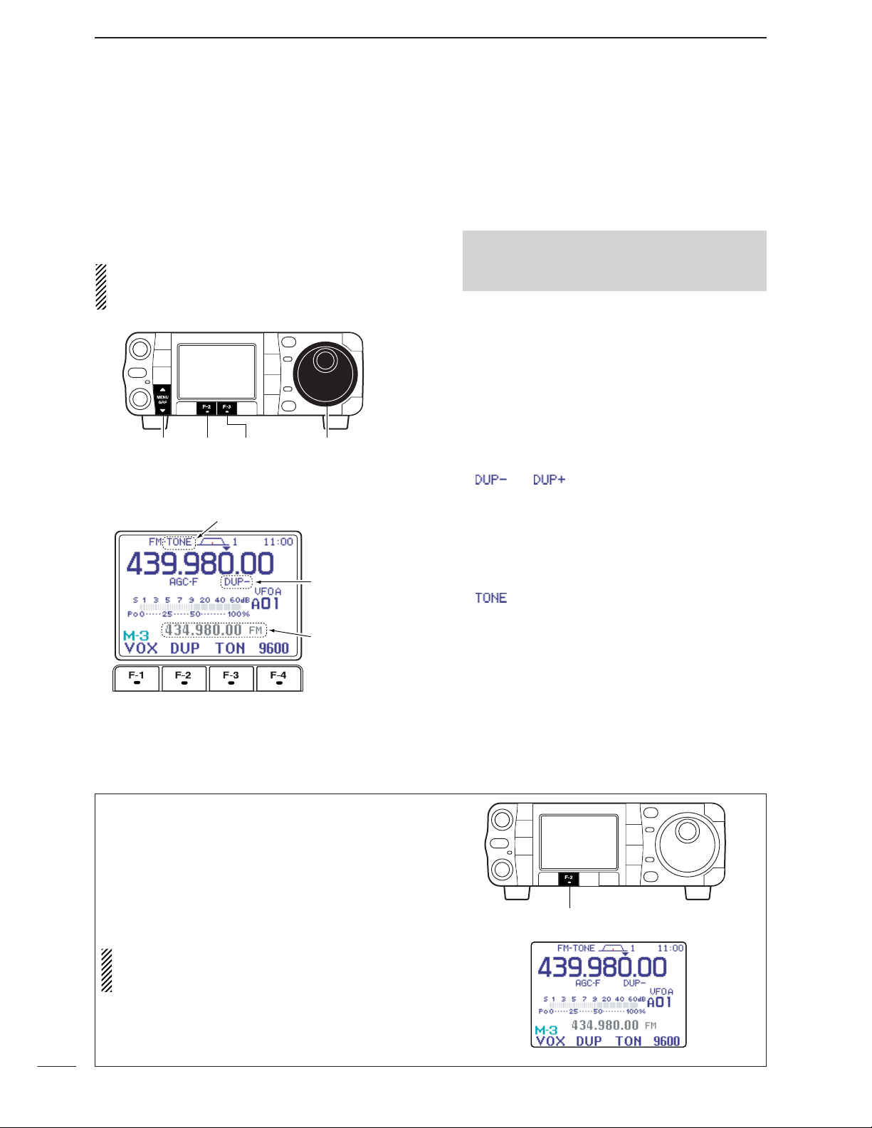
63
4
RECEIVE AND TRANSMIT
■ Repeater operation
A repeater amplifies received signals and retransmits
them at a different frequency. When using a repeater,
the transmit frequency is shifted from the receive frequency by an offset frequency. A repeater can be accessed using split frequency operation with the shift
frequency set to the repeater’s offset frequency.
For accessing a repeater which requires a repeater
tone, set the repeater tone frequency in the FM tone
set mode as described on the next page.
• To set the transceiver for repeater operation, follow
the steps q to e to select VFO mode, desired band,
FM mode.
q Push [F-4
V/M
] to select VFO mode.
w Push [
Y
(
BAND
)]/[
Z
(
BAND
)] to select the desired
band or push a band key on the HM-151.
e Push [MODE] momentarily or push and hold for 1
sec. to select FM mode.
•After FM, WFM or AM mode is selected, push [MODE]
for 1 sec. to select from FM, WFM and AM modes.
r Rotate [DIAL] to set the receive frequency (repeater
output frequency).
t Select
M
-
3
.
y Push [F-2
DUP
] once or twice to set the offset di-
rection.
• “ ” or “ ” appears.
•The default repeater offsets are the standard values of
0.1000 MHz for HF, 0.500 MHz for 50MHz, 0.600 MHz
for 144 MHz, and 5.000 MHz for 430 MHz. The offset
can be adjusted in set mode. (p. 132)
•The transmit frequency can be monitored while pushing
[F-4
XFC
] in the
M
-
1
display
.
u Push [F-3
TON
] to turn the repeater tone ON.
• “”appears.
•The tone frequency can be set in the FM tone set mode
as described on the next page.
i Communicate in the usual manner.
•Push and hold [PTT] to transmit; release [PTT] to re-
ceive.
•Push and hold [MENU/GRP] for 1 sec. once or twice to
select the menu group M.
•Push [MENU/GRP] momentarily one or more times to
select the menu
M
-
2
.
Shifted frequency
and mode appear.
“DUP–” or “DUP+”
appears.
“TONE” appears.
[DIAL][MENU/GRP] [F-2] [F-3]
This function allows you to set repeater operation by
pushing one key.
➥ To set the transceiver for repeater operation using
the one-touch repeater function, follow the steps q
to t as above, then push and hold [F-2
DUP
] for
1sec.
•Push [F-2
DUP
] for 1 sec. again to exit the repeater op-
erating condition
.
Set the offset shift direction and frequency in advance (p. 132) as well as the tone frequency (see
p. 64).
[F-2]
D One-touch repeater function
Page 73

64
4
RECEIVE AND TRANSMIT
4
Some repeaters require subaudible tones to be accessed. Subaudible tones are superimposed over
your normal signal and must be set in advance. The
transceiver has 50 tones from 67.0 Hz to 254.1 Hz.
Each memory channel can store a different subaudible tone frequency.
q Select
M
-
3
.
w Push [F-3
TON
] once or twice to turn the tone en-
coder ON.
•“TONE” appears.
e Push [F-3
TON
] for 1 sec. to enter the FM tone set
mode.
•The selected tone frequency appears.
•Other tone function can be set by pushing [F-1
TON
].
r Rotate [DIAL] to set the desired subaudible tone
frequency.
•See table at right for available tone frequencies.
t Push [Z(
MENU/GRP
)] to exit the FM tone set mode.
Store repeater tone frequencies and ON/OFF settings
in memory channels for easy recall. The transceiver’s
repeater tone frequency is set to 88.5 Hz by default.
This can be changed if desired.
• Available tone squelch frequencies
(Unit: Hz)
[DIAL][MENU/GRP] [F-3][F-1]
CONVENIENT
•Push and hold [MENU/GRP] for 1 sec. once or twice
to select the menu group M.
•Push [MENU/GRP] momentarily one or more times to
select the menu
M
-
3
.
D Repeater tone frequency
67.0
69.3
71.9
74.4
77.0
79.7
82.5
085.4
088.5
091.5
094.8
097.4
100.0
103.5
107.2
110.9
114.8
118.8
123.0
127.3
131.8
136.5
141.3
146.2
151.4
156.7
159.8
162.2
165.5
167.9
171.3
173.8
177.3
179.9
183.5
186.2
189.9
192.8
196.6
199.5
203.5
206.5
210.7
218.1
225.7
229.1
233.6
241.8
250.3
254.1
Page 74

D Auto repeater function
65
4
RECEIVE AND TRANSMIT
You may be able to receive the other party’s transmit
signal directly (called ‘listening on the repeater input’)
without having to go through a repeater.
Transmit frequency monitor check (XFC) allows you
to check this.
q Select
M
-
1
.
w While receiving, push and hold [F-4
XFC
] to see if
you can receive the other party’s transmit signal directly.
•While holding [F-4
XFC
], the offset direction and frequency are displayed above the multi-function key indicator.
SPCH
/LOCK
TUNER
/CALL
XFC
V/M
F-1
F-2
FIL
MODE
GENE
MW
123
456
789
.
0
CE
F-INP
ENT
1.8 3.5 7
10 14 18
21 24 28
50 144 430
HM-151
XFC
•Push and hold [MENU/GRP] for 1 sec. once or twice
to select the menu group M.
•Push [MENU/GRP] momentarily one or more times to
select the menu
M
-
1
.
[MENU/GRP] [F-4]
D Transmit frequency monitor check
This function automatically activates the repeater settings (DUP– or DUP+ and/or tone encoder ON/OFF)
when the operating frequency falls within the general
repeater output frequency range and deactivates
them when outside of the range.
Set the auto repeater function ON-1 (auto duplex setting) or ON-2 (auto duplex setting and activating tone
encoder) in the miscellaneous (others) set mode in
advance (p. 133). When ON-1 or ON-2 are turned on,
repeater settings are automatically activated according to the table below right.
ON-1 sets the duplex setting and ON-2 sets the duplex setting and tone encoder automatically.
q Push [AF(
SET
)] momentarily to enter the set mode
menu.
w Push [F-4
OTH
] to enter the miscellaneous (oth-
ers) set mode.
e Push [F-1≤] or [F-2≥] to select “
Auto Re-
peater
.”
r Rotate [DIAL] to select the desired auto repeater
condition from ON-1, ON-2 and OFF.
•Push[F-4
DEF
] for 1 sec. to return to default setting.
t Push [Z(
MENU/GRP
)] twice to return to the normal
operating mode.
• Frequency range and offset direction
[DIAL][MENU/GRP]
[AF]
[F-1] [F-2] [F-4]
FREQUENCY RANGE DUPLEX DIRECTION
145.200–145.495 MHz minus duplex
146.610–146.995 MHz minus duplex
147.000–147.395 MHz plus duplex
442.000–444.995 MHz plus duplex
447.000–449.995 MHz minus duplex
Page 75

66
4
RECEIVE AND TRANSMIT
4
D Storing a non standard repeater
q Turn the auto repeater function OFF in the miscel-
laneous (others) set mode. (p. 133)
w Push [MODE] to select FM mode.
e Select
M
-
2
.
r Push [F-4
V/M
] to select VFO mode.
t Select
M
-
1
, then push [F-2
A/B
] to select VFO A.
y Rotate [DIAL] to set the receive frequency (re-
peater output frequency).
u Push [F-2
A/B
] to select VFO B.
i Rotate [DIAL] to set the transmit frequency (re-
peater input frequency).
o Push [F-2
A/B
] to select VFO A.
!0 Push [F-1
SPL
] to turn the split function ON.
• “ ” appears.
!1 Select
M
-
3
, then push [F-3
TON
] to turn on the
previously set tone encoder ON. (p. 64)
!2 Rotate [M-ch] to select the desired memory chan-
nel.
• “ ” appears when the blank channel is selected.
!3 Select
M
-
2
, then push [F-2MW] for 1 sec. to store
the contents in the selected memory channel.
Rotate
Push
push
TON
SPL
push
MW
Set the frequency.
Selected M2, then
Selected M3, then
Set the frequency.
Appears
Appears
Select
Select
Select
•Push and hold [MENU/GRP] for 1 sec. once or twice
to select the menu group M.
•Push [MENU/GRP] momentarily one or more times to
select the menu
M
-
2
.
[DIAL][MENU/GRP]
[F-1]
[F-2] [F-3] [F-4]
Page 76
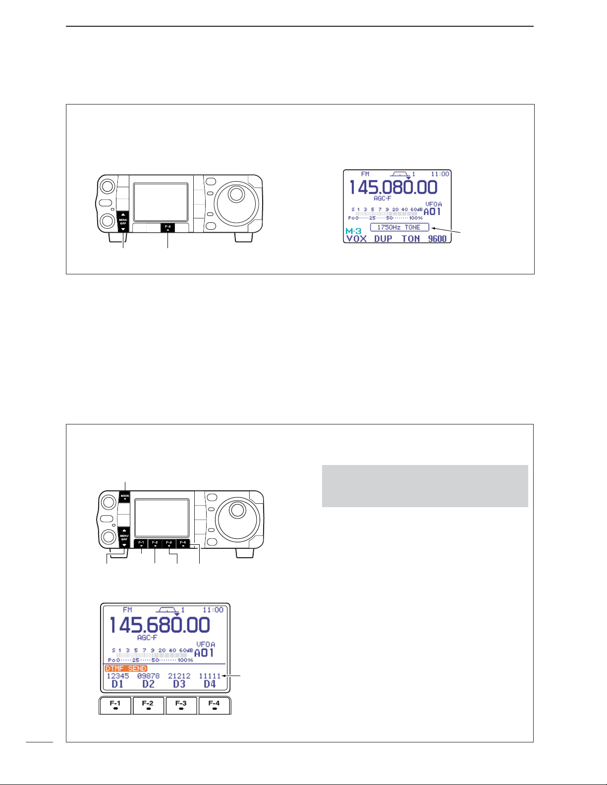
67
4
RECEIVE AND TRANSMIT
A 1750 Hz tone is required to access most European
repeaters.
➥ While pushing [PTT], push [F-3
TON
] in the M-3
menu during repeater operation. (pgs. 63, 66)
Popup indication
appears.
[MENU/GRP] [F-3]
■ 1750 Hz tone burst
To transmit a DTMF code using a DTMF send menu,
program the desired code in advance as described on
next page.
• Transmitting
q Select FM mode with [MODE].
w Select
S
-
1
.
e Push [F-2
DTM
] to enter the DTMF send menu.
•If the DTMF root menu appears, push [F-1
SND
]. The
DTMF starting menu can be changed in the miscellaneous (others) set mode (see p.136).
r Push [F-1D1] — [F-4D4] to transmit the DTMF
code.
•“D1”– “D4” are highlighted while transmitting.
•Set the DTMF speed from 100–500 msec. (100 msec.
steps). See next page for DTMF set mode.
t Push [Z(
MENU/GRP
)] twice to exit DTMF send
menu and return to the normal FM mode display.
•Push and hold [MENU/GRP] for 1 sec. once or twice
to select the menu group S.
•Push [MENU/GRP] momentarily one or more times to
select the menu
S
-
1
.
• DTMF send menu
DTMF code
sequence
[MODE]
[MENU/GRP]
[F-1]
[F-2] [F-3] [F-4]
D DTMF send menu
■ DTMF memory encoder
DTMF tones are used for autopatching, controlling
other equipment, etc. The transceiver has 4 DTMF
memory channels (D1–D4) for storage of often-used
DTMF codes sequence of up to 24 digits.
Page 77

68
4
RECEIVE AND TRANSMIT
4
D
Programming a DTMF code
q Push [MODE] to select FM mode.
w Select
S
-
1
.
e Push [F-2
DTM
] then [Z(
MENU
/
GRP
)] to select the
DTMF root menu.
•If the DTMF root menu appears, skip pushing
[Z(
MENU
/
GRP
)]. The DTMF starting menu can be
changed in the miscellaneous (others) set mode. (see
p.136)
r Push [F-2
EDT
] to enter the DTMF edit menu.
t Push [F-1D1] — [F-4D4] to select the desired
DTMF memory channel.
y Select the desired code by rotating [DIAL].
•Push[F-1Å] or [F-2Ç] for cursor movement.
•Push[F-3
DEL
] to delete the selected code.
u Repeat steps t and y until the desired contents
are input.
i Push [Z(
MENU/GRP
)] to return to memory channel
selection mode, then select the next memory channel and repeat steps t and u for code input, if desired.
o Push [Z(
MENU/GRP
)] twice to exit the keyer edit
mode.
DTMF memory channel select
Selected
code
[MENU/GRP]
[F-1]
[F-2] [F-3] [F-4] [DIAL]
•Push and hold [MENU/GRP] for 1 sec. once or twice
to select the menu group S.
•Push [MENU/GRP] momentarily one or more times to
select the menu
S
-
1
.
The rate at which DTMF memories send individual
DTMF characters can be set to accommodate operating needs.
q Select the DTMF root menu as described above.
w Push [F-4
SET
] to enter the DTMF set mode.
e Rotate [DIAL] to set the desired DTMF speed.
•Four rates are available: “100 ms” is the fastest; “500
ms” is slowest.
•Push [F-4
DEF
] for 1 sec. to select the default rate.
r Push [Z(
MENU/GRP
)] twice to exit the DTMF set
mode and return to the normal FM mode display.
D DTMF speed
Page 78

69
4
RECEIVE AND TRANSMIT
■ TV channel operation
q Push and hold [AF(
SET
)] for 1 sec. to turn the TV
mode ON.
•Push and hold [AF(
SET
)] for 1 sec again to exit the TV
mode.
w Rotate [M-ch] (inner) control to select the desired
TV channel.
•[Y(
BAND
)]/[Z(
BAND
)] keys also select the TV channel.
•The popup indicator appears and shows the selected
channel number. (The popup indicator can be turned
OFF in the display set mode. p.128)
e Push [P.AMP/ATT] momentarily to turn the preamp
ON and OFF; push and hold for 1 sec. to turn the
12 dB attenuator ON.
•The popup indicator, “ ” or “ ,” appears
when the preamp is ON or attenuator is ON, respectively. (The popup inidicator can be turned OFF in the
display set mode. p. 128)
•Each channel can store the preamp or attenuator
ON/OFF conditions independently.
• Only one of these functions can be activated at a time.
r Rotate [AF] to set a suitable audio level.
WARNING! NEVER watch a TV program while
driving a vehicle. Safe driving requires your full attention–anything less may result in an accident.
D Convenient functions for receive
• Preamp and attenuator (p. 74)
➥ Push [P.AMP/ATT] momentarily to turn the pre-
amp ON or OFF.
• “ ” appears when the preamp is set to ON.
➥ Push [P.AMP/ATT] for 1 sec. to set the attenua-
tor ON.
•Push [P.AMP/ATT] momentarily to turn the attenuator
OFF.
• “ ” appears when the attenuator is set to ON.
[P.AMP/ATT][AF]
[Y]
[Z]
[M-ch]
Page 79

70
4
RECEIVE AND TRANSMIT
4
Unwanted channels can be skipped for rapid selection, etc.
q Select the TV mode.
•Push and hold [AF(
SET
)] for 1 sec.
w Push [AF(
SET
)] momentarily to turn the blue-back-
ground display ON.
e Rotate [M-ch] (inner) control to select the desired
TV channel to be a skipped.
•[Y(
BAND
)]/[Z(
BAND
)] keys also select the TV channel.
r Push [F-1
SKP
] to turn the channel skip setting
ON.
• “ ” appears and [RX] indicator turns OFF.
•Push [F-1
SKP
] again to cancel the skip setting.
t Repeat steps e, r to set the other channels, if de-
sired.
y Push [AF(
SET
)] momentarily to turn the blue-back-
ground display OFF.
All channels (including skip channels) can be se-
lected on the blue-background display.
Push [F-1 SKP]
Appears
[Y]
[Z]
[AF] [RX] indicator
[F-1][M-ch]
D
Skip channel setting
Page 80

71
4
RECEIVE AND TRANSMIT
q Select the TV mode.
•Push and hold [AF(
SET
)] for 1 sec.
w Push [AF(
SET
)] momentarily to turn the blue-back-
ground display ON.
e Rotate [M-ch] (inner) control to select the desired
TV channel.
•[Y(
BAND
)]/[Z(
BAND
)] keys also select the TV channel.
r Push [F-2
ADJ
] to enter the channel frequency set
mode.
•The selected channel frequency appears and [RX] in-
dicator blinks.
•Push [TS] to toggle the tuning step from 1 kHz and 250
kHz.
•Push [Z(
MENU/GRP
)] to exit the channel frequency set
mode.
t Rotate [DIAL] to adjust the channel frequency.
•“
Push [SET]
” blinks.
•Push[Z(
MENU/GRP
)] to cancel the setting.
y Push [F-3
SET
] to set the channel frequency.
•Push [F-4
DEF
] for 1 sec. to return to the default fre-
quency.
u Push [Z(
MENU/GRP
)] to exit the channel frequency
set mode.
•The channel frequency disappears and [RX] indicator
stops blinking.
i Repeat steps e to u to set the another channels,
if desired.
o Push [AF(
SET
)] momentarily to turn the blue-back-
ground display OFF.
Push
Rotate
ADJ
Push
SET
[Y]
[Z]
[DIAL]
[AF] [TS][RX] indicator
[MENU/GRP] [F-4][F-2]
[M-ch]
[F-3]
D
Channel frequency adjustment
Page 81

5
72
FUNCTIONS FOR RECEIVE
■ Simple band scope
This DSP-based simple band scope allows you to display conditions on the selected band, as well as relative strength of signals. The IC-7000 has two modes
for the spectrum indication—one is fix mode, and another one is center mode.
➥ Select
G
-
1
(Scope).
NOTE: The IC-7000’s simple band scope can monitor the displayed frequency during sweeping. Both
of the receving and sweeping functions use the
same receive circuit which switch alternatively especially at high speed. Thus this switching sound
during may be irritating to listen to. If so, set the desired monitoring sound, “
FAST Sweep Sound
,”
or change the fast sweep setting, “
FAST
Sweep
,” in the scope set mode (p. 73).
•Push and hold [MENU/GRP] for 1 sec. once or twice
to select the menu group G(Graphic).
•Push [MENU/GRP] momentarily one or more times to
select the menu
G
-
1
(Scope).
D Fix mode
Displays signals within the specified frequency range.
The selected band conditions can be observed at a
glance when using this mode.
NOTE: If there is a lot of signal noise, turn the preamp OFF and the attenuator ON (p. 74) to reduce
the input level and improve the readability of the
scope.
q Set a mode and frequency.
w Select
G
-
1
(Scope).
e Push [F-3
FIX
] momentarily to select the fix
mode.
• “O” and readout frequency indicator appear when the
fix mode is selected.
r Push [F-4
SPD
] momentarily to select the sweep
speed.
• “≈” or “≈≈” appears when Slow speed or Fast speed is
selected, respectively.
t Push [F-1
SPN
] one or more times to select the
desired steps.
•±10, 25, 50, 100 and 250 kHz are available.
•Push and hold [F-1
SPN
] for 1 sec. to select the ±10
kHz step.
• “<” or “>” indicates when the displayed frequency is out
of range. The scope center position can be set to the
displayed frequency by pushing and holding [F-3
FIX
] for 1 sec.
•The simple band scope operates in the peak level hold
mode. Peak levels are displayed in the background of
the current spectrum in a different color until the receive
frequency changes. This can be cleared by pushing
and holding [F-2
HLD
] for 1 sec., or deactivated in the
scope set mode. (p. 73)
y Push [F-2
HLD
] to freeze the current spectrum dis-
play.
•“H” appears while the function is in use.
•Push and hold [MENU/GRP] for 1 sec. once or twice
to select the menu group G(Graphic).
•Push [MENU/GRP] momentarily one or more times to
select the menu
G
-
1
(Scope).
[MENU/GRP]
[F-1]
[F-2] [F-3] [F-4]
Quick entry
➥ Push [Y(
BAND
)] for 1 sec. to turn the simple
band scope ON and OFF.
•Push [Z(
MENU/GRP
)] also to turn OFF.
[Y]
4
5
[MENU/GRP]
Page 82

73
5
FUNCTIONS FOR RECEIVE
D Center mode
Displays signals around the displayed frequency
within the selected span. The set frequency is always
displayed at the center of the screen.
q Set a mode and frequency.
w Select
G
-
1
(Scope).
e Push [F-3
FIX
] momentarily to select the center
mode.
•“=” appears when the center mode is selected.
r Push [F-4
SPD
] momentarily to select the sweep
speed.
• “≈” or “≈≈” appears when Slow speed or Fast speed is
selected, respectively.
t Push [F-1
SPN
] one or more times to select the
desired steps.
•±10, 25, 50, 100 and 250 kHz are available.
•Push and hold [F-1
SPN
] for 1 sec. to select the ±10
kHz step.
•The simple band scope operates in the peak level hold
mode. Peak levels are displayed in the background of
the current spectrum in a different color until the receive
frequency changes. This can be cleared by pushing
and holding [F-2
HLD
] for 1 sec., or deactivated in the
scope set mode. (below)
y Push [F-2
HLD
] to freeze the current spectrum dis-
play and range.
•“H ” and readout frequency indicator appear while the
function is in use.
NOTE: If there is a lot of signal noise, turn the preamp OFF and the attenuator ON (p. 74) to reduce
the input level and improve the readability of the
scope.
[MENU/GRP]
[F-1]
[F-2] [F-3] [F-4]
•Push and hold [MENU/GRP] for 1 sec. once or twice
to select the menu group G(Graphic).
•Push [MENU/GRP] momentarily one or more times to
select the menu
G
-
1
(Scope).
D Scope set mode
This set mode is used to set the peak hold function
and scope size setting.
q Select
G
-
1
(Scope).
w Push and hold [F-4
SPD
] for 1 sec. to enter the
scope set mode.
e Push [F-1≤] or [F-2≥] to select the desired set
item.
r Set the desired condition using [DIAL].
•Push [F-4
DEF
] for 1 sec. to select a default condition.
t Push [Z(
MENU/GRP
)] to exit from set mode.
[MENU/GRP] [F-1] [F-2] [F-4] [DIAL]
•Push and hold [MENU/GRP] for 1 sec. once or twice
to select the menu group G(Graphic).
•Push [MENU/GRP] momentarily one or more times to
select the menu
G
-
1
(Scope).
Page 83

74
5
FUNCTIONS FOR RECEIVE
5
■ Preamp and attenuator
The preamp amplifies received signals in the receiver
input (front end) circuit to improve the S/N ratio and
sensitivity. Turn this function ON when receiving weak
signals.
The attenuator prevents a strong undesired signal
near the desired frequency or near your location,
such as from a broadcast station, from causing distortion or spurious signals.
Push [P.AMP/ATT] momentarily to turn the preamp
ON and OFF; push and hold for 1 sec. to turn the attenuator ON.
•“ ” appears when the preamp is ON; “ ” appears when the 12 dB attenuator is ON.
• Only one of these functions can be activated at a time.
momentarily
momentarily 1 sec.
[P.AMP/ATT]
“ ” or “ ” appears.
Scope set mode (Continued)
1
Max Hold
This item turns the peak level holding function ON
and OFF.
ON
Peak hold is turned ON.
(default)
OFF
Peak hold is turned OFF.
2
Scope Size
This item turns the scope size setting normal and
wide.
Normal
Normal size is selected.
(default)
Wide
Wide size is selected.
3
FAST Sweep
This item selects the sweep speed setting.
Continuous
Push [F-4
SPD
] momentar-
ily to toggle the sweep
speed Fast and Slow continuously. (default)
1 Sweep
Sweep speed changes Slow
to Fast just for one sweep
every pushing [F-4
SPD
]
momentarily.
4
FAST Sweep Sound
This item sets the monitoring sound level for fast
sweeping.
-10dB
:
Monitoring sound is set 10 dB smaller than
normal sound. (default)
0dB
: Same as normal sound.
OFF
: No sound comes out while fast sweeping
.
Page 84

■ RIT function
The RIT (Receive Incremental Tuning) function compensates for communicating stations off-frequency.
The function shifts the receive frequency up to ±9.999
kHz in 1 Hz steps (10 Hz steps when cancelling the 1
Hz step readout) without moving the transmit frequency.
q Push [PBT/M-ch/RIT] momentarily to select the M-
ch/RIT function, if the twin PBT is selected.
•[PBT/M-ch/RIT] indicator (Green) goes out.
w Push [PBT/M-ch/RIT] for 1 sec. to enter the
RIT/∂TX mode.
e Push [F-1
RIT
] to turn the RIT function ON.
•“ ” indicator and the frequency shift appear and
[PBT/M-ch/RIT] indicator lights orange when the func-
tion is ON.
r Rotate [RIT] (outer) control to compensate for off-
frequency stations.
• The transmit frequency is not shifted.
t To reset the RIT frequency, push [F-3
CLR
] for 1
sec.
•Push [F-3
CLR
] momentarily to reset the RIT fre-
quency when “
Quick RIT/∂TX Clear
” in the
miscellaneous (others) set mode is ON. (p. 135)
y To cancel the RIT function, push [F-1
RIT
] mo-
mentarily again.
• “ ” indicator disappears.
u Push [Z(
MENU/GRP
)] to exit the RIT/∂TX mode.
When RIT and ∂TX are ON at the same time, the
[RIT] (outer) control shifts both the transmit and re-
ceive frequencies from the displayed frequency at
the same time.
Push
Push
Rotate
Push for 1sec.
Appear
Reset to
“0.00k”
[MENU/GRP] [F-1] [F-3]
[PBT/M-ch/RIT] indicator
[PBT/M-ch/RIT] switch
[RIT] (outer)
75
5
FUNCTIONS FOR RECEIVE
• Calculate function
The shift frequency of the RIT (or ∂TX) function can
be added/subtracted to the displayed frequency.
While displaying the RIT (and/or ∂TX) shift frequency, push and hold [F-1
RIT
] (or [F-2
∂TX
]) for
1 sec.
• Practical example
When you find a DX station on 21.025 MHz/CW and
the station is picking up stations transmitting slightly
up from 21.025 MHz.
q Push [F-1
RIT
] and [F-2
∂TX
] to turn both the
RIT and ∂TX functions ON.
w Rotate [RIT] (outer) to find the DX station’s re-
ceive frequency.
e When you find the DX station’s receive frequency,
push [F-1
RIT
] to turn the RIT function OFF.
•Now you can transmit the DX station’s receive frequency and receive on the DX station’s transmit frequency (21.025 MHz).
r Start transmitting when the station stands by for
new callers.
Push and hold
Page 85

D Setting the AGC time constant
76
5
FUNCTIONS FOR RECEIVE
5
■ AGC function
The AGC (auto gain control) controls receiver gain to
produce a constant audio output level even when the
received signal strength is varied by fading, etc.
The transceiver has 3 AGC characteristics (time constant; fast, mid, slow) for non-FM/WFM mode.
The FM/WFM modes AGC time constant is fixed as
‘FAST’ (0.1 sec.) and AGC time constant cannot be
selected.
q Select non-FM/WFM mode with [MODE].
w Select
M
-
3
.
e Push [F-3
AGC
] several times to select AGC fast,
AGC medium (MID) AGC slow or AGC OFF.
• “ ,” “ ,” “ ” or “ ” appears when
AGC fast, AGC medium (MID), AGC slow or AGC OFF
is selected, respectively.
“ ” (OFF)
appears when AGC time constant
OFF is set with one of FAST, MID, SLOW setting
in AGC set mode.
[MENU/GRP] [F-3]
•Push and hold [MENU/GRP] for 1 sec. once or twice
to select the menu group M.
•Push [MENU/GRP] momentarily one or more times to
select the menu
M
-
3
.
D AGC time constant selection
q Select the desired mode other than FM/WFM
modes.
w Select
M
-
3
.
e Push [F-3
AGC
] for 1 sec. to enter the AGC set
mode.
r Push one of [F-2
FAST
], [F-3
MID
], [F-4
SLOW
]
to select the desired AGC time constant.
t Rotate [DIAL] to set the desired time constant.
•AGC time constants can be selected between 0.1 to
8.0 sec. (depends on mode) or turned OFF.
•Push and hold [F-2
FAST
], [F-3
MID
] or [F-4
SLOW
]
for 1 sec. to select a default value each for fast, mid.
and slow, respectively.
y Select another mode other than FM/WFM. Repeat
steps r and t, if desired.
•See table to the right for available tone frequencies.
u Push [Z(
MENU/GRP
)] to exit the AGC set mode.
• Selectable AGC time constant (unit: sec.)
[MENU/GRP] [DIAL][F-3] [F-4][F-2]
•Push and hold [MENU/GRP] for 1 sec. once or twice
to select the menu group M.
•Push [MENU/GRP] momentarily one or more times to
select the menu
M
-
3
.
Mode Default Selectable AGC time constant
0.3 (FAST)
OFF, 0.1, 0.2, 0.3, 0.5, 0.8, 1.2,
SSB 2.0 (MID)
1.6, 2.0, 2.5, 3.0, 4.0, 5.0, 6.0
6.0 (SLOW)
0.1 (FAST)
OFF, 0.1, 0.2, 0.3, 0.5, 0.8, 1.2,
CW 0.5 (MID)
1.6, 2.0, 2.5, 3.0, 4.0, 5.0, 6.0
1.2 (SLOW)
0.1 (FAST)
OFF, 0.1, 0.2, 0.3, 0.5, 0.8, 1.2,
RTTY 0.5 (MID)
1.6, 2.0, 2.5, 3.0, 4.0, 5.0, 6.0
1.2 (SLOW)
3.0 (FAST)
OFF, 0.3, 0.5, 0.8, 1.2, 1.6, 2.0,
AM 5.0 (MID)
2.5, 3.0, 4.0, 5.0, 6.0, 7.0, 8.0
7.0 (SLOW)
FM/WFM
0.1 (FAST) Fixed
Page 86

D IF filter selection
77
5
FUNCTIONS FOR RECEIVE
■ IF filter selection
The transceiver has 3 passband width IF filters for
each mode.
For SSB and CW modes, the passband width can be
set from 50 to 3600 Hz in 50 or 100 Hz steps. A total of
41 passband widths are available.
For RTTY mode, the passband width can be set from
50 to 2700 Hz in 50 or 100 Hz steps. A total of 32
passband widths are available.
For AM mode, the passband width can be set from 200
Hz to 10 kHz in 200 Hz steps. A total of 50 passband
widths are available.
For FM mode, the passband width is fixed and 3 passband widths are available.
For WFM mode, the passband width is fixed at 280
kHz.
The filter selection is automatically memorized in
each mode.
The PBT shift frequencies are automatically memorized in each filter.
q Select the desired mode.
w Select
M
-
1
.
e Push [F-3
FIL
] momentarily several times to se-
lect the IF filter 1, 2 or 3.
•The selected filter number is displayed in the LCD.
•The filter setting window appears and shows the selected passband width and shift frequency. (The filter
setting window can be turned OFF in the display set
mode. (p. 127)
The IF filter for WFM mode is fixed and cannot be
changed.
SPCH
/LOCK
TUNER
/CALL
XFC
V/M
F-1
F-2
FIL
MODE
GENE
MW
123
456
789
.
0
CE
F-INP
ENT
1.8 3.5 7
10 14 18
21 24 28
50 144 430
HM-151
FIL
Passband
width
Selected IF filter
Shift
frequency
Popup indicator appears
•Push and hold [MENU/GRP] for 1 sec. once or twice
to select the menu group M.
•Push [MENU/GRP] momentarily one or more times to
select the menu
M
-
1
.
[MENU/GRP] [F-3]
Page 87

78
5
FUNCTIONS FOR RECEIVE
5
q Select SSB, CW, RTTY or AM mode.
•Passband widths for FM and WFM modes are fixed
and cannot be set.
w Select
M
-
1
.
e Push [F-3
FIL
] for 1 sec. to enter filter set mode.
r Push [F-3
FIL
] several times to select the desired
IF filter.
t While pushing [F-1BW], rotate [DIAL] to set the
desired passband width.
•The passband width can be set within the range as
shown in the table to the right.
•Push [F-2
DEF
] for 1 sec. to select the default value.
y Repeat steps r to t if desired.
u Push [Z(
MENU/GRP
)] to exit the filter set mode.
The PBT shift frequencies are cleared when the
passband width is changed.
This filter set mode screen graphically displays the
PBT shift frequencies.
*: When the IF filter is selected FIL2 or FIL3 in the FM
mode operation, the Tx IF filter’s passband width is
fixed narrow selection (2.5 kHz).
FIL1
Mode Filter Default Range (Steps)
3.0 kHz
1.8 kHz
2.4 kHz
1.2 kHz
250 Hz
7.0 kHz
500 Hz
2.4 kHz
250 Hz
500 Hz
9.0 kHz
3.0 kHz
6.0 kHz
10 kHz Fixed
15 kHz
50–500 Hz (50 Hz)/
600–3.6 kHz (100 Hz)
50–500 Hz (50 Hz)/
600–3.6 kHz (100 Hz)
50–500 Hz (50 Hz)/
600–2.7 kHz (100 Hz)
200 Hz–10.0 kHz
(200 Hz)
FIL2
SSB
RTTY
AM
FM*
WFM
CW
FIL3
FIL1
FIL2
FIL3
FIL1
FIL2
FIL3
FIL1
FIL2
FIL3
FIL1
FIL2
280 kHz FixedFIL
FIL3
[MENU/GRP] [DIAL][F-2] [F-3][F-1]
•Push and hold [MENU/GRP] for 1 sec. once or twice
to select the menu group M.
•Push [MENU/GRP] momentarily one or more times to
select the menu
M
-
1
.
D FIlter passband width setting (SSB/CW/RTTY/AM only)
D IF fIlter shape (SSB/CW only)
The type of DSP filter shape for each SSB and CW
can be selected independently from soft and sharp.
q Select SSB or CW mode.
w Select
M
-
1
.
e Push [F-3
FIL
] for 1 sec. to enter filter set mode.
r Push [F-3
FIL
] several times to select the desired
IF filter.
t Push [F-4] to select the filter shape from “
SHARP
”
and “
SOFT
.”
y Push [Z(
MENU/GRP
)] to exit the filter set mode.
Specified selectivity (p. 150) is measured with this
parameter set to SHARP.
Push
[MENU/GRP] [F-3] [F-4]
•Push and hold [MENU/GRP] for 1 sec. once or twice
to select the menu group M.
•Push [MENU/GRP] momentarily one or more times to
select the menu
M
-
1
.
Passband
width
Shift
frequency
Selected IF filter
Page 88

79
5
FUNCTIONS FOR RECEIVE
General PBT (Passband Tuning) function electronically
narrows the IF passband width by shifting the IF frequency to slightly outside of the IF filter passband to
reject interference. This transceiver uses the DSP circuit for the PBT function. Moving both [PBT
/M-ch/RIT]
controls to the same position shifts the IF.
➥ Push [PBT/M-ch/RIT] momentarily to select the
twin PBT function, if the M-ch-RIT is selected.
•[PBT/M-ch/RIT] indicator (Green) lights.
• The passband settings window shows the passband
width and shift frequency graphically. (The passband
settings window can be turned OFF in the display set
mode. p. 127)
➥ When
M
-
1
is selected, push [F-3
FIL
] for 1 sec. to
enter the filter set mode. Current passband width
and shift frequency is displayed in the filter set
mode.
➥ To set the [PBT
/M-ch/RIT] controls to the center posi-
tions, push [PBT
/M-ch/RIT(
CLR
)] for 1 sec.
The limit of the variable range depends on the passband width and mode. The edge of the variable range
is half of the passband width, and PBT is adjustable in
100 (AM) or 25 Hz steps (other modes).
•[PBT] controls should normally be set to the center posi-
tions (PBT setting is cleared) when there is no interference.
•When PBT is used, the audio tone may be changed.
• Not available for FM or WFM modes.
•While rotating [PBT], noise may occur. This comes from
the DSP unit and does not indicate an equipment malfunction.
PBT OPERATION EXAMPLE
IF center frequency Interference Desired signal
Passband
Both controls at
center position
Cutting a lower
passband
Cutting both higher and
lower passbands
Interference Interference
Desired signal
Passband
■ Twin PBT operation
[PBT/M-ch/RIT(CLR)] switch/[PBT] (inner) control
[PBT/M-ch/RIT] indicator
[F-3]
[PBT] (outer) control
Dot indicator appears
when PBT is activate
Passband
width
Shift
frequency
[MENU/GRP]
Selected IF filter
Popup indicator appears
Page 89

80
5
FUNCTIONS FOR RECEIVE
5
D
Noise blanker set mode
■ Noise blanker
The noise blanker eliminates pulse-type noise such
as from car ignitions. The noise blanker is not available for WFM mode.
➥ Push [NB/ADJ] momentarily to toggle the noise
blanker ON and OFF.
• “ ” indicator appears when the NB function is ON.
When using the noise blanker, received signals
may be distorted if they are excessively strong or
the noise type is other than impulse. Nearby strong
signals can also cause the noise blanker created
distortion. Turn the noise blanker function OFF, or
adjust the noise blanker level to shallow position
(see below) in this case.
[NB/ADJ]
Appears
q Push and hold [NB/ADJ] for 1 sec. to enter the
noise blanker set mode.
w Push [F-1≤] or [F-2≥] to select the desired set
item.
e Rotate [DIAL] to adjust the desired condition.
•Push[F-4
DEF
] for 1 sec. to return to default value.
r Push [NB/ADJ] (or push [Z(
MENU/GRP
)]) to exit the
noise blanker set mode.
[MENU/GRP]
[NB/ADJ]
[F-1] [F-2]
[F-4] [DIAL]
1.
NB Level
This item adjusts the noise blanker level. The noise
blanker level can be adjusted from 0 to 100%.
50%
50% (default)
2.
NB Width
This item adjusts the noise blanker width. The noise
blanker width can be adjusted from 1 to 100.
50
50 (default)
Page 90
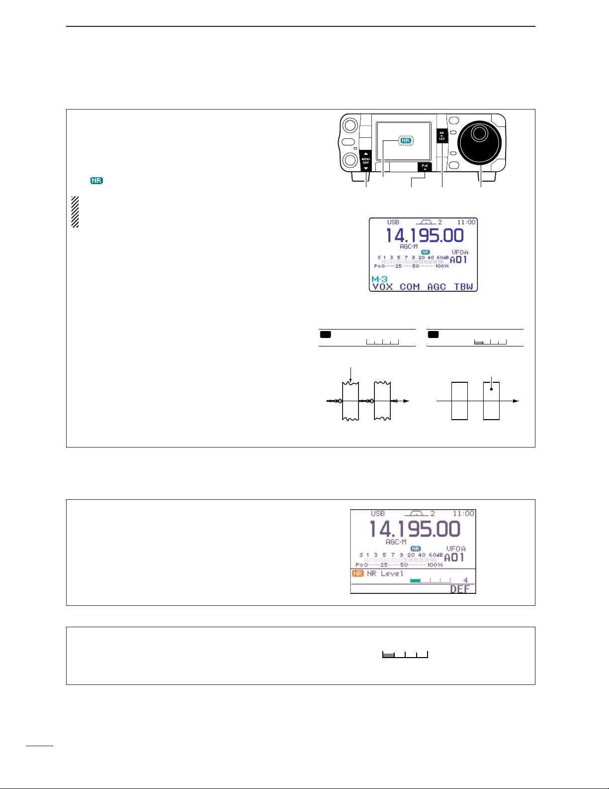
81
5
FUNCTIONS FOR RECEIVE
■ Noise reduction
The noise reduction function enhances desired signals in the presence of noise by using the DSP circuit. The amount of enhancement is adjustable.
➥ Push [NR/LEV] momentarily to toggle the noise re-
duction ON and OFF.
• “ ” indicator appears when the NR function is ON.
The noise reduction level can result in audio signal
masking. Set the noise reduction level for maximum readability as described below.
Noise reduction OFF Noise reduction activated
Desired
signal (CW)
Noise components
0
NR Level
NR
5
NR Level
NR
[MENU/GRP] [NR/LEV][F-4] [DIAL]
Appears
NR Level
This item adjusts the noise reduction level. The noise
reduction level can be adjusted from 0 to 15.
4
4 (default)
D
Noise reduction set mode
q Push [NR/LEV] for 1 sec. to enter the noise reduc-
tion level set mode.
w Rotate [DIAL] to adjust the noise reduction level.
• Set the noise reduction level 0 to 15.
•Push[F-4
DEF
] for 1 sec. to return to default level.
e Push [NR/LEV] (or push [Z(
MENU/GRP
)]) to exit the
noise reduction level set mode.
Page 91

82
5
FUNCTIONS FOR RECEIVE
5
D
Auto notch function
■ Notch function
This transceiver has auto and manual notch functions. The auto notch function automatically attenuates up to 3 beat tones, tuning signals, etc., even if
they are moving. The manual notch can be set to attenuate a frequency via the manual notch filter set
mode.
➥ While in SSB and AM modes, push [ANF/•REC] or
[MNF/ADJ] to toggle the notch function between
auto, manual and OFF.
• Both of the auto and manual notch functions can be activate at the same time.
➥ While in CW and RTTY modes, push [MNF/ADJ]
to toggle the manual notch function ON and OFF.
➥ While in FM and WFM modes, push [ANF/•REC]
to toggle the auto notch function ON and OFF.
• “ ” appears when auto notch function is in use.
• “ ” appears when manual notch function is in use.
•Manual notch filter settings are described on the next
page.
The auto notch can be used in SSB, AM, FM and
WFM modes.
➥ Push [ANF/•REC] momentarily to turn the auto-
matic notch function ON and OFF.
• “ ” appears when auto notch function is in use.
[ANF/•REC]
Appears
Unwanted frequency
is attenuated
Desired
signal (AF)
Desired
signal (AF)
Particular frequency
is attenuated
Auto notch OFF Auto notch ON
Page 92
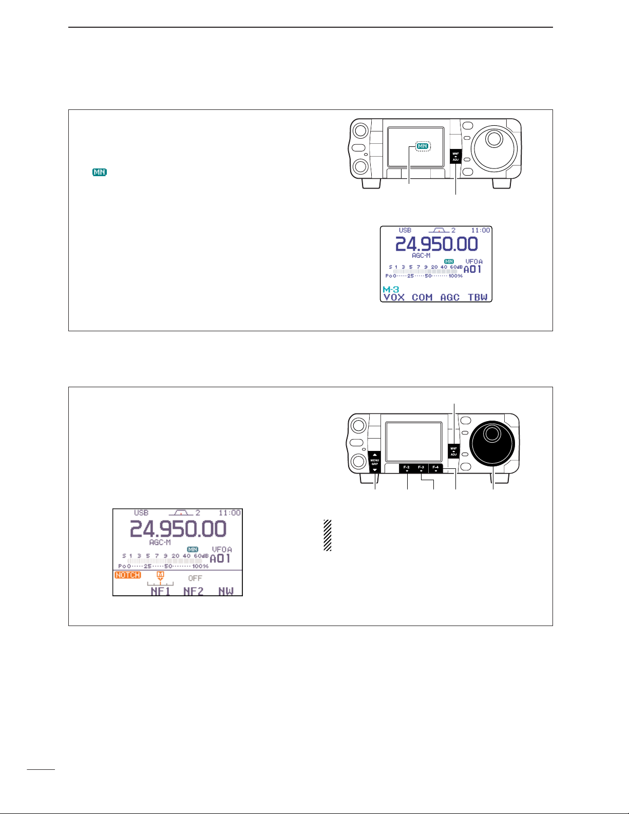
D
Manual notch function
83
5
FUNCTIONS FOR RECEIVE
q Push [MNF/ADJ] for 1 sec. to enter the manual
notch filter set mode.
w Push [F-2
NF1
] or [F-3
NF2
] to select the desired
filter ON and OFF.
e Rotate [DIAL] to adjust the selected filter fre-
quency.
•Push [F-4NW] to toggle the filter width from narrow,
middle and wide.
r Push [MNF/ADJ] (or push [Z(
MENU/GRP
)]) to exit
the manual notch filter set mode.
While adjusting the manual notch filter, noise may
be heard. This comes from the DSP unit and does
not indicate an equipment malfunction.
The manual notch function can be used in SSB, CW,
RTTY and AM modes.
➥ Push [MNF/ADJ] momentarily to turn the manual
notch function ON and OFF.
• “ ” appears when manual notch function is in use.
•Set the frequency for manual notch filtering via the
manual notch filter set mode. (shown below)
•Even when both of the manual notch filters, “
NF1
” and
“
NF2
,” are set to OFF in the manual notch filter set
mode, “
NF1
” is automatically turned ON if the manual
notch function is ON.
[MNF/ADJ]
Appears
D Manual notch filter set mode
[MNF/ADJ]
[MENU/GRP]
[F-2] [F-3]
[F-4] [DIAL]
Page 93

84
5
FUNCTIONS FOR RECEIVE
5
■ Meter peak hold function
The S-meter has a peak level holding function. The
peak level of the received signal strength is indicated
for 0.5 sec. (approx). This function can be deactivated
in the display set mode (“
Meter Peak Hold
” ;
see p. 127) if desired.
q Push [AF(
SET
)] momentarily to enter the set mode
menu.
w Push [F-2
DISP
] to enter the display set mode.
e Push [F-1≤] or [F-2≥] to select “
Meter Peak
Hold
.”
r Rotate [DIAL] to turn the meter peak hold setting
ON and OFF.
•Push [F-4
DEF
] for 1 sec. to return to default condition.
t Push [Z(
MENU/GRP
)] twice to return to normal op-
erating mode.
Initial reception of a
signal results in an
S-meter reading of
40 dB.
The highest indicated bar remains displayed for about 0.5
sec. even when the
signal strength decreases.
[EXAMPLE]:
S 7 60dB40209531
S 7 60dB40209531
[MENU/GRP] [F-2][F-1] [DIAL]
[AF]
■ Voice squelch control function
This function is useful when you don't want to hear
unmodulated signals. When the voice squelch control
function is activated, the transceiver checks received
signals for voice components.
If a receiver signal includes voice components, and
the tone of the voice components changes within 1
sec., squelch opens. If the received signal includes
no voice components or the tone of the voice components does not change within 1 sec., squelch closes.
q Select
S
-
1orS-2
.
w Push [F-4
VSC
] to turn the VSC (Voice Squelch
Control) function ON.
•“ ” appears when the function is activated.
•The VSC function is available for phone modes
(SSB, AM, FM, WFM).
•The VSC function can also be used for scanning
operation in AM, FM or WFM modes. (p. 114)
[MENU/GRP] [F-4]
Appears
•Push and hold [MENU/GRP] for 1 sec. once or twice
to select the menu group S.
•Push [MENU/GRP] momentarily one or more times to
select the menu
S
-
1orS-2
.
Page 94

6
85
FUNCTIONS FOR TRANSMIT
D Adjusting the VOX function
■ VOX function
The VOX (Voice-Operated Transmission) function
switches between transmit and receive with your
voice. This function provides an opportunity for
hands-free operation or to input log entries into your
computer, etc., while operating.
q Select a phone mode (SSB, AM, FM) with [MODE].
w Select
M
-
3
.
e Push [F-1
VOX
] to toggle the VOX function ON
and OFF.
•“ ” appears while the VOX is in use.
The VOX gain, ANTI-VOX and VOX delay can be set in
VOX set mode.
[MENU/GRP] [F-1]
Appears
•Push and hold [MENU/GRP] for 1 sec. once or twice
to select the menu group M.
•Push [MENU/GRP] momentarily one or more times to
select the menu
M
-
3
.
q Select a phone mode (SSB, AM, FM).
w Select
M
-
3
.
e Push [F-1
VOX
] for 1 sec. to enter the VOX set
mode.
r Select the VOX gain item using [F-1≤] or [F-2≥].
t While speaking into the microphone, rotate [DIAL]
to the point where the transceiver is continuously
transmitting.
y Adjust the VOX delay for a convenient interval be-
fore returning to receive.
- Select the VOX delay item using [F-1≤] or [F-2≥].
- Rotate [DIAL].
u If the receive audio from the speaker causes the
VOX circuit to switch to, adjust the anti VOX to the
point where it has no effect.
•Push and hold [MENU/GRP] for 1 sec. once or twice
to select the menu group M.
•Push [MENU/GRP] momentarily one or more times to
select the menu
M
-
3
.
[MENU/GRP] [F-2] [DIAL][F-1]
Page 95

D VOX set mode
86
6
FUNCTIONS FOR TRANSMIT
6
3.
VOX Delay
This item adjusts the VOX (Voice-activated Transmit)
delay time. The delay time can be adjusted from 0 to
2.0 sec. in 0.1 sec. steps.
•Push[F-4
DEF
] for 1 sec. to return to default delay time.
0. 2 s
0.2 sec. (default)
1.
VOX Gain
This item adjusts the VOX gain for the VOX (voice activated transmit) function.
This setting can be adjusted
from 0 to 100% in 1% steps.
•Push[F-4
DEF
] for 1 sec. to return to default gain.
50 %
50% (default)
2.
Anti-VOX
This item adjusts the ANTI-VOX gain for the VOX
(voice activated transmit) function.
This setting can be
adjusted from 0 to 100% in 1% steps.
•Push[F-4
DEF
] for 1 sec. to return to default gain.
50 %
50% (default)
■ Transmit filter width setting (SSB only)
The transmit filter width for SSB mode can be selected from wide, middle and narrow.
q Select an SSB mode (USB or LSB) with [MODE].
w Select
M
-
3
.
e Push and hold [F-4
TBW
] for 1 sec. once or twice
to select the desired transmit filter width from narrow, middle and wide.
•Push [F-4
TBW
] momentarily to indicate the selected
TX filter width.
•The transmit filter width window appears for showing
the selected TX filter width each time [F-4
TBW
].
•The following filters are specified as the default. Each
of the filter widths can be set in the quick set mode.
(pgs. 123, 124)
WIDE : 100 Hz to 2900 Hz
MID : 300 Hz to 2700 Hz
NAR : 500 Hz to 2500 Hz
•Push and hold [MENU/GRP] for 1 sec. once or twice
to select the menu group M.
•Push [MENU/GRP] momentarily one or more times to
select the menu
M
-
3
.
[MENU/GRP] [F-4]
Page 96

87
6
FUNCTIONS FOR TRANSMIT
D Full break-in operation
D Semi break-in operation
■ Break-in function
During semi break-in operation, the transceiver selects transmit when keying, then automatically returns
to receive after a pre-set time from when you stop
keying.
• Semi break-in operation
q Push [MODE] to select CW or CW-R mode.
w Select
M
-
3
.
e Push [F-1
BRK
] once or twice to turn the semi
break-in function ON.
• “”appears.
When using a paddle, set “
Key Speed
” in the
quick set mode to adjust the keying speed. (p. 124)
• Break-in delay setting
q Push [MODE] to select CW or CW-R mode.
w Select
M
-
3
.
e Push [F-1
BRK
] for 1 sec. to enter the break-in
delay time set mode.
r Rotate [DIAL] to set the break-in delay time (the
delay from transmit to receive).
[MENU/GRP] [F-1] [DIAL]
•Push and hold [MENU/GRP] for 1 sec. once or twice
to select the menu group M.
•Push [MENU/GRP] momentarily one or more times to
select the menu
M
-
3
.
During full break-in operation, the transceiver automatically switches to receive between keying dots
and dashes so that the operator can hear activity on
the channel when transmitting.
q Push [MODE] to select CW or CW-R mode.
w Select
M
-
3
.
e Push [F-1
BRK
] once or twice to turn the semi
break-in function ON.
• “”appears.
When using a paddle, set “
Key Speed
” in the
quick set mode to adjust the keying speed. (p. 124)
•Push and hold [MENU/GRP] for 1 sec. once or twice
to select the menu group M.
•Push [MENU/GRP] momentarily one or more times to
select the menu
M
-
3
.
[MENU/GRP] [F-1]
Appears
The break-in function is used in CW mode to automatically switch the transceiver between transmit and receive when keying. The IC-7000 is capable for full
break-in or semi break-in.
Appears
[MENU/GRP] [F-1]
Page 97

88
6
FUNCTIONS FOR TRANSMIT
6
■∂TX function
The ∂TX function shifts the transmit frequency up to
±9.999 kHz in 1 Hz steps (10 Hz steps when cancelling the 1 Hz step readout) without moving the receive frequency.
q Push [PBT/M-ch/RIT] momentarily to select the M-
ch/RIT function, if the twin PBT is selected.
•[PBT/M-ch/RIT] indicator (Green) goes out.
w Push [PBT/M-ch/RIT] for 1 sec. to enter the
RIT/∂TX mode.
e Push [F-2
∂TX
] to turn the ∂TX function ON.
•“ ” indicator and the frequency shift appear and
[PBT/M-ch/RIT] indicator lights orange when the func-
tion is ON.
r Rotate [RIT] (outer) control to shift the transmitter
frequency.
• The receive frequency is not shifted.
t To reset the ∂TX frequency, push [F-3
CLR
] for
1 sec.
•Push [F-3
CLR
] momentarily to reset the RIT fre-
quency when “
Quick RIT/∂TX Clear
” in the
miscellaneous (others) set mode is ON. (p. 135)
y To cancel the ∂TX function, push [F-2
∂TX
] mo-
mentarily again.
• “ ” indicator disappears.
u Push [Z(
MENU/GRP
)] to exit the RIT/∂TX mode.
When RIT and ∂TX are ON at the same time,
[RIT] (outer) control shifts both the transmit and re-
ceive frequencies from the displayed frequency at
the same time.
Push for 1sec.
Push
Push
Rotate
Appear
Reset to
“0.00k”
[MENU/GRP] [F-2] [F-3]
[PBT/M-ch/RIT] indicator
[PBT/M-ch/RIT] switch
[RIT] (outer)
• Calculate function
The frequency shift of the (RIT or) ∂TX function can
be added/subtracted to the displayed frequency.
While displaying the (RIT and/or) ∂TX shift frequency, push and hold ([F-1
RIT
] or) [F-2
∂TX
] for
1 sec.
• Practical example
When you find a DX station on 21.025 MHz/CW and
the station is picking up stations transmitting slightly
up from 21.025 MHz.
q Push [F-1
RIT
] and [F-2
∂TX
] to turn both the
RIT and ∂TX functions ON.
w Rotate [RIT] (outer) to find the DX station’s re-
ceive frequency.
e When you find the DX station’s receive frequency,
push [F-1
RIT
] to turn the RIT function OFF.
•Now you can transmit the DX station’s receive frequency and receive the DX station’s transmit frequency (21.025 MHz).
r Start transmitting while the station is standing by.
Push and hold
Page 98

89
6
FUNCTIONS FOR TRANSMIT
The IC-7000 has a built-in, low distortion speech compressor circuit. This circuit increases your average
talk power in SSB mode and is especially useful for
DX’ing when the receiving station is having difficulty
copying your signal.
q Select an SSB mode.
w Select
M
-
3
.
e Push [F-2
COM
] momentarily to turn the speech
compressor function ON and OFF.
• “ ” appears.
[MENU/GRP] [F-2]
Appears
•Push and hold [MENU/GRP] for 1 sec. once or twice
to select the menu group M.
•Push [MENU/GRP] momentarily one or more times to
select the menu
M
-
3
.
■ Speech compressor
■ Monitor function
The monitor function allows you to monitor your transmitted signals at the IF in any mode through the
speaker. The CW side tone functions regardless of
the monitor function setting.
q Push [AF(
SET
)] momentarily to enter the set mode
menu.
w Push [F-4
OTH
] to enter the miscellaneous (oth-
ers) set mode.
e Push [F-1≤] several times to select “
Monitor
.”
r Rotate [DIAL] to turn the monitor function ON.
•Push [F-4
DEF
] for 1 sec. to return to default condition.
t Push [F-2≥] to select “
Monitor Level
.”
y Rotate [DIAL] to adjust the monitor level.
•Push[F-4
DEF
] for 1 sec. to return to default level.
u Push [Z(
MENU
/
GRP
)] twice to return to normal op-
erating mode.
Use headphones to prevent feedback.
[MENU/GRP] [DIAL]
[AF]
[F-4][F-1] [F-2]
Page 99

90
6
FUNCTIONS FOR TRANSMIT
6
COMP Level
This item adjusts the speech compression level. The
speech compression level can be adjusted from 0 to
10.
•Push[F-4
DEF
] for 1 sec. to return to default level.
5
5 (default)
D Compression level setting
• Pre-setting the transceiver
q Select an SSB mode.
w Turn the speech compressor function OFF, if it’s
ON.
●
●
Select
M
-
1
.
●
●
Push [F-2
COM
] momentarily to turn the speech
compressor function OFF.
• “ ” disappears.
e Select ALC meter.
●
●
Select
S
-
1
.
●
●
Push [F-3
MET
] one or more times to select the
ALC meter.
•“ALC” appears.
r Adjust the MIC gain.
●
●
Push [AF(
SET
)] momentarily to enter the set
mode menu.
●
●
Push [F-1QS] to enter the quick set mode.
●
●
Push [F-1 Y] or [F-2 Z] to select “
MIC Gain
.”
●
●
Push [PTT] (microphone) to transmit at your
normal voice level.
●
●
While speaking into the microphone, rotate
[DIAL] so that the ALC meter reads within the
ALC zone, whether you speak softly or loudly.
●
●
Push [Z(
MENU/GRP
)] twice to return normal op-
erating mode.
• Compression level setting
q Select COMP meter.
●
●
Select
S
-
1
.
●
●
Push [F-3
MET
] one or more times to select the
COMP meter.
•“ ” appears.
w Turn ON the speech compressor function and
enter the speech compression level set mode.
●
●
Select
M
-
1
.
●
●
Push [F-2
COM
] for 1 sec. to enter the speech
compression level set mode.
•speech compressor function automatically turns ON.
e Rotate [DIAL] so that the COMP meter reads be-
tween 10 dB to 20 dB.
NOTE:
When the ALC meter peaks below the ALC
zone, your transmitted voice may be distorted.
Adjust ‘COMP LEVEL’ so that the ALC meter
peaks above the ALC zone.
ALC zone
ALC
•Push and hold [MENU/GRP] for 1 sec. once or
twice to select the menu group S.
•Push [MENU/GRP] momentarily one or more times
to select the menu
S
-
1
.
[DIAL][MENU/GRP] [F-2] [F-3]
•Push and hold [MENU/GRP] for 1 sec. once or
twice to select the menu group M.
•Push [MENU/GRP] momentarily one or more times
to select the menu
M
-
1
.
[DIAL][MENU/GRP]
[AF]
[F-2] [F-3][F-1]
Appears
Page 100

91
6
FUNCTIONS FOR TRANSMIT
■ Split frequency operation
q Select VFO A and set the frequency to 21.290 MHz
(USB).
•[F-4
V/M
] is available when
M
-
2
appears.
•[F-2
A/B
] is available when
M
-
1
appears.
w Push [F-1
SPL
] momentarily (in the
M
-
1
menu) to
turn the split function ON, then push [F-2
A/B
] (
M
-
1
) for 1 sec.
•The equalized transmit (VFO B) frequency and “ ”
appear on the LCD.
•The quick split function is much more convenient for
selecting the transmit frequency. See the next page for
details.
e Rotate [DIAL] while pushing [F-4
XFC
] (
M
-
1
) to
set the transmit frequency to 21.310 MHz.
•[XFC] on the HM-151 can also be used.
• The transmit frequency can be monitored while pushing
[F-4
XFC
].
r Now you can receive on 21.290 MHz and transmit
on 21.310 MHz.
To swap the transmit and receive frequencies, push
[F-2
A/B
] (
M
-
1
) to exchange the VFO A and VFO B.
DIRECT SHIFT FREQUENCY INPUT
The shift frequency can be entered directly.
q Push [F-INP/ENT] (HM-151).
w Enter the desired shift frequency with the digit
keys.
• 1 kHz to 1 MHz shifts can be entered.
•When you require a minus shift direction, push [50/•]
before entering the shift.
e Push [F-1
SPL
] (
M
-
1
) on the transceiver’s front
panel.
•The shift frequency is input in the sub readout and the
split function is turned ON.
[EXAMPLE]
SPLIT LOCK FUNCTION
Accidentally releasing [F-4
XFC
] (
M
-
1
) while rotating
[DIAL] changes the receive frequency. To prevent
this, use both the split lock and dial lock functions to
change the transmit frequency only. The split lock
function cancels the dial lock function while pushing
[F-4
XFC
] (
M
-
1
) during split frequency operation.
The dial lock’s effectiveness during split frequency operation can be selected in the miscellaneous (others)
set mode for both receive and transmit frequencies;
or only the receive frequency. (p. 131)
CONVENIENT
F-INP
ENT
F-INP
ENT
1
1.8
3
7
.
50
To operate on 1 kHz
higher frequency:
HM-151
HM-151
Transceiver
(SPL)
(SPL)
Transceiver
To operate on 3 kHz
lower frequency:
CONVENIENT
Split frequency operation allows you to transmit and
receive in the same mode on two different frequencies.
The split frequency operation is basically performed
using 2 VFO frequencies (VFO A and VFO B) on the
main and sub readouts.
The following is an example of setting 21.290 MHz for
receiving and 21.310 MHz for transmitting.
[DIAL][MENU/GRP] [F-1] [F-2] [F-4]
 Loading...