

Page 1
INSTRUCTION MANUAL
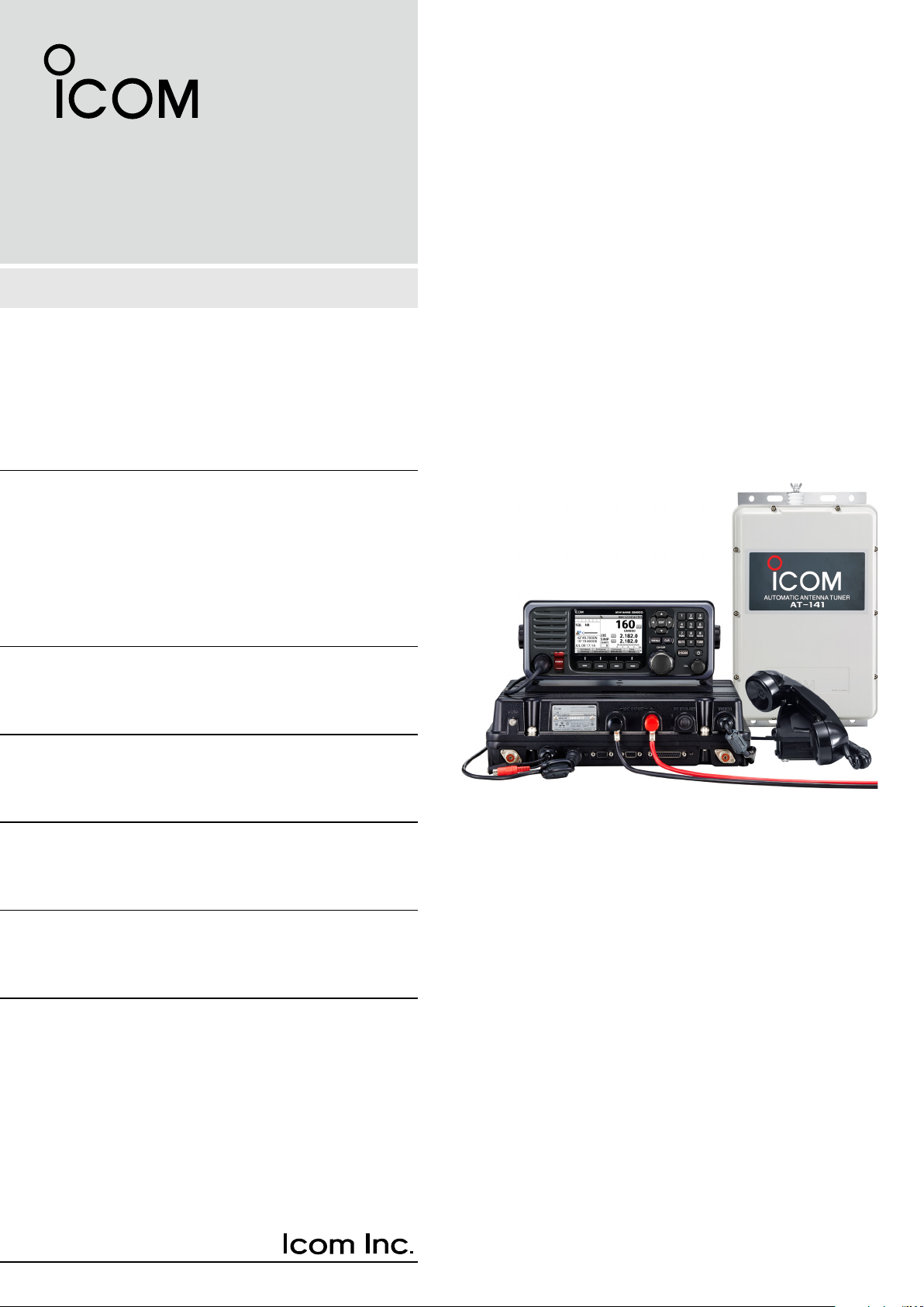
MF/HF MARINE TRANSCEIVER
GM800
Page 2

Thank you for choosing this Icom product.
The GM800 mf/hf marine transceiver is designed
and built with Icom’s state of the art technology and
craftsmanship. With proper care, this product should
provide you with years of trouble-free operation.
The GM800 has Class A DSC functions for Distress
alert transmission and reception, as well as general
DSC calls (Individual call, Group call Geographical
call, Position Request call, Polling Request call, and
Test call).
IMPORTANT
READ ALL INSTRUCTIONS carefully and
completely before using the transceiver.
SAVE THIS INSTRUCTION MANUAL — This
instruction manual contains important operating
instructions for the GM800.
NOTE: This transceiver receives the frequency
range30kHz~500kHzintheJ3Emode,butit
has not been tested and Icom does not warrant
the operation in this frequency range. Thus this
transceiver does not conform to the permission of
thefrequencyrange415kHz~526.5kHzwhichis
permitted by the ITU Radio Regulations [3].
To stabilize the output frequency:
±10Hzfrequencystabilityrequiresawarminguptime
period.
The warming up time period is within 30 minutes after
turning ON the transceiver’s main power, and it differs
depending on the output temperature.
IN CASE OF EMERGENCY
When your ship requires assistance, contact other
ships and the Coast Guard by sending a Distress call
using DSC (digital selective calling) on an Emergency
frequency.
When immediate help is needed:
1. To send a Distress call, hold down [DISTRESS]
for 3 seconds until the short beeps become one
long beep.
2. Release [DISTRESS] and wait for an
acknowledgment.
3. After receiving the acknowledgement call, hold
down [PTT] on the microphone and send the
following information.
1 “MAYDAY, MAYDAY, MAYDAY.”
2 “THIS IS . . . . . . . . (name of ship).”
3 “LOCATED AT . . . .(ship’s position).”
4 Give the reason for the distress call.
5 Explain what assistance you need.
6 Give additional information about your ship:
•Type
•Length
•Color
•Thenumberofpeopleonboard
Icom is not responsible for the destruction, damage
to, or performance of any Icom or non-Icom
equipment, if the malfunction is because of:
•Forcemajeure,including,butnotlimitedto,res,
earthquakes,storms,oods,lightning,other
natural disasters, disturbances, riots, war, or
radioactive contamination.
•TheuseofIcomtransceiverswithanyequipment
that is not manufactured or approved by Icom.
Icom, Icom Inc. and the Icom logo are registered
trademarksofIcomIncorporated(Japan)inJapan,the
United States, the United Kingdom, Germany, France,
Spain, Russia, Australia, New Zealand, and/or other
countries.
i
EXPLICIT DEFINITIONS
WORD DEFINITION
RDANGER!
RWARNING!
CAUTION
NOTE
Personal death, serious injury or an
explosion may occur.
Personalinjury,rehazardor
electric shock may occur.
Equipment damage may occur.
If disregarded, inconvenience only.
Noriskofpersonalinjury,reor
electric shock.
Page 3

PRECAUTIONS
RDANGER HIGH RF VOLTAGE! NEVER touch
an antenna while transmitting. This may result in an
electrical shock or burn.
RWARNING! NEVER operate the transceiver during
a lightning storm. It may result in an electric shock,
causeareordamagethetransceiver.Always
disconnect the power source and antenna before a
storm.
RWARNING! NEVER directly connect the
transceivertoanACoutlet.Thismayposeare
hazardorresultinanelectricshock.
RWARNING! NEVER mount the transceiver main
unit overhead. The weight of the unit is approximately
8.5kg,anditcouldeasilyfallduetowaveshocksor
vibration.Theunitmustbemountedonaathard
surface only.
RWARNING! NEVER connect a power source of
more than 31.2 V DC. This connection could cause a
reorruinthetransceiver.
RWARNING! NEVER place the transceiver where
normal operation of the ship may be hindered, or
where it could cause bodily injury.
RWARNING! NEVER let metal, wire or other objects
protrude into the transceiver or into connectors on the
rear panel. This may result in an electric shock.
CAUTION: DO NOT use harsh solvents such as
benzineoralcoholwhencleaning,becausetheywill
damage the transceiver’s surfaces.
CAUTION: DO NOT place the transceiver in
excessively dusty environments or in direct sunlight.
CAUTION: DO NOT use non-Icom handsets or
microphones. Other manufacturer’s handset or
microphones have different pin assignments,
and connection to the GM800 may damage the
transceiver.
CAUTION: DO NOT place the transceiver against
walls or putting anything on top of the transceiver.
This may overheat the transceiver.
BE CAREFUL! The transceiver main unit will become
hot when operating the transceiver continuously for
long periods of time.
BE CAREFUL! The remote controller’s front panel
meets IPX7* requirements for waterproof protection.
However, once the transceiver has been dropped,
or the waterproof seal is cracked or damaged,
waterproof protection cannot be guaranteed because
of possible damage to the case or the waterproof
seal.
* The connectors on the rear panel do not meet IPX7.
NOTE: The LCD display may have cosmetic
imperfections that appear as small dark or light spots.
This is not a malfunction or defect, but a normal
characteristic of LCD displays.
NOTE: Install the transceiver and handset or
microphone as far away as possible, (at least 1
meter), from the magnetic navigation compass, to
prevent erroneous indications.
CAUTION: DO NOT use the transceiver in areas with
temperaturesbelow–15°Corabove+55°C.
RECOMMENDATION
CLEAN THE REMOTE CONTROLLERʼS FRONT
PANEL THOROUGHLY IN A BOWL OF FRESH
WATER after exposure to saltwater, and dry it
beforeoperating.Otherwise,theremotecontrollerʼs
keys, switches may become unusable, due to salt
crystallization.
L The connectors on the rear panel do not meet IPX7.
NOTE: Always place unit in a secure place to avoid
inadvertentusebyunauthorizedpersons.
NOTE: If the remote controller’s waterproof
protection appears defective, carefully clean it with
a soft, damp (fresh water) cloth, then dry it before
operating. The remote controller may lose its
waterproof protection if the case, or connector cover
is cracked or broken, or the remote controller has
been dropped. Contact your Icom distributor or your
dealer for advice.
ii
Page 4

INSTALLATION NOTE
DISPOSAL
Installation:
The installation of this equipment should be made in
such a manner as to respect the EC recommended
electromagneticeldexposurelimits.(1999/519/EC)
The maximum RF power available from this device is
150watts.Theantennashouldbeinstalledashighas
possibleformaximumefciencyandtheinstallation
height should be at least 2.0 meters above any
accessible position. In the case where an antenna
cannot be installed at a reasonable height, then the
transmitter should neither be continuously operated
for long periods if any person is within a distance of
2.0 meters of the antenna, nor operated at all if any
person is touching the antenna.
It is recommended that antenna of a maximum gain
of 0 dBd is used. If higher gain antenna are required
then please contact your Icom distributor for revised
installation recommendations.
Operation:
TheexposuretoRFelectromagneticeldisonly
applicable when this device is transmitting. This
exposure is naturally reduced due to the nature of
alternating periods of receiving and transmitting.
Keep your transmissions to the minimum necessary.
The crossed-out wheeled-bin symbol on
your product, literature, or packaging
reminds you that in the European Union,
all electrical and electronic products,
batteries, and accumulators
(rechargeable batteries) must be taken to
designated collection locations at the end
of their working life. Do not dispose of
these products as unsorted municipal
waste. Dispose of them according to the
laws in your area.
iii
Page 5

TABLE OF CONTENTS
1. OPERATING RULES ...............1
2. PANEL DESCRIPTION ........2–7
■ Main unit .......................................... 2
■ Remote Controller front panel .......... 3
■ Handset ............................................ 4
D About the Speaker Switch ........... 4
■ Optional HM-214H ........................... 4
■ Software Key function ...................... 4
D Selecting the Software Key
function ........................................ 4
D Functions ..................................... 5
■ Function display (Main screen) ........ 6
D Status area .................................. 6
D Information area .......................... 6
D Channel and Frequency area ...... 6
D Task area ..................................... 6
D Position Date and Time area ....... 7
3. PREPARATION ........................8
■ Entering the MMSI code .................. 8
4. MENU SCREEN .................9–10
■ Menu Construction ........................... 9
■ Selecting the item .......................... 10
5. BASIC OPERATION ........ 11–12
■ Selecting a Channel or Group ........ 11
D Using the channel and group
selector ...................................... 11
D Using the keypad ....................... 11
■ Receiving and transmitting ............. 12
D Receiving ................................... 12
D Transmitting ............................... 12
■ DSC scan ....................................... 12
6. OTHER FUNCTIONS AND
OPERATIONS .................. 13–22
■ Backlight function ........................... 13
■ Scan ............................................... 14
D Channel scan and Channel
Resume scan ............................ 14
D Programmed scan ..................... 14
■ Other functions ............................... 15
D Transmit Frequency Monitor
function ...................................... 15
D Squelch function ........................ 15
D S-meter squelch level ................ 15
D Noise Blanker function .............. 15
D Noise blanker level .................... 15
D Automatic Gain Control OFF ..... 16
D RF gain level ............................. 16
D Clarity Control function .............. 16
D Automatic Antenna Tuner function
■ Setting a temporary operating
frequency ....................................... 17
■ Setting a User channel or an ITU
Simplex channel ............................. 18
■ Assigning a function ....................... 20
D Assigning a Software Key function
to a Software Key ...................... 20
D Assigning a Software Key function
to [VOL] ..................................... 21
.. 16
D Assigning a Software Key
function to [P] on the HM-214H
microphone ������������������������������� 22
7. DSC OPERATION ............ 23–74
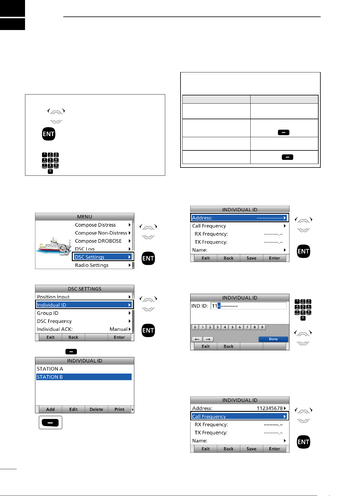
■ DSC adress ID ............................... 23
D Entering an Individual ID ........... 23
D Entering a Group ID .................. 25
D Deleting an entered ID .............. 26
■ Entering position data and time ..... 27
■ DSC Task mode ............................. 29
D About “Active” and “Hold” .......... 29
D Software Key functions .............. 29
■ Sending a Distress call .................. 30
D Simple call ................................. 30
D Regular call ............................... 31
D Resending a Distress call .......... 33
D Sending a Distress Cancel call .. 34
D Sending a Distress
acknowledgement ..................... 36
D Sending a Distress Relay call .... 37
D Sending a Distress Relay
acknowledgement ..................... 42
■ Sending a Non-Distress calls ......... 43
D Sending an Individual call .......... 43
D
Sending an Individual
acknowledgement ...................... 45
D Sending a Group call ................. 45
D Sending a Geographical call ..... 47
D Sending a Position Request call 50
D Sending a Position Request
acknowledgement ..................... 51
D Sending a Polling Request
acknowledgement ..................... 52
D Sending a Test call .................... 52
D Sending a Test call
acknowledgement ..................... 53
D Sending a Medical Transports call
or Ships and Aircraft call ............54
■ Receiving DSC calls ...................... 57
D Receiving a Distress Call .......... 57
D Receiving a Distress
acknowledgement ..................... 58
D Receiving a Distress Cancel call 59
D Receiving a Distress Relay call . 59
D Receiving a Distress Relay
acknowledgement ..................... 60
D Receiving an Individual call ....... 61
D Receiving an Individual
acknowledgement ..................... 61
D Receiving a Group call .............. 63
D Receiving a Geographical Area
call ............................................. 64
D Receiving a Position Request Call
D Receiving a Position Request
acknowledgement ..................... 65
D Receiving a Polling Request call 66
D Receiving a Test call .................. 66
D Receiving a Test
acknowledgement ..................... 67
D Receiving a Medical Transports call
.. 65
67
D
Receiving a Ships and Aircraft call
■ Received Call log ........................... 69
D Distress message ...................... 69
D Other messages ........................ 69
■ Transmitted Call log ....................... 69
■ DSC Settings ................................. 70
D DSC Frequency ......................... 70
D Automatic acknowledgement .... 71
D Setting the “Medical Transports”
item display option ..................... 72
D Setting the “Ships and Aircraft”
item display option ..................... 72
D Distress Scanning Receiver ...... 72
D Setting the 10 Second Delay ..... 73
D Setting the Alarm Status ............ 73
D Auto Print ................................... 74
D DSC Loop Test .......................... 74
. 68
8. MENU ITEMS ...................75–77
■ Menu items .................................... 75
■ Radio Settings ................................ 75
■ Conguration .................................. 76
9. CONNECTIONS AND
INSTALLATION ................78–86
■ Supplied accessories ..................... 78
■ Basic connections .......................... 78
■ Advanced connections .................. 79
■ Ground connection ......................... 80
■ Software maintenance ................... 80
■ Power source ................................. 81
■ Antenna .......................................... 81
■ Mounting ........................................ 82
D Mounting location ...................... 82
D Attaching the mounting plates .. 82
D Mounting the remote controller . 82
D Mounting the main unit .............. 82
■ Using the optional MB-108
■ Replacing fuses ............................. 84
■ Connector information .................... 85
■ Transceiver dimensions ................. 86
............. 83
10. SPECIFICATIONS AND
OPTIONS .........................87–88
11. TROUBLESHOOTING ........... 89
12. DIGITAL INTERFACE
(IEC 61162-1) ...................90–93
■ I/O Sentences ................................ 90
D Version number ......................... 90
D GPSInputsentences(IEC61162-1)
.................................................. 90
D GPS Input sentence description 90
D Remote Input and Out
putsentences(IEC61162-1) ...... 91
D Remote sentence description .... 91
■ Schematic diagram ........................ 92
■ Hardware version ........................... 93
■ Software version ............................ 93
INDEX...........................................94
iv
Page 6

1
NOTE: Before transmitting, monitor the channel you
want to use to avoid interrupting communications
already in progress.
OPERATING RULES
• CALL PROCEDURE
Calls must be properly identied and the time limit
must be respected.
1. Give your call sign each time you call another
ship or coast guard station. If you have no call
sign, identify the station by giving your ship name
and the name of the licensee.
2. Give your call sign at the end of each
transmission that lasts more than 3 minutes.
3. You must break and give your call sign at least
once every 15 minutes during long ship-to-shore
calls.
4. Keep your unanswered calls short, less than 30
seconds. Do not repeat a call for 2 minutes.
5. Unnecessary transmissions are not allowed.
• PRIORITIES
1. Read all rules and regulations pertaining to
priorities and keep an up-to-date copy handy.
Safety and Distress calls take priority over any
other calls.
2. False or fraudulent Distress signals are prohibited
and punishable by law.
• PRIVACY
1. Information overheard but not intended for you,
cannot lawfully be used in any case.
2. Indecent or profane language is prohibited.
• LOGS
1. All Distress, Emergency and Safety calls must
be recorded in complete details. Log data activity
is usually recorded for 24 hours. Universal Time
Coordinated (UTC) is frequently used.
2. Keep adjustments, repairs, channel frequency
changes and authorized modications affecting
electrical operation of the equipment in the
maintenance log. The entries requires signatures
by the authorized licensed technician performing
or supervising the work.
• RADIO LICENSES
(1) SHIP RADIO STATION LICENSE
You need a current ship radio station license before
using the transceiver. It is unlawful to operate a ship
radio station which is not licensed, but required to be.
If required, contact your dealer or the appropriate
government agency for a Ship-Radiotelephone
license application. This government-issued license
states the call sign which is your craft’s identication
for radio communication purposes.
(2) OPERATOR’S LICENSE
A Restricted Radiotelephone Operator Permit is
the license most often held by small vessel radio
operators when a radio is not required for safety
purposes.
If required, the Restricted Radiotelephone Operator
Permit must be posted or kept with the operator. If
required, only a licensed radio operator may operate
a transceiver.
However, non-licensed individuals may talk over a
transceiver if a licensed operator starts, supervises,
ends the call and makes the necessary log entries.
A current copy of the applicable government rules
and regulations is only required to be on hand for
vessels in which a radio telephone is compulsory.
However, even if you are not required to have these
on hand it is your responsibility to be thoroughly
acquainted with all pertinent rules and regulations.
1
Page 7
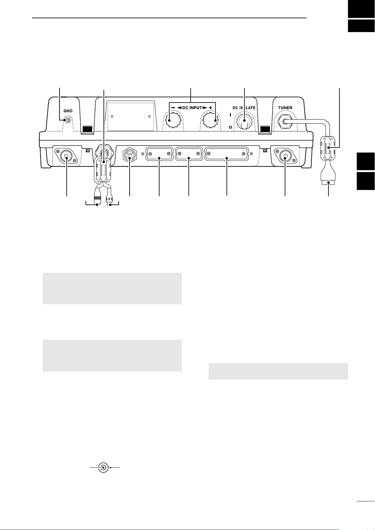
■ Main unit
hf automatic antenna tuner
hf automatic antenna tuner
FERRITE EMI FILTER FERRITE EMI FILTER
q
PANEL DESCRIPTION
!2 !1
2
Quick Reference
Quick Reference
1
2
2
e
q GROUND TERMINAL [GND]
Connect to the ship’s ground. (p. 81)
w DSC ANTENNA CONNECTER
Connect to a 50 Ω HF marine band antenna
through a 50 Ω coaxial cable with a PL-259 plug.
This antenna is used for receiving Distress calls.
NOTE: To receive a Distress call, BE SURE
to connect an HF marine band antenna to this
antenna connector. Otherwise, you cannot
receive any Distress calls.
e SPEAKER JACK [SP]
Connect to the SP-24 (p. 80) or an external
speaker.
NOTE:
SURE to turn OFF the internal speaker.
Audio is output from the external speaker only
when the internal speaker is OFF.
r GPS JACK [GPS]
Connect to a GPS receiver to input position and
UTC data for DSC operations. (IEC 61162-1
Edition 4.0 (2010-11))
• An IEC 61162-1 Edition 4.0 (2010-11) (sentence
formatters: GGA) compatible GPS receiver is
required. Ask your dealer about suitable GPS
receivers.
t CONTROLLER CONNECTOR [CONTROLLER]
Connect to the supplied controller.
When using an external speaker, BE
RCA
GPS IN (+)
t
(p. 5)
GPS IN (–)
oiuyrw
y MODEM SOCKET [AF/MOD] (p. 87)
Connect to an external terminal unit for SSB
mode operation through an RS-232C cable
(D-sub 15-pin).
u REMOTE SOCKET [REMOTE] (p. 88)
Connect to a PC through an RS-232C cable
(D-sub 9-pin) for remote control.
i PRINTER CONNECTOR
Connect to an IBM
printer to automatically or manually print out
received DSC information.
o ANTENNA CONNECTOR
Connect to a wire or whip antenna through the
AT-141
antenna is used for transmitting any calls and
receiving any calls other than Distress calls.
RWARNING! NEVER directly connect the
antenna to this connector.
!0 TUNER CONTROL SOCKET [TUNE]
Connect to the control cable of the supplied
AT-141
connector kit is supplied to connect the AT-141.
!1 POWER SWITCH [DC ISOLATE]
Turns the transceiver’s main power ON or OFF.
When the main power is ON, the power key's
backlight is dimly lit.
!2 DC POWER TERMINALS
Connect to a 24 V DC power source through the
supplied DC power cables. The red terminal is
positive (+) and the black terminal is negative (–).
®
centronics or compatible
!0
. The
. A female
2
3
3
4
4
5
5
6
6
7
7
8
8
9
9
10
10
11
11
12
12
13
13
14
14
15
15
16
16
17
17
Page 8
2
PANEL DESCRIPTION
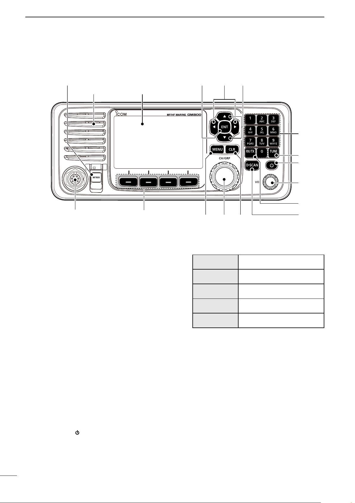
■ Remote Controller front panel
q w e
SPEAKER FUNCTION DISPLAY (p. 6)
SOFTWARE KEYS (p. 4)MIC CONNECTOR
q DISTRESS KEY [DISTRESS]
Hold down for 3 seconds to transmit a Distress
call. (p. 30)
r
!1!2!3
i VOLUME DIAL [VOL]
Rotate to adjust the speaker volume level.
Push 1 ~ 5 times to display the setting screens.
t
y
u
i
o
!0
w ENTER KEY [ENT]
Push to set the entered data, selected item, and
so on.
e LEFT AND RIGHT KEYS [Ω]/[≈]
Push to scroll the Software Key functions.
(p. 4)
In the Character or Number Entry mode, push
to select a character or number in the table.
r UP AND DOWN KEYS [∫]/[√]
Push to select an operating channel, menu items,
menu settings, and so on.
t KEYPAD
Push to enter numbers, letters or symbols.
y TUNE KEY [TUNE]
Push to turn ON the Automatic Antenna Tuner
function, or to go through (bypass) the tuning
circuit. (p. 16)
Hold down to start manual tuning.
L After tuning is completed, “TUNE” is displayed.
L When the tuner cannot tune the antenna, “THRU”
is displayed.
u
POWER KEY [ ]
Hold down for 1 second to turn the transceiver
ON or OFF.
Pushing once
Pushing twice
Pushing 3 times
Pushing 4 times
Pushing 5 times
o RX/TX KEY [RX/TX]
The Volume Setting window is
displayed.
The NB Level Setting window is
displayed.
The S-SQL Level Setting window
is displayed.
The RF Gain Setting window is
displayed.
The Backlight Settings window is
displayed.
Push to set a temporary operating frequency. (p. 17)
!0 DSC SCAN KEY [D-SCAN]
Push to start a DSC scan. (p. 12)
!1 CLEAR KEY [CLR]
Push to cancel the entered data, or to return to
the previous screen.
!2 CHANNEL/GROUP SELECTOR [CH/GRP]
Push to select the Channel Select mode or the
Group Select mode. (p. 11)
Push to set the entered data, selected item,
and so on.
Rotate to select the operating channel, menu
items, menu settings, and so on.
!3 MENU KEY [MENU]
Push to enter or exit the Menu screen.
3
Page 9
PANEL DESCRIPTION
2
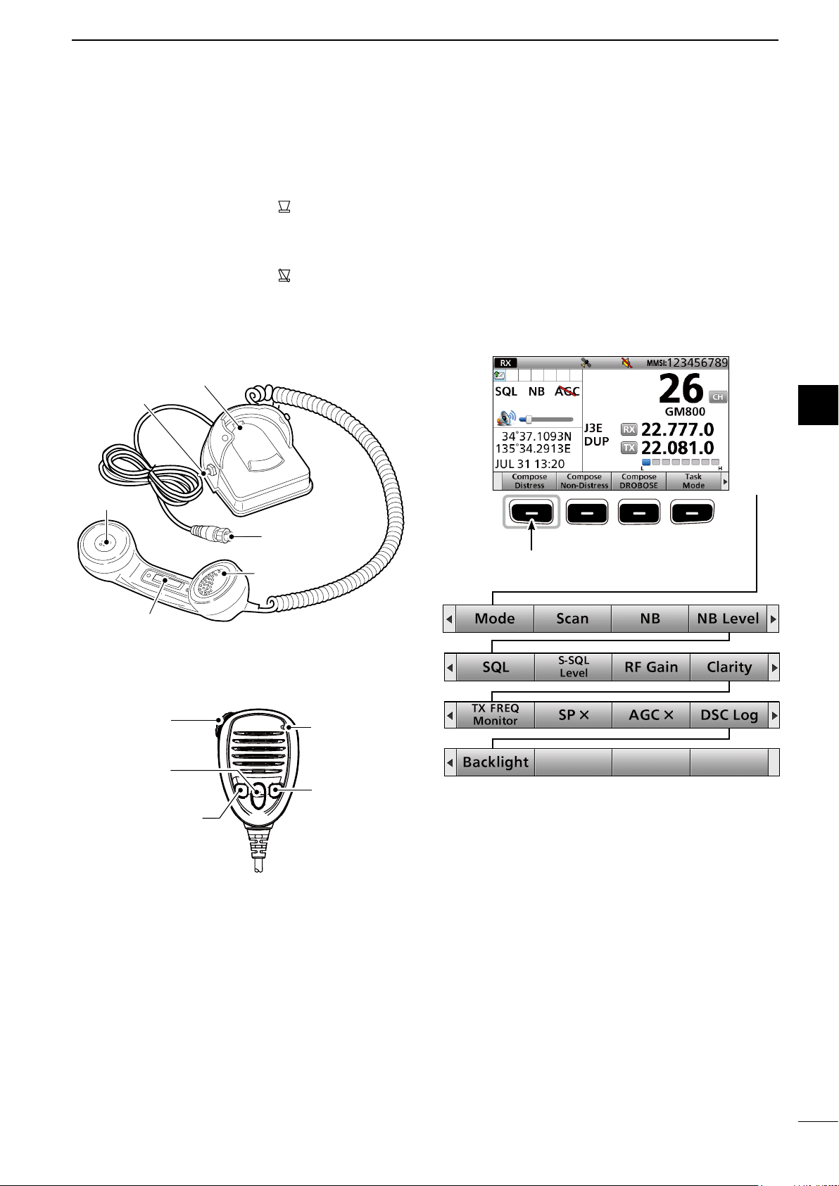
■ Handset
D About the Speaker Switch
When the switch is set to the “ ” position:
You can hear the receive audio from the remote
controller's speaker.
When the switch is set to the “ ” position:
Mutes the remote controller speaker output.
• You can hear the receive audio from the handset.
Put the handset into the cradle to output the hear
audio from the remote controller's speaker.
Cradle
Speaker switch
Speaker
Handset connector
Microphone
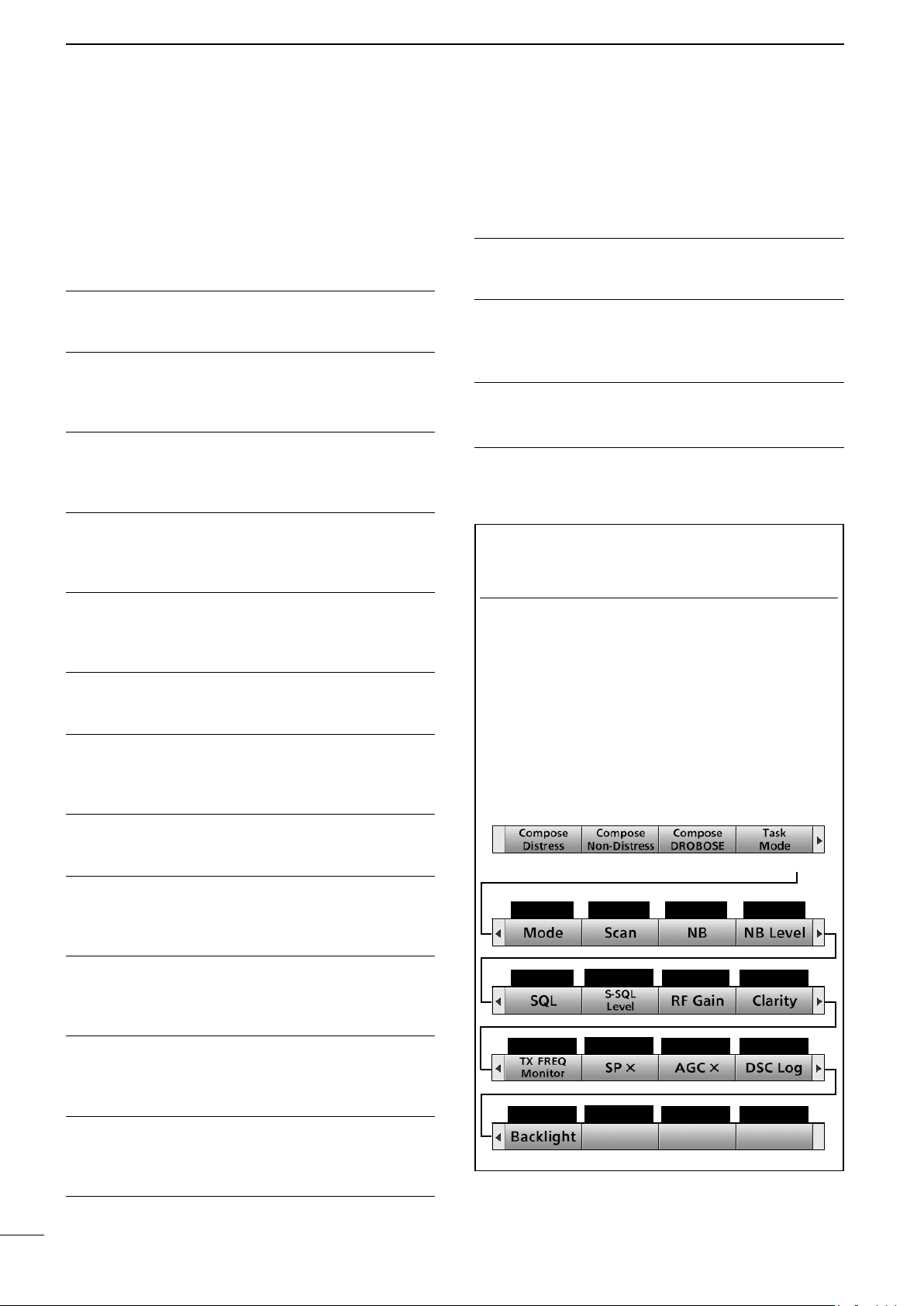
■ Software Key function
The transceiver has Software Keys for various
functions. The key's function is displayed above
them, as shown below.
D Selecting the Software Key function
When “Ω” or “≈” is displayed beside the key icon,
pushing [Ω] or [≈] scrolls the Software Key functions.
When you push [Ω] or [≈] once, 4 functions scroll
together.
Push [≈]
Push this Software Key to
compose a Distress call.
Quick Reference
1
2
3
4
5
6
PTT switch [PTT]
■ Optional HM-214H
q PTT SWITCH
[PTT]
w UP/DOWN
KEYS [▲]/[▼]
e PROGRAMMABLE
KEY [P]
q PTT SWITCH
Hold down to transmit, release to receive.
w UP/DOWN KEYS [▲]/[▼]
Push to select an operating channel or group.
e PROGRAMMABLE KEY [P]
Push to activate the preset Software Key function.
Ask your dealer for details.
You can reassign some Software Key functions to
the key. (p. 20)
r DSC SCAN KEY [D-SCAN]
Push to start the DSC scan. (p. 12)
MICROPHONE
r [D-SCAN]
Push [Ω]
Push [Ω]
Push [≈]Push [Ω]
7
8
Push [≈]
9
Push [≈]
10
11
12
13
14
15
16
17
4
Page 10
2
PANEL DESCRIPTION
■ Software Key function
D Functions
You can use various Software Key functions that are
assigned to the Software Keys, as described below.
Compose Distress
Push to compose a Distress call. (pp. 30 ~ 42)
Compose Non-Distress
Push to compose DSC calls other than Distress calls.
(pp. 43 ~ 56)
Compose DROBOSE
Push to compose a Distress Relay On Behalf Of
Someone Else (DROBOSE) call. (p. 37)
Task Mode
When the transceiver has any DSC tasks, push to
enter the DSC Task mode. (p. 29)
Mode
Push to select the J3E, H3E, LSB, J2B, F1B, or A1A
operating mode.
Scan
Push to start or stop a scan. (p. 14)
SP ×
Push to turn the speaker output ON or OFF.
AGC ×
Push to
turn the Automatic Gain Control (AGC)
function ON or OFF. (p. 16)
DSC Log
Push to check the received DSC calls. (p. 69)
Backlight
Push to change the brightness of the backlight.
(p. 13)
TIP: You can reassign the functions’ place to meet
your needs. (Soft Key 5 ~ Soft Key 20). For details
about how to assign them, see page 20.
InformationL
The rst set of Software Key functions ([Compose
Distress], [Compose Non-Distress],
[Compose DROBOSE], and [Task Mode]) are xed
and cannot be reassigned.
NB
Push to turn the Noise Blanker (NB) function ON or
OFF. (p. 15)
NB Level
Push to adjust the NB level. (p. 15)
SQL
Push to turn the Squelch function ON or OFF.
(p. 15)
S-SQL Level
Push to adjust the S-meter Squelch (S-SQL) level.
(p. 15)
RF Gain
Push to adjust the Radio Frequency (RF) gain level.
(p. 16)
Clarity
Push to turn the Clarity Control function ON or OFF.
(p. 16)
Push [►] to select the second set (Soft Key 5 ~ Soft
Key 8), the third set (Soft Key 9 ~ Soft Key 12), the
forth set (Soft Key 13 ~ Soft Key 16), and the fth
set (Soft Key 17 ~ Soft Key 20) of Software Key
functions.
Push [≈]
Soft Key 5
Soft Key 9
Soft Key 13
Soft Key 17
Soft Key 6
Soft Key 10
Soft Key 14
Soft Key 18
Soft Key 7 Soft Key 8
Soft Key 11 Soft Key 12
Soft Key 15 Soft Key 16
Soft Key 19 Soft Key 20
TX Freq Monitor
Push to check and monitor the transmit frequency.
(p. 15)
5
Page 11
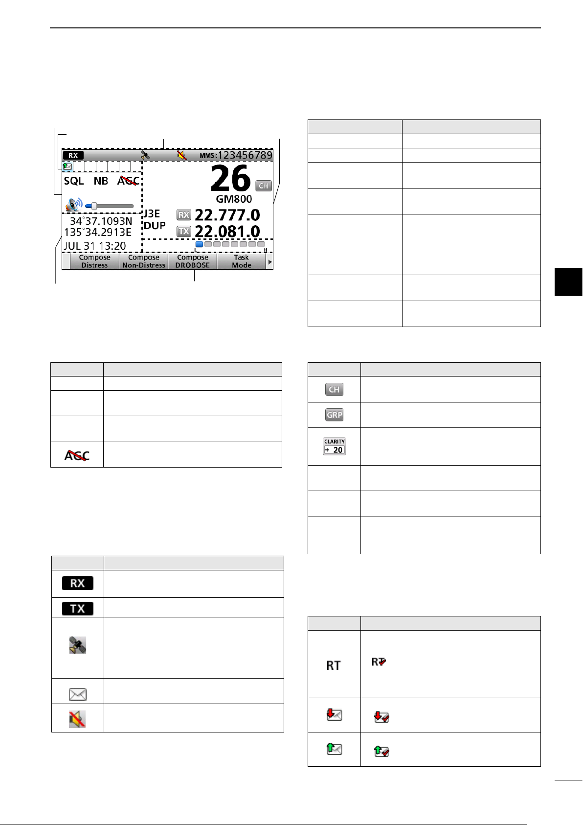
■ Function display (Main screen)
PANEL DESCRIPTION
2
q Status area
w Task area
u Position Date and Time area
e Information area
r Channel and
Frequency area
t
y Software Key area
D Status area
Indication Description
Scan Displayed during a scan.
NB
SQL
Displayed when the Noise Blanker
function is ON.
Displayed when the Squelch function is
ON.
Displayed when the AGC function is
OFF.
D Information area
The 9 digit MMSI (Maritime Mobile Service Identity:
DSC self ID) code and the following indications are
displayed in the Information area.
Indication Description
Displayed when receiving a signal or
when the squelch is open.
Displayed while transmitting.
Displayed when the GPS receiver is
activated and valid position data is
received.
Blinks while invalid position data is
being received.
Blinks when there is an unread DSC
message.
Displayed when the internal speaker is
OFF.
Display area Description
q Status area
w Task area
e Information
area
r Channel and
Frequency area
t S/RF Meter
y Software Key
area
u Position Date
and Time area
Displays the current status.
Displays up to 7 task icons.
Displays various icons and the
MMSI code.
Displays the selected
operating channel information.
• Displays the relative signal
strength of the receive
signal.
• Displays the output power
level of the transmit signal.
Displays the key function for
each Software Key.
Displays the current position,
date and time.
D Channel and Frequency area
Indication Description
Displayed when the Channel Select
mode is selected.
Displayed when the Group Select mode
is selected.
Displayed when the Clarity function is
ON. The number displays the added or
subtracted frequency.
SIMP
DUP
J3E/H3E/
LSB/J2B/
F1B/A1A
Displayed when a Simplex channel is
selected.
Displayed when a Duplex channel is
selected.
Displays the selected operating mode.
D Task area
Up to 7 task icons are displayed in the Task area
when the transceiver has a task.
Indication Description
Displayed while in the Radio Telephone
(RT) mode.
• “ ” is displayed when the RT mode task
is activated.
• Disappears if no operation occurs during
the preset period of time.
Displayed after receiving a DSC call.
• “ ” is displayed when the RX call task is
activated.
Displayed after making a DSC call.
• “ ” is displayed when the TX call task is
activated.
Quick Reference
1
2
3
4
5
6
7
8
9
10
11
12
13
14
15
16
17
6
Page 12
2
PANEL DESCRIPTION
■ Function display (Main screen)
D Position Date and Time area
POSITION AREA
The current position is displayed when valid GPS
data is received, or when you manually enter your
position.
Indication Description
NO
POSITION
Displayed when a GPS receiver is
not connected and the position has
not been manually entered.
?? Blinks every 2 seconds instead of the
position when the GPS position data
is invalid.
• The last position is held for only 23.5
hours. After that, “NO POSITION” will be
displayed.
Blinks every 2 seconds instead of the
position after 4 hours have passed
since you manually entered the
position.
• The manually entered position is held
for only 23.5 hours. After that, “NO
POSITION” will be displayed.
DATE AND TIME AREA
• The current time is displayed when valid GPS data
is received, or manually enter the time.
• The date information is displayed when the RMC
GPS sentence formats are included in the GPS
signal.
Indication Description
NO TIME Displayed when a GPS receiver is not
connected and the time has not been
manually entered.
Local Displayed when the offset time is set.
Manual Displayed when the time is manually
entered.
UTC Displayed when the GGA, GLL or GNS
GPS sentence formats are included in
the GPS signal.
?? Blinks every 2 seconds instead of the
time when the GPS current time is
invalid.
• After 23.5 hours has passed, “NO TIME”
will be displayed.
Blinks every 2 seconds instead of the
time after 4 hours have passed since
you manually entered the time.
• The manually entered time is held for only
23.5 hours. After that, “NO TIME” will be
displayed.
7
Page 13
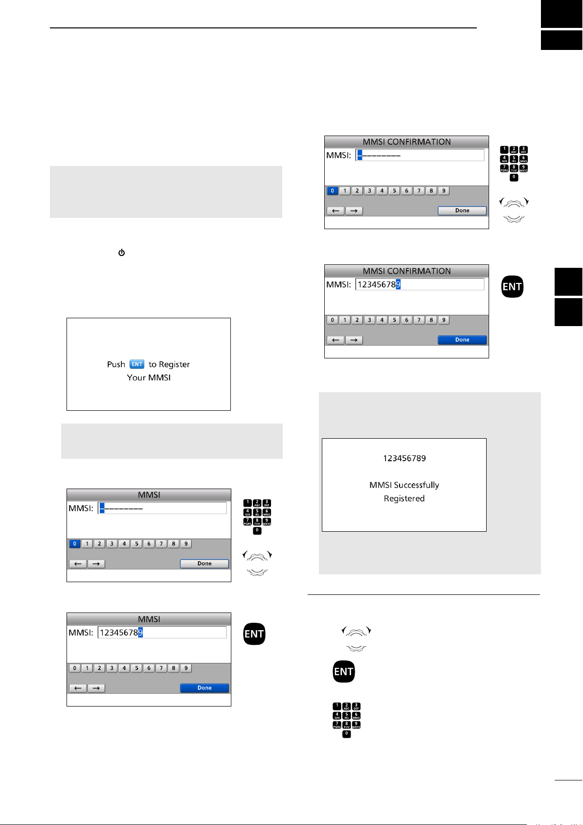
■ Entering the MMSI code
Rotate
+
Push
CH/GRP
Rotate
+
Push
CH/GRP
PREPARATION
3
First, you must enter your 9 digit MMSI (Maritime
Mobile Service Identity: DSC self ID) code at power
ON.
You can perform this initial code entry ONLY
ONCE. After entry, only your dealer or distributor
can change it. If you have already entered your
MMSI code, these procedures are not necessary.
Example: Entering the MMSI code (123456789).
1. Hold down [
transceiver.
• Three short beeps sound.
• “ Push [ENT] to Register Your MMSI” is displayed.
2. Push [ENT].
NOTE: Push [CLR] to cancel the entry. In that case,
the transceiver displays “Push [ENT] to Register Your
MMSI” again.
3. Enter your 9 digit MMSI code.
] for 1 second to turn ON the
Push
5. Reenter your MMSI code to confirm.
6. After entering the 9th digit, push [ENT].
• The MMSI code is registered.
NOTE:
When you successfully enter your MMSI code, the
following screen is displayed.
Push
+
Rotate
CH/GRP
to select
a character
Quick Reference
1
2
3
4
5
6
7
8
9
Rotate
CH/GRP
to select
a character
4. After entering the 9th digit, push [ENT].
• The MMSI CONFIRMATION screen is displayed.
+
After that, the Main screen is displayed.
The registered MMSI code is displayed at the top of the
screen.
11
12
10
InformationL
13
Rotate
CH/GRP
: Rotate [CH/GRP] to select.
14
Push
: Push [ENT] to enter or set.
15
Push : Push the keypad keys to enter a
digit or text.
16
17
8
Page 14

4
MENU SCREEN
You can use the Menu screen to set infrequently
changed values or function settings.
■ Menu Construction
The Menu screen is constructed in a tree structure.
You can go to the next tree level by pushing [ENT], or
go back a level by pushing [CLR]. See the next page
for details.
Compose Distress
Nature of Distress
Position
• Latitude
• Longitude
• UTC
Mode
Attempt
Compose DROBOSE
Message Type
Address
1
Area*
• Latitude*
• Longitude*
• Radius*
1
1
1
• Behind You*
• To Your Right*
Compose Non-Distress
Message Type
Address*
Area*
• Latitude*
• Longitude*
• Radius*
• Behind You*
• To Your Right*
1
1
1
1
1
1
1
Category
Call Frequency
• RX Frequency
• TX Frequency
1
Mode*
Comm Frequency*
• RX Frequency*
• TX Frequency*
1
1
1
Distress ID
Nature of Distress
Position
• Latitude
• Longitude
• UTC
Call Frequency
• RX Frequency
• TX Frequency
Mode
Comm Frequency
• RX Frequency
• TX Frequency
DSC Log
Received Call Log
• Distress
• Others
Transmitted Call Log
9
To select an item, rotate [CH/GRP].
Rotate
DSC Settings
Position Input*
2
Individual ID
Group ID
DSC Frequency
Individual ACK
Position ACK
1
1
Polling ACK
Test ACK
Medical Transports
Ships and Aircraft
Distress Scanning Receiver
10 Second Delay
Alarm Status
• Safety
• Routine
• Warning
• Self-Terminate
• Discrete
Auto Print
DSC Loop Test
Radio Settings
User CHAN
ITU Simplex CHAN
Max User CHAN
Auto Tune
Scan
Voice SQL
Conguration
Key Beep
NMEA Data Output
• DSC Data Output
Assignment
UTC Offset
Inactivity Timer
• Not DSC Related
• DSC Related
• RT Related-J3E/
H3E/LSB/J2B/F1B/
A1A
• Distress Related
CH/GRP
MIC Key
Software Version
*1 These items may not be displayed, depending on
the “Message Type” option.
*2 This item is not displayed when valid GPS data is
received.
Page 15
■ Selecting the item
CH/GRP
CH/GRP
CH/GRP
MENU SCREEN
4
Follow the procedures described below to select a
Menu item.
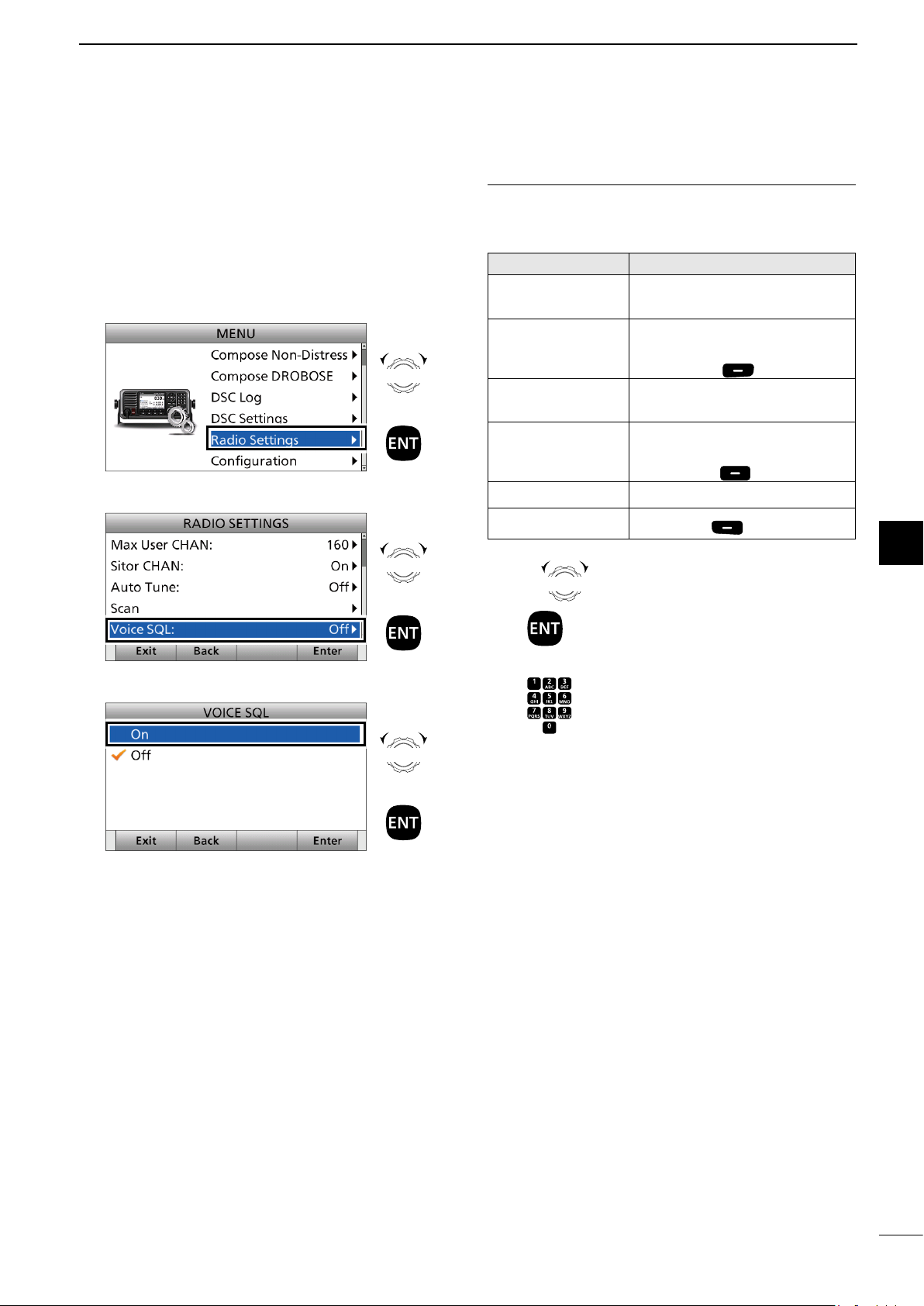
Example: Turning ON the Voice Squelch function.
1. Push [MENU].
2. Select “Radio Settings.”
Rotate
+
Push
3. Select “Voice SQL.”
Rotate
+
Push
4. Select “On.”
Rotate
InformationL
You can use the following key functions in the MENU
screen.
FUNCTION ACTION
Select Rotate [CH/GRP], or
Push [∫] or [√]
Enter Push [ENT],
Push [CH/GRP], or
Push [Enter]
Go to the next
tree level
Go back to the
previous tree
level
Cancel Push [CLR]
Exit
Rotate
Push : Push [ENT] to enter or set.
Push : Push the keypad keys to enter a
CH/GRP
Push [ENT] or
Push [≈]
Push [CLR],
Push [Ω], or
Push [Back]
Push [Exit]
: Rotate [CH/GRP] to select.
digit or text.
Quick Reference
1
2
3
4
5
6
7
8
• Returns to the “RADIO SETTINGS” screen.
5. Push [MENU] to return to the Main screen.
+
Push
9
10
11
12
13
14
15
16
17
10
Page 16
5
ghi
abc
tuv
ghi
abc
Jkl
Jkl
ghi
abc
Jkl
abc
BASIC OPERATION
■ Selecting a Channel or Group
D Using the channel and group selector
1. Push [CH/GRP] to toggle the Channel Select
mode or the Group Select mode.
• “ ” or “ ” is displayed.
2. Rotate [CH/GRP] to select a channel or group.
Example
When selecting the Group Select mode, the User
channels change in 20 channel steps.
NOTE: See the Channel and Channel Group list
below.
D Using the keypad
• When selecting a User channel
1. Push the keypad keys to enter the channel
nu mber.
2. Push [ENT] to set.
Example
• Selecting CH 41: [4
•
Selecting CH 128: [1] → [2
] → [1] → [ENT]
] → [8
] → [ENT]
[ENT]
KEY PAD
• Channel Select mode • Group Select mode
[CH/GRP]
[CLR]
• When selecting an ITU simplex channel
1. Push the keypad keys to select a frequency band.
2.
Push the left most Software Key to enter “– ”
(dash).
• When selecting an ITU duplex channel
1. Push the keypad keys to enter the channel
nu mber.
Selected frequency band is
briefl y displayed.
2. Push [ENT] to set.
Example
• Selecting CH 401: [4
• Selecting CH 2505:
] → [0] →[1]→ [ENT]
[2
] → [5
[5
] → [ENT]
] →[0] →
3. Push the keypad keys to enter the channel
Push
nu mber.
4. Push [ENT] to set.
NOTE:
• See the Channel and Channel Group list below.
• Pushing [CLR] clears the entered digits and return to the
previous channel.
Example
• Selecting CH 4-1: [4
• Selecting CH 25-2:
] → →[1]→ [ENT]
[2
] → [5
[2
] → [ENT]
• Channel and Channel Group list
Channel No. Description Channel No. Description Channel No. Description
22-1 ~ 22-9
2501 ~ 2510
25-1 ~ 25-9
C1-1 ~ C1-21
C2-1 ~ C2-31
* [GRP] changes in 20 channel steps.
22 MHz ITU simplex
25 MHz ITU duplex CH
25 MHz ITU simplex
C1 channels
C2 channels
11
1 ~ 160
401 ~ 429
4-1 ~ 4-9
601 ~ 608
6-1 ~ 6-9
801 ~ 837
8-1 ~ 8-9
User CH*
4 MHz ITU duplex CH
4 MHz ITU simplex CH
6 MHz ITU duplex CH
6 MHz ITU simplex CH
8 MHz ITU duplex CH
8 MHz ITU simplex CH
1201 ~ 1241
12-1 ~ 12-9
1601 ~ 1656
16-1 ~ 16-9
1801 ~ 1815
18-1 ~ 18-9
2201 ~ 2253
12 MHz ITU duplex CH
12 MHz ITU simplex CH
16 MHz ITU duplex CH
16 MHz ITU simplex CH
18 MHz ITU duplex CH
18 MHz ITU simplex CH
22 MHz ITU duplex CH
] → →
CH
CH
Page 17

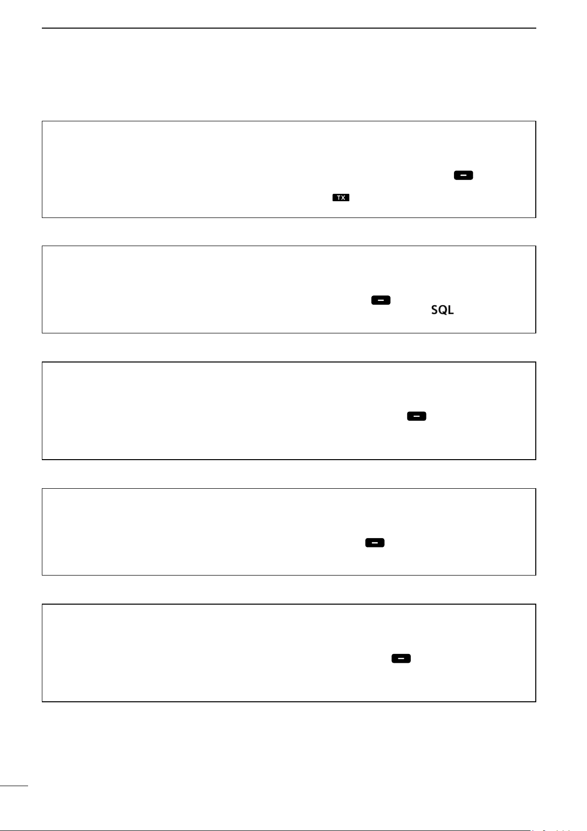
■ Receiving and transmitting
BASIC OPERATION
5
D Receiving
1. Select a channel by rotating [CH/GRP], or
pushing the keypad keys. (p. 11)
2. When receiving a call, rotate [VOL] to adjust the
audio output level.
TIP:
When a call is received:
• The icon is displayed.
• You can hear receive audio from the speaker.
• The S-meter displays the received signal strength.
D Transmitting
1. Select a channel by rotating [CH/GRP] or pushing
the keypad keys. (p. 11)
2. Push [Ω] or [≈] to display “TX FREQ Monitor” in
the Software Key area.
3. Hold down [TX FREQ Monitor]
monitor the transmit frequency of the selected
channel.
• The transmit frequency is displayed and blinks.
NOTE: If the channel is busy, wait until it becomes
clear, or change to another channel.
4. Hold down [PTT] on the handset to transmit.
• is displayed.
NOTE: If “SWR” is displayed during the transmission,
check your antenna system.
5. Speak into the microphone at your normal voice
level.
6. Release [PTT] to receive.
• is displayed.
to temporarily
[Ω]/[≈]
KEY PAD
[CH/GRP]Software Keys
NOTE: For the Time-out Timer (TOT) function
The TOT function inhibits continuous transmission
beyond a preset time period after the transmission
starts. 10 seconds before transmission is cut off, a
beep sounds to indicate the transmission will be cut
off. Release [PTT] once to end your transmission
and reset the timer. You cannot transmit for 10
seconds after it is cut off.
IMPORTANT: To maximize the readability of your
transmitted signal, pause for a second after pushing
[PTT], and then hold the handset 5 to 10 cm from
your mouth and speak at your normal voice level.
[VOL]
Quick Reference
1
2
3
4
5
6
7
8
9
10
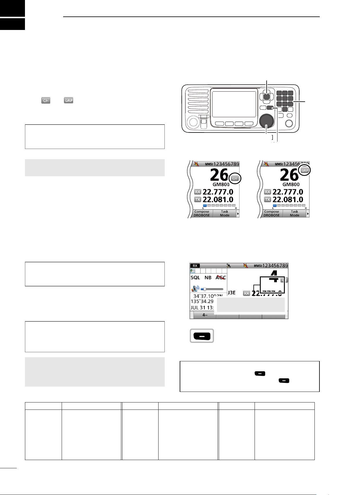
■ DSC scan
To receive a DSC call, such as an Individual call or a
Group call, push [D-SCAN] to enter the DSC watch
mode.
DSC watch mode
[D-SCAN]
NOTE: The following frequencies are always
automatically monitored with this transceiver.
2187.5, 4207.5, 6312.0, 8414.5, 12577.0, and
16804.5 kHz
11
12
13
14
15
16
17
12
Page 18
CH/GRP
6
OTHER FUNCTIONS AND OPERATIONS
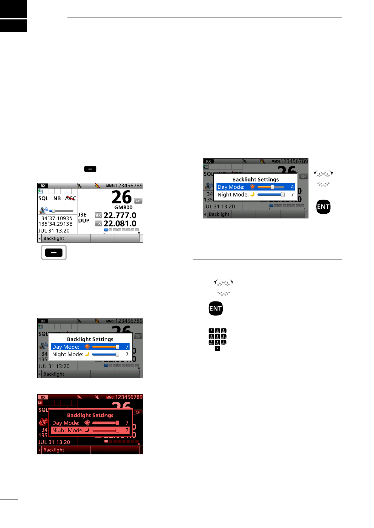
■ Backlight function
The function display and keys can be backlit for
better visibility under low light conditions.
You can set the Backlight mode to Day mode or Night
mode. The Day mode is for the daytime operation,
and the screen items are in color. The Night mode is
for the nighttime operation, and the screen items are
in black and red.
1. Push [Ω] or [≈] until “Backlight” is displayed in the
Software Key area.
2. Push [Backlight]
setting window.
3. Push [▲] or [▼] to select “Day Mode” or “Night
Mode.”
In the Backlight Setting window, if you push no key
for about 5 seconds, the transceiver automatically
returns to the Main screen.
Day mode
Push
to open the Backlight
4. Rotate [CH/ENT] to adjust the backlight level,
then push [ENT].
Rotate
+
Push
The backlight level is adjustable in 7 levels and
“OFF.” “OFF” is selectable only in the Day mode.
Information
Rotate
Push
CH/GRP
: Rotate [CH/GRP] to select.
: Push [ENT] to enter or set.
13
Push : Push the keypad keys to enter digits
or text.
Night mode
Page 19
■ Scan
OTHER FUNCTIONS AND OPERATIONS
6
The transceiver has automatic channel or frequency
scan capabilities (Scan function). There are 3 types
of scan functions.
• Channel scan
• Channel Resume scan
• Programmed scan
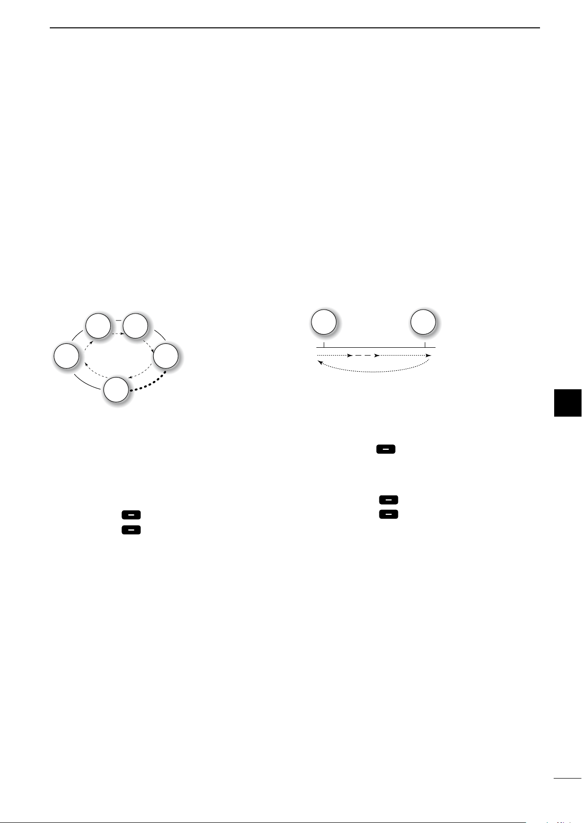
D Channel scan and Channel Resume
scan
Channel scan and Channel Resume scan channels
within a 20 channel range, such as Ch 1 to Ch 20,
Ch 141 to Ch 160, and so on, in user channels, or all
channels in the group of ITU channels.
Channel scan:
Ch 2 Ch 3
Ch 1
Ch 20
1. Rotate [GRP/CH] to select a channel group.
(p. 11)
2. Push [Ω] or [≈] until “Scan” is displayed in the
Software Key area.
3. Push [Scan]
4. Push [Scan]
Ch 4
to start a scan.
again to stop the scan.
The scan does not
pause, even if a signal
is received.
Channel Resume
scan:
The scan pauses for
10 seconds, then
resumes, or resumes
after 2 seconds from
when the signal
disappears.
Select a scan type in the Menu screen.
See page 76 for details.
D Programmed scan
The Programmed scan scans frequencies in the
frequency range between user channels.
Example:
Scans the frequencies
between channels 159
Ch 159 Ch 160
1. Push [Ω] or [≈] until “SQL” is displayed in the
Software Key area.
2. Push [SQL] to turn OFF the squelch
function.
3. Push [Ω] or [≈] until “Scan” is displayed in the
Software Key area.
4. Push [Scan]
5. Push [Scan]
to start a scan.
again to stop the scan.
and 160.
Scans quickly when
the squelch is closed.
Scans slowly when the
squelch is open.
Quick Reference
Quick Reference
1
1
2
2
3
3
4
5
5
6
6
7
7
8
8
9
9
10
10
14
11
11
12
12
13
13
14
14
15
15
16
16
17
17
Page 20
6
OTHER FUNCTIONS AND OPERATIONS
■ Other functions
D Transmit Frequency Monitor function
When selecting a duplex channel, the transmit
frequency differs from the receive frequency.
To prevent from interference to other stations, the
transmit frequency should be monitored before you
transmit.
D Squelch function
The Squelch function mutes unwanted signals such
as noise or unmodulated beat signals. This function
enables quiet standby.
However, when you need to receive weak signals,
adjust the Squelch level, or turn OFF the function.
D S-meter squelch level
When the Squelch function is ON, only signals
stronger than this set level are received.
Set to between 1 (open) and 100 (tight).
1. Push [Ω] or [≈] until “TX FREQ Monitor” is
displayed in the Software Key area.
2. Hold down [TX FREQ Monitor]
the transmit frequency.
“ ” blinks and the transmit frequency is
displayed.
1. Push [Ω] or [≈] until “SQL” is displayed in the
Software Key area.
2. Push [SQL]
When the function is ON, is displayed.
1. Push [Ω] or [≈] until “S-SQL Level” is displayed
in the Software Key area.
2. Push [S-SQL Level]
• The S-SQL level setting window is displayed.
3. Rotate [CH/GRP] to adjust the S-meter squelch
level.
to turn the function ON or OFF.
to monitor
D Noise Blanker function
The Noise Blanker function reduces pulse-type
noises that come from engine ignitions.
However, when the received strong signals are
distorted, adjust the Noise blanker level or turn OFF
the function.
D Noise blanker level
When the Noise Blanker function is ON, adjust the
Noise blanker level to reduce various pulse-type
noises.
Set to between 1 and 10.
1. Push [Ω] or [≈] until “NB” is displayed in the
Software Key area.
2. Push [NB]
When the function is ON, “NB” is displayed.
1. Push [Ω] or [≈] until “NB Level” is displayed in
the Software Key area.
2. Push [NB Level]
• The NB level setting window is displayed.
3. Rotate [CH/GRP] to adjust the Noise Blanker
level.
to turn the function ON or OFF.
.
15
Page 21
D Automatic Gain Control OFF
OTHER FUNCTIONS AND OPERATIONS
6
The Automatic Gain Control (AGC) function
prevents distortion from strong signals and
maintains a constant output level.
To receive weak signals, turn OFF the Automatic
Gain Control function.
D RF gain level
To receive weak signals, you can set the minimum
RF (Radio Frequency) gain level needed.
Set to between 0 and 9.
D Clarity Control function
With the Clarity Control function, you can slightly
shift the receive frequency without changing the
operating frequency to nely tune. When the Clarity
Control function is ON, adjust the clarity control
level.
1. Push [Ω] or [≈] until “AGC ×” is displayed in the
Software Key area.
2. Push [AGC ×]
When the function is OFF, “AGC ×” is displayed.
1. Push [Ω] or [≈] until “RF Gain” is displayed in
the Software Key area.
2. Push [RF Gain]
• The RF gain level setting window is displayed.
3. Rotate [CH/GRP] to adjust the RF gain level.
1. Push [Ω] or [≈] until “Clarity” is displayed in the
Software Key area.
2. Push [Clarity]
OFF.
When the function is ON, “ ” is displayed.
3. Rotate [CH/GRP] to adjust the clarity control.
to turn OFF the function.
to turn the function ON or
Quick Reference
1
2
3
4
5
6
7
D Automatic Antenna Tuner function
When using the AT-141 with the GM800, you can
use the Tuner Through function.
z Push to turn ON the Automatic Antenna Tuner
function, or to bypass the tuning circuit.
z Hold down to start manual tuning.
After tuning is completed, “TUNE” is displayed.
When the tuner cannot tune the antenna, “THRU” is
displayed.
8
9
10
11
12
13
14
15
16
17
16
Page 22
6
OTHER FUNCTIONS AND OPERATIONS
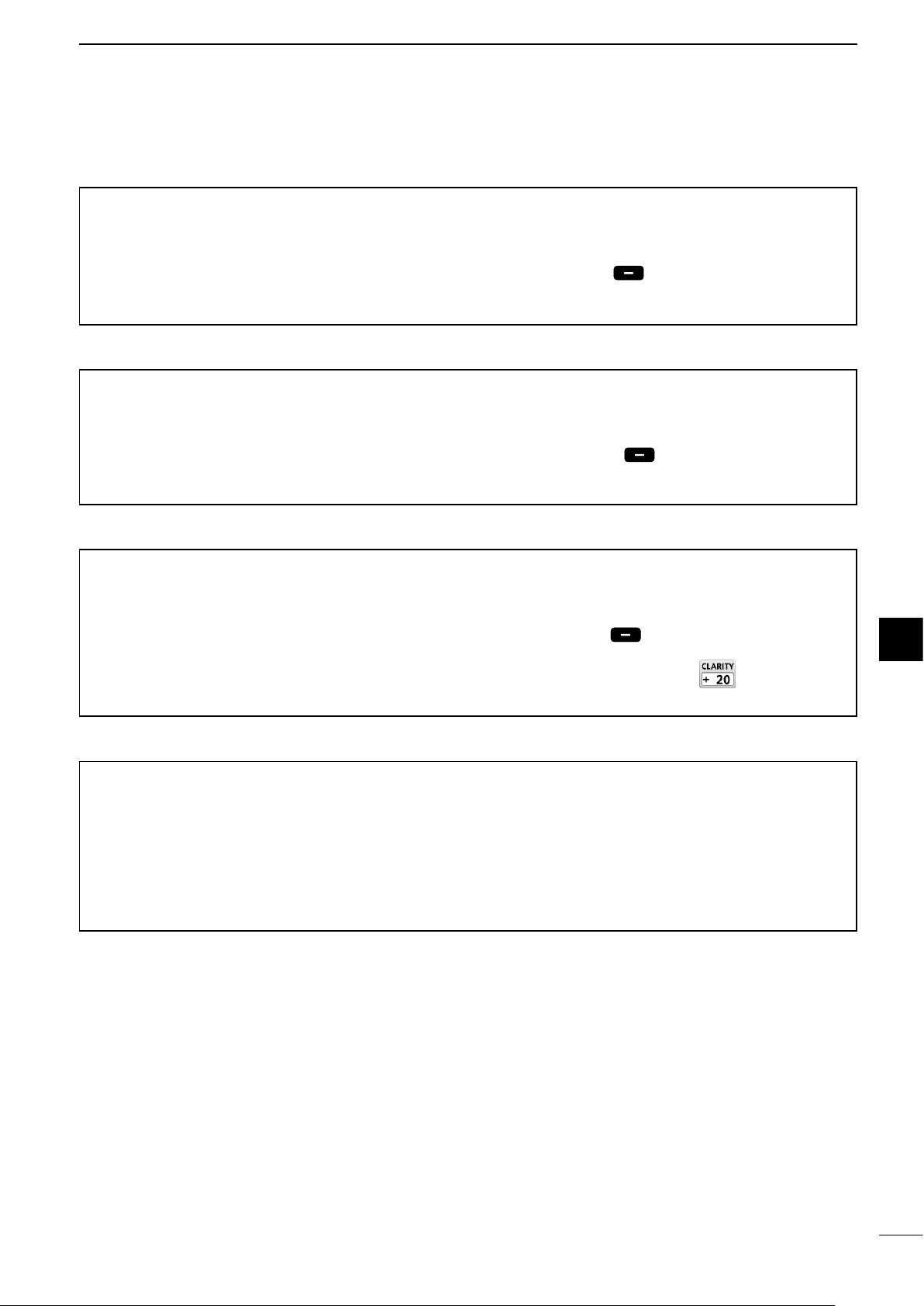
■ Setting a temporary operating frequency
You can temporarily change the operating frequency
of the selected channel. The frequency returns to the
preset value after you select another channel, or turn
OFF the transceiver.
1. Select a channel that is programmed near the
frequency you want to receive.
2. Push [RX/TX] to select the RX mode.
• The RX icon lights blue.
lights
3. Enter an RX frequency, then push [ENT].
Push
+
Rotate
5. Enter a TX frequency, then push [ENT].
Push
+
Rotate
CH/GRP
to select
a character
NOTE: Quickly enter a temporary operating TX
frequency and push [ENT]. Otherwise, it automatically
returns to the preset value soon.
NOTE:
• If you enter a frequency that is out of the frequency
range, an error beep sounds and it automatically returns
to the preset value.
• BE SURE to push [ENT] after entering a frequency.
Otherwise, it automatically returns to the preset value
after 2 seconds.
NOTE: Quickly enter a temporary operating RX
frequency and push [ENT]. Otherwise, it automatically
returns to the preset value soon.
4. Push [RX/TX] to select the TX mode.
• The TX icon lights blue.
CH/GRP
to select
a character
lights
17
Page 23
OTHER FUNCTIONS AND OPERATIONS
CH/GRP
CH/GRP
CH/GRP
CH/GRP
Push
+
Rotate
to select
a character
CH/GRP
CH/GRP
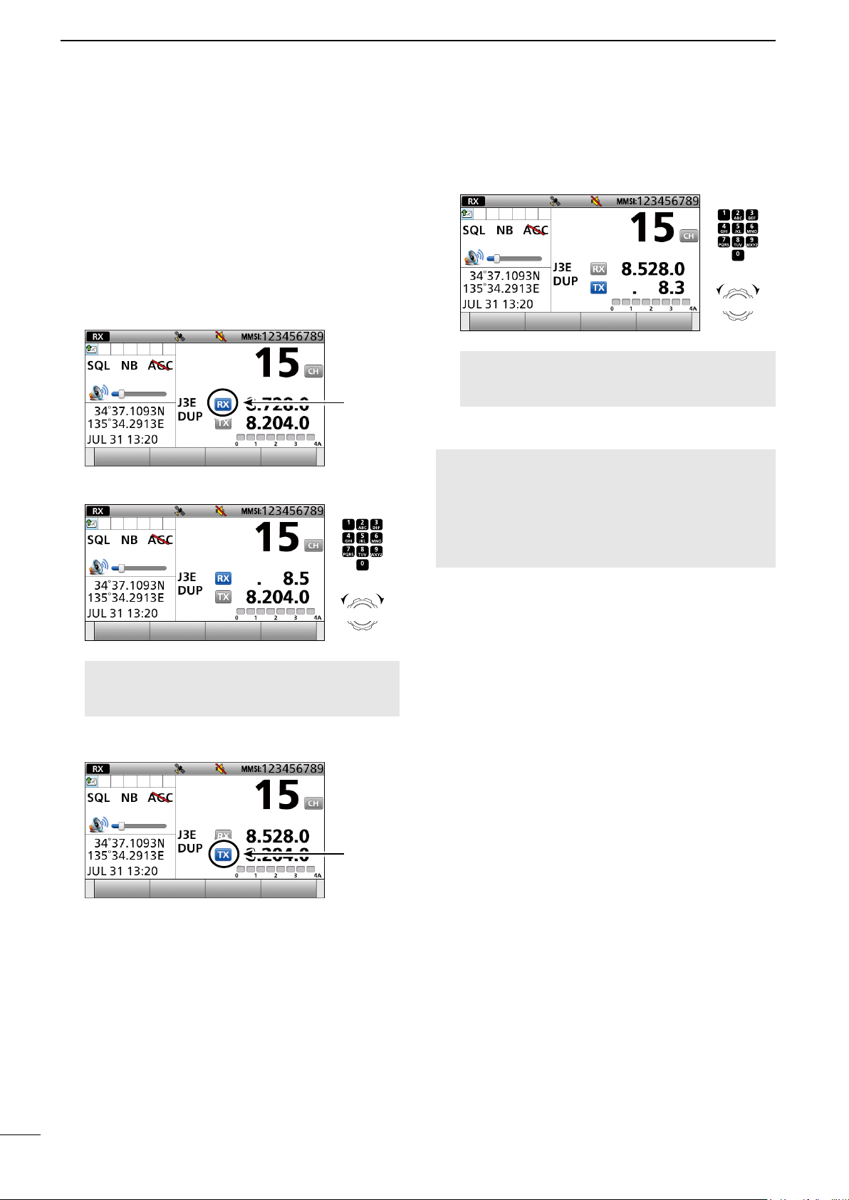
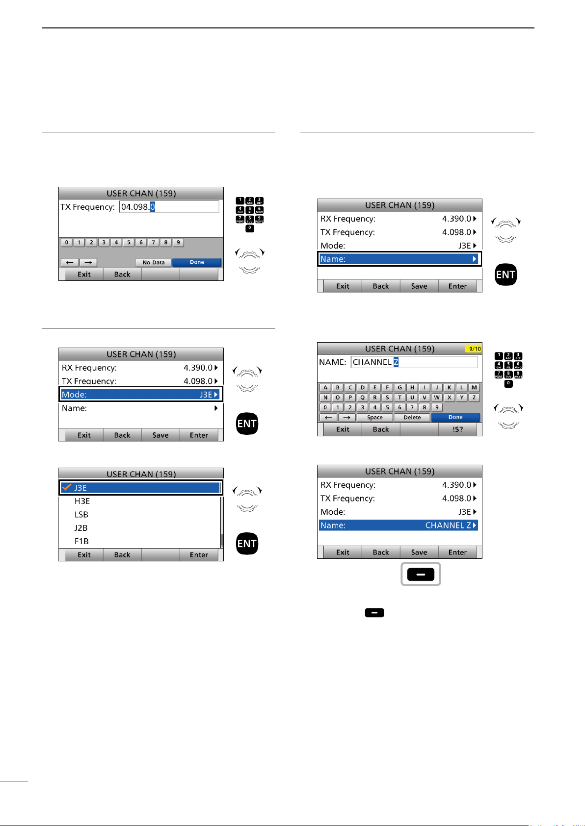
■ Setting a User channel or an ITU Simplex channel
6
Your dealer has already preset User channels and
ITU Simplex channels.
Follow the instructions as described below, only when
you need to edit the channels.
You can edit the following information of a User
channel or an ITU Simplex channel.
• Operating frequency
• Operating mode
• Channel name
1. Entering the Channel Edit screen
1. Push [MENU].
2. Select “Radio Settings.”
Rotate
+
Push
3. Select “User CHAN” or “ITU Simplex CHAN.”
(Example: User CHAN)”
Rotate
+
Push
NOTE:
• If you edit the preset channels, you may not be able to
communicate with other ships.
• The following instructions are for a User channel
Editing. However, you can set an ITU Simplex channel
name in the same way.
2. Setting an RX and TX operating frequencies
NOTE: The RX and TX operating frequency are the
same when you select an ITU Simplex channel.
5. Select “RX frequency.”
Rotate
+
Push
6. Enter an RX frequency.
After entering, push [▲], [▼], [◄], or [►] to select
“Done” and push [ENT].
(Example: 4.390.0)
Quick Reference
1
2
3
4
5
6
7
8
9
4. Select a channel you want to edit and push
[Edit] . (Example: CH 159)
Push
Rotate
7. Select “TX frequency.”
Rotate
+
Push
10
11
12
13
14
15
16
17
18
Page 24
6
CH/GRP
CH/GRP
CH/GRP
OTHER FUNCTIONS AND OPERATIONS
■ Setting a User channel or an ITU Simplex channel
2. Setting an RX and TX operating frequencies (continued)
8. Enter a TX frequency.
After entering, push [▲], [▼], [◄], or [►] to select
“Done” and push [ENT]. (Example: 4.098.0)
Rotate
CH/GRP
to select
a character
3. Setting an operating mode
9. Select “Mode.”
Rotate
Push
10. Select an operating mode. (Example: J3E)
Push
+
+
4. Setting a channel name
You can set a channel name of up to 10 characters
for each User and ITU channel. This may be helpful
to indicate the frequency's use, or a ship's name.
11. Select “Name.”
Rotate
+
Push
12. Enter a channel name.
After entering, push [▲], [▼], [◄], or [►] to select
“Done” and push [ENT].
Push
+
Rotate
CH/GRP
to select
a character
13. Push [Save].
Rotate
+
Push
• “Are you sure ?” is displayed.
Push
14. Push [OK] to save the name.
15. Push [MENU] to return to the Main screen.
19
Page 25
CH/GRP
CH/GRP
CH/GRP
CH/GRP
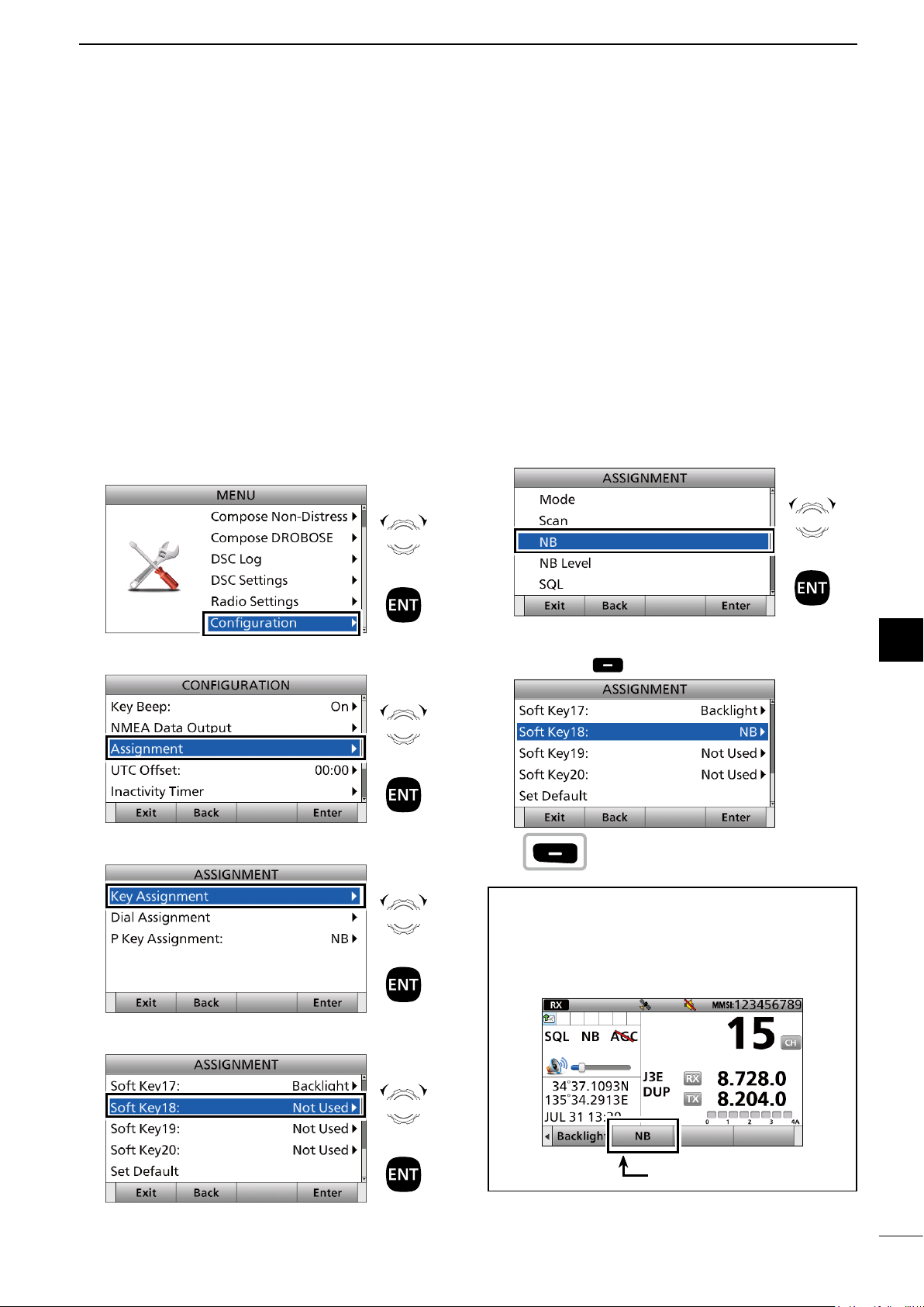
■ Assigning a function
microphone�
CH/GRP
You can assign some different Software Key functions
to a key between Soft Key 5 and Soft Key 20. (p. 5)
You can also assign some Software Key functions to
[VOL] on the controller and [P] on the optional
HM-214H
D Assigning a Software Key function to a
Software Key
Example: Assigning “NB” to “Soft Key 18.”
1. Push [MENU].
2. Select “Configuration.”
Rotate
OTHER FUNCTIONS AND OPERATIONS
6. Select a Software Key function. (Example: NB)
Rotate
6
Quick Reference
Quick Reference
1
2
2
3
3
3. Select “Assignment.”
4. Select “Key Assignment.”
+
Push
Rotate
+
Push
Rotate
+
Push
+
Push
• “NB” is assigned to “Soft Key 18.”
7. Push [Exit] to return to the Main screen.
TIP: You can con rm “NB” is assigned to a Software
Key after returning to the Main screen.
Push [Ω] or [≈] to the Soft Key 18's place.
• “NB” is displayed in the Software Key area.
Push
4
4
5
5
6
6
7
7
8
8
9
9
10
10
11
11
12
12
13
13
5. Select a place. (Example: Soft Key 18)
Rotate
+
Push
14
14
15
15
16
16
NB is assigned.
20
17
17
Page 26
6
CH/GRP
CH/GRP
CH/GRP
CH/GRP
CH/GRP
OTHER FUNCTIONS AND OPERATIONS
■ Assigning a function
D Assigning a Software Key function to
[VOL]
Example: Assigning “Backlight” to “Push ×3.”
1. Push [MENU].
2. Select “Configuration.”
3. Select “Assignment.”
4. Select “Dial Assignment.”
Rotate
+
Push
Rotate
+
Push
Rotate
6. Select a Software Key function.
(Example: Backlight)
Rotate
+
Push
• “Backlight” is assigned to “Push ×3.”
7. Push [Exit] to return to the Main screen.
Push
5. Select a place. (Example: Push ×3)
+
Push
Rotate
+
Push
TIP: You can con rm “Backlight” is assigned to
“Push ×3” after returning to the Main screen.
Push [VOL] 3 times.
• Backlight setting window is displayed.
21
Page 27
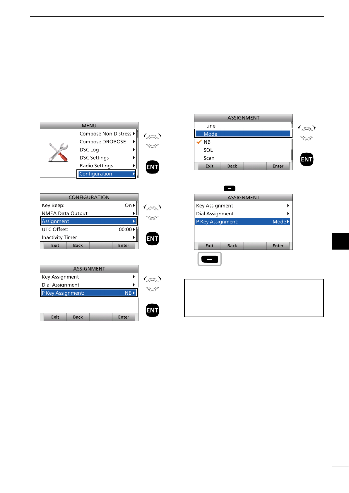
D Assigning a Software Key function to
MICROPHONE
CH/GRP
CH/GRP
CH/GRP
microphone
CH/GRP
[P] on the HM-214H
Example: Assigning “Mode” to [P].
OTHER FUNCTIONS AND OPERATIONS
6
1. Push [MENU].
2. Select “Configuration.”
3. Select “Assignment.”
4. Select “P Key Assignment.”
Rotate
+
Push
Rotate
+
Push
Rotate
+
Push
5. Select a Software Key function. (Example: Mode)
Rotate
+
Push
• “Mode” is assigned to [P].
6. Push [Exit] to return to the Main screen.
TIP: You can con rm “Mode” is assigned to [P] after
returning to the Main screen.
Push [P] on the HM-214H
• The operating mode changes.
Push
.
Quick Reference
1
2
3
4
5
6
7
8
9
10
11
12
13
14
15
16
17
22
Page 28
7
CH/GRP
CH/GRP
CH/GRP
CH/GRP
DSC OPERATION
■ DSC adress ID
You can enter a total of 100 DSC address IDs, and
assign a name of up to 10 characters to each ID.
InformationL
Rotate
Push : Push [ENT] to enter or set.
Push : Push the keypad to enter digits or
CH/GRP
: Rotate [CH/GRP] to select.
text.
D Entering an Individual ID
1. Push [MENU].
2. Select “DSC Settings.”
Rotate
+
Push
TIP: You can use the following key operations in the
Menu screen.
ACTION OPERATION
Select Rotate [CH/GRP]
Push [Ù] or [Ú]
Enter
Cancel Push [CLR]
Exit
5. Select “Address.”
Push [ENT], [CH/GRP],
or [Enter]
Push [Exit]
Rotate
+
Push
3. Select “Individual ID.”
4. Push [Add] .
Push
Rotate
+
Push
6. Enter a 9 digit Individual ID.
After entering, push [▲], [▼], [◄], or [►] to select
“Done” and push [ENT].
CH/GRP
to select
a character
L The rst digit is speci ed as ‘0’ for a Group ID.
L The rst 2 digits are ‘0’ for any Coast station ID.
7. Select “Call Frequency.”
Push
+
Rotate
Rotate
+
Push
23
Page 29
DSC OPERATION
CH/GRP
7
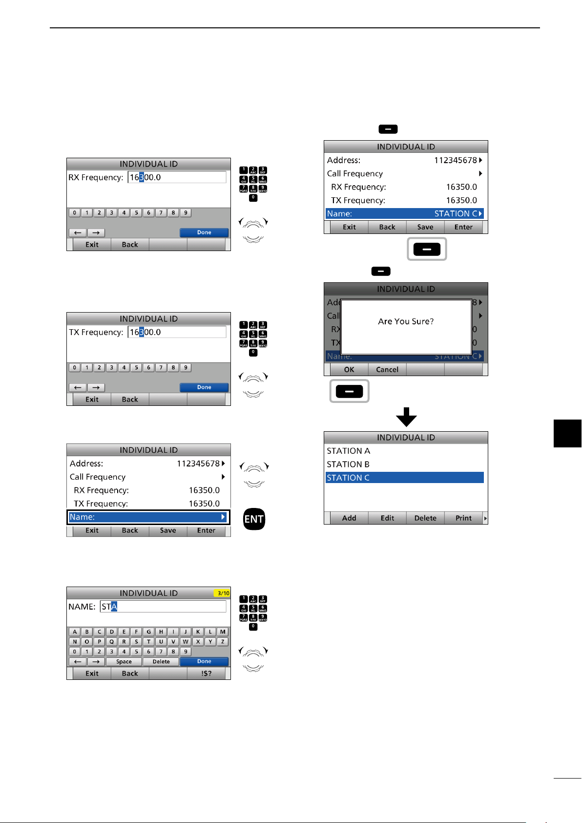
8. Enter an RX frequency.
After entering, push [▲], [▼], [◄], or [►] to select
“Done” and push [ENT].
CH/GRP
to select
a character
9. Enter a TX frequency.
After entering, push [▲], [▼], [◄], or [►] to select
“Done” and push [ENT].
CH/GRP
to select
a character
Push
+
Rotate
Push
+
Rotate
12. Push [Save] .
13. Push [OK] to save the ID.
Push
Push
Quick Reference
Quick Reference
1
1
2
2
3
4
5
5
6
6
10. Select “Name.”
11. Enter an Individual ID name.
After entering, push [▲], [▼], [◄], or [►] to select
“Done” and push [ENT].
CH/GRP
to select
a character
Rotate
+
Push
Push
+
Rotate
• The entered Individual ID is added to the ID list.
14. Push [MENU] to return to the Main screen.
7
7
8
8
9
9
10
10
11
11
12
12
13
13
14
14
15
15
16
16
24
17
17
Page 30
7
CH/GRP
CH/GRP
CH/GRP
CH/GRP
DSC OPERATION
■ DSC adress ID
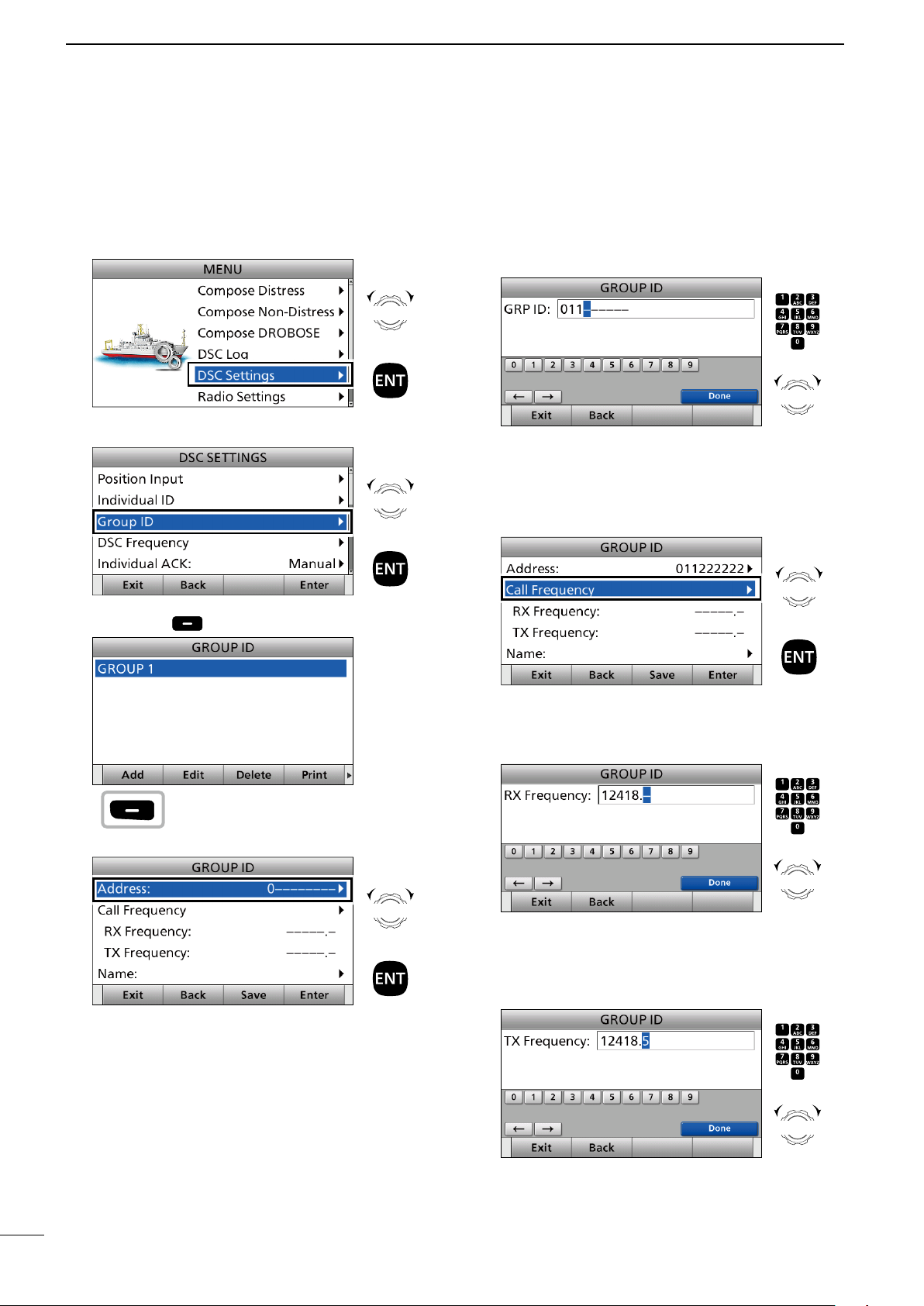
D Entering a Group ID
1. Push [MENU].
2. Select “DSC Settings.”
3. Select “Group ID.”
4. Push [Add] .
Rotate
+
Push
Rotate
+
Push
6. Enter a 9 digit Group ID.
After entering, push [▲], [▼], [◄], or [►] to select
“Done” and push [ENT].
CH/GRP
to select
a character
L The rst digit is speci ed as ‘0’ for a Group ID.
L The rst 2 digits are ‘0’ for any Coast station ID.
7. Select “Call Frequency.”
Push
+
Rotate
Rotate
+
Push
Push
5. Select “Address.”
Rotate
+
Push
8. Enter an RX frequency.
After entering, push [▲], [▼], [◄], or [►] to select
“Done” and push [ENT].
CH/GRP
to select
a character
9. Enter a TX frequency.
After entering, push [▲], [▼], [◄], or [►] to select
“Done” and push [ENT].
CH/GRP
to select
a character
Push
+
Rotate
Push
+
Rotate
25
Page 31

DSC OPERATION
CH/GRP
7
10. Select “Name.”
11. Enter a Group ID name.
After entering, push [▲], [▼], [◄], or [►] to select
“Done” and push [ENT].
CH/GRP
to select
a character
12. Push [Save] .
Rotate
+
Push
Push
+
Rotate
D Deleting an entered ID
1. Push [MENU].
• “MENU” screen is displayed.
2. Rotate [CH/GRP] to select “DSC Settings.”
• “DSC SETTING” screen is displayed.
3. Select “Individual ID” or “Group ID.”
• “INDIVIDUAL ID” or “GROUP ID” screen is displayed.
4. Rotate [CH/GRP] to select the ID to delete.
5. Push [Delete] .
Push
6. Push [OK] .
Quick Reference
1
2
3
4
5
13. Push [OK] to save the ID.
Push
Push
• The selected ID is deleted from the ID list.
7. Push [MENU] to return to the Main screen.
Push
6
7
8
9
10
11
12
13
14
15
16
17
• The entered Group ID is added to the ID list.
14. Push [MENU] to return to the Main screen.
26
Page 32

7
CH/GRP
CH/GRP
CH/GRP
CH/GRP
DSC OPERATION
■ Entering position data and time
A Distress call should include the ship’s position
data and time. If a GPS receiver compatible with the
IEC61162-1 Ed.4 (2010-11) format is connected,
position and UTC time are automatically included. If
no GPS is connected, you should manually enter your
position data and UTC (Universal Time Coordinated)
time.
NOTE:
• Manual entry is invalid when a GPS receiver is
connected.
• Manually entered position data and time are valid for
only 23.5 hours.
1. Push [MENU].
2. Select “DSC Settings.”
Rotate
Push
Set ‘N’ (North) or ‘S’ (South)
(any key)
L To select ʻNʼ (North latitude) or ʻSʼ (South latitude),
push any key when the cursor is on the ‘N’ or ‘S’
position.
5. After entering, push [▲], [▼], [◄], or [►] to select
“Done” and push [ENT].
6. Enter your longitude.
Push
3. Select “Position Input.”
4. Enter your latitude.
Enter
+
Push
Rotate
+
Push
Push
Enter
Rotate
Cursor moves
Push
Set ‘W’ (West) or ‘E’ (East)
(any key)
27
Cursor moves
Rotate
7. After entering, push [▲], [▼], [◄], or [►] to select
“Done” and push [ENT].
Page 33

DSC OPERATION
CH/GRP
7
8. Enter your UTC time.
Enter
Cursor moves
TIP:
Push
When position data and time are set, Latitude,
Longitude and UTC Time are displayed.
Quick Reference
Rotate
• Latitude: 34°37.1093N
• Longitude: 135°34.2913E
• UTC Time: 13:20
When no position data and time are set, “No
Position” and “No Time” are displayed.
1
2
3
4
5
Push
6
9. After entering, push [▲], [▼], [◄], or [►] to select
“Done” and push [ENT].
• The DSC setting screen is displayed.
10. Push [MENU] to return to the Main screen.
InformationL
While entering:
• To move the cursor:
Rotate [CH/GRP].
• To correct the entry:
Move the cursor to the character. And then, enter the
correct character.
• To clear the entry:
Push [Ù], [Ú], [Ω], or [≈] to select “No Data.” And then
push [ENT].
When the following screen is displayed, push [ENT].
• To return to the Main screen:
Push [Exit]
• To go back to the previous screen:
Push [Back]
.
.
7
8
9
10
11
12
13
14
15
16
17
28
Page 34

7
DSC OPERATION
■ DSC Task mode
After sending or receiving the DSC call, the
transceiver enters the DSC Task mode.
(Example: After receiving a Geographical call)
In the DSC Task mode, you can resend the call, or
send an acknowledgement to the caller station.
• The transceiver can hold up to 7 DSC tasks.
• In the Standby mode, a task icon is displayed in the Task
area, when the transceiver has a DSC task. (p. 6)
• When any DSC task icon is displayed in the Standby
mode, you can enter the DSC Task mode by pushing
[Task Mode]
NOTE: The DSC Task mode has the Time-out Timer
(TOT) function. When you push no key for a preset
period, the transceiver automatically cancels the
DSC Task mode.
The count down alarm sounds 10 seconds before
the TOT activates.
No count down alarm sounds before Radio
Telephone TOT activates.
The default settings of the TOT function:
• DSC Related: 15 minutes
• Distress Related: OFF
.
D About “Active” and “Hold”
The DSC Task mode has 2 statuses, “Active” and
“Hold.” When you send the repeat call, or send an
acknowledgement to the caller station, push
[Active] to display the Active window.
• Active window
• Hold window
L To view the contents, push [Ù] or [Ú].
D Software Key functions
While in the DSC Task mode, the following functions
are displayed rst.
FUNCTION DESCRIPTION
Hold Push to cancel the Active Task
window.
Active Push to activate the selected Task
window.
Next Task Push to select other Task window.
DEL Task Push to delete the Task window.
Standby
Mode
The following functions may be displayed, depending
on the call type.
FUNCTION DESCRIPTION
Cancel Push to send a Cancel call.
Resend Push to resend the call.
Pause Push to pause the Call Repeat
Finish Push to return to the Main screen.
ACK Push to send an acknowledgement.
History Push to display the Distress call
Relay Push to send a Distress Relay call.
Push to enter the Standby mode.
function.
history screen.
L “✔” is displayed on the active Task tab.
L To view the contents, rotate [CH/GRP].
29
See the following pages for details of the DSC Task
mode operation for each DSC call.
Page 35

■ Sending a Distress call
NOTE: NEVER make a Distress call if your ship or a
person is not in an emergency.
A Distress call should be made only when
immediate help is needed.
You should send a Distress call if, in the opinion of
the Master, the ship or a person is in distress and
requires immediate assistance.
One of the Emergency frequencies is automatically
selected to send a Distress call.
DSC OPERATION
7
Quick Reference
1
D Simple call
1. Confirm no Distress call is being received.
2. Lift up the key cover, then hold down [DISTRESS]
until “Transmitting” is displayed to send a Distress
call.
3. After sending, “Waiting for ACK” is displayed.
4. When receiving the acknowledgement:
• Alarm sounds.
• The following screen is displayed.
Push any [Alarm Off] .
5. Push any [Close Call RCVD Window] .
Push
any
6. Hold down [PTT] to announce your situation.
7. Push [Standby Mode] to return to the
Standby mode.
NOTE:
A Distress alert default contains:
- Nature of distress:
Undesignated distress
- Position data:
The latest GPS or manual input data is held for
23.5 hours, or until turning OFF the transceiver.
2
3
4
5
6
7
8
9
10
11
12
13
14
15
Push
any
16
17
30
Page 36

7
CH/GRP
CH/GRP
CH/GRP
CH/GRP
DSC OPERATION
■ Sending a Distress call
D Regular call
1. Push [Compose Distress] to display the
COMPOSE DISTRESS screen.
Push
Step.1 Setting a “Nature of Distress”
2. Select “Nature of Distress.”
Rotate
+
Push
Step 3. Setting a communication frequency
6. Select “Attempt.”
Rotate
+
Push
7. Select an option.
(Example: Multi Frequency)
Rotate
+
Push
3. Select an option.
(Example: Fire, Explosion)
Rotate
+
Push
The transceiver stores this setting for 30 seconds.
Step 2. Entering a “Position”
NOTE: You can skip this step if your position data
and time are valid. In that case, go to Step 3.
Step 4. Sending
8. Lift up the key cover, then hold down [DISTRESS]
until “Transmitting” is displayed to send the
Distress call.
• While holding down [DISTRESS], count down beeps
sound and both the key and display backlighting
blink.
31
4. Select “Position.”
• The Latitude Position Entry screen is displayed.
5. Enter your position data and time.
• See page 27 for entering details.
Page 37

DSC OPERATION
7
NOTE: To cancel a Distress call while
transmitting see page 34.
9. After sending, the following screen is displayed.
Step. 5 Replying
10. When receiving the acknowledgement:
• Alarms sound.
• The following screen is displayed.
Push any [Alarm Off] .
Push
any
11. Push any [Close Call RCVD Window] .
NOTE:
Transmitting:
• A Distress call default contains:
- Nature of distress:
Undesignated distress
- Position data:
The latest GPS or manual input position data is
retained for 23.5 hours, unless you turn OFF the
transceiver.
• While holding down [DISTRESS], count down beeps
sound, and both the key and display backlights blink.
• The Distress call is transmitted in one of the DSC
Emergency frequencies.
Waiting for an Acknowledgement:
• The Distress call is automatically transmitted every 3.5
to 4.5 minutes, until an acknowledgement is received
(Call Repeat function), or you make a Distress Cancel
call. (p. 35)
• To manually transmit a Distress repeat call, push
[Resend]
• To display the transmitted Distress call information, push
[∫] or [√].
• To pause the Call Repeat function,
push [Pause]
To resume it, push [Resume Countdown].
.
.
Quick Reference
1
2
3
4
5
6
7
8
9
Push
any
12. Hold down [PTT] to announce your situation.
13. Push [Standby Mode] to return to the
Standby mode.
10
11
12
13
14
15
16
17
32
Page 38

7
DSC OPERATION
■ Sending a Distress call
D Resending a Distress call
While waiting for an acknowledgement, you can
resend the call (Repeat call).
1. When “Waiting for ACK” is displayed, push
[Resend] .
Push
See page 29 for details of the Software Key
functions in the DSC Task mode.
2. Lift up the key cover, then hold down [DISTRESS]
until “Retransmitting” is displayed to resend the
call.
• While holding down [DISTRESS], count down beeps
sound and both the key and display backlighting
blink.
3. When receiving the acknowledgement:
• Alarms sound.
• The following screen is displayed.
Push any [Alarm Off] .
Push
any
4. Push any [Close Call RCVD Window] .
NOTE: To cancel a Distress call while
transmitting see page 34.
Push
any
5. Hold down [PTT] to announce your situation.
6. Push [Standby Mode] to return to the
Standby mode.
33
Page 39

D Sending a Distress Cancel call
CH/GRP
You can send the Distress Cancel call while
transmitting a Distress call or while waiting for a
Distress Acknowledgement.
While transmitting a Distress call:
1. While transmitting a Distress call push
[Cancel]
.
DSC OPERATION
3. After sending, the following screen is displayed.
Push [Select FREQ] .
7
Push
2. Confirm the content and push [Continue] .
The frequencies that you have to send voice cancel
messages are displayed.
(Example: 2/4/8/12/16 MHz)
Push
To cancel the Distress Cancel call, push [Back]
.
4. Select a frequency to send a voice cancel
message and push [ENT].
The check mark shows that the Distress call on the
selected frequency is canceled by sending voice
cancel message.
5. Hold down [PTT] to announce your situation.
You can conrm the statement of the Distress
Cancel call by rotating [CH/GRP].
6. Repeat steps 3 to 5 to cancel for all frequencies.
7. After sending a voice cancel message for all
frequencies, [Finish] is displayed.
Push [Finish] .
Push
Rotate
+
Push
Quick Reference
1
2
3
4
5
6
7
8
9
10
11
12
Push
13
8. Push [Standby Mode] to return to the Main
screen.
14
15
16
17
► Continued on the next page.
Push
34
Page 40

7
CH/GRP
DSC OPERATION
■ Sending a Distress call
D Sending a Distress Cancel call (continued)
While waiting for a Distress Acknowledgement:
1. When “Waiting for ACK” is displayed, push
[Cancel]
See page 29 for details of the Software Key
functions in the DSC Task mode.
.
Push
2. Push [Continue] to send the Distress Cancel
call.
4. Select a frequency to send a voice cancel
message and push [ENT].
The check mark shows that the Distress call on the
selected frequency is canceled by sending voice
cancel message.
Rotate
+
Push
5. Hold down [PTT] to announce your situation.
You can conrm the statement of the Distress
Cancel call by rotating [CH/GRP].
6. Repeat steps 3 to 5 to cancel for all frequencies.
7. After sending a voice cancel message for all
frequencies, [Finish] is displayed.
Push [Finish] .
Push
3. After sending, the following screen is displayed.
Push [Select FREQ] .
Push
Push
8. Push [Standby Mode] to return to the Main
screen.
Push
35
Page 41

D Sending a Distress acknowledgement
DSC OPERATION
7
Distress call reception should stop after one
sequence because the coast station should send
back an ‘acknowledgement’ to the ship.
If the distress call continues even the coast station
send back an ‘acknowledgement,’ the ship in distress
may not be receiving the call.
In such cases, you should contact the coast station
via the phone and send back an ‘acknowledgement’
on behalf of the coast station if the coast station
requires.
IMPORTANT: Distress acknowledgements should
be transmitted only on the 2187.5 kHz, according
to regulations (ITU-R 493-13). When you receive
a Distress call on other frequency bands, [ACK
(Distress)] is not displayed in the software key area.
Quick ACK:
1. When a Distress call is received:
• Alarm sounds.
• The following screen is displayed.
Push any [Alarm Off] .
4. Push [ACK (Distress)]
5. Push [OK] .
Push
Push
.
Quick Reference
1
2
3
4
5
6
2. Push [Accept] .
• Enters the DSC Task mode.
3. Push [►] to scroll the software key functions.
Push
any
Push
• The DSC call contents screen is displayed.
Rotate [CH/ENT] to view the call contents.
6. Push [Call] to send a Distress
acknowledgement.
► Continued on the next page.
7
8
9
10
11
Push
12
13
14
15
16
17
36
Page 42

7
CH/GRP
DSC OPERATION
■ Sending a Distress call
D Sending a Distress acknowledgement (continued)
7. After sending, the following screen is displayed.
8. Hold down [PTT] to communicate with the ship in
distress.
9. Push [Standby Mode] to return to the
Standby mode.
TIP: When you push [Pause] in step 2, the
countdown will be paused. Push [Resume] to
restart the countdown.
D Sending a Distress Relay call
There are 2 ways to transmit the distress relay call—
“DROBOSE (Distress Relay On Behalf Of Someone
Else)” and “Distress Relay Call with Distress Call Log”.
NOTE: DO NOT push [DISTRESS] to transmit
a distress relay call. It is used for only your own
distress calls.
To transmit the Distress Relay call with
“ DROBOSE”:
You may transmit a Distress Relay call when a ship
in distress is in a situation where the Distress call
cannot be transmitted, or when you nd a ship in
distress and quick help is needed.
Distress Relay Transmission
Your ship
Coast Station
Ship in Distress
No Distress
Transmission
1. Push [Compose DROBOSE] .
To display the screen from the Menu screen:
([MENU] >
Compose DROBOSE)
Push
2. Select “Message Type.”
Rotate
+
Push
37
Page 43

DSC OPERATION
CH/GRP
CH/GRP
CH/GRP
CH/GRP
CH/GRP
Push
+
Rotate
to select
a character
CH/GRP
CH/GRP
CH/GRP
7
3. Select a message type.
(Example: Individual)
Rotate
+
Push
4. Select “Address.”
Rotate
+
Push
5. Select a coast station address or “Manual Input.”
(Example: COAST A)
Rotate
7. Select “Manual Input.”
Rotate
+
Push
NOTE: Distress Call Log is displayed after receiving
the Distress call.
IDs for DROBOSE.
8. Enter the 9 digit Distress ID (MMSI ID) code of
the ship in distress that you want to help.
After entering, select “Done” and push [ENT].
9. Select “Nature of Distress.”
DO NOT select displayed Individual
Quick Reference
1
2
3
4
5
6
7
NOTE: When you select “Manual Input” in
this step, push the keypad to manually enter an
Individual ID.
6. Select “Distress ID.”
+
Push
Rotate
+
Push
10. Select an option.
(Example: Fire, Explosion)
The transceiver stores this setting for 30 seconds.
► Continued on the next page.
Rotate
+
Push
Rotate
+
Push
8
9
10
11
12
13
14
15
16
17
38
Page 44

7
CH/GRP
CH/GRP
CH/GRP
DSC OPERATION
■ Sending a Distress call
D Sending a Distress Relay call (continued)
11. Select “Position.”
Rotate
+
Push
• The Latitude Position Entry screen is displayed.
• Your position data and time are displayed.
12. Enter the position data and time of the ship in
distress.
After entering, select “Done” and push [ENT].
See page 27 for position entering details.
13. Select “Call Frequency.”
Rotate
+
Push
15. Push [Call] to send the Distress Relay call.
Push
16. After sending, the following screen is displayed.
14. Select an option.
(Example: 2187.5 kHz)
Rotate
+
Push
See page 29 for details of the software key function
in the DSC Task mode.
17. Hold down [PTT] to communicate with a maritime
station.
18. Push [Standby Mode] to return to the
Standby mode.
39
Page 45

DSC OPERATION
CH/GRP
CH/GRP
CH/GRP
CH/GRP
CH/GRP
CH/GRP
7
To transmit the Distress Relay call with
“Distress Call Log”:
You can relay a distress call after receiving the
distress call.
Distress Relay Transmission
Coast
Your ship
Distress Transmission
Ship in Distress
1. Push [Compose DROBOSE] .
Station
Push
4. Select “Address.”
Rotate
+
Push
5. Select a coast station address or “Manual Input.”
(Example: COAST A)
Rotate
+
Push
NOTE: When you select “Manual Input” in
this step, push the keypad to manually enter an
Individual ID.
6. Select “Distress ID.”
Rotate
Quick Reference
1
2
3
4
5
6
7
2. Select “Message Type.”
3. Select a message type.
(Example: Individual)
Rotate
+
Push
Rotate
+
Push
7. Select a Distress ID from the list.
Distress Call Log is displayed after receiving the
Distress Call.
► Continued on the next page.
+
Push
Rotate
+
Push
8
9
10
11
12
13
14
15
16
17
40
Page 46

7
CH/GRP
CH/GRP
DSC OPERATION
■ Sending a Distress call
D Sending a Distress Relay call (continued)
8. Select “Call Frequency.”
Rotate
+
Push
9. Select an option.
(Example: 2187.5 kHz)
Rotate
+
Push
10. Push [Call] to send the Distress Relay call.
11. After sending, the following screen is displayed.
See page 29 for details of the software key function
in the DSC Task mode.
12. Hold down [PTT] to communicate with a coast
station.
13. Push [Standby Mode] to return to the
Standby mode.
41
Push
Page 47

D Sending a Distress Relay
acknowledgement
DSC OPERATION
7
Only when the Distress Relay call is received, you
can send the Distress Relay acknowledgement.
Quick ACK:
1. When a Distress Relay call is received:
• Alarm sounds.
• The following screen is displayed.
Push any [Alarm Off] .
Push
any
2. Push [Accept] .
• Enters the DSC Task mode.
• “✔” is displayed on the Task tab.
5. Push [Call] to send the Distress Relay
acknowledgement.
6. After sending, the following screen is displayed.
7. Hold down [PTT] to communicate with the ship in
distress.
8. Push [Standby Mode] to return to the
Standby mode.
Push
Quick Reference
1
2
3
4
5
6
7
8
3. Push [≈] to scroll the software key function.
4. Push [ACK (Relay)] .
• The call contents screen is displayed.
• The call contents screen is displayed.
Rotate [CH/ENT] to view the call contents.
Push
Push
TIP: When you push [Pause] in step 2, the
countdown will be paused. Push [Resume] to
restart the countdown.
9
10
11
12
13
14
15
16
17
42
Page 48

7
CH/GRP
CH/GRP
CH/GRP
CH/GRP
CH/GRP
CH/GRP
DSC OPERATION
■ Sending a Non-Distress calls
D Sending an Individual call
The Individual call function enables you to transmit
a DSC signal to only a speci c coast station or ship.
After transmission, wait for an acknowledgement from
the receiving station.
You can communicate by voice after receiving the
acknowledgement ‘ACK (able).’
1. Push [Compose Non-Distress] .
To display the screen from the Menu screen:
([MENU] >
Compose Non-Distress)
Push
2. Select “Address.”
Rotate
+
Push
4. Select “Category.”
Rotate
+
Push
5. Select an option.
(Example: Routine)
Rotate
+
Push
Information
When you have manually entered an Individual ID,
push the keypad to select the DSC call frequency.
1. Select “Call Frequency.”
Rotate
43
3. Select an Individual address, or “Manual Input.”
(Example: STATION A)
Rotate
+
Push
NOTE: When you select “Manual Input” in
this step, push the keypad to manually enter an
Individual ID.
2. Select a DSC call frequency, or “Manual Input.”
(Example: INTER2-1)
NOTE: When you select “Manual Input” in this
step, push the keypad to manually enter the DSC
call frequency.
+
Push
Rotate
+
Push
Page 49

DSC OPERATION
CH/GRP
CH/GRP
7
6. Select “Comm Frequency.”
Rotate
+
Push
7. Select a communication frequency, or “Manual
Input.”
(Example: SHIP 2M)
Rotate
+
Push
NOTE: When you select “Manual Input” in
this step, push the keypad to manually enter a
communication frequency.
10. When receiving the acknowledgement:
• Alarm sounds.
• The following window is displayed.
(Example: ACK (Able))
Push any [Alarm Off] .
11. Push any [Close Call RCVD Window] .
12. Hold down [PTT] to communicate.
13. Push [Standby Mode] to return to the
Standby mode.
Quick Reference
1
2
3
4
5
6
7
8. Send an Individual call.
9. After sending, “Waiting for ACK” is displayed.
Push
8
9
10
11
12
13
14
15
16
17
44
Page 50

7
CH/GRP
CH/GRP
CH/GRP
DSC OPERATION
■ Sending a Non-Distress calls
D
Sending an Individual acknowledgement
When receiving an Individual call, you can send an
acknowledgement (‘Able,’ ‘Unable,’ or ‘New CH’) by
using the on-screen prompts.
1. When an Individual call is received:
• Alarm sounds.
• The following screen is displayed.
Push any [Alarm Off] .
Push
2. Push [Accept] .
5. Rotate [CH/GRP] to confirm the contents.
6. Push [Call] to send the Individual
acknowledgement.
7. Hold down [PTT] to communicate.
8. Push [Exit] to return to the Main screen.
D Sending a Group call
You can transmit a DSC signal to only a speci c
group.
1. Push [Compose Non-Distress] .
To display the screen from the Menu screen:
([MENU] >
Compose Non-Distress)
2. Select “Message Type.”
Push
45
• Enters the DSC Task mode.
• “✔” is displayed on the Task tab.
Push
3. Push [≈] to scroll the software key function.
4. Push a key to select an acknowledgement option.
(Example: ACK (Able))
Push
Information
ACK (Able):
Send an acknowledgment without any changes.
ACK (Unable):
Send an acknowledgment, but you cannot make a
communication.
ACK (New CH):
Send an acknowledgment. You can specify the Voice
Communication channel.
• The call contents screen is displayed.
Rotate
+
Push
3. Select “Group.”
Rotate
+
Push
4. Select “Address.”
Rotate
+
Push
Page 51

DSC OPERATION
CH/GRP
CH/GRP
CH/GRP
CH/GRP
CH/GRP
7
5. Select a Group ID, or “Manual Input.”
(Example: GROUP 1)
Rotate
+
Push
NOTE: When you select “Manual Input” in this step,
push the keypad to manually enter a Group ID.
Information
• The “Category” is xed to “Routine.”
• When you have manually entered a Group ID, push the
keypad to manually select the DSC call frequency.
1.
Select “Call Frequency.”
Rotate
+
Push
7. Select a communication frequency, or “Manual
Input.”
(Example: SHIP 2M)
Rotate
+
Push
NOTE: When you select “Manual Input” in this
step, push the keypad to manually enter a
communication frequency.
8. Push [Call]
to send the Group call.
Quick Reference
1
2
3
4
5
6
2. Select a DSC call frequency, or “Manual Input.”
(Example: INTER2-1)
NOTE: When you select “Manual Input” in this
step, push the keypad to manually enter the DSC
call frequency.
6. Select “Comm Frequency.”
Rotate
+
Push
Rotate
+
Push
9. After sending, the following screen is displayed.
See page 29 for details of the software key functions
in the DSC Task mode.
10. Hold down [PTT] to communicate.
11. Push [Standby Mode] to return to the
Standby mode.
Push
7
8
9
10
11
12
13
14
15
16
17
46
Page 52

7
CH/GRP
CH/GRP
CH/GRP
CH/GRP
Push
+
Rotate
to select
a character
CH/GRP
Push
+
Rotate
to select
a character
CH/GRP
DSC OPERATION
■ Sending a Non-Distress calls
D Sending a Geographical call
Send a Geographical call when urgency or safety
message announcement is necessary to the ships in
the particular area.
1. Push [Compose Non-Distress] .
To display the screen from the Menu screen:
([MENU] >
Compose Non-Distress)
Push
2. Select “Message Type.”
Rotate
+
Push
5. Select “Circle” or “Quadrant.”
Rotate
+
Push
6. Enter the area information.
When selecting “Circle”:
You can send a Geographical call within the area
covered by a set nautical mile radius from your
position.
1 Enter the latitude of your position.
After entering, select “Done” and push [ENT].
Displays your ship's position as default.
3. Select “Geographical.”
4. Select “Area.”
Rotate
+
Push
Rotate
+
Push
2 Enter the longitude of your position.
After entering, select “Done” and push [ENT].
Displays your ship's position as default.
47
Page 53

DSC OPERATION
CH/GRP
CH/GRP
Push
+
Rotate
to select
a character
CH/GRP
Push
+
Rotate
to select
a character
CH/GRP
Push
+
Rotate
to select
a character
CH/GRP
Push
+
Rotate
to select
a character
CH/GRP
Push
+
Rotate
to select
a character
CH/GRP
7
3 Enter the radius of the Geographical call area.
After entering, select “Done” and push [ENT].
(Example: 500 nm)
When selecting “Quadrant”:
You can send a Geographical call within the square
area as shown below. Your position is the upper left
corner of the square.
• Example
Latitude: 20°N Behind You: 10°
Longitude: 100°W To Your Right: 20°
20˚N/100˚W
10˚N
100˚W
1 Enter the latitude of your position.
After entering, select “Done” and push [ENT].
20˚N
80˚W
10˚N
80˚W
3 Enter the height of the Geographical call area.
After entering, select “Done” and push [ENT].
4 Enter the width of the Geographical call area.
After entering, select “Done” and push [ENT].
7. Select “Category.”
The displayed items may differ depending on the
selected option in “Area.”
Rotate
+
Push
Quick Reference
1
2
3
4
5
6
7
8
9
10
2 Enter the longitude of your position.
After entering, select “Done” and push [ENT].
8. Select an option.
(Example: Safety)
Rotate
+
Push
► Continued on the next page.
11
12
13
14
15
16
17
48
Page 54

7
CH/GRP
CH/GRP
CH/GRP
CH/GRP
DSC OPERATION
■ Sending a Non-Distress calls
D Sending a Geographical call (continued)
9. Select “Call Frequency.”
13. Push [Call] to send the Geographical call.
Rotate
+
Push
10.
Select an option. (Example: 8414.5 kHz)
Rotate
+
Push
11. Select “Comm Frequency.”
Rotate
+
Push
12. Select a communication frequency, or “Manual
Input.”
(Example: SHIP 6M)
Push
14. After sending, the following screen is displayed.
See page 29 for details of the software key functions
in the DSC Task mode.
15. Hold down [PTT] to communicate.
16. Push [Standby Mode] to return to the
Standby mode.
49
Rotate
+
Push
NOTE: When you select “Manual Input” in this step,
push the keypad to manually enter a communication
frequency.
Page 55

D Sending a Position Request call
CH/GRP
CH/GRP
CH/GRP
CH/GRP
CH/GRP
CH/GRP
DSC OPERATION
7
Send a Position Request call when you want to know
a speci c ship’s current position, and so on.
1. Push [Compose Non-Distress] .
To display the screen from the Menu screen:
([MENU] >
2. Select “Message Type.”
Compose Non-Distress)
Push
Rotate
+
Push
5. Select an Individual ID, or “Manual Input.”
(Example: STATION A)
Rotate
NOTE: When you select “Manual Input” in
this step, push the keypad to manually enter an
Individual ID.
6. Select “Call Frequency.”
Rotate
7.
Select an option. (Example: 8414.5 kHz)
+
Push
+
Push
Quick Reference
1
2
3
4
5
6
7
3. Select “Position.”
4. Select “Address.”
Rotate
+
Push
Rotate
+
Push
8.
Push [Call] to send the Position Request call.
► Continued on the next page.
Push
Rotate
+
Push
8
9
10
11
12
13
14
15
16
17
50
Page 56

7
DSC OPERATION
■ Sending a Non-Distress calls
D Sending a Position Request call (continued)
9. After sending, the following screen is displayed.
• See page 29 for details of the software key function
in the DSC Task mode.
4. Push a key to select an acknowledgement option.
(Example: ACK (Able))
10. Push [Standby Mode] to return to the
Standby mode.
D Sending a Position Request
acknowledgement
When receiving a Position Request call, you can
send an acknowledgement.
1. When a Position Request call is received:
• Alarm sounds.
• The following screen is displayed.
Push any [Alarm Off] .
2. Push [Accept] .
Push
Information
ACK (Able):
Send an acknowledgment with position data and
time.
ACK (Unable):
Send an acknowledgment, but it does not include
position data.
• The call contents screen is displayed.
Rotate [CH/GRP] to conrm the contents.
Change your position data, if the displayed data is
invalid. (p. 27)
5. Push [Call] to send the Position Request
acknowledgement.
Push
• Enters the DSC Task mode.
• “✔” is displayed on the Task tab.
3. Push [≈] to scroll the software key function.
51
• Your position data and time are transmitted.
6. Push [Standby Mode] to return to the
Standby mode.
TIP: When “Position ACK” is set to Auto, the
transceiver automatically replies to the call.
(p. 71)
Push
Page 57

D Sending a Polling Request
CH/GRP
acknowledgement
DSC OPERATION
7
When a Polling Request is received, you can send an
acknowledgement.
1. When a Polling Request call is received:
• Alarm sounds.
• The following screen is displayed.
Push any [Alarm Off] .
Push
any
2. Push [Accept] .
5. Push [Call] to send the Polling Request
acknowledgement.
• Your position data and time are transmitted.
6. Push [Standby Mode] to return to the
Standby mode.
Push
D Sending a Test call
Testing on the exclusive DSC Distress and Safety
calling frequencies should be avoided as much as
possible by using other methods.
Normally the test call would require no further
communications between the 2 stations involved.
1. Push [Compose Non-Distress] .
Quick Reference
1
2
3
4
5
6
7
• Enters the DSC Task mode.
3. Push [≈] to scroll the software key function.
4. Push [ACK] .
• The call contents screen is displayed.
• Rotate [CH/GRP] to con rm the contents.
Push
Push
To display the screen from the Menu screen:
([MENU] >
2. Select “Message Type.”
Compose Non-Distress)
Push
► Continued on the next page.
Rotate
+
Push
8
9
10
11
12
13
14
15
16
17
52
Page 58

7
CH/GRP
CH/GRP
CH/GRP
CH/GRP
CH/GRP
DSC OPERATION
■ Sending a Non-Distress calls
D Sending a Test call (continued)
3. Select “Test.”
4. Select “Address.”
5. Select an Individual ID, or “Manual Input.”
(Example: STATION A)
Rotate
+
Push
Rotate
+
Push
Rotate
8. Push [Call] to send the Test call.
Push
9. After sending, the following screen is displayed.
See page 29 for details of the software key function
in the DSC Task mode.
10. Push [Standby Mode] to return to the
Standby mode.
NOTE: When you select “Manual Input” in
this step, push the keypad to manually enter an
Individual ID.
6. Select “Call Frequency.”
7.
Select an option. (Example: 8414.5 kHz)
+
Push
Rotate
+
Push
Rotate
D Sending a Test call acknowledgement
When a Test call is received, you can send an
acknowledgement.
1. When a Test call is received:
• Alarm sounds.
• The following screen is displayed.
Push any [Alarm Off] .
Push
any
53
+
Push
Page 59

DSC OPERATION
CH/GRP
CH/GRP
7
2. Push [Accept] .
• Enters the DSC Task mode.
3. Push [≈] to scroll the software key function.
4. Push [ACK] .
• The call contents screen is displayed.
• Rotate [CH/GRP] to con rm the contents.
5. Push [Call] to send the Test call
acknowledgement.
Push
Push
D Sending a Medical Transports call or
Ships and Aircraft call
The Medical Transports call informs all ships, by
urgency priority, that your ship is carrying a patient in
need of medical treatment.
The Ships and Aircraft call informs all ships that your
ship is a neutral (not a participant) in armed confl ict.
Be sure to send the call BEFORE entering an area of
armed confl ict.
NOTE: You should set the “Medical Transports” or
“Ships and Aircraft” item to ON in advance.
(p. 72)
1. Push [Compose Non-Distress]
To display the screen from the Menu screen:
([MENU] >
2. Select “Message Type.”
Compose Non-Distress)
Push
.
Quick Reference
1
2
3
4
5
6
7
8
6. Push [Standby Mode] to return to the
Standby mode.
TIP: When “Test ACK” is set to Auto, the transceiver
automatically replies to the call. (p. 71)
Push
Rotate
3. Select “Medical Transports” or “Ships and
Aircraft.” (Example: Medical Transports)
Rotate
► Continued on the next page.
+
Push
+
Push
9
10
11
12
13
14
15
16
17
54
Page 60

7
Push
+
Rotate
to select
a character
CH/GRP
Push
+
Rotate
to select
a character
CH/GRP
CH/GRP
CH/GRP
Push
+
Rotate
to select
a character
CH/GRP
Push
+
Rotate
to select
a character
CH/GRP
DSC OPERATION
■ Sending a Non-Distress calls
D Sending a Medical Transports call or Ships and
Aircraft call (continued)
4. Select “Area.”
Rotate
Push
5. Select “Circle” or “Quadrant.”
Rotate
Push
6. Enter the area information.
2 Enter the longitude of your position.
After entering, select “Done” and push [ENT].
Displays your ship's position as default.
+
3 Enter the radius of the Medical Transports call or
Ships and Aircraft call area.
After entering, select “Done” and push [ENT].
(Example: 500 nm)
+
When selecting “Circle”:
You can send a Medical Transports call or Ships and
Aircraft call within the area covered by a set nautical
mile radius from your position.
1 Enter the latitude of your position.
After entering, select “Done” and push [ENT].
Displays your ship's position as default.
When selecting “Quadrant”:
You can send a Medical Transports call or Ships and
Aircraft call within the square area as shown below.
Your position is the upper left corner of the square.
• Example
Latitude: 20°N Behind You: 10°
Longitude: 100°W To Your Right: 20°
20˚N/100˚W
10˚N
100˚W
1 Enter the latitude of your position.
After entering, select “Done” and push [ENT].
20˚N
80˚W
10˚N
80˚W
55
Page 61

DSC OPERATION
Push
+
Rotate
to select
a character
CH/GRP
Push
+
Rotate
to select
a character
CH/GRP
Push
+
Rotate
to select
a character
CH/GRP
CH/GRP
CH/GRP
CH/GRP
CH/GRP
7
2 Enter the longitude of your position.
After entering, select “Done” and push [ENT].
3 Enter the height of the Medical Transports call
area. After entering, select “Done” and push
[ENT].
4 Enter the width of the Medical Transports call
area. After entering, select “Done” and push
[ENT].
9. Select “Comm Frequency.”
Rotate
+
Push
10. Select a communication frequency, or “Manual
Input.”
(Example: SHIP 8M)
Rotate
+
Push
NOTE: When you select “Manual Input” in this step,
push the keypad to manually enter a communication
frequency.
Quick Reference
1
2
3
4
5
6
7. Select “Call Frequency.”
8. Select an option.
(Example: 8414.5 kHz)
Rotate
+
Push
Rotate
+
Push
11. Push [Call] to send the Medical Transports
or Ships and Aircraft call.
(Example: Medical Transports call)
12. After sending, the following screen is displayed.
See page 29 for details of the software key functions
in the DSC Task mode.
13. Hold down [PTT] to communicate.
14. Push [Standby Mode] to return to the
Standby mode.
Push
7
8
9
10
11
12
13
14
15
16
17
56
Page 62

7
DSC OPERATION
■ Receiving DSC calls
NOTE: After receiving a DSC call
• “ ” is continuously displayed when the
transceiver has DSC calls.
• “ ” continuously blinks when the transceiver
has an unread DSC message in the Received Call
Log. (p. 69)
IMPORTANT:
You should stop Distress call reception after one
sequence because the coast station should send
back an acknowledgement to the ship.
If the Distress call continues, the coast station may
not be receiving the call.
In such cases, you should contact the ship via the
phone.
When the ship requires a ‘Distress Relay’ call or
the ship appears not to reply, you should transmit
‘Distress Relay.’ (p. 37)
D Receiving a Distress Call
1. When a Distress call is received:
• Alarm sounds.
• The following screen is displayed and the backlight
blinks.
• “
” is displayed and “ ” blinks.
Push [Alarm Off] .
InformationL
• One of the Emergency frequencies is automatically
selected. Monitor it, because a coast station may
require assistance.
• Rotate [CH/GRP] to conrm the call contents.
• See page 29 for details of the software key functions
in the DSC Task mode.
NOTE: When you select [Accept]
can send the Relay call in the DSC Task mode.
To send the Relay call, go to step 3.
If you return to the Main screen without sending the
Relay call, go to step 10.
in step 2, you
3. Push [►] to scroll the software key functions.
4. Push [Relay] .
2. Select your desired action.
L To send an acknowledgement, push [Accept] .
[Hold]: Push [Hold] to return to the Main
screen.
[Pause]: Push [Pause] to pause the
countdown.
[Accept]: Push [Accept] to enter the DSC
Task mode.
57
Push
any
Push
5. When the confirmation screen is displayed, push
[OK].
6. Select “Address,” then push [ENT].
7. Select the desired Individual address, or “Manual
Input,” then push [ENT].
Page 63

DSC OPERATION
CH/GRP
7
8. Select your desired Individual ID, or “Manual
Input.” (Example: STATION A)
Rotate
+
Push
NOTE: When you select “Manual Input” in
this step, push the keypad to manually enter your
desired Individual ID.
9. Push [Call] to send the Relay call.
10. Push [Standby Mode]
Standby mode.
TIP: See page 36 for details of sending an
acknowledgement.
TIP: When you push [Pause] in step 2, the
countdown will be paused. Push [Resume] to
restart the countdown.
to return to the
D Receiving a Distress acknowledgement
1. When a Distress Acknowledgement is received:
• Alarm sounds.
• The following screen is displayed and the backlight
blinks.
• “
” is displayed.
Push [Alarm Off] .
2. Push [Close Call RCVD Window] .
Push
any
Push
any
Quick Reference
1
2
3
4
5
6
7
8
9
10
11
12
InformationL
• The communication frequency is automatically
selected. Monitor it, because a coast station may
require assistance.
• Rotate [CH/GRP] to con rm the call contents.
• See page 29 for details of the software key functions
in the DSC Task mode.
3. Push [Standby Mode] to return to the
Standby mode.
13
14
15
16
17
58
Page 64

7
DSC OPERATION
■ Receiving DSC calls
D Receiving a Distress Cancel call
1. When a Distress Cancel call is received:
• Alarm sounds.
• The following screen is displayed and the backlight
blinks.
• “
” is displayed and “ ” blinks.
Push [Alarm Off] .
2. Select your desired action.
L To send an acknowledgement, push [Accept] .
Push
any
TIP: When you push [Pause] in step 2, the
countdown will be paused. Push [Resume] to
restart the countdown.
D Receiving a Distress Relay call
1. When a Distress Relay call is received:
• Alarm sounds.
• The following screen is displayed and the backlight
blinks.
• “
” is displayed and “ ” blinks.
Push [Alarm Off] .
[Hold]: Push [Hold] to return to the Main
screen.
[Pause]: Push [Pause] to pause the
countdown.
[Accept]: Push [Accept] to enter the DSC
Task mode.
InformationL
• The communication frequency is automatically
selected. Monitor it, because a coast station may
require assistance.
• Rotate [CH/GRP] to conrm the call contents.
• See page 29 for details of the software key functions
in the DSC Task mode.
3. Push [Standby Mode] to return to the
Standby mode.
Push
any
2. Select your desired action.
LTo send an acknowledgement, push [Accept] .
[Hold]: Push [Hold] to return to the Main
screen.
[Pause]: Push [Pause] to pause the
countdown.
[Accept]: Push [Accept] to enter the DSC
Task mode.
59
Page 65

DSC OPERATION
D Receiving a Distress Relay
acknowledgement
1. When a Distress Relay Acknowledgement is
received:
• Alarm sounds.
• “
” is displayed.
• The following screen is displayed and the backlight
blinks.
Push [Alarm Off] .
7
Quick Reference
InformationL
• The communication frequency is automatically
selected. Monitor it, because a coast station may
require assistance.
• Rotate [CH/GRP] to conrm the call contents.
• See page 29 for details of the Software key functions
in the DSC Task mode.
3. Push [Standby Mode] to return to the
Standby mode.
TIP: See page 42 for details of sending
acknowledgement.
TIP: When you push [Pause] in step 2, the
countdown will be paused. Push [Resume] to
restart the countdown.
2. Push [Close Call RCVD Window]
Push
any
.
Push
any
1
2
3
4
5
6
7
8
9
10
11
12
13
InformationL
• The communication frequency is automatically
selected. Monitor it, because a coast station may
require assistance.
• Rotate [CH/GRP] to conrm the call contents.
• See page 29 for details of the Software key functions
in the DSC Task mode.
3. Hold down [PTT] to announce your situation.
4. Push [Standby Mode] to return to the
Standby mode.
14
15
16
17
60
Page 66

7
DSC OPERATION
■ Receiving DSC calls
D Receiving an Individual call
NOTE: When the “Individual ACK” item is set
to Auto, the transceiver automatically sends an
acknowledgement. In that case, both the TX and
RX calls are stored in the Transmitted and Received
Call Logs. (p. 69)
NOTE: To receive an Individual call, push [D-SCAN]
to enter the DSC watch mode.
1. When an Individual call is received:
• Alarm sounds.
• The following screen is displayed and the backlight
blinks.
• “
” is displayed and “ ” blinks.
Push [Alarm Off] .
L Rotate [CH/ENT] to conrm the call contents.
L See page 29 for details of the Software key
functions in the DSC Task mode.
NOTE:
can send the acknowledgement in the DSC Task
mode. To send the acknowledgement, go to step 3.
If you return to the Main screen without sending
the acknowledgement, go to step 7.
3. Push [≈] to scroll the software key function.
4. Push a desired key to select an
acknowledgement option.
5. Push [Call]
acknowledgement.
6. Hold down [PTT] to communicate.
7. Push [Standby Mode]
Standby mode.
TIP: When you send the acknowledgement, select
one of 3 options, depending on your situation.
See page 45 for details of the Individual
acknowledgement procedure.
When you select “Accept” in step 2, you
to send the Individual
to return to the
2. Select your desired action.
L To send an acknowledgement, push [Accept] .
[Hold]: Push [Hold] to return to the Main
screen.
[ACK (Able)]:
[Accept]: Push [Accept] to enter the DSC
61
Push [ACK (Able)]
acknowledgment without any changes.
Task mode.
Push
to send an
any
D
Receiving an Individual acknowledgement
After sending an Individual call, while the screen
shown below is displayed, you can receive an
Individual acknowledgement.
Page 67

DSC OPERATION
7
When receiving “ACK (able)”:
You can make the voice communication on the
frequency that you specied when you sent the call.
1. When an Individual acknowledgement “ACK
(able)” is received:
• Alarm sounds.
•
The following screen is displayed and the backlight blinks.
• “ ” is displayed.
Push [Alarm Off] .
2. Push [Close Call RCVD Window] .
Push
any
When receiving “ACK (unable)”:
You cannot make the voice communication.
1. When an Individual acknowledgement “ACK
(unable)” is received:
• Alarm sounds.
• The following screen is displayed and the backlight
blinks.
• “
” is displayed.
Push [Alarm Off] .
2. Push [Close Call RCVD Window] .
Push
any
Quick Reference
1
2
3
4
5
6
Push
any
• Automatically selects the communication frequency
that you specied when sending the call.
• Rotate [CH/GRP] to conrm the call contents.
• See page 29 for details of the software key functions
in the DSC Task mode.
3. Hold down [PTT] to communicate.
4. Push [Standby Mode] to return to the
Standby mode.
Push
any
• Rotate [CH/GRP] to conrm the call contents.
• See page 29 for details of the Software key functions
in the DSC Task mode.
3. Push [Standby Mode] to return to the
Standby mode.
7
8
9
10
11
12
13
14
15
16
17
► Continued on the next page.
62
Page 68

7
DSC OPERATION
■ Receiving DSC calls
D Receiving an Individual acknowledgement
(continued)
When receiving “ACK (New CH)”:
1. When an Individual acknowledgement “ACK
(New CH)” is received:
• Alarm sounds.
• The following screen is displayed and the backlight
blinks.
• “
” is displayed.
Push [Alarm Off] .
Push
any
2. Push [Close Call RCVD Window] .
D Receiving a Group call
NOTE: To receive a Group call, push [D-SCAN] to
enter the DSC watch mode.
1. When a Group call is received:
• Alarm sounds.
• The following screen is displayed and the backlight
blinks.
• “
” is displayed and “ ” blinks.
Push [Alarm Off] .
Push
any
InformationL
• Automatically selects the communication frequency
that specied by the called station.
• Rotate [CH/GRP] to conrm the call contents.
• See page 29 for details of the software key functions
in the DSC Task mode.
3. Hold down [PTT] to communicate.
4. Push [Standby Mode] to return to the
Standby mode.
Push
any
2. Select your desired action.
[Hold]: Push [Hold] to return to the Main
screen.
[Pause]: Push [Pause] to pause the
countdown.
[Accept]: Push [Accept] to enter the DSC
Task mode.
63
Page 69

DSC OPERATION
2. Select your desired action.
7
InformationL
• Monitors the communication frequency specied by
the calling station for an announcement from the
calling station.
• Rotate [CH/GRP] to conrm the call contents.
• See page 29 for details of the software key functions
in the DSC Task mode.
3. Push [Standby Mode] to return to the
Standby mode.
TIP: When you push [Pause] in step 2, the
countdown will be paused. Push [Resume] to
restart the countdown.
D Receiving a Geographical Area call
1. When a Geographical Area call (for the area you
are in) is received:
• Alarm sounds.
• The following screen is displayed and the backlight
blinks.
• ““
” is displayed and “ ” blinks.
Push [Alarm Off] .
[Hold]: Push [Hold] to return to the Main
screen.
[Pause]: Push [Pause] to pause the
countdown.
[Accept]: Push [Accept] to enter the DSC
Task mode.
InformationL
• Monitors the communication frequency specied by
the calling station for an announcement from the
calling station.
• Rotate [CH/GRP] to conrm the call contents.
• See page 29 for details of the software key functions
in the DSC Task mode.
3. Push [Standby Mode] to return to the
Standby mode.
TIP: When you push [Pause] in step 2, the
countdown will be paused. Push [Resume] to
restart the countdown.
Quick Reference
1
2
3
4
5
6
7
8
9
10
11
12
13
14
15
16
Push
any
17
64
Page 70

7
DSC OPERATION
■ Receiving DSC calls
D Receiving a Position Request call
NOTE: When “Position ACK” is set to “Auto,” the
transceiver automatically replies to the call. In that
case, both the TX and RX calls are stored in the
Transmitted and Received Call Logs. (Default: Manual)
1. When a Position Request call is received:
• Alarm sounds.
•
The following screen is displayed and the backlight blinks.
• “ ” is displayed and “ ” blinks.
Push [Alarm Off] .
2. Select your desired action.
D Receiving a Position Request
acknowledgement
1. When a Position Request acknowledgement is
received:
• Alarm sounds.
• The following screen is displayed and the backlight
blinks.
• “
” is displayed.
Push [Alarm Off] .
2. Push [Close Call RCVD Window] .
[Hold]: Push [Hold] to return to the Main
screen.
[ACK] Push [ACK] to send an
acknowledgement.
[Accept]: Push [Accept] to enter the DSC
Task mode.
L Rotate [CH/GRP] to conrm the call contents.
L See page 29 for details of the software key functions
in the DSC Task mode.
3. Push [Standby Mode] to return to the
Standby mode.
TIP: See page 51 for details on sending an
acknowledgement.
Push
any
L Rotate [CH/GRP] to conrm the call contents.
L See page 29 for details of the software key functions
in the DSC Task mode.
3. Push [Standby Mode] to return to the
Standby mode.
65
Page 71

DSC OPERATION
7
D Receiving a Polling Request call
NOTE: When “Polling ACK” is set to “Auto,” the
transceiver automatically replies to the call. In that
case, both the TX and RX calls are stored in the
Transmitted and Received Call Logs. (Default: Auto)
1. When a Polling Request call is received:
• Alarm sounds.
• The following screen is displayed and the backlight
blinks.
• “
” is displayed and “ ” blinks.
Push [Alarm Off]
2. Select your desired action.
D Receiving a Test call
NOTE: When “Test ACK” is set to “Auto,” the
transceiver automatically replies to the call. In that
case, both the TX and RX calls are stored in the
Transmitted and Received Call Logs. (Default: Auto)
1. When a Test call is received:
• Alarm sounds.
• The following screen is displayed and the backlight
blinks.
• “
” is displayed and “ ” blinks.
Push [Alarm Off] .
2. Select your desired action.
Push
any
Quick Reference
1
2
3
4
5
6
[Hold]: Push [Hold] to return to the Main
screen.
[ACK] Push [ACK] to send an
acknowledgement.
[Accept]: Push [Accept] to enter the DSC
Task mode.
L Rotate [CH/GRP] to conrm the call contents.
L See page 29 for details of the Software key
functions in the DSC Task mode.
3. Push [Standby Mode] to return to the
Standby mode.
TIP: See page 52 for details on sending an
acknowledgement.
[Hold]: Push [Hold] to return to the Main
screen.
[ACK] Push [ACK] to send an
acknowledgement.
[Accept]: Push [Accept] to enter the DSC
Task mode.
L Rotate [CH/GRP] to conrm the call contents.
L See page 29 for details of the Software key
functions in the DSC Task mode.
3. Push [Standby Mode] to return to the
Standby mode.
TIP: See page 53 for details on sending an
acknowledgement.
7
8
9
10
11
12
13
14
15
16
17
66
Page 72

7
DSC OPERATION
■ Receiving DSC calls
D Receiving a Test acknowledgement
1. When a Test acknowledgement is received:
• Alarm sounds.
• The following screen is displayed and the backlight
blinks.
• “
” is displayed.
Push [Alarm Off] .
2. Push [Close Call RCVD Window] .
Push
any
D Receiving a Medical Transports call
1. When a Medical Transports call is received:
• Alarm sounds.
• The following screen is displayed and the backlight
blinks.
• “
” is displayed and “ ” blinks.
Push [Alarm Off] .
2. Select your desired action.
Push
any
Push
any
• Rotate [CH/GRP] to conrm the call contents.
• See page 29 for details of the Software key functions
in the DSC Task mode.
3. Push [Standby Mode] to return to the
Standby mode.
[Hold]: Push [Hold] to return to the Main
screen.
[Pause]: Push [Pause] to pause the
countdown.
[Accept]: Push [Accept] to enter the DSC Task
mode
.
InformationL
• Monitors the communication frequency specied by
the calling station for an announcement from the
calling station.
• Rotate [CH/GRP] to conrm the call contents.
• See page 29 for details of the Software key functions
in the DSC Task mode.
3. Push [Standby Mode] to return to the
Standby mode.
67
Page 73

TIP: When you push [Pause] in step 2, the
countdown will be paused. Push [Resume] to
restart the countdown.
DSC OPERATION
7
D Receiving a Ships and Aircraft call
1. When a Ships and Aircraft call is received:
• Alarm sounds.
• The following screen is displayed and the backlight
blinks.
• “
” is displayed and “ ” blinks.
Push [Alarm Off] .
2. Select your desired action.
Push
any
InformationL
• Monitors the communication frequency specied by
the calling station for an announcement from the
calling station.
• Rotate [CH/GRP] to conrm the call contents.
• See page 29 for details of the software key functions
in the DSC Task mode.
3. Push [Standby Mode] to return to the
Standby mode.
TIP: When you push [Pause] in step 2, the
countdown will be paused. Push [Resume] to
restart the countdown.
Quick Reference
1
2
3
4
5
6
7
8
9
10
[Hold]: Push [Hold] to return to the Main
screen.
[Pause]: Push [Pause] to pause the
countdown.
[Accept]: Push [Accept] to enter the DSC Task
mode
.
11
12
13
14
15
16
17
68
Page 74

7
CH/GRP
CH/GRP
CH/GRP
CH/GRP
DSC OPERATION
■ Received Call log
The transceiver automatically stores up to 50 distress
messages and 50 other messages, and they can be
used as a supplement to your logbook.
InformationL
Software key functions in the RECIEVED CALL
LOG screen:
[Exit]: Push to return to the Main screen.
[Back]: Push to return to the previous screen.
[Print]: Push to print out the selected message when a
printer is connected to the transceiver.
[Enter]: Push to go to the next screen.
[Delete]: Push to delete the selected message.
D Distress message
1. Push [DSC Log] to display the RECIEVED
CALL LOG screen.
2. Select “Distress,” then push [ENT].
3. Select your desired item.
Rotate
+
Push
NOTE:
• When there is an unread DSC message, “ ” blinks on
the information area of the LCD.
• The Distress messages are stored in “Distress.”
• “
” is displayed when there are unread DSC
messages.
• “
” is displayed when there are no unread DSC
messages.
• No icon is displayed when there are no DSC messages.
D Other messages
1. Push [DSC Log] to display the RCVD CALL
LOG screen.
2. Select “Others,” then push [ENT].
3. Select your desired item.
Rotate
+
Push
69
4. Rotate [CH/GRP] to confirm the message
contents.
5. Push [Standby Mode] to return to the
Standby mode.
■ Transmitted Call log
The transceiver automatically stores up to
50 transmitted calls, and the logs can be used as a
supplement to your logbook.
1. Push [MENU].
2. Select “Transmitted Call Log.”
(DSC Log > Transmitted Call Log)
Rotate
+
Push
4. Rotate [CH/GRP] to confirm the message
contents.
5. Push [Standby Mode] to return to the
Standby mode.
InformationL
Software key functions in the TRANSMITTED
CALL LOG screen:
[Exit]: Push to return to the Main screen.
[Back]: Push to return to the previous screen.
[Print]: Push to print out the selected message when
a printer is connected to the transceiver.
[Enter]: Push to go to the next screen.
[Delete]: Push to delete the selected message.
3. Select your desired item.
Rotate
+
Push
4. Rotate [CH/GRP] to confirm the message
contents.
5. Push [Standby Mode] to return to the
Standby mode.
Page 75

■ DSC Settings
CH/GRP
CH/GRP
CH/GRP
CH/GRP
CH/GRP
CH/GRP
D Position Input (See page 27)
D Individual ID (See page 23)
D Group ID (See page 25)
DSC OPERATION
7
D DSC Frequency
This set frequencies are selectable when you want to
send an Individual call, Group call, Geographical Area
call, Position Request call, or Test call. Usually your
dealer has set all the DSC frequencies to use.
To add a new DSC frequency:
1. Push [MENU].
2. Select “DSC Settings.”
Rotate
+
Push
3. Select “DSC Frequency.”
Rotate
+
Push
4. Select a DSC frequency number and push
[Edit] .
(Example: 50)
Rotate
6. Select an option. (Example: Call)
• Communication: Communication frequency that is
used to talk with other station after
DSC call communications.
• Call: DSC call frequency that is used to
send DSC calls.
7. Select “Frequency.”
8. Enter an RX frequency.
After entering, select “Done” and push [ENT].
(Example: 4.390.0)
Rotate
+
Push
Rotate
+
Push
Push
+
Rotate
7
5. Select “Use:.”
Push
Rotate
+
Push
9. Enter a TX frequency.
After entering, select “Done” and push [ENT].
(Example: 4.098.0)
► Continued on the next page.
CH/GRP
to select
a character
Push
+
Rotate
CH/GRP
to select
a character
70
Page 76

7
CH/GRP
DSC OPERATION
■ DSC Settings
D DSC Frequency (Continued)
10. Select “Name.”
11. Enter a DSC frequency name.
After entering, select “Done” and push [ENT].
12. Push [Save] .
Rotate
+
Push
Push
+
Rotate
CH/GRP
to select
a character
D Automatic acknowledgement
These items set the Automatic Acknowledgement
function. When you receive an Individual call,
Position Request call, Polling Request call or Test
call, the transceiver automatically sends each
acknowledgement, if “Auto” is set.
NOTE: When you set the “Individual ACK” item
to “Auto (Unable),” and receive the Individual
call, the transceiver automatically sends the
acknowledgment including “ACK (Unable)” (No
Reason Given).
1. Push [MENU].
2. Select an item.
( DSC Settings > Individual ACK, Position ACK,
Polling ACK, Test ACK)
3. Select an option, and then push [ENT].
Individual ACK (Default: Manual)
Push
• “Are You Sure?” is displayed.
13. Push [OK] to save the content.
14. Push [≈] to scroll the Software key functions.
15. Push [Exit] to return to the Main screen.
Push
Position ACK (Default: Manual)
Polling ACK (Default: Auto)
Test ACK (Default: Auto)
4. Push [MENU] to return to the Main screen.
71
Page 77

DSC OPERATION
11
D Setting the “Medical Transports” item
display option
You can select whether or not the “Medical
Transports” item is displayed in the COMPOSE NONDISTRESS screen.
1. Push [MENU].
2. Select “Medical Transports,” then push [ENT].
(DSC Settings > Medical Transports)
3. Select an option, then push [ENT].
• On: Displayed in the COMPOSE NON-DISTRESS
screen.
• Off: Not displayed in the COMPOSE NON-DISTRESS
screen. (Default)
4. Push [MENU] to return to the Main screen.
D Setting the “Ships and Aircraft” item
display option
D Distress Scanning Receiver
You can turn the Distress Scanning Receiver function
ON or OFF on each Emergency frequency.
NOTE:
• You cannot turn OFF the function on 2187.5 kHz and
8414.5 kHz.
• You cannot turn OFF the function on more than 4
frequencies.
1. Push [MENU].
2. Select “Distress Scanning Receiver,” then push [ENT]. (DSC Settings > Distress Scanning Receiver)
3. Select a frequency then push [ENT].
7
You can select whether or not the “Ships and Aircraft”
item is displayed in the COMPOSE NON-DISTRESS
screen.
1. Push [MENU].
2. Select “Ships and Aircraft,” then push [ENT].
(DSC Settings > Ships and Aircraft)
3. Select an option, then push [ENT].
• On: Displayed in the COMPOSE NON-DISTRESS
screen.
• Off: Not displayed in the COMPOSE NON-DISTRESS
screen. (Default)
4. Push [MENU] to return to the Main screen.
4. Select an option, then push [ENT].
• On: The Emergency frequency is scanned during the
Distress scan.
• Off: The Emergency frequency is skipped during the
Distress scan.
5. Push [MENU] to return to the Main screen.
72
Page 78

7
DSC OPERATION
■ DSC Settings
D Setting the 10 Second Delay
Select whether or not the transceiver automatically
switches to the displayed frequency 10 seconds after
receiving a DSC call.
By regulation, after receiving a DSC call, the
transceiver automatically switches the operating
channel to the displayed frequency. However,
when you set this function to "OFF", the transceiver
remains on the operating channel, even after
receiving a DSC call.
1. Push [MENU].
2. Select “10 Second Delay,” then push [ENT].
(DSC Settings > 10 Second Delay)
3. Select an option, then push [ENT].
• On: When receiving a DSC call with a specied
frequency, the transceiver automatically switches
the operating channel to the displayed frequency.
(Default)
• Off: The transceiver remains on the operating channel
until you push [Active]
Task mode.
4. Push [MENU] to return to the Main screen.
to enter the DSC
D Setting the Alarm Status
Safety/Routine
Select whether or not to sound an alarm when
receiving the Safety or Routine DSC call.
1. Push [MENU].
2. Select an item, then push [ENT].
(DSC Settings > Alarm Status > Safety)
(DSC Settings > Alarm Status > Routine)
3. Select an option, then push [ENT].
• On: Alarm sounds. (Default)
• Off: Alarm does not sound.
4. Push [MENU] to return to the Main screen.
Warning
Select whether or not to sound an alarm:
• When no MMSI code is entered.
• When the position data has not been updated for
10 minutes.
• When the position data has not been manually updated
for 4 hours.
• After the invalid GPS position data or manually entered
position data has not updated for 23.5 hours.
73
1. Push [MENU].
2. Select “Warning,” then push [ENT].
(DSC Settings > Alarm Status > Warning)
3. Select an option, then push [ENT].
• On: Alarm sounds. (Default)
• Off: Alarm does not sound.
4. Push [MENU] to return to the Main screen.
Page 79

D Auto Print
DSC OPERATION
7
Self-Terminate
Select whether or not to sound an alarm when
receiving the same Distress call.
1. Push [MENU].
2. Select “Self-Terminate,” then push [ENT].
(DSC Settings > Alarm Status > Self-Terminate)
3. Select an option, then push [ENT].
• On: Alarm sounds. (Default)
• Off: Alarm does not sound.
4. Push [MENU] to return to the Main screen.
Discrete
Select whether or not to sound an alarm when
receiving a lower priority DSC call while receiving a
higher priority call.
1. Push [MENU].
2. Select “Discrete,” then push [ENT].
(DSC Settings > Alarm Status > Discrete)
Select whether or not to enable the Automatic Print
Out function when a DSC call is received.
The received DSC call content is printed out if a
printer is connected to the transceiver.
1. Push [MENU].
2. Select “Auto Print,” then push [ENT]. (DSC Settings > Auto Print)
3. Select an option, then push [ENT].
• On: The received DSC call contents is printed out.
• Off: The received DSC call contents is not printed out.
(Default)
4. Push [MENU] to return to the Main screen.
D DSC Loop Test
The DSC loop test function sends transmit DSC
signals to the receive AF circuit to compare and
check the TX and RX signals at the AF level.
1. Push [MENU].
2. Select “DSC Loop Test,” then push [ENT].
(DSC Settings > DSC Loop Test)
3. Push [ENT] to start the DSC loop test.
7
3. Select an option, then push [ENT].
• On: Alarm sounds. (Default)
• Off: Alarm does not sound.
4. Push [MENU] to return to the Main screen.
• When the transmit DSC and receive DSC signals
match, “OK” is displayed.
4. Push [MENU] to return to the Main screen.
NOTE: If “Failed” is displayed in step 3, contact
your dealer.
74
Page 80

8
MENU ITEMS
■ Menu items
The Menu screen is constructed in a tree structure.
(p. 9)
NOTE: See page 10 about how to select each Menu
item.
The following items are described in each section.
Refer to the pages in parenthesis for details.
■ Radio Settings
D User CHAN (p. 18)
D ITU Simplex CHAN (p. 18)
D Max User CHAN
Set the number of the maximum User channels from
1 ~ 160.
D Compose Non-Distress
• Individual calls (p. 43)
• Group calls (p. 45)
• Geographical calls (p. 47)
• Position Request calls (p. 50)
• Test calls (p. 52)
D Compose DROBOSE (p. 37)
D DSC Log (p. 69)
D DSC Settings (p. 70)
D Radio Settings (p. 75)
D Conguration (pp. 76, 77)
D Scan > Speed
Set the scanning speed (rate at which channels are
searched) from 1 (fast) to 10 (slow).
D Auto Tune
Turn the Auto Tune function ON or OFF.
The Auto Tune function starts tuning automatically when
an optional automatic antenna tuner is connected.
D Scan > Type
Select a Scan type to locate signals.
• CHAN/CHAN Resume:
Searches for 20 channels between 1 ~ 20, 21 ~ 40
and 41 ~ 60 that include the scan start channel, or
searches for all ITU channels in the band when an
ITU channel is selected.
• Program:
Searches for signals within the frequency range.
Searches slower When the squelch is open, and
searches faster when squelch is closed.
D Voice SQL
Turn the Voice Squelch function ON or OFF for when
operating in the J3E and H3E modes.
When this function is OFF, the squelch operates as
an S-meter squelch for the J3E and H3E modes.
75
Page 81

■ Conguration
MENU ITEMS
8
D Key Beep
Turn the Key Beep function ON or OFF.
• On: When you push a key, a beep sounds. (Default)
• Off: Turns OFF the function for silent operation.
D NMEA Data Output
Set the NMEA 0183 Output functions.
DSC Data Output
Select an option for the DSC Data Output function.
When receiving a DSC call, the transceiver outputs
the NMEA sentences (DSC and DSE) from the NMEA
0183 output port to an external device.
• All Stations: Outputs the NMEA sentences.
• Station List: Outputs the NMEA sentences when you
receive a call from the station whose address
is entered in your Individual ID list.
• Off: Does not output the NMEA sentences.
(Default)
D UTC Offset
Set the offset time between UTC (Universal Time
Coordinated) and your local time to between –14:00
and +14:00 (in 1 minute steps). (Default: 00:00)
D Inactivity Timer
Set the inactivity timer.
The count down alarm sounds 10 seconds before the
Inactive timer activates.
D Assignment
You can assign some functions to the software keys
to create a convenient shortcuts. See page 20 about
how to assign.
• For Non DSC Related, DSC Related, and
Distress Related:
Set the inactivity timer to between 1 and 15 minutes
(in 1 minute steps) or OFF.
8
76
Page 82

8
MENU ITEMS
Not DSC Related
(Conguration > Inactivity Timer > Not DSC Related)
The transceiver automatically returns to the Main
screen if you push no key for this set time period.
(Default: 10 min)
This setting is for when the LCD displays a screen
other than the Main screen, or one that is not related
to DSC.
DSC Related
(Conguration > Inactivity Timer > DSC Related)
The transceiver automatically returns to the Main
screen if you push no key for this set time period.
(Default: 15 min)
This setting is for when the LCD displays a screen
related to DSC.
Distress Related
(Conguration > Inactivity Timer > Distress Related)
The transceiver automatically returns to the Main
screen if you push no key for this set time period.
(Default: Off)
This setting is for when the LCD displays a screen
related to the Distress calls
• For RT Related (except J3E):
Set the inactivity timer 10 sec, 30 sec, between 1 and
10 min (in 1 minute steps), or OFF.
( Conguration > Inactivity Timer > RT Related-H3E/
LSB/J2B/F1B/A1A)
The transceiver automatically cancels the RT mode
task if you push no key for this set time period.
(Default: OFF)
This setting is for when the LCD displays a screen
related to the Radio Telephone mode.
D MIC Key
Select the microphone key function ON or OFF.
When you select "ON," you can use the keys on the
optional HM-214H microphone ([P], [UP], [DOWN]
and [D-Scan]).
• For RT Related (J3E):
Set the inactivity timer to 10 sec, 30 sec, or to
between 1 and 10 min (in 1 minute steps).
(Conguration > Inactivity Timer > RT Related-J3E)
The transceiver automatically cancels the RT mode
task if you push no key for this set time period.
(Default: 30 sec)
This setting is for when the LCD displays a screen
related to the Radio Telephone mode.
D Software Version
This item displays the transceiverʼs software version
number.
77
Page 83

CONNECTIONS AND INSTALLATION
■ Supplied accessories
9
Handset Rubber feetDC power cable
(Red and Black)
Hex head bolts
(M6×50)
Weatherproof caps Tuner connector kit Spare fuses (FGB 5 A) Ferrite EMI lter
Mounting bracket kit for the remote controller
Mounting bracket Self-tapping screws (M5) Flat washers (M5)
Hex head bolts
(M6×15)
RCA cable
(for the GPS connection)
Spring washers (M6) Flat washers (M6) Hex nuts (M6)
Spring washers (M5)
Mounting plates
for the main unit
(for the DC power
cable)
Knobs
Remote control cable
8
■ Basic connections
CAUTION:
• After connecting an antenna, tuner control cables,
external speaker, or GPS receiver, cover the
connectors with rubber vulcanizing tape, as shown
below. Covering with the tape prevents water from
seeping into the connector.
Rubber vulcanizing tape
9
• DO NOT pull the antenna and control cable
receptacles.
This may cause cable disconnection (in the tuner
unit), damage inside the connector, or a bad
connection.
NOTE: Turn OFF [DC ISOLATE] on the GM800
main unit, or charge the battery while at anchor,
otherwise the battery may become exhausted.
The GM800 has a high-stability ovenheater type
crystal oscillator, and the oscillator’s heater is
directly connected to the DC power terminals. It
keeps its temperature to at a speci ed level, even if
you turn OFF the power by holding down [ ] on the
remote controller.
GM800
NOTE: Must be used with the
ICOM AT-141.
78
Page 84

9
CONNECTIONS AND INSTALLATION
■ Basic connections
SP-24E
( Purchase
separately)
HF antenna
(for DSC reception)
Ground
(p. 81)
Ferrite EMI lter
(p. 82)
Ground
(p. 81)
24 V
battery
[DC ISOLATE]
GM800
main unit
Remote
HS-98
controller
■ Advanced connections
• When a PC is connected, the PC has priority over
the remote controller.
• When a PC is connected, you cannot use the
remote controller after the set time period. Ask your
dealer for details.
• When a PC is connected, operating the PC
automatically updates settings on the remote
controller.
Position and
UTC time data
IEC61162-1 Ed.4 (2010-11)
AT-141
24 V
battery
NOTE for a remote controller:
If the initial connection does not work,
try reversing the wire connections. The
RS-422A’s pin assignments may differ,
depending on the manufacturer.
See pages 87 and 88 for connector
information details.
79
AF/MOD
600Ω ground free line
Printer
(IBM® centronics or
compatible)
Remote controller*
IEC61162-1 Ed.4 (2010-11)
* Connect to a PC through an
RS-422A cable (D-sub 9-pin) for
remote control.
Page 85

■ Ground connection
CONNECTIONS AND INSTALLATION
9
The transceiver and antenna tuner must have an
adequate RF ground connection. Otherwise, the
ef ciency of the transceiver and antenna tuner may
be reduced. Also, electrolysis, electrical shocks and
interference from other equipment may occur.
For the best results, use a 50 or 75 mm wide copper
strap, and make the connection as short as possible.
Ground the transceiver and antenna tuner to one
ground point, otherwise the voltage difference (at the
RF level) between the 2 ground points may cause
electrolysis.
RWARNING! When grounding to a metal hull
Use Zinc anodes to protect the hull from
electrolysis. Ask your dealer or installer for RF
grounding details.
CAUTION:
• NEVER connect the transceiver to a “positive-grounded
ship,” otherwise the transceiver will not function.
• Any external units, such as PC, printer and so on, must
be properly grounded. We suggest using a wide copper
strap.
Best ground points
• External ground plate
• Copper screen
• Copper foil
Acceptable ground points
• Stainless steel stanchion
• Through mast
• Through hull
• Metal water tank
Undesirable ground points
• Engine block
• Ship’s DC battery ground
Unusable ground points
(these connections may cause an explosion or
electrical shock)
• Gas or electrical pipe
• Fuel tank or oil catch pan
Ground system example
GND
Copper pipe Metal object Copper screen
■ Software maintenance
The Icom customer support center provides the
rmware le for transceiver maintenance. You can
update the transceiver’s rmware through a PC.
OPC-478UC
Wide Copper strap
GND
To the [MAINTENANCE]
connector
9
Remote controller
To a USB port
PC
To the [MAIN UNIT]
connector
To the main unit
Remote control cable
80
Page 86

9
CONNECTIONS AND INSTALLATION
■ Power source
The transceiver requires a regulated DC power
source of 26.4 V and at least 30 A.
Connect a transceiver directly to a 24 V battery in
your ship using the supplied DC power cable.
RWARNING! NEVER reverse the polarity when
connecting the transceiver to a DC power source.
This will damage the transceiver.
CAUTION: BE SURE to use a 24 V battery.
• Connecting the DC power cable
NOTE: Terminate the cable ends as illustrated
below.
red Crimp
black
_
24 V
battery
Supplied
DC power cable
+
Solder
• Attaching the weatherproof cap
Attach the supplied weatherproof cap for each
positive and negative line at the DC power terminal
as shown below.
Bend the
lug 90 degrees
Weatherproof
cap
• Attaching the DC power cable ferrite EMI lter
The DC power cables should be connected to the
transceiver’s main unit through the supplied ferrite
EMI lter, as shown below.
The ferrite EMI lter must be placed as near as
possible to the main unit.
DC power cables
■ Antenna
Most stations operate with a whip or long wire
antenna. However, those antennas cannot be
connected directly to the transceiver since their
impedance will not match the transceiver's impedance.
Use the AT-141 to connect antennas.
For details about antenna connections and installation,
see the supplied AT-141 Instruction manual.
RDANGER! HIGH VOLTAGE!
NEVER touch the antenna element or wire while
tuning or transmitting.
Horizontal element
AT-141
Vertical
element
Antenna
tuner
Ferrite EMI lter
AT-141
81
Page 87

■ Mounting
CONNECTIONS AND INSTALLATION
9
D Mounting location
Select a location that provides easy access to the
remote controller for navigation safety, has good
ventilation and is not exposed to sea spray. The
remote controller should be at 90 degrees to your line
of sight when operating it.
NOTE: BE SURE to turn OFF [DC ISOLATE] on the
GM800 main unit when mounting the transceiver.
Adjust the display angle to be easy-to-read.
D Attaching the mounting plates
1. Attach the supplied rubber feet to the mounting
plate, if desired.
D Mounting the remote controller
Mount the remote controller using the supplied
mounting bracket kit.
D Mounting the main unit
Hex head bolt (M6×50)
Spring washer
Flat washer
2. Attach the mounting plates using the supplied
hex head bolts (M6×15), flat and spring washers,
as shown below.
Hex head bolt (M6×15)
Spring washer
Flat washer
Mounting plate
Flat washer
Spring washer
Nut (M6)
9
Drill 6 holes,
6 mm in
diameter.
82
Page 88

9
CONNECTIONS AND INSTALLATION
■ Using the optional MB-108
The optional MB-108 mounting bracket can be used
to mount the transceiver’s main unit. The
MB-108 provides one-touch attachment or
detachment.
1. Attach the mounting handles with the supplied
hex head bolts (M6×15), spring and flat washers,
as shown below.
Hex head bolt (M6×15)
Spring washer
Flat washer
Mounting
handle
CAUTION: Wear gloves when installing the
MB-108. The edges of the MB-108 may be sharp
and may easily cut your ngers or hands.
4. Mount the transceiver main unit with the mounting
handles attached, to the mounting base.
2. Drill 7 holes, 6 ~ 8 mm in diameter, using the
template supplied with the MB-108.
3. Attach the mounting base to a at surface using
the hex head bolts (M6×50), spring and at
washers, and nuts, supplied with the
MB-108, as shown below.
Hex head bolt (M6×50)
Spring washer
Flat washer
Mounting
base
Flat washer
Spring washer
Nut (M6)
5. Lock the main unit in place by closing the
4 latches on the mounting handles.
x
z
83
Page 89

■ Replacing fuses
CONNECTIONS AND INSTALLATION
9
The transceiver has 2 fuses to protect internal
circuitry.
If the transceiver stops functioning, and only after
conrming a fuse is probably blown, check the fuses
below.
• DC-DC converter unit ....................FGB 5 A
• PA unit .......................................... FGB 5 A
1. Unscrew 4 cap bolts from the top case. Use
a 6 mm Allen wrench.
2. Open the transceiver’s main unit, then disconnect
1 flat and 2 coaxial cables, as shown below.
Flat cable
CAUTION: Disconnect the DC power cable from the
transceiver before replacing a fuse.
4. Replace the circuitry fuse, as shown below.
Use the supplied or same rated FGB 5 A fuse.
Fuse in DC-DC converter unit
Fuse in PA unit
Coaxial cables
3. Unscrew the 26 screws from the shield covers,
then open the covers.
5. Reattach the shield covers, flat cable, coaxial
cables and top case to their original position.
9
84
Page 90

9
y
t
r
q
w
e
i
u
CONNECTIONS AND INSTALLATION
■ Connector information
MICROPHONE Pin Pin name Description Specication
1 MIC (+) Audio input from the mic element. Input impedance: 2.4 kΩ
2 MIC SW Key detection. –
3 AF1 AF output controlled by [VOL]. –
4 AF2 Ground for AF1. –
5 PTT
PTT switch input.
Transmits when grounded.
6 GND Connected to ground. –
Front panel view
7 MIC (–) Coaxial ground for MIC (+). –
8 AF (–) Coaxial ground for AF1 and AF2. –
AF/MOD Pin Pin name Description Specication
1~4 NC
NOTE: Do not connect to these
pins.
Remote alarm input
–
–
–
15
1115
Front panel view
When connected to GND, the
5 DSSW
transceiver sends a Distress call.
Can be used as an external
Distress switch.
6, 7 NC
NOTE: Do not connect to these
pins.
Remote alarm output
Connect external equipment such
–
Applicable voltage: Less than 30 V
Current ow: Less than 1 A
as a lamp or buzzer that needs a
power source, between this pin
8 DSLD
and GND.
When receiving a Distress call*,
the key backlight blinks and
the internal relay intermittently
connects between this pin and
GND.
9, 10 GND Ground –
11 MOD (+)
Modulation input from an external
unit for the SSB.
Input impedance: 600 Ω
Input level: Approximately 0.77 V rms
12 MOD (–) Coaxial ground for MOD (+). Input impedance: 600 Ω
13 AF (+)
AF detector output for an external
unit for SSB.
Output impedance: 600 Ω
Output level: 0.25 ~ 2.5 V rms
14 AF (–) Coaxial ground for AF (+). Output impedance: 600 Ω
15 SEND
Transmission control line for an
external unit for SSB (transmits
Output level: –0.5 ~ 0.8 V
Input level: Less than 20 mA
when grounded).
* A DSC call that is related to “Distress” as described below
• Distress call
• Distress acknowledgement
• Distress Relay call
• Distress Relay acknowledgement
• Distress Cancel call
• DSC call whose category is “Distress”
85
Page 91

CONNECTIONS AND INSTALLATION
PRINTER Pin Pin name Description
1 STROBE Outputs a strobe pulse after data output.
2~9 DATA1~8 Outputs 8 bit parallel data.
Receives a ‘Low’ pulse from the printer when the printer can accept more
data.
The printer sets this pin to ‘High’ when it can not accept data, such as
when the printer is ‘off line.’
The printer sets this pin to ‘Low’ when an error occurs, such as when the
printer has no paper.
13..........................1
25.......................14
10 ACKNLG
11 BUSY
12~14
NC NOTE: Do not connect to these pins.
15 ERROR
16~17
18~25
NC NOTE: Do not connect to these pins.
GND Ground terminals.
REMOTE Pin Pin name Description Specication
DATA-
1
OUT (–)
DATA-
2
3
4
OUT (+)
DATA-IN
(+)
DATA-IN
(–)
15
69
Ground for DATA-OUT (+)
terminal.
IEC61162-1 Ed.4 (2010-11)
data output.
IEC61162-1 Ed.4 (2010-11)
data input.
Ground for DATA-IN (+) terminal. –
–
Input level: 5V, 40mA maximum
(at 2 V applied)
Output level: Less than 2 mA
(RS-422A balanced type)
5 GND Connected to ground. –
6~9 NC
NOTE: Do not connect to these
pins.
–
9
■ Transceiver dimensions
86 mm
274 mm
114 mm
9
95 mm
367 mm
260 mm
86
Page 92

10
SPECIFICATIONS AND OPTIONS
■ Specications
D General
• Frequency coverage:
RX 0.5 ~ 29.9999 MHz
TX 1.6 ~ 2.9999 MHz, 4.0 ~ 4.9999 MHz
6.0 ~ 6.9999 MHz, 8.0 ~ 8.9999 MHz
12.0 ~ 13.9999 MHz, 16.0 ~ 17.9999 MHz
18.0 ~ 19.9999 MHz, 22.0 ~ 22.9999 MHz
25.0 ~ 27.5000 MHz
DSC(RX)
2.1875 MHz, 4.2075 MHz,
6.3120 MHz, 8.4145 MHz,
12.5770 MHz, 16.8045 MHz
• Mode:
RX/TX J3E (USB), F1B (FSK)
RX only J3E (LSB), J2B (AFSK), A1A (CW), H3E
(AM)
• Antenna impedance:
50 Ω (unbalanced)
• Frequency stability:
±10 Hz ( after 30 minutes from turning ON
the main power)
• Power supply requirement:
21.6~31.2 V (24 V DC)
•
Current drain (with 1.1 kHz and 1.7 kHz AF input):
RX Less than 3 A (24 V)
at Maximum audio output
TX Less than 20 A (24 V)
at Maximum output power
• Usable temperature range:
–15 ~ +55°C
D Transmitter
• Output power:
1.6~3.9999 MHz 85 W PEP
4.0~27.5000 MHz 125 W PEP
• Spurious emissions (at Maximum power):
43 dB below peak output power
• Carrier suppression (at Maximum power):
40 dB below peak output power
• Unwanted sideband suppression
(at Maximum power):
55 dB below peak output power
D Receiver
• RX/TX sensitivity:
J3E, A1A
0.5~1.5999 MHz 30 dBμV emf
(20 dB SINAD)
1.6~3.9999 MHz 16 dBμV emf
(20 dB SINAD)
4.0~29.9999 MHz 11 dBμV emf
(20 dB SINAD)
J2B,F1B
1.6~2.0999 MHz 3 dBμV emf
(1% error rate)
2.1~27.5000 MHz 0 dBμV emf
(1% error rate)
H3E
0.5~1.5999 MHz 44 dBμV emf
(20 dB SINAD)
1.6~3.9999 MHz 30 dBμV emf
(20 dB SINAD)
• Dimension (projections not included):
Main unit
367 (W) × 95 (H) × 260 (D) mm
Controller
274 (W) × 114 (H) × 86 (D) mm
• Weight:
Main unit
8.6 kg
Controller
760 g
NOTE: The usable temperature range of the
antenna tuner AT-141 is different from the GM800.
The range is –20 ~ +55°C.
87
• DSC sensitivity:
J2B 2.1875 MHz, 4.2075 MHz, 6.3120 MHz,
8.4145 MHz, 12.5770 MHz,
16.8045 MHz
0 dBμV emf (1% error rate)
• Squelch sensitivity (S-meter):
J3E (at 12.230 MHz)
(Threshold) Less than +20 dBμV
(Tight) Less than +90 dBμV
H3E (at 1.000 MHz)
(Threshold) Less than +30 dBμV
(Tight) Less than +110 dBμV
• Spurious response rejection:
J3E More than 60 dB (0.5~29.9999 MHz)
J2B More than 90 dBμV emf
• Clarity variable range:
±150 Hz
Page 93

■ Options
The following items are sold as a set with the GM800.
SPECIFICATIONS AND OPTIONS
10
D Options
AT-141 U-bolts U-bolt brackets
Flat washers
(M6 small)
Hex head blots
(M6×50)
Connector pins
Flat washers
(M6 large)
Self-tapping screws
(A0 6×30)
Ground cable (OPC-412)
Spring washers
(M6)
Weatherproof cap
4-pin connector
Nuts
(M6)
Rubber vulcanizing
tape
• HS-98 handset
• HM-214H microphone
• SP-24E external speaker
• OPC-1465 atu control cable
for the AT-141
• MB-108 mounting bracket
to install the GM800 main unit
10
88
Page 94

11
The transceiver does
not turn ON.
Little or no sound comes from
the internal speaker.
You cannot transmit. • Some channels are set for
No beep sounds. • The Key Beep function is OFF. • Turn ON the Key Beep function. p. 77
The Main screen is not displayed
at power ON.
Individual or Group ID
cannot be set.
“??” blinks instead of the position
data and time.
“NO POSITION” and “NO TIME”
are displayed instead of the
position data and time.
Sensitivity is too low, and only
strong signals can be heard.
The communication cannot be
established
The received DSC call content is
not printed out.
“The transceiver cannot receive
or transmit. Contact your dealer.”
is displayed.
The transceiver is locked up, and
does not respond.
TROUBLESHOOTING
PROBLEM POSSIBLE CAUSE SOLUTION REF.
• Bad connection to the power
supply.
• Fuse is blown.
• Squelch level is set too high.
• Volume level is set too low.
• The internal speaker is OFF.
low power or receive only by
regulations.
• MMSI (DSC self ID) code is not
set.
• The entered ID code is
incorrect.
The st digit must be set to
between ʻ1ʼ and ʻ9ʼ for an
Individual ID.
The st digit must be set to ʻ0ʼ
for a Group ID.
• 4 hours have passed after you
manually entered the position
data.
• The GPS position data is
invalid.
• A GPS receiver is not correctly
connected.
• The position data and time
have not been manually
entered.
• The antenna is defective or
the coaxial cable connector is
shorted or cut.
• The antenna is defective or
the coaxial cable connector is
shorted or cut.
• The printer is not correctly
connected, or the paper supply
is exhausted.
• The transceiverʼs Phase Lock
Loop is unlocked.
• A software error has occurred. –
• Check the connection to the
transceiver and power supply.
• Find the cause, repair, then
replace the fuse.
• Set the squelch to the threshold
point.
• Set the volume to a suitable
level.
• Turn ON the internal speaker.
• Change channels. p. 11
• Set the MMSI (DSC self ID)
code.
• Enter a correct ID code. p. 23
• Enter the current position data. p. 27
• Check the GPS receiver
connection.
• Enter the current position data
and time.
• Repair the problem and then
reconnect to the antenna
connector.
• Repair the problem and then
reconnect to the antenna
connector.
• Check the printer connection or
add paper.
• Contact your dealer. –
( The transceiver will
automatically restart after
approximately 10 seconds has
passed.)
p. 80
p. 86
p. 15
p. 3
p. 5
p. 8
p. 80
p. 27
p. 82
p. 82
p. 80
–
89
Page 95

DIGITAL INTERFACE (IEC 61162-1)
■ I/O Sentences
D Version number
IEC61162-1 Ed.4(2010-11)
D GPS Input sentences (IEC 61162-1)
GGA, GLL, GNS, and RMC
D GPS Input sentence description
• GGA—Global positioning system (GPS) fix data
$--GGA,hhmmss.ss,llll.ll,a,yyyyy.yy,a,x,xx,x.x,x.x,M,x.x,M,x.x,xxxx*hh<CR><LF>
1 2
1 UTC of position (000000.00 to 235959.99) 8 Horizontal dilution of precision (no use)
2 Latitude (0000.0000 to 9000.0000) 9 Antenna altitude above/below mean sealevel (no use)
3 N/S 10 Unit M
4 Longitude (00000.0000 to 18000.0000) 11 Geoidal separation (no use)
5 E/W 12 Unit M
6 GPS quality indicator (1 to 5) 13 Age of differential GPS data (no use)
7 Number of satellites in use (no use) 14 Differential reference station ID (no use)
3 4 5 6 7 8 9 10 11 12 13 14
12
• GLL—Geographic position—Latitude/longitude
$--GLL,llll.ll,a,yyyyy.yy,a,hhmmss.ss,A,a*hh<CR><LF>
1 2 3 4 5
1 Latitude (0000.0000 to 9000.0000) 5 UTC of position (000000.00 to 235959.99)
2 N/S 6 Status (A=data valid, V= data invalid)
3 Longitude (00000.0000 to 18000.0000) 7
4 E/W
• GNS—GNSS fix data
$--GNS,hhmmss.ss,llll.ll,a,yyyyy.yy,a,c--c,xx,x.x,x.x,x.x,x.x,x.x,a*hh<CR><LF>
1 2 3 4
1 UTC of position (000000.00 to 235959.99) 8 HDOP (no use)
2 Latitude (0000.0000 to 9000.0000) 9 Antenna altitude, meters (no use)
3 N/S 10 Geoidal separation, meters (no use)
4 Longitude (00000.0000 to 18000.0000) 11 Age of differential data (no use)
5 E/W 12 Differential reference station ID (no use)
Mode indicator (N=No x, A=Autonomous, D=Differential,
6
P=Precise, R=Real Time Kinematic, F=Float RTK,
S=Simulator mode)
7 Total number of satellites in use (no use)
• RMC—Recommended minimum specific GNSS data
$--RMC,hhmmss.ss,A,llll.ll,a,yyyyy.yy,a,x.x,x.x,xxxxxx,x.x,a,a,a*hh<CR><LF>
1 2 3 4 5 6 7 8 9 10
1 UTC of position x (000000.00 to 235959.99) 8 Course Over Ground, degrees True (0.0 to 360.0)
2 Status (A=data valid, V=navigation receiver warning) 9 Date (010100 to 311249)
3 Latitude (0000.0000 to 9000.0000) 10 Magnetic variation, degrees (no use)
4 N/S 11 E/W
5 Longitude (00000.0000 to 18000.0000) 12
6 E/W 13 Navigational status indicator (no use)
7 Speed over ground, knots (0.0 to 100.0)
6 7
5 6 7 8 9 10 11 12 13
111213
Mode indicator (A=Autonomous, D=Differential, N=No x,
S= Simulator mode)
13 Navigational status indicator (no use)
Mode Indicator (A=Autonomous, D=Differential, F=Float RTK,
N=No x, P=Precise, R=Real Time Kinematic,
S=Simulator mode)
11
12
90
Page 96

12
DIGITAL INTERFACE (IEC 61162-1)
■ I/O Sentences
D Remote Input and Output sentences
(IEC 61162-1)
Input: FSI (Set or Query),
Output: FSI (Query receive), DSC (DSC receive), DSE
(DSC receive)
D Remote sentence description
• FSI—Frequency set status or command
$--FSI,xxxxxx,xxxxxx,c,x,a*hh<CR><LF>
1 2
1 Transmitting frequency 3 Mode of operation
2 Receiving frequency 4 Power level
3 4 5
Sentence status ag
R=Sentence is a status report of current settings (use for a reply
5
to a query).
C=Sentence is a conguration command to change settings.
• Query sentence
$--CTQ,FSI*hh<CR><LF>
→ $CTFSI,xxxxxx,xxxxxx,c,x,R*hh<CR><LF>
• DSC – Digital selective calling information
$CTDSC,xx,xxxxxxxxxx,xx,xx,xx,x.x,x.x,xxxxxxxxx,xx,a,a*hh<CR><LF>
1 2
1 Format Specier (2 digits) 7 Time or Tel. No (Maximum 16 digits)
2 Address (10 digits) 8 MMSI of ship in distress (10 digits or NULL)
3 Category (2 digits or NULL) 9 Nature of Distress (2 digits or NULL)
Nature of Distress or First Telecommand (2 digits or NULL)
4
5 Type of Communication or Second Telecommand (2 digits) 11 Expansion indicator (E or NULL)
6 Position or Channel/Frequency (Maximum 16 digits)
3 4 5 6 7 8 9 10 11
Acknowledgement (R=Acknowledge request,
10
B=Acknowledgement, S=Neither (end of sequence ))
• DSE – Expanded Digital Selective Calling
$CTDSE,x,x,a,xxxxxxxxxx,xx,c--c,………,xx,c--c*hh<CR><LF>
1 2
Total number of sentences (xed value)
1
2 Sentence number (xed value) 7 Additional data sets*
3 Query/Reply ag (xed value A=Automatic) 8 Data set ‘n’ (NULL)*
4 Vessel MMSI (10 digits) 9 Data set ‘n’ (NULL)*
5 Data set ‘1’ (code eld, xed value 00)
3 4 5 6 7 8 9
Data set ‘1’ (code eld, Enhanced position resolution, Maximum
6
8 characters), NULL
1
, NULL
1
1
*1 This transceiver outputs only “Data set 1.”
91
Page 97

■ Schematic diagram
REMOTE
5V
GPS+
GPS-
R9101
1k
C9101
0.0047
D9101
L1SS400
Q9057
2SC4116
R9106
47
IC9054
PC357N6J000F
C9102
0.0047
R9102
4.7k
DIGITAL INTERFACE (IEC 61162-1)
C9103
0.01
1
2
3
4
IC9101
TC7W08FU
8
7
6
5
D9102
L1SS400
R9104
NMEI2
47k
12
J9051
5
9
4
8
3
7
2
6
1
CD6109SA1J0
DATA-IN(-)
DATA-IN(+)
DATA-OUT(+)
DATA-OUT(-)
R9051
1k
RL9052
FTR-B4CA012Z
C9051
0.0047
D9051
C9052
0.0047
L1SS400
R9054
Q9056
2SC4116
R9052
47
47k
Q9051
2SC4116
C9054
1
2
1
3
C9055
4
1
5
C9056
6
1
7
8
R9075
EZAEG2A
R9076
RL9051
FTR-B4CA012Z
IC9053
PC357N6J000F
R9057
47k
R9058
10k
C9057
1
IC9051
C1+
V+
C1C2+
C2VT2O
R2I
ADM202EARNZ
EZAEG2A
C9053
D9052
L1SS400
0.01
C9058
0.01
16
VCC
15
GND
14
T1O
13
R1I
12
R1O
11
T1I
10
T2I
9
R2O
D9055
EZJP0V080DA
Q9054
LMUN5211
R9059
4.7k
IC9101
1
2
3
4
TC7W08FU
2SC4116
47k
R9061
D9056
EZJP0V080DA
C9103
0.01
Q9055
8
7
6
5
47k
R9062
L9153
100U
IC9055
1
RO
2
RE
3
DE
4
DI
ADM4853ARZ
R9063
47k
L9154
IC9052
1
2
3
4
TC7WH32FU
R9103
10U
VCC
GND
R9064
47k
C9060
0.01
47k
5V S13V
H3R3V
R3915
5V
8
R9074
47k
7
B
6
A
5
8
7
6
5
R3916 220
R3917 220
R3919 220
220
RPC
DTR
NMR
RSS
12
R3918 220
R3921 220
NMEO1
NMEI1
92
Page 98

12
CH/GRP
CH/GRP
DIGITAL INTERFACE (IEC 61162-1)
■ Hardware version
The transceiverʼs hardware version is described on
the serial number label, as shown to the right.
■ Software version
You can con rm the transceiverʼs software version in
the Menu screen.
1. Push [MENU].
2. Select “Configuration.”
Hardware version
Rotate
+
Push
3. Select “Software Version.”
Rotate
+
Push
4. The transceiverʼs version and the front panelʼs
software version are displayed.
93
Page 99

INDEX
Accessories .......................................78
AGC ...................................................16
Antenna .............................................81
AT-141 ...............................................81
Automatic acknowledgement.............71
Automatic Antenna Tuner function.....16
Automatic Gain Control OFF .............16
Backlight ............................................13
Call log
Received .........................................69
Transmitted .....................................69
Channel
Selecting ......................................... 11
Clarity Control function ......................16
Connections
Advanced ........................................79
Basic ...............................................78
Connector information .......................85
Digital interface ..................................90
Dimensions ........................................86
Display .................................................6
Channel and Frequency area ...........6
Information area................................6
Position Date and Time area ............7
Status area .......................................6
Task area ..........................................6
Disposal .............................................. iii
Distress acknowledgement
Receiving ........................................58
Sending...........................................36
Distress call
Re-sending .....................................33
Sending...........................................30
Regular call ..................................31
Simple call....................................30
Distress Call
Receiving ........................................57
Distress Cancel call
Receiving ........................................59
Distress Cancel call, Sending ............34
Distress key .........................................3
Distress Relay acknowledgement
Receiving ........................................60
Sending...........................................42
Distress Relay call
Receiving ........................................59
Sending...........................................37
DROBOSE.........................................37
DSC adress ID...................................23
DSC Frequency .................................70
DSC scan ..........................................12
DSC Settings .....................................70
10 Second Delay ............................73
Alarm Status ...................................73
Auto Print ........................................74
Distress Scanning Receiver............72
DSC Loop Test ................................74
Individual ACK ................................71
Medical Transports .........................72
Ships and Aircraft............................72
DSC Task mode .................................29
Emergency ...........................................i
Ferrite EMI lter .................................81
Fuses .................................................84
Geographical Area call
Receiving ........................................64
Geographical call
Sending...........................................47
Ground connection ............................80
Group
Selecting ......................................... 11
Group call
Receiving ........................................63
Sending...........................................45
Group ID
Deleting...........................................26
Entering ..........................................25
Hand microphone ................................4
Handset ...............................................4
HM-214H .............................................4
Individual acknowledgement
Receiving ........................................61
Sending...........................................45
Individual call
Receiving ........................................61
Sending...........................................43
Individual ID
Deleting...........................................26
Entering ..........................................23
Installation note .................................. iii
I/O Sentences ....................................90
ITU Simplex channel .........................18
Main screen .........................................6
Main unit ..............................................2
MB-108 ..............................................83
Medical Transports call
Receiving ........................................67
Sending...........................................54
Menu
Conguration
Assignment ..................................76
Inactivity Timer .............................76
Key Beep .....................................76
MIC Key .......................................77
NMEA Data Output ......................76
Software Version ..........................77
UTC Offset ...................................76
Radio Settings
Auto Tune.....................................75
Max User CHAN ..........................75
Scan .............................................75
Voice SQL ....................................75
Menu items ........................................75
Menu screen
Construction......................................9
Selecting the item ...........................10
MMSI code ..........................................8
Modem socket .....................................2
Mounting
Location ..........................................82
Main unit .........................................82
Plates ..............................................82
Remote controller ...........................82
Noise Blanker function.......................15
Noise blanker level ............................15
Non-Distress calls..............................43
Operating rules ....................................1
Options ..............................................88
Panel description .................................2
Polling Request acknowledgement
Sending...........................................52
Polling Request call
Receiving ........................................66
Position and time
Entering ..........................................27
Position Request acknowledgement
Receiving ........................................65
Sending...........................................51
Position Request call
Sending...........................................50
Position Request Call
Receiving ........................................65
Power source.....................................81
Precautions.......................................... ii
Reassigning
Software Key function .....................20
Receiving ...........................................12
RF gain level......................................16
Scan ..................................................14
Schematic diagram ............................92
Ships and Aircraft call
Receiving ........................................68
Sending...........................................54
S-meter squelch level ........................
Software Key
Active ..............................................29
AGC × ...............................................5
Backlight ...........................................5
Clarity ................................................5
Compose Distress ............................5
Compose DROBOSE .......................5
Compose Non-Distress.....................5
DSC Log ...........................................5
Hold ................................................29
Mode .................................................5
NB .....................................................5
NB Level ...........................................5
RF Gain ............................................5
Scan..................................................5
SP × ..................................................5
SQL ...................................................5
S-SQL Level .....................................5
Task Mode ........................................5
TX Freq Monitor ................................5
Software maintenance .......................80
Specications ....................................87
Squelch function ................................15
Supplied accessories.........................78
Temporary operating frequency .........17
Test acknowledgement
Receiving ........................................67
Test call
Receiving ........................................66
Sending...........................................52
Test call acknowledgement
Sending...........................................53
Time-out Timer (TOT) function ..........12
Transmit Frequency Monitor function 15
Transmitting .......................................12
Trouble shooting ................................89
User channel .....................................18
Version
Hardware ........................................93
Software..........................................93
Weatherproof cap ..............................81
15
12
12
94
Page 100

A7258H-1EU
Printed in Japan
© 2018 Icom Inc.
1-1-32 Kamiminami, Hirano-ku, Osaka 547-0003, Japan
 Loading...