

Page 1
Information provided by this
product includes navigation-aid
data.
Consult nautical charts in addi-
tion to the data when making a
decision on navigation.
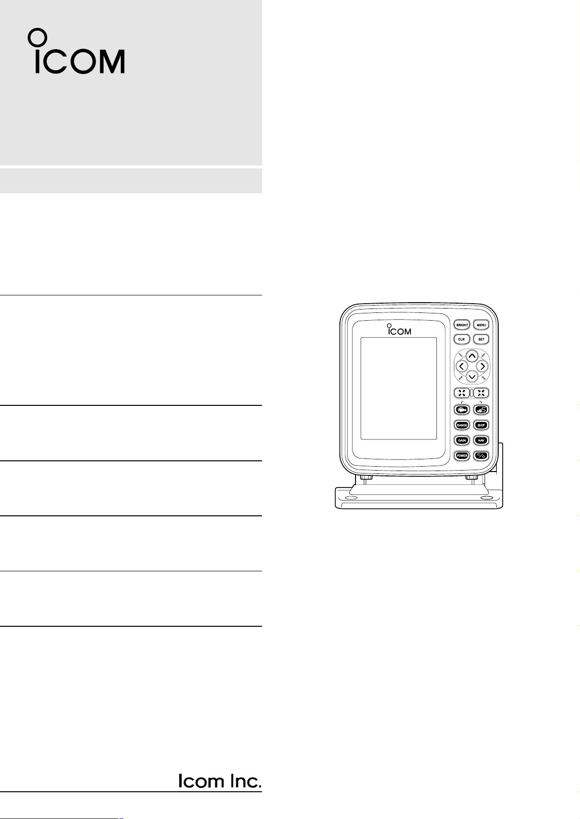
MARINEPLOTTER/SOUNDER
fp-561
COMBINE
Electronic charts are not legal
replacements for paper charts.
Always carry and consult current
official charts frequently.
FP-561
MARINE PLOTTER/SOUNDER
INSTRUCTION MANUAL
Page 2
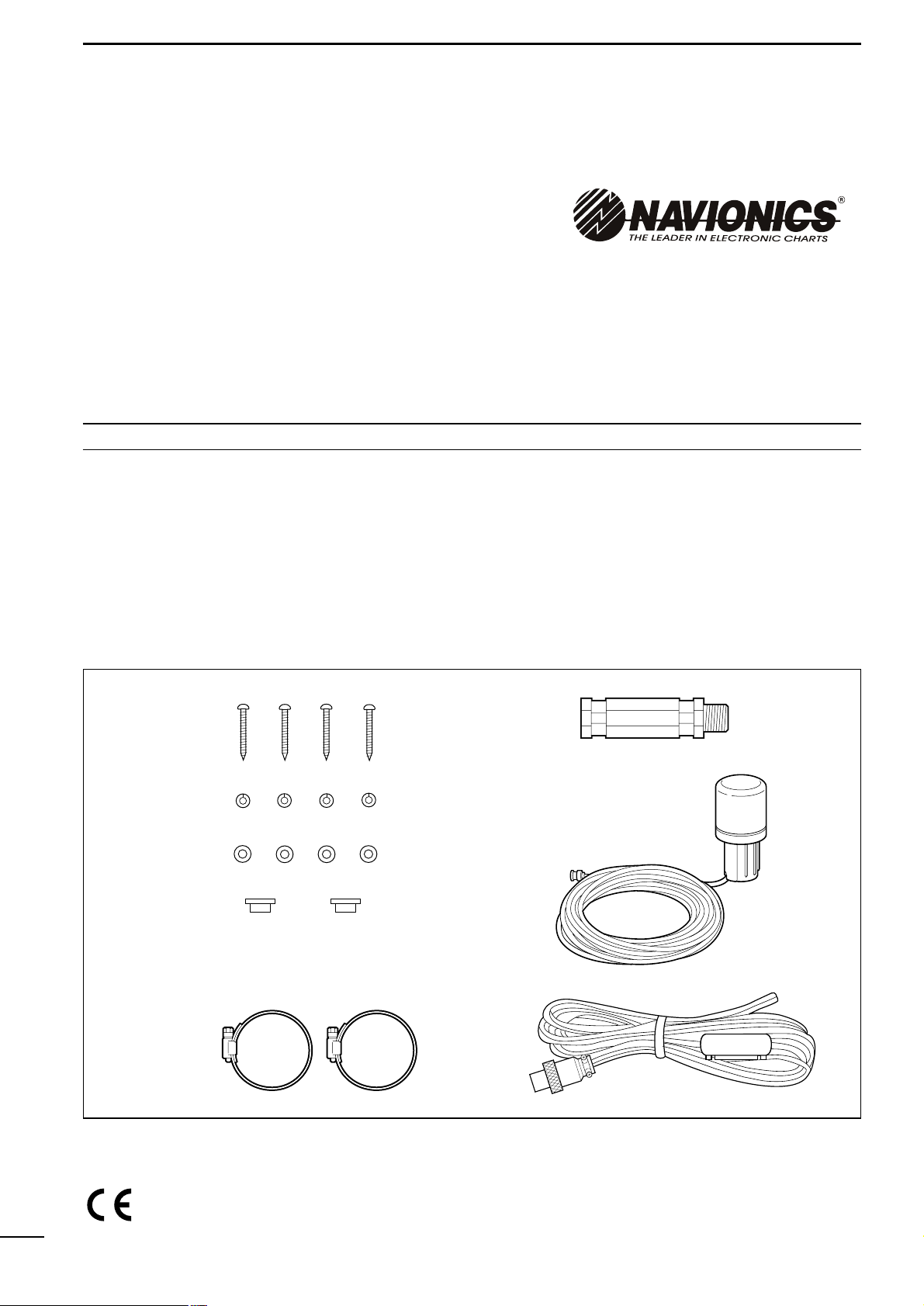
Qty.
qSelf-tapping screws (M 6 × 30)········································4
wSpring washers (M 6) ······················································4
eFlat washers (M 6)···························································4
rConnector covers·····························································2
tHorse band (HAS-40)······················································2
yExtention pipe (2273 PIPE)·············································1
uGPS antenna···································································1
iPower cable (OPC-786)···················································1
INTRODUCTION
Thank you very much for purchasing the FP-561.
The FP-561 is an advanced navigation and fishfinding system of compact design into which a marine
navigator with a built-in GPS receiver and a
fishfinder are integrated.
Connecting the PD-200, a DGPS beacon receiver,
to this system will permit the GPS to pinpoint the
ship location more accurately.
Please read this instruction manual carefully to ensure correct and efficient use of the product.
SUPPLIED ACCESSORIES
● Instruction manual
Cartgraphy supplied by
NAVIONICS Seamless chart start from
$99 and span the globe with high
detail and 16 zoom levels.
Ask your nearest NAVIONICS dealer
for more details.
i
Versions of the FP-561 which display “CE” on the serial
number seal, comply with the essential requirements of
the 89/336/EEC directive for Electromagnetic Compatibility.
w
q
e
r
y
i
u
t
Page 3

TABLE OF CONTENTS
INTRODUCTION . . . . . . . . . . . . . . . . . . . . . . . . . . . . . . . . . . . . . . . . . . . . . . . . . . . . . . . . . . . . . . . . . . . . . . . . . . . . . . . . .i
SUPPLIED ACCESSORIES . . . . . . . . . . . . . . . . . . . . . . . . . . . . . . . . . . . . . . . . . . . . . . . . . . . . . . . . . . . . . . . . . . . . . . . .i
TABLE OF CONTENTS . . . . . . . . . . . . . . . . . . . . . . . . . . . . . . . . . . . . . . . . . . . . . . . . . . . . . . . . . . . . . . . . . . . . . . . . . . .ii
1 SAFETY NOTICES . . . . . . . . . . . . . . . . . . . . . . . . . . . . . . . . . . . . . . . . . . . . . . . . . . . . . . . . . . . . . . . . . . . . . . . . . . . .1
2 PARTS AND FUNCTIONS . . . . . . . . . . . . . . . . . . . . . . . . . . . . . . . . . . . . . . . . . . . . . . . . . . . . . . . . . . . . . . . . . . . . . . . .
3 BASIC OPERATION . . . . . . . . . . . . . . . . . . . . . . . . . . . . . . . . . . . . . . . . . . . . . . . . . . . . . . . . . . . . . . . . . . . . . . . . . . . 5
3-1 Powering on or off the system . . . . . . . . . . . . . . . . . . . . . . . . . . . . . . . . . . . . . . . . . . . . . . . . . . . . . . . . . . . . . . . . 5
3-2 Adjusting the LCD brightness and contrast . . . . . . . . . . . . . . . . . . . . . . . . . . . . . . . . . . . . . . . . . . . . . . . . . . . . . . 5
3-3 Alarm sound . . . . . . . . . . . . . . . . . . . . . . . . . . . . . . . . . . . . . . . . . . . . . . . . . . . . . . . . . . . . . . . . . . . . . . . . . . . . . 5
4 AVAILABLE OPERATION MODES AND SCREENS . . . . . . . . . . . . . . . . . . . . . . . . . . . . . . . . . . . . . . . . . . . . . . . . . . . 6
4-1 How to change operation modes . . . . . . . . . . . . . . . . . . . . . . . . . . . . . . . . . . . . . . . . . . . . . . . . . . . . . . . . . . . . . . 6
4-2 Menu operation . . . . . . . . . . . . . . . . . . . . . . . . . . . . . . . . . . . . . . . . . . . . . . . . . . . . . . . . . . . . . . . . . . . . . . . . . . . 7
4-3 Electronic Chart card . . . . . . . . . . . . . . . . . . . . . . . . . . . . . . . . . . . . . . . . . . . . . . . . . . . . . . . . . . . . . . . . . . . . . . . 8
| How to insert a Electronic Chart card . . . . . . . . . . . . . . . . . . . . . . . . . . . . . . . . . . . . . . . . . . . . . . . . . . . . . . . . . . 8
Plotter Mode . . . . . . . . . . . . . . . . . . . . . . . . . . . . . . . . . . . . . . . . . . . . . . . . . . . . . . . . . . . . . . . . . . . . . . . . . . . . . . . . . . 10
Sounder Mode . . . . . . . . . . . . . . . . . . . . . . . . . . . . . . . . . . . . . . . . . . . . . . . . . . . . . . . . . . . . . . . . . . . . . . . . . . . . . . . . 42
Combination Mode . . . . . . . . . . . . . . . . . . . . . . . . . . . . . . . . . . . . . . . . . . . . . . . . . . . . . . . . . . . . . . . . . . . . . . . . . . . 61
5 INITIAL SETTING AFTER INSTALLATION . . . . . . . . . . . . . . . . . . . . . . . . . . . . . . . . . . . . . . . . . . . . . . . . . . . . . . . . . 62
5-1 Initial setting on the SET MODE screen . . . . . . . . . . . . . . . . . . . . . . . . . . . . . . . . . . . . . . . . . . . . . . . . . . . . . . . 62
5-2 Initial setting on each submenu screen . . . . . . . . . . . . . . . . . . . . . . . . . . . . . . . . . . . . . . . . . . . . . . . . . . . . . . . . 62
| Operation flow on the SET MODE screen . . . . . . . . . . . . . . . . . . . . . . . . . . . . . . . . . . . . . . . . . . . . . . . . . . . . . . 62
5-3 UNIT (Setting units of measure) . . . . . . . . . . . . . . . . . . . . . . . . . . . . . . . . . . . . . . . . . . . . . . . . . . . . . . . . . . . . . 63
| Setting the units of depth, water temperature, distance and ship speed . . . . . . . . . . . . . . . . . . . . . . . . . . . . . . . 63
5-4 SETTING (Correcting Plotter and Sounder parameters) . . . . . . . . . . . . . . . . . . . . . . . . . . . . . . . . . . . . . . . . . . . 63
(AUTO GAIN, FRAFT ADJUST, TEMPERATURE ADJUST, DATUM, BEARING, COMPASS INDICATION, TIME
REFERENCE, OFFSET TIME, SPEED DATA, SPEED ADJUST, NMEA OUT, BOD OUT)
5-5 RANGE SELECTION (Registering depth ranges) . . . . . . . . . . . . . . . . . . . . . . . . . . . . . . . . . . . . . . . . . . . . . . . . 67
5-6 ALL RESET (Restoring the original settings) . . . . . . . . . . . . . . . . . . . . . . . . . . . . . . . . . . . . . . . . . . . . . . . . . . . 67
6 INSTALLATION PROCEDURE . . . . . . . . . . . . . . . . . . . . . . . . . . . . . . . . . . . . . . . . . . . . . . . . . . . . . . . . . . . . . . . . . . 68
6-1 Overall connection diagram . . . . . . . . . . . . . . . . . . . . . . . . . . . . . . . . . . . . . . . . . . . . . . . . . . . . . . . . . . . . . . . . . 68
6-2 Installation procedure . . . . . . . . . . . . . . . . . . . . . . . . . . . . . . . . . . . . . . . . . . . . . . . . . . . . . . . . . . . . . . . . . . . . . 68
Å Installation place of the main unit . . . . . . . . . . . . . . . . . . . . . . . . . . . . . . . . . . . . . . . . . . . . . . . . . . . . . . . . . . . . 68
ı Installing the main unit . . . . . . . . . . . . . . . . . . . . . . . . . . . . . . . . . . . . . . . . . . . . . . . . . . . . . . . . . . . . . . . . . . . . . 69
Ç Connecting the power cable . . . . . . . . . . . . . . . . . . . . . . . . . . . . . . . . . . . . . . . . . . . . . . . . . . . . . . . . . . . . . . . . 70
Î Connecting a ground cable . . . . . . . . . . . . . . . . . . . . . . . . . . . . . . . . . . . . . . . . . . . . . . . . . . . . . . . . . . . . . . . . . 70
6-3 Measures against noises from the generator . . . . . . . . . . . . . . . . . . . . . . . . . . . . . . . . . . . . . . . . . . . . . . . . . . . 70
6-4 Mounting the GPS antenna . . . . . . . . . . . . . . . . . . . . . . . . . . . . . . . . . . . . . . . . . . . . . . . . . . . . . . . . . . . . . . . . . 71
6-5 Installing an optional transducer . . . . . . . . . . . . . . . . . . . . . . . . . . . . . . . . . . . . . . . . . . . . . . . . . . . . . . . . . . . . . 72
Å Optional transducers and accessories . . . . . . . . . . . . . . . . . . . . . . . . . . . . . . . . . . . . . . . . . . . . . . . . . . . . . . . . 72
ı Installation position . . . . . . . . . . . . . . . . . . . . . . . . . . . . . . . . . . . . . . . . . . . . . . . . . . . . . . . . . . . . . . . . . . . . . . . 72
6-6 Connecting an external navigator . . . . . . . . . . . . . . . . . . . . . . . . . . . . . . . . . . . . . . . . . . . . . . . . . . . . . . . . . . . . 73
6-7 DGPS . . . . . . . . . . . . . . . . . . . . . . . . . . . . . . . . . . . . . . . . . . . . . . . . . . . . . . . . . . . . . . . . . . . . . . . . . . . . . . . . . 73
7 MAINTENANCE . . . . . . . . . . . . . . . . . . . . . . . . . . . . . . . . . . . . . . . . . . . . . . . . . . . . . . . . . . . . . . . . . . . . . . . . . . . . . 74
7-1 Maintenance and inspection . . . . . . . . . . . . . . . . . . . . . . . . . . . . . . . . . . . . . . . . . . . . . . . . . . . . . . . . . . . . . . . . 74
7-2 Replacing the fuse . . . . . . . . . . . . . . . . . . . . . . . . . . . . . . . . . . . . . . . . . . . . . . . . . . . . . . . . . . . . . . . . . . . . . . . . 74
8 SPECIFICATIONS . . . . . . . . . . . . . . . . . . . . . . . . . . . . . . . . . . . . . . . . . . . . . . . . . . . . . . . . . . . . . . . . . . . . . . . . . . . . 75
9 DATUM (GEODETIC REFERENCE) CODE . . . . . . . . . . . . . . . . . . . . . . . . . . . . . . . . . . . . . . . . . . . . . . . . . . . . . . . . . 78
ii
Page 4
1
1
SAFETY NOTICES
Be sure to read the following safety notices to ensure safe use of the product.
¡ The safety notices are for preventing personal injury
and property damage.
¡ Observe the following safety notices to ensure safe
and proper used of the product.
¡ After you finish reading this manual, store it in a safe
place for future reference.
Each of the following warning notices indicates that neglecting the suggested procedure
or practice may result in death or serious personal injury.
¡ Be sure turn off the power by pressing the power ke y
or disconnect the power cable from the battery
immediately when the product produces smoke or
smells of something burning.
Failure to do so may cause a fire or electric shock.
After making sure that smoking ceases, contact your
dealer or our service personnel for inspection.
¡ Do not install the product in areas where it is
exposed to flammable gases.
Doing so may cause a fire or an explosion.
¡ Supply the product with the specified voltage or use
the specified power supply.
Otherwise, a malfunction or fire may result.
¡ Use the specified fuse.
Otherwise, a malfunction or fire may result.
¡ Do not remove the cover and touch internal parts of
the product.
Doing so may cause death due to a high voltage inside
the product.
Servicing and adjustment of the product must be performed by competent persons.
¡ Be sure to electrically ground the pr oduct to the hull.
Failure to do so may cause electric shock or leak.
¡ Be careful to prevent foreign objects from entering
the product.
Foreign objects including metal chips, wire scraps and
liquids inside the product may cause a shortcircuit, fire or
malfunction.
¡ A through-the-hull type echo sounding transducer
must be installed by a shipbuilder or an expert
installer.
Otherwise, the ship could be waterlogged.
R
WARNING
Each of the following caution notices indicates that neglecting the suggested procedure
or practice may result in personal injury or property damage.
¡ Navigation-aid data among other information pr ovid-
ed by the product is not intended for navigational
use by itself.
For detailed and latest information for na vigation, consult
nautical charts and Notices to Mariners.
¡ Always hold the plug when removing the power
cable from the power supply.
Pulling the power cable may cause damage to the po w er
cable and a fire or electric shock.
¡ Do not install the product, antenna and transducer in
areas other than specified.
Doing so may cause an accident or a malfunction.
¡ Do not expose the product to water.
Doing so may cause a malfunction or fire.
¡ Never modify or attempt to repair the product by
yourself.
Doing so could cause a malfunction or fire.
Only competent persons are allowed to modify or repair
the product.
¡ Do not scrape, tailor, strain, twist, or put a heavy
object on, the power cable.
Doing so may damage the cable, resulting in a fire or
electric shock.
¡ Do not touch the power cable with wet hands.
Doing so may cause electric shock.
¡ Observe the polarity when plugging the product to
the power supply.
Reverse connection will cause a malfunction or fire.
R
CAUTION
Page 5
2
1
SAFETY NOTICES
Each of the following caution notices indicates that neglecting the suggested procedure
or practice may result in personal injury or property damage.
Data card handling precautions:
¡ Do not put data cards into such a pocket or poly bag that
is electrically charged.
¡ Do not leave data cards in an area e xposed to direct sun-
light or seawater.
¡ Be careful to prevent dust or dirt from entering the con-
nector of data cards (keep the card slot free of dirt).
¡ Do not bend data cards or put a heavy object on them.
¡ Do not throw or drop data cards.
¡ Be sure to power off the product before inserting or
removing a data card to or from the card slot.
R
CAUTION
Other precautions
¡ Do not install the product close to speakers, pow er trans-
formers or other equipment that produces a magnetic
field.
¡ When starting the engine of the ship involves a rapid fall
in supply voltage to the product, be sure to start the
engine before powering on the product.
¡ Avoid using organic solvents such as thinner or benzene
to clean the product.
These solvents will cause damage to the product surface.
To clan the product or antenna, wipe it using a soft cloth
damped with a water-diluted detergent.
¡ The product contains a lithium battery (having a life of
approx. five years) which retains GPS positioning data.
If this backup battery is completely dead, the GPS
almanac data is lost and it will take a long time to acquire
navigational satellites. Registered navigational marks
and routes are also lost.
If these symptoms appear, contact your dealer or our
local sales office.
¡ The LCD is of high-density type having an effective pixel
percentage of at least 99.99%; it may have an ineffective
pixel or “always active” pixel percentage of max. 0.01%
under normal conditions.
¡ The LCD is a consumable component and has a life
expectancy of approx. 10,000 operation hours. When
the service life expires, the LCD screen will darken, flick-
er or provide no display.
At the first sign of these symptoms, the LCD should be
replaced. Consult your dealer or our service personnel.
Page 6
2
PARTS AND FUNCTIONS
3
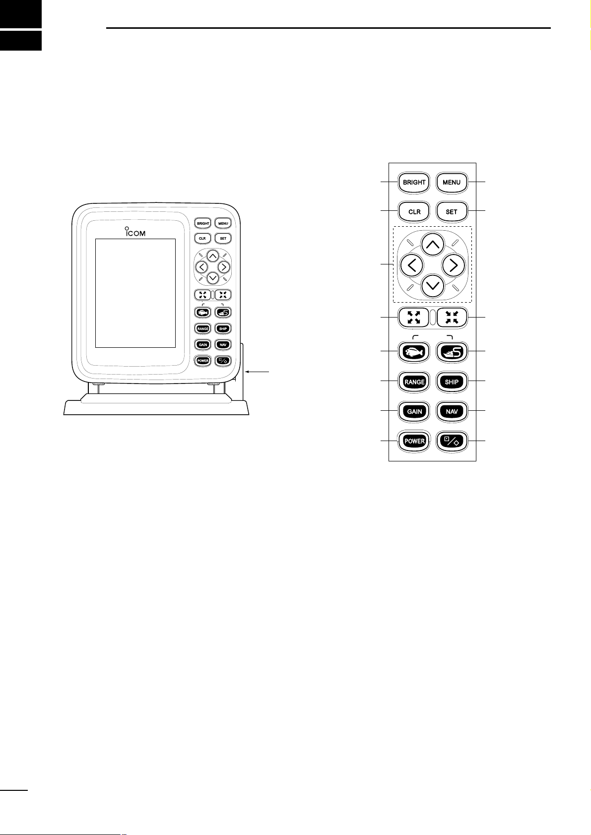
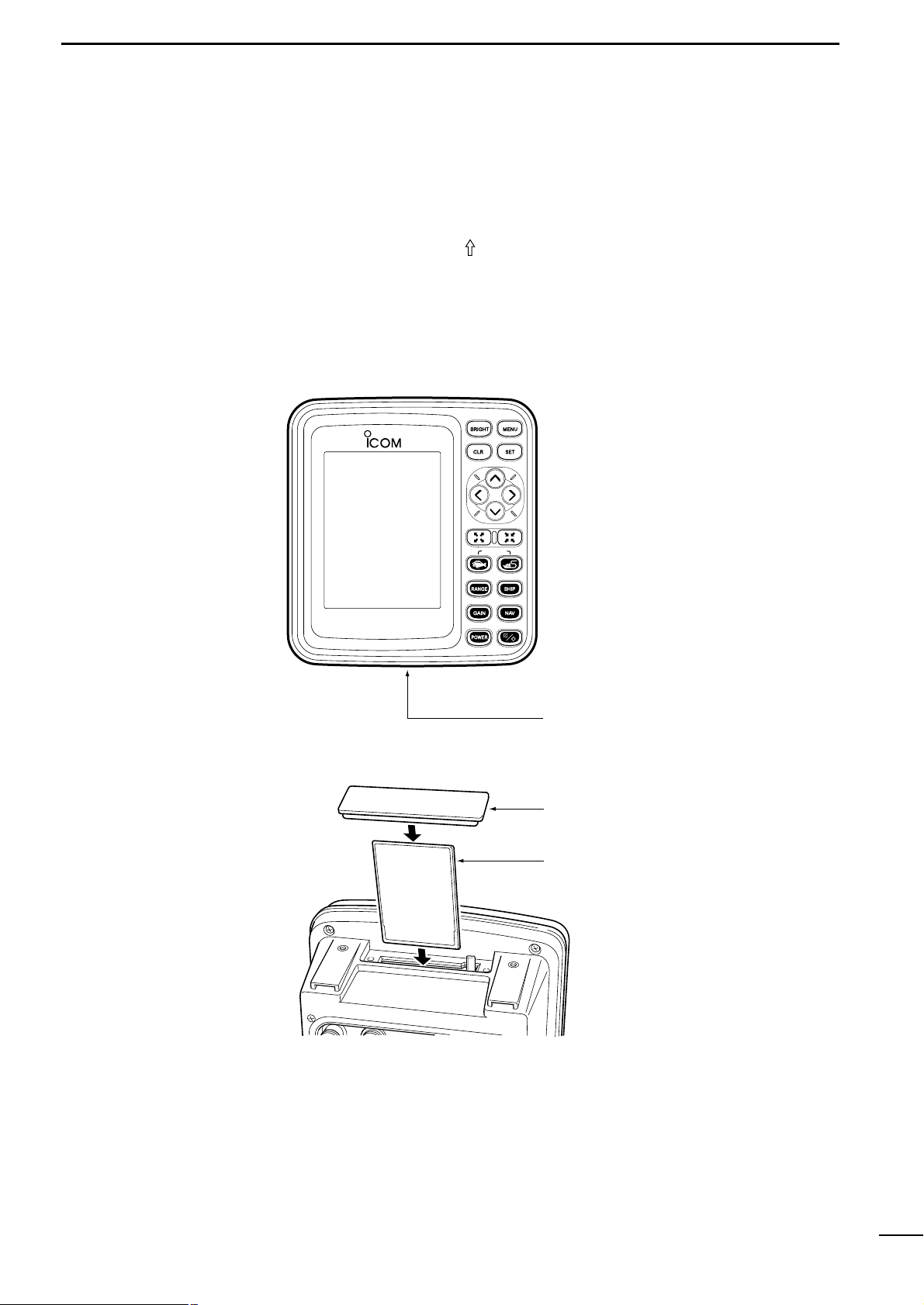
|Main unit
MARINEPLOTTER/SOUNDER
FP-561
COMBINE
!5
!0
!4
!3
!2
oi
t
r
e
w
q
u
y
!1
Tilting lever
COMBINE
|Operation panel
Page 7
4
2
PARTS AND FUNCTIONS
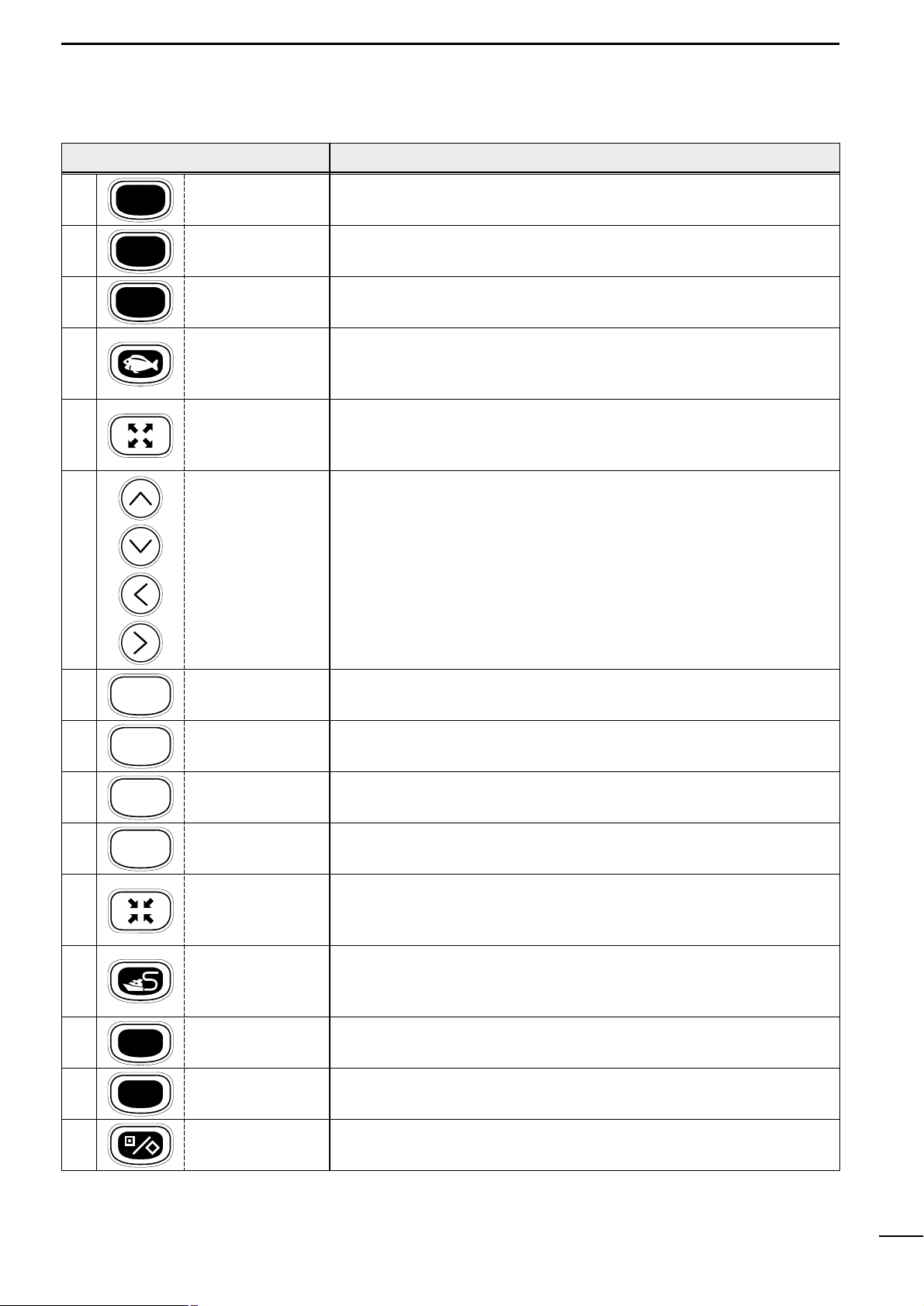
FUNCTION
Press to power on or off the product (☞ P. 5).
Each time this key is pressed, the power is turned on and off alternately.
Use to set the image sensitivity (☞ P. 52) on the fishfinder screen.
Use to set the depth range (☞ P. 52) or depth shift (☞ P. 53), or to enter auto
operation (☞ P. 53).
Use to select the fishfinder mode (☞ Pgs. 6 & 44).
Using the [SOUNDER]-[PLOTTER] key combination causes the system to
enter the Combination mode.
Use to zoom in the coastline screen image (☞ P. 18).
This key can be used to zoom in the bottom rock screen image and the marker
zoom-in screen image.
Use to activate and move the cross hair cursor (☞ P. 18) and fishfinder
markers.
These keys can also be used to select a menu item or change settings.
* To move the cross hair cursor:
Using the [UP]-[LEFT] or [UP]-[RIGHT] key combination allows you to move
the cross hair cursor to the upper left of right.
Using the [DOWN]-[LEFT] or [DOWN]-[RIGHT] key combination allows you to
move the cross hair cursor to the lower left or right.
Use to delete marks or abort setting on various screens.
Use to adjust the brightness and contract (☞ P. 5) of screen display.
Use to select the menu screen (☞ P. 7).
Use to execute operations or save settings.
Use to zoom out the coastline screen image (☞ P. 18).
This key can also be used to zoom out the bottom rock screen image and the
marker zoom-in screen image.
Use to select the plotter mode (☞ Pgs. 6 & 12).
Using the [PLOTTER]-[SOUNDER] key combination causes the system to
enter the Combination mode.
Use to center the current ship position on a screen (☞ P. 19).
Pressing this key causes the cross hair cursor to disappear from the screen.
Use to select either of the destination navigation or the route navigation
(☞ Pgs. 28 & 29).
Use to edit or register marks (☞ P. 26).
POWER
GAIN
RANGE
CLR
BRIGHT
MENU
SET
SHIP
NAV
[POWER] key
[GAIN] key
[RANGE] key
[SOUNDER] key
[ZOOM-IN] key
[CLR] key
[BRIGHT] key
[MENU] key
[SET] key
[ZOOM-OUT] key
[PLOTTER] key
[SHIP] key
[NAV] key
[MARK] key
q
w
e
r
t
y
u
i
o
!0
!1
!2
!3
!4
!5
[UP] key
[DOWN] key
[LEFT] key
[RIGHT] key
KEY
Page 8
5
3-1 P owering on or off the
system
After installing the system, be sure to perform initial setting according to the
instructions in Chapter 5 “Initial Setting after Installation” (☞ P. 62 ff.).
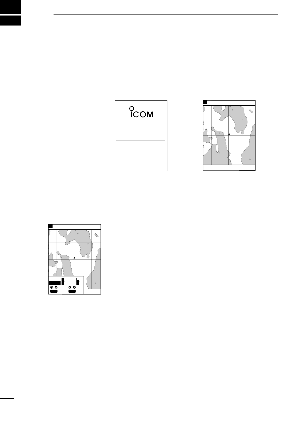
q Press the [POWER] key.
The system will sound an electronic beep, display the opening screen for
approx. ten seconds and then enter the screen where you left off.
w To power off the system, press the [POWER] key again.
3
BASIC OPERATION
MARINEPLOTTER
/SOUNDER
fp- 561
WARNING:
This electronic chart is an aid to
navigation designed to facilitate the use
of authorized government charts, not to
replace them. Only official government
charts and notices to mariners contain all
of the current information needed for the
safety of navigation, and the captain is
responsible for their prudent use.
Opening screen
8
GPS 48°21.417N 125°26.643W
57.6 FT315°T 10.2KT 58°F
RANGE 32
After approx. 10 seconds
8
GPS 48°21.417N 125°26.643W
57.6 FT
CONT
BRIGHT
CLR
SET
SET
CANC
ADJ
SEL
ADJADJ
The LCD can be adjusted in brightness and contrast according to the environment of the installation site.
q Press the [BRIGHT] key.
A level bar indicating the LCD brightness and contrast will appear at the lower
left of the screen.
w Press the [LEFT] or [RIGHT] key to select setting item “Brightness” or
“Contrast”.
The selected item is highlighted in blue.
e Press [UP] or [DOWN] key to set the selected item.
r Press the [SET] key to save the setting.
3-2 Adjusting the LCD
brightness and contrast
3-3 Alarm sound
The system produces an alarm sound when key operation is erroneous or
invalid.
You will hear an alarm sound when
¡ pressing an inoperative key,
¡ performing erroneous key operation,
¡ pressing an invalid key in plotter mode,
¡ pressing an invalid key in sounder mode,
¡ pressing an invalid key in combination mode, or
¡ pressing an invalid key on a menu screen.
Note that an electronic beep sound is heard when the power is turned on or correct key operation is done.
Page 9
6
4
AVAILABLE OPERATION MODES AND SCREENS
4-1 How to change operation
modes
Three operation modes are available for this system: the plotter mode,
sounder mode and combination mode.
To change the operation mode, proceed as follows.
q
When the system is in plotter mode:
Press the [SOUNDER] key. The system will enter the fishfinder mode.
w
When the system is in fishfinder mode:
Press the [PLOTTER] key. The system will enter the plotter mode.
e
When the system in plotter or fishfinder mode:
Press the [SOUNDER] and [PLOTTER] keys simultaneously. The system will
enter the combination mode.
r
When the system is in combination mode:
Press the [SOUNDER] or [PLOTTER] key. The system will enter the mode corresponding to the key pressed.
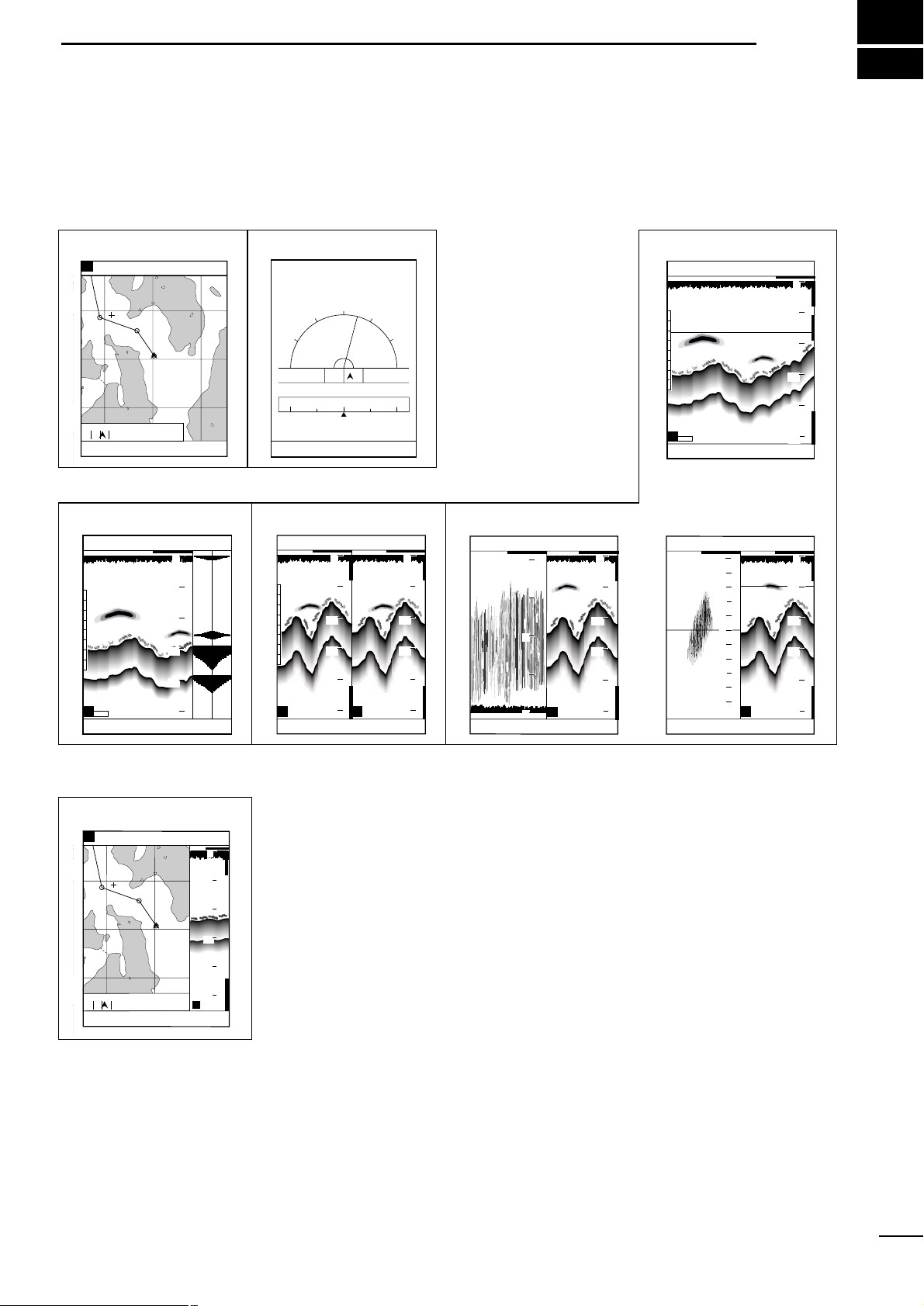
In combination mode, only the combination screen is available. This screen consists of the following two screens.
Standard screen of fishfinder mode
Coastline screen of plotter mode
When the combination mode is canceled, the display will move to the standard
screen of the fishfinder mode or the coastline screen of the plotter mode.
¡Plotter mode
¡Combination
¡Sounder mode
Coastline screen Navigation monitor screen
LON
LAT
60゜
90゜
30゜
15゜R
30゜
0゜
60゜
90゜
DEVIATION
0.03 NM
124゜23.165W
48゜50.705N
N
E
W
NW NE
Standard screen
Standard + A scope screen
Combination mode
Dual screen Standard + Bottom lock screen
Standard +
Marker zoom-in screen
FT
43.4
315
°T 10.
2KT 58°F
W P 1 TIME 12:34
D/D 10.45NM TTG 1:17
C/D 325°T ETA 13:51
D/FD 15.22NM TTFD 2:34
GPS 48°21.417N 125°26.643W
31.5
H
AUTO
FT
43.4
315
°T 10.
2KT 58°F
20
40
60
80
0
100
H
2
1
3
4
5
0
3
4
2
1
5
GPS 48°21.417N 125°26.643W
19.5
FT
43.4
315
°T 10.
2KT 58°F
20
40
60
80
0
100
0
10
5
H
FT
57.6
315
°T 10.
2KT 58°F
GPS 48°21.417N 125°26.643W
20
40
60
80
0
100
L
H
FT
43.4
315
°T 10.
2KT 58°F
GPS 48°21.417N 125°26.643W
20
40
60
80
0
100
20
40
60
80
0
100
AUTO
H
FT
57.6
315
°T 10.
2KT 58°F
GPS 48°21.417N 125°26.643W
20
40
60
80
0
100
8
GPS 48°21.417N 125°26.643W
RANGE 32
FT
57.6
0°
T 10.
2KT 58°F
1
0
2
TO WP 1
4.6NM 320°
8
GPS 48°21.417N 125°26.643W
RANGE 32
FT
43.4
0°
T 10.
2KT 58°F
1
0
2
TO WP 1
4.6NM 320°
H
0
20
40
60
80
100
Page 10
7
4
AVAILABLE OPERATION MODES AND SCREENS
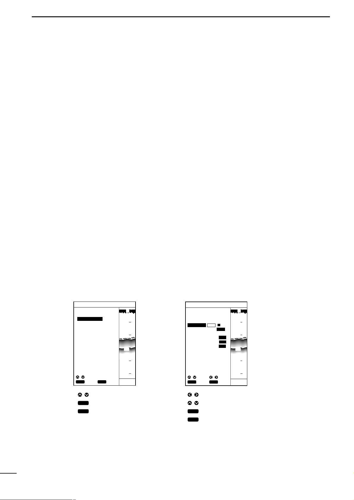
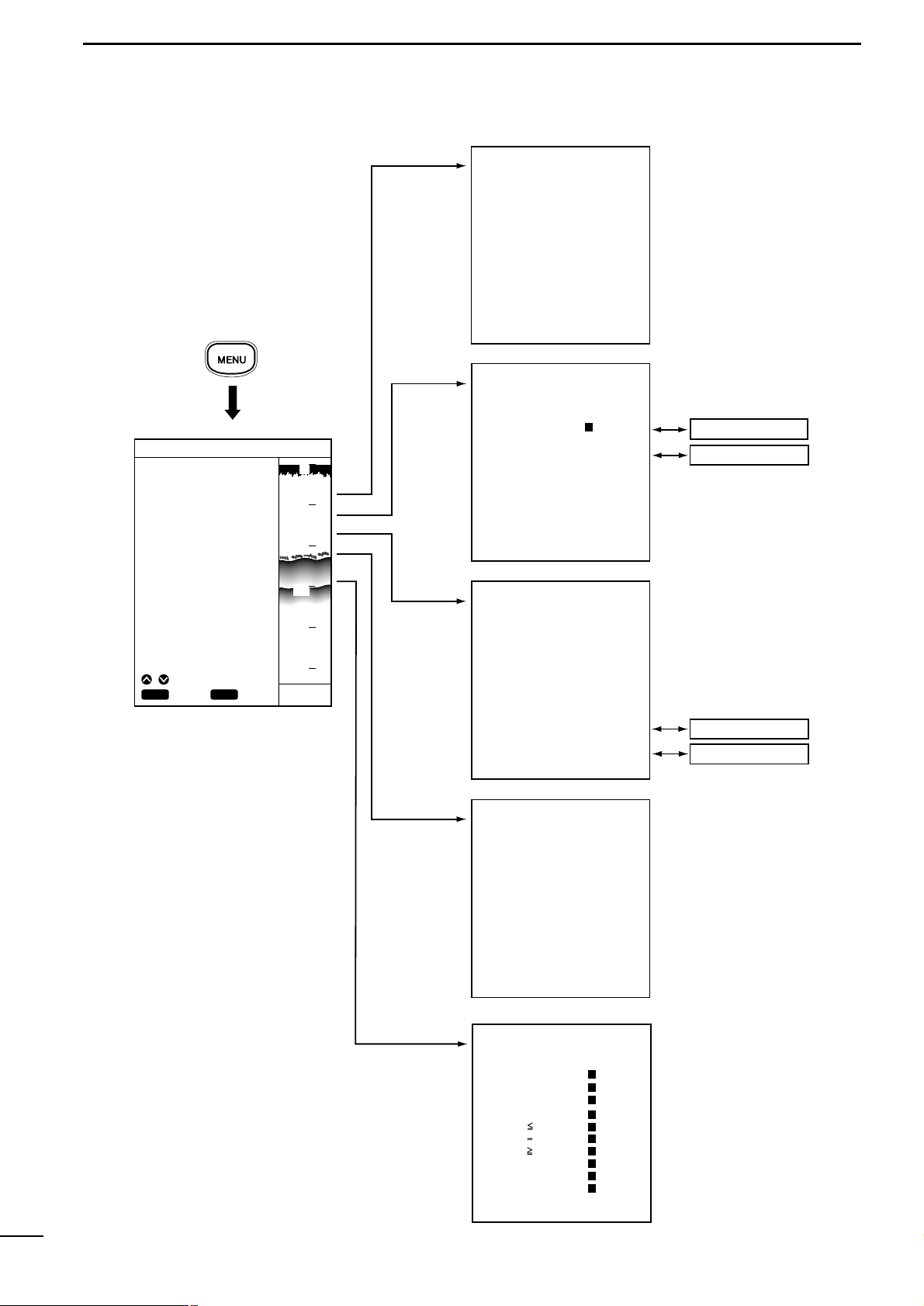
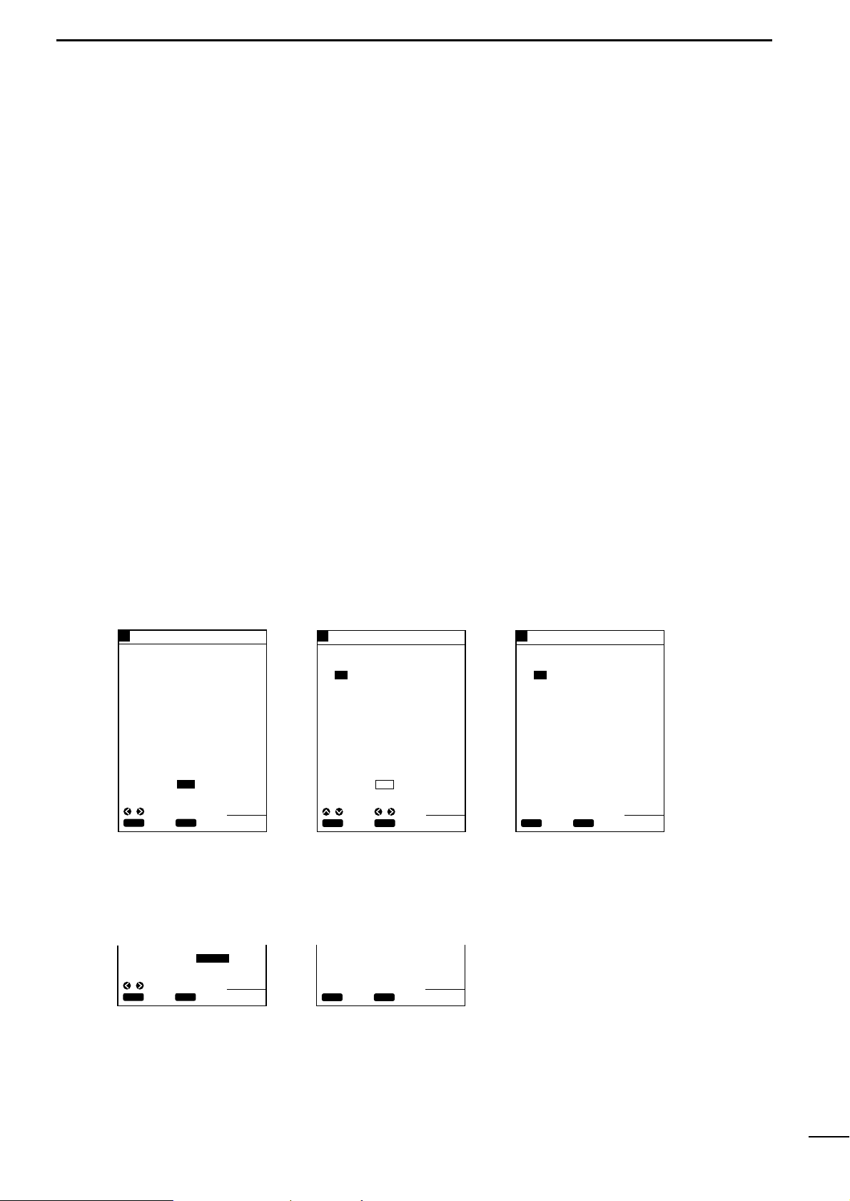
4-2 Menu operation
Menu screens allows you to select and execute various functions of the system or to change various settings.
For available menu screens and the menu structure, see page 9.
The following summarizes the menu operation flow.
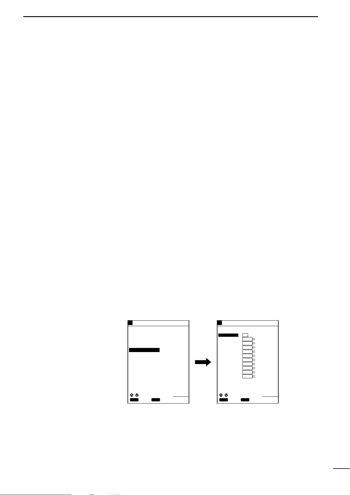
q Press the [MENU] key.
The Main Menu screen will appear.
The currently selected menu item (a submenu) is highlighted in yellow.
w Select the desired submenu (e.g., Plotter Menu) using the [UP] or [DOWN] key
and press the [SET] key.
The selected submenu (e.g., Plotter Menu) screen will appear.
On the submenu screen, the currently selected menu item (setting item) is highlighted in yellow.
e Select the desired setting item using the [UP] or [DOWN] key and press the
[SET] key.
The selected setting item turns blue and the corresponding setting field is highlighted in yellow.
* While any setting item is highlighted in blue, you cannot move to other submenu
screens.
r Select the desired setting option in the setting field using the [LEFT] or [RIGHT]
key and press the [SET] key.
Alternatively, select the desired digit using the [LEFT] or [RIGHT] key and enter
or change the value using the [UP] or [DOWN] key; then press the [SET] key.
t Repeat step r above for each setting item.
y Repeat steps e to t above for each submenu.
u When you finish setting, press the [CLR] momentarily to close the Main Menu
screen.
For detailed description of setting on each submenu screen, see the appropriate
section.
MAIN MENU
POSITIONING MENU
PLOTTER MENU
ALARM MENU
SOUNDER MENU
PLOTTER MENU
TRK ERASE
ROUTE ENTER/EDIT→
MARK ENTER/ERASE→
GPS 48°21.417N 125°26.643W
¡Main Menu screen ¡Plotter Menu screen
Press to select a submenu.
Press to open the submenu.
Press to return to the previous
screen.
Use to select a setting option or digit.
Use to change the value of the digit.
Press to confirm and save the setting.
Press to clear or cancel the setting and return to
the item selection step.
When pressing this key during the item selection
step, you will returns to the previous screen.
SCREEN SETTING
TRK COLOR WHIT OFF
HEADING ON OFF
FRONT WIDE ON OFF
OVER ZOOM ON OFF
TRK STEP 30S 1.00NM
GPS 48°21.417N 125°26.643W
CLR
ENT
SET
CANC
SEL
CLR
ENT
SET
CANC
SEL
CLR
SET
SET
CANC
ADJ
SEL
43.4 FT
43.4 FT
CLR
SET
SET
CANC
ADJ
SEL
20
40
60
80
0
100
20
40
60
80
0
100
Page 11
Card cover
ERC card
(Insert an ERC card with its face directed
to the same direction as the display)
Card slot located at the bottom
FP-560
MARINEPLOTTER/SOUNDER
fp-561
Card slot
COMBINE
8
4
AVAILABLE OPERATION MODES AND SCREENS
4-3 Electronic Chartcard
| How to insert a Electronic Chart
card
Be sure to power off the system before inserting or removing a Electronic
Chart card into or from the card slot.
Insert a NAVIONICS® Electronic Chart card carefully into the card slot with the
card face (on which “” is mar ked) directed to the same direction as the display.
Forcing a Electronic Chart card into the slot will cause damage to the card socket
in the slot.
If the system fails to operate normally even through an Electronic Chart card has
been inserted, remove the card once and then reinsert it.
NAVIONICS® Electronic Char t
(Microcharts
TM
)
FP-561
Page 12
9
4
AVAILABLE OPERATION MODES AND SCREENS
ROUTE ENTER/EDIT
MARK ENTER/ERASE
DGPS
POSITIONING INFO
CLR
ENT
SET
CANC
SEL
Press the
[MENU] key.
SOUNDER MENU
DSP SPEED 5 STOP
STC 1
I.R ON OFF
N.R 1 OFF
FREQUENCY L H
PLOTTER MENU
TRK ERASE
HEADING ON OFF
ROUTE ENTER/EDIT→
MARK ENTER/ERASE→
TRK COLOR WHIT OFF
TRK STEP 30S 1.00 NM
FRONT WIDE ON OFF
OVER ZOOM ON OFF
POSITIONING MENU
POS CORR GOTOCURSUR
AVERAGING 1 OFF
POSITIONING INFO→
DGPS→
LON E0.000
LAT N0.000
ALARM MENU
DEPTH 1m OFF
SHALLOW 1m OFF
FISH DEPTH 1m OFF
ALARM ZONE 0.01NM OFF
MAIN MENU
POSITIONING MENU
PLOTTER MENU
ALARM MENU
SOUNDER MENU
GPS 48°21.417N 125°26.643W
POS EQUIP GPS NMEA
SCREEN MENU
WIDTH 1m
SCREEN SETTING
LAND YELL CSLN
BKG COLOR BLUE
SEA BLUE
NAME WHIT OFF
D CON 5m LBLU OFF
D CON 10m LBLU OFF
D CON 20m LBLU OFF
LIGHT RED OFF
GRID BLUE OFF
DISP MAPS WHIT OFF
DISP MODE 1 2
FT
43.4
20
40
60
80
0
100
•Menu operation flow
Page 13

10
4
r PLOTTER MODEq TABLE OF CONTENTS
!!!!!!!!!!!!!!!!!!!!!!!!!!!!!!!!!!!!!!!!!!!!!!!!!!
PLOTTER MODE
!!!!!!!!!!!!!!!!!!!!!!!!!!!!!!!!!!!!!!!!!!!!!!!!!!
(1) AVAILABLE SCREENS AND INDICATIONS.................................................................................................................... 12
(1)-1 How to access screens·········································································································································· 12
(1)-2 Coastline screen···················································································································································· 13
(1)-3 Navigation monitor screen····································································································································· 15
(1)-4 Positioning Information screen······························································································································· 16
(2) COASTLINE DATA MANIPULATION................................................................................................................................ 17
(2)-1 Zooming in or out coastline images······················································································································· 17
Å 16 reduced scales·················································································································································· 17
ı Ship-centering mode ············································································································································· 17
Ç Cursor-centering mode·········································································································································· 17
(2)-2 Ship-centering mode ············································································································································· 18
| Manual operation····································································································································· 18
(2)-3 Displaying the latitude and longitude lines············································································································· 18
(2)-4 Measuring the distance and azimuth between two points····················································································· 19
Å Measurement between the ship mark and the cursor position·············································································· 19
ı Measurement between two points specified with the cursor················································································· 19
(3) ROUTE REGISTRATION AND EDIT ................................................................................................................................ 20
(3)-1 Registering and editing navigation routes·············································································································· 20
Å Registering navigation routes································································································································ 20
ı Editing navigation routes······································································································································· 21
| Extending a navigation route ··················································································································· 21
| Clearing turning points····························································································································· 21
(3)-2 Clearing a route····················································································································································· 22
(3)-3 Character list·························································································································································· 23
(4) MARK MANIPULATION.................................................................................................................................................... 24
(4)-1 Registering marks·················································································································································· 24
Å Registration of marks from the Plotter Menu screen····························································································· 24
ı Registration of the current ship position mark on the coastline screen································································· 25
Ç Registration of marks located at any position on the coastline screen·································································· 25
(4)-2 Clearing marks ······················································································································································ 26
Å Clearing marks on the coastline screen ················································································································ 26
ı Clearing marks from the Plotter Menu screen······································································································· 26
(5) ROUTE NAVIGATION SETTING....................................................................................................................................... 27
(5)-1 Setting route navigation········································································································································· 27
| Changing the monitor range···················································································································· 27
(5)-2 Canceling route navigation···································································································································· 27
Page 14

11
4
r PLOTTER MODEq TABLE OF CONTENTS
(6) DESTINATION NAVIGATION SETTING ........................................................................................................................... 28
(6)-1 Setting destination navigation································································································································ 28
Å Setting destination navigation using existing registered marks············································································· 28
ı Setting destination navigation using a newly registered mark··············································································· 28
(6)-2 Canceling destination navigation··························································································································· 28
(7) TRACK MANIPULATION .................................................................................................................................................. 29
(7)-1 Setting the track color············································································································································ 29
(7)-2 Changing the tracking interval······························································································································· 29
(7)-3 Clearing the track··················································································································································· 30
(7)-4 Setting the heading vector······································································································································30
(7)-5 Setting the front wide function ································································································································30
(7)-6 Setting the over zoom function·······························································································································30
(8) DATA COLOR SETTING................................................................................................................................................... 31
(8)-1 Setting colors of data on screen···························································································································· 31
Å Specifying the color of land···································································································································· 31
ı Specifying the color of sea····································································································································· 31
Ç Specifying the color of place-names······················································································································ 32
Î Specifying the color of depth contours··················································································································· 32
´ Specifying the color of lights·································································································································· 32
Ï Specifying the color of map border························································································································ 33
˝ Specifying the display mode·································································································································· 33
(9) SELECTION OF POSITIONING DEVICE ......................................................................................................................... 34
(10) CORRECTION OF SHIP POSITIONING ERROR............................................................................................................. 35
(10)-1 Correcting a ship positioning error························································································································· 35
(10)-2 Correction using the cross hair cursor··················································································································· 35
(10)-3 Correction with latitude/longitude entry ················································································································· 35
(11) AVERAGING...................................................................................................................................................................... 36
(12) DGPS................................................................................................................................................................................. 37
(12)-1 DGPS····································································································································································· 37
(12)-2 Using the DGPS ···················································································································································· 37
(12)-3 Setting the beacon station····································································································································· 37
(12)-4 Setting the baud rate of the beacon station··········································································································· 38
(13) ACCESS TO POSITIONING INFORMATION SCREEN ................................................................................................... 38
(14) DOP AS A POSITIONING PRECISION INDICATOR....................................................................................................... 38
(15) ALARM FUNCTION .......................................................................................................................................................... 39
(15)-1 Available alarms····················································································································································· 39
(15)-2 Setting the alarm zone··········································································································································· 40
Page 15
12
1
r PLOTTER MODEq AVAILABLE SCREENS AND INDICATIONS
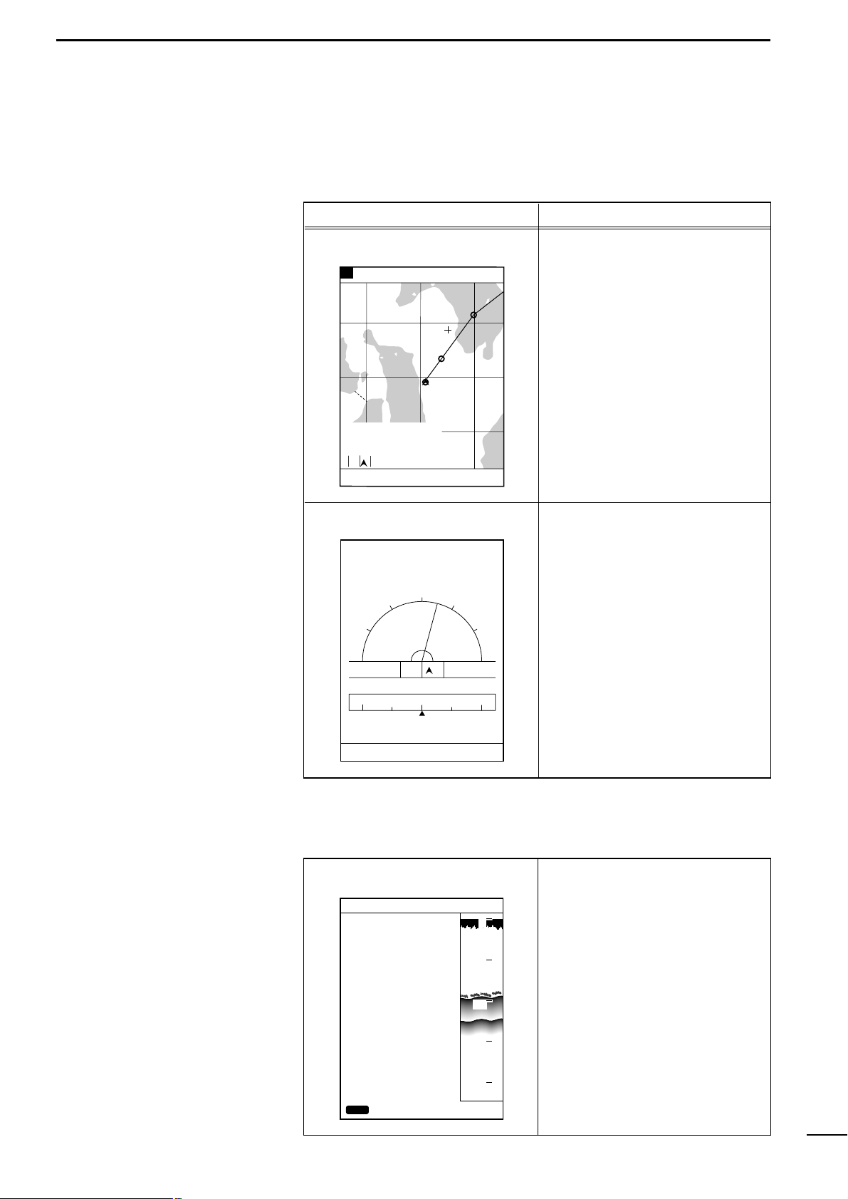
(1)-1 How to access screens
In plotter mode, the following two screens are available.
Pressing the [PLOTTER] key in plotter mode allows selection between the coastline screen and the navigation monitor screen.
This screen indicates various navigational data including coastlines, track
and marks.
This screen indicates easy-to-understand graphical and text information
helpful for navigation.
This screen shows GPS/DGPS information.
Screen No. and name Description
Coastline screen
Navigation monitor screen
Positioning Information screen
80.0 FT0°T 12KT 54.3°F
RANGE 32
2
0
1
8
DGPS34゚18.000N135゚01.000E
TO WP 1
23.00NM 30°
34°21.362N 28°
135°06.950E 18.05
NM
1:32
80.0 FT0°T 12KT 54.3°F
LON
LAT
60゜
90゜
30゜
345°
15゜R
30゜
0゜
60゜
90゜
14:25
01:05
15:30
TIME
TTG
ETA
15:30TTFD
W P
No. 1
D/D
C/D
D/FD
10.45NM
10.45NM
DEVIATION
0.03
NM
134°01.000E
34°18.000N
N
E
W
NW NE
0
10
20
30
40
POSITIONING INFO
SAT# S/N BRG ELV
DOP
DGPS INFOMATION
RD-200
Rev.1.1
FREQUENCY 283.5
kHz
BAUD RATE 200
S/N 00
1.50
BACK
12 50 0 81
15 45 90 79
02 40 180 56
16 52 270 63
20 60 45 30
22 30 135 10
10 56 225 25
09 63 315 44
DGPS34゚18.000N135゚01.000E
CLR
80.0FT
The Positioning Information screen can be accessed from the Positioning
Menu screen. (☞ P. 38)
Page 16
13
1
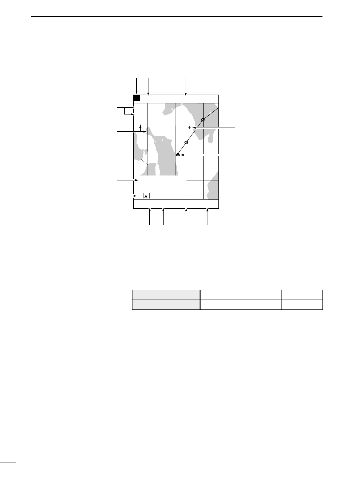
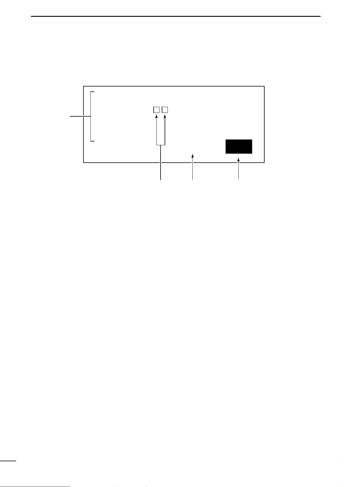
r PLOTTER MODEq AVAILABLE SCREENS AND INDICATIONS
This field shows the current scale to which the coast line image is displayed. The
coastline image can be zoomed in or out to a total of 16 scales (☞ P. 17).
This field shows the positioning device in use.
This field shows the current ship position in latitude/longitude.
White characters in the field mean that the positioning is done normally.
Red characters in the field suggest that the system fails to pinpoint the current ship
position due to a positioning error or the like.
The field is blank if no data is received for 10 seconds or more due to a connection
error.
The cross hair cursor appears on the screen when the [UP]/[DOWN] or
[LEFT]/[RIGHT] key is pressed.
This mark shows the current ship position. The ship is currently located at the center of this mark.
This mark changes to “\” when the ship slows down to 3 knots (or equivalent in
km/h or Ml/h) or less.
This field shows the current depth of water.
(1)-2 Coastline screen
2
0
1
8
DGPS34゚18.000N135゚01.000E
0°T 12KT 54.3°F
ARRV
ALRM
FISH
ALRM
RANGE 32
TO WP 1
23.00NM 30°
34°21.362N 28°
135°06.950E 18.05
NM
1:32
80.0 FT
n
m
,
.
⁄11
⁄22
⁄3
⁄0
v
b
z
x
c
z Reduced scale
x Positioning device
c Ship position
v Cross hair cursor
b Ship position mark
n Depth
Indication
Positioning device in use
DGPS
DGPS+GPS
GPS
GPS
EXT
External NMEA
Page 17

14
1
r PLOTTER MODEq AVAILABLE SCREENS AND INDICATIONS
m Water temperature
, Speed
. Azimuth
⁄0 Monitor
⁄1 Cursor position
⁄2 Latitude/longitude lines
⁄3 Alarm indication
This field shows the current water temperature.
If no water temperature sensor is installed, the field is blank.
This field shows the current ship speed.
If no speed data is found, the field is blank.
This field shows the current azimuth of the bow (at which the ship is navigated).
“T” or “M” indicates ture or magnetic bearing, respectively. See p. 64 for settings.
This field shows the destination No., the destination azimuth relative to the current
ship position, the distance from the ship to the destination, and the deviation out of
course. The deviation out of course is indicated graphically.
This field shows the intersection position of the cross hair cursor (in latitude/longi-
tude) and the azimuth and distance of the intersection relative to the current ship
position. Aligning the intersection of the cross hair cursor with the mark yields the
position data of the mark.
The latitude and longitude lines can be displayed by operation on the Screen
Setting screen (☞ P. 18).
Alarms that can be displayed in this field include shoal alarm, depth alarm or fish
alarm for the fishfinder mode, and arrival alarm or range alarm for the plotter mode.
Page 18
15
1
r PLOTTER MODEq AVAILABLE SCREENS AND INDICATIONS
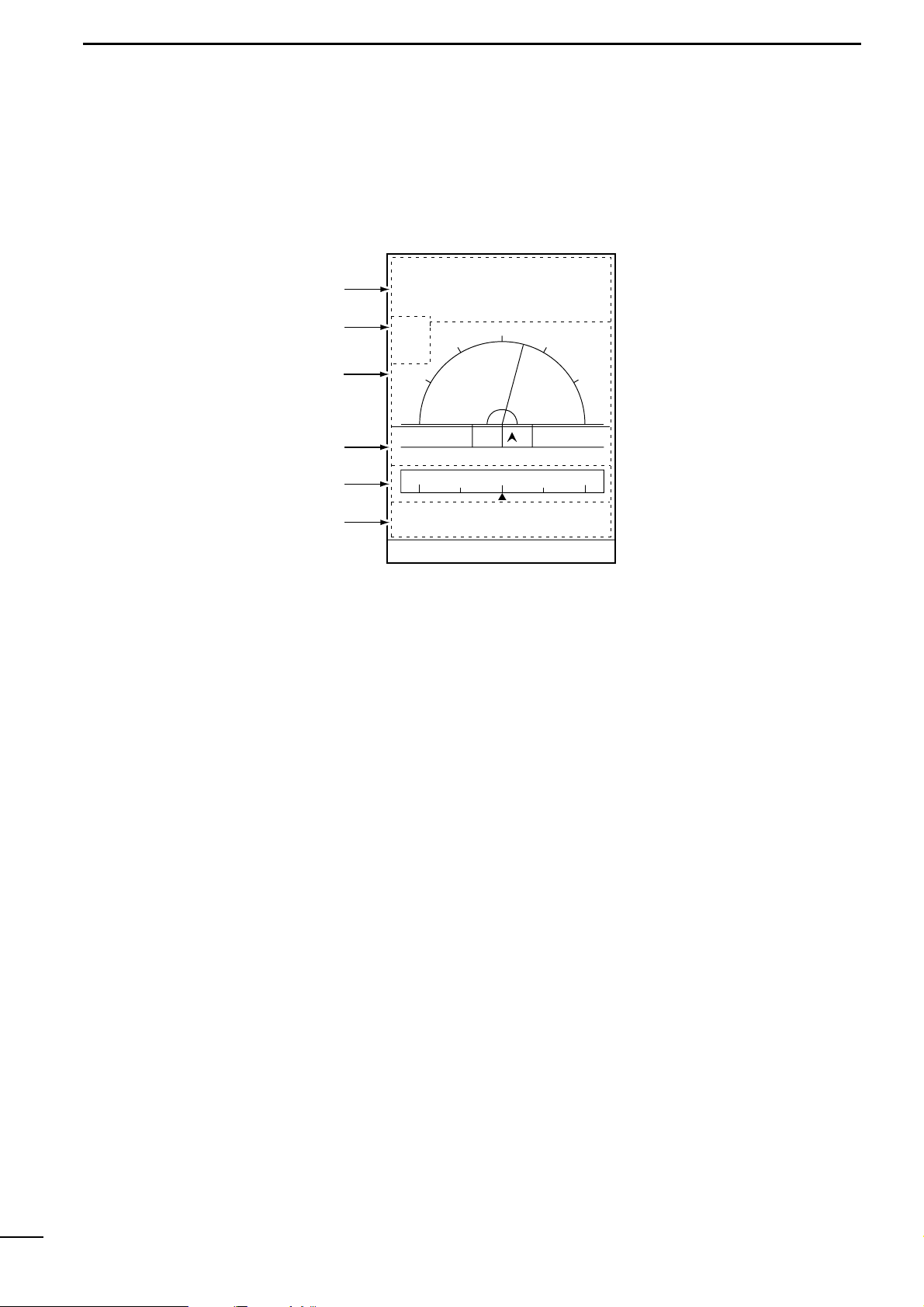
(1)-3 Navigation monitor screen
z Monitor
x Alarm indication
c Azimuth deviation
v Distance deviation
b Compass
n Ship position
This field shows navigation data including the destination No., the destination
azimuth, the distance to the destination, and the time to arrive the destination.
Alarms that can be displayed in this field include shoal alarm, depth alarm or fish
alarm for the fishfinder mode, and arrival alarm or range alarm for the plotter mode.
This field shows the current ship azimuth graphically (with a green line) and n umerically on the assumption that the destination azimuth is zero degree.
Note that, although the deviation of the ship azimuth from the destination azimuth
exceeds 90 degrees, the reading remains 90 degrees.
This field shows the deviation out of course in distance graphically and numerically.
When alarm limits are set with the alarm function, they are displayed with red lines
on the screen.
This field shows the direction to which the ship is being navigated.
This field shows the current ship position in latitude/longitude.
60゜
90゜
30゜
15゜R
30゜
0゜
60゜
90゜
N
E
W
NW NE
0°T 12KT 54.3°F
ARRV
ALRM
FISH
ALRM
80.0 FT
345°
14:25
01:05
15:30
TIME
TTG
ETA
15:30TTFD
No. 1
10.45NM
10.45NM
W P
D/D
C/D
D/FD
LON
LAT
DEVIATION
0.03
NM
134°01.000E
34°18.000N
z
x
c
v
n
b
Page 19
16
1
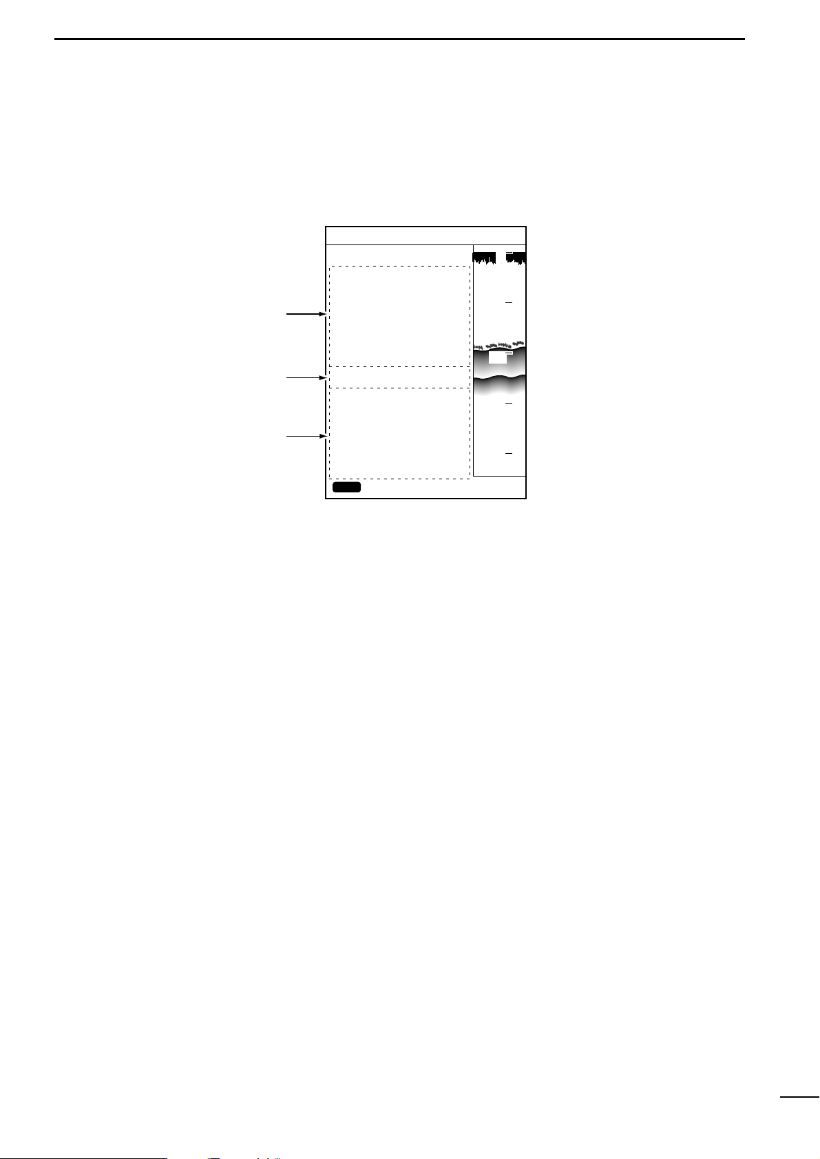
r PLOTTER MODEq AVAILABLE SCREENS AND INDICATIONS
z Satellite
x DOP
c DGPS information
This field shows and locates the navigational satellites that the system is being
tracked.
This field shows the geometrical arrangement of the navigational satellites and the
ship in the form of DOP (Dilution Of Precision) ranging from 0.00 to 99.99 (☞ P. 38).
The lower this value is, the better the geometrical arrangement is for the system to
receive signals from the satellites.
This field shows DGPS positioning information.
(1)-4 Positioning Inf ormation screen
0
10
20
30
40
DGPS34゚18.000N135゚01.000E
POSITIONING INFO
SAT# S/N BRG ELV
DOP
DGPS INFOMATION
RD-200
Rev.1.1
FREQUENCY 283.5
kHz
BAUD RATE 200
S/N 00
1.50
BACK
12 50 0 81
15 45 90 79
02 40 180 56
16 52 270 63
20 60 45 30
22 30 135 10
10 56 225 25
09 63 315 44
CLR
80.0FT
z
x
c
Page 20
17
2
r PLOTTER MODEq COASTLINE DATA MANIPULATION
Å 16 reduced scales
ı Ship-centering mode
(2)-1 Zooming in or out coastline images
The coastline image on the screen can be zoomed in or out to 0.125/256 NM
per dot to 4096/256 NM per dot (/ to ⁄5). See p. 30 for over zoom function.
The zooming center may be the ship position or the cross hair cursor position.
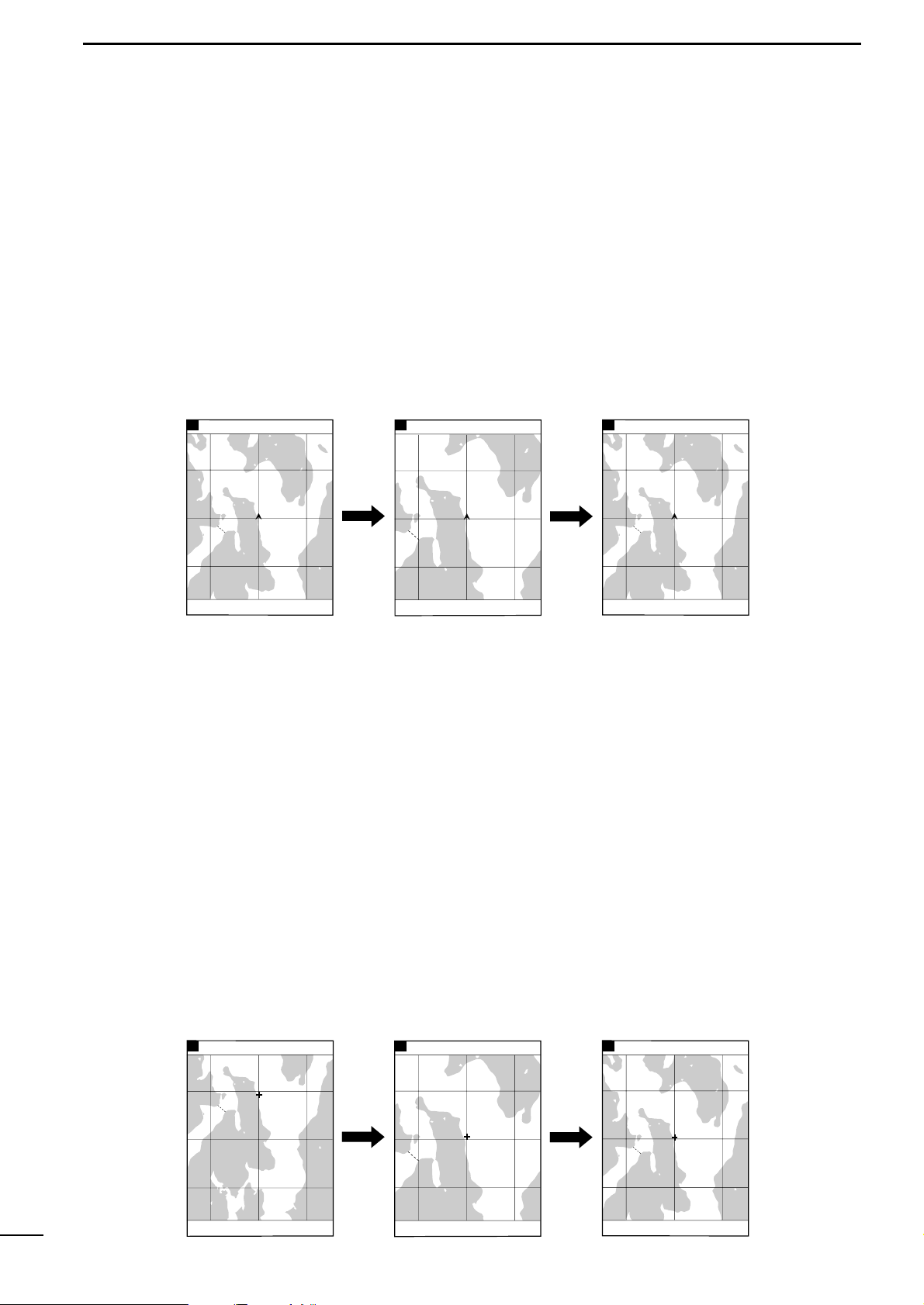
In this mode, the coastline image is zoomed in or out while the current ship
mark is centered on the screen.
When the cross hair cursor is not active, pressing the [ZOOM-IN] or [ZOOM-OUT]
key causes zooming operation to be done in this mode.
In this mode, the coastline image is zoomed in or out while the cross hair cursor position is centered on the screen.
q Press [UP]/[DOWN] or [LEFT]/[RIGHT] key to activate the cross hair cursor on
the screen.
w Using the [UP]/[DOWN] or [LEFT]/[RIGHT] k ey, move the cross hair cursor to the
desired position on the screen.
Using the [UP]-[LEFT] or [UP]-[RIGHT] key combination allows you to move the
cross hair cursor to the upper left of right.
Using the [DOWN]-[LEFT] or [DOWN]-[RIGHT] key combination allows you to
move the cross hair cursor to the lower left or right.
* When the cross hair cursor reaches a screen edge, the coastline image is
scrolled.
e Use the [ZOOM-IN] or [ZOOM-OUT] key to enlarge or reduce the image to the
desired scale in cursor-centering mode.
* When you press the [SHIP] key in cursor-centering mode, the cross hair cursor
disappears and the system goes to the ship-centering mode.
Ç Cursor-centering mode
8
DGPS34゚18.000N135゚01.000E
10
DGPS34゚18.000N135゚01.000E
10
DGPS34゚18.000N135゚01.000E
Press the [ZOOM-IN] key
to zoom in the image in
ship-centering mode.
Press the [ZOOM-OUT] key
to zoom out the image in
ship-centering mode.
The cross hair cursor is
not displayed.
80.0 FT0°T 12KT 54.3°F
RANGE 128
80.0 FT0°T 12KT 54.3°F
RANGE 32
80.0 FT0°T 12KT 54.3°F
RANGE 128
Press the [ZOOM-IN] key
to zoom in the image in
cursor-centering mode.
Press the [ZOOM-OUT] key
to zoom out the image in
cursor-centering mode.
The cross hair cursor is
activated.
80.0 FT0°T 12KT 54.3°F
RANGE 128
80.0 FT0°T 12KT 54.3°F
RANGE 32
80.0 FT0°T 12KT 54.3°F
RANGE 128
8
DGPS34゚18.000N135゚01.000E
10
DGPS34゚18.000N135゚01.000E
10
DGPS34゚18.000N135゚01.000E
Page 21
18
2
r PLOTTER MODEq COASTLINE DATA MANIPULATION
(2)-2 Ship-centering mode
| Manual operation (when the
cross hair cursor is active)
(2)-3 Displaying the latitude
and longitude lines
In ship-centering mode, the coastline image is automatically adjusted so that
the ship is always at the center of the screen.
The system defaults to the ship-centering mode.
If the ship mark is missing from the screen on which the cross hair cursor is active,
pressing the [SHIP] key allows the system to go to the ship-centering mode, where
the cross hair cursor disappears and the ship mark is centered on the screen.
A ROM card contains coastline data consisting of at least two screens. If a ROM
card (a NAVIONICS
®
Electronic Chart) is not inser ted into the card slot, no coast-
line data is displayed.
The loxodromic latitude and longitude lines can be displayed on the coastline screen.
The color of these lines can be selected from seven options.
q Press the [MENU] key.
The Main Menu screen will appear.
w Select “Screen Setting” using the [UP] or [DOWN] key and press the [SET] key.
The Screen Setting screen will appear.
e Select “GRID” using the [UP] or [DOWN] key and press the [SET] key.
The selected menu item turns blue.
t Move to the color field using the [LEFT] key.
The color field is highlighted in yellow.
y Select the desired color from among available colors (White (WHIT), Yellow
(YELL), Light blue (LBLU), Purple (PURP), Red, Green (GREE), Blue) and
press the [SET] key.
The color of the latitude/longitude lines changes to the selected option.
* If you do not want to display the latitude/longitude lines on the screen, select
“OFF” and press the [SET] key.
u When you finish setting, press the [MENU] key.
The previous screen appears.
GPS34゚18.000N135゚01.000E
5
¡Main Menu screen ¡Screen Setting screen
GPS34゚18.000N135゚01.000E
5
MAIN MENU
SCREEN SETTING
DISP MODE
BKG COLOR
LAND
SEA
NAME
D CON≦ 5m
D CON=10m
D CON≧20m
LIGHT
GRID
DISP MAPS
1
2
BLUE
YELL CSLN
BLUE
WHIT OFF
LBLU OFF
LBLU OFF
LBLU OFF
RED OFF
BLUE OFF
WHIT OFF
CLR
SOUNDER MENU
PLOTTER MENU
POSITIONING MENU
ALARM MENU
SCREEN SETTING
ENT
SET
CANC
SEL
80.0FT
CLR
ENT
SET
BACK
SEL
80.0FT
Page 22
19
2
r PLOTTER MODEq COASTLINE DATA MANIPULATION
(2)-4 Measuring the distance
and azimuth between two
points
Å Measurement between the ship
mark and the cursor position
Using the cross hair cursor permits you to measure the distance and azim uth
between two points easily.
The distance and azimuth that can be measured are between the ship mark and
the cursor position or between two points specified with the cursor.
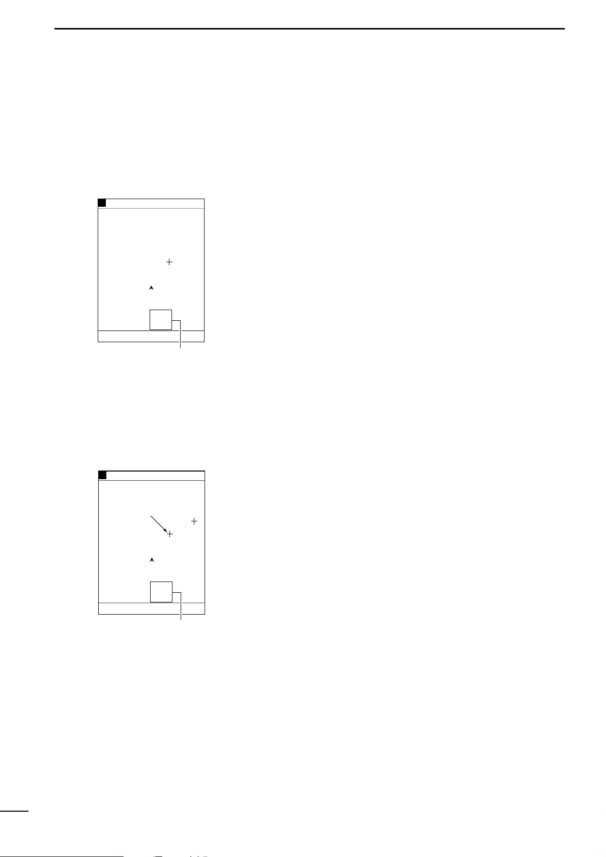
q Press the [UP]/[DOWN] or [LEFT]/[RIGHT] key to activate the cross hair cursor
(in light blue).
The cursor position is indicated at the lower left of the screen.
* When the cross hair cursor is activated, the auto ship-centering mode is can-
celed.
w Using the [UP]/[DOWN] or [LEFT]/[RIGHT] k ey, move the cross hair cursor to the
desired position.
Using the [UP]-[LEFT] or [UP]-[RIGHT] key combination allows you to move the
cross hair cursor to the upper left of right.
Using the [DOWN]-[LEFT] or [DOWN]-[RIGHT] key combination allows you to
move the cross hair cursor to the lower left or right.
* When the cross hair cursor reaches a screen edge, the coastline image is
scrolled.
e The distance between the ship mark and the cursor position and the azimuth of
the cursor position relative to the ship mark are displayed in the cursor position
field. When the ship mark coincides with the cursor position, a message indicating the ship reaches the cursor position is displayed in this field.
GPS34゚18.000N135゚01.000E
6
Cursor position field where
the distance and azimuth
between the ship and the
cursor position are displayed
80.0 FT0°T 12KT 54.3°F
34°20.000N
135°02.500E
27°
2.35
NM
0:15
RANGE 8
80.0 FT0°T 12KT 54.3°F
GPS34゚18.000N135゚01.000E
6
Cursor position field where
the distance and azimuth
between two points are displayed
Subcursor
34°21.000N
135°04.400E
60°
1.93
NM
0:12
RANGE 8
q Press the [UP]/[DOWN] or [LEFT]/[RIGHT] key to activate the cross hair cursor
(in light blue).
w Using the [UP]/[DOWN] or [LEFT]/[RIGHT] k ey, move the cross hair cursor to the
desired first point.
e Press the [SET] key.
The first point (subcursor position) turns red.
The distance and azimuth readings in the cursor position field will also turn red.
r Using the [UP]/[DOWN] or [LEFT]/[RIGHT] key, move the cross hair cursor (light
blue) to the desired second point.
* Pressing the [SET] key causes the subcursor to turn light blue, allowing you to
change the subcursor position.
t The distance between the two points and the azimuth of the light b lue cursor rel-
ative to the red subcursor are displayed in the cursor position field.
y When you finish measurement, press the [CLR] key.
The subcursor will go off.
ı Measurement between two
points specified with the cursor
Page 23
20
3
r PLOTTER MODEq ROUTE REGISTRATION AND EDIT
(3)-1 Registering and editing navigation routes
You can register up to 20 navigation routes, each of which consists of up to
50 points.
q Press the [MENU] key.
The Main Menu screen will appear.
w Select “Plotter Menu” using the [UP] or [DOWN] key and press the [SET] key.
The Plotter Menu screen will appear.
e Select “Route Enter/Edit” using the [UP] or [DO WN] k ey and press the [SET] k ey.
The Route Enter/Edit screen will appear.
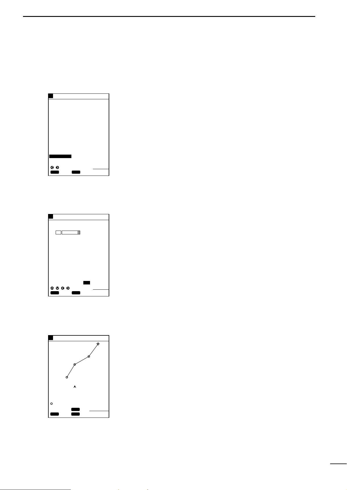
r Select “ENTER/EDIT” using the [LEFT] or [RIGHT] ke y and press the [SET] key.
This will allow you to select a route, and route No. 1 will currently be highlighted
in yellow.
t Using the [UP] or [DOWN] key, select the route No. you want to register.
* Pressing the [RIGHT] key permits you to go to the next page (route Nos. 11–20)
of the Route Enter/Edit screen. To return to the previous page (route Nos.
1–10), press the [LEFT] key.
y Press the [SET] key.
The character list will be displayed at the bottom of the screen and END be highlighted in yellow.
* The selected route No. will be displayed in the corresponding comment field.
The contents in the comment field can be overwritten and changed.
u Select a character from the character list using the [UP]/[DOWN] or
[LEFT]/[RIGHT] key and press the [SET] key.
Each time the [SET] key is pressed, the selected character is entered in the
comment field.
* A comment such as a user-defined route name of up to eight characters can be
entered in each comment field.
i Select “END” and press the [SET] key.
The coastline screen will appear.
o Move the cross hair cursor to the beginning point of the route using the
[UP]/[DOWN] or [LEFT]/[RIGHT] key and press the [SET] key.
Move the cross hair cursor to the next turning point and press the [SET] key.
* Up to 50 tur ning points can be registered per route.
* Sections between registered tur ning points are indicated as blue solid lines.
!0 When you finish route registration, press the [MENU] key.
The routes are registered, and you will return to the coastline screen.
GPS34゚18.000N135゚01.000E
5
Move the cross hair cursor to
a turning point and press the
[SET] key. Repeat this
operation to set a route.
34°23.752N
135°01.792E
27°
2.89
NM
0:25
2
1
3
4
GPS34゚18.000N135゚01.000E
5
GPS34゚18.000N135゚01.000E
5
Enter a comment and select
END; then press the [SET] key.
Select Route Enter/Edit and
press the [SET] key.
¡Route Enter/Edit screen
¡Comment Entry screen
¡Route Registration screen
CLR
ENT
SET
BACK
SEL
80.0FT
CLR
SET
SET
CANC
SEL
80.0FT
80.0FT
ROUTE ENTER/EDIT
ROUTE ENTER/EDIT
NO.
1
2
3
4
5
6
7
8
9
10
ENTER/EDIT ERS ERSALL
NO.
1 ROUTE 1
2
3
4
5
6
7
8
9
10
" # END
ABCDEFGHIJKLMNOPQRS
TUVWXYZ 0123456789
abcdefghijklmnopqrs
tuvwxyz .,!#$%&´-()
CLR
SET
SET
EXIT
MENU
CANC
Å Registering navigation routes
Page 24
21
3
r PLOTTER MODEq ROUTE REGISTRATION AND EDIT
ı Editing navigation routes
| Extending a navigation route
| Clearing turning points
The procedure of editing a registered route (extending a route or clearing
turning points of the route) is as follows.
q Select the route you want to extend according to the instruction in “Å
Registering navigation routes” on the previous page.
* The selected route is highlighted in blue.
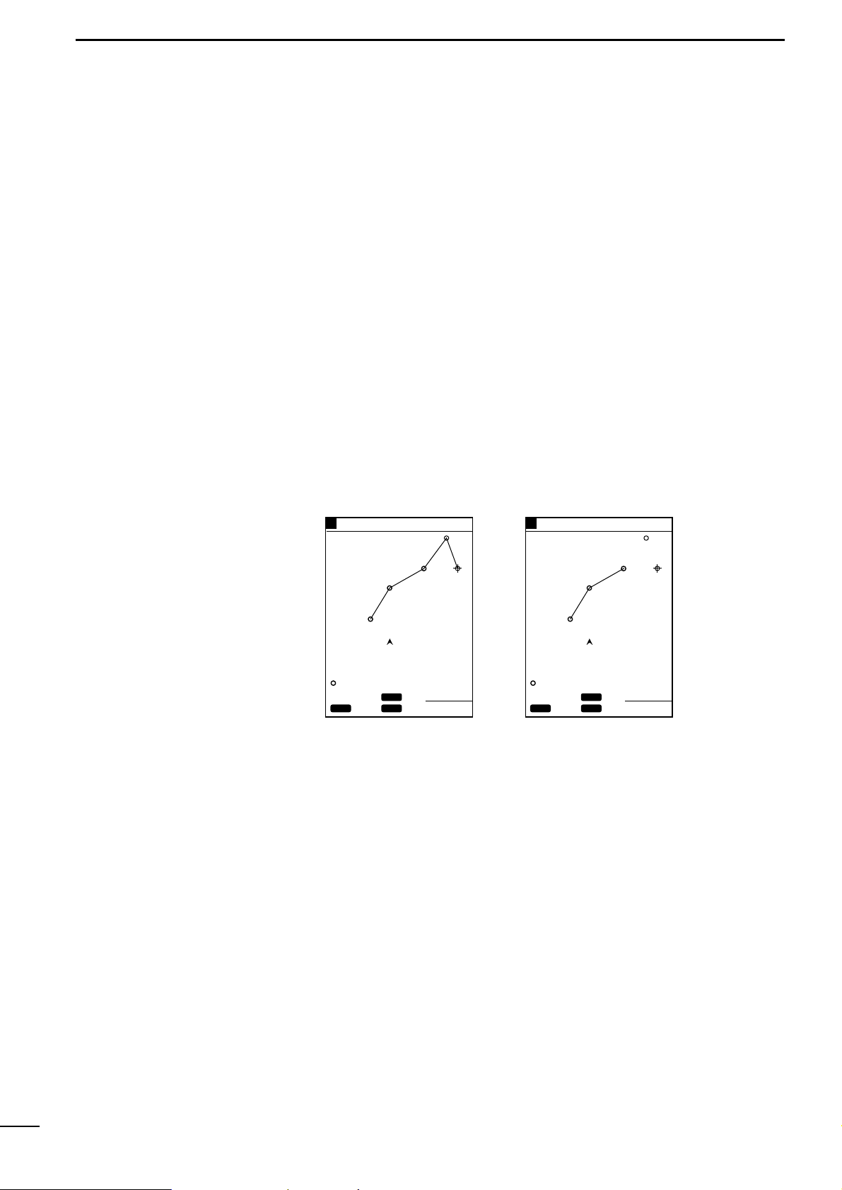
w Move the cross hair cursor to the point to which you want to extend the route
using the [UP]/[DOWN] or [LEFT]/[RIGHT] key, and press the [SET] key.
* Up to 50 tur ning points can be registered per route.
e The route extension is highlighted in blue.
r When you finish extending the route, press the [MENU] key.
The route extension is registered, and you will return to the coastline screen.
Pressing the [CLR] key during extending a route clears the last turning point
registered (the mark is not cleared).
Repeat this operation until all the turning points you want to clear are cleared.
Clearing all the turning points of a route results in the route itself being cleared.
GPS34゚18.000N135゚01.000E
5
Move the cross hair cursor to
the desired point and press
the [SET] key. The route is
extended to the point.
Each time the [CLR] key is
pressed, a turning points is
cleared in descending order
of its No.
¡Extending a route
2
1
3
4
5
GPS34゚18.000N135゚01.000E
5
¡Clearing turning points
2
1
3
CLR
SET
SET
EXIT
MENU
CANC
80.0FT
CLR
SET
SET
EXIT
MENU
CANC
80.0FT
34°23.752N
135°01.792E
37°
3.54
NM
0:25
34°23.752N
135°01.792E
37°
3.54
NM
0:25
Page 25
22
3
r PLOTTER MODEq ROUTE REGISTRATION AND EDIT
(3)-2 Clearing a route
The procedure of clearing a route is as follows.
q Press the [MENU] key.
The Main Menu screen will appear.
w Select “Plotter Menu” using the [UP] or [DOWN] key and press the [SET] key.
The Plotter Menu screen will appear.
e Select “Route Enter/Edit” using the [UP] or [DO WN] k ey and press the [SET] k ey.
The Route Enter/Edit screen will appear.
r Select “ERS” (erase) or “ERSALL” (erase all) using the [LEFT] or [RIGHT] key
and press the [SET] key.
When you select “ERS”, route No. 1 will be highlighted in yellow.
* When you select “ERSALL”, proceed with step i below.
t Using the [UP] or [DOWN] key, select the route No. you want to clear.
* Pressing the [RIGHT] key permits you to go to the next page (route Nos. 11–20)
of the Route Enter/Edit screen. To return to the previous page (route Nos.
1–10), press the [LEFT] key.
y Press the [SET] key.
A message will appear at the bottom of the screen, indicating the route No. you
selected is going to be cleared.
u Press the [SET] key again to clear the route.
i When you select “ERSALL” in step r above:
Press the [SET] key.
A message will appear at the bottom of the screen, indicating all the registered
routes are going to be cleared.
o Press the [SET] key again to clear all the routes.
GPS34゚18.000N135゚01.000E
5
Select ERS and press the
[SET] key.
Select the route No. you want
to clear and press the [SET] key.
Press the [SET] key, and the
selected route is cleared.
¡Route Enter/Edit screen
GPS34゚18.000N135゚01.000E
5
¡Selecting a route No.
GPS34゚18.000N135゚01.000E
5
¡Clearing the route
CLR
ENT
SET
BACK
SEL
80.0FT
ROUTE ENTER/EDIT
NO.
1 ROUTE 1
2
3
4
5
6
7
8
9
10
ENTER/EDIT ERS ERSALL
CLR
SET
SET
CANC
SEL
PAGE
80.0FT
ROUTE ENTER/EDIT
NO.
1 ROUTE 1
2
3
4
5
6
7
8
9
10
ENTER/EDIT ERS ERSALL
CLR
OK
SET
CANC
80.0FT
ROUTE ENTER/EDIT
NO.
1 ROUTE 1
2
3
4
5
6
7
8
9
10
ERASE ROUTE 1 ?
CLR
OK
SET
CANC
80.0FT
ERASE ALL ROUTES ?
80.0FT
Select ERSALL and press the
[SET] key.
Press the [SET] key, and all
the routes are cleared.
¡Selecting all routes
¡Clearing all routes
CLR
ENT
SET
BACK
SEL
ENTER/EDIT ERS ERSALL
Page 26
23
3
r PLOTTER MODEq ROUTE REGISTRATION AND EDIT
(3)-3 Character list
z Character list
x Spaces
c Cursor movement directions
v END
The character list appears on the Route Enter/Edit screen during route No.
selection, and is used for comment entry.
The character list is a list of characters used for comment entry.
Select a character from the character list using the [UP]/[DOWN] or
[LEFT]/[RIGHT] key and press the [SET] key.
The selected character is entered in the comment field of the selected route No.
When a space is selected and the [SET] key is pressed, a space is entered in overwrite mode in the comment field of the selected route No.
The cursor moves to the arrow direction you specified here .
Select the direction in which you want to move the cursor using the [UP]/[DOWN]
or [LEFT]/[RIGHT] key and press the [SET] key.
Use this command when you finish or abort comment entry.
Select “END” using the [UP]/[DOWN] or [LEFT]/[RIGHT] key and press the [SET]
key .
You will exit from the character list screen.
* Pressing the [CLR] key also allows you to exit from the character list screen, irre-
spective of what is highlighted in yellow.
" # END
ABCDEFGHIJKLMNOPQRS
TUVWXYZ 0123456789
abcdefghijklmnopqrs
tuvwxyz
.,
!#$%&
´
-()
z
cvx
Page 27

24
4
r PLOTTER MODEq MARK MANIPULATION
(4)-1 Registering marks
Å Registration of marks from the
Plotter Menu screen
Navigational reference points, such as the destination point and turning
points, can be indicated with marks. These marks will be helpful for destination navigation and route navigation.
They can be registered in two ways: from the Plotter Menu screen or on the coastline screen.
q Press the [MENU] key.
The Main Menu screen will appear.
w Select “Plotter Menu” using the [UP] or [DOWN] key and press the [SET] key.
The Plotter Menu screen will appear.
e Select “Mark Enter/Erase” using the [UP] or [DOWN] key and press the [SET]
key .
The Mark Enter/Erase screen will appear.
r Select “ENTER” using the [UP] or [DOWN] key and press the [SET] key.
The system is ready for mark registration and the first digit of the latitude setting
field is highlighted in yellow.
t Select digits in the latitude setting field using the [LEFT] or [RIGHT] key, enter a
numerical value and specify the latitude direction, N (North) or S (South), using
the [UP] or [DOWN] key, and then press the [SET] key.
The first digit of the longitude setting field is highlighted in yellow.
y Select digits in the longitude setting field using the [LEFT] or [RIGHT] key, enter
a numerical value and specify the longitude direction, E (East) or W (West),
using the [UP] or [DOWN] key, and then press the [SET] key.
One of 12 marks will appear at the bottom of the screen.
u Select the desired mark using the [UP] or [DOWN] key and the desired color of
the mark (seven colors selectable) using the [LEFT] or [RIGHT] key, and then
press the [SET] key.
The character list will appear at the bottom of the screen and END is highlight-
ed in yellow.
i Select a character from the character list to name the mark, and then press the
[SET] key.
Each time the [SET] key is pressed, the selected character is entered in the
comment field.
* A comment such as a user-defined mar k name of up to eight characters can be
entered in each comment field.
o Select “END” and press the [SET] key.
The mark is now registered.
* Repeat steps t to o as required.
ENTER
LAT 34°25.123N
LON 135°10.456E
ERASE ALL
5
Enter the latitude and longitude
and press the [SET] key.
Select the desired mark and
press the [SET] key.
Enter the mark name and
press the [SET] key.
5
¡Mark Enter/Erase screen ¡Selecting the mark to be
used
¡Entering the user-defined
mark name
GPS34゚18.000N135゚01.000E GPS34゚18.000N135゚01.000E
GPS34゚18.000N135゚01.000E
5
CLR
SET
SET
CANC
ADJ
SEL
80.0FT
MARK ENTER/ERASE
ENTER
LAT 34°25.123N
LON 135°10.456E
ERASE ALL
CLR
SET
SET
CANC
TYPE
COL
80.0FT
MARK ENTER/ERASE
ENTER
LAT 34°25.123N
LON 135°10.456E
Point1
ERASE ALL
CLR
SET
SET
CANC
80.0FT
MARK ENTER/ERASE
SEL
" # END
ABCDEFGHIJKLMNOPQRS
TUVWXYZ 0123456789
abcdefghijklmnopqrs
tuvwxyz .,!#$%&´-()
Page 28

25
4
r PLOTTER MODEq MARK MANIPULATION
ı Registration of the current ship
position mark on the coastline
screen
To indicate the current ship position with a mark, proceed as follows.
q Press the [MARK] key.
One of 12 marks will appear at the bottom of the screen.
w Select the desired mark using the [UP] or [DOWN] key and the desired color of
the mark (seven colors selectable) using the [LEFT] or [RIGHT] key.
* If no comment is required, press the [SET] key. This brings the mark registra-
tion operation to an end.
e Press the [MENU] key.
The character list will appear at the bottom of the screen, on which “END” is
highlighted in yellow.
r Select a character from the character list using the [UP]/[DOWN] or
[LEFT]/[RIGHT] key and press the [SET] key.
Each time the [SET] key is pressed, the selected character is entered in the
comment field.
* A comment of up to eight characters can be entered in each comment field.
t Select “END” and press the [SET] key.
The selected mark and entered comment are placed at the current ship position.
GPS34゚18.000N135゚01.000E
5
GPS34゚18.000N135゚01.000E
5
GPS34゚18.000N135゚01.000E
5
Move the cross hair cursor to
the desired position.
Select the desired mark and
its color.
Enter a comment and select
“END”; then press the [SET] key.
¡Selecting the desired mark
and color
¡Activating the cross hair
cursor
¡Entering a comment
80.0
FT0°T 12KT 54.3°F
RANGE 4
80.0
FT
80.0
FT
34°18.000N
135°01.000E
27°
2.89
NM
0:15
34°18.000N 27°
CLR
SET
SET
CANC
SEL
" # END
ABCDEFGHIJKLMNOPQRS
TUVWXYZ 0123456789
abcdefghijklmnopqrs
tuvwxyz .,!#$%&´-()
CLR
SET
SET
CANC
TYPE
COL
COMMENT : Point2
COM
MENU
q On the coastline screen, press the [UP]/[DOWN] or [LEFT]/[RIGHT] key to acti-
vate the cross hair cursor.
w Using the [UP]/[DOWN] or [LEFT]/[RIGHT] key, move the cross hair cursor to
any desired position on the screen.
e Press the [MARK] key.
One of 12 marks will appear at the bottom of the screen.
r Select the desired mark using the [UP] or [DOWN] key and the desired color of
the mark (seven colors selectable) using the [LEFT] or [RIGHT] key.
* If no comment is required, press the [SET] key. This brings the mark registra-
tion operation to an end.
t Press the [MENU] key.
The character list will appear at the bottom of the screen, on which “END” is
highlighted in yellow.
y Select a character using the [UP]/[DOWN] or [LEFT]/[RIGHT] key and press the
[SET] key.
Each time the [SET] key is pressed, the selected character is entered in the
comment field.
* A comment of up to eight characters can be entered in each comment field.
u Select “END” and press the [SET] key.
The selected mark and entered comment are placed at the cross hair cursor
position on the screen.
Ç Registration of marks located at
any position on the coastline
screen
Page 29

26
4
r PLOTTER MODEq MARK MANIPULATION
(4)-2 Clearing marks
Å Clearing marks on the coastline
screen
Marks cannot be cleared during
destination or route navigation.
T o clear registered marks separatel y, you must enter the coastline screen. T o
clear all registered mark at a time, you must enter the Plotter Menu screen.
Note that marks placed along a navigation route, such as turning point marks, cannot be cleared unless turning points of the route are canceled (☞ P. 21) or the route
is canceled (☞ P. 22).
To clear registered marks separately, proceed as follows
q On the coastline screen, press the [UP]/[DOWN] or [LEFT]/[RIGHT] key to acti-
vate the cross hair cursor.
w Using the [UP]/[DOWN] or [LEFT]/[RIGHT] k ey, move the cross hair cursor to the
mark you want to clear.
The comment of the mark will be also displayed.
* If the mar k appears to coincide with the cross hair cursor because of the scale
to which the coastline image is displayed, zoom in the image before clearing the
mark.
e Press the [CLR] key.
A message indicating the mark is going to be cleared will appear at the bottom
of the screen.
* If you do not want to clear the mark, press the [CLR] key again.
r Press the [SET] key.
The mark will be cleared.
Note that, while the cross hair cursor is not active on the screen, the current
ship position mark is not cleared.
GPS34゚18.000N135゚01.000E
5
Move the cross hair cursor until it
coincides with the mark you want
to clear, and press the [CLR] key.
¡Clearing marks on the
coastline screen
Mark position
data
80.0 FT
CLR
OK
SET
CANC
ERASE THE MARK ?
34°18.000N
135°01.000E
Point2
27°
2.89
NM
0:15
5
Select “ERASE ALL” and press
the [SET] key.
¡Clearing marks from
the Plotter Menu screen
GPS34゚18.000N135゚01.000E
ENTER
LAT ° . N
LON ° . E
ERASE ALL
ERASE ALL MARKS ?
CLR
OK
SET
CANC
80.0FT
MARK ENTER/ERASE
To clear all registered marks at a time, proceed as follows.
q Press the [MENU] key.
The Main Menu screen will appear.
w Select “Plotter Menu” using the [UP] or [DOWN] key and press the [SET] key.
The Plotter Menu screen will appear.
e Select “Mark Enter/Erase” using the [UP] or [DOWN] key and press the [SET]
key .
The Mark Enter/Erase screen will appear.
r Select “Erase All” using the [UP] or [DOWN] key.
t Press the [SET] key.
A message will appear indicating all marks are going to be cleared.
y Press the [SET] key.
All marks will be cleared.
* To clear such marks that are placed along a route, cancel the route in advance.
ı Clearing marks from the Plotter
Menu screen
Page 30

27
5
r PLOTTER MODEq ROUTE NAVIGATION SETTING
(5)-1 Setting route navigation
Route navigation means that the ship is navigated via a number of registered
marks to the destination.
q Make sure that the navigation route has already been registered (☞ P. 20)
before commencing route navigation.
Failure to register the navigation route disables route navigation.
* Registration of a new navigation route needs an existing route or destination, if
any, to be canceled in advance (see section (5)-2).
w Press the [NAV] key.
The navigation selection screen will appear.
e Select “Route” using the [UP] or [DOWN] key and press the [SET] key.
The Route No. field, Outward/Homeward selection field, and comment field will
appear at the bottom of the screen.
r Select “Route No.” using the [UP] or [DOWN] key, select “GO” (Outward) or
“RTN” (Retur n; Homeward) voyage using the [LEFT] or [RIGHT] key, and then
press the [SET] key.
The route navigation screen will appear, at the bottom of which are displa y ed the
first destination No., the azimuth and distance to the destination, and the deviation out of course.
* On the coastline screen, the section between the current ship mark and the fist
destination No. is depicted by a green solid line. A purple solid line is used to
show each section thereafter.
Select “ROUTE” and press
the [SET] key.
Select route No. and “GO” or
“RTN” voyage and press the
[SET] key.
¡Selecting a route No.
¡Route navigation screen
¡Navigation screen
2
1
0
3
5
DGPS34゚18.000N135゚01.000E
CLR
SET
SET
CANC
80.0FT
NAV
SEL
DESTINATN
ROUTE
CLR
SET
SET
CANC
80.0FT
ROUTE
ROUTE 1
SEL
1 GO
GO/RTN
TO WP 1
0.19NM 315°
80.0 FT0°T 5.5KT 54.3°F
RANGE 4
The solid line indicating the first section of route navigation defaults to
green. If you want to expand the monitor range to the second section
between the first and second destination Nos. (if you want to change the
color of the solid line for the second section from purple to green), proceed
as follows.
q On the coastline screen, press the [UP] or [DOWN] ke y to activate the cross hair
cursor.
w Using the [UP]/[DOWN] or [LEFT]/[RIGHT] key, move the cross hair cursor until
its intersection coincides with the mark of the second destination No.
e Press the [NAV] key.
The purple solid line for the second section will turn green.
To cancel route navigation, proceed as follows.
q On the coastline or combination screen, press the [NAV] key during route navi-
gation.
* Make sure that a mark along the route does not coincide with the cross hair cursor.
w A message indicating the current navigation is going to be canceled is display ed.
Press the [SET] key.
The current navigation will be canceled.
| Changing the monitor range
(5)-2 Canceling route
navigation
Press the [SET] key to cancel
the current navigation.
¡Navigation cancel screen
CLR
OK
SET
CANC
80.0FT
EXIT
THE NAVIGATION ?
Page 31

28
6
r PLOTTER MODEq DESTINATION NAVIGATION SETTING
(6)-1 Setting destination
navigation
Å Setting destination navigation
using existing registered marks
Destination navigation means that the ship is navigated from the current ship
position to the specified destination (within one section only).
Destination navigation is set on the coastline screen.
Registration of a new navigation section needs an existing route or destination, if
any, to be canceled in advance.
q On the coastline or combination screen, press the [NAV] key.
The navigation selection screen will appear.
w Select “DESTINATN” (destination) using the [UP] or [DOWN] key and press the
[SET] key.
e The cross hair cursor will appear at the center of the screen.
Position data of the cross hair cursor is displayed at the bottom of the screen.
r Using the [UP]/[DOWN] or [LEFT]/[RIGHT] key, move the cross hair cursor until
its intersection coincides with the desired one of existing registered marks.
Information on the mark, such as a comment, is displayed at the bottom of the
screen.
t Press the [SET] key.
The destination navigation screen will appear, on which the section betw een the
current ship position and the destination mark is depicted by a green solid line.
At the bottom of the screen are displayed the destination No., the azimuth and
distance to the destination, and the deviation out of course.
Press the [SET] key to cancel
the current navigation.
¡Navigation cancel screen
CLR
OK
SET
CANC
80.0FT
EXIT
THE NAVIGATION ?
Select “DESTINATN” and
press the [SET] key.
Select a mark and press the
[SET] key.
¡Navigation screen
¡Destination navigation screen
CLR
SET
SET
CANC
80.0FT
NAV
SEL
DESTINATN
ROUTE
CLR
SET
SET
CANC
80.0FT
DESTINATN
34°18.000N
135°01.000E
Point2
27°
2.89
NM
0:15
1
0
¡Destination navigation screen
5
DGPS34゚18.000N135゚01.000E
Move the cursor to the desired
position and press the [SET] key.
TO WP 1
1.40NM 50°
80.0 FT0°T 5.5KT 54.3°F
RANGE 4
34゚19.000N
135゚02.300E
50°
1.40
NM
0:15
q On the coastline or combination screen, press the [NAV] key.
The navigation selection screen will appear.
w Select “DESTINATN” (destination) using the [UP] or [DOWN] key and press the
[SET] key.
e The cross hair cursor will appear at the center of the screen.
Position data of the cross hair cursor is displayed at the bottom of the screen.
r Using the [UP]/[DOWN] or [LEFT]/[RIGHT] key, move the cross hair cursor so
that its intersection reaches the desired position.
t Press the [SET] key.
A new mark (purple “$”) is automatically registered.
The destination navigation screen will appear, on which the section betw een the
current ship mark and the specified destination mark is depicted by a green solid
line.
At the bottom of the screen are displayed the destination No., the azimuth and
distance to the destination, and the deviation out of course.
ı Setting destination navigation
using a newly registered mark
(6)-2 Canceling destination
navigation
To cancel destination navigation, proceed as follows.
q On the coastline or combination screen, press the [NAV] key during destination
navigation.
w A message indicating the current navigation is going to be canceled is display ed.
Press the [SET] key.
The current navigation will be canceled.
Page 32

29
7
r PLOTTER MODEq TRACK MANIPULATION
(7)-1 Setting the track color
(7)-2 Changing the tracking
interval
There are seven user-selectable colors of the track.
Set the track color as follows.
q Press the [MENU] key.
The Main Menu screen will appear.
w Select “Plotter Menu” using the [UP] or [DOWN] key and press the [SET] key.
The Plotter Menu screen will appear.
e Select “TRK COLOR” (track color) using the [UP] or [DOWN] key and press the
[SET] key.
The selected item turns blue.
r Move to the color setting field using the [LEFT] or [RIGHT] key.
The color field is highlighted in yellow.
t Select the desired color from among sev en colors (White (WHIT), Yellow (YELL),
Light blue (LBLU), Purple (PURP), Red, Green (GREE), Blue) using the [UP] or
[DOWN] key and press the [SET] key.
The track color is set as you selected.
y When you finish setting the track color, press the [MENU] key.
You will return to the previous screen.
The system stores and plots the track consisting of up to 5,000 points
through which the ship passed.
If the number of the points exceeds 5,000, excess track data is deleted in chronological order.
The track data is updated at specified tracking intervals.
Note that longer tracking (track update) intervals allow the system to co v er a longer
track, but may cause a lower resolution of the track image when zoomed in.
To change the tracking intervals, proceed as follows.
q Press the [MENU] key.
The Main Menu screen will appear.
w Select “Plotter Menu” using the [UP] or [DOWN] key and press the [SET] key.
The Plotter Menu screen will appear.
e Select “TRK STEP” (track step) using the [UP] or [DOWN] key and press the
[SET] key.
The selected item turns blue.
r Move to the setting field using the [LEFT] or [RIGHT] key.
The setting field is highlighted in yellow.
This field contains three setting items; the time interval, the unit of time, and the
distance interval.
* The unit of distance depends on the setting on the Setting Menu screen.
t Enter the desired time interval and unit of time, or the distance interval into the
setting field, and then press the [SET] key.
The change in tracking interval is saved.
y When you finish changing, press the [MENU] key.
You will return to the previous screen.
GPS34゚18.000N135゚01.000E
5
PLOTTER MENU
ROUTE ENTER/EDIT#
MARK ENTER/ERASE#
TRK COLOR
TRK STEP
TRK ERASE
HEADING
FRONT WIDE
OVER ZOOM
WHIT OFF
30S 1.00NM
ON OFF
ON OFF
ON OFF
80.0FT
CLR
SET
SET
CANC
ADJ
SEL
GPS34゚18.000N135゚01.000E
5
PLOTTER MENU
ROUTE ENTER/EDIT#
MARK ENTER/ERASE#
TRK COLOR
TRK STEP
TRK ERASE
HEADING
FRONT WIDE
OVER ZOOM
WHIT OFF
30S 1.00NM
ON OFF
ON OFF
ON OFF
CLR
SET
SET
CANC
ADJ
SEL
80.0FT
Page 33

30
7
r PLOTTER MODEq TRACK MANIPULATION
To clear the track on the screen after navigation, proceed as follows.
Note the following procedure loses any track data in the system. Make sure that
deletion of track data will cause no problem before commencing the procedure.
q Press the [MENU] key.
The Main Menu screen will appear.
w Select “Plotter Menu” using the [UP] or [DOWN] key and press the [SET] key.
The Plotter Menu screen will appear.
e Select “TRK ERASE” (track erase) using the [UP] or [DOWN] key and press the
[SET] key.
The selected item turns blue.
r A message will appear at the bottom of the screen, indicating the track data is
going to be cleared.
Press the [SET] key to clear the track data.
Press the [CLR] key to abort “clear” operation. You will return to the Plotter
Menu screen.
t Press the [MENU] key to return to the previous screen.
To set the heading vector, proceed as follows.
q Press the [MENU] key.
The Main Menu screen will appear.
w Select “Plotter Menu” using the [UP] or [DOWN] key and press the [SET] key.
The Plotter Menu screen will appear.
e Select “HEADING” using the [UP] or [DOWN] key and press the [SET] key.
The selected item turns blue.
r Select “ON” or “OFF” using the [LEFT] or [RIGHT] key and press the [SET] key.
The heading vector will appear when ON is selected.
t Press the [MENU] key to return to the previous screen.
To set the front wide function, proceed as follows.
q Press the [MENU] key.
The Main Menu screen will appear.
w Select “Plotter Menu” using the [UP] or [DOWN] key and press the [SET] key.
The Plotter Menu screen will appear.
e Select “FRONT WIDE” using the [UP] or [DOWN] key and press the [SET] key.
The selected item turns blue.
r Select “ON” or “OFF” using the [LEFT] or [RIGHT] key and press the [SET] key.
The heading area will displayed widely when ON is selected.
t Press the [MENU] key to return to the previous screen.
To set the over zoom function, proceed as follows.
q Press the [MENU] key.
The Main Menu screen will appear.
w Select “Plotter Menu” using the [UP] or [DOWN] key and press the [SET] key.
The Plotter Menu screen will appear.
e Select “OVER ZOOM” using the [UP] or [DOWN] key and press the [SET] key.
The selected item turns blue.
r Select “ON” or “OFF” using the [LEFT] or [RIGHT] key and press the [SET] key.
The all zoom ranges will become selectable when ON is selected.
(7)-3 Clearing the track
(7)-4 Setting the heading
vector
(7)-5 Setting the front wide
function
(7)-6 Setting the over zoom
function
GPS34゚18.000N135゚01.000E
5
PLOTTER MENU
ROUTE ENTER/EDIT#
MARK ENTER/ERASE#
TRK COLOR
TRK STEP
TRK ERASE
HEADING
FRONT WIDE
OVER ZOOM
ERASE THE TRACK ?
WHIT OFF
30S 1.00NM
ON OFF
ON OFF
ON OFF
CLR
OK
SET
CANC
80.0FT
GPS34゚18.000N135゚01.000E
5
PLOTTER MENU
ROUTE ENTER/EDIT#
MARK ENTER/ERASE#
TRK COLOR
TRK STEP
TRK ERASE
HEADING
FRONT WIDE
OVER ZOOM
WHIT OFF
30S 1.00NM
ON OFF
ON OFF
ON OFF
GPS34゚18.000N135゚01.000E
5
PLOTTER MENU
ROUTE ENTER/EDIT#
MARK ENTER/ERASE#
TRK COLOR
TRK STEP
TRK ERASE
HEADING
FRONT WIDE
OVER ZOOM
WHIT OFF
30S 1.00NM
ON OFF
ON OFF
ON OFF
GPS34゚18.000N135゚01.000E
5
PLOTTER MENU
ROUTE ENTER/EDIT#
MARK ENTER/ERASE#
TRK COLOR
TRK STEP
TRK ERASE
HEADING
FRONT WIDE
OVER ZOOM
WHIT OFF
30S 1.00NM
ON OFF
ON OFF
ON OFF
80.0FT
CLR
SET
SET
CANC
SEL
Page 34

31
8
r PLOTTER MODEq DATA COLOR SETTING
(8)-1 Setting colors of data on
screen
Å Specifying the color of land
ı Specifying the color of sea
Data stored on a NA VIONICS®Electronic Chart, including lights positions and
depth contours, can be displayed selectively.
The following explains how to specify colors of land, sea, place-names, depth contours, lights, and latitude/longitude lines.
The color of land can be selected from among seven available colors.
q Press the [MENU] key.
The Main Menu screen will appear.
w Select “Screen Setting” using the [UP] or [DOWN] key and press the [SET] key.
The Screen Setting screen will appear.
e Select “LAND” using the [UP] or [DOWN] key and press the [SET] key.
The selected item turns blue.
r Move to the color field or “CSLN” (coastline) field using the [LEFT] or [RIGHT]
key .
The field is highlighted in yellow.
* When moving to the color field, proceed with step t.
* When moving to “CSLN”, press the [SET] key.
Land will be contoured in the selected color. The inside of land remains the
same as sea in color.
t Select the desired color from among available colors (White (WHIT), Yellow
(YELL), Light blue (LBLU), Purple (PURP), Red, Green (GREE), Blue) using the
[UP] or [DOWN] key and press the [SET] key.
Land will be displayed in the selected color.
y When you finish setting the color of land, press the [MENU] key.
You will return to the previous screen.
The color of sea can be selected from among two available colors.
q Press the [MENU] key.
The Main Menu screen will appear.
w Select “Screen Setting” using the [UP] or [DOWN] key and press the [SET] key.
The Screen Setting screen will appear.
e Select “SEA” using the [UP] or [DOWN] key and press the [SET] key.
The selected item turns blue.
r Select “BLUE” or “BLK” (Black) using the [UP] or [DOWN] key and press the
[SET] key.
Sea is displayed in the selected color.
t When you finish setting the color of sea, press the [MENU] key.
You will return to the previous screen.
SCREEN SETTING
DISP MODE
BKG COLOR
LAND
SEA
NAME
D CON≦ 5m
D CON=10m
D CON≧20m
LIGHT
GRID
DISP MAPS
1
2
BLUE
YELL CSLN
BLUE
WHIT OFF
LBLU OFF
LBLU OFF
LBLU OFF
RED OFF
BLUE OFF
WHIT OFF
80.0FT
GPS34゚18.000N135゚01.000E
5
CLR
SET
SET
CANC
ADJ
SEL
SCREEN SETTING
DISP MODE
BKG COLOR
LAND
SEA
NAME
D CON≦ 5m
D CON=10m
D CON≧20m
LIGHT
GRID
DISP MAPS
1
2
BLUE
YELL CSLN
BLUE
WHIT OFF
LBLU OFF
LBLU OFF
LBLU OFF
RED OFF
BLUE OFF
WHIT OFF
80.0FT
GPS34゚18.000N135゚01.000E
5
CLR
SET
SET
CANC
SEL
Page 35

32
8
r PLOTTER MODEq DATA COLOR SETTING
Ç Specifying the color of place-
names
Î Specifying the color of depth
contours
´ Specifying the color of lights
The color of place-names can be selected from among seven available color s.
q Press the [MENU] key.
The Main Menu screen will appear.
w Select “Screen Setting” using the [UP] or [DOWN] key and press the [SET] key.
The Screen Setting screen will appear.
e Select “NAME” using the [UP] or [DOWN] key and press the [SET] key.
The selected item turns blue.
r Move to the color field using the [LEFT] or [RIGHT] key.
The color field will be highlighted in yellow.
t Select the desired color from among available colors (White (WHIT), Yellow
(YELL), Light blue (LBLU), Purple (PURP), Red, Green (GREE), Blue) using the
[UP] or [DOWN] key and press the [SET] key.
Place-names will be displayed in the selected color.
* When you select “OFF” and press the [SET] key , place-names are not displa y ed.
y When you finish setting the color of place-names, press the [MENU] key.
You will return to the previous screen.
The color of depth contour can be selected from among seven available colors.
q Press the [MENU] key.
The Main Menu screen will appear.
w Select “Screen Setting” using the [UP] or [DOWN] key and press the [SET] key.
The Screen Setting screen will appear.
e Select “D CON≦5m,” “D CON=10m” or “D CON≧20m” using the [UP] or
[DOWN] key and press the [SET] key. (D CON=Depth Contour)
The selected item turns blue.
r Move to the color field using the [LEFT] or [RIGHT] key.
The color field will be highlighted in yellow.
t Select the desired color from among available colors (White (WHIT), Yellow
(YELL), Light blue (LBLU), Purple (PURP), Red, Green (GREE), Blue) using the
[UP] or [DOWN] key and press the [SET] key.
Depth contour will be displayed in the selected color.
* When you select “OFF” and press the [SET] key, depth contour are not dis-
played.
y When you finish setting the color of depth contour, press the [MENU] key.
You will return to the previous screen.
The color of lights can be selected from among seven available colors.
q Press the [MENU] key.
The Main Menu screen will appear.
w Select “Plotter Menu” using the [UP] or [DOWN] key and press the [SET] key.
The Plotter Menu screen will appear.
e Select “LIGHT” using the [UP] or [DOWN] key and press the [SET] key.
The selected item turns blue.
r Move to the color field using the [LEFT] or [RIGHT] key.
The color field will be highlighted in yellow.
t Select the desired color from among available colors (White (WHIT), Yellow
(YELL), Light blue (LBLU), Purple (PURP), Red, Green (GREE), Blue) using the
[UP] or [DOWN] key and press the [SET] key.
Lights will be displayed in the selected color.
* When you select “OFF” and press the [SET] key, lights are not displayed.
y When you finish setting the color of lights, press the [MENU] key.
You will return to the previous screen.
SCREEN SETTING
DISP MODE
BKG COLOR
LAND
SEA
NAME
D CON≦ 5m
D CON=10m
D CON≧20m
LIGHT
GRID
DISP MAPS
80.0FT
GPS34゚18.000N135゚01.000E
5
CLR
SET
SET
CANC
1
2
BLUE
YELL CSLN
BLUE
WHIT OFF
LBLU OFF
LBLU OFF
LBLU OFF
RED OFF
BLUE OFF
WHIT OFF
ADJ
SEL
SCREEN SETTING
DISP MODE
BKG COLOR
LAND
SEA
NAME
D CON≦ 5m
D CON=10m
D CON≧20m
LIGHT
GRID
DISP MAPS
80.0FT
GPS34゚18.000N135゚01.000E
5
CLR
SET
SET
CANC
1
2
BLUE
YELL CSLN
BLUE
WHIT OFF
LBLU OFF
LBLU OFF
LBLU OFF
RED OFF
BLUE OFF
WHIT OFF
ADJ
SEL
SCREEN SETTING
DISP MODE
BKG COLOR
LAND
SEA
NAME
D CON≦ 5m
D CON=10m
D CON≧20m
LIGHT
GRID
DISP MAPS
80.0FT
GPS34゚18.000N135゚01.000E
5
1
2
BLUE
YELL CSLN
BLUE
WHIT OFF
LBLU OFF
LBLU OFF
LBLU OFF
RED OFF
BLUE OFF
WHIT OFF
CLR
SET
SET
CANC
ADJ
SEL
Page 36

Ï Specifying the color of map
border
˝ Specifying the display mode
33
8
r PLOTTER MODEq DATA COLOR SETTING
The color of map border can be selected from among seven available colors.
q Press the [MENU] key.
The Main Menu screen will appear.
w Select “Screen Setting” using the [UP] or [DOWN] key and press the [SET] key.
The Screen Setting screen will appear.
e Select “DISP MAPS” (display maps) using the [UP] or [DOWN] key and press
the [SET] key.
The selected item turns blue.
r Move to the color field using the [LEFT] or [RIGHT] key.
The color field will be highlighted in yellow.
t Select the desired color from among available colors (White (WHIT), Yellow
(YELL), Light blue (LBLU), Purple (PURP), Red, Green (GREE), Blue) using the
[UP] or [DOWN] key and press the [SET] key.
Map border will be displayed in the selected color.
* When you select “OFF” and press the [SET] key, map border are not displayed.
y When you finish setting the color of map border, press the [MENU] key.
You will return to the previous screen.
These color settings can be memorized and selected from two display
modes.
q Press the [MENU] key.
The Main Menu screen will appear.
w Select “Plotter Menu” using the [UP] or [DOWN] key and press the [SET] key.
The Plotter Menu screen will appear.
e Select “DISP MODE” (display mode) using the [LEFT] or [RIGHT] key and press
the [SET] key.
Color settings will be displayed in the memorized colors.
r When you finish selection, press the [MENU] key.
You will return to the previous screen.
SCREEN SETTING
DISP MODE
BKG COLOR
LAND
SEA
NAME
D CON≦ 5m
D CON=10m
D CON≧20m
LIGHT
GRID
DISP MAPS
80.0FT
GPS34゚18.000N135゚01.000E
5
CLR
SET
SET
CANC
1
2
BLUE
YELL CSLN
BLUE
WHIT OFF
LBLU OFF
LBLU OFF
LBLU OFF
RED OFF
BLUE OFF
WHIT OFF
ADJ
SEL
1
2
BLUE
YELL CSLN
BLUE
WHIT OFF
LBLU OFF
LBLU OFF
LBLU OFF
RED OFF
BLUE OFF
WHIT OFF
SCREEN SETTING
DISP MODE
BKG COLOR
LAND
SEA
NAME
D CON≦ 5m
D CON=10m
D CON≧20m
LIGHT
GRID
DISP MAPS
80.0FT
GPS34゚18.000N135゚01.000E
5
CLR
SET
SET
CANC
SEL
Page 37
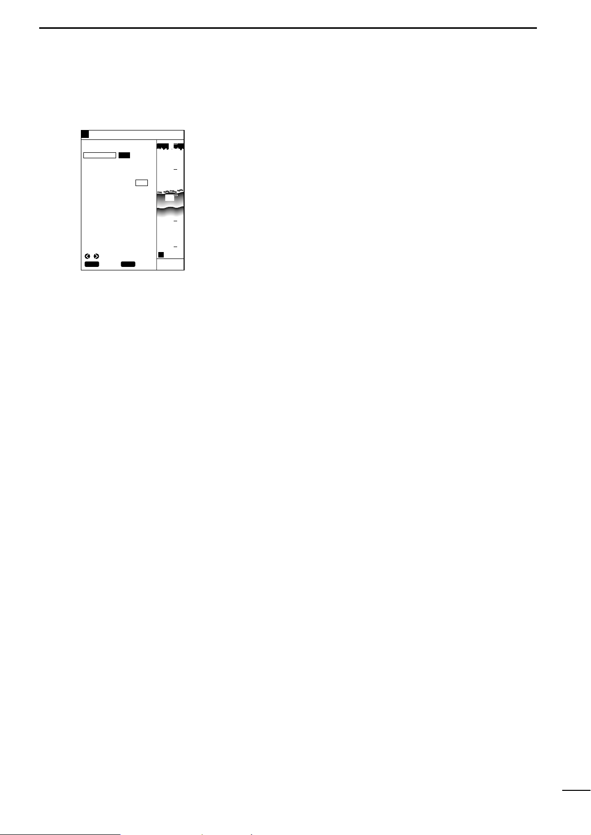
34
9
r PLOTTER MODEq POSITIONING DEVICE
(9) Selection of positioning
device
There are two options in receiving the latitude and longitude data of the current ship position.
q Press the [MENU] key.
The Main Menu screen will appear.
w Select “Positioning Menu” using the [UP] or [DOWN] key and press the [SET]
key .
The Positioning Menu screen will appear.
e Select “POS EQUIP” (positioning equipment) using the [UP] or [DO WN] k e y and
press the [SET] key.
The selected item turns blue.
r Select “GPS” or “NMEA” using the [LEFT] or [RIGHT] key.
The selected option is highlighted in yellow.
• When you select “GPS”, positioning data received by the supplied GPS receiver is used to pinpoint the current ship position.
• When you select “NMEA”, positioning data received via the e xternal NMEA input
port is used to pinpoint the current ship position.
* Selecting “NMEA” disables “DGPS” and “P ositioning Information” to be selected.
t When you finish selecting the positioning device, press the [MENU] key.
You will return to the previous screen.
GPS NMEA
GOTOCURSOR
LAT N0.000
LON E0.000
1 OFF
POSITIONING MENU
POS EQUIP
POS CORR
AVERAGING
DGPS#
POSITIONING INFO#
80.0FT
GPS34゚18.000N135゚01.000E
5
CLR
SET
SET
CANC
SEL
H
0
10
20
30
40
Page 38

35
10
r PLOTTER MODEq CORRECTION OF SHIP POSITIONING ERROR
(10)-1 Correcting a ship
positioning error
(10)-2 Correction using the
cross hair cursor
(10)-3 Correction with
latitude/longitude entry
If the current ship position on screen differs from that on the nautical chart
in latitude and/or longitude, you can correct such a ship positioning error
with ease.
There are two ways for positioning error correction: one using the cross hair cursor
and the other with latitude/longitude entry.
q On the coastline screen, press the [UP]/[DOWN] or [LEFT]/[RIGHT] key to acti-
vate the cross hair cursor.
w On the coastline screen, use the [UP]/[DOWN] or [LEFT]/[RIGHT] key to move
the cross hair cursor until its centerline coincides with the correct ship position.
e Press the [MENU] key.
The Main Menu screen will appear.
r Select “Positioning Menu” using the [UP] or [DOWN] key and press the [SET]
key .
The Positioning Menu screen will appear.
t Select “POS CORR” (Position Correction) using the [UP] or [DOWN] key and
press the [SET] key.
“GOTOCURSOR” (Goto Cursor Position) is highlighted in yellow.
y Press the [SET] key.
The latitude/longitude readings of the system will be corrected so that they correspond to the current cursor position.
u When you finish correction, press the [MENU] key.
You will return to the previous screen.
In this way of correction, the latitude/longitude of the current ship position
can be corrected by up to 9.999 minutes in 0.001-minute increments.
Orientation in latitude or longitude can also be changed from N (North) to S (South)
or E (East) to W (West), and vice versa.
q Press the [MENU] key.
The Main Menu screen will appear.
w Select “Positioning Menu” using the [UP] or [DOWN] key and press the [SET]
key .
The Positioning Menu will appear.
e Select “POS CORR” (Position Correction) using the [UP] or [DOWN] key and
press the [SET] key.
“GOTOCURSOR” (Goto Cursor Position) is highlighted in yellow.
* When you want to change the longitude, proceed with step u.
r Select “LAT” (Latitude) using the [UP] or [DOWN] key and press the [SET] key.
t Move to the latitude setting field using the [LEFT] or [RIGHT] key.
This field will be highlighted in yellow.
y Set orientation to N or S and enter the desired correction value in the field using
the [UP] or [DOWN] key; then press the [SET] key.
u Select “LON” (Longitude) using the [UP] or [DOWN] key and press the [SET]
key .
i Move to the longitude setting field using the [LEFT] or [RIGHT] key.
This field will be highlighted in yellow.
o Set orientation to E or W and enter the desired correction value in the field using
the [UP] or [DOWN] key; then press the [SET] key.
The current ship position will be corrected
!0 When you finish correction, press the [MENU] key.
You will return to the previous screen.
GPS NMEA
GOTOCURSOR
LAT N0.000
LON E0.000
1 OFF
POSITIONING MENU
POS EQUIP
POS CORR
AVERAGING
DGPS#
POSITIONING INFO#
80.0FT
GPS34゚18.000N135゚01.000E
5
CLR
SET
SET
CANC
H
0
10
20
30
40
ADJ SEL
GPS NMEA
GOTOCURSOR
LAT N0.001
LON E0.000
1 OFF
POSITIONING MENU
POS EQUIP
POS CORR
AVERAGING
DGPS#
POSITIONING INFO#
80.0FT
GPS34゚18.000N135゚01.000E
5
CLR
SET
SET
CANC
H
0
10
20
30
40
ADJ SEL
Page 39

36
11
r PLOTTER MODEq AVERAGING
(11) Averaging
Averaging is the process of averaging positioning data received by the supplied GPS receiver for past several seconds so as to minimize meandering of
the plotted track.
This process makes the track smoother, but deteriorates the response of the
screen image to changes in ship speed and azimuth.
To activate the averaging function, proceed as follows.
q Press the [MENU] key.
The Main Menu screen will appear.
w Select “Positioning Menu” using the [UP] or [DOWN] key and press the [SET]
key .
The Positioning Menu screen will appear.
e Select “Averaging” using the [UP] or [DOWN] key and press the [SET] key.
The selected item turns blue.
r Move to the averaging level field.
This field will be highlighted in yellow.
t Enter a value into the averaging level field using the [UP] or [DOWN] key and
press the [SET] key.
* A higher averaging level results in smaller meandering of the track.
y When you finish setting an averaging level, press the [MENU] key.
You will return to the previous screen.
GPS NMEA
GOTOCURSOR
LAT N0.000
LON E0.000
1 OFF
POSITIONING MENU
POS EQUIP
POS CORR
AVERAGING
DGPS#
POSITIONING INFO#
80.0FT
GPS34゚18.000N135゚01.000E
5
CLR
SET
SET
CANC
H
0
10
20
30
40
ADJ SEL
Page 40

37
12
r PLOTTER MODEq DGPS
The DGPS is a newly established system intended to impro ve the positioning
precision of the GPS. (Optional RD-200 is needed to use the DGPS).
This chapter describes how to correct the positioning data using DGPS data, select
the beacon station, and set the baud rate.
Using the DGPS data allows correction of the positioning data received by
the supplied GPS receiver.
q Press the [MENU] key.
The Main Menu screen will appear.
w Select “Positioning Menu” using the [UP] or [DOWN] key and press the [SET]
key .
The Positioning Menu screen will appear.
e Select “DGPS” using the [UP] or [DOWN] key and press the [SET] key.
The DGPS screen will appear.
r Select “Using DGPS” using the [UP] or [DOWN] key and press the [SET] key.
The selected item turns blue.
t Select “ON” using the [LEFT] or [RIGHT] key and press the [SET] key.
The selection is now saved.
y When you finish setting, press the [MENU] key.
You will return to the previous screen.
To set the beacon station, proceed as follows.
q Press the [MENU] key.
The Main Menu screen will appear.
w Select “Positioning Menu” using the [UP] or [DOWN] key and press the [SET]
key .
The Positioning Menu screen will appear.
e Select “DGPS” using the [UP] or [DOWN] key and press the [SET] key.
The DGPS screen will appear.
r Select “Beacon Frequency” using the [UP] or [DOWN] key and press the [SET]
key .
The selected item turns blue.
t Select the frequency field or “Auto”.
When you select the frequency field, proceed with step y.
When you select “Auto”, press the [SET] key.
When “Auto” is selected, a beacon station having the highest signal intensity is
automatically selected. If the system fails to synchronize with this beacon station for one minute, it automatically selects a beacon station having the second
highest signal intensity.
y Set the frequency using the [UP] or [DOWN] key and press the [SET] key.
* Set the frequency of the beacon station nearest to the current ship position.
u When you finish setting the beacon station, press the [MENU] key.
You will return to the previous screen.
(12)-1 DGPS
(12)-2 Using the DGPS
(12)-3 Setting the beacon
station
DGPS
USING DGPS
ON OFF
BEACON FREQUENCY
283.5kHz AUTO
BEACON BAUD RATE
100 200
80.0FT
GPS34゚18.000N135゚01.000E
5
CLR
SET
SET
CANC
SEL
H
0
10
20
30
40
DGPS
USING DGPS
ON OFF
BEACON FREQUENCY
283.5kHz AUTO
BEACON BAUD RATE
100 200
80.0FT
GPS34゚18.000N135゚01.000E
5
CLR
SET
SET
CANC
H
0
10
20
30
40
ADJ SEL
Page 41

38
14
r PLOTTER MODEq DOP AS A POSITIONING PRECISION INDICATOR
To set the baud rate (transmission speed) of the beacon station, proceed as
follows.
q Press the [MENU] key.
The Main Menu screen will appear.
w Select “Positioning Menu” using the [UP] or [DOWN] key and press the [SET]
key .
The Positioning Menu screen will appear.
e Select “DGPS” using the [UP] or [DOWN] key and press the [SET] key.
The DGPS screen will appear.
r Select “Beacon Baud Rate” using the [UP] or [DOWN] key and press the [SET]
key .
The selected item turns blue.
t Select “100” or “200” using the [LEFT] or [RIGHT] key and press the [SET] key.
The baud rate of the beacon station will be set as you selected.
y When you finish setting the baud rate, press the [MENU] key.
You will return to the previous screen.
* If the frequency of the beacon station has been set to “Auto” in section (12)-3,
the baud rate of the beacon station is also set automatically.
In this case, manual baud rate setting is ignored.
To access the Positioning Information screen where information on the
DGPS/GPS in use is displayed, proceed as follows.
q Press the [MENU] key.
The Main Menu screen will appear.
w Select “Positioning Menu” using the [UP] or [DOWN] key and press the [SET]
key .
The Positioning Menu screen will appear.
e Select “Positioning Info” using the [UP] or [DOWN] key and press the [SET] key.
The Positioning Information screen will appear.
r Press the [MENU] key to return to the previous screen.
The DOP (Dilution Of Precision) is a positioning precision indicator which
represents the geometrical arrangement of the navigational satellites and the
ship.
The DOP ranges from “0.00” (best arrangement) to “99.99” (worst arrangement).
Note that the positioning error of the GPS may increase depending on policies of
the U.S. Department of Defense.
(12)-4 Setting the baud rate of
the beacon station
(13) Access to Positioning
Information screen
(14) DOP as a Positioning
Precision Indicator
80.0FT
GPS34゚18.000N135゚01.000E
5
CLR
BACK
H
0
10
20
30
40
POSITIONING INFO
SAT# S/N BRG ELV
DOP
1.50
DGPS INFOMATION
RD-200
Rev.1.1
FREQUENCY 283.5
kHz
BAUD RATE 200
S/N 00
12 50 0 81
15 45 90 79
02 40 180 56
16 52 270 63
20 60 45 30
22 30 135 10
10 56 225 25
09 63 315 44
Bad geometrical arrangement: DOP is large.
Good geometrical arrangement: DOP is small.
DGPS
80.0FT
GPS34゚18.000N135゚01.000E
5
CLR
SET
SET
CANC
H
0
10
20
30
40
USING DGPS
ON OFF
BEACON FREQUENCY
283.5kHz AUTO
BEACON BAUD RATE
100 200
SEL
Page 42

39
15
r PLOTTER MODEq ALARM FUNCTION
(15)-1 A vailable alarms
As shown in the table below, there are three types of plotter-related alarms.
The alarm zone can be set to a maximum of 9.99 NM (or 9.99 km or 9.99 Ml)
around the ship position in increments of 0.01 NM (or 0.01 km or 0.01 Ml).
The alarm zone are displayed in the unit specified on the Unit setting screen (☞
P. 63).
Alarm zone
Beeps
Beeps
Alarm zone
Alarm zone
Beeps
Current ship position
or turning point
Current ship position
or turning point
Previous turning point
Turning point or destination
Turning point or destination
Current ship position or turning point
Turning point or destination
|Out-of-destination alarm
|Arrival alarm
|Out-of-course alarm
After the ship arrived at the destination, an alarm
zone is established between the current destination
and the next turning point or the next destination.
When the ship enters the alarm zone around
the destination, an arrival alarm is displayed and
beeps are produced.
When the ship leaves the alarm zone around
the destination, a range alarm is displayed and
beeps are produced.
When the ship deviates from the alarm zone
during navigation, a range alarm is displayed
and beeps are produced.
When the ship enters the alarm zone around
the destination, an arrival alarm is displayed and
beeps are produced.
Beeps
Alarm type
Arrival alarm
Out-of-destination alarm
Out-of-course alarm
Description
When the ship enters the alarm zone around the
destination, beeps are produced and an ARRV
alarm is displayed on the screen.
When the ship leaves the alarm zone around the
destination, beeps are produced and a ZONE
alarm is displayed on the screen.
When the ship deviates from the alarm zone during
navigation, beeps are produced and a ZONE alarm
is displayed on the screen. When the ship returns
within the alarm zone, beeps stop. When the ship
deviates from the alarm zone again, beeps are
produced.
Page 43

40
15
r PLOTTER MODEq ALARM FUNCTION
(15)-2 Setting the alarm zone
To set the alarm zone, proceed as follows.
Perform steps q to e when simply turning on or off the alarm function.
q Press the [MENU] key.
The Main Menu screen will appear.
w Select “Alarm Menu” using the [UP] or [DOWN] key and press the [SET] key.
The Alarm Menu screen will appear.
e Select “Alarm Zone” using the [UP] or [DOWN] key and press the [SET] key.
The selected item turns blue.
* To cancel the alarm function, select “OFF” and press the [SET] key.
r Move to the alarm zone setting field using the [LEFT] or [RIGHT] key.
This field will be highlighted in yellow.
t Set a value into the alarm zone setting field using the [UP] or [DOWN] key and
press the [SET] key.
The setting will be saved.
y When you finish setting the alarm zone, press the [MENU] key.
You will return to the previous screen.
* To stop beep sounds temporarily, press the [CLR] key.
DEPTH 1FT OFF
SHALLOW 1FT OFF
FISH DEPTH 1FT OFF
WIDTH 1FT
ALARM ZONE 0.01NM OFF
ALARM MENU
80.0FT
GPS34゚18.000N135゚01.000E
5
CLR
SET
SET
CANC
H
0
10
20
30
40
ADJ SEL
Page 44

41
Page 45

42
4
rSOUNDER MODEq TABLE OF CONTENTS
!!!!!!!!!!!!!!!!!!!!!!!!!!!!!!!!!!!!!!!!!!!!!!!!!!
SOUNDER MODE
!!!!!!!!!!!!!!!!!!!!!!!!!!!!!!!!!!!!!!!!!!!!!!!!!!
(1) AVAILABLE SCREENS AND INDICATIONS . . . . . . . . . . . . . . . . . . . . . . . . . . . . . . . . . . . . . . . . . . . . . . . . . . . . . . .44
(1)-1 How to access screens . . . . . . . . . . . . . . . . . . . . . . . . . . . . . . . . . . . . . . . . . . . . . . . . . . . . . . . . . . . . . . . . . . . . . . 44
(1)-2 Standard screen . . . . . . . . . . . . . . . . . . . . . . . . . . . . . . . . . . . . . . . . . . . . . . . . . . . . . . . . . . . . . . . . . . . . . . . . . . . 45
(1)-3 Standard + A scope screen . . . . . . . . . . . . . . . . . . . . . . . . . . . . . . . . . . . . . . . . . . . . . . . . . . . . . . . . . . . . . . . . . . 47
(1)-4 Dual screen . . . . . . . . . . . . . . . . . . . . . . . . . . . . . . . . . . . . . . . . . . . . . . . . . . . . . . . . . . . . . . . . . . . . . . . . . . . . . . 47
(1)-5 Standard + Bottom lock screen . . . . . . . . . . . . . . . . . . . . . . . . . . . . . . . . . . . . . . . . . . . . . . . . . . . . . . . . . . . . . . . 48
(1)-6 Standard + Marker zoom-in screen . . . . . . . . . . . . . . . . . . . . . . . . . . . . . . . . . . . . . . . . . . . . . . . . . . . . . . . . . . . . 48
(2) SELECTION OF FREQUENCY . . . . . . . . . . . . . . . . . . . . . . . . . . . . . . . . . . . . . . . . . . . . . . . . . . . . . . . . . . . . . . . . . 49
(3) SETTING OF IMMUNITY TO AIR BUBBLES . . . . . . . . . . . . . . . . . . . . . . . . . . . . . . . . . . . . . . . . . . . . . . . . . . . . . . 49
(4) SETTING OF DISPLAY SPEED . . . . . . . . . . . . . . . . . . . . . . . . . . . . . . . . . . . . . . . . . . . . . . . . . . . . . . . . . . . . . . . . 50
(5) SETTING OF BACKGROUND COLOR . . . . . . . . . . . . . . . . . . . . . . . . . . . . . . . . . . . . . . . . . . . . . . . . . . . . . . . . . . 50
(6) SETTING OF INTERFERENCE REJECTION . . . . . . . . . . . . . . . . . . . . . . . . . . . . . . . . . . . . . . . . . . . . . . . . . . . . . . 51
(7) SETTING OF NOISE REDUCTION . . . . . . . . . . . . . . . . . . . . . . . . . . . . . . . . . . . . . . . . . . . . . . . . . . . . . . . . . . . . . . 51
(8) MANUAL SETTING OF SENSITIVITY . . . . . . . . . . . . . . . . . . . . . . . . . . . . . . . . . . . . . . . . . . . . . . . . . . . . . . . . . . . . 52
(9) MANUAL SETTING OF DEPTH RANGE . . . . . . . . . . . . . . . . . . . . . . . . . . . . . . . . . . . . . . . . . . . . . . . . . . . . . . . . . . 52
(10) SETTING OF DEPTH SHIFT . . . . . . . . . . . . . . . . . . . . . . . . . . . . . . . . . . . . . . . . . . . . . . . . . . . . . . . . . . . . . . . . . . . 53
(11) SELECTION OF AUTO OPERATION . . . . . . . . . . . . . . . . . . . . . . . . . . . . . . . . . . . . . . . . . . . . . . . . . . . . . . . . . . . . 53
(12) DEPTH MEASUREMENT . . . . . . . . . . . . . . . . . . . . . . . . . . . . . . . . . . . . . . . . . . . . . . . . . . . . . . . . . . . . . . . . . . . . . 54
(13) SETTING OF ZOOM-IN RANGE ON BOTTOM LOCK SCREEN . . . . . . . . . . . . . . . . . . . . . . . . . . . . . . . . . . . . . . . . 54
(14) SETTING OF MARKER ZOOM-IN RANGE . . . . . . . . . . . . . . . . . . . . . . . . . . . . . . . . . . . . . . . . . . . . . . . . . . . . . . . . 55
(15) SETTING OF SOUNDER ALARM RANGES . . . . . . . . . . . . . . . . . . . . . . . . . . . . . . . . . . . . . . . . . . . . . . . . . . . . . . . 55
(16) HOW TO READ IMAGES . . . . . . . . . . . . . . . . . . . . . . . . . . . . . . . . . . . . . . . . . . . . . . . . . . . . . . . . . . . . . . . . . . . . . 57
(16)-1 Reflections from the sea bottom . . . . . . . . . . . . . . . . . . . . . . . . . . . . . . . . . . . . . . . . . . . . . . . . . . . . . . . . . . . . . . . 57
Å Reading topographical features of the sea bottom . . . . . . . . . . . . . . . . . . . . . . . . . . . . . . . . . . . . . . . . . . . . . . . . 57
ı Reading geological features of the sea bottom . . . . . . . . . . . . . . . . . . . . . . . . . . . . . . . . . . . . . . . . . . . . . . . . . . 57
(16)-2 Reflection from a shoal of fish . . . . . . . . . . . . . . . . . . . . . . . . . . . . . . . . . . . . . . . . . . . . . . . . . . . . . . . . . . . . . . . . 58
Å Reading the size of a shoal of fish . . . . . . . . . . . . . . . . . . . . . . . . . . . . . . . . . . . . . . . . . . . . . . . . . . . . . . . . . . . . 58
ı Reading the density of a shoal of fish . . . . . . . . . . . . . . . . . . . . . . . . . . . . . . . . . . . . . . . . . . . . . . . . . . . . . . . . . . 58
(16)-3 Secondary reflections from the sea bottom . . . . . . . . . . . . . . . . . . . . . . . . . . . . . . . . . . . . . . . . . . . . . . . . . . . . . . 59
(16)-4 Plankton layers or tidal current layer . . . . . . . . . . . . . . . . . . . . . . . . . . . . . . . . . . . . . . . . . . . . . . . . . . . . . . . . . . . . 59
Å Plankton layers . . . . . . . . . . . . . . . . . . . . . . . . . . . . . . . . . . . . . . . . . . . . . . . . . . . . . . . . . . . . . . . . . . . . . . . . . . . 59
ı Tidal current layers . . . . . . . . . . . . . . . . . . . . . . . . . . . . . . . . . . . . . . . . . . . . . . . . . . . . . . . . . . . . . . . . . . . . . . . . 59
(16)-5 Thermoclines . . . . . . . . . . . . . . . . . . . . . . . . . . . . . . . . . . . . . . . . . . . . . . . . . . . . . . . . . . . . . . . . . . . . . . . . . . . . . 60
(16)-6 Influence of air bubbles . . . . . . . . . . . . . . . . . . . . . . . . . . . . . . . . . . . . . . . . . . . . . . . . . . . . . . . . . . . . . . . . . . . . . . 60
(16)-7 Phantom images . . . . . . . . . . . . . . . . . . . . . . . . . . . . . . . . . . . . . . . . . . . . . . . . . . . . . . . . . . . . . . . . . . . . . . . . . . . 60
Page 46

43
Page 47

44
1
rSOUNDER MODEq AVAILABLE SCREENS AND INDICATIONS
In fishfinder mode, the following five screens are available.
Pressing the [SOUNDER] key once in plotter mode allows you to select from
among the standard screen, standard + A scope screen, dual screen, standard +
bottom lock screen, and standard + Marker zoom-in screen in this order.
* If no water temperature sensor is installed, the water temperature field is blank.
(1)-1 How to access screens
Screen name
Standard screen
Indication Screen name Indication
This screen shows an
image of underwater
that is detected at either
of a high (H) or low (L)
frequency.
Standard + A scope screen
This screen consists of
the standard screen and
its zoom-in screen.
Dual screen
This screen shows two
images of underwater
that are detected at
both of a high (H) and
low (L) frequencies.
* Frequencies set on
the Fishfinder Menu
screen are displayed
on the right.
Standard +
Maker zoom-in screen
This function provides
zoom-in display around
the variable range
marker for detailed
observation of
underwater activity such
as fish schools.
This screen consists of
the standard screen and
the bottom lock screen.
GPS 48°21.417N 125°26.643W
31.5
H
AUTO
FT
43.4
315
°T 10.
2KT 58°F
20
40
60
80
0
100
L
H
FT
43.4
315
°T 10.
2KT 58°F
GPS 48°21.417N 125°26.643W
20
40
60
80
0
100
20
40
60
80
0
100
H
2
1
3
4
5
0
3
4
2
1
5
GPS 48°21.417N 125°26.643W
19.5
FT
43.4
315
°T 10.
2KT 58°F
20
40
60
80
0
100
AUTO
H
FT
57.6
315
°T 10.
2KT 58°F
GPS 48°21.417N 125°26.643W
20
40
60
80
0
100
0
10
5
H
FT
43.4
315
°T 10.
2KT 58°F
GPS 48°21.417N 125°26.643W
20
40
60
80
0
100
Standard +
Bottom lock screen
Page 48

45
1
rSOUNDER MODEq AVAILABLE SCREENS AND INDICATIONS
(1)-1 Standard screen
This field shows the positioning device in use.
This field shows the current ship position in latitude/longitude or time difference.
In this field, a moving 30-second time mark is always indicated in yellow.
The current ship position is located at the upper right corner in fishfinder mode.
Alarm range markers are monitor range indicators. The shoal alarm range is indicated in red, the depth alarm range in yellow, and the fish alarm range in green.
This screen has FT scales in 20 FT (default; m) increments (☞ P. 52).
The depth marker (green) and depth value are indicated during depth measurement.
This field shows the current depth of water. If the level of reflections from the bottom is low, this may not be displayed.
This field shows the current water temperature ranging from 0.0 to +40.0 in °C or
+32.0 to +104 in °F. If the water temperature is out of this range, “**.*” is displayed.
If no water temperature sensor is installed, the field is blank.
GPS 48°21.417N 125°26.643W
31.5
レンジRANGE
z
x
c
v
b
n
m
,
.
⁄0⁄1
⁄2
⁄3
⁄4
⁄5
⁄6
⁄7
⁄8
DPTH
ALRM
ZONE
ALRM
H
AUTO
FT
43.4
315
°T 10.
2KT 58°F
20
40
60
80
0
100
z Positioning device
x Ship position
c Time mark
v Ship position
b Alarm range marker
n Depth scale
m Depth marker
, Depth
. Water temperature
Indication
Positioning device in use
EXT
External NMEA
DGPS
DGPS+GPS
GPS
GPS
Page 49

46
1
rSOUNDER MODEq AVAILABLE SCREENS AND INDICATIONS
⁄0 Ship speed
⁄1 Operation mode
⁄2 Bearing
⁄3 Frequency
⁄4 [RANGE] key
⁄5 Sensitivity level bar
⁄6 Color pattern
⁄7 Plotter alarm indication
⁄8 Fishfinder alarm
This field shows the current ship speed.
When the system operates in auto mode (☞ P.53), “AUTO” is indicated in this field.
This field shows the current bearing of the bow (at which the ship is navigated).
•T (TRUE); True bearing, M (MAG); Magnetic bearing (p. 66)
This field shows the frequency in use (Ó: high frequency, Ò: low frequency).
In the dual screen, the frequency specified on the Fishfinder Menu screen is displayed on the right.
This field shows the current setting (Range/Shift/Auto) of the range key.
The level bar indicates the sensitivity in 32 levels.
When the Sensitivity key is pressed to adjust the sensitivity level, the level bar
appears on the screen while highlighted in yellow.
The color pattern consists of eight colors arranged in descending order of reflec-
tion level. If the noise reduction function (☞ P. 51) is ON, however, colors having a
lower reflection level may not be displayed.
The background color can be set to “Blue” or “Black” (☞ P. 50). The image sensi-
tivity should be adjusted so that the portion close to the sea bottom is indicated in
red. If this portion has a yellow-green color, the depth or the shape of sea bottom
may not be detected due to weak reflection from the sea bottom.
Alarms indicated in this field include range alarm and arrival alarm.
Alarms indicated in this field include depth alarm, fish alar m and shoal alarm.
Red
[
Reflection strong Reflection weak
\
\[
Detection is enabled Detection is disabled
Orange Yellow
Yellow-
green
Green Light blue
Dark blue
(Black)
Blue
Page 50

47
1
rSOUNDER MODEq AVAILABLE SCREENS AND INDICATIONS
L
H
FT
43.4
315
°T 10.
2KT 58°F
GPS 48°21.417N 125°26.643W
Low frequency image High frequency image
(frequency specified
on the Sounder
Menu screen)
20
40
60
80
0
100
20
40
60
80
0
100
(1)-4 Dual screen
The dual screen consists of high and low frequency images of the same contents
as the standard screen.
The frequency specified on the Sounder Menu screen is indicated on the right.
AUTO
H
FT
57.6
315
°T 10.
2KT 58°F
z
x
c
v
b
GPS 48°21.417N 125°26.643W
20
40
60
80
0
100
(1)-3 Standard + A scope screen
The A scope image represents reflections from the sea bottom or a shoal of fish in
amplitude and color.
For common indications on different screens, such as alarm range
marker, time mark and sensitivity
level, see section (1)-2 “Standard
screen”.
Indicated in red due to large amplitude
No change in color (background color) due to nothing detected
Small amplitude
Indicated in red due to large amplitude
Indicated in red due to large amplitude
z Strong reflection
(oscillation line)
x No reflection
c Weak reflection (from fish)
v Strong reflection
(from sea bottom)
b Strong reflection
(secondary reflection)
For common indications on different screens, such as alarm range
marker, time mark and sensitivity
level, see section (1)-2 “Standard
screen”.
Page 51

48
1
rSOUNDER MODEq AVAILABLE SCREENS AND INDICATIONS
(1)-6 Standard + Marker zoom-in screen
Underwater area around this marker is zoomed in.
This image covers the specified underwater area (☞ P. 55).
This line represents the center of the marker zoom-in image and corresponds to
the depth marker on the standard image.
H
2
1
3
4
5
0
3
4
2
1
5
GPS 48°21.417N 125°26.643W
x
z
c
19.5
FT
43.4
315
°T 10.
2KT 58°F
20
40
60
80
0
100
z Depth marker
x Maker zoom-in image
c Zoom-in centerline
This image is the same as that on the standard screen.
This image covers the specified bottom area (☞ P. 54).
z Standard image
x Bottom lock image
(1)-5 Standard + Bottom lock screen
0
10
5
H
FT
57.6
315
°T 10.
2KT 58°F
GPS 48°21.417N 125°26.643W
z
x
20
40
60
80
0
100
For common indications on different screens, such as alarm range
marker, time mark and sensitivity
level, see section (1)-2 “Standard
screen”.
For common indications on different screens, such as alarm range
marker, time mark and sensitivity
level, see section (1)-2 “Standard
screen”.
Page 52

49
2
rSOUNDER MODEq SELECTION OF FREQUENCY
(2) Selection of Frequency
(3) STC; Setting of Immunity
to Air Bubbles
To select the Sounder frequency between “High (H)” and “Low (L)”, proceed
as follows. (Default; H)
q Press the [MENU] key.
The Main Menu screen will appear.
w Select “Sounder Menu” using the [UP] or [DOWN] key and press the [SET] key.
The Sounder Menu screen will appear.
e Select “Frequency” using the [UP] or [DOWN] key and press the [SET] key.
The selected item turns blue.
r Select “Ò” (50 kHz) or “Ó” (200 kHz)using the [LEFT] or [RIGHT] key and press
the [SET] key.
The selected frequency will be indicated in the frequency field on fishfinder
screens.
t When you finish selecting the frequency, press the [MENU] key to close the Main
Menu screen.
The following table summarizes characteristics and main applications of the low
and high frequencies.
To set the immunity to air bubbles in the sea surfaces so as to improve the
image legibility, proceed as follows. (Default; 1)
q Press the [MENU] key.
The Main Menu screen will appear.
w Select “Sounder Menu” using the [UP] or [DOWN] key and press the [SET] key.
The Sounder Menu screen will appear.
e Select STC using the [UP] or [DOWN] key and press the [SET] key.
The selected item turns blue.
r Enter the desired immunity lev el from among 15 le vels using the [UP] or [DO WN]
key and press the [SET] key.
The setting is now saved.
t When you finish setting the immunity level, press the [MENU] key to close the
Main Menu screen.
SOUNDER MENU
DSP SPEED
STC
FT
43.4
I.R
N.R
L
H
1
OFF
OFF
5
STOP
ON
1
CLR
SET
SET
CANC
SEL
FREQUENCY
GPS 48°21.417N 125°26.643W
20
40
60
80
0
100
SOUNDER MENU
DSP SPEED
STC
FT
43.4
I.R
N.R
L
H
1
OFF
OFF
5
STOP
ON
1
CLR
SET
SET
CANC
ADJ
SEL
FREQUENCY
GPS 48°21.417N 125°26.643W
20
40
60
80
0
100
Immunity level too low
H
Immunity level too high
H
FT
43.4
315
°T 10.
2KT 58°F
GPS 48°21.417N 125°26.643W
20
40
60
80
0
100
20
40
60
80
0
100
GPS 48°21.417N 125°26.643W
FT
43.4
315
°T 10.
2KT 58°F
Frequency
Directivity
(directional angle)
Depth coverage
Resolution
(detection of fish density)
Immunity to bubbles and
underwater noises
Main application
Low (L)
High (large)
Deep
Low
Low
Search of board
area, underwater
geological survey
High (H)
Low (small)
Shallow
High
High
Diagnosis of fish
density or fish size
Page 53

50
4
rSOUNDER MODEq SETTING OF DISPLAY SPEED
(4) Setting of Display speed
(5) Selection of background
color
The display speed can be adjusted to “1” thru “5” or “STOP”. (Default; 5)
Selecting a high display speed enlarges the image horizontally and will thus be
helpful for analyzing the image.
If you want to do detection for a long time, you should select a low display speed.
To set the display speed, proceed as follows.
q Press the [MENU] key.
The Main Menu screen will appear.
w Select “Sounder Menu” using the [UP] or [DOWN] key and press the [SET] key.
The Sounder Menu screen will appear.
e Select “DSP speed” using the [UP] or [DOWN] key and press the [SET] key.
The selected item turns blue.
r Move to the display speed setting field or “STOP” using the [LEFT] or [RIGHT]
key .
* When moving to the speed setting field, proceed with step t.
* When selecting “STOP”, press the [SET] key.
The DSP speed is STOP.
t Select the desired value (“1” to “5”) using [UP] or [DOWN] key and press the
[SET] key.
The selection is now saved
y When you finish setting the display speed, press the [MENU] key to close the
Main Menu screen.
SOUNDER MENU
DSP SPEED
STC
FT
43.4
I.R
N.R
L
H
1
OFF
OFF
5
STOP
ON
1
CLR
SET
SET
CANC
ADJ
SEL
FREQUENCY
GPS 48°21.417N 125°26.643W
20
40
60
80
0
100
Rate indication
Rate
STOP
—
1 ~ 5
Low ba High
DISP MODE
BKG COLOR
LAND
SEA
NAME
D CON≦ 5m
D CON=10m
D CON≧20m
LIGHT
GRID
DISP MAPS
SCREEN SETTING
1
2
BLUE
YELL CSLN
BLUE
WHIT OFF
LBLU OFF
LBLU OFF
LBLU OFF
RED OFF
BLUE OFF
WHIT OFF
GPS34゚18.000N135゚01.000E
5
CLR
SET
SET
CANC
SEL
FT
43.4
The background color can be set to “Blue” or “Black”. (Default; BLUE)
Select a background color according to the ambient working conditions as follows.
q Press the [MENU] key.
The Main Menu screen will appear.
w Select “Screen Setting” using the [UP] or [DOWN] key and press the [SET] key.
The Screen Setting screen will appear.
e Select “BKG COLOR” (Background color) using the [UP] or [DOWN] key and
press the [SET] key.
The selected item turns blue.
r Select “BLUE” or “BLK” (Black) using the [UP] or [DOWN] key and press the
[SET] key.
Background is displayed in the selected color.
t When you finish setting the color of background, press the [MENU] key to close
the Main Menu screen.
Page 54

51
6
rSOUNDER MODEq SETTING OF INTERFERENCE REJECTION
(6) Setting of Interference
Rejection
The system has an interference rejection function that removes inductive
interference derived by a generator on the ship or noise disturbance caused
by a fishfinder of other ships. (Default; ON)
To activate the interference rejection function, proceed as follow.
q Press the [MENU] key.
The Main Menu screen will appear.
w Select “Sounder Menu” using the [UP] or [DOWN] key and press the [SET] key.
The Sounder Menu screen will appear.
e Select “I.R” using the [UP] or [DOWN] key and press the [SET] key.
The selected item turns blue.
r Select “ON” using the [LEFT] or [RIGHT] key and press the [SET] key.
The setting is now saved.
t When you finish setting, press the [MENU] key to close the Main Menu screen.
SOUNDER MENU
DSP SPEED
STC
FT
43.4
I.R
N.R
L
H
1
OFF
OFF
5
STOP
ON
1
CLR SET
SEL
SETCANC
FREQUENCY
GPS 48°21.417N 125°26.643W
20
40
60
80
0
100
The system has an noise reduction function that suppresses noises caused
by contamination of seawater or other sources. These noises ma y appear as
blue or green dots on fishfinder screens. (Default; OFF)
To suppress the noises and make the image legible, proceed as follows.
q Press the [MENU] key.
The Main Menu screen will appear.
w Select “Sounder Menu” using the [UP] or [DOWN] key and press the [SET] key.
The Sounder Menu screen will appear.
e Select “N.R” using the [UP] or [DOWN] key and press the [SET] key.
The selected item turns blue.
r Move to the noise reduction level by using the [LEFT] or [RIGHT] key.
t Select the desired level (“1” to “4”) using the [UP] or [DOWN] key and press the
[SET] key.
The selection is now saved.
*Level “1” minimizes noise suppression and Level “4” maximizes it.
* If you select “OFF”, the noise reduction function is not used.
y When you finish setting, press the [MENU] key to close the Main Menu screen.
(7) Setting of Noise Reduction
Noise disturbance caused
by other fishfinder
Inductive interference caused
by a generator on the ship Anti-interference ON
H
4
H
H
FT
43.5
315°゜10.2KT 58°F
FT
43.5
FT
43.5
315°゜10.2KT 58°F
315°
゜10.
2KT 58°F
GPS 48°21.417N 125°26.643W
20
40
60
80
0
100
20
40
60
80
0
100
20
40
60
80
0
100
GPS 48°21.417N 125°26.643W
GPS 48°21.417N 125°26.643W
SOUNDER MENU
DSP SPEED
STC
FT
43.4
FREQUENCY
I.R
N.R
L
H
1
OFF
OFF
5
STOP
ON
1
CLR
SET
SET
CANC
ADJ
SEL
GPS 48°21.417N 125°26.643W
20
40
60
80
0
100
Page 55

52
8
rSOUNDER MODEq MANUAL SETTING OF SENSITIVITY
(8) Manual Setting of
Sensitivity
To set the sensitivity to ultrasonic reflected from the sea bottom, proceed as
follows.
q Press the [GAIN] key.
The level bar will appear on the screen and is indicating the current level.
* The level bar is inoperative when the system is in auto sensitivity mode or auto
operation mode.
w Using the [UP] or [DOWN] key, set the sensitivity level so that the portion close
to the sea bottom is displayed in red (color shown at the top of the color pattern)
and noises (blue) are not found in the water.
Each time you press the [UP] or [DOWN] key, the level bar changes in height in
increments of one step.
ePress the [GAIN] or [SET] key to save the setting.
The sensitivity setting is critical to ensure optimal fishfinder performance.
Be sure to set the sensitivity properly when using the system in manual
mode.
The depth range is an underwater range in depth that contained in the screen
image.
Available units of the depth range include m (metes), FT (feet) and FM (fathoms)
(☞ P. 63).
To set the depth range manually, proceed as follows.
q Press the [RANGE] key.
“RANGE” (“SHIFT” or “AUTO”) will be indicated in the depth field on the screen.
* If auto operation is active, it is canceled.
w Select “RANGE” using the [LEFT] or [RIGHT] key.
e Select the desired depth range using the [UP] or [DOWN] key.
Each time you press the [UP] or [DOWN] key, the depth range changes in increments of one step.
* On the Depth Range Selection screen (☞ P. 67), you can preset up to 31 depth
ranges suited to the sea bottom.
r Press the [RANGE] or [SET] key to save the setting.
(9) Manual Setting of Depth
Range
H
FT
43.4
Sensitivity level bar
CLR
SET
SET
CANC
ADJ
GPS 48°21.417N 125°26.643W
20
40
60
80
0
100
Sensitivity level too high
Sensitivity level too low
H
FT
43.4
315°T 10.2KT 58°F
H
315°T 10.2KT 58°F
FT
43.4
20
40
60
80
0
100
20
40
60
80
0
100
GPS 48°21.417N 125°26.643W GPS 48°21.417N 125°26.643W
H
FT
43.5
Depth field
RANGE
CLR
SET
SET
CANC
SEL
ADJ
GPS 48°21.417N 125°26.643W
20
40
60
80
0
100
Depth range (default)
Units of depth
m (meters)
FT (feet)
FM (fathoms)
0 ~ 5
0 ~ 20
0 ~ 3
0 ~ 10
0 ~ 40
0 ~ 5
0 ~ 20
0 ~ 60
0 ~ 10
0 ~ 40
0 ~ 100
0 ~ 20
0 ~ 80
0 ~ 180
0 ~ 40
* The depth ranges default to (are factory set to) those shown in the table above.
0 ~ 160
0 ~ 260
0 ~ 80
0 ~ 240
0 ~ 600
0 ~ 120
0 ~ 320
0 ~ 1000
0 ~ 160
0 ~ 480
0 ~ 1500
0 ~ 260
0 ~ 640
0 ~ 2000
0 ~ 350
Page 56

53
10
rSOUNDER MODEq SETTING OF DEPTH SHIFT
(10) Setting of Depth Shift
Setting the depth shift allows you to specify a depth at which the upper edge
of the screen image stands.
To set the depth shift, proceed as follows.
q Press the [RANGE] key.
“RANGE” (“SHIFT” or “AUTO”) will be indicated in the depth field on the screen.
w Select “Shift” using the [LEFT] or [RIGHT] key.
e Select the desired depth shift using the [UP] or [DOWN] key.
Each time you press the [UP] or [DOWN] key, the depth shift changes in incre-
ments of one step.
r Press the [RANGE] or [SET] key to save the setting.
Auto operation is suitable for beginners to use the fishfinder.
Detection of the sea bottom needs subtle adjustment of the depth range according
to the shape of the sea bottom.
The use of the auto operation function of the system, however, permits the bottom
image to be always displayed on the screen.
To use auto operation, proceed as follows.
q Press the [RANGE] key.
“RANGE” (“SHIFT” or “AUTO”) will be indicated in the depth field on the screen.
w Select “AUTO” using the [LEFT] or [RIGHT] key.
e Press the [RANGE] or [SET] key to save the setting.
(11) Selection of Auto
Operation
H
Depth field
SHIFT
CLR
SET
SET
CANC
SEL
ADJ
FT
43.4
40
60
80
100
H
H
DGPS34゚18.000N135゚01.000E
When no depth shift is set
When a 20 FT depth shift is set
Image is shifted by 20 FT in depth.
315°T 10.2KT 58°F
FT
43.4
20
40
60
80
120
100
20
40
60
80
0
100
GPS 48°21.417N 125°26.643W
315°T 10.2KT 58°F
FT
43.4
H
H
Manual operation
Auto operation
AUTO
GPS 48°21.417N 125°26.643W
20
40
60
80
0
100
FT
53.4
315°T 10.2KT 58°F
GPS 48°21.417N 125°26.643W
20
40
60
80
0
100
FT
53.4
315°T 10.2KT 58°F
H
Depth field
AUTO
AUTO
CLR
SET
SET
CANC
SEL
ADJ
FT
43.4
GPS 48°21.417N 125°26.643W
20
40
60
80
0
100
Page 57

54
12
rSOUNDER MODEq
DEPTH MEASUREMENT
(12) Depth Measurement
(13) Setting of Zoom-in range
on Bottom lock Screen
The depth of the sea bottom or a shoal of fish can be measured precisely.
The depth is indicated by a green line called the depth marker and a numerical
value.
To measure the depth, proceed as follows.
q Press the [UP]/[DOWN] or [LEFT]/[RIGHT] key.
The depth marker and a depth value will appear at the top of the screen.
w Press the [UP] or [DOWN]key until the depth marker moves to the desired posi-
tion.
The depth of the position will be numerically indicated underneath the depth
marker.
* Pressing the [UP] or [DOWN] key for 0.5 second or more causes the depth
marker to move continuously.
* In Combination mode, the depth marker cannot be used.
e To exit from the depth measurement mode, select other fishfinder screens or
press the [CLR].
The zoom-in range displayed on the standard + bottom lock screen can be
selected from among four options.
On the bottom rock screen, a certain depth range measured from the sea bottom
is zoomed in.
To set the zoom-in range, proceed as follows.
q Press the Sounder key to select “Standard + Bottom lock Screen”.
w Press the [ZOOM-IN] or [ZOOM-OUT] key until the desired depth range is
reached.
e Release the [ZOOM-IN] or [ZOOM-OUT] key.
The setting is saved.
32.5
H
Depth valueDepth marker
315°T 10.2KT 58°F
FT
43.4
GPS 48°21.417N 125°26.643W
20
40
60
80
0
100
0 ~ 5
0 ~ 15
0 ~ 3
0 ~ 20
0 ~ 60
0 ~ 10
0 ~ 10
0 ~ 30
0 ~ 5
0 ~ 40
0 ~ 120
0 ~ 20
Units of depth
m (meters)
FT (feet)
FM (fathoms)
Bottom zoom-in range
Page 58

55
14
rSOUNDER MODEq SETTING OF MARKER ZOOM-IN RANGE
The zoom-in range displayed on the standard + marker zoom-in screen can
be selected from among four options.
The zoom-in function provides zoom-in display around the var iable range marker
for detailed observation of underwater activity such as fish schools.
To set the zoom-in range, proceed as follows.
q Press the Sounder key to select “Standard + Marker zoom-in Screen”.
* The depth mar ker will appear on the screen automatically.
w Pressing the [UP] or [DOWN] key, move the depth marker to the desired posi-
tion.
* In Combination mode, the maker zoom-in screen cannot be used.
e Press the [ZOOM-IN] or [ZOOM-OUT] key until the desired zoom-in range is
reached.
(14) Setting of Marker Zoom-
in Range
H
2
1
3
4
5
0
3
4
2
1
5
Depth marker
119.7
315°T 10.2KT 58°F
FT
43.4
GPS 48°21.417N 125°26.643W
20
40
60
80
0
100
Page 59

56
15
rSOUNDER MODEq SETTING OF SOUNDER ALARM RANGES
To set the sounder alarm ranges, proceed as follows.
q Press the [MENU] key.
The Main Menu screen will appear.
w Select “Alarm Menu” using the [UP] or [DOWN] key and press the [SET] key.
The Alarm Menu screen will appear.
e Select “Depth (Limit)”, “Shallo w (Limit)” or “Fish (Depth/Width)” using the [UP] or
[DOWN] key and press the [SET] key.
The selected item turns blue.
r Using the [LEFT] or [RIGHT] key, move to the depth setting field of the selected
item.
The depth setting item will be highlighted in yellow.
t Enter a depth value into the depth setting field using the [UP] or [DOWN] key
and press the [SET] key.
* When “Fish” is selected, entering a depth value into the depth setting field fol-
lowed by pressing the [SET] key will cause the width setting field to be highlighted in yellow.
y Each time you enter a value into each setting field, press the [SET] key.
The setting is saved.
u When you finish setting all the sounder alarm ranges, press the [MENU] key to
close the Main Menu screen.
* To stop an alarm sound temporarily, press the [CLR] key.
“Depth alarm” range
“Fish alarm” range
“Shallow alarm” range
H
315°T 10.2KT 58°F
FT
43.4
GPS 48°21.417N 125°26.643W
20
40
60
80
0
100
(15) Setting of Sounder Alarm
Ranges
FT
43.4
ALARM MENU
DEPTH
SHALLOW
FISH
ALARM ZONE
DEPTH
WIDTH
85FT
15FT
0.4
NM
OFF
OFF
OFF
OFF
15FT
18FT
CLR
SET
SET
CANC
SEL
ADJ
H
GPS 48°21.417N 125°26.643W
20
40
60
80
0
100
Three types of Sounder alarms are available as shown in the table below.
Alarm type
Depth alarm
Shallow alarm
Fish alarm
Description
When the ship enters an area where the depth of water
exceeds the specified limit, an alarm sound is produced and a
“DEPTH alarm” is displayed on the screen. When the ship
leaves the area, an alarm sound stops.
When the ship enters an area where the depth of water is
shallower than the specified limit, an alarm sound is produced
and a “SHALLOW alarm” is displayed on the screen. When the
ship leaves the area, an alarm sound stops.
When a fish school is detected within the specified bounds, an
alarm sound is produced and a “FISH alarm” is displayed on the
screen. When a fish school is undetectable within the specified
bounds, an alarm sound stops.
Page 60

57
16
rSOUNDER MODEq HOW TO READ IMAGES
(16)-1 Reflections from the
sea bottom
Å Reading topographical features
of the sea bottom
Reflections from the sea bottom are displayed in red provided that the sensitivity is properly set (☞ P. 52).
Screen images of the sea bottom provide you with information on the topographical and geological features of the sea bottom. Such information will help you
search for good fishing banks.
Submarine terrains may be flat or hilly, just as is the case with land.
On screen images, topographical features of the sea bottom are displayed,
as in:
On screen images, geological features of the sea bottom are displayed, as in:
Soil/sand Rock
H
315°T 10.2KT 58°F
FT
51.4
GPS 48°21.417N 125°26.643W
20
40
60
80
0
100
ı Reading geological features of
the sea bottom
H
Flat terrain Hilly terrain
H
315°T 10.2KT 58°F
FT
58.4
GPS 48°21.417N 125°26.643W
20
40
60
80
0
100
20
40
60
80
0
100
315°T 10.2KT 58°F
FT
43.4
GPS 48°21.417N 125°26.643W
Topographical feature
Flat
Hilly
Screen image
Assuming that its geological features are constant, the
displayed contour of a flat terrain has a uniform width.
The displayed contour of a hilly terrain has a long
tailing*
1
. This is because the ultrasonic sent from the
transducer has a certain beam angle and hence
reflections from a bank vary in time of their returning to
the transducer*
2
.
*1 The depth of water immediately underneath the ship
looks shallower than the actual depth.
*
2
The displayed contour of a bank tends to be narrow.
Geological feature
Hard
(e.g., rock, coral reef)
Soft
(e.g., soil, sand,
seeweed)
Screen image
Assuming that its geological features are constant, the
displayed contour of a hard terrain has a uniform width.
The contour of a soft terrain is display loses redness in
color and has a short railing*
1
. This is because soil or
sand absorbs much of the ultrasonic.
*
1
When slim constitutes the sea bottom, the low
frequency screen shows a long tailing.
Page 61

58
16
rSOUNDER MODEq HOW TO READ IMAGES
(16)-2 Reflection from a fish
school
Å Reading the size of a fish school
In general, reflections from a fish school form a light-colored downturn
between the sea level and bottom on the screen.
Information provided by the screen image of a fish school includes the size and
density of the shoal. Comparison, as a routine matter, between the screen image
and the actual fishery will permit you to read the image exactly.
The image size of s a fish school is in proportion to the actual size.
When the system detects two same-sized fish school at different depths, however,
the fish school located at a deeper position will be displayed as a smaller-sized
image on the screen. This is because the ultrasonic radiates at a cone-shaped
beam angle from the transducer and therefore the deeper the object position is, the
longer the time for which it is radiated with the beam. The relationship between the
image size and the depth of an object depends on the image feed rate and the ship
speed.
Larger fish school
Smaller fish school
H
Radiated with the
beam for a shorter time
Radiated with the
beam for a longer time
315°T 10.2KT 58°F
FT
71.4
GPS 48°21.417N 125°26.643W
20
40
60
80
0
100
The higher the density of a fish school is, the closer to red the color of the
image is (i.e., the higher the strength of signals reflected from the object is).
When two images having the same density (same signal strength) are displayed at
different depths on the same screen, however, the density of the two fish schools
are different; the deeper one is actually denser than the shallower one. This is
because the deeper the object position is, the more the pulses reflected from the
object delay.
ı Reading the density of a fish
school
Lower-density fish school
Higher-density fish school
H
Decrease of transmitted
pulse is small
Decrease of transmitted
pulse is large
315°T 10.2KT 58°F
FT
71.4
GPS 48°21.417N 125°26.643W
20
40
60
80
0
100
Page 62

59
16
rSOUNDER MODEq HOW TO READ IMAGES
(16)-3 Secondary reflections
from the sea bottom
In shallow-depth areas, phantom contours of the sea bottom may often occur
under the actual contour.
These phantom contours of the sea bottom are caused by secondary reflections
from the sea bottom (bounce of the ultrasonic wave between the sea bottom and
the water surface or the ship). This symptom tends to occur in particular when the
ship bottom is rocky or a low frequency is used. The secondary contours will
appear at depths of integral multiples of the actual depth of water.
Actual contour
of the sea bottom
Phantom contour due
to secondary reflections
H
315°T 10.2KT 58°F
FT
43.4
GPS 48°21.417N 125°26.643W
20
40
60
80
0
100
Tidal current layer
H
315°T 10.2KT 58°F
FT
43.4
GPS 48°21.417N 125°26.643W
20
40
60
80
0
100
Plankton layer
H
315°T 10.2KT 58°F
FT
43.4
GPS 48°21.417N 125°26.643W
20
40
60
80
0
100
Plankton may sometimes gather and form a layer.
Such a layer looks like a cloud on the screen and may expand to the depths. Since
plankton forms the food of many fish, detection of plankton layers will lead to an
increase in fishery.
Plankton are light-sensitive, and live in the depth in the daytime and emerge to a
shallow depth at night.
Tidal current layers may occur depending on the speed or route of tidal currents.
In areas where different tidal currents encounter, air bubbles or plankton form a
layer, which is displayed on the screen, as in:
(16)-4 Plankton layer s or tidal current layer
Å Plankton layers
ı Tidal current layers
Page 63

60
16
rSOUNDER MODEq HOW TO READ IMAGES
(16)-6 Influence of air bubbles
If the ultrasonic beam passes through air bubbles, reflections from a shoal of
fish or the sea bottom may deteriorate or be interrupted, resulting in voids
occurring on the screen image.
This symptom is apt to occur when a low frequency is used, the ship turns and
passes through its own track, or the sea is rough. Voids on the screen mean that
the ultrasonic energy is dissipated or absorbed by air bubbles.
Thermocline
H
315°T 10.2KT 58°F
FT
43.4
GPS 48°21.417N 125°26.643W
20
40
60
80
0
100
The side lobe from the transducer may cause phantom images.
These images tend to appear above the contour of the sea bottom in a hilly terrain,
or under the contour in a flat terrain.
(16)-7 Phantom images
Phantom images
H
Main lobe
Side lobe
315°T 10.2KT 58°F
FT
43.4
GPS 48°21.417N 125°26.643W
20
40
60
80
0
100
H
4
Voids due to air bubbles
315°T 10.2KT 58°F
FT
43.4
GPS 48°21.417N 125°26.643W
20
40
60
80
0
100
Thermocline is a lay of a body of water at which the rate of temperature
decreases with depth is at a maximum, and is displayed as a screen image.
As a thermocline reflects ultrasonic waves, it appears as a very thin line between
the sea level and bottom on the screen.
(16)-5 Thermoclines
Page 64

61
(1)
rCOMBINATION MODEq AVAILABLE SCREENS AND INDICATIONS
!!!!!!!!!!!!!!!!!!!!!!!!!!!!!!!!!!!!!!!!!!!!!!!!!!
COMBINATION MODE
!!!!!!!!!!!!!!!!!!!!!!!!!!!!!!!!!!!!!!!!!!!!!!!!!!
(1) Availab le Screens and
Indications
The coastline screen and the fishfinder screen are displayed simultaneously
in combination mode.
Screen indications and operation procedures in this mode are the same as those
in other modes, except described below on this page.
In combination mode, you cannot select other screens than shown above
nor use the depth marker.
z
x
z Coastline screen
x Sounder screen
In combination mode, the coastline screen is always displayed here.
In combination mode, the standard screen is always displayed here.
8
GPS 48°21.417N 125°26.643W
RANGE 32
FT
43.4
0°
T 10.
2KT 58°F
1
0
2
TO WP 1
4.6NM 320°
H
0
20
40
60
80
100
Page 65

62
5
INITIAL SETTING AFTER INSTALLATION
5-1 Initial setting on the SET MODE screen
The SET MODE screen allows you to set such items that, once set after
installation, will not require to be changed in normal use.
To enter the SET MODE screen, proceed as follows.
q Press the [POWER] key to turn off the system.
w While holding the [MENU] key down, press the [POWER] key.
The SET MODE screen will appear.
e After you finish initial setting, press the [POWER] key to turn off the system.
When powering on the system, you can start normal operation.
5-2 Initial setting on each submenu screen
| Operation flow on the SET MODE screen
SET MODE
RANGE SELECTION
SETTING
ALL RESET
UNIT
TURN POWER OFF
WHEN FINISHED
UNIT
DEPTH
TEMP
DISTANCE
SPEED
Km NM MI
KT
km/h
MI/h
MENU
POWER
Holding the [MENU] key down,
PUSH the [POWER] key.
m FT FM
°C
°F
RANGE SELECTION
UNIT: m
5-3
5-4
5-5
SETTING
AUTO GAIN
DRAFT ADJ
TEMP ADJ
DATUM
BEARING
COMPASS IND
TIME REF
OFFSET TIME
SPEED DATA
SPEED ADJ
NMEA OUT
BOD OUT
ON
0.0 m
+ 0.0 °C
TEMP
000
TRUE
NOR
LOCAL
+09 : 00
POS
24000 P/
SPEED
V1 . 5
WP
OFF
. °F
MAG
REVS
GMT
SENS
NM
0 . 0KT
V2 . 2
SHIP
5
50
120
220
320
480
640
10
60
140
240
350
500
END
20
70
160
260
400
520
30
80
180
280
440
560
40
100
200
300
450
600
SEL ENT
SET
Page 66

63
5
INITIAL SETTING AFTER INSTALLATION
5-3 UNIT
| Setting the units of depth, water
temperature, distance and ship
speed
This section describes how to set the units of depth, water temperature, distance and ship speed.
Select such units that are convenient for you to use.
q Select “UNIT” on the SET MODE menu screen using the [UP] or [DOWN] key
and press the [SET] key.
The UNIT screen will appear.
w Select “DEPTH”, “TEMP (water temperature)”, “DISTANCE” or “SPEED” using
the [UP] or [DOWN] key and press the [SET] key.
e Move to the desired unit using the [LEFT] or [RIGHT] key.
The selected item is highlighted in yellow.
rPress the [SET] key.
The setting is saved.
t When you finish setting the units, press the [MENU] key.
You will return to the SET MODE screen.
UNIT
DEPTH
TEMP
DISTANCE
SPEED
Km NM MI
KT
km/h
MI/h
m FT FM
°C
°F
CLR
CANC
SEL
SET
SET
5-4 SETTING
Setting item
DEPTH
TEMP (temperature)
DISTANCE
SPEED
Selectable units
m (default) {| FT {| FM
°C (default) {| °F
km {| NM (default) {| Ml
KT (default) {| km/h {| Ml/h
‘ AUTO GAIN
‘ DRAFT ADJ
This section describes how to set the various parameters for plotter and
sounder functions.
Select such units that are convenient for you to use.
This item allows you to make a selection between two automatic control
options;
•ON: The image sensitivity and depth range are automatically controlled.
(default)
•OFF: Only the depth range is automatically controlled.
The following describes how to correct for draft (difference in height
between the sea level and the transducer installation position) to ensure
proper images.
q Select “SETTING” on the SET MODE screen using the [UP] or [DOWN] key
and press the [SET] key.
The DRAFT ADJ screen will appear.
w Select “DRAFT ADJ” using the [UP] or [DOWN] key and press the [SET] key.
e Enter the draft value into the setting field using the [UP] or [DOWN] key and
press the [SET] key.
The setting is saved.
* The per missible draft value ranges “0” to “30.0”.
r When you finish correction for draft, press the [MEMU] key.
You will return to the SET MODE screen.
SETTING
AUTO GAIN
DRAFT ADJ
TEMP ADJ
ON
0.0 FT
+ 0.0 °F
TEMP
OFF
. °F
SETTING
AUTO GAIN
DRAFT ADJ
TEMP ADJ
DATUM
BEARING
COMPASS IND
ON
7.5 FT
+ 0.0 °F
TEMP
000
TRUE
NOR
OFF
. °F
MAG
REVS
Sea level
Transducer
Draft
Page 67

| TEMP ADJ
64
5
INITIAL SETTING AFTER INSTALLATION
The following describes how to correct the water temperature detected by the
temperature sensor.
q Select “SETTING” on the Setting SET MODE using the [UP] or [DOWN] key and
press the [SET] key.
The SETTING screen will appear.
w Select “TEMP ADJ” using the [UP] or [DOWN] key and press the [SET] key.
The current water temperature is indicated in the temperature setting field on the
SETTING screen.
e Enter the desired value into the temperature setting field using the [UP] or
[DOWN] key and press the [SET] key.
The setting is saved.
* The per missible correction range is “–20 to +20”.
r When you finish correcting the water temperature, press the [MENU] key.
You will return to the SET MODE screen.
The build-in GSP receiver of the system receives signals from the GPS, and the
GPS uses the WGS-84 geodetic reference system, a global geodetic reference
system.
The following describes how to select the geodetic reference system of nautical
charts you currently use, in order to avoid positioning err ors due to differences
between the nautical charts and the WGS-84. (see pgs. 77, 78; DA TUM T ABLE)
q Select “SETTING” on the SET MODE screen using the [UP] or [DOWN] key and
press the [SET] key.
The SETTING screen will appear.
w Select “DATUM” using the [UP] or [DOWN] key and press the [SET] key.
e Move the geodetic system setting filed using the [LEFT] or [RIGHT] key.
The selected digit in the field is highlighted in yellow.
r Enter the value corresponding to the nautical charts you currently use using the
[UP] or [DOWN] key and press the [SET] key.
The setting is saved.
t When you finish setting geodetic data, press the [MENU] key.
You will return to the SET MODE screen.
The following describes how to correct the ship or destination bearing that
will be displayed on the coastline screen or other screens.
•TRUE; True bearing, MAG; Magnetic bearing
q Select “SETTING” on the SET MODE screen using the [UP] or [DOWN] key and
press the [SET] key.
The SETTING screen will appear.
w Select “BEARING” using the [UP] or [DOWN] key and press the [SET] key.
e Select “True” or “Magnetic” using the [LEFT] or [RIGHT] key and press [SET]
key .
The setting is saved.
r When you finish setting the azimuth, press the [MENU] key.
You will return to the SET MODE screen.
| DATUM
SETTING
AUTO GAIN
DRAFT ADJ
TEMP ADJ
DATUM
BEARING
COMPASS IND
TIME REF
OFFSET TIME
SPEED DATA
SPEED ADJ
NMEA OUT
BOD OUT
ON
7.5 FT
+ 2.4 °F
TEMP
000
TRUE
NOR
LOCAL
+ 9: 00
POS
24000 P/
SPEED
V1 . 5
WP
OFF
. °F
MAG
REVS
GMT
SENS
NM
0 . 0KT
V2 . 2
SHIP
CLR
CANC
ADJ
SET
SET
SETTING
AUTO GAIN
DRAFT ADJ
TEMP ADJ
DATUM
BEARING
COMPASS IND
TIME REF
OFFSET TIME
SPEED DATA
SPEED ADJ
NMEA OUT
BOD OUT
ON
7.5 FT
+ 2.4 °F
TEMP
123
TRUE
NOR
LOCAL
+ 9 : 00
POS
24000 P/
SPEED
V1 . 5
WP
OFF
. °F
MAG
REVS
GMT
SENS
NM
0 . 0KT
V2 . 2
SHIP
CLR
CANC
SEL
ADJ
SET
SET
| BEARING
SETTING
AUTO GAIN
DRAFT ADJ
TEMP ADJ
DATUM
BEARING
COMPASS IND
TIME REF
OFFSET TIME
SPEED DATA
SPEED ADJ
NMEA OUT
BOD OUT
ON
7.5 FT
+ 2.4 °F
TEMP
123
TRUE
NOR
LOCAL
– 8 : 30
POS
22000 P/
SPEED
V1 . 5
WP
OFF
. °F
MAG
REVS
GMT
SENS
NM
0 . 0KT
V2 . 2
SHIP
CLR
CANC
SEL
SET
SET
Page 68
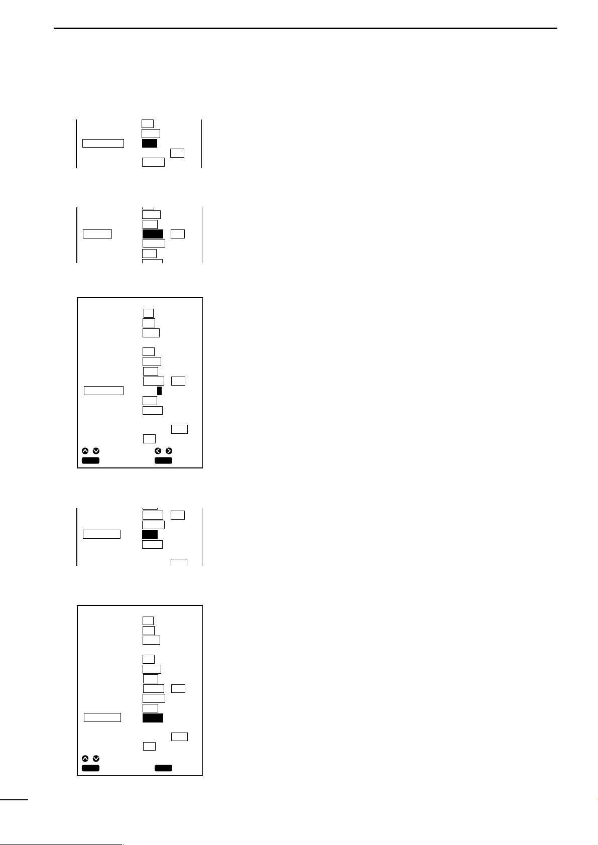
65
5
INITIAL SETTING AFTER INSTALLATION
This item allows you to make a selection between two options on graphic
indication on the navigation monitor screen:
•NOR: Normal indication
•REVS: Reverse indication
This item allows you to make a selection between two options on Time indication on the navigation monitor screen:
•LOCAL: Local standard time
•GMT: Greenwich Mean Time (UTC)
The following describes how to set the offset time between UTC (Universal
Time Coordinated) and the standard time of a time zone.
The offset time of the system defaults to “+9”.
q Select “SETTING” on the Setting Menu screen using the [UP] or [DOWN] key
and press the [SET] key.
The SETTING screen will appear.
w Select “OFFSET TIME” using the [UP] or [DOWN] key and press the [SET] key.
e Move to the time difference setting field using the [LEFT] or [RIGHT] key.
The selected item is highlighted in yellow.
r Enter the desired value into the time difference setting field using the [UP] or
[DOWN] key and press the [SET] key.
The setting is saved.
t When you finish setting the offset time, press the [MENU] key.
You will return to the SET MODE screen.
This item allows you to make a selection between two ship speed signal sensing
options.
•POS: Signals received by the GPS receiver are used to read the ship speed.
•SENS: Signals detected b y the sensor are used to read the ship speed.
The following describes how to correct the ship speed for diff erence between
the actual speed and the speed sensor reading.
q Select “SETTING” on the SET MODE screen using the [UP] or [DOWN] key and
press the [SET] key.
The SETTING screen will appear.
w Select “SPEED ADJ” using the [UP] or [DOWN] key and press the [SET] key.
e Enter the pulse rate of the speed sensor into the pulse rate setting field using
[UP] or [DOWN] key and press the [SET] key.
* When using an optional sensor, EX-1622 (transom type speed/temperature sen-
sor), set the pulse rate to “24000 P/NM”.
When using an optional transducer, EX-1010 (through-the-hull type transducer
with speed/water temperature sensor), set the pulse rate to “22000 P/NM”.
* If the above setting causes an error to occur, adjust the pulse rate while refer-
ring to the speed reading displayed on the screen.
r When you finish correcting the ship speed, press the [MENU] key.
You will return to the SET MODE screen.
| COMPASS IND
| TIME REF
| OFFSET TIME
| SPEED DATA
| SPEED ADJ
DATUM
BEARING
COMPASS IND
TIME REF
OFFSET TIME
123
TRUE
NOR
LOCAL
+ 9 : 00
MAG
REVS
GMT
BEARING
COMPASS IND
TIME REF
OFFSET TIME
SPEED DATA
TRUE
NOR
LOCAL
+ 9 : 00
POS
MAG
REVS
GMT
SENS
SETTING
AUTO GAIN
DRAFT ADJ
TEMP ADJ
DATUM
BEARING
COMPASS IND
TIME REF
OFFSET TIME
SPEED DATA
SPEED ADJ
NMEA OUT
BOD OUT
ON
7.5 FT
+ 2.4 °F
TEMP
123
TRUE
NOR
LOCAL
+09 : 00
POS
24000 P/
SPEED
V1 . 5
WP
OFF
. °F
MAG
REVS
GMT
SENS
NM
0 . 0KT
V2 . 2
SHIP
CLR
CANC
SEL
ADJ
SET
SET
TIME REF
OFFSET TIME
SPEED DATA
SPEED ADJ
NMEA OUT
LOCAL
+ 9 : 00
POS
24000 P/
SPEED
V1 . 5
GMT
SENS
NM
0 . 0KT
V2 . 2
SETTING
AUTO GAIN
DRAFT ADJ
TEMP ADJ
DATUM
BEARING
COMPASS IND
TIME REF
OFFSET TIME
SPEED DATA
SPEED ADJ
NMEA OUT
BOD OUT
ON
7.5 FT
+ 2.4 °F
TEMP
123
TRUE
NOR
LOCAL
+ 9 : 00
POS
24000 P/
SPEED
V1 . 5
WP
OFF
. °F
MAG
REVS
GMT
SENS
NM
0 . 0KT
V2 . 2
SHIP
CLR
CANC
ADJ
SET
SET
Page 69

66
5
INITIAL SETTING AFTER INSTALLATION
This item allows you to make a selection between two versions of external
NMEA0183 supported by the system:
•V1.5: Version 1.5
•V2.2: Version 2.2
This item allows you to make a selection between two reference points of the
azimuth to the destination or next turning point:
•WP: The azimuth from the starting point to the next turning point is
applied on NMEA OUT. (default)
•SHIP: The azimuth from the current ship position to the destination is
applied on NMEA OUT.
| NMEA OUT
| BOD OUT
SETTING
AUTO GAIN
DRAFT ADJ
TEMP ADJ
DATUM
BEARING
COMPASS IND
TIME REF
OFFSET TIME
SPEED DATA
SPEED ADJ
NMEA OUT
BOD OUT
ON
7.5 FT
+ 2.4 °F
TEMP
123
TRUE
NOR
LOCAL
+ 9 : 00
POS
24000 P/
SPEED
V1 . 5
WP
OFF
. °F
MAG
REVS
GMT
SENS
NM
0 . 0KT
V2 . 2
SHIP
CLR
CANC
SEL
SET
SET
SETTING
AUTO GAIN
DRAFT ADJ
TEMP ADJ
DATUM
BEARING
COMPASS IND
TIME REF
OFFSET TIME
SPEED DATA
SPEED ADJ
NMEA OUT
BOD OUT
ON
7.5 FT
+ 2.4 °F
TEMP
123
TRUE
NOR
LOCAL
+ 9: 00
POS
24000 P/
SPEED
V1 . 5
WP
OFF
. °F
MAG
REVS
GMT
SENS
NM
0 . 0KT
V2 . 2
SHIP
CLR
CANC
SEL
SET
SET
Page 70

67
5
INITIAL SETTING AFTER INSTALLATION
5-5 RANGE SELECTION
This section describes how to register your most-used depth ranges among
31 depth ranges.
q Select “Range Selection” on the SET MODE screen using the [UP] or [DOWN]
key and press the [SET] key.
The Depth Range Selection screen will appear.
w Select a desired range using the [UP]/[DOWN] or [LEFT]/[RIGHT] k e y and press
the [SET] key.
The selected range turns white.
e Repeat step w until all of your desired ranges turn white.
Ranges you have not selected are show in red.
To undo your selection, press the [CLR] key.
r When you finish range selection, move the cursor to “END” and press the [SET]
or press the [MENU] key.
The selections are saved, and you will return to the SET MODE screen.
RESET ALL SETTINGS ?
SET MODE
UNIT
SETTING
RANGE SELECTION
ALL RESET
CLR
CANC OK
SET
Any changes you made to the system parameters can be restored to the original settings (defaults).
To do this, proceed as follows.
q Select “ALL RESET” on the SET MODE screen using the [UP] or [DOWN] key
and press the [SET] key.
The selected item turns blue and a message will appear, indicating that you are
going to reset all the setting items.
w Press the [SET] key.
All the setting items default to their original state.
• Press [CLR] to cancel the function.
5-6 ALL RESET
WARNING:
When “All Reset” is selected and the [SET] key is pressed, all of your settings,
including registered routes and marks, are lost and cannot be restored.
Standard depth ranges
Units of Depth range
m (meters)
FT (feet)
FM (fathoms)
5
240
20
600
3
120
10
260
40
700
5
130
20
280
60
800
10
140
30
300
80
900
15
150
40
320
100
1000
20
160
50
350
120
1100
25
180
60
400
140
1200
30
200
70
440
160
1300
35
220
80
450
180
1400
40
240
100
480
200
1500
50
260
120
500
220
1600
60
280
140
520
240
1700
70
300
160
560
260
1800
80
320
180
600
300
1900
90
340
200
640
400
2000
100
350
220
500
110
(default)
RANGE SELECTION
UNIT: FT
20 40 60 80 100
120 140 160 180 200
220 240 260 300 400
500 600 700 800 900
1000 1100 1200 1300 1400
1500 1600 1700 1800 1900
2000 END
CANC
SEL
SET
CLR
Ranges you have selected: White
Ranges you have not selected: Red
SET
Page 71

68
6
INSTALLATION PROCEDURE
6-1 Overall connection
diagram
Install the system properly according to the instruction of this manual to
ensure optimum performance and stable operation of the system
Prior to commencing installation work, make sure that the system package comes
complete with the accessories listed in the “Standard accessories” section on the
first page of the manual.
Ground
Battery
11 to 30 VDC
GPS antenna
Red: + Black: –
PWR
GND
NMEA
DGPS
NMEA IN
External navigator
NMEA OUT
FF-89, MR-61/610,
VP-21 or the like
GPS ANT
TRANSDUCER
(Option)
RD-200
Differential GPS
receiver (Option)
EX-1622
Transom-
type
transducer
(Option)
EX-1010
Through-hull type
transducer
(Option)
Install the main unit of the system in such an area that
q Is situated forward of the steering wheel and is easy for the steersman to
observe the display of the unit;
w Is distant as far as possible from devices forming a magnetic field, such as a
loudspeaker and power transformer, or devices sensitive to a magnetic field,
such a magnetic compass and magnetic tape; and
e Is not exposed to rainwater, spray of water or direct sunlight.
6-2 Installation procedure
Å Installation place of the main unit
Page 72

69
6
INSTALLATION PROCEDURE
186 mm; 76⁄16″
37.5 mm;115⁄32″
103 mm;4″
125.65 mm;415⁄16″
196 mm; 723⁄32″ 125 mm;429⁄32″
203 mm;8″
75 mm;
31
⁄32″
234.5 mm;9
7
⁄32″
178 mm;7″
234.5 mm;9
7
⁄32″
160 mm;65⁄16″
91 mm;3
19
⁄32″
Tilting lever
Tilting
Removing the unit from the stand
The stand can also be attached to the top of the unit.
*Protrusions not included
MARINEPLOTTER/SOUNDER
fp-561
COMBINE
MARINEPLOTTER/SOUNDER
fp-561
COMBINE
ı Installing the main unit
Install the main unit as follows.
q Choose the installation position of the stand of the main unit.
w Mark center points through the four mounting holes of the stand and then drill a
hole of 5 mm in diameter at each of the marked points.
e Secure the stand with the self-tapping screws, flat washers and spring washers.
r Mount the main unit onto the stand and secure it with two mounting screws.
t Push the tilting lever down and adjust the angle of the unit as appropriate; then
return the lever to the original position.
Page 73

70
6
INSTALLATION PROCEDURE
This system operates from an 11 to 30 VDC power source.
Connect the power cable as follows.
q Connect the connectorless end of the cable to the battery as shown in the over-
all connection diagram (☞ P. 68).
* Exercise care to avoid reverse connection in polarity. Reverse connection may
cause a blowout of the fuse or damage to the system.
w Connect the connector end of the cable to the PWR connector located on the
rear panel of the system.
Be sure to ground the system properly.
Failure to do so may cause a malfunction or fault of the system.
To establish a ground for the system, use a ground cable of adequate size to connect between the GND terminal and the engine block or hull in the shortest distance.
Never connect ground cables for other electronic devices to the grounding
mass that is used to ground the system.
Since GPS signals reaches the system from a distance of several hundred
miles, noise sources near the system may result in failure to take full advantage of the system.
Noise sources include generator, fishfinder, radar, computer and fluorescent lamp.
The system should be placed apart from these noise sources as far as possible or
the noise sources except the generator should not be used during the use of the
system.
Take the following measures against noises due to the generator among others.
q Prepare an electrolytic capacitor and a film capacitor having the follo wing ratings
depending on the system’s power source voltage.
w Solder the electrolytic capacitor and film capacitor in parallel with each other.
And as shown in the figure on the left, connect lead wires to the capacitor combination and cover the lead connections with silicon rubber to av oid current leakage.
* The lead wires must not exceed 4 in (10 cm) in length.
e Connect the positive end of the capacitor combination to the generator output
terminal and the negative end to the grounding mass such as the engine block.
Ç Connecting the power cable
Î Connecting a ground cable
6-3 Measures against noises
from the generator
Silicon rubber
Film capacitor
Electrolytic capacitor
Must be within 10 cm each
+
_
PWR connector on the rear panel
Power source voltage
12V
24V
Electrolytic capacitor
2,200µF 35WV
2,200µF 50WV
Film capacitor
4.7µF 400WV
4.7µF 400WV
Page 74

71
6
INSTALLATION PROCEDURE
6-4 Installing the GPS antenna
When installing the GPS antenna, observe the following.
q Install the antenna at the top of the highest and obstacle-free position of the
ship.
w Install the antenna in a horizontal position.
Install the antenna with a extention pipe and the horse bands as follows.
e Install the antenna at a position at least 1 m away from the main unit or other
electronic devices.
r Do not paint the antenna.
Doing so will deteriorate the sensitivity of the antenna due to metal components
of a paint.
t Install the antenna and route the antenna cable at some distance from other
antennas or antenna cables (such as a TV antenna and radio), metal objects,
and the main unit.
It is recommended not to use a TV during the use of the system.
Horse bands
(supplied)
Ratchet mount
(Sold separately.
Ask your boat
dealer or marina.)
1 in (14 threads)
•Install on must
•Install on a deck or roof
NOTE: Be sure to
screw tightly.
Page 75

72
6
INSTALLATION PROCEDURE
6-5 Installing an optional transducer
Various types of transducers and ship speed/water temperature sensors are
available as options to suit your application.
The performance of the fishfinder greatly depends on the installation posi-
tion of the transducer.
Transducers are mainly divided into two types: the through-the-hull type and the
transom type.
Install the transducer in the following area.
q Area where the possibility of on-screen voids due to air bubbles or water turbu-
lence is minimized;
w Area that resists being exposed to noises from the engine;
e Area where the transducer is kept horizontal e ven if the ship runs at high speed;
(The optimum installation position of the transducer is said to be at a distance
of a half or one-third of the ship length from the stern for low-speed small ships,
and to be located close to the stern for high-speed ships.)
r Area where the bottom plate is the thinnest in the vicinity of the stern (for inner-
hull type transducer; the ultrasonic decays when it passes through the bottom
plate).
¡ Do not plug or unplug a cable into of from the TRANSDUCER connector.
Doing so may cause damage to the ship speed sensor.
¡ A transducer must be installed by a shipbuilder or an expert installer.
Å Optional transducers and acces-
sories
ı Installation position
EX-1010
EX-1622
RD-200
Through-the-hull type transducer
(600W, 2 frequencies, metal enclosure, built-in sensor)
Transom type transducer
(600W, 2 frequencies, plastic enclosure, built-in sensor)
DGPS beacon receiver
Bottom plate
of the ship
To the TRANSDUCER terminal
on the real panel of FP-561
Installation example of EX-1010
Page 76

73
6
INSTALLATION PROCEDURE
6-6 Connecting an external
navigator
6-7 DGPS
An external navigation equipments can be connected to the NMEA connector on the rear panel of the system.
Connect a 4-pin microphone connector to the NMEA connector and plug the data
line in the 1-pin connector and the data return line in the 2-pin connector.
When using an external navigator, set “Positioning Equipment” to “NMEA” on the
Positioning Menu screen (☞ P. 34).
When sending positioning data obtained from the build-in GPS navigator to optional radar MR-61/610, Marine plotter VP-21 or other devices, plug these devices to
the NMEA connector (3-pin/4-pin) on the rear panel of the system while referring to
the overall connection diagram on page 70.
The DGPS is a newly established system intended to impro ve the positioning
precision of the GSP.
Connecting RD-200, a DGPS beacon receiver, allows the system to receive correction data from a land DGPS reference station, thereby enabling the positioning
precision to be further improved.
The nominal positioning precision is 100 m when only the GPS is used, but using
the DGPS leads to the nominal precision of 10 m.
* For details, see the RD-200 Instruction Manual.
NMEA OUT+
NMEA OUT_
NMEA IN_
NMEA IN+
4
3
1
2
NMEA connector on the rear panel
Page 77

74
7
MAINTENANCE
7-1 Maintenance and
inspection
7-2 Replacing the fuse
This system is designed to be easy to maintain for the operator. Proper maintenance allows to the system to be kept in a optimum state and prevents the possibility of malfunctions.
As a high voltage is used in the system, be sure to read the Safety Notice on page1
before commencing maintenance work.
q To remove dirt from the cover or key panel, wipe it using a soft cloth damped
with a water-diluted detergent.
w To clean the TFT display, wipe it using a soft cloth damped with an anti-static
agent or water.
e Check cable connections and the GND terminal for contamination and loose-
ness.
Also check cables for wear.
r Check the transducer surface, cables and connectors for rust or adhesion of
marine organisms such as algae.
To clean the transducer surface, wipe it using a soft brush damped with a detergent.
t The main unit of the system contains a lithium battery that retains data in RAM.
This backup battery has a life of approx. five (5) years.
If the battery is completely dead, registered navigational marks and routes are
lost.
If these symptoms appear, contact your dealer or our local sales office.
All the circuits of the system are fuse-protected.
If the [POWER] key is inoperative, proceed as follows.
q Open the fuse holder of the power cable, remove the burnt fuse.
w Locate and remove the cause of a fuse blowout, install a new fuse.
Use the replacement fuse rated at 3 A.
* Fuses are contained in the main unit.
If replacing the fuse of the power cable fails to remove the symptom, contact your dealer or our service personnel for inspection.
Page 78

75
8
SPECIFICATIONS
GENERAL
¡Display :5.6″ TFT color LCD (320 × 234 dots)
¡Power supply : 11 to 33 VDC
¡Power consumption : Less than 22 W (Less than 1.8 A at 12 VDC)
¡Weight : Approx. 2.2 kg; 4 lb 14 oz
¡Operating ambient temperature :0 °C to +50°C, +32°F to +122°F
PLOTTER
¡Track indication : (1) Number of available reduced scales : 16
(2)Tracking intervals : 5 sec. to 60 min.
/ in increments of 0.01 to 9.99 (common for all units)
(3)Track plotting points : 5,000 max. (7 colors selectable)
¡Data indication : Coastlines, place-names (stored in ROM card)
¡Navigation calculation : (1) Latitude and longitude of current ship position
(2)Distance, required time, deviation out of course
(3)Latitude and longitude of cursor position, azimuth, distance
(4)Time
¡Number of registered marks : 500 max.
¡Alarms : Range alar m, arr ival alarm
¡Available screens : (1) Coastline screen
(2)Navigation monitor screen
(3)Positioning information screen
GPS RECEIVER
¡Receive system : 12 channels, all-in-one view
¡Receive Frequency : 1575.42 MHz
¡Following efficiency : Speed: Less than 500 m/S, Acceleraration: Less than 4 G
¡Measuring accuracy : 15 m RMS (DOP≤6)
The precision may deteriorate to 100 m max. depending on the policies of the
U.S. Department of Defense.
Page 79

76
8
SPECIFICATIONS
SOUNDER
¡Transmission frequency : 50/200 kHz
¡Output power : 500 W (RMS)
¡Available screens : (1) Standard screen
(2)Standard + A scope screen
(3)Two-frequency screen
(4)Standard + bottom rock screen
(5)Standard + marker zoom-in screen
¡Image feed : 6 stages including Halt
¡Alarms : (1) Shallow alarm
(2)Depth alarm
(3)Fish alarm
¡Units of depth of water : m (meter), FT (feet), FM (fathom)
¡Units of water temperature : 0 to +40°C, +32 to 104°F
¡Ultrasonic reflection levels : 8 colors used
¡Depth ranges : m : 5, 10, 20, 30, 40, 50, 60, 70, 80, 100,120, 140, 160, 180, 200, 220, 240,
260, 280, 300, 320, 350, 400, 450, 480, 500, 520, 560, 600, 640
FT : 20, 40, 60, 80, 100, 120, 140, 160, 180, 200, 220, 240, 260, 300, 400,
500, 600, 700, 800, 900, 1000, 110, 1200, 1300, 1400, 1500, 1600, 1700,
1800, 1900, 2000
FM : 3, 5, 10, 15, 20, 25, 30, 35, 40, 50, 60, 70, 80, 90, 100, 110, 120, 130,
140, 150, 160, 180, 200, 220, 240, 260, 280, 300, 320, 340, 350
¡Phase shift variable range : 0 to 640 m (0 to 2000 FT, 0 to 3200 FM) in increments of one step
¡Zoom-in ranges : m : 5, 10, 20, 40
FT : 15, 30, 60, 120
FM : 3, 5, 10, 20
OTHER
¡Units of ship speed : KT, km/h, Ml/h
¡Units of distance : km, NM, Ml
¡LCD brightness : 16 stages
¡External data input : (1) NMEA0183
(2)Water temperature/ship speed data
(3)Input from DGPS
¡Data output : NMEA0183 (GGA, GLL, XTE, AAM, VGT, BOD, WPL, BWC)
Synchronous serial transfer at 4800 bps
Ver 1.5/2.2
*Appearance and specifications of the system may be subject to change without notice.
Page 80

77
9
DATUM (GEODETIC REFERENCE) CODE
■ Datum (Geodetic reference) table
0 : WGS 84—Default
1 : Ethiopia, Sudan
2 : Burkina Faso
3 : Cameroon
4 : Ethiopia
5 : Mali
6 : Senegal
7 : Sudan
8 : Somalia
9 : Bahrain
10 : Saudi Arabia
11 : Cocas Islands
12 : Antigua
13 : Botswana, Lesotho, Malawi, Swaziland, Zaire,
Zambia, Zimbabwe
14 : Botswana
15 : Burundi
16 : Lesotho
17 : Malawi
18 : Swaziland
19 : Zaire
20 : Zambia
21 : Zimbabwe
22 : Kenya, Tanzania
23 : Ascension Island
24 : Iwo Jima
25 : St Helena Island
26 : Tern Island
27 : Marcus Island
28 : Australia & Tasmania
29 : Australia & Tasmania
30 : Djibouti
31 : Efate & Erromango Island
32 : Bermuda
33 : Guinea–Bissau
34 : Colombia
35 : Indonesia
36 : Camp Area Astro Antarctica
(McMurdo Camp Area)
37 : Argentina
38 : Phoenix Islands
39 : South Africa
40 : Bahamas, Florida
41 : Tunisia
42 : New Zealand
43 : Paraguay
44 : Brazil
45 : Guinea
46 : Indonesia
(Sumatra)
47 : Gizo Island
48 : Easter Island
49 : Austria, Belgium, Denmark, Finland, France, Italy,
West Germany, Gibraltar, Greece, Luxembourg,
Netherlands, Norway, Portugal, Spain, Sweden,
Switzerland
50 : Austria, France, West Germany, Netherlands,
Denmark, Switzerland,
51 : Iraq, Israel, Jordan, Lebanon, Kuwait, Saudi Arabia,
Syria
52 : Cyprus
53 : Egypt
54 : England, Channel Islands, Ireland, Scotland,
Shetland Islands
55 : Finland, Norway
56 : Greece
57 : Iran
58 : Italy
(Sardinia)
59 : Italy (Sicily)
60 : Malta
61 : Portugal, Spain
62 : Austria, Finland, Netherlands, Norway, Spain,
Sweden, Switzerland
63 : Leeward Islands
64 : Republic of Maldives
65 : New Zealand
66 : Graciosa Base SW 1948 Azores
67 : Guam
68 : Indonesia
69 : Guadalcanal Island
70 : Afghanistan
71 : Iceland
72 : Hong Kong
73 : Taiwan
74 : Bangladesh
75 : India, Nepal
76 : Thailand, Vietnam
77 : Thailand
78 : Ireland
79 : South Georgia Islands
80 : Diego Garcia
81 : Johnston Island
82 : Sri Lanka
83 : Kerguelen Island
84 : West Malaysia & Singapore
85 : Caroline Islands
86 : Cayman Brac Island
87 : Ghana
88 : Liberia
89 : Luzon Philippines
(Excluding Mindanao)
90 : Luzon Philippines (Mindanao)
91 : Mahe Island
92 : Ethiopia
(Eritrea)
93 : Morocco
94 : Midway Islands
95 : Cameroon
96 : Nigeria
97 : Montserrat (Leeward Islands)
98 : Gabon
99 : Oman (Masirah Island)
100 : Saudi Arabia
101 : United Arab Emirates
102 : Trinidad & Tobago
103 : Antigua, Barbados, Barbuda, Cuba, Caicos Islands,
Dominican Republic, Grand Cayman, Jamaica,
Turks Islands
104 : Belize, Costa Rica, El Salvador, Guatemala,
Honduras, Nicaragua
105 : Canada
106 : CONUS
107 : CONUS
(East of Mississippi River) including Louisiana,
Missouri, Minnesota
108 : CONUS
(West of Mississippi River)
Page 81

78
9
DATUM (GEODETIC REFERENCE) TABLE
109 : Alaska
110 : Bahamas
(Except San Salvador Island)
111 : Bahamas (San Salvador Island)
112 : Canada (Alberta, British, Columbia)
113 : Canada (Manitoba, Ontar io)
114 : Canada
(New Brunswick, Newfoundland, Nova Scotia, Quebec)
115 : Canada (Northwest Territor ies, Saskatchewan)
116 : Canada (Yukon)
117 : Canal Zone
118 : Cuba
119 : Greenland
(Hayes Peninsula)
120 : Mexico
121 : Alaska, Canada, CONUS
122 : Central America, Mexico
123 : Azores (Cor vo & Flores Islands)
124 : Egypt
125 : Hawaii, Kauai, Maui, Oahu
126 : Hawaii
127 : Kauai
128 : Maui
129 : Oahu
130 : Oman
131 : England, Isle of Man, Scotland, Shetland Islands,
Wales
132 : England
133 : England, Isle of Man, Wales
134 : Scotland, Shetland Islands
135 : Wales
136 : Canar y Islands
137 : Pitcair n Island
138 : Bur kina Faso & Niger
139 : Congo
140 : Porto Santo, Madeira Islands
141 : Bolivia, Chile, Colombia, Ecuador, Guyana, Peru,
Venezuela
142 : Bolivia
143 : Chile
(Northern, Near 19˚ S)
144 : Chile (Souther n, Near 19˚ S)
145 : Colombia
146 : Ecuador
147 : Guyana
148 : Peru
149 : Venezuela
150 : Chile
(Southern, Near 53˚ S) (Hito XVIII)
151 : Puerto Rico, Virgin Islands
152 : Qatar
153 : Greenland (South)
154 : Mascarene Islands
155 : Italy
(Sardinia)
156 : Espir ito Sano Island
157 : Azores (Sao Miguel, Santa Maria Islands)
158 : East Falkland Island
159 : Namibia
160 : Salvage Islands
161 : SGS 85
162 : Argentina, Bolivia, Brazil, Chile, Peru, Colombia,
Ecuador, Guyana, Paraguay, Trinidad & Tabago,
Venezuela
163 : Argentina
164 : Bolivia
165 : Brazil
166 : Chile
167 : Colombia
168 : Ecuador
169 : Ecuador (Baltra, Galapagos)
170 : Guyana
171 : Paraguay
172 : Peru
173 : Trinidad & Tobago
174 : Venezuela
175 : Singapore
176 : Madagascar
177 : Br unei, East Malaysia
(Sabah, Sarawak)
178 : Tokyo–MEAN FOR Japan, Korea, Okinawa
179 : Tokyo–Japan
180 : Tokyo–Korea
181 : Tokyo–Okinawa
182 : Tristan da Cunha
183 : Viti Levu Island
184 : Marshall Islands
185 : Wake Atoll
186 : WGS 1972–Global Definition
187 : Yacare–Uruguay
188 : Zander ij–Suriname
Page 82

79
Page 83

80
Page 84

6-9-16 Kamihigashi, Hirano-ku, Osaka 547-0002, Japan
A-5595G-1EX-q
Printed in Japan
© 1999 Icom Inc.
 Loading...