

Page 1
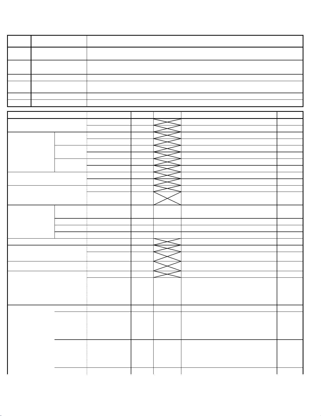
Command List
y
g
a
Command
type
Transceive
Read out
ACK
Mode
OK ACK
NG ACK
Program frequency
Mode setting
Ffrequency Read out
Mode Read out
Memory Write
Memory→VFO
Offset frequency Read out
Program offset frequency Set 0D 3
Scan Read out
Scan setting Scan cancel Set 0E 00 00 1
Communication Direction Meaning
ID1 -> PC
PC -> ID1
ID1 -> PC
PC -> ID1
ID1 -> PC
ID1 -> PC
FM
Digital voice
Digital data
Memory Ch
Call C1 Transceive 09 01 00 01 2
Call C2 Transceive 09 01 00 02 2
Call C3 Transceive 09 01 00 03 2
Program Scan Start Set 0E 02 xx 1
Memory Scan Start Set 0E 22 xx 1
Mode Select Scan Start Set 0E 24 xx 1
Transfers the command automaticall
not reply with an ACK
The command request that reads out the setting values inside the ID-1. The ID-1 resplies with the setting
values with ACK command.
The ACK command that responds to the read-out command.
The command that sets the settin
NG ACK to indicate whether it has accepted the setting values or not.
Responds with an OK ACK when the setting has been carried out correctly.
Responds with an NG ACK when the setting has not been carried out correctly.
Command Type Command Subcommand Data length
Transceive 00 1 - 2
Set 05 1 - 2
Transceive 01 05 01 2
Set 06 05 01 2
Transceive 01 D0 01 2
Set 06 D0 01 2
Transceive 01 D1 01 2
Set 06 D1 01 2
Read out 03 0
ACK 03 5
Read out 04 0
ACK 04 xx 01 2
Transceive
Set 0A 0
Read out 0C 0
ACK/Transceive 0C 3
Read out 0E 0
ACK/Transceive
according to the status, and the side that receives the command d
values in the inside the ID-1. The ID-1 replies with an OK ACK or
DataOperation
BCD (5bytes) (See frequency data details)
BCD (5bytes) (See frequency data details)
BCD (5bytes) (See frequency data details)
Type of Mode ( See Mode setting for details )
09 00 0 ,BCD BCD,BCD 2
PA=100 PB=101
BCD (3bytes)
( See Offset frequency data details)
BCD (3bytes)
( See Offset frequency data details)
0E ww xx yy 2
Scan Mode
( See
Scan setting
details )
Scan
direction
UP=00
DN=01
Scan
direction
UP=00
DN=01
Scan
direction
UP=00
DN=01
Scan status
RUN=00
PAUSE=01
(00 - 99, 100, 101 Ch)
Copyright © 2002-2003 Icom. Inc Distribution of this document is PROHIBITED 16
Page 2

Scan
direction
UP=00
DN=01
Copyright © 2002-2003 Icom. Inc Distribution of this document is PROHIBITED 26
Page 3

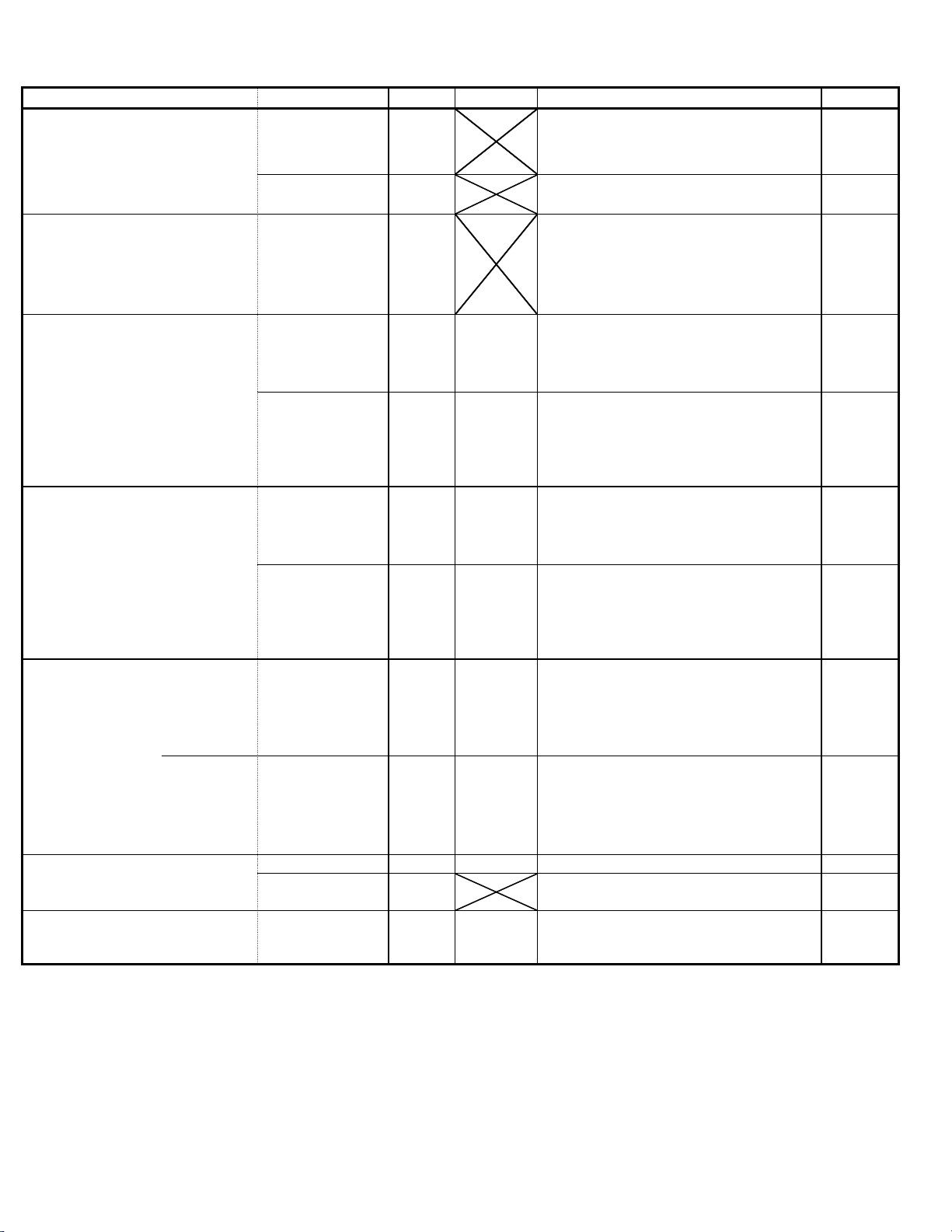
Command Type Command Subcommand Data Length
e
Scan seting PRIO Scan Start Set 0E 42 xx 1
Scan
direction
UP=00
DN=01
RP (DUP) Read out
RP (DUP) programming Set 0F ww 0
TS Read out
TS programming
AF VOL Knob Read out
AF VOL Knob setting
SQL Knob Rread out
SQL Knob Setting
RF Power Read out
RF Power setting
Noise SQL Open/Close Read out
S-meter Level Read out Read out 15 02 0
AFC Read out
AFC Setting
Copyright © 2002-2003 Icom. Inc Distribution of this document is PROHIBITED 36
Read out 0F 0
ACK/Transceive 0F ww 0
RP typ
(See RP
setting)
Simp.=10 ←Simplex
RP-=11 ←RP-(DUP-)
RP+=12 ←RP+(DUP+)
RPS=13 ←RPS
Read out 10 0
ACK/Transceive 10 ww 0
TS type
(See Setting
)
Set 10 ww 0
5kHz=00
10kHz=01
12.5kHz=02
20kHz=03
25kHz=04
50kHz=05
100kHz=06
6.25kHz=07
Read out 14 01 0
ACK/Transceive 14 01 0 ,BCD BCD,BCD 2
Set 14 01 0 ,BCD BCD,BCD 2
Read out 14 03 0
ACK/Transceive 14 03 0 ,BCD BCD,BCD 2
Set 14 03 0 ,BCD BCD,BCD 2
Read out 14 0A 0
ACK/Transceive 14 0A 0 ,BCD BCD,BCD 2
Set 14 0A 0 ,BCD BCD,BCD 2
Hi Power =255
Low Power =0
Read out 15 01 0
ACK/Transceive 15 01 xx 1
close=00
open=01
ACK/Transceive 14 02 0 ,BCD BCD,BCD 2
Indicates the S-meter resolution
Read out 16 4A 0
ACK/Transceive 16 4A xx yy 2
OFF=00
ON=01
Set 16 4A xx 1
OFF=00
ON=01
Data Operation
(00 - 255 level)
(00 - 255 level)
(00 - 255 level)
(00 - 255 level)
(00 - 255 level)
(00/255 level)
(00 - 255 level)
center=00
up=01
dn=02
Page 4
Operation Data
,
,
Power Switch Read out
Power Switch Setting
ID read out
Memory Channnel Information Read out
Memory Ch. Info. Setting Memory Clear
Memory write Set 1A 00 xx yy, yy zz - 55
Memory Channel SKIP Read out Read out
Memory Channel SKIP Setting
Command Type Command Subcommand Data Length
Read out 18 0
ACK/Transceive 18 xx 1
Set 18 xx 1
Read out 19
ACK/Transceive 19 25, 06, RR, RR, CC,CC, SS,SS,SS 9
Read out 1A 00 xx yy, yy 3
ACK 1A 00 xx yy, yy zz - 55
Set 1A 00 xx yy, yy zz - 4
ACK/Transceive
Set
1A
1A
1A
During Power Switch read out, the number of
preamble FE required is 15. When there is no ACK
the command is repeated 15 times.
(See Power Switch Setting details)
OFF=00
ON=01
During Power Switch read out, the number of
preamble FE required is 15. When there is no ACK
the command is repeated 15 times.
ID read out is used also for identifying control software
version. Preamble FE must be repeated 15times when
begin reading, will repeat 15times if no response
received.
25,06= fixed values (16h)
RR, RR=Rev. information
CC, CC=version 01=USA
SS, SS, SS=firmware check sum information
xx= M/C
yy, yy= Ch. number
(See Command 1A 00 for details)
xx= M/C
yy, yy= Ch. number
zz - = Memory Ch. Info Contents
(See Command 1A 00 for details)
xx= M/C
yy, yy= Ch. number
zz= 0xff (Memory Ch. clear value)
(See Command 1A 00 for details)
xx= M/C
yy, yy= Ch. number
zz - = Memory Ch. Info Setting Contents
(See Command 1A 00 for details)
01 0
xx 1
(See Memory Ch. SKIP Setting for details)
01 xx 1
OFF=00
ON=01
Copyright © 2002-2003 Icom. Inc Distribution of this document is PROHIBITED 46
Page 5

Operation Data
TONE Read out
Command Type Command Subcommand Data Length
Read out 1A 02 0
ACK/Transceive 1A 02 xx yy 2
(See TONE
Setting
details)
TONE Setting
MUTE Read out
MUTE Setting
MONI Read out
Current Status Read out
Current Status Setting
Memory Channel Read out
Memory Channel Setting
Call channel read out Read out 1A 04 02 1
CALL Channel Setting
VFO/Memo Status Read out
VFO/Memo Status Setting
TX INH Read out
TX INH Setting
Set 1A 02 xx 1
OFF=00
TONE=01
PBEEP=02
TSQL=03
Read out 1A 03 00 1
ACK/Transceive 1A 03 00 yy 2
Setting 1A 03 00 yy 2
Read out 1A 03 01 1
ACK/Transceive 1A 03 01 yy 2
Setting 1A 03 01 yy 2
Read out 1A 04 00 1
ACK/Transceive 1A 04 00 yy 2
(See Current Status Setting details)
Setting 1A 04 00 yy 2
Read out 1A 04 01 1
ACK/Transceive 1A 04 01 0 ,BCD BCD,BCD 3
(See Current Status Setting details)
Setting 1A 04 01 0,BCD BCD,BCD 3
ACK/Transceive 1A 04 02 BCD,BCD 2
Setting 1A 04 02 BCD,BCD 2
Read out 1A 04 03 1
ACK/Transceive 1A 04 03 yy 2
(See VFO/Memo Status Setting details)
Setting 1A 04 03 yy 2
Read out 1A 05 00 1
ACK/Transceive 1A 05 00 yy 2
Setting 1A 05 00 yy 2
Copyright © 2002-2003 Icom. Inc Distribution of this document is PROHIBITED 56
PBEEP
Call Rx=01
No RX=00
OFF=00
ON=01
OFF=00
ON=01
OFF=00
ON=01
OFF=00
ON=01
VFO=00
Memo=01
CALL=02
(00 - 99, 100, 101Ch)
PA=100 PB=101
(See CALL Ch. Setting details)
(01 - 03Ch.)
VFO=00
Memo=01
(See TX INH Setting details)
Tx INH=00
Page 6

TX Enable=01
Copyright © 2002-2003 Icom. Inc Distribution of this document is PROHIBITED 66
Page 7

Operation Data
BEEP Read out
BEEP Setting
Cooling FAN Read out
Cooling FAN setting
Auto Repeater Read out
Auto Repeater Setting
Dimmer Read out
Dimmer Setting
Scan Resume Timer Read out
Scan Resume Timer Setting
Standby Beep read out
Standby Beep Setting
Memory Name Read out
Memory Name Setting
All Status Read Read out
All Memory Clear ACK
All Memory Clear Setting
Command Type Command Subcommand Data Length
Read out 1A 05 02 1
ACK/Transceive 1A 05 02 yy 2
(See BEEP Setting details)
Setting 1A 05 02 yy 2
OFF=00
ON=01
Read out 1A 05 03 1
ACK/Transceive 1A 05 03 yy 2
(See Cooling FAN Setting details)
Setting 1A 05 03 yy 2
AUTO=00
ON=01
Read out 1A 05 04 1
ACK/Transceive 1A 05 04 yy 2
(See Auto Repeater Setting details)
Setting 1A 05 04 yy 2
OFF=00
ON2=01
ON1=02
OFF=00
ON=01
Read out 1A 05 05 1
ACK/Transceive 1A 05 05 yy 2
(See Dimmer Setting details)
Setting 1A 05 05 yy 2
Bright=00
Dark=01
OFF=02
Read out 1A 05 06 1
ACK/Transceive 1A 05 06 yy 2
(See scan Resume Timer Setting details)
Setting 1A 05 06 yy 2
P-2=00
T-5=01
T-10=02
T-15=03
Read out 1A 05 07 1
ACK/Transceive 1A 05 07 yy 2
(See Standby Beep Setting details)
Setting 1A 05 07 yy 2
OFF=00
ON=01
Read out 1A 06 0
ACK/Transceive 1A 06 xx 1
(See Memory Setting details)
Setting 1A 06 xx 1
OFF=00
ON=01
Read out 1A 09 0
ACK -- -- --
ACK/Transceive 1A 0A 41, 4C, 4C 3
Setting 1A 0A 41, 4C, 4C 3
The ID-1 outputs all command ACK values
When the memory clear is made from the RC-24,
the ID-1 transmits the ACK command.
←for USA
←for JPN
Copyright © 2002-2003 Icom. Inc Distribution of this document is PROHIBITED 76
Page 8

Operation Data
Lock Read out
Lock Setting
Repeater Tone Frequency Read out
Repeater Tone Frequency Setting
CTCSS Tone Frequency Read out
CTCSS Tone Frequency Setting
TX(PTT) Read out
D-Star Header FLAG (RX) Read out
DSQL Read out
DSQL Setting
My Callsign Memory Ch Read out
My Callsign Memory Ch. Setting
Command Type Command Subcommand Data Length
Read out 1A 10 0
ACK/Transceiver 1A 10 xx 1
(See Lock Setting details)
Setting 1A 10 xx 1
OFF=00
ON=01
Read out 1B 00 0
ACK/Transceiver 1B 00 2
Setting 1B 00 2
Read out 1B 01 0
ACK/Transceiver 1B 01 2
Setting 1B 01 2
Read out 1C 00 0
ACK/Transceiver 1C 00 xx 1
Read out 1D 00 00 1
ACK/Transceiver 1D 00 00 yy zz 3
Read out 1D 01 0
ACK/Transceiver 1D 01 xx yy 2
Setting 1D 01 xx 1
Read out 1D 02 0
ACK/Transceiver 1D 02 xx 2
Setting 1D 02 xx 1
BCD (2bytes)
(See tone frequency data details)
BCD (2bytes)
(See tone frequency data details)
BCD (2bytes)
(See tone frequency data details)
BCD (2bytes)
(See tone frequency data details)
RX=00
TX=02
TX NG=01
Top Flag Bottom Flag
(See Command 1D 00 for details)
(See DSQL
Setting)
OFF=00
ON=01
PBEEP=03
(See My Callsign Setting details)
C/DBEEP
Call Rx=01
No RX=00
(00 - 05) Indicates My Callsign Memory Ch. no.
Copyright © 2002-2003 Icom. Inc Distribution of this document is PROHIBITED 86
Page 9

e
Operation Data
My Callsign Read out
Command Type Command Subcommand Data Length
Read out 1D 03 0
ACK/Transceive 1D 03 10
ASCII (10bytes)
8 characters are valid (Last 2 chara are ingnored)
RX Callsign Read out
TX Callsign Read out
TX Callsign All History Read out
TX Callsign History Transceive
My Callsign All Read out
BREAK Read out
BREAK Setting
Auto Reply Read out
Auto Reply Setting
Auto Display of Rx Callsign Read out
Auto Display of Rx Callsign Setting
Auto Display of Own Callsign Read out
Auto Display of Own Callsign Setting
Setting 1D 03 10
Read out 1D 04 0
ACK/Transceive 1D 04 36
Read out 1D 05 0
ACK/Transceive 1D 05 26
Setting 1D 05 26
Read out 1D 06 0
ACK 1D 06 00 161
Transceive 1D 07 ASCII (8bytes) 8
Read out 1D 08 0
ACK 1D 08 51
Read out 1D 10 0
ACK/Transceive 1D 10 xx 1
Setting 1D 10 xx 1
Read out 1D 11 0
ACK/Transceive 1D 11 xx 1
Setting 1D 11 xx 1
Read out 1D 13 0
ACK/Transceive 1D 13 xx 1
Setting 1D 13 xx 1
Read out 1D 14 0
ACK/Transceive 1D 14 xx 1
Setting 1D 14 xx 1
ASCII (10bytes)My Callsign Setting
8 characters are valid (Last 2 chara are spaces)
ASCII (32bytes)
RPT2(8) + RPT1(8) + Called(8) + Caller(8)
( ) indicate no. of bytes
ID-1 extracts the Callsign received
ASCII (24bytes)
(See TX Callsign Setting)
ASCII (24bytes)TX Callsign Setting
RPT2(8) + RPT1(8) + YOUR(8) + SPACE (2)
( ) indicate no. of bytes
ID-1 sets the Callsign transmitted
+ ASCII (160bytes)
The ID-1 retrieves all TX Callsigns set in the
memory.
The ID-1 transceives the Callsign as as soon as th
Callsign is set.
00 + ASCII (50bytes, My Callsign *5)
All 5 My Callsign Memory Channels are retrieved.
(See BREAK Setting)
OFF=00
ON=01
(See Auto Reply Setting)
OFF=00
ON=01
(See Auto Display of Rx Callsign Setting)
OFF=00
ON=01
(See Auto Display of Own Callsign Setting)
OFF=00
ON=01
Copyright © 2002-2003 Icom. Inc Distribution of this document is PROHIBITED 96
Page 10

Copyright © 2002-2003 Icom. Inc Distribution of this document is PROHIBITED 106
Page 11

Operation
Auto Memorize of Rx Callsign Read out
Auto Memorize of Rx Callsign Setting
Digital Monitor read out Read out 1D 16 0
Digital Monitor setting Setting 1D 16 xx 1
Digital Code read out Read out 1D 17 0
Digital code set Setting 1D 17 xx 1
EMERGENCY Read out
EMERGENCY Setting
OK Ack
NG Ack
Command Type Command Subcommand Data Length
Read out 1D 15 0
ACK/Transceive 1D 15 xx 1
(See Auto Memorize of Rx Callsign Setting)
Setting 1D 15 xx 1
OFF=00
ON=01
ACK/Transceive 1D 16 xx 1
(refer to the digital code setting)
DIGITAL=00
ANALOG=01
ACK/Transceive 1D 17 xx 1
(refer to the digital code setting)
00 -
99 (BCD)
Read out 1D EC 0
ACK/Transceive 1D EC xx 1
(See EMERGENCY Setting)
Setting 1D EC xx 1
OFF=00
ON=01
OKAck FB 0
NG Ack FA 0
(When setting is correct, OK Ack is returned)
(When setting is not correct, NG Ack is returned)
Data
Copyright © 2002-2003 Icom. Inc Distribution of this document is PROHIBITED 116
Page 12

Frequency Data Compostion Details:
Preamble Preamble RX Address TX Address Command Postamble
10 11 100 100 10 10 11 100
F E F E X X X X X X
k
←--------
k k M MG M F D
Frequency
----------→
Unit: Hz
Lined up from the bottom frequency in 1 byte units
Offeset Frequency Composition Details:
Preamble Preamble RX Address TX Address Command Postamble
1 100 100 10 10 1
F E F E X X X X X X
k
←---
k k M M F D
Frequency
---→
Unit: Hz
Lined up from the bottom frequency in 1 byte units
Tone Frequency Data Composition Details:
Preamble Preamble RX Address TX Address Command Postamble
100 10 1 0.1
F E F E X X X X X X F D
← Frequency
---→
Unit: Hz
Lined up from the top frequency
Command 1A 00 Details:
Read out
Preamble Preamble RX Address TX Address Command Subcommand M/C ←ー Data
"0" 100 10 1
F E F E Radio address Controller address 1 A 0 0 0 0 F D
←ー-- ---→
Channel number
Ack
Preamble Preamble RX Address TX Address Command Subcommand M/C
F E F E Controller address Radio address 1 A 0 0 0 0 F D
Memo attribute
Setting
←ーーー
"0" 100 10 1
←ー-- ---→
Channel number
---→
Data
Postamble
---→
↑Memory content
Postamble
Preamble Preamble RX Address TX Address Commnad Subcommand M/C
F E F E Radio address Controller address 1 A 0 0 0 0 F D
Memo attribute ↑Memory content
Copyright © 2002-2003 Icom. Inc Distribution of this document is PROHIBITED 126
←ー--
"0" 100 10 1
←ー-- ---→
Channel number
Data
---→
Postamble
Page 13

Copyright © 2002-2003 Icom. Inc Distribution of this document is PROHIBITED 136
Page 14

Memory Attribute and Channel Number:
M/C
Memory Contents:
Blank Limit
When not Blank
←ー-- ---→
→
←ー-- ---→ ←ー-- ---→ ←ー-- ---→
TONE Frequency Offset frequency TSQL Frequency
Memory Selection Call Selection
00 Memory Data Channel Data Channel
01 Call 00 00 0Ch 00 01 Call FM
↓↓
00 99 99Ch 00 03 Call DD
01 00 PA
01 01 PB
Ch Blank
1 - 100 Yes
FF Call No
Blank PA, PB No
10 1 1 100 100 10 10 1 1 100 Mode Transfer rate T/TSQL
k k k M M G M DUP
Frequency
100 10 1 0.1 100 10 1 0.1 1 100 100 10 10 1 Memory
k
←ー Mode
k k M M Skip
00 02 Call DP
→
---→
→
1 - 10
→
Memory name
←ー--
1 - 8 1 - 8 1 - 8
→
Designated RPTR Own RPTR Called Station
←ー--- ---→ ←ー-- ---→ ←ー-- ---→
RPTR Callsign 8 bytes RPTR Callsign 8 bytes Called Station Callsign 10 bytes
→
CODE reserved
digital code 1 byte
Memory name 10 bytes
the last 1 byte is reserved(default 00)
---→
→
NB: The last 2 bytes are spaces
Copyright © 2002-2003 Icom. Inc Distribution of this document is PROHIBITED 146
Page 15

Mode Transfer rate
Data Mode Data Transfer rate
05
D0 Digital voice
D1 Digital data
T/TSQL/DCSQL/, DUP, Pocket BEEP:
Fixed DSQL T/TSQL DUP
0* * *****
7 6 5 4 3 2 1 0 bit
N.B.: The Digital Call SQL is only valid during digital mode, the T/TSQL use is excluded
FM
0 0 0 OFF 0 0 OFF 0 0 Simplex
0 1 0 DSQL 0 1 T 0 1 RP-
1 0 0 CSQL 1 0 none 1 0 RP+
other none 1 1 TSQL 1 1 RPS
P.BEEP is not memorized.
Even when DCSQL P.BEEP is on, only the DCSQL is considered ON.
01 Fixed
TONE Frequency:
67.0 - 254.1 Hz: 50 tones
(TSQL is the same)
Memory Name/Callsign:
Up to 10 ASCII Code characters Up to 8 ASCII Code characterNo of Chara
Range
""(20h)" - "(7Eh)
Memory Skip: Offset Frequency:
Data Skip 0.0000 - 60.0000MHz
0 OFF
1ON
Called Station CallsignRPTR CallsignMemory Name
Up to 8 ASCII Code characters
""(20h), "/"(2Fh) - "9"(39), "A"(41h) - "Z"(5Ah): 38 types
Copyright © 2002-2003 Icom. Inc Distribution of this document is PROHIBITED 156
Page 16

Command 1D 00 Details:
Read out:
Preamble Preamble RX Address TX Address Command Subcommand Data Postamble
F E F E
ACK:
Preamble Preamble RX Address TX Address Command Subcommand Data Postamble
F E F E
Flags:
The flags consist of 2 bytes:
During digital communication, received flags (1 byte of data) are separated into upper 5bit and lower 3bit.
1st byte 7bit 6bit 5bit 4bit 3bit 2bit 1bit 0bit
0 0 0 Top flag
Fixed Fixed Fixed 7bit 6bit 5bit 4bit 3bit
2nd byte 7bit 6bit 5bit 4bit 3bit 2bit 1bit 0bit
0 0 0 0 0 Bottom flag
Fixed Fixed Fixed Fixed Fixed 2bit 1bit 0bit
Radio address Controller address 1 D 0 0 0 0 F D
Select Top Bottom
Controller address
Radio address 1 D 0 0 Acquire Flag Flag Flag F D
Upper Flags
7bit 6bit 5bit 4bit 3bit
0 Voice Direct Interrupt
1 Data Relay No interrupt
Lower Flags
2bit 1bit 0bit
11 1
11 0
10 1
10 0
01 1
01 0
00 1
00 0
Copyright © 2002-2003 Icom. Inc Distribution of this document is PROHIBITED 166
data
control
Normal Com
Emer Com
 Loading...