

Page 1
INSTRUCTION MANUAL
DSC CONTROLLER
DS-100
(#02)
Page 2
FOREWORD
WORD DEFINITION
RWARNING
Personal injury, fire hazard or electric
shock may occur.
CAUTION
Equipment damage may occur.
NOTE
If disregarded, inconvenience only. No risk
of personal injury, fire or electric shock.
FEATURES
Thank you for purchasing this Icom product. The DS-100 (#02)
DSC CONTROLLER
technology and craftsmanship. With proper care this product
should provide you with years of trouble-free operation.
is designed and built with Icom’s superior
IMPORTANT
READ ALL INSTRUCTIONS carefully and com-
pletely before using the controller.
SAVE THIS INSTRUCTION MANUAL—This in-
struction manual contains important operating instructions for
the DS-100.
EXPLICIT DEFINITIONS
i
Class D DSC terminal
☞
The DS-100 (#02)
a ‘Class D DSC terminal unit’ for the IC-M401EURO
IC-M503
DS-100 (#02) is not compatible with DS-100 (#01). The
plug of the control cable is a different type.
VHF MARINE TRANSCEIVERS
VHF DSC CONTROLLER
.
is designed as
☞ Self ID indication
THE MMSI NUMBER SHOULD BE PROGRAMMED BY
A DEALER PRIOR TO INSTALLATION.
The DS-100 (#02) does not function when there is no ID
programmed. Therefore, the ID code should be checked
in the Set-up menu.
Icom, Icom Inc. and the logo are registered trademarks of
Icom Incorporated (Japan) in the United states, the United Kingdom, Germany, France, Spain, Russia and/or other countries.
or
Page 3
CAUTIONS
RWARNING! NEVER connect the controller to an AC
outlet. This may pose a fire hazard or result in an electric
shock.
RWARNING NEVER transmit a distress call when
your vessel does not need immediate help. Distress calls can
be used only in times of emergency.
NEVER connect the controller to a power source of more
than 16 V DC. Such a connection will ruin the controller.
NEVER place the controller where normal operation of the
ship may be hindered or where it could cause bodily injury.
CE Versions of the DS-100 which display the “CE”
symbol on the serial number seal, comply with the
essential requirements of the European Radio and
Telecommunication Terminal Directive 1999/5/EC.
AVOID using or placing the controller in direct sunlight or in
areas with temperatures below –20°C (–4°F) or above +60°C
(+140°F).
KEEP the controller out of the reach of children.
KEEP the antenna cable and DC power cable as far away
as possible from electrical pumps, generators and other electronic instruments to prevent instrument malfunctions.
KEEP the controller and microphone at least 1 meter away
from your vessel’s magnetic navigation compass.
DO NOT use chemical agents such as benzene or alcohol
when cleaning, as they can damage the terminal unit surfaces.
This warning symbol indicates that this equipment
operates in non-harmonised frequency bands and/or
may be subject to licensing conditions in the country
of use. Be sure to check that you have the correct
version of this radio, or the correct programming for
this radio, to comply with national licensing requirements.
ii
Page 4

TABLE OF CONTENTS
FOREWORD ........................................................................ i
IMPORTANT ........................................................................ i
EXPLICIT DEFINITIONS ...................................................... i
FEATURES .......................................................................... i
WARNING ............................................................................ i
CAUTIONS .......................................................................... ii
TABLE OF CONTENTS ...................................................... iii
1 PANEL DESCRIPTION .............................................. 1-2
■ Front panel ................................................................. 1
■ Function display ......................................................... 2
2 CALL PROCEDURE ................................................. 3–8
■ Entry an MMSI ........................................................... 3
■ Distress call/
■ Distress call/
■ Entry Position/Time .................................................... 6
■ Distress call to ships .................................................. 7
■ Individual call ............................................................. 7
■ Group call .................................................................. 8
■ All ships call ............................................................... 8
3 WHEN RECEIVING A DSC CALL ........................ 10–17
■ When receive a distress call .................................... 10
■ Received message .................................................. 14
4 SET-UP ................................................................. 18–20
■ Select ‘Set-up’ .......................................................... 18
Simple operation
Regular operation
...................................... 4
..................................... 5
■ Address ID ............................................................... 18
■ Offset time ............................................................... 20
■ Brightness ................................................................ 20
■ Contrast ................................................................... 20
■ MMSI check ............................................................. 20
5 CONNECTIONS AND INSTALLATION ................ 21–23
■ Connection diagram ................................................. 21
■ Rear panel description ............................................. 22
■ Supplied accessories ............................................... 22
■ Mounting .................................................................. 23
6 VHF MARINE CHANNEL LIST ................................... 24
7 SPECIFICATIONS AND OPTIONS ............................. 25
■ Specifications ........................................................... 25
■ Options .................................................................... 25
8 DIMENSIONS .............................................................. 26
9 MB-75 (OPTION) ................................................... 27-28
■ MB-75 FLUSH MOUNT KIT ..................................... 27
10 TEMPLATE ................................................................. 29
11 DOC ............................................................................ 31
iii
Page 5
PANEL DESCRIPTION
CLR CALL ENT
WATER RESISTANT
1
QZ
3
DEF
2
ABC
4
GHI
6
MNO
5
JKL
7
PRS
9
WXY
8
TUV
A/a
BS
0
-
/ ,
DISTRESS
DSC CONTROLLER ds-100
q
wer
t
y
u
1
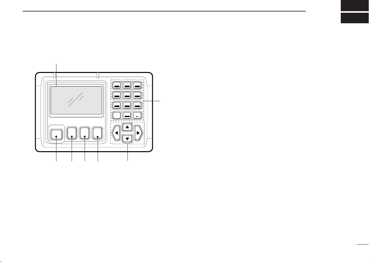
■ Front panel
q DISTRESS BUTTON
Push and hold for 5 sec. to make a distress call.
w CLEAR SWITCH [CLR]
➥ Push this key to cancel Call repeat.
➥ Push this key to cancel the menu.
e CALL SWITCH [CALL]
➥ Push this key to call up a subject menu screen.
➥ Push the key to return to the start screen.
r ENTER [ENT]
➥ Enters the selected subject and advances the item to in-
dicate the contents.
➥ Push this key to determine the data.
t UP/DOWN/LEFT/RIGHT SWITCHES [Y]/[Z]/[ΩΩ]/[≈≈]
➥ Push [Y]/[Z] to select the menu contents in the selected
item.
➥ Push [Y]/[Z] to adjust brightness and contrast.
➥ Push [Ω]/[≈] to move the cursor position.
y KEYPAD
➥ Input the corresponding number or letters when re-
quired.
➥ Other functions are as follows;
[A/a]–Push this key to toggle between capital letters,
small letters or numerals. ‘A; capital letter’ or ‘a;
small letter’ appears in the upper right of the display,
depending on selection.
[BS]–Backspace key.
u FUNCTION DISPLAY
During normal operation the display shows position and
UTC (or Local) time when a GPS receiver is connected.
This is updated each time new GPS data is received.
If no GPS receiver is connected, the position and UTC time
must be set in advance.
1
Page 6
1
-VHF DSC CONTROLLER-
CH 70 WATCHING
GPS:UTC4:45
Lat4559'N
Lon13444'E
w
q
e
PANEL DESCRIPTION
NOTE: If GPS data is interrupted for 30 sec. the “GPS” indication disappears. The terminal unit retains the most recent
data in such cases.
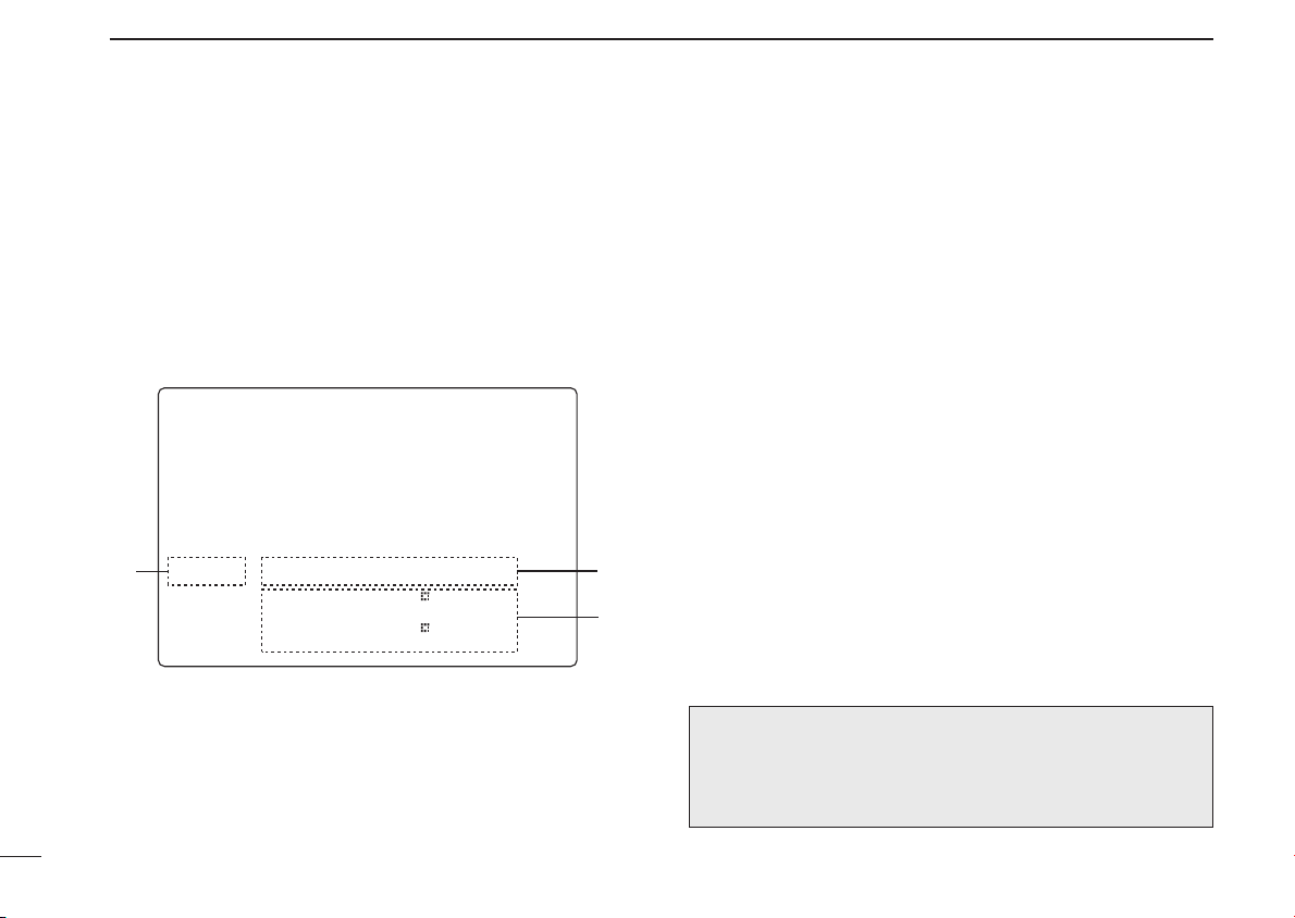
■ Function display
q GPS INDICATOR
➥ “GPS” appears while GPS receiver is connected.
2
➥ “GPS’ disappears when no GPS receiver is connected.
➥ “MNL’ appears when the time data and position data are
input manually.
w TIME ZONE INDICATOR
➥ “Local” appears when the offset time data in the ‘Set-up’
menu is entered.
➥ “No time data’ appears when no GPS receiver is con-
nected and no time data is input manually.
e POSITION INDICATOR
➥ Shows the GPS position data.
• “??” may blink every 2 sec. instead of position data, when
the GPS position data is invalid. In such a case, the last
position data is held for up to 23.5 hours.
➥ Shows the manually input position data when no GPS re-
ceiver is connected. “MNL” appears instead of “GPS” at q.
• “??” may blink every 2 sec. instead of position data, 4
hours after the position data is input manually up until
23.5 hours have past.
➥ “No position data” appears when no GPS receiver is con-
nected and no position data is input manually.
NOTE: When no key operation is made for more than 5
minutes, the function display contents returns to the opening menu message as shown at left, automatically.
Page 7

■ Entring an MMSI
CALL PROCEDURE
2
An ID code of your ship must be
entered before using the unit for
the first time. Only 3 selectable
subjects appear when your ID
code has not been entered yet.
No distress call can be transmitted in the above condition.
<Select a subject>
Entry position/time
Received calls
≈Set up
D Entring an MMSI
q Push [CALL], then push [√]
to select ‘Set up’.
w Push [ENT], then push [Z]
several times to select
‘MMSI entry’, then push
[ENT] again.
e Enter the 9 (nine) digit ID
code.
r Push [POWER] on the con-
nected transceiver to turn the
power OFF.
t Push [POWER] to turn the
power ON again. All operating items/functions can be
selected and use from now
on.
<Select a subject>
Brightness
Contrast
MMSI check
≈MMSI entry
<CLR Exit / ENT OK>
<Entry a MMSI >
ID:(9digit)
_____________
Turn power OFF once,
then turn it ON again
3
Page 8

2
CALL PROCEDURE
■ Distress call/Simple operation
A distress call should be transmitted if, in the opinion of the
Master, the ship or a person is in distress and requires immediate assistance.
A distress call should include the ship’s position and time.
They are included automatically when a GPS receiver is connected. If no GPS is connected, input them, if possible.
NEVER: USE THE DISTRESS CALL WHEN
YOUR SHIP IS NOT IN AN EMERGENCY.
DISTRESS CALL CAN BE USED ONLY WHEN
IMMEDIATE HELP IS NEEDED.
q Confirm any distress call is
not being received.
w Lift up the switch cover. Push
and hold the [DISTRESS]
button for 5 sec. to transmit
the distress call.
• A DSC channel (Ch 70) is automatically selected and the distress call is transmitted.
• If you have the time, select the
nature of the distress and contents.
• If no GPS is connected, your location and UTC time should be
input.
<Push and hold
[DISTRESS] for 5 sec>
Nature of distress:
Undesignated
GPS : UTC 15:22
12°34’N
123°45’W
phone frequency (Ch 16) automatically.
• The controller is still waiting on
Ch 70 for an acknowledgment
call.
r When receiving the acknowl-
edgment, reply to the connected station via the
Distress alert
Completed
Now waiting for
acknowledgment
transceiver’s microphone as
described on the page at
<CLR→Exit>
right.
NOTE:
• Distress alert (simple operation) contains (default);
Kind of distress: Undesignated distress
Position data: According to the displayed information.
- GPS or manual input position data held for 23.5 hrs.
• Distress call repeats every 3.5–4.5 min., until receiving an ‘ac-
knowledgement’
• Beep (Pi,Pi) sounds with the max. volume every 1 sec.
• Push [DISTRESS] button to transmit a renewed distress call, if de-
sired.
• Push [CLR] to cancel the ‘Call repeat’ mode.
The ‘cancel acknowledgement’ is automatically transmitted
when the [CLR] key is pushed.
e After transmitting the call, the transceiver is set to the
4
Page 9

CALL PROCEDURE
2
■ Distress call/Regular operation
Transmit a distress call after selecting the ‘Distress setting’.
NEVER: USE THE DISTRESS CALL WHEN
YOUR SHIP IS NOT IN AN EMERGENCY.
DISTRESS CALL CAN BE USED ONLY WHEN
IMMEDIATE HELP IS NEEDED.
q Push [CALL], then push [√]
several times to select ‘Distress setting’.
w Push [ENT] to select <Select
a nature>. Push [√] several
times to select the desired
nature, then push [ENT].
• Push [CLR] to Exit the menu.
e Confirm the location data,
then push [ENT] to confirm the time data.
r Confirm the UTC time, then push [ENT] to confirm the time
data.
• If no GPS is connected, your location and UTC time should be
input.
<Select a subject>
Entry position/time
Individual call
Group call
All ships call
Received calls
≈Distress setting
t Lift up the [DISTRESS] switch cover. Push and hold the
button for 5 sec. to transmit
the distress call.
• A DSC channel (Ch 70) is automatically selected and the distress call is transmitted.
• If no GPS is connected, your location and UTC time should be
input.
y After transmitting the call, the
transceiver is set to the voice
calling channel (Ch 16) automatically.
• The controller is still waiting for
an acknowledgment call on Ch
70.
u When receiving the acknowl-
edgment, reply to the connected station via the
transceiver’s microphone as
described on page 8.
<Select a nature>
Undesignated
Fire,Explosion
Flooding
Collision
Grounding
Capsizing
≈Sinking
Disable adrift
Abandoning ship
Piracy attack
Man overboard
EPIRB emission
<Push and hold
[DISTRESS] for 5 sec>
Nature of distress:
Abandoning ship
GPS : UTC 15:22
12.34’N
123.45’W
5
Page 10

2
CALL PROCEDURE
NOTE:
• ‘nature of distress’ will be valid for 10 min. until a distress
call transmits. After 10 min. it reverts to an undesignated distress.
• Distress call repeats every 3.5–4.5 min., until receiving an
‘acknowledgement’
• Beep (Pi,Pi) sounds with the max. volume every 1 sec. until
acknowledgement is received.
• Push clear to cancel a distress call prior to receiving and an
acknowledgement.
The ‘cancel acknowledgement’ is automatically transmitted when
the [CLR] key is pushed.
■ Entry Position/Time
When no GPS receiver is connected, the ‘Entry
Position/Time’ appears at the top of the subject menu.
q Push [CALL], then push [√] to select ‘Entry Position/Time’.
w Push [ENT], then enter the latitude data with the key pad.
e Push [Y]/[Z] to select N; north latitude or S; south latitude,
then push [ENT].
• Push [Ω]/[≈] to move the cur-
sor then push [Y]/[Z] to correct
the data
• Push [CLR] to Exit the menu.
• Push [A/a], the push [ENT] to
enter ‘Null data’.
r Enter the longitude data with
the key pad.
t Push [Y]/[Z] to select E;
east longitude or W; west
longitude, then push [ENT].
• Push [Ω]/[≈] to move the cursor then push [Y]/[Z] to correct
the data
• Push [CLR] to Exit the menu.
• Push [A/a], the push [ENT] to
enter ‘Null data’.
<Input a position>
Latitude
°’N
Longitude
°’E
<A/a Null data>
<CLR Exit / ENT OK>
<Input a Time>
UTC :
<A/a Null data>
<CLR Exit / ENT OK>
6
Page 11

CALL PROCEDURE
2
y Push UTC time with the keypad.
• Push [Ω]/[≈] to move the cursor then push [Y]/[Z] to correct the
data
• Push [CLR] to Exit the menu.
• Push [A/a], then push [ENT] to enter ‘Null data’.
■ Distress call to ships
General DSC calls may be used for communications after the
Distress call, e.g. you want to change the operating mode,
frequency, etc.
■ Individual call
D Individual call to the coast station
q Push [CALL], then push [√] several times to select ‘Indi-
vidual call’ then push [ENT].
w Push [√] several times to select the coast station ID ad-
dress. Then push [ENT].
(See page 18 for adding an address.)
e Select the coast station ID.
e Push [CALL] and [ENT] simultaneously to transmit an Indi-
vidual call.
• Push [CLR] to stop the call.
r ‘RCV Individual call—From: Coast stn’, appears on the
screen.
t Push [ENT] to transfer the instructed traffic channel
transceiver.
* Traffic channel is determined by the coast station automatically.
* to the
D Individual call to other ships
q Push [CALL], then push [√] several times to select ‘Indi-
vidual call’ then push [ENT].
w Select ‘manual entry’ to enter
9 digit ID or push [√] to select the desired ID address.
Then push [ENT].
• ‘Select a traffic CH’ screen appears.
e Push [Y]/[Z] to select your
desired traffic channel from
the list. Then push [ENT].
r Push [CALL] and [ENT] si-
multaneously to transmit an
Individual call.
• Push [CLR] to stop the call.
<Select address ID>
≈Manual entry
DS-100 SN10
DS100 SN2
DS100 SN3
<CLR Exit / ENT OK>
<Input address ID>
ID:(9digit)
<CLR Exit / ENT OK>
7
Page 12

2
CALL PROCEDURE
■ Group call
q Push [CALL], then push [√]
one or more times to select
‘Group call’, then push
[ENT].
w Select ‘manual entry’ to enter
8 digit ID or push [√] to select the desired ID address.
Then push [ENT].
• ‘Select a traffic CH’ screen appears.
e Push [Y]/[Z] to select your
desired traffic channel from
the list. Then push [ENT].
r Push [CALL] and [ENT] si-
multaneously to transmit an
Individual call.
• Push [CLR] to stop the call.
<Select a group>
≈Manual entry
ICOM
<CLR Exit / ENT OK>
<Input an address>
ID:(8digit)
0
<CLR Exit / ENT OK>
■ All ships call
q Push [CALL], then push [√]
one or more times to select
‘All ships call’, then push
[ENT].
w Select the desired category,
then push [ENT].
e To select desired traffic
channel push [BS] twice and
enter channel number.*
r Push [CALL] and [ENT] simultaneously to transmit an All
ships call.
• Push [CLR] to stop the call.
* Traffic channel automatically defaults to channel 16.
<Select a category>
Safety
≈Urgency
<CLR Exit / ENT OK>
8
Page 13

CALL PROCEDURE
2
D When no acknowledgement is received
When no acknowledgement is received the unit will beep
every one second. In this case, the controller automatically
transmits the distress call again every 3.5 to 4.5 minutes.
• A distress relay call may be received after several minutes from another ship if acknowledgement cannot be received from a coast station directly.
CAUTION: DO NOT push [CLR] while waiting for an acknowledgement, otherwise the distress call repeat will be
cancelled, and a distress acknowledgement is automatically transmitted with your own MMSI.
Use the [CLR] key only when you want to cancel repeated
transmission.
D After receiving an acknowledgement call
The following should be commenced with your voice transmission after receiving a distress acknowledgement from a
coast station (or another ship).
• “MAY DAY”
• “This is .........(your ship name)”
• The 9-digit identity AND the call sign (or other identification of the ship).
• The ship’s position if the DSC distress does not include it.
• The nature of the distress and assistance required.
• Any other information which might facilitate the rescue.
9
Page 14

3
WHEN RECEIVING A DSC CALL
■ When receiving a
Distress call
When receiving a distress call,
an alarm (Pi-po) sounds with
max. AF level continuously. And
at the same time, the transceiver’s (such as ICM401EURO or IC-M503)
operating channel changes to
CH 16 automatically.
• Push [CLR] to cancel the
alarm.
• Monitor the communication between the calling ship and
a coast station. When no communication is made, contact the ship using voice transmission on CH 16.
—RCV Distress call—
Distress ID:
23456789
Distress time & pos
Time: UTC 12:34
Pos.: Lat 12°34’N
Lon 123°45’W
10
Page 15

WHEN RECEIVING A DSC CALL
3
D When receiving an individual call
When receiving an individual
call, an alarm (Pi-pi) sounds.
• Push [ENT], then the operating channel changes to
the designated channel.
• Push [CLR] to record the
received information, then
the screen goes back to default.
• The calling station transmits via voice on the designated
channel.
—RCV Individual call—
From: JOHN
<CLR➝Exit/ ENT➝OK>
• When the individual ACK function is available
When the individual acknowledgement function is available
on your controller, push [ENT]
to turn to the <Select to comply> screen.
• Select ‘Able to comply’ or
‘Unable to comply’.
• Emergency alarm (or continuous beeps depending
on the category) sounds until pushing [CLR].
<Select to comply>
≈Able to comply
Unable to comply
<CLR➝Exit/ ENT➝OK>
11
Page 16

3
WHEN RECEIVING A DSC CALL
D When receiving an All ships call
• When receiving a Routine or
Safety all ships call, an alarm
(Pi-pi) sounds.
• When you receive a distress
or Urgency all ships call, an
alarm (Pi-po) sounds with
max. AF level continuously.
• Push [CLR] to cancel the
alarm.
• Push [ENT], then the operating channel changes to the received traffic channel automatically.
• Push [CLR] to record the received information, then the
screen goes back to default.
You must monitor the traffic frequency until you can judge
from the call that your action has been effective and/or assistance is unnecessary.
—RCV All ships call—
From: 23456789
Category: Routine
<CLR➝Exit/ ENT➝OK>
D When receiving a Position request
When receiving a Position request call, an alarm (Pi-pi)
sounds.
• Push [ENT] to transmit your
—RCV Pos request—
From: JOHN
own ships longitude and latitude information.
• Push [CLR] to record the
received information, then
To reply, push ENT
<CLR➝Exit/ ENT➝OK>
the screen goes back to default.
D When receiving a Position reply
When receiving a Position reply,
an alarm (Pi-pi) sounds.
• Push [CLR] to record the
received information, then
the screen goes back to default.
—RCV Pos reply—
From: Beck
Pos.: Lat 12°34’N
Lon 123°45’W
<CLR➝Exit>
12
Page 17

WHEN RECEIVING A DSC CALL
3
D When receiving a Distress ACK
When receiving a distress acknowledgement, an alarm (Pipo) sounds with max. AF level
continuously. And at the same
time, the transceiver’s (ICM503/M401EURO) operating
—RCV Distress ACK—
From: Tokyo guard
Distress ID:
Mr.Bean
channel changes to CH 16 automatically.
<CLR➝Exit/ ENT➝OK>
• Push [CLR] to cancel the
alarm.
• You must monitor CH 16 until you can judge from the call
that your assistance is unnecessary.
D When receiving a Distress Relay ACK
When receiving a Distress
Relay acknowledgement, an
alarm (Pi-po) sounds with max.
AF level continuously. And at
the same time, the transceiver’s
(IC-M503/M401EURO) operating channel changes to CH 16
automatically.
• Push [CLR] to cancel the
alarm.
• You must monitor CH 16 until you can judge from the call
that your assistance is unnecessary.
—RCV Distress RLY ACK—
From: Tokyo guard
Distress ID:
987654321
<CLR➝Exit/ ENT➝OK>
D When receiving a group call
When receiving a Group call,
an alarm (Pi-pi) sounds.
• Push [ENT], then the operating channel changes to
the designated channel.
• Push [CLR] to record the
received information, then
the screen goes back to default.
• The calling station transmits
via voice on the designated channel.
—RCV Group call—
From: DS-100 SN3
Group:Icom Inc
<CLR➝Exit/ ENT➝OK>
13
Page 18

3
3
WHEN RECEIVING A DSC CALL
■ Received message (RCV MSG)
When receiving a DSC call, the received format is specified
and its contents are memorized into the received message
(RCV MSG) memory. Distress calls (including other calls with
distress category) are stored separately from other calls.
Up to 20 distress calls can be
memorized and up 20 other categories of calls can be memorized. However, the distress
calls are saved until being
erased, while other calls are
erased when the power is
turned OFF.
<Select a subject>
Entry Position/Time
Individual call
Group call
All ships call
≈Received calls
Distress setting
D Distress message
q Push [CALL], then push [√]
one or more times to select
‘Received calls’, then push
[ENT].
w Select a ‘Distress message’,
then push [ENT].
e Select a desired message,
then push [ENT].
• Push [Y] or [Z] to scroll the
message.
• Push [A/a], then push [1] to
clear the message.
NOTE: The message number
that has not been read yet
blinks, e.g.
.
<Select a message>
≈Distress message
Other message
<CLR Exit / ENT OK>
<Select a message>
≈1:Distress 12:21
2:Distress 11:21
3:Distress 10:21
4:Distress 09:21
<CLR Exit / ENT OK>
<Message contents>
Distress ID:
2345678
Piracy attack
Distress time & Pos
Time: UTC 12:34
Pos.: Lat 12°34’N
Lon 123°45’W
<A/a Data clear>
14
Page 19

D Other messages
WHEN RECEIVING A DSC CALL
3
• Individual call
q Push [CALL], then push [√]
several times to select ‘Received calls’, then push
[ENT].
w Select ‘Other message’, then
push [ENT].
e Select ‘Individual call’, then
push [ENT].
• Push [Y] or [Z] to scroll the
message.
• Push [A/a] to clear the message.
<Select a message>
1:Individual ACK
≈2:Individual call
3:Group call
4:All ships call
5:Distress
6:Distress relay
7:Distress RLY ACK
8:Distress ACK
<CLR Exit / ENT OK>
<Message contents>
Routine to Individual
From: DS-100 SN3
F3E/G3E simplex
CH88
No information
<A/a Data clear>
• Group call
q Push [CALL], then push [√]
several times to select ‘Received calls’, then push
[ENT].
w Select ‘Other message’, then
push [ENT].
e Select ‘Group call’, then
push [ENT].
• Push [Y] or [Z] to scroll the
message.
• Push [A/a] to clear the message.
<Select a message>
1:Individual ACK
2:Individual call
≈3:Group call
4:All ships call
5:Distress
6:Distress relay
7:Distress RLY ACK
8:Distress ACK
<CLR Exit / ENT OK>
<Message contents>
Routine to group
From: Phil Collins
F3E/G3E simplex
CH78
No information
15
Page 20

3
WHEN RECEIVING A DSC CALL
• All ships
q Push [CALL], then push [√]
several times to select ‘Received calls’, then push
[ENT].
w Select ‘Other message’, then
push [ENT].
e Select ‘All ships call’, then
push [ENT].
• Push [Y] or [Z] to scroll the
message.
• Push [A/a] to clear the message.
• Distress
q Push [CALL], then push [√]
several times to select ‘Received calls’, then push
[ENT].
w Select ‘Other message’, then
push [ENT].
e Select ‘Distress’, then push
[ENT].
• Push [Y] or [Z] to scroll the
message.
• Push [A/a] to clear the message.
<Message contents>
Urgency to All ships
From: DS-100 SN3
F3E/G3E simplex
CH 14
<A/a Data clear>
<Message contents>
Routine to group
From: Phil Collins
F3E/G3E Simplex
CH88
No Information
<A/a Data clear>
• Distress relay
q Push [CALL], then push [√]
several times to select ‘Received calls’, then push
[ENT].
w Select ‘Other message’, then
push [ENT].
e Select ‘Distress relay’, then
push [ENT].
• Push [Y] or [Z] to scroll the
message.
• Push [A/a] to clear the message.
<Message contents>
Distress relay
From: Phil Collins
Distress ID:
2345678
To all ships
Fire,Explosion
Distress Time & Pos
Time: UTC 12:34
Pos.: Lat 12°34’N
Lon 123°45’W
<A/a Data clear>
16
Page 21

WHEN RECEIVING A DSC CALL
3
• Distress relay acknowledgement
q Push [CALL], then push [√]
several times to select ‘Received calls’, then push
[ENT].
w Select ‘Other message’, then
push [ENT].
e Select ‘Distress RLY ACK’,
then push [ENT].
• Push [Y] or [Z] to scroll the
message.
• Push [A/a] to clear the message.
* Please note:
Commercial vessels can only
transmit distress relay messages.
<Select a message>
1:Individual ACK
2:Individual call
3:Group call
4:All ships call
5:Distress
6:Distress relay
≈7:Distress RLY ACK
8:Distress ACK
<CLR Exit / ENT OK>
<Message contents>
Distress RLY ACK
From: Mr.Comfort
Distress ID:
Mrs.John
Fire,Explosion
Distress Time & Pos
Time: UTC 12:34
Pos.: Lat 12°34’N
Lon 123°45’W
.• Distress acknowledgement
q Push [CALL], then push [√]
several times to select ‘Received calls’, then push
[ENT].
w Select ‘Other message’, then
push [ENT].
e Select ‘Distress ACK’, then
push [ENT].
• Push [Y] or [Z] to scroll the
message.
• Push [A/a] to clear the message.
<Select a message>
1:Individual ACK
2:Individual call
3:Group call
4:All ships call
5:Distress
6:Distress relay
7:Distress RLY ACK
≈8:Distress ACK
<CLR Exit / ENT OK>
<Message contents>
Distress ACK
From: Mr.Fortune
Distress ID:
Mrs.John
Fire,Explosion
Distress Time & Pos
Time: UTC 12:34
Pos.: Lat 12°34’N
Lon 123°45’W
<A/a Data clear>
<A/a Data clear>
17
Page 22

4
SET-UP
■ Select ‘Set-up’
The following setting/operations are available in ‘Set-up’
menu.
• Address ID
• Offset time
• Brightness
• Contrast
• MMSI check
q Push [CALL], then push [√]
several times to select ‘Setup’, then push [ENT].
• ‘Set-up’ menu appears on
the screen.
w Push [CLR] to exit the Set-up
menu.
<Select a subject>
Individual ACK
Group call
All ships call
Received calls
Distress setting
≈Set-up
<Select a subject>
≈Address ID
Offset time
Brightness
Contrast
MMSI CHECK
<CLR➝Exit / ENT➝OK>
■ Address ID
A total of 70 address ID’s can be programmed as “Address
ID” (for ships and coast stations) and “Group ID” (for group
station).
• Adding an address ID
q Push [∫]/[√] several times to
select ‘Add an address ID’,
then push [ENT].
w Push the numeral keys to
input an address ID code,
then push [ENT].
• When a wrong number is input,
push [CLR], then enter the
number again.
e Enter the desired name for
the ID code, then push
[ENT].
• Push [A/a] several times to toggle capital letters, small letters
and numerals.
• Push the corresponding key
one or more times to input the desired character.
• Push [BS] to erase the character.
• Push [Ω] to reverse the cursor position; [≈] to forward the cursor
position.
r Push [CLR] to exit the screen.
<Select a subject>
≈Add an address ID
Delete address ID
Add a group ID
Delete a group ID
<CLR➝Exit / ENT➝OK>
<Add an address ID>a*
ID:(9digit)
Name:(15characters)
<CLR➝Exit / ENT➝OK>
18
Page 23

SET-UP
4
• Delete address ID
q Push [√] to select ‘Delete
address ID’, then push
[ENT].
w Push [∫]/[√] several times to
select a desired address ID
that you want to delete, then
push [ENT].
• Address ID and name is displayed on the screen.
e Push [ENT] to delete the ad-
dress ID.
• Push [CLR] to exit the
screen.
r Push [CLR] to exit the menu.
<Delete address ID>
≈DS-100 SN10
DS-100 SN2
DS-100 SN3
DS-100 SN4
<CLR➝Exit/ENT➝OK>
<Delete this ID>
ID:(9digit)
2673500100
Name:(15characters)
DS-100 SN10
<CLR➝Exit / ENT➝OK>
• Add a group ID
q Push [∫]/[√] several times to
select ‘Add a group ID’, then
push [ENT].
w Push numeral keys to input
an address ID code, then
<Add a group ID> a*
ID:(8digit)
0
Name:(15characters)
push [ENT].
• When a wrong number is input,
push [CLR], then enter the
number again.
<CLR➝Exit / ENT➝OK>
e Enter the desired name for the ID code, then push [ENT].
• Push [A/a] several times to toggle capital letters, small letters and
numerals.
• Push the corresponding key one or more times to input the desired character.
• Push [BS] to erase the character.
• Push [Ω] to reverse the cursor position; [≈] or forward the cur-
sor position.
r Push [CLR] to exit the screen.
• Delete a group ID
q Push [√] to select ‘Delete a group ID’, then push [ENT].
w Push [∫]/[√] several times to select a desired address ID
that you want to delete, then push [ENT].
• Address ID and name is displayed on the screen.
e Push [ENT] to delete the address ID.
• Push [CLR] to exit the screen.
r Push [CLR] to exit the menu.
19
Page 24

4
SET-UP
■ Offset time
Local time can be used when
the GPS position data is valid
and offset time is input.
q Push [CALL], then push [√]
one or more times to select
‘Set-up’, then push [ENT].
w Select ‘Offset time’, then
push [ENT].
e Push “0; –” or “1; space”, then input the time differences.
r Push [ENT] to determine the time or push [CLR] to exit the
Set-up menu.
<Offset time>
—09:30
<CLR➝Exit / ENT➝OK>
■ Brightness
• Adjusting the brightness
q Push [CALL], then push [√] one or more times to select
‘Set-up’, then push [ENT].
w Select ‘Brightness’, then push [ENT].
e Push [Y] or [Z] one or more times (or numeral keys in-
stead) to adjust the brightness.
• Brightness level indication; 1 (dark) to 8 (bright)
r Push [ENT] to determine the brightness or push [CLR] to
exit the Set-up menu.
■ Contrast
• Adjusting the contrast
q Push [CALL], then push [√] one or more times to select
‘Set-up’, then push [ENT].
w Select ‘Contrast’, then push [ENT].
e Push [Y] or [Z] one or more times (or numeral keys in-
stead) to adjust the contrast.
• Contrast level indication; 1 (low) to 8 (high)
r Push [ENT] to determine the brightness or push [CLR] to
exit the Set-up menu.
■ MMSI check
Your ID code can be displayed via the set-up menu.
• Check your ID
q Push [CALL], then push [√]
one or more times to select
‘Set-up’, then push [ENT].
w Select ‘MMSI check’, then
push [ENT].
e Your ID code shows on the
display.
r Push [CLR] to exit the Set-up
menu.
<MMSI check>
267350012
<CLR Exit>
20
Page 25

CONNECTIONS AND INSTALLATION
■ Connection diagram (Connection exsample with IC-M503)
5
13.8V DC
i
GND
IC-M503
(or IC-M401EURO)
NOTE: Binding the GPS cable, GPS connector, clone re-
ceptacle, antenna connector with water-resistant tape, increases the waterproofing of the controller.
e
u
y
r
w
t
DS-100 (#02)
q
21
Page 26

5
CONNECTION AND INSTALLATION
■ Rear panel description
q CONNECTION CABLE
Connects to the IC-M503 (or IC-M401EURO) rear DSC
controller receptacle.
w RECEIVE ANTENNA CONNECTOR
Connects a marine VHF receiving antenna with a PL-259
plug for emergency frequency signal receiving.
• Receiving frequency : 156.525 MHz
• Keep the emergency frequency signal receiving antenna
away from the marine VHF antenna to avoid interference
from the emitted RF signal.
e CLONE RECEPTACLE
For dealer use only.
r GPS RECEIVER CONNECTOR
Connects a GPS receiver (NMEA0183 ver.2.0) for sending
position data without manual input.
t EXTERNAL MICROPHONE CONNECTOR (IC-M503)*
Connects to the optional HM-134
PHONE
.
• Intercom function is available.
REMOTE-CONTROL MICRO
CAUTION: NEVER connect another microphone such
as the HM-127, etc. It may cause damage to the transceiver.
y ANTENNA CONNECTOR (IC-M503)*
Connects a marine VHF antenna with a PL-259 connector
to the transceiver.
u EXTERNAL SPEAKER RECEPTACLE (IC-M503)*
Connects to an external speaker.
i DC POWER CONNECTOR (IC-M503)*
Connects the DC power cable supplied with IC-M503 (or
IC-M401EURO), from this connector to an external 12 V
DC power source.
*Refer to the IC-M503 (or IC-M401EURO) instruction manual.
■ Supplied accessories
q Knob bolt (2040 knob bolt) ............................................. 2
w Mounting bracket (2345 Mobile bracket) ......................... 1
e Spring washers (M 5 ) .................................................... 2
-
r Self-tapping screws (A05 x 20)........................................ 2
t Flat washers (M 5)........................................................... 2
y Label (2349 CAUTION seal-R)........................................ 1
22
Page 27

CONNECTION AND INSTALLATION
5
■ Mounting
The universal mounting bracket supplied with your controller
allows dashboard or overhead mounting. Please read the following instructions carefully.
• Mount the controller securely with bolts and nuts or it may
come loose as a result of wave shocks or vibration.
• Mount the controller so that the face of the controller is at
90 degrees to your line of sight when operating it.
CAUTION!
KEEP the controller at least 1 m away from your ship’s mag-
netic navigation compass.
CHECK the installation angle; the function display may not
be easy-to-read at some angles.
• OVERHEAD MOUNTING
• DASHBOARD MOUNTING (with optional MB-75):
For mounting the DS-100 to a dashboard panel.
23
Page 28

6
.162025
VHF MARINE CHANNEL LIST
ï International channels
Frequency (MHz)
CH
Transmit
156.100 160.700
02
156.150 160.750
156.200 160.800
04
156.250 160.850
156.300 156.300
06
156.350 160.950
07
156.400 156.400
08
156.450 156.450
09
156.500 156.500
10 156.575
Receive
Frequency (MHz)
CH
Transmit
156.550 156.550156.050 160.650
11
156.600 156.600
12
156.650 156.650
13
156.700 156.700
14
156.750 156.750
15
156.800 156.800
16
156.850 156.850
17
156.900 161.500
18
156.950 161.550
19
157.000 161.600
20
Receive
Frequency (MHz)
CH
Transmit
157.050 161.650
21
157.100 161.700
22
157.150 161.750
23
157.200 161.800
24
157.250 161.850
25
157.300 161.900
26
157.350 161.950
27
157.400 162.000
28
156.025 160.625
60
156.075 160.675
61
Receive
Frequency (MHz)
CH
Transmit
156.125 160.725
62
156.175 160.775
63
156.225 160.825
64
156.275 160.875
65
156.325 160.925
66
156.375 156.375
67
156.42501156.425
68
156.47503156.475
69
156.52505156.525
70
156.575
71
Receive
Frequency (MHz)
CH
Transmit
156.625 156.625
72
156.675 156.675
73
156.725 156.725
74
156.775 156.775
75
156.825 156.825
76
156.875 156.875
77
156.925 161.525
78
156.975 161.575
79
157.025 161.625
80
157.075 161.675
81
Receive
Frequency (MHz)
CH
Transmit
157.125 161.725
82
157.175 161.775
83
157.225 161.825
84
157.275 161.875
157.375 161.975
85
86
157.325 162.025
157.375 157.375
87
157.425 157.425
88
Receive
161.925
24
Page 29

SPECIFICATIONS AND OPTIONS
7
■ Specifications
General
• Operating frequency : 156.525 MHz
• Mode : 16K0G2B
• Operating temperature range : –20°C to +60°C; –4°F to
+140°F
• Dimensions : 165(W) × 110(H) × 80(D) mm
(projections not included) 6.5 (W) × 4.33(H) × 3.15(D) in
• Weight : 1 Kg; 2.2 lb
• Receive system : Double-conversion
superheterodyne
• Intermediate frequencies : 1st 21.70 MHz
2nd 450 kHz
• Sensitivity : –10 dBµ
• Intermodulation rejection ratio : More than 68 dB
• Adjacent channel selectivity : More than 73 dB
• Spurious response rejection ratio : More than 73 dB
*Measurement methods according to EN 301 025
typ.
■ Options
MB-75 FLUSH MOUNT KIT
For mounting the DS-100 to a panel.
25
Page 30

8
DIMENSIONS
165.0
145.0
110.0
31.4 53.0
25.0
26
84.4
(Unit: mm)
Page 31

■ MB-75 FLUSH MOUNT KIT
MB-75 (OPTION)
9
The MB-75 is used to mount the DS-100 DSC CONTROLLER flush to a flat surface such as an instrument panel.
• Supplied accessories
Clamps . . . . . . . . . . . . . . . . . . . . . . . . . . . . . . . . . .1 set
• Instructions
q Using the template (p. 29), carefully cut a hole into the in-
strument panel (or wherever you plan to mount the controller) and slide the controller through the hole on the rear
panel.
w Attach the 2 supplied bolts on either side of the DS-100
(See next page.)
27
Page 32

9
MB-75
r Tighten the end bolts on the
clamps (rotate clockwise) so
that the clamps press firmly
against the inside of the instrument control panel.
28
e Attach the clamps on either side of the DS-100 as shown
below.
• Make sure that the clamps align parallel to the DS-100’s
body.
t Tighten the locking nuts (ro-
tate counterclockwise) so that
the DS-100 is securely
mounted in position as below.
y Connect the antenna and con-
trol cable, then return the instrument control panel to it’s
original place.
Page 33

149 (57/8)
TEMPLATE
• Cut on the inside of the line.
4–R11(7/16)
10
)
8
/
5
92 (3
Cut here
Unit: mm (inch)
29
Page 34

30
Page 35

DECLARATION
OF CONFORMITY
We Icom Inc. Japan
1-1-32 Kamiminami, Hirano-ku
Osaka 547-0003 Japan
Kind of equipment:
DSC CONTROLLER
This compliance is based on conformity with the following harmonised
standards, specifications or documents:
i)
EN 301 025-1 V1.1.2 (2000-08)
ii)
EN 301 025-2 V1.1.1 (2000-08)
iii)
EN 301 025-3 (2001-05)
iv) EN 60945 1997
v) EN 60950 1992
Type-designation: ds-100
Declare on our sole responsibility that this equipment complies the
essential requirements of the Radio and Telecommunications Terminal
Equipment Directive, 1999/5/EC, and that any applicable Essential Test
Suite measurements have been performed.
Version (where applicable):
˚
Signature
T. Maebayashi
General Manager
Authorized representative name
Icom (Europe) GmbH
Himmelgeister straße 100
D-40225 Düsseldorf
Place and date of issue
Düsseldorf 31st May 2001
0560
DOC
11
31
Page 36

Count on us!
‘
GER
‘
AUT
‘
GBR
‘
IRL
‘
FRA
SUI
‘
NED
‘
BEL
‘
LUX
‘
ESP
‘
POR
‘
ITA
‘
GRE
‘
SWE
‘
DEN
‘
FIN
< Intended Country of Use >
A-6066H-1EU-w
Printed in Japan
© 2001 Icom Inc.
#02
1-1-32 Kamiminami, Hirano-ku, Osaka 547-0003 Japan
 Loading...