

Page 1

Page 2
This
WORD
WARNING
shock may occur.
WARNING HIGH VOLTAGE! NEVER
WARNING HIGH VOLTAGE! NEVER
touch the antenna easily during transmission.
This may result in an electrical shock or burn.
re or damage the repeater.
apply more than 16 V DC, such as a
using or placing the repeater in areas
with temperatures below –30°C (–22°F) or above
putting anything on top of the repeater.
This will obstruct heat dissipation.
The heatsink will become hot
when operating the repeater continuously for long
Y-F121S/
series may damage the repeater.
This repeater is intended for use
The Icom America Systems logo is a trademark
of Icom, Inc.
The Icom America Systems logo is a trademark
of Icom, Inc.
Page 3

Thank you for purchasing this Icom America
VHF/UHF FM REPEATER.
With proper care, this product should provide
you years of trouble-free operation.
FEATURES
20 W continuous full duty cycle operation
This repeater looks as good as it performs.
Automatic battery backup system
A built-in backup system supports automatic
V DC) if the AC power supply fails.
Multiple CTCSS & DTCS tone memories
The following accessories are supplied with
AC power cable (OPC-510) ….............……… 1
Spare fuses (FGB 20A) ………..……….…… 1
Page 4
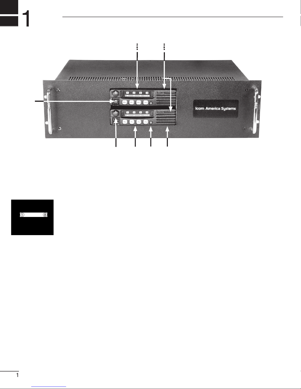
MICROPHONE/SPEAKER CONNECTOR
This 8-pin modular jack accepts the optional
AFO
monitor control)
VOLUME CONTROL [VOLUME]
Adjusts the audio output level.
POWER SWITCH [POWER]
INTERNAL SPEAKER
TRANSMITTER UNIT
RECEIVER UNIT
Page 5
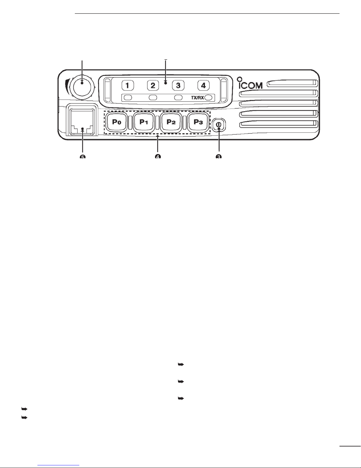
PANEL DESCRIPTION 1
AF VOLUME CONTROL KNOB
FUNCTION DISPLAY
The above functions depend on
POWER SWITCH [POWER]
DEALER-PROGRAMMABLE KEYS
MICROPHONE CONNECTOR
connect non-speci ed microphones.
The pin assignments may be different and
the transceiver may be damaged.
TX/RX INDICATOR
Lights red: while transmitting
Blinks orange (green and red blink simultaneous-
Green and red blink alternately: cloning error
ACTIVATED KEY INDICATOR (LP 0/1/2)
battery voltage is not too high.
Indicates the operating channel.
Blinks when receiving a signal during
All LEDs blink while entering the power
Page 6
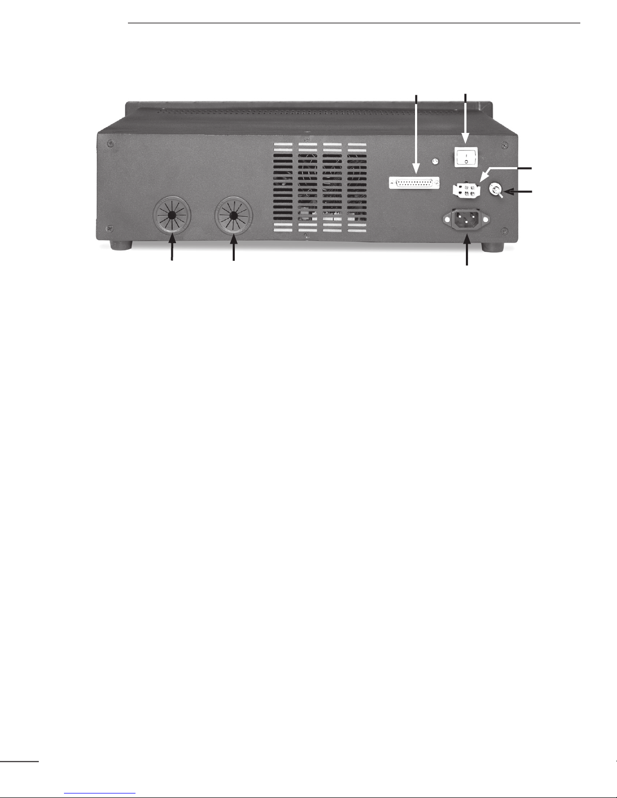
POWER SWITCH [POWER]
Toggles to turn the repeater power ON or
TRANSMIT ANTENNA CONNECTOR [TX/
TX•RX]
➥
➥
When installing an optional internal
ACCESSORY CONNECTOR [ACC]
RECEIVE ANTENNA CONNECTOR [RX]
When installing an internal duplexer
(supplied by third party), do not use this
AC POWER SOCKET [AC]
to prevent electric shocks, TVI, BCI and other
DC POWER INPUT TERMINALS [BATTERY
]
for DC power operation.
short the (+) line of the
PANEL DESCRIPTION 1
3
Page 7
Transmitter:
TX and RX to the transmit frequency
Set the CTCSS/CDCSS Tone
Set RF Power to High
TXData to F
Receiver:
frequency
Set the CTCSS/CDCSS Tone
Enable TX inhibit
Set RF Power to LOW2
Go to LMR>Common>Expert, set RX EXO to ON
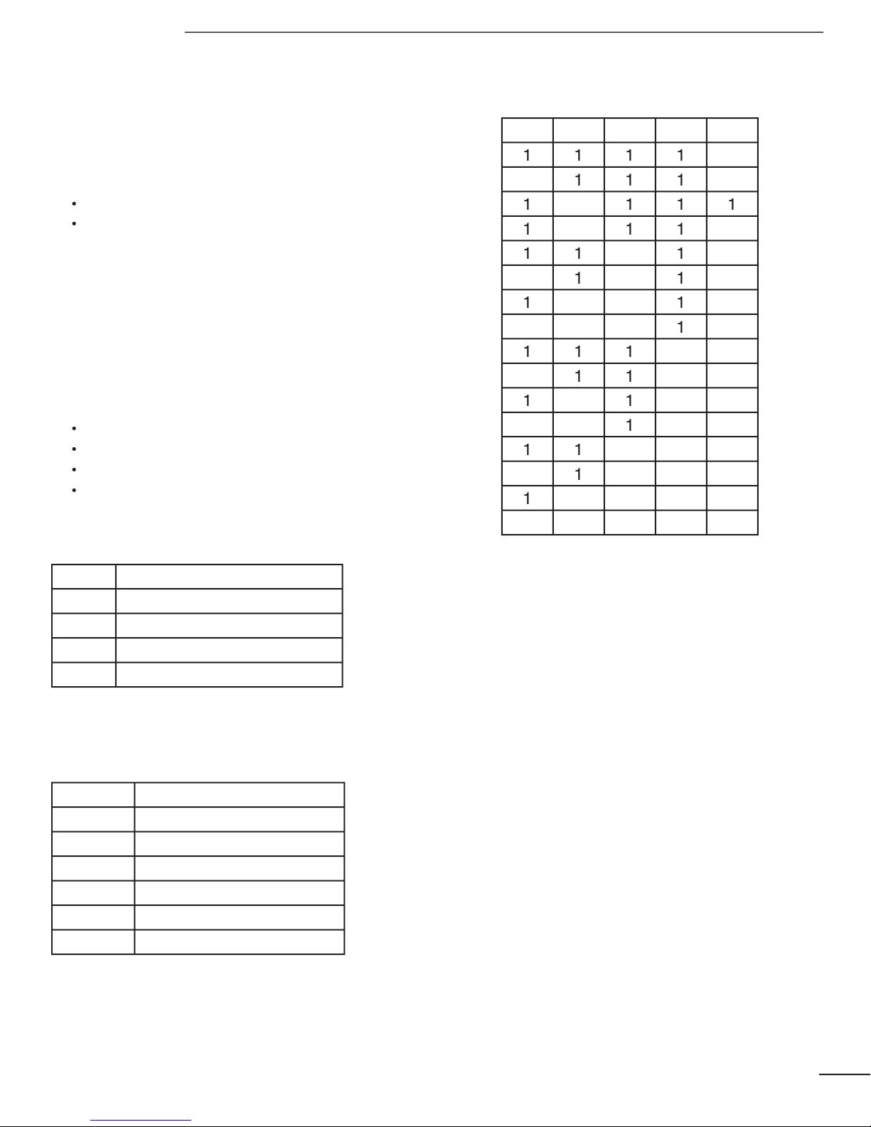
X1
Accessory Connector TX
X2
Accessory Connector RX
X3
X4
J6 Optional Connector RX
X5
J6 Optional Connector TX
JP2
JP3
Transmit On
JP4
JP5
JP6
JP7
JP8
Audio On
JUMPER SETTINGS
JP7
JP6
JP5
JP4
T sec.
3
3.5
4
4.5
PANEL DESCRIPTION 1
Page 8
Page 9

Page 10

Vcc TX
AFO TX
Audio Output, TX Unit
Transmit Audio, TX Unit
Transmit Data Input, TX Unit
Vcc RX
AFO RX
Audio Output, RX Unit
TXA RX
Transmit Audio, RX Unit
Transmit Data Input, RX Unit
PANEL DESCRIPTION 1
Page 11

After unpacking, immediately report any damage
to the delivering carrier or dealer. Keep the
transmission line should be a coaxial cable.
A duplexer is separately required when only
transmitting and receiving frequencies. Ask your
To prevent electrical shock, television interference
WARNING:
connect the
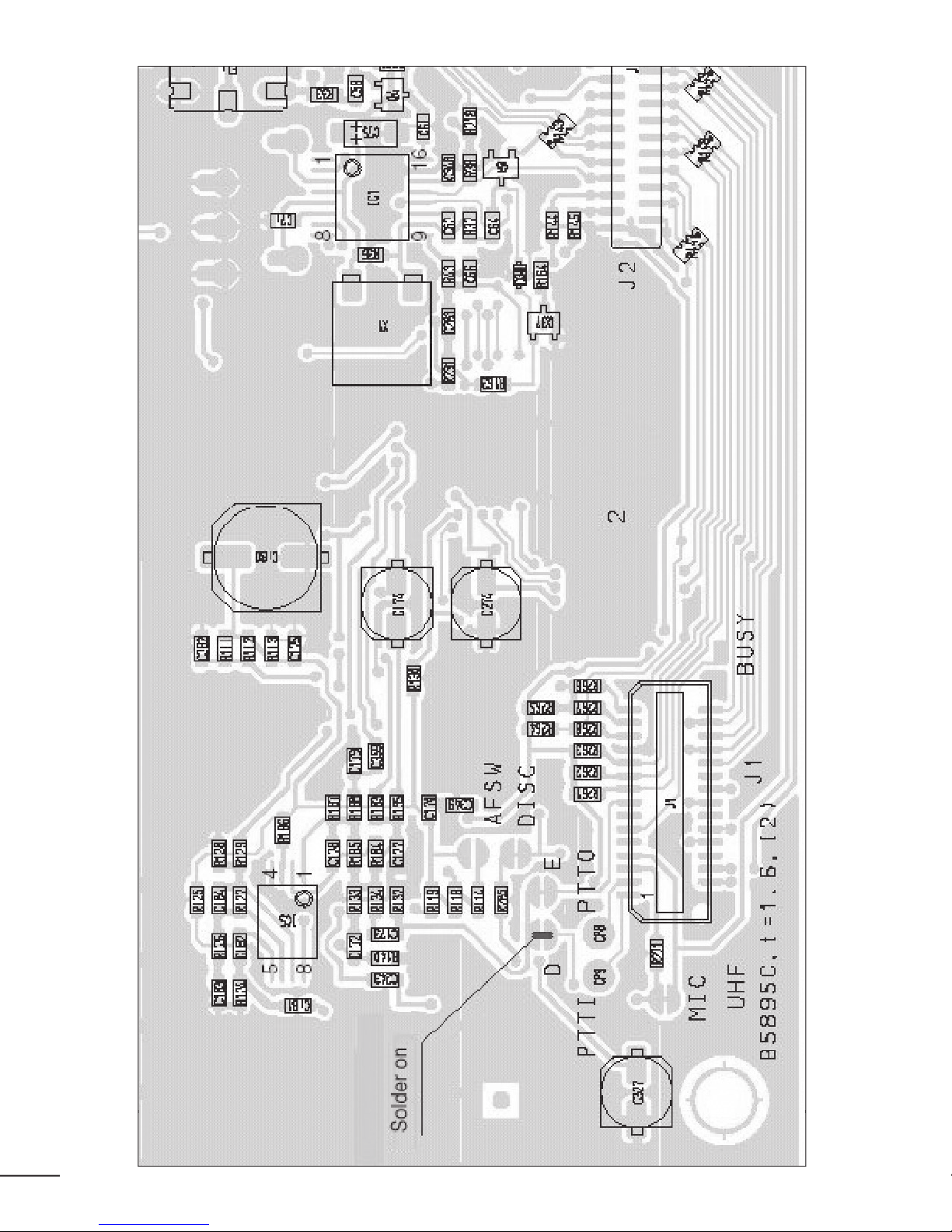
TYPE-N CONNECTOR INSTALLATION EXAMPLE
TYPE-N CONNECTOR INSTALLATION EXAMPLE
30 mm ≈ 9⁄8 in 10 mm ≈ 3⁄8 in 1–2 mm ≈ 1⁄16 in
Page 12

INSTALLATION AND CONNECTIONS 2
TX•RX antenna required
for installing an internal
duplexer.
Page 13

when connecting an AC power cable or a backup
The CY-F121S/221S series can operate with an
AC or DC power supply. If AC power is interrupted
when operating the repeater with an AC power
If turning the repeater OFF using the
turning it back ON. Otherwise, Logic circuits
Voltages greater than 16 V DC
will damage the repeater. Check the source
voltage before connecting the power cable.
the repeater. Lead-acid batteries should be
the connection and be sure both the positive
When connecting to the battery, connect the
the positive (red) terminal and negative
INSTALLATION AND CONNECTIONS 2
Page 14

the AC power cable
top cover.
Turn the repeater upside down.
Page 15

Turning power ON
Transmitting
Take the microphone off hook.
Wait for the channel to become clear.
voice level.
To maximize the readability of the transmitted
the microphone at a normal voice level.
Page 16

try to nd the source of the problem, and replace
the damaged fuse with a new, rated fuse.
WARNING:
the AC
the repeater. Otherwise, there is danger of
The left fuse, as pictured, is for repeater TX
The right fuse is for repeater RX”
Page 17

13.6 V DC nominal [50W]
(50W)
Max. Audio
Stand-by
0.3 A
(-22 °F to +140 °F)
480 (W) x 133 (H) x
364 (D) mm; 18.90 (W) x
480 (W) x 133 (H) x
364 (D) mm; 18.90 (W) x
25W/10W/2.5W
Variable reactance freq.
modulation
±2.5 kHz
±5.0 kHz
±5.0 ppm
6 dB/octave range from:
300 Hz to 2550 Hz [Narrow]
300 Hz to 3000 Hz [Wide]
deviation
40 dB
Double-conversion
superheterodyne system
st
0.25 µV at 12 dB SINAD
0.25 µV
Selectivity (typical)
40 dB
45 dB
4W typical at 10% distortion
with a 4Ω load
2-conductor 3.5 (d) mm
8
400.000-430.000 MHz*
440.000-490.000 MHz*
TX (25W)
(45W)
Max. Audio
Stand-by
0.3 A
480 (W) x 133 (H) x
364 (D) mm; 18.90 (W) x
480 (W) x 133 (H) x
364 (D) mm; 18.90 (W) x
8.6 kg; 18 lb
Transmitter
25W/10W/2.5W
Page 18

Variable reactance freq.
modulation
±2.5 kHz [Narrow]
±5.0 kHz [Wide]
±2.5 ppm
300 Hz to 2550 Hz [Narrow]
300 Hz to 3000 Hz [Wide]
3% typical at 1 kHz , 40%
deviation
40 dB
46 dB
st
0.25 µV at 12 dB SINAD
0.25 µV
Selectivity (typical)
40 dB
45 dB
4W typical at 10% distortion
with a 4Ω load
2-conductor 3.5 (d) mm
(
8
Page 19

Page 20

Page 21

7008
 Loading...