

Page 1
INSTRUCTIONS
q
PTT MICROPHONE ADAPTER
CT-23
PRECAUTIONS
R WARNING! NEVER connect a power adapter
to the CT-23 other than the specified one. This
may cause a fire or damage the CT-23.
CAUTION: NEVER connect a microphone
to the CT-23 other than the specified one.
Other microphones may have different pin
assignments, and could damage the CT-23 or
the microphone.
CAUTION: NEVER expose the CT-23 to rain,
snow or any liquids. This may damage the CT-23.
CAUTION: NEVER let metal, wire or other
objects protrude into the connector.
DO NOT use or place the CT-23 in areas with
temperatures below 0°C (32°F) or above
40°C (104°F).
DO NOT use harsh solvents such as Benzine
or alcohol to clean the CT-23. They will damage
the CT-23’s surfaces.
TIP:
Output audio from the CT-23 includes high
pitch tones that humans can hardly hear.
However, when you playback any recorded
audio while using the CT-23, it might be better
to not turn the volume too high.
Thank you for choosing this Icom product.
READ ALL INSTRUCTIONS carefully and
completely before using this product.
DISPOSAL
The crossed-out wheeled-bin
symbol on your product, literature,
or packaging reminds you that in
the European Union, all electrical
and electronic products, batteries,
and accumulators (rechargeable
batteries) must be taken to
designated collection locations at the end of
their working life. Do not dispose of these
products as unsorted municipal waste. Dispose
of them according to the laws in your area.
Icom is not responsible for the destruction,
damage to, or performance of any Icom or
non-Icom equipment, if the malfunction is
because of:
• Force majeure, including, but not limited to,
res, earthquakes, storms, oods, lightning,
other natural disasters, disturbances, riots,
war, or radioactive contamination.
• The use of Icom transceivers with any
equipment that is not manufactured or
approved by Icom.
FEATURES
m
Make Land Mobile microphones usable
for NXDN or dPMR system
When the SM-26/SM-25 (discontinued product)
stand microphone or the HM-152 hand microphone
is connected to a Remote Communicator (PC)
through the CT-23, you can make full use of the
microphone for your NXDN or dPMR system.
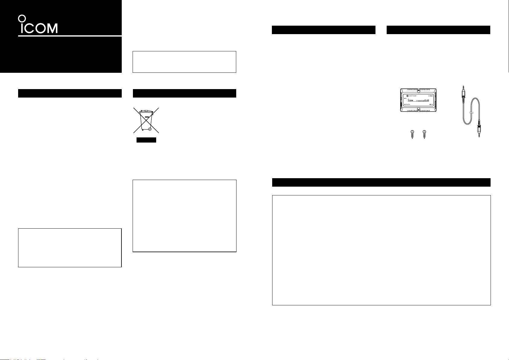
Item Qty.
q CT-23 ...................................................1
w Self tapping screws .............................. 2
e Audio cable .......................................... 1
SUPPLIED ITEMS
e
m POWER/TRANSMIT indicator
The CT-23 has a POWER/TRANSMIT indicator
on the top panel that indicates the operating
status.
m External switch is connectable
When an external switch is connected, you can
use it instead of the microphone’s [PTT] switch
or [MONITOR] switch.
w
m Easy connections
The CT-23 has 4 different types of connectors
for safe, easy connection.
FCC INFORMATION
For CLASS B UNINTENTIONAL RADIATORS
This equipment has been tested and found to comply with the limits for a Class B digital device,
pursuant to part 15 of the FCC Rules. These limits are designed to provide reasonable protection
against harmful interference in a residential installation. This equipment generates, uses and can
radiate radio frequency energy and, if not installed and used in accordance with the instructions,
may cause harmful interference to radio communications. However, there is no guarantee that
interference will not occur in a particular installation. If this equipment does cause harmful interference to radio or television reception, which can be determined by turning the equipment off and on,
the user is encouraged to try to correct the interference by one or more of the following measures:
• Reorient or relocate the receiving antenna.
• Increase the separation between the equipment and receiver.
• Connect the equipment into an outlet on a circuit different from that to which the receiver is connected.
• Consult the dealer or an experienced radio/TV technician for help.
Page 2
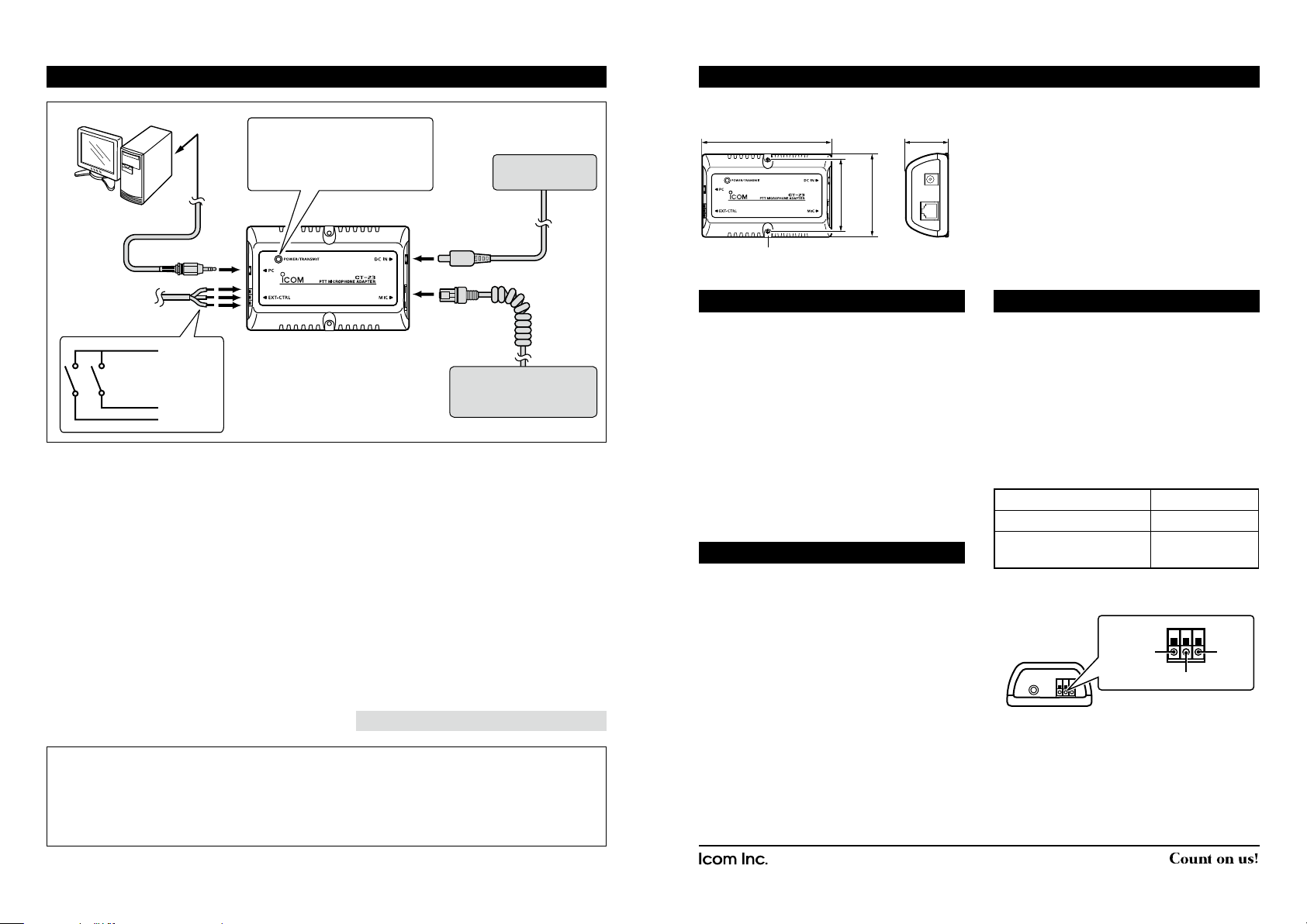
CONNECTIONS
* Purchase separately
SM-25 stand
microphone
HM-152 hand
microphone
DIMENSIONS AND INSTALLATION
to the microphone jack
POWER/TRANSMIT indicator
• Lights green when the power
is ON.
• Lights red while transmitting.
Remote
Communicator
(PC)
Supplied
to [PC]
audio cable
External switch
(user supplied)
GND
to [EXT-CTRL]
MONITOR
PTT
Connect the components to the CT-23 in the
following order:
q PC connection
Connect the microphone jack of the Remote
Communicator (PC) and [PC] using
the
supplied audio cable.
L The sound card of the PC must cover the
frequency response range of up to 20 kHz,
and have a sampling rate of 48 kHz, for the
PTT and Monitor* function.
w External switch connection
Connect an external switch (user supplied)
to the [EXT-CTRL] connector to remotely
control the PTT and Monitor* function.
Power adapter*
(BC-147S series)
to [DC IN]
rq
to [MIC]
ew
Microphone*
(SM-26, HM-152 or
SM-25 (discontinued))
e Microphone connection
Connect the SM-26, HM-152 or SM-25
(discontinued product) to [MIC].
You can use the following functions for your
NXDN or dPMR system.
• PTT function
• Monitor function
L Push the SM-26’s or SM-25’s [MONITOR]
switch, or take the HM-152 off the hook to
use the Monitor function.
r Power adapter connection
Connect one of the power adapters in the
BC-147S series that matches your power
voltage requirements.
• The POWER/TRANSMIT indicator lights green.
NOTE: Be sure to connect the power adapter last.
• Dimensions (approximate)
110.0 mm: 411⁄32 in. 36.1 mm: 113⁄32 in.
⁄32 in.
25
⁄32 in.
15
63.0 mm:
2
71.0 mm: 2
3.2 mm: 1⁄8 in. (mounting hole diameter)
INFORMATION
The following problems may occur, depending on
the PC’s sound card.
• If the [PTT] switch on the microphone, or the
external switch does not work, disable the
Filtering function of the sound card.
• If the CT-23 produces a disturbing noise,
disable the Mic boost of the sound card.
L For setting details, refer to the manual that
comes with the sound card or PC.
Mount the CT-23 onto a solid flat surface using
the 2 supplied screws through the mounting
holes.
EXT-CTRL CONNECTOR
The PTT or Monitor function is activated when
the PTT or Monitor control line is connected to
the ground.
L Information
• The monitor function is activated when the
MONITOR switch is closed.
• To control the monitor function from the external
switch, connect the specied microphone to the
CT-23.
Specications
Open terminal voltage 3.3 V DC
Terminal current when ON 1 mA (maximum)
SPECIFICATIONS
• Power Supply voltage: 12 V DC
(supplied from the power adapter)
Connector type
L Use wires with diameter of 0.4 to 1.2 mm:
1
⁄64 to 3⁄64 inches.
• Operating temp range: 0˚C to 40˚C
(32˚F to 104˚F)
• Relative humidity: 5% to 95%
• Weight (approximate): 93 g (3.28 oz)
GND
(Common)
• Length of the audio cable (approximate):
1 m (3.28 ft)
All stated specifications are subject to change without notice or obligation.
One-touch
terminal (3 poles)
PTT
MONITOR
TIP:
When the microphone is connected, you can transmit the microphone audio not only with the
microphone’s [PTT] switch, but also with the Remote Communicator’s [PTT] button, or the external switch.
To use the CT-23’s PTT/Monitor function, set the function to ON in the remote communicator
(IP100FS/RC-FS10).
See the remote communicator manual for details.
Icom, Icom Inc. and Icom logo are registered trademarks of Icom Incorporated (Japan) in Japan, the United States,
the United Kingdom, Germany, France, Spain, Russia, Australia, New Zealand, and/or other countries.
NXDN is a trademark of Icom Incorporated and JVC KENWOOD Corporation.
dPMR and the dPMR logo are trademarks of the dPMR MoU Association.
1-1-32 Kamiminami, Hirano-ku, Osaka 547-0003, Japan.
A-6775D-1EX-q Printed in Japan
© 2009–2017 Icom Inc.
 Loading...