

Page 1

PROGRAMMING
MANUAL
CLONING SOFTWARE
CS-F30G
Page 2

i
TABLE OF CONTENTS
FOREWORD
This manual explains in detail how to program each of the functions in the IC-F30GT/GS, IC-F31GT/GS, ICF40GT/GS and IC-F41GT/GS VHF AND UHF TRANSCEIVERS with the CS-F30G CLONING SOFTWARE. The CS-F30G
can be set up to meet any number of requirements of your customers, such as system conditions, channels,
frequencies, tones, etc.
FOREWORD . . . . . . . . . . . . . . . . . . . . . . . . . . . . i
TABLE OF CONTENTS . . . . . . . . . . . . . . . . . . . . i
1 PREPARATION . . . . . . . . . . . . . . . . . . . . 1
2 SCREEN DESCRIPTION . . . . . . . . . . . 2–5
2-1 MAIN SCREEN DESCRIPTION . . . . . . . 2–3
2-2 TREE VIEW SCREEN DESCRIPTION . . 4–5
3 COMMON SETTING . . . . . . . . . . . . . . 6–22
3-1 KEY & DISPLAYASSIGN . . . . . . . . . . 6–14
3-2 SET MODE . . . . . . . . . . . . . . . . . . . . . . . 15
3-3 COMMON 1 . . . . . . . . . . . . . . . . . . . . 16–17
3-4 COMMON 2 . . . . . . . . . . . . . . . . . . . . 18–19
3-5 EXPERT . . . . . . . . . . . . . . . . . . . . . . 20–21
3-6 CHARACTER EDITOR . . . . . . . . . . . . . . 22
4 MEMORY CHANNEL— LMR . . . . . . 23–28
5 MEMORY CHANNEL— PMR . . . . . . 29–39
6 DTMF AUTODIAL . . . . . . . . . . . . . . . 40–41
6-1 DTMF AUTODIAL . . . . . . . . . . . . . . . . . . 40
6-2 DTMF SETTING . . . . . . . . . . . . . . . . . . . 41
7 CONTINUOUS TONE . . . . . . . . . . . . . . . 42
8 SCAN LIST . . . . . . . . . . . . . . . . . . . 43–44
8-1 SCAN LIST . . . . . . . . . . . . . . . . . . . . . . . 43
8-2 SCAN SETTING . . . . . . . . . . . . . . . . . . . 44
9 2TONE . . . . . . . . . . . . . . . . . . . . . . . 45–48
9-1 RX CODE CHANNEL . . . . . . . . . . . . . 45–46
9-2 TX CODE . . . . . . . . . . . . . . . . . . . . . . . . 47
9-3 2TONE SETTING . . . . . . . . . . . . . . . . . . 48
10 5TONE . . . . . . . . . . . . . . . . . . . . . . 49–58
10-1 RX CODE CHANNEL . . . . . . . . . . . . 49–51
10-2 TX CODE CHANNEL . . . . . . . . . . . . 52–53
10-3 FORMAT . . . . . . . . . . . . . . . . . . . . . . . . 54
10-4 USER TONE . . . . . . . . . . . . . . . . . . . . . 55
10-5 5TONE SETTING . . . . . . . . . . . . . . . 56–58
11 PROGRAMMING for SmarTrunk II
operation . . . . . . . . . . . . . . . . . . . . 59–61
11-1 SOFTWARE INSTALLATION. . . . . . . . . . 59
11-2 PROGRAMMING RECOMMENDATION . 59
11-3 Speed Dial . . . . . . . . . . . . . . . . . . . . . . . 60
11-4 Configuration . . . . . . . . . . . . . . . . . . . . . 61
12 PROGRAMMING for LTR®TRUNKING
operation . . . . . . . . . . . . . . . . . . . . 62–63
12-1 SOFTWARE INSTALLATION . . . . . . . . . 62
12-2 Global . . . . . . . . . . . . . . . . . . . . . . . . . . 62
12-3 System 1–10 . . . . . . . . . . . . . . . . . . . . . 63
13 DATA CLONING BETWEEN
TRANSCEIVERS . . . . . . . . . . . . . . . . . 64
14 OPTIONAL UNIT INSTALLATION . 65–66
■ GENERAL . . . . . . . . . . . . . . . . . . . . . . . . . 65
14-1 INSTALLATION . . . . . . . . . . . . . . . . . . . 65
14-2 HARDWARE SETUP . . . . . . . . . . . . . . . 66
15 SPECIAL FUNCTION . . . . . . . . . . . . . . 67
15-1 CPU REVISION INDICATION . . . . . . . . 67
15-2 USER SET MODE . . . . . . . . . . . . . . . . . 67
16 INDEX . . . . . . . . . . . . . . . . . . . . . . 68–70
Icom, Icom Inc. and are registered trademarks of Icom Incorporated (Japan) in the United States, the United Kingdom, Germany, France,
Spain, Russia and/or other countries.
Page 3

■ EQUIPMENT REQUIRED
To use the program, the following hardware and software is required:
• IBM PC/AT or PS/2 compatible computer with an RS-232C serial port
• Microsoft®Windows®95 or Windows®98
• Intel Pentium 100 MHz processor or faster
• At least 32 MB RAM
• At least 800×600 pixel display
• OPC-966 CLONING CABLE
■ SOFTWARE INSTALLATION
NOTE: Depending on your Windows
®
system files, the PC may require rebooting. In this case,
repeat the installation from the beginning.
◆ Installation
q Boot up Windows®. (Quit all applications when Windows®is running.)
w Insert the CS-F30G disk into the appropriate CD-ROM drive.
e Select ‘Run’ from the [Start] menu.
r Type the setup program name with full path name, then press the [Enter] key.
e.g.; D:\csf30g\disk1\setup [Enter]
t Follow the prompts.
y Enter the Product ID number in the following manner.
• ID number : 002379-(6-digit serial number)
• e.g. If the serial number on the CD is “000001,” enter “002379-000001” as the ID number.
u Program group ‘CS-F30G’ appears in the ‘Programs’ folder of the start menu.
■ CONNECTION
Connect each item as in the following diagram.
CAUTION: Do not connect an antenna to the transceiver during cloning operation. Received sig-
nals may cause cloning errors.
All cloning operations are performed from the computer— the operation required on the transceiver side is; Turn the transceiver’s power ON.
PREPARATION
1
1
to an RS-232C port
DB9 Female /DB25 Male
cable
Personal
computer
OPC-966
IBM PC/AT and PS/2 are trademarks of International Business Machines. Microsoft and Windows are registered trademarks of
Microsoft Corporation.
Page 4
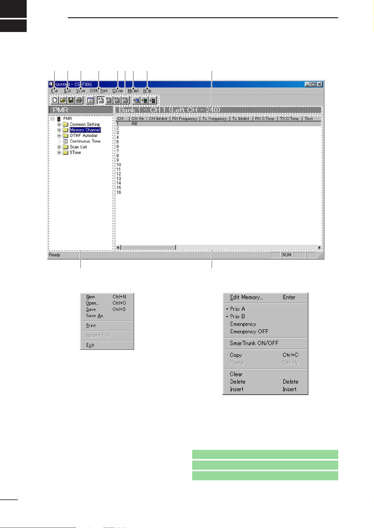
2-1 MAIN SCREEN DESCRIPTION
q FILE MENU— [File]
Used for making new files, opening available saved
files, saving memory channel contents or quitting the
program, etc. Up to 4 recently used files are indicated in the sub menu for simple, quick file selection.
w EDIT MENU— [Edit]
Edit the selected memory contents.
• Select the proper model type, item and channel
number before editing items. (see u, !0 and !1;p.3)
*The above sub-menu appears when ‘Memory Channel’ is
selected. When another item (e.g. Scan List) is selected,
a different sub-menu is appears in some cases.
2
SCREEN DESCRIPTION
2
Go to !0 TREE VIEW SCREEN
Go to !1 MEMORY CHANNEL SCREEN
Go to u MODEL MENU— [Model]
qwe r t u i oy
!0
!1
Page 5
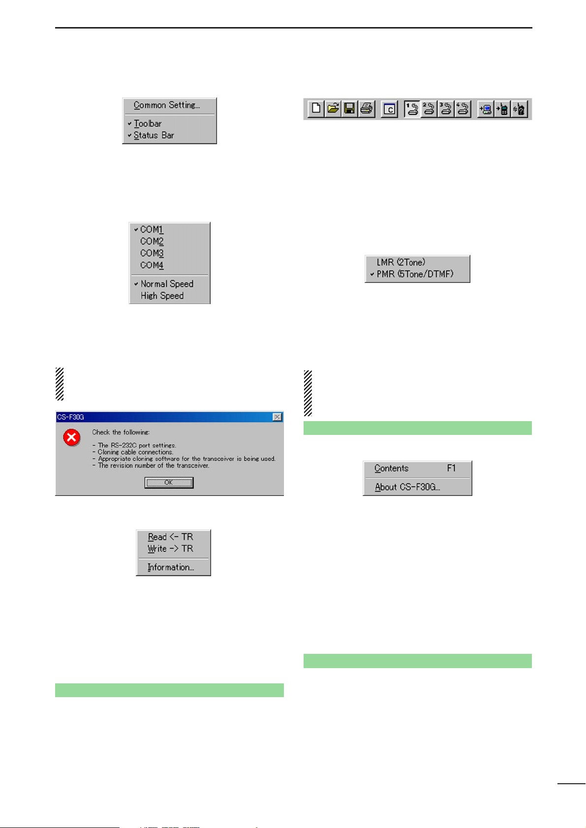
e VIEW MENU— [View]
• The independent Common Setting Screen is selectable. (pgs. 6–22)
• Turn the tool bar or status bar ON/OFF.
r COM PORT MENU— [COM Port]
Push to display the COM port setting sub menu.
• Set the COM port (RS-232C port) number properly.
• Select data transfer rate from Normal Speed and
High Speed.
NOTE: ‘Check the following’ dialog box as fol-
lows, appears when the RS-232C serial port is not
set correctly.
t CLONE MENU— [Clone]
Starts to read the programmed data from the connected transceiver, programs setup data to the connected transceiver, or displays detailed information
screen to check Model type, CPU’s revision number,
clone comment and optional unit installation condition of the connected transceiver.
The clone comment is programmed in Clone
Comment— (1), (2) in
3-2 COMMON 1
(p. 17).
y TOOL BAR
Short cut keys appear in the tool bar when the tool
bar is checked (“✔” mark appears) in the [View]
menu as above.
Short cut keys for New (Ctrl+N), Open (Ctrl+O), Save
(Ctrl+S) as in [File], Common Setting as in [View],
COM1–4 selection as in [COM Port] and
Read <– TR, Write –> TR, Information as in [Clone]
menu, are available.
u MODEL MENU— [Model]
Select the model type from LMR (2-tone) or PMR (5tone/DTMF).
-“✔” mark appears for the selected model.
The Tree View Screen content will be changed when
switched between LMR and PMR. See page 4 for
details.
IMPORT ANT! :
The model type must be selected
at first, otherwise the edited contents will be lost.
Select PMR (5Tone/DTMF) to enable the DTMF
decode operation.
i HELP MENU— [Help]
Push to display help contents and cloning software
revision information.
o EDIT CHANNEL INDICATION
Displays the prompt item name and channel number
to be edited.
!0 TREE VIEW SCREEN (p. 4)
Double click the folder icon or click the “ |+” beside
the folder which you want to edit. Then double click
the desired item name to display the item on the
‘Memory channel screen’.
!1 MEMORY CHANNEL SCREEN
Displays the Memory Channel or item information to
be edited. Double click, right click on the desired
channel number, or press [Enter] key after desired
channel selection, to open the independent ‘Edit’
screen.
3
SCREEN DESCRIPTIONS
2
Go to 2-2 TREE VIEW SCREEN DESCRIPTION
Go to 2-2 TREE VIEW SCREEN DESCRIPTION
Go to Clone Comment— (1), (2)
Page 6
4
SCREEN DESCRIPTIONS
2
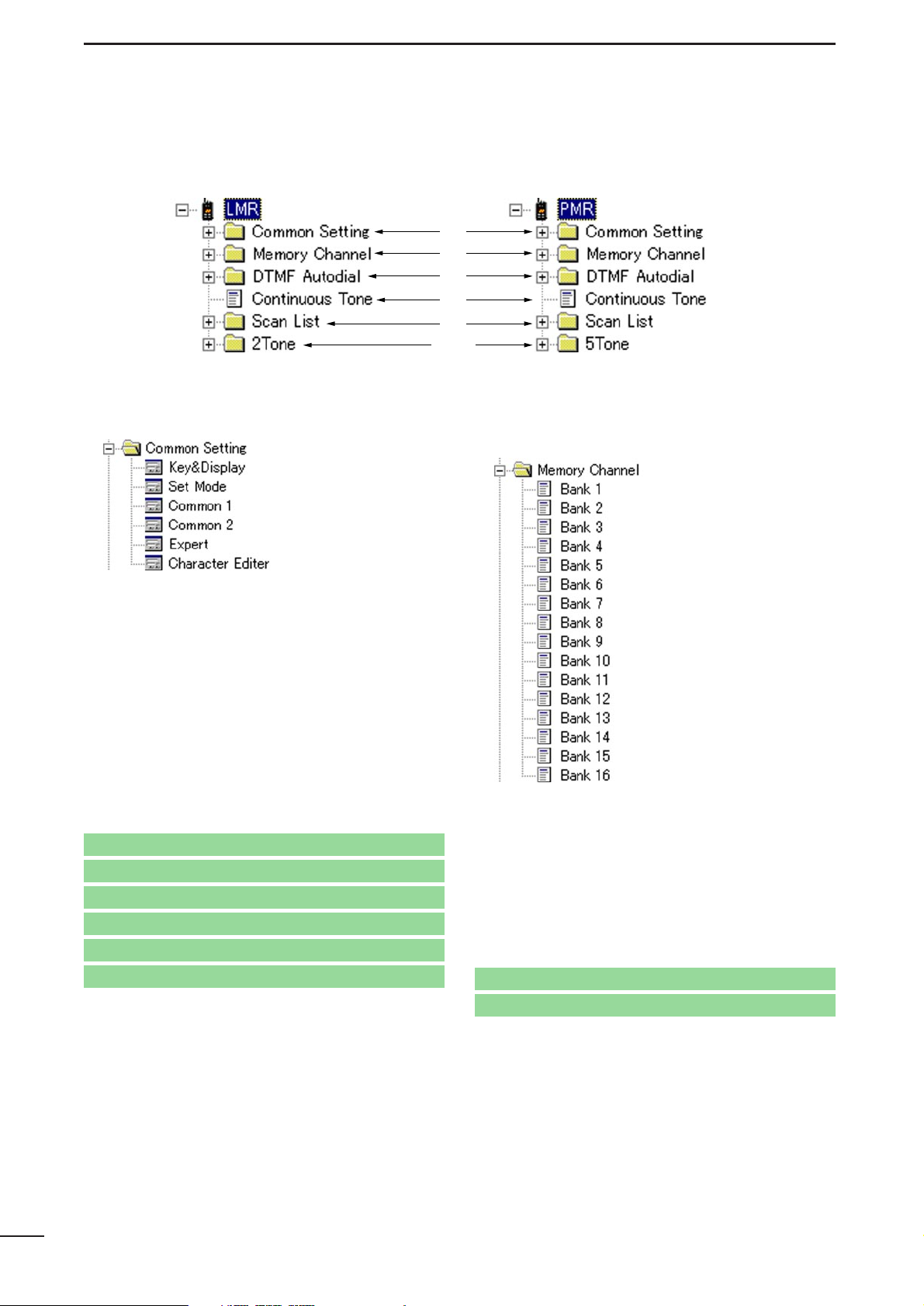
2-2 TREE VIEW SCREEN DESCRIPTION
q Common setting (pgs. 6–22)
Sets programmable key , function display assign, and
several commonly used timers, etc., are programmable in 6 independent sheets as follow.
Key & Display Assign
(pgs. 6–14)
Set Mode
(p. 15)
Common 1
(pgs. 16–17)
Common 2
(pgs. 18–19)
Expert
(pgs. 20–21)
Character Editor
(p. 22)
By double clicking an item in the Common Setting
folder, the desired sheet in the independent Common
Setting Screen appears.
w Memory Channel
(LMR: pgs. 23–28/PMR: pgs. 29–39)
Sets channel attribute, operating frequency, CTCSS
encoder/decoder frequency, transmit output power,
voice scrambling code, etc.
By double clicking a bank type item in the Bank
Setting folder, the desired bank condition is indicated
below the Memory Channel folder and channel number for editing in a bank in the Memory Channel
Screen.
q
w
e
r
t
yu
• LMR Tree View • PMR Tree View
Go to 3-1 KEY & DISPLAY ASSIGN
Go to 4 MEMORY CHANNEL— LMR
Go to 5 MEMORY CHANNEL— PMR
Go to 3-3 COMMON 1
Go to 3-4 COMMON 2
Go to 3-5 EXPERT
Go to 3-2 SET MODE
Go to 3-6 CHARACTER EDITOR
Page 7

e DTMF Autodial (pgs. 40–41)
Program DTMF code for the DTMF auto dialling
function and timers for each digit, 1st digit, [✽] and
[#] code.
By double clicking the DTMF Autodial item, the
DTMF channels for editing appear in the Memory
Channel Screen, and the independent DTMF Setting
Screen appears when the DTMF Setting item is double clicked.
r Continuous Tone (p. 42)
Set continuous tone frequency. The programmed
continuous tone is used for encoder and/or decoder.
By double clicking the Continuous Tone item, the
continuous tone channels for editing appear in the
Memory Channel Screen.
t Scan List (pgs. 43–44)
Sets scan mode, text for each scan group, power
save function scan stop/resume timers, etc.
By double clicking the Scan List item, the scan group
channels for editing appear in the Memory Channel
Screen, and the independent Scan Setting Screen
appears when the Scan Setting item is double
clicked.
y 2Tone (LMR only; pgs. 45–48)
Sets RX/TX code, text, beep, bell, stun, group call,
ANS functions, etc.
By double clicking the RX Code Channel item, the
RX code channels for editing appear in the Memory
Channel Screen, and the independent TX Code
Channel or 2Tone Setting Screen appears when the
TX Code Channel or 2Tone Setting item is double
clicked, respectively.
u 5Tone (PMR only; pgs. 49–58
Sets RX/TX code, text, 5-tone format, beep, bell,
stun, group call, answer back functions, etc.
By double clicking the RX/TX Code Channel, Format
or User Tone item, the RX/TX code channels for editing, 5-tone format or user tone appear in the Memory
Channel Screen, and the independent 5Tone Setting
Screen appears when the 5Tone Setting item is double clicked.
5
SCREEN DESCRIPTIONS
2
Go to 6 DTMF AUTODIAL
Go to 7 CONTINUOUS TONE
Go to 8 SCAN LIST
Go to 9 2TONE
Go to 10 5TONE
Page 8
COMMON SETTING
3
6
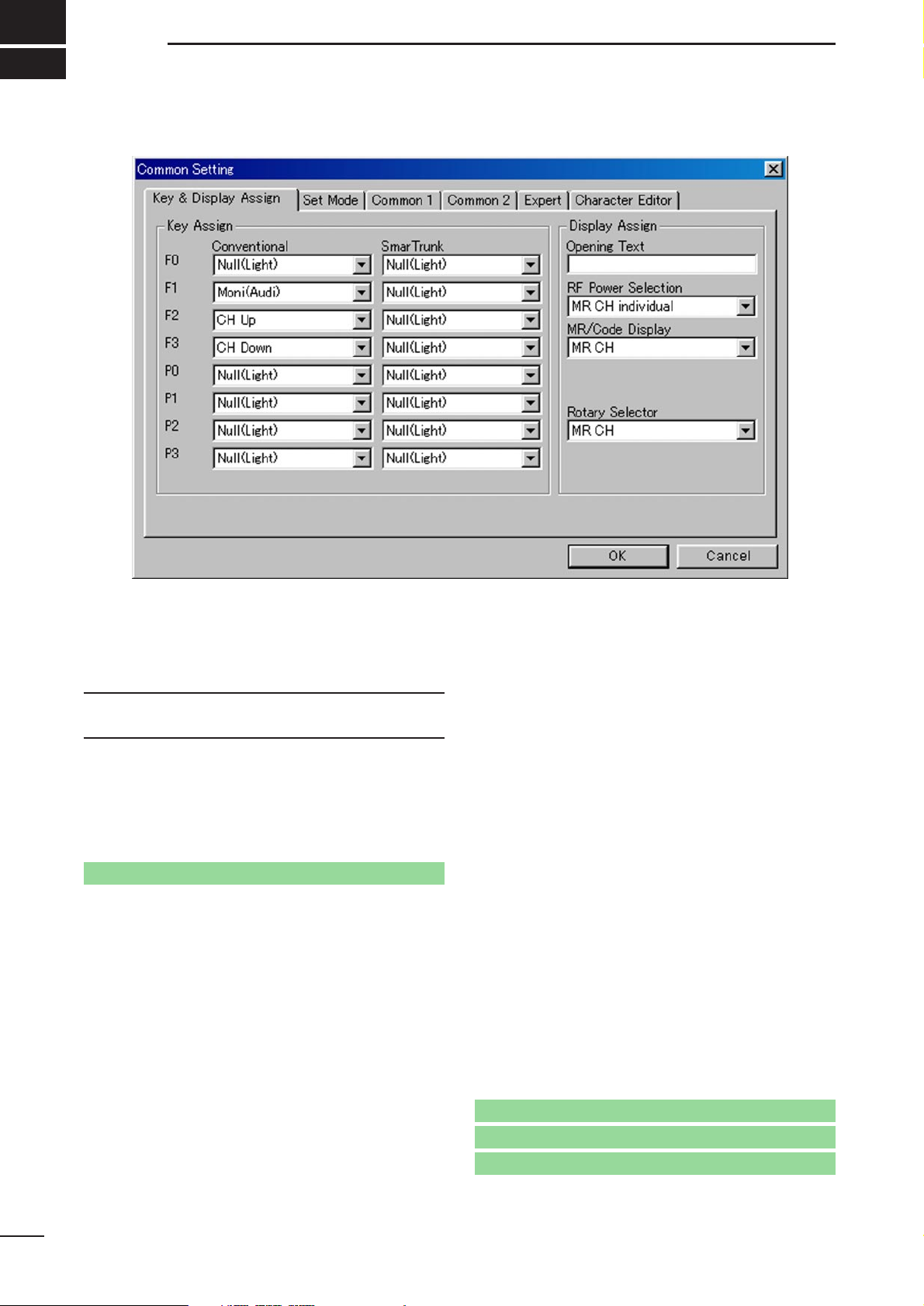
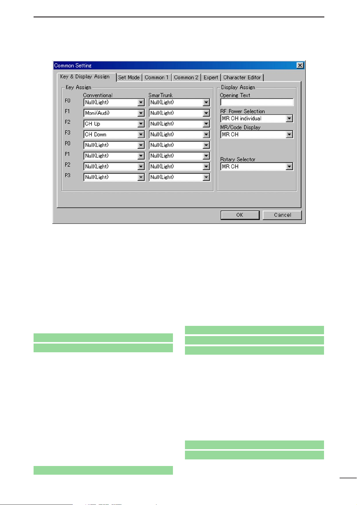
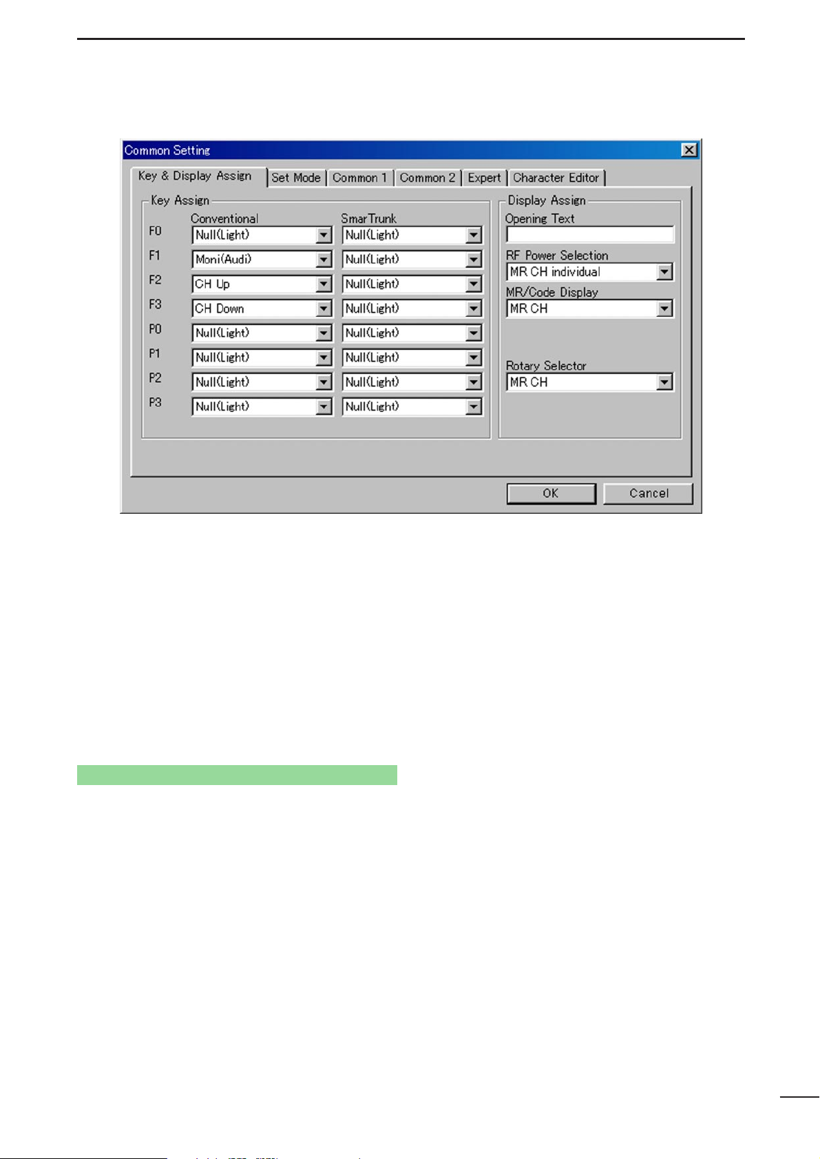
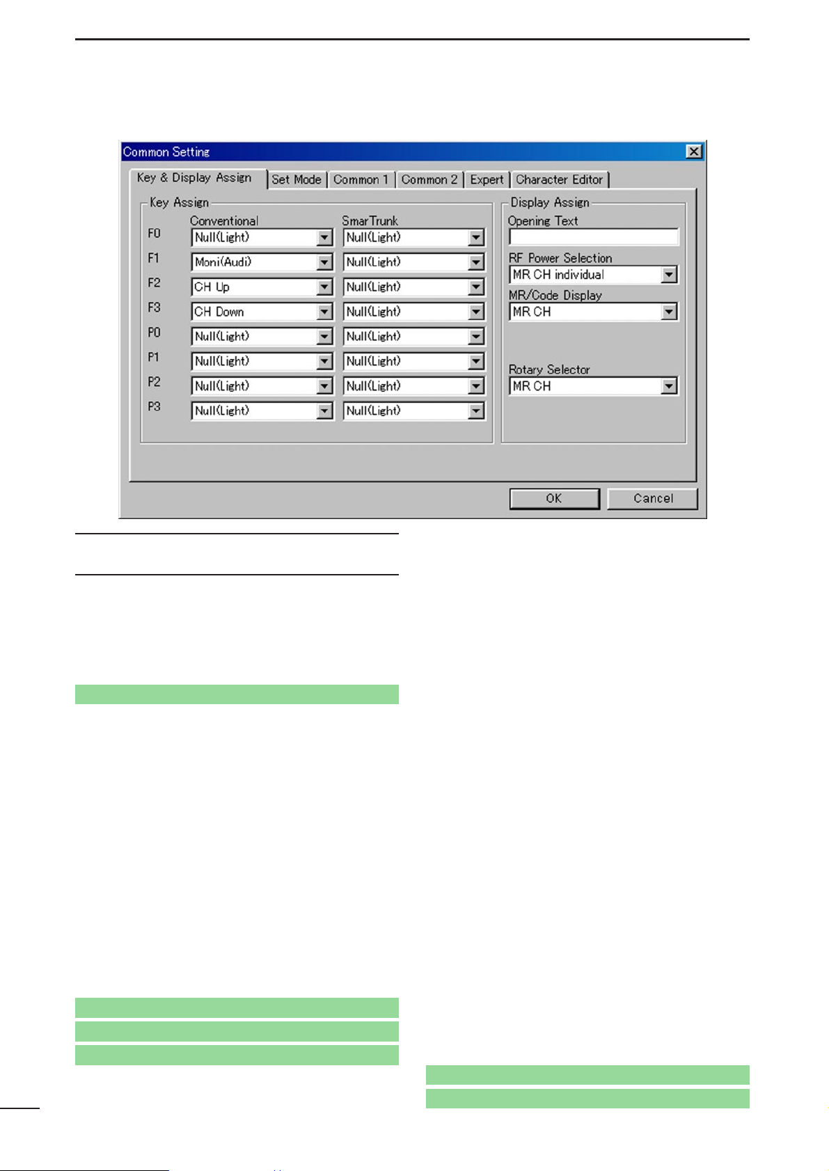
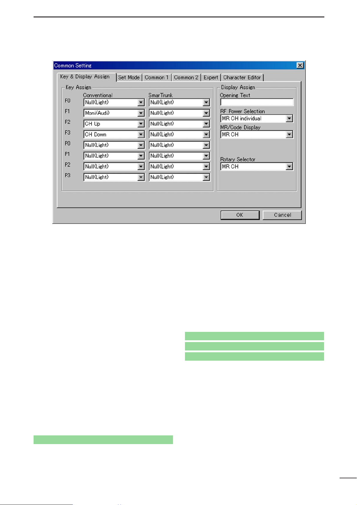
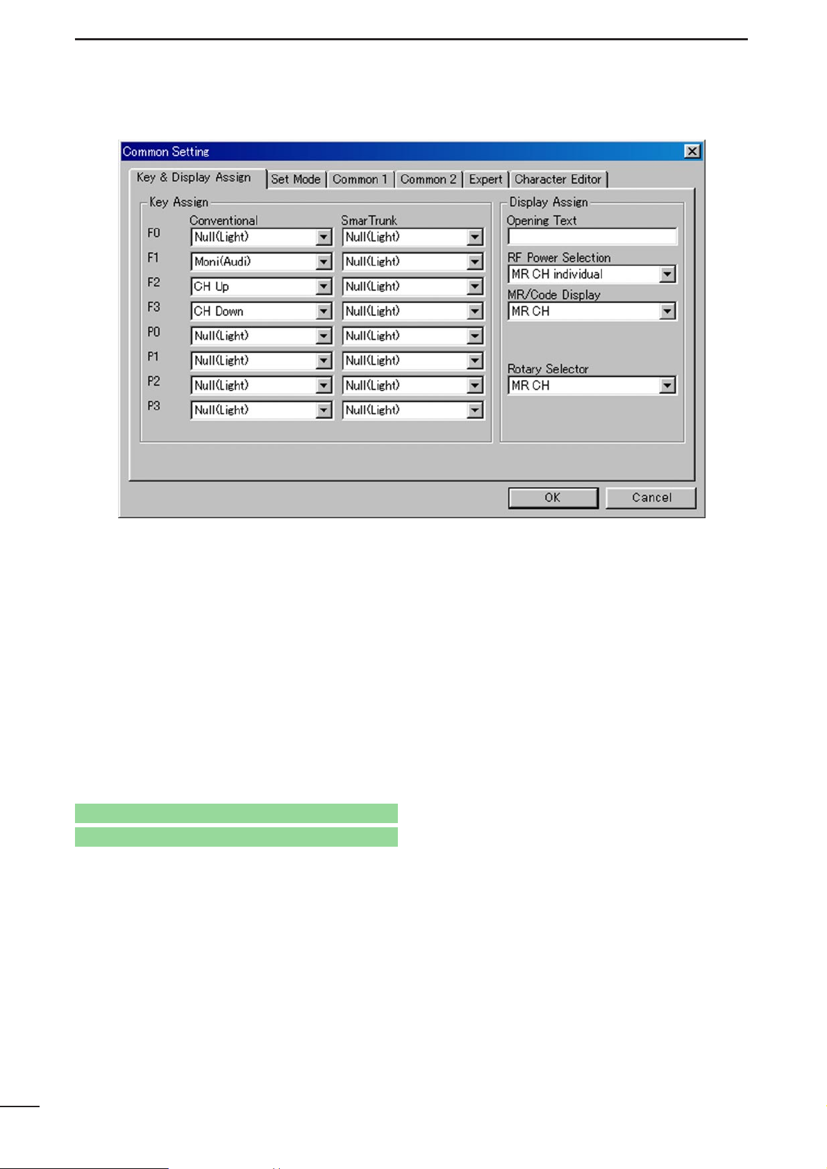
■ Key Assign—F0, F1, F2, F3, P0, P1, P2, P3
Assign a function for each programmable switch and
operating mode (Conventional and SmarTrunk).
Assignable functions and actions are as follows.
The following functions can be assigned for the
Conventional columns operation.
Null(Light):
No function is assigned. However, lights
LCD backlight for 5 sec. when ‘Auto’ is
selected in Backlight in
3-2 SET MODE
(p. 15).
CH Up, CH Down:
Changes the memory channel up or
down.
Bank : Push this switch then [CHUp] or [CH
Down] to change the memory channel
bank up or down.
Scan AStart/Stop, Scan B Start/Stop:
When the power ON scan function is turned OFF;
Push to start and cancel scanning operation. In case of transmission during scan,
cancels scanning when in Scan A, and
pauses scanning, then resumes scanning
after passing the time period specified in
Auto Reset in
4/5 MEMORY CHANNEL
(LMR; p. 27/PMR; p. 37) when Scan B is
selected.
The scanning list (scanning channel
group) can be selected via [CH Up] or
[CH Down] switches, after entering the
scan list selection mode by pushing this
switch for 1 sec.
When the power ON scan function is turned ON;
Push to pause scanning when in Scan A,
and push to cancel scanning when Scan
B is selected. In case of transmission during scan, pauses scanning, then resumes
scanning after passing the time period
specified in the Auto Reset in
4/5 MEM-
ORY CHANNEL
(LMR; p. 27/PMR; p. 37)
when in Scan A. Cancels scanning when
Scan B is selected.
The scanning list (scanning channel
group) can be selected via [CH Up] or
[CH Down] switches, after entering the
scan list selection mode by pushing this
switch for 1 sec.
The power ON scan function is specified in Power
ON Scan in
8-2 SCAN SETTING
(p. 44).
NOTE: Scan A and Scan B cannot be assigned at
the same time because the transceiver
cannot have two different scans.
Scan Add/Del(Tag):
Push to add or delete the channel to/from
the selected scanning list
3-1 KEY & DISPLAY ASSIGN
Go to Backlight
Go to Auto Reset— LMR
Go to Auto Reset— PMR
Go to PWR ON Scan
Page 9
7
COMMON SETTING
3
3-1 KEY & DISPLAY ASSIGN— continued
Prio A, Prio B:
Selects the priority channel A or B programmed in CH Atr in
4/5 MEMORY
CHANNEL
respectively (LMR; p. 23/PMR:
p. 29)
by pushing this switch.
Prio A (Rewrite):
Selects the priority channel A programmed in CH Atr in
4/5 MEMORY
CHANNEL
(LMR; p. 23/PMR: p. 29) by
pushing this switch. Also the operating
channel is re-assigned for priority channel
A by pushing this switch for 1 sec.
MR-CH 1–4:
Immediately selects memory channel 1–4
in the operating bank, respectively.
Moni/Moni(Audi):
For LMR model use— Moni
Push to mute and release the CTCSS
(DTCS) or 2-tone squelch mute. Open
any squelches/deactivate any mutes
while pushing this switch.
For PMR model use— Moni (Audi)
Activates a monitor function specified in
Switch Action— Moni in
5 MEMORY
CHANNEL— PMR
(p. 32).
Lock : Switches the keyboard lock function ON
and OFF.
High/Low : Switches the transmit output power level
from the independent settings of each
channel.
It is impossible to select “High” when
“Low” is selected for the initial setting in
RF PWR in
4/5 MEMORY CHANNEL
(LMR; p. 26/PMR; p. 36) as well as when
“MR CH Individual” is selected in the RF
Power Selection (p. 13) in this sheet.
C. Tone CH Ent:
Selects the continuous tone channel via
[CH Up] or [CH Down] switches to change
the tone frequency/code setting after
pushing this switch for temporary operation.
The [CH Up] or [CH Down] switches are
assigned in this screen (p. 6) and the continuous tone channel is programmed in
7 CONTINUOUS TONE
(p. 42).
Go to CH Atr— LMR
Go to CH Atr— PMR
Go to Switch Action— Moni
Go to RF PWR— LMR
Go to RF PWR— PMR
Go to RF Power Selection
Go to CH Up, CH Down
Go to 7 CONTINUOUS TONE
Page 10
3-1 KEY & DISPLAY ASSIGN— continued
Talk Around:
Switches the talk around function ON and
OFF.
This function allows temporary simplex
operation on the duplex/repeater channel.
Wide/Narrow:
Switches both transmission and reception
IF passband width for temporary wide or
narrow channel spacing operation.
After channel or bank selection, the passband width returns to the original selection.
The original passband width is programmed in Wide/Narrow in
4/5 MEMO-
RY CHANNEL
(LMR: p. 26/PMR: p.35).
DTMF Autodial:
Push to enter the DTMF autodial mode
and then select the stored DTMF code via
[CH Up] or [CH Down] switches.
Transmits the selected DTMF code by
pushing this switch for 1 sec.
The DTMF code for auto dialling is programmed in
6-1 DTMF AUTODIAL
(p. 40),
and the [CH Up] or [CH Down] switches
are assigned in this screen (p. 6).
Re-Dial : Transmits the last-transmitted DTMF
code again. Acts for both manual and
autodial.
Re-Dial will be cleared when the transceiver is turned OFF once.
Call : Transmits the 2-tone (LMR) or 5-tone or
DTMF code (PMR) in the selected channel.
2-tone is programmed in 2Tone in
4 MEM-
ORY CHANNEL— LMR
(p. 25).
5-tone is programmed in 5Tone
Signaling— RPT, STN, ID in
5 MEMORY
CHANNEL— PMR
(p. 34).
For PMR model use only
In case this switch is pushed, and the 5tone setting is an “OFF” channel, it transmits the previously transmitted 5-tone
code, when the automatic clear channel
searching function is activated, which is
specified in the Auto CH Call in
8-2 SCAN
SETTING
(p. 44).
8
COMMON SETTING
3
Go to 6-1 DTMF Autodial
Go to CH Up, CH Down
Go to Auto CH Call
Go to 2Tone
Go to 5Tone Signaling— RPT, STN, ID
Go to Wide/Narrow— LMR
Go to Wide/Narrow— PMR
Page 11
9
COMMON SETTING
3
3-1 KEY & DISPLAY ASSIGN— continued
Call A (Code 30), Call B (Code 29)—
PMR only
:
Transmits the 5-tone code programmed in
the channel 30 (Call A) or 29 (Call B) in 10-
2 TX CODE (p. 52) as the station code,
when [Call A] or [Call B] switch is pushed
respectively.
Emergency Single, Emergency Repeat :
Immediately selects emergency channel
and automatically sends a repeated
emergency signal at specified time intervals, or an emergency signal once, by
pushing this switch for the specified time
period, programmed in Emergency—
SW ON Timer in
3-5 EXPERT
(p. 20).
Also, cancels the emergency call by pushing this switch for the specified time period, programmed in Emergency— SW
OFF Timer in (p. 20), before an emer-
gency signal is transmitted.
The emergency channel is specified in CH
Atr in
4/5 MEMORY CHANNEL
(LMR;
p. 23/PMR; p. 29)
and the time intervals are
specified in the Emergency—
Start/Repeat in
3-5 EXPERT
(p. 21).
TX Code—
PMR only
:
Selects a TX code channel, instead of the
specified 5-tone code channel programmed in 5Tone signaling— STN in
5
MEMORY CHANNEL— PMR
(p. 34), via
[CH Up] or [CH Down] switches after
pushing this switch for temporary operation.
The station code can also be manually
entered as follows.
To enter 5-tone code—
IC-F30GT/F40GT, IC-F31GT/F41GT:
Enter the station code using [0]–[9] and [✽]
switches after pushing this switch for 1 sec.
IC-F30GS/F40GS, IC-F31GS/F41GS:
Select the code number via [CH Up] or
[CH Down] switches after pushing this switch for
1 sec., then push this switch to set the next code
number. After all digits are selected, push this
switch for 1 sec. to complete the number.
Selectable 5-tone channels, acceptable input digits and updates can be specified in Sel (p. 53),
Input Digit (p. 52) and Update (p. 53) in
10-2 TX
CODE CHANNEL
.
The [CH Up] and [CH Down] switches are
assigned in this screen (p. 6).
Go to Emergency— SW ON Timer
Go to Emergency— SW OFF Timer
Go to 5Tone signaling— STN
Go to Sel
Go to Input Digit
Go to Update
Go to CH Atr— LMR
Go to CH Atr— PMR
Go to Emergency— Start/Repeat Go to CH Up, CH Down
Go to 10-2 TX Code
Page 12
10
COMMON SETTING
3
3-1 KEY & DISPLAY ASSIGN— continued
TX Code CH Up, TX Code CH Down—
PMR only
:
Selects a TX code channel, instead of the
specified 5-tone code channel programmed in 5Tone signaling— STN in
5
MEMORY CHANNEL— PMR
(p. 34)
for
temporary operation.
Selectable 5-tone channels are specified
in Sel in
10-2 TX CODE CHANNEL
(p. 53).
ID-MR Select—
PMR only
:
For entering into the received ID code history indication mode. Up to 5 codes can
be memorized, and searches the history
with [CH Up] or [CH Down] switches.
All the history can be cleared by pushing
this switch for 1sec.
The selected/displayed 5-tone code can
be transmitted as STN (station/group)
code when [Call] switch is pushed.
[CH Up], [CH Down] or [Call] switches are
assigned in this screen (pgs. 6, 8).
Scrambler:
Switches the voice scrambler function ON
and OFF when an optional voice scrambler unit, UT-109 or UT-110, is installed.
When “Inhibit” is selected in Scrambler—
OFF, ON, Inhibit in
4/5 MEMORY CHAN-
NEL
(LMR; p. 26/PMR; p. 39), the scram-
bler function cannot be switched on with
this switch operation.
Compander:
Switches the compander function ON and
OFF.
The compander function reduces noise
components from the transmitting audio
to provide clear communication.
Go to CH Up, CH Down
Go to 5Tone signaling— STN
Go to Sel
Go to Scrambler— OFF, ON, Inhibit— LMR
Go to Call
Go to Scrambler— OFF, ON, Inhibit— PMR
Page 13
11
COMMON SETTING
3
3-1 KEY & DISPLAY ASSIGN— continued
User Set Mode:
Entering into the
User Set Mode
by push-
ing this switch for 1 sec.
The
User Set Mode
is used for programming infrequently changed values or conditions of functions without PC programming.
Push this switch momentarily to select the
function, and push [CH Up] or [CH Down]
to change the setting, after entering into
the
User Set Mode
.
Programmable functions are selected in
3-2 SET MODE
(p. 15).
OPT11 Out/H, OPT12 Out/H, OPT13 Out/H:
Outputs “High” level signal from the
OPT1–3 ports in the optional unit connector (MAIN unit, J1; pins 9–11), respectively.
OPT11 Out/L, OPT12 Out/L, OPT13 Out/L:
Outputs “Low” level signal from the
OPT1–3 ports in the optional unit connector (MAIN unit, J1; pins 9–11), respectively.
OPT11 Momentary/H, OPT12 Momentary/H,
OPT13 Momentary/H:
Outputs “High” level pulse signal from the
OPT1–3 ports in the optional unit connector (MAIN unit, J1; pins 9–11), respectively.
OPT11 Momentary/L, OPT12 Momentary/L,
OPT13 Momentary/L:
Outputs “Low” level pulse signal from the
OPT1–3 ports in the optional unit connector (MAIN unit, J1; pins 9–11), respectively.
OPT21 Out/H, OPT22 Out/H, OPT23 Out/H:
Outputs “High” level signal from the
OPT1–3 ports in the optional unit connector (MAIN unit, J2; pins 9–11), respectively.
OPT21 Out/L, OPT22 Out/L, OPT23 Out/L:
Outputs “Low” level signal from the
OPT1–3 ports in the optional unit connector (MAIN unit, J2; pins 9–11), respectively.
OPT21 Momentary/H, OPT22 Momentary/H,
OPT23 Momentary/H:
Outputs “High” level pulse signal from the
OPT1–3 ports in the optional unit connector (MAIN unit, J2; pins 9–11), respectively.
OPT21 Momentary/L, OPT22 Momentary/L,
OPT23 Momentary/L:
Outputs “Low” level pulse signal from the
OPT1–3 ports in the optional unit connector (MAIN unit, J2; pins 9–11), respectively.
Sp. Func 1, Sp. Func 2:
Reserved for future functions.
Go to 3-2 SET MODE
Page 14
12
COMMON SETTING
3
3-1 KEY & DISPLAY ASSIGN— continued
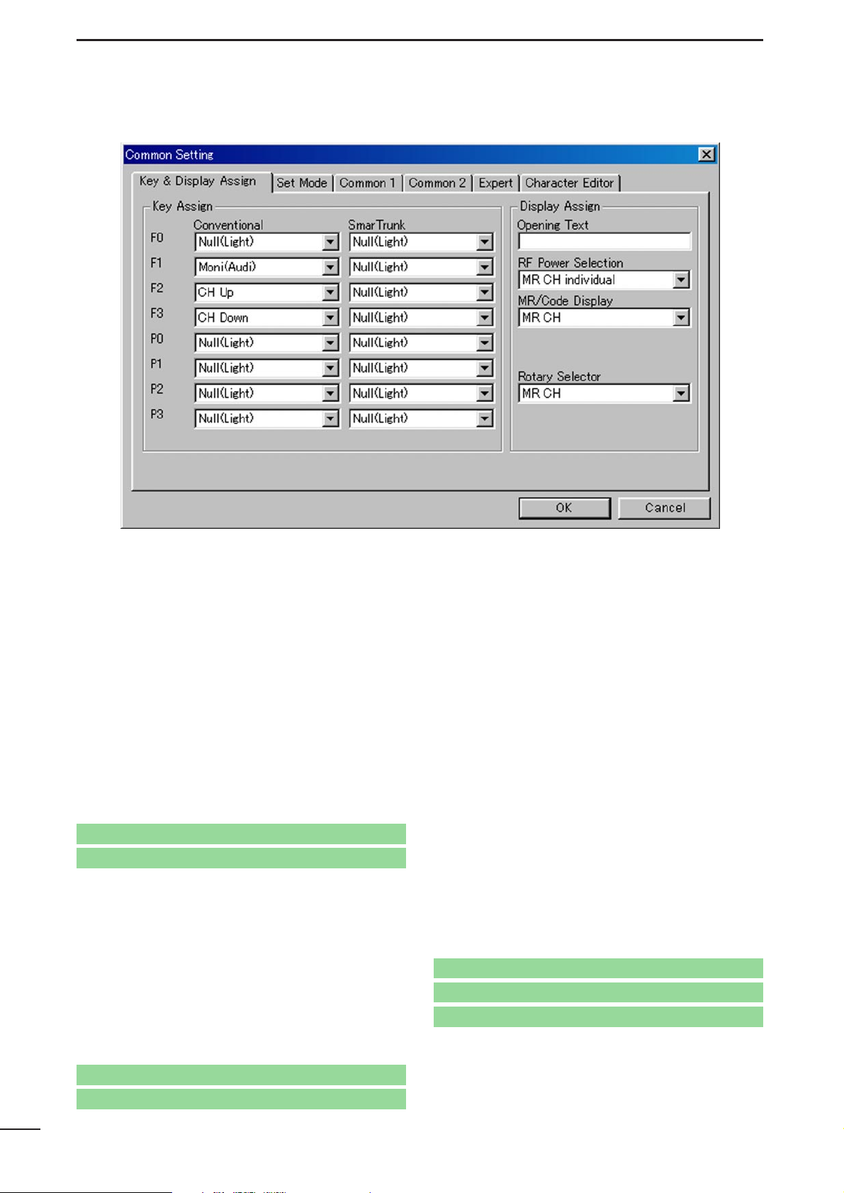
The following functions can be assigned for the
SmarTrunk columns operation.
Null(Light):
No function is assigned. However, lights
LCD backlight for 5 sec. when ‘Auto’ is
selected in Backlight in
3-2 SET MODE
(p. 15).
Bank : Push this switch then [CHUp] or [CH
Down] to change the memory channel
bank up or down.
Lock : Switches the keyboard lock function ON
and OFF.
High/Low : Switches the transmit output power level
from the independent settings of each
channel.
It is impossible to select “High” when
“Low” is selected for the initial setting in
RF PWR in
4/5 MEMORY CHANNEL
(LMR; p. 26/PMR; p.36), and also when
“MR CH Individual” is selected in the RF
Power Selection (p. 13) in this sheet.
Trunking Group SW:
Selects trunking group.
Turbo SpeeDial A, B, C, D:
Immediately calls commonly used telephone or subscriber numbers during
SmarTrunk II operation. See pages 00–00
for details
✽, # : Acts as [✽] or [#] keys on 10-key pad.
Convenient during SmarTrunk II operation with non-keypad type transceivers
(IC-F30GS/F40GS, IC-F31GS/F41GS).
Assign these functions to the keys in
which [CH Up] or [CH Down] is assigned
in conventional operation.
Scrambler:
Switches the voice scrambler function ON
and OFF when an optional voice scrambler unit, UT-109 or UT-110, is installed.
When “Inhibit” is selected in Scrambler—
OFF, ON, Inhibit in
4/5 MEMORY CHAN-
NEL
(LMR; p. 26/PMR; p. 39), the scram-
bler function cannot be switched on with
this switch operation.
Go to RF PWR— LMR
Go to RF PWR— PMR
Programming memory Speed Dial
q Push and hold [✽] until a high-pitch beep is heard.
w Enter the memory location (0–9), the telephone or subscriber
number, then [1], [✽] (or [3], [✽] if for another system subscriber).
• Ahigh-pitch beep informs of successful programming.
• Memories [A]–[D] are used for the Turbo SpeeDial.
Note: This function is available for the IC-F30GT/F40GT and
IC-F31GT/F41GT only.
Go to RF Power Selection
Go to Backlight
Go to Scrambler— OFF, ON, Inhibit— LMR
Go to Scrambler— OFF, ON, Inhibit— PMR
Page 15
3-1 KEY & DISPLAY ASSIGN— continued
Compander:
Switches the compander function ON and
OFF.
The compander function reduces noise
components from the transmitting audio
to provide clear communication.
Sp. Func 1, Sp. Func 2:
Reserved for future functions.
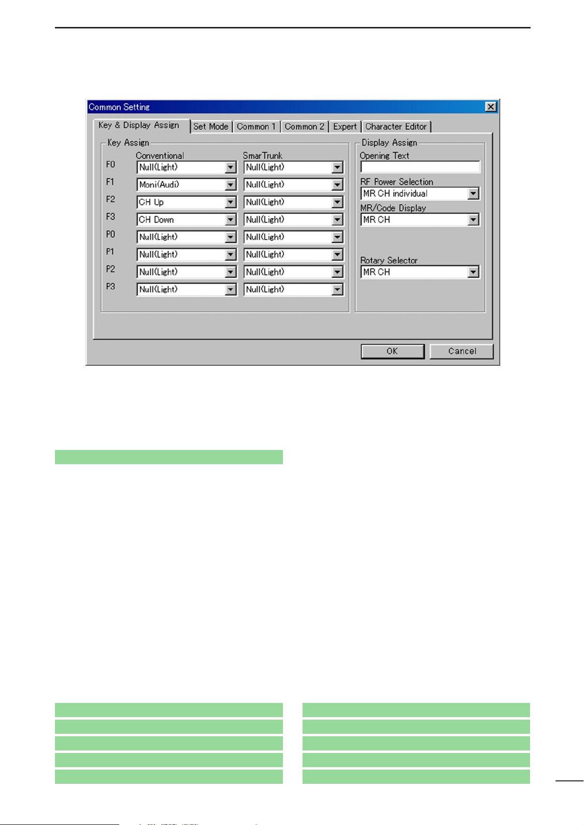
■ Display Assign
• Opening Text
Enter up to a 12-character transceiver opening message.
The usable characters are A–Z, a–z, 0–9, $, ’, (, ), –,
/, <, =, >, @, [, \, ], _, {, |, } ~ and user original characters.
When entering user original characters, enter ‘%’and
the desired thumbnail number A to P (capital letter
only).
Programming example:
When entering original character’s thumbnail number C, enter as ‘%C.’
User original characters are programmed in
3-6
CHARACTER EDITOR
(p. 22).
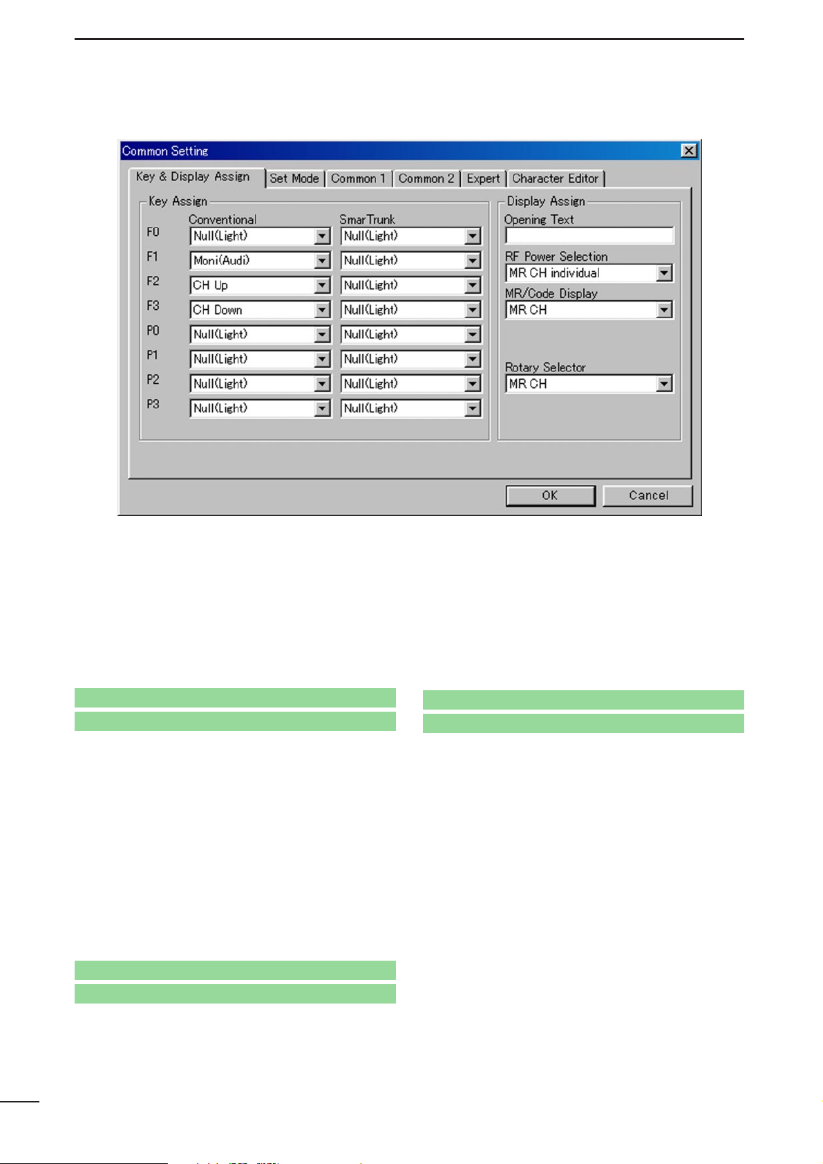
• RF Power Selection
Selects the transmit output power setting condition
from MR CH individual and Override.
Selected transmit output power level with the
[High/Low] switch is kept for all channels regardless
of the individual power setting programmed in RF
PWR in
4/5 MEMORY CHANNEL
(LMR; p. 26/PMR;
p. 36)
when ‘Override’ is selected. However, outputs
selected transmit output power level temporarily with
the [High/Low] switch when ‘MR CH Individual’ is
selected.
The [High/Low] switch is assigned in this screen
(p. 7).
13
COMMON SETTING
3
Go to RF PWR— LMR
Go to RF PWR— PMR
Go to High/Low
Go to 3-6 CHARACTER EDITOR
Page 16
14
COMMON SETTING
3
3-1 KEY & DISPLAY ASSIGN— continued
• MR/Code Display—
PMR only
Selects the display conditions from MR CH and
MR CH+TX CODE CH.
MR CH
: The selected operating channel number or
programmed text only is displayed.
MR CH+TX Code CH:
The selected operating channel and transmit 5-tone code channel number or programmed text are displayed.
Text for each operating channel and transmit 5-tone
code channel are programmed in Frequency— Text
in
5 MEMORY CHANNEL
(p. 30) and in Text in
10-2
TX CODE CHANNEL
(p. 52), respectively.
When no text is programmed, the selected channel
number is displayed instead of the text.
• Rotary Selector
Selects the [Rotary Selector] action from MR CH, MR
CH (Home) and Bank.
MR CH : Selects memory channel.
MR CH (Home): Selects memory channel and
starts scanning automatically
when channel 1 is selected.
Bank : Selects memory bank.
NOTE: DO NOT select “MR CH” or “MR CH (Home)”
when [CH Up]/[CH Down] is assigned, or
“Bank” when [Bank] is assigned to either
F0–F3 and P0–P3 switches. A cloning error
may occur.
Go to Frequency— Text
Go to Text
Page 17
15
COMMON SETTING
3
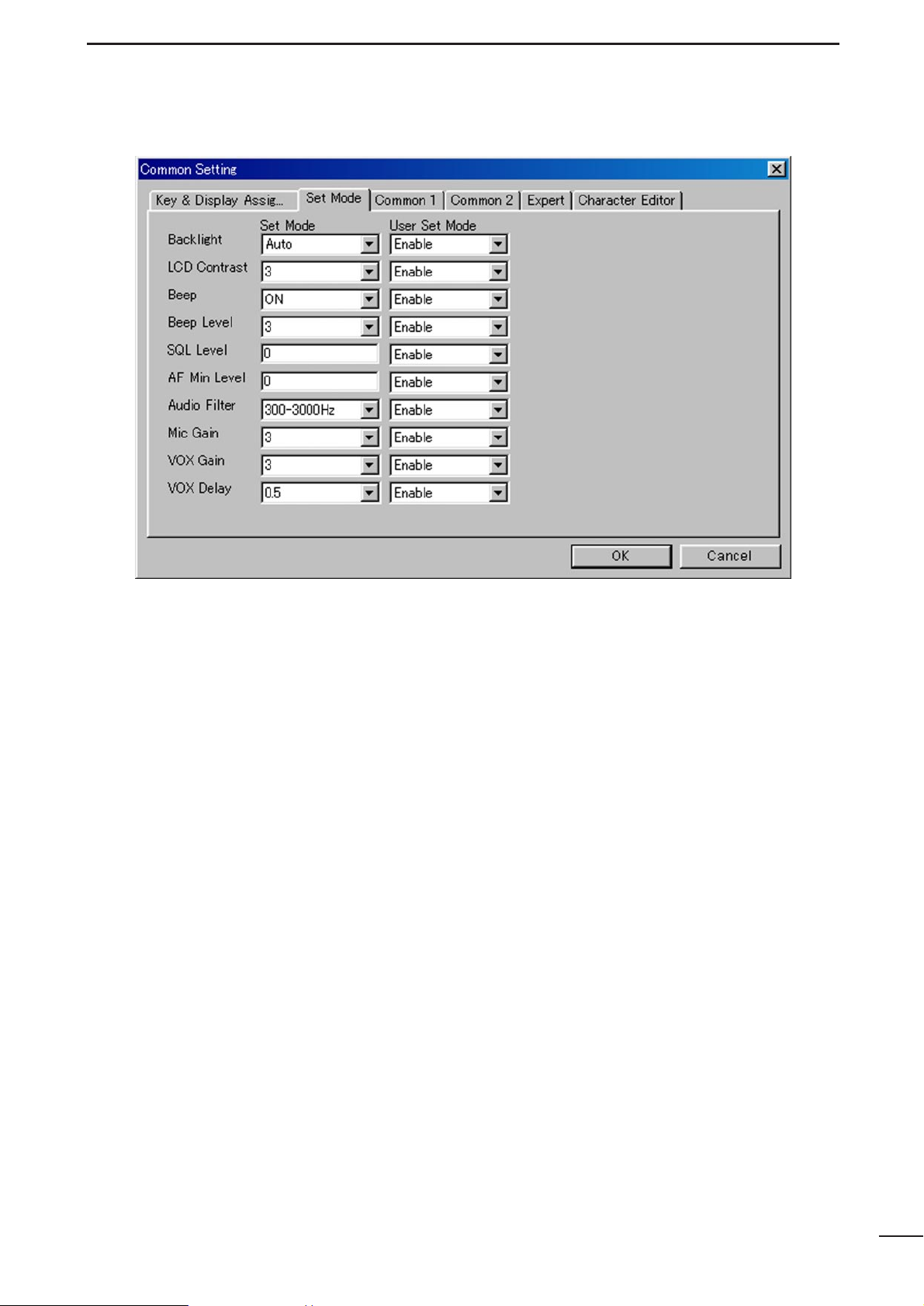
3-2 SET MODE
Set the values or conditions of the following functions
in the Set Mode columns, and select the conditions
of User Set Mode from Enable and Inhibit.
These functions are for programming infrequently
changed values or conditions without PC programming.
The function which “Inhibit” is selected, does not
appear and therefore cannot be set in the User Set
Mode.
• Backlight
Selects the LCD backlight lighting conditions from
ON, OFF and Auto.
ON
: Lights continuously while the transceiver is
powered ON.
OFF : Does not light with any operation.
Auto : Lights for 5 sec. when any switch except
[PTT] is pushed.
• LCD Contrast
Selects the LCD contrast level from 1–5.
• Beep
Selects the key-touch beep output capability . (Not for
lockout timer, TOT, etc.)
• Beep Level
Selects the key-touch beep fixed output level from
1–5, or minimum output level from
1(Linked)–5(Linked).
When either minimum output level is selected, the
beep output level is adjustable with [VOL] control.
• SQL Level
Enter a value within a 0–255 range for noise squelch
threshold level adjustment.
• AF Min Level
Enter a value within a 0–255 range for minimum
audio output level.
• Audio Filter
Selects the audio filter from 300–3000 Hz,
0–3000 Hz, 300–3400 Hz and 0–3400 Hz.
• Mic Gain
Selects the internal microphone gain from 1–5.
• VOX Gain
Selects the VOX gain from OFF and 1–5.
• VOX Delay
Selects the VOX delay from 0.5, 1.0, 1.5, 2.0, 2.5
and 3.0.
Page 18
16
SCREEN MENU OPERATION—LMR
3
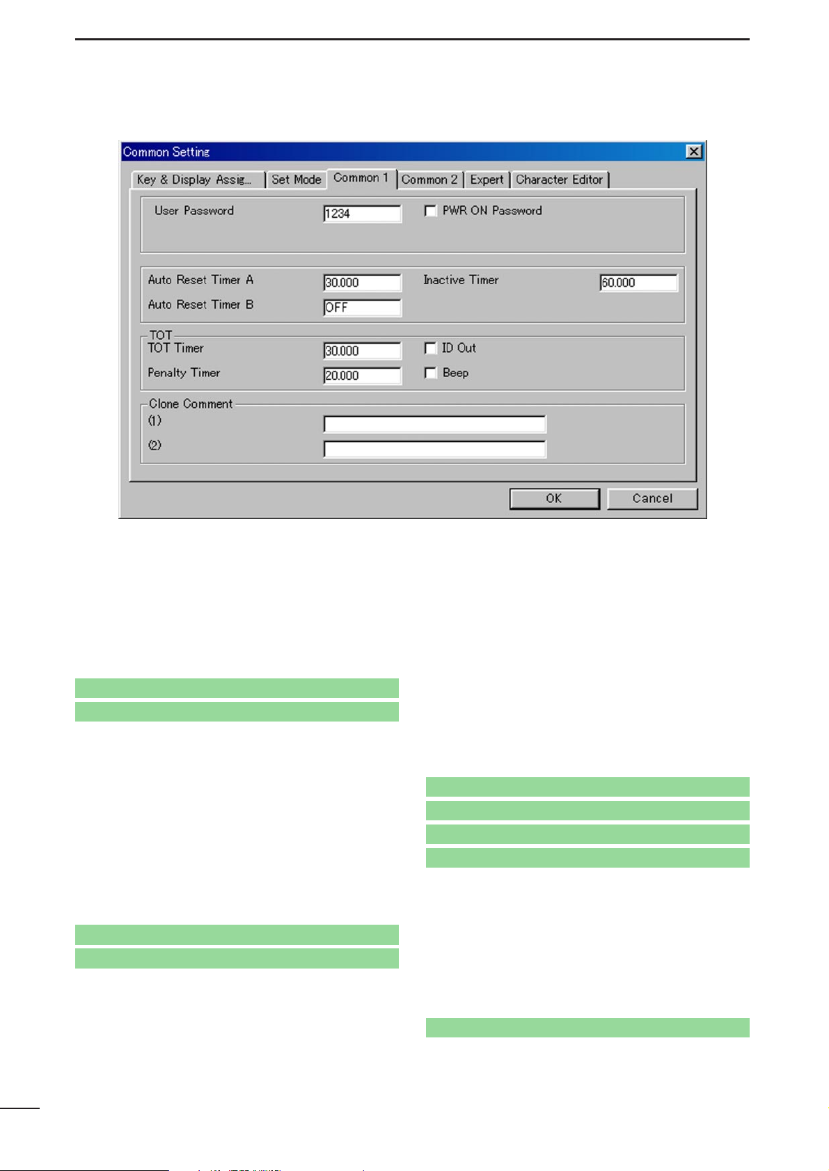
3-3 COMMON 1
• User Password
Enters up to a 4-digit user password for the power
ON password function or for cancelling the “Stun”
condition.
The power ON password function is specified in
PWR ON Password as follows, and the “Stun” function is specified in Stun in
9-1/10-1 RX CODE
CHANNEL
(2-tone; p. 46, 5-tone; p. 51).
• PWR ON Password
Click the check-box to activate the power ON password function.
It is necessary to enter the 4-digit password programmed in the User Password as above when
checked. However, the password must be entered
after receiving a “Stun” signal regardless of this setting.
The Stun condition is programmed in Stun in
9-1/10-
1 RX CODE CHANNEL
(2-tone; p. 46, 5-tone; p. 51).
• Auto Reset Timer A, Auto Reset Timer B
Enter the time
period for returning the mute condition
to the initial setting, specified in CH Mute in
5 MEM-
ORY CH
(PMR only; p. 38), and/or restarting the scan
from a disappearing signal, or when key operation is
finished, if the power ON scan function is turned ON.
To turn OFF the Auto Reset function, enter “0 (zero)”
to one of these settings. (“OFF” will be indicated)
The programmed settings are selected in Auto
Reset in
4/5 MEMORY CHANNEL
(LMR; p. 27/PMR;
p. 37)
.
The power ON scan function is programmed in
Power ON Scan in
8-2 SCAN SETTING
(p. 44).
• Inactive Timer—
PMR only
The entered time period acts as the Auto
Reset Timer A,
Auto Reset Timer B as above.
This setting is used with the Auto Rest Timer A or
Auto Rest Timer B, by selecting ‘Timer A Inact’ or
‘Timer B Inact’ in Auto Reset in
5 MEMORY CHAN-
NEL
(p. 37).
Go to Stun— 2-tone
Go to Stun— 5-tone
Go to Stun— 2-tone
Go to Stun— 5-tone
Go to CH Mute
Go to Auto Reset— LMR
Go to Auto Reset— PMR
Go to Power ON Scan
Go to Auto Reset— PMR
Page 19
17
COMMON SETTING
3
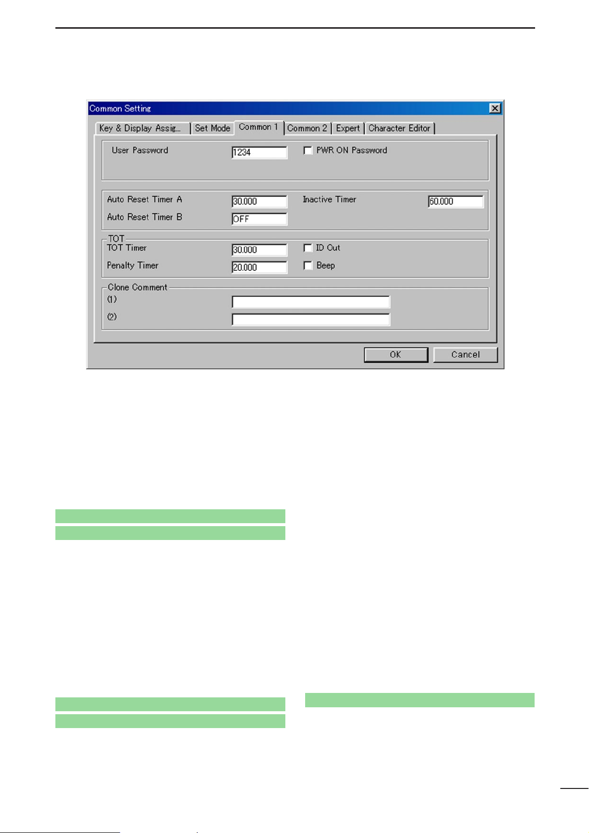
3-3 COMMON 1— continued
• TOT— TOT Timer
Enters the continuously transmittable time period
(Time-out timer). Maximum time period is specified for
30, 60 or 180 sec. etc., according to country and
local regulations.
The time-out timer function can be turned ON or OFF
for each operating channel in TOT in
4/5MEMORY
CHANNEL
(LMR; p. 28/PMR; p. 39).
DO NOT set to only a few seconds, as transmitting
will be impossible.
• TOT— ID Out (DTMF)/ID Out
Click the check-box to activate the automatic ID
transmission capability.
-The “✔” mark appears in the check-box when checked.
The function automatically transmits an ID code
when the time-out timer activates, and just before
transmission is inhibited.
The ID code is programmed in
No. Log/ID
in
6-1
DTMF AUTODIAL
(p. 40) for LMR, and is specified in
5Tone Signaling— ID in
5 MEMORY CHANNEL
(p. 34) for PMR operation.
• TOT— Penalty Timer
Enters the un-transmittable time period for penalty
when the continuously transmitted time has exceeded the specified time period programmed in TOT—
TOT Timer as at left.
The TOT penalty time is the transmit inhibit period
when the time-out timer is activated.
• TOT— Beep
Click the check-box to activate the warning beep output capability for TOT function.
-The “✔” mark appears in the check-box when checked.
Emits warning beep 10 sec. before compulsory shut
down of the transmission.
The transceiver emits warning beeps 10 sec. before,
and the time-out timer activates when this setting is
turned ON.
• Clone Comment— (1), (2)
Enters up to a 16-character text for quick identification of a transceiver’s content.
The programmed comment of the connected transceiver can be checked without reading all other existing programmed data. See t CLONE MENU—
[Clone] in
2-1 MAIN SCREEN DESCRIPTION
(p. 3).
Go to TOT— LMR
Go to TOT— PMR
Go to 6-1 DTMF AUTODIAL
Go to 5Tone Signaling— ID
Go to u CLONE MENU— [Clone]
Page 20
18
SCREEN MENU OPERATION—LMR
4
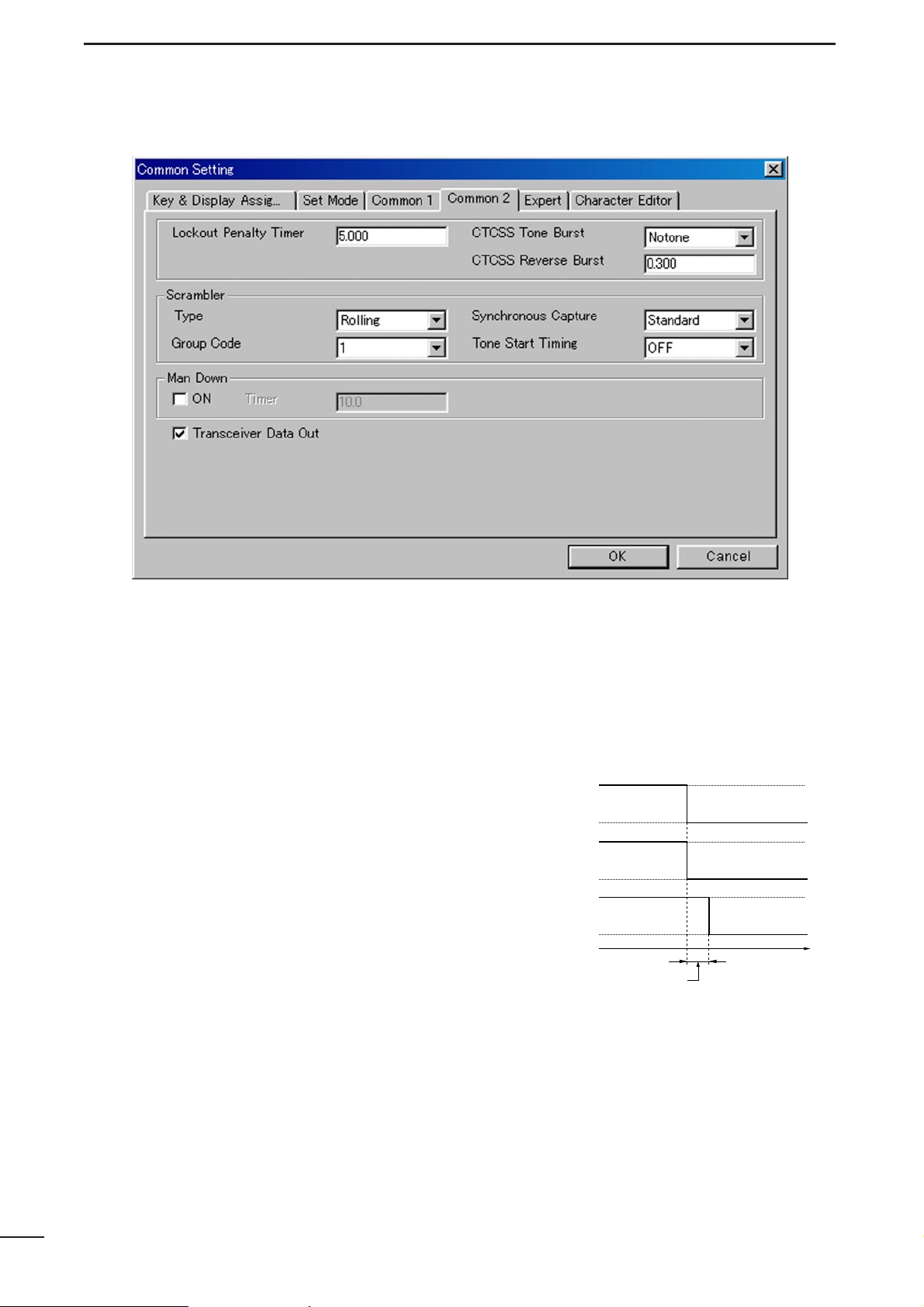
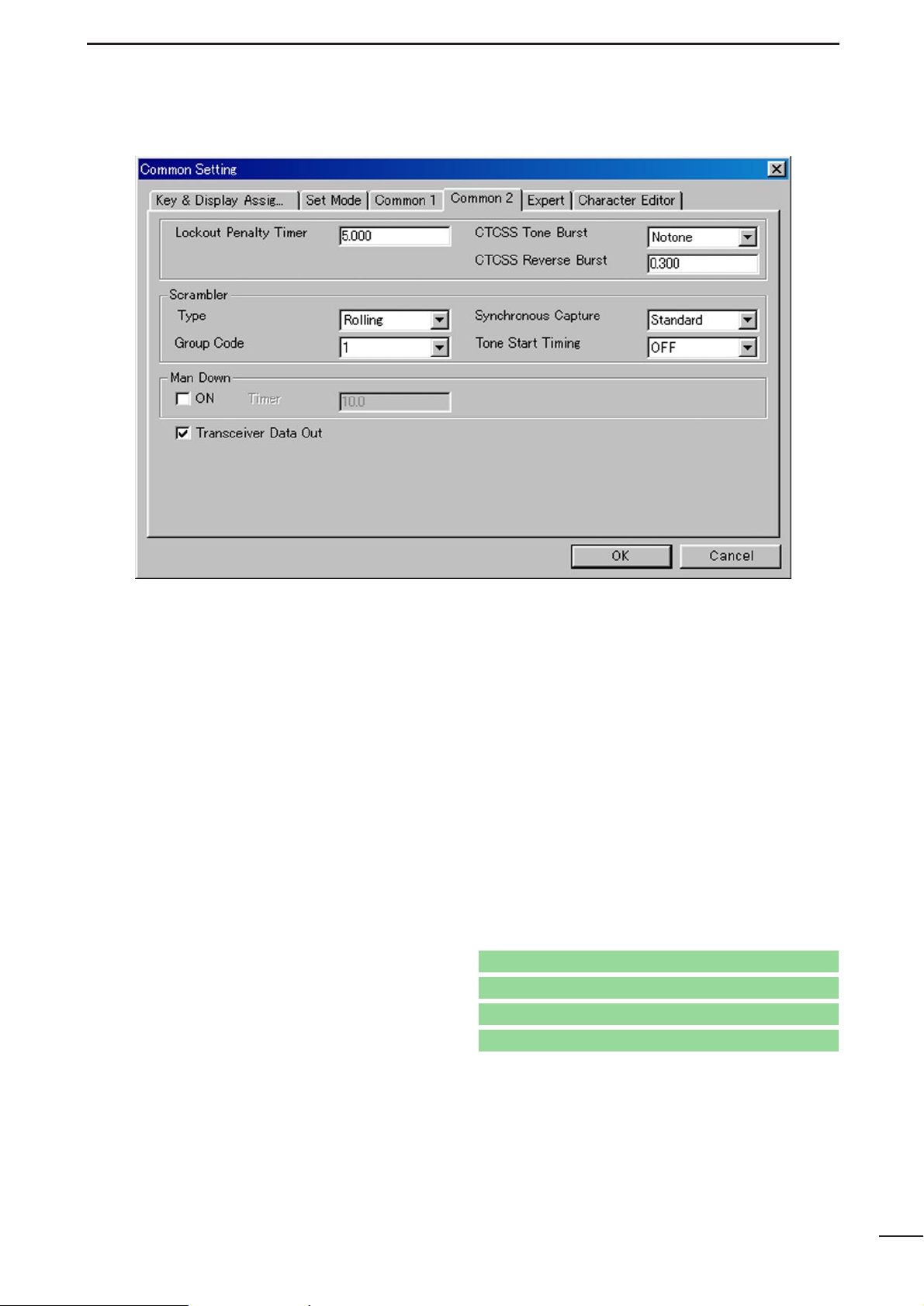
3-4 COMMON 2
• Lockout Penalty Timer
Enters the un-transmittable time period for penalty
when transmitted on a busy channel. The un-transmittable condition is kept for the programmed time
period even if the channel is cleared.
The lockout penalty time is the transmit inhibit period
when the user attempts to transmit while in a lockout
condition. The transmission is inhibited for the lockout penalty time even when the lockout condition is
cleared.
• CTCSS Tone Burst
Selects the tone burst system from Notone and
Phase.
Notone: Unmodulates CTCSS encoder signal for
the specified time period programmed in
CTCSS Reverse Burst in this screen, as at
right. (This system is currently used.)
Phase : Reverses the phase of CTCSS encoder
signal for the specified time period pro-
grammed in CTCSS Reverse Burst in this
screen, as at right.
• CTCSS Reverse Burst
Enters the time period for transmission delay with
[PTT] switch operation and CTCSS signal.
The transceiver still transmits for the programmed
period without the CTCSS encoder, or with phase
reversed CTCSS encoder signal, after [PTT] is
released. This removes the transceiver’s ‘Squelch
delay’.
• CTCSS Reverse Burst
Tone output
ON
OFF
RF power
output
ON
OFF
Time
PTT action
ON
OFF
CTCSS Reverse Burst
Page 21
19
COMMON SETTING
3
3-4 COMMON 2— Continued
• Scrambler— Type
Selects the scrambler type from Rolling and Non-Rolling.
Selects ‘Rolling’ when the optional voice scrambler
unit, UT-110 (#02), is installed, selects ‘Non-Rolling’
when UT-109 is installed.
UT-110 and UT-109 are not compatible due to different scrambling systems. However, UT-110 can be
used instead of UT-109 by selecting ‘Non-Rolling’
type in this item
The Scrambler— Group Code as follows, must be pro-
grammed when UT-110 is used with the Rolling setting.
• Scrambler— Synchronous Capture
Selects the synchronous capture mode from
Standard and Continuous.
It is recommended that ‘Standard’is selected for simplex/normal operation, ‘Continuous’ for repeater
operation.
• Scrambler— Group Code
Selects the scrambler group code from 1, 2, 3 and 4
when the optional voice scrambler unit, UT-110 (#02),
is installed and ‘Rolling’ is selected in the
Scrambler— Type as above.
Programming is not required when the optional voice
scrambler unit, UT-109, is installed.
• Scrambler— Tone Start Timing
Selects the reference tone signal delay time from
OFF, 0.3sec., 0.6 sec. and 1.1 sec.
The setting is used to synchronize voice scrambling
timing when the other stations/transceivers are in
power save mode.
• Man Down— ON, Timer
Click the check-box, ON, and enter time period in the
Timer column (25.5 sec. max.) to activate the man
down function when the optional UT-113 MAN DOWN
UNIT
is installed.
The transceiver selects emergency channel and
transmits an emergency signal automatically after
passing the programmed time period when the transceiver has been left in a horizontal position.
The emergency channel is programmed in CH Atr in
4/5 MEMORY CHANNEL
(LMR; p. 23/PMR; p. 29).
For the emergency signal—
LMR : DTMF code of Emergency, programmed in
6-
1 DTMF AUTODIAL
(p. 40), is used.
PMR :
Specified 5-tone/DTMF code selected in
5Tone Signaling— STN in
5 MEMORY
CHANNEL
(p. 34) of the emergency channel.
• Transceiver Data Out
Click the check-box to enable the transceiver’s programmed data out capability for both using this software and cloning between transceivers.
-The “✔” mark appears in the check-box when checked.
The setting does not inhibit data writing, therefore
over writing data is still possible even when not
checked.
Go to CH Atr— LMR
Go to CH Atr— PMR
Go to 6-1 DTMF AUTODIAL
Go to 5Tone Signaling— STN
Page 22
20
COMMON SETTING
3
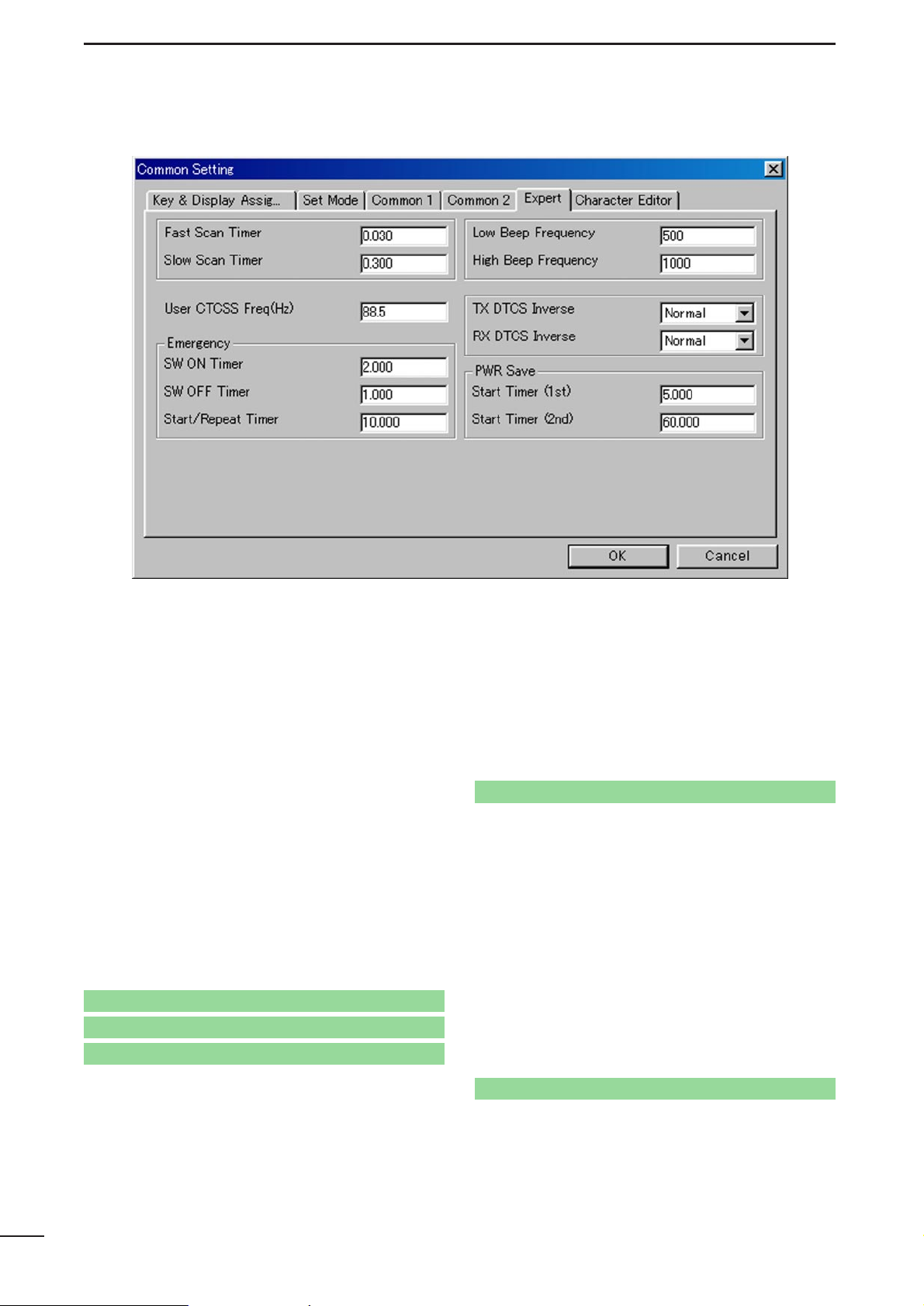
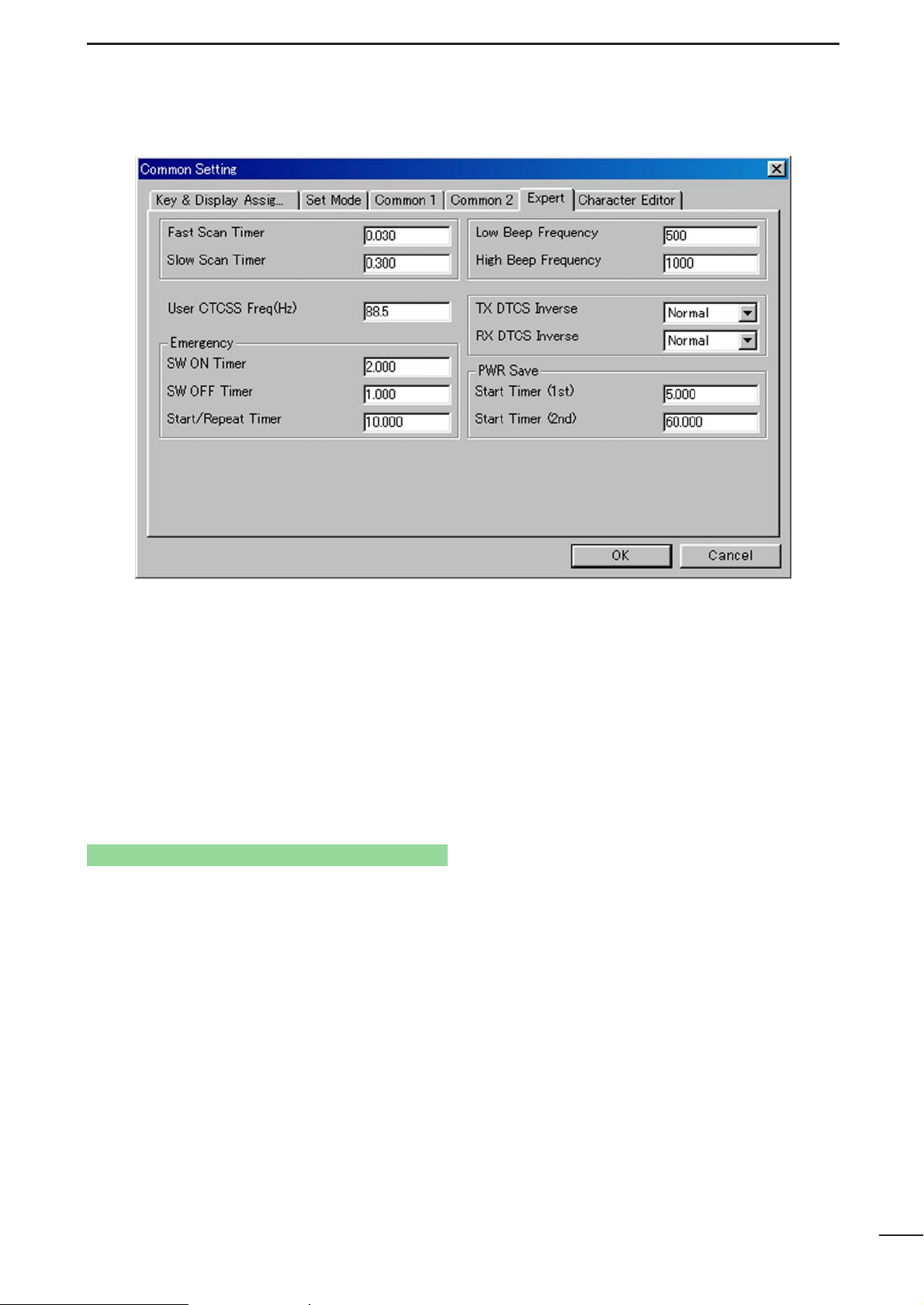
3-5 EXPERT
• Fast Scan Timer
Enters the time period for scanning of each channel
without CTCSS/DTCS programming.
An appropriate time is set by default and scan may
not stop when setting a value less than the default.
• Slow Scan Timer
Enters the time period for scanning of each channel
with CTCSS/DTCS programming.
An appropriate time is set by default and scan may
not stop when setting a value less than the default.
• User CTCSS Freq(Hz)
Programs additional customer/system own CTCSS
frequency to the existing 51 CTCSS frequencies
within 60.1 to 300.1 Hz range.
The programmed CTCSS frequency can be selected
in C.Tone— RX and TX in
4/5 MEMORY CHANNEL
(LMR; p. 25/PMR; p. 31), and RX, TX in
7 CONTINU-
OUS TONE
(p. 42) by selecting ‘USER’.
• Emergency— SW ON Timer
Enters time period for which [Emergency Repeat] or
[Emergency Single] switch must be held to activate
the emergency function.
Push and hold [Emergency Repeat] or [Emergency
Single] switch for the programmed time period to
make an emergency call.
[Emergency Repeat] or [Emergency Single] switch is
assigned in
3-1 KEY & DISPLAYASSIGN
(p. 9).
• Emergency— SW OFF Timer
Enters time period for which [Emergency Repeat] or
[Emergency Single] switch must be held to cancel
the emergency function.
Push and hold [Emergency Repeat] or [Emergency
Single] switch for the programmed time period to
cancel an emergency call before an emergency signal is transmitted.
However, once an emergency call is transmitted, the
call cannot be cancelled regardless of this setting.
[Emergency Repeat] or [Emergency Single] switch is
assigned in
3-1 KEY & DISPLAYASSIGN
(p. 9).
Go to Emergency Repeat, Emergency Single
Go to Emergency Repeat, Emergency Single
Go to C.Tone— RX and TX— LMR
Go to C.Tone— RX and TX— PMR
Go to RX, TX
Page 23
21
COMMON SETTING
3
3-5 EXPERT— continued
• Emergency— Start/Repeat Timer
Enter the time periods for the emergency call delay
and interval.
The transceiver makes an emergency call after passing the programmed time period when the emergency function is activated.
The transceiver transmits an emergency signal
repeatedly at this interval until an “Emergency
Cancel” code is received when [Emergency Repeat]
is used.
[Emergency Repeat] or [Emergency Single] switch is
assigned in
3-1 KEY & DISPLAYASSIGN
(p. 9).
• Low Beep Frequency, High Beep Frequency
Enter the beep audio frequency for each Low (for
error)
and High (for regular) beep within 400 to 2998
Hz range, respectively.
The nearest available frequency is selected automatically.
• TX DTCS Inverse
Selects the transmit DTCS code polarity.
In order for the transceiver to communicate using a
DTCS code, the polarity of the transmitting transceiver’s transmit code must be the same as the
polarity of the receiving transceiver’s receive code.
• RX DTCS Inverse
Selects the receive DTCS code polarity.
In order for transceivers to communicate using
DTCS codes, the polarity of the receiving transceiver’s receive code must be the same as the polarity of
the transmitting transceiver’s transmit code.
• PWR Save— Start Timer (1st), (2nd)
Enter the time period for the power saver function
start timers within 0–25.5 sec. for the 1st, and 1–255
sec. or OFF (enter ‘OFF’, when ‘OFF’ is selected) for the
2nd timer.
The 1st timer must be set smaller than the 2nd timer,
due to the fact that the 2nd timer/power saver function activates after the 1st timer/power saver.
Otherwise the 1st timer does not activate. The 2nd
timer will be set to ‘OFF’ when the UT-110 voice
scrambler unit is installed. The long timer setting will
be invalid.
Go to Emergency Repeat, Emergency Single
Page 24

22
COMMON SETTING
3
3-6 CHARACTER EDITOR
Up to 16 original characters or symbols can be edited/created in this sheet for a variety of information
indication.
• Thumbnail A–P
Shows created original character or symbol.
The characters or symbols are displayed on the LCD
when they are programmed in Opening Text in
3-1
KEY & DISPLAY ASSIGN
(p. 13), Text in
4/5 MEM-
ORY CHANNEL
(LMR; p. 24/PMR; p. 30),
6-1 DTMF
AUTODIAL
(p. 40),
8-1 SCAN LIST
(p. 43),
9-1/10-1
RX CODE CHANNEL
(2-tone; p. 45/5-tone; p. 49) or
10-2 TX CODE CHANNEL
(p. 52).
• Character Edit Map
Original character editing image map.
The edited characters are shown in the thumbnails
A–P, respectively.
Character editing instructions are as follows.
q Select a character thumbnail from A–P to be edit-
ed with mouse operation.
w Click desired segment boxes/dots on the map with
the mouse pointer.
- Clicked segment boxes/dots become black.
- To cancel, click unwanted black segment
boxes/dots again.
e Click [OK] button in this screen, or click on other
character thumbnail if programming more characters.
- Common Setting screen will be closed after [OK]
button is clicked.
Go to Opening Text
Go to Text— LMR
Go to Text— PMR
Go to Text— 6-1 DTMF AUTODIAL
Go to Text— 8-1 SCAN LIST
Go to Text— 9-1 RX CODE CHANNEL
Go to Text— 10-1 RX CODE CHANNEL
Go to Text— 10-2 TX CODE CHANNEL
Page 25

MEMORY CHANNEL— LMR
4
23
• CH Atr
Selects the channel attribution from Prio A, Prio B,
Emergency, Emergency OFF and SmarTrunk
ON/OFF.
Right click on the desired
channel to open the submenu window as at right,
then select the channel
attribution.
A: Priority— “A” tagged channel becomes the pri-
ority channel A, simply recalled by pushing
[Priority A] or [Priority A (Rewrite)] switch and
also is automatically monitored during the priority scan. When [Priority A (Rewrite)] switch is
assigned, priority channel Acan be re-assigned
by pushing [Priority A (Rewrite)] switch for
1 sec.
B: Priority— “B” tagged channel becomes the pri-
ority channel B, simply recalled by pushing
[Priority B] switch.
E: Emergency— “E” tagged channel becomes an
emergency channel, immediately recalled and
sends an emergency signal by pushing
[Emergency Single] or [Emergency Repeat]
switch, or when the man down function is activated. Only 1 channel can be set.
Emergency OFF— Regular channel.
SmarTrunk ON/OFF— Specifies the selected
bank for SmarTrunk operation.
SmarTrunk specified bank/s, the bank item in the
Memory Channel folder, displayed in the T ree View
Screen, changes from regular to SmarTrunk type
as follows, for easy recognition.
: Regular type : SmarTrunk type
[Priority A], [Priority A (Rewrite)], [Priority B],
[Emergency Single] and [Emergency Repeat] switches
are assigned in
3-1 KEY & DISPLAY ASSIGN
(pgs. 7, 9).
The man down function is specified in Man Down—
ON, Timer in
3-4 COMMON 2
(p. 19).
The channel attribution can only be set on the
Memory Channel Screen as shown above. (Cannot
be set in the Edit window.) However, the other items
are programmable in the Edit window only.
The Edit window appears by pushing the [Enter] key,
double clicking or selecting in the sub menu window
via right click operation with the mouse on the
desired channel.
Go to Emergency Single, Emergency Repeat
Go to Prio A (Rewrite)
Go to Prio A, Prio B
Go to w Memory Channel
Go to Man Down— ON, Timer
Page 26

24
MEMORY CHANNEL— LMR
4
• Frequency— RX, TX
Enter receive and transmit frequencies within the following frequency ranges in either 5, 6.25 or 7.5 kHz
steps* for the RX and TX boxes, respectively.
IC-F30GT/GS : 136–174 MHz
IC-F40GT/GS* : 400–430, 440–480, 450–490,
480–512, 480–520 MHz
*according to version
When no receive frequency is entered, other items
cannot be programmed in the channel.
When SmarTrunk ON/OFF is selected for the editing bank in CH Atr (p. 23), operating frequencies
must be programmed from channel 1 without a
blank.
When programming a simplex channel (transmit and
receive frequencies are the same), checks the simplex check-box for instant setting after receive frequency is programmed as follows.
• Frequency— Simplex
Click the check-box when the same frequency as the
receive is used for the transmit.
-The “✔” mark appears in the check-box when checked.
• Frequency— Text
Enter up to a 12-character text in the Text box for
memory name, channel usage, etc.
The usable characters are A–Z, a–z, 0–9, $, ’, (, ), –,
/, <, =, >, @, [, \, ], _, {, |, } ~ and user original characters.
When entering user original characters, enter ‘%’and
the desired thumbnail number A to P (capital letter
only).
Programming example.:
When entering original character’s thumbnail number C, enter as ‘%C.’
When no text is entered, the channel number is indicated.
User original characters are programmed in
3-6
CHARACTER EDITOR
(p. 22).
• Frequency— CH Inhibit
Click the check-box when the channel is to be inhibited.
The channel never appears on the transceiver, even
if all the other items are programmed when the channel is inhibited.
-The “✔” mark appears in the check-box when checked.
• Frequency— TX Inhibit
Click the check-box when transmission inhibit is necessary .
-The “✔” mark appears in the check-box when checked.
Go to CH Atr
Go to 3-6 CHARACTER EDITOR
Page 27

25
MEMORY CHANNEL— LMR
4
• 2Tone
Selects the 2-Tone code channel for reception with
transceiver’s action when a matched 2-tone code is
received from OFF, 1, 2 and 3.
OFF : Nothing changes.
1, 2, 3 : Activates a specified channel 1, 2 or 3 as
programmed in the
9-1 RX CODE CHAN-
NEL
(p. 45).
• C.Tone— RX, TX
Selects
the
desired CTCSS frequency from the list or
enter a 3-digit DTCS code with polarity,
N (Normal) or
I (Inverse),
for receive and transmit in the RX and TX
boxes,
respectively.
RECOMMENDATION
When programming a CTCSS/DTCS code, choosing a frequency/code, listed in the following tables
is recommended. In case a CTCSS
frequency/DTCS code other than below is used,
sometimes the squelch system may not performed
correctly .
• C.Tone— RX, TX— continue
When programming the same continuous tone as the
receive for the transmission, check the simplex
check-box for instant setting after receive frequency
is programmed as follows.
• C.Tone— Simplex
Click the check-box when the same continuous tone
as the receive is used for the transmission.
-The “✔” mark appears in the check-box when checked.
• Scan— 1–10
Click the check-box of the channel included into the
desired scan list (scanning group) 1–10.
Only the checked channels in the same scan list are
scanned when [Scan A Start/Stop] or [Scan B
Start/Stop] switch is pushed.
-The “✔” mark appears in the check-box when checked.
The scan list (scanning group) is selectable via
[CH Up] or [CH Down] switches, after [Scan A
Start/Stop] or [Scan B Start/Stop] switch is pushed
for 1 sec.
The scanning conditions for each scan list are specified in
8 SCAN LIST
(pgs. 43–44).
When SmarTrunk ON/OFF is selected for the editing bank in CH Atr (p. 23), all boxes must be blank.
[CH Up], [CH Down], [Scan A Start/Stop] or [Scan B
Start/Stop] switch is assigned in
3-1 KEY & DIS-
PLAY ASSIGN
(p. 6).
Go to 8 SCAN LIST
Go to CH Atr
Go to CH Up, CH Down
Go to Scan A Start/Stop, Scan B Start/Stop
67.0
69.3
71.9
74.4
88.5
91.5
94.8
97.4
114.8
118.8
123.0
127.3
151.4
156.7
162.2
167.9
203.5
210.7
218.1
225.7
77.0
79.7
82.5
85.4
100.0
103.5
107.2
110.9
131.8
136.5
141.3
146.2
173.8
179.9
186.2
192.8
233.6
241.8
250.3
• Recommended CTCSS frequencies
023
025
026
031
032
043
047
051
054
065
071
072
073
074
114
115
116
125
131
132
134
143
152
155
156
162
165
172
174
205
223
226
243
244
245
251
261
263
265
271
306
311
315
331
343
346
351
364
365
371
411
412
413
423
431
432
445
464
465
466
503
506
516
532
546
565
606
612
624
627
631
632
654
662
664
703
712
723
731
732
734
743
754
• Recommended DTCS codes
Go to 9-1 RX CODE CHANNEL
Page 28

26
MEMORY CHANNEL— LMR
4
• Scan— Scan List Include
Click the check-box to enable scanning channel
modification from the transceiver’s keypad.
The desired channel can be added or deleted to/from
the selected scan list by pushing [Scan Add/Del(Tag)]
switch.
[Scan Add/Del(Tag)] switch is assigned in
3-1 KEY &
DISPLAY ASSIGN
(p. 6).
• Scrambler— OFF, ON, Inhibit
Click to select voice scrambling function initial setting
from OFF, ON and Inhibit.
When OFF or ON is selected, the voice scrambling
function can be manually switched with the
[Scrambler] switch, however, the function cannot be
manually switched ON when Inhibit is selected.
An optional UT-109 or UT-110 VOICE SCRAMBLER UNIT
is required.
The [Scrambler] switch is assigned in
3-1 KEY &
DISPLAY ASSIGN
(p. 10).
• Scrambler— Code
Enter the voice scrambling code within 1–32 using
UT-109 or UT-110 with ‘Non-Rolling’ selection or
within 1–255 using UT-110 with ‘Rolling’ selection
installed.
In addition, the Scrambler— Group Code in
3-4
COMMON 2
(p. 19) must be programmed when UT-
110 is installed and ‘Rolling’ is selected in
Scrambler— Type in
3-4 COMMON 2
(p. 19).
• Wide/Narrow
Select the passband width for each operating channel from Wide and Narrow.
The selection can be manually switched with the
[Wide/Narrow] switch for temporary operation.
The [Wide/Narrow] switch is assigned in 3-1
KEY &
DISPLAY ASSIGN
(p. 8).
• RF PWR
Selects the transmit output power for initial setting
from High, Low1 and Low2.
The selected output power setting for each channel
can be switched to either temporary or permanent
operation, according to the setting in the RF Power
Selection in
3-1 KEY & DISPLAY ASSIGN
(p. 13) via
[High/Low] switch.
The [High/Low] switch is assigned in the
3-1 KEY &
DISPLAY ASSIGN
(p. 7)
Go to RF Power Selection
Go to High/Low
Go to Scrambler
Go to Scrambler— Group Code
Go to Scrambler— Type
Go to Wide/Narrow
Go to Scan Add/Del(Tag)
Page 29

• Lock out
Selects the transmission lock out (temporary transmis-
sion inhibit)
capability from OFF, Busy and Rpt
(Repeater).
OFF : No restriction for receiving a signal.
Busy : [PTT] switch cannot be activated while the
operating channel/repeater is in use.
Rpt : [PTT] switch can be activated while receiv-
ing a signal with matched CTCSS (or
DTCS) tone or no signals.
In addition, [PTT] switch is not activated for an extra
time period in the case of when the lockout penalty
timer, programmed in the Lockout Penalty Timer in
3-4 COMMON 2
(p. 18), is activated, even if the
transceiver is in a transmittable condition.
• Log IN/OFF
Selects the automatic ID transmission condition in
relation with [PTT] from L-IN, L-OFF, Both and OFF.
OFF : No ID is transmitted with [PTT].
L-IN : ID is transmitted each time [PTT] is pushed.
L-OFF: ID is transmitted each time [PTT] is
released.
Both : ID is transmitted each time [PTT] is pushed
and released.
Log/ID code is used as the ID code, programmed in
6-1 DTMF AUTODIAL
(p. 40).
When SmarTrunk ON/OFF is selected for the editing bank in CH Atr (p. 23), “OFF” must be selected.
• Auto Reset
Selects the reset timer from Timer Aand Timer B for
restarting scanning when the power ON scan function is activated
Timer A, Timer B:
Restarts scanning after specified time period
(Timer Aor Timer B) has passed from a disap-
pearing signal or key operation is finished.
The time period of Timer A and Timer B are programmed in the Auto Reset Timer A, Auto Reset
Timer B in
3-3 COMMON 1
(p. 16), respectively.
To turn OFF the function, select the timer in which
OFF (0 sec.) is programmed.
The power ON scan function is specified in the
Power ON Scan in
8-2 SCAN SETTING
(p. 44).
• Compander
Click the check-box to activate the compander function.
-The “✔” mark appears when the compander function is
activated.
When communicating with other station which
doesn’t use or have the compander function, recommend to turn the compander function OFF via
[Compander] switch or not click the check-box.
The function can be switched ON or OFF for temporary operation with the [Compander] switch.
The [Compander] switch is assigned in
3-1 KEY &
DISPLAY ASSIGN
(p. 10).
MEMORY CHANNEL— LMR
4
27
Go to Lockout Penalty Timer
Go to CH Atr
Go to 6-1 DTMF AUTODIAL
Go to Power ON Scan
Go to Auto Reset Timer A, Auto Reset Timer B
Go to Compander
Page 30

28
MEMORY CHANNEL— LMR
4
•TOT
Click the check-box to activate the time-out timer
function.
-The “✔” mark appears when TOT function is activated.
Continuously transmittable time is limited by the timer
during activation. However, time-out timer must be
activated due to local regulation in some countries.
The time period is programmed in the TOT— TOT
Timer in
3-3 COMMON 1
(p. 17).
When SmarTrunk ON/OFF is selected for the editing bank in CH Atr (p. 23), “OFF” must be selected.
• PWR Save
Click the check-box to activate the power save function.
-The “✔” mark appears when the power save function is
activated.
The power save start times are programmed in the
PWR Save— Start Timer (1st), (2nd) in
3-5
EXPERT
(p. 21).
When SmarTrunk ON/OFF is selected for the editing bank in CH Atr (p. 23), “OFF” must be selected.
Go to CH Atr
Go to TOT— TOT Timer
Go to CH Atr
Go to PWR Save— Start Timer (1st), (2nd)
Page 31

MEMORY CHANNEL— PMR
5
29
• CH Atr
Selects the channel attribution from Prio A, Prio B,
Emergency, Emergency OFF and SmarTrunk
ON/OFF.
Right click on the desired
channel to open the submenu window as at right,
then select the channel
attribution.
A: Priority— “A” tagged channel becomes the pri-
ority channel A, simply recalled by pushing
[Priority A] or [Priority A (Rewrite)] switch, and
also is automatically monitored during the priority scan. When [Priority A (Rewrite)] switch is
assigned, priority channel Acan be re-assigned
by pushing [Priority A (Rewrite)] switch for
1 sec.
B: Priority— “B” tagged channel becomes the pri-
ority channel B, simply recalled by pushing
[Priority B] switch.
E: Emergency— “E” tagged channel becomes an
emergency channel, immediately recalled and
sends an emergency signal by pushing
[Emergency Single] or [Emergency Repeat]
switch, or when the man down function is acti-
vated. Only 1 channel can be set.
Emergency OFF— Regular channel.
SmarTrunk ON/OFF—
Specifies the selected bank
for SmarTrunk operation.
SmarTrunk specified bank/s, the bank item in the
Memory Channel folder, displayed in the T ree View
Screen, changes from regular to SmarTrunk type
as follows, for easy recognition.
: Regular type : SmarTrunk type
[Priority A], [Priority A (Rewrite)], [Priority B],
[Emergency Single] and [Emergency Repeat] switches
are assigned in
3-1 KEY & DISPLAY ASSIGN
(pgs. 7, 9).
The man down function is specified in Man Down—
ON, Timer in
3-4 COMMON 2
(p. 19).
The channel attribution can only be set on the
Memory channel Screen as shown above. (Cannot
be set in the Edit window.) However, the other items
are programmable in the Edit window only.
The Edit window appears by pushing the [Enter] key,
double clicking or selecting in the sub menu window
via right click operation with the mouse on the
desired channel.
Go to Emergency Single, Emergency Repeat
Go to Prio A (Rewrite)
Go to Prio A, Prio B
Go to w Memory Channel
Go to Man Down— ON, Timer
Page 32

30
SCREEN MENU OPERATION— PMR
5
• Frequency— RX, TX
Enter receive and transmit frequencies within the following frequency ranges in either 5, 6.25 or 7.5 kHz
steps* for the RX and TX boxes, respectively.
IC-F31GT/GS : 136–174 MHz
IC-F41GT/GS : 400–430, 440–480, 470–500,
490–520 MHz
*according to version
When no receive frequency is entered, other items
cannot be programmed in the channel.
When SmarTrunk ON/OFF is selected for the editing bank in CH Atr (p. 29), operating frequencies
must be programmed from channel 1 without a
blank.
When programming a simplex channel (transmit and
receive frequencies are the same), checks the simplex check-box for instant setting after receive frequency is programmed as follows.
• Frequency— Simplex
Click the check-box when the same frequency as the
receive is used for the transmit.
-The “✔” mark appears in the check-box when checked.
• Frequency— Text
Enter up to a 12-character text in the Text box for
memory name, channel usage, etc.
The usable characters are A–Z, a–z, 0–9, $, ’, (, ), –,
/, <, =, >, @, [, \, ], _, {, |, } ~ and user original characters.
When no text is entered, the channel number is indicated.
When entering user original characters, enter ‘%’and
the desired thumbnail number A to P (capital letter
only)
.
Programming example:
When entering original character’s thumbnail number C, enter as ‘%C.’
User original characters are programmed in
3-6
CHARACTER EDITOR
(p. 22).
• Frequency— CH Inhibit
Click the check-box when the channel is to be inhibited.
The channel never appears on the transceiver, even
if all the other items are programmed when the channel is inhibited.
-The “✔” mark appears in the check-box when checked.
Go to CH Atr
Go to 3-6 CHARACTER EDITOR
Page 33

31
SCREEN MENU OPERATION— PMR
5
• Frequency— TX Inhibit
Click the check-box when transmission inhibit is necessary .
-The “✔” mark appears in the check-box when checked.
• C.Tone— RX, TX
Selects a desired CTCSS frequency from the list or
enter a 3-digit DTCS code with polarity,
N (Normal) or
I (Inverse),
for receive and transmit in the RX and TX
boxes,
respectively.
RECOMMENDATION
When programming a CTCSS/DTCS code, choosing a frequency/code, listed in the following tables is
recommended. In case a CTCSS frequency/DTCS
code other than below is used, sometimes the
squelch system may not performed correctly.
• C.Tone— Simplex
Click the check-box when the same continuous tone
as the receive is used for the transmission.
-The “✔” mark appears in the check-box when checked.
• Scan— 1–10
Click the check-box of the channel included into the
desired scan list (scan group) 1–10.
Only the checked channels in the same scan list are
scanned when [Scan A] or [Scan B] switch is
pushed.
-The “✔” mark appears in the check-box when checked.
The scan list (scanning group) is selectable via
[CH Up] or [CH Down] switches, after [Scan A] or
[Scan B] switch is pushed for 1 sec.
The scanning conditions for each scan list are specified in
8 SCAN LIST
(pgs. 43–44).
When SmarTrunk ON/OFF is selected for the editing bank in CH Atr (p. 29), all boxes must be blank.
[CH Up], [CH Down], [Scan A Start/Stop] or [Scan B
Start/Stop] switch is assigned in
3-1 KEY & DIS-
PLAY ASSIGN
(p. 6).
Go to 8 SCAN LIST
Go to CH Atr
Go CH Up, CH Down
Go to Scan A Start/Stop, Scan B Start/Stop
67.0
69.3
71.9
74.4
88.5
91.5
94.8
97.4
114.8
118.8
123.0
127.3
151.4
156.7
162.2
167.9
203.5
210.7
218.1
225.7
77.0
79.7
82.5
85.4
100.0
103.5
107.2
110.9
131.8
136.5
141.3
146.2
173.8
179.9
186.2
192.8
233.6
241.8
250.3
• Recommended CTCSS frequencies
023
025
026
031
032
043
047
051
054
065
071
072
073
074
114
115
116
125
131
132
134
143
152
155
156
162
165
172
174
205
223
226
243
244
245
251
261
263
265
271
306
311
315
331
343
346
351
364
365
371
411
412
413
423
431
432
445
464
465
466
503
506
516
532
546
565
606
612
624
627
631
632
654
662
664
703
712
723
731
732
734
743
754
• Recommended DTCS codes
Page 34

• Scan— Scan List Include
Click the check-box to enable scanning channel
modification from the transceiver’s key.
The desired channel can be added or deleted to/from
the selected scan list by pushing [Scan Add/Del(Tag)]
switch.
[Scan Add/Del(Tag)] switch is assigned in
3-1 KEY &
DISPLA YASSIGN
(p. 6).
• SW Action— Moni
Selects [Moni(Audi)] switch action from OFF, Aud,
In A, In A+R1, In A+R2, Both, Both+R1 and
Both+R2.
OFF : Releases both noise and CTCSS/DTCS
squelch mute while pushing and holding
[Moni(Audi)] switch. There is no audio output when 5-tone mute is activated on the
channel.
Aud : Releases the 5-tone mute only when ‘SGL’
is selected in CH Mute (p. 38) in this screen,
by pushing [Moni(Audi)] switch for 1 sec.
Both CTCSS/DTCS and noise squelch
mutes are released (audio is emitted) while
pushing and holding [Moni(Audi)] switch
when 5-tone mute is released or ‘CONT’ is
selected in CH Mute (p. 38) in this screen.
• SW Action— Moni— continued
In A : Mutes the 5-tones when ‘SGL’ is selected in
CH Mute (p. 38) in this screen by pushing
[Moni(Audi)] switch.
Both CTCSS/DTCS and noise squelch
mutes are released (audio is emitted) while
pushing and holding [Moni(Audi)] switch
while 5-tone mute is activated.
In A+R1, In A+R2:
In addition to the ‘In_A’ condition as above,
a reset code 1 or 2 is automatically transmitted when call transmission is performed
or 5-tone mute is activated by pushing
[Moni(Audi)] switch.
Both : Mutes the 5-tones when ‘SGL’is selected in
CH Mute (p. 38) in this screen by pushing
[Moni(Audi)] switch.
Releases 5-tone mute when ‘SGL’is selected in CH Mute (p. 38) in this screen by
pushing [Moni(Audi)] switch for 1 sec.
Releases all mute controls and emits audio
while pushing and holding [Moni(Audi)]
switch.
32
SCREEN MENU OPERATION— PMR
5
Go to Scan Add/Del(Tag)
Page 35

SCREEN MENU OPERATION— PMR
33
5
• SW Action— Moni (continued)
Both+R1, Both+R2:
In addition to the ‘Both’ condition as above,
a reset code 1 or 2 is automatically transmitted when call transmission is performed
via [Call] switch or 5-tone mute is activated
by pushing [Moni(Audi)] switch.
The [Moni(Audi)] and [Call] switches are assigned in
the
3-1 KEY & DISPLAYASSIGN
(pgs. 7, 8).
The reset code 1 and 2 are programmed in
10-2 TX
CODE CHANNEL
(p. 52), and channels 32 (reset
code 1)
and 31 (reset code 2) are used, respectively.
The mute condition will be returned to initial condition
when the Auto Reset timer is activated, specified in
Auto Reset in this screen (p. 37).
• SW Action— Sel
Selects the mute condition after memory or TX code
channel selection from OFF, Aud and In A.
OFF : Does not change even when selecting
memory or TX code channel.
Aud :
Releases the 5-tone mute when ‘SGL’ is
selected in CH Mute (p. 38) in this screen.
In A : Mutes the 5-tones when ‘SGL’is selected
in CH Mute (p. 38) in this screen.
The mute condition will be returned to initial condition
when the Auto Reset timer is activated, specified in
Auto Reset in this screen (p. 37).
Go to CH Mute
Go to Auto Reset
Go to CH Mute
Go to Moni(Audi)
Go to Call
Go to 10-2 TX CODE CHANNEL
Go to Auto Reset
Page 36

• SW Action— Call, PTT
Selects the mute condition after [Call] and [PTT]
switches action from Aud and OFF.
OFF : Does not change when transmitting with
[Call]/[PTT] transmission.
Aud : Releases the 5-tone mute when ‘SGL’ is
selected in CH Mute (p. 38) in this screen
after any [Call]/[PTT] transmission.
Select OFF for both the SW Action— Call and PTT,
when the ABC— Aud in
10-2 TX CODE CHANNEL
(p. 53) is activated, and select OFF for the SW
Action— PTT, when the PTT Call at Inaudible in
10-
5 5TONE SETTING
(p. 57) is activated.
The [Call] switch is assigned in the
3-1 KEY & DIS-
PLAY ASSIGN
(p. 8).
The mute condition will be returned to initial condition
when the Auto Reset timer is activated, specified in
Auto Reset in this screen (p. 37).
• 5Tone Signaling— Form
Selects 5-tone system format from USER, CCIR, ZVEI1,
ZVEI2, DZVEI, EEA, EEA2, DAPL, EIA and DTMF.
When the DTMF decoder operation is required,
select DTMF in this item.
• 5Tone Signaling— RPT, STN, ID
Selects 5-tone code channel for repeater (RPT), individual station/group (STN) access and own identity
(ID), respectively.
These 5-tone codes are programmed in TX Code in
10-2 TX-CODE CHANNEL
(p. 52).
34
SCREEN MENU OPERATION— PMR
5
Go to TX Code
Go to CH Mute
Go to Go to ABC— Aud
Go to Call
Go to PTT Call at Inaudible
Go to Auto Reset
Page 37

35
SCREEN MENU OPERATION— PMR
5
• 5Tone Signaling— Pos
Selects the own ID code sending sequence from
OFF, BTM and TOP.
OFF : Does not send the ID code.
BTM : Sends the ID code after sending station or
group code.
TOP : Sends the ID code before sending station
or group code.
• 5Tone Signaling— Long
Click the check-box to activate the long tone capability for each 5-tone code, RPT, STN and ID, respectively.
-The “✔” mark appears when long tone is activated.
The time period for the long tone is programmed in
the Long Tone Timer in
10-5 5TONE SETTING
(p. 56).
• RX C-No
Click the check-box to select the receive 5-tone code
channel to be decoded.
Up to 8 codes/channels can be selected to decode in
each operating channel.
The 5-tone code is programmed in RX Code in
10-1
RX CODE CHANNEL
(p. 49).
• Wide/Narrow
Select the passband width for each operating channel from Wide and Narrow.
The selection can be manually switched with the
[Wide/Narrow] switch for temporary operation.
The [Wide/Narrow] switch is assigned in 3-1
KEY &
DISPLAY ASSIGN
(p. 8).
Go to Long Tone Timer
Go to RX Code
Go to Wide/Narrow
• ID code sending sequence diagram
TOP
Time
BTM
1 2 3 4 5 1 2 3 4 5 1 2 3 4 5
Repeater code
(if available)
Station/Group
code
ID code
1 2 3 4 5 1 2 3 4 5 1 2 3 4 5
Repeater code
(if available)
ID code
Station/Group
code
Page 38

• RF PWR
Selects the transmit output power for initial setting
from High and Low.
The selected output power setting for each channel
can be switched to either temporary or permanent
operation, according to the setting in the RF Power
Selection in
3-1 KEY & DISPLAY ASSIGN
(p. 13) via
[High/Low] switch.
The [High/Low] switch is assigned in the
3-1 KEY &
DISPLAY ASSIGN
(p. 7).
• Lock out
Selects the transmission lock out (temporary transmis-
sion inhibit)
capability from OFF, Busy, Rpt 1 and
Rpt 2.
OFF : No restriction for receiving a signal.
Busy : [PTT] switch cannot be activated while the
operating channel/repeater is in use.
Rpt1 : [PTT] switch can be activated while receiv-
ing a signal with matched CTCSS (or
DTCS) tone or no signals.
• Lock out— continued
Rpt2 : [PTT] switch can be activated while receiv-
ing a signal with matched CTCSS (or
DTCS) tone or no signals while 5-tone mute
is released, or receiving an unmatched
CTCSS (or DTCS) tone while 5-tone mute
is activated.
In addition, [PTT] switch is not activated for an extra
time period in the case of when the lockout penalty
timer, programmed in the Lockout Penalty Timer in
3-4 COMMON 2
(p. 18), is activated even if the trans-
ceiver is in a transmittable condition.
• Log IN/OFF
Selects the automatic ID transmission condition in
relation to [PTT] switch from OFF, L-IN, L-INA, L-INI,
L-OFF, L-OFFA, Both, BothA1 and BothA2.
OFF : No ID is transmitted with [PTT].
L-IN : ID is transmitted when [PTT] is pushed.
L-INA : ID is transmitted when [PTT] is pushed
while 5-tone mute is released.
L-INI : ID is transmitted when [PTT] is pushed
while 5-tone mute is activated. Voice
transmission is impossible while 5-tone
mute is activated and ‘SGL’ is selected in
CH Mute (p. 38) in this screen.
36
SCREEN MENU OPERATION— PMR
5
Go to Lockout Penalty Timer
Go to RF Power Selection
Go to High/Low
Page 39

• Log IN/OFF— continued
L-OFF : ID is transmitted when [PTT] is released.
L-OFFA : ID is transmitted when [PTT] is released
while 5-tone mute is released.
Both : ID is transmitted when both [PTT] is
pushed and released.
BothA1 : ID is transmitted when both [PTT] is
pushed and released while 5-tone mute is
released.
BothA2 : ID is transmitted when both [PTT] is
pushed and released while 5-tone mute is
released. ID is transmitted when [PTT] is
pushed while 5-tone mute is activated.
Voice transmission is impossible while 5tone mute is activated and when ‘SGL’ is
selected in CH Mute (p. 38) in this screen.
When SmarTrunk ON/OFF is selected for the editing bank in CH Atr (p. 29), “OFF” must be selected.
The ID code is assigned in the 5T one signaling— ID
column in this screen (p. 34), and the 5-tone code is
programmed in TX Code in
10-2 TX CODE CH
(p. 52).
• Auto Reset
Selects the reset timer from Timer A, Timer B, Timer
A Inact and Timer B Inact.
Timer A, Timer B:
Returns 5-tone mute condition to initial,
and
starts scanning
if power ON scan function is
tuned ON, after a specified time (Timer Aor B)
has passed from a disappearing signal, or
when key operation is finished.
Timer A Inact, Timer B Inact:
Returns 5-tone mute condition to initial after
a shorter time period (either Timer A/B or
Inactive)
has passed from when 5-tone mute
is released. Automatically returns 5-tone
mute condition to initial as soon as transmission is finished, and starts scanning after
specified time (Timer A or B) has passed.
The time period of Timer A, Timer B and Inactive
timer is programmed in the Auto Reset Timer A,
Auto Reset Timer B and Inactive Timer in
3-3
COMMON 1
(p. 16), respectively.
To turn OFF the function, select the timer which OFF
(0 sec.) is programmed.
The power ON scan function is specified in the
Power ON Scan in
8-2 SCAN SETTING
(p. 44).
37
SCREEN MENU OPERATION— PMR
5
Go to CH Atr
Go to CH Mute
Go to TX Code
Go to 5Tone Signaling— ID
Page 40

• Auto Reset— continued
5-tone mute initial condition is selected in CH Mute
as follow.
• CH Mute
Selects 5-tone mute initial activity from CONT and
SGL.
CONT :
5-tone mute
is released.
SGL :
5-tone mute
is activated. In this case, [PTT]
switch action is inhibited while 5-tone mute
is activated.
• Compander
Click the check-box to activate the compander function.
-The “✔” mark appears when the compander function is
activated.
When communicating with other station which
doesn’t use or have the compander function, recommend to turn the compander function OFF via
[Compander] switch or not click the check-box.
The function can be switched ON or OFF for temporary operation with the [Compander] switch.
The [Compander] switch is assigned in
3-1 KEY &
DISPLAY ASSIGN
(p. 10).
38
SCREEN MENU OPERATION— PMR
5
Go to Compander
Go to Inactive Timer
Go to Auto Reset Timer A, Auto Reset Timer B
Go to Power ON Scan
Page 41

•TOT
Click the check-box to activate the time-out timer
function.
-The “✔” mark appears when TOT function is activated.
Continuously transmittable time is limited by the
timer during activation. However, time-out timer must
be activated due to local regulation in some countries.
The time period is programmed in the TOT— TOT
Timer in
3-3 COMMON 1
(p. 17).
When SmarTrunk ON/OFF is selected for the editing bank in CH Atr (p. 29), “OFF” must be selected.
• PWR Save
Click the check-box to activate the power save function.
-The “✔” mark appears when the power save function is
activated.
The power save start times are programmed in the
PWR Save— Start Timer (1st), (2nd) in
3-5
EXPERT
(p. 21).
When SmarTrunk ON/OFF is selected for the editing bank in CH Atr (p. 29), “OFF” must be selected.
• Scrambler— OFF, ON, Inhibit
Click to select voice scrambling function initial setting
from OFF, ON and Inhibit.
When OFF or ON is selected, the voice scrambling
function can be manually switched with the
[Scrambler] switch, however, the function cannot be
manually switched ON when Inhibit is selected.
An optional UT-109 or UT-110 VOICE SCRAMBLER UNIT
is required.
The [Scrambler] switch is assigned in
3-1 KEY &
DISPLAY ASSIGN
(p. 10).
• Scrambler— Code
Enter the voice scrambling code within 1–32 using
UT-109 or UT-110 with ‘Non-Rolling’ selection or
within 1–255 using UT-110 with ‘Rolling’ selection
installed.
In addition, the Scrambler Group Code in
3-4 COM-
MON 2
(p. 19) must be programmed when UT-110 is
installed and ‘Rolling’ is selected in Scrambler Type
in
3-4 COMMON 2
(p. 19).
39
SCREEN MENU OPERATION— PMR
5
Go to PWR Save— Start Timer (1st), (2nd)
Go to CH Atr
Go to Scrambler
Go to TOT— TOT Timer
Go to CH Atr
Go to Scrambler Group Code
Go to Scrambler Type
Page 42

DTMF AUTODIAL
6
40
6-1 DTMF AUTODIAL
The IC-F30G series transceiver has total of 8 DTMF memory channels. The programmed DTMF codes are
selected and transmitted with simple operation. For the LMR, the programmed DTMF code in the Emergency
and the Log/ID autodial are used for Emergency call, man down function, and automatic ID transmission,
respectively.
• Code
Enter up to a 24-digit DTMF code for simple and
quick DTMF code transmission.
The usable characters are 0–9, A–F (#/✽ used as F/E).
The programmed DTMF codes are selected via
[CH Up] or [CH Down] switch after pushing [DTMF
Autodial] switch.
The [CH Up], [CH Down] and [DTMF Autodial]
switches are assigned in
3-1 KEY & DISPLAY
ASSIGN
(pgs. 6, 8).
• Text
Enter up to a 12-character text for easy recognition
of DTMF code usage, etc.
When no text is programmed, the programmed
DTMF code is scrolled.
The usable characters are A–Z, a–z, 0–9, $, ’, (, ), –,
/, <, =, >, @, [, \, ], _, {, |, } ~ and user original characters.
When entering user original characters, enter ‘%’and
the desired thumbnail number A to P (capital letter
only)
.
Programming example:
When entering original character’s thumbnail number C, enter as ‘%C.’
When no text is entered, the channel number is indicated.
User original characters are programmed in
3-6
CHARACTER EDITOR
(p. 22).
Memory Channel Screen indication for LMR
Memory Channel Screen indication for PMR
Go to CH Up, CH Down
Go to DTMF Autodial
Go to 3-6 CHARACTER EDITOR
Page 43

41
DTMF AUTODIAL
6
6-2 DTMF SETTING
• DTMF Timer
Enter the time period/signal length for each DTMF
code emission and interval.
• 1st Timer
Enter the time period/signal length for 1st DTMF
code emission and interval corresponding to the
scanning or power saving of the transceiver.
•[✽] [#] Timer
Enter the time period/signal length for [✽] and [#]
DTMF code signal emission and interval.
These codes may be used for control codes depending on the signaling system.
When these special codes are used for the 1st digit
code, the 1st Timer as at left has priority over this
setting.
Page 44

CONTINUOUS TONE
7
42
• RX, TX
Selects
the
desired CTCSS frequency from the list or
enter a 3-digit DTCS code with polarity,
N (Normal) or
I (Inverse),
for receive and transmit in the RX and TX
boxes,
respectively.
When programming the same continuous tone as the
receive for the transmission, check the simplex
check-box for instant setting after RX is programmed
as at right.
The programmed continuous tone combinations can
be used for temporary encoder and/or decoder operation.
To use the programmed continuous tone;
Push [C. Tone CH Ent] switch, then select a continuous tone memory channel via [CH Up] or
[CH Down] switch.
[C. Tone CH Ent], [CH Up] and [CH Down] switches
are assigned in
3-1 KEY & DISPLAY ASSIGN
(pgs. 6, 7).
• Simplex
Click the check-box when the same continuous tone
as the receive is used for the transmission.
-The “✔” mark appears in the check-box when checked.
RECOMMENDATION
When programming a CTCSS/DTCS code,
choosing a frequency/code, listed in the following
tables is recommended. In case a CTCSS frequency/DTCS code other than below is used,
sometimes the squelch system may not performed correctly.
Memory Channel Screen indication
Go to CH Up, CH Down
The IC-F30G series transceiver has a total of 9 continuous tone memory channels, in addition to the channel
(operating channel) independent continuous tone operation. Separate continuous tone, CTCSS or DTCS for
encoder and decoder, can be programmed for each channel, and can be operated temporarily or permanently.
Go to C.Tone CH Ent
67.0
69.3
71.9
74.4
88.5
91.5
94.8
97.4
114.8
118.8
123.0
127.3
151.4
156.7
162.2
167.9
203.5
210.7
218.1
225.7
77.0
79.7
82.5
85.4
100.0
103.5
107.2
110.9
131.8
136.5
141.3
146.2
173.8
179.9
186.2
192.8
233.6
241.8
250.3
• Recommended CTCSS frequencies
023
025
026
031
032
043
047
051
054
065
071
072
073
074
114
115
116
125
131
132
134
143
152
155
156
162
165
172
174
205
223
226
243
244
245
251
261
263
265
271
306
311
315
331
343
346
351
364
365
371
411
412
413
423
431
432
445
464
465
466
503
506
516
532
546
565
606
612
624
627
631
632
654
662
664
703
712
723
731
732
734
743
754
• Recommended DTCS codes
Page 45

SCAN LIST
8
43
8-1 SCAN LIST
A total of 10 scanning lists/groups are available for a wide variety and flexible scanning operation. In this
screen, program scanning conditions for each list/group.
• Mode
Selects the scanning mode from Scan OFF,
MODE 1, MODE 2 and MODE 3.
Scan OFF: Scan function cannot be controlled from
the transceiver keypad.
MODE 1 : Normal scan. Scans all checked chan-
nels. The scan proceeds in sequence
from lower to higher channel number.
MODE 2 : Priority scan. The priority A channel is
monitored every fixed time period during scan (depending on version), or every
specified time period programmed in
the Stop Timer in
8-2 SCAN SETTING
(p. 44), during pause. The busy or
paused channel is retained when scan
is cancelled.
MODE 3 : Priority scan. Same scanning sequence
as MODE 2 above. The priority channel
is retained when scan is cancelled.
The scanning channels are selected in Scan— 1–10
in
4/5 MEMORY CHANNEL
(LMR; p. 25/PMR; p. 31).
The priority A channel is selected in CH Atr in
4/5
MEMORY CHANNEL
(LMR; p. 23/PMR; p. 29).
• Text
Enters up to a 12-character text to indicate messages, etc. during scanning.
The usable characters are A–Z, a–z, 0–9, $, ’, (, ), –,
/, <, =, >, @, [, \, ], _, {, |, } ~ and user original characters.
When entering user original characters, enter ‘%’ and
the desired thumbnail number Ato P(capital letter only).
Programming example:
When entering original character’s thumbnail number C, enter as ‘%C.’
When no text is programmed, or “OFF” is selected
(not checked) in the Text— ON/OFF as follows, the
scanning channel text or number is scrolled.
User original characters are programmed in
3-6
CHARACTER EDITOR
(p. 22).
• Text— ON/OFF
Click the check-box to indicate the text, programmed
in Text as above, during scan.
-The “✔” mark appears in the check-box when checked.
• PWR Save
Click the check-box to activate the power save function during scan.
-The “✔” mark appears in the check-box when checked.
Total scanning speed is decreased when the function
is activated.
Memory Channel Screen indication
Go to Scan— 1–10— LMR
Go to Scan— 1–10— PMR
Go to CH Atr— LMR
Go to CH Atr— PMR
Go to Stop Timer
Go to 3-6 CHARACTER EDITOR
Page 46

44
SCAN LIST
8
8-2 SCAN SETTING
• Stop Timer
Enters the time period for scan pausing on a busy
channel (watching interval) when receiving a signal in
scan mode 2 or 3 (priority scan), specified in Mode in
8-1 SCAN LIST
(p. 43).
• Resume Timer
Enters the time period for resuming scanning after
signal disappears.
• Power ON Scan
Click the check-box to activate the automatic scan
start capability at power ON.
-The “✔” mark appears in the check-box when checked.
Also, automatically restarts scanning even once
scanning is cancelled by call transmission, reception,
or manually, etc., after a specified time has passed
when the signal disappears, or key operation is finished when the power ON scan function is activated.
When SmarTrunk ON/OFF is selected for the editing bank in CH Atr in
4/5 MEMORY CHANNEL
(LMR; p. 23/PMR; p. 29), the box must be blank.
The scanning restart condition is selected in Auto
Reset in
4/5 MEMORY CHANNEL
(LMR; p. 27/PMR;
p. 37)
, and the time period is programmed in the
Auto Reset Timer A, Auto Reset Timer B and the
Inactive Timer (PMR only) in
3-3 COMMON 1
(p. 16).
• Auto CH Call
— PMR only
Click the check-box to activate the automatic clear
channel searching capability when [Call] switch is
pushed (call transmission).
-The “✔” mark appears in the check-box when checked.
When [Call] switch is pushed while the channel without 5-tone is busy, the transceiver starts scanning,
then transmits the previously transmitted 5-tone
code after a clear channel is found.
The [Call] switch is assigned in
3-1 KEY& DISPLAY
ASSIGN
(p. 8).
Go to CH Atr— LMR
Go to CH Atr— PMR
Go to Auto Reset— LMR
Go to Auto Reset— PMR
Go to Mode
Go to Auto Reset Timer A, Auto Reset Timer B
Go to Call
Go to Inactive Timer
Page 47

2TONE
9
45
9-1 RX CODE CHANNEL
2-tone code frequency can be programmed as the operating frequency, or other conditions, etc. And up to 3
different 2-tone codes are programmable for flexible selective calling.
Memory Channel Screen indication
• Rx Freq— 1st, 2nd
Enter the tone code frequency within 250 to 3300 Hz
range for each 1st and 2nd.
The nearest available frequency is selected automatically.
• Group Call
Selects which tone digit, 1st or 2nd, is used for the
group code.
• Text
Enter up to a 12-character text to indicate messages,
etc., when a matched 2-tone code signal is received.
The usable characters are A–Z, a–z, 0–9, $, ’, (, ), –,
/, <, =, >, @, [, \, ], _, {, |, } ~ and user original characters.
When entering user original characters, enter ‘%’ and
the desired thumbnail number Ato P(capital letter only).
Programming example:
When entering original character’s thumbnail number C, enter as ‘%C.’
User original characters are programmed in
3-6
CHARACTER EDITOR
(p. 22).
• Bell
Selects the bell indicator condition when receiving a
matched 2-tone from Null, OFF, ON and Blink.
Null : The bell indicator condition is not changed
even when a matched 2-tone code is
received.
OFF : The bell indicator goes off.
ON : The bell indicator appears until operation
of a key.
Blink : The bell indicator blinks until operation of a
key .
• Auto TX
Selects the automatic transmit capability when a
matched 2-tone code is received.
The transmitting time period is programmed in Auto
TX Timer in
9-3 2TONE SETTING
(p. 48).
• ANS
Turns the answer back function ON and OFF.
The function transmits a 1 kHz single tone for 2 sec.
when receiving a matched 2-tone.
Go to 3-6 CHARACTER EDITOR
Go to Auto TX Timer
Page 48

46
2TONE
9
9-1 RX CODE CHANNEL— continued
• Stun
Selects the transceiver’s basic condition when a
matched 2-tone code is received from OFF, Kill and
Stun.
OFF : The transceiver can be used continuously.
Kill : The transceiver cannot be used. Cloning is
necessary to activate the transceiver.
Stun : A message, “SORRY”, appears and the
transceiver cannot be used. To use the
transceiver, turn power OFF and ON
again. At this time, password input is necessary if the power ON password is programmed in User Password in
3-3 COM-
MON 1
(p. 16).
• Beep
Selects
the
beep type when matched 2-tone code is
received from Null, OFF, Pi(single), PiPi(single),
PiRo(single), Pi(repeat), PiPi(repeat), and
PiRo(repeat).
Null : Beep emission (or non emission) is
retained even when matched 2-tone
is received.
OFF : Repeated beep emission is turned
OFF.
Pi(single) : 1 high beep once.
PiPi(single) : 2 high beeps once.
PiRo(single) : 1 high and 1 low beep 3 times.
Pi(repeat) : 1 high beep repeated at the speci-
fied time period.
PiPi(repeat) : 2 high beeps repeated at the speci-
fied time period.
PiRo(repeat) : 1 high, 1 low beep 3 times, repeated
at the specified time period.
The repeating time period is programmed in the
Beep Repeat Timer in
9-3 2TONE SETTING
(p. 48).
• Scan
Selects the scanning condition when a matched 2tone code is received from Null, Cancel and Start.
Null : Scan condition is unaffected.
Cancel: Cancels the scan.
Start : Starts the scan.
The cancelled or started scan type and conditions are
specified in
8 SCAN LIST
(pgs. 43, 44), and the scan-
ning can be restarted or cancelled via [Scan A
Start/Stop] or [Scan B Start/Stop] switches, assigned
in
3-1 KEY & DISPLAYASSIGN
(p. 6).
Go to User Password
Go to 8 SCAN LIST
Go to Scan A Start/Stop, Scan B Start/Stop
Go to Beep Repeat Timer
Page 49

47
2TONE
9
9-2 TX CODE
• Code Type
Selects the transmit 2-tone code type from Individual
and Group.
Individual: Transmits both 1st and 2nd tone codes.
Group : Transmits 1st tone code only.
• 1st Tone/2nd Tone— Frequency
Enter the tone code frequency within 250 to 3300 Hz
range each for 1st and 2nd.
The nearest available frequency is selected automatically.
• 1st Tone/2nd Tone— Period
Enters the time period for each digit tone signal emission length.
Page 50

48
2TONE
9
9-3 2TONE SETTING
• Notone Timer
Enters the time period with the maximum acceptable
tone interval between 1st and 2nd code detection.
• Group Timer
Enters the time period for group tone decoding.
The transceiver reads the tone as a group code in
the case that the received tone is longer than the
programmed time period.
• Beep Repeat Timer
Enters the beep emission repeating time period.
When ‘Pi(repeat)’, ‘PiPi(repeat)’ or ‘PiRo(repeat)’ is
selected in Beep in
9-1 RX CODE CHANNEL
(p. 46),
beeps are repeated at this period.
• Auto TX Timer
Enters the time period for automatic transmit function
when a matched 2-tone code is received.
The automatic transmit function is programmed in
Auto TX in
9-1 RX CODE CHANNEL
(p. 45).
Go to Beep
Go to Auto TX
Page 51

5TONE
10
49
10-1 RX CODE CHANNEL
• RX Code
Enter up to a 7-digit code for receive 5-tone code.
When entering “+” instead of number(s), the digit(s)
are used for the status function, which indicates a
number message. Any number is accepted for
decoding and is indicated on the display instead of
text or decoded ID as programmed in the Text or ID-
Dec as follows, when receiving the call.
Up to a 7-digit DTMF code for receive can be programmed. In this case, DTMF must be selected in
5TONE Signaling— Form in
5 MEMORY CHAN-
NEL
(p. 34).
• Text or ID-Dec— Text
Enter up to a 12-character text for indication when a
matched 5-tone/DTMF code is received.
To display the text when matched 5-tone code is
received, the ID-Dec as at right must be blank.
The usable characters are A–Z, a–z, 0–9, $, ’, (, ), –,
/, <, =, >, @, [, \, ], _, {, |, } ~ and user original characters.
When entering user original characters, enter ‘%’ and
the desired thumbnail number Ato P(capital letter only).
• Text or ID-Dec— Text— continued
Programming example:
When entering original character’s thumbnail number C, enter as ‘%C.’
User original characters are programmed in
3-6
CHARACTER EDITOR
(p. 22).
• Text or ID-Dec— ID-Dec
Click the check-box to activate the ID decode capability to indicate the received ID code on the LCD,
instead of the text programmed in Text as at below
left, when a matched 5-tone/DTMF code is received.
-The “✔” mark appears when the ID decode capability is
activated.
Memory Channel Screen indication
Go to 5Tone Signaling— Form
Go to 3-6 CHARACTER EDITOR
Page 52

50
5TONE
10
10-1 RX CODE CHANNEL— Continued
• Bell
Selects the bell indicator condition when a matched
5-tone/DTMF code is received from Null, OFF, ON
and Blink.
Null : The bell indicator condition is not
changed, even when a matched 5-tone
code is received.
OFF : The bell indicator goes off.
ON : The bell indicator appears until operation
of a key.
Blink : The bell indicator blinks until operation of
a key.
• ABC
Selects the answer back call capability from OFF,
STN, SGL and 1–32.
OFF : No answer back operation.
STN : Transmits the station code which is
selected with the channel assigned code.
SGL : Transmits a 1 kHz single tone for 2 sec.
1–32 :
Transmits
the
selected channel’s 5tone/DTMF code, programmed in TX code
in
10-2 TX CODE CHANNEL
(p. 52),
regardless of the operating channel.
• Aud Mode
Selects the transceiver’s receiving condition when a
matched 5-tone/DTMF code is received from Null,
IN_A and Aud.
Null : Retains audible status
IN_A : Inaudible mode is selected.
Aud : Audible mode is selected.
When the DTMF decoder is used as a pager function, Aud selection is recommended.
• Scan
Selects
the
scanning condition when a matched 5tone/DTMF code is received from Null, Cancel and
Start.
Null : Scan condition is unaffected.
Cancel : Cancels the scan.
Start : Starts the scan.
• Emer
Select to enable the emergency repeat call cancel
when a matched RX code is received.
Once the Emergency Repeat Call is performed, the
transceiver repeatedly transmits the emergency call
at specified intervals until the selected cancelling
condition is performed.
Go to TX Code
Page 53

51
5TONE
10
10-1 RX CODE CHANNEL— Continued
• Beep
Select the beep type when a matched 5-tone/DTMF
code is received from Null, OFF, Pi(single), PiPi(single), PiRo(single), Pi(repeat), PiPi(repeat), and
PiRo(repeat).
Null : Beep emission (or non emission) is
retained even when matched 5-tone
is received.
OFF : Beep emission is turned OFF.
Pi(single) : 1 high beep once.
PiPi(single) : 2 high beeps once.
PiRo(single) : 1 high and 1 low beep 3 times.
Pi(repeat) : 1 high beep repeated at the speci-
fied time period.
PiPi(repeat) : 2 high beeps repeated at the speci-
fied time period.
PiRo(repeat) : 1 high, 1 low beep 3 times, repeated
at the specified time period.
The repeating interval is programmed in the Beep
Repeat Timer in
10-5 5TONE SETTING
(p. 58).
• Stun
Selects the transceiver’s basic condition when a
matched 5-tone code is received from OFF, Kill, and
Stun.
OFF :
The transceiver can be used continuously.
Kill : The transceiver cannot be used. Cloning
is necessary to activate the transceiver.
Stun :
A message, “SORRY”, appears and
the
transceiver cannot be used. To use the
transceiver, turn power OFF and ON
again. At this time, password input is necessary.
The password is programmed in User Password in
3-3 COMMON 1
(p. 16).
• Auto TX
Select automatic transmit capability when a matched
5-tone code is received.
The transmitting time period is programmed in Auto
TX Timer in
10-5 5TONE SETTING
(p. 58).
Go to Beep Repeat Timer
Go to User Password
Go to Auto TX Timer
Page 54

52
5TONE
10
10-2 TX CODE CHANNEL
• TX Code
Enter up to a 7-digit code for transmitting 5tone/DTMF station, ID or repeater codes. Up to 32
channels are available.
Usable codes are [0]–[9], [A]–[E] (or [#]) and group
code ([G] or [✽]).
The programmed TX code in CH No. 32 and 31 are
normally used for the reset code 1 and 2, respectively, and it is automatically transmitted when
In A+R1, In A+R2, Both+R1 or Both+R2 is selected
for the mute condition selection after [Moni(Audi)]
switch action in Switch Action— Moni in
5 MEMO-
RY CHANNEL
(p. 32).
The programmed TX codes in CH No. 30 (Call A) and
29 (Call B), are normally used for the call transmission A and B via [Call A (Code 30)] or
[Call B (Code 29)] switch operation, respectively.
[Call A (Code 30)] or [Call B (Code 29)] switch is
assigned in
3-1 KEY & DISPLAYASSIGN
(p. 9).
• Text
Enter up to a 12-character text channel name, usage
indication, etc.
The programmed text appears instead of the TX
code channel number during TX code selection
when ‘MR CH+TX CODE CH’ is selected in
MR/Code Display in
3-1 KEY & DISPLAY ASSIGN
(p. 14).
The usable characters are A–Z, a–z, 0–9, $, ’, (, ), –,
/, <, =, >, @, [, \, ], _, {, |, } ~ and user original characters.
When entering user original characters, enter ‘%’ and
the desired thumbnail number Ato P(capital letter only).
Programming example:
When entering original character’s thumbnail number C, enter as ‘%C.’
User original characters are programmed in
3-6
CHARACTER EDITOR
(p. 22).
• Input digit
Click the check-box to select digits for TX code manual input capability in relation to [TX code] switch
assignment.
-The “✔” mark appears in the check-box when checked.
The checked digits only can be entered.
[TX code] switch is assigned in the
3-1 KEY & DIS-
PLAY ASSIGN
(p. 9).
Memory Channel Screen indication
Go to Switch Action— Moni
Go to Call A (Code 30), Call B (Code 29)
Go to MR/Code Display
Go to TX Code
Go to 3-6 CHARACTER EDITOR
Page 55

53
5TONE
10
10-2 TX CODE CHANNEL— continued
• Up-Date
Click the check-box to enable TX code overwrite
capability after manual code input.
-The “✔” mark appears in the check-box when checked.
Original transmit 5-tone codes are overwritten when
checked, however, the input TX code is used for temporary operation only when blank.
• ABC— Dec
Click the check-box to activate the answer back code
decode/indication capability.
-The “✔” mark appears in the check-box when checked.
The decoded answer back code is indicated when
the specified TX code is used as the station code.
• ABC— Aud
Click the check-box to activate the automatic 5tone/DTMF mute release capability.
-The “✔” mark appears in the check-box when checked.
When the function is activated, the transceiver
releases a 5-tone/DTMF mute after an answer back
code is received, when the TX code channel is used.
Both the SW Action— Call and SW Action— PTT in
5 MEMORY CHANNEL
(p. 34) must be turned OFF
when this function is activated.
• Sel
Click the check-box to enable the TX code channel
selection from the transceiver’s keypad capability for
flexible call operation.
-The “✔” mark appears in the check-box when checked.
Checked channels can only be selected/accessed
via [CH Up], [CH Down] with [TX Code], or,
[TX Code CH Up] or [TX Code CH Down] switch
operation.
[CH Up], [CH Down], [TX Code], [TX Code CH Up]
or [TX Code CH Down] switches are assigned in
3-1
KEY & DISPLAYASSIGN
(pgs. 6, 9, 10).
Go to SW Action— Call, PTT
Go to CH Up, CH Down
Go to TX Code
Go to TX Code CH Up, TX Code CH Down
Page 56

54
5TONE
10
10-3 5TONE FORMAT
• Tone Period
Enters the time period for each digit tone signal emission length within 0–0.255 sec. in 0.001 sec. steps.
A longer period/emission length programmed in TX
Code CH— Long Tone Timer in
10-5 5TONE SET-
TING
(p. 56) has priority for the 1st digit when long
tone is activated.
The long tone is selected in the 5Tone Signaling—
Long in
5 MEMORY CHANNEL
(p. 35).
• Notone Timer
Enters the time period with the maximum acceptable
tone interval between each code detection within
0.02–0.30 sec. in 0.01 sec. steps.
The following code is received as a different code
when the receiving tone interrupts for more than the
programmed time period.
Approx 1.5 times the tone period time, programmed
as above, is recommended.
When too short a time period is programmed, the
decode success ratio may be decreased according
to weather condition, operating environment, etc.
• Tone Length
Enters the time period with the maximum acceptable
tone period for each code detection within
0–2.327 sec. in 0.001 sec steps.
The following code is received as a different code
when the receiving tone period is longer than the programmed time period.
Approx 1.5 times the tone period time, programmed
as at left, is recommended.
Memory Channel Screen indication
Go to TX Code CH— Long Tone Timer
Go to 5Tone Signaling— Long
Page 57

55
5TONE
10
10-4 USER TONE
• Encode
Enters the specialized tone frequency, relative to the
tone number, for transmission within 400–2998 Hz
range.
The nearest available frequency is automatically
selected.
• Auto
Click the check-box to set the recommended decode
frequency range against the encode frequency automatically.
• Decode— Low, High
Enters a desired tone frequency for each Low and
High columns to specify the decodable frequency
range as the tone code, programmed in Encode as
at left.
Both Low and High frequencies cannot be programmed when Auto as at left is checked.
Memory Channel Screen indication
Page 58

56
5TONE
10
10-5 5TONE SETTING
• TX Code CH— Long Tone Timer
Enters the time period for the 1st digit code emission
length when the long tone function is specified in
5Tone Signaling— Long in
5 MEMORY CHANNEL
(p. 35).
• TX Code CH— Link R, Link 1, Link 2,
Lead out Delay Timers
Enters the time period for unmodulated signal length
before emitting the 1st 5-tone code prior to returning
to receive mode, as well as between each code.
• TX Code CH— ABC Decode Timer
Enters the time period for answer back decode. The
timer count is shown in the following diagram.
• Display Digit
Select viewable 5-tone code digits on the display.
The selected viewable digits condition is also applied
to transmit (station/group), received ID and answer
back code indications programmed in TX Code in
10-2 TX CODE CHANNEL
(p. 52), Text or ID-Dec—
ID-Dec in
10-1 RX CODE CHANNEL
(p. 49) and
ABC— Dec in
10-2 TX CODE CHANNEL
(p. 53),
respectively.
• ABC Decode Timer
Time
Tx
Rx
ABC Decode
1 2 3 4 5
Repeater
code
1 2 3 4 5
Station/Group
or
ID code
1 2 3 4 5
Station/Group
or
ID code
Station 1
Tx
Rx
1 2 3 4 5
Answer back
code
Station 2
• Link R, 1, 2 and Lead out Delay Timer
Time
Transmit
Receive
Link R Link 1 Link 2 Lead out
Delay
1 2 3 4 5
Repeater
code
1 2 3 4 5
Station/Group
or
ID code
1 2 3 4 5
Station/Group
or
ID code
Go to 5Tone Signaling— Long
Go to TX Code
Go to Text or ID-Dec— Text, ID
Go to ABC— Dec
Page 59

57
5TONE
10
10-5 5TONE SETTING— continued
• Special Tone— Group, Repeat, Link 2
Select a special tone code instead of Group, Repeat
code and Link 2 timer.
Group : The decoder accepts this code regardless
of the programmed code.
Repeat : Used when the same codes are repeated.
(e.g. 11111 –> 1E1E1)
Link 2 : Emits the code instead of no modulation
between station and ID codes (for link 2
timer)
.
Normally , from [A]–[F] code is assigned for each special tone.
• PTT Call at Inaudible
Click the check-box to enable the call operation with
[PTT] switch while the 5-tone mute is activated.
OFF must be selected with the Switch Action— PTT
in
5 MEMORY CHANNEL
(p. 34) when checked.
• RX Code CH— Link A Timer
Enter the non-modulated time period before transmitting an answer back call.
• RX Code CH— ID Decode Timer
Enter the time period for decoding an ID code completely when the ID decode capability is activated,
specified in Text or ID-Dec— ID-Dec in
10-1 RX
CODE CHANNEL
(p. 49).
• ID decode Timer
Time
Transmit
Receive
Link R Link 1
ID decode time
Link 2 Lead out
Delay
1 2 3 4 5
Repeater
code
1 2 3 4 5
Station/Group
or
ID code
1 2 3 4 5
Station/Group
or
ID code
• Link A Timer Timing diagram
Time
Transmit
Receive
Link A time
1 2 3 4 5
Answer back code
Go to Switch Action— PTT
Go to Text or ID-Dec— ID-Dec
Page 60

58
5TONE
10
10-5 5TONE SETTING— continued
• RX Code CH— Compare Digit
Click the check-box to select comparative digits for
decoding (ignores blanked digit/s for the decode
actions)
When a “+” (status code) is programmed in the RX
Code in
10-1 RX CODE CHANNEL
(p. 49), the digit
is not compared even if selected.
• RX Code CH— Beep Repeat Timer
Enter the time period for repeated beep interval for
Pi(repeat), PiPi(repeat), and PiRo(repeat) beep type
selection in Beep in
10-1 RX CODE CHANNEL
(p. 51).
• Auto TX Timer
Enters the time period for automatic transmit function
when a matched 5-tone code is received.
The automatic transmit function is programmed in
Auto TX in
10-1 RX CODE CHANNEL
(p. 51).
Go to Beep
Go to RX Code
Go to Auto TX
Page 61

PROGRAMMING for SmarTrunk II operation
11
59
■
This programming is necessary when an optional UT-105
SmarTrunk II Logic Board
is
installed. Programming operation methods are also written in the instruction manual for
UT-105.
11-1 SOFTWARE INSTALLATION
q Boot up Windows®. (Quit all applications when Windows is running.)
w Insert the CS-F30G disk into the appropriate CD-ROM drive.
e Select ‘Run’ from the [Start] menu.
r Type the setup program name with full path name, then press the [Enter] key.
(e.g. D:\csut105\disk1\setup [Enter])
t Follow the prompts.
y Program group ‘CS-UT105’ appears in the ‘Programs’ folder of the start menu.
11-2 PROGRAMMING RECOMMENDATION
When programming/operating with the SmarTrunk II, please re-confirm the following condition of
each item programmed with the CS-F30G.
• Priority, Emergency channel
Do not specify both priority and emergency channels
in the bank for SmarTrunk II operation.
The priority and emergency channels are specified in
CH Atr in
4/5 MEMORY CHANNEL
(LMR; p. 23/PMR;
p. 29)
.
• Frequency
Operating frequencies must be programmed from
channel 1 without a blank. (LMR; p. 24/PMR; p. 30)
• Power Save
Deactivate the power save function. (LMR; p. 28/PMR;
p. 39)
.
•TOT
Deactivate the TOT function (LMR; p. 28/PMR; p. 39).
• Scan
Do not specify the scan list. (LMR; p. 25/PMR; p. 31)
• Log IN/OFF
Select OFF. (LMR; p. 27/PMR; p. 36)
• Power ON Scan
Deactivate the power ON scan function. (p. 44)
Go to CH Atr— LMR
Go to CH Atr— PMR
Go to Frequency— RX and TX— LMR
Go to Frequency— RX and TX— PMR
Go to PWR Save— LMR
Go to PWR Save— PMR
Go to TOT— LMR
Go to TOT— PMR
Go to Scan— 1–10— LMR
Go to Scan— 1–10— PMR
Go to Log IN/OFF— LMR
Go to Log IN/OFF— PMR
Go to Power ON Scan
Page 62

60
PROGRAMMING for SmarTrunk II operation
11
• Speed Dial— 0–9
Enter up to a 16-digit telephone or subscriber number for simple and quick dialling operation.
• Turbo SpeeDial— A, B, C, D
Enter up to a 16-digit telephone or subscriber number for simple and quick dialling operation.
The programmed number is immediately recalled
and transmitted by pushing the [Turbo SpeeDial A],
[Turbo SpeeDial B], [Turbo SpeeDial C] or [Turbo
SpeeDial D] switch assigned in
3-1 KEY & DISPLAY
ASSIGN
screen (p. 12).
11-3 SCREEN MENU OPERATION— Speed Dial
Go to Turbo SpeeDial A, B, C, D
Page 63

61
PROGRAMMING for SmarTrunk II operation
11
• Primary Code
Enters a specified 4-digit primary code given from
the system.
• Secondary Code
Enters a specified 4-digit secondary code given from
the system.
• Lower Block Decode
Enters a specified 4-digit code for lower block
decode capability given from the system.
• Upper Block Decode
Enters a specified 4-digit code, or turns off the upper
block decode capability given from the system.
The decode code must be in the range of less than
+19 from the code programmed in the Lower Block
Decode as above.
When the code “0000” is programmed in the Lower
Block Decode as above, “OFF” is automatically programmed in this setting.
• Five Digit Access Code
Enters a specified 5-digit access code given from the
system.
• Trunking System ID Number
Enters a specified 2-digit trunking system ID number
given from the system.
• System Tone
Selects a specified system tone code to detect trunking channel condition (busy or clear) from 0–6, given
from the system.
The same system tone must be programmed when
‘System Tone’ is selected in Busy Channel Detect
as follows.
• Busy Channel Detect
Selects the specified busy channel detection method
from the Carrier and System Tone given from the system.
• Priority Subscriber Enable
Selects the Priority Subscriber Enable capability
from ON and OFF.
• Fleet Dispatch Mode
Selects the specified fleet dispatch mode availability
from ON and OFF, given from the system.
• Emergency Call Override
Selects emergency call override capability from ON
and OFF.
• Clear Channel Alerting Mode
Selects alerting capability when a trunking channel is
cleared from ON and OFF.
• Memory Speed-dialling Programming
Selects Speed Dial and Turbo SpeeDial memory programming capability from the transceiver’s keypad
from ON and OFF.
• Group Code— 0–15
Enter a 4-digit group code given from the system for
simple and quick group call operation.
11-4 SCREEN MENU OPERATION— Configuration
*All the other programming operation methods are the same as
CS-F30G.
Page 64

PROGRAMMING for LTR®TRUNKING operation
12
62
■
This programming is necessary when an optional UT-111
TRUNKING UNIT
is installed. For
details of programming operation methods, ask a system operator.
12-1 SOFTWARE INSTALLATION
q Boot up Windows®. (Quit all applications when Windows is running.)
w Insert the CS-F30G disk into the appropriate CD-ROM drive.
e Select ‘Run’ from the [Start] menu.
r Type the setup program name with full path name, then press the [Enter] key.
(e.g. D:\csut111\disk1\setup [Enter])
t Follow the prompts.
y Program group ‘CS-UT111’ appears in the ‘Programs’ folder of the start menu.
12-2 SCREEN MENU OPERATION— Global
• Five Digit Access Code
Enter the specified 5-digit access code given from the
system.
• Scan Resume Timer (sec)
Enter the time period for switching the decoded
group ID during group scan.
When the group ID code is decoded, the timer is
renewed.
• Selective Call Timeout (sec)
Enter
the
stand-by time period from after the group ID
code is decoded, and before the selective call code to
be decoded, during the DTMF selective calling operation.
When the group ID code is decoded, the timer is
renewed.
• DTMF Decoder ID
Enter an 8-digit ID code for the DTMF decoder.
• DTMF Decoder Kill ID
Enter an 8-digit ID code for the DTMF decoder kill
function.
The decoder becomes deactivated when the
matched DTMF code is received.
• TX Data Polarity, RX Data Polarity
Select the specified polarity for each transmit and
receive data from + (Plus) and – (Minus), depending
on the type of transceiver.
• TX Data Delay
Enter the specified transmit data delay within 0–255,
depending on the type of transceiver.
Page 65

63
PROGRAMMING for TRUNKING operation
12
• Area Number
Selects the specified area number given from the
system from 1 and 0.
• Home Repeater
Selects the specified home repeater number given
from the system within 1–20.
• Priority Receive ID
Enters the specified priority receive ID given from the
system.
• Receive Block Decode Upper ID, Lower ID
Enter each specified receive block decode ID for
upper and lower given from the system.
• TX ID, RX ID
Enter a 3-digit ID code for both transmit and receive.
• Scan
Selects automatic scanning capability from Yes and
No.
• Inter-connect
Selects inter-connect capability from Yes and No.
• Selective Call
Selects selective calling capability from Yes and No.
• Transponds
Selects answer back capability from Yes and No.
• ANI
Selects ANI (Automatic Numbering Identification) transmission capability from Yes and No.
12-3 SCREEN MENU OPERATION— System 1–10
*All the other programming operation methods are the same as
CS-F30G.
Page 66

DATA CLONING BETWEEN TRANSCEIVERS
13
64
■
This operation is useful when cloning transceiver(s) with exactly the same setting, without
a PC and programming software.
■ REQUIRED EQUIPMENT
The following hardware is required:
• Two OPC-966 CLONING CABLES
• DB25 Male-Male cross cable (purchase locally)
■ CONNECTION
Connect each item as illustrated in the diagram
at right.
CAUTION: Do not connect an antenna to
the transceiver during cloning operation.
Received signals may cause cloning errors.
■ STARTING CLONING
DB25 Male-Male cross cable
OPC-966 OPC-966
Keypad types Non-keypad types
Keypad types Non-keypad types
Turn the master transceiver’s
power on while pushing and
holding [F
2] and [P0] switches
to enter into cloning mode.
Transceiver indication
Transceiver indication
Push [PTT] switch to output
programmed data to the sub
transceiver.
KEY operation 1
KEY operation 2
Counts up
q First, turn the power off once on the master
transceiver.
w Turn the master transceiver power on while
pushing and holding [F2] and [P0] switches.
e Push [PTT] switch on the master transceiver to
output cloning data to the sub transceiver.
(The sub transceiver receives cloning data automatically .)
r Turn the power off then on again to enable return
to operatable condition.
NOTE: The “Transceiver Data Out” must be checked for the master transceiver. Otherwise the
cloning between transceivers cannot be done. The “Transceiver Data Out” is specified in
3-4
COMMON 2
(p. 19).
Go to Transceiver Data Out
Page 67

OPTIONAL UNIT INSTALLATION
14
65
■ GENERAL
The IC-F30G series transceiver can be installed with one of the following optional units.
UT-105 SmarTrunk IITMLogic Board
Required to access SmarTrunk IITMnetwork/subscriber.
UT-109 VOICE SCRAMBLER UNIT (Non-rolling type)
UT-110 VOICE SCRAMBLER UNIT (Rolling type)
Required if secure communication is necessary.
IMPORTANT!:
Extra hardware setup is required BEFORE installing either voice scrambler unit.
See
15-2 HARDWARE SETUP
(p. 66) for details.
UT-111 LTR®TRUNKING UNIT
Required to access LTR®trunking network.
UT-113 MAN DOWN UNIT
Required if man down function is used.
14-1 INSTALLATION
q Unscrew nut a, and remove the knobs.
w Unscrew screw b, 2 screws c then remove multi-connector
cover and rear panel.
e Unscrew 2 screws d, then remove multi-connector.
r Unscrew 2 screws e then separate the chassis from the front
panel in the direction of the arrow.
Be careful!: A flat cable is connected between the MAIN unit
on the chassis and front panel.
t Install the desired optional unit. Insert tightly to avoid bad con-
tact.
NOTE:
When installing UT-105 or UT-111, the unit MUST BE
plugged into SLOT 1. Otherwise, the unit will not work correctly. (Other optional units can be plugged into either slot.)
y Program the necessary information with the cloning software
before operation. Please ask your dealer or system operator
for details.
Go to 14-2 HARDWARE SETUP
a
b
d
d
c
e
Slot 1
Slot 2
Optional unit(s)
Page 68

66
OPTIONAL UNIT INSTALLATION
14
14-2 HARDWARE SETUP
The following hardware setup is required before installing the optional UT-109/UT-110 VOICE SCRAMBLER UNIT,
as the scrambler unit is installed into the microphone amplifier circuit (for transmission) and AF circuit (for
reception).
■ Setup instruction
q Turn the power OFF, then remove the battery pack.
w Disassemble the transceiver, as instructed in q–r in
15-1 INSTALLATION
(p. 65).
e Cut the printed circuit patterns A and B on the PC board, described below.
r Install the voice scrambler unit, as instructed in t in
15-1 INSTALLATION
(p. 65).
• Setup points
*
A, B: Setup points
Scrambler
unit
*normal way
SP
MIC
A
B
B
A
1
5
10
15 16
20
25
30
D
G
C
1
5
10
15 16
20
25
30
F
E
J1
J2
OPT1
OPT2
MIC line
AF line
OPT1
for
UT-105
UT-111
UT-109
UT-110
UT-113
OPT2
for
UT-109
UT-110
UT-113
*DO NOT install
UT-105 or UT-111
into OPT2
Page 69

SPECIAL FUNCTIONS
15
67
15-1 CPU REVISION INDICATION
The revision number of the CPU can be indicated on the LCD. It is
convenient when confirming the CPU revision without a CS-F30G
installed PC.
■ Operation
Turn the power ON while pushing [F2] and [P3] switches.
- Clone comment and installed optional unit name are also indicated
after the CPU revision number is indicated.
15-2 USER SET MODE
Some functions and items, specified in
3-2 SET MODE
(p. 15), can be
set/adjusted from the transceiver’s keypad.
■ Operation
q Turn the power ON while pushing [F2] and [F3].
• “SETMODE” is displayed.
w Push [P0] for 1 sec. to enter into the
User Set Mode
.
e Push [P0] momentary to select the desired function/item.
r Push [F2] or [F3] to set/adjust the condition/value.
t Repeat step e and r for other functions/items.
y Push [P0] for 1 sec. to exit from the
User Set Mode
.
Go to 3-2 SET MODE
Keypad types Non-keypad type
Turn the power on while pushing and holding [F
2] and [P3].
KEY operation
Keypad types Non-keypad type
Turn the power on while pushing and holding [F
2] and [F3].
KEY operation
Page 70

INDEX
16
68
Numbers
1st
1st tone frequency
RX . . . . . . . . . . . . . . . . . . . . . . . . . . . . . . . . . . . . 45
TX . . . . . . . . . . . . . . . . . . . . . . . . . . . . . . . . . . . . 47
1st tone period . . . . . . . . . . . . . . . . . . . . . . . . . . . . 47
power save start timer 1st . . . . . . . . . . . . . . . . . . . . 21
2nd
2nd tone frequency
RX . . . . . . . . . . . . . . . . . . . . . . . . . . . . . . . . . . . . 45
TX . . . . . . . . . . . . . . . . . . . . . . . . . . . . . . . . . . . . 47
2nd tone period . . . . . . . . . . . . . . . . . . . . . . . . . . . . 47
power save start timer 2nd . . . . . . . . . . . . . . . . . . . 21
2-tone . . . . . . . . . . . . . . . . . . . . . . . . . . . . . . . 25, 45–48
5-tone . . . . . . . . . . . . . . . . . . . . . . . . . . . . . . . . . . 49–58
5-tone format . . . . . . . . . . . . . . . . . . . . . . . . . . . 34, 54
5-tone signaling— RPT, STN, ID, Pos . . . . . . . . 34, 35
A
access
five digit access code . . . . . . . . . . . . . . . . . . . . 61, 62
action
switch action— Call . . . . . . . . . . . . . . . . . . . . . . . . . 34
switch action— Moni . . . . . . . . . . . . . . . . . . . . . 32, 33
switch action— PTT . . . . . . . . . . . . . . . . . . . . . . . . 34
switch action— Sel . . . . . . . . . . . . . . . . . . . . . . . . . 33
auto
auto channel call . . . . . . . . . . . . . . . . . . . . . . . . . . . 44
auto reset . . . . . . . . . . . . . . . . . . . . . . . . . . 27, 37, 38
auto reset timer A, B . . . . . . . . . . . . . . . . . . . . . . . . 16
DTMF autodial . . . . . . . . . . . . . . . . . . . . . . . . . . 40, 41
ANI . . . . . . . . . . . . . . . . . . . . . . . . . . . . . . . . . . . . . . 63
answer back
ABC . . . . . . . . . . . . . . . . . . . . . . . . . . . . . . . . . . . . 50
ABC aud . . . . . . . . . . . . . . . . . . . . . . . . . . . . . . . . . 53
ABC dec . . . . . . . . . . . . . . . . . . . . . . . . . . . . . . . . . 53
ABC decode timer . . . . . . . . . . . . . . . . . . . . . . . . . . 56
ANS . . . . . . . . . . . . . . . . . . . . . . . . . . . . . . . . . . . . 46
area number . . . . . . . . . . . . . . . . . . . . . . . . . . . . . . . . 63
B
backlight . . . . . . . . . . . . . . . . . . . . . . . . . . . . . . . . . . . 15
bank . . . . . . . . . . . . . . . . . . . . . . . . . . . . . . . . . . . . . . . 6
beep . . . . . . . . . . . . . . . . . . . . . . . . . . . . . 15, 46, 50, 51
beep frequency . . . . . . . . . . . . . . . . . . . . . . . . . . . . 21
beep repeat timer . . . . . . . . . . . . . . . . . . . . . . . 48, 58
TOT beep . . . . . . . . . . . . . . . . . . . . . . . . . . . . . . . . 17
busy
busy channel detect . . . . . . . . . . . . . . . . . . . . . . . . 61
busy lock out . . . . . . . . . . . . . . . . . . . . . . . . . . . 27, 36
C
C. tone CH Ent . . . . . . . . . . . . . . . . . . . . . . . . . . . . . . . 7
call . . . . . . . . . . . . . . . . . . . . . . . . . . . . . . . . . . . . . . . . 8
auto channel call . . . . . . . . . . . . . . . . . . . . . . . . . . . 44
emergency call . . . . . . . . . . . . . . . . . . . . . . . . . . . . . 9
group call . . . . . . . . . . . . . . . . . . . . . . . . . . . . . . . . 45
PTT call at inaudible . . . . . . . . . . . . . . . . . . . . . . . . 57
selective call . . . . . . . . . . . . . . . . . . . . . . . . . . . . . . 63
selective call timeout . . . . . . . . . . . . . . . . . . . . . . 62
switch action call . . . . . . . . . . . . . . . . . . . . . . . . . . . 34
CH Atr (channel attribute) . . . . . . . . . . . . . . . . . . . 23, 29
CH mute (channel mute) . . . . . . . . . . . . . . . . . . . . . . . 38
clear channel alerting mode . . . . . . . . . . . . . . . . . . . . 61
clone . . . . . . . . . . . . . . . . . . . . . . . . . . . . . . . . . . . . . . 3
clone comment . . . . . . . . . . . . . . . . . . . . . . . . . . . . 17
cloning between transceivers . . . . . . . . . . . . . . . . . . 64
code
2-tone code CH . . . . . . . . . . . . . . . . . . . . . . . . . . . . 25
DTMF . . . . . . . . . . . . . . . . . . . . . . . . . . . . . . . . . . . 40
five digit access code . . . . . . . . . . . . . . . . . . . . 61, 62
group code . . . . . . . . . . . . . . . . . . . . . . . . . . . . . . . 61
primary code . . . . . . . . . . . . . . . . . . . . . . . . . . . . . . 61
RX code . . . . . . . . . . . . . . . . . . . . . . . . . . . . . . . . . 49
RX code channel . . . . . . . . . . . . . . . . . . 45, 46, 49–51
secondary code . . . . . . . . . . . . . . . . . . . . . . . . . . . . 60
scrambler code . . . . . . . . . . . . . . . . . . . . . . . . . 26, 39
scrambler group code . . . . . . . . . . . . . . . . . . . . . . . 19
code type . . . . . . . . . . . . . . . . . . . . . . . . . . . . . . . . 47
TX code . . . . . . . . . . . . . . . . . . . . . . . . . . . . . . . . . 47
TX code channel . . . . . . . . . . . . . . . . . . . . . . . . 52, 53
continuous tone . . . . . . . . . . . . . . . . . . . . . . . 25, 31, 42
connection . . . . . . . . . . . . . . . . . . . . . . . . . . . . . . . . . . 1
COM port . . . . . . . . . . . . . . . . . . . . . . . . . . . . . . . . . . . 3
compander. . . . . . . . . . . . . . . . . . . . . . . . . 10, 13, 27, 38
CTCSS . . . . . . . . . . . . . . . . . . . . . . . . . . . . . . 25, 31, 42
channel . . . . . . . . . . . . . . . . . . . . . . . . . . . . . . . . . . 42
CTCSS reverse burst . . . . . . . . . . . . . . . . . . . . . . . 18
CTCSS tone burst . . . . . . . . . . . . . . . . . . . . . . . . . . 18
frequency . . . . . . . . . . . . . . . . . . . . . . . . . . 25, 31, 42
user CTCSS frequency . . . . . . . . . . . . . . . . . . . . 20
D
data
RX data polarity . . . . . . . . . . . . . . . . . . . . . . . . . . . 62
transceiver data out . . . . . . . . . . . . . . . . . . . . . . . . . 19
TX data delay . . . . . . . . . . . . . . . . . . . . . . . . . . . . . 62
TX data polarity . . . . . . . . . . . . . . . . . . . . . . . . . . . . 62
decode
ABC decode timer . . . . . . . . . . . . . . . . . . . . . . . . . . 56
DTMF decoder ID . . . . . . . . . . . . . . . . . . . . . . . . . . 62
DTMF decoder kill ID . . . . . . . . . . . . . . . . . . . . . . . 62
ID decode timer . . . . . . . . . . . . . . . . . . . . . . . . . . . . 57
lower block decode . . . . . . . . . . . . . . . . . . . . . . . . . 61
text or ID decode . . . . . . . . . . . . . . . . . . . . . . . . . . . 49
upper block decode . . . . . . . . . . . . . . . . . . . . . . . . . 61
digit
compare digit . . . . . . . . . . . . . . . . . . . . . . . . . . . . . 58
display digit . . . . . . . . . . . . . . . . . . . . . . . . . . . . . . . 56
five digit access code . . . . . . . . . . . . . . . . . . . . 61, 62
input digit . . . . . . . . . . . . . . . . . . . . . . . . . . . . . . . . 52
DTCS . . . . . . . . . . . . . . . . . . . . . . . . . . . . . . . 25, 31, 42
RX DTCS inverse . . . . . . . . . . . . . . . . . . . . . . . . . . 21
TX DTCS inverse . . . . . . . . . . . . . . . . . . . . . . . . . . 21
DTMF
DTMF 1st timer . . . . . . . . . . . . . . . . . . . . . . . . . . . . 41
DTMF autodial . . . . . . . . . . . . . . . . . . . . . . . . 8, 40, 41
DTMF code . . . . . . . . . . . . . . . . . . . . . . . . . . . . . . . 40
DTMF decoder ID . . . . . . . . . . . . . . . . . . . . . . . . . . 62
DTMF decoder kill ID . . . . . . . . . . . . . . . . . . . . . . . 62
DTMF re-dial . . . . . . . . . . . . . . . . . . . . . . . . . . . . . . . 8
DTMF timer . . . . . . . . . . . . . . . . . . . . . . . . . . . . . . . 41
TOT ID out (DTMF) . . . . . . . . . . . . . . . . . . . . . . . . . 17
Page 71

69
INDEX
16
E
edit . . . . . . . . . . . . . . . . . . . . . . . . . . . . . . . . . . . . . . . . 2
edit channel indication . . . . . . . . . . . . . . . . . . . . . . . 2, 3
emer. . . . . . . . . . . . . . . . . . . . . . . . . . . . . . . . . . . . . . 50
emergency . . . . . . . . . . . . . . . . . . . . . . . . . . . . . . . . . 40
emergency start/repeat timer . . . . . . . . . . . . . . . . . . 21
emergency SW OFF timer . . . . . . . . . . . . . . . . . . . . 20
emergency SW ON timer . . . . . . . . . . . . . . . . . . . . . 20
emergency call . . . . . . . . . . . . . . . . . . . . . . . . . . . . . 9
emergency call override . . . . . . . . . . . . . . . . . . . . 61
man down function . . . . . . . . . . . . . . . . . . . . . . . . 19
emergency channel . . . . . . . . . . . . . . . . . . . . . . 23, 29
emergency repeat . . . . . . . . . . . . . . . . . . . . . . . . . . . 9
emergency single . . . . . . . . . . . . . . . . . . . . . . . . . . . 9
F
file . . . . . . . . . . . . . . . . . . . . . . . . . . . . . . . . . . . . . . . . 2
fleet dispatch mode . . . . . . . . . . . . . . . . . . . . . . . . . . 61
frequency
1st tone frequency . . . . . . . . . . . . . . . . . . . . . . . 45, 47
2nd tone frequency . . . . . . . . . . . . . . . . . . . . . . 45, 47
beep frequency . . . . . . . . . . . . . . . . . . . . . . . . . . . . 21
CTCSS frequency . . . . . . . . . . . . . . . . . . . . 25, 31, 42
operating frequency . . . . . . . . . . . . . . . . . . . . . . 24, 30
five digit access code . . . . . . . . . . . . . . . . . . . . . . 61, 62
G
group call . . . . . . . . . . . . . . . . . . . . . . . . . . . . . . . . . . 45
group code . . . . . . . . . . . . . . . . . . . . . . . . . . . . . . . . . 61
scrambler group code . . . . . . . . . . . . . . . . . . . . . . . 19
group timer . . . . . . . . . . . . . . . . . . . . . . . . . . . . . . . . . 48
H
help . . . . . . . . . . . . . . . . . . . . . . . . . . . . . . . . . . . . . . . 3
high/low . . . . . . . . . . . . . . . . . . . . . . . . . . . . . . . . . . . . 7
high beep frequency . . . . . . . . . . . . . . . . . . . . . . . . . . 21
home repeater . . . . . . . . . . . . . . . . . . . . . . . . . . . . . . 63
I
ID
5-tone signaling ID . . . . . . . . . . . . . . . . . . . . . . . . . 34
decode timer . . . . . . . . . . . . . . . . . . . . . . . . . . . . . . 57
log In/Off . . . . . . . . . . . . . . . . . . . . . . . . . . . 27, 36, 37
log/ID . . . . . . . . . . . . . . . . . . . . . . . . . . . . . . . . . . . 40
priority receive ID . . . . . . . . . . . . . . . . . . . . . . . . . . 63
receive block decode lower ID . . . . . . . . . . . . . . . . . 63
receive block decode upper ID . . . . . . . . . . . . . . . . 63
RX ID . . . . . . . . . . . . . . . . . . . . . . . . . . . . . . . . . . . 63
TOT ID out (DTMF) . . . . . . . . . . . . . . . . . . . . . . . . . 17
trunking system ID number . . . . . . . . . . . . . . . . . . . 60
TX ID . . . . . . . . . . . . . . . . . . . . . . . . . . . . . . . . . . . 63
information . . . . . . . . . . . . . . . . . . . . . . . . . . . . . . . . . . 3
input digit . . . . . . . . . . . . . . . . . . . . . . . . . . . . . . . . . . 52
inter-connect . . . . . . . . . . . . . . . . . . . . . . . . . . . . . . . 63
K
key assign . . . . . . . . . . . . . . . . . . . . . . . . . . . . . . . 6–13
keyboard lock . . . . . . . . . . . . . . . . . . . . . . . . . . . . . . . . 7
kill . . . . . . . . . . . . . . . . . . . . . . . . . . . . . . . . . . . . 46, 51
L
LCD contrast . . . . . . . . . . . . . . . . . . . . . . . . . . . . . . . 15
light . . . . . . . . . . . . . . . . . . . . . . . . . . . . . . . . . . . . . . 15
lock
lock out . . . . . . . . . . . . . . . . . . . . . . . . . . . . . . . 27, 36
lock out penalty timer . . . . . . . . . . . . . . . . . . . . . . . 18
keyboard lock . . . . . . . . . . . . . . . . . . . . . . . . . . . . . . 7
log In/Off . . . . . . . . . . . . . . . . . . . . . . . . . . . . . 27, 36, 37
long tone . . . . . . . . . . . . . . . . . . . . . . . . . . . . . . . . . . 35
long tone timer . . . . . . . . . . . . . . . . . . . . . . . . . . . . 56
low beep frequency . . . . . . . . . . . . . . . . . . . . . . . . . . 21
LMR . . . . . . . . . . . . . . . . . . . . . . . . . . . . . . . . . . . . . . . 3
M
memory speed dialling programming . . . . . . . . . . . . . 62
menu . . . . . . . . . . . . . . . . . . . . . . . . . . . . . . . . . . . . 2, 3
model . . . . . . . . . . . . . . . . . . . . . . . . . . . . . . . . . . . . . . 3
monitor . . . . . . . . . . . . . . . . . . . . . . . . . . . . . . . . . . . . . 7
switch action moni . . . . . . . . . . . . . . . . . . . . . . . 32, 33
mute
channel mute . . . . . . . . . . . . . . . . . . . . . . . . . . . . . 38
MR/Code display . . . . . . . . . . . . . . . . . . . . . . . . . . . . 14
N
Null (Light) . . . . . . . . . . . . . . . . . . . . . . . . . . . . . . . . . . 6
O
opening text . . . . . . . . . . . . . . . . . . . . . . . . . . . . . . . . 13
out
TOT ID out . . . . . . . . . . . . . . . . . . . . . . . . . . . . . . . 17
TOT ID out (DTMF) . . . . . . . . . . . . . . . . . . . . . . . . . 17
transceiver data out . . . . . . . . . . . . . . . . . . . . . . . . . 19
P
password
power ON password . . . . . . . . . . . . . . . . . . . . . . . . 16
user password . . . . . . . . . . . . . . . . . . . . . . . . . . . . . 16
PMR . . . . . . . . . . . . . . . . . . . . . . . . . . . . . . . . . . . . . . 3
port
COM port . . . . . . . . . . . . . . . . . . . . . . . . . . . . . . . . . 3
power
power save . . . . . . . . . . . . . . . . . . . . . . . . . . . . 28, 39
power save start timer . . . . . . . . . . . . . . . . . . . . . 21
power save scan . . . . . . . . . . . . . . . . . . . . . . . . . 43
RF power . . . . . . . . . . . . . . . . . . . . . . . . . . . . . 26, 36
primary code . . . . . . . . . . . . . . . . . . . . . . . . . . . . . . . 61
priority
priority CH/channel . . . . . . . . . . . . . . . . . . . . . . 23, 29
priority scan . . . . . . . . . . . . . . . . . . . . . . . . . . . . . . 43
priority receive ID . . . . . . . . . . . . . . . . . . . . . . . . . . 63
priority subscriber enable . . . . . . . . . . . . . . . . . . . . 61
R
radio-kill . . . . . . . . . . . . . . . . . . . . . . . . . . . . . . . . . . . 61
read . . . . . . . . . . . . . . . . . . . . . . . . . . . . . . . . . . . . . . . 3
repeater
home repeater . . . . . . . . . . . . . . . . . . . . . . . . . . . . . 63
repeater lock out . . . . . . . . . . . . . . . . . . . . . . . . 27, 36
reset
auto reset . . . . . . . . . . . . . . . . . . . . . . . . . . 27, 37, 38
auto reset timer A, B . . . . . . . . . . . . . . . . . . . . . . . . 16
Page 72

70
INDEX
16
resume
resume timer . . . . . . . . . . . . . . . . . . . . . . . . . . . . . . 44
scan resume timer . . . . . . . . . . . . . . . . . . . . . . . . . . 62
re-dial . . . . . . . . . . . . . . . . . . . . . . . . . . . . . . . . . . . . . . 8
RF power . . . . . . . . . . . . . . . . . . . . . . . . . . . . . . . 26, 36
RF power selection . . . . . . . . . . . . . . . . . . . . . . . . . 13
RS-232C . . . . . . . . . . . . . . . . . . . . . . . . . . . . . . . . . . . 3
RX
RX code . . . . . . . . . . . . . . . . . . . . . . . . . . . . . . . . . 49
RX code channel . . . . . . . . . . . . . . . . . . 45–46, 49–51
RX data polarity . . . . . . . . . . . . . . . . . . . . . . . . . . . 62
RX DTCS inverse . . . . . . . . . . . . . . . . . . . . . . . . . . 21
S
save . . . . . . . . . . . . . . . . . . . . . . . . . . . . . . . . . . . . . . . 2
scan . . . . . . . . . . . . . . . . . . . . . . . . . . . . . . . . . 6, 25, 31
fast scan timer . . . . . . . . . . . . . . . . . . . . . . . . . . . . 20
power ON scan . . . . . . . . . . . . . . . . . . . . . . . . . . . . 44
scan mode . . . . . . . . . . . . . . . . . . . . . . . . . . . . . . . 43
scan resume timer . . . . . . . . . . . . . . . . . . . . . . . . . . 62
slow scan timer . . . . . . . . . . . . . . . . . . . . . . . . . . . . 20
scrambler . . . . . . . . . . . . . . . . . . . . . . . . . . . . . . . 26, 39
scrambler code . . . . . . . . . . . . . . . . . . . . . . . . . 26, 39
scrambler group code . . . . . . . . . . . . . . . . . . . . . . . 19
scrambler type . . . . . . . . . . . . . . . . . . . . . . . . . . . . 19
secondary code . . . . . . . . . . . . . . . . . . . . . . . . . . . . . 60
selective call . . . . . . . . . . . . . . . . . . . . . . . . . . . . . . . . 62
selective call timeout . . . . . . . . . . . . . . . . . . . . . . . . 61
speed dial . . . . . . . . . . . . . . . . . . . . . . . . . . . . . . . . . 60
memory speed dialling programming . . . . . . . . . . . . 61
stun . . . . . . . . . . . . . . . . . . . . . . . . . . . . . . . . . . . 46, 51
synchronous capture . . . . . . . . . . . . . . . . . . . . . . . . . 19
system tone . . . . . . . . . . . . . . . . . . . . . . . . . . . . . . . . 61
stop timer . . . . . . . . . . . . . . . . . . . . . . . . . . . . . . . . . . 44
screen
character editor . . . . . . . . . . . . . . . . . . . . . . . . . . . . 22
common 1 . . . . . . . . . . . . . . . . . . . . . . . . . . . . . 16, 17
common 2 . . . . . . . . . . . . . . . . . . . . . . . . . . . . . 18, 19
expert . . . . . . . . . . . . . . . . . . . . . . . . . . . . . . . . 20, 21
key & display assign . . . . . . . . . . . . . . . . . . . . . . 6–14
memory channel . . . . . . . . . . . . . . . . . . . . . . . . . . 2, 3
set mode . . . . . . . . . . . . . . . . . . . . . . . . . . . . . . . . . 15
tree view . . . . . . . . . . . . . . . . . . . . . . . . . . . . . . . . 4, 5
T
talk around . . . . . . . . . . . . . . . . . . . . . . . . . . . . . . . . . . 8
text
2-tone . . . . . . . . . . . . . . . . . . . . . . . . . . . . . . . . . . . 45
5-tone . . . . . . . . . . . . . . . . . . . . . . . . . . . . . . . . 49, 52
memory channel . . . . . . . . . . . . . . . . . . . . . . . . 24, 30
opening text . . . . . . . . . . . . . . . . . . . . . . . . . . . . . . 13
scan . . . . . . . . . . . . . . . . . . . . . . . . . . . . . . . . . . . . 43
DTMF . . . . . . . . . . . . . . . . . . . . . . . . . . . . . . . . . . . 40
timer
DTMF 1st timer . . . . . . . . . . . . . . . . . . . . . . . . . . . . 41
ABC decode timer . . . . . . . . . . . . . . . . . . . . . . . . . . 56
auto reset timer A, B . . . . . . . . . . . . . . . . . . . . . . . . 16
beep repeat timer . . . . . . . . . . . . . . . . . . . . . . . 48, 58
DTMF timer . . . . . . . . . . . . . . . . . . . . . . . . . . . . . . . 41
emergency SW OFF timer . . . . . . . . . . . . . . . . . . . . 20
emergency SW ON timer . . . . . . . . . . . . . . . . . . . . . 20
fast scan timer . . . . . . . . . . . . . . . . . . . . . . . . . . . . 20
group timer . . . . . . . . . . . . . . . . . . . . . . . . . . . . . . . 48
inactive timer . . . . . . . . . . . . . . . . . . . . . . . . . . . . . . 16
lead out delay timer . . . . . . . . . . . . . . . . . . . . . . . . . 56
lock out penalty timer . . . . . . . . . . . . . . . . . . . . . . . 18
long tone timer . . . . . . . . . . . . . . . . . . . . . . . . . . . . 56
link Atimer . . . . . . . . . . . . . . . . . . . . . . . . . . . . . . . 57
DTMF timer . . . . . . . . . . . . . . . . . . . . . . . . . . . . . . . 41
ID decode timer . . . . . . . . . . . . . . . . . . . . . . . . . . . . 57
link R/1/2 timer . . . . . . . . . . . . . . . . . . . . . . . . . . . . 56
notone timer . . . . . . . . . . . . . . . . . . . . . . . . . . . . . . 54
power save start timer . . . . . . . . . . . . . . . . . . . . . . . 21
resume timer . . . . . . . . . . . . . . . . . . . . . . . . . . . . . . 44
scan resume timer . . . . . . . . . . . . . . . . . . . . . . . . 61
slow scan timer . . . . . . . . . . . . . . . . . . . . . . . . . . . . 20
stop timer . . . . . . . . . . . . . . . . . . . . . . . . . . . . . . . . 44
TOT penalty timer . . . . . . . . . . . . . . . . . . . . . . . . . . 17
TOT timer . . . . . . . . . . . . . . . . . . . . . . . . . . . . . . . . 17
tone
notone timer . . . . . . . . . . . . . . . . . . . . . . . . . . . . . . 54
special tone . . . . . . . . . . . . . . . . . . . . . . . . . . . . . . . 57
system tone . . . . . . . . . . . . . . . . . . . . . . . . . . . . . . 61
tone period . . . . . . . . . . . . . . . . . . . . . . . . . . . . . . . 54
tone start timing . . . . . . . . . . . . . . . . . . . . . . . . . . . 19
TOT . . . . . . . . . . . . . . . . . . . . . . . . . . . . . . . . . . . 28, 39
TOT beep . . . . . . . . . . . . . . . . . . . . . . . . . . . . . . . . 17
TOT ID out (DTMF) . . . . . . . . . . . . . . . . . . . . . . . . . 17
TOT penalty timer . . . . . . . . . . . . . . . . . . . . . . . . . . 17
TOT timer . . . . . . . . . . . . . . . . . . . . . . . . . . . . . . . . 17
transponds . . . . . . . . . . . . . . . . . . . . . . . . . . . . . . . . . 63
trunking
LTR trunking . . . . . . . . . . . . . . . . . . . . . . . . . . . 62, 63
trunking group SW . . . . . . . . . . . . . . . . . . . . . . . . . 12
trunking system ID number . . . . . . . . . . . . . . . . . . . 60
SmarTrunk . . . . . . . . . . . . . . . . . . . . . . . . . . . . 58–60
turbo SpeeDial . . . . . . . . . . . . . . . . . . . . . . . . . . . 12, 60
TX
TX code . . . . . . . . . . . . . . . . . . . . . . . . . . . . . . . . . 47
TX code channel . . . . . . . . . . . . . . . . . . . . . . 52, 53
TX data
TX data delay . . . . . . . . . . . . . . . . . . . . . . . . . . . 61
TX data polarity . . . . . . . . . . . . . . . . . . . . . . . . . . 61
TX DTCS inverse . . . . . . . . . . . . . . . . . . . . . . . . . . 21
U
up-date . . . . . . . . . . . . . . . . . . . . . . . . . . . . . . . . . . . . 53
user
CTCSS frequency . . . . . . . . . . . . . . . . . . . . . . . . . . 20
password . . . . . . . . . . . . . . . . . . . . . . . . . . . . . . . . 16
set mode . . . . . . . . . . . . . . . . . . . . . . . . . . . . . . . . . 67
V
view . . . . . . . . . . . . . . . . . . . . . . . . . . . . . . . . . . . . . . . 3
W
write . . . . . . . . . . . . . . . . . . . . . . . . . . . . . . . . . . . . . . . 3
Page 73

Page 74

1-1-32 Kamiminami, Hirano-ku, Osaka 547-0003 Japan
S-5668I-1EX
© 2001 Icom Inc.
 Loading...