

Page 1

PROGRAMMING
MANUAL
CLONING SOFTWARE
CS-F3
Page 2

i
TABLE OF CONTENTS
FOREWORD
This manual explains in detail how to program each of
the functions in the IC-F3/S and IC-F4/S VHF AND UHF
TRANSCEIVERS
with the CS-F3 CLONING SOFTWARE. The
CS-F3 can be set up to meet any number of requirements of your customers such as system conditions,
channels, frequencies, tones, etc.
IMPORTANT
Before using the program, make a backup copy of the
original disk. Operate the program using the backup
and keep the original in a safe place.
FOREWORD . . . . . . . . . . . . . . . . . . . . . . . . . . . . . . i
IMPORTANT . . . . . . . . . . . . . . . . . . . . . . . . . . . . . . i
TABLE OF CONTENTS . . . . . . . . . . . . . . . . . . . . . . i
1 PREPARATION . . . . . . . . . . . . . . . . . . . . . . 1
2 SCREEN DESCRIPTION . . . . . . . . . . . . . 2–3
File menu. . . . . . . . . . . . . . . . . . . . . . . . . . . . . . . 2
Screen menu . . . . . . . . . . . . . . . . . . . . . . . . . . 2–3
Clone menu . . . . . . . . . . . . . . . . . . . . . . . . . . . . . 3
Print menu . . . . . . . . . . . . . . . . . . . . . . . . . . . . . . 3
Model menu . . . . . . . . . . . . . . . . . . . . . . . . . . . . . 3
Setup menu . . . . . . . . . . . . . . . . . . . . . . . . . . . . . 3
3 FILE MENU OPERATION. . . . . . . . . . . . . . . 4
3-1 LOAD. . . . . . . . . . . . . . . . . . . . . . . . . . . . . . . 4
3-2 SAVE . . . . . . . . . . . . . . . . . . . . . . . . . . . . . . . 4
3-3 DELETE. . . . . . . . . . . . . . . . . . . . . . . . . . . . . 4
4 SCREEN MENU OPERATION— LMR. . . 5–20
4-1 MEMORY CH. . . . . . . . . . . . . . . . . . . . . . . 5–8
4-2 KEY & DISPLAY ASSIGN . . . . . . . . . . . . . 9–12
4-3 DTMF AUTODIAL. . . . . . . . . . . . . . . . . . . . . 13
4-4 CONTINUOUS TONE . . . . . . . . . . . . . . . . . . 13
4-5 SCAN FUNCTION . . . . . . . . . . . . . . . . . . . . 14
4-6 2TONE CODE CH . . . . . . . . . . . . . . . . . 15–16
4-7 COMMON. . . . . . . . . . . . . . . . . . . . . . . . 17–19
4-8 EXPERT. . . . . . . . . . . . . . . . . . . . . . . . . . . . 20
5 SCREEN MENU OPERATION—PMR . . 21–43
5-1 MEMORY CH. . . . . . . . . . . . . . . . . . . . . 21–27
5-2 KEY & DISPLAY ASSIGN . . . . . . . . . . . . 28–31
5-3 DTMF AUTODIAL. . . . . . . . . . . . . . . . . . . . . 32
5-4 CONTINUOUS TONE . . . . . . . . . . . . . . . . . . 32
5-5 SCAN FUNCTION . . . . . . . . . . . . . . . . . . . . 33
5-6 RX CODE CH. . . . . . . . . . . . . . . . . . . . . 34–36
5-7 TX CODE CH . . . . . . . . . . . . . . . . . . . . . 37–38
5-8 5TONE FORMAT . . . . . . . . . . . . . . . . . . . . . 39
5-9 COMMON. . . . . . . . . . . . . . . . . . . . . . . . 40–42
5-10 EXPERT . . . . . . . . . . . . . . . . . . . . . . . . . . . 43
6 CLONE MENU OPERATION. . . . . . . . . . . . 44
6-1 READ <– TR . . . . . . . . . . . . . . . . . . . . . . . . 44
6-2 WRITE –> TR . . . . . . . . . . . . . . . . . . . . . . . . 44
6-3 INFORMATION . . . . . . . . . . . . . . . . . . . . . . . 44
7 SETUP MENU OPERATION . . . . . . . . . . . . 45
7-1 DISPLAY TYPE . . . . . . . . . . . . . . . . . . . . . . 45
7-3 RS-232C . . . . . . . . . . . . . . . . . . . . . . . . . . . 45
8 PROGRAMMING for SmarTrunk II operation
. . . . . . . . . . . . . . . . . . . . . . . . . . . . . . . 46–48
8-1 STARTING THE PROGRAM . . . . . . . . . . . . . 46
8-2 Speed Dial . . . . . . . . . . . . . . . . . . . . . . . . . . 47
8-3 Configuration . . . . . . . . . . . . . . . . . . . . . . . . 48
9 PROGRAMMING for TRUNKING operation
. . . . . . . . . . . . . . . . . . . . . . . . . . . . . . . 49–51
9-1 STARTING THE PROGRAM . . . . . . . . . . . . . 49
9-2 Global . . . . . . . . . . . . . . . . . . . . . . . . . . . . . 50
9-3 System 1, System 2 . . . . . . . . . . . . . . . . . . . 51
10 CLONING. . . . . . . . . . . . . . . . . . . . . . . . . 52
11 INDEX. . . . . . . . . . . . . . . . . . . . . . . . . . . . 53
Page 3
■ EQUIPMENT REQUIRED
To use the program, the following hardware and software is required:
• IBM PC/AT or PS/2 compatible computer with an RS-232C serial port
• MS-DOS, PC-DOS or IBM DOS ver. 5.02 or higher
• OPC-478 CLONING CABLE
• Printer (to printout cloning data)
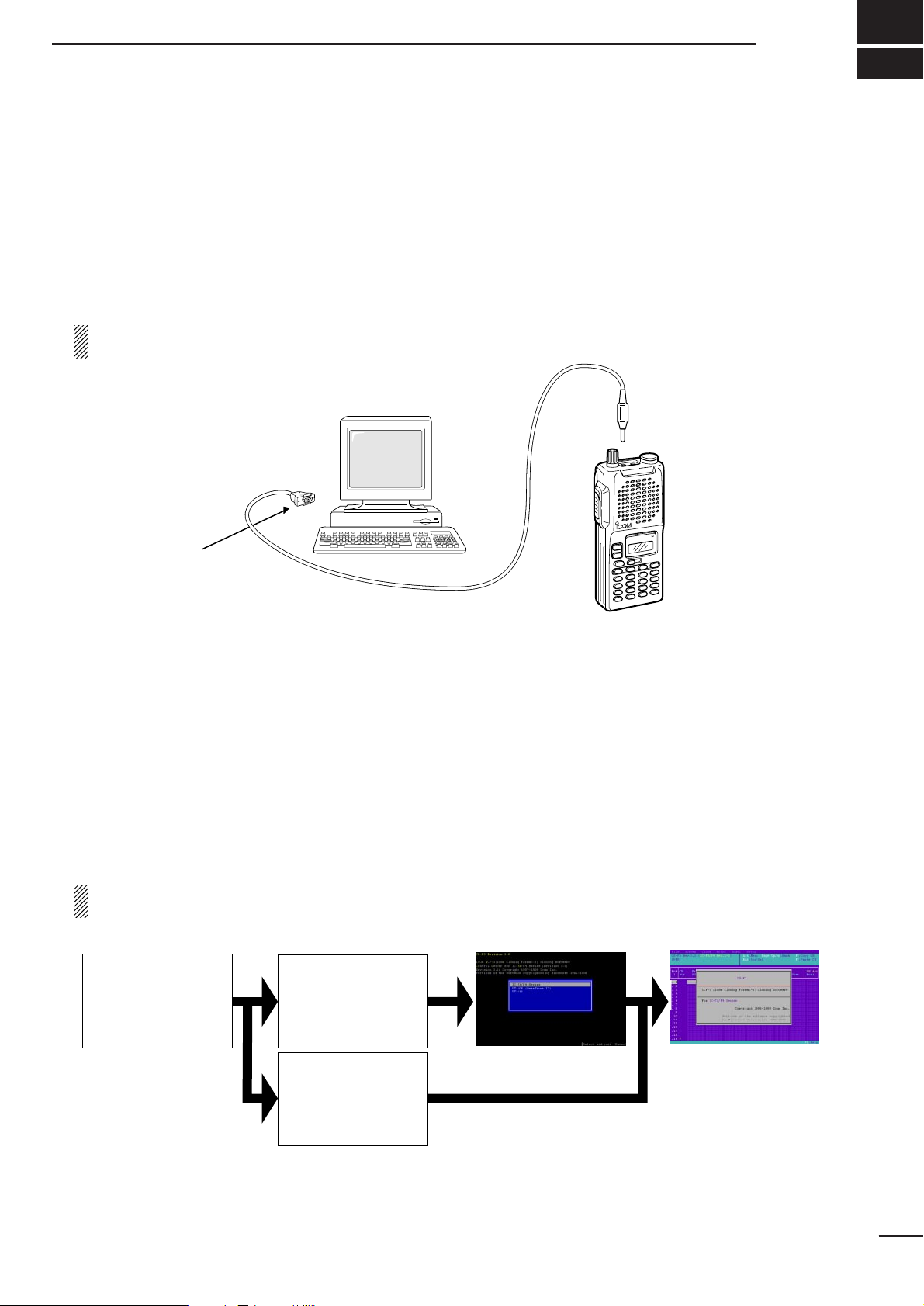
■ CONNECTION
Connect each item as in the following diagram.
CAUTION: Do not connect an antenna to the transceiver during cloning operation. Received signals
may cause cloning errors.
■ STARTING THE PROGRAM
q Boot up DOS.
w Insert the CS-F3 backup disk into drive A*.
e Type the following to start the program
iccf3.exe [Enter], or csf3.exe [Enter]
When csf3.exe is typed to start the program, skip step r.
r Select “IC-F3/F4 series” with the arrow keys ([⇑] and [⇓]), then push [Enter] key to start the program.
t After the start up screen appears, set or modify the data as desired.
• By pushing [Alt] or [Esc] key, the TOP menu will be brought up.
• Use the arrow keys ([⇑], [⇓], [⇐] and [⇒]) to select menu then push [Ent] or push
highlighted character
keys
to open the desired menu.
• The [Space] key or
Digit keys
toggle the setting.
y Use the “File” menu to save the data and to exit the program.
All cloning operations are performed from the computer’s keyboard (not from a mouse)—the only operation required on the transceiver side is power on.
*According to the PC’s condition.
PREPARATION
1
1
to the speaker
connector
to an RS-232C port
DB9 female plug
(incl. level converter circuit)
Personal
computer
OPC-478
A:\> A:\>iccf3.exe
Boot up DOS.
A:\>csf3.exe
Start up command.
Program start up screen
appears, followed by the
Memory Channel screen.
Select “IC-F3/F4 series”
then push [Enter] key.
Portion of this software are copyrighted by Microsoft Corporation. MS-DOS is a trademark of Microsoft Corporation. IBM PC/AT,
PS/2, PC-DOS and IBM DOS are trademarks of International Business Machines.
Page 4
2
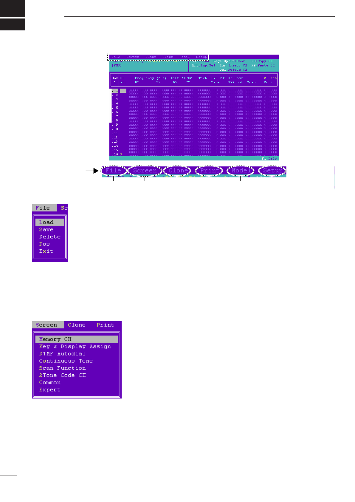
SCREEN DESCRIPTION
2
q File menu
q Load (p. 4)
Loads saved programming data from the specified disk/folder (directly). File
table capability is available.
w Save (p. 4)
Saves programming data to a desired disk/file. File extension, [.ICF], is added
automatically. File table capability is available.
e Delete (p. 4)
Deletes a specified file. File table capability is available.
r Dos
Allows you to use a DOS command. To return to the previous screen, type
“EXIT” then press [Enter].
t Exit
Quits and exits the program, then returns to the DOS prompt.
w Screen menu
For LMR—
appears only when LMR is selected in the Model menu. (p. 3)
y Memory CH (pgs. 5–8)
Sets operating frequencies and details.
u Key & Display Assign (pgs. 9–12)
Sets programmable key assign and display conditions, etc.
i DTMF Autodial (p. 13)
Sets automatic DTMF transmission condition,etc., up to 5 DTMF codes can
be programmed.
o Continuous Tone (p. 13)
Sets preset CTCSS frequencies or DTCS codes, up to 9 pairs (RX and TX)
frequencies or codes can be programmed.
!0 Scan Function (p. 14)
Sets scanning mode, conditions, etc.
!1 2Tone Code CH (pgs. 15–16)
Sets 2-tone operating conditions.
!2 Common (pgs. 17–19)
Sets commonly used timers, user password, etc.
!3 Expert (p. 20)
Sets extra customizable timers and features.
q w e r t y
Page 5
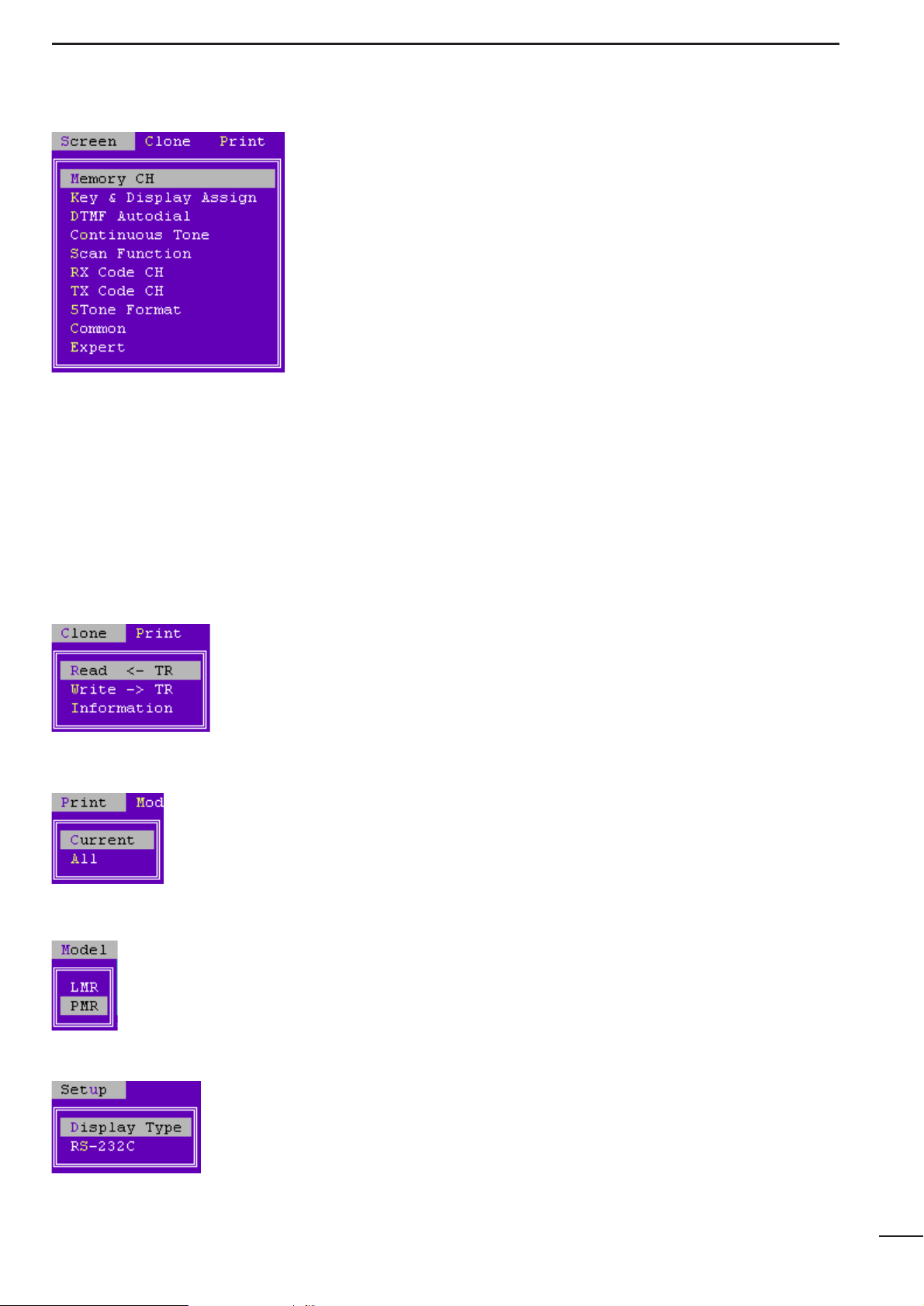
For PMR—
appears only when PMR is selected in the Model menu as follow.
!4 Memory CH (pgs. 21–27)
Sets operating frequencies and details.
!5 Key & Display Assign (pgs. 28–31)
Sets programmable key assign and display conditions, etc.
!6 DTMF Autodial (p. 32)
Sets automatic DTMF transmission condition,etc., up to 5 DTMF codes can
be programmed.
!7 Continuous Tone (p. 32)
Sets preset CTCSS frequencies or DTCS codes, up to 9 pairs (RX and TX) frequencies or codes can be programmed.
!8 Scan Function (p. 33)
Sets scanning mode, conditions, etc.
!9 RX Code CH (pgs. 34–36)
Sets receive 5-tone code, action, etc.
@0 TX Code CH (pgs. 37–38)
Sets transmit 5-tone code, conditions, etc
@1 5Tone Format (p. 39)
Specifies using 5-tone system.
@2 Common (pgs. 40–42)
Sets commonly used timers, user password, etc.
@3 Expert (pgs. 43)
Sets extra customizable timers and features.
e Clone menu
@4 Read <– TR (p. 44)
Reads the programmed data from the connected transceiver.
@5 Write –> TR (p. 44)
Programs setup data to the connected transceiver.
@6 Information (p. 44)
Shows detailed information of the connected transceiver.
r Print menu
@7 Current
Prints out currently displayed screen data.
@8 All
Prints out all set data.
t Model menu
@9 LMR
Only the LMR functions (2-tone) can be selected.
#0 PMR
Only the PMR functions (5-tone) can be selected.
y Setup menu
#1 Display Type (p. 45)
Selects the display type from color, monochrome 1 and 2.
#2 RS-232C (p. 45)
Selects one of the computer‘s RS-232C ports for cloning connection.
3
SCREEN DESCRIPTIONS
2
Page 6
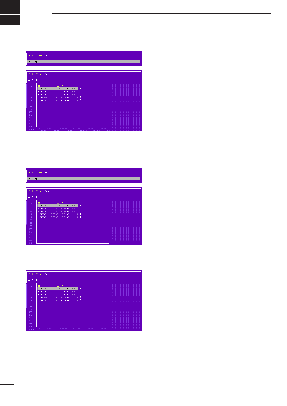
3-1 LOAD
Enter the file name then push [Ent] when exact file
name is known to load stored programming data.
When exact file name is unknown, enter wildcard (*)
then push [Ent] to display the file table. Select a file
with [⇑]/[⇓] key from the file table then push [Ent] to
load stored programming data.
The clone comment programmed in Clone Comment
in
4-7/5-9 Common
(p. 17: LMR/p. 40: PMR) is shown in
the file table for simple file selection and management
by the using file name as well as a clone comment
combination.
Go to Clone Comment— LMR
Go to Clone Comment— PMR
3-2 SAVE
Enter the file name then push [Ent], when saving the
programming data with a specified file name.
Enter wildcard (*) then push [Ent] to display the file
table, when confirming all available file names.
3-3 DELETE
Select the file with [⇑]/[⇓] key from the file table then
push [Ent], when unnecessary files exist.
4
FILE MENU OPERATION
3
Page 7
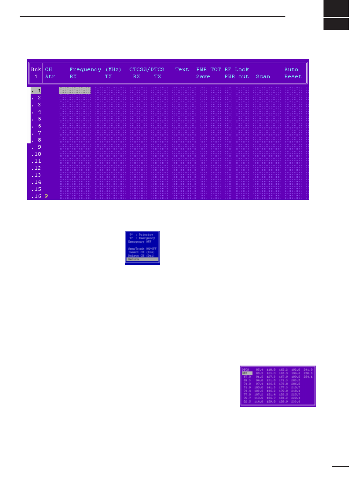
4-1 MEMORY CH
• CH Atr
Selects the channel attribution from P (Priority), E
(Emergency), and Emergency OFF.
Set the cursor to the CH Atr column,
then push [Return] key to display the
window as at right. Select the channel
attribution by pushing [⇑]/[⇓] keys.
P: Priority— “P” tagged channel becomes a priority
channel, simply recalled by pushing [Priority CH]
switch and also is automatically monitored during
the priority scan. Only 1 channel can be set.
E: Emergency— “E” tagged channel becomes an
emergency channel, immediately recalled and
sends emergency signal by pushing [Emergency
Single] or [Emergency Repeat] switch. Only 1
channel can be set.
Emergency OFF— Regular channel.
SmarTrunk ON/OFF switches SmarTrunk II capabilities. In this case, an optional UT-105 SmarTrunk II Logic
Board
and extra programming with an EX-2095 appli-
cation in the CS-F3 are required.
See pages 46–48,
8 PROGRAMMING for SmarTrunk II
OPERATION
, for details.
[Priority CH], [Emergency Single] and [Emergency
Repeat] switches are assigned in
4-2 KEY & DISPLAY
ASSIGN
(pgs. 9, 11).
Go to 8 PROGRAMMING for SmarTrunk II OPERATION
Go to 4-2 KEY & DISPLAY ASSIGN
• Frequency— RX and TX
Enter receive and transmit frequencies within the following frequency range in either 5, 6.25 or 7.5 kHz
steps* for the RX and TX columns, respectively.
IC-F3/S: 136–150, 146–174 MHz
IC-F4/S: 400–430, 440–470, 470–500, 490–512 MHz
*according to version
Transmit inhibit can be selected by pushing [Space]
key.
When no receive frequency is entered, other data cannot be programmed in the channel.
When SmarTrunk ON/OFF is selected in CH Atr as at
left, operating frequencies must be programmed from
channel 1 without a blank.
• CTCSS/DTCS— RX and TX
Enter full CTCSS frequency (incl. decimal point; otherwise
a DTCS code is entered)
or a 3-digit DTCS code as well
as polarity for receive and transmit in the RX and TX
columns, respectively.
By pushing the [Enter] key, the CTCSS frequency list
as at right appears for
simple frequency
selection. Also selectable with [Space] or
[Back Space] keys
without list indication.
The polarity of DTCS is selectable by pushing the
[Space] or [Back Space] key from N (Normal) and I
(Inverse).
5
SCREEN MENU OPERATION— LMR
4
Page 8

4-1 MEMORY CH— continued
• Text
Enter up to a 7-character text in the Text column for
memory name, channel usage, etc.
The usable characters are A–Z, 0–9, $, ’, (, ), –, /, <, =,
>, @, [, \, ], _, | and ~.
When no text is entered, the channel number is indicated.
• PWR Save
Selects power save capability from ON and OFF.
The power save start timings are programmed in the
PWR Save Start Timer (1st)/(2nd) in
4-8 EXPERT
(p. 20).
When SmarTrunk ON/OFF is selected in CH Atr in this
screen (p. 5), “OFF” must be selected.
Go to PWR Save Start Timer (1)/(2)
Go to CH Atr
•TOT
Selects time-out-timer function capability from ON and
OFF.
Continuously transmittable time is limited by the timer
when ON is selected. However, time-out timer must be
set to ON due to local regulation, in some countries.
The time period is programmed in the TOT— Timer in
4-7 COMMON
(p. 17).
When SmarTrunk ON/OFF is selected in CH Atr in this
screen (p. 5), “OFF” must be selected.
Go to TOT— Timer
Go to CH Atr
• RF PWR
Selects transmit output power from H (High) and L
(Low).
The selected output power setting for each channel
can be switched to either temporary or permanent,
according to the setting in RF PWR (H/L) in
4-2 KEY &
DISPLA YASSIGN
(p. 11) via [High/Low] switch.
The [High/Low] switch is assigned in the
4-2 KEY &
DISPLAY ASSIGN
(p. 10)
Go to RF PWR (H/L)
Go to 4-2 KEY & DISPLAY ASSIGN
• Lock out
Selects transmission lock out (temporary inhibit) capability from Busy, Rpt (Repeater) and OFF.
Busy : [PTT] switch cannot be activated while the
operating channel/repeater is in use.
Rpt : [PTT] switch can be activated while receiving
a signal with matched CTCSS (or DTCS)
tone or no signals.
OFF : No restriction for receiving a signal.
In addition, [PTT] switch is not activated for an extra
time period in the case of when the lockout penalty
timer, programmed in the Lockout Penalty T imer in
4-
7 COMMON
(p. 18), is activated even if the transceiver
in a transmittable condition.
Go to Lockout Penalty Timer
6
SCREEN MENU OPERATION— LMR
4
Page 9
7
4-1 MEMORY CH— continued
• Scan
Selects scanning condition with permission of scanning list modification from “Blank” (Inh), “Blank” (Ena),
Tag (Inh) and Tag (Ena).
The Tag (Inh) or Tag (Ena) selected channels are
scanned.
“Blank” (Ena) or Tag (Ena) selected channels can be
added or deleted to/from scan list by pushing and holding [Scan] switch
.
When SmarTrunk ON/OFF is selected in CH Atr in this
screen (p. 5), “Blank” (Inh) must be selected.
[Scan] switch is assigned in the
4-2 KEY & DISPLAY
ASSIGN
(p. 9)
Go to CH Atr
Go to 4-2 KEY & DISPLAY ASSIGN
• Auto Reset
Selects reset timer from Tim-Aand Tim-B to restarting
scanning when the power ON scan function is turned
ON.
Tim-A, Tim-B:
Restarts scanning after specified time (Timer A
or Timer B)
has passed from a disappearing sig-
nal or key operation is finished.
The time period of Timer A and Timer B are programmed in the Auto Reset— Timer A, Timer B in
4-
7 COMMON
(p. 17), respectively.
To turn OFF the function, select the timer which OFF
(0 sec.) is programmed.
The power ON scan function is specified in PWR ON
Scan in
4-5 SCAN FUNCTION
(p. 14)
Go to Auto Reset— Timer A, Timer B
Go to PWR ON Scan
• 2Tone Dec
Selects transceiver’s action when a matched 2-tone
code is received from 1, 2, 3 and OFF.
1, 2, 3: Activates a specified channel 1, 2 or 3 as pro-
grammed in the
4-6 2TONE CODE CH
(pgs. 15, 16).
OFF : Nothing changes.
Go to 4-6 2TONE CODE CH
• Log IN/OFF
Selects automatic ID transmission condition in relation
with [PTT] from L-IN, L-OFF, Both and OFF.
L-IN : ID is transmitted each time [PTT] is pushed.
L-OFF: ID is transmitted each time [PTT] is released.
Both : ID is transmitted each time [PTT] is pushed
and released.
OFF : No ID is transmitted with [PTT].
Log/ID code is used as the ID code, programmed in
4-
3 DTMF AUTODIAL
(p. 13).
When SmarTrunk ON/OFF is selected in CH Atr in this
screen (p. 5), “OFF” must be selected.
Go to 4-3 DTMF AUTODIAL
Go to CH Atr
SCREEN MENU OPERATION— LMR
4
Page 10

8
SCREEN MENU OPERATION—LMR
4
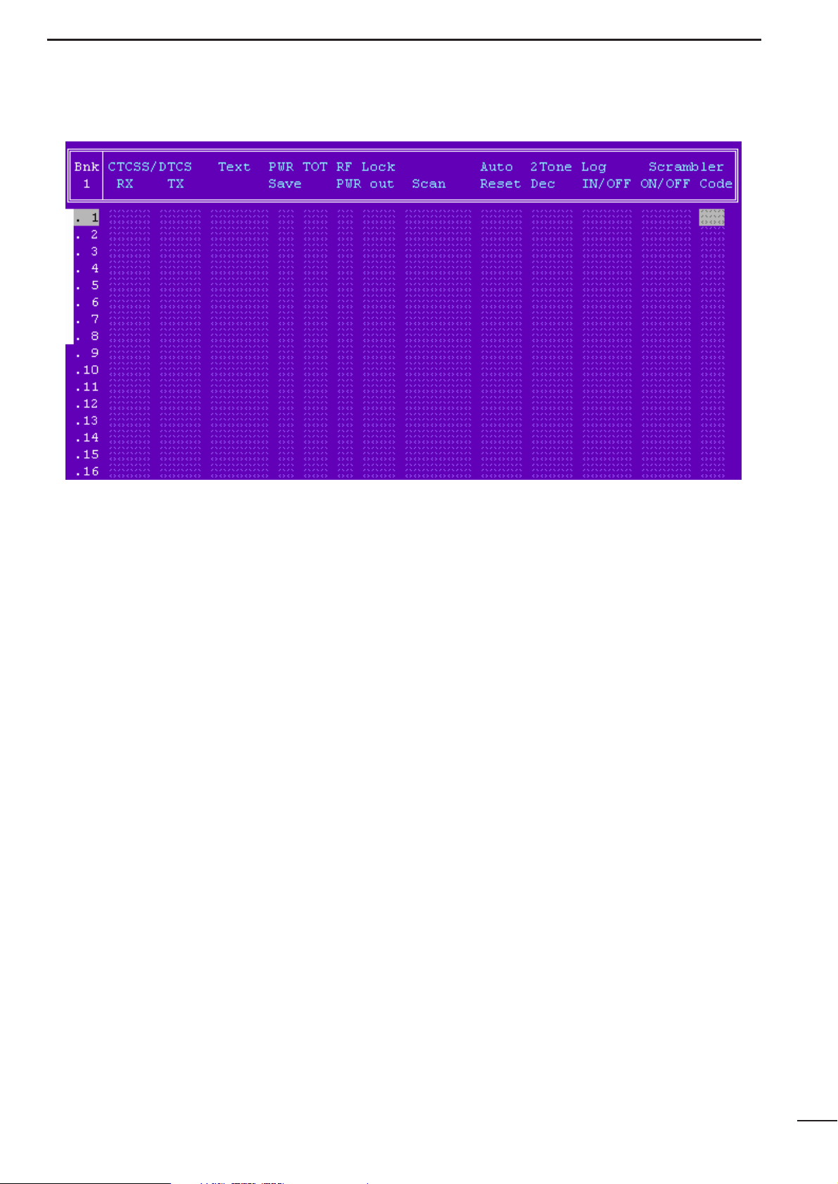
4-1 MEMORY CH— continued
• Scrambler— ON/OFF/INH
Selects voice scrambling function initial setting from
ON, OFF and INH.
When ON or OFF is selected, the voice scrambling
function can be manually switched with the [Scrambler]
switch, however, the function cannot be manually
switched ON when INH is selected.
An optional UT-109 or UT-110 VOICE SCRAMBLER UNIT is
required.
The [Scrambler] switch is assigned in Key assign in
4-
2 KEY & DISPLAY ASSIGN
(p. 11).
Go to 4-2 KEY & DISPLAY ASSIGN
• Scrambler— Code
Enter voice scrambling code within 1–32 using UT-109
or UT-110 with ‘Non-rolling’ selection or within 1–255
using UT-110 with ‘Rolling’ selection installed.
In addition, the Scrambler Group Code in
4-7 COM-
MON
(p. 19) must be programmed when UT-110 is
installed and ‘Rolling’ is selected in Scrambler Type in
4-7 COMMON
(p. 19).
Go to Scrambler Group Code
Go to Scrambler Type
Page 11
9
SCREEN MENU OPERATION— LMR
4
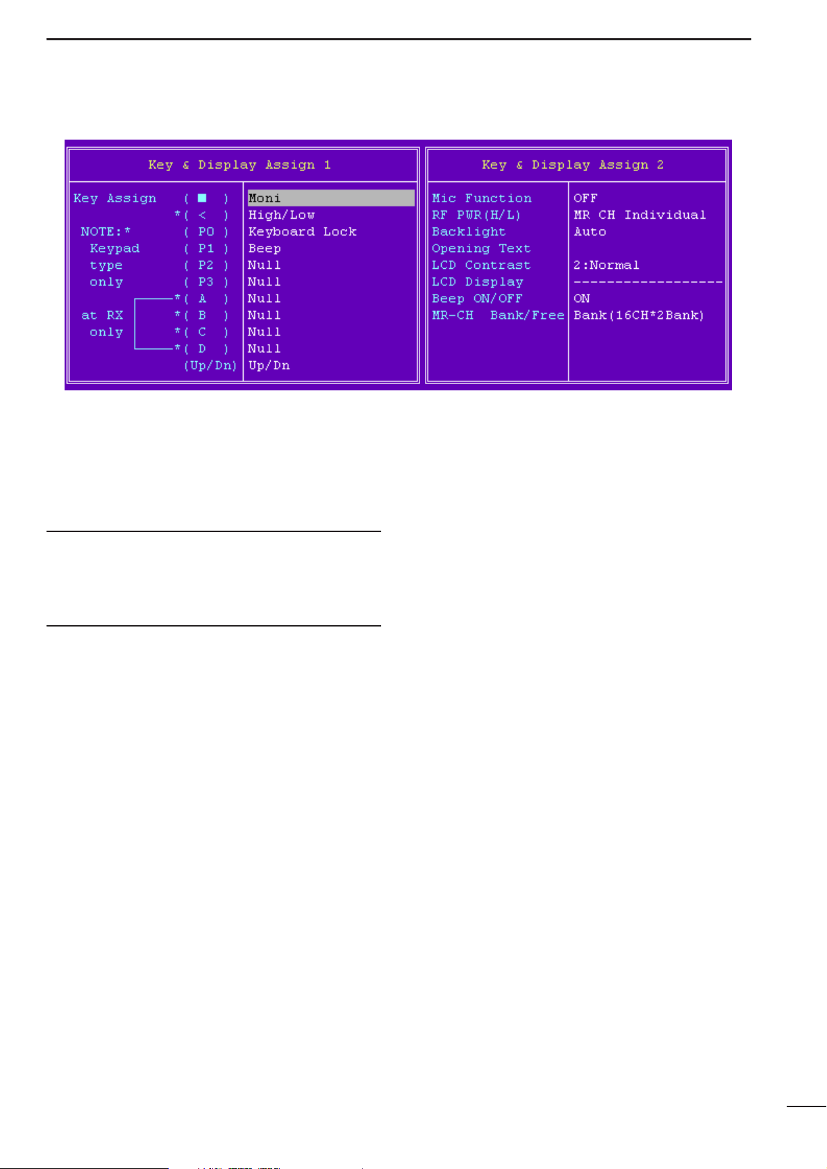
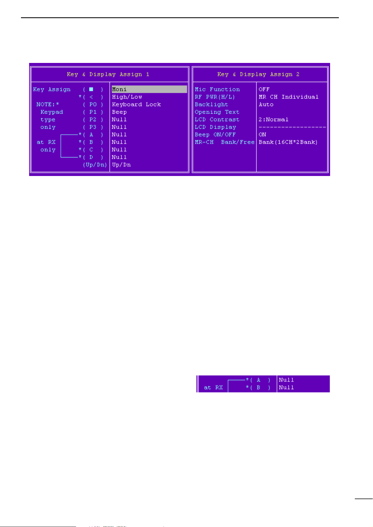
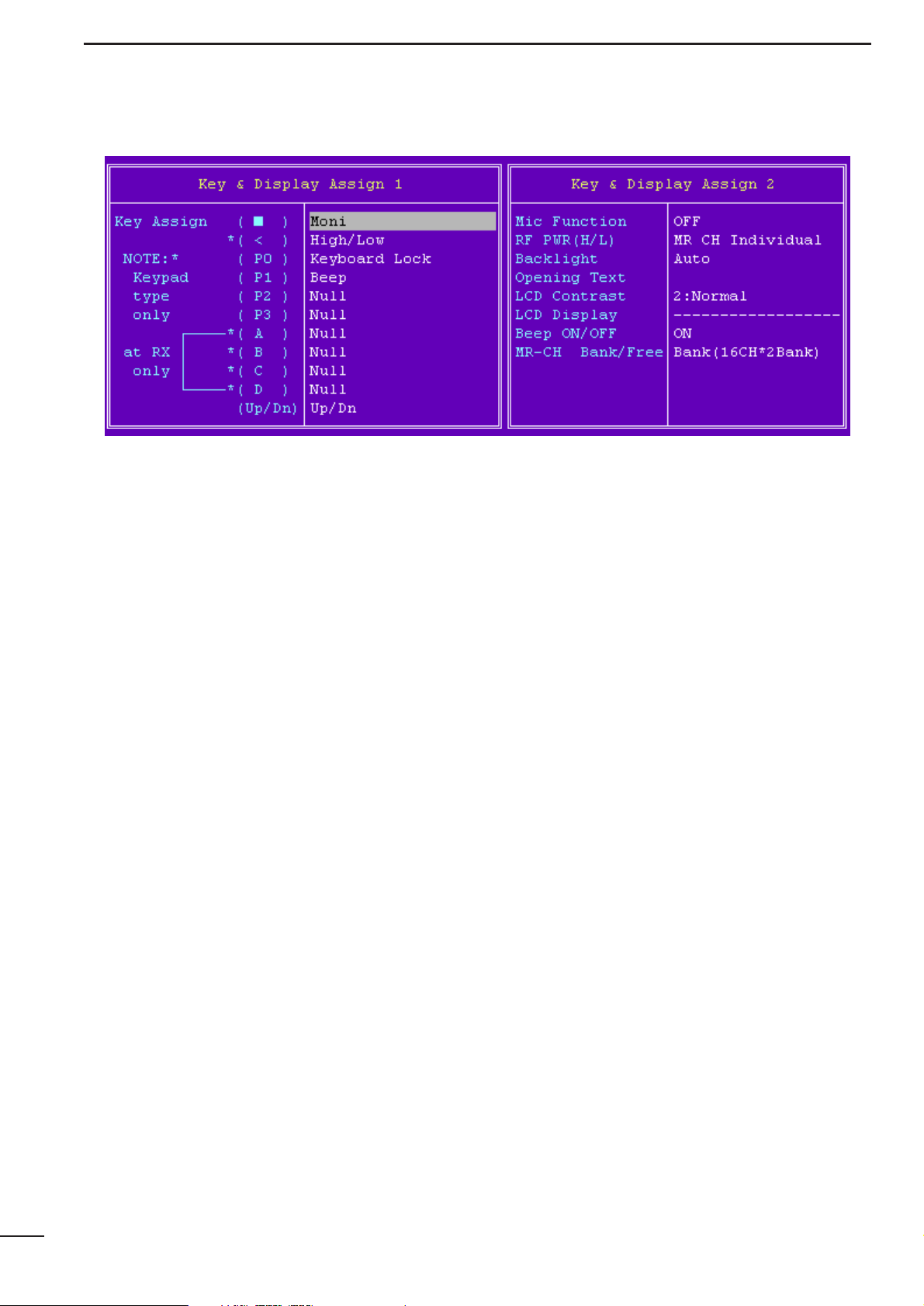
4-2 KEY & DISPLAY ASSIGN
• Key assign—(■), *(<), (P0), (P1), (P2), (P3), *(A),
*(B), *(C), *(D), (Up/Dn)
Assign a function for each programmable switch.
Assignable functions and actions are as follows.
Assigned functions to (A), (B), (C) and (D) switches activate
in receive mode only.
*Not available for the IC-F3S and IC-F4S.
IMPORTANT for SmarTrunk IITMOPERATION!
DO NOT assign the specified functions to the *(A),
*(B), *(C) and *(D) switches when programming for
SmarTrunk IITMoperation, due to fact that the Speed
Dial function is assigned for these switches.
Null : No function is assigned. However, lights
LCD backlight for 5 sec. when ‘Auto’ is
selected in Backlight (p. 12) in this screen.
Go to Backlight
Light : switches LCD backlight ON and OFF.
Bank Up :
Changes memory channel bank for when
either Bank (8CH*4Bank), Bank (16CH*2Bank)
or Bank (20CH+12CH) is selected in the MR-
CH Bank/Free (p. 12) in this screen.
Go to MR-CH Bank/Free
Scan A, Scan B:
When the power ON scan function is turned OFF;
Push to start and cancel scanning operation. In case of transmission during scan,
cancels scanning when in Scan A, and
pauses scanning, then resumes scanning
after passing the time period specified in
Auto Reset in
4-1 MEMORY CH
(p. 7) when
Scan B is selected.
The scanning channel can be added or
deleted to/from the scanning channel list by
pushing and holding the switch only for Tag
(Ena) or “blank” (Ena) in selected channels,
programmed in Scan in
4-1 MEMORY CH
,
(p. 7).
When the power ON scan function is turned ON;
Push to pause scanning when in Scan A,
and push to cancel scanning when Scan B
is selected. In case of transmission during
scan, pauses scanning, then resumes
scanning after passing the time period
specified in the Auto Reset in
4-1 MEMO-
RY CH
(p. 7) when in Scan A. Cancels scan-
ning when Scan B is selected.
While pausing scan when in Scan A, or after
cancelling scan when Scan B is selected,
the scanning channel can be added or
deleted to/from the scanning channel list by
pushing and holding the switch only for Tag
(Ena) or “blank” (Ena) in selected channels,
programmed in Scan in
4-1 MEMORY CH
,
(p. 7).
The power ON scan function is specified in PWR ON
Scan in
4-5 SCAN FUNCTION
(p. 14).
NOTE: Scan A and Scan B cannot be assigned at
the same time, because the transceiver cannot have two different scans.
Go to Auto Reset
Go to Scan
Go to PWR ON Scan
Priority CH (Rewrite):
Selects the priority channel programmed in
CH Atr in
4-1 MEMORY CH
(p. 5). Also re-
assigns priority channel by pushing and
holding the switch.
Go to CH Atr
Moni : Push to mutes the CTCSS, DTCS or 2-tone
squelch, push for 1 sec. to releases the
CTCSS, DTCS or 2-tone squelch mute.
Open any squelches/deactivate any mutes
while pushing this switch.
Page 12

10
4-2 KEY & DISPLAY ASSIGN— continued
High/Low: Switches transmit output power level from
the independent settings of each channel.
The switched output power can be used for
initial setting, when “Override” is selected in
the RF PWR (H/L) in this screen (p. 11).
Go to RF PWR (H/L)
C. Tone CH Ent:
Selects continuous tone channel via [▲] or
[▼] switch after pushing the switch for temporary operation. Also changes continuous
tone frequency/code setting, programmed
in the CTCSS/DTCS— RX and TX in
4-1
MEMORY CH
(p. 5), via [▲] or [▼] switches
while pushing and holding this switch.
The continuous tone channel is programmed in
4-4 CONTINUOUS TONE
(p. 13),
Go to CTCSS/DTCS— RX and TX
Go to 4-4 CONTINUOUS TONE
Talk Around:
Switches the talk around function ON and
OFF.
This function makes temporal simplex operation on the duplex/repeater channel.
DTMF Autodial:
For entering the DTMF autodial mode and
then transmits the stored DTMF code after
a selection via [▲] or [▼] switch for each
operation.
For entering the DTMF code re-programming mode by pushing and holding and
then completes the setting by pushing (IC-
F3/F4)
or pushing and holding the (IC-
F3S/F4S)
switch after DTMF code has been
entered as follows.
To enter DTMF code—
IC-F3/F4; Directly enter desired DTMF code by
using [0]–[9], [A]–[D], [✽ ] and [#] switches.
IC-F3S/F4S; Select the code number via [▲] or [▼]
switches then push this switch to set
the next code number.
This function cannot be assigned to [A]–[D]
switches on the transceiver.
The DTMF code for auto dialling is programmed in
4-3 DTMF AUTODIAL
(p. 13).
Go to 4-3 DTMF Autodial
Re-Dial : Transmits the last-transmitted DTMF code
again. Acts for both manual DTMF and
autodial.
Re-Dial will be cleared when the transceiver is turned OFF.
SCREEN MENU OPERATION—LMR
4
Page 13
11
4-2 KEY & DISPLAY ASSIGN— continued
Emergency Repeat, Emergency Single:
Immediately selects emergency channel
and automatically sends a repeated emergency signal at specified time intervals or
an emergency signal once, by pushing and
holding the switch.
This function cannot be assigned to [A]–[D]
switches.
The emergency channel is specified in CH
Atr in
4-1 MEMORY CH
(p. 5) and the time
intervals are specified in the Emer
Start/Repeat in
4-8 EXPERT
(p. 20).
Go to CH Atr
Go to Emer Start/Repeat
Keyboard Lock:
Switches keyboard lock function ON and
OFF.
Beep : Switches key touch beep ON and OFF.
Shift : Shifts the CPU’s clock frequency by push-
ing and holding the switch.
Scrambler:
Switches voice scrambler function ON and
OFF when an optional voice scrambler unit,
UT-109 or UT-110, is installed.
OPT1 Out:
Switches an optional output port High and
Low.
OPT1 Momentary Out:
Outputs a High or Low pulse from an
optional output port.
Trunking Group SW:
Selects trunking group.
This function is used for the SmarTrunk II
TM
operation only.
Turbo SpeeDial A, B, C, D:
Immediately calls commonly used telephone or subscriber numbers during
SmarTrunk operation. See page 44 for
details
This function is used for the SmarTrunk II
TM
operation only.
• Mic Function
Selects remote control capability from an optional HM75A SPEAKER MICROPHONE.
[▲], [▼], [A] and [B] switches on the HM-75A operate
as [▲], [▼], [A] and [B] switches on the transceiver,
respectively.
When using with IC-F3S or IC-F4S, [A] and [B] switches on the HM-75A operate with the function assigned
in the *( A) and * ( B ) in this screen, respectively.
• RF PWR (H/L)
Selects transmit output power setting condition from
MR CH Individual and Override.
The selected transmit output power level via
[High/Low] switch is kept for all channels regardless of
the individual power setting programmed in RF PWR in
4-1 MEMORY CH
(p. 6) when ‘Override’ is selected.
However, the selected transmit output power level via
[High/Low] switch is output temporarily when “MR CH
Individual” is selected.
Go to RF PWR
SCREEN MENU OPERATION— LMR
4
Programming memory Speed Dial
q Push and hold the [✽ ] until a high-pitch beep is heard.
w Enter the memory location (0–9, A, B, C, D), the telephone or
subscriber number, then [1], [✽] (or [3], [✽] if for another system subscriber).
• A high-pitch beep informs successful programming.
• Memories [A]–[D] are used for the Turbo SpeeDial.
Note: This function is available for the IC-F3/F4 only.
Page 14
12
4-2 KEY & DISPLAY ASSIGN— continued
• Backlight
Selects LCD backlight lighting condition from Auto,
Continuous and OFF.
Auto : Lights for 5 sec. when any switch except
[PTT] is pushed.
Continuous:
Lights continuously while the transceiver is
powered ON.
OFF : Does not light with any operation.
• Opening Text
Enter up to a 7-character transceiver opening message.
The usable characters are A–Z (uppercase), 0–9, $, ‘,
(, ), –, /, <, =, >, @, [, \, ], _, |, ~.
• LCD Contrast
Selects LCD contrast level from 1: Low and 2: Normal.
• Beep ON/OFF
Selects key-touch beep output capability. (Not for lock-
out timer, TOT, etc.)
• MR-CH Bank/Free
Selects memory channel combination from Bank
(8CH*4Bank), Bank (16CH*2Bank), Bank (20CH+12CH)
and Free.
Bank (8CH*4Bank), Bank (16CH*2Bank) or Bank
(20CH+12CH) divides all available 32 channels into 4,
2 channels groups or 20 channels plus 12 channels,
respectively.
Free— channels can be used continuously.
SCREEN MENU OPERATION— LMR
4
Page 15
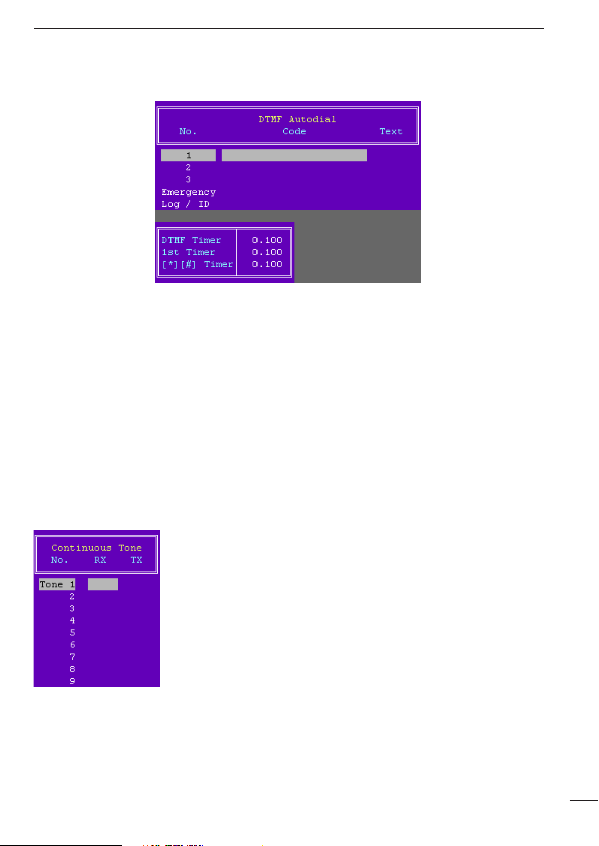
4-4 CONTINUOUS TONE
• RX and TX
Enter full CTCSS frequency for each RX and TX as
instructed in the CTCSS/DTCS— RX and TX in
4-1
MEMORY CH
(p. 5).
Go to CTCSS/DTCS— RX and TX
The programmed continuous tone combinations can
be used for temporary or permanent encoder and/or
decoder operation.
Temporary operation;
Push [C. Tone CH Ent] switch, then select a continuous tone memory channel via [▲] or [▼] switch.
Permanent operation;
Select a continuous tone memory channel via [▲] or
[▼] switch, while pushing and holding [C. Tone CH
Ent] switch.
The [C. Tone CH Ent] switch is assigned in
4-2 KEY &
DISPLAY ASSIGN
(p. 10).
Go to 4-2 KEY & DISPLAY ASSIGN
13
4-3 DTMF AUTODIAL
• Code
Enter up to a 24-digit DTMF code for simple and quick
DTMF code transmission.
The usable characters are 0–9, A–F (#/✽ used as F/E).
• Text
Enter up to a 7-character text for easy recognition of
DTMF code usage, etc.
When no text is programmed, the programmed DTMF
code is scrolled.
The usable characters are A–Z (uppercase), 0–9, $, ‘, (,
), –, /, <, =, >, @, [, \, ], _, |, ~.
• DTMF Timer
Enter time period/signal length for each DTMF code
emission and interval.
• 1st Timer
Enter time period/signal length for 1st DTMF code
emission and interval corresponding to the scanning or
power saving of the transceiver.
•[✽] [#] Timer
Enter time period/signal length for [✽] and [#] DTMF
code signal emission and interval.
These codes may be used for control codes depending
on signaling system.
When these special codes are used for the 1st digit
code, the 1st Timer as above has priority over this setting.
Page 16

14
SCREEN MENU OPERATION— LMR
4
4-5 SCAN FUNCTION
• Mode
Selects scanning mode from the Mode 1, 2, 3 and OFF.
Mode 1 : Normal scan. Scans all ‘Tag (Inh)’ or ‘Tag
(Ena)’ selected channels. The scan proceeds in sequence from lower to higher
channel number.
Mode 2 : Priority scan. The priority channel is moni-
tored every fixed time period during scan
(depending on version), or every specified
time period programmed in the Stop Timer
in this screen, as at right, during pause. The
busy or paused channel is retained when
scan is cancelled.
Mode 3 : Priority scan. Same scanning sequence as
Mode 2 above. The priority channel is
retained when scan is cancelled.
OFF : Scan function cannot be controlled from the
transceiver keypad.
The scanning channels, ‘Tag (Inh)’ or Tag ‘(Ena)’, are
selected in Scan in
4-1 MEMORY CH
(p. 7).
The priority channel is selected in CH Atr in
4-1 MEM-
ORY CH
(p. 5).
Go to Scan
Go to CH Atr
• Text
Enters up to a 7-character text to indicate messages,
etc. during scanning.
When no text is programmed, scanning channel text or
number is scrolled.
The usable characters are A–Z (uppercase), 0–9, $, ‘, (,
), –, /, <, =, >, @, [, \, ], _, |, ~.
• PWR Save
Selects power save capability during scanning.
Total scanning speed is decreased when the function
is turned ON.
• Stop Timer
Enters time period for scan pausing on a busy channel
(watching interval) when receiving a signal in scan mode
2 or 3 (priority scan), specified in Mode as at above left.
• Resume Timer
Enters time period for resuming scanning after signal
disappears.
• PWR ON Scan
Selects automatic scan start capability at power ON
from ON and OFF.
Also, automatically restarts scanning even once scanning is cancelled for call transmission or reception,
etc., after a specified time has passed when the signal
disappears or key operation is finished when ON is
selected.
When SmarTrunk ON/OFF is selected in CH Atr in this
screen (p. 5), “OFF” must be selected.
The scanning restart condition is selected in Auto
Reset in
4-1 MEMORY CH
(p. 7), and the time period
is programmed in the Auto Reset— Timer A, Timer B
in
4-7 COMMON
(p. 17).
Go to CH Atr
Go to Auto Reset
Go to Auto Reset— Timer A, Timer B
Page 17
15
SCREEN MENU OPERATION— LMR
4
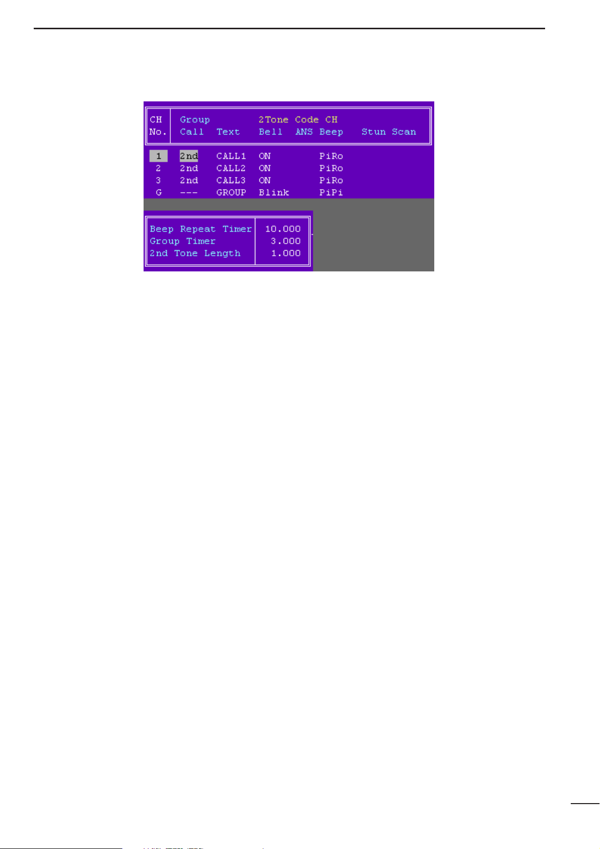
4-6 2TONE CODE CH
• Group Call
Selects which tone digit,1st or 2nd, is used for the
group code.
• Text
Enter up to a 7-character text into the column directly.
The programmed text appears when a matched 2-tone
code signal is received.
The usable characters are A–Z (uppercase), 0–9, $, ‘, (,
), –, /, <, =, >, @, [, \, ], _, |, ~.
• Bell
Selects the bell indicator condition when receiving a
matched 2-tone from ON, Blink, Null, and OFF.
ON : The bell indicator appears until operation of
key.
Blink : The bell indicator blinks until operation of
key.
Null : The bell indicator condition is not changed
even when a matched code is received.
OFF : The bell indicator goes off.
• ANS
Turns the answer back function ON and OFF.
The function transmits a 1 kHz single tone for 2 sec.
when receiving a matched 2-tone.
• Beep
Selects beep type when matched 2-tone code is
received from Pi, PiPi, PiRo, Pi/R, PiPi/R, PiRo/R, Null
and OFF.
Null : Beep emission (or non emission) is retained
even when matched 2-tone is received.
OFF : Repeated beep emission is turned OFF.
Pi : 1 high beep once.
PiPi : 2 high beeps once.
PiRo : 1 high and 1 low beep 3 times.
Pi/R : 1 high beep repeated at the specified time
period.
PiPi/R : 2 high beeps repeated at the specified time
period.
PiRo/R : 1 high, 1 low beep 3 times, repeated at the
specified time period.
The repeating time period is programmed in the Beep
Repeat Timer (p. 16) in this screen.
Go to Beep Repeat Timer
• Stun
Selects transceiver’s basic condition when matched 2tone code is received from Kill, Stun and OFF.
Kill : The transceiver cannot be used. Cloning is
necessary to activate the transceiver.
Stun : A message, “SORRY”, appears and trans-
ceiver cannot be used. To use the transceiv-
er, turn power OFF and ON again. At this
time, password input is necessary if the
power ON password is programmed in User
Password in
4-7 COMMON
(p. 17).
OFF : The transceiver can be used continuously.
Go to User Password
Page 18

4-6 2TONE CODE CH— continued
• Scan
Selects scanning condition when a matched 2-tone
code is received from Cancel, Start and Null.
Cancel: Cancels the scan.
Start : Starts the scan.
Null : Scan condition is unaffected.
The cancelled or started scan type and conditions are
specified in
4-5 SCAN FUNCTIONS
(p.14), and the
scanning can be restarted or cancelled via [Scan]
switch, assigned in
4-2 KEY & DISPLAYASSIGN
(p. 9).
Go to 4-5 SCAN FUNCTIONS
Go to 4-2 KEY & DISPLAY ASSIGN
• Beep Repeat Timer
Enters beep emission repeating time period.
When “Pi/R”, “PiPi/R” or “PiRo/R” is selected in Beep
in this screen (p. 15), beeps are repeated at this period.
Go to Beep
• Group Timer
Enter time period for group tone decoding.
The transceiver reads the tone as a group code in the
case that the received tone is longer than the programmed time period.
• 2nd Tone Length
Enter time period for 2nd digit tone decoding within
0–2.55 sec.
16
SCREEN MENU OPERATION— LMR
4
Page 19

SCREEN MENU OPERATION— LMR
4
17
4-7 COMMON
• User Password
Enters up to a 4-digit user password for the power ON
password function or for cancelling the “Stun” condition.
The power ON password function is specified in PWR
ON Password in this screen (p. 18), and the “Stun”
function is specified in Stun in
4-6 2TONE CODE CH
(p. 15).
Go to Power ON Password
Go to Stun
• Clone Comment
Enters up to a 16-character text for quick identification
of a transceiver’s content.
The programmed comment of connected transceiver
can be checked without reading all other existing programmed data. See page 44,
6-3 INFORMATION
, for
details.
The programmed comment of saved programming
data can also be checked in the file table.
See page 4,
3 FILE MENU OPERATION
for details.
Go to 6-3 INFORMATION
Go to 3 FILE MENU OPERATION
• Auto Reset— Timer A, Timer B
Enter time period for restarting the scan from a disappearing signal or when key operation is finished.
To turn OFF the Auto Reset function, enter “0 (zero)” to
one of these settings. (“OFF” will be indicated)
The programmed settings are selected in Auto Reset
in
4-1 MEMORY CH
(p. 7) and are related with the PWR
ON Scan in the
4-5 SCAN FUNCTION
(p. 14).
Go to Auto Reset
Go to PWR ON Scan
• TOT— Timer
Enters continuously transmittable time period (Time-out
timer)
. Maximum time period is specified for 30, 60 or
180 sec., etc. according to country, local regulation.
The time-out timer function can be turned ON or OFF
for each operating channel in TOT in
4-1 MEMORY CH
(p. 6).
DO NOT set to only a few seconds, as transmitting will
be impossible.
Go to TOT
• TOT— Penalty Timer
Enters un-transmittable time period for penalty when
continuously transmitted time has exceeded the specified time period programmed in TOT— Timer as
above.
The TOT penalty time is the transmit inhibit period
when the time-out timer is activated.
• TOT— ID Out (DTMF)
Selects automatic ID transmission capability from ON
and OFF.
The function automatically transmits an ID code when
the time-out timer activates and just before transmission is inhibited.
The ID code is programmed in
No. Log/ID
in
4-3 DTMF
AUTODIAL
(p.13).
Go to DTMF AUTODIAL
Page 20

4-7 COMMON— Continued
• TOT— Beep
Selects warning beep output capability for TOT function. Emits warning beep 10 sec. before compulsory
shut down of the transmission.
The transceiver emits warning beeps 10 sec. before ,
and the time-out timer activates when this setting is
turned ON.
• Lockout Penalty Timer
Enters un-transmittable time period for penalty when
transmitted on busy channel. The un-transmittable
condition is kept for the programmed time period even
if the channel is cleared.
The lockout penalty time is the transmit inhibit period
when the user attempts to transmit while in a lockout
condition. The transmission is inhibited for the lockout
penalty time even when the lockout condition is
cleared.
• CTCSS Reverse Burst
Enters time period for transmission delay with [PTT]
switch operation and CTCSS signal.
The transceiver still transmits for the programmed period without the CTCSS encoder after [PTT] is released.
This removes the transceiver’s ‘Squelch delay’.
• PWR ON Password
Selects power ON password function capability from
ON and OFF.
When the function is turned ON it is necessary to enter
the 4-digit password programmed in the User
Password (p. 17) in this screen. However, the pass-
word must be entered after receiving a “Stun” signal
regardless of this setting.
The Stun condition is programmed in Stun in
4-6
2TONE CODE CH
(p. 15).
Go to User Password
Go to Stun
• Transceiver Data Out
Selects transceiver’s programmed data out capability
by both using this software and cloning between transceivers from Enable and Disable.
The setting does not inhibit data writing, therefore over
writing data is still possible even when Disable is
selected.
18
SCREEN MENU OPERATION— LMR
4
• CTCSS Reverse Burst
Tone output
ON
OFF
RF power
output
ON
OFF
Time
PTT action
ON
OFF
CTCSS Reverse Burst
Page 21

19
SCREEN MENU OPERATION— LMR
4
4-7 COMMON— Continued
• Scrambler Type
Selects scrambler type from Rolling and Non-rolling.
Selects Rolling when the optional voice scrambler unit,
UT-110 (#01), is installed, selects Non-rolling when UT109 is installed.
UT-110 and UT-109 are not compatible due to different
scrambling systems. However, UT-110 can be used
instead of UT-109 by selecting Non-rolling type in this
item
The Scrambler Group Code as follows must be pro-
grammed when UT-110 is used with Rolling setting.
• Scrambler Group Code
Selects scrambler group code from 1, 2, 3 and 4 when
the optional voice scrambler unit, UT-110 (#01), is
installed and Rolling is selected in the Scrambler T ype
as above.
It is not required to program when the optional voice
scrambler unit, UT-109, is installed.
• Synchronous Capture
Selects synchronous capture mode from Standard and
Continuous.
It is recommended that Standard is selected for simplex/normal operation, Continuous for repeater operation.
• Tone Start Timing
Selects reference tone signal delay time from OFF,
0.3sec., 0.6 sec. and 1.1 sec.
The setting is used to synchronize voice scrambling
timing when the other stations/transceivers are in
power save mode.
Page 22

4-8 EXPERT
• Fast Scan Timer
Enters time period for scanning of each channel without CTCSS/DTCS programming.
An appropriate time is set by default and scan may not
stop when setting a value less than the default.
• Slow Scan Timer
Enters time period for scanning of each channel with
CTCSS/DTCS programming.
An appropriate time is set by default and scan may not
stop when setting a value less than the default.
• TX DTCS Inverse
Selects the transmit DTCS code polarity.
In order for the transceiver to communicate using a
DTCS code, the polarity of the transmitting transceiver’s transmit code must be the same as the polarity of
the receiving transceiver’s receive code.
• RX DTCS Inverse
Selects the receive DTCS code polarity.
In order for transceivers to communicate using DTCS
codes, the polarity of the receiving transceiver’s
receive code must be the same as the polarity of the
transmitting transceiver’s transmit code.
• Emer SW ON Timer
Enters time period for which [Emergency Repeat] or
[Emergency Single] switch must be held to activate the
emergency function.
Push and hold [Emergency Repeat] or [Emergency
Single] switch for the programmed time period to make
an emergency call.
• Emer SW OFF Timer
Enters time period for which [Emergency Repeat] or
[Emergency Single] switch must be held to cancel the
emergency function.
Push and hold [Emergency Repeat] or [Emergency
Single] switch for the programmed time period to cancel an emergency call before an emergency signal is
transmitted.
However, once an emergency call is transmitted, the
call cannot be cancelled regardless of this setting.
• Emer Start/Repeat
Enter the time periods for the emergency call delay
and interval.
The transceiver makes an emergency call after passing the programmed time period when the emergency
function is activated.
The transceiver transmits an emergency signal repeatedly at this interval until an “Emergency Cancel” code
is received when [Emergency Repeat] is used.
• PWR Save Start Timer (1st), (2nd)
Enter the time period for the power saver function start
timers within 0–25.5 sec. for the 1st, and 1–255 sec. or
OFF (enter ‘OFF’, when ‘OFF’ is selected) for the 2nd
timer.
The 1st timer must be set smaller than the 2nd timer,
due to the fact that the 2nd timer/power saver function
activates after the 1st timer/power saver. Otherwise
the 1st timer does not activate. The 2nd timer will be
set to ‘OFF’ when the UT-110 voice scrambler unit is
installed. The long timer setting will be invalid.
• Low Beep Frequency, High Beep Frequency
Enter beep audio frequency for each Low (for error) and
High (for regular) beep within 400 to 2998 Hz range,
respectively.
The nearest available frequency is selected automatically.
20
SCREEN MENU OPERATION— LMR
4
Page 23

SCREEN MENU OPERATION— PMR
5
21
5-1 MEMORY CH
• CH Atr
Selects the channel attribution from P (Priority), E
(Emergency), and Emergency OFF.
Set the cursor to the CH Atr column,
then push [Return] key to display the
window as at right. Select the channel
attribution by pushing [⇑]/[⇓] keys.
P: Priority— “P” tagged channel becomes a priority
channel, simply recalled by pushing [Priority CH]
switch and also is automatically monitored during
the priority scan. Only 1 channel can be set.
E: Emergency— “E” tagged channel becomes an
emergency channel, immediately recalled and
sends emergency signal by pushing [Emergency
Single] or [Emergency Repeat] switch. Only 1
channel can be set.
Emergency OFF— Regular channel.
SmarTrunk ON/OFF switches SmarTrunk II capabilities. In this case, an optional UT-105 SmarTrunk II Logic
Board
and extra programming with an EX-2095 appli-
cation in the CS-F3 are required.
See pages 46–48,
8 PROGRAMMING for SmarTrunk II
OPERATION
, for details.
[Priority CH], [Emergency Single] and [Emergency
Repeat] switches are assigned in
5-2 KEY & DISPLAY
ASSIGN
(pgs. 28, 30).
Go to 8 PROGRAMMING for SmarTrunk II OPERATION
Go to 5-2 KEY & DISPLAY ASSIGN
• Frequency— RX and TX
Enter receive and transmit frequencies within the following frequency range in either 5, 6.25 or 7.5 kHz
steps* for both the RX and TX columns, respectively.
IC-F3/S: 136–150, 146–174 MHz
IC-F4/S: 400–430, 440–470, 470–500, 490–520 MHz
*according to version
Transmit inhibit can be selected by pushing [Space]
key.
When no receive frequency is entered, other data cannot be programmed into the channel.
When SmarTrunk ON/OFF is selected in CH Atr as at
left, operating frequencies must be programmed from
channel 1 without a blank.
• CTCSS/DTCS— RX and TX
Enter full CTCSS frequency (incl. decimal point; otherwise
a DTCS code is entered)
or a 3-digit DTCS code as well
as polarity for receive and transmit in the RX and TX
columns, respectively.
By pushing the [Enter] key, the CTCSS frequency list
as at right appears for
simple frequency
selection. Also selectable with [Space] or
[Back Space] keys
without list indication.
The polarity of DTCS is selectable by pushing the
[Space] or [Back Space] key from N (Normal) and I
(Inverse).
Page 24

5-1 MEMORY CH— continued
• Text
Enter up to a 7-character text in the Text column for
memory name, channel usage, etc.
The usable characters are A–Z, 0–9, $, ’, (, ), –, /, <, =,
>, @, [, \, ], _, | and ~.
When no text is entered, the channel number is indicated.
To indicate the programmed text, ‘Text’must be selected in LCD Display in
5-2 KEY & DISPLAY ASSIGN
(p. 31).
Go to LCD Display
• PWR Save
Selects power save capability from ON and OFF.
When SmarTrunk ON/OFF is selected in CH Atr in this
screen (p. 21), “OFF” must be selected.
The power save start timings are programmed at the
PWR Save Start Timer (1st)/(2nd) in
5-10 EXPERT
(p. 43).
Go to CH Atr
Go to PWR Save Start Timer (1)/(2)
•TOT
Selects time-out-timer function capability from ON and
OFF.
Continuously transmittable time is limited by the timer
when ON is selected. However, time-out timer must be
set to ON due to local regulations, in some countries.
When SmarTrunk ON/OFF is selected in CH Atr in this
screen (p. 21), “OFF” must be selected.
The time period is programmed in the TOT— Timer in
5-9 COMMON
(p. 41).
Go to CH Atr
Go to TOT— Timer
• RF PWR
Selects transmit output power from H (High) and L
(Low).
The selected output power setting for each channel
can be switched to either temporary, or permanent,
according to the setting in RF PWR (H/L) in
5-2 KEY &
DISPLA YASSIGN
(p. 31) via [High/Low] switch.
The [High/Low] switch is assigned in the
5-2 KEY &
DISPLAY ASSIGN
(p. 29)
Go to RF PWR (H/L)
Go to 5-2 KEY & DISPLAY ASSIGN
• Lock out
Selects transmission lock out (temporary inhibit) capability from Busy, Rpt 1, Rpt 2 and OFF.
Busy : [PTT] switch cannot be activated while the
operating channel/repeater is in use.
Rpt 1 : [PTT] switch can be activated while receiv-
ing a signal with matched CTCSS (or
DTCS) tone or no signals.
Rpt 2 : [PTT] switch can be activated while receiv-
ing a signal with matched CTCSS (or
DTCS) tone or no signals while 5-tone mute
is released, or receiving an unmatched
CTCSS (or DTCS) tone while 5-tone mute
is activated.
OFF : No restriction for receiving a signal.
In addition, even if the channel/repeater is cleared,
[PTT] switch cannot be activated for an extra time period when the lockout penalty timer, programmed in the
Lockout Penalty Timer in
5-9 COMMON
(p. 41), is
activated.
Go to Lockout Penalty Timer
22
SCREEN MENU OPERATION— PMR
5
Page 25

SCREEN MENU OPERATION— PMR
23
5
5-1 MEMORY CH— continued
• Scan
Selects scanning condition with permission from scanning list modification from “Blank” (Inh), “Blank” (Ena),
Tag (Inh) and Tag (Ena).
Tag (Inh) or Tag (Ena) selected channels are scanned.
“Blank” (Ena) or Tag (Ena) selected channels can be
added or deleted to/from scan list by pushing and holding [Scan] switch
.
When SmarTrunk ON/OFF is selected in CH Atr in this
screen (p. 21), “Blank” (Inh) must be selected.
[Scan] switch is assigned in the
5-2 KEY & DISPLAY
ASSIGN
(p. 28)
Go to CH Atr
Go to 5-2 KEY & DISPLAY ASSIGN
• SW Action— Moni
Selects [Moni] switch action from Aud, In_A, In_A+R,
Both, Both+R and OFF.
Aud : Releases the 5-tone mute only when ‘SGL’
is selected in CH Mute (p. 26) in this screen,
by pushing the switch for 1 sec..
Both CTCSS/DTCS and noise squelch
mutes are released (audio is emitted) while
pushing and holding the switch when 5-tone
mute is released or ‘CONT’ is selected in
CH Mute (p. 26) in this screen.
In_A : Mutes the 5-tones when ‘SGL’ is selected in
CH Mute (p. 26) in this screen by pushing
the switch.
Both CTCSS/DTCS and noise squelch
mutes are released (audio is emitted) while
pushing and holding the switch while 5-tone
mute is activated.
In_A+R : In addition to the ‘In_A’ condition as at
below left, a reset code is automatically
transmitted when call transmission is performed or 5-tone mute is activated by pushing the switch.
Both : Mutes the 5-tones when ‘SGL’ is selected in
CH Mute (p. 26) in this screen by pushing
the switch.
Releases 5-tone mute when ‘SGL’is selected in CH Mute (p. 26) in this screen by pushing the switch for 1 sec.
Releases all mute controls and emits audio
while pushing and holding the switch.
Both+R : In addition to the ‘Both’ condition as above,
a reset code is automatically transmitted
when call transmission is performed or 5tone mute is activated by pushing the
switch.
OFF : Releases both noise and CTCSS/DTCS
squelch mute while pushing and holding the
switch. There is no audio output when 5tone mute is activated on the channel.
The [Moni] and [Call] switches are assigned in the
5-2
KEY & DISPLAY ASSIGN
(pgs. 28, 29).
The reset code is programmed in
5-7 TX CODE CH
(p. 37), and channel 24 is used.
The mute condition will be returned to initial condition
when the Auto Reset timer is activated, specified in
Auto Reset in this screen (p. 25).
Go to CH Mute
Go to 5-2 KEY & DISPLAY ASSIGN
Go to 5-7 TX CODE CH
Go to Auto Reset
Page 26

5-1 MEMORY CH— continued
• SW Action— Sel
Selects mute condition after memory channel selection
from Aud, In_Aand OFF.
Aud : Releases the 5-tone mute when ‘SGL’ is
selected in CH Mute (p. 26) in this screen by
pushing the switch.
In_A : Mutes the 5-tones when ‘SGL’ is selected in
CH Mute (p. 26) in this screen by pushing
the switch.
OFF : Dose not change even when selecting the
channel.
The mute condition will be returned to initial condition
when the Auto Reset timer is activated, specified in
Auto Reset in this screen (p. 25).
Go to CH Mute
Go to Auto Reset
• SW Action— Call, PTT
Selects mute condition after [Call] and [PTT] switches
action from Aud and OFF.
Aud : Releases the 5-tone mute when ‘SGL’ is
selected in CH Mute (p. 26) in this screen
after any [Call]/[PTT] transmission.
OFF : Does not change when transmitting with
[Call]/[PTT] transmission.
Select OFF for both the SW Action— Call and PTT,
when the ABC Aud in
5-7 TX CODE CH
(p. 37) is
turned ON, and select OFF for SW Action— PTT, when
the PTT Call at Inaudible in
5-7 TX CODE CH
(p. 38)
is turned ON.
The [Call] switch is assigned in the
5-2 KEY & DIS-
PLAY ASSIGN
(p. 29).
The mute condition will be returned to initial condition
when the Auto Reset timer is activated, specified in
Auto Reset in this screen.
Go to CH Mute
Go to ABC Aud
Go to 5-2 KEY & DISPLAY ASSIGN
Go to Auto Reset
24
SCREEN MENU OPERATION— PMR
5
Page 27

25
SCREEN MENU OPERATION— PMR
5
5-1 MEMORY CH— continued
• Log IN/OFF
Selects automatic ID transmission condition in relation
to [PTT] switch from L-IN, L-INA, L-INI, L-OFF, LOFFA, Both, BothA1, BothA2 and OFF.
L-IN : ID is transmitted when [PTT] is pushed.
L-INA : ID is transmitted when [PTT] is pushed
while 5-tone mute is released.
L-INI : ID is transmitted when [PTT] is pushed
while 5-tone mute is activated. Voice transmission is impossible while 5-tone mute is
activated and ‘SGL’ is selected in CH Mute
(p. 26) in this screen.
L-OFF : ID is transmitted when [PTT] is released.
L-OFFA: ID is transmitted when [PTT] is released
while 5-tone mute is released.
Both : ID is transmitted when both [PTT] is pushed
and released.
BothA1 : ID is transmitted when both [PTT] is pushed
and released while 5-tone mute is released.
BothA2 : ID is transmitted when both [PTT] is pushed
and released while 5-tone mute is released.
ID is transmitted when [PTT] is pushed
while 5-tone mute is activated. Voice transmission is impossible while 5-tone mute is
activated and when ‘SGL’ is selected in CH
Mute (p. 26) in this screen.
OFF : No ID is transmitted with [PTT].
When SmarTrunk ON/OFF is selected in CH Atr in this
screen (p. 21), “OFF” must be selected.
The ID code is assigned in the 5Tone signaling— ID
column in this screen (p. 26), and the 5-tone code is
programmed programmed in
5-7 TX CODE CH
(p. 37).
Go to CH Mute
Go to CH Atr
Go to 5Tone signaling— ID
Go to 5-7 TX CODE CH
• Auto Reset
Selects reset timer from Tim-A, Tim-B, TimAI and
TimBI.
Tim-A, Tim-B:
Returns 5-tone mute condition to initial,
and
starts scanning,
if power ON scan function
is tuned ON, after specified time (Timer A or
B)
has passed from a disappearing signal,
or when keyed operation is finished.
TimAI, TimBI:
Returns 5-tone mute condition to initial in
shorter time period (either Timer A/B or
Inactive)
has passed from 5-tone mute is
released. Automatically returns 5-tone mute
condition to initial as soon as transmission
is finished, and starts scanning after specified time (Timer A or B) has passed.
5-tone mute initial condition is selected in CH Mute as
follows.
The time period of Timer A, Timer B and inactive timer
is programmed in the Auto Reset— Timer A, Timer B
and Inactive Timer in
5-9 COMMON
(p. 40), respec-
tively.
Go to Auto Reset— Timer A, Timer B
Go to Inactive Timer
Page 28

5-1 MEMORY CH— continued
• CH Mute
Selects 5-tone mute initial activity from CONT and
SGL.
CONT :
5-tone mute
is released.
SGL :
5-tone mute
is activated. In this case, [PTT]
switch action is inhibited while 5-tone mute
is activated.
• 5Tone signaling— Form
Selects 5-tone system format from CCIR, ZVEI1,
ZVEI2, DZVEI, EEA, EEA2, DAPL, EIA and DTMF.
• 5Tone signaling— RPT, STN, ID
Selects 5-tone code channel for repeater (RPT), individual station/group (STN) access and own identity (ID),
respectively.
Also selects long tone capability if necessary by pushing the [Space] key (“L” will appear).
These 5-tone codes are programmed in TX Code
(p. 37) and tone period for the long tone is programmed
in Long Tone Timer in
5-7 TX-CODE CH
(p. 37).
Go to TX Code
Go to Long Tone Timer
• 5Tone signaling— Pos
Selects the own ID code sending sequence from BTM,
TOP and OFF.
BTM : Sends the ID code after sending station or
group code.
TOP : Sends the ID code before sending station or
group code.
OFF : Does not send the ID code.
• RX C-No (R-NR)
Selects decoding 5-tone code channels.
Up to 8 codes/channels can be selected to decode in
each operating channel.
The 5-tone code is programmed in RX Code in
5-6 RX
CODE CH
(p. 34).
Go to RX Code
26
SCREEN MENU OPERATION— PMR
5
• ID code sending sequence diagram
TOP
Time
BTM
1 2 3 4 5 1 2 3 4 5 1 2 3 4 5
Repeater code
(if available)
Station/Group
code
ID code
1 2 3 4 5 1 2 3 4 5 1 2 3 4 5
Repeater code
(if available)
ID code
Station/Group
code
Page 29

27
SCREEN MENU OPERATION— PMR
5
5-1 MEMORY CH— continued
• Scrambler— ON/OFF/INH
Selects voice scrambling function initial setting from
ON, OFF and INH.
When ON or OFF is selected, the voice scrambling
function can be manually switched with the [Scrambler]
switch, however, the function cannot be manually
switched ON when INH is selected.
An optional UT-109 or UT-110 VOICE SCRAMBLER UNIT is
required.
The [Scrambler] switch is assigned in Key assign in
5-
2 KEY & DISPLAY ASSIGN
(p. 29).
Go to 5-2 KEY & DISPLAY ASSIGN
• Scrambler— Code
Enter voice scrambling code within 1–32 using UT-109
or UT-110 with ‘Non-rolling’ selection or within 1–255
using UT-110 with ‘Rolling’ selection installed.
In addition, the Scrambler Group Code in
5-9 COM-
MON
(p. 42) must be programmed when UT-110 is
installed and ‘Rolling’ is selected in Scrambler Type in
5-9 COMMON
(p. 42).
Go to Scrambler Group Code
Go to Scrambler Type
Page 30

28
SCREEN MENU OPERATION— PMR
5
5-2 KEY & DISPLAY ASSIGN
• Key assign—(■), *(<), (P0), (P1), (P2), (P3), *(A),
*(B), *(C), *(D), (Up/Dn)
Assign a function for each programmable switch.
Assignable functions and actions are as follows.
Assigned functions to (A), (B), (C) and (D) switches activate
in receive mode only.
*Not available for the IC-F3S and IC-F4S.
IMPORTANT for SmarTrunk IITMOPERATION!
DO NOT assign the specified functions to the *(A),
*(B), *(C) and *(D) switches when programming for
SmarTrunk IITMoperation, due to fact that the Speed
Dial function is assigned for these switches.
Null : No function is assigned. However, lights
LCD backlight for 5 sec. when ‘Auto’ is
selected in Backlight (p. 31) in this screen.
Go to Backlight
Light : Switches LCD backlight ON and OFF.
Bank Up : Changes memory channel bank for when
either Bank (8CH*4Bank), Bank (16CH*2Bank)
or Bank (20CH+12CH) is selected in the
MR-CH Bank/Free (p. 31) in this screen.
Go to MR-CH Bank/Free
Scan A, Scan B:
When the power ON scan function is turned OFF;
Push to start and cancel scanning operation. In case of transmission during scan,
cancels scanning when in Scan A, and
pauses scanning, then resumes scanning
after passing the time period specified in
Auto Reset in
5-1 MEMORY CH
(p. 25)
when Scan B is selected.
The scanning channel can be added or
deleted to/from the scanning channel list by
pushing and holding the switch only for Tag
(Ena) or “blank” (Ena) in selected channels,
programmed in Scan in
5-1 MEMORY CH
,
(p. 23).
When the power ON scan function is turned ON;
Push to pause scanning when in Scan A,
and push to cancel scanning when Scan B
is selected. In case of transmission during
scan, pauses scanning, then resumes
scanning after passing the time period
specified in the Auto Reset in
5-1 MEMO-
RY CH
(p. 25) when in Scan A. Cancels
scanning when Scan B is selected.
While pausing scan when in Scan A, or after
cancelling scan when Scan B is selected,
the scanning channel can be added or
deleted to/from the scanning channel list by
pushing and holding the switch only for Tag
(Ena) or “blank” (Ena) in selected channels,
programmed in Scan in
5-1 MEMORY CH
(p. 23).
The power ON scan function is specified in PWR ON
Scan in
5-5 SCAN FUNCTION
(p. 33).
NOTE: Scan A and Scan B cannot be assigned at
the same time, because the transceiver cannot have two different scans.
Go to Auto Reset
Go to Scan
Go to PWR ON Scan
Priority CH (Rewrite):
Selects the priority channel programmed in
CH Atr in
5-1 MEMORY CH
(p. 21) by push-
ing the switch. Also the operating channel is
re-assigned for priority channel by pushing
and holding the switch.
Go to CH Atr
Moni (Audi):
Activates a monitor function specified in
Switch Action— Moni in
5-1 MEMORY CH
(p. 23).
Go to Switch Action— Moni
Page 31

29
SCREEN MENU OPERATION— PMR
5
5-2 KEY & DISPLAY ASSIGN— continued
High/Low: Switches transmit output power level from
the independent settings of each channel.
The switched output power can be used for
initial setting, when “Override” is selected in
the RF PWR (H/L) in this screen (p. 31).
Go to RF PWR (H/L)
C. Tone CH Ent:
Selects continuous tone channel via [▲] or
[▼] switch and temporarily changes the
tone frequency/code setting after pushing
the switch. Also changes continuous tone
frequency/code setting, programmed in the
CTCSS/DTCS— RX and TX in
5-1 MEMO-
RY CH
(p. 21), via [▲] or [▼] switches while
pushing the switch.
The continuous tone channel is programmed in
5-4 CONTINUOUS TONE
(p. 32),
Go to CTCSS/DTCS— RX and TX
Go to 5-4 CONTINUOUS TONE
Talk Around:
Toggles the talk around function ON and
OFF.
This function makes temporally simplex
operation on the duplex/repeater channel.
DTMF Autodial:
For entering the DTMF autodial mode and
then transmits the stored DTMF code after
a selection via [▲] or [▼] switch for each
operation.
For entering the DTMF code re-programming mode by pushing and holding and
then completes the setting by pushing (IC-
F3/F4)
or pushing and holding the (IC-
F3S/F4S)
switch after DTMF code has been
entered as follows.
To enter DTMF code—
IC-F3/F4 ; Directly enter desired DTMF code by
using [0]–[9], [A]–[D], [✽ ] and [#]
switches.
IC-F3S/F4S ; Select the code number via [▲] or [▼]
switches then push the switch to set
the next code number.
This function cannot be assigned to [A]–[D]
switches on the transceiver.
The DTMF code for auto dialling is programmed in
5-3 DTMF Autodial
(p. 32).
Go to 5-3 DTMF Autodial
Re-Dial : Transmits the last-transmitted DTMF code
again. Acts for both manual DTMF and
autodial.
Re-Dial will be cleared when the transceiver is turned OFF.
Call : Transmits the 5-tone code sequence in the
selected channel.
Page 32

30
SCREEN MENU OPERATION— PMR
5
5-2 KEY & DISPLAY ASSIGN— continued
Emergency Repeat, Emergency Single:
Immediately selects emergency channel
and automatically sends a repeated emergency signal at specified time intervals or
an emergency signal once, by pushing and
holding the switch.
The function cannot be assigned to the
[A]–[D] switches.
The emergency channel is specified in CH
Atr in
5-1 MEMORY CH
(p. 21) and the time
intervals are specified in the Emer
Start/Repeat in
5-10 EXPERT
(p. 43).
This function cannot be assigned to the
[A]–[D] switches.
Go to CH Atr
Go to Emer Start/Repeat
Keyboard Lock:
Switches keyboard lock function ON and
OFF.
Beep : Switches key touch beep ON and OFF.
TX Code : Selects a TX code channel, instead of the
specified 5-tone code channel programmed
in 5Tone signaling— STN in
5-1 MEMORY
CH
(p. 26), via [▲] or [▼] switches after
pushing the switch for temporary operation.
The station code can also be manually
entered as follows.
To enter 5-tone code—
IC-F3/F4 : Enter the station code using [0]–[9] and
[✽] switches after pushing the switch
for 1 sec..
IC-F3S/F4S : Select the code number via [▲] or [▼]
switches after pushing the switch for
1 sec., then push the switch to set the
next code number. After all digits are
selected, push and hold the switch to
complete the number.
Acceptable input digits and updates can be
specified in Input Digit and Up-Date in
5-7
TX CODE CH
(p. 37).
Go to 5Tone signaling— STN
Go to Input Digit
Go to Up-Date
Shift : Shifts the CPU’s clock frequency by push-
ing and holding the switch.
Scrambler
: Switches voice scrambler function ON and
OFF when an optional voice scrambler unit,
UT-109 or UT-110, is installed.
OPT1 Out
: Switches an optional output port High and
Low.
OPT1 Momentary Out:
Outputs a High or Low pulse from an optional output port.
Trunking Group SW:
Selects trunking group.
This function is used for the SmarTrunk II
TM
operation only.
Page 33

31
SCREEN MENU OPERATION— PMR
5
5-2 KEY & DISPLAY ASSIGN— continued
Turbo SpeeDial A, B, C, D:
Immediately calls commonly used telephone or subscriber numbers during
SmarTrunk II operation. See page 46 for
details
This function is used for the SmarTrunk II
TM
operation only.
• Mic Function
Selects remote control capability from an optional HM75A SPEAKER MICROPHONE.
[▲], [▼], [A] and [B] switches on the HM-75A operate
as [▲], [▼], [A] and [B] switches on the transceiver,
respectively.
When using with IC-F3S or IC-F4S, [A] and [B] switches on the HM-75A operate with the function assigned
in the *( A) and * ( B ) in this screen, respectively.
• RF PWR (H/L)
Selects transmit output power setting condition from
MR CH Individual and Override.
Selected transmit output power level with the
[High/Low] switch is kept for all channels regardless of
the individual power setting programmed in RF PWR in
5-1 MEMORY CH
(p. 22) when ‘Override’ is selected.
However, outputs selected transmit output power level
temporarily with the [High/Low] switch when ‘MR CH
Individual’ is selected.
Go to RF PWR
• Backlight
Selects LCD backlight lighting condition from Auto,
Continuous and OFF.
Auto : Lights for 5 sec. when any switch except
[PTT] is pushed.
Continuous:
Lights continuously while the transceiver is
powered ON.
OFF : Does not light with any operation.
• Opening Text
Enter up to a 7-character transceiver opening message.
The usable characters are A–Z (uppercase), 0–9, $, ’, (,
), –, /, <, =, >, @, [, \, ], _, | and ~.
• LCD Contrast
Selects LCD contrast level from 1: Low and 2: Normal.
• LCD Display
Selects display conditions from Text and MR CH+TX
Code CH.
Text : The text programmed in Text in
5-1 MEMO-
RY C H
(p. 22) is displayed.
MR CH+TX Code CH:
Memory and transmit 5-tone code channel
numbers are displayed. In this case, memory
channel number is briefly displayed when the
operating channel is changed.
Go to Text
• Beep ON/OFF
Selects key-touch beep output capability. (Not for lock-
out timer, TOT, etc.)
• MR-CH Bank/Free
Selects memory channel combination from Bank
(8CH*4Bank), Bank (16CH*2Bank), Bank (20CH+12CH)
and Free.
Bank (8CH*4Bank), Bank (16CH*2Bank) or Bank
(20CH+12CH) divides all available 32 channels into 4,
2 channels groups or 20 channels plus 12 channels,
respectively.
Free— channels can be used continuously.
Programming memory Speed Dial
q Push and hold the [✽ ] until a high-pitch beep is heard.
w Enter the memory location (0–9, A, B, C, D), the telephone or
subscriber number, then [1], [✽] (or [3], [✽] if for another system subscriber).
• A high-pitch beep informs successful programming.
• Memories [A]–[D] are used for the Turbo SpeeDial.
Note: This function is available for the IC-F3/F4 only.
Page 34

32
SCREEN MENU OPERATION— PMR
5
5-4 CONTINUOUS TONE
• RX and TX
Enter full CTCSS frequency for each RX and TX as
instructed in the CTCSS/DTCS— RX and TX in
5-1
MEMORY CH
(p. 21).
Go to CTCSS/DTCS— RX and TX
The programmed continuous tone combinations can
be used for temporary or permanent encoder and/or
decoder operation.
Temporary operation;
Push [C. Tone CH Ent] switch, then select a continuous tone memory channel via [▲] or [▼] switch.
Permanent operation;
Select a continuous tone memory channel via [▲] or
[▼] switch, while pushing and holding [C. Tone CH
Ent] switch.
The [C. Tone CH Ent] switch is assigned in
5-2 KEY &
DISPLAY ASSIGN
(p. 29).
Go to 5-2 KEY & DISPLAY ASSIGN
5-3 DTMF AUTODIAL
• Code
Enter up to a 24-digit DTMF code for simple and quick
dialling.
The usable characters are 0–9, A, B, C, D, E (#) and F
(✽).
• Text
Enter up to a 7-character text for easy recognition of
DTMF usage, etc.
When no text is programmed, the programmed DTMF
code number is scrolled.
The usable characters are A–Z (uppercase), 0–9, $, ’, (,
), –, /, <, =, >, @, [, \, ], _, | and ~.
• DTMF Timer
Enter time period/signal length for each DTMF code
emission and interval.
• 1st Timer
Enter time period/signal length for 1st DTMF code
emission and interval corresponding to the scanning or
power saving of transceiver.
•[✽] [#] Timer
Enter time period/signal length for [✽] and [#] DTMF
code signal emission and interval.
These codes may be used for control codes depending
on signaling system.
When these special codes are used for the 1st digit
code, the 1st Timer as above has priority over this setting.
Page 35

33
SCREEN MENU OPERATION— PMR
5
5-5 SCAN FUNCTION
• Mode
Selects scanning mode from the Mode 1, 2, 3 and OFF.
Mode 1 : Normal scan. Scans all ‘Tag (Inh)’ or ‘Tag
(Ena)’ selected channels. The scan proceeds in sequence from lower to higher
channel number.
Mode 2 : Priority scan. The priority channel is moni-
tored every fixed time period during scan
(depending on version), or every specified
time period programmed in the Stop Timer
in this screen, as at right, during pause. The
busy or paused channel is retained when
scan is cancelled.
Mode 3 : Priority scan. Same scanning sequence as
Mode 2 above. The priority channel is
retained when scan is cancelled.
OFF : Scan function cannot be controlled from the
transceiver keypad.
The scanning channels, ‘Tag (Inh)’ or Tag ‘(Ena)’, are
selected in Scan in
5-1 MEMORY CH
(p. 23).
The priority channel is selected in CH Atr in
5-1 MEM-
ORY CH
(p. 21).
Go to Scan
Go to CH Atr
• Text
Enters up to a 7-character text to indicate messages,
etc. during scanning.
When no text is programmed, scanning channel text or
number is scrolled.
The usable characters are A–Z (uppercase), 0–9, $, ‘, (,
), –, /, <, =, >, @, [, \, ], _, |, ~.
• PWR Save
Selects power save capability during scanning.
Total scanning speed is decreased when the function
is turned ON.
• Stop Timer
Enters time period for scan pausing on a busy channel
(watching interval) when receiving a signal in scan mode
2 or 3 (priority scan), specified in Mode as at above left.
• Resume Timer
Enters time period for resuming scanning after signal
disappears.
• PWR ON Scan
Selects automatic scan start capability at power ON
from ON and OFF.
Also, automatically restarts scanning even once scanning is cancelled for call transmission or reception,
etc., after a specified time has passed when the signal
disappears or key operation is finished when ON is
selected.
When SmarTrunk ON/OFF is selected in CH Atr in this
screen (p. 21), “OFF” must be selected.
The scanning restart condition is programmed in Auto
Reset in
5-1 MEMORY CH
(p. 25), and the time period
is programmed in the Auto Reset— Timer A, Timer B
in
5-7 COMMON
(p. 40).
Go to CH Atr
Go to Auto Reset
Go to Auto Reset— Timer A, Timer B
• Auto CH Call
Selects automatic clear channel searching capability
when [Call] switch is pushed (call transmission) from ON
and OFF.
When [Call] switch is pushed, the transceiver starts
scanning, then transmits the previously transmitted 5tone code after a clear channel is found
The [Call] switch is assigned in
5-2 KEY& DISPLAY
ASSIGN
(p. 29).
Go to 5-2 KEY & DISPLAY ASSIGN
Page 36

34
SCREEN MENU OPERATION— PMR
5
5-6 RX CODE CH
• RX Code
Enter up to a 7-digit code for receive 5-tone code.
When entering “+” instead of number(s), the digit(s) are
used for the status function, which indicates a number
message. Any number is accepted for decoding and is
indicated on the display instead of text or decoded ID
as programmed in the Text or ID-Dec as follows when
receiving the call.
• Text or ID-Dec
Enter up to a 7-character text for indication when a
matched 5-tone code is received. Or, select ID decode
capability to indicate the received ID code on the LCD
with the [Space] key.
The usable characters are A–Z (uppercase), 0–9, $, ’, (,
), –, /, <, =, >, @, [, \, ], _, | and ~.
• Bell
Selects the bell indicator condition when a matched 5tone code is received from ON, Blink, Null and OFF.
ON : The bell indicator appears until operation of
a key.
Blink : The bell indicator blinks until operation of a
key.
Null : The bell indicator condition is not change
even when a matched 5-tone code is
received.
OFF : The bell indicator goes off.
• Emer Cancel
Selects the Emergency Repeat Call cancelling condition from ON and OFF.
ON : The Emergency Repeat Call is cancelled
when a matched RX code is received.
OFF : The Emergency Repeat Call cannot be can-
celled except when the power is turned
power OFF.
Once the Emergency Repeat Call is preformed, the
transceiver repeatedly transmits the emergency call at
specified intervals until the selected cancelling condition is performed.
• ABC
Selects the answer back call capability from STN,
SGL, XX (num) and OFF.
STN : Transmits the station code which is select-
ed with the channel assigned code.
SGL : Transmits a 1 kHz single tone for 2 sec.
XX (num):
Transmits the specified TX code channel
number (TX code channel number must be
entered)
, regardless of the operating chan-
nel.
OFF : No answer back operation.
Page 37

35
SCREEN MENU OPERATION— PMR
5
5-6 RX CODE CH— Continued
• Beep
Select beep output pattern when a matched 5-tone
code is received from Pi, PiPi, PiRo, Pi/R, PiPi/R,
PiRo/R, Null and OFF.
Pi : Emits 1 high beep once.
PiPi : Emits 2 high beeps once.
PiRo : Emits 1 high and 1 low beep 3 times.
Pi/R : Emits 1 high beep repeated with the speci-
fied intervals.
PiPi/R : Emits 2 high beeps repeated with the spec-
ified intervals.
PiRo/R : Emits 1 high and 1 low beep 3 times,
repeated with the specified intervals.
Null : Beep emission (or non emission) is retained
even when receiving a matched 5-tone.
OFF : Repeated beep emission is turned OFF.
The repeating interval is programmed in the Beep
Repeat Timer in this screen (p. 36).
Go to Beep Repeat Timer
• Aud Mode
Selects the transceiver’s receiving condition when a
matched 5-tone code is received or does nothing
(trough) from Aud, In_A and Null.
Aud : Audible mode is selected.
In_A : Inaudible mode is selected.
Null : Retains audible status
• Stun
Selects the transceiver’s basic condition when receiving a matched 5-tone code is received from Kill, Stun
and OFF.
Kill : The transceiver cannot be used. Cloning is
necessary to activate the transceiver.
Stun : A message, “SORRY”, appears and trans-
ceiver cannot be used. To use the transceiver, turn power OFF and ON again. At
this time, password input is necessary.
OFF : The transceiver can be used continuously.
The password is programmed in User Password in
5-
9 COMMON
(p. 40)
Go to User Password
• Scan
Selects scanning condition when a matched 5-tone
code received from Cancel, Start and Null.
Cancel : Cancels the scan.
Start : Starts the scan.
Null : Scan condition is unaffected.
• Link A Timer
Enter the non-modulated time period before transmitting an answer back call.
• Link A Timer Timing diagram
Time
Transmit
Receive
Link A time
1 2 3 4 5
Answer back code
Page 38

36
SCREEN MENU OPERATION— PMR
5
5-6 RX CODE CH— Continued
• Compare Digit
Selects comparative digits for 5-tone decoder. (ignores
other digits for the decode actions)
When a “+” (status code) is programmed in the RX
Code in this screen (p. 34), the digit is not compared
even if selected.
Go to RX Code
• ID Decode Timer
Enter time period for decoding an ID code completely
when ‘ID-Dec’ is selected in Text or ID-Dec in this
screen (p. 34).
Go to Text or ID-Dec
• Beep Repeat Timer
Enter time period for repeated beep interval for Pi/R,
PiPi/R and PiRo/R beeps selected in Beep in this
screen (p. 35).
Go to Beep
• ID decode Timer
Time
Transmit
Receive
Link R Link 1
ID decode time
Link 2 Lead out
Delay
1 2 3 4 5
Repeater
code
1 2 3 4 5
Station/Group
or
ID code
1 2 3 4 5
Station/Group
or
ID code
Page 39

37
SCREEN MENU OPERATION— PMR
5
5-7 TX CODE CH
• TX Code
Enter up to a 7-digit code for transmitting 5-tone station, ID or repeater codes. Up to 24 channels are available.
Usable codes are [0]–[9], [A]–[E] (or [#]) and group
code ([G] or [✽]).
The programmed TX code in CH No. 24 is normally
used for the reset code and its automatically transmitted when In_A+R or Both+R is selected for the mute
condition selection after [Moni (Audi)] switch action in
Switch Action— Moni in
5-1 MEMORY CH
(p. 23).
Go to SW Action— Moni
• Input digit
Select digits for transmit 5-tone code manual entering
capability in relation to [TX code] switch assignment.
Only indicated digits can be entered.
[TX code] switch is assigned in the
5-2 KEY & DIS-
PLAY ASSIGN
(p. 30).
Go to 5-2 KEY & DISPLAY ASSIGN
• Up-Date
Selects transmit 5-tone code overwrite capability after
manual code entering using [TX Code] switch from ON
and OFF.
ON : Original transmit 5-tone codes are overwrit-
ten.
OFF : Original transmit 5-tone codes are not
changed (changes the code temporarily).
• ABC— Dec
Selects answer back decode/indication capability from
ON and OFF.
The decoded answer back code is indicated when the
specified TX code is used as the station code.
• ABC— Aud
Selects automatic 5-tone mute release capability from
ON and OFF.
When ‘ON’ is selected, the transceiver releases a 5tone mute after an answer back code is received when
the TX code channel is used.
Both the SW Action— Call and SW Action— PTT in
5-1 MEMORY CH
(p. 24) should be turned OFF when
ON is selected in this setting.
Go to SW Action— Call, PTT
• Sel
Specifies selectable TX code channel from the transciever’s keypad for flexible call operation.
Channels selected as ‘ON’ can only be selected
(accessed) from the transceiver keypad.
• Long Tone Timer
Enters time period for the 1st digit code emission
length when long tone function is specified at the
5T one Signaling— RPT, STN, ID in
5-1 MEMORY CH
(p. 26).
Go to 5Tone Signaling— RPT, STN, ID
• Link R, Link 1, Link 2, Lead out Delay Timers
Enters the time period for unmodulated signal length
before emitting 1st 5-tone code, prior to returning to
receive mode, as well as between each code.
• Link R, 1, 2 and Lead out Delay Timer
Time
Transmit
Receive
Link R Link 1 Link 2 Lead out
Delay
1 2 3 4 5
Repeater
code
1 2 3 4 5
Station/Group
or
ID code
1 2 3 4 5
Station/Group
or
ID code
Page 40

38
SCREEN MENU OPERATION— PMR
5
5-7 TX CODE CH— Continued
• ABC Decode Timer
Enters the time period for answer back decode. The
timer count is shown in the following diagram.
• Displayed Digit
Select viewable 5-tone code digits on the display.
The selected viewable digits condition is also applied
to transmit (station/group), received ID and answer back
code indications programmed in TX Code in this
screen (p. 37), Text or ID-Dec in
5-6 RX CODE CH
(p. 34) and ABC— Dec in this screen (p. 37), respec-
tively.
Go to TX Code
Go to Text or ID-Dec
Go to ABC— Dec
• Special Tone (Group), (Repeat), (Link 2)
Select special tone code instead of Group, Repeat
code and Link 2 timer.
Group : The decoder accepts this code regardless
of the programmed code.
Repeat : Used when the same codes are repeated.
(e.g. 11111 –> 1E1E1)
Link 2 : Emits the code instead of no modulation
between station and ID codes (for link 2
timer)
. Usable [F] for no modulation.
Normally, form [A]–[F] code is assigned for each special tone.
• PTT Call at Inaudible
Selects call operation capability with [PTT] switch while
5-tone mute is activated from ON and OFF.
The Switch Action— PTT in
5-1 MEMORY CH
(p. 24)
must be turned OFF when ‘ON’ is selected.
Go to Switch Action— PTT
• ABC Decode Timer
Time
Tx
Rx
ABC Decode
1 2 3 4 5
Repeater
code
1 2 3 4 5
Station/Group
or
ID code
1 2 3 4 5
Station/Group
or
ID code
Station 1
Tx
Rx
1 2 3 4 5
Answer back
code
Station 2
Page 41

5-8 5TONE FORMAT
• Tone Period
Enters the time period for each digit tone signal emission length within 0–0.255 sec. in 0.001 sec. steps.
A longer period/emission length programmed in Long
Tone Timer in
5-7 TX CODE CH
(p. 37) has priority for
the 1st digit when long tone is activated.
The long tone is selected in the 5Tone Signaling—
RPT, STN, ID in
5-1 MEMORY CH
(p. 26).
Go to Long Tone Timer
Go to 5Tone Signaling— RPT, STN, ID
• Notone Timer
Enters the time period with maximum acceptable tone
interval between each code detection.
The following code is received as a different code
when the receiving tone interrupts for more than the
programmed time period.
Approx 1.5 times the tone period time is recommended.
39
SCREEN MENU OPERATION— PMR
5
Page 42

40
SCREEN MENU OPERATION— PMR
5
5-9 COMMON
• User Password
Enters up to a 4-digit user password for the power ON
password function or for cancelling the “Stun” condition.
The power ON password function is specified in PWR
ON Password in this screen (p. 42), and the “Stun”
function is specified in Stun in
5-6 RX CODE CH
(p. 35).
Go to Power ON Password
Go to Stun
• Clone Comment
Enters up to a 16-character text for quick identification
of a transceiver’s content.
The programmed comment of connected transceiver
can be checked without reading all other existing programmed data. See page 44,
6-3 INFORMATION
, for
details.
The programmed comment of saved programming
data can also be checked in the file table.
See page 4,
3 FILE MENU OPERATION
, for details.
Go to 6-3 INFORMATION
Go to 3 FILE MENU OPERATION
• Auto Reset— Timer A, Timer B
Enter time
period for returning the mute condition to the
initial setting, specified in CH Mute in
5-1 MEMORY
CH
(p. 21), and restarting the scan from a disappearing
signal or when key operation is finished, if the power
ON scan function is turned ON.
To turn OFF the Auto Reset function, enter “0 (zero)” to
one of these settings. (“OFF” will be indicated)
The programmed settings are selected in Auto Reset
in
5-1 MEMORY CH
(p. 25).
The power ON scan function is programmed in PWR
ON Scan in
5-5 scan function
(p. 33).
Go to CH Mute
Go to Auto Reset
Go to PWR ON Scan
• Inactive Timer
Enters the time period for returning the mute condition
to the initial setting, specified in CH Mute in
5-1 MEM-
ORY CH
(p. 26).
This setting is used with the Auto Rest Timer A or
Timer B as above by selecting ‘TimAI’ or ‘TimBI’ in
Auto Reset in
5-1 MEMORY CH
(p. 25).
Go to Auto Reset
Page 43

41
SCREEN MENU OPERATION— PMR
5
5-9 COMMON—Continued
• TOT— Timer
Enters continuously transmittable time period (Time-out
timer)
. Maximum time period is specified for 30, 60 or
180 sec., etc. according to country, local regulation.
The time-out timer function can be turned ON or OFF
for each operating channel in TOT in
5-1 MEMORY CH
(p. 22).
DO NOT set to only a few seconds, as transmitting will
be impossible.
Go to TOT
• TOT— Penalty Timer
Enters un-transmittable time period as a penalty when
continuously transmitted time has exceeded the specified time period programmed in TOT— Timer as
above.
The TOT penalty time is the transmit inhibit period
when the time-out timer is activated.
• TOT— ID Out
Selects automatic ID transmission capability from ON
and OFF.
The function automatically transmits an ID code when
the time-out timer activates and just before transmission is inhibited.
The ID code is programmed in
No. 5
in
5-3 DTMF
AUTODIAL
(p. 32).
Go to DTMF AUTODIAL
• TOT— Beep
Selects warning beep output capability for TOT function. Emits warning beep 10 sec. before compulsory
shut down of the transmission by the time-out timer
when this setting is turned ON.
• Lockout Penalty Timer
Enters un-transmittable time period as a penalty when
transmitted on busy channel. The un-transmittable
condition is kept for the programmed time period even
if the channel is cleared.
The lockout penalty time is the transmit inhibit period
when the user attempts to transmit while in a lockout
condition. The transmission is inhibited for the lockout
penalty time even when the lockout condition is
cleared.
• CTCSS Reverse Burst
Enters time period for transmission delay with [PTT]
switch operation and CTCSS signal.
The transceiver still transmits for the programmed period without the CTCSS encoder after [PTT] is released.
This removes the transceiver’s ‘Squelch delay’.
• CTCSS Reverse Burst
Tone output
ON
OFF
RF power
output
ON
OFF
Time
PTT action
ON
OFF
CTCSS Reverse Burst
Page 44

42
SCREEN MENU OPERATION— PMR
5
5-9 COMMON—Continued
• PWR ON Password
Selects power ON password function capability from
ON and OFF.
When the function is turned ON it is necessary to enter
the 4-digit password programmed in the User
Password in this screen (p. 40). However, the pass-
word must be entered after receiving a “Stun” signal
regardless of this setting.
The Stun condition is programmed in Stun in
5-6
5TONE CODE CH
(p. 35).
Go to User Password
Go to Stun
• Transceiver Data Out
Selects transceiver’s programmed data out capability
by both using this software and cloning between transceivers from Enable and Disable.
The setting does not inhibit data writing, therefore over
writing data is still possible even when ‘Disable’ is
selected.
• Scrambler Type
Selects scrambler type from Rolling and Non-rolling.
Selects Rolling when the optional voice scrambler unit,
UT-110 (#01), is installed, selects Non-rolling when UT109 is installed.
UT-110 and UT-109 are not compatible due to a different scrambling systems. However, UT-1 10 can be used
instead of UT-109 by selecting ‘Non-rolling’in this item
The Scrambler Group Code as follows must be pro-
grammed when UT-110 is used with Rolling setting.
• Scrambler Group Code
Selects scrambler group code from 1, 2, 3 and 4 when
the optional voice scrambler unit, UT-110 (#01), is
installed and Rolling is selected in the Scrambler T ype
as above.
It is not required to program when the optional voice
scrambler unit, UT-109, is installed.
• Synchronous Capture
Selects synchronous capture mode from Standard and
Continuous.
It is recommended that ‘Standard’ is selected for simplex/normal operation, ‘Continuous’ for repeater operation.
• Tone Start Timing
Selects reference tone signal delay time from OFF,
0.3sec., 0.6 sec. and 1.1 sec.
The setting is used to synchronize voice scrambling
timing when the other stations/transceivers are in
power save mode.
Page 45

43
SCREEN MENU OPERATION— PMR
5
5-10 EXPERT
• Fast Scan Timer
Enters time period for scanning of each channel without CTCSS/DTCS programming.
An appropriate time is set by default and scan may not
stop when setting a value less than the default.
• Slow Scan Timer
Enters time period for scanning of each channel with
CTCSS/DTCS programming.
An appropriate time is set by default and scan may not
stop when setting a value less than the default.
• TX DTCS Inverse
Selects the transmit DTCS code polarity.
In order for the transceiver to communicate using a
DTCS code, the polarity of the transmitting transceiver’s transmit code must be the same as the polarity of
the receiving transceiver’s receive code.
• RX DTCS Inverse
Selects the receive DTCS code polarity.
In order for transceivers to communicate using DTCS
codes, the polarity of the receiving transceiver’s
receive code must be the same as the polarity of the
transmitting transceiver’s transmit code.
• Emer SW ON Timer
Enters time period for which [Emergency Repeat] or
[Emergency Single] switch must be held to activate the
emergency function.
Push and hold [Emergency Repeat] or [Emergency
Single] switch for the programmed time period to make
an emergency call.
• Emer SW OFF Timer
Enters time period for which [Emergency Repeat] or
[Emergency Single] switch must be held to cancel the
emergency function.
Push and hold [Emergency Repeat] or [Emergency
Single] switch for the programmed time period to cancel an emergency call before an emergency signal is
transmitted.
However, once an emergency call is transmitted, the
call cannot be cancelled regardless of this setting.
• Emer Start/Repeat
Enter the time periods for the emergency call delay
and interval.
The transceiver makes an emergency call after passing the programmed time period when the emergency
function is activated.
The transceiver transmits emergency signal repeatedly at this interval until an “Emergency Cancel” code is
received when [Emergency Repeat] is used.
• PWR Save Start Timer (1st), (2nd)
Enter the time period for the power saver function start
timers within 0–25.5 sec. for the 1st, and 1–255 sec. or
OFF (enter ‘OFF’, when ‘OFF’ is selected) for the 2nd
timer.
The 1st timer must be set smaller than the 2nd timer,
due to the 2nd timer/power saver function activates
after the fact that the 1st timer/power saver. Otherwise
the 1st timer does not activate. The 2nd timer will be
set to ‘OFF’ when the UT-110 voice scrambler unit is
installed. The long timer setting will be invalid.
• Low Beep Frequency, High Beep Frequency
Enter beep audio frequency for each Low (for error) and
High (for regular) beep within 400 to 2998 Hz range,
respectively.
The nearest available frequency is selected automatically.
Page 46

6-1 READ <– TR
The information screen as at left, is displayed while
reading data from the transceiver.
The confirmation screen as at left, appears when previous data is modified. Select “Yes” when the data is
not necessary, or “No” when it is necessary to save
data. (p. 4:
3-2 SAVE
)
Go to 3-2 SAVE
6-2 WRITE –> TR
The confirmation screen is displayed as at left, after
pushing [Ent], select “Yes” when modified data is to be
programmed, or “No” when it is necessary to save the
transceiver’s data, etc.
The information screen as at left, appears when
cloning has succeeded.
6-3 INFORMATION
The information screen is displayed as at left.
The screen indicates Model type selected in the Model
menu (p. 3), CPU’s revision, clone comment and
optional unit installation condition.
The clone comment is programmed in the Clone
Comment in
4-7/5-9 COMMON
(p. 17; LMR/p. 40;
PMR)
.
Go to Model menu
Go to Clone Comment— LMR
Go to Clone Comment— PMR
CLONE MENU OPERATION
6
44
Page 47

SETUP MENU OPERATION
7
45
7-1 DISPLAY TYPE
Select the preferred display type from color, monochrome 1 and monochrome 2. Each display sample is
as below.
Color
Monochrome 1
Monochrome 2
7-3 RS-232C
Select the RS-232C serial port that the cloning cable is
connected to.
Page 48

PROGRAMMING for SmarTrunk II operation
8
46
■
This programming is necessary when an optional UT-105
SmarTrunk II Logic Board
is installed.
Programming operation methods are also written in the instruction manual for UT-105.
8-1 STARTING THE PROGRAM
q Boot up DOS.
w Insert the CS-F3 backup disk into drive A*.
e Type the following to start the program
iccf3.exe [Enter], or ex2095.exe [Enter]
When ex2095.exe is typed to start the program, skip step r.
r Select “UT-105 (SmarTrunk II)” with the arrow keys ([⇑] and [⇓]), then push the [Enter] key to start the pro-
gram.
t After the start up screen appears, set or modify the data as desired.
• By pushing [Alt] or [Esc] key, the TOP menu will be brought up.
• Use the arrow keys ([⇑], [⇓], [⇐] and [⇒]) to select menu then push [Ent] or push
highlighted character
keys
to open the desired menu.
• The [Space] key or
Digit keys
toggle the setting.
y Use the “File” menu to save the data and to exit the program.
A:\> A:\>iccf3.exe
Boot up DOS.
A:\>ex2095.exe
Start up command.
Program start up screen
appears, followed by the
Memory Channel screen.
Select “UT-105 (SmarTrunk II)”
then push [Enter] key.
Page 49

47
PROGRAMMING for SmarTrunk II operation
8
• Speed Dial 0–9
Enter up to a 16-digit telephone or subscriber number
for simple and quick dialling operation.
• Turbo SpeeDial A, B, C, D
Enter up to a 16-digit telephone or subscriber number
for simple and quick dialling operation.
The programmed number is immediately recalled and
transmitted by pushing the [Turbo SpeeDial A], [Turbo
SpeeDial B], [Turbo SpeeDial C] or [T urbo SpeeDial D]
switch assigned in
4-2/5-2 KEY & DISPLAY ASSIGN
screen (p.11; LMR/p. 31; PMR).
Go to Clone 4-2 KEY & DISPLAY ASSIGN
Go to Clone 5-2 KEY & DISPLAY ASSIGN
8-2 SCREEN MENU OPERATION— Speed Dial
Page 50

48
PROGRAMMING for SmarTrunk II operation
8
• System Tone
Selects specified system tone code to detect trunking
channel condition (busy or clear) from 0–6 given from
the system.
The same system tone must be programmed when
‘System Tone’ is selected in Busy Channel Detect as
follows.
• Primary Code
Enters a specified 4-digit primary code given from the
system.
• Secondary Code
Enters a specified 4-digit secondary code given from
the system.
• Lower Block Decode
Enters a specified 4-digit code for lower block decode
capability given from the system.
• Upper Block Decode
Enters a specified 4-digit code, or turns off the upper
block decode capability given from the system.
The decode code must be in the range of less than +19
from the code programmed in the Lower Block
Decode as above.
When the code “0000” is programmed in the Lower
Block Decode as above, “OFF” is automatically programmed in this setting.
• Priority Subscriber Enable
Selects Priority Subscriber Enable capability from ON
and OFF.
• Busy Channel Detect
Selects specified busy channel detection method from
Carrier and System Tone given from the system.
• Five Digit Access Code
Enters specified five digit access code given from the
system.
• Trunking System ID Number
Enters a specified 2-digit trunking system ID number
given from the system.
• Fleet Dispatch Mode
Selects specified fleet dispatch mode availability from
ON and OFF given from the system.
• Emergency Call Override
Selects emergency call override capability from ON
and OFF.
• Clear Channel Alerting Mode
Selects alerting capability when a trunking channel is
cleared from ON and OFF.
• Radio-Kill
Selects Radio-Kill function, remotely disabling the
transceiver, when a specified code is received from
Active and Disable.
• Memory Speed-dialling Programming
Selects Speed Dial and Turbo SpeeDial memory programming from the transceiver’s keypad capability
from ON and OFF.
• Group Code 0–15
Enter a 4-digit group code given from the system for
simple and quick group call operation.
8-3 SCREEN MENU OPERATION— Configuration
*All the other programming operation methods are the same as CS-
F3.
Page 51

PROGRAMMING for TRUNKING operation
9
49
■
This programming is necessary when an optional UT-11 1
TRUNKING UNIT
is installed. For details
of programming operation methods, ask a system operator.
9-1 STARTING THE PROGRAM
q Boot up DOS.
w Insert the CS-F3 backup disk into drive A*.
e Type the following to start the program
iccf3.exe [Enter], or ex2284.exe [Enter]
When ex2284.exe is typed to start the program, skip the step r.
r Select “UT-111” with the arrow keys ([⇑] and [⇓]), then push the [Enter] key to start the program.
r After the start up screen appears, set or modify the data as desired.
• By pushing [Alt] or [Esc] key, the TOP menu will be brought up.
• Use the arrow keys ([⇑], [⇓], [⇐] and [⇒]) to select menu then push [Ent] or push
highlighted character
keys
to open the desired menu.
• The [Space] key or
Digit keys
toggle the setting.
t Use the “File” menu to save the data and to exit the program.
A:\> A:\>iccf3.exe
Boot up DOS.
A:\>ex2284.exe
Start up command.
Program start up screen
appears, followed by the
Memory Channel screen.
Select “UT-111” then
push [Enter] key.
Page 52

50
PROGRAMMING for TRUNKING operation
9
• Five Digit Access Code
Enter specified 5-digit access code given from the system.
• Scan Resume Timer (sec)
Enter time period for switching decoded group ID during group scan.
When group ID code is decoded, the timer is renewed.
• Selective Call Timeout (sec)
Enter stand-by time period between after group ID
code is decoded and selective call code to be decoded, during the DTMF selective calling operation.
When group ID code is decoded, the timer is renewed.
• DTMF— Decoder ID
Enter an 8-digit ID code for the DTMF decoder.
• DTMF— Decoder Kill ID
Enter an 8-digit ID code for the DTMF decoder kill function.
The decoder becomes deactivated when the matched
DTMF code is received.
• TX Data Polarity, RX Data Polarity
Select specified polarity for each transmit and receive
data from + (Plus) and – (Minus) depending on the
type of transceiver.
• TX Data Delay
Enter specified transmit data delay within 0–255
depending on the type of transceiver.
9-2 SCREEN MENU OPERATION— Global
Page 53

51
PROGRAMMING for TRUNKING operation
9
• Area Number
Selects specified area number given from the system
from 1 and 0.
• Home Repeater
Selects specified home repeater number given from
the system within 1–20.
• Priority Receive ID
Enters specified priority receive ID given from the system.
• Receive Block Decode Upper ID, Lower ID
Enter specified receive block decode ID for each upper
and lower given from the system.
• TX ID, RX ID
Enter a 3-digit ID code for each transmit and receive.
• Scan
Selects automatic scanning capability from Yes and
No.
• Inter-connect
Selects inter-connect capability from Yes and No.
• Selective Call
Selects selective calling capability from Yes and No.
• Transponds
Selects answer back capability from Yes and No.
• ANI
Selects ANI (Automatic Numbering Identification) transmission capability from Yes and No.
9-3 SCREEN MENU OPERATION— System 1, System 2
*All the other programming operation methods are the same as CS-
F3.
Page 54

DATA CLONING BETWEEN TRANSCEIVERS
10
52
■
This operation is useful when cloning transceiver(s) with exactly the same setting, without a
PC and programming software.
■ REQUIRED EQUIPMENT
The following hardware is required:
• OPC-474 CLONING CABLE
■ CONNECTION
Connect each item as in following diagram.
CAUTION: Do not connect an antenna to the transceiver during cloning operation. Received sig-
nals may cause cloning errors.
to the speaker
connector
OPC-474
to the speaker
connector
IC-F3S/F4S IC-F3/F4
Turn the master transceiver
power on while pushing and
holding [P3] and [ ] switches
to enter into cloning mode.
IC-F3S/F4S
Transceiver indication
Transceiver indication
IC-F3/F4
Push [PTT] switch to output
programmed data to the sub
transceiver.
KEY operation 1
KEY operation 2
■ STARTING CLONING
q First turning power off once on the master trans-
ceiver.
w Turn the master transceiver power on while
pushing and holding [P3] and [▲] switches.
e Push [PTT] switch on the master transceiver to out-
put cloning data to the sub transceiver.
(The sub transceiver receives cloning data automatically.)
r Turn power off then on again to enable return to
operatable condition.
Page 55

INDEX
11
53
Numbers
1st
DTMF 1st timer . . . . . . . . . . . . . . . . . . . . . . . . . . . 13, 32
power save start timer 1st . . . . . . . . . . . . . . . . . . . 20, 43
2nd
2nd tone length . . . . . . . . . . . . . . . . . . . . . . . . . . . . . 15
power save start timer 2nd. . . . . . . . . . . . . . . . . . . 20, 43
2-tone . . . . . . . . . . . . . . . . . . . . . . . . . . . . . . . . . . . . . . . 2
2-tone code. . . . . . . . . . . . . . . . . . . . . . . . . . . . . . 15, 16
2-tone dec . . . . . . . . . . . . . . . . . . . . . . . . . . . . . . . . . . 7
5-tone . . . . . . . . . . . . . . . . . . . . . . . . . . . . . . . . . . . . . . . 3
5-tone format . . . . . . . . . . . . . . . . . . . . . . . . . . . . 26, 39
5-tone signaling— RPT, STN, ID, Pos . . . . . . . . . . . . . 26
A
action
switch action— Call . . . . . . . . . . . . . . . . . . . . . . . . . . 24
switch action— Moni . . . . . . . . . . . . . . . . . . . . . . . . . . 23
switch action— PTT . . . . . . . . . . . . . . . . . . . . . . . . . . 24
switch action— Sel . . . . . . . . . . . . . . . . . . . . . . . . . . . 24
auto
auto channel call . . . . . . . . . . . . . . . . . . . . . . . . . . . . 33
auto reset . . . . . . . . . . . . . . . . . . . . . . . . . . . . . . . . 7, 21
auto reset timer A, B . . . . . . . . . . . . . . . . . . . . . . . . . . 17
DTMF autodial . . . . . . . . . . . . . . . . . . . . . . . . . . . . . . 29
ANI . . . . . . . . . . . . . . . . . . . . . . . . . . . . . . . . . . . . . . . . 51
answer back . . . . . . . . . . . . . . . . . . . . . . . . . . . . . . 15, 34
ABC aud . . . . . . . . . . . . . . . . . . . . . . . . . . . . . . . . . . 37
ABC dec . . . . . . . . . . . . . . . . . . . . . . . . . . . . . . . . . . . 37
ABC decode timer . . . . . . . . . . . . . . . . . . . . . . . . . . . 38
ANS . . . . . . . . . . . . . . . . . . . . . . . . . . . . . . . . . . . . . . 15
area number . . . . . . . . . . . . . . . . . . . . . . . . . . . . . . . . . 51
B
backlight . . . . . . . . . . . . . . . . . . . . . . . . . . . . . . . . . 12, 31
bank
bank up . . . . . . . . . . . . . . . . . . . . . . . . . . . . . . . . . . . . 9
MR-CH bank . . . . . . . . . . . . . . . . . . . . . . . . . . . . . 12, 31
beep . . . . . . . . . . . . . . . . . . . . . . . . . 11, 12, 15, 30, 31, 35
beep frequency . . . . . . . . . . . . . . . . . . . . . . . . . . . 20, 43
bell . . . . . . . . . . . . . . . . . . . . . . . . . . . . . . . . . . . . . 15, 34
busy
busy channel detect . . . . . . . . . . . . . . . . . . . . . . . . . . 48
busy lock out . . . . . . . . . . . . . . . . . . . . . . . . . . . . . 6, 22
C
C. tone CH Ent . . . . . . . . . . . . . . . . . . . . . . . . . . . . 10, 29
call . . . . . . . . . . . . . . . . . . . . . . . . . . . . . . . . . . . . . . . . 29
group call . . . . . . . . . . . . . . . . . . . . . . . . . . . . . . . . . . 15
selective call . . . . . . . . . . . . . . . . . . . . . . . . . . . . . . . . 51
selective call timeout . . . . . . . . . . . . . . . . . . . . . . . . 50
CH Atr (channel attribute) . . . . . . . . . . . . . . . . . . . . . . 5, 21
CH mute (channel mute) . . . . . . . . . . . . . . . . . . . . . . . . 26
clear channel alerting mode . . . . . . . . . . . . . . . . . . . . . . 48
clone
clone comment . . . . . . . . . . . . . . . . . . . . . . . . . . . 17, 40
cloning between transceivers . . . . . . . . . . . . . . . . . . . 52
code
2-tone code CH . . . . . . . . . . . . . . . . . . . . . . . . . . . . . 15
DTMF . . . . . . . . . . . . . . . . . . . . . . . . . . . . . . . . . . 13, 32
five digit access code . . . . . . . . . . . . . . . . . . . . . . 48, 50
group code . . . . . . . . . . . . . . . . . . . . . . . . . . . . . . 15, 48
primary code . . . . . . . . . . . . . . . . . . . . . . . . . . . . . . . . 48
secondary code. . . . . . . . . . . . . . . . . . . . . . . . . . . . . . 48
scrambler code . . . . . . . . . . . . . . . . . . . . . . . . . . . . 8, 27
scrambler group code . . . . . . . . . . . . . . . . . . . . . . 19, 42
RX code . . . . . . . . . . . . . . . . . . . . . . . . . . . . . . . . 26, 34
TX code . . . . . . . . . . . . . . . . . . . . . . . . . . . . . . . . 30, 37
continuous tone . . . . . . . . . . . . . . . . . . . . . . . . . . . . 13, 32
connection . . . . . . . . . . . . . . . . . . . . . . . . . . . . . . . . . . . . 1
CTCSS . . . . . . . . . . . . . . . . . . . . . . . . . . . . . 5, 13, 21, 32
channel . . . . . . . . . . . . . . . . . . . . . . . . . . . . . . . . 13, 32
CTCSS reverse burst . . . . . . . . . . . . . . . . . . . . . . 18, 41
frequency . . . . . . . . . . . . . . . . . . . . . . . . . . 5, 13, 21, 32
D
data
RX data polarity . . . . . . . . . . . . . . . . . . . . . . . . . . . . . 50
transceiver data out . . . . . . . . . . . . . . . . . . . . . . . 18, 42
TX data delay . . . . . . . . . . . . . . . . . . . . . . . . . . . . . . . 50
TX data polarity . . . . . . . . . . . . . . . . . . . . . . . . . . . . . 50
decode
ABC decode timer . . . . . . . . . . . . . . . . . . . . . . . . . . . 38
DTMF decoder ID . . . . . . . . . . . . . . . . . . . . . . . . . . . . 50
DTMF decoder kill ID . . . . . . . . . . . . . . . . . . . . . . . . . 50
ID decode timer . . . . . . . . . . . . . . . . . . . . . . . . . . . . . 36
lower block decode . . . . . . . . . . . . . . . . . . . . . . . . . . . 48
text or ID decode . . . . . . . . . . . . . . . . . . . . . . . . . . . . 34
upper block decode . . . . . . . . . . . . . . . . . . . . . . . . . . 48
delete . . . . . . . . . . . . . . . . . . . . . . . . . . . . . . . . . . . . . . . 4
digit
compare digit . . . . . . . . . . . . . . . . . . . . . . . . . . . . . . . 36
displayed digit . . . . . . . . . . . . . . . . . . . . . . . . . . . . . . 38
five digit access code . . . . . . . . . . . . . . . . . . . . . . 48, 50
input digit . . . . . . . . . . . . . . . . . . . . . . . . . . . . . . . . . . 37
display type . . . . . . . . . . . . . . . . . . . . . . . . . . . . . . . . . . 45
DTCS . . . . . . . . . . . . . . . . . . . . . . . . . . . . . . . . . . . 13, 32
RX DTCS inverse . . . . . . . . . . . . . . . . . . . . . . . . . 20, 43
TX DTCS inverse . . . . . . . . . . . . . . . . . . . . . . . . . 20, 43
DTMF
DTMF autodial . . . . . . . . . . . . . . . . . . . . . 10, 13, 29, 32
DTMF decoder ID . . . . . . . . . . . . . . . . . . . . . . . . . . . . 50
DTMF decoder kill ID . . . . . . . . . . . . . . . . . . . . . . . . . 50
DTMF re-dial . . . . . . . . . . . . . . . . . . . . . . . . . . . . 10, 29
DTMF timer . . . . . . . . . . . . . . . . . . . . . . . . . . . . . 13, 32
TOT ID out (DTMF) . . . . . . . . . . . . . . . . . . . . . . . 17, 41
E
emergency . . . . . . . . . . . . . . . . . . . . . . . . . . . . . . . . . . 13
emer. cancel . . . . . . . . . . . . . . . . . . . . . . . . . . . . . . . . 34
emer. start/repeat . . . . . . . . . . . . . . . . . . . . . . . . . 20, 43
emer. SW OFF timer . . . . . . . . . . . . . . . . . . . . . . . 20, 43
emer. SW ON timer . . . . . . . . . . . . . . . . . . . . . . . 20, 43
emergency call . . . . . . . . . . . . . . . . . . . . . . . . . . . 11, 30
emergency call override . . . . . . . . . . . . . . . . . . . . . 48
emergency channel . . . . . . . . . . . . . . . . . . . . . . . . 5, 21
emergency repeat . . . . . . . . . . . . . . . . . . . . . . . . . 11, 30
emergency single . . . . . . . . . . . . . . . . . . . . . . . . . 11, 30
F
file . . . . . . . . . . . . . . . . . . . . . . . . . . . . . . . . . . . . . . . . . . 4
fleet dispatch mode . . . . . . . . . . . . . . . . . . . . . . . . . . . . 48
frequency
beep frequency . . . . . . . . . . . . . . . . . . . . . . . . . . . 20, 43
CTCSS frequency . . . . . . . . . . . . . . . . . . . . . . . . . . 5, 21
operating frequency . . . . . . . . . . . . . . . . . . . . . . . . 5, 21
five digit access code . . . . . . . . . . . . . . . . . . . . . . . . 48, 50
Page 56

54
INDEX
11
G
group code . . . . . . . . . . . . . . . . . . . . . . . . . . . . . . . 15, 48
scrambler group code . . . . . . . . . . . . . . . . . . . . . . 19, 42
H
high/low . . . . . . . . . . . . . . . . . . . . . . . . . . . . . . . . . . 10, 29
high beep frequency . . . . . . . . . . . . . . . . . . . . . . . . 20, 43
home repeater . . . . . . . . . . . . . . . . . . . . . . . . . . . . . . . . 51
I
ID
log In/Off . . . . . . . . . . . . . . . . . . . . . . . . . . . . . . . . . 7, 25
log/ID . . . . . . . . . . . . . . . . . . . . . . . . . . . . . . . . . . 13, 32
priority receive ID . . . . . . . . . . . . . . . . . . . . . . . . . . . . 51
receive block decode lower ID . . . . . . . . . . . . . . . . . . 51
receive block decode upper ID . . . . . . . . . . . . . . . . . . 51
RX ID . . . . . . . . . . . . . . . . . . . . . . . . . . . . . . . . . . . . . 51
trunking system ID number . . . . . . . . . . . . . . . . . . . . . 48
TX ID . . . . . . . . . . . . . . . . . . . . . . . . . . . . . . . . . . . . . 51
information . . . . . . . . . . . . . . . . . . . . . . . . . . . . . . . . . . 44
input digit . . . . . . . . . . . . . . . . . . . . . . . . . . . . . . . . . . . . 37
inter-connect . . . . . . . . . . . . . . . . . . . . . . . . . . . . . . . . . 51
K
key assign . . . . . . . . . . . . . . . . . . . . . . . . . . . . . . . . . 9, 28
keyboard lock . . . . . . . . . . . . . . . . . . . . . . . . . . . . . . 11, 30
kill . . . . . . . . . . . . . . . . . . . . . . . . . . . . . . . . . . . . . . 15, 35
radio-kill . . . . . . . . . . . . . . . . . . . . . . . . . . . . . . . . . . . 48
L
LCD
LCD display . . . . . . . . . . . . . . . . . . . . . . . . . . . . . . . . 31
LCD contrast . . . . . . . . . . . . . . . . . . . . . . . . . . . . 12, 31
light . . . . . . . . . . . . . . . . . . . . . . . . . . . . . . . . . . . . . . 9, 28
load . . . . . . . . . . . . . . . . . . . . . . . . . . . . . . . . . . . . . . . . . 4
lock . . . . . . . . . . . . . . . . . . . . . . . . . . . . . . . . . . . . . 11, 30
lock out . . . . . . . . . . . . . . . . . . . . . . . . . . . . . . . . . 6, 22
lock out penalty timer . . . . . . . . . . . . . . . . . . . . . . 18, 41
keyboard lock . . . . . . . . . . . . . . . . . . . . . . . . . . . . 11, 30
log In/Off . . . . . . . . . . . . . . . . . . . . . . . . . . . . . . . . . . 7, 25
long tone . . . . . . . . . . . . . . . . . . . . . . . . . . . . . . . . . . . . 26
long tone timer . . . . . . . . . . . . . . . . . . . . . . . . . . . . . . 37
low beep frequency . . . . . . . . . . . . . . . . . . . . . . . . . 20, 43
LMR . . . . . . . . . . . . . . . . . . . . . . . . . . . . . . . . . . . . . . . . 3
M
memory speed dialling programming . . . . . . . . . . . . . . . 48
mic function . . . . . . . . . . . . . . . . . . . . . . . . . . . . . . . 11, 31
mute
channel mute . . . . . . . . . . . . . . . . . . . . . . . . . . . . . . . 26
monitor . . . . . . . . . . . . . . . . . . . . . . . . . . . . . . . . . . . 9, 28
N
Null . . . . . . . . . . . . . . . . . . . . . . . . . . . . . . . . . . . . . . 9, 28
O
opening text . . . . . . . . . . . . . . . . . . . . . . . . . . . . . . . 12, 31
out
TOT ID out . . . . . . . . . . . . . . . . . . . . . . . . . . . . . . . . . 41
TOT ID out (DTMF) . . . . . . . . . . . . . . . . . . . . . . . . . . 17
transceiver data out . . . . . . . . . . . . . . . . . . . . . . . 18, 42
P
password
power ON password . . . . . . . . . . . . . . . . . . . . . . . 18, 42
user password . . . . . . . . . . . . . . . . . . . . . . . . . . . 17, 40
PMR . . . . . . . . . . . . . . . . . . . . . . . . . . . . . . . . . . . . . . . . 3
port . . . . . . . . . . . . . . . . . . . . . . . . . . . . . . . . . . . . . . . . 45
power
power save . . . . . . . . . . . . . . . . . . . . . . . . . . . . . . . 6, 21
power save start timer . . . . . . . . . . . . . . . . . . . . 20, 43
power save scan . . . . . . . . . . . . . . . . . . . . . . . . 14, 33
RF power . . . . . . . . . . . . . . . . . . . . . . . . . . . . . 6, 22, 31
primary code . . . . . . . . . . . . . . . . . . . . . . . . . . . . . . . . . 48
priority
priority CH . . . . . . . . . . . . . . . . . . . . . . . . . . . . . . . 9, 28
priority channel . . . . . . . . . . . . . . . . . . . . . . . . . . . . 5, 21
priority scan . . . . . . . . . . . . . . . . . . . . . . . . . . . . . 14, 33
priority receive ID . . . . . . . . . . . . . . . . . . . . . . . . . . . . 51
priority subscriber enable . . . . . . . . . . . . . . . . . . . . . . 48
program . . . . . . . . . . . . . . . . . . . . . . . . . . . . . . . . 1, 46, 49
stop timer . . . . . . . . . . . . . . . . . . . . . . . . . . . . . . . . . . . 33
R
radio-kill . . . . . . . . . . . . . . . . . . . . . . . . . . . . . . . . . . . . . 48
read . . . . . . . . . . . . . . . . . . . . . . . . . . . . . . . . . . . . . . . . 44
repeater
home repeater . . . . . . . . . . . . . . . . . . . . . . . . . . . . . . 51
repeater lock out . . . . . . . . . . . . . . . . . . . . . . . . . . . 6, 22
reset
auto reset . . . . . . . . . . . . . . . . . . . . . . . . . . . . . . . . 7, 21
auto reset timer A, B . . . . . . . . . . . . . . . . . . . . . . . 17, 40
resume
resume timer . . . . . . . . . . . . . . . . . . . . . . . . . . . . 14, 33
scan resume timer . . . . . . . . . . . . . . . . . . . . . . . . . . . 50
re-dial . . . . . . . . . . . . . . . . . . . . . . . . . . . . . . . . . . . 10, 29
RF power . . . . . . . . . . . . . . . . . . . . . . . . . . . . . . . 6, 11, 22
RS-232C . . . . . . . . . . . . . . . . . . . . . . . . . . . . . . . . . . . . 45
RX
RX code . . . . . . . . . . . . . . . . . . . . . . . . . . . . . . . . 26, 34
RX data polarity . . . . . . . . . . . . . . . . . . . . . . . . . . . . . 50
RX DTCS inverse . . . . . . . . . . . . . . . . . . . . . . . . . 20, 43
S
save . . . . . . . . . . . . . . . . . . . . . . . . . . . . . . . . . . . . . . . . 4
scan . . . . . . . . . . . . . . . . . . . . . . . . 7, 9, 16, 23, 28, 35, 51
power ON scan . . . . . . . . . . . . . . . . . . . . . . . . . . . 14, 33
scan mode . . . . . . . . . . . . . . . . . . . . . . . . . . . . . . 14, 33
scan resume timer . . . . . . . . . . . . . . . . . . . . . . . . . . . 50
scrambler . . . . . . . . . . . . . . . . . . . . . . . . . . . . 8, 11, 27, 30
scrambler code . . . . . . . . . . . . . . . . . . . . . . . . . . . . 8, 27
scrambler group code . . . . . . . . . . . . . . . . . . . . . . 19, 42
scrambler type . . . . . . . . . . . . . . . . . . . . . . . . . . . 19, 42
secondary code . . . . . . . . . . . . . . . . . . . . . . . . . . . . . . . 48
selective call . . . . . . . . . . . . . . . . . . . . . . . . . . . . . . . . . 51
selective call timeout . . . . . . . . . . . . . . . . . . . . . . . . . 50
speed dial . . . . . . . . . . . . . . . . . . . . . . . . . . . . . . . . . . . 47
memory speed dialling programming . . . . . . . . . . . . . 48
stun . . . . . . . . . . . . . . . . . . . . . . . . . . . . . . . . . . . . . 15, 35
synchronous capture . . . . . . . . . . . . . . . . . . . . . . . . 19, 42
system tone . . . . . . . . . . . . . . . . . . . . . . . . . . . . . . . . . . 48
Page 57

55
INDEX
11
T
talk around . . . . . . . . . . . . . . . . . . . . . . . . . . . . . . . . 10, 29
text
2-tone . . . . . . . . . . . . . . . . . . . . . . . . . . . . . . . . . . . . 15
5-tone . . . . . . . . . . . . . . . . . . . . . . . . . . . . . . . . . . . . 34
channel independent . . . . . . . . . . . . . . . . . . . . . . . 6, 22
opening text . . . . . . . . . . . . . . . . . . . . . . . . . . . . . 12, 31
scan . . . . . . . . . . . . . . . . . . . . . . . . . . . . . . . . . . . 14, 33
DTMF . . . . . . . . . . . . . . . . . . . . . . . . . . . . . . . . . . 13, 32
timer
DTMF 1st timer . . . . . . . . . . . . . . . . . . . . . . . . . . . 13, 32
ABC decode timer . . . . . . . . . . . . . . . . . . . . . . . . . . . 38
auto reset timer A, B . . . . . . . . . . . . . . . . . . . . . . . 17, 40
beep repeat timer . . . . . . . . . . . . . . . . . . . . . . . . . 15, 36
DTMF timer . . . . . . . . . . . . . . . . . . . . . . . . . . . . . 13, 32
emer SW OFF timer . . . . . . . . . . . . . . . . . . . . . . . . . . 43
emer SW ON timer . . . . . . . . . . . . . . . . . . . . . . . . . . . 43
fast scan timer . . . . . . . . . . . . . . . . . . . . . . . . . . . 20, 43
group timer . . . . . . . . . . . . . . . . . . . . . . . . . . . . . . . . . 15
inactive timer . . . . . . . . . . . . . . . . . . . . . . . . . . . . . . . 40
lead out delay timer . . . . . . . . . . . . . . . . . . . . . . . . . . 37
lock out penalty timer . . . . . . . . . . . . . . . . . . . . . . 18, 41
long tone timer . . . . . . . . . . . . . . . . . . . . . . . . . . . . . . 37
link Atimer . . . . . . . . . . . . . . . . . . . . . . . . . . . . . . . . . 35
DTMF timer . . . . . . . . . . . . . . . . . . . . . . . . . . . . . 13, 32
ID decode timer . . . . . . . . . . . . . . . . . . . . . . . . . . . . . 36
link R/1/2 timer . . . . . . . . . . . . . . . . . . . . . . . . . . . . . . 37
no tone timer . . . . . . . . . . . . . . . . . . . . . . . . . . . . . . . 39
power save start timer . . . . . . . . . . . . . . . . . . . . . 20, 43
resume timer . . . . . . . . . . . . . . . . . . . . . . . . . . . . 14, 33
scan resume timer . . . . . . . . . . . . . . . . . . . . . . . . . . 50
slow scan timer . . . . . . . . . . . . . . . . . . . . . . . . . . . 20, 43
stop timer . . . . . . . . . . . . . . . . . . . . . . . . . . . . . . . 14, 33
TOT penalty timer . . . . . . . . . . . . . . . . . . . . . . . . . 17, 41
TOT timer . . . . . . . . . . . . . . . . . . . . . . . . . . . . . . . 17, 41
tone
no tone timer . . . . . . . . . . . . . . . . . . . . . . . . . . . . . . . 39
special tone . . . . . . . . . . . . . . . . . . . . . . . . . . . . . . . . 38
system tone . . . . . . . . . . . . . . . . . . . . . . . . . . . . . . . . 48
tone period . . . . . . . . . . . . . . . . . . . . . . . . . . . . . . . . . 39
tone start timing . . . . . . . . . . . . . . . . . . . . . . . . . . 19, 42
TOT . . . . . . . . . . . . . . . . . . . . . . . . . . . . . . . . . . . 6, 17, 21
TOT beep . . . . . . . . . . . . . . . . . . . . . . . . . . . . . . . 18, 41
TOT ID out (DTMF) . . . . . . . . . . . . . . . . . . . . . . . 17, 41
TOT penalty timer . . . . . . . . . . . . . . . . . . . . . . . . . 17, 41
TOT timer . . . . . . . . . . . . . . . . . . . . . . . . . . . . . . . 17, 41
transponds . . . . . . . . . . . . . . . . . . . . . . . . . . . . . . . . . . 51
trunking
LTR trunking . . . . . . . . . . . . . . . . . . . . . . . . . . . . . . . . 49
trunking group SW . . . . . . . . . . . . . . . . . . . . . . . . 11, 30
trunking system ID number . . . . . . . . . . . . . . . . . . . . . 48
SmarTrunk . . . . . . . . . . . . . . . . . . . . . . . . . . . . 5, 21, 46
turbo SpeeDial . . . . . . . . . . . . . . . . . . . . . . . . . . 11, 31, 47
TX
TX code . . . . . . . . . . . . . . . . . . . . . . . . . . . . . . . . 30, 37
TX data
TX data delay . . . . . . . . . . . . . . . . . . . . . . . . . . . . . 50
TX data polarity . . . . . . . . . . . . . . . . . . . . . . . . . . . . 50
TX DTCS inverse . . . . . . . . . . . . . . . . . . . . . . . . . 20, 43
U
up-date . . . . . . . . . . . . . . . . . . . . . . . . . . . . . . . . . . . . . 37
W
write . . . . . . . . . . . . . . . . . . . . . . . . . . . . . . . . . . . . . . . 44
Page 58

6-9-16 Kamihigashi, Hirano-ku, Osaka 547-0002 Japan
S-5452I-1EX-q
© 2000 Icom Inc.
 Loading...