

ICM Controls SC 5011 Installation, Operation & Application Manual
1 Heat/1 Cool
Auto Changeover
Hardwire
SC 5011
Programmable Electronic Thermostat
Installation, Operation & Application Guide
For more information on our complete range of American-made
products – plus wiring diagrams, troubleshooting tips and more,
visit us at www.icmcontrols.com
• 7-Day, 5-2-Day or 5-1-1-Day Programmable
• Configurable
• Single-Stage Heat/Cool Systems
• Single-Stage Heat Pump Systems
• Large Display With Backlight
• Selectable Fahrenheit or Celsius
• Compatible with Gas, Oil, or Electric
• SimpleSet™ Field Programming
• Status Indicator Light
• Relay Outputs
(minimum voltage drop in thermostat)
• Remote Sensor Compatible
• Ideally Suited for:
–
Residential (New Construction/Replacement)
–
Light Commercial

Table of Contents
Parts Diagram . . . . . . . . . . . . . . . . . . . . . . . . . . . . . . . . . . . . . . . . . . . . . . . . . . . . . . . . . . .1
Icon Descriptions . . . . . . . . . . . . . . . . . . . . . . . . . . . . . . . . . . . . . . . . . . . . . . . . . . . . . . . . .2
Specifications . . . . . . . . . . . . . . . . . . . . . . . . . . . . . . . . . . . . . . . . . . . . . . . . . . . . . . . . . . . .2
Important Safety Information . . . . . . . . . . . . . . . . . . . . . . . . . . . . . . . . . . . . . . . . . . . . . . .3
Package Contents/Tools Required . . . . . . . . . . . . . . . . . . . . . . . . . . . . . . . . . . . . . . . . . . . .3
To Remove Existing Thermostat . . . . . . . . . . . . . . . . . . . . . . . . . . . . . . . . . . . . . . . . . . . . .3
To Install Thermostat . . . . . . . . . . . . . . . . . . . . . . . . . . . . . . . . . . . . . . . . . . . . . . . . . . . . . .4
Wiring Diagrams . . . . . . . . . . . . . . . . . . . . . . . . . . . . . . . . . . . . . . . . . . . . . . . . . . . . . . . . . .5
Remote or Outdoor Sensor Installation (Optional) . . . . . . . . . . . . . . . . . . . . . . . . . . . . . . . .9
Configuration Mode . . . . . . . . . . . . . . . . . . . . . . . . . . . . . . . . . . . . . . . . . . . . . . . . . . . . . .10
Configuration Mode Settings . . . . . . . . . . . . . . . . . . . . . . . . . . . . . . . . . . . . . . . . . . . . . . .11
Mode of Operation . . . . . . . . . . . . . . . . . . . . . . . . . . . . . . . . . . . . . . . . . . . . . . . . . . . . . . .16
Operating Modes . . . . . . . . . . . . . . . . . . . . . . . . . . . . . . . . . . . . . . . . . . . . . . . . . . . . . . . .17
Testing the Thermostat . . . . . . . . . . . . . . . . . . . . . . . . . . . . . . . . . . . . . . . . . . . . . . . . . . .19
Setting the Time and Day of the Week . . . . . . . . . . . . . . . . . . . . . . . . . . . . . . . . . . . . . . .20
Programming . . . . . . . . . . . . . . . . . . . . . . . . . . . . . . . . . . . . . . . . . . . . . . . . . . . . . . . . . . . 21
Lockout Feature . . . . . . . . . . . . . . . . . . . . . . . . . . . . . . . . . . . . . . . . . . . . . . . . . . . . . . . . .23
Factory Preprogramming . . . . . . . . . . . . . . . . . . . . . . . . . . . . . . . . . . . . . . . . . . . . . . . . . . 24
Personal Program Schedule . . . . . . . . . . . . . . . . . . . . . . . . . . . . . . . . . . . . . . . . . . . . . . . .24
SimpleSetTM Field Programming . . . . . . . . . . . . . . . . . . . . . . . . . . . . . . . . . . . . . . . . . . . . . 26
Troubleshooting . . . . . . . . . . . . . . . . . . . . . . . . . . . . . . . . . . . . . . . . . . . . . . . . . . . . . . . . .27
1
S1 S2 Y W
O/B
G RC RH C
RESET CONFIG
RC
RH
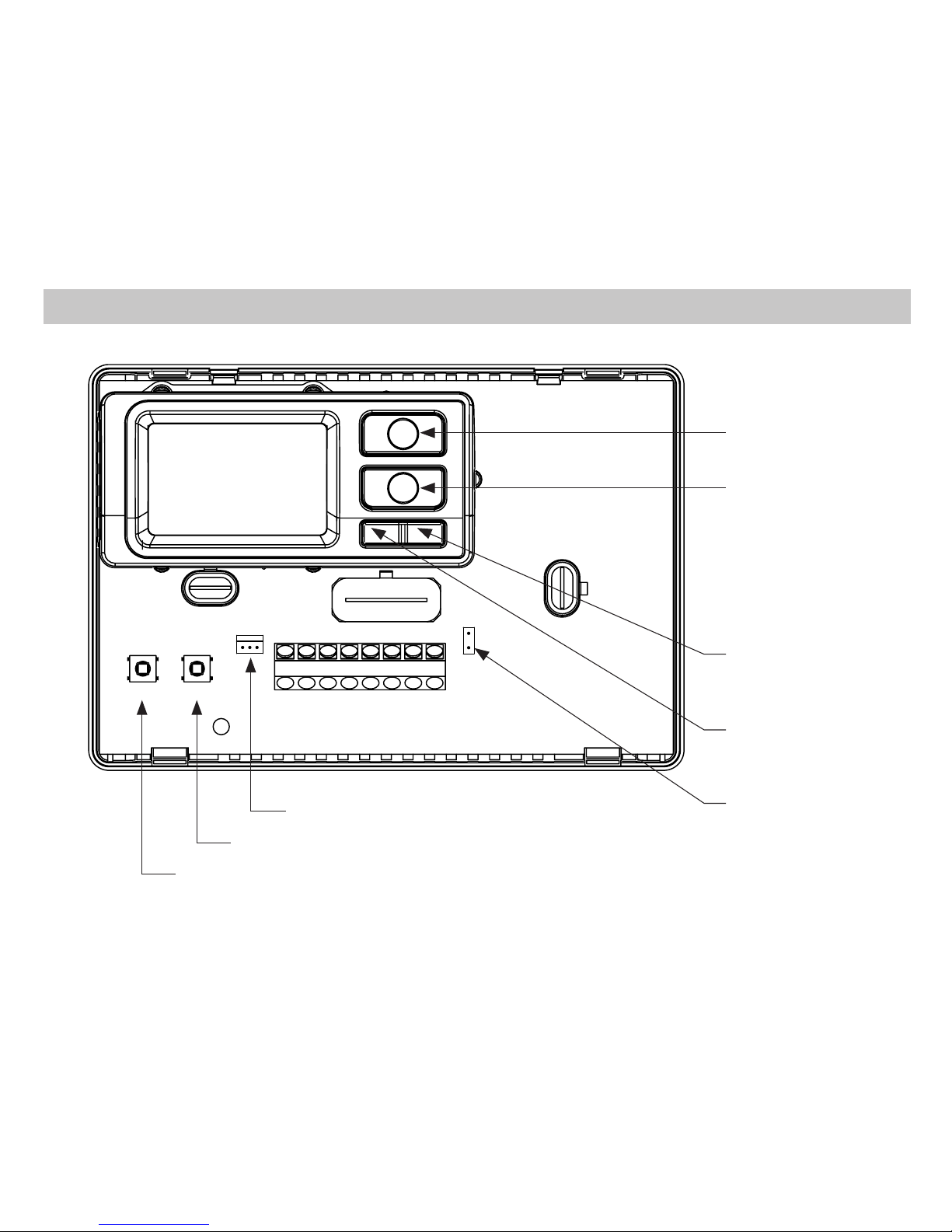
Parts Diagram
Configuration switch
Reset switch
Left (system)
button
Right (fan)
button
Down button
Up button
Field programming pins
RC/RH Jumper
FP
2
Specications
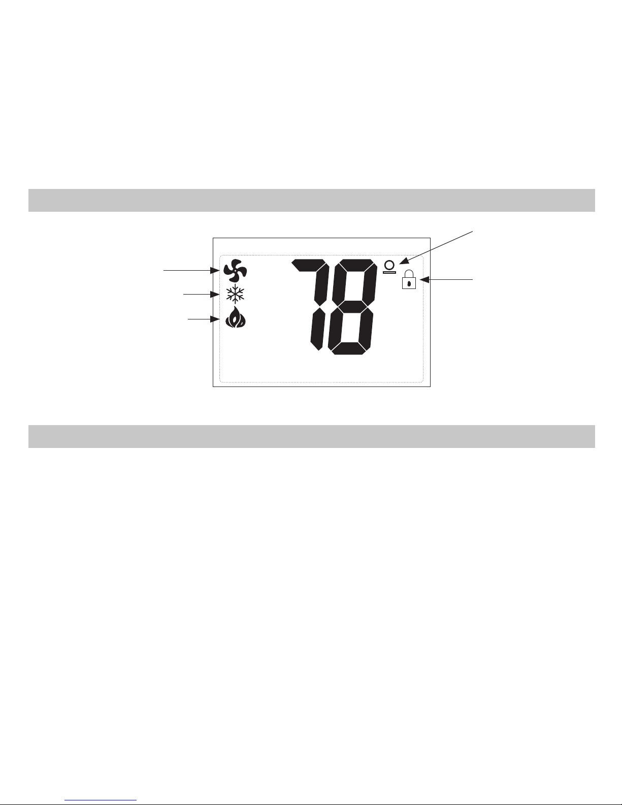
Icon Descriptions
Fan operation icon
Cooling operation icon
Heating operation icon
Lock mode
activated
Room
temperature
offset activated
Electrical rating: • 24 VAC (18-30 VAC)
• 1 amp maximum per terminal
• 3 amp maximum total load
Temperature control range: 45°F to 90°F (7°C to 32°C) Accuracy: ± 1°F (± 0.5°C)
System configurations: 1-stage heat, 1-stage cool, heat pump, gas, oil, electric
Timing:
Anti-short Cycle:
4 minutes
Backlight Operation
Terminations: S1, S2, Y, W/O/B, G, RC, RH, C
3
Package Contents/Tools Required
Package includes: SimpleComfort® PRO 5011 thermostat on base, thermostat cover, wiring labels,
screws and wall anchors, Installation, Operation and Application Guide
Tools required for installation: Drill with 3/16” bit, hammer, screwdriver
Important Safety Information
WARNING!
:
Always turn off power at the main power supply before installing, cleaning, or
removing thermostat.
• This thermostat is for 24 VAC applications only; do not use on voltages over 30 VAC
• Do not short across terminals of gas valve or system control to test operation; this will damage your
thermostat and void your warranty
• All wiring must conform to local and national electrical and building codes
• Do not use air conditioning when the outdoor temperature is below 50 degrees; this can damage your
A/C system and cause personal injuries
• Use this thermostat only as described in this manual
To Remove Existing Thermostat
ELECTRICAL SHOCK HAZARD
– Turn off power at the main service panel by removing the fuse
or switching the appropriate circuit breaker to the OFF position before removing the existing
thermostat.
1. Turn off power to the heating and cooling system by removing the fuse or switching the appropriate
circuit breaker off.
2. Remove cover of old thermostat. This should expose the wires.
3. Label the existing wires with the enclosed wire labels before removing wires.
4. After labeling wires, remove wires from wire terminals.
5. Remove existing thermostat base from wall.
6. Refer to the following section for instructions on how to install this thermostat.
4
To Install Thermostat
ELECTRICAL SHOCK HAZARD
– Turn off power at the main service panel by removing the fuse
or switching the appropriate circuit breaker to the OFF position before removing the existing
thermostat.
IMPORTANT: Thermostat installation must conform to local and national building and electrical
codes and ordinances.
Note: Mount the thermostat about five feet above the floor. Do not mount the thermostat on an
outside wall, in direct sunlight, behind a door, or in an area affected by a vent or duct.
1. Turn off power to the heating and cooling system by removing the fuse or switching the
appropriate circuit breaker off.
2. To remove cover, pull gently at the seam at the top.
3. Put thermostat base against the wall where you plan to mount it (Be sure wires will feed through
the wire opening in the base of the thermostat).
4. Mark the placement of the mounting holes.
5. Set thermostat base and cover away from working area.
6. Using a 3/16” drill bit, drill holes in the places you have marked for mounting.
7. Use a hammer to tap supplied anchors in mounting holes.
8. Align thermostat base with mounting holes and feed the control wires through slit in thermal
intrusion barrier and into wire opening.
9. Use supplied screws to mount thermostat base to wall.
10. For 2 transformer systems, remove and discard RC/RH jumper.
11. Insert stripped, labeled wires in matching wire terminals.
CAUTION!: Be sure exposed portion of wires does not touch other wires.
12. Gently tug wire to be sure of proper connection. Double check that each wire is connected to the
proper terminal.
13. Turn on power to the system at the main service panel.
14. Configure thermostat (see Page 12) to match the type of system you have.
15. Replace cover on thermostat by snapping it in place.
16. Test thermostat operation as described in “Testing the Thermostat” (Page 19).
5
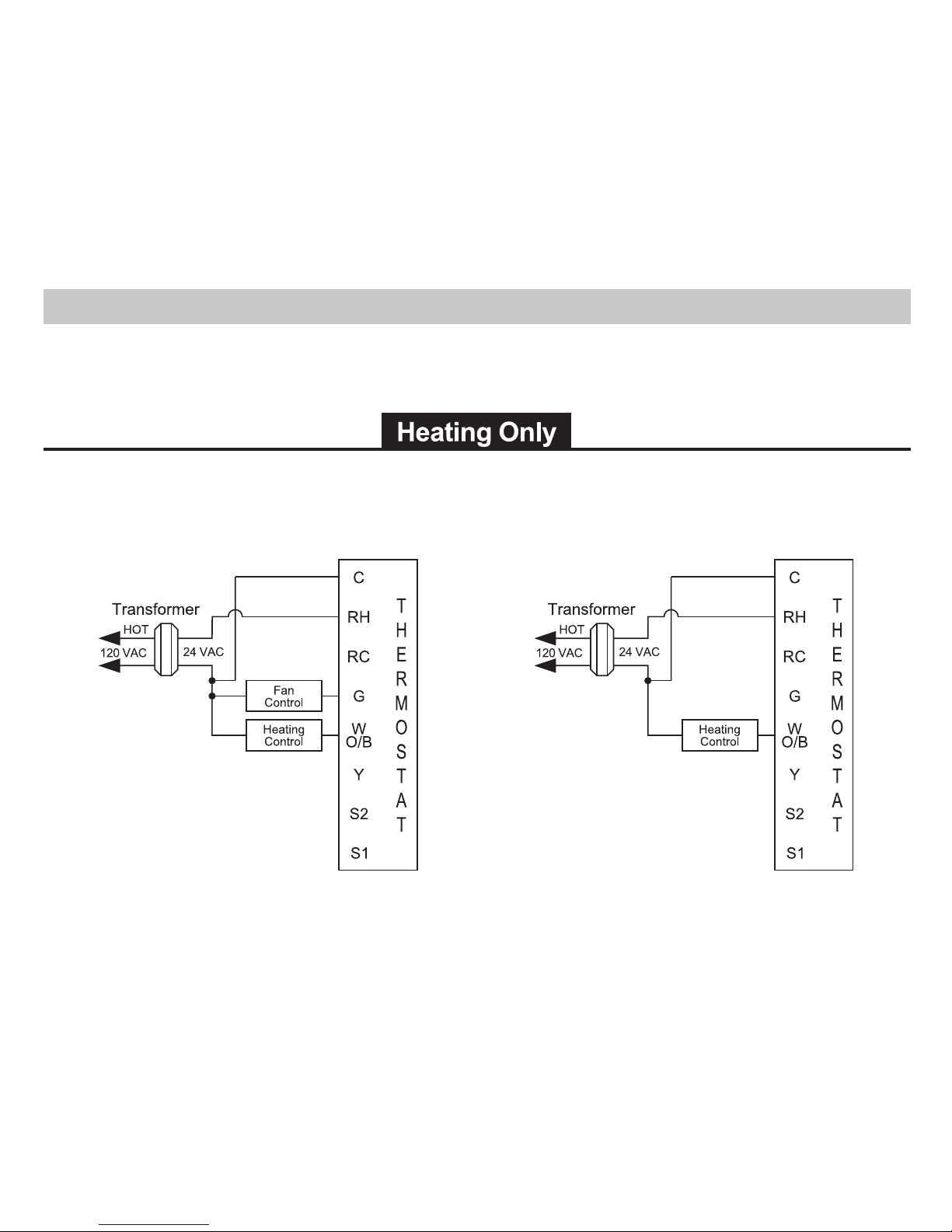
Hardwired
3-Wire, Single Transformer
Hardwired
4-Wire, Single Transformer
Wiring Diagrams
6
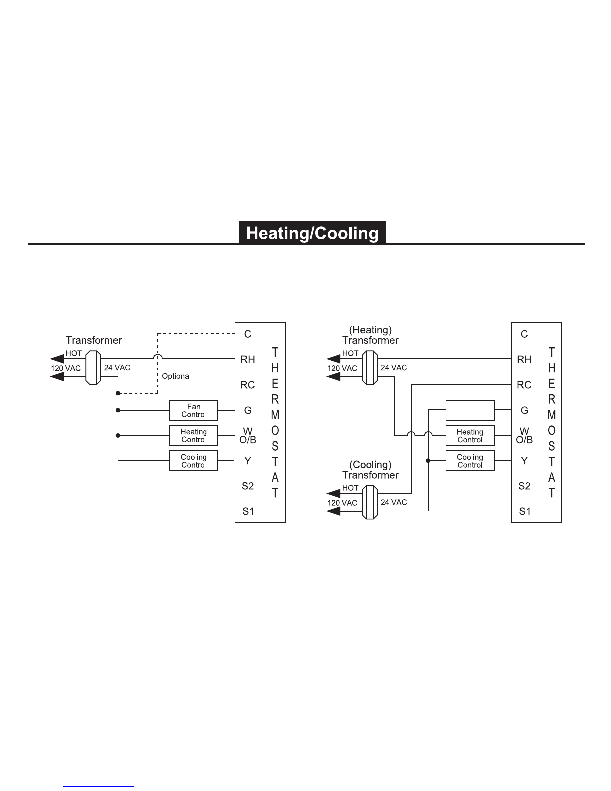
Hardwired
5-Wire, Two Transformer
(Both transformers must be in phase)
Hardwired
4 or 5-Wire, Single Transformer
Fan
Control
IMPORTANT: Before wiring, remove pre-installed
RC/RH jumper.

7
Hardwired
Cool or Heat Active Reversing Valve
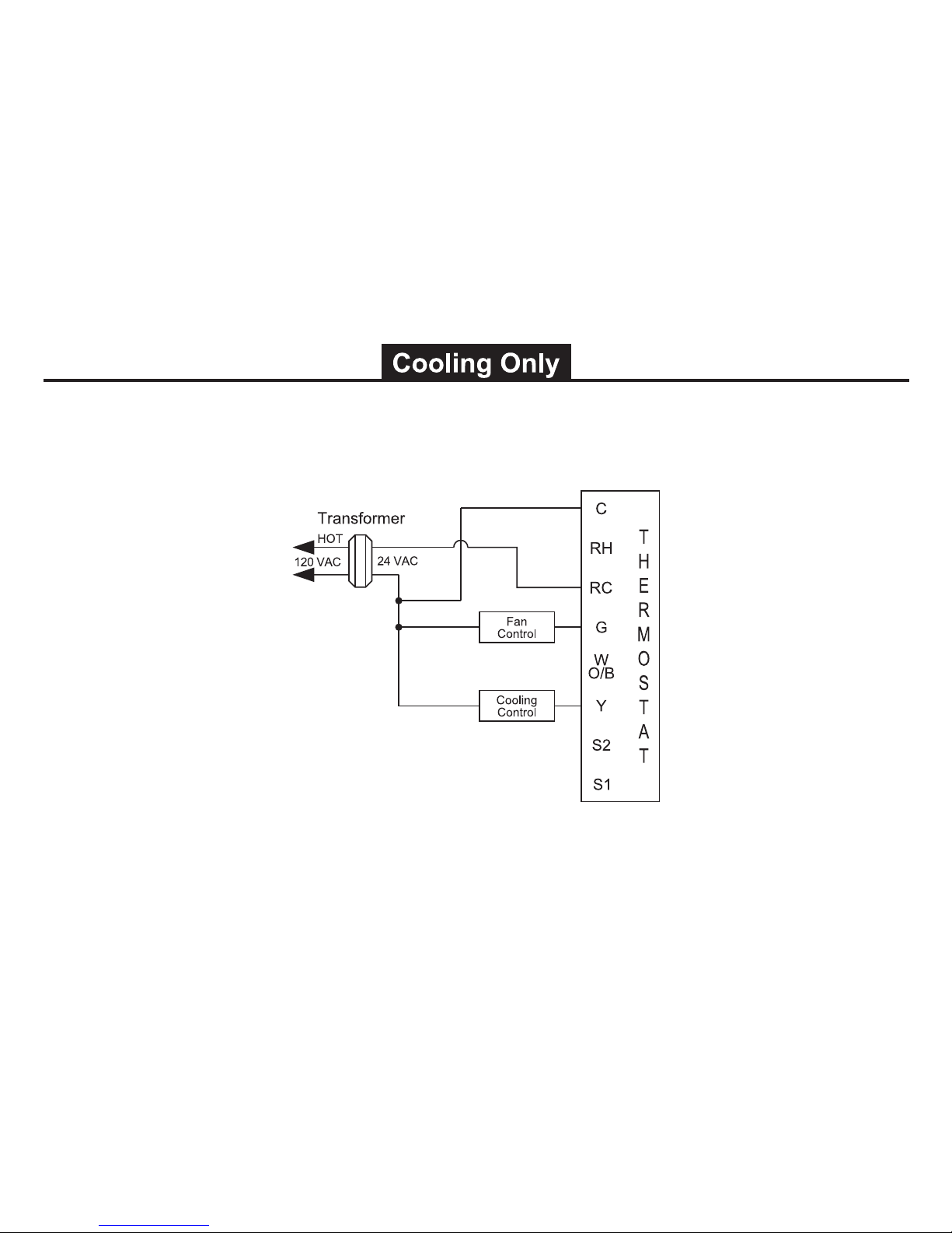
8
Hardwired
4-Wire, Single Transformer
 Loading...