


ICM271
Fan Control
SEC-2
C15
R23
R17
R24
D2
R25
G
BLOWER OPTION
TEST
R7
R14
R20
R13
R12
GAS3
GAS1
ATO 3-amp Fuse
Center
SEC-1
LIM-2
LIM-1
GAS2
W4
W3
P4
1
C8W5C8
C8
C8
3 AMP
Blower
Option
Vent
Damper
Plug
Connection
Vent
Damper
ICM271
Replacement Description
The ICM271 Fan Control Center is a solid state control designed and
engineered for the replacement market. The ICM271 is designed specically
to replace the Carrier/BDP Gas Furnace Control Centers that have been
used in new equipment for many years. The ICM271 is a form, t and
functional replacement of the OEM control requiring no modications to the
original wiring or to the appliance’s sheet metal.
The ICM271 is a form, t and functional replacement of the OEM control for
the following Carrier/BDP part numbers:
302075-3 HH84AA010 HH84AA013
CES0110017 HH84AA011 HH84AA020
CES0110018 HH84AA012 P771-7002
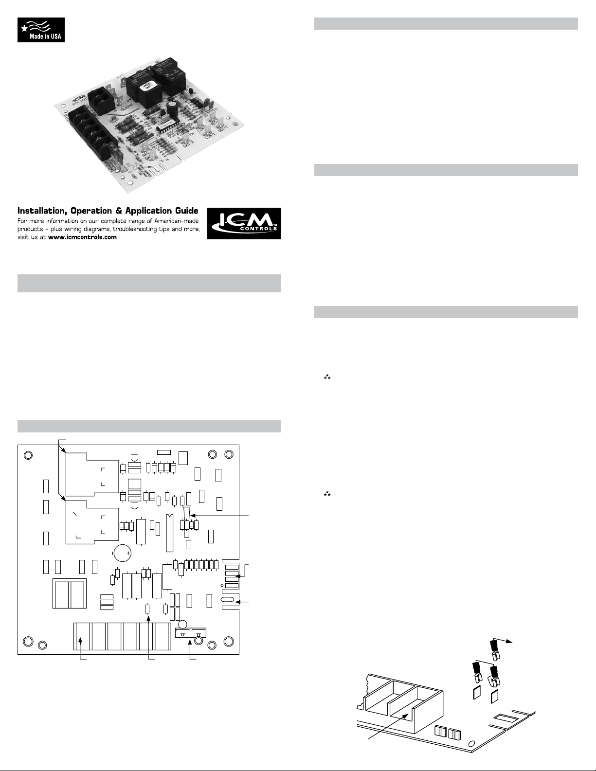
ICM271 Component Layout
SPCB-1
PCB500-1
L2 L1 PR-1
PR-2
COM
1
EAC-2 EAC-1
Blower Relays
NO
C
NC
NO
C
FROM-C
HI
LO
P2
P1
Wall Thermostat
Terminal Block
COILCOIL
Q2
K1
CR7
C7 C6
C5 C2
CR6
C4
K2
Q1
R1
R2
D1
Z1
C3
R15
R8
R9
W2
C10
C11
C12
JW-1
RGH WGCYC
RGH WGCYC
C1
M1
CR4
CR2
CR1
CR3
R5
R6
R3
CR5
R4
R21
U1
R22
C16
R11
R16
R18
R10
R19
C13
C9
W6
C8
C14
61
F1
JW-1
Specifications
• Input Voltage
- Terminals: PR-1, PR-2, L1 and L2 ...............................................120 VAC
- Terminals: SEC-1 and SEC-2 ...................................................18-30 VAC
• Line Frequency ..................................................................................60 Hz
• Operating Temperature .....................................................-40ºF to +176ºF
• Maximum Operating Humidity ...................................................95% R.H.
Non-condensing @ 50ºC
• Time Delays
- Heat ON .................................................................................. 75 Seconds
- Heat OFF .............................................................................. 105 Seconds
- Cool OFF ................................................................................ 90 Seconds
Pre-Installation Instructions
• Turn off gas supply and electrical power to equipment before servicing
CAUTION!
: This device should be installed by a qualied technician
with due regard for safety as improper installation could
result in hazardous conditions.
CAUTION!
: Failure to carefully read and follow these instructions
before servicing or operating this control, could result in
personal injury, death and/or property damage.
CAUTION!
: Do not short out terminals on the gas valve or the
ignition control module. A short or incorrect wiring will
burn out the thermostat heat anticipator. It could also
result in personal injury, death and/or property damage.
Operational Differences
The ICM271 has the same features and functions as the current Carrier/
BDP replacement (HH84AA020). The ICM271 has additional optional
features and some slight operational differences than the older obsolete
Carrier/BDP units. These options and operational differences are listed
below.
Note: Some older Carrier models did not have a cooling fan relay.
1. On older Carrier/BDP models, the low-speed blower would still function
if the 24 volt transformer malfunctions. This will not happen with the
ICM271.
2. If the JW1 jumper is cut, a constant low-speed blower will occur without
any thermostat signal. Also, a signal applied to the GC or Y terminals will
not bring on the hi-speed blower during the cooling mode. Therefore, the
JW1 jumper must not be cut on cooling applications.
3. The 24 volt circuit is fuse protected which is not true on earlier Carrier/
BDP models. A 3 amp automotive type fuse is used to protect the
thermostat and transformer circuits from shorts.
Note: On the ICM271, a blown fuse will cause the lo-speed blower to
4. The ICM271 has an easy-to-remove vent damper jumper plug. This
jumper plug is factory assembled for use on applications not having a
vent damper. If the application has a vent damper, remove the jumper
plug and connect the vent damper wiring harness connector to the
ICM271 circuit board.
The GAS1-to-GAS3 connection is made by a three-wire ame-proof
switch, but in some standing-pilot applications this device is not present. In
such applications, a jumper must be installed between GAS1 and GAS3
terminals.
A jumper should only be used on applications where a jumper exists on the
previous furnace fan control board. This jumper should also include a male
1/4” spade connector to connect to your current gas valve’s wiring harness.
come on and remain on until the fuse has been replaced.
To
Gas
Valve
W
GAS3
GAS1
 Loading...