

ICM Controls SC3211L Installation, Operation & Application Manual
16 19
17 20
18
1
2
3
ONE-YEAR LIMITED WARRANTY
The Seller warrants its products against defects in material or workmanship for a period of one (1) year from the
date of manufacture. The liability of the Seller is limited, at its option, to repair, replace or issue a non-case credit for
the purchase prices of the goods which are provided to be defective. The warranty and remedies set forth herein
do not apply to any goods or parts thereof which have been subjected to misuse including any use or application
in violation of the Seller’s instructions, neglect, tampering, improper storage, incorrect installation or servicing not
performed by the Seller. In order to permit the Seller to properly administer the warranty, the Buyer shall: 1) Notify
the Seller promptly of any claim, submitting date code information or any other pertinent data as requested by the
Seller. 2) Permit the Seller to inspect and test the product claimed to be defective. Items claimed to be defective
and are determined by Seller to be non-defective are subject to a $30.00 per hour inspection fee. This warranty
constitutes the Seller’s sole liability hereunder and is in lieu of any other warranty expressed, implied or statutory.
Unless otherwise stated in writing, Seller makes no warranty that the goods depicted or described herein are t for
any particular purpose.
LIAF020
Patent No. - Design: 424,953
Patent No. - Thermal Intrusion Barrier: 6,597,275
Patent Pending - SimpleSet
TM
Target Programming Technology
7313 William Barry Blvd., North Syracuse, NY 13212
(Toll Free) 800-365-5525 (Phone) 315-233-5266 (Fax) 315-233-5276
www.icmcontrols.com
Table of Contents
To Install Thermostat
ELECTRICAL SHOCK HAZARD
– Turn off power at the main service panel by removing the fuse
or switching the appropriate circuit breaker to the OFF position before removing the existing
thermostat.
IMPORTANT: Thermostat installation must conform to local and national building and electrical codes and
ordinances.
Note: Mount the thermostat about ve feet above the oor. Do not mount the thermostat on an outside wall, in
direct sunlight, behind a door, or in an area affected by a vent or duct.
1. Turn off power to the heating and cooling system by removing the fuse or switching the appropriate circuit
breaker off.
2. To remove cover, insert and twist a coin or screwdriver in the slots on the top corner of the thermostat.
3. Put thermostat base against the wall where you plan to mount it (Be sure wires will feed through the wire opening
in the base of the thermostat).
4. Mark the placement of the mounting holes.
ELECTRICAL SHOCK HAZARD
– Turn off power at the main service panel by removing the fuse
or switching the appropriate circuit breaker to the OFF position before removing the existing
thermostat.
1. Turn off power to the heating and cooling system by removing the fuse or switching the appropriate circuit
breaker off.
2. Remove cover of old thermostat. This should expose the wires.
3. Label the existing wires with the enclosed wire labels before removing wires.
4. After labeling wires, remove wires from wire terminals.
5. Remove existing thermostat base from wall.
6. Refer to the following section for instructions on how to install this thermostat.
To Remove Existing Thermostat
2-Stage H eat/ 2-Stage Coo l
Manual Ch angeover
Hardwired
SC3211L
Progra mmable Elect ronic Thermo stat
Installation, Operation & Application Guide
For more information on our complete range of American-made
products – plus wiring diagrams, troubleshooting tips and more,
visit us at www.icmcontrols.com
Specications ...............................................................................................................................................................1
Important Safety Information ........................................................................................................................................1
Package Contents/Tools Required ...............................................................................................................................1
To Remove Existing Thermostat ...................................................................................................................................2
To Install Thermostat ....................................................................................................................................................2
Wiring Diagrams ...........................................................................................................................................................4
Single Compressor, Cool Active .................................................................................................................................4
Dual Compressor, Cool Active ....................................................................................................................................4
Single Compressor, Heat Active .................................................................................................................................5
Dual Compressor, Heat Active....................................................................................................................................5
Parts Diagram...............................................................................................................................................................6
Operation ......................................................................................................................................................................6
Setting the Setpoint Temperature .................................................................................................................................6
Conguration Mode ......................................................................................................................................................7
Conguration Mode Settings ........................................................................................................................................8
Starting the Thermostat ..............................................................................................................................................11
Testing the Thermostat ...............................................................................................................................................12
Operating Modes ........................................................................................................................................................13
Setting the Time and Day of the Week .......................................................................................................................14
Programming ..............................................................................................................................................................15
Lockout Feature..........................................................................................................................................................16
Factory Preprogramming ............................................................................................................................................17
Personal Program Schedule.......................................................................................................................................17
SimpleSetTM Field Programming...............................................................................................................................19
Troubleshooting ..........................................................................................................................................................20
Specifications
Electrical rating:
• 18-30 VAC
• 1 amp maximum per terminal
• 4 amp maximum total load
Temperature control range: 45°F to 90°F (7°C to 32°C) Accuracy: ± 1°F (± 0.5°C)
System congurations: 2-stage heat, 2-stage cool, heat pump
Terminations: R, C, Y1, Y2, W2, O, B, G, L, E
Important Safety Information
WARNING!
:
Always turn off power at the main power supply before installing, cleaning, or removing
thermostat.
• This thermostat is for 24 VAC applications only; do not use on voltages over 30 VAC
• All wiring must conform to local and national electrical and building codes
• Do not use air conditioning when the outdoor temperature is below 50 degrees; this can damage your A/C system
and cause personal injuries
• Use this thermostat only as described in this manual
Package Contents/Tools Required
Package includes: SimpleComfort® SC3211L thermostat on base, thermostat cover, wiring labels, screws and wall
anchors, Installation, Operation and Application Guide.
Tools required for installation: Drill with 3/16” bit, hammer, screwdriver.
5. Set thermostat base and cover away from working area.
6. Using a 3/16” drill bit, drill holes in the places you have marked for mounting.
7. Use a hammer to tap supplied anchors in mounting holes.
8. Align thermostat base with mounting holes and feed the control wires through wire opening.
9. Use supplied screws to mount thermostat base to wall.
10. Insert stripped, labeled wires in matching wire terminals. See “Wiring Diagrams” section of this manual
(Pages 4-5).
CAUTION!: Be sure exposed portion of wires does not touch other wires.
11. Gently tug wire to be sure of proper connection. Double check that each wire is connected to the proper
terminal.
12. Replace cover on thermostat by snapping it in place.
13. Turn on power to the system at the main service panel.
14. Test thermostat operation as described in “Testing the Thermostat” (Page 12).
Lockout Feature
From any of the screens on Page 15, you can press the HOLD (right) button to begin entering your program
schedule. The days shown on the display will all be programmed simultaneously.
Once the HOLD (right) button is pressed, MORN blinks.
Use the up or down button to select a different period (MORN, DAY, EVE, NITE).
Press HOLD (right) button to advance to the next screen. Transition time hour blinks.
Use the up or down button to select a different hour.
Press HOLD (right) button to advance to the next screen. Transition time minutes blink.
Use the up or down button to select different minutes.
Press HOLD (right) button to advance to the next screen. Heat set temperature displays.
Use the up or down button to adjust the heat set temperature.
Press HOLD (right) button to advance to the next screen. Cool set temperature displays.
Use the up or down button to adjust the cool set temperature.
Repeat above steps to program the four periods per day.
When the program schedule is complete, press and hold the PROG and HOLD buttons (pressed simultaneously) in
for 2 seconds to return to the OFF mode.
The SC3211L has a button lockout feature so the mode cannot be changed and the
temperature adjustment is limited. Select the appropriate lockout from Conguration
Mode Settings (Step 6, Page 9) of this guide.
To activate the LOC feature:
1. Simultaneously press the PROG, HOLD and UP buttons for 10 seconds.
2. LOC will display and the lockout function will be enabled.
To deactivate the LOC feature, repeat steps 1 and 2 above.
Factory Preprogramming
MORN 6:00 AM DAY 8:00 AM EVE 6:00 PM NITE 10:00 PM
HEAT 70°F HEAT 62°F HEAT 70°F HEAT 62°F
COOL 78°F COOL 85°F COOL 78°F COOL 82°F
MONDAY
thru
SUNDAY
Personal Program Schedule
MORN DAY EVE NITE
HEAT HEAT HEAT HEAT
COOL COOL COOL COOL
MONDAY
1
MORN DAY EVE NITE
HEAT HEAT HEAT HEAT
COOL COOL COOL COOL
MORN DAY EVE NITE
HEAT HEAT HEAT HEAT
COOL COOL COOL COOL
WEDNESDAY
3
TUESDAY
2
The SC3211L comes preprogrammed with the following schedule:
Use the following personal program schedule to record your settings:
MORN DAY EVE NITE
HEAT HEAT HEAT HEAT
COOL COOL COOL COOL
THURSDAY
4
MORN DAY EVE NITE
HEAT HEAT HEAT HEAT
COOL COOL COOL COOL
FRIDAY
5
MORN DAY EVE NITE
HEAT HEAT HEAT HEAT
COOL COOL COOL COOL
MORN DAY EVE NITE
HEAT HEAT HEAT HEAT
COOL COOL COOL COOL
SUNDAY
7
SATURDAY
6
SimpleSetTM Field Programming
This feature is used for transferring conguration and program schedule from the master to the target thermostat.
All thermostats for a job can be mounted and powered up. Congure and program one thermostat. This will be the
master. The master will be used to copy the program to the rest of the thermostats.
Preparing the master to Send:
1. The master must be powered by 24 VAC.
2. Verify the master thermostat is in OFF mode. Slide system switch to center position.
3. Remove cover of the master thermostat by gently pulling near one of the corners at the top
of the thermostat.
4. Press the up and down buttons and CONFIG switch simultaneously for 5 seconds.
5. The OUT screen displays indicating the master thermostat is ready to
transfer data.
Note: Press the up and down buttons and CONFIG switch simultaneously for 5 seconds
to exit from data transfer mode and to return the master to the OFF mode.
6. Connect the master to the target using the 3 wire connector. Attach one end to the Master’s
FP pins and the other end to the Target’s FP pins.
Note: Target thermostat must be powered by 24 VAC for eld programming to occur
When the connection has been made correctly, the master thermostat will power up and the target will count from 6
down to 1. It will then display LOC conrming the data has been saved in memory.
When all target thermostats have been completed, reinstall the master thermostat.
Press the up and down buttons and the CONFIG switch simultaneously for 5 seconds to exit from the data transfer
mode and to return the master thermostat to the OFF mode.
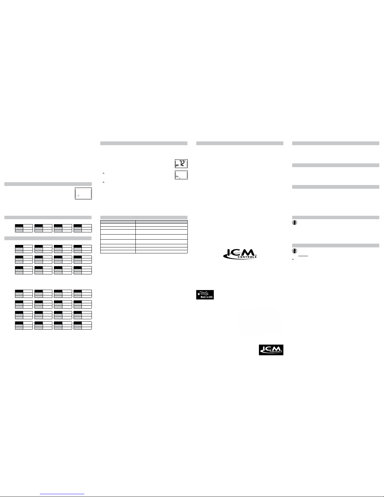
OFF
Troubleshooting
* Reset Button Function:
Time, day and program/non-program changed to last saved settings (saved after
program or conguration change), conguration and program unchanged, ASC timer
reset to 0.
Symptom Remedy
No display Verify 24 VAC is at thermostat
System fan does not come on properly Verify wiring is correct
Program schedule activates at the wrong
time
Check time (AM/PM) set on thermostat (see “Setting the Time,”
Page 14)
Thermostat turns on and off too frequently Adjust temperature differential (see “Conguration Mode Settings,”
Page 8)
Thermostat does not follow program Verify it is operating in Program mode (PROG solid in display);
check time (AM/PM); check if in Hold mode (PROG ashes)
“PROGram” ashes (in Hold mode) Press Hold button to remove from Hold mode (PROG solid)
Fan runs continuously Check Fan Auto/On switch, continuous fan operation in ON
Problem not listed above Press reset button once*
• 7-Day Programmable
•
2-Stage Heat Pump
•
Manual Changeover
•
SimpleSet
®
Target Programming
•
Selectable °F or °C
•
Relay Outputs
(minimum voltage drop in thermostat)
•
Ideally Suited for Residential
–
Residential (New Construction/Replacement),
Light Commercial
4 7
5 8
6 9
10
11
12
13
14
15
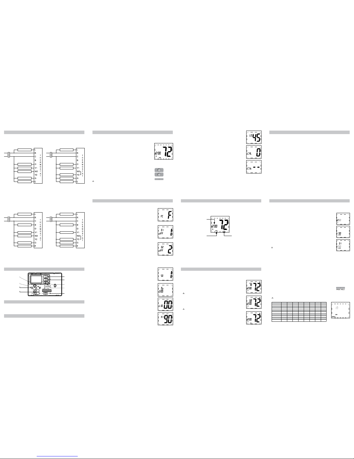
Wiring Diagrams
Single Compressor
Cool Active
Heat Pump – with electric backup
Dual Compressor
Cool Active
Heat Pump
Note: For systems without emergency strip heat, a jumper wire should be placed between W2 & E.
Transformer
120
VAC
24 VAC
Reversing Valve
Compressor
Auxiliary Heat
Service Led Wire
Emergency Heat
Fan
Compressor #2
Transformer
120
VAC
24 VAC
Reversing Valve
Compressor #1
Service Led Wire
Emergency Heat
Fan
NOTE: Place jumper between W2 and Y2
Single Compressor
Heat Active
Heat Pump – with electric backup
Dual Compressor
Heat Active
Heat Pump
Note: For systems without emergency strip heat, a jumper wire should be placed between W2 & E.
Transformer
120
VAC
24 VAC
Reversing Valve
Compressor
Auxiliary Heat
Service Led Wire
Emergency Heat
Fan
Compressor #2
Transformer
120
VAC
24 VAC
Reversing Valve
Compressor #1
Service Led Wire
Emergency Heat
Fan
NOTE: Place jumper between W2 and Y2
Operation
Setting the Setpoint Temperature
Parts Diagram
Reset switch
Conguration switch
Mode switch
Up button
Down button
Fan switch
Left (PROG) button
Right (HOLD) button
Field programming pins
The SimpleComfort® SC3211L thermostat has buttons that are used to:
• Adjust the setpoints of the thermostat • Set the operation mode • Program the schedule
• Enter vacation Hold • Reset the thermostat • Activate the program feature
1. With the system switch in Heat, Emergency Heat or Cool, the current temperature setpoint displays.
2. Press the up or down button until the desired temperature setpoint displays.
3. The new temperature setpoint is automatically saved in memory.
6. Lockout (0°F-8°F) (0°C-4°C) – Select the number of degrees set
temperature can be changed during keypad lockout
Press the up or down button to select.
Press the right button to advance to the next screen.
7. Maximum Heat Setpoint (45°F to 90°F) (7°C to 32°C)
Adjust to control the maximum heat set temperature allowed.
Press the up or down button to select.
Press the right button to advance to the next screen.
5. Auxiliary Delay ON – (0-30 minutes) – Set the delay time in minutes for auxiliary
heat to be locked out after a call for second stage. This extra savings feature is
used to temporarily lock out auxiliary heat devices, allowing just heat pump to try to
satisfy heat call.
Press the up or down button to select.
Press the right button to advance to the next screen.
4. Staged Off Outputs
Select whether the outputs for heating and cooling are staged off independently or
are satised simultaneously.
1 = outputs staged off independently
0 = outputs off simultaneously
Press the up or down button to set.
Press the right button to advance to the next screen.
Configuration Mode Settings
The setup screens for Conguration Mode are as follows:
1. Temperature Scale (F or C) – Choose Fahrenheit or Celsius.
Press the up or down button to select.
Press the
right
button to advance to the next screen.
3. 2nd Stage Temperature Differential (1°F to 5°F) (1°C to 3°C)
Set the number of degrees between when stage 1 turns on and when stage 2 turns
on.
Press the up or down button to set differential value.
Press the right button to advance to the next screen.
2. 1st Stage Temperature Differential (1°F to 5°F) (1°C to 3°C)
Set the number of degrees between your “setpoint” temperature and your “turn on”
temperature.
Press the up or down button to set differential value.
Press the right button to advance to the next screen.
Configuration Mode
1. Verify the SC3211L is in the OFF mode.
Slide the system switch until off mode displays.
2. Remove the cover of the thermostat by gently pulling near one of the corners at
the top of the thermostat.
3. Press the CONFIG button for 1 second while the SC3211L is in OFF mode.
To exit conguration mode, press the CONFIG switch for 1 second or slide
the mode switch to heat or cool.
Press the up or down button to change settings within each screen.
Down
button
Up
button
Press the right button to advance to the next screen.
Note: Pressing the
left
button will return you to the previous screen.
Left
button
Right
button
The conguration mode is used to set the SC3211L to match your heat pump system.
To congure the SC3211L, perform the following steps:
8. Minimum Cool Setpoint (45°F to 90°F) (7°C to 32°C)
Adjust to control the minimum cool set temperature allowed.
Press the up or down button to select.
Press the right button to advance to the next screen.
9. Room Temperature Offset (+9°F to -9°F) (+5°C to -4°C)
Adjust to calibrate displayed room temperature to match actual room temperature.
Press the up or down button to select.
Press the right button to advance to the next screen.
10. Maximum Cycles Allowed Per Hour (- -, 2-6)
- - = as many as needed, 2-6 = maximum cycles/hour
Press the up or down button to select.
To exit conguration mode, press the conguration button for 2 seconds or slide the
mode switch to heat or cool.
Starting the Thermostat
CAUTION!
: Do not use air conditioning when the outdoor temperature is below 50 degrees. This can damage
your air conditioning system and cause personal injuries.
1. Move the Fan Auto/On switch to the Auto position.
2. Move the Cool/Off/Heat switch to Cool or Heat, depending on the season.
Room Temperature
OFF Indicator
Time
Testing the Thermostat
Once the thermostat is installed, it should be thoroughly tested.
CAUTION!
: Do not energize the air conditioning system when the outdoor temperature is below 50 degrees. It
can result in equipment damage or personal injury.
Cool Test
1. Slide system switch to Cool position. Cool mode screen is displayed.
2. Adjust set temperature so it is 5 degrees below room temperature.
3. Air conditioning should come on within a few seconds.
4. Adjust the set temperature 2 degrees above the room temperature and the A/C should
turn off. There may be a fan delay on your system.
Note: There is a four minute delay to protect your compressor.
Heat Test
1. Slide system switch to Heat position. Heat mode screen is displayed.
2. Adjust the set temperature so it is 5 degrees above the room temperature.
3. Heat should come on within a few seconds.
4. Adjust the set temperature so it is 2 degrees below the room temperature and the
heat should turn off. There may be a fan delay on your system.
Note: There is a four minute delay to protect your compressor.
Fan Test
1. Slide Fan switch to On position.
2. Indoor fan turns ON.
3. Slide Fan switch to Auto position.
4. Indoor fan turns OFF.
Operating Modes
OFF Mode
• In this mode, the thermostat will not turn on the heating or cooling devices (manual fan can operate)
• OFF mode is also used to access setup and the program schedule
Cool Mode
• In this mode, the thermostat controls the cooling system
• Press the PROG button to enter and exit Program Cool mode
• In Program Cool (PROG solid on display) mode, the thermostat will follow the program schedule that is stored in
memory
Heat Mode
• In this mode, the thermostat controls the heating system
• Press the PROG button to enter or exit the Program Heat mode
• In Program Heat (PROG solid on display) mode, the thermostat will follow the program schedule that is stored in
memory
Emergency Heat Mode
• In this mode, the thermostat controls the heating system and the heat pump is disabled
• Press the PROG button to enter or exit the Program Emergency Heat mode
• In Program Emergency Heat (PROG solid on display) mode, the thermostat will follow the program schedule that
is stored in memory
Hold Functions
When in Programmable Cool, Programmable Heat or Programmable Emergency Heat, you can lock in the
present settings indenitely by pressing the Hold button once (PROG ashes). Press Hold button again to exit Hold
mode (PROG solid). For a temporary hold period, raise or lower set temperature to desired set temperature. The
thermostat will automatically return to programmed set temperature after 2 hours.
Setting the Time and Day of the Week
2. Press and hold the PROG button (left) and HOLD (right) buttons (simultaneously) in for 6 seconds.
1. Slide the system switch to the OFF position. You are in the OFF mode.
The time and day of the week must be set for your program schedule to operate correctly.
5. Press the HOLD (right) button once to select day of the week (TODAY ashing).
Press the up or down button to select current day of the week
(01/Monday, 02/Tuesday, etc.).
Note: At any time, press the PROG (left) button to return to the previous screen or
press the HOLD (right) button to advance to the next screen.
Press the PROG button and HOLD button (simultaneously) in for 2 seconds to lock
values into memory and return to the OFF mode or press the HOLD (right) button once
to enter programming.
4. Press the HOLD (right) button once to select minutes (minutes ashing).
Press the up or down button to adjust the minutes.
3. Time displays (hour ashing).
Press the up or down button to adjust the hour.
Setting the program schedule:
1. Slide the system switch to the center position. You are in OFF mode.
2. Press and hold the PROG and HOLD buttons (pressed simultaneously) for 6 seconds.
3. Press the HOLD (right) button 3 times.
4. Day 1-7 are blinking.
From this screen you have 2 options:
1. Press the HOLD (right) button to begin programming all 7 days at one time, or
2. Press the
up
button to see the other programming options.
Note: The days of the week shown on the display will be programmed simultaneously.
The screens are listed below.
Screen 1 1-7 SUN MON TUE WED THU FRI SAT
Screen 2 1-5 MON TUE WED THU FRI
Screen 3 01 MON
Screen 4 02 TUE
Screen 5 03 WED
Screen 6 04 THU
Screen 7 05 FRI
Screen 8 6-7 SUN SAT
Screen 9 06 SAT
Screen 10 07 SUN
Program Overview
The SC3211L programmable thermostat has four periods (MORN, DAY, EVE, NITE) that are customizable for each
day of the week. Each period will have a start time, heat temperature, and cool temperature. The SC3211L monitors
the day and time, while maintaining the specic conditions you have chosen for each period in your program.
 Loading...