

ICM Controls SC 3201 Installation and Operation Manual
Heat Pump
7-Day Programmable
Hardwired
SC 3201
Programmable Electronic Thermostat
Installation, Operation & Application Guide
For more information on our complete range of American-made
products – plus wiring diagrams, troubleshooting tips and more,
visit us at www.icmcontrols.com
• 7-Day Programmable
• 2-Stage Heat Pump
• Backlit Display
• Manual Changeover
• Simpleset® Programming
• Title 24 Compliant / No Batteries Required
• Relay Outputs
(minimum voltage drop in thermostat)
• Ideally Suited for:
–
Residential (New Construction/Replacement),
Light Commercial

Table of Contents
SimpleComfort® 3201 Parts Diagram .......................................................................................... 1
Specifications
.............................................................................................................................. 2
Important Safety Information ..................................................................................................... 2
Package Contents/Tools Required ............................................................................................... 2
To Remove Existing Thermostat ................................................................................................ 3
To Install Thermostat .................................................................................................................. 3
Wiring Diagram Conversions .................................................................................................. 5-16
Mode of Operation .................................................................................................................... 17
LED Indicators .......................................................................................................................... 18
Starting the Thermostat ........................................................................................................... 19
Testing the Thermostat ............................................................................................................ 20
Operating Modes ...................................................................................................................... 22
Setting the Time and Day of the Week ..................................................................................... 23
Programming
............................................................................................................................ 24
Simpleset
®
Programming .......................................................................................................... 26
Factory Preprogramming .......................................................................................................... 26
Personal Program Schedule ...................................................................................................... 27
Troubleshooting
........................................................................................................................ 29
1
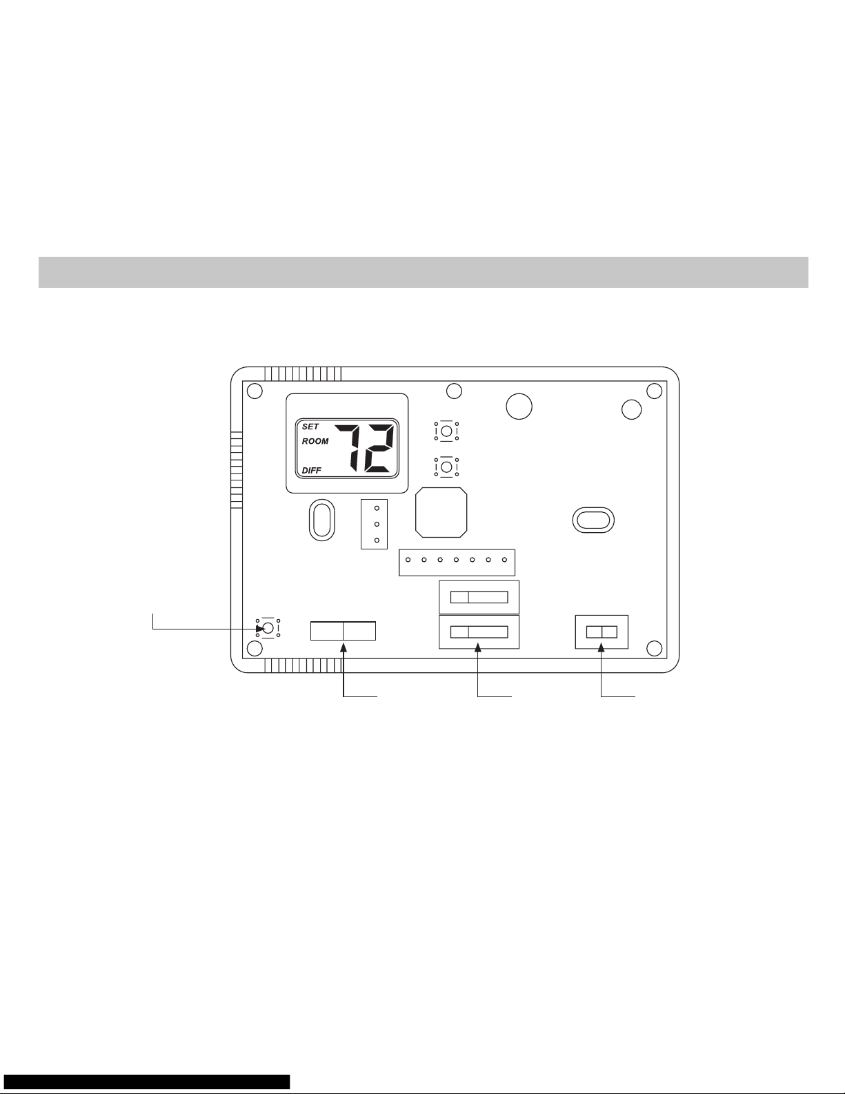
SimpleComfort® 3201 Parts Diagram
Fan Switch
Reset Button
Cool Emer
Off
OnAuto
Heat
Y2Y1EGW2OB
Mode/Hold
Switch
System
Switch
C
L
R
Mode Hold

2
Electrical Rating: • 24 VAC (18-30 VAC) • 1 amp maximum per terminal
• 4 amp maximum total load • 60 minute power loss backup for clock
Temperature control range: 45°F to 90°F (7°C to 32°C) Accuracy: ± 1°F (± 0.5°C)
System configurations: 2-stage heat, 2-stage cool, heat pump
Terminations: C, L, R, B, O, W2, G, E, Y1, Y2
Specications
WARNING!
: Always turn off power at the main power supply before installing, cleaning, or removing
thermostat.
• This thermostat is for 24 VAC applications only; do not use on voltages over 30 VAC
• All wiring must conform to local and national electrical and building codes
• Do not use air conditioning when the outdoor temperature is below 50 degrees; this can damage your
A/C system and cause personal injuries
• Use this thermostat only as described in this manual
Important Safety Information
Package includes: SimpleComfort® 3201 programmable thermostat on base, labeled thermostat cover,
wiring labels, screws and wall anchors, Installation, Operation and Application Guide.
Tools required for installation: Drill with 3/16” bit, hammer, screwdriver.
Package Contents/Tools Required
3
ELECTRICAL SHOCK HAZARD – Turn off power at the main service panel by removing the fuse
or switching the appropriate circuit breaker to the OFF position before removing the existing
thermostat.
1.
Turn off power to the heating and cooling system by removing the fuse or switching the appropriate
circuit breaker off.
2. Remove cover of old thermostat. This should expose the wires.
3. Label the existing wires with the enclosed wire labels before removing wires.
4. After labeling wires, remove wires from wire terminals.
5. Remove existing thermostat base from wall.
6. Refer to the following section for instructions on how to install this thermostat.
To Remove Existing Thermostat
ELECTRICAL SHOCK HAZARD – Turn off power at the main service panel by removing the fuse
or switching the appropriate circuit breaker to the OFF position before removing the existing
thermostat.
IMPORTANT:
Thermostat installation must conform to local and national building and electrical
codes and ordinances.
Note:
Mount the thermostat about five feet above the floor. Do not mount the thermostat on an
outside wall, in direct sunlight, behind a door, or in an area affected by a vent or duct.
1. Turn off power to the heating and cooling system by removing the fuse or switching the appropriate
circuit breaker off. Move the System switch to OFF
.
To Install Thermostat

4
To Install Thermostat (continued)
2. To remove cover, insert and twist a coin or screwdriver in the slots on the sides of the thermostat.
3. Put thermostat base against the wall where you plan to mount it (Be sure wires will feed through the
wire opening in the base of the thermostat).
4. Mark the placement of the mounting holes.
5. Set thermostat base and cover away from working area.
6. Using a 3/16” drill bit, drill holes in the places you have marked for mounting.
7. Use a hammer to tap supplied anchors in mounting holes.
8. Align thermostat base with mounting holes and feed the control wires through the wire opening.
9. Use supplied screws to mount thermostat base to wall.
10. Insert stripped, labeled wires in matching wire terminals. See “Wiring Diagrams” section of this
manual (Pages 5-16).
CAUTION!
:
Be sure exposed portion of wires does not touch other wires.
11. Tighten screws on terminal block. Gently tug wire to be sure of proper connection. Double check that
each wire is connected to the proper terminal.
12. Seal hole for wires behind thermostat with non-flammable insulation or putty.
13. Replace cover on thermostat by snapping it in place.
14. Turn on power to the system at the main service panel.
15. Test thermostat operation as described in “Testing the Thermostat” (Page 20).
5
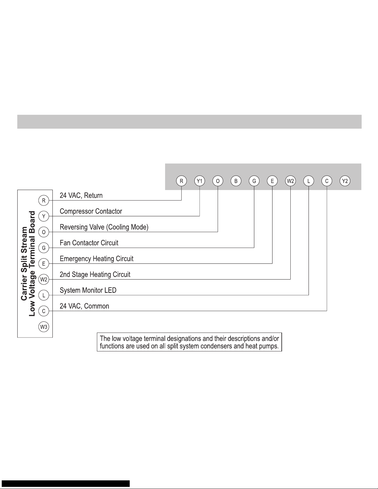
Wiring Diagrams
SimpleComfort® 3201 Electronic Thermostat Conversion to:
Carrier Split Stream Condensers and Heat Pump Systems
SC 3201 Electronic Thermostat
6
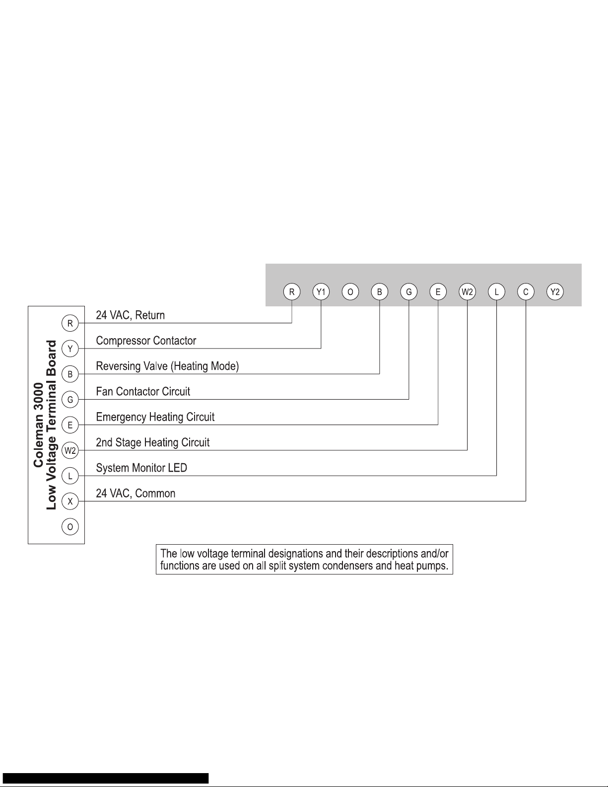
SimpleComfort® 3201 Electronic Thermostat Conversion to:
Coleman 3000 Series Heat Pump Systems
SC 3201 Electronic Thermostat
7
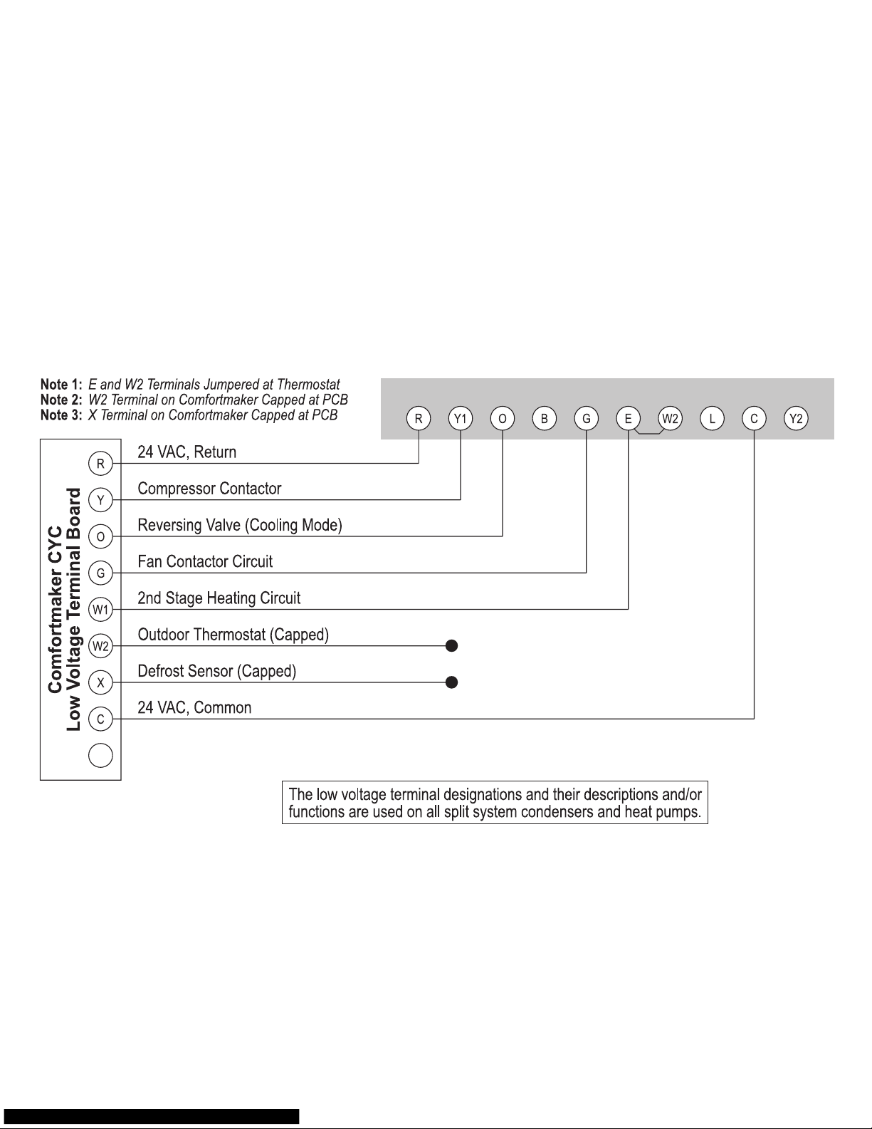
SimpleComfort® 3201 Electronic Thermostat Conversion to:
Comfortmaker CYC Series Heat Pump Systems
SC 3201 Electronic Thermostat
(capped)
(capped)
8
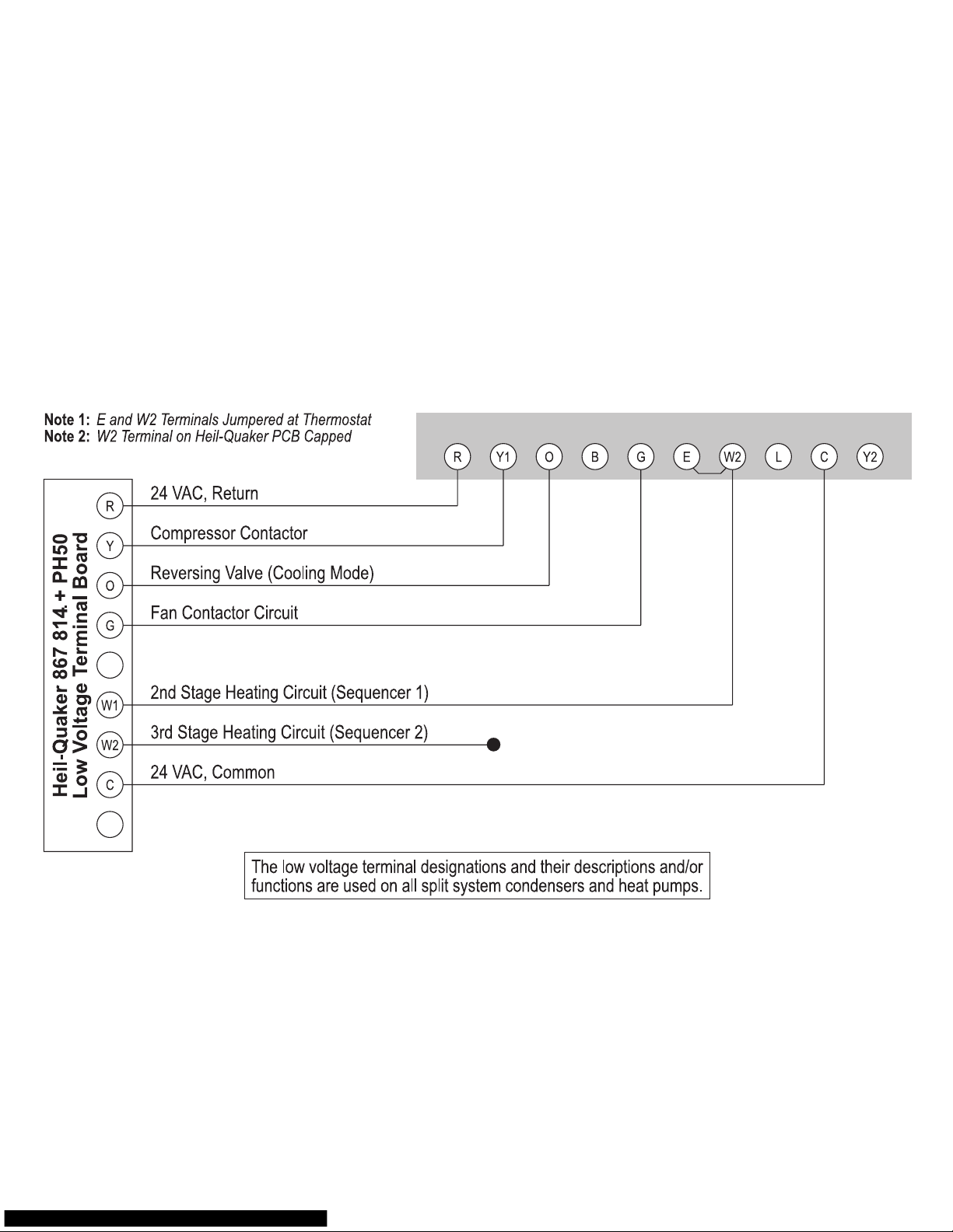
SimpleComfort® 3201 Electronic Thermostat Conversion to:
Heil-Quaker 867.814 Series and PH50 Series Heat Pump Systems
SC 3201 Electronic Thermostat
(capped)
 Loading...