

Page 1
Auto Changeover
7-Day Programmable
Hardwired
SC 3006
Programmable Electronic Thermostat
Installation, Operation & Application Guide
For more information on our complete range of American-made
products – plus wiring diagrams, troubleshooting tips and more,
visit us at www.icmcontrols.com
• 7-Day Programmable
•
Single Stage Heat Pump/Non-Heat Pump Systems
• Backlit Display
•
Single Stage Heat/Cool Systems
•
Field Calibration
•
Auto Changeover
•
Button Lockout Function
•
Compatible with Gas, Oil, or Electric
• Simpleset® Programming
• Remote Temperature Sensor Capability
• Title 24 Compliant / No Batteries Required
• Relay Outputs
(minimum voltage drop in thermostat)
• Ideally Suited for:
–
Residential (New Construction/Replacement),
Light Commercial
Page 2

Table of Contents
Specifications ........................................................................................................................1
Important Safety Information ...............................................................................................1
Package Contents/Tools Required .........................................................................................1
To Remove Existing Thermostat ..........................................................................................2
To Install Thermostat ............................................................................................................ 2
Remote Sensor Installation (Optional) .................................................................................. 4
Wiring Diagrams ....................................................................................................................5
Configuration Mode ...............................................................................................................8
Starting the Thermostat .....................................................................................................10
Testing the Thermostat ...................................................................................................... 11
Mode of Operation ..............................................................................................................12
Operating Modes ................................................................................................................13
Setting the Time and Day of the Week ............................................................................... 14
Programming ...................................................................................................................... 15
Simpleset® Programming ....................................................................................................17
Lockout Function ................................................................................................................17
Factory Preprogramming .................................................................................................... 18
Personal Program Schedule ................................................................................................18
Troubleshooting ..................................................................................................................20
Page 3

1
Electrical Rating: • 24 VAC (18 to 30 VAC) • 1 amp maximum per terminal
• 3 amp maximum total load
Temperature control ranges: 45°F to 90°F Accuracy: ± 1°F
System configurations: 1-stage heat, 1-stage cool, heat pump, gas, oil, electric
Timing: Anti-short Cycle: 5 minutes
Backlight Operation: 10 seconds
Terminations: C, RH, RC, W, Y, B, O, G, S1, S2
Specications
WARNING!
: Always turn off power at the main power supply before installing, cleaning, or removing
thermostat.
• This thermostat is for 24 VAC applications only; do not use on voltages over 30 VAC
• Do not short across terminals of gas valve or system control to test operation; this will damage your
thermostat and void your warranty
• All wiring must conform to local and national electrical and building codes
• Do not use air conditioning when the outdoor temperature is below 50 degrees; this can damage your
A/C system and cause personal injuries
• Use this thermostat only as described in this manual
Important Safety Information
Package includes: SimpleComfort® 3006 programmable thermostat on base, labeled thermostat cover,
wiring labels, screws and wall anchors, Installation, Operation and Application Guide.
Tools required for installation: drill, hammer, screwdriver.
Package Contents/Tools Required
Page 4

2
To Remove Existing Thermostat
ELECTRICAL SHOCK HAZARD – Turn off power at the main service panel by removing the fuse
or switching the appropriate circuit breaker to the OFF position before removing the existing
thermostat.
1. Turn off power to the heating and cooling system by removing the fuse or switching the appropriate
circuit breaker off.
2. Remove cover of old thermostat. This should expose the wires.
3. Label the existing wires with the enclosed wire labels before removing wires.
4. After labeling wires, remove wires from wire terminals.
5. Remove existing thermostat base from wall.
6. Refer to the following section for instructions on how to install this thermostat.
To Install Thermostat
ELECTRICAL SHOCK HAZARD – Turn off power at the main service panel by removing the fuse
or switching the appropriate circuit breaker to the OFF position before removing the existing
thermostat.
IMPORTANT: Thermostat installation must conform to local and national building and electrical
codes and ordinances.
Note:
Mount the thermostat about five feet above the floor. Do not mount the thermostat on an
outside wall, in direct sunlight, behind a door, or in an area affected by a vent or duct.
1. Turn off power to the heating and cooling system by removing the fuse or switching the appropriate
circuit breaker off.
Page 5

3
To Install Thermostat (continued)
2. To remove cover, insert and twist a coin or screwdriver in the slots on the sides of the thermostat.
3. Put thermostat base against the wall where you plan to mount it (Be sure wires will feed through the
wire opening in the base of the thermostat).
4. Mark the placement of the mounting holes.
5. Set thermostat base and cover away from working area.
6. Using a 3/16” drill bit, drill holes in the places you have marked for mounting.
7. Use a hammer to tap supplied anchors in mounting holes.
8. Align thermostat base with mounting holes and feed the control wires through wire opening.
9. Use supplied screws to mount thermostat base to wall.
10. Insert stripped, labeled wires in matching wire terminals. See “Wiring Diagrams” section of this
manual (Page 5).
CAUTION!
:
Be sure exposed portion of wires does not touch other wires.
11. Tighten screws on terminal block. Gently tug wire to be sure of proper connection. Double check that
each wire is connected to the proper terminal.
12. Seal hole for wires behind thermostat with non-flammable insulation or putty.
13. Set Gas/Electric switch. Set to gas for oil or gas systems. Set to electric for heat pumps or electric
heat systems.
14. Replace cover on thermostat by snapping it in place.
15. Turn on power to the system at the main service panel.
16. Test thermostat operation as described in “Testing the Thermostat” (Page 11).
Page 6
4
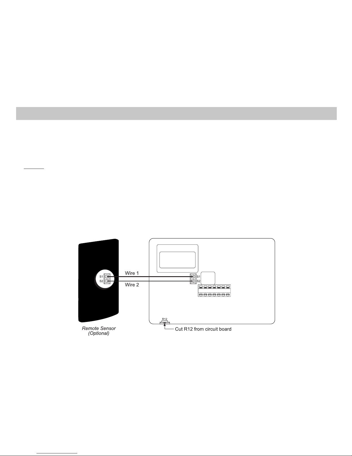
1. Remove cover from remote sensor housing.
2. Select an appropriate location for mounting the remote sensor.
3. Mount remote sensor unit using hardware provided.
4. Install two strand shielded wire between remote sensor and thermostat. Shielded wire must be used.
Do not run remote sensor wire in conduit with other wires.
• Wire 1 should run between the S1 terminal on the thermostat and the S1 terminal on the
remote sensor
• Wire 2 should run between the S2 terminal on the thermostat and the S2 terminal on the
remote sensor
• Connect the shielding of the wire to the S2 terminal on the thermostat
5. Disable the main sensor (R12) on the thermostat by cutting it from the circuit board.
Remote Sensor Installation (Optional)
Page 7

5
Wiring Diagrams
Fan
Control
4 or 5 Wire,
Fan
Control
Page 8

6
Page 9

7
Page 10

8
The configuration mode is used to set the SC3006 to match your heating/cooling system. The SC3006 functions
with heat pump, air conditioning, gas, oil or electric heat systems.
1. To enter the configuration mode, simultaneously hold down the and buttons while the SC3006 is in OFF mode.
2. Press the or button to change settings within each screen.
3. Press the button to advance to the next screen.
Note: The button will return you to the previous screen.
4. To exit configuration mode, hold the button for 6 seconds.
Configuration Mode Settings
The setup screens for configuration mode are as follows:
1. Temperature scale (F or C) – Choose Fahrenheit or Celsius.
Press the or button to select.
Press the button to advance to the next screen.
2. Differential (1°F - 5°F) (1°C - 3°C) – Set the number of degrees between your “turn on”
temperature and your “setpoint” temperature.
Press the or button to set differential value.
Press the button to advance to the next screen.
3. Deadband (1°F - 9°F) (1°C - 5°C) – Set the minimum number of degrees between your heating
system activation and your cooling system activation.
Press the or button to set deadband value.
Press the button to advance to the next screen.
Conguration Mode
Page 11

9
4. Heat pump – Press the or button to configure as heat pump, or
non-heat pump system.
• ON = Heat pump system – 4 minute time delay with heat and cool
• OFF = Non-heat pump system – 4 minute time delay with cool only
Press the button to advance to the next screen.
Configuration Mode Settings (continued)
5. Lockout (0-8°, NITE, COOL-HEAT) – Select the number of degrees set
temperature can be changed during keypad lockout or select to lockout during
NITE period only. COOL-HEAT lockout allows adjustment of the set temperatures
to the maximum heat set temperature selected in Step 6 and minimum cool set
temperature selected in Step 7.
Note: The mode cannot be changed when the thermostat is locked.
Press the or button to select.
Press the button to advance to the next screen.
6. Maximum Heat Setpoint (45°F - 90°F) (7°C - 32°C)
Adjust to control the maximum heat set temperature allowed.
Press the or button to select.
Press the button to advance to the next screen
7. Minimum Cool Setpoint (45°F - 90°F) (7°C - 32°C)
Adjust to control the minimum cool set temperature allowed.
Press the or button to select.
Press the button to advance to the next screen.
Page 12

10
CAUTION!
:
Do not use air conditioning when the outdoor temperature is below 50 degrees. This
can damage your air conditioning system and cause personal injuries.
Note:
First button press activates backlight only.
1. Move the Fan Auto/On switch to the Auto position.
2. Press the button to enter desired operating mode.
Mode
8. Room temperature offset (+9°F to - 9°F) (+5°C to -5°C).
Adjust to calibrate displayed room temperature to match actual room temperature.
Press the button to advance to the next screen.
9. Maximum compressor cycles allowed per hour (d, 2-6).
– – = as many as needed, 2-6 = maximum cycles/hour
Press the button to advance to the next screen.
Configuration Mode Settings (continued)
ON
10. Status indicator light (ON, OFF).
Press the or button to select.
To exit configuration mode, press the button for 6 seconds.
Starting the Thermostat
Fan
Page 13

11
Testing the Thermostat
Once the thermostat is installed, it should be thoroughly tested.
CAUTION!
:
Do not energize the air conditioning system when the outdoor temperature is below
50 degrees. It can result in equipment damage or personal injury.
Cool Test
1. Press mode button until cool mode is displayed.
2. Adjust set temperature so it is 5 degrees below room temperature.
3. Air conditioning should come on. Green LED turns ON.
4. Adjust the set temperature 2 degrees above the room temperature and the
A/C should turn off. There may be a fan delay on your system.
Note:
There is a four-minute time delay to protect the compressor after it
turns off.
Heat Test
1. Press mode button until heat mode is displayed.
2. Adjust the set temperature so it is 5 degrees above the room
temperature.
3. Heat should come on. Red LED turns ON.
4. Adjust the set temperature 2 degrees below the room temperature and
the heat should turn off. There may be a fan delay on your system.
Note:
For heat pumps, there is a four-minute delay to protect your compressor.
Fan Test
1. Slide fan switch to ON position. Indoor fan turns ON.
2. Slide fan switch to Auto position. Indoor fan turns OFF.
Page 14

12
The SC3006 is a programmable, auto changeover, single stage heat, single stage cool thermostat. It
functions with air conditioning, heat pumps, gas, oil or electric heat systems.
The thermostat activates the heating appliance when the room temperature is below the set heat
temperature (by the differential temperature) and the red indicator light on the thermostat will light. The
SC3006 will stop outputting and the red light will turn off when the call for heat has been satisfied. With
heat pumps, the thermostat will not let the compressor come on for 4 minutes after it turns off. This
protects your compressor.
When the room temperature is greater than the set cool temperature (by the differential temperature),
the cooling device is activated and the green indicator light on the thermostat will turn on. The SC3006 will
stop outputting and the green light will turn off when the call for cooling is satisfied. The thermostat will
not let the compressor come on for 4 minutes after it turns off. This protects your compressor.
The SC3006 has five possible operating modes: OFF, Heat, Cool, Heat & Cool and Program mode. In off
mode, the thermostat will not turn on heating or cooling devices. The manual fan can be turned on in all
operating modes using the fan switch. In heat mode, the thermostat controls the heating system. In the
Cool mode, the thermostat controls the cooling system. In heat & cool mode, the thermostat controls
both the heating and cooling systems. In program mode, the thermostat will automatically be controlled by
the set program. Program mode can function with heat mode, cool mode or heat & cool mode. The clock
display alternates with the set temperature display for heat & cool mode.
The program schedule can be overridden by changing the set temperature ( or button). This puts the
SC3006 thermostat into a 2 hour temporary hold. After 2 hours, it will automatically return to the program
schedule.
The SC3006 also has a button lockout feature. This enables the thermostat to be set to the proper mode
and temperature and locked so it cannot be tampered with.
Mode of Operation
Page 15

13
Operating Modes
There are five possible operating modes for the SC3006. Off, Cool, Heat, and Cool & Heat modes are
accessed by pressing the Mode button. Program mode is accessed by pressing the Prog button.
OFF Mode
• In this mode, the thermostat will not turn on the heating or cooling devices
Note: The indoor fan can be turned on manually in every operating mode by
sliding the auto/on switch to ON.
Cool Mode
• In this mode, the thermostat controls the cooling system
Note: There is a four minute delay for your compressor to restart after it has
turned off.
Heat Mode
• In this mode, the thermostat controls the heating system
Note: For heat pumps, there is a four minute delay for your compressor to
restart after it has turned off.
Program Mode
• In this mode, the program function is on (PROG displays), and the thermostat
will automatically be controlled by the set program schedule. Program mode can
function with heat mode, cool mode or heat & cool mode. The program schedule
can be overridden by changing the set temperature ( or button). After 2
hours, the program schedule will automatically be resumed. To manually
return to the program schedule, press the button twice.
Cool and Heat Mode (Auto Changeover)
• In this mode, the thermostat controls the cooling and heating systems,
automatically changing over from one to the other as needed
Page 16

14
The time and day of the week must be set for your program schedule to operate correctly.
1. Press the button until you are in the OFF mode.
2. Press the button in for 6 seconds. Time displays.
3. Press the or button to adjust the time.
4. Press the button while the time is displayed. The display shows the day
currently set on the thermostat (1=Monday, 2=Tuesday, etc).
5. Press the or button to set the correct day of the week that today is.
Note: Press the button in for 5 seconds to lock values into memory and return
to the OFF mode or press the button once to enter programming.
Setting the Time and Day of the Week
Page 17

15
Program Overview
The SC3006 programmable thermostat has four periods (MORN, DAY, EVE, NITE) that are customizable
for each day of the week. Each period will have a start time, heat temperature, and cool temperature. The
SC3006 monitors the day and time, while maintaining the specific conditions you have chosen for each
period in your program.
1. Press the button until you are in the OFF mode.
2. Press the button for 6 seconds.
3. Press the button twice.
• Day is displayed (1-7)
4. Press the or button to change the day you want to program
(1=Monday, 2=Tuesday, etc.).
5. Press the button to advance to the next screen.
Note: You can always press the button to return to the
previous parameter.
• Period is displayed (MORN, DAY, EVE, NITE)
6. Press the or button to change period of day.
7. Press the button to advance to the next screen.
Programming
Page 18

16
Programming (continued)
• Set time is displayed
8. Press the or button to change set time.
9. Press the button to advance to the next screen.
Note: Transitions required af ter 11:59 PM must be programmed in the
next day’s MORN transition.
• Heat temperature is displayed (45°F to 90°F)
10. Press the or button to adjust heat set temperature.
11. Press the button to advance to the next screen.
• Cool temperature is displayed (45°F to 90°F)
Note: Cool cannot be set lower than heat temperature.
12. Press the or button to adjust cool set temperature.
13. Press the button to advance to the next screen.
Repeat steps 1-13 to program each day of the week individually or use the
Simpleset® feature (see Page 17) to program every day the same as Monday.
When programming is complete, press and hold the button in for 5 seconds to return to the OFF mode.
PROG must display on the screen for the thermostat to follow the program schedule. If PROG does not
appear, press the PROG button until PROG displays.
Page 19

17
Simpleset® Programming
Simpleset® programming is a convenient method of programming the thermostat. Once the entire Monday
(Day 1) schedule is set, Simpleset® programming will copy the Monday schedule to every day of the week.
After the complete Monday schedule is set (see Programming on Page 14), you are at the Day 2 screen:
1. Press the button once. Day 1 screen displays.
2. Press and hold the button for 3 seconds.
• The days of the week will count down from 7 to 1 and this will lock the
settings into memory.
• Once the schedule is locked in, you can go through each day and make
any changes you require. This feature speeds up the programming of
the standard weekday/weekend schedule.
3. Press and hold the button for 5 seconds to exit program mode and return to the OFF mode.
The SC3006 thermostat has a button lockout feature so the settings cannot be changed or tampered
with. With the lockout activated, any button press will result in “LOC” being displayed.
To activate the LOC function:
1. Press the button and hold it in.
2. Also press the button and keep both depressed for 10 seconds.
3. LOC will display and all buttons will be disabled.
To deactivate the LOC feature, repeat steps 1 & 2 above.
Lockout Function
Page 20

18
Factory Preprogramming
Use the following personal program schedule to record your settings:
MORN DAY EVE NITE
HEAT HEAT HEAT HEAT
COOL COOL COOL COOL
MONDAY
1
MORN DAY EVE NITE
HEAT HEAT HEAT HEAT
COOL COOL COOL COOL
TUESDAY
2
MORN DAY EVE NITE
HEAT HEAT HEAT HEAT
COOL COOL COOL COOL
WEDNESDAY
3
The SC3006 comes preprogrammed with the following schedule:
MORN 6:00 AM DAY 8:00 AM EVE 6:00 PM NITE 10:00 PM
HEAT 70°F HEAT 62°F HEAT 70°F HEAT 62°F
COOL 78°F COOL 85°F COOL 78°F COOL 82°F
MONDAY
thru
SUNDAY
Personal Program Schedule
Page 21

19
Personal Program Schedule (continued)
MORN DAY EVE NITE
HEAT HEAT HEAT HEAT
COOL COOL COOL COOL
THURSDAY
4
MORN DAY EVE NITE
HEAT HEAT HEAT HEAT
COOL COOL COOL COOL
FRIDAY
5
MORN DAY EVE NITE
HEAT HEAT HEAT HEAT
COOL COOL COOL COOL
SATURDAY
6
MORN DAY EVE NITE
HEAT HEAT HEAT HEAT
COOL COOL COOL COOL
SUNDAY
7
Page 22

20
Symptom Remedy
No display Check for 24 VAC at thermostat; display is blank when 24 VAC is not present
System fan does not come on properly Verify wiring is correct, check Gas/Electric switch position
All thermostat buttons are inoperative Verify 24 VAC is present; unit locks out when 24 VAC is not present
No response with first button press First button press activates backlight only
Program schedule activates at the wrong
time
Check time (AM/PM) set on thermostat (see “Setting the Time,” Page 14)
Thermostat turns on and off too frequently Adjust temperature differential (see “Configuration Mode Setting 2,” Page 8)
Thermostat does not follow program Verify it is operating in program mode (PROG displays); check time (AM/PM);
check if in 2 hour program override
Fan runs continuously Check Fan On/Auto switch, fan runs continuously in On position
Status indicator light not on during call Turn status indicator function on
(see “Configuration Mode Setting 10,” Page 10)
Room temperature is not correct Verify wall hole for wires is plugged with putty or insulation, calibrate thermostat
(see “Configuration Mode Setting 8,” Page 10).
If remote sensor is used, check S1 and S2 terminal connections
LOC displays when any button is pressed Thermostat has the button lockout function activated (see “Lockout Function,”
Page 17)
– – on display instead of room temperature Check for a bad connection at S1 and S2 terminals, if used
Problem not listed above Press Reset button once*
* Reset Button Function
Time, day and mode changed to last saved settings (saved after power loss or when exiting
program setup), configuration and program settings are unchanged.
Troubleshooting
Page 23

ONE-YEAR LIMITED WARRANTY
The Seller warrants its products against defects in material or workmanship for a period of one
(1) year from the date of manufacture. The liability of the Seller is limited, at its option, to repair,
replace or issue a non-case credit for the purchase prices of the goods which are provided to
be defective. The warranty and remedies set forth herein do not apply to any goods or parts
thereof which have been subjected to misuse including any use or application in violation of the
Seller’s instructions, neglect, tampering, improper storage, incorrect installation or servicing
not performed by the Seller. In order to permit the Seller to properly administer the warranty,
the Buyer shall: 1) Notify the Seller promptly of any claim, submitting date code information or
any other pertinent data as requested by the Seller. 2) Permit the Seller to inspect and test the
product claimed to be defective. Items claimed to be defective and are determined by Seller
to be non-defective are subject to a $30.00 per hour inspection fee. This warranty constitutes
the Seller’s sole liability hereunder and is in lieu of any other warranty expressed, implied or
statutory. Unless otherwise stated in writing, Seller makes no warranty that the goods depicted
or described herein are fit for any particular purpose.
LIA160-6
Patent No. 424,953
7313 William Barry Blvd., North Syracuse, NY 13212
(Toll Free) 800-365-5525 (Phone) 315-233-5266 (Fax) 315-233-5276
www.icmcontrols.com
 Loading...