

ICM Controls SimpleComfort 2010, SC 2010 Installation, Operation & Application Manual


Manual Changeover
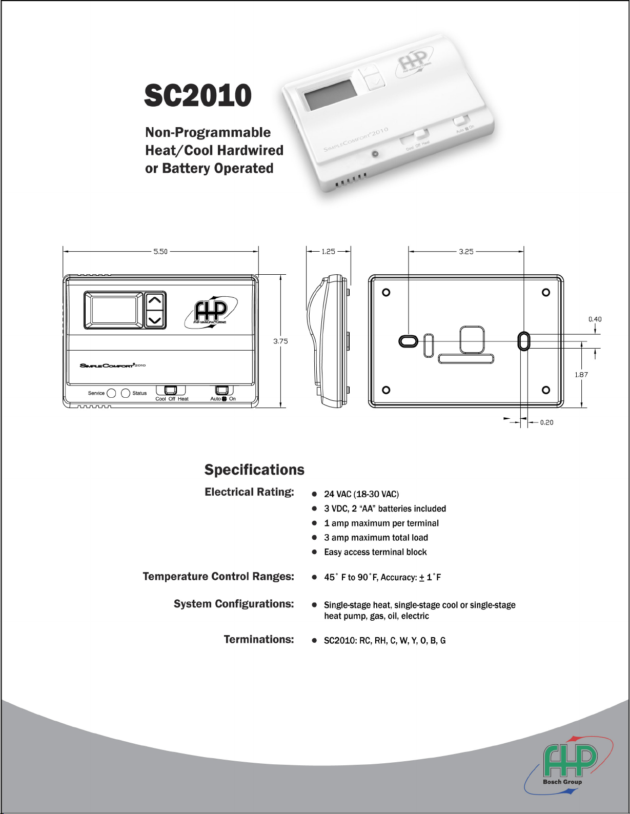
SC 2010
Battery or Hardwire
Non-Programmable Electronic Thermostat
• Configurable
• Single Stage Heat/Cool Systems
• Single Stage Heat Pump Systems
• Backlit Display
• Compatible with Gas, Oil, or Electric
• Filter Check
• Status Indicator Light
• Relay Outputs
(minimum voltage drop in thermostat)
• Ideally Suited for:
–
Residential (New Construction/Replacement)
–
Light Commercial
Installation, Operation & Application Guide
For more information on our complete range of American-made
products – plus wiring diagrams, troubleshooting tips and more,
visit us at www.icmcontrols.com
1 Heat/1 Cool

Table of Contents
Parts Diagram .............................................................................................................................1
Specifications ..............................................................................................................................2
Important Safety Information .....................................................................................................2
Package Contents/Tools Required ...............................................................................................2
To Remove Existing Thermostat ................................................................................................ 3
To Install Thermostat .................................................................................................................. 3
Wiring Diagrams .......................................................................................................................... 5
Configuration Mode ................................................................................................................... 10
Testing the Thermostat ............................................................................................................13
Mode of Operation .................................................................................................................... 14
Troubleshooting ........................................................................................................................15
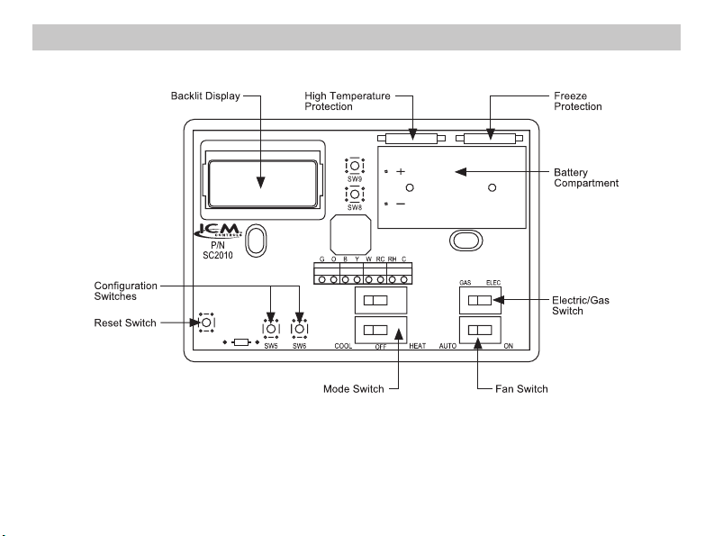
Parts Diagram
1

Specications
Electrical rating: • 24 VAC (18-30 VAC) • DC Power: 3.0 VDC (2 “AA” batteries included)
• 1 amp maximum per terminal • 3 amp maximum total load
Temperature control range: 45°F to 90°F (7°C to 32°C) Accuracy : ± 1°F (± 0.5°C)
System configurations: 1-stage heat, 1-stage cool, heat pump, gas, oil, electric
Timing:
Anti-short Cycle:
Backlight Operation: Battery for 5 seconds, hardwired for 10 seconds
Terminations: RC, RH, W, Y, B, O, G, C
5 minutes
Important Safety Information
WARNING!
• This thermostat is for 24 VAC applications only; do not use on voltages over 30 VAC
• Do not short across terminals of gas valve or system control to test operation; this will damage your
thermostat and void your warranty
• All wiring must conform to local and national electrical and building codes
• Do not use air conditioning when the outdoor temperature is below 50 degrees; this can damage your
A/C system and cause personal injuries
• Use this thermostat only as described in this manual
:
Always turn off power at the main power supply before installing, cleaning, or removing
thermostat.
Package Contents/Tools Required
Package includes: SimpleComfort® 2010 thermostat on base, thermostat cover, wiring labels, screws and
Tools required for installation: Drill with 3/16” bit, hammer, screwdriver
2
wall anchors, Installation, Operation and Application Guide
To Remove Existing Thermostat
ELECTRICAL SHOCK HAZARD
or switching the appropriate circuit breaker to the OFF position before removing the existing
thermostat.
1. Turn off power to the heating and cooling system by removing the fuse or switching the appropriate
circuit breaker off.
2. Remove cover of old thermostat. This should expose the wires.
3. Label the existing wires with the enclosed wire labels before removing wires.
4. After labeling wires, remove wires from wire terminals.
5. Remove existing thermostat base from wall.
6. Refer to the following section for instructions on how to install this thermostat.
– Turn off power at the main service panel by removing the fuse
To Install Thermostat
ELECTRICAL SHOCK HAZARD
or switching the appropriate circuit breaker to the OFF position before removing the existing
thermostat.
IMPORTANT: Thermostat installation must conform to local and national building and electrical
codes and ordinances.
Note: Mount the thermostat about five feet above the floor. Do not mount the thermostat on an
outside wall, in direct sunlight, behind a door, or in an area affected by a vent or duct.
1. Turn off power to the heating and cooling system by removing the fuse or switching the appropriate
circuit breaker off.
– Turn off power at the main service panel by removing the fuse
3
 Loading...