

Icm controls ICM491 User Manual
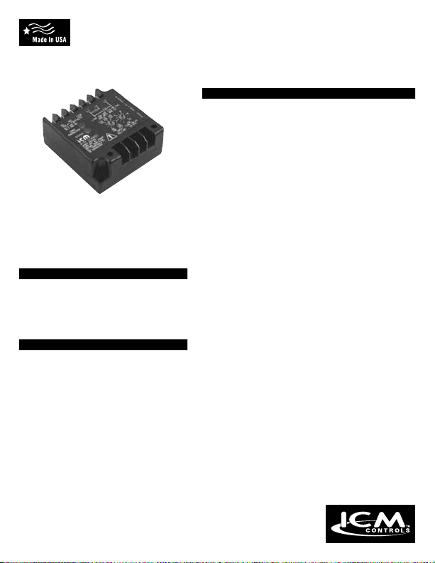
ICM491
Single Phase Line Monitor
Reliable line voltage protection for single phase systems
SPECIFICATIONS
Input
• Line Voltage: 95-135 VAC or 190-270 VAC
(selectable)
• Maximum Operating Input: 142-275 VAC
• Line Frequency: 50-60 Hz
Output
• Type: Relay, energized upon acceptable
conditions
• Form: SPDT, Single Pole, Double Throw
• Ratings: 6A @ 120 VAC resistive
Protects against High/Low
voltage and rapid system
recycling, 95-270 VAC
operation, adjustable
anti-short cycle timer...
DESCRIPTION
The ICM491 was specically designed
to guard equipment against damage
caused by under/over voltage conditions
and/or rapid system recycling.
FEATURES
• 5-Second Interrogation Delay... helps
prevent nuisance tripping
• LED Indication... normal run and fault
indications
• 95-270 VAC Operation... in a single
model
• Integral Anti-Short Cycle
Protection... “Delay on break” circuit
provides adjustable (.1 to 10 minutes)
lockout delay to prevent rapid system
recycling; no external ASC timers
required
• Meets IEEE 587... A&B for transient
protection
7313 William Barry Blvd., North Syracuse, NY 13212
(Phone) 315-233-5266 (Toll Free) 800-365-5525
LII114-1
(Fax) 315-233-5276
www.icmcontrols.com
5A @ 240 VAC resistive
Response Times
• Line Dropout: .05 seconds (typical)
• Line Voltage Sag: 5 seconds (typical)
• Turn On (sec): Based on minimum time
selected
Lockout Delay Timer
• Dry Relay Contacts
• Time Delay: Adjusts from 6-600 seconds
(+/- 10%)
Under Voltage Protection
• Voltage Dropout: Setpoint is -12%
• Voltage Pickup: Setpoint is -8%
Over Voltage Protection
• Voltage Dropout: Setpoint +12%
• Voltage Pickup: Setpoint +8%
Environmental
• Operating Temperature: -40°F to +167°F
(-40°C to +75°C)
• Transient Protection: Meets IEEE 587
Standards for Categories A&B without false output
or degradation
– (6Kv 0.5 µs x 100 KHz Ring Wave)
– (6Kv 1.2 x 50 µs Impulse Wave)
Mechanical
• Mounting: Surface mount using (2) #8 screws
• Terminations: .25” male quick-connect
terminals
MODE OF OPERATION
Upon application of power to the monitor, and provided all voltages and line conditions are acceptable,
the green load energized LED indicator will glow. This is an indication that the output contacts have
successfully transferred.
Should a High/Low voltage condition exist for longer than the 5 second interrogation delay or a loss of
power for more than 50 mS, the relay and green LED shall be de-energized. The red status LED will
rapidly ash. Re-energization is automatic upon correction of the fault condition, after the anti-short
cycle time delay is complete. Should a fault condition exist upon application of power, the relay will not
energize and the red status LED will ash rapidly, indicating power is outside specications. A blinking
LED indicates power is good, but unit is still in ASC lockout.
Adjustment: Select the desired operating voltage. If status LED blinks once per second, voltage is within
specication and unit is awaiting the end of the ASC delay. If the red status LED rapidly ashes red,
adjusting input voltage knob higher or lower should cause a slow blink to result, but ensure input voltage
is not beyond motor operating specication. Once input voltage is properly set, adjust “ASC Time Delay”
knob to desired ASC delay.
INSTALLATION
1. Determine operating voltage,
95-135 VAC or 190-270 VAC.
2. Disconnect power.
3. Connect the ICM491’s power connections
(L1 & L2) to power supply lines L1 & L2 (or
N). Ensure there is only one “L2” terminal
connected at any time:
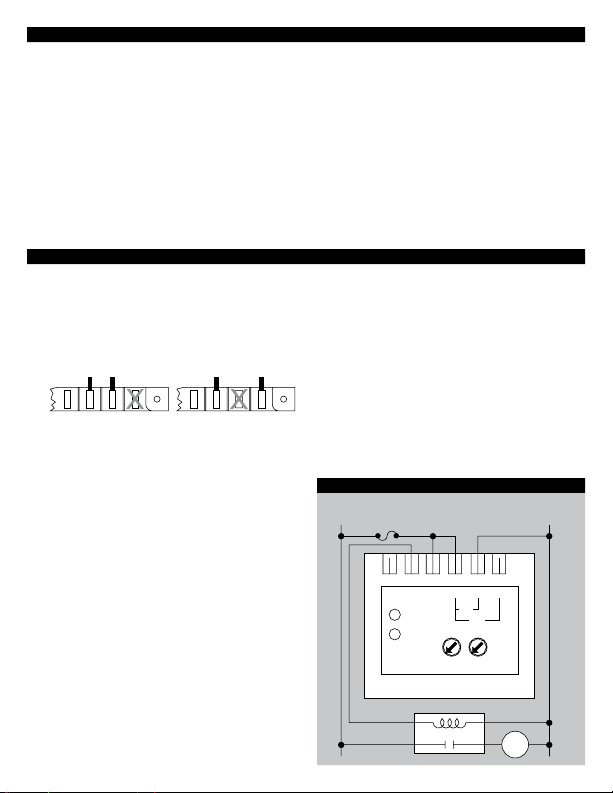
OM L1 L2 L2 OM L1 L2 L2
For
95-135 VAC Operation
4. Find a convenient location in control circuit
where the ICM491’s on-board relay contacts
can make or break the control circuit. The
“COM” terminal connects to the “NO” contact
when power is within specication, “COM”
connects to “NC” when power is outside
specication.
5a. With control power off, cut control circuit and
terminate control wires with 1/4” female spade
connections. Connect one terminated line to
“COM” terminal, the other terminated line to
“NO” terminal.
5b. For new installations, where the control circuit
voltage is the same as the voltage being
monitored, it may be easier to connect “COM”
terminal to “L1” terminal with a jumper wire
as shown in ladder diagram. Then, connect
control circuit to terminal “NO.”
6. Set the “input voltage” knob to the actual line
voltage, or to the motor’s nameplate voltage.
7. Turn the “ASC Time Delay” knob to its
minimum position (counter-clockwise).
For
190-270 VAC Operation
8. Apply power. Observe “Load Energized” and
“Status” LEDs. If incoming power is within
specication, unit will energize load in 6
seconds. The following is a table showing what
LED indicators correspond to:
LED STATE INDICATION
Load Energized Off Internal relay is de-energized
Load Energized On Internal relay is energized
Status Off Voltage is within range
Status Blink Voltage is good, unit is in ASC
Status Rapid Flash Voltage is out of range
Note: Both LEDs off indicates no power to
unit.
9. Set the “ASC Time Delay” to the desired antishort cycle lockout time.
WIRING DIAGRAM
Typical wiring diagram for 115 VAC system
L1 L2/NFuse
NC COMNO L1 L2 L2
ICM491
115
230
115 VAC Contactor
Motor
 Loading...