

ICM CONTROLS ICM280 Installation Manual
ICM
GOODMAN REPLACEMENT BOARD
REPLACEMENT of B18099-06, B18099-08 and B18099-10 HSI Module with an ICM280 Board
NOTE: DISCONNECT ALL ELECTRICAL POWER AND SHUT OFF GAS TO THE FURNACE BEFORE PROCEEDING
CAUTION! Label all wires prior to disconnection when servicing controls. Wiring errors can cause improper and dangerous operation.
Verify proper operation after servicing.
• Remove both access panels.
• Cut the white jumper wire between pins 1 and 4 of the 9-pin connector for
GMP and GMPV series units
• Do not cut the white jumper wire for GMPN and GMN series units.
• Remove the edgecard connector and other wires from the existing module
and discard the thermostat wires removed from the board (R, W, and G).
• Remove existing HSI module. Note: Do not damage the nylon standoffs.
• Install the ICM280.
• Reconnect the edgecard connector ensuring good contact.
• Push the 9-pin connector into the ICM280. Note: It can only go one way. Do
not force it.
• Reconnect the supplied thermostat wires.
REPLACEMENT of B18099-13 HSI Module with an ICM280 Board
NOTE: For GMT, GDT, GMTH and GMNT units, disregard the 9-pin connector supplied with the ICM280.
• Remove both access panels.
• Locate the red, white and green thermostat wires (pigtails) where they pass
through the side of the furnance cabinet. Remove and save the wire nuts
and then disconnect the pigtails from the main thermostat wire assembly.
• Disconnect all wires from the HSI module
• Discard the thermostat wires (pigtails) removed from the board (terminals R,
W, and G).
• Remove the existing HSI module from the control panel. Do not damage the
nylon standoffs.
• Carefully remove the standoffs and insert them into the same locations on
the ICM280.
• Install the ICM280.
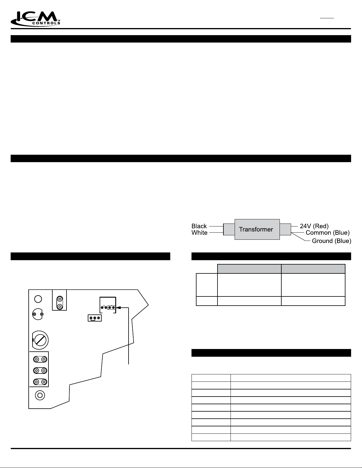
• Remove the red wire from the 24-volt side of the transformer’s secondary
side. Discard it.
• Remove the blue ground wire from the transformer, but do not discard it.
• Remove the blue wire from the transformer. Discard it.
• Place the red wire from the 9-pin connector onto 24-volt (hot) of the
secondary side of the transformer.
• Place the blue wire from the 9-pin connector onto common terminal of the
secondary side of the transformer. This wire has a piggy back terminal.
• Place the blue ground wire, which was previously removed, onto the
common terminal of the transformer.
• Replace both access panel.
• Restore gas and electrical power to the furnace.
• Verify the sequence of operation.
• Reconnect the 9-pin connector into the ICM280. Note: It can only go
one way. Do not force it.
• Route the red, white and green thermostat wires (pigtails) supplied
with the ICM280 through the side of the cabinet and then, using the
wire nuts saved earlier, reconnect them to the main thermostat wire.
• Reconnect all other wires to the controls module being careful to
match the wire labels to the thermostat connections.
28 0
Selecting the Blower Off Delay
In the heating mode, the blower off delay can be used to obtain a 90, 120,
or 150 second period by changing the position of the plastic jumper on the
ignition control. See drawing below for location of this jumper
TWIN
150
90
120
HEAT
STATUS
24V HUM
W
G
R
The control is factory set to give a 150
second blower off delay.
TEST
DELAY
Blower Time O
Jumper
Timing Chart
ON Delay OFF Delay
30 Seconds 90 Seconds
Heat
120 Seconds
150 Seconds (Default)
Cool 7 Seconds 60 Seconds
NOTES
• If the jumper is removed, the control will default to a 150 second blower off
delay in the heating mode
• CAUTION is to be exercised not to bend the metal pins when changing the
time delay from the factory settings
Status LEDs
LED ON: No fault
OFF: Gas valve fault detected
# of LED Flashes Represents
1
2
3
4
5
6
7
Rapid Flashing
Ignition failure (after 3 tries and start of soft lockout)
Pressure switch stuck closed
Pressure switch failed to close
Limit switch failed open
Flame present with gas valve output off
Brownout voltage
Fault twinning
Wrong polarity of 120 VAC and Neutral
ICM CONTROLS
www.icmcontrols.com
7313 William Barry Blvd.
North Syracuse, NY 13212
800-365-5525
LII318-2
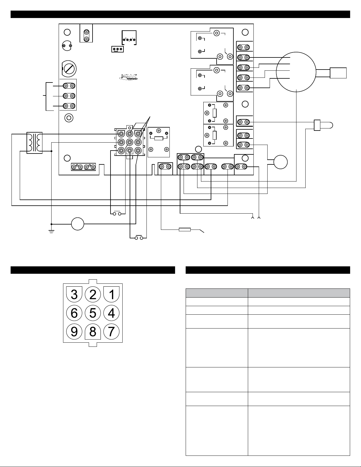
Wiring Diagram
TO ROOM
THERMOSTAT
115V
24V
XFMR
STATUS
24V HUM
W
G
R
TWIN
TEST
150
90
120
HEAT
DELAY
COIL
C
FORM-C
C
EAC
NC
NO
COOL
BLOWER
HI
HEAT
ICM280
ICM280
JUMPER NECESSARY
BETWEEN PINS 1 & 4
FOR 90+ SELECTION
CON2
P1
23
1
C
456
89 7
NO
NC
COIL
C
NO
C
C
PRI TRANS
FORM-C
C
NC
NO
NC
NO
NC
M1
M2
HSI
115V HUM
IND
BLK
VENT
MOTOR
MH
ML
LO
COM
BRN
BRN
HOT SURFACE
CAP
IGNITOR
F1
GAS VALVE
ATO 3A
LIMI
LIMO
LPS
PSI
PSO
90+O
GV
90+I
N/U
FS
NEUTRALS
FLAME
SENSOR
FS
PS
ICM280 Molex Plug Pin Out Trouble Shooting
Should be done by competent technician only.
Symptom Remedy
Fault light is blinking Check status led chart to determine problem
Blower fan runs constantly Check for open limit
No ame Check hot surface ignitor, verify voltage to hot
Furnace turns off when gas
valve turns on
1 = 90+ IN
2 = Pressure switch OUT
3 = 24V hot (R)
Furnace turns on and off
rapidly
4 = 90+ OUT
5 = Limit switch IN
Flame not being sensed Verify ame sense rod is clean, verify second-
6 = 24V common (C)
7 = Gas valve
Furnace turns off when
blower fan turns on
8 = Pressure switch IN
9 = Limit switch OUT
L2
115VAC SUPPLY
surface ignitor is present
1. Verify pressure switch is not opening, test
by placing temporary jumper across pressure switch when inducer fan turns on to
simulate a good pressure switch.
2. Verify secondary of transformer is adequately grounded.
Verify thermostat is functioning correctly, test
by removing thermostat wiring from ICM280
and placing temporary short between the R
and W terminals
ary of transformer is grounded
Verify thermostat is functioning correctly, test
by removing the thermostat wiring from the
ICM280 and place jumper from R to W. If
furnace functions properly then replace defective thermostat.
If furnace still functions incorrectly then check
the wiring of the secondary of the transformer,
swap connections at R and C at the ICM280.
 Loading...