

Page 1
Long Life EOS Analyzer
INSTRUCTION MANUAL
ENGLISH
COp 28
CO2% 6.2
C85
O2
CO Air
Status
Menu
Aux
Eff
X-Air
Free
CO
CO
2
Temp
Fuel
Date
Time
C85
CO2 CO TEMP
LONG LIFE EOS ANALYZER
1-800-547-5740 • Fax: (503) 643-6322
www.ueitest.com • Email: info@ueitest.com
1
1
Page 2
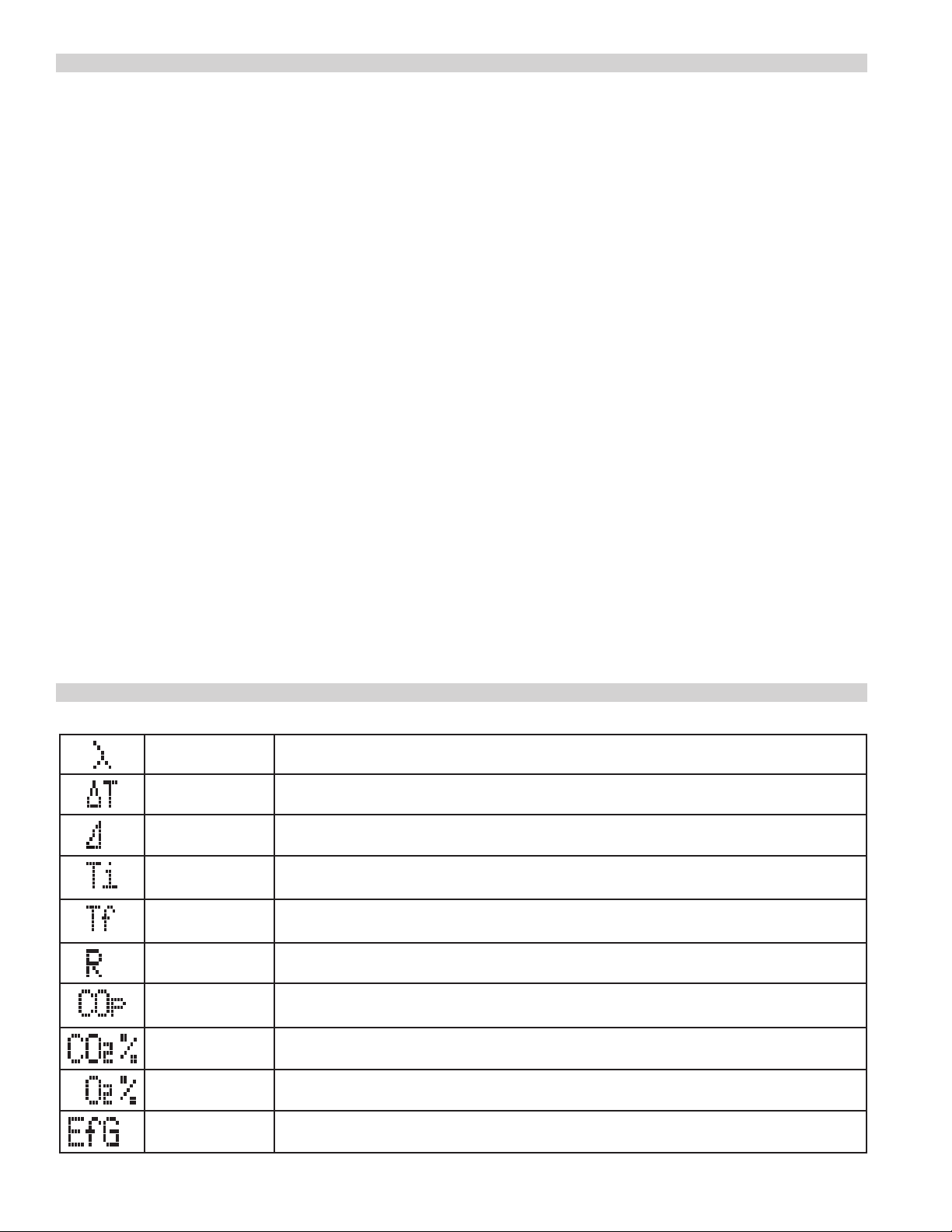
TABLE OF CONTENTS
Display Symbols ......................................2
Analyzer Overview ....................................3
Getting Started ........................................4
Safety Notes .......................................4
Warnings .........................................4
Menu / Setup .........................................4
Set Time ..........................................4
Set Date ..........................................4
Set Auxiliary Screen .................................5
Adjust Screen Contrast ...............................5
Customizeable Header (on print-outs) ...................6
Set Language ......................................6
Viewing and Printing Reports ..........................7
Print Setup ........................................7
Basic Fast Start (Operation) ............................8
Power On .........................................8
Select Fuel ........................................8
Connect Probe ......................................8
Select Parameter to View / Log / Print ..................8
Status ............................................8
Aux ..............................................8
Eff- X Air .........................................9
O2 CO Air Free ....................................9
CO2 CO ...........................................9
Temp ............................................9
Fuel ..............................................9
Date Time ........................................9
Where To Test ....................................10-11
What Results Are Generally Acceptable ................11
General Maintenance .................................12
Pre Test Checklist .................................12
Setting Inlet Temperature ...........................12
Analyzer Connections ..............................12
Emptying, Cleaning Water Trap ......................12
Changing Particle Filter .............................12
Replacing Batteries ................................13
Post Test ........................................13
Periodic Service ...................................13
Analyzer Re-Certification ............................13
Cleaning .........................................13
Other Important Factors Related To Combustion .........14
Combustion Measurement Terms ......................14
Specifications .......................................15
Electromagnetic Compatibility .........................15
Limited Warranty .....................................16
DISPLAY SYMBOLS
Excess Air Theoretical amount of air in excess of level needed to completely burn fuel
Delta T Differential temperature
Losses Losses calculated from oxygen and type of fuel
Inlet
Temperature
Flue
Temperature
Ratio CO to CO2 Ratio. Used to indicate the general condition of the combustion process
Carbon
Monoxide
Carbon Dioxide Carbon Dioxide measured in percentage%
Oxygen Oxygen calculated
Efficiency Calculated combustion efficiency based on net temperature, oxygen and fuel selected
Temperature measured and stored to calculate efficiency
Temperature measured by the flue probe or accessory k-type thermocouple
Carbon Monoxide measure in parts per million ppm
2
Page 3
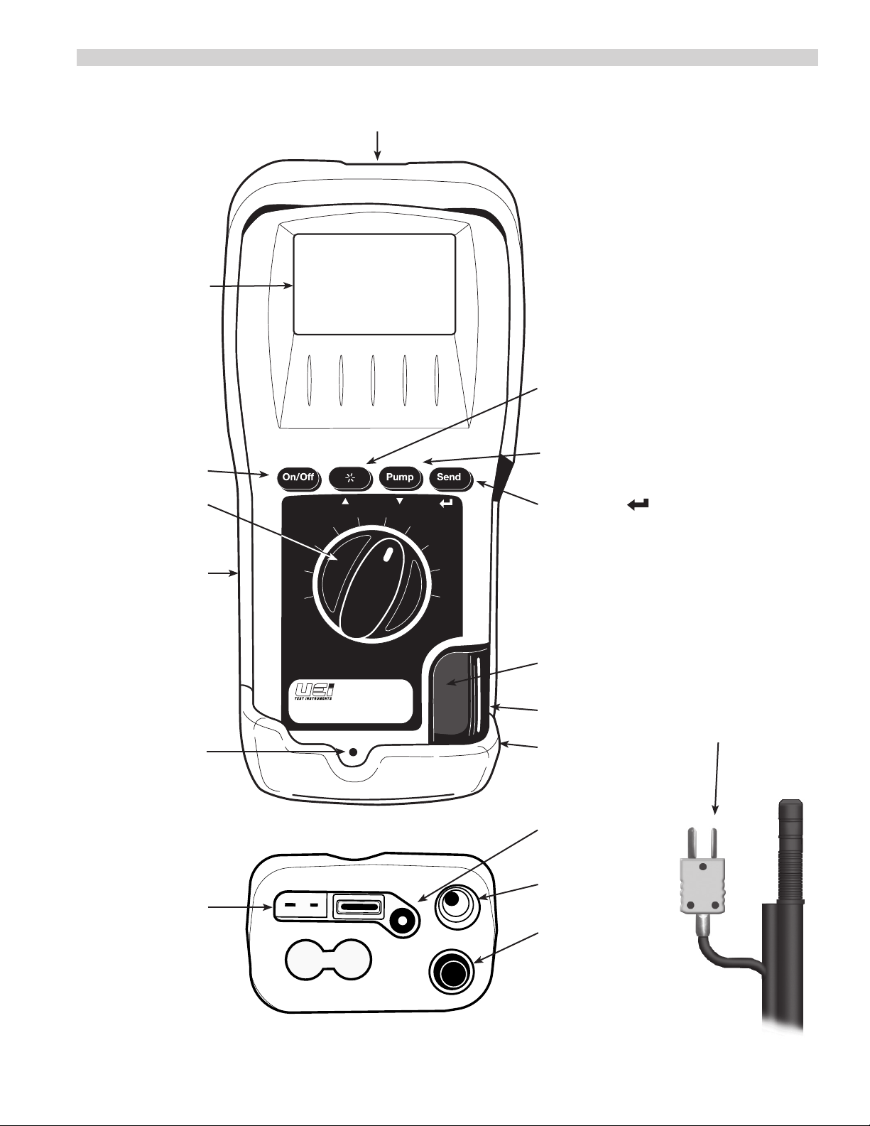
ANALYZER OVERVIEW
Infrared Printer Port
2 Line Backlit Display
On/Off Button
Rotary Test Selector Dial
Battery Compartments
in back under boot
AC Power/Charge
Indicator Light
COp 28
CO2% 6.2
O2
CO Air
Eff
X-Air
Aux
Status
Menu
CO2 CO TEMP
LONG LIFE EOS ANALYZER
Free
C85
CO
CO
2
Temp
Fuel
Date
Time
BACKLIGHT / “s“ UP Press to HOLD values
on display and navigate UP. Press and hold
to turn Backlight on/off.
PUMP / “t“ DOWN Press to turn
pump on/off and navigate DOWN
SEND/ENTER “ ”
to Select and Print
Particle Filter
Inside Water Trap
Water Trap
Flue Probe Temperature Plug
(Plugs into T1)
Narrow Pin MUST be on the
Right hand side.
Protective Rubber Boot
w/ built-in Magnets
Flue Probe
Gas Inlet Plug
Temperature
Connections
Flue Probe Temp: T1
Battery Charge
AC Adapter
Flue Gas
Inlet Connection
Water Trap
Drain
3
Page 4
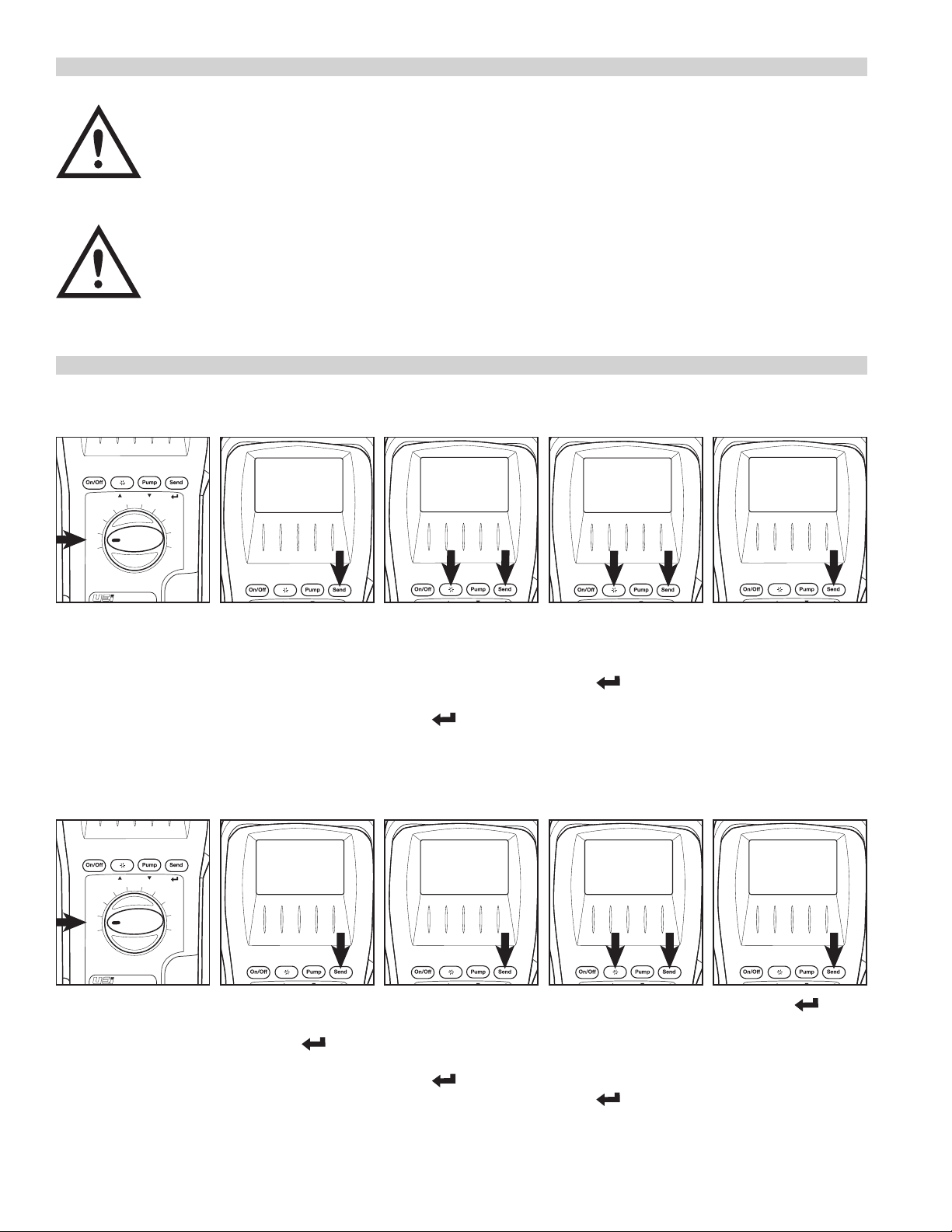
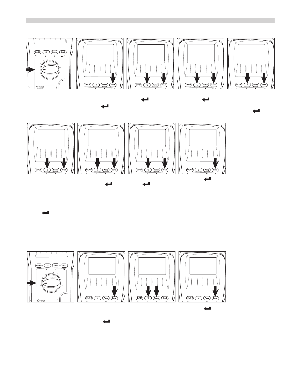
SET TIME
C85
MENU
SET TIME
C85
MENU
SET TIME
GETTING STARTED
SAFETY NOTES
Before using this meter, read all safety information carefully.
“WARNING” is used to indicate conditions or actions that may pose physical hazards to the user.
“CAUTION” is used to indicate conditions or actions that may damage this instrument.
WARNING!
This analyzer extracts combustion gases that may be toxic in relatively low concentrations. These gases are exhausted from
the back of the instrument. This instrument must only be used in well-ventilated locations. It must only be used by trained and
competent persons after due consideration of all the potential hazards.
MENU / SETUP
O2
CO Air
Eff
CO
2
Free
X-Air
CO
Aux
Status
Menu
Temp
Rotate dial to Menu
SET DATE
O2
CO Air
Eff
CO
2
Free
X-Air
CO
Aux
Status
Menu
Temp
MENU
SET TIME
Fuel
Date
Time
SET TIME shows press
“Send”
SET TIME
08:30:15
_
Clock displays with the
cursor underneath the first
digit. Press “s“ UP or
“t“ DOWN to increase or
decrease and press
SET TIME
09:30:15
_
Press “s“ UP or “t“
DOWN to increase or
decrease and press
ENTER “ ” to set and to
proceed to the next digit.
SET TIME
09:30:15
Press “Send” to complete
setting the time once all
digits are set.
ENTER “ ” to set and
proceed to the next digit.
MENU
SET DATE
Fuel
Date
Time
SET DATE
_
MM/DD/YY
SET DATE
_
01/21/15
SET DATE
01/21/15
_
Rotate dial to Menu
4
4
Press “s“ UP or “t“
DOWN to “SET DATE”
Press ENTER “ ”
Set date displays with
MM/DD/YY Press “s“ UP
or “t“ DOWN to select a
different format press
ENTER “ ” to proceed.
Use MM/DD/YY for North
American.
Date displays with the
cursor underneath the first
digit. Press “s“ UP or
“t“ DOWN to increase or
decrease and press
ENTER “ ” to set and
proceed to next digit.
Press ENTER “ ” to
complete setting the date
once all digits are set.
Page 5
SET AUXILIARY SCREEN (Aux)
C85
MENU
SET TIME
C85
MENU
SET TIME
MENU / SETUP (CONT.)
O2
CO Air
Eff
CO
2
Free
X-Air
CO
Aux
Status
Menu
Temp
Fuel
Date
Time
Rotate dial to Menu
AUXPAGE1
LINE 2
AUXPAGE1 LINE 2 shows
press “Send” to continue
to set line 2. Press
“s“ UP or “t“ DOWN
select between available
parameters and press
ENTER “ ” to set.
MENU
AUX
Press “s“ UP or “t“
DOWN to “AUX”
Press ENTER “ ”
AUXPAGE1
EXIT
AUXPAGE1 EXIT shows
press ENTER “ ” to
proceed.
AUX
PAGE1
AUX PAGE 1 shows press
ENTER “ ” to set.
AUX
PAGE2
AUX PAGE2 shows press
ENTER “ ” to proceed
to set page 2. Repeat the
same process as page 1 to
set page 2.
AUXPAGE1
LINE 1
AUXPAGE1 LINE 1 shows
press ENTER “ ” to
continue to set line 1.
AUX
EXIT
Press ENTER “ ” to exit.
AUXPAGE1
01/20/15
Press “s“ UP or “t“
DOWN select between
available parameters and
press ENTER “ ” to set.
ADJUST CONTRAST
X-Air
Aux
Status
Menu
Rotate dial to Menu
MENU
O2
CO Air
Eff
CO
2
Free
CO
Temp
Fuel
Date
Time
CONTRAST
Press “s“ UP or “t“
DOWN to “CONTRAST”
Press ENTER “ ”
CONTRAST
SET 100
Press “s“ UP or “t“
DOWN to adjust screen
contrast. NOTE: The higher
CONTRAST
SET 150
Press ENTER “ ” to exit.
the value the lighter the
digits appear
5
5
Page 6

C85
MENU
SET TIME
CUSTOMIZABLE HEADER (ON PRINTOUTS)
O2
C85
MENU
SET TIME
MENU / SETUP (CONT.)
O2
CO Air
Eff
CO
2
Free
X-Air
CO
Aux
Status
Menu
Temp
Rotate dial to Menu
_PHONE
NUMBER
MENU
HEADER
Fuel
Date
Time
Press “s“ UP or “t“
DOWN to “HEADER”
Press ENTER “ ”
HEADER
HEADER1
Press “s“ UP or “t“
DOWN to select HEADER 1
Press ENTER “ ” to
proceed.
_HEADER
SAMPLE
The existing HEADER 1
will display with the cursor
underneath the first digit.
Press “s“ UP or “t“
DOWN to change and
HEADER
HEADER2
Repeat the process for
HEADER 2 and press
ENTER “ ” to proceed.
press ENTER “ ” to set
and continue to the next
digit. Press ENTER “ ”
to proceed.
HEADER
EXIT
The existing HEADER 2
will display with the cursor
underneath the first digit.
Press “s“ UP or “t“
DOWN to change and
press ENTER “ ” to set
and continue to the next
digit. Press ENTER “ ”
to proceed.
SET LANGUAGE
O2
CO Air
Eff
CO
2
Free
X-Air
Aux
Status
Menu
Rotate dial to Menu
CO
Press ENTER “ ” to exit.
MENU
Temp
Fuel
Date
Time
LANGUAGE
Press “s“ UP or “t“
DOWN to “LANGUAGE”
Press ENTER “ ”
LANGUAGE
ENGLISH
Press “s“ UP or “t“
DOWN to change language
and press ENTER “ ” to
set and exit
6
Page 7

VIEWING AND PRINTING REPORTS
C85
MENU
SET TIME
C85
MENU
SET TIME
C85
MENU
SET TIME
MENU / SETUP (CONT.)
O2
CO Air
Eff
CO
2
Free
X-Air
CO
Aux
Status
Menu
Rotate dial to Menu
O2
CO Air
Eff
CO
2
Free
X-Air
CO
Aux
Status
Menu
MENU
Temp
Fuel
Date
Time
Press “s“ UP or “t“
DOWN to “REPORT”
Press ENTER “ ”
REPORT
Press “s“ UP or “t“
DOWN to “VIEW” press
ENTER “ ” to proceed.
REPORT
VIEW
LOG 01
01/21/15
Press and hold “s“ UP
or “t“ DOWN to select
log to view (LOG 01, LOG
02). Press “s“ UP or “t“
LOG 02
01/25/15
Press “Send” to print
LOGGED results. press
ENTER “ ” again to
abort.
DOWN to scroll and view
parameters on second line.
MENU
Temp
Fuel
Date
Time
REPORT
REPORT
DEL ALL
DEL ALL
YES
Rotate dial to Menu
PRINT SETUP
Eff
X-Air
Aux
Status
Menu
Rotate dial to Menu
CO Air
Press “s“ UP or “t“
DOWN to “REPORT”
Press ENTER “ ”
Press “s“ UP or “t“
DOWN to “DEL ALL”
Press ENTER “ ” to
proceed.
Press “s“ UP or “t“
DOWN to select Yes or No
Press ENTER “ ” to
proceed. Analyzer will
automatically return to the
menu.
Printer Options
MENU
O2
CO
2
Free
CO
Temp
Fuel
Date
Time
PRINTING
PRINTING
KMIRP
• KMIRP2 for legacy
infrared thermal printer
• IRP-3 for easy-load fast
printer
NOTE: If using the KMIRP2
printer and incomplete
reports are printing check
Press “s“ UP or “t“
DOWN to “PRINTING”
Press ENTER “ ”
Press “s“ UP or “t“
DOWN to select printer.
Press ENTER “ ” to
the print setup
select. Analyzer will
automatically return to the
menu.
7
7
Page 8

BASIC FAST START (OPERATION)
01/21/15
TIME 90
SET FUEL
NAT GAS
COp 28
CO2% 6.2
1. POWER ON
01/21/15
O2
CO Air
Eff
CO
2
Free
X-Air
CO
Aux
Status
Menu
Temp
Fuel
Date
Time
Power on in area of fresh air and allow to countdown. On
sealed combustion appliances (ducted inlet) connect flue
probe and power on outside and allow to countown to set
inlet temperature. (see page 12)
TIME 90
2. SELECT FUEL
O2
CO Air
Eff
CO
2
Free
X-Air
CO
Aux
Status
Menu
Rotate test selector to Fuel.
Temp
Fuel
Date
Time
SET FUEL
NAT GAS
Press “s“ UP or “t“ DOWN
to scroll and press “Send” to
select desired fuel. Bottom
line displays selected fuel.
3. CONNECT PROBE 4. SELECT PARAMETER TO VIEW / LOG / PRINT
COp 28
O2
CO Air
Eff
CO
2
Free
X-Air
CO
Aux
Status
Menu
Temp
Fuel
Date
Time
CO2% 6.2
Connect flue probe
thermocouple connector to
T1, and connect flue probe to
water trap as shown above.
Status
Menu
BAT
CAL 300
O2
CO Air
Eff
CO
2
Free
X-Air
CO
Aux
Temp
Fuel
Date
Time
C85
Insert Flue Probe in stack.
Adjust the cone so the end of
Rotate selector to desired
test.
the probe is approximately at
the center of the stack
(4” stack adjust cone to
aprox. 2” from end of probe.)
Status Aux
Rotate selector to Status.
The status menu shows
battery life and the number
of days until suggested
re-certification. (CAL)
12:34:56
01/02/03
O2
CO Air
Eff
CO
2
Free
X-Air
CO
Aux
Status
Menu
Temp
Fuel
Date
Time
O2
CO Air
Eff
CO
2
Free
X-Air
CO
Press “Send” to print results
or press and hold “Send” to
log results from any screen.
Rotate selector to Aux.
The auxilliary menu shows
user defined parameters. The
display alternates between
page 1 and page 2.
To set up the auxilliary menu
see instructions on page 5.
C85
CO2 CO TEMP
LONG LIFE EOS ANALYZER
C85
CO2 CO TEMP
LONG LIFE EOS ANALYZER
8
Page 9

Eff / X-Air
O2 CO Air Free
EfG 88.1
X 31.4
O2
CO Air
Eff
CO
2
Free
X-Air
CO
C85
Temp
Fuel
Date
Time
Aux
Status
Menu
CO2 CO TEMP
LONG LIFE EOS ANALYZER
COp 28
CO2% 6.2
O2
CO Air
Eff
CO
2
Free
X-Air
CO
C85
Temp
Fuel
Date
Time
Aux
Status
Menu
CO2 CO TEMP
LONG LIFE EOS ANALYZER
Rotate selector to Eff X-Air.
The Eff/X-Air screen shows
calculated combustion efficiency
using a Gross Condensing
calculation and excess air.
When below condensing
temperature the efficiency
calculation includes and
estimated energy recovered
during condensation that
increases combustion efficiency.
This calculated value is not
the same as AFUE.
Excess air is a calculated value
representing the amount of
air above the level needed to
completely burn all of the fuel.
NOTE: Negative net temperature
will result in efficiency greater
than 100%
CO2 CO
Rotate selector to CO2 CO.
The CO2 / CO screen is a
direct display of measured
gases. Carbon dioxide (CO2)
is displayed in percentage
(%), carbon monoxide (CO) is
displayed in parts per million
(ppm).
These two measurements are
commonly referenced target
values for appliance set up.
O2% 21.9
COa -0>-
O2
CO Air
Eff
CO
2
Free
X-Air
CO
C85
Temp
Fuel
Date
Time
Aux
Status
Menu
CO2 CO TEMP
LONG LIFE EOS ANALYZER
Tf 75.9F
Ti 69.9F
O2
CO Air
Eff
CO
2
Free
X-Air
CO
C85
Temp
Fuel
Date
Time
Aux
Status
Menu
CO2 CO TEMP
LONG LIFE EOS ANALYZER
Rotate selector to O2 CO Air
Free.
The O2/CO Air free screen
shows the calculated amount
of O2 (from CO2 measured
and fuel selected), and CO
Air Free.
CO Air free is a calculated
value for carbon monoxide
as if there were no dilution
from air.
COppm =
[20.9 / (20.9 - O2 measured)]
Temp
Rotate selector to Temp.
The temperature screen
will display values for flue
temperature (Tf) and inlet
temperature (Ti). If inlet
temperature was set during
initial power on, it will
display that temperature. If
using ambient temperature
you will observe the internal
handset temperature.
Note: The sample pump will
stop when CO is less than
40ppm.
SET FUEL
NAT GAS
O2
CO Air
Eff
CO
2
Free
X-Air
CO
C85
Temp
Fuel
Date
Time
Aux
Status
Menu
CO2 CO TEMP
LONG LIFE EOS ANALYZER
Fuel
Rotate test selector to Fuel.
The fuel selector position will
display the current fuel being
used for calculations.
Press “s“ UP or “t“ DOWN
to scroll and press ENTER
“ ” to select desired fuel.
Bottom line displays selected
fuel selected for calculations
Date Time
13:27:46
01/21/15
O2
CO Air
Eff
CO
2
Free
X-Air
CO
C85
Temp
Fuel
Date
Time
Aux
Status
Menu
CO2 CO TEMP
LONG LIFE EOS ANALYZER
Rotate test selector to Date
Time.
Display shows internal clock
and the date.
9
Page 10

WHERE TO TEST
Air Conditioning / Heat Pump
Suction Line:
• Temperature
Verify proper:
• Static Duct Pressures
• Temperature Differential
• Static Pressure Drop Across Coils
to condensing unit
Boiler & Water Heaters & High Efficiency Modulating Hot Water Systems
Boiler
Verify proper combustion:
• O2
• CO Air Free
• Stack Temp
• Stack Draft
• SSE
Water Heater
Draft
Verify proper combustion:
• O2
• CO
• Stack Temp
• Efficiency
HE Boiler Instant
Water Heaters
Draft
Verify proper
combustion:
• O2
• CO
• Stack Temp
• Efficiency
Hi / Low fire Gas
Pressure
Send and Return
Water temp
Furnaces: 80% Furnaces: 90%
80% Furnace
Verify proper combustion:
• O2
• CO
• Stack Temp
• Vent Pressure
• Efficiency
90%+ Furnace
Verify proper combustion:
• O2
• CO
• Stack Temp
• Vent Pressure
• Efficiency
Verify/Set Up
• Gas Pressure
Test
• Limit Switch
• Pressure Switch
Verify proper operation:
• Static Duct Pressure
• Temperature Rise
• AC side Static Pressure
Drop across coils
10
Verify/Set Up
• Gas Pressure
Test
• Limit Switch
• Pressure Switch
Verify proper operation:
• Static Duct Pressure
• Temperature Rise
• AC side Static Pressure
Drop across coils
Page 11

WHERE TO TEST (CONT.)
Furnaces (continued): Atmospheric, Gas & Oil
Atmospheric Furnace
Draft
Verify proper
• Temperature Rise
• AC side Static Pressure
Drop across coils
Verify proper combustion:
• O2
• CO
• Stack Temp
• Efficiency
Oil Furnace
Verify proper combustion:
• O2
• CO
• Stack Temp
• Stack Draft
• Efficiency
Natural Gas & Propane
Verify proper combustion:
• O2
• CO
• Stack Temp
• Vent Pressure
• Efficiency
Test
• Limit Switch
• Pressure Switch
Set Up
• Gas Pressure
Verify proper:
• Static Duct Pressure
• Temperature Rise
• AC side Static Pressure
Drop across coils
Test & Verify:
• Smoke
Set Up
• Over Fire Draft
Verify proper
• Static Duct Pressure
• Temperature Rise
• AC side Static Pressure
Drop across coils
WHAT RESULTS ARE GENERALLY ACCEPTABLE
Atmospheric Gas Fired Burners
• Oxygen ................................ 7 to 9% O2
• Stack Temperature ..................... 325 to 500°F
• Draft (Water Column Inches) ............ -.02 to -.04wc”
• Carbon Monoxide (parts per million) ........... <100ppm
Gas Fired Power Burners
• Oxygen ................................ 3 to 6% O2
• Stack Temperature ..................... 275 to 500°F
• Stack Draft (Water Column Inches) ....... -.02 to -.04wc”
• Overfire Draft (Water Column Inches) ........... -.02wc”
• Carbon Monoxide (parts per million) ........... <100ppm
Oil Fired Burners (#2 Oil Fuel)
• Oxygen ................................ 4 to 7% O2
• Stack Temperature ..................... 325 to 600°F
• Stack Draft (Water Column Inches) ....... -.04 to -.06wc”
• Overfire Draft (Water Column Inches) ........... -.02wc”
• Carbon Monoxide (parts per million) ........... <100ppm
• Smoke .......... 0 (or manufacturer’s recommendation)
Positive Overfire Gas & Oil
• Oxygen ................................ 3 to 9% O2
• Stack Draft (Water Column Inches) ....... -.02 to -.04wc”
• Overfire Draft (Water Column Inches) .... +0.4 to +0.6wc”
• Carbon Monoxide (parts per million) ........... <100ppm
NOTE: Follow manufacture guidelines for the specific equipment being
serviced.
Typical Excess Air Level
O2% (measured) Excess Air %
Natural gas 3% 16.7%
Light Oil 5% 31%
Coal 8% 62%
11
Page 12

GENERAL MAINTENANCE
• Re-certify your instrument annually to ensure it meets original performance specifications
• Keep your instrument dry. If it gets wet, wipe dry immediately. Liquids can degrade electronic circuits
• Whenever practical, keep the instrument away from dust and dirt that can cause premature wear
• Although your instrument is built to withstand the rigors of daily use, it can be damaged by severe impacts. Use reasonable caution
when using and storing the meter
PRE TEST CHECKLIST
• Clean particle filter
• Water trap and probe line are empty of water
• Power on and zero
• All hose and thermocouple connections are properly secured
• Flue gas probe is sampling ambient FRESH air
• Water trap is fitted correctly to the instrument
• Flue temperature plug is connected
SETTING INLET TEMPERATURE
• Turn on and zero the analyzer with out the flue probe connected to use ambient temperature
• Connect flue probe thermocouple to T1 during zero countdown to store probe tip temperature as inlet (ducted system)
ANALYZER CONNECTIONS
WARNING!
Turning the pump off while the probe is in the flue will leave toxic gases inside
the analyzer. Once data has been printed or copied it is advisable to purge the
unit with fresh air as soon as possible. To do this remove the probe from the flue
and turn ON the pump. Always allow the readings to return to zero (20.9 for O2)
prior to shutting the unit off. The meter will not switch off until the CO reading
is below 20 ppm.
WARNING!
The probe will be hot from flue gases. Remove the probe from the flue and allow
it to cool naturally. Do not immerse the probe in water, as this will be drawn into
the analyzer and damage the pump and sensors. Once the probe is removed from
the flue and the readings have returned to ambient levels hold down “On/Off”
and switch off the analyzer. The instrument will count down from 30 to switch
off. If you pressed “On/Off“ by mistake, pressing “Send“ will return you to normal
operation.
EMPTYING & CLEANING THE IN-LINE WATER TRAP
The in-line water trap should be checked and emptied on a regular basis. Water vapor will condense in
the probe line, which may cause the water trap to fill suddenly if the probe is moved. Care should be
taken at all times.
Carefully remove the rubber plug from the bottom of the water-trap housing. Dispose of the condensate
in a suitable drain, care must be taken as it could be acidic. If condensate spills onto the skin or clothing,
clean off immediately using fresh water, seek medical advice if problems occur. Ensure plug is replaced
before performing combustion tests. Note: O2 reading will be high if the Water Trap Plug is not in place.
CHANGING THE PARTICLE FILTER
This is a very important part of the analyzer and should be changed regularly. It prevents dust and dirt
particles from entering the pump and sensors that will cause damage. The filter MUST be changed when
it appears discolored on the inner surface.
NOTE: Take care when inserting
the temperature probes as the
pins are polarized. Insert with the
smaller pin (+) to the right.
NOTE: Do not insert anything
into programming port.
Remove water-trap assembly from the analyzer as shown above. Remove the filter and plastic holder
from the housing. Discard the filter element but keep the holder to fit to the new filter. Clean the inside
of the filter housing with a suitable soft cloth. Fit the holder onto the new filter element and then insert
into the housing. Refit the housing onto the analyzer.
12
Page 13

REPLACING THE BATTERIES
This meter has been designed for use with both alkaline and rechargeable Nickel Metal Hydride (NiMH) batteries. No other types are
recommended. The analyzer is supplied with 4 “AA” size alkaline batteries. These should be installed into the instrument as shown in the diagram
indicated on the back of the unit.
CAUTION!
Take great care when installing the batteries to observe correct polarity.
Always check the meter for operation immediately after installing
new batteries.
Using Re-Chargeable Batteries
The battery charger must only be used when NiMH batteries are fitted. Alkaline batteries are not re-chargeable. Attempting to recharge alkaline
batteries may result in damage to the product and may create a fire risk.
Battery Charging
Ensure that you use the correct charger. This unit uses a 9V DC regulated charger. Ensure that the batteries are fitted in the correct manner, and
then charge for at least 16 hours. Subsequent charges should be overnight. NiMH batteries may be charged at any time, even for short periods
to conduct testing.
WARNING!
Under NO circumstance should you expose batteries to extreme heat or fire as they may explode and cause injury. Always
dispose of old batteries promptly in a manner consistent with local disposal regulations.
POST TEST
O2% 20.9
COa -0>-
Remove the probe from the flue and allow the analyzer to purge
with fresh air until readings return to zero. - O2 to 20.9%, CO to
Zero (Be careful as the probe tip will be HOT)
PERIODIC SERVICE
WARNING!
Repair and service of this instrument is to be performed by qualified personnel only. Improper repair or service could result in
physical degradation of the instrument. This could alter the protection from personal injury this meter provides to the operator.
Perform only those maintenance tasks that you are qualified to do.
ANNUAL RE-CERTIFICATION
Drain water trap by unplugging
the drain plug and shake to
get excess water out.
Check particle filter for dirt
and any other sediment and
replace if necessary.
While the CO sensor has an expected life of more than five years in normal use it is recommended that the analyzer is re-certified at least annually.
This is so that long-term drift on the sensor and electronics can be eliminated. Local regulations may require more frequent re-calibration and
users should check with appropriate authorities to ensure they comply with relevant guidelines.
CLEANING
Periodically clean your instruments case using a damp cloth. DO NOT use abrasive, flammable liquids, cleaning solvents, or strong detergents as
they may damage the finish, impair safety, or effect the reliability of the structural components.
13
Page 14

OTHER IMPORTANT FACTORS RELATING TO COMBUSTION
The three T’s of combustion
Time: Amount of time that the fuel and oxygen are together in the combustion chamber
Temperature: How high the temperature is determines the rate of oxidation, or speed of the combustion
Turbulence: How well the fuel and air are mixed
These three factors are all interrelated, and will move your results along the combustion curves.
COMBUSTION MEASUREMENT TERMS
Other parameters measured include net temperature, draft and efficiency.
Net Temperature
Net temperature is the difference between the combustion air entering the combustion chamber and the flue gas temperature past the heat exchange. This
is used to determine how efficient the system is extracting heat from the combustion process in addition to the performance of the combustion process. On
sealed systems that have ducted inlet air for combustion air, the net temperature must compare this air stream temperature with the flue gases. If the appliance simply uses room air for the combustion air, our analyzers have an internal temperature sensor in the handset, so it will use this temperature when
calculating net temperature. The most accurate results for efficiency are obtained when measuring flue gases at the point where flue temperature (not flame
temperature) is the highest.
Draft
Draft is the difference between the ambient pressure level and the pressure level in the flue.
This is created either by the natural buoyancy of the hot gases created in combustion lifting, or by an inducer fan that assists the flow of flue gases up the
stack. Most combustion equipment will specify the amount of draft that is required for proper operation. Draft helps draw combustion air into the combustion
chamber, and also helps in mixing the fuel and oxygen. Without proper draft, the combustion process can spill poisonous by-products into the space where the
appliance is located. This can be a risk to those in the area, or create a danger to residents or employees working near the combustion equipment.
Efficiency
Efficiency is a measure of how well the fuel is burned to create heat, and how well the generated heat is captured for the intended use.
The information used to create this value are based on the fuels heating value, the heat lost up the flue and the gas components in the flue gas. The original
method to determine efficiency included many manual methods and lookup charts. As an example you would measure the CO2 level and the stack temperature and then reference a slide scale that would give you the relative efficiency number. UEi’s electronic combustion analyzers perform the measurements
on a continuous basis, and can calculate the efficiency as adjustments are being made. Combine this with a printout and you are able to provide a before
and after comparison of the combustion equipment in relatively little time as part of normal servicing. Combustion efficiency is not the same as AFUE
(annual fuel usage efficiency). AFUE is not measurable with any portable flue gas analyzer.
Combustion Efficiency Calculations
This identifies three sources of loss associated with fuel burning:
•Losses due to flue gases:
Dry Flue gas loss, Moisture and hydrogen,
Sensible heat of water vapor, Unburned gas
• Losses due to refuse:
Combustible in ash, riddling and dust
• Other losses:
Radiation, convection, conduction other unmeasured losses
Net efficiency calculations assume that the energy contained in the water vapor (formed as a product of combustion and from wet fuel) is recovered and the
wet loss term is zero. Gross efficiency calculations assume that the energy contained in the water vapor is not recovered. Since the fuel air mixture is never
consistent there is the possibility of unburned/partially unburned fuel passing through the flue. This is represented by the unburned carbon loss. Losses due to
combustible matter in ashes, riddling, dust and grit, radiation, convection and conduction are not included.
CO Air Free
Certain standards ( ANSI Z21.1) for Carbon Monoxide are stated in terms of air-free. Air-free refers to the concentration of CO in combustion gases undiluted
with flue, or other gases containing little CO. This value is computed using an equation that takes into account the O2 concentration of the flue gas.
• If 5% O2 is measured (O2m) in the flue then the CO gas value will be recalculated as if 0% were measured. The equation for air-free is
as follows:: COaf = CO PPM x [(20.9) / (20.9 - O2m)]
• In our example if a reading of 325 PPM were measured then the air-free value would be calculated as follows:
COaf = 325 PPM x [(20.9) / (20.9 - 5)] COaf = 325 PPM x [(20.9) / (15.9)] COaf = 427
We may be given a limit on our gas range by the local authority, which stated that we must not emit more than 400-PPM Carbon Monoxide air-free. In the
example we would be breaking the limit and corrective action should be taken to reduce the level of CO. Air-free values prevent false readings being submitted, e.g. allowing more air into the boiler will increase the oxygen level in the flue and dilute any toxic gas reading. Air-free referencing gives readings as if
they were undiluted.
14
Page 15

SPECIFICATIONS
Parameter Range Resolution Accuracy
Temperature Measurements
Flue Temperature 32 - 1112˚F (0 - 600˚C) 1.0˚ F/C ±5˚F (2.0˚C) ±0.3% reading
Inlet temperature 32 - 212˚F (0 - 100˚C) 1.0˚ F/C ±1˚ F/C ±0.3% reading
Temp (Nett)
*2
32 - 1112˚F (0 - 600˚C) 1.0˚ F/C ±5˚F (2˚C) ±0.3% reading
Gas Measurements
Carbon Monoxide (CO) 0 - 1999 ppm 1 ppm ±5ppm <100ppm
±5% rdg >100ppm
Carbon Dioxide (CO2) 0 - 30% 0.1% ±0.3%
Calculations
Oxygen (O2) 0 - 21% 0.1% ±0.2%
Efficiency 0 - 99.9% 0.1% ±1.0%
Excess Air 0 - 250% 0.1% ±0.2%
GENERAL SPECIFICATIONS
• Operating Altitude: 2000m (6,561 ft.)
• Storage Altitude: 10,000m (32,808 ft.)
• Operating Temperature: 32°F to 104°F (0°C to 40°C) at 10 - 90% R.H
• Pollution Degree: 2
• Dimensions: Handset: 7.9” (200mm) x 3.5” (90mm) x 1.8” (45mm)
Probe: (L) 7.9” (300mm) x (D) 0.25” (6mm) with 7.8” (200mm)
6ft (3m) neoprene hose
• Weight: 2.2lbs (1kg)
• Certifications: EMC EN 50081-1, EN 50082-1, CE
• Battery Type: 4 x 1.5V AAA
• Power Supply Input: 110V AC Output: 9V DC Regulated
ELECTROMAGNETIC COMPATIBILITY (EMC)
This product has been tested for compliance with the following generic standards: EN 50081-1, EN 50082-1 and is certified to be compliant.
The European Council Directive 89/336/EEC requires that electronic equipment does not generate electromagnetic disturbances that exceed defined levels and
has an adequate level of immunity to enable it to be operated as intended.
Since there are many electrical products in use that pre-date this Directive and may emit electromagnetic radiation in excess of the standards defined in the
Directive there may be occasions where it would be appropriate to check the analyzer prior to use. The following procedure should be adopted.
• Go through the normal start up sequence in the location where the equipment is to be used
• Switch on all localized electrical equipment that might be capable of causing interference
• Check that all readings are as expected (a level of disturbance in the readings is acceptable)
• If not, adjust the position of the instrument to minimize interference or switch off, if possible, the offending equipment for the duration of the test
At the time of writing this manual (January 2015) UEi is not aware of any field based situation where such interference has ever occurred and this advice is
only given to satisfy the requirements of the Directive.
15
Page 16

SERVICE
IMPORTANT: PRODUCT REGISTRATION
Register your product online at www.ueitest.com and click the PRODUCT REGISTRATION banner. This allows us to notify you when your analyzer has upgrades
available or when recertification is due.We manufacture industry-leading products for professionals like you; please help us to ensure your product is always
fit for purpose by registering your new purchase online - it only takes a few minutes.
IMPORTANT: RE-CERTIFICATION
While the CO sensor has an expected life of more than 5 years in normal use, it is recommended that the analyzer is recertified annually. The C85 analyzer
typically requires an annual recertification each of the first four years and full recertification on the 5th year pending use. This eliminates long term drifting of
the sensor and electronics. Local regulations may require more frequent calibration and users should check with appropriate authorities to ensure compliance.
UEi Test Instruments offers 2 kinds of recertification services.
Annual: Calibration of all installed sensors
Full: Replacement of all applicable sensors
Both services offer:
Full system, 30-point inspection with replacement of any failed parts.
Firmware and/or software upgrades as needed.
Certificate of calibration provided for record keeping.
Recertification work report to document work completed.
Units returned cleaned with paid return freight.
All units are recertified by trained professionals, which eliminate the legal liability of self-installed sensors. In the USA we have two recertification locations, one in Indianapolis, IN the second in Portland, OR. For Canadian customers we have a recertification service center in Vancouver, BC, which is ISO/IEC
17025:2005 accredited and offers NIST certification services for select products. All recertification services are warranted for one year.
Save time with online recertification check-in by visiting www.ueitest.com and click the SERVICE REQUEST banner and filling out the form.
Our current recertification prices can be found on the SERVICE section of our web site. Up front pricing means NO surprises.
LIMITED WARRANTY
The C85 combustion analyzer is warrantied for five years including sensors.
If within the warranty period your instrument should become inoperative from such defects, the unit will be repaired or replaced at UEi’s option. This warranty
covers normal use and does not cover damage which occurs in shipment or failure which results from alteration, tampering, accident, misuse, abuse, neglect
or improper maintenance (calibration). Batteries and consequential damage resulting from failed batteries are not covered by warranty. Any implied warranties, including but not limited to implied warranties of merchantability and fitness for a particular purpose, are limited to the express warranty. UEi shall not be
liable for loss of use of the instrument or other incidental or consequential damages, expenses, or economic loss, or for any claim or claims for such damage,
expenses or economic loss. A purchase receipt or other proof of original purchase date will be required before warranty repairs will be rendered. Instruments
out of warranty will be repaired (when repairable) for a service charge. Contact UEi for specific warranty and service information. This warranty gives you specific legal rights. You may also have other rights which vary from state to state.
1-800-547-5740 • Fax: (503) 643-6322
www.ueitest.com • Email: info@ueitest.com
Copyright © 2015 UEi. All Rights Reserved 17093 02/15
USA
1-877-475-0648 • Fax: (604) 278-8299
www.ueitest.com • Email: infocanada@ueitest.com
8030 SW Nimbus Ave.
Beaverton, OR 97008
CANADA
150-13571 Verdun Place
Richmond, B.C.
V6V 1W5
+44 1707 375550 • Fax: +44 1707 393277
EUROPE
www.ueitest.com • Email: info@ueitest.com
 Loading...