


Service/Installation Manual
Hotel Dispenser
Model - CD300
Mile High Equipment
11100 East 45th Ave
Denver, Colorado 80239
Part Number 9081292-01 |
Print Date 04/02 |
|

Introduction |
CD300 |
To the owner or user: This product manual is a source of information about the installation, start up, cleaning, maintenance and repair of the product.
Table of Contents |
|
Introduction |
Page 1 |
Specification/Limitations |
Page 2 |
Diagrams |
Page 3 |
Uncrating |
Page 4 |
Ice Machine Installation |
Page 5 |
Utility Connections |
Page 6 |
Initial Start Up and Use |
Page 7 |
Sanitation and Maintenance |
Page 8 |
Component Identification |
Page 9 |
Maintenance |
Page 10 |
Service Diagnosis |
Page 11 |
Adjustments |
Page 12 |
Removal and Replacement |
Page 13 |
Wiring Diagram-Push Button |
Page 14-15 |
Wiring Diagram-Coin Mechanism |
Page 16-17 |
Wiring Diagram-Key Card |
Page 18-19 |
Before Calling For Service Information |
Page 20 |
Warranty Information |
Page 2 |
Ice-O-Matic 11100 E. 45th Ave.
Denver, Co. 80239 800-423-3367
The CD300 Service Parts Manual is available separately, Part Number 9081293-01
Page 1
Specifications |
CD300 |
Specifications and Limitations
This dispenser is designed to dispense cubed ice only and to be installed and operated indoors, in a controlled enviroment. Its minimum and maximum operating temperature limits are the same as those for the ice machine.
Limitations:
Must meet the same limitations as the cuber installed on top of it.
Must allow adaquate space for air flow when using and air cooled machine.
Must allow space for utility connection at the back.
Must have a drain.
The CD300 is compatable with Ice-O-Matics cuber models ICE250, ICE400, ICE500 and ICE600.
A thermostatic bin control kit is required on all ICE Series cubers. (Part Number 1051020-02)
Operating Requirements: |
Minimum |
Maximum |
Air Temperature |
50 F |
100 F |
Voltage |
104 VAC |
126 VAC |
Check the nameplate, located on the back of the dispenser cabinet for specific information.
Ice-O-Matic ice machines are not designed for outdoor installations.
Machine requires voltage indicated on rating nameplate. Failures caused by improper voltage are not considered factory defects. Extended periods of operation at temperatures exceeding limitations constitutes misuse under the terms of the Ice-O-Matic Manufacture’s Limited Warranty, resulting in a loss of warranty coverage. Specifications and design are subject to change without notice.
Ice-O-Matic assumes no liability of any kind for products manufactured by Ice-O-Matic that have been altered in any way, including the use of any parts and/or other components not specifically approved by Ice-O-Matic.
The CD300 dispenser has a 2 year Parts warranty and a 2 year Labor Warranty.
Model |
Electrical |
Amps |
Vend Type |
Finish |
CD300P |
115/60/1 |
2.2 |
Push Button |
Stainless Steel |
CD300C |
115/60/1 |
2.2 |
Coin (25¢ Only) |
Stainless Steel |
CD300K |
115/60/1 |
2.2 |
Key Card |
Stainless Steel |
Page 2

Diagrams |
CD300 |
Page 3
Uncrating |
CD300 |
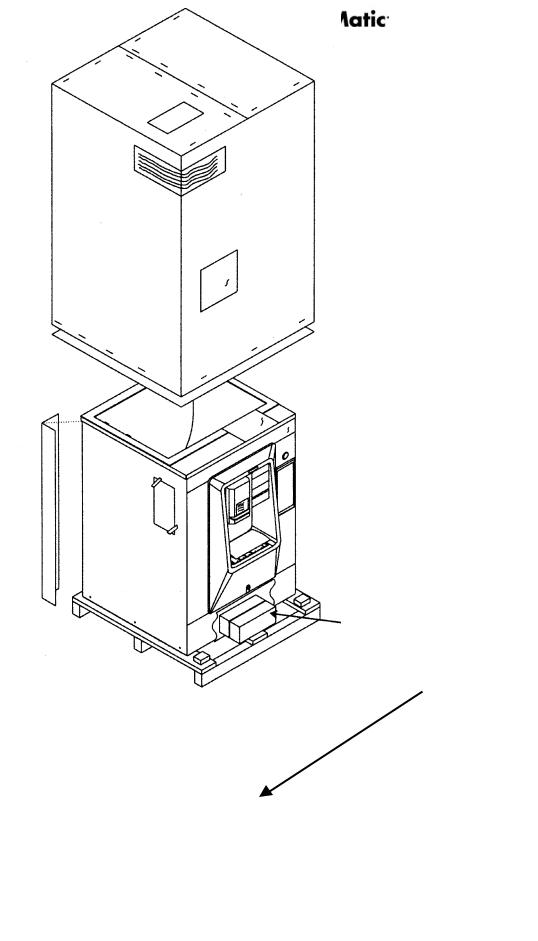
Remove the carton from the skid. Cut the plastic straps that secure the leg kit to the skid and remove the box.
Use the dispenser carton as a cushion and lay the dispenser down on its back. Remove the bolts holding the skid to the machine, and separate the skid from the dispenser.
Install the dispenser legs into the threaded holes in the dispenser bottom. Screw them in hand tight.
Return the unit to an upright position.
There are keys taped to the grill below the ice dispensing area. Remove them and save them for later use.
Remove all shipping material and tape. Record the model and serial number on the Warranty Registration form.
Leg Package Location
Page 4
Ice Machine Installation |
CD300 |
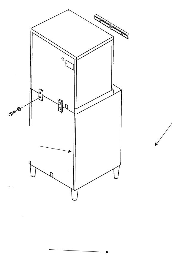
All models: Place the dispenser in the location where it will be used. Level the top edge of the dispenser front to back and left to right with the adjustable legs.
Place the ice machine on the dispenser and secure it to the dispenser with the hardware and straps. Install it according to the instructions in the manual included with the ice machine.
Note: A thermostatic bin control kit is required on all ICE Series Cubers. (PN 1051020-02)
Level The
Cabinet
Connect Ice Machine
To The Dispenser With
The Connecting
Brackets and
Fasteners.
Adjustable Legs
Page 5
Utility Connections |
CD300 |
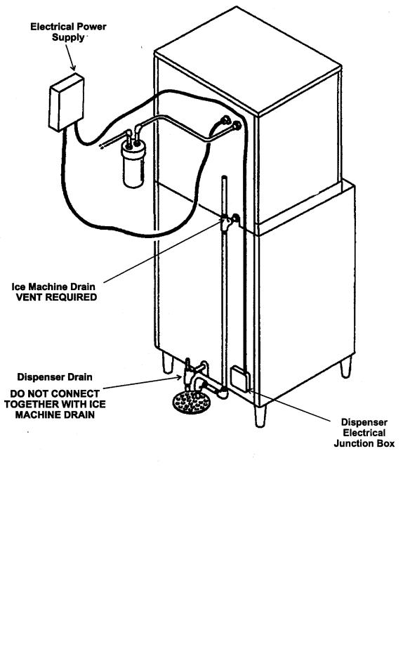
Drain Connections -Follow all applicable codes.
As ice melts in the dispenser, the water must be drained away. It is critical that a proper drain be connected to the dispenser. Remember that this is a gravity drain system, the drain tubing must slope down a minimum of ¼ inch per foot of horizontal run. Usually an air gap must be established between the end of the drain tube and the building’s drain receptacle. The dispenser’s vented drain must be separate from the drain used by the ice machine.
Electrical Connections - Follow all applicable codes.
There is a junction box on the back of the dispenser, connect the power supply to the wires inside the junction box. Be certain that the ice machine and dispenser are grounded.
Page 6
 Loading...