

Page 1

System x3400 M2 Types 7836 and 7837
Installation and User’s Guide
Page 2

Page 3

System x3400 M2 Types 7836 and 7837
Installation and User’s Guide
Page 4

Note:
Before using this information and the product it supports, read the general information in Appendix B, “Notices,” on page 123 and
the IBM Safety Information, IBM Environmental Notices and User's Guide, and the Warranty and Support Information document on
the IBM System x Documentation CD.
Fourth Edition (April 2011)
© Copyright IBM Corporation 2011.
US Government Users Restricted Rights – Use, duplication or disclosure restricted by GSA ADP Schedule Contract
with IBM Corp.
Page 5

Contents
Safety ............................vii
Chapter 1. The System x3400 M2 server ...............1
The IBM System x Documentation CD.................4
Hardware and software requirements ................4
Using the Documentation Browser .................5
Related documentation ......................5
Notices and statements in this document ................6
Features and specifications .....................7
What your server offers ......................9
Reliability, availability, and serviceability ................12
IBM Systems Director ......................13
The UpdateXpress System Packs ..................14
Server controls, LEDs, and power ..................14
Front view .........................14
Rear view ..........................19
Server power features .....................21
Chapter 2. Installing optional devices................23
Server components .......................23
System-board internal connectors .................24
System-board switches and jumpers ................25
System-board external connectors .................29
System-board option connectors .................30
System-board LEDs ......................31
Optional one-slot PCI extender card ................31
Optional two-slot PCI extender card ................32
Installation guidelines ......................32
System reliability guidelines ...................33
Working inside the server with the power on .............34
Handling static-sensitive devices .................34
Removing the left-side cover ....................36
Removing the bezel .......................36
Opening and closing the bezel media door...............38
Opening the power-supply cage ..................40
Closing the power-supply cage ...................41
Removing the air baffle ......................42
Removing the fan cage assembly ..................43
Installing a memory module ....................46
Installing drives .........................52
Installing a DVD drive .....................55
Installing an optional tape drive ..................59
Installing a hot-swap hard disk drive ................63
IDs for hot-swap hard disk drives .................66
Installing a simple-swap SATA hard disk drive ............66
Power and signal cables for internal drives .............69
Installing an adapter .......................70
Installing a second microprocessor .................73
Removing a power supply .....................78
Installing a power supply .....................81
Installing a redundant power supply .................82
Removing a hot-swap fan
Installing a hot-swap fan .....................84
.....................83
© Copyright IBM Corp. 2011 iii
Page 6

Internal cable routing and connectors ................85
Installing the virtual media key ...................96
Completing the installation.....................97
Replacing the bezel ......................97
Replace the air baffle .....................98
Installing the fan cage assembly .................99
Replacing the left-side cover ..................101
Connecting the cables .....................102
Updating the server configuration.................102
Connecting external devices ...................103
Chapter 3. Configuring the server.................105
Using the Setup utility ......................106
Starting the Setup utility ....................106
Setup utility menu choices ...................106
Passwords .........................110
Using the Boot Manager program..................111
Starting the backup server firmware .................111
Using the ServerGuide Setup and Installation CD ............111
ServerGuide features .....................112
Setup and configuration overview.................112
Typical operating-system installation................112
Installing your operating system without using ServerGuide .......113
Using the integrated management module ..............113
Using the remote presence capability and blue-screen capture .......115
Enabling the remote presence feature ...............115
Obtaining the IP address for the IMM ...............115
Logging on to the Web interface .................116
Enabling the Broadcom Gigabit Ethernet Utility program .........116
Configuring the Broadcom Gigabit Ethernet controller ..........117
Using LSI Configuration Utility program ...............117
Starting the LSI Configuration Utility program ............118
Formatting a hard disk drive ..................118
Creating a RAID array of hard disk drives .............119
IBM Advanced Settings Utility program ................119
Updating IBM Systems Director ..................119
The UpdateXpress System Pack Installer...............120
Appendix A. Getting help and technical assistance ..........121
Before you call ........................121
Using the documentation .....................121
Getting help and information from the World Wide Web .........121
Software service and support ...................122
Hardware service and support ...................122
IBM Taiwan product service ....................122
Appendix B. Notices ......................123
Trademarks..........................123
Important notes ........................124
Electronic emission notices ....................125
Federal Communications Commission (FCC) statement ........125
Industry Canada Class A emission compliance statement ........125
Avis de conformité à la réglementation d'Industrie Canada
Australia and New Zealand Class A statement ............125
United Kingdom telecommunications safety requirement ........125
European Union EMC Directive conformance statement ........126
iv System x3400 M2 Types 7836 and 7837: Installation and User’s Guide
.......125
Page 7

Taiwanese Class A warning statement ...............126
Germany Electromagnetic Compatibility Directive ...........126
People's Republic of China Class A warning statement .........127
Taiwan Class A compliance statement ...............127
Japan Electronics and Information Technology Industries Association (JEITA)
statement ........................128
Japanese Voluntary Control Council for Interference (VCCI) statement 128
Korean Class A warning statement ................128
Index ............................129
Contents v
Page 8

vi System x3400 M2 Types 7836 and 7837: Installation and User’s Guide
Page 9
Safety
Before installing this product, read the Safety Information.
Antes de instalar este produto, leia as Informações de Segurança.
Pred instalací tohoto produktu si prectete prírucku bezpecnostních instrukcí.
Læs sikkerhedsforskrifterne, før du installerer dette produkt.
Lees voordat u dit product installeert eerst de veiligheidsvoorschriften.
Ennen kuin asennat tämän tuotteen, lue turvaohjeet kohdasta Safety Information.
Avant d'installer ce produit, lisez les consignes de sécurité.
Vor der Installation dieses Produkts die Sicherheitshinweise lesen.
Prima di installare questo prodotto, leggere le Informazioni sulla Sicurezza.
Les sikkerhetsinformasjonen (Safety Information) før du installerer dette produktet.
Antes de instalar este produto, leia as Informações sobre Segurança.
Antes de instalar este producto, lea la información de seguridad.
Läs säkerhetsinformationen innan du installerar den här produkten.
© Copyright IBM Corp. 2011 vii
Page 10

Important:
All caution and danger statements in this documentation begin with a number. This
number is used to cross reference an English caution or danger statement with
translated versions of the caution or danger statement in the IBM Safety Information
book.
For example, if a caution statement begins with a number 1, translations for that
caution statement appear in the IBM Safety Information book under statement 1.
Be sure to read all caution and danger statements in this documentation before
performing the instructions. Read any additional safety information that comes with
the blade server or optional device before you install the device.
viii System x3400 M2 Types 7836 and 7837: Installation and User’s Guide
Page 11
Statement 1:
DANGER
Electrical current from power, telephone, and communication cables is
hazardous.
To avoid a shock hazard:
v Do not connect or disconnect any cables or perform installation,
maintenance, or reconfiguration of this product during an electrical
storm.
v Connect all power cords to a properly wired and grounded electrical
outlet.
v Connect to properly wired outlets any equipment that will be attached to
this product.
v When possible, use one hand only to connect or disconnect signal
cables.
v Never turn on any equipment when there is evidence of fire, water, or
structural damage.
v Disconnect the attached power cords, telecommunications systems,
networks, and modems before you open the device covers, unless
instructed otherwise in the installation and configuration procedures.
v Connect and disconnect cables as described in the following table when
installing, moving, or opening covers on this product or attached
devices.
To Connect: To Disconnect:
1. Turn everything OFF.
2. First, attach all cables to devices.
3. Attach signal cables to connectors.
4. Attach power cords to outlet.
5. Turn device ON.
1. Turn everything OFF.
2. First, remove power cords from outlet.
3. Remove signal cables from connectors.
4. Remove all cables from devices.
Safety ix
Page 12

Statement 2:
CAUTION:
When replacing the lithium battery, use only IBM Part Number 33F8354 or an
equivalent type battery recommended by the manufacturer. If your system has
a module containing a lithium battery, replace it only with the same module
type made by the same manufacturer. The battery contains lithium and can
explode if not properly used, handled, or disposed of.
Do not:
v Throw or immerse into water
v Heat to more than 100°C (212°F)
v Repair or disassemble
Dispose of the battery as required by local ordinances or regulations.
x System x3400 M2 Types 7836 and 7837: Installation and User’s Guide
Page 13
Statement 3:
CAUTION:
When laser products (such as CD-ROMs, DVD drives, fiber optic devices, or
transmitters) are installed, note the following:
v Do not remove the covers. Removing the covers of the laser product could
result in exposure to hazardous laser radiation. There are no serviceable
parts inside the device.
v Use of controls or adjustments or performance of procedures other than
those specified herein might result in hazardous radiation exposure.
DANGER
Some laser products contain an embedded Class 3A or Class 3B laser
diode. Note the following.
Laser radiation when open. Do not stare into the beam, do not view directly
with optical instruments, and avoid direct exposure to the beam.
Class 1 Laser Product
Laser Klasse 1
Laser Klass 1
Luokan 1 Laserlaite
Appareil A Laser de Classe 1
`
Safety xi
Page 14
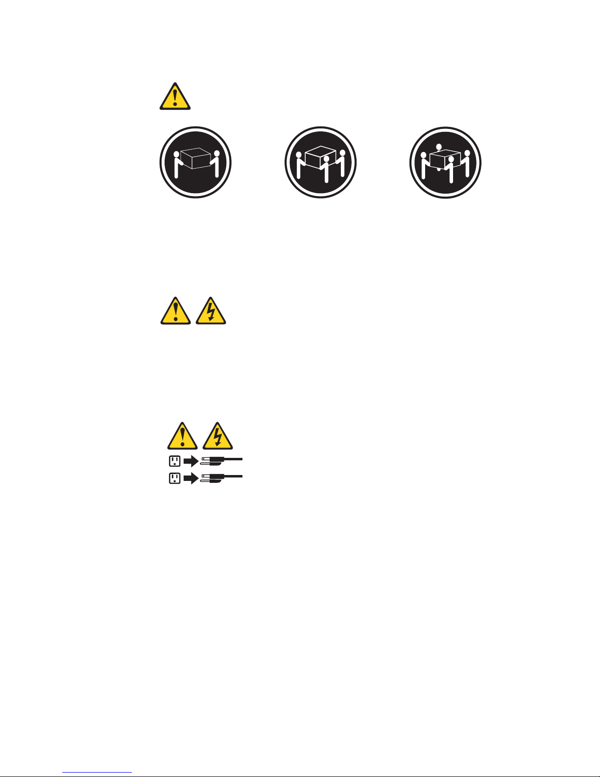
Statement 4:
≥ 18 kg (39.7 lb) ≥ 32 kg (70.5 lb) ≥ 55 kg (121.2 lb)
CAUTION:
Use safe practices when lifting.
Statement 5:
CAUTION:
The power control button on the device and the power switch on the power
supply do not turn off the electrical current supplied to the device. The device
also might have more than one power cord. To remove all electrical current
from the device, ensure that all power cords are disconnected from the power
source.
2
1
xii System x3400 M2 Types 7836 and 7837: Installation and User’s Guide
Page 15
Statement 8:
CAUTION:
Never remove the cover on a power supply or any part that has the following
label attached.
Hazardous voltage, current, and energy levels are present inside any
component that has this label attached. There are no serviceable parts inside
these components. If you suspect a problem with one of these parts, contact
a service technician.
Statement 11:
CAUTION:
The following label indicates sharp edges, corners, or joints nearby.
Statement 12:
CAUTION:
The following label indicates a hot surface nearby.
Safety xiii
Page 16
Statement 13:
DANGER
Overloading a branch circuit is potentially a fire hazard and a shock hazard
under certain conditions. To avoid these hazards, ensure that your system
electrical requirements do not exceed branch circuit protection
requirements. Refer to the information that is provided with your device for
electrical specifications.
Statement 15:
CAUTION:
Make sure that the rack is secured properly to avoid tipping when the server
unit is extended.
Statement 17:
CAUTION:
The following label indicates moving parts nearby.
xiv System x3400 M2 Types 7836 and 7837: Installation and User’s Guide
Page 17
Statement 26:
CAUTION:
Do not place any object on top of rack-mounted devices.
This server is suitable for use on an IT power-distribution system whose maximum
phase-to-phase voltage is 240 V under any distribution fault condition.
Safety xv
Page 18

xvi System x3400 M2 Types 7836 and 7837: Installation and User’s Guide
Page 19

Chapter 1. The System x3400 M2 server
This Installation and User's Guide contains information and instructions for setting
up your IBM System x3400 M2 Types 7836 and 7837 server, instructions for
installing optional devices, and instructions for cabling, and configuring the server.
For removing and installing optional devices, diagnostics and troubleshooting
information, see the Problem Determination and Service Guide on the IBM System
x Documentation CD, which comes with the server.
®
The IBM
server that is based on IBM X-Architecture
server is ideally suited for networking environments that require superior
microprocessor performance, input/output (I/O) flexibility, and manageability.
Performance, ease of use, reliability, and expansion capabilities were key
considerations in the design of the server. These design features make it possible
for you to customize the system hardware to meet your needs today and provide
flexible expansion capabilities for the future.
The server comes with a limited warranty. For information about the terms of the
warranty and getting service and assistance, see the Warranty and Support
Information document on the IBM System x Documentation CD.
The server contains IBM Enterprise X-Architecture technologies, which help
increase performance, reliability, and availability. For more information, see “What
your server offers” on page 9 and “Reliability, availability, and serviceability” on page
12.
System x3400 M2 Types 7836 and 7837 is a 5-U-high, high-performance
®
technologies. This high-performance
You can obtain up-to-date information about the server and other IBM server
products at http://www.ibm.com/systems/x/. At http://www.ibm.com/support/
mysupport/, you can create a personalized support page by identifying IBM
products that are of interest to you. From this personalized page, you can subscribe
to weekly e-mail notifications about new technical documents, search for information
and downloads, and access various administrative services.
If you participate in the IBM client reference program, you can share information
about your use of technology, best practices, and innovative solutions; build a
professional network; and gain visibility for your business. For more information
about the IBM client reference program, see http://www.ibm.com/ibm/
clientreference/.
Some server models support four 3.5-inch simple-swap SATA hard disk drives, or
four 3.5-inch hot-swap SAS or SATA hard disk drives, sixteen or eight 2.5-inch
hot-swap SAS or SATA hard disk drives. The illustrations in this document might
differ slightly from your model.
The following is an illustration of the simple-swap server model.
1. Racks are measured in vertical increments of 1.75 inches each. Each increment is called a "U." A 1-U-high device is 1.75 inches
tall.
© Copyright IBM Corp. 2011
1
Page 20
The following is an illustration of the 3.5-inch hot-swap SAS or SATA server model.
The following is an illustration of the 2.5-inch hot-swap SAS or SATA server model.
2 System x3400 M2 Types 7836 and 7837: Installation and User’s Guide
Page 21
If firmware and documentation updates are available, you can download them from
the IBM Web site. The server might have features that are not described in the
documentation that comes with the server, and the documentation might be updated
occasionally to include information about those features, or technical updates might
be available to provide additional information that is not included in the server
documentation. To check for updates, complete the following steps.
Note: Changes are made periodically to the IBM Web site. Procedures for locating
firmware and documentation might vary slightly from what is described in this
document.
1. Go to http://www.ibm.com/systems/support/.
2. Under Product support, click System x.
3. Under Popular links, click Software and device drivers for firmware updates,
or click Publications lookup for documentation updates.
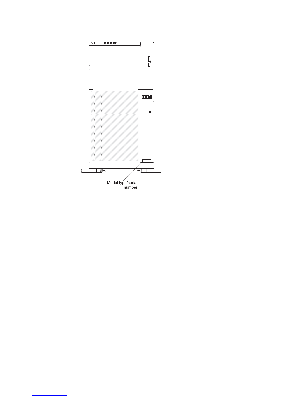
Record information about the server in the following table.
Product name IBM System x3400 M2 server
Machine type 7836 or 7837
Model number _____________________________________________
Serial number _____________________________________________
The model number and serial number are on the lower right side of the bezel, as
shown in the following illustration.
Chapter 1. The System x3400 M2 server 3
Page 22
Note: The illustrations in this document might differ slightly from your hardware.
You can download an IBM ServerGuide Setup and Installation CD to help you
configure the hardware, install device drivers, and install the operating system.
For a list of supported optional devices for the server, see http://www.ibm.com/
servers/eserver/serverproven/compat/us/.
Important: The server keys cannot be duplicated by a locksmith. If you lose them,
order replacement keys from the key manufacturer. The key serial number and the
telephone number of the manufacturer are on a tag that is attached to the keys.
If you plan to install the server in a rack, you must purchase a Tower-to-Rack
conversion kit.
The IBM System x Documentation CD
The IBM System x Documentation CD contains documentation for the server in
Portable Document Format (PDF) and includes the IBM Documentation Browser to
help you find information quickly.
Hardware and software requirements
The IBM System x Documentation CD requires the following minimum hardware
and software:
v Microsoft Windows XP, Windows 2000, or Red Hat Linux
v 100 MHz microprocessor
v 32 MB of RAM
v Adobe Acrobat Reader 3.0 (or later) or xpdf, which comes with Linux operating
systems
4 System x3400 M2 Types 7836 and 7837: Installation and User’s Guide
Page 23

Using the Documentation Browser
Use the Documentation Browser to browse the contents of the CD, read brief
descriptions of the documents, and view documents, using Adobe Acrobat Reader
or xpdf. The Documentation Browser automatically detects the regional settings in
use in your server and displays the documents in the language for that region (if
available). If a document is not available in the language for that region, the
English-language version is displayed.
Use one of the following procedures to start the Documentation Browser:
v If Autostart is enabled, insert the CD into the CD or DVD drive. The
Documentation Browser starts automatically.
v If Autostart is disabled or is not enabled for all users, use one of the following
procedures:
– If you are using a Windows operating system, insert the CD into the CD or
DVD drive and click Start -> Run.IntheOpen field, type
e:\win32.bat
where e is the drive letter of the CD or DVD drive, and click OK.
– If you are using Red Hat Linux, insert the CD into the CD or DVD drive; then,
run the following command from the /mnt/cdrom directory:
sh runlinux.sh
Select the server from the Product menu. The Available Topics list displays all the
documents for the server. Some documents might be in folders. A plus sign (+)
indicates each folder or document that has additional documents under it. Click the
plus sign to display the additional documents.
When you select a document, a description of the document is displayed under
Topic Description. To select more than one document, press and hold the Ctrl key
while you select the documents. Click View Book to view the selected document or
documents in Acrobat Reader or xpdf. If you selected more than one document, all
the selected documents are opened in Acrobat Reader or xpdf.
To search all the documents, type a word or word string in the Search field and
click Search. The documents in which the word or word string appears are listed in
order of the most occurrences. Click a document to view it, and press Crtl+F to use
the Acrobat search function, or press Alt+F to use the xpdf search function within
the document.
Click Help for detailed information about using the Documentation Browser.
Related documentation
This Installation and User’s Guide contains general information about the server
including how to set up and cabling the server, how to install supported optional
devices, and how to configure the server. The following documentation also comes
with the server:
v Warranty and Support Information
This document is in PDF on the IBM System x Documentation CD. It contains
information about the terms of the warranty and getting service and assistance.
v Environmental Notices and User Guide
This document is in PDF format on the IBM System x Documentation CD. It
contains translated environmental notices.
Chapter 1. The System x3400 M2 server 5
Page 24

v Safety Information
This document is in PDF on the IBM System x Documentation CD. It contains
translated caution and danger statements. Each caution and danger statement
that appears in the documentation has a number that you can use to locate the
corresponding statement in your language in the Safety Information document.
v Problem Determination and Service Guide
This document is in PDF on the IBM System x Documentation CD. It contains
information to help you solve problems yourself, and it contains information for
service technicians.
Depending on the server model, additional documentation might be included on the
IBM System x Documentation CD.
™
The xSeries and System x
Tools Center is an online information center that
contains information about tools for updating, managing, and deploying firmware,
device drivers, and operating systems. The System x and xSeries Tools Center is at
http://publib.boulder.ibm.com/infocenter/toolsctr/v1r0/index.jsp.
The server might have features that are not described in the documentation that
you received with the server. The documentation might be updated occasionally to
include information about those features, or technical updates might be available to
provide additional information that is not included in the server documentation.
These updates are available from the IBM Web site. To check for updated
documentation and technical updates, complete the following steps.
Note: Changes are made periodically to the IBM Web site. The actual procedure
might vary slightly from what is described in this document.
1. Go to http://www.ibm.com/systems/support/.
2. Under Product support, click System x.
3. Under Popular links, click Publications lookup.
4. From the Product family menu, select System x3400 M2 and click Continue.
Notices and statements in this document
The caution and danger statements in this document are also in the multilingual
Safety Information document, which is on the IBM System x Documentation CD.
Each statement is numbered for reference to the corresponding statement in your
language in the Safety Information document.
The following notices and statements are used in this document:
v Note: These notices provide important tips, guidance, or advice.
v Important: These notices provide information or advice that might help you avoid
inconvenient or problem situations.
v Attention: These notices indicate potential damage to programs, devices, or
data. An attention notice is placed just before the instruction or situation in which
damage might occur.
v Caution: These statements indicate situations that can be potentially hazardous
to you. A caution statement is placed just before the description of a potentially
hazardous procedure step or situation.
v Danger: These statements indicate situations that can be potentially lethal or
extremely hazardous to you. A danger statement is placed just before the
description of a potentially lethal or extremely hazardous procedure step or
situation.
6 System x3400 M2 Types 7836 and 7837: Installation and User’s Guide
Page 25
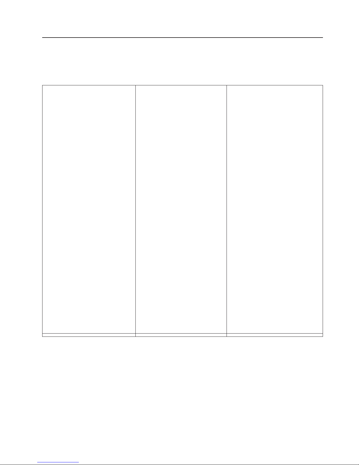
Features and specifications
The following information is a summary of the features and specifications for
Machine Types 7836 and 7837. Depending on the server model, some features
might not be available, or some specifications might not apply.
Table 1. Features and specifications
Microprocessor:
v Supports up to two Intel Pentium
dual-core or quad-core microprocessors
(one installed) with integrated memory
controller and QuickPath Interconnect
(QPI) architecture. The second
microprocessor comes with a pluggable
VRM
v Designed for LGA 1366 socket
v Scalable up to four cores
v 32 KB instruction cache, 32 KB data
cache, and 8 MB cache that is shared
among the cores
v Support for Intel Extended Memory 64
Technology (EM64T)
Note:
v Use the Setup utility to determine the
type and speed of the microprocessors.
v For a list of supported microprocessors,
see http://www.ibm.com/servers/eserver/
serverproven/compat/us/.
Memory:
v Minimum: 1GB
v Maximum: 96 GB (48 GB in mirrored
mode)
– 24 GB using unbuffered DIMMs
(UDIMMs)
– 96 GB using registered DIMMs
(RDIMMs)
v Types: PC3-10600R-900 (single-rank or
dual-rank, 800, 1066, and 1333 MHz,
ECC, DDR3 registered SDRAM DIMMs
only
v RDIMMssizes:1GB,2GB,4GBand
8 GB single-rank, dual-rank or quad
rank
v UDIMMs sizes: 1 GB and 2 GB
single-rank or dual-rank
Fans:
Three speed-controlled hot-swap fans
Power supply:
One 670 watt (100 - 240 V ac)
Two 920-watt
Size:
v Height: 440 mm (17.3 in.)
v Depth: 767 mm (30.2 in.)
v Width: 218 mm (8.6 in.)
v Weight:20kg(42lb)to34kg(75lb)
depending upon configuration
RAID controllers:
v A ServeRAID-BR10i SAS/SATA
adapter that provides RAID levels 0, 1,
and 1E (comes standard on some
hot-swap SAS and hot-swap SATA
models).
v An optional ServeRAID-MR10i
SAS/SATA adapter that provides RAID
levels 0, 1, 5, 6, 10, 50, and 60 can
also be ordered.
v An optional ServeRAID-MR10is
SAS/SATA adapter that provides RAID
levels 0, 1, 5, 6, 10, 50, and 60 can
also be ordered.
Drives (depending on the model):
v Optical drives: SATA
v Hard disk drives: SAS and SATA
Drive bays (depending on the model):
v Three 5.25-in. bays (one half-high
DVD-ROM drive installed). Optionally you
can install one full-high or two half-high
internal tape drives in bays 2 and 3.
v One of the following:
– Four 3.5-inch simple-swap SATA
drives
– Four 3.5-inch hot-swap SAS or SATA
drives
– Sixteen or eight 2.5-inch hot-swap
SAS or SATA drives
Integrated functions:
v Integrated Management Module (IMM),
which provides service processor control
and monitoring functions, video controller,
and (when the optional virtual media key
is installed) remote keyboard, video,
mouse, and remote hard disk drive
capabilities
v Broadcom BCM5709 Gb Ethernet
controller with TCP/IP Offload Engine
(TOE) and Wake on LAN support
v Onboard SATA controller (simple-swap
models)
v Seven Universal Serial Bus (USB) 2.0
ports (two front and four rear of the
chassis), and one for the internal USB
tape drive.
v Two Ethernet ports
v One System Management RJ-45 on the
rear to connect to a systems
management network. This system
management connector is dedicated to
the IMM functions. This connector is
active with or without the optional IBM
Virtual Media Key installed.
v One serial port
Six SATA ports (four through the iPASS
v
connector for simple-swap drives and two
for the optical drives)
Chapter 1. The System x3400 M2 server
7
Page 26
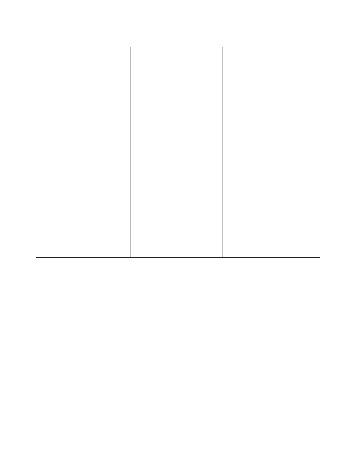
Table 1. Features and specifications (continued)
Acoustical noise emissions:
v Sound power, idling: 5.5 bel
v Sound power, operating: 6.0 bel
Environment:
v Air temperature:
– Server on: 10° to 35°C (50° to 95°F)
Altitude: 0 to 915 m (3000 ft)
– Server on: 10° to 32°C (50° to 90°F)
Altitude: 0 to 915 m (3000 ft) to 2134
m (7000 ft)
– Server on: 10° to 28°C (50° to 83°F)
Altitude: 2134 m (7000 ft) to 3050 m
(10000 ft)
– Server off: 5° to 45°C (41.0° to
113°F)
– Shipping: -40° to 60°C (-40° to
140°F)
v Humidity (operating and storage):
– Server on: 20% to 80%, Maximum
dew point 21°C, Maximum rate of
change 5°C/hr.
– Server off: 8% to 80%, Maximum
dew point 27°C
Heat output:
Approximate heat output in British thermal
units (Btu) per hour:
v Minimum configuration: 693 Btu per
hour (203 watts)
v Maximum configuration: 2788 Btu per
hour (817 watts)
Up to eight expansion slots
(depending on the model):
v Six expansion slots on the system
board
– Four PCI Express Gen2 x8 slots
(two x8 links and two x4 link)
– One PCI Express Gen2 x16 slot
(x8 link)
– One PCI 32-bit/33 MHz slot
v One PCI Express Gen1 x8 (x4) slot on
the one-slot extender card
v Two PCI-X 32-bit/64-bit 133/100/66/
MHz slots on the two-slot extender
card
Video controller:
v Matrox G200eV video on system
board
v Compatible with SVGA and VGA
Diagnostic LEDs:
v Fan
v Microprocessor
v Memory
v Power supply
v Voltage regulator module (VRM)
v PCI
v Battery
v IMM heartbeat
v Enclosure manager heartbeat
Electrical input:
v Sine-wave input (50 or 60 Hz) required
v Input voltage and frequency ranges
automatically selected
v Input voltage low range:
– Minimum: 100 V ac
– Maximum: 127 V ac
v Input voltage high range:
– Minimum: 200 V ac
– Maximum: 240 V ac
v Input kilovolt-amperes (kVA)
approximately:
– Minimum: 0.21 kVA (all models)
– Maximum: 0.82 kVA
Notes:
1. Power consumption and heat output
vary depending on the number and type
of optional features installed and the
power-management optional features in
use.
2. These levels were measured in
controlled acoustical environments
according to the procedures specified
by the American National Standards
Institute (ANSI) S12.10 and ISO 7779
and are reported in accordance with
ISO 9296. Actual sound-pressure levels
in a given location might exceed the
average values stated because of room
reflections and other nearby noise
sources. The declared sound-power
levels indicate an upper limit, below
which a large number of computers will
operate.
8 System x3400 M2 Types 7836 and 7837: Installation and User’s Guide
Page 27

What your server offers
The server uses the following features and technologies:
v Integrated Management Module
The Integrated Management module (IMM) combines service processor
functions, video controller, and (when an optional virtual media key is installed)
remote presence function in a single chip. The IMM provides advanced
service-processor control, monitoring, and alerting function. If an environmental
condition exceeds a threshold or if a system component fails, the IMM lights
LEDs to help you diagnose the problem, records the error in the event log, and
alerts you to the problem. Optionally, the IMM also provides a virtual presence
capability for remote server management capabilities. The IMM provides remote
server management through the following industry-standard interfaces:
– Intelligent Platform Management Interface (IPMI) version 2.0
– Simple Network Management Protocol (SNMP) version 3
– Common Information Model (CIM)
– Web browser
For additional information, see “Using the integrated management module” on
page 113.
v UEFI-compliant server firmware
The IBM System x Server Firmware offers several features, including Unified
Extensible Firmware Interface (UEFI) version 2.1 compliance, Active Energy
Management (AEM) technology, enhanced reliability, availability, and
serviceability (RAS) capabilities, and basic input/output system (BIOS)
compatibility support. UEFI replaces the legacy BIOS. UEFI defines a standard
interface between the operating system, platform firmware and external devices,
and offers capabilities that far exceeds that of the legacy BIOS.
The server design combines the UEFI capabilities and features with legacy BIOS
compatibility. The server is capable of booting UEFI-compliant operating systems,
BIOS-based operating systems, and BIOS-based adapters as well as
UEFI-compliant adapters.
Note: The server does not support DOS (Disk Operating System).
v IBM Dynamic System Analysis Preboot diagnostics programs
The Dynamic System Analysis (DSA) Preboot diagnostics programs are stored
on the integrated USB memory. It collects and analyzes system information to aid
in diagnosing server problems. The diagnostic programs collect the following
information about the server:
– System configuration
– Network interfaces and settings
– Installed hardware
– Light path diagnostics status
– Service processor status and configuration
– Vital product data, firmware, and UEFI (formerly BIOS) configuration
– Hard disk drive health
– RAID controller configuration
– Event logs for ServeRAID controllers and service processors
The DSA program creates a chronologically ordered merge of the system-event
log (as the IPMI event log), the IMM event log (as the ASM event log), and the
operating system logs. The information is collected into a file that you can send
Chapter 1. The System x3400 M2 server 9
Page 28

to IBM service and support. Additionally, you can view the information locally
through a generated text report file. You can also copy the log to a removable
media and view the log from a Web browser.
For additional information about DSA Preboot diagnostics, see the Problem
Determination and Service Guide on the IBM System x Documentation CD
v High-performance graphics controller
The server comes with an onboard high-performance graphics controller that
supports high resolutions and includes many performance-enhancing features for
the operating-system environment.
v IBM Systems Director CD
IBM Systems Director is a workgroup-hardware-management tool that you can
use to centrally manage System x and xSeries servers. For more information,
see the IBM Systems Director documentation on the IBM Systems Director CD
and “IBM Systems Director” on page 13.
v IBM Enterprise X-Architecture technology
IBM X-Architecture technology combines proven, innovative IBM designs to make
your Intel-processor-based server powerful, scalable, and reliable. For more
information, see http://www.ibm.com/servers/eserver/xseries/xarchitecture/
enterprise/index.html.
v IBM ServerGuide Setup and Installation CD
The ServerGuide Setup and Installation CD, which you can download from the
Web, provides programs to help you set up the server and install a Windows
operating system. The ServerGuide program detects installed optional hardware
devices and provides the correct configuration programs and device drivers. For
more information about the ServerGuide Setup and Installation CD, see “Using
the ServerGuide Setup and Installation CD” on page 111.
v Active Energy Manager
The IBM Active Energy Manager solution is an IBM Systems Director plug-in that
measures and reports server power consumption as it occurs. This enables you
to monitor power consumption in correlation to specific software application
programs and hardware configurations. You can obtain the measurement values
through the systems-management interface and view them, using IBM Systems
Director. For more information, including the required levels of IBM Systems
Director and Active Energy Manager, see the IBM Systems Director
documentation on the IBM Systems Director CD, or see http://www.ibm.com/
servers/systems/management/director/resources/.
v Integrated network support
The server comes with an integrated dual-port Broadcom Gigabit Ethernet
controller, which supports connection to a 10 Mbps, 100 Mbps, or 1000 Mbps
network. For more information, see “Configuring the Broadcom Gigabit Ethernet
controller” on page 117.
v Integrated Trusted Platform Module (TPM)
This integrated security chip performs cryptographic functions and stores private
and public secure keys. It provides the hardware support for the Trusted
Computing Group (TCG) specification. You can download the software to support
the TCG specification, when the software is available. See http://www.ibm.com/
servers/eserver/xseries/scalable_family.html for details about the TPM
implementation. You can enable TPM support through the Setup utility under the
System Security menu option.
v Large data-storage capacity and hot-swap capabilities
Some hot-swap server models support eight or sixteen (depending on your
model) slim-high, 2.5-inch hot-swap hard disk drives or four 3.5-inch hot-swap
10 System x3400 M2 Types 7836 and 7837: Installation and User’s Guide
Page 29

hard disk drives (depending on the model). With the hot-swap feature, you can
add, remove, or replace hard disk drives without turning off the server.
v Large system-memory capacity
The server supports up to 96 GB (reduced to 48 GB in mirroring mode) of
system memory. The memory controller supports error correcting code (ECC) for
up to 12 industry-standard PC3-10600R-999 (single-rank or dual-rank), 800,
1067, and 1333 MHz, DDR3 (third-generation double-data-rate), registered,
synchronous dynamic random access memory (SDRAM) dual inline memory
modules (DIMMs).
v Memory mirroring
Some models support memory mirroring. Memory mirroring replicates and stores
data on two pairs of DIMMs within two channels (channel 0 and 1)
simultaneously. If a failure occurs, the memory controller switches from the
primary pair of memory DIMMs to the backup pair of DIMMs. To support memory
mirroring, you must install a pair of DIMMs at a time. One DIMM must be in
channel 0, and the mirroring DIMM must be in the same slot in channel 1. For
more information, see memory mirroring on page 47.
v ServeRAID support
The ServeRAID adapter provides hardware redundant array of independent disks
(RAID) support to create configurations. The standard RAID adapter provides
RAID levels 0, 1, and 1E. The optional RAID adapters are available for purchase
and provide RAID levels 0, 1, 5, 6, 10, 50, and 60. See “Installing an adapter” on
page 70 and “Using LSI Configuration Utility program” on page 117 for more
information about the adapters that are supported and creating RAID arrays.
v Symmetric multiprocessing (SMP)
The server supports up to two Intel Xeon microprocessors. Each microprocessor
provides symmetric multiprocessing capability. When you install the second
microprocessor, this will enhance the performance of the server.
v Systems-management capabilities
The server comes with an integrated management module (IMM). When the IMM
is used with the systems-management software that comes with the server, you
can manage the functions of the server locally and remotely. The IMM also
provides system monitoring, event recording, and network alert capability. The
systems-management connector on the rear of the server is dedicated to the
IMM. The dedicated systems-management connector provides additional security
by physically separating the management network traffic from the production
network. You can use the Setup utility to configure the server to use a dedicated
systems-management network or a shared network.
v TCP/IP offload engine (TOE) support
The Ethernet controller in the server supports TOE, which is a technology that
offloads the TCP/IP flow from the microprocessor and I/O subsystem to increase
the speed of the TCP/IP flow. When an operating system that supports TOE is
running on the server and TOE is enabled, the server supports TOE operation.
See the operating-system documentation for information about enabling TOE.
The Windows operating system requires that the Windows Scalable Network
Pack (SNP) be installed for TOE support.
Note: As of the date of this document, the Linux operating system does not
support TOE.
Chapter 1. The System x3400 M2 server 11
Page 30

Reliability, availability, and serviceability
Three important server design features are reliability, availability, and serviceability
(RAS). The RAS features help to ensure the integrity of the data that is stored in
the server, the availability of the server when you need it, and the ease with which
you can diagnose and repair problems.
The server might have the following RAS features (the features vary depending on
your model):
v 1-year parts and 1-year labor limited warranty for machine type 7836 and 3-year
parts and 3-year labor limited warranty for machine type 7837.
v Advanced Configuration and Power Interface (ACPI)
v Advanced Desktop Management Interface (DMI) features
v Automatic error retry or recovery
v Automatic memory downsizing on error detection
v Automatic restart on nonmaskable interrupt (NMI)
v Automatic Server Restart (ASR) logic supporting a system restart when the
operating system becomes unresponsive
v Automatic server restart after a power failure, based on the UEFI setting
v Availability of microcode level
v Boot-block recovery
v Built-in, menu-driven setup, system configuration, and redundant array of
independent disks (RAID) configuration
v Built-in monitoring for fan, power, temperature, and voltage
v Cooling fans with speed-sensing capability
v Customer support center that is available 24 hours a day, 7 days a week
v Diagnostic support of ServeRAID adapters
v Error codes and messages
v Error correcting code (ECC) double-data-rate 3 (DDR3) synchronous dynamic
random-access memory (SDRAM) with serial presence detect (SPD)
v Error logging of POST failures
v Hot-swap Serial Attached SCSI (SAS) and hot-swap Serial ATA (SATA) hard disk
drives
v Integrated Ethernet controller
v Key-lock support for physical security
v Memory change messages posted to the error log
v Integrated management module (IMM)
v Power management
v Power-on self-test (POST)
v Read-only memory (ROM) checksums
v ROM-based diagnostic programs
v Simple-swap Serial Advanced Technology Attachment (SATA) hard disk drives
v Standby voltage for system-management features and monitoring
v System auto-configuring from the configuration menu
v System-error LED on the front bezel and diagnostic LEDs on the system board
2
2. Service availability will vary by country. Response time varies; may exclude holidays.
12 System x3400 M2 Types 7836 and 7837: Installation and User’s Guide
Page 31

v Upgradeable integrated management module (IMM) firmware
v Upgradeable microcode for POST, server firmware, and read-only memory
(ROM) resident code, locally or over a LAN
v Vital product data (VPD); includes serial-number information and replacement
part numbers, stored in nonvolatile memory, for easier remote maintenance
v Wake on LAN capability
IBM Systems Director
IBM Systems Director is a platform-management foundation that streamlines the
way you manage physical and virtual systems supports multiple operating systems
and virtualization technologies in IBM and non-IBM x86 platforms.
Through a single user interface, IBM Systems Director provides consistent views for
viewing managed systems, determining how these systems relate to one other, and
identifying their statuses, helping to correlate technical resources with business
needs. A set of common tasks that are included with IBM Systems Director provides
many of the core capabilities that are required for basic management, which means
instant out-of-the-box business value. The common tasks include the following:
v Discovery
v Inventory
v Configuration
v System health
v Monitoring
v Updates
v Event notification
v Automation for managed systems
The IBM Systems Director Web and command-line interfaces provide a consistent
interface that is focused on driving these common tasks and capabilities:
v Discovering, navigating, and visualizing systems on the network with the detailed
inventory and relationships to the other network resources
v Notifying users of problems that occur on systems and the ability to isolate the
sources of the problems
v Notifying users when systems need updates and distributing and installing
updates on a schedule
v Analyzing real-time data for systems and setting critical thresholds that notify the
administrator of emerging problems
v Configuring settings of a single system and creating a configuration plan that can
apply those settings to multiple systems
v Updating installed plug-ins to add new features and functions to the base
capabilities
v Managing the life cycles of virtual resources
For more information about IBM Systems Director, see the documentation on the
IBM Systems Director CD that comes with the server and the IBM xSeries Systems
Management Web page at http://www.ibm.com/systems/management/, which
presents an overview of IBM Systems Management and IBM Systems Director.
Chapter 1. The System x3400 M2 server 13
Page 32

The UpdateXpress System Packs
The UpdateXpress System Packs provide and effective and simple way to update
device drivers, server firmware, and firmware of supported options contained within
the server, for System x and IBM BladeCenter
System Pack contains all the online driver and firmware updates for a specific
machine type and operating system combination. Use the UpdateXpress System
Pack Installer to install the current UpdateXpress System Pack for your server. You
can download the installer and the latest UpdateXpress System Pack for your
server from the Web at no additional cost. To download the installer or the latest
UpdateXpress System Pack, go to http://www.ibm.com/systems/support/
supportsite.wss/docdisplay?lndocid=SERV-XPRESS&brandind=5000008 or
complete the following steps.
Note: Changes are made periodically to the IBM Web site. The actual procedure
might vary slightly from what is described in this document.
1. Go to http://www.ibm.com/systems/support/.
2. Under Product support, click System x.
3. Under Popular links, click Software and device drivers.
4. Under Related downloads, click UpdateXpress.
Server controls, LEDs, and power
This section describes the controls, light-emitting diodes (LEDs), and connectors on
the front and rear of the server, and how to turn the server on and off. For the
location of the LEDs on the system board, see “System-board LEDs” on page 31.
®
servers. Each UpdateXpress
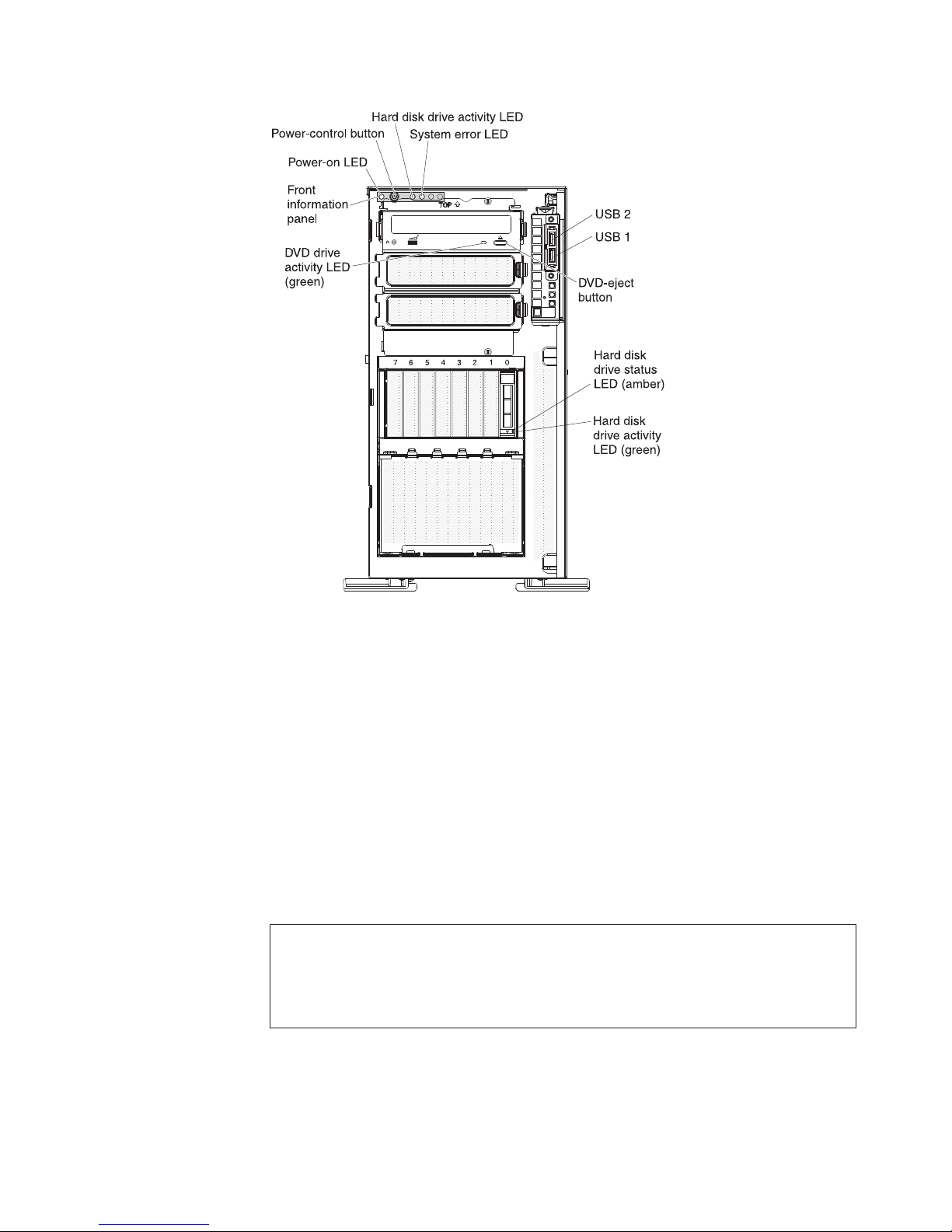
Front view
Note: The illustrations in this document might differ slightly from your model.
The following illustrations show the controls, LEDs, and connectors on the front of
the server models.
14 System x3400 M2 Types 7836 and 7837: Installation and User’s Guide
Page 33

The following illustration shows the 3.5-inch SAS/SATA hot-swap hard disk drive
model.
Chapter 1. The System x3400 M2 server 15
Page 34

The following illustration shows the 2.5-inch SAS/SATA hot-swap hard disk drive
model.
16 System x3400 M2 Types 7836 and 7837: Installation and User’s Guide
Page 35

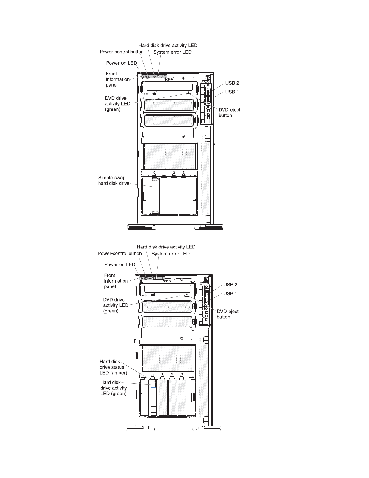
The following illustration shows the 3.5-inch SATA simple-swap hard disk drive
model.
Power-control button and power-on LED
Press this button to turn the server on and off manually or to wake the
server from a reduced-power state. The states of the power-on LED are as
follows:
Off: AC power is not present, or the power supply or the LED itself has
failed.
Flashing rapidly (4 times per second): The server is turned off and is
not ready to be turned on. The power-control button is disabled.
Approximately 1 to 3 minutes after the server is connected to ac power,
the power-control becomes active.
Flashing slowly (once per second): The server is turned off and is
ready to be turned on. You can press the power-control button to turn on
the server.
Lit: The server is turned on.
Fading on and off: The server is in a reduced-power state. To wake the
server, press the power-control button or use the IMM Web interface.
See “Logging on to the Web interface” on page 116 for information on
logging on to the IMM Web interface.
Hard disk drive activity LED
When this LED is flashing rapidly, it indicates that a hard disk drive is in
use.
System-error LED
When this amber LED is lit, it indicates that a system error has occurred.
Chapter 1. The System x3400 M2 server 17
Page 36

An LED on the system board might also be lit to help isolate the error.
Detailed troubleshooting information is in the Problem Determination and
Service Guide on the IBM System x Documentation CD.
USB connectors
Connect USB devices to these connectors.
DVD-eject button
Press this button to release a CD or DVD from the DVD drive.
DVD drive activity LED
When this LED is lit, it indicates that the DVD drive is in use.
Hot-swap hard disk drive activity LED (some models)
On some server models, each hot-swap drive has a hard disk drive activity
LED. When this green LED is flashing, it indicates that the associated hard
disk drive is in use.
When the drive is removed, this LED also is visible on the SAS/SATA
backplane, next to the drive connector. The backplane is the printed circuit
board behind drive bays 4 through 7 on 3.5-inch hard disk drive models and
bays 4 through 19 on 2.5-inch hard disk drive models.
Hot-swap hard disk drive status LED (some models)
On some server models, each hot-swap hard disk drive has an amber
status LED. If this amber status LED is lit, it indicates that the associated
hard disk drive has failed.
If an optional ServeRAID adapter is installed in the server and the LED
flashes slowly (one flash per second), the drive is being rebuilt. If the LED
flashes rapidly (three flashes per second), the adapter is identifying the
drive.
When the drive is removed, this LED also is visible on the SAS/SATA
backplane, below the hot-swap hard disk drive activity LED.
18 System x3400 M2 Types 7836 and 7837: Installation and User’s Guide
Page 37

Rear view
AC power LED
DC power LED
Fault (error) LED
Serial 1
(COM 1)
Video
System
management
Ethernet
connector
NMI button
Ethernet 1
10/100/1000
USB 1
USB 2
USB 3
USB 4
Ethernet 2
10/100/1000
The following illustration shows the LEDs and connectors on the rear of the server,
depending on your server model.
Power cord
connector
Ethernet
transmit/receive
activity LED
Ethernet link
status LED
Ethernet
transmit/receive
activity LED
Ethernet link
status LED
Figure 1. Fixed power supply
Chapter 1. The System x3400 M2 server 19
Page 38

AC power LED
Video
Serial 1
(COM 1)
Systems
management
NMI button
USB 1
USB 2
USB 3
USB 4
Power error LED
DC power LED
Power cord
connector
Ethernet 10/100/1000
Ethernet
transmit/receive
activity LEDs
Ethernet link
status LEDs
Figure 2. Redundant power supply
Power-cord connector
AC power LED
DC power LED
Power-error (Fault) LED
Video connector
Connect the power cord to this connector.
This green LED provides status information about the power supply. During
typical operation, both the ac and dc power LEDs are lit. For any other
combination of LEDs, see the Problem Determination and Service Guide on
the IBM System x Documentation CD.
This green LED provides status information about the power supply. During
typical operation, both the ac and dc power LEDs are lit. For any other
combination of LEDs, see the Problem Determination and Service Guide on
the IBM System x Documentation CD.
When this amber LED is lit, it indicates that the power supply has failed.
For any other combination of LEDs, see the Problem Determination and
Service Guide on the IBM System x Documentation CD
Connect a monitor to this connector.
Note: The maximum video resolution is 1600 x 1200 at 85 Hz.
Serial connector
Connect a 9-pin serial device to this connector.
20 System x3400 M2 Types 7836 and 7837: Installation and User’s Guide
Page 39

Systems-mamagement Ethernet connector
Use this connector to manage the server, using a dedicated management
network. If you use this connector, the IMM cannot be accessed directly
from a production network. A dedicated management network provides
additional security by physically separating the management network traffic
from the production network. You can use the Setup utility to configure the
server to use a dedicated systems management network or a shared
network ( see “Using the Setup utility” on page 106).
USB connectors
Connect USB devices to these connectors.
Ethernet connectors
Use these connectors to connect the server to a network.
Ethernet transmit/receive activity LED
This LED is on the Ethernet connector on the rear of the server. When this
LED is lit, it indicates that there is activity between the server and the
network.
Ethernet link status LED
This LED is on the Ethernet connector on the rear of the server. When this
LED is lit, it indicates that there is an active connection on the Ethernet
port.
Server power features
When the server is connected to an ac power source but is not turned on, the
operating system does not run, and all core logic except for the service processor
(the Integrated Management Module) is shut down; however, the server can
respond to requests to the service processor, such as a remote request to turn on
the server. The power-on LED flashes to indicate that the server is connected to ac
power but is not turned on.
Turning on the server
Approximately 5 seconds after the server is connected to ac power, one or more
fans might start running to provide cooling while the server is connected to power
and the power-on button LED flashes rapidly. Approximately 1 to 3 minutes after the
server is connected to ac power, the power-control button becomes active (the
power-on LED flashes slowly). You can turn on the server by pressing the
power-control button.
The server can also be turned on in any of the following ways:
v If a power failure occurs while the server is turned on, the server will restart
automatically when power is restored.
v If your operating system supports the Wake on LAN feature, the Wake on LAN
feature can turn on the server.
Note: When 4 GB or more of memory (physical or logical) is installed, some
memory is reserved for various system resources and is unavailable to the
operating system. The amount of memory that is reserved for system resources
depends on the operating system, the configuration of the server, and the
configured peripheral component interconnect (PCI) options.
Chapter 1. The System x3400 M2 server 21
Page 40

Turning off the server
When you turn off the server and leave it connected to ac power, the server can
respond to requests to the service processor, such as a remote request to turn on
the server. While the server remains connected to ac power, one or more fans
might continue to run. To remove all power from the server, you must disconnect it
from the power source.
Some operating systems require an orderly shutdown before you turn off the server.
See your operating-system documentation for information about shutting down the
operating system.
Statement 5:
CAUTION:
The power control button on the device and the power switch on the power
supply do not turn off the electrical current supplied to the device. The device
also might have more than one power cord. To remove all electrical current
from the device, ensure that all power cords are disconnected from the power
source.
2
1
The server can be turned off in any of the following ways:
v You can turn off the server from the operating system, if your operating system
supports this feature. After an orderly shutdown of the operating system, the
server will be turned off automatically.
v You can press the power-control button to start an orderly shutdown of the
operating system and turn off the server, if your operating system supports this
feature.
v If the operating system stops functioning, you can press and hold the
power-control button for more than 4 seconds to turn off the server.
v The server can be turned off by Wake on LAN feature.
v The integrated management module (IMM) can turn off the server as an
automatic response to a critical system failure.
22 System x3400 M2 Types 7836 and 7837: Installation and User’s Guide
Page 41

Chapter 2. Installing optional devices
Important: Before you install optional hardware, make sure that the server is
working correctly. Start the server, and make sure that the operating system starts,
if an operating system is installed. If the server is not working correctly, see the
Problem Determination and Service Guide for diagnostic information.
This chapter provides detailed instructions for installing optional hardware devices in
the server.
Server components
The following illustration shows the major components in the server (depending on
the server model). The illustrations in this document might differ slightly from your
hardware.
© Copyright IBM Corp. 2011 23
Page 42

System-board internal connectors
The following illustration shows the internal connectors on the system board.
24 System x3400 M2 Types 7836 and 7837: Installation and User’s Guide
Page 43

System-board switches and jumpers
The following illustration shows the switches and jumpers on the system board.
The following table describes the jumpers on the system board.
Table 2. System board jumpers
Jumper number Jumper name Jumper setting
JP1 Clear CMOS jumper
Chapter 2. Installing optional devices 25
v Pins 1 and 2: Normal
(default) - This keeps the
CMOS data.
v Pins 2 and 3: This clears
the CMOS data, which
clears the power-on
password and
administrator password.
Attention: If you set an
administrator password
and then forget it, there is
no way to change,
override, or remove it. You
must replace the system
board.
Page 44

Table 2. System board jumpers (continued)
Jumper number Jumper name Jumper setting
JP6 UEFI boot recovery jumper
Notes:
v If no jumper is present, the server responds as if the pins are set to 1 and 2.
v Changing the position of the UEFI boot recovery jumper from pins 1 and 2 to pins 2 and
3 before the server is turned on alters which flash ROM page is loaded. Do not change
the jumper pin position after the server is turned on. This can cause an unpredictable
problem.
v Pins 1 and 2: Normal
(default) - Loads the
primary server firmware
ROM.
v Pins 2 and 3: This enables
the server to recovery if
the server firmware
becomes damaged.
The following table describes the function of each pin on the SW6 switch block.
Table 3. System board switches
Switch pin number Default value Description
1 Off Reserved.
2 Off Power-on password override.
Changing the position of this
switch bypasses the
power-on password check
the next time the server is
turned on and starts the
Setup utility so that you can
change or delete the
power-on password. You do
not have to move the switch
back to the default position
after the power-on password
is overridden.
3 Off Reserved.
26 System x3400 M2 Types 7836 and 7837: Installation and User’s Guide
Changing the position of this
switch does not affect the
administrator password check
if an administrator password
is set.
Attention: If you set an
administrator password and
then forget it, there is no way
to change, override, or
remove it. You must replace
the system board.
See “Passwords” on page
110 for additional information
about passwords.
Page 45
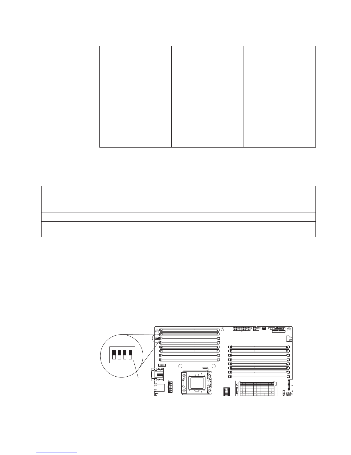
Table 3. System board switches (continued)
Switch pin number Default value Description
4Off
v When this switch is on Off,
this is normal mode. This
loads the primary IMM
firmware ROM page.
v When this switch is
toggled to On, this loads
the secondary (backup)
IMM firmware ROM page.
See the Problem
Determination and Service
Guide for information about
recovering from a firmware
update failure.
The following illustration shows the SW5 switch and the jumpers on the system
board. See the tables below the illustration for information about the switch settings.
Table 4. System-board switch 5
SW 6 Switches Switch description
1 Reserved (default off)
2 Reserved (default off)
3 Reserved (default off)
4 When this switch is off, TPM physical present is de-asserted (default off). When this switch is on,
TPM physical present is asserted.
Important:
1. Before you change any switch settings or move any jumpers, turn off the server,
then, disconnect all power cords and external cables. Review the information in
“Installation guidelines” on page 32, “Handling static-sensitive devices” on page
34, and “Turning off the server” on page 22.
2. Any system-board switch blocks or jumpers that are not shown in the
illustrations in this document are reserved.
The following illustration shows the SW 5 switch and the jumpers on the system
board. See the tables below the illustration for information about the switch settings.
OFF
4 3 2 1
Sw5
switch
block
Chapter 2. Installing optional devices 27
Page 46

Table 5. System-board switch 5
SW 5 Switches Switch description
1 Reserved (default off)
2 Reserved (default off)
3 Reserved (default off)
4 When this switch is off, TPM physical present is de-asserted (default off). When this switch is on,
TPM physical present is asserted.
Notes:
1. Before you change any switch settings or move any jumpers, turn off the server;
then, disconnect all power cords and external cables. (Review the information in
vii and “Installation guidelines” on page 32)
2. Any system-board switch or jumper blocks that are not shown in the illustrations
in this document are reserved.
28 System x3400 M2 Types 7836 and 7837: Installation and User’s Guide
Page 47
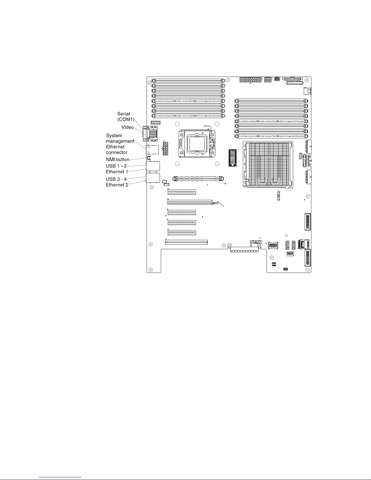
System-board external connectors
The following illustration shows the external input/output (I/O) connectors on the
system board.
Chapter 2. Installing optional devices 29
Page 48

System-board option connectors
The following illustration shows the system-board connectors for user-installable
optional devices.
30 System x3400 M2 Types 7836 and 7837: Installation and User’s Guide
Page 49

System-board LEDs
The following illustration shows the light-emitting diodes (LEDs) on the system
board.
For more information about the system-board LEDs, see the Problem Determination
and Service Guide on the IBM System x Documentation CD.
Optional one-slot PCI extender card
The following is an illustration of the one-slot PCI extender card that you can install
to add an additional PCI slot to the server.
Chapter 2. Installing optional devices 31
Page 50

Optional two-slot PCI extender card
The following is an illustration of the two-slot PCI extender card that you can install
to add two additional PCI slots to the server.
Installation guidelines
Before you install options, read the following information:
v Read the safety information that begins on page vii, the guidelines in “Working
inside the server with the power on” on page 34, and “Handling static-sensitive
devices” on page 34. This information will help you work safely.
v When you install your new server, take the opportunity to download and apply
the most recent firmware updates. This step will help to ensure that any known
issues are addressed and that your server is ready to function at maximum levels
of performance. To download firmware updates for your server, complete the
following steps:
1. Go to http://www.ibm.com/systems/support/.
2. Under Product support, click System x.
3. Under Popular links, click Software and device drivers.
4. Click System x3400 M2 to display the matrix of downloadable files for the
server.
For additional information about tools for updating, managing, and deploying
firmware, see the System x and xSeries Tools Center at http://
publib.boulder.ibm.com/infocenter/toolsctr/v1r0/index.jsp.
v Before you install optional hardware, make sure that the server is working
correctly. Start the server, and make sure that the operating system starts, if an
operating system is installed. If the server is not working correctly, see the
Problem Determination and Service Guide for diagnostic information.
32 System x3400 M2 Types 7836 and 7837: Installation and User’s Guide
Page 51

v Observe good housekeeping in the area where you are working. Place removed
covers and other parts in a safe place.
v If you must start the server while the cover is removed, make sure that no one is
near the server and that no tools or other objects have been left inside the
server.
v Do not attempt to lift an object that you think is too heavy for you. If you have to
lift a heavy object, observe the following precautions:
– Make sure that you can stand safely without slipping.
– Distribute the weight of the object equally between your feet.
– Use a slow lifting force. Never move suddenly or twist when you lift a heavy
object.
– To avoid straining the muscles in your back, lift by standing or by pushing up
with your leg muscles.
v Make sure that you have an adequate number of properly grounded electrical
outlets for the server, monitor, and other devices.
v Back up all important data before you make changes to disk drives.
v Have a small flat-blade screwdriver, a small Phillips screwdriver, and a T8 torx
screwdriver available.
v You do not have to turn off the server to install or replace hot-swap fans and
hot-swap drives.
v Blue on a component indicates touch points, where you can grip the component
to remove it from or install it in the server, open or close a latch, and so on.
v Orange on a component or an orange label on or near a component indicates
that the component can be hot-swapped, which means that if the server and
operating system support hot-swap capability, you can remove or install the
component while the server is running. (Orange can also indicate touch points on
hot-swap components.) See the instructions for removing and installing a specific
hot-swap component for any additional procedures that you might have to
perform before you remove or install the component.
v When you have to access the inside of the server, you might find it easier to lay
the server on its side.
v When you are finished working on the server, reinstall all safety shields, guards,
labels, and ground wires.
v For a list of supported options for the server, see http://www.ibm.com/servers/
eserver/serverproven/compat/us/.
System reliability guidelines
To help ensure proper system cooling and system reliability, make sure that the
following requirements are met:
v Each of the drive bays has a drive or a filler panel and electromagnetic
compatibility (EMC) shield installed in it.
v If the server has redundant power, each of the power-supply bays has a power
supply installed in it.
v There is adequate space around the server to allow the server cooling system to
work properly. Leave approximately 50 mm (2.0 in.) of open space around the
front and rear of the server. Do not place objects in front of the fans. For proper
cooling and airflow, replace the server cover before turning on the server.
Operating the server for extended periods of time (more than 30 minutes) with
the server cover removed might damage server components.
v You have followed the cabling instructions that come with optional adapters.
Chapter 2. Installing optional devices 33
Page 52

v You have replaced a failed fan as soon as possible.
v You have replaced a hot-swap fan within 30 seconds of removal.
v You have replaced a hot-swap drive within 2 minutes of removal.
v You do not operate the server without the air baffle installed. Operating the
server without the air baffle might cause the microprocessor to overheat.
Working inside the server with the power on
Attention: Static electricity that is released to internal server components when
the server is powered-on might cause the server to halt, which could result in the
loss of data. To avoid this potential problem, always use an electrostatic-discharge
wrist strap or other grounding system when working inside the server with the
power on.
The server (some models) supports hot-swap devices and is designed to operate
safely while it is turned on and the cover is removed. Follow these guidelines when
you work inside a server that is turned on.
v Avoid wearing loose-fitting clothing on your forearms. Button long-sleeved shirts
before working inside the server; do not wear cuff links while you are working
inside the server.
v Do not allow your necktie or scarf to hang inside the server.
v Remove jewelry, such as bracelets, necklaces, rings, and loose-fitting wrist
watches.
v Remove items from your shirt pocket, such as pens and pencils, that could fall
into the server as you lean over it.
v Avoid dropping any metallic objects, such as paper clips, hairpins, and screws,
into the server.
Handling static-sensitive devices
Attention: Static electricity can damage the server and other electronic devices.
To avoid damage, keep static-sensitive devices in their static-protective packages
until you are ready to install them.
To reduce the possibility of electrostatic discharge, observe the following
precautions:
v Limit your movement. Movement can cause static electricity to build up around
you.
v The use of a grounding system is recommended. For example, wear an
electrostatic-discharge wrist strap, if one is available. Always use an
electrostatic-discharge wrist strap or other grounding system when working inside
the server with the power on.
v Handle the device carefully, holding it by its edges or its frame.
v Do not touch solder joints, pins, or exposed circuitry.
v Do not leave the device where others can handle and damage it.
v While the device is still in its static-protective package, touch it to an unpainted
metal surface on the outside of the server for at least 2 seconds. This drains
static electricity from the package and from your body.
v Remove the device from its package and install it directly into the server without
setting down the device. If it is necessary to set down the device, put it back into
its static-protective package. Do not place the device on the server cover or on a
metal surface.
34 System x3400 M2 Types 7836 and 7837: Installation and User’s Guide
Page 53

v Take additional care when handling devices during cold weather. Heating reduces
indoor humidity and increases static electricity.
Chapter 2. Installing optional devices 35
Page 54

Removing the left-side cover
Important: Before you install optional hardware, make sure that the server is
working correctly. Start the server, and make sure that the operating system starts,
if an operating system is installed. If the server is not working correctly, see the
Problem Determination and Service Guide for diagnostic information.
To remove the server left-side cover, complete the following steps:
Attention: Operating the server for more than 30 minutes with the left-side cover
removed might damage server components. For proper cooling and airflow, replace
the left-side cover before turning on the server.
1. Read the safety information that begins on page vii and “Installation guidelines”
on page 32.
2. Turn off the server and all attached devices (see “Turning off the server” on
page 22); then, disconnect all power cords and external cables.
3. Unlock the left-side cover.
4. Press the cover-release latch down (as shown in the illustration); then, remove
the cover and set it aside.
Cover release latch
Lock
Left-side cover
To replace the left-side cover, see “Replacing the left-side cover” on page 101.
Attention: For proper cooling and airflow, replace the cover before turning on the
server. Operating the server for extended periods of time (more than 30 minutes)
with the cover removed might damage server components.
Removing the bezel
To remove the bezel, complete the following steps:
Note: The illustrations in this document might differ slightly from your hardware.
1. Read the safety information that begins on page vii and “Installation guidelines”
on page 32.
2. Unlock the left-side cover.
Note: You must unlock the left-side cover to open or remove the bezel. When
you lock the server left-side cover, it locks both the cover and the bezel.
36 System x3400 M2 Types 7836 and 7837: Installation and User’s Guide
Page 55

3. Remove the bezel. Position your finger on the pull-point area on the left side of
the bezel and rotate the bezel away from the server.
4. If you want to remove the bezel completely, press the retention tabs on the
hinge assembly toward each other and pull the hinge assembly out of the
chassis.
Note: While pressing the retention tabs together, you might need a screwdriver
to help pry the hinge out.
Chapter 2. Installing optional devices 37
Page 56

Note: The bezel will also disengage from the chassis hinges if you rotate the
bezel beyond 180° or if excessive pressure is applied to the bezel. Do not be
alarmed because this is how the bezel was designed. The bezel is designed
with breakaway hinges so that you can easily reattach it to the chassis.
Opening and closing the bezel media door
To open the media door, complete the following steps:
1. Read the safety information that begins on page vii and “Installation guidelines”
on page 32.
2. Unlock the left-side cover.
Note: You must unlock the left-side cover to open or remove the bezel. When
you lock the server left-side cover, it locks both the cover and the bezel.
3. Grasp the pull-point area on the left side of the bezel door and rotate the bezel
to the open position.
4. From inside of the top section of the bezel door, slide the blue tab up to unlock
the bezel media door (slide the tab down when you want to lock it); then, grasp
the pull-point area on the left side of the media door and pull the door open.
Note: To close and lock the bezel media door, rotate the door to the closed
position and slide the blue tab down to lock it.
38 System x3400 M2 Types 7836 and 7837: Installation and User’s Guide
Page 57

Chapter 2. Installing optional devices 39
Page 58

Opening the power-supply cage
Opening the power-supply cage allows access to the air baffle, microprocessors,
and DIMMs. To open the power-supply cage, complete the following steps:
1. Read the safety information that begins on page vii, and “Handling
static-sensitive devices” on page 34.
2. Turn off the server and peripheral devices, and disconnect the power cords and
all external cables.
3. Remove the hot-swap power supply or power supplies, if any are installed (see
“Installing a redundant power supply” on page 82).
4. Unlock and remove the left-side cover (see “Removing the left-side cover” on
page 36).
5. Pull up on the power-supply cage handle to unlock the cage; then, rotate the
cage out until it stops. The tab on the rear power-supply latch bracket clicks into
place when the cage is completely out of the way.
6. Let the power-supply cage rest on the rear power-supply latch bracket.
40 System x3400 M2 Types 7836 and 7837: Installation and User’s Guide
Page 59

Closing the power-supply cage
To return the power-supply cage to its closed position, complete the following steps:
1. Rotate the power-supply cage back slightly; then, push down on the release tab
on the rear power-supply support bracket.
Power supply
support bracket
Power supply
release tab
Chapter 2. Installing optional devices 41
Page 60

2. Rotate the power-supply cage into the server chassis. The locating tabs on the
power-supply cage must fit over the corresponding tabs on the front latch
bracket.
Attention: Do not allow the power-supply cage cables to be caught or
pinched while you rotate the power-supply cage into the chassis.
Power-supply cage
Power-supply cage
Power-supply
cage handle
Locating tabs
front latch bracket
Locating tabs
Notch
3. Rotate the power-supply cage handle down until the handle tip engages the
notch in the front latch bracket; then, lower the handle until it locks in place.
4. Install and lock the left-side cover (see “Replacing the left-side cover” on page
101).
5. Install the hot-swap power supplies “Installing a redundant power supply” on
page 82.
6. Reconnect the external cables and power cords; then, turn on the attached
devices and turn on the server.
Removing the air baffle
To remove the air baffle, complete the following steps:
1. Read the safety information that begins on page vii and “Installation guidelines”
on page 32.
2. Turn off the server and peripheral devices, and disconnect the power cords and
all external cables.
3. Carefully lay the server on its side so that it is lying flat and facing up.
Attention: Be careful and do not drop the server.
4. Unlock the left-side cover.
5. Remove the cover (see “Removing the left-side cover” on page 36).
6. Rotate the power-supply cage assembly out of the chassis. Lift up the
power-supply cage handle and pull the power-supply cage assembly all the way
up until the retainer latch locks the cage in place on the chassis.
42 System x3400 M2 Types 7836 and 7837: Installation and User’s Guide
Page 61
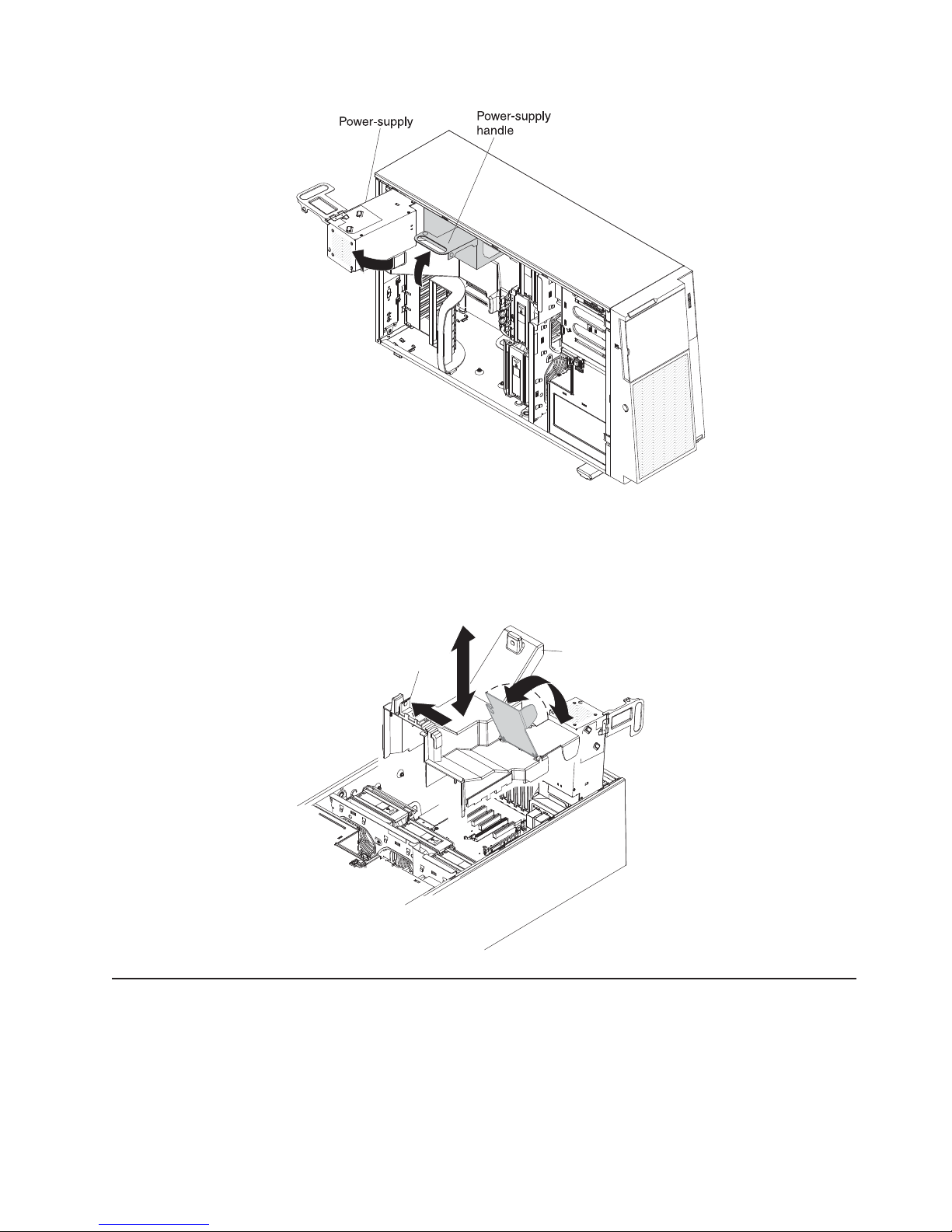
7. Remove the air baffle assembly. Lift the rear or the air baffle up; then, press the
blue tab (on top of the fan cage) on the air baffle assembly to the left and lift it
from the server and set it aside.
Note: It might be easier to remove the air baffle if you lift up the plastic tab that
is over the DIMMs in the rear of the server.
Air baffle
pinch tab
Removing the fan cage assembly
To remove the fan cage assembly, complete the following steps:
1. Read the safety information that begins on page vii and “Installation guidelines”
on page 32.
2. Turn off the server and peripheral devices, and disconnect the power cords and
all external cables.
3. Carefully lay the server on its side so that it is lying flat and facing up.
Air baffle
Chapter 2. Installing optional devices 43
Page 62

Note: Be careful and do not drop the server.
4. Unlock the left-side cover.
5. Remove the left-side cover (see “Removing the left-side cover” on page 36).
6. Rotate the power-supply cage assembly out of the chassis. Lift up the
power-supply cage handle and pull the power-supply cage assembly all the way
up until the retainer latch locks the cage in place on the chassis.
7. Remove the air baffle (see “Removing the air baffle” on page 42
Note: It might be easier to remove the air baffle if you lift up the tab that is over
the DIMMs in the rear of the server.
44 System x3400 M2 Types 7836 and 7837: Installation and User’s Guide
Page 63

8. Press in on the fan cage assembly release buttons on both sides of the chassis
to release the fan cage assembly from the connector on the chassis. Lift the fan
cage assembly up and out of the chassis and set it aside.
Chapter 2. Installing optional devices 45
Page 64

Installing a memory module
The following notes describe the types of dual inline memory modules (DIMMs) that
the server supports and other information that you must consider when installing
DIMMs (see “System-board option connectors” on page 30 for the location of the
DIMM connectors):
Attention: Do not mix UDIMMs and RDIMMs in the same server.
v The server supports industry-standard, 800, 1066, or 1333 MHz,
PC3-10600R-999 (single-rank or dual-rank) double-data-rate 3 (DDR3),
registered, synchronous dynamic random-access memory (SDRAM) dual inline
memory modules (DIMMs) with error correcting code (ECC). For a list of
supported options for the server, see http://www.ibm.com/servers/eserver/
serverproven/compat/us/; then, select your country and navigate to the list of
options for the server.
– The specifications of a DDR3 DIMM are on a label on the DIMM, in the
following format.
ggg eRxff-PC3-wwwwwm-aa-bb-cc
where:
ggg is the total capacity of the DIMM (for example, 1GB, 2GB, or 4GB)
e is the number of ranks
1 = single-rank
2 = dual-rank
4 = quad-rank
ff is the device organization (bit width)
4 = x4 organization (4 DQ lines per SDRAM)
8 = x8 organization
16 = x16 organization
wwwww is the DIMM bandwidth, in MBps
6400 = 6.40 GBps (PC3-800 SDRAMs, 8-byte primary data bus)
8500 = 8.53 GBps (PC3-1066 SDRAMs, 8-byte primary data bus)
10600 = 10.66 GBps (PC3-1333 SDRAMs, 8-byte primary data bus)
12800 = 12.80 GBps PC3-1600 SDRAMs, 8-byte primary data bus)
m is the DIMM type
E = Unbuffered DIMM (UDIMM) with ECC (x72-bit module data bus)
R = Registered DIMM (RDIMM)
U = Unbuffered DIMM with no ECC (x64-bit primary data bus)
aa is the CAS latency, in clocks at maximum operating frequency
bb is the JEDEC SPD Revision Encoding and Additions level
cc is the reference design file for the design of the DIMM
d is the revision number of the reference design of the DIMM
v The server supports a maximum of 12 single-rank or dual-rank DIMMs.
Note: To determine the type of a DIMM, see the label on the DIMM. The
information on the label is in the format xxxxx nRxxx PC3-xxxxx-xx-xx-xxx. The
numeral in the sixth numerical position indicates whether the DIMM is single-rank
(n=1) or dual-rank (n=2).
46 System x3400 M2 Types 7836 and 7837: Installation and User’s Guide
Page 65

v The server supports three single-rank or dual-rank DIMMs per channel. The
following table shows an example of the maximum amount of memory that you
can install, using ranked DIMMs.
Table 6. Maximum memory installation using ranked DIMMs
Number of DIMMs DIMM type DIMM size Total memory
12 Single-rank DIMMs 4 GB 48 GB
12 Dual-rank DIMMs 4 GB 48 GB
12 Dual-rank DIMMs 8 GB 96 GB
v The DIMM options that are available for the server are 1 GB, 2 GB, 4 GB, and 8
GB. The server supports a minimum of 2 GB and a maximum of 96 GB of
system memory.
Note: The amount of usable memory is reduced depending on the system
configuration. A certain amount of memory must be reserved for system
resources. To view the total amount of installed memory and the amount of
configured memory, run the Setup utility. For additional information, see “Using
the Setup utility” on page 106.
v A minimum of one DIMM must be installed for each microprocessor. For
example, you must install a minimum of two DIMMs if the server has two
microprocessors installed. However, to improve system performance, install a
minimum of three DIMMs for each microprocessor.
v The maximum operating speed of the server is determined by the slowest DIMM
install in the server.
v The server comes with a minimum of two 1 GB DIMMs, installed in slots 3 and 6.
v When you install additional DIMMs in independent mode, install them in the order
shown in the following table to optimize system performance. All three channels
on the memory interface for each microprocessor can be populated in any order
and have no matching requirements.
Table 7. Independent mode DIMM installation sequence
Installed microprocessors DIMM connector population sequence
Microprocessor socket 1 3, 6, 8, 2, 5, 7
Microprocessor socket 2 11, 14, 16, 10, 13, 15
Note: DIMM connectors 1, 4, 9, and 12 are not functional. Do not install DIMMs in these
connectors.
v The server supports memory mirroring (mirroring mode):
– Memory-mirroring mode replicates and stores data on two pairs of DIMMs
within two channels (channels 0 and 1) simultaneously. If a failure occurs, the
memory controller switches from the primary pair of memory DIMMs to the
backup pair of DIMMs. To enable memory mirroring through the Setup utility,
select System Settings → Memory. For more information, see “Using the
Setup utility” on page 106. When you use the memory mirroring feature,
consider the following information:
- When you use memory mirroring, you must install a pair of DIMMs at a
time. One DIMM must be in channel 0, and the mirroring DIMM must be in
the same slot in channel 1. The two DIMMs in each pair must be identical
in size, type, and rank (single or dual) , and organization, but not in speed.
The channels run at the speed of the slowest DIMM in any of the channels.
Chapter 2. Installing optional devices 47
Page 66

- Channel 2, DIMM connectors 7, 8, 15, and 16 are not used in
memory-mirroring mode.
- The maximum available memory is reduced to half of the installed memory
when memory mirroring is enabled. For example, if you install 48 GB of
memory, only 24 GB of addressable memory is available when you use
memory mirroring.
The following table lists the usable DIMM connectors on each memory channel.
Table 8. Connectors on each memory channel
Memory channel DIMM connectors
Channel 0 2, 3, 10, 11
Channel 1 5, 6, 13, 14
Channel 2 7, 8, 15, 16
The following table lists the installation sequence for installing DIMMs in
memory-mirroring mode.
Table 9. Memory-mirroring mode DIMM population sequence
Number of installed
DIMMs
First pair of DIMMs 1 3, 6
Second pair of DIMMs 1 2, 5
Third pair of DIMMs 2 11, 14
Fourth pair of DIMMs 2 10, 13
Note: DIMM connectors 7, 8, 15, and 16 are not used in memory-mirroring mode and DIMM
connectors 1, 4, 9, and 12 are not functional on this server. Do not install DIMMs in these
connectors.
microprocessors DIMM connector
v When you install or remove DIMMs, the server configuration information
changes. When you restart the server, the system displays a message that
indicates that the memory configuration has changed.
Attention: Static electricity that is released to internal server components when
the server is powered-on might cause the server to stop, which could result in the
loss of data. To avoid this potential problem, always use an electrostatic-discharge
wrist strap or other grounding system when working inside the server with the
power on.
To install a DIMM, complete the following steps:
1. Read the safety information that begins on page vii and “Installation guidelines”
on page 32.
2. Turn off the server and peripheral devices, and disconnect the power cords
and all external cables.
3. Unlock the left-side cover.
4. Remove the left-side cover (see “Removing the left-side cover” on page 36).
5. Rotate the power-supply cage assembly out of the chassis. Lift up the
power-supply cage handle and pull the power-supply cage assembly all the
way up until the retainer latch locks the cage in place on the chassis.
48 System x3400 M2 Types 7836 and 7837: Installation and User’s Guide
Page 67

6. Remove the air baffle (see “Removing the air baffle” on page 42).
7. Locate the DIMM connectors on the system board. Determine the connector in
which you will install the DIMM. Install the DIMMs in the sequence indicated
earlier in this section.
Note: DIMM connectors 1, 4, 9, and 12 are not functional in this server. Do
not install DIMMs in these connectors.
DIMM 16
DIMM 15
DIMM 14
DIMM 12 (reserved)
DIMM 13
DIMM 11
DIMM 10
DIMM 9 (reserved)
Do not insert a memory DIMM in this connector.This DIMM slot is not supported in this model.
Do not insert a memory DIMM in this connector.This DIMM slot is not supported in this model.
Do not insert a memory DIMM in this connector.This DIMM slot is not supported in this model.
Do not insert a memory DIMM in this connector.This DIMM slot is not supported in this model.
DIMM 8
DIMM 7
DIMM 6
DIMM 5
DIMM 4 (reserved)
DIMM 3
DIMM 2
DIMM 1 (reserved)
Attention: To avoid breaking the retaining clips or damaging the DIMM
connectors, open and close the clips gently.
Chapter 2. Installing optional devices 49
Page 68

8. Open the retaining clips and, if necessary, remove any existing DIMM.
9. Touch the static-protective package that contains the DIMM to any unpainted
metal surface on the server. Then, remove the new DIMM from the package.
10. Turn the DIMM so that the DIMM keys align correctly with the connector.
11. Insert the DIMM into the connector by aligning the edges of the DIMM with the
slots at the ends of the DIMM connector. Firmly press the DIMM straight down
into the connector by applying pressure on both ends of the DIMM
simultaneously. The retaining clips snap into the locked position when the
DIMM is firmly seated in the connector. If there is a gap between the DIMM
and the retaining clips, the DIMM has not been correctly installed. Open the
retaining clips, remove the DIMM, and then reinsert it.
12. Install the air baffle (see “Replace the air baffle” on page 98).
13. Rotate the power-supply cage assembly back into the server. Press the
power-supply cage release tab and rotate the power-supply cage assembly
into the chassis.
50 System x3400 M2 Types 7836 and 7837: Installation and User’s Guide
Page 69

If you have other options to install or remove, do so now; otherwise, go to
“Completing the installation” on page 97.
Chapter 2. Installing optional devices 51
Page 70

Installing drives
Depending on the server model, the server might come with a SATA attached
DVD-ROM drive in bay 1.
The following are illustrations of the server and the locations of the drive bays. Your
hardware might differ, depending on the model.
The following illustration shows the locations of the drive bays in the 2.5-inch
hot-swap SAS or hot-swap SATA hard disk drive server models.
Bay 1
Bay 2
Bay 3
Bay 8
Bay 9
Bay 10
Bay 11
Bay 4
Bay 5
Bay 6
Bay 7
52 System x3400 M2 Types 7836 and 7837: Installation and User’s Guide
Page 71

The following illustration shows the locations of the drive bays in the 3.5-inch
hot-swap SAS or hot-swap SATA hard disk drive server models.
The following illustration shows the locations of the drive bays in the 3.5-inch
simple-swap SATA hard disk drive server models.
The following notes describe the types of drives that the server supports and other
information that you must consider when installing a drive:
Chapter 2. Installing optional devices 53
Page 72

v Make sure that you have all the cables and other equipment that are specified in
the documentation that comes with the drive.
v Check the instructions that come with the drive to see whether you have to set
any switches or jumpers on the drive. If you are installing a SAS or SATA device,
be sure to set the SAS or SATA ID for that device.
v Optional external tape drives and DVD-ROM drives are examples of
removable-media drives. You can install removable-media drives only in bays 1,
2, and 3.
v To install a 3.5-in. drive in a 5.25-in. bay, you must use a 5.25-in. conversion kit.
v The electromagnetic interference (EMI) integrity and cooling of the server are
protected by having all bays and PCI slots covered or occupied. When you install
a drive or PCI adapter, save the EMC shield and filler panel from the bay or the
PCI adapter slot cover in the event that you later remove the drive or adapter.
v For a complete list of supported options for the server, see http://www.ibm.com/
servers/eserver/serverproven/compat/us/.
54 System x3400 M2 Types 7836 and 7837: Installation and User’s Guide
Page 73

Installing a DVD drive
To install a DVD drive, complete the following steps:
1. Read the safety information that begins on page vii and “Installation guidelines”
on page 32.
2. Turn off the server and peripheral devices, and disconnect the power cords
and all external cables.
3. Unlock the left-side cover.
4. Remove the left-side cover (see “Removing the left-side cover” on page 36).
5. Open the bezel. Place your finger on the pull point area on the left side of the
bezel door and rotate it away from the server.
6. Remove the EMC shield from the bay in which you want to install the drive.
Note: If you are installing a drive that contains a laser, observe the following
safety precaution.
Chapter 2. Installing optional devices 55
Page 74

Statement 3:
CAUTION:
When laser products (such as CD-ROMs, DVD drives, fiber optic devices,
or transmitters) are installed, note the following:
v Do not remove the covers. Removing the covers of the laser product
could result in exposure to hazardous laser radiation. There are no
serviceable parts inside the device.
v Use of controls or adjustments or performance of procedures other
than those specified herein might result in hazardous radiation
exposure.
DANGER
Some laser products contain an embedded Class 3A or Class 3B laser
diode. Note the following.
Laser radiation when open. Do not stare into the beam, do not view
directly with optical instruments, and avoid direct exposure to the
beam.
Class 1 Laser Product
Laser Klasse 1
Laser Klass 1
Luokan 1 Laserlaite
Appareil A Laser de Classe 1
`
7. Rotate the power-supply cage assembly out of the chassis. Lift up the
power-supply cage handle and pull the power-supply cage assembly all the
way up until the retainer latch locks the cage in place on the chassis.
56 System x3400 M2 Types 7836 and 7837: Installation and User’s Guide
Page 75

8. Remove the air baffle (see “Removing the air baffle” on page 42.
9. Press in on the fan cage assembly release buttons on the sides of the chassis
to release the fan cage assembly from the connector on the chassis. Lift the
fan cage assembly up and out of the chassis and set it aside.
10. Touch the static-protective package that contains the DVD drive to any
unpainted metal surface on the server; then, remove the DVD drive from the
package and place it on a static-protective surface.
11. Set any jumpers or switches on the drive according to the documentation that
comes with the drive.
Chapter 2. Installing optional devices 57
Page 76
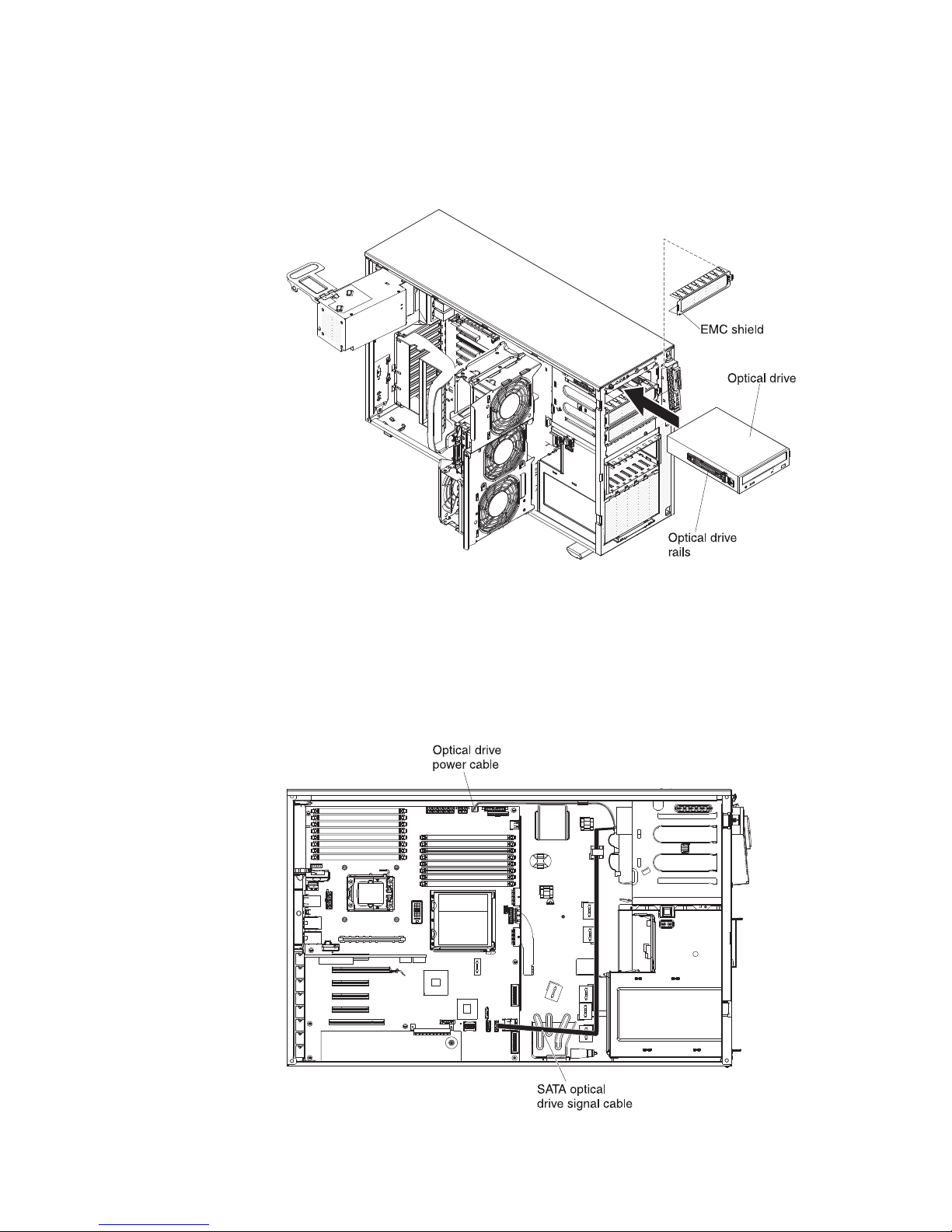
Note: You might find it easier to install the new drive from the front and then
attach the cables.
12. Remove the blue optical drive rails from the inside of the drive bay in which
you want to install the drive. Align the holes on the blue optical drive rails with
the pins on the side of the drive and snap the optical drive rails onto the drive.
13. If you are installing a 5.25-in. drive in bay 2, push the drive into the bay until it
locks into place. If you are installing a 3.5-in. drive in bay 2, attach the 5.25-in.
conversion kit and push the drive into the drive bay.
14. Connect power and signal cables to the drive and the connectors on the
system board.
15. Route the signal cable through the plastic slot on the bottom of the chassis
underneath the fan cage assembly so that it does not block the airflow to the
rear of the drives as shown in the following illustration:
58 System x3400 M2 Types 7836 and 7837: Installation and User’s Guide
Page 77

See “Power and signal cables for internal drives” on page 69 for more cabling
information.
16. If you have another drive to install or remove, do so now.
17. Reinstall the fan cage assembly. Align the fan cage assembly over the fan
cage assembly slot and with the connector on the system board. Lower the fan
cage assembly into the chassis and press down firmly until the fan cage
assembly is seated firmly in place.
18. Rotate the power-supply cage assembly back into the server. Press the
power-supply cage release tab and rotate the power-supply cage assembly
into the chassis.
19. Close the bezel.
If you have other options to install or remove, do so now; otherwise go to
“Completing the installation” on page 97.
Installing an optional tape drive
To install a optional tape drive, complete the following steps.
1. Read the safety information that begins on page vii and “Installation guidelines”
on page 32.
2. Turn off the server and peripheral devices, and disconnect the power cords
and all external cables.
3. Unlock the left-side cover.
4. Remove the left-side cover (see “Removing the left-side cover” on page 36.
5. Open the bezel. Place your finger on the pull point area on the left side of the
bezel door and rotate it away from the server.
Chapter 2. Installing optional devices 59
Page 78
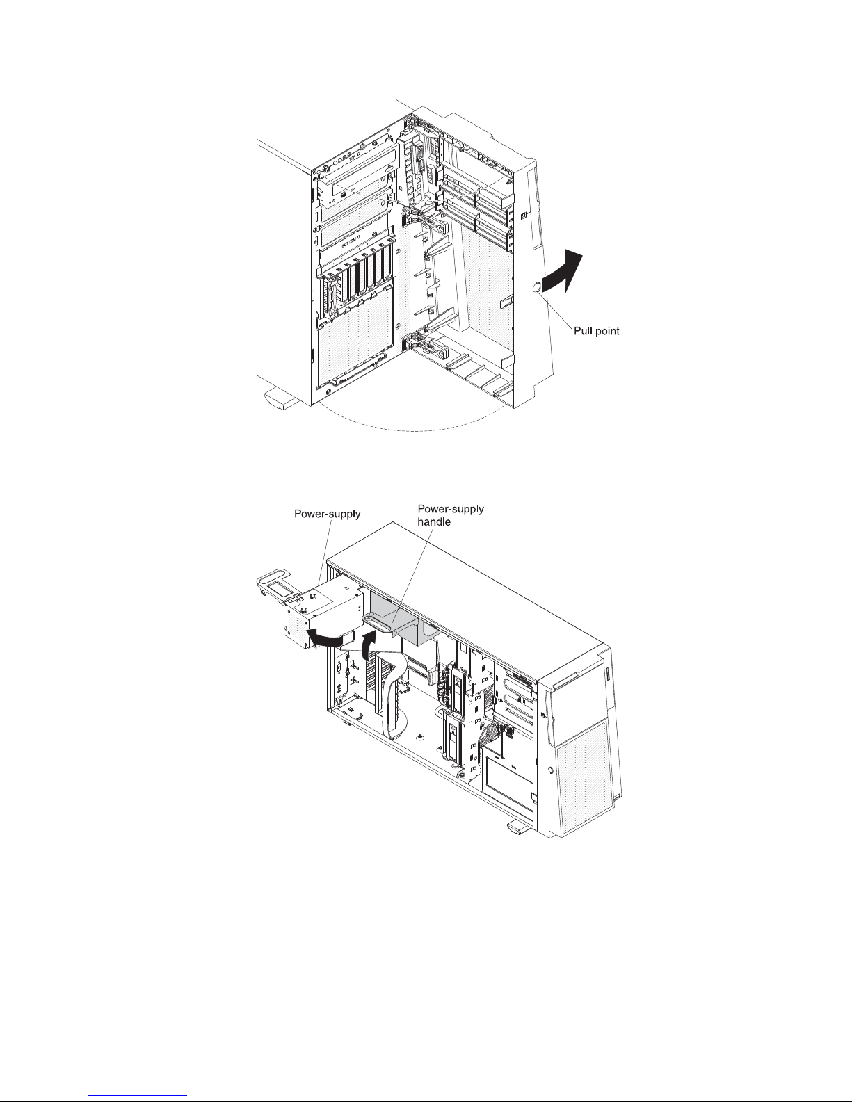
6. Rotate the power-supply cage assembly out of the chassis. Lift up the
power-supply cage handle and pull the power-supply cage assembly all the
way up until the retainer latch locks the cage in place on the chassis.
7. Remove the air baffle (see “Removing the air baffle” on page 42).
8. Remove the fan cage assembly. Press in on the fan cage assembly release
buttons on the sides of the chassis to release the fan cage assembly from the
connector on the chassis. Lift the fan cage assembly up and out of the chassis
and set it aside.
9. Remove the EMC shields from the bays in which you want to install the tape
drive.
60 System x3400 M2 Types 7836 and 7837: Installation and User’s Guide
Page 79

10. Touch the static-protective package that contains the tape drive to any
unpainted metal surface on the server; then, remove the tape drive from the
package and place it on a static-protective surface.
11. Install the blue rails on the sides of the tape drive.
12. Align the rails on tape drive with the guides in the drive bay; then, slide the
tape drive into the server from the front of the server until it click into place.
13. If the tape drive comes with screws, secure the tape drive to the chassis with
the supplied screws.
14. Connect one of the connectors on the optical drive power cable to the tape
drive. If however, you are installing an RDX internal USB tape drive, you will
need to install the SATA to traditional power converter cable. Locate the SATA
to traditional power converter cable that came with the server in the plastic bag
with the drive rails; then connect one end of the converter cable to the third
connector (the default connector) on the optical drive power cable and connect
the other end of the cable to the tape drive as shown in the following
illustrations.
Power
converter
cable
Connects to
optical power cable
Connects to
tape drive
Chapter 2. Installing optional devices 61
Page 80

Optical power cable
SATA connector
Power converter
cable
Tape drive
15. Connect one end of the tape drive signal cable to the tape drive and the other
end to the connector on the system board. Route the cable through the plastic
slots on the bottom of the chassis underneath the fan cage assembly as
shown in the following illustration:
Optical drive
power cable
connector
USB signal
cable connector
USB signal
cable
Optical drive
power cable
See “Power and signal cables for internal drives” on page 69 for more cabling
information.
62 System x3400 M2 Types 7836 and 7837: Installation and User’s Guide
SATA optical
drive signal cable
Page 81

16. Reinstall the fan cage assembly. Align the fan cage assembly over the fan
cage assembly slot and with the connector on the system board. Lower the fan
cage assembly into the chassis and press down firmly until the fan cage
assembly is seated firmly in place.
Note: Make sure that all wires and cables inside the server are routed
correctly before installing the fan cage assembly. Wiring that is not properly
routed could be damaged or might prevent the fan cage assembly from seating
properly in the server.
17. Rotate the power-supply cage assembly back into the server. Press the
power-supply cage release tab and rotate the power-supply cage assembly
into the chassis.
18. Close the bezel.
If you have other options to install or remove, do so now; otherwise go to
“Completing the installation” on page 97.
Installing a hot-swap hard disk drive
Some server models come with hot-swap SAS or SATA hot-swap hard disk drives.
Before you install a hot-swap hard disk drive, read the following information:
v The hot-swap drives must be either all SAS hard disk drives or all SATA hard
disk drives; do not mix SAS and SATA drives in the server.
v The hot-swap hard disk drive models come with the following drives (depending
on your model):
– Four 3.5-inch hot-swap SAS or SATA hard disk drives
– Eight or sixteen 2.5-inch hot-swap SAS or SATA hard disk drives
v The sequence for installing the 3.5-inch hard disk drives in the four-bay models is
to install the drives starting from the left bay (bay 4) and go to the right bay (bay
7) in that order.
v The sequence for installing the 2.5-inch hard disk drives in the eight-bay models
is to install the drives starting from the right bay (bay 4) and go to the left bay
(bay 11) in that order.
v The hot-swap drives are arranged horizontally in the standard hard disk drive
cage; the drive numbers are 0 through 7 (right to left) on models with eight hard
disk drives and 8 through 15 (right to left) on servers with 16 hard disk drives.
When you install hard disk drives, start with drive 0.
v Inspect the drive tray for signs of damage.
v Make sure that the drive is correctly installed in the tray.
v You do not have to turn off the server to install hot-swap drives in the hot-swap
drive bays.
v All hot-swap drives must have the same throughput speed rating; mixing speed
ratings might cause all drives to operate at the lower throughput speed.
v The drive ID for each hot-swap hard disk drive is printed on the bezel.
v To maintain proper system cooling, do not operate the server for more than 10
minutes without either a drive or a filler panel installed in each drive bay.
Attention: Static electricity that is released to internal server components when
the server is powered-on might cause the server to stop, which could result in the
loss of data. To avoid this potential problem, always use an electrostatic-discharge
wrist strap or other grounding system when working inside the server with the
power on.
Chapter 2. Installing optional devices 63
Page 82

To install a hot-swap hard disk drive, complete the following steps:
1. Read the safety information that begins on page vii and “Installation guidelines”
on page 32.
2. Unlock the left-side cover.
3. Open the bezel. (see “Removing the bezel” on page 36).
4. Place your finger on the pull point area on the left side of the bezel door and
rotate it away from the server.
Note: After you rotate the bezel beyond 90°, you can pull the bezel off the
server and set it aside, if you want to remove it completely.
5. Remove the EMC shield from the bay in which you want to install the drive.
6. Touch the static-protective package that contains the drive to any unpainted
metal surface on the server; then, remove the drive from the package and place
it on a static-protective surface.
7. Install the hard disk drive in the hot-swap bay:
a. Make sure that the drive tray handle is open.
b. Align the drive assembly with the guide rails in the bay.
The following is the 2.5-inch hot-swap model:
64 System x3400 M2 Types 7836 and 7837: Installation and User’s Guide
Page 83

The following is the 3.5-inch hot-swap model:
c. Gently slide the drive assembly into the drive bay until the drive stops.
d. Push the drive tray handle to the closed (locked) position.
e. See “Power and signal cables for internal drives” on page 69 and the
Problem Determination and Service Guide for cabling information, if needed.
f. Check the hard disk drive status indicator to make sure that the hard disk
drive is operating correctly. (You might have to restart the server before the
drive is recognized.) If the amber hard disk drive status LED for a drive is lit
continuously, it indicates that the drive is faulty and must be replaced. If the
amber hard disk drive status LED for a drive is flashing slowly, this indicates
that the drive is being rebuilt. If the amber hard disk drive status LED for a
drive is flashing rapidly, this indicates that the controller is identifying the
drive. If the green hard disk drive activity LED is flashing, it indicates that the
drive is in use.
Chapter 2. Installing optional devices 65
Page 84

Note: If the server is configured for RAID operation using an optional
ServeRAID adapter, you might have to reconfigure your disk arrays after
installing hard disk drives. See the ServeRAID documentation on the IBM
Web site at http://www.ibm.com/systems/support/ for information about
configuring and managing RAID arrays.
g. Close the bezel.
8. If you are installing additional hot-swap hard disk drives, do so now.
If you have other options to install or remove, do so now; otherwise go to
“Completing the installation” on page 97.
IDs for hot-swap hard disk drives
Hot-swap server models have drive bays that are connected to a SAS/SATA
backplane. This backplane, also known as the hot-swap-drive backplane, is the
printed circuit board behind these bays.
The hot-swap-drive backplane controls the IDs for the internal hot-swap drive bays.
The following tables list the IDs for the hard disk drives and backplane that are
connected to hot-swap models.
Table 10. IDs for the four-bay 3.5-inch hot-swap drive models
Drive bay number ID
Drive bay 4 0
Drive bay 5 1
Drive bay 6 2
Drive bay 7 3
Table 11. IDs for the eight-bay 2.5-inch hot-swap models
Drive bay number ID
Drive bay 4 0
Drive bay 5 1
Drive bay 6 2
Drive bay 7 3
Drive bay 8 4
Drive bay 9 5
Drive bay 10 6
Drive bay 11 7
Installing a simple-swap SATA hard disk drive
Some server models come with four 3.5-inch simple-swap SATA hard disk drives
that are accessible from the front of the server. You must turn off the server before
installing simple-swap drives in the server. Before you install a simple-swap SATA
hard disk drive, read the following information:
v You can only install four simple-swap SATA hard disk drives in the server.
v The sequence for installing the hard disk drives is to install the drives starting
from the left bay (bay 4) and go the right bay (bay 7) in that order.
To install a simple-swap hard disk drive, complete the following steps:
66 System x3400 M2 Types 7836 and 7837: Installation and User’s Guide
Page 85

1. Read the safety information that begins on page vii and “Installation guidelines”
on page 32.
2. Turn off the server and peripheral devices and disconnect all external cables
and power cords.
3. Unlock the left-side cover.
4. Remove the left-side cover (see “Removing the left-side cover” on page 36).
5. Open the bezel. Place your finger on the pull point area on the left side of the
bezel door and rotate it away from the server.
6. Remove the filler panel from the drive bay in which you want to install the
drive.
7. Grasp the tab on the drive bay EMC shield and rotate it to the open position.
Chapter 2. Installing optional devices 67
Page 86

8. Touch the static-protective package that contains the drive to any unpainted
metal surface on the server; then, remove the drive from the package and
place it on a static-protective surface.
9. Align the drive assembly with the guide rails in the bay (the connector end of
the drive goes in first).
10. Press the drive assembly loops toward each other; then, carefully slide the
drive assembly into the drive bay until it stops and release the loops.
Note: Do not release the loops on the drive assembly until it is completely
seated.
11. See “Power and signal cables for internal drives” on page 69 and the Problem
Determination and Service Guide for cabling information, if needed.
12. Close the drive bay EMC shield.
13. Close the bezel.
If you have other options to install or remove, do so now; otherwise, go to
“Completing the installation” on page 97.
The simple-swap-drive backplate controls the IDs for the internal simple-swap drive
bays. The following table lists the IDs for the hard disk drives and backplate that
are connected to simple-swap models.
Table 12. IDs for the 3.5-inch simple-swap drive models
Drive bay number ID
Drive bay 4 0
Drive bay 5 1
Drive bay 6 2
Drive bay 7 3
68 System x3400 M2 Types 7836 and 7837: Installation and User’s Guide
Page 87

Power and signal cables for internal drives
The server uses cables to connect SATA attached, simple-swap SATA, hot-swap
SATA and hot-swap SAS devices to the power supply and to the system board.
(See “System-board internal connectors” on page 24 for the location of
system-board connectors.) Review the following information before connecting
power and signal cables to internal drives:
v The drives that are preinstalled in the server come with power and signal cables
attached. If you replace any drives, remember which cable is attached to which
drive.
v When you route a cable, make sure that it does not block the airflow to the rear
of the drives or over the microprocessor or DIMMs.
The following cables are provided:
v The DVD drive is attached to an ATA signal cable. The blue connector is
attached to the SATA 0 (optical drive connector) on the system board. The
connector on the other end is attached to the SATA device. The middle connector
attaches to an optional optical device or tape drive. A separate power cable
provides power to the device from the system board.
v Simple-swap SATA models: The simple-swap SATA models come with a
combination signal/power cable that connects to the connector on the system
board and the simple-swap SATA backplate to provide signal and power to the
simple-swap SATA drives. Connect the power connector on the split end of the
cable to the Hard disk drive backplane power connector (labeled A) on the
system board and connect the signal connector on the split end of the cable to
the Simple-swap SATA signal cable connector on the system board. The other
end of the combination signal/power cable has a signal cable connected to each
drive bay signal connector on the simple-swap SATA backplate and a power
cable connected to each drive bay power connector on the simple-swap SATA
backplate.
v Hot-swap SAS or hot-swap SATA models:
– The 2.5-inch hot-swap SAS and hot-swap SATA models come with the
following cables to provide signal and power to the hot-swap SAS/SATA
drives:
- Four single signal cables (thick red and black) that connects to the signal
cable connectors on the hard disk drive backplanes (the backplanes are
labeled A0 and A1) and the connectors on the SAS/SATA RAID adapter
(see the ServeRAID adapters installation instructions in this document for
more cabling information).
- Two split power cables (red/yellow/black). The end of the power cable with
the single connector connects to the Hard disk drive backplane power
connector (the power connector labeled A) on the system board and the
end of the power cable with the two connectors, connects to the power
connectors on the hard disk drive backplanes (the backplanes are labeled
A0 and A1).
- Two split configuration signal cables (black). The end of the configuration
signal cable with the single connector connects to the Hard disk drive
backplane configuration signal connector (the configuration connector
labeled A) on the system board and the end of the configuration signal
cable with the two connectors, connects to the configuration signal
connectors on the hard disk drive backplanes (the backplanes are labeled
A0 and A1).
Chapter 2. Installing optional devices 69
Page 88

– The 3.5-inch hot-swap SAS and hot-swap SATA models come with the
following to provide signal and power to the 3.5-inch hot-swap SAS/SATA
drives.:
- A single signal cable (thick red and black) that connects to the hard disk
- A single power cable (red/yellow/black) that connects to the Hard disk
- A single configuration signal cable (black) that connects to the Hard disk
For more information about the requirements for SAS/SATA cables and connecting
SAS/SATA devices, see the documentation that comes with these devices.
For a list of supported options for the server, see http://www.ibm.com/servers/
eserver/serverproven/compat/us/.
Installing an adapter
The following notes describe the types of adapters that the server supports and
other information that you must consider when installing an adapter. Adapter that
the server supports might vary, depending on your server model.
v Locate the documentation that comes with the adapter and follow those
instructions in addition to the instructions in this section. If you must change the
switch setting or jumper settings on the adapter, follow the instructions that come
with the adapter.
v Read the documentation that comes with your operating system.
v Use PCI slot 2 for video adapters.
v Do not set the maximum digital video adapter resolution above 1600 x 1200 at
85 Hz for an LCD monitor. This is the highest resolution that is supported for any
add-on video adapter that you install in the server.
v Any high-definition video-out connector or stereo connector on any add-on video
adapter is not supported
v The server provides up to eight adapter connectors, or slots as follows
(depending on your server model):
drive backplane and one of the connectors on the SAS/SATA RAID adapter
(see the ServeRAID adapters installation instructions in this document for
more cabling information).
drive backplane power connector (the power connector labeled A) on the
system board and to the power connector on the hard disk drive backplane.
drive backplane configuration signal connector (the configuration
connector labeled A) on the system board and the configuration signal
connector on the hard disk drive backplane.
Note: The x8 (x4) designation for slot 3 (for example) identifies an x8 slot that is
designed to support x8 adapters and x4 adapters that can downshift to operate
at the x4 bandwidth. If you install an x8 adapter in slot 3 that can downshift to
the x4 bandwidth, it will run at the x4 bandwidth. The x8 connector can be used
for x4 and x8 adapters. These same rules apply to the other PCI slots also.
Check the information that comes with your adapter for compatibility information.
– Slots on the system board:
- Slot 1, PCI Express Gen 2 x8 (x8)
- Slot 2, PCI Express Gen 2 x16 (x8)
- Slot 3, PCI Express Gen 2 x8 (x4)
- Slot 4, PCI Express Gen 2 x8 (x4)
- Slot 5, PCI Express Gen 2 x8 (x8)
70 System x3400 M2 Types 7836 and 7837: Installation and User’s Guide
Page 89

- Slot 6, PCI 32-bit/33 MHz
– If you install the optional one-slot PCI extender card in the server:
- One additional PCI Express Gen 1 x8 (x4) slot is available
– If you install the optional two-slot PCI extender card in the server:
- Two additional PCI-X 32-bit/64-bit 133/100/66 MHz slots are available
®
v You can install full-length adapters that are included in the ServerProven
list in
slots 2, 3, 4, and 5 on the system board, and the slots on the one-slot or two-slot
extender cards. You can only install half-length adapters in slots 1 and 6.
v The 32-bit slot 6 supports 5.0 V keyed PCI adapters; they do not support 3.3 V
keyed adapters. Universal adapters are supported in slots 4 and 5 if they are
universally keyed.
v You can install the IBM ServeRAID-BR10i SAS/SATA controller, the optional IBM
ServeRAID-MR10i SAS/SATA controller, or the optional IBM ServeRAID-MR10is
VAULT SAS/SATA controller in slots 1 of hot-swap SAS or hot-swap SATA
models. These ServeRAID adapters are not supported on the simple-swap
models.
v The ServeRAID-BR10i adapter comes standard on hot-swap SAS and hot-swap
SATA models and provides RAID levels 0, 1, and 1E support. You can order the
ServeRAID-MR10i adapter which provides RAID levels 0, 1, 5, 6, 10, 50, and 60
support, and the optional ServeRAID-MR10is adapter with an encryption 1078
DE chip provides RAID levels 0, 1, 5, 6, 10, 50, and 60 support.
To ensure that any of your ServeRAID 10i, 10is, or 10M adapters function
properly on UEFI-based servers, make sure that the adapter firmware level is
updated to at least 11.x.x-XXX , and the supporting drivers.
Attention: Some cluster solutions require specific code levels or coordinated
code updates. If the device is part of a cluster solution, verify that the latest level
of code is supported for the cluster solution before you update the code.
v The server scans PCI Express slot 1, PCI-X slots 4 and 5, and PCI-Express slots
2 and 3 to assign system resources. Then, the server starts the devices in the
following order, if you have not changed the default startup sequence: PCI
Express slot 1, PCI-X slots 4 and 5, PCI Express slot 2, PCI slot 6, and PCI
Express slot 3.
v For a list of supported options for the server, see http://www.ibm.com/servers/
eserver/serverproven/compat/us/.
To install an adapter, complete the following steps:
Note: The instructions in this section apply to any PCI adapter (for example, video
graphics adapters or network adapters).
1. Read the safety information that begins on page vii and “Installation guidelines”
on page 32.
2. Turn off the server and peripheral devices and disconnect all external cables
and power cords; then, remove the left-side cover (see “Removing the left-side
cover” on page 36).
3. Carefully lay the server on its side so that it is lying flat and facing up.
Note: Be careful and do not drop the server.
4. Follow the cabling instructions that come with the adapter to set jumpers or
switches, if there are any. Route the adapter cables before you install the
adapter.
5. Rotate the rear adapter-retention bracket to the open (unlocked) position.
Chapter 2. Installing optional devices 71
Page 90

6. If you are installing a full-length adapter, press on the release lever on the right
side of the front adapter-retention bracket to release the retaining tab on the
left side of the bracket.
7. Remove the screw that secures the expansion-slot cover to the chassis. Store
the expansion-slot cover and screw in a safe place for future use.
Note: Expansion-slot covers must be installed on all vacant slots. This
maintains the electronic emissions standards of the server and ensures proper
ventilation of server components.
8. Touch the static-protective package that contains the adapter to any unpainted
metal surface on the server. Then, remove the adapter from the
static-protective package. Avoid touching the components and gold-edge
connectors on the adapter.
9. If you are installing a full-length adapter, remove the blue adapter guide (if any)
from the end of the adapter.
Adapter guide
10. Carefully grasp the adapter by the top edge or upper corners, and move the
adapter directly from the static-protective package to the expansion slot. Align
the adapter with the expansion slot guides; then, press the adapter firmly into
the expansion slot. For a full-length adapter, make sure that the front edge of
the adapter is properly seated in the correct slot in the front adapter-retention
bracket.
Note: Make sure that the adapter is seated correctly in the expansion slot
before you turn on the server. Incomplete installation of an adapter might
damage the system board or the adapter.
72 System x3400 M2 Types 7836 and 7837: Installation and User’s Guide
Page 91

11. Connect required cables to the adapter. Route cables so that they do not block
the flow of air from the fans.
12. Rotate the rear adapter-retention bracket to the closed (locked) position.
13. Rotate the front adapter-retention bracket to the closed (locked) position.
If you have other options to install or remove, do so now; otherwise, go to
“Completing the installation” on page 97.
Installing a second microprocessor
The following notes describe the type of microprocessor that the server supports
and other information that you must consider when installing a microprocessor:
v The server comes with one microprocessor installed, but supports up to two
microprocessors.
Note: A microprocessor must be installed and removed only by a trained service
technician.
v Read the documentation that comes with the microprocessor to determine
whether you have to update the server firmware. To download the most current
level of the firmware for your server, go to http://www.ibm.com/systems/support/,
and click Downloads and drivers.
v The first microprocessor must always be installed in microprocessor socket 1.
v When one microprocessor is installed, a heat sink filler is not required for
microprocessor socket 2; however, the air baffle must be installed to provide
proper system cooling.
v Do not remove the first microprocessor from the system board when you install
the second microprocessor.
v When you install the second microprocessor, you must also install additional
memory. See “Installing a memory module” on page 46.
v The first microprocessor voltage regulator module (VRM) is integrated on the
system board.
Chapter 2. Installing optional devices 73
Page 92

v When you install a second microprocessor, you must also install the voltage
regulator module (VRM), which comes with the microprocessor option kit, in the
VRM connector on the system board.
v Some models support dual-core microprocessors or quad-core microprocessors.
Do not mix dual-core microprocessors and quad-core microprocessors in the
same system. Install all dual-core or all quad-core microprocessors in the server.
v To ensure proper server operation when you install an additional microprocessor,
use microprocessors that have the same QuickPath Interconnect (QPI) link
speed, integrated memory controller frequency, core frequency, power segment,
internal cache size, and type. You can use the Setup utility to determine the
specific type of microprocessor that is installed on the system board.
v Mixing microprocessors of different stepping levels within the same server model
is supported. You do not have to install the microprocessor with the lowest
stepping level and features in microprocessor socket 1.
v The microprocessor speeds are automatically set for this server; therefore, you
do not have to set any microprocessor frequency-selection jumpers or switches.
v If the thermal-grease protective cover (for example, a plastic cap or tape liner) is
removed from the heat sink, do not touch the thermal grease on the bottom of
the heat sink or set down the heat sink.
v If you have to replace a microprocessor, call for service.
v To order additional microprocessor options, contact your IBM marketing
representative or authorized reseller. See http://www.ibm.com/servers/eserver/
serverproven/compat/us/ for a list of supported microprocessors.
The following illustration shows the locations of the microprocessor connectors and
the VRM connector.
To install an additional microprocessor, complete the following steps:
74 System x3400 M2 Types 7836 and 7837: Installation and User’s Guide
Page 93

1. Read the safety information beginning on page vii, and “Installation guidelines”
on page 32.
2. Turn off the server and disconnect all power cords and external cables (see
“Turning off the server” on page 22); then, unlock and remove the server cover
(see “Removing the left-side cover” on page 36).
3. Carefully lay the server on its side so that it is lying flat and facing up.
Note: Be careful and do not drop the server.
4. Rotate the power-supply cage assembly out of the chassis. Lift up the
power-supply cage handle and pull the power-supply cage assembly all the
way up until the retainer latch locks the cage in place on the chassis.
5. Remove the air baffle (see “Removing the air baffle” on page 42).
6. Install the VRM in the VRM connector:
a. Open the retaining clip on each end of the VRM connector on the system
board.
b. Turn the VRM so that the VRM keys align correctly with the slot connector.
c. Firmly press the VRM straight down into the connector by applying
d. Make sure that the retaining clips are in the locked position when the VRM
7. Locate the second microprocessor connector on the system board.
8. Install the microprocessor:
a. Touch the static-protective package that contains the microprocessor to any
b. Remove the protective cover, tape, or label from the surface of the
pressure on both ends of the VRM simultaneously.
is firmly seated in the connector.
unpainted metal surface on the server. Then, remove the microprocessor
from the package.
microprocessor socket, if any is present.
Attention: Make sure that the release latch on the microprocessor socket
is in the fully open position before you insert the microprocessor in the
socket. Failure to do so might result in permanent damage to the
microprocessor, microprocessor socket, and system board.
Chapter 2. Installing optional devices 75
Page 94

c. Rotate the microprocessor release latch on the microprocessor socket from
its closed and locked position to its fully open position.
Attention:
v Do not touch the microprocessor contact; handle the microprocessor by
the edges only. Contaminants on the microprocessor contacts, such as
oil from your skin, can cause connection failures between the contacts
and the socket.
v Handle the microprocessor carefully. Dropping the microprocessor during
installation or removal can damage the contacts.
v Do not use excessive force when pressing the microprocessor into the
socket.
v Make sure that the microprocessor is oriented and aligned with land
number 1 in the socket before you try to close the latch.
d. Align the microprocessor with the socket (note the alignment mark and the
position of the notches); then, carefully place the microprocessor on the
socket and close the microprocessor bracket frame.
e. Carefully close the microprocessor release latch to secure the
microprocessor in the socket.
9. Install the heat sink.
Attention: Do not touch the thermal grease on the bottom of the heat sink or
set down the heat sink after you remove the plastic cover. Touching the
thermal grease will contaminate it.
The following illustration shows the bottom surface of the heat sink.
a. Make sure that the heat-sink release lever is in the open position.
b. Remove the plastic protective cover from the bottom of the heat sink.
76 System x3400 M2 Types 7836 and 7837: Installation and User’s Guide
Page 95

c. If the new heat sink did not come with thermal grease, (Trained service
technician only) apply thermal grease on the microprocessor before you
install the heat sink (see the Problem Determination and Service Guide for
information on applying thermal grease).
d. Align the heat sink above the microprocessor with the thermal-grease side
down.
e. Tilt the heat sink slightly to the side and slide the heat sink flange
underneath the flange of the heat sink retainer bracket.
Chapter 2. Installing optional devices 77
Page 96

f. Press down firmly on the heat sink until it is seated securely.
g. Rotate the heat-sink lever to the closed position and hook it underneath the
lock tab.
10. Reinstall the air baffle (see “Replace the air baffle” on page 98 ).
11. Rotate the power-supply cage assembly back into the server. Press the
power-supply cage release tab and rotate the power-supply cage assembly
into the chassis.
If you have other options to install or remove, do so now. Otherwise, go to
“Completing the installation” on page 97.
Removing a power supply
When you remove or install a power supply, observe the following precautions.
Statement 8:
78 System x3400 M2 Types 7836 and 7837: Installation and User’s Guide
Page 97

CAUTION:
Never remove the cover on a power supply or any part that has the following
label attached.
Hazardous voltage, current, and energy levels are present inside any
component that has this label attached. There are no serviceable parts inside
these components. If you suspect a problem with one of these parts, contact
a service technician.
Statement 11:
CAUTION:
The following label indicates sharp edges, corners, or joints nearby.
Statement 17:
CAUTION:
The following label indicates moving parts nearby.
To remove a power supply, complete the following steps.
1. Read the safety information that begins on page vii and “Installation guidelines”
on page 32.
2. Turn off the server and all attached devices; then, disconnect all power cords
and external cables.
3. Unlock and remove the left-side cover (see “Removing the left-side cover” on
page 36).
Note: It might be helpful to lay the server on its side for the remainder of this
procedure.
4. Rotate the power-supply cage assembly out of the chassis. Lift up the
power-supply cage handle and pull the power-supply cage assembly all the way
up until the retainer latch locks the cage in place on the chassis.
Chapter 2. Installing optional devices 79
Page 98

5. Disconnect the cables from the power supply to the system board and all
internal components. Be sure to make a note of the cable routing.
Attention: Support the power supply while you remove the mounting screws.
After the screws are removed, the power supply is loose and can damage other
components in the server.
6. While you support the power-supply, remove the three screws from the pivot
bracket that secure the power supply to the chassis; then, lift the power supply
off the chassis. Save the screws to use when you install the replacement power
supply.
7. If you are instructed to return the power supply, follow all packaging instructions,
and use any packaging materials for shipping that are supplied to you.
80 System x3400 M2 Types 7836 and 7837: Installation and User’s Guide
Page 99

Installing a power supply
To install a power supply, complete the following steps.
Note: Approximately 1 to 3 minutes after the server is connected to ac power, the
power-control button becomes active.
1. Align the screw holes in the power supply cage pivot bracket with the
corresponding screw holes on the rear of the chassis.
2. While you support the power supply cage, install the three screws that secure
the power supply to the chassis.
3. Connect the cables from the power supply to the system board and all internal
components.
4. Rotate the power-supply cage assembly back into the server. Press the
power-supply cage release tab and rotate the power-supply cage assembly into
the chassis.
Chapter 2. Installing optional devices 81
Page 100
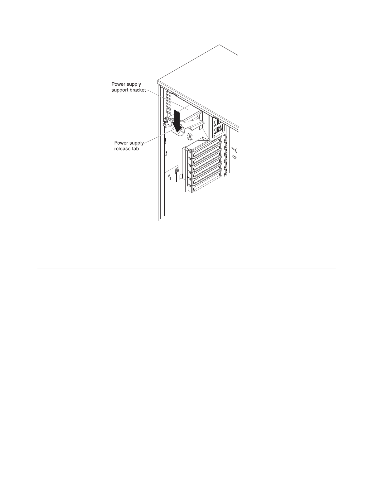
5. Install the left-side cover (see “Replacing the left-side cover” on page 101).
6. Lock the left-side cover.
7. Reconnect the external cables and power cords; then, turn on the attached
devices and turn on the server.
Installing a redundant power supply
To install the redundant power, complete the following steps:
1. Read the safety information that begins on page vii and “Installation guidelines”
on page 32.
2. Remove the left-side cover (see “Removing the left-side cover” on page 36 for
more information).
Attention: To ensure proper system cooling, do not leave the cover off the
server for more than 2 minutes.
3. Slide the new power supply partially into the empty power-supply bay. Pinch the
orange release latch and push the power supply the rest of the way into the bay
until it is seated.
82 System x3400 M2 Types 7836 and 7837: Installation and User’s Guide
 Loading...