

802.11g Wireless Broadband Router
WRT-410
User’s Manual

Copyright
Copyright 2003 by PLANET Technology Corp. All rights reserved. No part of this publication may
be reproduced, transmitted, transcribed, stored in a retrieval system, or translated into any language
or computer language, in any form or by any means, electronic, mechanical, magnetic, optical,
chemical, manual or otherwise, without the prior written permission of PLANET.
PLANET makes no representations or warranties, either expressed or implied, with respect to the
contents hereof and specifically disclaims any warranties, merchantability or fitness for any particular
purpose. Any software described in this manual is sold or licensed "as is". Should the programs
prove defective following their purchase, the buyer (and not this company, its distributor, or its dealer)
assumes the entire cost of all necessary servicing, repair, and any incidental or consequential
damages resulting from any defect in the software. Further, this company reserves the right to revise
this publication and to make changes from time to time in the contents hereof without obligation to
notify any person of such revision or changes..
All brand and product names mentioned in this manual are trademarks and/or registered trademarks
of their respective holders.
Federal Communication Commission Interference Statement
This equipment has been tested and found to comply with the limits for a Class B digital device,
pursuant to Part 15 of FCC Rules. These limits are designed to provide reasonable protection
against harmful interference in a residential installation. This equipment generates, uses, and can
radiate radio frequency energy and, if not installed and used in accordance with the instructions, may
cause harmful interference to radio communications. However, there is no guarantee that
interference will not occur in a particular installation. If this equipment does cause harmful
interference to radio or television reception, which can be determined by turning the equipment off and
on, the user is encouraged to try to correct the interference by one or more of the following measures:
1. Reorient or relocate the receiving antenna.
2. Increase the separation between the equipment and receiver.
3. Connect the equipment into an outlet on a circuit different from that to which the receiver is
connected.
4. Consult the dealer or an experienced radio technician for help.
FCC Caution:
To assure continued compliance.(example-use only shielded interface cables when connecting to
computer or peripheral devices). Any changes or modifications not expressly approved by the party
responsible for compliance could void the user’s authority to operate the equipment.
This device complies with Part 15 of the FCC Rules. Operation is subject to the Following two
conditions: (1) This device may not cause harmful interference, and (2 ) this Device must accept any
interference received, including interference that may cause undesired operation.

Federal Communication Commission (FCC) Radiation Exposure
Statement
This equipment complies with FCC radiation exposure set forth for an uncontrolled environment. In
order to avoid the possibility of exceeding the FCC radio frequency exposure limits, human proximity
to the antenna shall not be less than 20 cm(8 inches) during normal operation.
R&TTE Compliance Statement
This equipment complies with all the requirements of DIRECTIVE 1999/5/CE OF THE EUROPEAN
PARLIAMENT AND THE COUNCIL OF 9 March 1999 on radio equipment and telecommunication
terminal Equipment and the mutual recognition of their conformity (R&TTE)
The R&TTE Directive repeals and replaces in the directive 98/13/EEC (Telecommunications Terminal
Equipment and Satellite Earth Station Equipment) As of April 8,2000.
Safety
This equipment is designed with the utmost care for the safety of those who install and use it. However,
special attention must be paid to the dangers of electric shock and static electricity when working with
electrical equipment. All guidelines of this and of the computer manufacture must therefore be allowed
at all times to ensure the safe use of the equipment.
Revision
User’s Manual for PLANET Wireless Broadband Router
Model: WRT-410
Rev: 1.0 (November. 2003)
Part No. EM-WRT410

TABLE OF CONTENTS
CHAPTER 1 INTRODUCTION..................................................................................................1
1.1 PACKAGE CONTENTS .........................................................................................................1
1.2 SYSTEM REQUIREMENTS....................................................................................................1
1.3 FEATURES.........................................................................................................................1
1.4 SPECIFICATION ..................................................................................................................2
1.5 WIRELESS PERFORMANCE .................................................................................................3
CHAPTER 2 HARDWARE INSTALLATION.............................................................................4
2.1 HARDWARE CONNECTION...................................................................................................4
2.2 LED INDICATORS...............................................................................................................4
CHAPTER 3 CONFIGURE THROUGH WEB BROWSER.......................................................5
3.1 MAIN.................................................................................................................................5
3.1.1 LAN & DHCP Server................................................................................................5
3.1.2 WAN.........................................................................................................................6
3.1.3 Password..................................................................................................................8
3.1.4 Time..........................................................................................................................9
3.1.5 Dynamic DNS.........................................................................................................10
3.2 WIRELESS .......................................................................................................................10
3.2.1 Basic.......................................................................................................................10
3.2.2 Authentication.........................................................................................................11
3.2.3 Advanced................................................................................................................12
3.3 STATUS ...........................................................................................................................13
3.3.1 Device Information.................................................................................................13
3.3.2 Log.........................................................................................................................14
3.3.3 Log Settings...........................................................................................................15
3.3.4 Statistic...................................................................................................................16
3.3.5 Wireless..................................................................................................................17
3.4 ROUTING.........................................................................................................................17
3.4.1 Static.......................................................................................................................17
3.4.2 Dynamic.................................................................................................................18
3.4.3 Routing Table.........................................................................................................19
3.5 ACCESS...........................................................................................................................20
3.5.1 Filters......................................................................................................................20
3.5.2 Virtual Server..........................................................................................................23
3.5.3 Special AP..............................................................................................................24
3.5.4 DMZ........................................................................................................................25

3.5.5 Firewall Rule...........................................................................................................25
3.6 MANAGEMENT .................................................................................................................26
3.6.1 SNMP.....................................................................................................................26
3.6.2 Remote Management.............................................................................................27
3.7 TOOLS.............................................................................................................................28
3.7.1 Restart....................................................................................................................28
3.7.2 Settings..................................................................................................................28
3.7.3 Firmware................................................................................................................29
3.7.4 Ping Test.................................................................................................................29
3.8 WIZARD...........................................................................................................................30
CHAPTER 4 802.1X AUTHENTICATION SETUP..................................................................31
4.1 802.1X INFRASTRUCTURE................................................................................................31
4.2 RADIUS SERVER SETUP.................................................................................................32
4.2.1 Required Services..................................................................................................32
4.2.2 Setup Procedure....................................................................................................32
4.3 AUTHENTICATOR SETUP ...................................................................................................46
4.4 WIRELESS CLIENT SETUP.................................................................................................47
4.4.1 EAP-MD5 Authentication........................................................................................47
4.4.2 EAP-TLS Authentication.........................................................................................50
CHAPTER 5 TROUBLESHOOTING.......................................................................................58
5.1 FREQUENTLY ASKED QUESTIONS......................................................................................58
5.2 GLOSSARY ......................................................................................................................59

If any of the above items are missing, contact your supplier as soon as
Chapter 1 Introduction
Thank you for purchasing WRT-410. This device features the latest innovation wireless technology
making the wireless networking world happened. This manual guides you on how to install and properly
use the WRT-410 in order to take full advantage of its features.
1.1 Package Contents
Make sure that you have the following items:
• One WRT-410
• One dipole antenna
• One AC Power Adapter
• One User’s Manual CD
• One Quick Installation Guide
Note:
possible.
1.2 System Requirements
Before installation, please check the following requirements with your equipment.
• Pentium Based (And Above) IBM-Compatible PC System
• CD-ROM drive
• Windows 98/ME/NT/2000/XP Operating System with TCP/IP protocol
1.3 Features
• 2.4GHz ISM band, unlicensed operation
• Strong network security with 802.1X authentication, and 64/128-bit WEP encryption
• Supports WPA (Wi-Fi Protected Access) for both 802.1x and WPA-PSK
• Dual-standard capability: 802.11g and 802.11b compliant
• Super G mode efficiently raises the data transfer rate up to 108Mbps
• Supports DHCP server
• Web Configuration provide a user friendly interface for the user to configure through web
browser
• Support MAC Filter
• Build-in 4 -port switch
• Provides Setup Wizard for the user to configure easily in the first time
- 1 -

Data Encryption
1.4 Specification
Standards IEEE 802.11b, IEEE 802.11g
Signal Type DSSS (Direct Sequence Spread Spectrum)
Modulation BPSK / QPSK / CCK / OFDM
Port
Antenna One Detachable Dipole Antenna
Antenna Gain
Output Power
Sensitivity
WAN: 10/100Base-TX (RJ-45) * 1
LAN: 10/100Base-TX (RJ-45) * 4
2dBi
17dBm
11 Mbps (CCK): -82dBm
802.11b
802.11g
5.5 Mbps (QPSK): - 86dBm
1, 2 Mbps (BPSK): - 90dBm
(typically @PER < 8% packet size 1024 and @25ºC + 5ºC)
54 Mbps: -72dBm
48 Mbps: - 72dBm
36 Mbps: -76dBm
24 Mbps: -79dBm
18 Mbps: -82dBm
12 Mbps: -86dBm
9 Mbps: -89dBm
6 Mbps: -90dBm
(typically @PER < 8% packet size 1024 and @25ºC + 5ºC)
64/128-bit WEP encryption
Frequency band 2.4 GHz ~2.484GHz
FCC: 11 Channels (US, Canada)
Channel
Data Rate
Environment
Dimension 200 x 115 x 31mm (W x D x H)
Power Supply 5V, 2.5A
ETSI: 13 Channels (Europe)
TELEC: 14 Channels (Japan)
Super G mode Up to 108Mbps
802.11g Up to 54Mbps (6/9/12/18/24/36/48/54)
802.11b Up to 11Mbps (1/2/5.5/11)
Operating temperature: 0 ~ 55°C
Operating humidity: 5 ~ 95%(non-condensing)
Storage temperature: -20 ~ 70°C
Storage humidity: 0 ~ 95%(non-condensing)
- 2 -

1.5 Wireless Performance
The following information will help you utilizing the wireless performance, and operating coverage of
WRT-410.
1. Site selection
To avoid interferences, please locate WRT-410 and wireless clients away from transformers,
microwave ovens, heavy-duty motors, refrigerators, fluorescent lights, and other industrial
equipments. Keep the number of walls, or ceilings between AP and clients as few as possible;
otherwise the signal strength may be seriously reduced. Place WRT-410 in open space or add
additional WAP-4000 as needed to improve the coverage.
2. Environmental factors
The wireless network is easily affected by many environmental factors. Every environment is
unique with different obstacles, construction materials, weather, etc. It is hard to determine the
exact operating range of WRT-410 in a specific location without testing.
3. Antenna adjustment
The bundled antenna of WRT-410 is adjustable. Firstly install the antenna pointing straight up, then
smoothly adjust it if the radio signal strength is poor. But the signal reception is definitely weak in
some certain areas, such as location right down the antenna.
Moreover, the original antenna of WRT-410 can be replaced with other external antennas to extend
the coverage. Please check the specification of the antenna you want to use, and make sure it can
be used on WRT-410.
4. WLAN type
If WRT-410 is installed in an 802.11b and 802.11g mixed WLAN, its performance will reduced
significantly. Because every 802.11g OFDM packet needs to be preceded by an RTS-CTS or CTS
packet exchange that can be recognized by legacy 802.11b devices. This additional overhead
lowers the speed. If there are no 802.11b devices connected, or if connections to all 802.11b
devices are denied so that WRT-410 can operate in 11g-only mode, then its data rate should
actually 54Mbps and 108Mbps in Super G mode.
- 3 -
0. Otherwise, the product may be
0 to default settings, press and hold the Reset button over 5
Link is established
Packet
Link is established
Packet
Link is established
Green
Link is established
Chapter 2 Hardware Installation
Before you proceed with the installation, it is necessary that you have enough information about the
WRT-410.
2.1 Hardware Connection
1. Locate an optimum location for the WRT-410. The best place for your WRT-410 is usually at
the center of your wireless network, with line of sight to all of your mobile stations.
2. Adjust the antennas of WRT-410. Try to adjust them to a position that can best cover your
wireless network. The antenna’s position will enhance the receiving sensitivity.
3. Connect RJ-45 cable to WRT-410 LAN port. Connect one of the LAN ports on WRT-410 to your
LAN switch/hub with a RJ-45 cable.
4. Connect RJ-45 cable to WRT-410 WAN port. Connect ADSL/Cable Modem to the WAN port on
WRT-410. Use the cable supplied with your modem. If no cable was supplied with your modem,
please use a RJ-45 Ethernet cable
5. Plug in power adapter and connect to power source. After power on, WRT-410 will start to
operate.
Note: ONLY use the power adapter supplied with the WRT-41
damaged.
Note: If you want to reset WRT-41
seconds. And then wait for 10 seconds for WRT-410 restart.
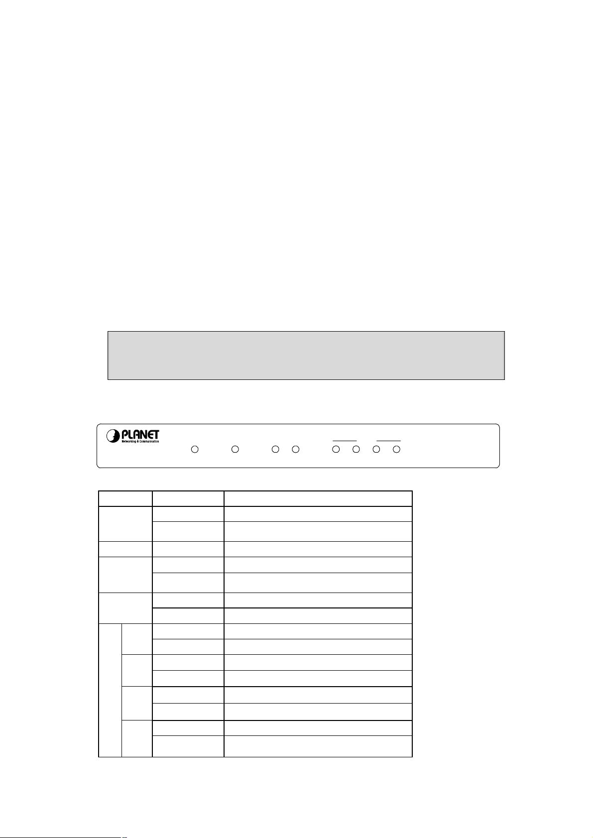
2.2 LED Indicators
WRT-410
LED STATE MEANING
Green Device power on PWR
Off
STATUS Green Indicates a connection error
Green WAN link status is on WAN
Blinking Green
Green WLAN link status is on WLAN
Blinking Green WLAN activity
LAN
Green
Blinking Green
Green
2
Blinking Green
Green
STATUSPWRWANWLAN1234
Device power off
WAN activity
1
s are transmitting or receiving
s are transmitting or receiving
3
LAN
802.11g
Wireless Router
Blinking Green Packets are transmitting or receiving
4
Blinking Green Packets are transmitting or receiving
- 4 -
Chapter 3 Configure through Web Browser
Web configuration provides a user-friendly graphical user interface (web pages) to manage your
WRT-410. A WRT-410 with an assigned IP address will allows you to monitor and configure via web
browser (e.g., MS Internet Explorer or Netscape).
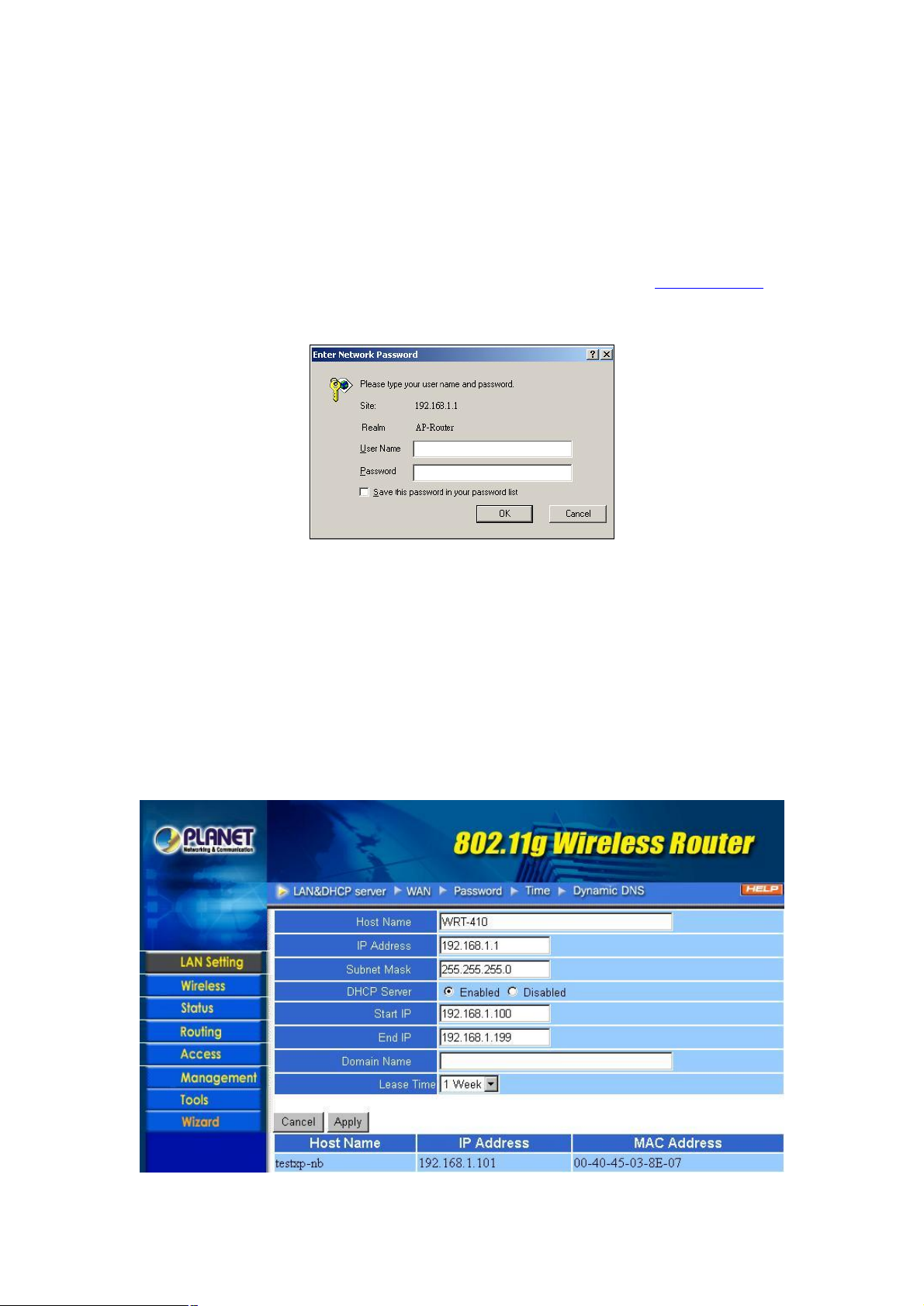
1. Open your web browser.
2. Enter the IP address of your WRT-410 in the address field (default IP address is http://192.168.1.1).
3. A User Name and Password dialog box will appear. Please enter your User Name and Password here.
Default User Name and Password are both “admin”. Click “OK”.
4. Then you will see the WRT-410 web configuration page.
5. When the first time you enter WRT-410, Setup Wizard will pop up. Please refer to our Quick
Installation Guide to use the Setup Wizard to configure. Setup Wizard will guide you through
configuration step by step.
3.1 Main
3.1.1 LAN & DHCP Server
You can configure WRT-410’s IP settings and DHCP server function in this screen. When
configuration is completed, please click “Apply” to save and restart WRT-410.
- 5 -
This page enables you to set LAN and DHCP properties, such as the host name, IP address, subnet
mask, and domain name. LAN and DHCP profiles are listed in the DHCP table at the bottom of the
screen.
Host Name: Type the host name in the text box. The host name is required by some ISPs. The default
host name is "AP-Router."
IP Address: This is the IP address of the router. The default IP address is 192.168.1.1.
Subnet Mask: Type the subnet mask for the router in the text box. The default subnet mask is
255.255.255.0.
DHCP Server: Enables the DHCP server to allow the router to automatically assign IP addresses to
devices connecting to the WLAN or LAN. DHCP is enabled by default. All DHCP client computers are
listed in the table at the bottom of the page, providing the host name, IP address, and MAC address of
the client.
Start IP: Type an IP address to serve as the start of the IP range that DHCP will use to assign IP
addresses to all LAN devices connected to the WRT-410.
End IP: Type an IP address to serve as the end of the IP range that DHCP will use to assign IP
addresses to all LAN devices connected to the WRT-410.
Domain Name: Type the local domain name of the network in the text box. This item is optional.
Lease Time: Select the proper expired duration of the IP leased by DHCP server.
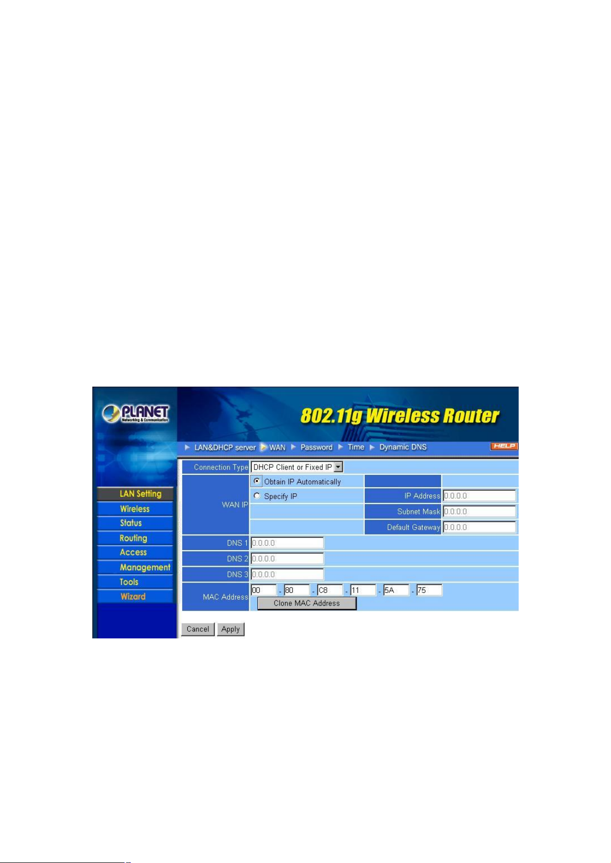
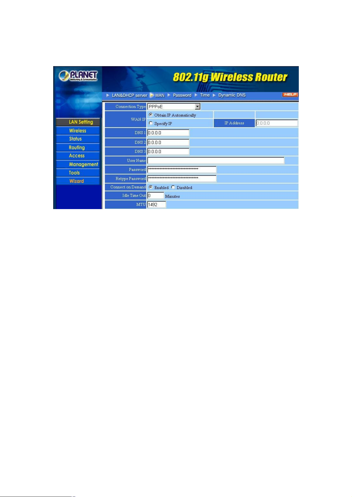
3.1.2 WAN
Please refer to your Internet connection method to select the Connection Type. And please configure
those settings per the information your ISP provides.
Connection Type: Select the connection type, DHCP client/Fixed IP, PPPoE, or PPTP from the
drop-down list.
When using DHCP client/Fixed IP, enter the following information in the fields (some information are
provided by your ISP):
WAN IP: Select whether you want to specify an IP address manually, or want DHCP to obtain an IP
address automatically. When “Specify IP” is selected, type the IP address, subnet mask, and default
gateway in the fields. Your ISP will provide you with this information.
DNS 1/2/3: Type up to three DNS numbers in the fields. Your ISP will provide you with this DNS
information.
- 6 -
MAC Address: If required by your ISP, type the MAC address for the WRT-410 WAN interface in this
field. You can also copy the MAC address of your PC’s network card to the WRT-410 WAN interface by
clicking “Clone MAC address”.
When using PPPoE, enter the following information in the fields (some information are provided by your
ISP):
WAN IP: Select whether you want the ISP to provide the IP address automatically, or whether you want
to assign a static IP address to the WRT-410 WAN interface. When “Specify IP” is selected, type the
PPPoE IP address in the field. Your ISP will provide you with this information.
DNS 1/2/3: Type up to three DNS numbers in the fields. Your ISP will provide you with this DNS
information.
User Name: Type your PPPoE user name.
Password: Type your PPPoE password.
Connect on Demand: Enables or disables the connect on demand function, which enables WRT-410 to
initiate a connection with your ISP when an Internet request is made to the WRT-410. When enabled, the
WRT-410 automatically connects to the Internet when you open your browser.
Idle Time Out: Specify the time that will elapse before the WRT-410 times out of a connection.
MTU: Type the MTU value in the field.
- 7 -
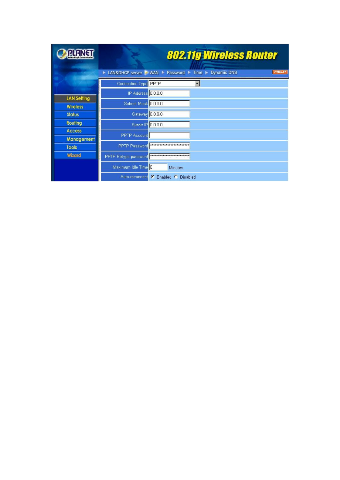
When using PPTP, enter the following information in the fields (some information are provided by your
ISP):
IP Address: Type the IP address which your ISP provides.
Subnet Mask: Type the Subnet Mask which your ISP provides.
Gateway: Type the IP address of Gateway which your ISP provides.
Server IP: Type the IP address of server which offers Internet service. Your ISP will provide you with this
information.
PPTP Account: Type your PPTP account.
PPTP Password: Type your PPTP password.
PPTP Retype password: Confirm your PPTP password again.
Maximum Idle Time: Specify the time that will elapse before the WRT-410 times out of a connection.
Auto-reconnect: If this function is enabled, WRT-410 will try to rebuild Internet connection once the link
is down.
3.1.3 Password
You can change the Administrator and User’s password in this screen. These passwords are used to gain
access to the router interface. When you login with user name “User”, you don’t have permission to
configure WRT-410.
- 8 -
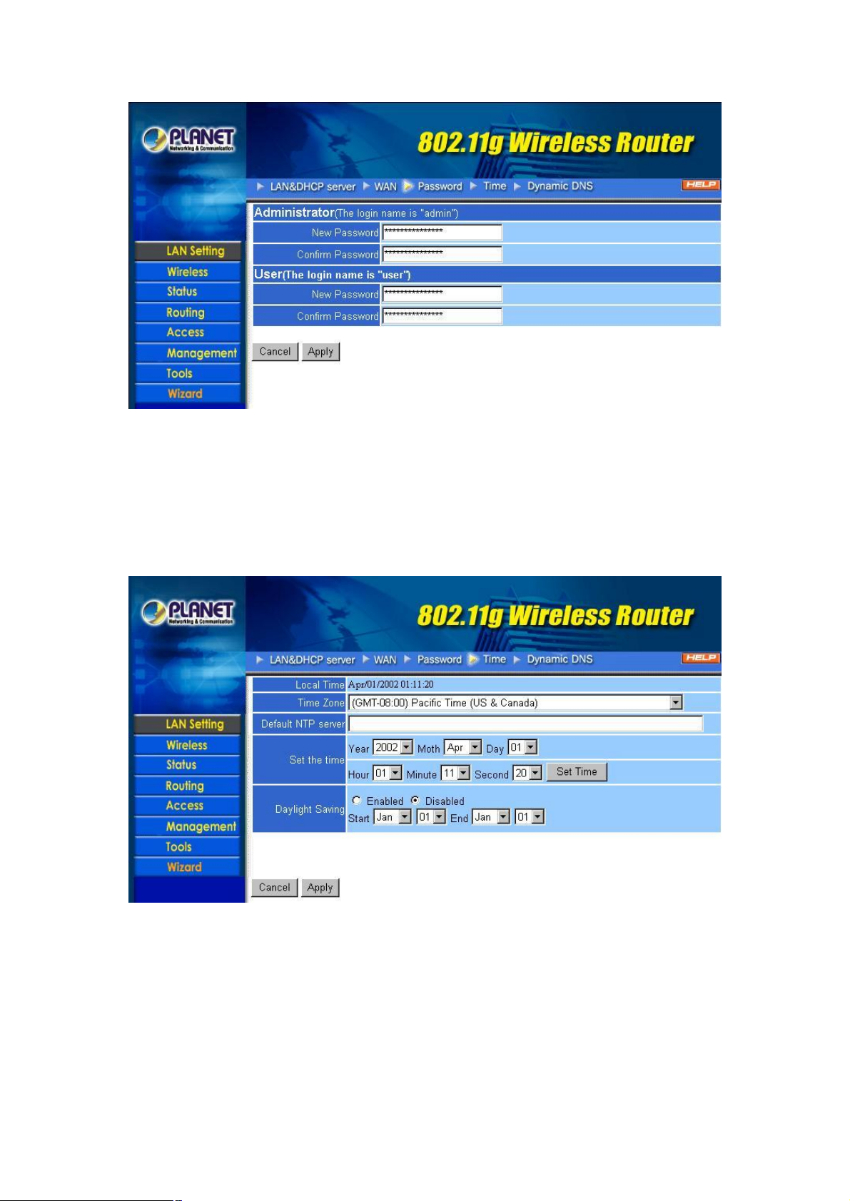
Administrator: Type the password the Administrator will use to login to the system. The password must
be typed again for confirmation.
User: Users can type a password to be used for logging in to the system. The password must be typed
again for confirmation.
3.1.4 Time
This screen enables you to set the time and date for the router's real time clock, select your time zone,
specify an NTP server, and enable or disable daylight saving.
Local Time: Displays the local time and date.
Time Zone: Select your time zone from the pull-down list.
Default NTP Server: Type the NTP server IP address in the field to enable the WRT-410 to
automatically synchronize the time with Internet NTP server.
Set the Time: Select the date and time from the pull-down lists, and click “Set Time” to set the
WRT-410's internal clock to the correct date and time.
Daylight Saving: Enables you to enable or disable daylight saving time. When enabled, select the start
and end date for daylight saving time.
- 9 -
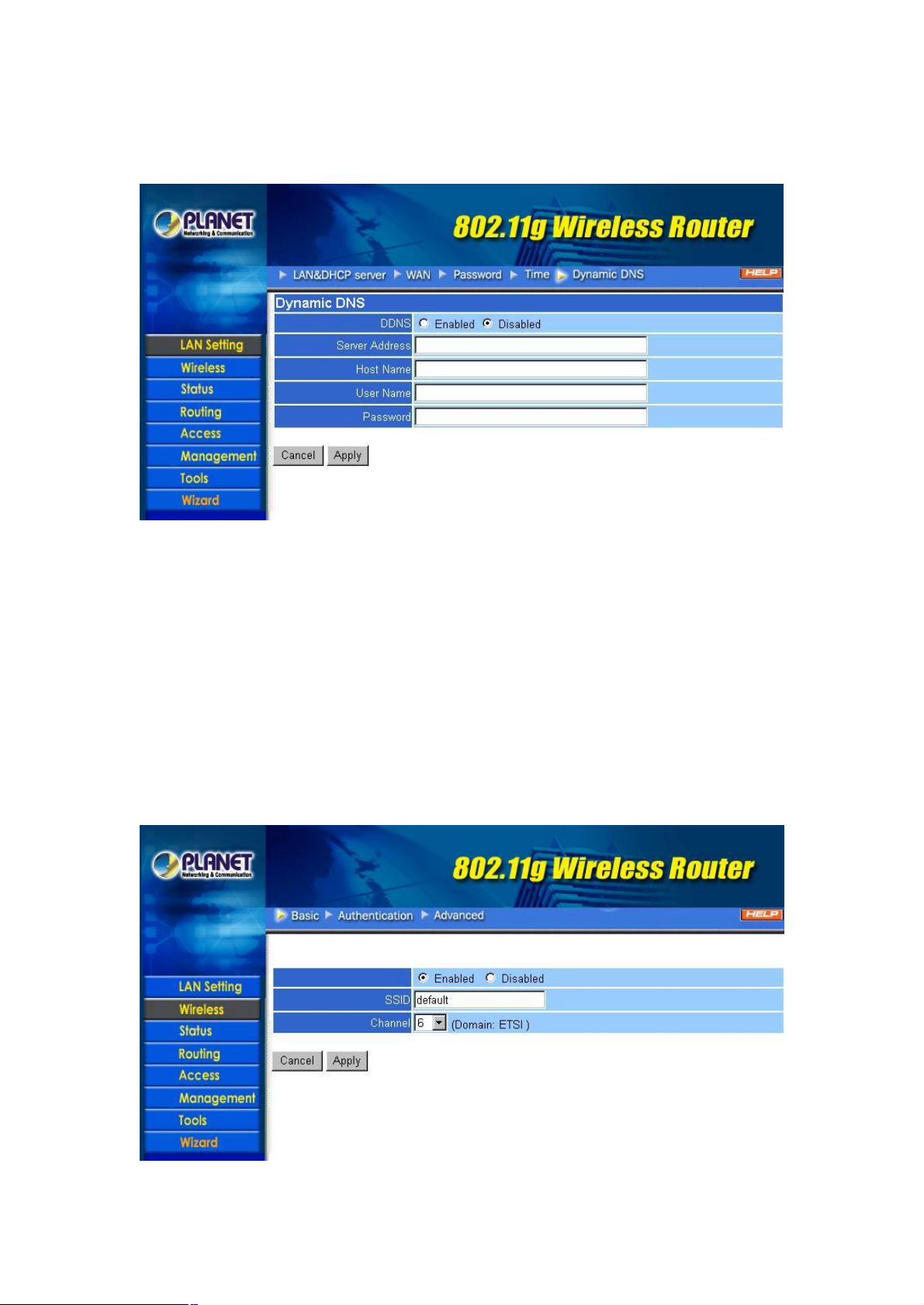
3.1.5 Dynamic DNS
You can configure WRT-410 to use DDNS service if you already have a registered DDNS account.
DDNS: You can enable or disable DDNS function here.
Server Address: Please type in the url of your DDNS service provider. Currently, WRT-410 supports
DynDNS only, thus you have to key in “www.dyndns.org” in this field.
Host Name: Enter the host name you registered to DDNS provider.
User Name: Enter the user name you registered to DDNS provider.
Password: Enter the password of your registered account.
3.2 Wireless
3.2.1 Basic
This page enables you to enable and disable the wireless LAN function, enter a SSID, and set the
channel for wireless communications.
- 10 -
Enable/Disable: Enable or disable wireless LAN via the WRT-410.
SSID: Type an SSID in the field. The SSID of any wireless device must match the SSID typed here in
order for the wireless device to access the LAN and WAN via the WRT-410.
Channel: Select a work channel for wireless communications. The channel of any wireless device must
match the channel selected here in order for the wireless device to access the LAN and WAN via the
WRT-410.
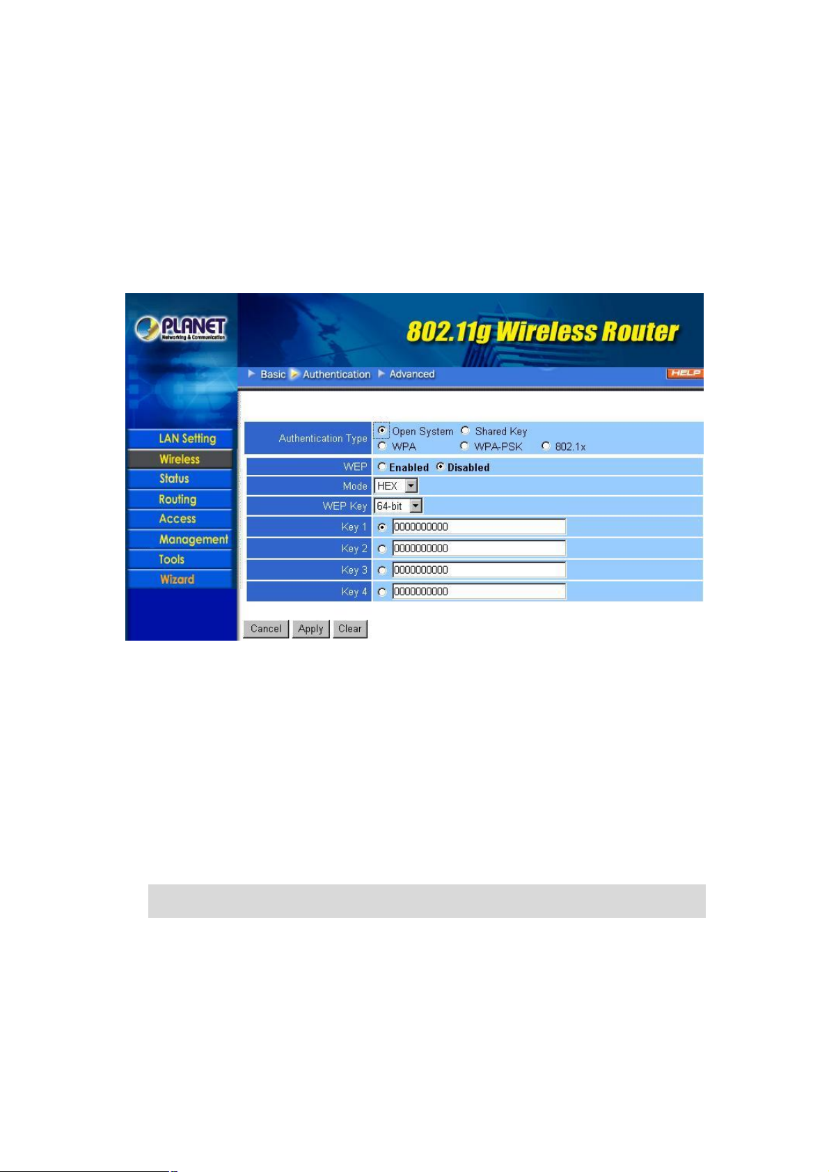
3.2.2 Authentication
This screen enables you to set authentication types and the parameters for secure wireless
communications.
Authentication Type: Select the type from the listed options. If Open System or Shared Key is selected,
the screen would appear as above.
WEP: You can enable or disable WEP function here.
Mode: Select the key code you want to use for WEP Key, HEX or ASCII. When Hex is selected, you may
enter alphanumeric characters in the range of “A-F”, “a-f” and “0-9” in the WEP Key entry field.
Alternatively, you may enter digit hexadecimal values in the range of “a-z”, “A-Z” and “0-9”.
WEP Key: Select the level of encryption you want from the drop-down list. WRT-410 supports 64, and
128-bit encryption.
Key 1 ~ Key 4: There are 4 keys available, please ensure you have enter correct number for the key
values with different Key Length and coding (Hex or ASCII) as 64bit (10 Hex digit / 5 ASCII), 128bit (26
Hex digit / 13 ASCII) or 256bit (58 Hex digit / 29 ASCII), please select one of them and enter the key you
want to use. Click “Clear” to erase key values.
Note: 128bit WEP encryption will require more system resources than 64bit encryption. Use 64-bit
encryption for better performance.
If WPA or 802.1x is selected in the Authentication Type field, the screen appears as below.
- 11 -
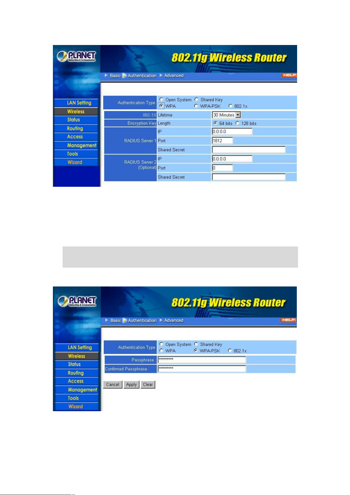
Lifetime: Select proper time interval from the drop-down list. Once the lifetime expires, the Encryption
key will be renewed by RADIUS server automatically.
Encryption Key: Select the Encryption key length to be 64-bits or 128-bits.
RADIUS Server 1: Enter the IP address, communicate port number, and shared secret key of your
primary RADIUS server.
RADIUS Server 2: Enter the IP address, communicate port number, and shared secret key of your
secondary RADIUS server.
Note: As soon as 802.1X authentication is enabled, all the wireless client stations that are connected
to the Router currently will be disconnected. The wireless clients must be configured manually
to authenticate themselves with the RADIUS server to be reconnected.
If WPA-PSK is selected, the screen appears as below. Please enter a hard-to-guess passphrase
(between 8 and 63 characters) in the field.
3.2.3 Advanced
This screen enables you to configure advanced wireless functions.
- 12 -
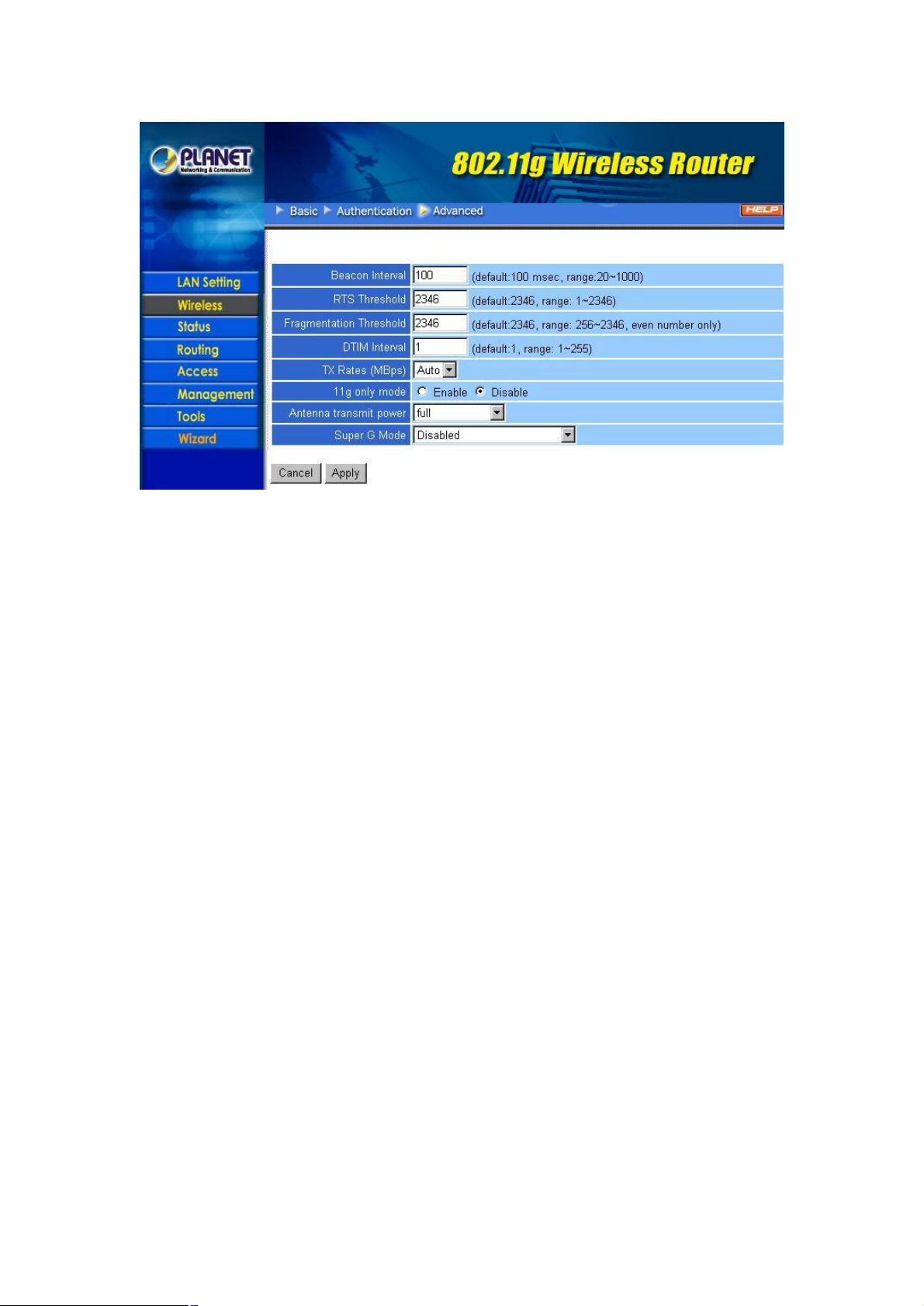
Beacon Interval: Type the beacon interval in the field. You can specify a value from 20 to 1000. The
default beacon interval is 100.
RTS Threshold: Type the RTS (Request-To-Send) threshold in the field. This value stabilizes data flow.
If data flow is irregular, choose values between 1 and 2346 until data flow is normalized.
Fragmentation Threshold: Type the fragmentation threshold in the field. If packet transfer error rates
are high, choose values between 256 and 2346 until packet transfer rates are minimized. Please note
that setting the fragmentation threshold value may diminish system performance.
DTIM Interval: Type a DTIM (Delivery Traffic Indication Message) interval in the field. You can specify a
value between 1 and 255. The default value is 1.
TX Rates (MBps): Select one of the wireless communications transfer rates, based upon the speed of
wireless adapters connected to the WLAN.
11g only mode: Enable 11g only mode will improve the performance of a 802.11g WLAN, but
non-802.11g clients cannot connect to WRT-410.
Antenna Transmit Power: You can control the transmit power of WRT-410 here. There are five options
available: full, half, quarter, eighth, and min.
Super G Mode: There are four options selectable: Disabled, Super G without Turbo, Super G with
Dynamic Turbo, and Super G with Static Turbo. When you use Super G mode, it is recommended to
enable 11g only for best performance.
3.3 Status
3.3.1 Device Information
This screen enables you to view the router LAN, wireless LAN, and WAN configuration.
- 13 -
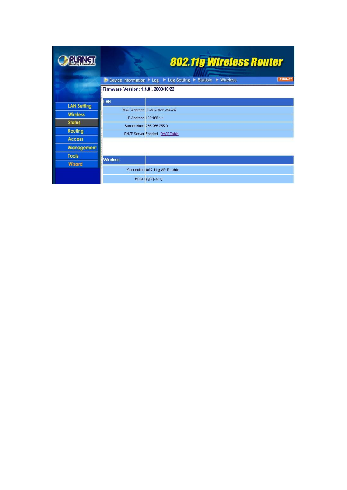
Firmware Version: Displays the latest build of the WRT-410 firmware interface. After upgrading the
firmware in Tools -> Firmware, check this to ensure that your firmware was successfully upgraded.
LAN: This field displays the WRT-410 LAN interface MAC address, IP address, subnet mask, and DHCP
server status. Click “DHCP Table” to view a list of client stations currently connected to the WRT-410
LAN interface.
Wireless: Displays the WRT-410 wireless connection information, including the WRT-410 wireless
interface MAC address, connection status, SSID status, which channel is being used and whether WEP
is enabled or not.
WAN: This field displays the WRT-410 WAN interface MAC address, DHCP client status, IP address,
subnet mask, default gateway and DNS. Click “DHCP Release” to release IP addresses get from ISP for
the WAN port. Click “DHCP Renew” to get a new IP addresses from ISP for the WAN port.
3.3.2 Log
This screen will show you a running log of system statistics, events and activities. The log displays up to
200 entries. Older entries are overwritten by new entries. You can save logs via the Log Settings option
-> “Send to”. The Log screen commands and information meaning are as follows
- 14 -
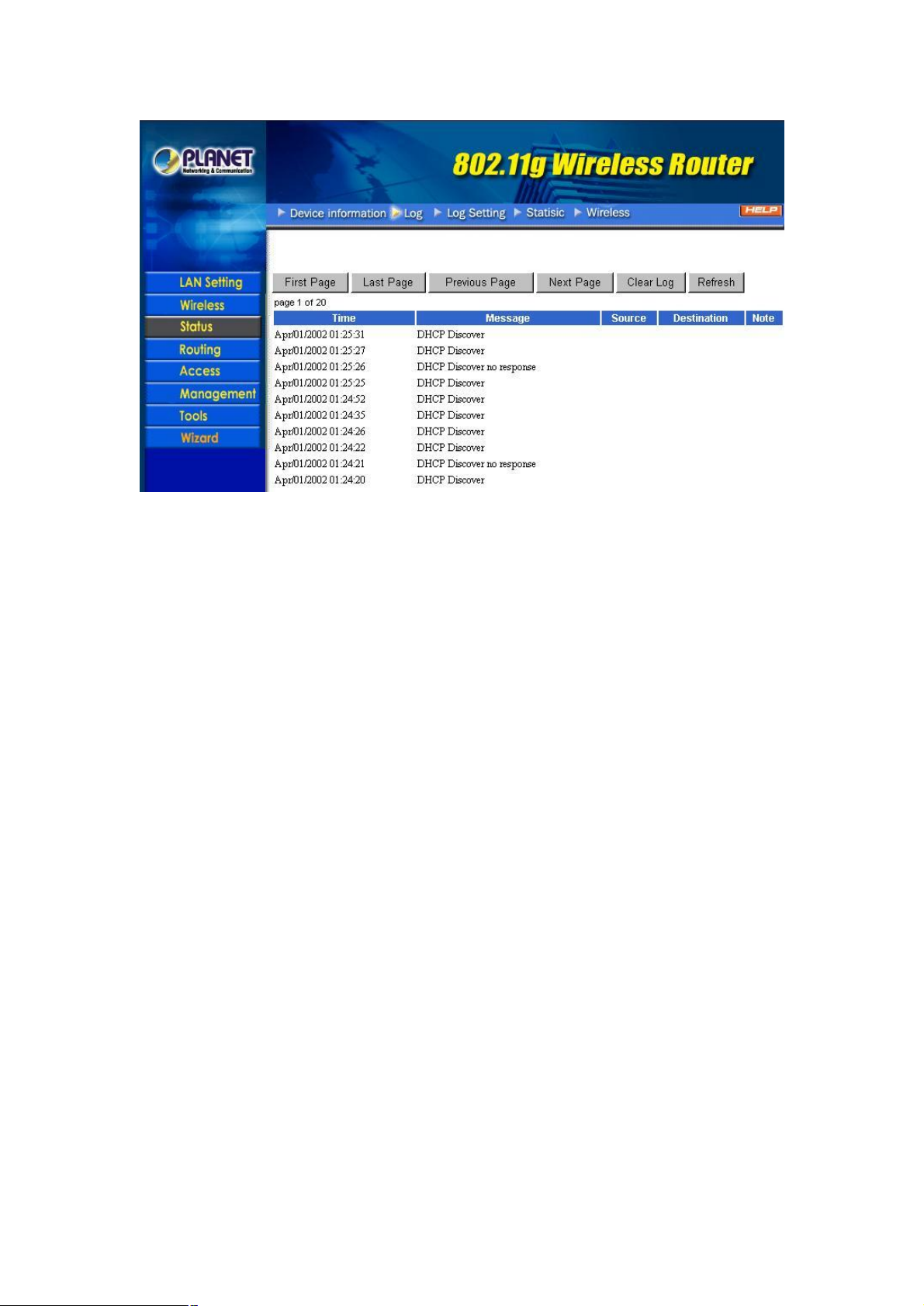
First Page: View the first page of the log message list.
Last Page: View the last page of the log message list.
Previous Page: View the page just before the current page.
Next Page: View the page just after the current page.
Clear Log: Delete the contents of the log and begin a new log.
Refresh: Renew log statistics.
Time: Displays the time and date that the log entry was created.
Message: Displays summary information about the log entry.
Source: Displays the source of the communication.
Destination: Displays the destination of the communication.
Note: Displays the IP address of the communication.
3.3.3 Log Settings
This screen allows you to set WRT-410 logging parameters.
- 15 -
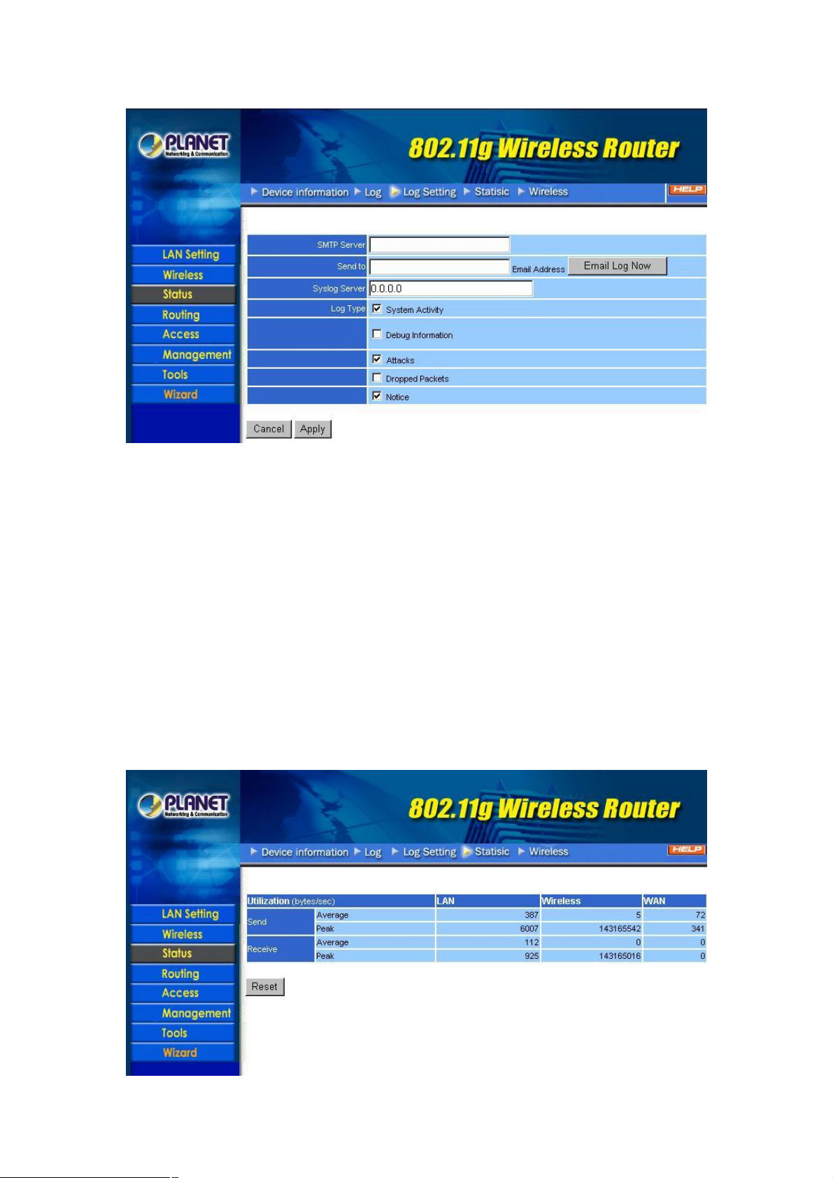
SMTP Server: Type the SMTP server address for the email that the log will be sent to in the next field.
Send to: Type an email address for the log to be sent to. Click “Email Log Now” to send the current log
immediately.
Syslog Server: Type the IP address of the Syslog Server if you want the WRT-410 to listen and receive
incoming SysLog messages.
Log Type: Select what items will be included in the log:
System Activity: Displays information related to WRT-410 operation.
Debug Information: Displays information related to errors and system malfunction.
Attacks: Displays information about any malicious activity on the network.
Dropped Packets: Displays information about packets that have not been transferred successfully.
Notice: Displays important notices by the system administrator.
3.3.4 Statistic
This screen displays a table that shows the rate of packet transmission via the WRT-410 LAN, WLAN and
WAN ports (in bytes per second).
- 16 -
Click “Reset” to erase all statistics and begin logging statistics again.
Utilization: Separates packet transmission statistics into send and receive categories. Peak indicates
the maximum packet transmission recorded since logging began, while Average indicates the average of
the total packet transmission since recording began.
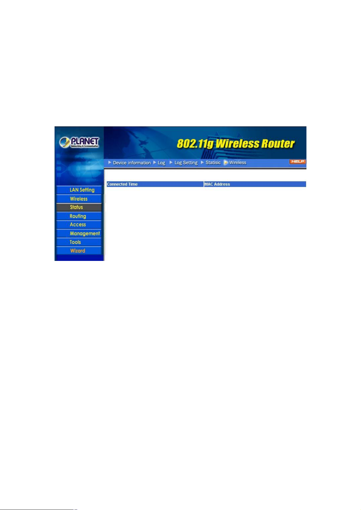
3.3.5 Wireless
This screen will show you which wireless devices that are connected to this WRT-410 via wireless
interface.
Connected Time: Displays how long the wireless device has been connected to the LAN via the
WRT-410.
MAC Address: Displays the devices wireless LAN interface MAC address.
3.4 Routing
3.4.1 Static
You can set parameters by which the WRT-410 forwards data to its destination if your network has a
static IP address.
- 17 -

Network Address: Type the static IP address your network uses to access the Internet. Your ISP or
network administrator provides you with this information.
Network Mask: Type the network (subnet) mask for your network. If you do not type a value here, the
network mask defaults to 255.255.255.255. Your ISP or network administrator provides you with this
information.
Gateway Address: Type the gateway address of your network. Your ISP or network administrator
provides you with this information.
Interface: Select the interface WAN or LAN that you will use to connect to the Internet.
Metric: Select which metric you want to apply to this configuration.
Add: Click to add a configuration to the static IP address table at the bottom of this page.
Update: Select one of the entries in the static IP address table at the bottom of the page and, after
changing parameters, click “Update” to confirm the changes.
Delete: Select one of the entries in the static IP address table at the bottom of the page and click “Delete”
to remove the entry.
New: Click “New” to clear the fields and add required information to create a new entry.
3.4.2 Dynamic
This screen allows you to set the NAT parameters.
- 18 -

NAT: Select the option to enable or disable NAT.
Transmit: Select the option to set the desired transmit parameters. Disabled, RIP 1 or RIP 2.
Receive: Select the option to set the desired transmit parameters. Disabled, RIP 1 or RIP 2.
3.4.3 Routing Table
This screen will show you the routing table of WRT-410. The routing table is a database created by the
WRT-410 that displays the network interconnection topology.
Network Address: Displays the network IP address of the connected node.
Network Mask: Displays the network (subnet) mask of the connected node.
Gateway Address: Displays the gateway address of the connected node.
Interface: Displays whether the node is connected via a WAN or LAN.
Metric: Displays the metric of the connected node.
Type: Displays whether the node has a static or dynamic IP address.
- 19 -

3.5 Access
3.5.1 Filters
This screen enables you to allow and deny user access based upon the filters you set. If MAC Filters is
selected, the screen appears as below.
MAC Filter: Enables you to allow or deny Internet access for users within the LAN based upon the MAC
address of their network interface. Click the radio button next to disable or enable the MAC filter.
Disabled: All users are allowed Internet access.
Enable: All users are allowed Internet access except those users listed in MAC table.
MAC Table: Use this section to create a table to which Internet access is denied or allowed. The user
profiles are listed in the table at the bottom of the page.
Note: When selecting items in the table at the bottom, click anywhere in the item. The line is
selected, and the fields automatically load the item's parameters, which you can edit.
Name: Type the name of the user to be denied access.
MAC Address: Type the MAC address of the user's network interface.
Add: Click to add the user to the list at the bottom of the page.
Update: Click to update information for the user, if you have changed any of the fields.
Delete: Select a user from the table at the bottom of the list and click “Delete” to remove the user profile.
Clear: Click “Clear” to erase all fields and enter new information.
If URL Blocking is selected, the screen appears as below. In the text field, enter the keyword of the url
you want to block, then click the “Add” button. The word would appear on the list immediately. If you want
to remove any existing word, just select it from the list and click “Delete” button.
- 20 -
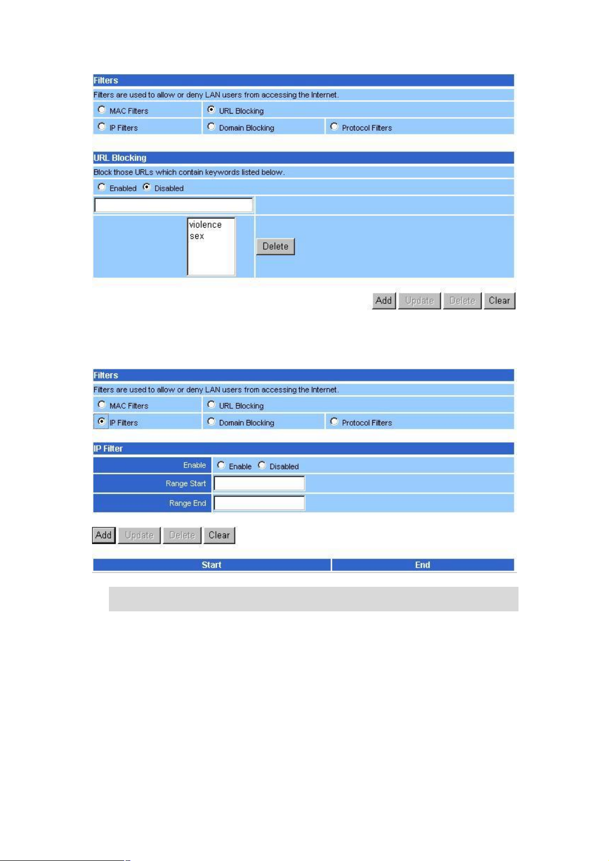
The following screen appears once you select IP Filters. It enables you to define a minimum and
maximum IP address range filter; all IP addresses falling in the range are not allowed Internet access.
The IP filter profiles are listed in the table at the bottom of the page.
Note: When selecting items in the table at the bottom, click anywhere in the item. The line is
selected, and the fields automatically load the item's parameters, which you can edit.
Enable: Click to enable or disable the IP address filter.
Range Start: Type the minimum address for the IP range. IP addresses falling between this value and
the Range End are not allowed to access the Internet.
Range End: Type the minimum address for the IP range. IP addresses falling between this value and the
Range Start are not allowed to access the Internet.
Add: Click to add the IP range to the table at the bottom of the screen.
Update: Click to update information for the range if you have selected a list item and have made
changes.
Delete: Select a list item and click “Delete” to remove the item from the list.
Clear: Click “Clear” to erase all fields and enter new information.
- 21 -
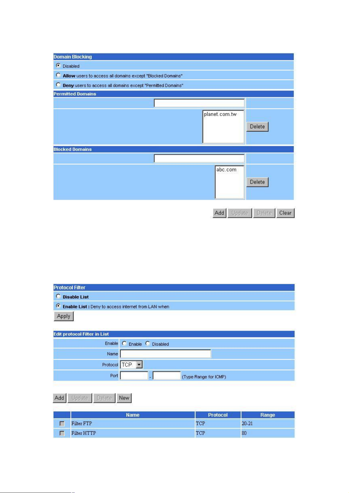
Select Domain Blocking, and the following screen appear.
Domain Blocking: There are three options in this field. Select the proper setting according to your
demand.
Permitted Domains: Enter the domain name in the text field, and click “Add” button to add it to the list.
Blocked Domains: Enter the domain name in the text field, and click “Add” button to add it to the list.
Select Protocol Filter, the screen appears as below. It enables you to allow or deny access based upon a
communications protocol list you create. The protocol filter profiles are listed in the table at the bottom of
the page.
- 22 -

Note: When selecting items in the table at the bottom, click anywhere in the item. The line is
selected, and the fields automatically load the item's parameters, which you can edit.
Protocol Filter: Enables you to allow or deny Internet access to users based upon the communications
protocol of the origin. Click the radio button next to Disabled to disable the protocol filter.
Disable List: Select this option to disable Protocol Filter.
Enable List: All protocols in the list are not allowed to connect to the Internet via the LAN. (Create list
items in section under Add Protocol Filter.)
Edit Protocol Filter in List: Use this section to create a profile for the protocol you want to deny Internet
access to.
Enable: Click to enable or disable the protocol filter.
Name: Type a descriptive name for the protocol filter.
Protocol: Select the protocol (TCP, UDP or ICMP) you want to allows/deny Internet access to from the
pull-down list.
Port Range: If you are creating a profile for ICMP, type a minimum and maximum port range in the two
fields.
Add: Click to add the protocol filter to the list at the bottom of the page.
Update: Click to update information for the protocol filter, if you have changed any of the fields.
Delete: Select a filter profile from the table at the bottom of the list and click “Delete” to remove the
profile.
New: Click “New” to erase all fields and enter new information.
3.5.2 Virtual Server
This screen enables you to create a virtual server via the WRT-410. If the WRT-410 is set as a virtual
server, remote users requesting Web or FTP services through the WAN are directed to local servers in
the LAN. The WRT-410 redirects the request via the protocol and port numbers to the correct LAN server.
The Virtual Sever profiles are listed in the table at the bottom of the page.
Enable: Click to enable or disable the virtual server.
Name: Type a descriptive name for the virtual server.
Protocol: Select the protocol (TCP or UDP) you want to use for the virtual server.
Private Port: Type the port number of the computer on the LAN that is being used to act as a virtual
server.
- 23 -

Public Port: Type the port number on the WAN that will be used to provide access to the virtual server.
LAN Server: Type the LAN IP address that will be assigned to the virtual server.
Add: Click to add the virtual server to the table at the bottom of the screen.
Update: Click to update information for the virtual server if you have selected a list item and have made
changes.
Delete: Select a list item and click “Delete” to remove the item from the list.
Clear: Click “Clear” to erase all fields and enter new information.
3.5.3 Special AP
This screen allows you to specify special applications, such as games, that require multiple connections
that are inhibited by NAT.
The special applications profiles are listed in the table at the bottom of the page.
Enable: Click to enable or disable the application profile. When enabled, users will be able to connect to
the application via the WRT-410 WAN connection. Click Disabled on a profile to prevent users from
accessing the application on the WAN.
Name: Type a descriptive name for the application.
Trigger: Defines the outgoing communication that determines whether the user has legitimate access to
the application.
Protocol: Select the protocol (TCP, UDP or ICMP) that can be used to access the application.
Port Range: Type the port range that can be used to access the application in the fields.
Incoming: Defines which incoming communications users are permitted to connect with.
Protocol: Select the protocol (TCP, UDP or ICMP) that can be used by the incoming communication.
Port: Type the port number that can be used for the incoming communication.
Add: Click to add the special application profile to the table at the bottom of the screen.
Update: Click to update information for the special application if you have selected a list item and have
made changes.
Delete: Select a list item and click “Delete” to remove the item from the list.
Clear: Click “Clear” to erase all fields and enter new information.
- 24 -

3.5.4 DMZ
This screen enables you to create a DMZ for those computers that cannot access Internet applications
properly through the WRT-410 and associated security settings.
Enable: Click to enable or disable the DMZ.
DMZ Host IP: Type a host IP address for the DMZ. The computer with this IP address acts as a DMZ
host with unlimited Internet access.
Apply: Click to save the settings.
Note: Any clients added to the DMZ exposes the clients to security risks such as viruses and
unauthorized access.
3.5.5 Firewall Rule
This screen enables you to set up the firewall. The WRT-410 provides basic firewall functions, by filtering
all the packets that enter the WRT-410 using a set of rules. The rules are in an order sequence list the
lower the rule number, the higher the priority the rule has.
The rule profiles are listed in the table at the bottom of the page.
- 25 -

Enable: Click to enable or disable the firewall rule profile.
Name: Type a descriptive name for the firewall rule profile.
Action: Select whether to allow or deny packets that conform to the rule.
Source: Defines the source of the incoming packet that the rule is applied to.
Interface: Select which interface (WAN or LAN) the rule is applied to.
IP Range Start: Type the start IP address that the rule is applied to.
IP Range End: Type the end IP address that the rule is applied to.
Destination: Defines the destination of the incoming packet that the rule is applied to.
Interface: Select which interface (WAN or LAN) the rule is applied to.
IP Range Start: Type the start IP address that the rule is applied to.
IP Range End: Type the end IP address that the rule is applied to.
Protocol: Select the protocol (TCP, UDP or ICMP) of the destination.
Port Range: Select the port range.
Add: Click to add the rule profile to the table at the bottom of the screen.
Update: Click to update information for the rule if you have selected a list item and changed.
Delete: Select a list item and click “Delete” to remove the item from the list.
New: Click “New” to erase all fields and enter new information.
Priority Up: Select a rule from the list and click “Priority” Up to increase the priority of the rule.
Priority Down: Select a rule from the list and click “Priority Down” to decrease the priority of the rule.
Update Priority: After increasing or decreasing the priority of a rule, click “Update Priority” to save the
changes.
3.6 Management
3.6.1 SNMP
This screen allows you to configure SNMP.
- 26 -

Enabled/Disabled: Click to enable or disable SNMP. By default is disabled.
System Name: Displays the name given to the WRT-410.
System Location: Displays the location of the WRT-410 (normally, the DNS name).
System Contact: Displays the contact information for the person responsible for the WRT-410.
Community: SNMP system name for exchanging SNMP community messages. The name can be used
to limit SNMP messages passing through the network. The default name is “public”.
Trap Receiver: Type the name of the destination PC that will receive trap messages.
3.6.2 Remote Management
This screen enables you to set up remote management. Using remote management, the WRT-410 can
be configured through the WAN via a Web browser. A user name and password are required to perform
remote management.
HTTP: Enables you to set up HTTP access for remote management.
- 27 -

Enable: Click to enable or disable HTTP access for remote management.
Remote IP Range: Type the range of IP addresses that can be used for remote access.
Allows to Ping WAN Port: This function allows remote users to ping WRT-410 WAN port IP address.
Enable: Click to enable or disable WAN port pinged function.
Remote IP Range: Type the range of IP addresses that can ping from remote locations.
UPNP Enable: Click to enable or disable UPNP.
Gaming mode: Click to enable or disable Game mode.
PPTP: Click to enable or disable PPTP passthrough.
IPSec: Click to enable or disable IPSec passthrough.
3.7 Tools
3.7.1 Restart
Click Restart to restart the system in the event the system is not performing correctly.
3.7.2 Settings
This screen allows you to save settings as a profile and load profiles for different circumstances. You can
also load the factory default settings, and run a setup wizard to configure the WRT-410 and WRT-410
interface.
- 28 -
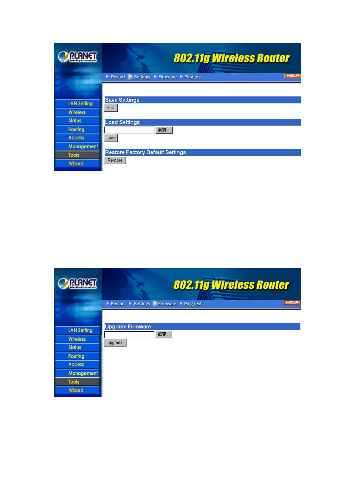
Save Settings: Click to save the current configuration as a profile that you can load when necessary.
Load Settings: Click “Browse” and go to the location of a stored profile. Click Load to load the profile's
settings.
Restore Factory Default Settings: Click to restore the default settings. All configuration changes you
have made will be lost.
3.7.3 Firmware
You can upgrade your WRT-410 with new firmware in this screen. Please follow these instructions:
1. Download the latest firmware from PLANET's website, and save it to your disk.
2. Click “Browse” and find out the location of the downloaded file.
3. Select the file and click “Upgrade” to update WRT-410 to the latest firmware.
3.7.4 Ping Test
You can ping an IP address or host which is present on the Internet. Type the IP address or host name in
the field and click Ping.
- 29 -

3.8 Wizard
The setup wizard enables you to configure the WRT-410 quickly and conveniently. Click “Wizard”
button, the window below will appear. Please click “Next>” and follow the steps to configure WRT-410.
You are prompted to select a password. Type a password in the text box, and then type it again for
verification. Click Next.
Select your time zone from the drop-down list. Click Next.
Type the LAN IP address in the text box. The default IP address is 192.168.1.1.
Type the subnet mask in the text box.
Enable DHCP Server if you want DHCP to automatically assign IP addresses. Type a beginning IP
address and an end IP address for the DHCP server to use in assigning IP addresses.
Click Next. Select how the router will set up the Internet connection. If you have enabled DHCP server,
choose "Obtain IP automatically (DHCP client)" to have the router assign IP addresses automatically.
Click to enable or disable wireless LAN. If you enable the wireless LAN, type the SSID in the text box and
select a communications channel. The SSID and channel must be the same as wireless devices
attempting communication to the router.
Click Next. You are prompted to restart save the settings and restart the router interface. Click Restart to
complete the wizard.
- 30 -

Chapter 4 802.1X Authentication Setup
4.1 802.1X Infrastructure
An 802.1X Infrastructure is composed of three major components: Authenticator, Authentication server,
and Supplicant.
Authentication server: An entity that provides an authentication service to an authenticator. This
service determines, from the credentials provided by the supplicant, whether the supplicant is authorized
to access the services provided by the authenticator.
Authenticator: An entity at one end of a point-to-point LAN segment that facilitates authentication of the
entity attached to the other end of that link.
Supplicant: An entity at one end of a point-to-point LAN segment that is being authenticated by an
authenticator attached to the other end of that link.
In the following sections, we will guide you to build an 802.1X Infrastructure step by step. The instructions
are divided into three parts:
RADIUS Server Setup: Microsoft Windows 2000 server.
Authenticator Setup: WRT-410.
Wireless Client Setup: Microsoft Windows XP.
The above graph shows the network topology of the solution we are going to introduce. As illustrated, a
group of wireless clients is trying to build a wireless network with WRT-410 in order to have access to
both Internet and Intranet. With 802.1X authentication, each of these wireless clients would have to be
authenticated by RADIUS server. If the client is authorized, WRT-410 would be notified to open up a
communication port to be used for the client. There are 2 Extensive Authentication Protocol (EAP)
methods supported: (1) MD5 and (2) TLS.
MD5 authentication is simply a validation of existing user account and password that is stored in a
database of RADIUS server. Therefore, wireless clients will be prompted for account/password validation
to build the link. TLS authentication is a more complicated authentication, which is using certificate that is
issued by RADIUS server for authentication. TLS authentication is a more secure authentication, since
not only RADIUS server authenticates the wireless client, but also the client can validate RADIUS server
by the certificate that it issues. The TLS authentication request from wireless clients and reply by Radius
Server and WRT-410 can be briefed as follows:
1. The client sends an EAP start message to WRT-410.
2. WRT-410 replies with an EAP Request ID message.
3. The client sends its Network Access Identifier (NAI) – its user name – to WRT-410 in an EAP
Respond message.
4. WRT-410 forwards the NAI to the RADIUS server with a RADIUS Access Request message.
5. The RADIUS server responds to the client with its digital certificate.
- 31 -

6. The client validates the digital certificate, and replies its own digital certificate to the RADIUS server.
7. The RADIUS server validates client’s digital certificate.
8. The client and RADIUS server derive encryption keys.
9. The RADIUS server sends WRT-410 a RADIUS ACCEPT message, including the client’s WEP key.
10. WRT-410 sends the client an EAP Success message along with the broadcast key and key length,
all encrypted with the client’s WEP key.
4.2 RADIUS Server Setup
4.2.1 Required Services
After Windows 2000 server has been installed, please install Service Pack 2 also and other latest
security patch.
Furthermore, the following service components are needed:
n Active Directory (Please consult with your network administrator or an engineer who is familiar with
Windows 2000 server to install Active Directory; otherwise your system or network might be
unstable.)
n IAS (Internet Authentication Service)
n Web Server (IIS)
n Certificate Service
4.2.2 Setup Procedure
1. Login into Windows 2000 Server as Administrator, or account that has Administrator authority.
2. Go to Start > Control Panel, and double-click “Add or Remove Programs”.
3. Click on “Add/Remove Windows components”.
4. Check “Certificate Services”, and click “Next” to continue.
5. Select “Enterprise root CA”, and click “Next” to continue.
- 32 -

6. Enter the information that you want for your Certificate Service, and click “Next” to continue.
7. Go to Start > Program > Administrative Tools > Certificate Authority.
8. Right-click on the “Policy Setting”, select “new”.
9. Select “Certificate to Issue”.
10. Select “Authenticated Session” and “Smartcard Logon” by holding down to the Ctrl key, and click
“OK” to continue.
- 33 -
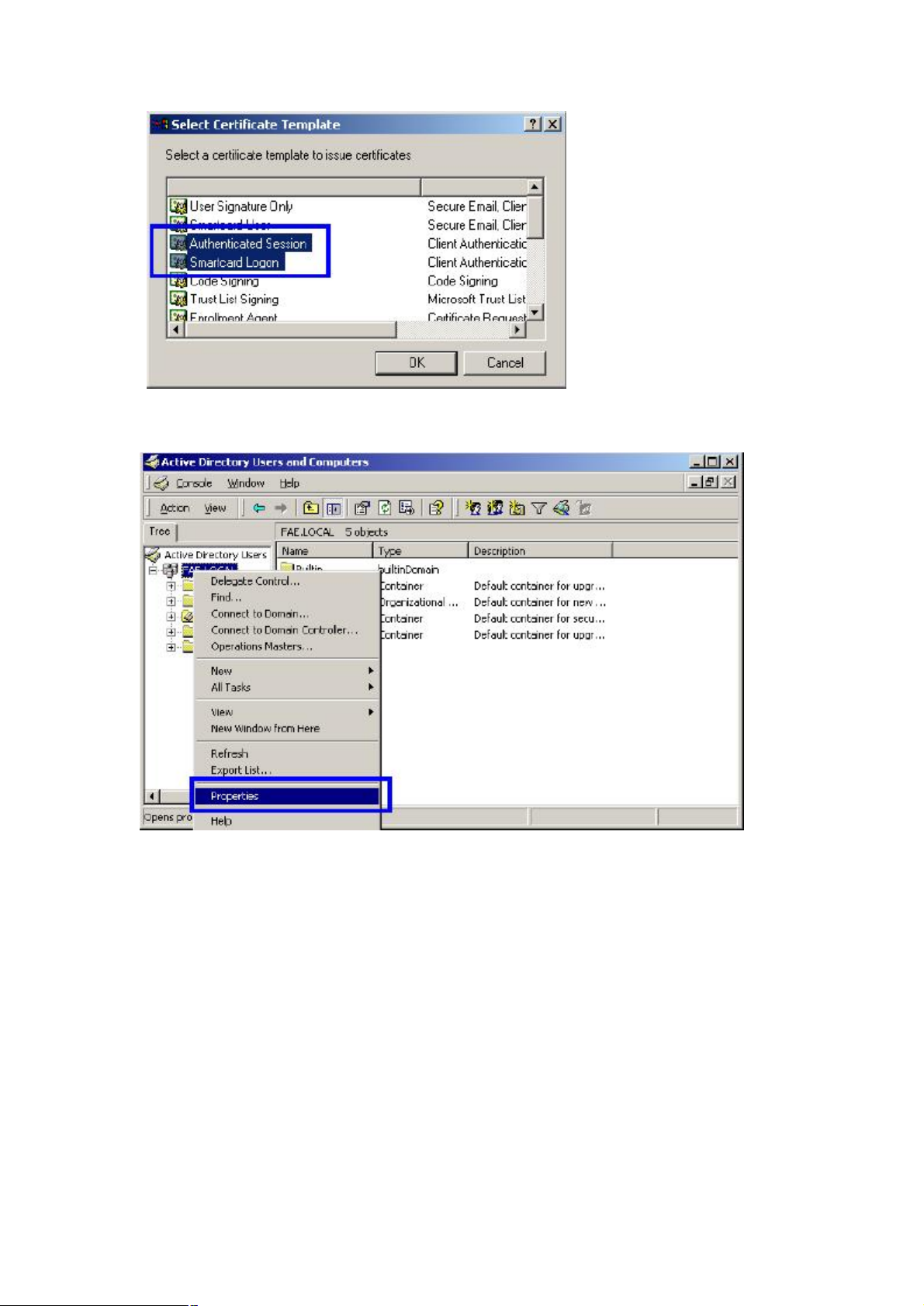
11. Go to Start > Program > Administrative Tools > Active Directory Users and Computers.
12. Right-click on domain, and select ”Properties” to continue.
13. Select “Group Policy” tab and click “Properties” to continue.
- 34 -

14. Go to “Computer Configuration” > “Security Settings” > “Public Key Policies”
15. Right-click “Automatic Certificate Request Setting”, and select “New”
16. Click “Automatic Certificate Request ...”
- 35 -

17. The Automatic Certificate Request Setup Wizard will guide you through the Automatic Certificate
Request setup, simply click “Next” through to the last step.
18. Click “Finish” to complete the Automatic Certificate Request Setup
19. Go to Start > Run, and type “command” and click “Enter” to open Command Prompt.
20. Type “secedit/refreshpolicy machine_policy” to refresh policy.
Adding Internet Authentication Service
21. Go to Start > Control Panel > Add or Remove Programs.
22. Select “Add/Remove Windows Components” from the panel on the left.
23. Select “Internet Authentication Service”, and click “OK” to install.
- 36 -
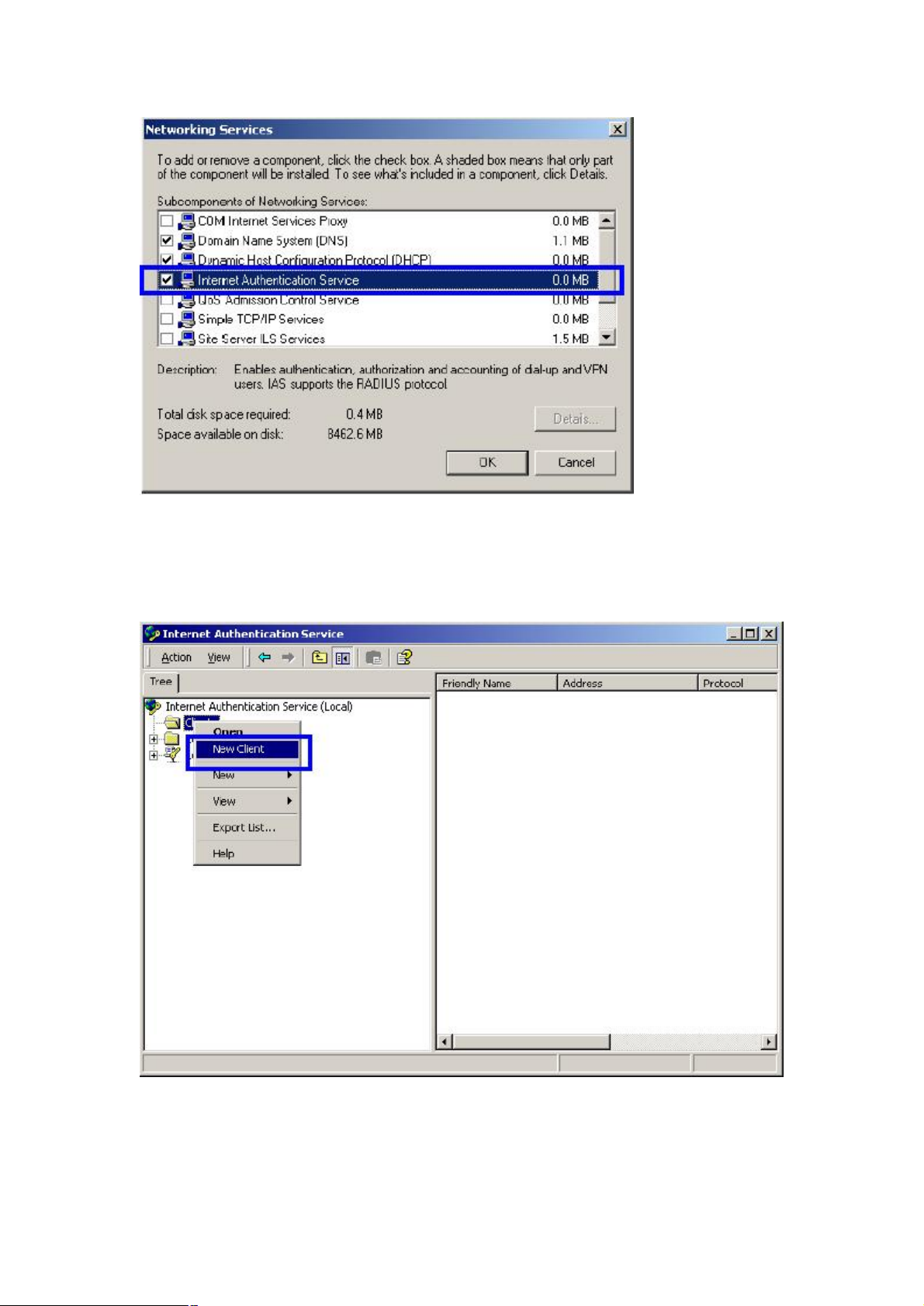
Setting Internet Authentication Service
24. Go to Start > Program > Administrative Tools > Internet Authentication Service.
25. Right-click “Client”, and select “New Client”.
26. Enter the IP address of WRT-410 in the Client address text field, a memorable name for WRT-410 in
the Client-Vendor text field, the access password used by WRT-410 in the Shared secret text field.
Re-type the password in the Confirmed shared secret text field.
27. Click “Finish”.
- 37 -

28. In the Internet Authentication Service, right-click “Remote Access Policies”
29. Select “New Remote Access Policy”.
30. Select “Day-And-Time-Restriction”, and click “Add” to continue.
- 38 -

31. Unless you want to specify the active duration for 802.1X authentication, click “OK” to accept for
having 802.1x authentication enabled at all times.
32. Select “Grant remote access permission”, and click “Next” to continue.
- 39 -

33. Click “Edit Profile”.
For TLS Authentication Setup (Steps 34 ~ 35)
34. Select “Authentication” Tab.
35. Enable “Extensible Authentication Protocol”, and select “Smart Card or other Certificate” for
TLS authentication. Click “OK”. Then go to step 38.
- 40 -
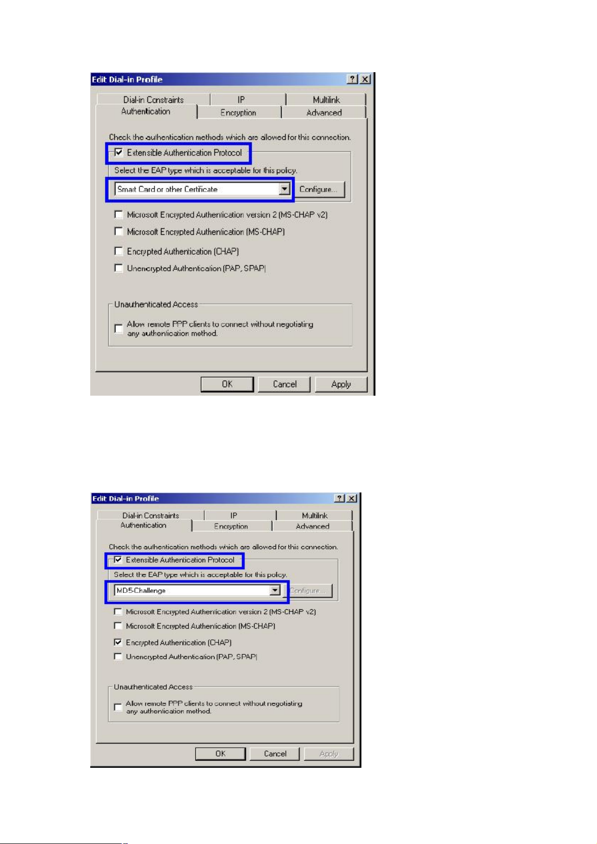
For MD5 Authentication Setup (Steps 36 ~ 37)
36. Select “Authentication” Tab.
37. Enable “Extensible Authentication Protocol”. Select “MD5-Challenge” and enable “Encrypted
Authentication (CHAP)” for MD5 authentication. Click “OK”.
- 41 -
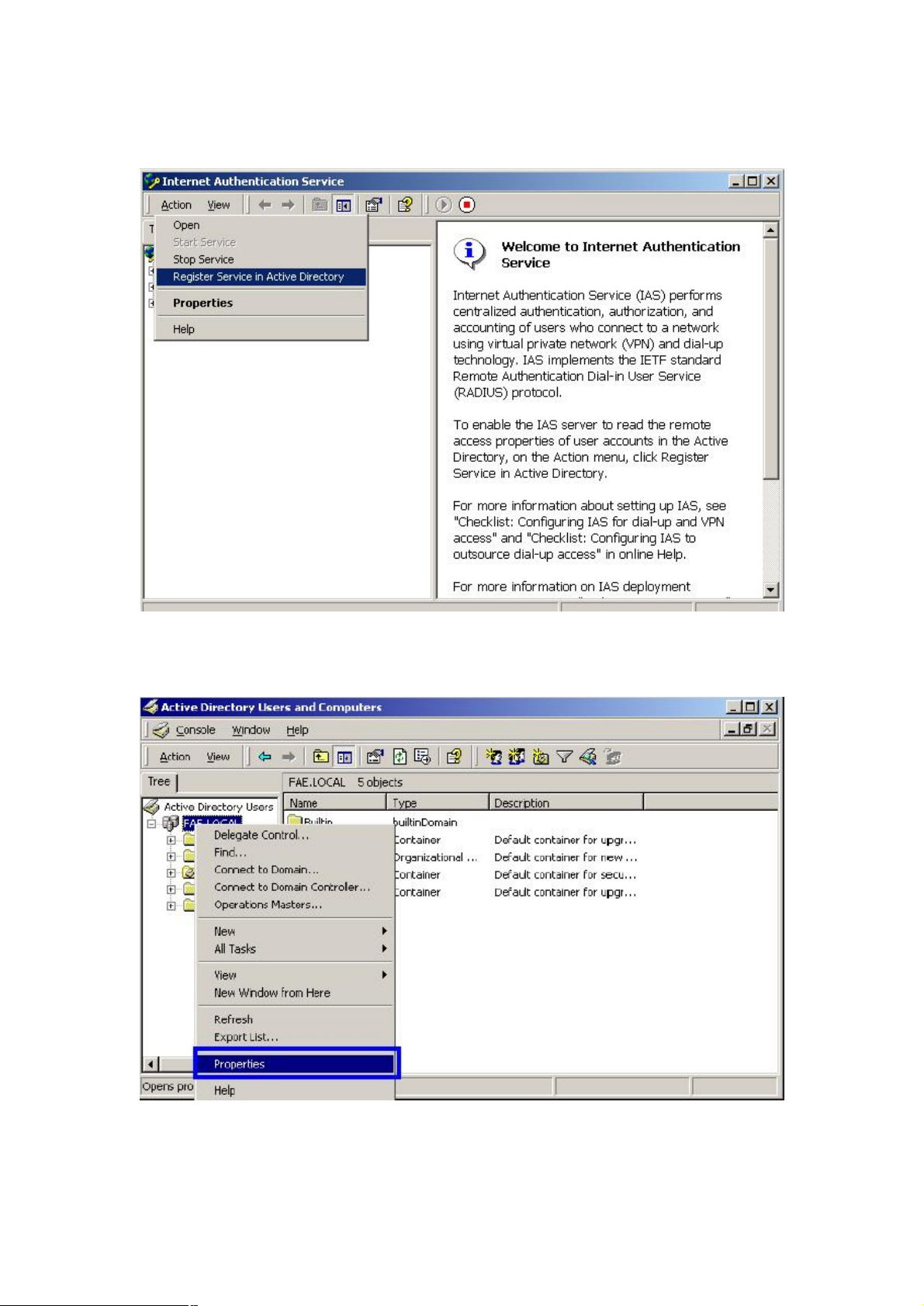
38. Select “Internet Authentication Service (Local)”, click on “Action” from top panel. Then click
“Register Service in Active Directory”.
39. Go to Start > Program > Administrative Tools > Active Directory Users and Computers.
40. Right click on the domain, and select “Properties”.
41. Select “Group Policy” tab, and click “Edit” to edit the Group Policy.
- 42 -

42. Go to “Computer Configuration” > “Windows Settings” > “Security Settings” > “Account
Policies” > “Password Policies”. Double click on “Store password using reversible encryption for
all users in the domain”.
- 43 -

43. Click “Define this policy setting”, select “Enabled”, and click “OK” to continue.
44. Go to Start > Program > Administrative Tools > Active Directory Users and Computers.
45. Go to Users. Right-click on the user that you are granting access, and select “Properties”.
46. Go to “Account” tab, and enable “Store password using reversible encryption”.
47. Click “Apply” to continue.
- 44 -

48. Go to the “Dial-in” tab, and check “Allow access” option for Remote Access Permission and “No
Call-back” for Callback Options. Then click “OK”.
- 45 -

4.3 Authenticator Setup
1. For EAP-MD5 Authentication, WEP key must be set previously. Go to Wireless>Authentication.
Enable WEP key, and enter a desired key string. You can skip this step if using EAP-TLS Authentication.
2. Click on 802.1X for detailed configuration.
3. Enable 802.1X Authentication by selecting “Enable”.
4. If EAP-MD5 is used, you can leave the settings in Encryption Key Length and Lifetime as default. If
you are using EAP-TLS authentication, set the Encryption Key Length ranging from 64 to 256 Bits and
the Lifetime from 5 Minutes to 1 Day. As soon as the lifetime expires, the Encryption Key will be renewed
by RADIUS server.
5. Enter the IP address, Port number, and Shared Secret Key used by the Primary Radius Server.
- 46 -

6. Enter the IP address, Port number, and Shared Secret Key used by the Secondary Radius Server.
7. Click “Apply”. The 802.1x settings will take effect right after WRT-410 reboots itself.
4.4 Wireless Client Setup
Windows XP is originally 802.1X support. As to other operating systems (windows 98SE, ME, 2000), an
802.1X client utility is needed. The following procedures show how to configure 802.1X Authentication
with WL-3555 in Windows XP.
Please note that if you want to change the 802.1x authentication type of a wireless client, i.e. switch to
EAP-TLS from EAP-MD5, you must remove the current existing wireless network from your preferred
connection first, and add it in again.
4.4.1 EAP-MD5 Authentication
1. Go to Start > Control Panel, double-click on “Network Connections”.
2. Right-click on the Wireless Network Connection which using WL-3555.
3. Click “Properties” to open up the Properties setting window.
4. Click on the “Wireless Network” tab.
- 47 -

5. Click “Properties” of one available wireless network, which you want to associate with.
6. Select “Data encryption (WEP enabled)” option, but leave other options unselected.
- 48 -

7. Enter the network key in “Network key” text box. The string must be the same as the first set of WEP
key which you set to WRT-410.
8. Click “OK”.
9. Select “Authentication” tab.
10. Select “Enable network access control using IEEE 802.1X” to enable 802.1x authentication.
11. Select “MD-5 Challenge” from the drop-down list box for EAP type.
- 49 -

12. Click “OK”.
13. When wireless client has associated with WRT-410, a user authentication notice appears in system
tray. Click on the notice to continue.
14. Enter the user name, password and the logon domain that your account belongs.
15. Click “OK” to complete the validation process.
4.4.2 EAP-TLS Authentication
Get Digital Certificate from Server
The following procedures are based on obtaining a certificate from Windows 2000 Server which acts as a
- 50 -
CA server. Furthermore, you must have a valid account/password to access the server.
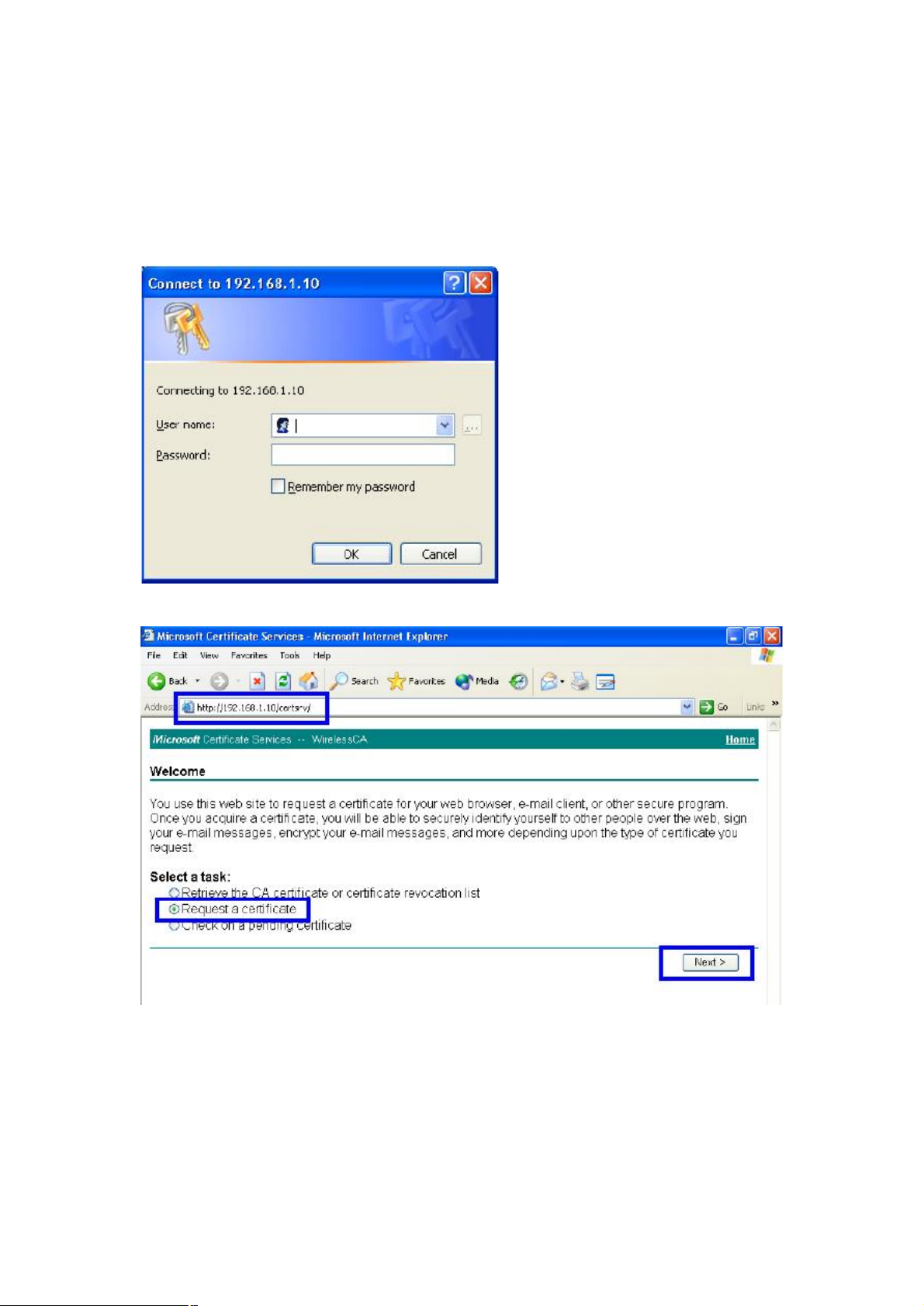
1. Active web browser, enter “http://192.168.1.10/certsrv” in the Address field which 192.168.1.10 is the
IP address of our server. This will directly access to Certificate Service of a Windows 2000 server. A
dialog box will prompt you to enter user name and password.
2. Enter a valid user name and password, then click “OK” to continue.
3. Select “Request a certificate”, and click “Next” to continue.
4. Select “User Certificate request”, and click “Next” to continue.
- 51 -

5. Click “Submit >” to continue.
6. The Certificate Service is now processing the certificate request.
- 52 -

7. The certificate is issued by the server, click “Install this certificate” to download and store the
certificate to your local computer.
8. Click “Yes” to store the certificate to your local computer.
9. Certificate is now installed.
Wireless Adapter Setup
1. Go to Start > Control Panel, double-click on “Network Connections”.
- 53 -

2. Right-click on the Wireless Network Connection which using WL-3555.
3. Click “Properties” to open up the Properties setting window.
4. Click on the “Wireless Network” tab.
5. Click “Properties” of one available wireless network, which you want to associate with.
- 54 -

6. Select “The key is provided for me automatically” option.
7. Click “OK”.
- 55 -

8. Click “Authentication” tab
9. Select “Enable network access control using IEEE 802.1X” option to enable 802.1x authentication.
10. Select “Smart Card or other Certificate” from the drop-down list box for EAP type.
11. Click “OK”.
12. When wireless client has associated with WRT-410, Windows XP will prompt you to select a
certificate for wireless network connection. If you only have one certificate in local computer, system will
automatically use it for authenticate. If you have multiple certificates in local computer, click on the
network connection icon in the system tray to continue.
- 56 -

13. Select the certificate that was issued by the server (in our demonstration: WirelessCA), and click
“OK” to continue.
14. Make sure this certificate is issued by correct server, and click “OK” to complete the authentication
process.
- 57 -

Chapter 5 Troubleshooting
This chapter provides solutions to problems usually encountered during the installation and operation of
the Wireless Broadband Router. Read the description below to solve your problems.
5.1 Frequently Asked Questions
What is WPA (Wi-Fi Protected Access)?
WPA resolves the issue of weak WEP headers, which are called initialization vectors (IV), and
provides a way of insuring the integrity of the messages passed through MIC (called Michael or
message integrity check) using TKIP (the Temporal Key Integrity Protocol) to enhance data
encryption. WPA-PSK is a special mode of WPA for home users without an enterprise
authentication server and provides the same strong encryption protection. WPA is not an official
IEEE standard, but is based on and is expected to be compatible with the upcoming 802.11i
security standard
Can I run an application from a remote computer over the wireless network?
This will depend on whether or not the application is designed to be used over a network. Consult
the application’s user guide to determine if it supports operation over a network.
Can I play games with other members of the wireless network?
Yes, as long as the game supports multiple plays over a LAN (local area network). Refer to the
game’s user guide for more information.
What is the IEEE 802.11b standard?
The IEEE 802.11b Wireless LAN standards subcommittee, which is formulating a standard for the
industry. The objective is to enable wireless LAN hardware from different manufactures to
communicate.
What IEEE 802.11 features are supported?
The product supports the following IEEE 802.11 functions:
• CSMA/CA plus Acknowledge protocol
• Multi-Channel Roaming
• Automatic Rate Selection
• RTS/CTS feature
• Fragmentation
• Power Management
What is PBCC?
- 58 -

This new products use the ACX100 chip from Texas Instruments. In addition to meeting the existing
standard, the chip also supports a new modulation scheme developed by TI, called Packet Binary
Convolution Code (PBCC). It's this scheme that gives the products the extra kick: Even at lower
speeds, PBCC provides better performance at greater distances, and it can also work at 22 Mbps.
What is Ad-hoc?
An Ad-hoc integrated wireless LAN is a group of computers, each with a WLAN adapter, connected
as an independent wireless LAN. Ad hoc wireless LAN is applicable at a departmental scale for a
branch or SOHO operation.
What is Infrastructure?
An integrated wireless and wired LAN is called an Infrastructure configuration. Infrastructure is
applicable to enterprise scale for wireless access to central database, or wireless application for
mobile workers.
What is Roaming?
Roaming is the ability of a portable computer user to communicate continuously while moving
freely throughout an area greater than that covered by a single Wireless Network Access Point.
Before using the roaming function, the workstation must make sure that it is the same channel
number with the Wireless Network Access Point of dedicated coverage area.
5.2 Glossary
ACCESS POINT
Access points are way stations in a wireless LAN that are connected to an Ethernet hub or server. Users
can roam within the range of access points and their wireless device connections are passed from one
access point to the next.
AUTHENTICATION
Authentication refers to the verification of a transmitted message's integrity.
DMZ
DMZ (DeMilitarized Zone) is a part of an network that is located between a secure LAN and an insecure
WAN. DMZs provide a way for some clients to have unrestricted access to the Internet.
BEACON INTERVAL
Refers to the interval between packets sent sent by access points for the purposes of synchronizing
wireless LANs.
DHCP
DHCP (Dynamic Host Configuration Protocol) software automatically assigns IP addresses to client
stations logging onto a TCP/IP network, which eliminates the need to manually assign permanent IP
addresses.
- 59 -

DNS
DNS stands for Domain Name System. DNS converts machine names to the IP addresses that all
machines on the net have. It translates from name to address and from address to name.
DOMAIN NAME
The domain name typically refers to an Internet site address.
DTIM
DTIM (Delivery Traffic Indication Message) provides client stations with information on the next
opportunity to monitor for broadcast or multicast messages.
FILTER
Filters are schemes which only allow specified data to be transmitted. For example, the router can filter
specific IP addresses so that users cannot connect to those addresses.
FIREWALL
Firewalls are methods used to keep networks secure from malicious intruders and unauthorized access.
Firewalls use filters to prevent unwanted packets from being transmitted. Firewalls are typically used to
provide secure access to the Internet while keeping an organization's public Web server separate from
the internal LAN.
FIRMWARE
Firmware refers to memory chips that retain their content without electrical power (for example, BIOS
ROM). The router firmware stores settings made in the interface.
FRAGMENTATION
Refers to the breaking up of data packets during transmission.
FTP
FTP (File Transfer Protocol) is used to transfer files over a TCP/IP network, and is typically used for
transferring large files or uploading the HTML pages for a Web site to the Web server.
GATEWAY
Gateways are computers that convert protocols enabling different networks, applications, and operating
systems to exchange information.
HOST NAME
The name given to a computer or client station that acts as a source for information on the network.
HTTP
HTTP (HyperText Transport Protocol) is the communications protocol used to connect to servers on the
World Wide Web. HTTP establishes a connection with a Web server and transmits HTML pages to client
browser (for example Windows IE). HTTP addresses all begin with the prefix 'http://' prefix (for example,
http://www.yahoo.com).
ICMP
ICMP (Internet Control Message Protocol) is a TCP/IP protocol used to send error and control messages
over the LAN (for example, it is used by the router to notify a message sender that the destination node is
not available).
- 60 -

IP
IP (Internet Protocol) is the protocol in the TCP/IP communications protocol suite that contains a network
address and allows messages to be routed to a different network or subnet. However, IP does not ensure
delivery of a complete message—TCP provides the function of ensuring delivery.
IP ADDRESS
The IP (Internet Protocol) address refers to the address of a computer attached to a TCP/IP network.
Every client and server station must have a unique IP address. Clients are assigned either a permanent
address or have one dynamically assigned to them via DHCP. IP addresses are written as four sets of
numbers separated by periods (for example, 211.23.181.189).
ISP
An ISP is an organization providing Internet access service via modems, ISDN (Integrated Services
Digital Network), and private lines.
LAN
LANs (Local Area Networks) are networks that serve users within specific geographical areas, such as in
a company building. LANs are comprised of servers, workstations, a network operating system, and
communications links such as the router.
MAC ADDRESS
A MAC address is a unique serial number burned into hardware adapters, giving the adapter a unique
identification.
METRIC
A number that indicates how long a packet takes to get to its destination.
MTU
MTU (Maximum Transmission/Transfer Unit) is the largest packet size that can be sent over a network.
Messages larger than the MTU are divided into smaller packets.
NAT
NAT (Network Address Translation - also known as IP masquerading) enables an organization to present
itself to the Internet with one address. NAT converts the address of each LAN node into one IP address
for the Internet (and vice versa). NAT also provides a certain amount of security by acting as a firewall by
keeping individual IP addresses hidden from the WAN.
(NETWORK) ADMINISTRATOR
The network administrator is the person who manages the LAN within an organization. The
administrator's job includes ensuring network security, keeping software, hardware, and firmware
up-to-date, and keeping track of network activity.
NTP
NTP (Network Time Protocol) is used to synchronize the realtime clock in a computer. Internet primary
and secondary servers synchronize to Coordinated Universal Time (UTC).
PACKET
A packet is a portion of data that is transmitted in network communications. Packets are also sometimes
called frames and datagrams. Packets contain not only data, but also the destination IP address.
- 61 -

PING
Ping (Packet INternet Groper) is a utility used to find out if a particular IP address is present online, and is
usually used by networks for debugging.
PORT
Ports are the communications pathways in and out of computers and network devices (routers and
switches). Most PCs have serial and parallel ports, which are external sockets for connecting devices
such as printers, modems, and mice. All network adapters use ports to connect to the LAN. Ports are
typically numbered.
PPPOE
PPPoE (Point-to-Point Protocol Over Ethernet) is used for running PPP protocol (normally used for
dial-up Internet connections) over an Ethernet.
PREAMBLE
Preamble refers to the length of a CRC (Cyclic Redundancy Check) block that monitors communications
between roaming wireless enabled devices and access points.
PROTOCOL
A protocol is a rule that governs the communication of data.
RIP
RIP (Routing Information Protocol) is a routing protocol that is integrated in the TCP/IP protocol. RIP finds
a route that is based on the smallest number of hops between the source of a packet and its destination.
RTS
RTS (Request To Send) is a signal sent from the transmitting station to the receiving station requesting
permission to transmit data.
SERVER
Servers are typically powerful and fast machines that store programs and data. The programs and data
are shared by client machines (workstations) on the network.
SMTP
SMTP (Simple Mail Transfer Protocol) is the standard Internet e-mail protocol. SMTP is a TCP/IP
protocol defining message format and includes a message transfer agent that stores and forwards mail.
SNMP
SNMP (Simple Network Management Protocol) is a widely used network monitoring and control protocol.
SNMP hardware or software components transmit network device activity data to the workstation used to
oversee the network.
SSID
SSID (Service Set Identifier) is a security measure used in WLANs. The SSID is a unique identifier
attached to packets sent over WLANs. This identifier emulates a password when a wireless device
attempts communication on the WLAN. Because an SSID distinguishes WLANS from each other, access
points and wireless devices trying to connect to a WLAN must use the same SSID.
SUBNET MASK
Subnet Masks (SUBNETwork masks) are used by IP protocol to direct messages into a specified network
segment (i.e., subnet). A subnet mask is stored in the client machine, server or router and is compared
- 62 -

with an incoming IP address to determine whether to accept or reject the packet.
SYSLOG SERVER
A SysLog server monitors incoming Syslog messages and decodes the messages for logging purposes.
TCP
(Transmission Control Protocol) is the transport protocol in TCP/IP that ensures messages over the
network are transmitted accurately and completely.
TCP/IP
TCP/IP (Transmission Control Protocol/Internet Protocol) is the main Internet communications protocol.
The TCP part ensures that data is completely sent and received at the other end. Another part of the
TCP/IP protocol set is UDP, which is used to send data when accuracy and guaranteed packet delivery
are not as important (for example, in realtime video and audio transmission).
The IP component of TCP/IP provides data routability, meaning that data packets contain the destination
station and network addresses, enabling TCP/IP messages to be sent to multiple networks within the
LAN or in the WAN.
TELNET
Telnet is a terminal emulation protocol commonly used on the Internet and TCP- or IP-based networks.
Telnet is used for connecting to remote devices and running programs. Telnet is an integral component of
the TCP/IP communications protocol.
UDP
(User Datagram Protocol) is a protocol within TCP/IP that is used to transport information when accurate
delivery isn't necessary (for example, realtime video and audio where packets can be dumped as there is
no time for retransmitting the data).
VIRTUAL SERVERS
Virtual servers are client servers (such as Web servers) that share resources with other virtual servers
(i.e., it is not a dedicated server).
WEP
WEP (Wired Equivalent Privacy) is the de facto security protocol for wireless LANs, providing the
"equivalent" security available in hardwired networks.
WIRELESS LAN
Wireless LANs (WLANs) are local area networks that use wireless communications for transmitting data.
Transmissions are usually in the 2.4 GHz band. WLAN devices do not need to be lined up for
communications like infrared devices. WLAN devices use access points which are connected to the
wired LAN and provide connectivity to the LAN. The radio frequency of WLAN devices is strong enough
to be transmitted through non-metal walls and objects, and can cover an area up to a thousand feet.
Laptops and notebooks use wireless LAN PCMCIA cards while PCs use plug-in cards to access the
WLAN.
WLAN
WLANs (Wireless LANs) are local area networks that use wireless communications for transmitting data.
Transmissions are usually in the 2.4 GHz band. WLAN devices do not need to be lined up for
communications like infrared devices. WLAN devices use access points which are connected to the
wired LAN and provide connectivity to the LAN. The radio frequency of WLAN devices is strong enough
to be transmitted through non-metal walls and objects, and can cover an area up to a thousand feet.
Laptops and notebooks use wireless LAN PCMCIA cards while PCs use plug-in cards to access the
- 63 -

WLAN.
WAN
WAN (Wide Area Network) is a communications network that covers a wide geographic area such as a
country (contrasted with a LAN, which covers a small area such as a company building).
- 64 -
 Loading...