

IBM x3400 7975, x3400 7976, x3400 7973, x3400 7974 Problem Determination And Service Manual
Page 1

System x3400
Ty pes 7973, 7974, 7975, and 7976
Problem Dete rminatio n and Service Guid e
Page 2

Page 3

System x3400
Ty pes 7973, 7974, 7975, and 7976
Problem Dete rminatio n and Service Guid e
Page 4

Note: Before using this information and the product it supports, read the general information in “Notices,” on page 175, and the
Warranty and Support Information document on the IBM xSeries Documentation CD.
Third Edition (Ocotober 2006)
© Copyright International Business Machines Corporation 2006. All rights reserved.
US Government Users Restricted Rights – Use, duplication or disclosure restricted by GSA ADP Schedule Contract
with IBM Corp.
Page 5

Contents
Safety . . . . . . . . . . . . . . . . . . . . . . . . . . . . vii
Guidelines for trained service technicians . . . . . . . . . . . . . . . viii
Inspecting for unsafe conditions . . . . . . . . . . . . . . . . . viii
Guidelines for servicing electrical equipment . . . . . . . . . . . . .ix
Safety statements . . . . . . . . . . . . . . . . . . . . . . . .x
Chapter 1. Introduction . . . . . . . . . . . . . . . . . . . . . .1
Related documentation . . . . . . . . . . . . . . . . . . . . . .1
Notices and statements in this document . . . . . . . . . . . . . . . .2
Machine Types 7973 and 7974 features and specifications . . . . . . . . .3
Machine Types 7975 and 7976 features and specifications . . . . . . . . .4
Server controls, LEDs, and connectors . . . . . . . . . . . . . . . .6
Front view . . . . . . . . . . . . . . . . . . . . . . . . . .6
Rear view . . . . . . . . . . . . . . . . . . . . . . . . . .9
Internal connectors, LEDs, and switches . . . . . . . . . . . . . . .11
System-board internal connectors . . . . . . . . . . . . . . . . .11
System-board external connectors . . . . . . . . . . . . . . . . .12
System-board option connectors . . . . . . . . . . . . . . . . .13
System-board LEDs . . . . . . . . . . . . . . . . . . . . . .14
System-board switches . . . . . . . . . . . . . . . . . . . . .15
Chapter 2. Diagnostics . . . . . . . . . . . . . . . . . . . . .17
Diagnostic tools . . . . . . . . . . . . . . . . . . . . . . . .17
POST . . . . . . . . . . . . . . . . . . . . . . . . . . . .17
POST beep codes . . . . . . . . . . . . . . . . . . . . . .18
No-beep symptoms . . . . . . . . . . . . . . . . . . . . . .21
Error logs . . . . . . . . . . . . . . . . . . . . . . . . . .22
Viewing error logs from the Configuration/Setup Utility program . . . . . .23
Viewing the BMC log from the diagnostic programs . . . . . . . . . .23
POST error codes . . . . . . . . . . . . . . . . . . . . . . .24
Checkout procedure . . . . . . . . . . . . . . . . . . . . . . .39
About the checkout procedure . . . . . . . . . . . . . . . . . .39
Performing the checkout procedure . . . . . . . . . . . . . . . .40
Checkpoint codes (trained service technicians only) . . . . . . . . . . .40
Troubleshooting tables . . . . . . . . . . . . . . . . . . . . . .41
CD or DVD drive problems . . . . . . . . . . . . . . . . . . .41
Diskette drive problems . . . . . . . . . . . . . . . . . . . . .42
General problems . . . . . . . . . . . . . . . . . . . . . . .43
Hard disk drive problems . . . . . . . . . . . . . . . . . . . .43
Intermittent problems . . . . . . . . . . . . . . . . . . . . . .44
Keyboard, mouse, or pointing-device problems . . . . . . . . . . . .44
Memory problems . . . . . . . . . . . . . . . . . . . . . . .46
Microprocessor problems . . . . . . . . . . . . . . . . . . . .47
Monitor or video problems . . . . . . . . . . . . . . . . . . . .47
Optional-device problems . . . . . . . . . . . . . . . . . . . .50
Power problems . . . . . . . . . . . . . . . . . . . . . . .51
Serial port problems . . . . . . . . . . . . . . . . . . . . . .52
ServerGuide problems . . . . . . . . . . . . . . . . . . . . .53
Software problems . . . . . . . . . . . . . . . . . . . . . .53
Universal Serial Bus (USB) port problems . . . . . . . . . . . . . .54
Error LEDs . . . . . . . . . . . . . . . . . . . . . . . . . .55
Power-supply LEDs . . . . . . . . . . . . . . . . . . . . . . .56
Diagnostic programs, messages, and error codes . . . . . . . . . . . .58
© Copyright IBM Corp. 2006 iii
Page 6

Running the diagnostic programs . . . . . . . . . . . . . . . . .58
Diagnostic text messages . . . . . . . . . . . . . . . . . . . .59
Viewing the test log . . . . . . . . . . . . . . . . . . . . . .59
Diagnostic error codes . . . . . . . . . . . . . . . . . . . . .60
Recovering from a BIOS update failure . . . . . . . . . . . . . . . .72
System-error log messages . . . . . . . . . . . . . . . . . . . .74
Solving SCSI problems . . . . . . . . . . . . . . . . . . . . . .82
Solving power problems . . . . . . . . . . . . . . . . . . . . .82
Solving Ethernet controller problems . . . . . . . . . . . . . . . . .83
Solving undetermined problems . . . . . . . . . . . . . . . . . . .84
Calling IBM for service . . . . . . . . . . . . . . . . . . . . . .85
Chapter 3. Parts listing, System x3400 Types 7973, 7974, 7975 and 7976 87
Replaceable server components . . . . . . . . . . . . . . . . . .88
Power cords . . . . . . . . . . . . . . . . . . . . . . . . . .92
Chapter 4. Removing and replacing server components . . . . . . . .95
Installation guidelines . . . . . . . . . . . . . . . . . . . . . .95
System reliability guidelines . . . . . . . . . . . . . . . . . . .96
Working inside the server with the power on . . . . . . . . . . . . .96
Handling static-sensitive devices . . . . . . . . . . . . . . . . .97
Returning a device or component . . . . . . . . . . . . . . . . .97
Removing and replacing Tier 1 CRUs . . . . . . . . . . . . . . . .98
Removing the bezel . . . . . . . . . . . . . . . . . . . . . .98
Replacing the bezel . . . . . . . . . . . . . . . . . . . . . .99
Removing the side cover . . . . . . . . . . . . . . . . . . . . 100
Installing the side cover . . . . . . . . . . . . . . . . . . . . 101
Removing an adapter . . . . . . . . . . . . . . . . . . . . . 102
Installing an adapter . . . . . . . . . . . . . . . . . . . . . 103
Removing and installing internal drives . . . . . . . . . . . . . . 105
Removing a hot-swap power supply . . . . . . . . . . . . . . . .116
Installing a hot-swap power supply . . . . . . . . . . . . . . . .118
Removing a memory module . . . . . . . . . . . . . . . . . .119
Installing a memory module . . . . . . . . . . . . . . . . . . . 120
Removing a hot-swap fan . . . . . . . . . . . . . . . . . . . 122
Installing a hot-swap fan . . . . . . . . . . . . . . . . . . . . 123
Removing the rear system fan cage assembly with baffle . . . . . . . . 124
Installing the rear system fan cage assembly with baffle . . . . . . . . 124
Removing the front system fan cage assembly . . . . . . . . . . . . 126
Installing the front system fan cage assembly . . . . . . . . . . . . 128
Removing the front USB connector assembly . . . . . . . . . . . . . 129
Installing the front USB connector assembly . . . . . . . . . . . . . . 130
Removing the rear adapter retention bracket . . . . . . . . . . . . . 130
Installing the rear adapter retention bracket . . . . . . . . . . . . . . 131
Removing the front adapter-retention bracket . . . . . . . . . . . . . 132
Installing the front adapter-retention bracket . . . . . . . . . . . . . . 132
Removing and replacing Tier 2 CRUs . . . . . . . . . . . . . . . . 133
Removing the battery . . . . . . . . . . . . . . . . . . . . . 133
Installing the battery . . . . . . . . . . . . . . . . . . . . . 133
Removing the ServeRAID 8k-l adapter . . . . . . . . . . . . . . . 134
Installing the ServeRAID 8k-l adapter . . . . . . . . . . . . . . . 135
Removing the ServeRAID-8k adapter . . . . . . . . . . . . . . . 135
Installing the ServeRAID-8k adapter . . . . . . . . . . . . . . . 136
DIMM air duct . . . . . . . . . . . . . . . . . . . . . . . . 138
Installing the DIMM air duct . . . . . . . . . . . . . . . . . . . 139
Removing the control-panel assembly . . . . . . . . . . . . . . . 140
iv System x3400 Types 7973, 7974, 7975, and 7976: Problem Determination and Service Guide
Page 7

Installing the control-panel assembly . . . . . . . . . . . . . . . 142
Removing and replacing FRUs . . . . . . . . . . . . . . . . . . 143
Removing the hot-swap power-supply cage assembly . . . . . . . . . 143
Installing the hot-swap power-supply cage assembly . . . . . . . . . 145
Removing the simple-swap backplate . . . . . . . . . . . . . . . 146
Installing the simple-swap backplate . . . . . . . . . . . . . . . 148
Removing the SAS/SATA backplane . . . . . . . . . . . . . . . 149
Installing the SAS/SATA backplane . . . . . . . . . . . . . . . . 150
Removing a non-hot-swap power supply cage assembly . . . . . . . . 150
Installing a non-hot-swap power supply cage assembly . . . . . . . . 153
Removing the hot-swap power supply docking cable assembly . . . . . . 153
Installing the hot-swap power supply docking cable assembly . . . . . . 154
Removing the microprocessor and heat sink . . . . . . . . . . . . 155
Installing a microprocessor and heat sink . . . . . . . . . . . . . . 157
Removing the system board . . . . . . . . . . . . . . . . . . 161
Installing the system board . . . . . . . . . . . . . . . . . . . 163
Chapter 5. Configuration information and instructions . . . . . . . . 165
Updating the firmware . . . . . . . . . . . . . . . . . . . . . . 165
Configuring the server . . . . . . . . . . . . . . . . . . . . . . 165
Using the ServerGuide Setup and Installation CD . . . . . . . . . . . 166
Using the Configuration/Setup Utility program . . . . . . . . . . . . 166
Using the RAID configuration programs . . . . . . . . . . . . . . 166
Using ServeRAID Manager . . . . . . . . . . . . . . . . . . . 171
Using the Boot Menu program . . . . . . . . . . . . . . . . . . 172
Configuring the Ethernet controller . . . . . . . . . . . . . . . . 173
Appendix. Notices . . . . . . . . . . . . . . . . . . . . . . . 175
Trademarks . . . . . . . . . . . . . . . . . . . . . . . . . . 175
Important notes . . . . . . . . . . . . . . . . . . . . . . . . 177
Product recycling and disposal . . . . . . . . . . . . . . . . . . 177
Battery return program . . . . . . . . . . . . . . . . . . . . . 179
Electronic emission notices (Class A) . . . . . . . . . . . . . . . . 180
Federal Communications Commission (FCC) statement . . . . . . . . 180
Industry Canada Class A emission compliance statement . . . . . . . . 180
Australia and New Zealand Class A statement . . . . . . . . . . . . 180
United Kingdom telecommunications safety requirement . . . . . . . . 180
European Union EMC Directive conformance statement . . . . . . . . 181
Taiwanese Class A warning statement . . . . . . . . . . . . . . . 181
Chinese Class A warning statement . . . . . . . . . . . . . . . . 181
Japanese Voluntary Control Council for Interference (VCCI) statement 181
Getting help and technical assistance . . . . . . . . . . . . . . . 183
Before you call . . . . . . . . . . . . . . . . . . . . . . . . 183
Using the documentation . . . . . . . . . . . . . . . . . . . . . 183
Getting help and information from the World Wide Web . . . . . . . . . 183
Software service and support . . . . . . . . . . . . . . . . . . . 184
Hardware service and support . . . . . . . . . . . . . . . . . . . 184
Index . . . . . . . . . . . . . . . . . . . . . . . . . . . . 185
Contents v
Page 8

vi System x3400 Types 7973, 7974, 7975, and 7976: Problem Determination and Service Guide
Page 9
Safety
Before installing this product, read the Safety Information.
Antes de instalar este produto, leia as Informações de Segurança.
Pred instalací tohoto produktu si prectete prírucku bezpecnostních instrukcí.
Læs sikkerhedsforskrifterne, før du installerer dette produkt.
Lees voordat u dit product installeert eerst de veiligheidsvoorschriften.
Ennen kuin asennat tämän tuotteen, lue turvaohjeet kohdasta Safety Information.
Avant d’installer ce produit, lisez les consignes de sécurité.
Vor der Installation dieses Produkts die Sicherheitshinweise lesen.
Prima di installare questo prodotto, leggere le Informazioni sulla Sicurezza.
Les sikkerhetsinformasjonen (Safety Information) før du installerer dette produktet.
Antes de instalar este produto, leia as Informações sobre Segurança.
Antes de instalar este producto, lea la información de seguridad.
Läs säkerhetsinformationen innan du installerar den här produkten.
© Copyright IBM Corp. 2006 vii
Page 10

Guidelines for trained service technicians
This section contains information for trained service technicians.
Inspecting for unsafe conditions
Use the information in this section to help you identify potential unsafe conditions in
an IBM® product that you are working on. Each IBM product, as it was designed
and manufactured, has required safety items to protect users and service
technicians from injury. The information in this section addresses only those items.
Use good judgment to identify potential unsafe conditions that might be caused by
non-IBM alterations or attachment of non-IBM features or options that are not
addressed in this section. If you identify an unsafe condition, you must determine
how serious the hazard is and whether you must correct the problem before you
work on the product.
Consider the following conditions and the safety hazards that they present:
v Electrical hazards, especially primary power. Primary voltage on the frame can
cause serious or fatal electrical shock.
v Explosive hazards, such as a damaged CRT face or a bulging or leaking
capacitor.
v Mechanical hazards, such as loose or missing hardware.
inspect the product for potential unsafe conditions, complete the following steps:
To
1. Make sure that the power is off and the power cord is disconnected.
2. Make sure that the exterior cover is not damaged, loose, or broken, and
observe any sharp edges.
3. Check the power cord:
v Make sure that the third-wire ground connector is in good condition. Use a
meter to measure third-wire ground continuity for 0.1 ohm or less between
the external ground pin and the frame ground.
v Make sure that the power cord is the correct type, as specified in “Power
cords” on page 92.
v Make sure that the insulation is not frayed or worn.
Remove the cover.
4.
5. Check for any obvious non-IBM alterations. Use good judgment as to the safety
of any non-IBM alterations.
6. Check inside the server for any obvious unsafe conditions, such as metal filings,
contamination, water or other liquid, or signs of fire or smoke damage.
7. Check for worn, frayed, or pinched cables.
8. Make sure that the power-supply cover fasteners (screws or rivets) have not
been removed or tampered with.
viii System x3400 Types 7973, 7974, 7975, and 7976: Problem Determination and Service Guide
Page 11

Guidelines for servicing electrical equipment
Observe the following guidelines when servicing electrical equipment:
v Check the area for electrical hazards such as moist floors, nongrounded power
extension cords, power surges, and missing safety grounds.
v Use only approved tools and test equipment. Some hand tools have handles that
are covered with a soft material that does not provide insulation from live
electrical currents.
v Regularly inspect and maintain your electrical hand tools for safe operational
condition. Do not use worn or broken tools or testers.
v Do not touch the reflective surface of a dental mirror to a live electrical circuit.
The surface is conductive and can cause personal injury or equipment damage if
it touches a live electrical circuit.
v Some rubber floor mats contain small conductive fibers to decrease electrostatic
discharge. Do not use this type of mat to protect yourself from electrical shock.
v Do not work alone under hazardous conditions or near equipment that has
hazardous voltages.
v Locate the emergency power-off (EPO) switch, disconnecting switch, or electrical
outlet so that you can turn off the power quickly in the event of an electrical
accident.
v Disconnect all power before you perform a mechanical inspection, work near
power supplies, or remove or install main units.
v Before you work on the equipment, disconnect the power cord. If you cannot
disconnect the power cord, have the customer power-off the wall box that
supplies power to the equipment and lock the wall box in the off position.
v Never assume that power has been disconnected from a circuit. Check it to
make sure that it has been disconnected.
v If you have to work on equipment that has exposed electrical circuits, observe
the following precautions:
– Make sure that another person who is familiar with the power-off controls is
near you and is available to turn off the power if necessary.
– When you are working with powered-on electrical equipment, use only one
hand. Keep the other hand in your pocket or behind your back to avoid
creating a complete circuit that could cause an electrical shock.
– When using a tester, set the controls correctly and use the approved probe
leads and accessories for that tester.
– Stand on a suitable rubber mat to insulate you from grounds such as metal
floor strips and equipment frames.
Use extreme care when measuring high voltages.
v
v To ensure proper grounding of components such as power supplies, pumps,
blowers, fans, and motor generators, do not service these components outside of
their normal operating locations.
v If an electrical accident occurs, use caution, turn off the power, and send another
person to get medical aid.
Safety ix
Page 12

Safety statements
Important:
Each caution and danger statement in this documentation begins with a number.
This number is used to cross reference an English-language caution or danger
statement with translated versions of the caution or danger statement in the Safety
Information document.
For example, if a caution statement begins with a number 1, translations for that
caution statement appear in the Safety Information document under statement 1.
Be sure to read all caution and danger statements in this documentation before
performing the instructions. Read any additional safety information that comes with
your server or optional device before you install the device.
x System x3400 Types 7973, 7974, 7975, and 7976: Problem Determination and Service Guide
Page 13
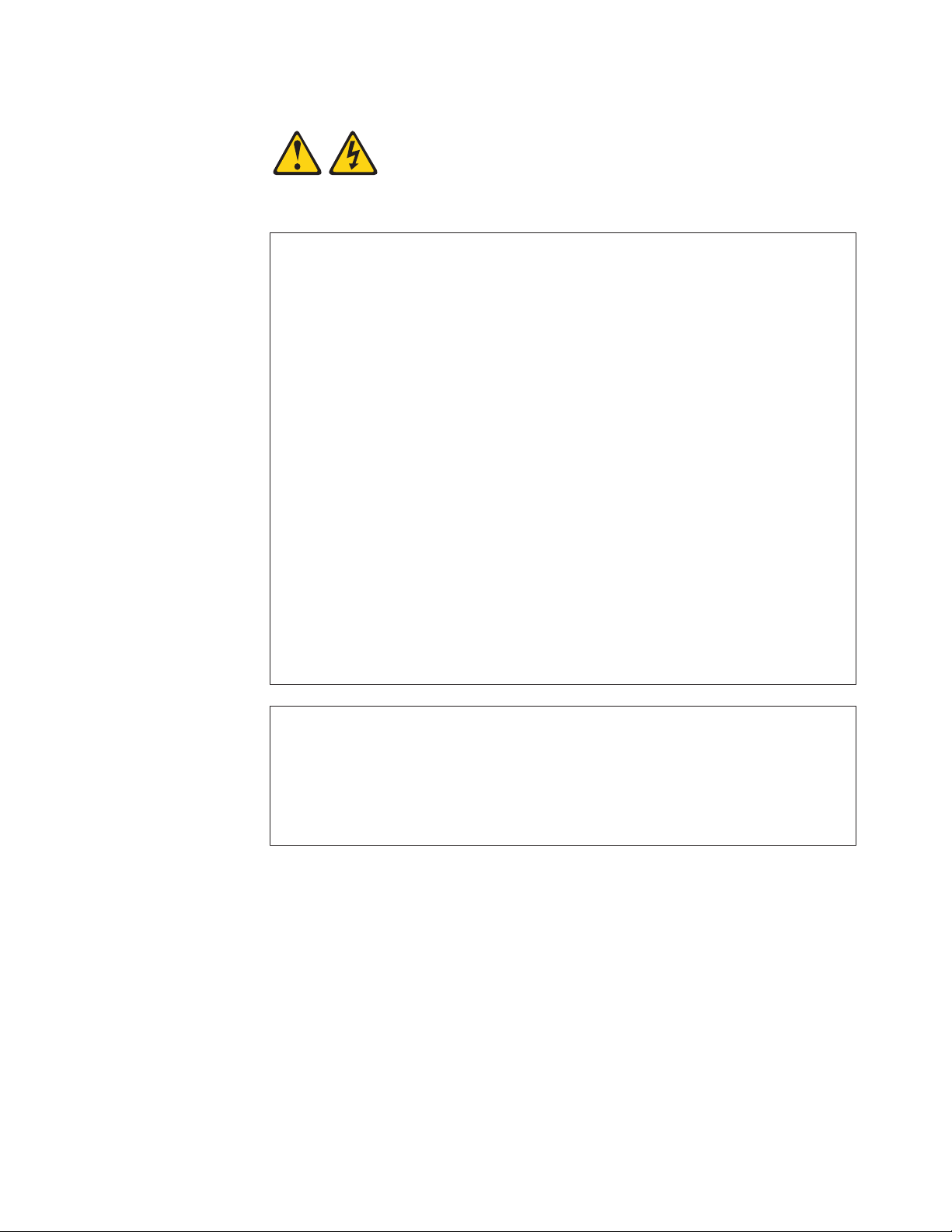
Statement 1:
DANGER
Electrical
current from power, telephone, and communication cables is
hazardous.
To avoid a shock hazard:
v Do not connect or disconnect any cables or perform installation,
maintenance, or reconfiguration of this product during an electrical
storm.
v Connect all power cords to a properly wired and grounded electrical
outlet.
v Connect to properly wired outlets any equipment that will be attached to
this product.
v When possible, use one hand only to connect or disconnect signal
cables.
v Never turn on any equipment when there is evidence of fire, water, or
structural damage.
v Disconnect the attached power cords, telecommunications systems,
networks, and modems before you open the device covers, unless
instructed otherwise in the installation and configuration procedures.
v Connect and disconnect cables as described in the following table when
installing, moving, or opening covers on this product or attached
devices.
To Connect: To Disconnect:
1. Turn everything OFF.
2. First, attach all cables to devices.
3. Attach signal cables to connectors.
4. Attach power cords to outlet.
1. Turn everything OFF.
2. First, remove power cords from outlet.
3. Remove signal cables from connectors.
4. Remove all cables from devices.
5. Turn device ON.
Safety xi
Page 14
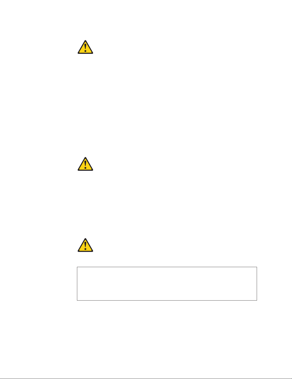
Statement 2:
CAUTION:
When replacing the lithium battery, use only IBM Part Number 33F8354 or an
equivalent type battery recommended by the manufacturer. If your system has
a module containing a lithium battery, replace it only with the same module
type made by the same manufacturer. The battery contains lithium and can
explode if not properly used, handled, or disposed of.
Do not:
v Throw or immerse into water
v Heat to more than 100°C (212°F)
v Repair or disassemble
Dispose
Statement 3:
of the battery as required by local ordinances or regulations.
CAUTION:
When laser products (such as CD-ROMs, DVD drives, fiber optic devices, or
transmitters) are installed, note the following:
v Do not remove the covers. Removing the covers of the laser product could
result in exposure to hazardous laser radiation. There are no serviceable
parts inside the device.
v Use of controls or adjustments or performance of procedures other than
those specified herein might result in hazardous radiation exposure.
DANGER
laser products contain an embedded Class 3A or Class 3B laser
Some
diode. Note the following.
Laser radiation when open. Do not stare into the beam, do not view directly
with optical instruments, and avoid direct exposure to the beam.
xii System x3400 Types 7973, 7974, 7975, and 7976: Problem Determination and Service Guide
Page 15
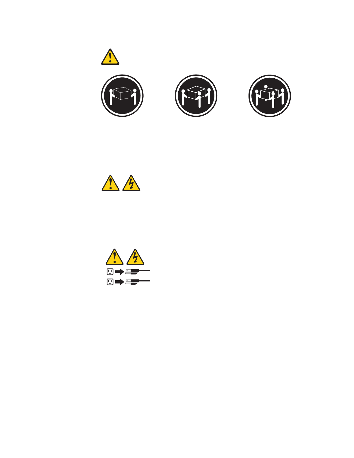
Statement 4:
≥ 18 kg (39.7 lb) ≥ 32 kg (70.5 lb) ≥ 55 kg (121.2 lb)
CAUTION:
Use safe practices when lifting.
Statement 5:
CAUTION:
The power control button on the device and the power switch on the power
supply do not turn off the electrical current supplied to the device. The device
also might have more than one power cord. To remove all electrical current
from the device, ensure that all power cords are disconnected from the power
source.
2
1
Safety xiii
Page 16
Statement 8:
CAUTION:
Never remove the cover on a power supply or any part that has the following
label attached.
Hazardous voltage, current, and energy levels are present inside any
component that has this label attached. There are no serviceable parts inside
these components. If you suspect a problem with one of these parts, contact
a service technician.
Statement 10:
CAUTION:
Do not place any object weighing more than 82 kg (180 lb) on top of
rack-mounted devices.
>82 kg (180 lb)
xiv System x3400 Types 7973, 7974, 7975, and 7976: Problem Determination and Service Guide
Page 17
Statement 11:
CAUTION:
The following label indicates sharp edges, corners, or joints nearby.
Statement 17:
CAUTION:
The following label indicates moving parts nearby.
Safety xv
Page 18

xvi System x3400 Types 7973, 7974, 7975, and 7976: Problem Determination and Service Guide
Page 19

Chapter 1. Introduction
This Problem Determination and Service Guide contains information to help you
solve problems that might occur in the IBM System x3400 Types 7973, 7974, 7975,
and 7976. It describes the diagnostic tools that come with the server, error codes
and suggested actions, and instructions for replacing failing components.
Replaceable components are of three types:
v Tier 1 customer replaceable unit (CRU): Replacement of Tier 1 CRUs is your
responsibility. If IBM installs a Tier 1 CRU at your request, you will be charged for
the installation.
v Tier 2 customer replaceable unit: You may install a Tier 2 CRU yourself or
request IBM to install it, at no additional charge, under the type of warranty
service that is designated for the server.
v Field replaceable unit (FRU): FRUs must be installed only by trained service
technicians.
information about the terms of the warranty and getting service and assistance,
For
see the Warranty and Support Information document.
Related documentation
In addition to this document, the following documentation also comes with the
server:
v Installation Guide
This printed document contains instructions for setting up the server and basic
instructions for installing some options.
v User’s Guide
This document is in Portable Document Format (PDF) on the IBM System x3400
Documentation CD. It provides general information about the server, including
information about features, and how to configure the server. It also contains
detailed instructions for installing, removing, and connecting optional devices that
the server supports.
v Rack Installation Instructions
This printed document contains instructions for installing the server in a rack.
v Safety Information
This document is in PDF on the IBM System x3400 Documentation CD. It
contains translated caution and danger statements. Each caution and danger
statement that appears in the documentation has a number that you can use to
locate the corresponding statement in your language in the Safety Information
document.
v Warranty and Support Information
This document is in PDF on the IBM System x3400 Documentation CD. It
contains information about the terms of the warranty and getting service and
assistance.
Depending
on the server model, additional documentation might be included on the
IBM System x3400 Documentation CD.
© Copyright IBM Corp. 2006 1
Page 20

The xSeries Tools Center is an online information center that contains information
about tools for updating, managing, and deploying firmware, device drivers, and
operating systems. The xSeries Tools Center is at http://publib.boulder.ibm.com/
infocenter/toolsctr/v1r0/index.jsp.
The server might have features that are not described in the documentation that
you received with the server. The documentation might be updated occasionally to
include information about those features, or technical updates might be available to
provide additional information that is not included in the server documentation.
These updates are available from the IBM Web site. Complete the following steps
to check for updated documentation and technical updates.
Note: Changes are made periodically to the IBM Web site. The actual procedure
might vary slightly from what is described in this document.
1. Go to http://www.ibm.com/support/.
2. Under Search technical support, type 7973, 7974, 7975, or 7976 (depending
on your model), and click Search.
Notices and statements in this document
The caution and danger statements that appear in this document are also in the
multilingual Safety Information document, which is on the IBM System x3400
Documentation CD. Each statement is numbered for reference to the corresponding
statement in the Safety Information document.
The following notices and statements are used in this document:
v Note: These notices provide important tips, guidance, or advice.
v Important: These notices provide information or advice that might help you avoid
inconvenient or problem situations.
v Attention: These notices indicate potential damage to programs, devices, or
data. An attention notice is placed just before the instruction or situation in which
damage could occur.
v Caution: These statements indicate situations that can be potentially hazardous
to you. A caution statement is placed just before the description of a potentially
hazardous procedure step or situation.
v Danger: These statements indicate situations that can be potentially lethal or
extremely hazardous to you. A danger statement is placed just before the
description of a potentially lethal or extremely hazardous procedure step or
situation.
2 System x3400 Types 7973, 7974, 7975, and 7976: Problem Determination and Service Guide
Page 21

Machine Types 7973 and 7974 features and specifications
The following information is a summary of the features and specifications for
Machine Types 7973 and 7974. Depending on the server model, some features
might not be available, or some specifications might not apply. See the User’s
Guide for more detail information about the specifications and features and the
installation of the components.
Table 1. Features and specifications
Microprocessor:
v Supports up to two Intel® Xeon
®
dual-core processors
v 4 MB shared Level-2 cache
v 667, 1066, or 1333 MHz front-side
bus (FSB)
Use the Configuration/Setup
Note:
Utility program to determine the type
and speed of the microprocessors.
Memory:
v Minimum: 1 GB
v Maximum: 32 GB (16 GB in mirrored
mode)
v Types: PC2-5300, ECC fully-buffered
with double-data-rate 2 (DDR2)
v Connectors: eight dual inline memory
module (DIMM) connectors, two-way
interleaved
(depending on the model):
Drives
v Diskette (optional): External USB
diskette drive
v Hard disk drive: SATA
v One of the following IDE drives:
– CD-ROM
– CD-RW (optional)
– DVD-ROM (optional)
– DVD-ROM/CD-RW (optional)
bays (depending on the
Drive
model):
v Three half-high 5.25-in. bays (one
CD or DVD drive installed) or one
half-high CD or DVD drive and one
full-high tape drive
v Four 3.5-in. simple-swap bays
Expansion
slots (depending on the
model):
v Six expansion slots
– Three PCI Express x8 slots (two
x8 links and one x4 link)
– One PCI 32-bit/33 MHz slot
– Two PCI-X 64-bit/133 MHz slots
Fans:
Three speed-controlled hot-swap fans
Power supply:
670 watt (90-240 V ac)
Size:
v Height: 440 mm (17.3 in.)
v Depth: 747 mm (29.4 in.)
v Width: 218 mm (8.6 in.)
v Weight: 20 kg (42 lb) to 34 kg (75 lb)
depending upon configuration
Integrated
functions:
v Baseboard management controller
(BMC) or onboard service processor
v Broadcom 5721 10/100/1000 Ethernet
controller on the system board with
RJ-45 Ethernet port
v Six-port, Serial ATA controller
v Integrated RAID capability (SATA
HostRAID)
v Remote Supervisor Adapter II SlimLine
v Two serial ports
v One parallel port
v Four Universal Serial Bus (USB) v2.0
ports (two on front and two on rear)
v Keyboard port
v Mouse port
v ATA-100 single-channel IDE controller
(bus mastering)
v ATI ES1000 video controller
– Compatible with SVGA and VGA
– 16 MB SDRAM video memory
Diagnostic
LEDs:
v Fans
v Memory
v Power supply
Acoustical
noise emissions:
v Sound power, idling: 5.6 bel
v Sound power, operating: 6.0 bel
Environment:
v Air temperature:
– Server on: 10° to 35°C (50° to 95°F)
Altitude: 0 to 914 m (2998.0 ft)
– Server off: -40° to 60°C (-40° to 140°F)
Altitude: 0 to 2133 m (7000.0 ft)
Humidity (operating and storage): 8% to
v
80%
output:
Heat
Approximate heat output in British thermal
units (Btu) per hour:
v Minimum configuration: 693 Btu per hour
(203 watts)
v Maximum configuration: 1631 Btu per hour
(478 watts)
Electrical input:
v Sine-wave input (50 or 60 Hz) required
v Input voltage and frequency ranges
automatically selected
v Input voltage low range:
– Minimum: 100 V ac
– Maximum: 127 V ac
v Input voltage high range:
– Minimum: 200 V ac
– Maximum: 240 V ac
v Input kilovolt-amperes (kVA) approximately:
– Minimum: 0.21 kVA (all models)
– Maximum: 0.49 kVA
Notes:
1. Power consumption and heat output vary
depending on the number and type of
optional features installed and the
power-management optional features in
use.
2. These levels were measured in controlled
acoustical environments according to the
procedures specified by the American
National Standards Institute (ANSI) S12.10
and ISO 7779 and are reported in
accordance with ISO 9296. Actual
sound-pressure levels in a given location
might exceed the average values stated
because of room reflections and other
nearby noise sources. The declared
sound-power levels indicate an upper limit,
below which a large number of computers
will operate.
Chapter 1. Introduction 3
Page 22

Machine Types 7975 and 7976 features and specifications
The following information is a summary of the features and specifications for
Machine Types 7975 and 7976. Depending on the server model, some features
might not be available, or some specifications might not apply. See the User’s
Guide for more detail information about the specifications and features and the
installation of the components.
4 System x3400 Types 7973, 7974, 7975, and 7976: Problem Determination and Service Guide
Page 23
Table 2. Features and specifications
Microprocessor:
v Supports up to two Intel Xeon
dual-core processors or two Intel
quad-core processors
Important: Do not mix dual-core
processors and quad-core processors
in the same server.
v 4 MB shared Level-2 cache
v 667, 1066, or 1333 MHz front-side
bus (FSB)
Use the Configuration/Setup
Note:
Utility program to determine the type
and speed of the microprocessors.
Memory:
v Minimum: 1 GB
v Maximum: 32 GB (16 GB in mirrored
mode)
v Types: PC2-5300, ECC fully-buffered
with double-data-rate 2 (DDR2)
v Connectors: eight dual inline memory
module (DIMM) connectors, two-way
interleaved
(depending on the model):
Drives
v Diskette (optional): External USB
diskette drive
v Hard disk drive: SATA or SAS
v One of the following IDE drives:
– CD-ROM
– CD-RW (optional)
– DVD-ROM (optional)
– DVD-ROM/CD-RW (optional)
bays (depending on the
Drive
model):
v Three half-high 5.25-in. bays (one
CD or DVD drive installed) or one
half-high CD or DVD drive and one
full-high tape drive
v Eight 3.5-in. hot-swap hard disk drive
bays
Note: Yo u can install up to eight
hot-swap drives when you order the
4-drive backplane option kit.
Expansion
model):
v Six expansion slots
– Three PCI Express x8 slots (two
– One PCI 32-bit/33 MHz slot
– Two PCI-X 64-bit/133 MHz slots
slots (depending on the
x8 links and one x4 link)
Fans: Three speed-control hot-swap fans
(standard)
Note: Six fans are required to provide
redundancy in hot-swap models; therefore,
you must install an additional redundant
power and cooling option kit (the option kit
comes with a hot-swap power supply and
three hot-swap fans) to upgrade to
redundant mode.
Power supply:
One of the following power supplies:
v One nonredundant 670 watt (90-240 V
ac)
v One 835 watt (90-240 V ac).
Note: Two 835 watt power supplies
provide redundancy in hot-swap
models; therefore, you must install an
additional redundant power and cooling
option kit (the option kit comes with an
835 watt hot-swap power supply and
three hot-swap fans) to upgrade to
redundant mode.
Size:
v Height: 440 mm (17.3 in.)
v Depth: 747 mm (29.4 in.)
v Width: 218 mm (8.6 in.)
v Weight: 20 kg (42 lb) to 34 kg (75 lb)
depending upon configuration
Integrated
functions:
v Baseboard management controller
(BMC) or onboard service processor
v Broadcom 5721 10/100/1000 Ethernet
controller on the system board with
RJ-45 Ethernet port
v Dual-channel (four ports per channel)
onboard SAS/SATA controller with
integrated RAID
v Remote Supervisor Adapter II SlimLine
v Two serial ports
v One parallel port
v Four Universal Serial Bus (USB) v2.0
ports (two on front and two on rear)
v Keyboard port
v Mouse port
v ATA-100 single-channel IDE controller
(bus mastering)
v ATI ES1000 video controller
– Compatible with SVGA and VGA
– 16 MB SDRAM video memory
Acoustical
noise emissions (depending
on your model):
v Sound power, idling: 5.6 bel or 6.0 bel
v Sound power, operating: 6.0 bel or 6.1
bel
Diagnostic LEDs:
v Fans
v Memory
v Hard disk drives (redundant models)
v Power supply
Environment:
v Air temperature:
– Server on: 10° to 35°C (50° to 95°F)
Altitude: 0 to 914 m (2998.0 ft)
– Server off: -40° to 60°C (-40° to 140°F)
Altitude: 0 to 2133 m (7000.0 ft)
v Humidity (operating and storage): 8% to
80%
output:
Heat
Approximate heat output in British thermal
units (Btu) per hour:
v Minimum configuration: 781 Btu per hour
(229 watts)
v Maximum configuration: 1910 Btu per hour
(560 watts)
Electrical input:
v Sine-wave input (50 or 60 Hz) required
v Input voltage and frequency ranges
automatically selected
v Input voltage low range:
– Minimum: 100 V ac
– Maximum: 127 V ac
Input voltage high range:
v
– Minimum: 200 V ac
– Maximum: 240 V ac
v Input kilovolt-amperes (kVA) approximately:
– Minimum: 0.23 kVA (all models)
– Maximum: 0.57 kVA
Notes:
1. Power consumption and heat output vary
depending on the number and type of
optional features installed and the
power-management optional features in
use.
2. These levels were measured in controlled
acoustical environments according to the
procedures specified by the American
National Standards Institute (ANSI) S12.10
and ISO 7779 and are reported in
accordance with ISO 9296. Actual
sound-pressure levels in a given location
might exceed the average values stated
because of room reflections and other
nearby noise sources. The declared
sound-power levels indicate an upper limit,
below which a large number of computers
will operate.
Chapter 1. Introduction 5
Page 24
Server controls, LEDs, and connectors
This section describes the controls, light-emitting diodes (LEDs), and connectors on
the front and rear of the server.
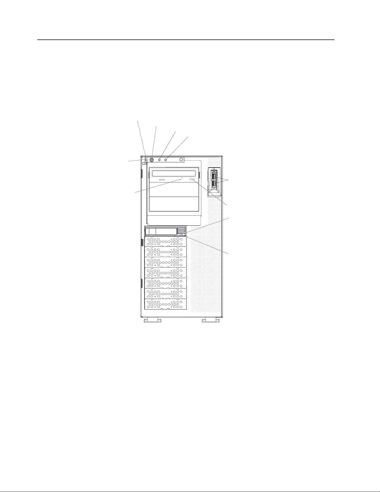
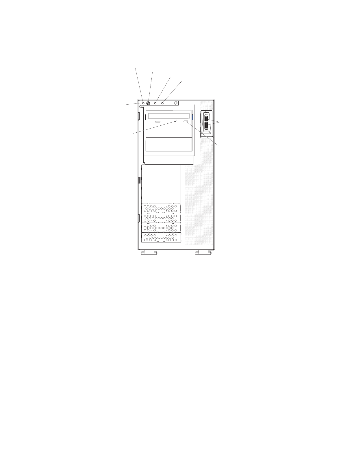
Front view
The following illustration shows the controls, LEDs, and connectors on the front of
the hot-swap server models.
Front
information
panel
CD or DVD drive
activity LED
(green)
System power LED
Power-control button
Hard disk drive activity LED
System error LED
USB connectors
CD or DVD-eject button
Hot-swap hard disk
drive status
LED (amber)
Hot-swap hard disk
drive activity
LED (green)
6 System x3400 Types 7973, 7974, 7975, and 7976: Problem Determination and Service Guide
Page 25
The following illustration shows the controls, LEDs, and connectors on the front of
the simple-swap server models.
Front
information
panel
CD or DVD drive
activity LED
(green)
System power LED
Power-control button
Hard disk drive activity LED
System error LED
USB connectors
CD or DVD-eject button
Power-on LED
When this LED is lit, it indicates that the server is turned on. When this LED
is off, it indicates that ac power is not present, or the power supply or the
LED itself has failed.
Note: If this LED is off, it does not mean that there is no electrical power in
the server. The LED might be burned out. To remove all electrical power
from the server, you must disconnect the power cords from the electrical
outlets.
Power-control
button
Press this button to turn the server on and off manually.
Hard disk drive activity LED
When this LED is flashing, it indicates that a hard disk drive is in use.
System-error LED
When this amber LED is lit, it indicates that a system error has occurred.
An LED on the system board might also be lit to help isolate the error. See
Chapter 2, “Diagnostics,” on page 17 for additional information.
USB connectors
Connect USB devices to these connectors.
Chapter 1. Introduction 7
Page 26

CD or DVD-eject button
Press this button to release a CD from the CD drive or a DVD from the
DVD drive.
CD or DVD drive activity LED
When this LED is lit, it indicates that the CD drive or DVD drive is in use.
Ethernet transmit/receive activity LED
This LED is on the Ethernet connector on the rear of the server. When this
LED is lit, it indicates that there is activity between the server and the
network.
Ethernet link status LED
This LED is on the Ethernet connector on the rear of the server. When this
LED is lit, it indicates that there is an active connection on the Ethernet
port.
Hot-swap hard disk drive activity LED (some models)
On some server models, each hot-swap drive has a hard disk drive activity
LED. When this green LED is flashing, it indicates that the drive is in use.
When the drive is removed, this LED also is visible on the SAS backplane,
next to the drive connector. The backplane is the printed circuit board
behind drive bays 4 through 11.
Hot-swap hard disk drive status LED (some models)
On some server models, each hot-swap hard disk drive has an amber
status LED. If this amber status LED for a drive is lit, it indicates that the
associated hard disk drive has failed.
If an optional ServeRAID™ adapter is installed in the server and the LED
flashes slowly (one flash per second), the drive is being rebuilt. If the LED
flashes rapidly (three flashes per second), the adapter is identifying the
drive.
When the drive is removed, this LED also is visible on the SAS/SATA
backplane, below the hot-swap hard disk drive activity LED.
8 System x3400 Types 7973, 7974, 7975, and 7976: Problem Determination and Service Guide
Page 27
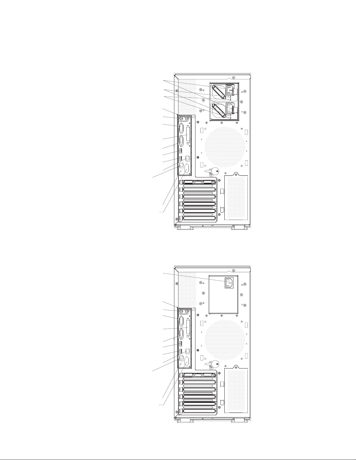
Rear view
The following illustration shows the LEDs and connectors on the rear of the
hot-swap power supply models with optional redundant power.
Power cords
AC power LEDs
DCpower LEDs
Mouse
Keyboard
Serial 1
(COM 1)
Parallel
Video
USB 4
USB 3
(RJ45) Ethernet 10/100/1000
(RJ45) Ethernet 10/100
(for Remote Supervisor Adapter II
SlimLine)
NMI button
Serial 2
(COM 2)
The following illustration shows the connectors on the rear of the non-hot-swap
power supply models.
Power cords
Mouse
Keyboard
Serial 1
(COM 1)
Parallel
Video
USB 4
USB 3
(RJ45) Ethernet 10/100/1000
(RJ45) Ethernet 10/100
(for Remote Supervisor Adapter II
SlimLine)
NMI button
Serial 2
(COM 2)
Chapter 1. Introduction 9
Page 28

Power-cord connector
Connect the power cord to this connector.
AC power LED
This green LED provides status information about the power supply. During
typical operation, both the ac and dc power LEDs are lit. For any other
combination of LEDs, see the Problem Determination and Service Guide on
the IBM System x3400 Documentation CD.
DC power LED
This green LED provides status information about the power supply. During
typical operation, both the ac and dc power LEDs are lit. For any other
combination of LEDs, see the Problem Determination and Service Guide on
the IBM System x3400 Documentation CD.
Mouse connector
Connect a mouse device to this connector.
Keyboard connector
Connect a PS/2 keyboard to this connector.
Serial 1 connector
Connect a 9-pin serial device to this connector.
Parallel connector
Connect a parallel device to this connector.
Video connector
Connect a monitor to this connector.
USB connectors
Connect USB devices to these connectors.
Ethernet connector
Use this connector to connect the server to a network.
Serial 2 connector
Connect a 9-pin serial device to this connector.
Ethernet transmit/receive activity LED
This LED is on the Ethernet connector. When this LED is lit, it indicates that
there is activity between the server and the network.
Ethernet link status LED
This LED is on the Ethernet connector. When this LED is lit, it indicates that
there is an active connection on the Ethernet port.
Remote Supervisor Adapter II SlimLine connector
Connect the optional Remote Supervisor Adapter II SlimLine card to this
connector.
10 System x3400 Types 7973, 7974, 7975, and 7976: Problem Determination and Service Guide
Page 29
Internal connectors, LEDs, and switches
The following illustrations show the connectors, light-emitting diodes (LEDs), and
switches on the system board. The illustrations might differ slightly from your
hardware.
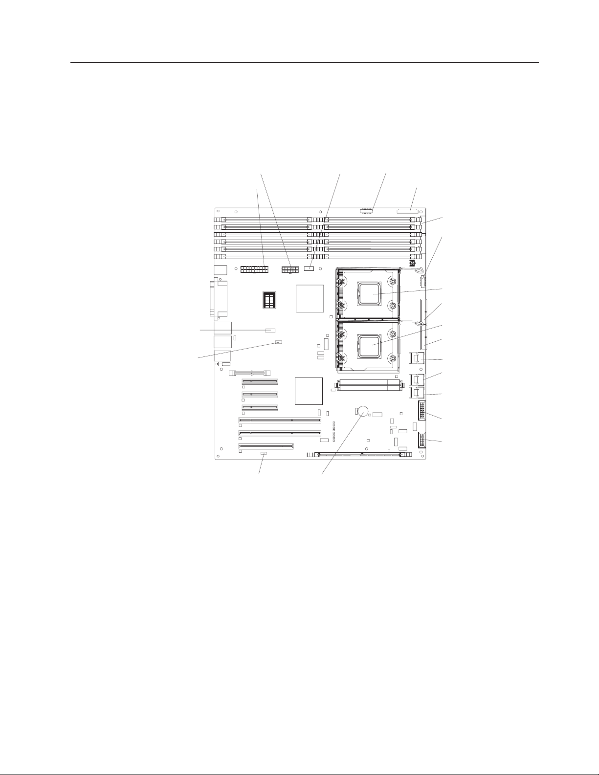
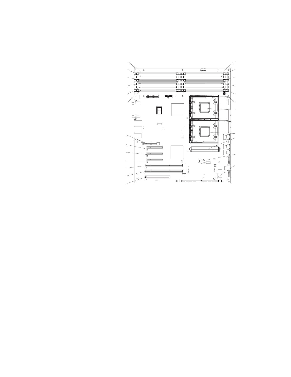
System-board internal connectors
The following illustration shows the internal connectors on the system board.
Powe r Powe r
Main power
USB tape
Front panel
Primary IDE
Front USB
Rear fan
COM 2
header
DIMM LEDs
6
5
4
3
2
1
12
11
10
9
8
7
Microprocessor 1
SAS/SATA backplane 1
power
Microprocessor 2
SAS/SATA backplane 2
power
Simple-swap SATA backplate
Hot-swap SAS/SATA 1
signal
Hot-swap SAS/SATA 2
signal
Hot-swap main fan
Hot-swap fan
(redundant)
BatteryWake on LAN
Chapter 1. Introduction 11
Page 30
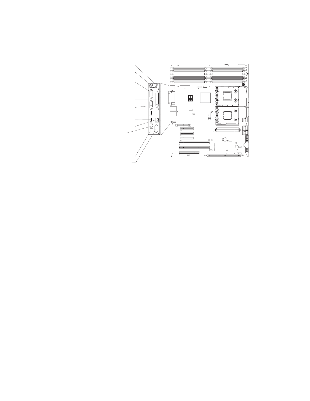
System-board external connectors
The following illustration shows the external input/output (I/O) connectors on the
system board.
Mouse
Keyboard
Serial 1
(COM 1)
Parallel
Video
USB 4
USB 3
(RJ45) Ethernet 10/100/1000
(RJ45) Ethernet 10/100
(for Remote Supervisor Adapter II
SlimLine)
NMI button
Serial 2
(COM 2)
DIMM LEDs
6
12
5
11
4
10
3
9
8
2
7
1
12 System x3400 Types 7973, 7974, 7975, and 7976: Problem Determination and Service Guide
Page 31
System-board option connectors
The following illustration shows the system-board connectors for user-installable
options.
Remote
Supervisor
Adapter II SlimLine
Slot 1, PCI Express x8 (x4)
Slot 2, PCI Express x8 (x8)
Slot 3, PCI Express x8 (x8)
Slot 4, PCI-X 64 bit/133 MHz
Slot 5, PCI-X 64 bit/133 MHz
Slot 6, PCI 32 bit/33 MHz
DIMM LEDs
DIMM 12DIMM 6
DIMM 11DIMM 5
DIMM 10DIMM 4
DIMM 9DIMM 3
DIMM 8DIMM 2
DIMM 7DIMM 1
6
12
5
11
4
10
3
9
8
2
7
1
Microprocessor 1
Microprocessor 2
VRM
Battery
ServeRAID
adapter
Chapter 1. Introduction 13
Page 32

System-board LEDs
The following illustration shows the LEDs on the system board.
Microprocessor 1
error LED
DIMM
error LEDs
1 through 12
Microprocessor
mismatch
LED
Slot 1
error LED
Slot 2
error LED
Slot 3
error LED
Slot 4
error LED
Slot 5
error LED
Slot 6
error LED
DIMM LEDs
6
5
4
3
2
1
12
11
10
9
8
7
Microprocessor 2
error LED
VRM error
LED
Battery LED
BMC heartbeat
LED
ServeRAID
error LED
14 System x3400 Types 7973, 7974, 7975, and 7976: Problem Determination and Service Guide
Page 33

System-board switches
The following illustration shows the switches on the system board.
DIMM LEDs
6
5
4
3
2
1
12
11
10
9
8
7
Boot block/Clear CMOS
The following table describes the function of each switch on the system board.
Table 3. System board switches
Switch number Description
1 Boot block:
v When this switch is on 1, this is normal mode.
v When this switch is toggled to On, this enables the
system to recover if the BIOS code becomes damaged.
See
“Recovering from a BIOS update failure” on page 72
for more information.
2 Clear CMOS:
v When this switch is on 2, this keeps the CMOS data.
This is normal mode.
v When this switch is toggled to On, this clears the CMOS
data, which clears the power-on password and
administrator password.
Chapter 1. Introduction 15
Page 34

16 System x3400 Types 7973, 7974, 7975, and 7976: Problem Determination and Service Guide
Page 35

Chapter 2. Diagnostics
This chapter describes the diagnostic tools that are available to help you solve
problems that might occur in the server.
If you cannot locate and correct the problem using the information in this chapter,
see “Getting help and technical assistance” on page 183 for more information.
Diagnostic tools
The following tools are available to help you diagnose and solve hardware-related
problems:
v POST beep codes, error messages, and error logs
The power-on self-test (POST) generates beep codes and messages to indicate
successful test completion or the detection of a problem. See “POST” for more
information.
v Troubleshooting tables
These tables list problem symptoms and actions to correct the problems. See
“Troubleshooting tables” on page 41.
v Server LEDs
Use the LEDs on the server to diagnose system errors quickly. See “Error LEDs”
on page 55 for more information.
v Diagnostic programs, messages, and error messages
The diagnostic programs are the primary method of testing the major
components of the server. The diagnostic programs are on the IBM Enhanced
Diagnostics CD that comes with the server. See “Diagnostic programs,
messages, and error codes” on page 58 for more information.
POST
When you turn on the server, it performs a series of tests to check the operation of
the server components and some optional devices in the server. This series of tests
is called the power-on self-test, or POST.
If a power-on password is set, you must type the password and press Enter, when
prompted, for POST to run.
If POST is completed without detecting any problems, a single beep sounds, and
the server startup is completed.
If POST detects a problem, more than one beep might sound, or an error message
is displayed. See “POST beep codes” on page 18 and “POST error codes” on page
24 for more information.
© Copyright IBM Corp. 2006 17
Page 36

POST beep codes
A beep code is a combination of short or long beeps or series of short beeps that
are separated by pauses. For example, a “1-2-3” beep code is one short beep, a
pause, two short beeps, and pause, and three short beeps. A beep code indicates
that POST has detected a problem. If no beep code sounds, see “No-beep
symptoms” on page 21.
The following table describes the beep codes and suggested actions to correct the
detected problems.
A single problem might cause more than one error message. When this occurs,
correct the cause of the first error message. The other error messages usually will
not occur the next time POST runs.
Exception: If there are multiple error codes that indicate a microprocessor error,
the error might be in a microprocessor or in a microprocessor socket. See
“Microprocessor problems” on page 47 for information about diagnosing
microprocessor problems.
v Follow the suggested actions in the order in which they are listed in the Action column until the problem
is solved.
v See Chapter 3, “Parts listing, System x3400 Types 7973, 7974, 7975 and 7976,” on page 87 to determine
which components are customer replaceable units (CRU) and which components are field replaceable
units (FRU).
v If an action step is preceded by “(Trained service technician only),” that step must be performed only by a
trained service technician.
Beep code Description Action
1-1-3 CMOS write/read test failed.
1-1-4 BIOS ROM checksum failed.
1-2-1 Programmable interval timer failed. (Trained service technician only) Replace the
1-2-2 DMA initialization failed. (Trained service technician only) Replace the
1-2-3 DMA page register write/read failed. (Trained service technician only) Replace the
1-2-4 RAM refresh verification failed.
1. Reseat the battery.
2. Replace the following components one at a
time, in the order shown, restarting the
server each time:
a. Battery
b. (Trained service technician only) System
board
1. Recover the BIOS code.
2. (Trained service technician only) Replace
the system board.
system board.
system board.
system board.
1. Reseat the DIMMs.
2. Replace the following components one at a
time, in the order shown, restarting the
server each time:
a. DIMMs
b. (Trained service technician only) System
board
18 System x3400 Types 7973, 7974, 7975, and 7976: Problem Determination and Service Guide
Page 37

v Follow the suggested actions in the order in which they are listed in the Action column until the problem
is solved.
v See Chapter 3, “Parts listing, System x3400 Types 7973, 7974, 7975 and 7976,” on page 87 to determine
which components are customer replaceable units (CRU) and which components are field replaceable
units (FRU).
v If an action step is preceded by “(Trained service technician only),” that step must be performed only by a
trained service technician.
Beep code Description Action
1-3-1 First 64 K RAM test failed.
1. Reseat the DIMMs.
2. Replace the following components one at a
time, in the order shown, restarting the
server each time:
a. DIMMs
b. (Trained service technician only) System
board
2-1-1 Secondary DMA register test failed. (Trained service technician only) Replace the
system board.
2-1-2 Primary DMA register test failed. (Trained service technician only) Replace the
system board.
2-1-3 Primary interrupt mask register test
failed.
2-1-4 Secondary interrupt mask register test
failed.
2-4-1 Video failed, system believed to be
operable.
(Trained service technician only) Replace the
system board.
(Trained service technician only) Replace the
system board.
(Trained service technician only) Replace the
system board.
3-1-1 Timer interrupt test failed. (Trained service technician only) Replace the
system board.
3-1-2 Timer 2 test failed. (Trained service technician only) Replace the
system board.
3-1-4 Time-of-day clock failed.
1. Reseat the battery.
2. Replace the following components one at a
time, in the order shown, restarting the
server each time:
a. Battery
b. (Trained service technician only) System
board
3-3-2 Critical SMBUS error occurred.
1. Reseat the DIMMs.
2. Replace the following components one at a
time, in the order shown, restarting the
server each time:
a. DIMMs
b. (Trained service technician only) System
board
Chapter 2. Diagnostics 19
Page 38

v Follow the suggested actions in the order in which they are listed in the Action column until the problem
is solved.
v See Chapter 3, “Parts listing, System x3400 Types 7973, 7974, 7975 and 7976,” on page 87 to determine
which components are customer replaceable units (CRU) and which components are field replaceable
units (FRU).
v If an action step is preceded by “(Trained service technician only),” that step must be performed only by a
trained service technician.
Beep code Description Action
3-3-3 No operational memory in system.
1. Make sure that the system board contains
the correct number and type of DIMMs;
install or reseat the DIMMS; then, restart
the server.
Important: In some memory
configurations, the 3-3-3 beep code might
sound during POST, followed by a blank
monitor screen. If this occurs and the Boot
Fail Count option in the Start Options of
the Configuration/Setup Utility program is
enabled, you must restart the server three
times to reset the configuration settings to
the default configuration (the memory
connector or bank of connectors enabled).
2. Replace the following components one at a
time, in the order shown, restarting the
server each time:
a. DIMMs
b. (Trained service technician only) System
board
Two short beeps Information only, configuration has
changed.
1. Run the Configuration/Setup Utility program.
2. Run the diagnostic programs.
20 System x3400 Types 7973, 7974, 7975, and 7976: Problem Determination and Service Guide
Page 39

No-beep symptoms
The following table describes situations in which no beep code sounds when POST
is completed.
v Follow the suggested actions in the order in which they are listed in the Action column until the problem
is solved.
v See Chapter 3, “Parts listing, System x3400 Types 7973, 7974, 7975 and 7976,” on page 87 to determine
which components are customer replaceable units (CRU) and which components are field replaceable
units (FRU).
v If an action step is preceded by “(Trained service technician only),” that step must be performed only by a
trained service technician.
No-beep symptom Description Action
No beeps occur, and the
server operates correctly.
No beeps occur, and
there is no video.
1. (Trained service technician only) Reseat the
front information panel LED cable.
2. (Trained service technician only) Replace
the front information panel LED assembly.
See “Solving undetermined problems” on page
84.
Chapter 2. Diagnostics 21
Page 40

Error logs
The POST error log contains the three most recent error codes and messages that
were generated during POST. The BMC log and the system-event log contain
messages that were generated during POST and all system status messages from
the service processor.
The following illustration shows an example of a BMC log entry.
BMC System Event Log
---------------------------------------------------------Get Next Entry
Get Previous Entry
Clear BMC SEL
Entry Number= 00005 / 00011
Record ID= 0005
Record Type= 02
Timestamp= 2005/01/25 16:15:17
Entry Details: Generator ID= 0020
Sensor Type= 04
Assertion Event
Fan
Threshold
Lower Non-critical - going high
Sensor Number= 40
Event Direction/Type= 01
Event Data= 52 00 1A
The BMC log is limited in size. When the log is full, new entries will not overwrite
existing entries; therefore, you must periodically clear the BMC log through the
Configuration/Setup Utility program (the menu choices are described in the User’s
Guide). When you are troubleshooting an error, be sure to clear the BMC log so
that you can find current errors more easily.
Important: After you complete a repair or correct an error, clear the BMC log to
turn off the system-error LED on the front of the server.
Entries that are written to the BMC log during the early phase of POST show an
incorrect date and time as the default time stamp; however, the date and time are
corrected as POST continues.
Each BMC log entry appears on its own page. To display all of the data for an entry,
use the Up Arrow (↑) and Down Arrow (↓) keys or the Page Up and Page Down
keys. To move from one entry to the next, select Get Next Entry or Get Previous
Entry.
The log indicates an assertion event when an event has occurred. It indicates a
deassertion event when the event is no longer occurring.
Some of the error codes and messages in the BMC log are abbreviated.
If you view the BMC log through the Web interface of the optional Remote
Supervisor Adapter II SlimLine, the messages can be translated.
You can view the contents of the POST error log, the BMC log, and the
system-error log from the Configuration/Setup Utility program. You can view the
22 System x3400 Types 7973, 7974, 7975, and 7976: Problem Determination and Service Guide
Page 41

contents of the BMC log also from the diagnostic programs. For complete
information about using the Configuration/Setup Utility program, see the User’s
Guide.
Viewing error logs from the Configuration/Setup Utility program
For complete information about using the Configuration/Setup Utility program, see
the User’s Guide.
To view the error logs, complete the following steps:
1. Turn on the server.
2. When the prompt Press F1 for Configuration/Setup appears, press F1. If you
have set both a power-on password and an administrator password, you must
type the administrator password to view the error logs.
3. Use one of the following procedures:
v To view the POST error log, select Error Logs → POST Error Log.
v To view the system error log (available only if an optional Remote Supervisor
Adapter II SlimLine is installed), select Error Logs → System Event/Error
Log.
v To view the BMC log, select Advanced Setup → IPMI → System Event Log.
Viewing the BMC log from the diagnostic programs
The BMC log contains the same information, whether it is viewed from the
Configuration/Setup Utility program or from the diagnostic programs.
For information about using the diagnostic programs, see “Running the diagnostic
programs” on page 58.
To view the BMC log, complete the following steps:
1. If the server is running, turn off the server and all attached devices.
2. Turn on all attached devices; then, turn on the server.
3. When the prompt F1 for Configuration/Setup appears, press F1.
4. When the Configuration/Setup Utility menu appears, select Start Options.
5. From the Start Options menu, select Startup Sequence Options.
6. Note the device that is selected as the first startup device. Later, you must
restore this setting.
7. Select the CD-ROM or DVD-ROM (depending on the drive in your server) as
the first startup device.
8. Press Esc two times to return to the Configuration/Setup Utility menu.
9. Insert the IBM Enhanced Diagnostics CD into the CD or DVD drive.
10. Select Save & Exit Setup and follow the prompts. The diagnostics will load.
11. From the top of the screen, select Hardware Info.
12. From the list, select BMC Log.
Chapter 2. Diagnostics 23
Page 42
POST error codes
The following table describes the POST error codes and suggested actions to
correct the detected problems.
v Follow the suggested actions in the order in which they are listed in the Action column until the problem
is solved.
v See Chapter 3, “Parts listing, System x3400 Types 7973, 7974, 7975 and 7976,” on page 87 to determine
which components are customer replaceable units (CRU) and which components are field replaceable
units (FRU).
v If an action step is preceded by “(Trained service technician only),” that step must be performed only by a
trained service technician.
Error code Description Action
062 Three consecutive boot failures using the
default configuration.
101 Tick timer internal interrupt failure. (Trained service technician only) Replace the system
102 Internal timer channel 2 test failure. (Trained service technician only) Replace the system
151 Real-time clock error.
161 Real-time clock battery failure.
162 Invalid configuration information or CMOS
random-access memory (RAM) checksum
failure.
1. Update the system firmware to the latest level
(see “Updating the firmware” on page 165).
2. (Trained service technician only) Replace the
system board.
board.
board.
1. Reseat the battery.
2. Replace the following components one at a time,
in the order shown, restarting the server each
time:
a. Battery
b. (Trained service technician only) System
board
1. Reseat the battery.
2. Replace the following components one at a time,
in the order shown, restarting the server each
time:
a. Battery
b. (Trained service technician only) System
board
1. Run the Configuration/Setup Utility program,
select Load Default Settings, and save the
settings.
2. Reseat the following components:
a. Battery
b. Failing device (If the device is a FRU, it must
be reseated by a trained service technician
only.)
Replace the following components one at a time,
3.
in the order shown, restarting the server each
time:
a. Battery
b. Failing device (If the device is a FRU, it must
be replaced by a trained service technician
only.)
c. (Trained service technician only) System
board
24 System x3400 Types 7973, 7974, 7975, and 7976: Problem Determination and Service Guide
Page 43

v Follow the suggested actions in the order in which they are listed in the Action column until the problem
is solved.
v See Chapter 3, “Parts listing, System x3400 Types 7973, 7974, 7975 and 7976,” on page 87 to determine
which components are customer replaceable units (CRU) and which components are field replaceable
units (FRU).
v If an action step is preceded by “(Trained service technician only),” that step must be performed only by a
trained service technician.
Error code Description Action
163 Time of day not set.
1. Run the Configuration/Setup Utility program,
select Load Default Settings, make sure that the
date and time are correct, and save the settings.
2. Reseat the battery.
3. Replace the following components one at a time,
in the order shown, restarting the server each
time:
a. Battery
b. (Trained service technician only) System
board
175 Service processor flash code damaged or
not loaded.
1. Restart the server.
2. Update the optional Remote Supervisor Adapter II
SlimLine firmware (see “Updating the firmware”
on page 165.
3. Replace the optional Remote Supervisor Adapter
II SlimLine.
4. (Trained service technician only) Replace the
system board.
178 Security hardware error.
1. Run the Configuration/Setup Utility program,
select Load Default Settings, and save the
settings.
2. Reseat the optional Remote Supervisor Adapter II
SlimLine.
3. Replace the following components one at a time,
in the order shown, restarting the server each
time:
a. Optional Remote Supervisor Adapter II
SlimLine
b. (Trained service technician only) System
board
184 Power-on password damaged.
1. Run the Configuration/Setup Utility program,
select Load Default Settings, and save the
settings.
2. Reseat the battery.
3. Replace the following components one at a time,
in the order shown, restarting the server each
time:
a. Battery
b. (Trained service technician only) System
board
Chapter 2. Diagnostics 25
Page 44
v Follow the suggested actions in the order in which they are listed in the Action column until the problem
is solved.
v See Chapter 3, “Parts listing, System x3400 Types 7973, 7974, 7975 and 7976,” on page 87 to determine
which components are customer replaceable units (CRU) and which components are field replaceable
units (FRU).
v If an action step is preceded by “(Trained service technician only),” that step must be performed only by a
trained service technician.
Error code Description Action
187 VPD serial number not set.
1. Set the serial number by updating the BIOS code
level (see “Updating the firmware” on page 165).
2. Reseat the optional Remote Supervisor Adapter II
SlimLine.
3. (Trained service technician only) Replace the
system board.
188 Bad VPD CRC #2.
1. Restart the server.
2. Update the firmware (see “Updating the firmware”
on page 165.
3. Reseat the optional Remote Supervisor Adapter II
SlimLine.
4. (Trained service technician only) Replace the
system board.
189 Three attempts were made to access the
server with an incorrect password.
Restart the server and enter the administrator
password; then, run the Configuration/Setup Utility
program and change the power-on password.
196 Processor cache mismatch.
1. Make sure that all microprocessors have the
same cache size (see “Using the
Configuration/Setup Utility program” on page 166.
2. Update the BIOS code (see “Updating the
firmware” on page 165).
3. (Trained service technician only) Reseat
microprocessor.
4. (Trained service technician only) Replace
microprocessor.
198 Processor speed mismatch.
1. Make sure that all microprocessors have the
same speed (see “Using the Configuration/Setup
Utility program” on page 166.
2. Update the BIOS code (see “Updating the
firmware” on page 165).
3. (Trained service technician only) Reseat
microprocessor.
4. (Trained service technician only) Replace
microprocessor.
289 A DIMM has been disabled by the user or
by the system.
1. If the DIMM was disabled by the user, run the
Configuration/Setup Utility program and enable
the DIMM.
2. Make sure that the DIMM is installed correctly
(see “Installing a memory module” on page 120).
3. Reseat the DIMM.
4. Replace the DIMM.
26 System x3400 Types 7973, 7974, 7975, and 7976: Problem Determination and Service Guide
Page 45

v Follow the suggested actions in the order in which they are listed in the Action column until the problem
is solved.
v See Chapter 3, “Parts listing, System x3400 Types 7973, 7974, 7975 and 7976,” on page 87 to determine
which components are customer replaceable units (CRU) and which components are field replaceable
units (FRU).
v If an action step is preceded by “(Trained service technician only),” that step must be performed only by a
trained service technician.
Error code Description Action
301 Keyboard or keyboard controller error.
1. If you have installed a USB keyboard, run the
Configuration/Setup Utility program and enable
keyboardless operation to prevent the POST error
message 301 from being displayed during startup.
2. Reseat the keyboard cable.
3. Replace the following components one at a time,
in the order shown, restarting the server each
time:
a. Keyboard
b. (Trained service technician only) System
board
303 Keyboard controller failure.
1. Reseat the keyboard.
2. Replace the keyboard.
3. (Trained service technician only) Replace the
system board.
1600 The service processor is not functioning.
Note: Depending on which device is
installed, the service processor is the
optional Remote Supervisor Adapter II
SlimLine or the BMC.
1. If the optional Remote Supervisor Adapter II
SlimLine is installed:
a. Update the Remote Supervisor Adapter II
SlimLine firmware.
b. Replace the Remote Supervisor II SlimLine.
Update the BMC firmware (see “Updating the
2.
firmware” on page 165).
3. (Trained service technician only) Replace the
system board.
1604 Machine type mismatch.
1. Run the Configuration/Setup Utility program,
select Load Default Settings, and save the
settings.
2. Update the BIOS code and BMC firmware (see
“Updating the firmware” on page 165).
3. (Trained service technician only) Replace the
system board.
Chapter 2. Diagnostics 27
Page 46

v Follow the suggested actions in the order in which they are listed in the Action column until the problem
is solved.
v See Chapter 3, “Parts listing, System x3400 Types 7973, 7974, 7975 and 7976,” on page 87 to determine
which components are customer replaceable units (CRU) and which components are field replaceable
units (FRU).
v If an action step is preceded by “(Trained service technician only),” that step must be performed only by a
trained service technician.
Error code Description Action
1762 Fixed disk configuration error.
1. Run the Configuration/Setup Utility program,
select Load Default Settings, and save the
settings.
2. Reseat the following components:
v SAS cables
v SAS hard disk drive
v SAS backplane
Replace the components listed in step 2 one at a
3.
time, in the order shown, restarting the server
each time.
4. (Trained service technician only) Replace the
system board.
28 System x3400 Types 7973, 7974, 7975, and 7976: Problem Determination and Service Guide
Page 47

v Follow the suggested actions in the order in which they are listed in the Action column until the problem
is solved.
v See Chapter 3, “Parts listing, System x3400 Types 7973, 7974, 7975 and 7976,” on page 87 to determine
which components are customer replaceable units (CRU) and which components are field replaceable
units (FRU).
v If an action step is preceded by “(Trained service technician only),” that step must be performed only by a
trained service technician.
Error code Description Action
178x Fixed disk error.
Note: x is the drive that has the error.
1. Run the hard disk drive diagnostic tests on drive
x (see “Running the diagnostic programs” on
page 58.
2. Reseat the hard disk drive cables.
3. Replace the hard disk drive cables.
4. Run the hard disk drive diagnostics tests on drive
x.
5. Reseat the following components, depending on
the server model:
v Hot-swap and non-hot-swap models:
a. Hard disk drive x
b. Hard disk drive x cable
c. Optional adapter cable
d. SAS/SATA backplane
Simple-swap models:
v
a. Hard disk drive x
b. Hard disk drive x cable
c. Optional adapter cable
d. SATA backplate
Replace the following components one at a time,
6.
depending on the server model, in the order
shown, restarting the server each time:
v Hot-swap and non-hot-swap models:
a. Hard disk drive x
b. Hard disk drive cable
c. Optional adapter cable
d. SAS/SATA backplane
Simple-swap models:
v
a. Hard disk drive x
b. Hard disk drive x cable
c. Optional adapter cable
d. SATA backplate
(Trained service technician only) Replace the
7.
system board.
1800 Unavailable PCI hardware interrupt.
1. Run the Configuration/Setup Utility program and
adjust the adapter settings.
2. Remove each adapter one at a time, restarting
the server each time, until the problem is isolated.
Chapter 2. Diagnostics 29
Page 48

v Follow the suggested actions in the order in which they are listed in the Action column until the problem
is solved.
v See Chapter 3, “Parts listing, System x3400 Types 7973, 7974, 7975 and 7976,” on page 87 to determine
which components are customer replaceable units (CRU) and which components are field replaceable
units (FRU).
v If an action step is preceded by “(Trained service technician only),” that step must be performed only by a
trained service technician.
Error code Description Action
1801 A PCI adapter has requested memory
resources that are not available.
1. Make sure that no devices have been disabled in
the Configuration/Setup Utility program.
2. Change the order of the adapters in the PCI,
PCI-X, or PCI Express slots. Make sure that the
startup (boot) device is positioned early in the
scanning order. (For information about the
scanning order, see the User’s Guide on the IBM
System x3400 Documentation CD).
3. Make sure that the settings for the adapter and all
other adapters in the Configuration/Setup Utility
program are correct. If the memory resource
settings are not correct, change them.
4. If all memory resources are being used, remove
an adapter to make memory available to the
adapter. Disabling the BIOS on the adapter
should correct the error. See the documentation
that comes with the adapter.
1802 No more I/O space is available for a PCI,
PCI-X, or PCI Express adapter.
1. Make sure that the settings for the adapter and all
other adapters in the Configuration/Setup Utility
program are correct.
2. If the error code indicates a particular PCI, PCI-X,
or PCI Express slot or device, remove that
device.
3. Reseat each adapter.
4. Replace the following components one at a time,
in the order shown, restarting the server each
time:
a. Adapter
b. (Trained service technician only) System
board
1803 No more memory (above 1 MB for a PCI,
PCI-X, or PCI Express adapter).
1. Make sure that the settings for the adapter and all
other adapters in the Configuration/Setup Utility
program are correct.
2. If the error code indicates a particular PCI, PCI-X,
or PCI Express slot or device, remove that
device.
3. Reseat each adapter.
4. Replace the following components one at a time,
in the order shown, restarting the server each
time:
a. Adapter
b. (Trained service technician only) System
board
30 System x3400 Types 7973, 7974, 7975, and 7976: Problem Determination and Service Guide
Page 49

v Follow the suggested actions in the order in which they are listed in the Action column until the problem
is solved.
v See Chapter 3, “Parts listing, System x3400 Types 7973, 7974, 7975 and 7976,” on page 87 to determine
which components are customer replaceable units (CRU) and which components are field replaceable
units (FRU).
v If an action step is preceded by “(Trained service technician only),” that step must be performed only by a
trained service technician.
Error code Description Action
1804 No more memory (below 1 MB for a PCI,
PCI-X, or PCI Express adapter).
1. Make sure that the settings for the adapter and all
other adapters in the Configuration/Setup Utility
program are correct.
2. If the error code indicates a particular PCI, PCI-X,
or PCI Express slot or device, remove that
device.
3. Reseat each adapter.
4. Replace the following components one at a time,
in the order shown, restarting the server each
time:
a. Adapter
b. (Trained service technician only) System
board
1805 PCI option ROM checksum error.
1. Remove the failing adapter.
2. Reseat each adapter.
3. Replace the following components one at a time,
in the order shown, restarting the server each
time:
a. Adapter
b. (Trained service technician only) System
board
1806 PCI built-in self-test failure.
1. Make sure that the settings for the adapter and all
other adapters in the Configuration/Setup Utility
program are correct.
2. If the error code indicates a particular PCI, PCI-X,
or PCI Express slot or device, remove that
device.
3. Reseat each adapter.
4. Replace the following components one at a time,
in the order shown, restarting the server each
time:
a. Adapter
b. (Trained service technician only) System
board
Chapter 2. Diagnostics 31
Page 50

v Follow the suggested actions in the order in which they are listed in the Action column until the problem
is solved.
v See Chapter 3, “Parts listing, System x3400 Types 7973, 7974, 7975 and 7976,” on page 87 to determine
which components are customer replaceable units (CRU) and which components are field replaceable
units (FRU).
v If an action step is preceded by “(Trained service technician only),” that step must be performed only by a
trained service technician.
Error code Description Action
1807, 1808 General PCI error.
1. Make sure that no devices have been disabled in
the Configuration/Setup Utility program.
2. Reseat the failing adapter.
Note: If an error LED is lit for a specific adapter,
reseat that adapter first; if no LEDs are lit, reseat
each adapter one at a time, restarting the server
each time, to isolate the failing adapter.
3. Replace the following components one at a time,
in the order shown, restarting the server each
time:
a. Adapter
b. (Trained service technician only) System
board
1810 PCI error.
1. Make sure that no devices have been disabled in
the Configuration/Setup Utility program.
2. Remove the adapters from the PCI, PCI-X, or PCI
Express slots.
3. Reseat the failing adapter.
Note: If an error LED is lit on an adapter, reseat
that adapter first; if no LEDs are lit, reseat each
adapter one at a time, restarting the server each
time, to isolate the failing adapter.
4. Replace the following components one at a time,
in the order shown, restarting the server each
time:
a. Failing adapter
b. (Trained service technician only) System
board
32 System x3400 Types 7973, 7974, 7975, and 7976: Problem Determination and Service Guide
Page 51

v Follow the suggested actions in the order in which they are listed in the Action column until the problem
is solved.
v See Chapter 3, “Parts listing, System x3400 Types 7973, 7974, 7975 and 7976,” on page 87 to determine
which components are customer replaceable units (CRU) and which components are field replaceable
units (FRU).
v If an action step is preceded by “(Trained service technician only),” that step must be performed only by a
trained service technician.
Error code Description Action
1962 A hard disk drive does not contain a valid
boot sector.
1. Make sure that a bootable operating system is
installed.
2. Run the hard disk drive diagnostic tests.
3. Reseat the following components, depending on
the server model:
v Hot-swap and non-hot-swap models:
a. Hard disk drive
b. Hard disk drive cable
c. Optional adapter cable
d. SAS/SATA backplane
Simple-swap models:
v
a. Hard disk drive
b. Hard disk drive cable
c. Optional adapter cable
d. SATA backplate
Replace the following components one at a time,
4.
depending on the server model, in the order
shown, restarting the server each time:
v Hot-swap and non-hot-swap models:
a. Hard disk drive
b. Hard disk drive cable
c. Optional adapter cable
d. SAS/SATA backplane
v
Simple-swap models:
a. Hard disk drive
b. Hard disk drive cable
c. Optional adapter cable
d. SATA backplate
(Trained service technician only) Replace the
5.
system board.
2462 Video configuration error occurred.
1. Reseat the video adapter, if one is installed.
2. (Trained service technician only) Replace the
system board.
Chapter 2. Diagnostics 33
Page 52

v Follow the suggested actions in the order in which they are listed in the Action column until the problem
is solved.
v See Chapter 3, “Parts listing, System x3400 Types 7973, 7974, 7975 and 7976,” on page 87 to determine
which components are customer replaceable units (CRU) and which components are field replaceable
units (FRU).
v If an action step is preceded by “(Trained service technician only),” that step must be performed only by a
trained service technician.
Error code Description Action
5962 IDE CD or DVD drive configuration error.
1. Run the Configuration/Setup Utility program and
load the default settings (see “Using the
Configuration/Setup Utility program” on page
166).
2. Reseat the following components:
v CD or DVD drive cable
v CD or DVD drive
Replace the components listed in step 2 one at a
3.
time, in the order shown, restarting the server
each time.
4. (Trained service technician only) Replace the
system board
8603 Pointing-device error.
1. Reseat the pointing device.
2. Replace the following components one at a time,
in the order shown, restarting the server each
time:
a. Pointing device
b. (Trained service technician only) System
board
00012000 Processor machine check error.
1. (Trained service technician only) Reseat the
microprocessor.
2. Replace the following components one at a time,
in the order shown, restarting the server each
time:
a. (Trained service technician only)
Microprocessor
b. (Trained service technician only) System
board
00019501 Processor 1 is not functioning; check VRM
and processor LEDs.
1. (Trained service technician only) Reseat
microprocessor 1.
2. Replace the following components one at a time,
in the order shown, restarting the server each
time:
a. (Trained service technician only)
Microprocessor 1
b. (Trained service technician only) System
board
34 System x3400 Types 7973, 7974, 7975, and 7976: Problem Determination and Service Guide
Page 53

v Follow the suggested actions in the order in which they are listed in the Action column until the problem
is solved.
v See Chapter 3, “Parts listing, System x3400 Types 7973, 7974, 7975 and 7976,” on page 87 to determine
which components are customer replaceable units (CRU) and which components are field replaceable
units (FRU).
v If an action step is preceded by “(Trained service technician only),” that step must be performed only by a
trained service technician.
Error code Description Action
00019502 Processor 2 is not functioning; check VRM
and processor LEDs.
1. (Trained service technician only) Reseat
microprocessor 2.
2. Replace the following components one at a time,
in the order shown, restarting the server each
time:
a. (Trained service technician only)
Microprocessor 2
b. (Trained service technician only) System
board
00019701 Processor 1 failed the built-in self-test
(BIST).
1. (Trained service technician only) Reseat
microprocessor 1.
2. Replace the following components one at a time,
in the order shown, restarting the server each
time:
a. (Trained service technician only)
Microprocessor 1
b. (Trained service technician only) System
board
00019702 Processor 2 failed the built-in self-test
(BIST).
1. (Trained service technician only) Reseat
microprocessor 2.
2. Replace the following components one at a time,
in the order shown, restarting the server each
time:
a. (Trained service technician only)
Microprocessor 2
b. (Trained service technician only) System
board
01298001 No update data for processor 1.
1. Make sure that all microprocessors have the
same cache size (see “Using the
Configuration/Setup Utility program” on page 166.
2. Update the BIOS code (see “Updating the
firmware” on page 165).
3. (Trained service technician only) Reseat
microprocessor 1.
4. (Trained service technician only) Replace
microprocessor 1.
Chapter 2. Diagnostics 35
Page 54

v Follow the suggested actions in the order in which they are listed in the Action column until the problem
is solved.
v See Chapter 3, “Parts listing, System x3400 Types 7973, 7974, 7975 and 7976,” on page 87 to determine
which components are customer replaceable units (CRU) and which components are field replaceable
units (FRU).
v If an action step is preceded by “(Trained service technician only),” that step must be performed only by a
trained service technician.
Error code Description Action
01298002 No update data for processor 2.
1. Make sure that all microprocessors have the
same cache size (see “Using the
Configuration/Setup Utility program” on page 166.
2. Update the BIOS code (see “Updating the
firmware” on page 165).
3. (Trained service technician only) Reseat
microprocessor 2.
4. (Trained service technician only) Replace
microprocessor 2.
01298101 Bad update data for processor 1.
1. Make sure that all microprocessors have the
same cache size (see “Using the
Configuration/Setup Utility program” on page 166.
2. Update the BIOS code again (see “Updating the
firmware” on page 165).
3. (Trained service technician only) Reseat the
microprocessor.
4. (Trained service technician only) Replace the
microprocessor.
01298102 Bad update data for processor 2.
1. Make sure that all microprocessors have the
same cache size (see “Using the
Configuration/Setup Utility program” on page 166.
2. Update the BIOS code (see “Updating the
firmware” on page 165).
3. (Trained service technician only) Reseat
microprocessor 2.
4. (Trained service technician only) Replace
microprocessor 2.
01298200 Processor speed mismatch. Make sure that all microprocessors have the same
cache size (see “Using the Configuration/Setup Utility
program” on page 166.
36 System x3400 Types 7973, 7974, 7975, and 7976: Problem Determination and Service Guide
Page 55

v Follow the suggested actions in the order in which they are listed in the Action column until the problem
is solved.
v See Chapter 3, “Parts listing, System x3400 Types 7973, 7974, 7975 and 7976,” on page 87 to determine
which components are customer replaceable units (CRU) and which components are field replaceable
units (FRU).
v If an action step is preceded by “(Trained service technician only),” that step must be performed only by a
trained service technician.
Error code Description Action
I9990301 Hard disk drive boot sector error.
1. Reseat the following components, depending on
the server model:
v Hot-swap and non-hot-swap models:
a. Hard disk drive
b. Hard disk drive cable
c. Optional adapter cable
d. SAS/SATA backplane
Simple-swap models:
v
a. Hard disk drive
b. Hard disk drive cable
c. Optional adapter cable
d. SATA backplate
Replace the following components one at a time,
2.
depending on the server model, in the order
shown, restarting the server each time:
v Hot-swap and non-hot-swap models:
a. Hard disk drive
b. Hard disk drive cable
c. Optional adapter cable
d. SAS/SATA backplane
Simple-swap models:
v
a. Hard disk drive
b. Hard disk drive cable
c. Optional adapter cable
d. SATA backplate
(Trained service technician only) Replace the
3.
system board.
Chapter 2. Diagnostics 37
Page 56

v Follow the suggested actions in the order in which they are listed in the Action column until the problem
is solved.
v See Chapter 3, “Parts listing, System x3400 Types 7973, 7974, 7975 and 7976,” on page 87 to determine
which components are customer replaceable units (CRU) and which components are field replaceable
units (FRU).
v If an action step is preceded by “(Trained service technician only),” that step must be performed only by a
trained service technician.
Error code Description Action
I9990305 An operating system was not found.
1. Make sure that a bootable operating system is
installed. To determine whether an operating
system is one of the devices in the startup
sequence, run the Configuration/Setup Utility
program (see the User’s Guide on the IBM
System x3400 Documentation CD).
2. Run the hard disk drive diagnostic tests.
3. Reseat the following components, depending on
the server model:
v Hot-swap models:
a. Hard disk drive
b. Hard disk drive cable
c. Hard disk drive backplane
Simple-swap models:
v
a. Hard disk drive
b. Hard disk drive cable
Replace the following components one at a time,
4.
depending on the server model, in the order
shown, restarting the server each time:
v Hot-swap models:
a. Hard disk drive
b. Hard disk drive cable
c. Hard disk drive backplane
Simple-swap models:
v
a. Hard disk drive
b. Hard disk drive cable
(Trained service technician only) Replace the
5.
system board.
I9990650 AC power has been restored.
1. Reseat the power cords.
2. Check for interruption of the external power.
3. Replace the power cords.
4. For hot-swap models, replace the power supply
backplane.
38 System x3400 Types 7973, 7974, 7975, and 7976: Problem Determination and Service Guide
Page 57

Checkout procedure
The checkout procedure is the sequence of tasks that you should follow to
diagnose a problem in the server.
About the checkout procedure
Before performing the checkout procedure for diagnosing hardware problems,
review the following information:
v Read the safety information that begins on page vii.
v The diagnostic programs provide the primary methods of testing the major
components of the server, such as the system board, ethernet controller,
keyboard, mouse (pointing device), serial ports, and hard disk drives. You can
also use them to test some external devices. If you are not sure whether a
problem is caused by the hardware or by the software, you can use the
diagnostic programs to confirm that the hardware is working correctly.
v When you run the diagnostic programs, a single problem might cause more than
one error message. When this happens, correct the cause of the first error
message. The other error messages usually will not occur the next time you run
the diagnostic programs.
Exception: If there are multiple error codes or LEDs that indicate a
microprocessor error, the error might be in a microprocessor or in a
microprocessor socket. See “Microprocessor problems” on page 47 for
information about diagnosing microprocessor problems.
v Before running the diagnostic programs, you must determine whether the failing
server is part of a shared hard disk drive cluster (two or more servers sharing
external storage devices). If it is part of a cluster, you can run all diagnostic
programs except the ones that test the storage unit (that is, a hard disk drive in
the storage unit) or the storage adapter that is attached to the storage unit. The
failing server might be part of a cluster if any of the following conditions is true:
– You have identified the failing server as part of a cluster (two or more servers
sharing external storage devices).
– One or more external storage units are attached to the failing server and at
least one of the attached storage units is also attached to another server or
unidentifiable device.
– One or more servers are located near the failing server.
Important:
If the server is part of a shared hard disk drive cluster, run one test
at a time. Do not run any suite of tests, such as “quick” or “normal” tests,
because this might enable the hard disk drive diagnostic tests.
v If the server is halted and a POST error code is displayed, see “Error logs” on
page 22. If the server is halted and no error message is displayed, see
“Troubleshooting tables” on page 41 and “Solving undetermined problems” on
page 84.
v For information about power-supply problems, see “Solving power problems” on
page 82.
v For intermittent problems, check the error log; see “Error logs” on page 22 and
“Diagnostic programs, messages, and error codes” on page 58.
Chapter 2. Diagnostics 39
Page 58

Performing the checkout procedure
To perform the checkout procedure, complete the following steps:
1. Is the server part of a cluster?
v No: Go to step 2.
v Yes: Shut down all failing servers that are related to the cluster. Go to step 2.
2. Complete the following steps:
a. Turn off the server and all external devices.
b. Check all cables and power cords.
c. Set all display controls to the middle positions.
d. Turn on all external devices.
e. Turn on the server. If the server does not start, see “Troubleshooting tables”
on page 41.
f. Check the system-error LED on the control panel. If it is lit, check the LEDs
on the system board (see “Error LEDs” on page 55).
Important: If the system-error LED on the front of the server is lit but there
are no other error indications, clear the BMC log. This log does not clear
itself, and if it begins to fill up, the system-error LED will be lit. Also, after you
complete a repair or correct an error, clear the BMC log to turn off the
system-error LED on the front of the server.
g. Check for the following results:
v Successful completion of POST, indicated by a single beep
v Successful completion of startup, indicated by a readable display of the
operating-system desktop
Did a single beep sound and are there readable instructions on the main menu,
3.
or was a POST error code displayed?
v Yes: Find the beep code or error code in “POST beep codes” on page 18 or
“POST error codes” on page 24; if necessary, see “Solving undetermined
problems” on page 84.
v No: Find the failure symptom in “Troubleshooting tables” on page 41; if
necessary, run the diagnostic programs (see “Running the diagnostic
programs” on page 58).
– If you receive an error, see “Diagnostic error codes” on page 60.
– If the diagnostic programs were completed successfully and you still
suspect a problem, see “Solving undetermined problems” on page 84.
Checkpoint codes (trained service technicians only)
A checkpoint code identifies the check that was occurring when the server stopped;
it does not provide error codes or suggest replacement components. Checkpoint
codes are shown on the checkpoint display, which is on the system board. By using
the checkpoint display, you do not have to wait for the video to initialize each time
that you restart the server.
There are two types of checkpoint codes: complex programmable logic device
(CPLD) hardware checkpoint codes and BIOS checkpoint codes. The BIOS
checkpoint codes might change when the BIOS code is updated.
40 System x3400 Types 7973, 7974, 7975, and 7976: Problem Determination and Service Guide
Page 59

Troubleshooting tables
Use the troubleshooting tables to find solutions to problems that have identifiable
symptoms.
If you cannot find the problem in these tables, see “Running the diagnostic
programs” on page 58 for information about testing the server.
If you have just added new software or a new optional device and the server is not
working, complete the following steps before using the troubleshooting tables:
1. Check the LEDs on the control panel or the system board (see “Error LEDs” on
page 55).
2. Remove the software or device that you just added.
3. Run the diagnostic tests to determine whether the server is running correctly.
4. Reinstall the new software or new device.
CD or DVD drive problems
v Follow the suggested actions in the order in which they are listed in the Action column until the problem
is solved.
v See Chapter 3, “Parts listing, System x3400 Types 7973, 7974, 7975 and 7976,” on page 87 to determine
which components are customer replaceable units (CRU) and which components are field replaceable
units (FRU).
v If an action step is preceded by “(Trained service technician only),” that step must be performed only by a
trained service technician.
Symptom Action
The CD or DVD drive is not
recognized.
A CD or DVD is not working
correctly.
1. Make sure that:
v The IDE channel to which the CD or DVD drive is attached (primary or
secondary) is enabled in the Configuration/Setup Utility program.
v All cables and jumpers are installed correctly.
v The correct device driver is installed for the CD or DVD drive.
Run the CD or DVD drive diagnostic programs.
2.
3. Reseat the CD or DVD drive cable.
4. Replace the following components one at a time, in the order shown, restarting
the server each time:
a. CD or DVD drive cable
b. CD or DVD drive
c. (Trained service technician only) System board
1. Clean the CD or DVD.
2. Run the CD or DVD drive diagnostic programs.
3. Reseat the CD or DVD drive cable.
4. Replace the following components one at a time, in the order shown, restarting
the server each time:
a. CD or DVD drive cable
b. CD or DVD drive
Chapter 2. Diagnostics 41
Page 60

v Follow the suggested actions in the order in which they are listed in the Action column until the problem
is solved.
v See Chapter 3, “Parts listing, System x3400 Types 7973, 7974, 7975 and 7976,” on page 87 to determine
which components are customer replaceable units (CRU) and which components are field replaceable
units (FRU).
v If an action step is preceded by “(Trained service technician only),” that step must be performed only by a
trained service technician.
Symptom Action
The CD or DVD drive tray is not
working.
1. Make sure that the server is turned on.
2. Insert the end of a straightened paper clip into the manual tray-release
opening.
3. Reseat the CD or DVD drive cable.
4. Replace the following components one at a time, in the order shown, restarting
the server each time:
a. CD or DVD drive cable
b. CD or DVD drive
Diskette drive problems
v Follow the suggested actions in the order in which they are listed in the Action column until the problem
is solved.
v See Chapter 3, “Parts listing, System x3400 Types 7973, 7974, 7975 and 7976,” on page 87 to determine
which components are customer replaceable units (CRU) and which components are field replaceable
units (FRU).
v If an action step is preceded by “(Trained service technician only),” that step must be performed only by a
trained service technician.
Symptom Action
The optional diskette drive
activity LED stays lit, or the
server bypasses the diskette
drive.
v If there is a diskette in the drive, make sure that:
– The diskette drive cables are correctly and securely connected.
– The diskette drive is enabled in the Configuration/Setup Utility program.
– The diskette is good and not damaged. (Try another diskette if you have
one.)
– The diskette is inserted correctly in the drive.
– The diskette contains the necessary files to start the server.
– Your software program is working properly.
To prevent diskette drive read/write errors, make sure that the distance between
v
monitors and diskette drives is at least 76 mm (3 in.).
If
the problem remains, replace the internal diskette drive.
42 System x3400 Types 7973, 7974, 7975, and 7976: Problem Determination and Service Guide
Page 61

General problems
v Follow the suggested actions in the order in which they are listed in the Action column until the problem
is solved.
v See Chapter 3, “Parts listing, System x3400 Types 7973, 7974, 7975 and 7976,” on page 87 to determine
which components are customer replaceable units (CRU) and which components are field replaceable
units (FRU).
v If an action step is preceded by “(Trained service technician only),” that step must be performed only by a
trained service technician.
Symptom Action
A cover lock is broken, an LED
is not working, or a similar
If the part is a CRU, replace it. If the part is a FRU, the part must be replaced by a
trained service technician.
problem has occurred.
Hard disk drive problems
v Follow the suggested actions in the order in which they are listed in the Action column until the problem
is solved.
v See Chapter 3, “Parts listing, System x3400 Types 7973, 7974, 7975 and 7976,” on page 87 to determine
which components are customer replaceable units (CRU) and which components are field replaceable
units (FRU).
v If an action step is preceded by “(Trained service technician only),” that step must be performed only by a
trained service technician.
Symptom Action
Not all drives are recognized by
the hard disk drive diagnostic
test (the Fixed Disk Test).
The server stops responding
during the hard disk drive
diagnostic test.
A hard disk drive was not
detected while the operating
system was being started.
A hard disk drive passes the
diagnostic Fixed Disk Test or
SCSI Attached Disk Test, but
the problem remains.
Remove the drive that is indicated by the diagnostic tests; then, run the hard disk
drive diagnostic test again. If the remaining drives are recognized, replace the drive
that you removed with a new one.
Remove the hard disk drive that was being tested when the server stopped
responding, and run the diagnostic test again. If the hard disk drive diagnostic test
runs successfully, replace the drive that you removed with a new one.
Reseat all hard disk drives and cables; then, run the hard disk drive diagnostic
tests again.
Run the diagnostic SCSI Attached Disk Test (see “Running the diagnostic
programs” on page 58).
Note: This test is supported on servers with RAID arrays that use the
ServeRAID-8k controller or the ServeRAID-8k-l controller or servers with SATA hard
disk drives that use the onboard SATA/SAS controller to create RAID arrays. Use
the Fixed Disk Test for S ATA hard disk drives or servers that have RAID arrays.
Chapter 2. Diagnostics 43
Page 62
Intermittent problems
v Follow the suggested actions in the order in which they are listed in the Action column until the problem
is solved.
v See Chapter 3, “Parts listing, System x3400 Types 7973, 7974, 7975 and 7976,” on page 87 to determine
which components are customer replaceable units (CRU) and which components are field replaceable
units (FRU).
v If an action step is preceded by “(Trained service technician only),” that step must be performed only by a
trained service technician.
Symptom Action
A problem occurs only
occasionally and is difficult to
diagnose.
1. Make sure that:
v All cables and cords are connected securely to the rear of the server and
attached devices.
v When the server is turned on, air is flowing from the fan grille. If there is no
airflow, the fan is not working. This can cause the server to overheat and
shut down.
Check the system-error log or BMC log (see “Error logs” on page 22).
2.
Keyboard, mouse, or pointing-device problems
v Follow the suggested actions in the order in which they are listed in the Action column until the problem
is solved.
v See Chapter 3, “Parts listing, System x3400 Types 7973, 7974, 7975 and 7976,” on page 87 to determine
which components are customer replaceable units (CRU) and which components are field replaceable
units (FRU).
v If an action step is preceded by “(Trained service technician only),” that step must be performed only by a
trained service technician.
Symptom Action
All or some keys on the
keyboard do not work.
1. Make sure that:
v The keyboard cable is securely connected.
v If you are using a PS/2 keyboard, the keyboard and mouse cables are not
reversed.
v The server and the monitor are turned on.
If you are using a USB keyboard, run the Configuration/Setup Utility program
2.
and enable keyboardless operation to prevent the 301 POST error message
from being displayed during startup.
3. If you are using a USB keyboard and it is connected to a USB hub, disconnect
the keyboard from the hub and connect it directly to the server.
4. Replace the following components one at a time, in the order shown, restarting
the server each time:
a. Keyboard
b. (Trained service technician only) System board
44 System x3400 Types 7973, 7974, 7975, and 7976: Problem Determination and Service Guide
Page 63
v Follow the suggested actions in the order in which they are listed in the Action column until the problem
is solved.
v See Chapter 3, “Parts listing, System x3400 Types 7973, 7974, 7975 and 7976,” on page 87 to determine
which components are customer replaceable units (CRU) and which components are field replaceable
units (FRU).
v If an action step is preceded by “(Trained service technician only),” that step must be performed only by a
trained service technician.
Symptom Action
The mouse or pointing device
does not work.
1. Make sure that:
v The mouse or pointing-device cable is securely connected to the server.
v If you are using a PS/2 mouse or pointing device, the keyboard and mouse
or pointing-device cables are not reversed.
v The mouse or pointing-device drivers are installed correctly.
v The server and the monitor are turned on.
v The mouse option is enabled in the Configuration/Setup Utility program.
If you are using a USB mouse or pointing device and it is connected to a USB
2.
hub, disconnect the mouse or pointing device from the hub and connect it
directly to the server.
3. Replace the following components one at a time, in the order shown, restarting
the server each time:
a. Mouse or pointing device
b. (Trained service technician only) System board
Chapter 2. Diagnostics 45
Page 64

Memory problems
v Follow the suggested actions in the order in which they are listed in the Action column until the problem
is solved.
v See Chapter 3, “Parts listing, System x3400 Types 7973, 7974, 7975 and 7976,” on page 87 to determine
which components are customer replaceable units (CRU) and which components are field replaceable
units (FRU).
v If an action step is preceded by “(Trained service technician only),” that step must be performed only by a
trained service technician.
Symptom Action
The amount of system memory
that is displayed is less than the
amount of installed physical
memory.
Multiple rows of DIMMs in a
branch are identified as failing.
1. Make sure that:
v No error LEDs are lit on the control-panel assembly or on the system board.
v Memory mirroring does not account for the discrepancy.
v The memory modules are seated correctly.
v You have installed the correct type of memory.
v All DIMMs are enabled. The server might have automatically disabled a
DIMM when it detected a problem.
Check the POST error log for error message 289:
2.
v If a DIMM was disabled by a system-management interrupt (SMI), replace
the DIMM.
Run memory diagnostics (see “Running the diagnostic programs” on page 58).
3.
4. Make sure that there is no memory mismatch when the server is over the
minimum memory configuration (one 512 MB DIMM) and that you have
installed the correct number of DIMMs (see the User’s Guide on the IBM
System x3400 Documentation CD for information about installing memory
modules).
5. Reseat the DIMMs.
6. Replace the following components one at a time, in the order shown, restarting
the server each time:
a. DIMMs
b. (Trained service technician only) System board
1. Reseat the DIMMs; then, restart the server.
2. Replace the lowest-numbered DIMM pair of those that are identified; then,
restart the server. Repeat as necessary.
3. (Trained service technician only) Replace the system board.
46 System x3400 Types 7973, 7974, 7975, and 7976: Problem Determination and Service Guide
Page 65

Microprocessor problems
v Follow the suggested actions in the order in which they are listed in the Action column until the problem
is solved.
v See Chapter 3, “Parts listing, System x3400 Types 7973, 7974, 7975 and 7976,” on page 87 to determine
which components are customer replaceable units (CRU) and which components are field replaceable
units (FRU).
v If an action step is preceded by “(Trained service technician only),” that step must be performed only by a
trained service technician.
Symptom Action
A microprocessor LED is lit
during POST, indicating that the
startup (boot) microprocessor is
not working correctly.
1.
2. Make sure that the server supports all the microprocessors and that the
microprocessors match in speed and cache size.
3. Reseat the following components:
a. (Trained service technician only) Microprocessor
b. VRM
(Trained service technician only) If there is no indication of which
4.
microprocessor has failed, isolate the error by testing with one microprocessor
at a time.
5. Replace the following components one at a time, in the order shown, restarting
the server each time:
a. (Trained service technician only) Microprocessor
b. (Trained service technician only) System board
(Trained service technician only) If there are multiple error codes or LEDs that
6.
indicate a microprocessor error, reverse the locations of the microprocessors or
with a microprocessor socket.
Monitor or video problems
Some IBM monitors have their own self-tests. If you suspect a problem with your
monitor, see the documentation that comes with the monitor for instructions for
testing and adjusting the monitor. If you cannot diagnose the problem, call for
service.
Chapter 2. Diagnostics 47
Page 66

v Follow the suggested actions in the order in which they are listed in the Action column until the problem
is solved.
v See Chapter 3, “Parts listing, System x3400 Types 7973, 7974, 7975 and 7976,” on page 87 to determine
which components are customer replaceable units (CRU) and which components are field replaceable
units (FRU).
v If an action step is preceded by “(Trained service technician only),” that step must be performed only by a
trained service technician.
Symptom Action
Testing the monitor
1. Make sure that the monitor cables are firmly connected.
2. Try using a different monitor on the server, or try using the monitor that is being
tested on a different server.
3. Run the diagnostic programs. If the monitor passes the diagnostic programs,
the problem might be a video device driver.
4. Reseat the Remote Supervisor Adapter II SlimLine (if one is present).
5. Replace the following components one at a time, in the order shown, restarting
the server each time:
a. Remote Supervisor Adapter II SlimLine (if one is present)
b. (Trained service technician only) System board
The screen is blank.
1. Make sure that:
v The server is turned on. If there is no power to the server, see “Power
problems” on page 51.
v The monitor cables are connected correctly.
v The monitor is turned on and the brightness and contrast controls are
adjusted correctly.
v No beep codes sound when the server is turned on.
Important:
In some memory configurations, the 3-3-3 beep code might sound
during POST, followed by a blank monitor screen. If this occurs and the Boot
Fail Count option in the Start Options of the Configuration/Setup Utility
program is enabled, you must restart the server three times to reset the
configuration settings to the default configuration (the memory connector or
bank of connectors enabled).
2. Make sure that the correct server is controlling the monitor, if applicable.
3. Make sure that damaged BIOS code is not affecting the video; see “Recovering
from a BIOS update failure” on page 72.
4. See “Solving undetermined problems” on page 84.
The monitor works when you
turn on the server, but the
screen goes blank when you
start some application
programs.
1. Make sure that:
v The application program is not setting a display mode that is higher than the
capability of the monitor.
v You installed the necessary device drivers for the application.
Run video diagnostics (see “Running the diagnostic programs” on page 58).
2.
v If the server passes the video diagnostics, the video is good; see “Solving
undetermined problems” on page 84.
v (Trained service technician only) If the server fails the video diagnostics,
replace the system board.
48 System x3400 Types 7973, 7974, 7975, and 7976: Problem Determination and Service Guide
Page 67

v Follow the suggested actions in the order in which they are listed in the Action column until the problem
is solved.
v See Chapter 3, “Parts listing, System x3400 Types 7973, 7974, 7975 and 7976,” on page 87 to determine
which components are customer replaceable units (CRU) and which components are field replaceable
units (FRU).
v If an action step is preceded by “(Trained service technician only),” that step must be performed only by a
trained service technician.
Symptom Action
The monitor has screen jitter, or
the screen image is wavy,
unreadable, rolling, or distorted.
1. If the monitor self-tests show the monitor is working correctly, consider the
location of the monitor. Magnetic fields around other devices (such as
transformers, appliances, fluorescent lights, and other monitors) can cause
screen jitter or wavy, unreadable, rolling, or distorted screen images. If this
happens, turn off the monitor.
Attention: Moving a color monitor while it is turned on might cause screen
discoloration.
Move the device and the monitor at least 305 mm (12 in.) apart, and turn on
the monitor.
Notes:
a. To prevent diskette drive read/write errors, make sure that the distance
between the monitor and any external diskette drive is at least 76 mm (3
in.).
b. Non-IBM monitor cables might cause unpredictable problems.
Reseat the following components:
2.
a. Monitor cable
b. Remote Supervisor Adapter II SlimLine (if one is present)
Replace the following components one at a time, in the order shown, restarting
3.
the server each time:
a. Monitor
b. Remote Supervisor Adapter II SlimLine (if one is present)
c. (Trained service technician only) System board
Wrong characters appear on the
screen.
1. If the wrong language is displayed, update the BIOS code with the correct
language (see “Updating the firmware” on page 165).
2. Reseat the monitor cable.
3. Replace the following components one at a time, in the order shown, restarting
the server each time:
a. Monitor
b. (Trained service technician only) System board
Chapter 2. Diagnostics 49
Page 68

Optional-device problems
v Follow the suggested actions in the order in which they are listed in the Action column until the problem
is solved.
v See Chapter 3, “Parts listing, System x3400 Types 7973, 7974, 7975 and 7976,” on page 87 to determine
which components are customer replaceable units (CRU) and which components are field replaceable
units (FRU).
v If an action step is preceded by “(Trained service technician only),” that step must be performed only by a
trained service technician.
Symptom Action
An IBM optional device that was
just installed does not work.
An IBM optional device that
used to work does not work
now.
1. Make sure that:
v The device is designed for the server (see http://www.ibm.com/servers/
eserver/serverproven/compat/us/).
v You followed the installation instructions that came with the device and the
device is installed correctly.
v You have not loosened any other installed devices or cables.
v You updated the configuration information in the Configuration/Setup Utility
program. Whenever memory or any other device is changed, you must
update the configuration.
Reseat the device that you just installed.
2.
3. Replace the device that you just installed.
1. Make sure that all of the hardware and cable connections for the device are
secure.
2. If the device comes with test instructions, use those instructions to test the
device.
3. Reseat the failing device.
4. Replace the failing device.
50 System x3400 Types 7973, 7974, 7975, and 7976: Problem Determination and Service Guide
Page 69

Power problems
v Follow the suggested actions in the order in which they are listed in the Action column until the problem
is solved.
v See Chapter 3, “Parts listing, System x3400 Types 7973, 7974, 7975 and 7976,” on page 87 to determine
which components are customer replaceable units (CRU) and which components are field replaceable
units (FRU).
v If an action step is preceded by “(Trained service technician only),” that step must be performed only by a
trained service technician.
Symptom Action
The power-control button does
not work (the server does not
start).
Note: The power-control button
will not function until 20
seconds after the server has
been connected to ac power.
The server does not turn off.
1. Make sure that the control-panel assembly power-control button is working
correctly:
a. Disconnect the server power cords.
b. Reconnect the power cords.
c. Press the power-control button. If the server does not start, check the
power-control button for damage.
Make sure that:
2.
v The power cords are correctly connected to the server and to a working
electrical outlet.
v The power LEDs (AC, DC) are lit correctly.
v The server power-on LED on the front information panel is flashing after AC
power cord is connected and that it stays on after the power-button is
pressed.
v The server contains the correct type of DIMMs.
v The DIMMs are correctly seated.
v A POST beep code did not sound, indicating a memory initialization error.
v The LEDs on the power supply do not indicate a problem.
v The microprocessor is correctly installed.
Reseat the following components:
3.
a. DIMMs
b. Power-supply cables to all internal components
c. Power supplies (hot-swap models)
Replace the following components one at a time, in the order shown, restarting
4.
the server each time:
a. DIMMs
b. Power supplies (hot-swap models)
c. (Trained service technician only) Power supply (non-hot swap models)
5.
If you just installed an optional device, remove it, and restart the server. If the
server now starts, you might have installed more devices than the power supply
supports.
6. See “Solving undetermined problems” on page 84.
1. Determine whether you are using an Advanced Configuration and Power
Interface (ACPI) or a non-ACPI operating system. If you are using a non-ACPI
operating system, complete the following steps:
a. Press Ctrl+Alt+Delete.
b. Turn off the server by holding the power-control button for 5 seconds.
c. Restart the server.
d. If the server fails POST and the power-control button does not work,
disconnect the ac power cord for 20 seconds; then, reconnect the ac power
cord and restart the server.
(Trained service technician only) If the problem remains or if you are using an
2.
ACPI-aware operating system, suspect the system board.
Chapter 2. Diagnostics 51
Page 70

v Follow the suggested actions in the order in which they are listed in the Action column until the problem
is solved.
v See Chapter 3, “Parts listing, System x3400 Types 7973, 7974, 7975 and 7976,” on page 87 to determine
which components are customer replaceable units (CRU) and which components are field replaceable
units (FRU).
v If an action step is preceded by “(Trained service technician only),” that step must be performed only by a
trained service technician.
Symptom Action
The server unexpectedly shuts
See “Solving undetermined problems” on page 84.
down, and the LEDs on the
control-panel assembly are not
lit.
Serial port problems
v Follow the suggested actions in the order in which they are listed in the Action column until the problem
is solved.
v See Chapter 3, “Parts listing, System x3400 Types 7973, 7974, 7975 and 7976,” on page 87 to determine
which components are customer replaceable units (CRU) and which components are field replaceable
units (FRU).
v If an action step is preceded by “(Trained service technician only),” that step must be performed only by a
trained service technician.
Symptom Action
The number of serial ports that
are identified by the operating
system is less than the number
of installed serial ports.
A serial device does not work.
1. Make sure that:
v Each port is assigned a unique address in the Configuration/Setup Utility
program and none of the serial ports is disabled.
v The serial port adapter (if one is present) is seated correctly.
Reseat the serial port adapter.
2.
3. Replace the serial port adapter.
1. Make sure that:
v The device is compatible with the server.
v The serial port is enabled and is assigned a unique address.
v The device is connected to the correct connector (see “Internal connectors,
LEDs, and switches” on page 11).
Reseat the following components:
2.
a. Failing serial device
b. Serial cable
c. Remote Supervisor Adapter II SlimLine (if one is present)
Replace the following components one at a time, in the order shown, restarting
3.
the server each time:
a. Failing serial device
b. Serial cable
c. Remote Supervisor Adapter II SlimLine (if one is present)
d. (Trained service technician only) System board
52 System x3400 Types 7973, 7974, 7975, and 7976: Problem Determination and Service Guide
Page 71

ServerGuide problems
v Follow the suggested actions in the order in which they are listed in the Action column until the problem
is solved.
v See Chapter 3, “Parts listing, System x3400 Types 7973, 7974, 7975 and 7976,” on page 87 to determine
which components are customer replaceable units (CRU) and which components are field replaceable
units (FRU).
v If an action step is preceded by “(Trained service technician only),” that step must be performed only by a
trained service technician.
Symptom Action
The ServerGuide™ Setup and
Installation CD will not start.
The ServeRAID program cannot
view all installed drives, or the
operating system cannot be
installed.
The operating-system
installation program
continuously loops.
The ServerGuide program will
not start the operating-system
CD.
The operating system cannot be
installed; the option is not
available.
v Make sure that the server supports the ServerGuide program and has a
startable (bootable) CD or DVD drive.
v If the startup (boot) sequence settings have been changed, make sure that the
CD or DVD drive is first in the startup sequence.
v If more than one CD or DVD drive is installed, make sure that only one drive is
set as the primary drive. Start the CD from the primary drive.
v Make sure that there are no duplicate IRQ assignments.
v Make sure that the hard disk drive is connected correctly.
Make more space available on the hard disk.
Make sure that the operating-system CD is supported by the ServerGuide program.
See the ServerGuide Setup and Installation CD label for a list of supported
operating-system versions.
Make sure that the operating system is supported on the server. If the operating
system is supported, no logical drive is defined (RAID servers). Run the
ServerGuide program and make sure that setup is complete.
Software problems
v Follow the suggested actions in the order in which they are listed in the Action column until the problem
is solved.
v See Chapter 3, “Parts listing, System x3400 Types 7973, 7974, 7975 and 7976,” on page 87 to determine
which components are customer replaceable units (CRU) and which components are field replaceable
units (FRU).
v If an action step is preceded by “(Trained service technician only),” that step must be performed only by a
trained service technician.
Symptom Action
You suspect a software
problem.
1. To determine whether the problem is caused by the software, make sure that:
v The server has the minimum memory that is needed to use the software. For
memory requirements, see the information that comes with the software. If
you have just installed an adapter or memory, the server might have a
memory-address conflict.
v The software is designed to operate on the server.
v Other software works on the server.
v The software works on another server.
If you received any error messages when using the software, see the
2.
information that comes with the software for a description of the messages and
suggested solutions to the problem.
3. Contact your place of purchase of the software.
Chapter 2. Diagnostics 53
Page 72

Universal Serial Bus (USB) port problems
v Follow the suggested actions in the order in which they are listed in the Action column until the problem
is solved.
v See Chapter 3, “Parts listing, System x3400 Types 7973, 7974, 7975 and 7976,” on page 87 to determine
which components are customer replaceable units (CRU) and which components are field replaceable
units (FRU).
v If an action step is preceded by “(Trained service technician only),” that step must be performed only by a
trained service technician.
Symptom Action
A USB device does not work.
1. Run USB diagnostics (see “Running the diagnostic programs” on page 58).
2. Make sure that:
v The correct USB device driver is installed.
v The operating system supports USB devices.
v A standard PS/2 keyboard or mouse is not connected to the server. If it is, a
USB keyboard or mouse will not work during POST.
Make sure that the USB configuration options are set correctly in the
3.
Configuration/Setup Utility program. (For more information, see the User’s
Guide on the IBM System x3400 Documentation CD).
4. If you are using a USB hub, disconnect the USB device from the hub and
connect it directly to the server.
54 System x3400 Types 7973, 7974, 7975, and 7976: Problem Determination and Service Guide
Page 73

Error LEDs
The following is an illustration of the system board LEDs.The system board has
error LEDs that will help to locate the source of the error. Run the diagnostic
programs to find out the cause of the error (see “Running the diagnostic programs”
on page 58).
Microprocessor 1
error LED
DIMM
error LEDs
1 through 12
Microprocessor
DIMM LEDs
6
5
4
3
2
1
12
11
10
9
8
7
Microprocessor 2
error LED
mismatch
LED
VRM error
LED
Slot 1
error LED
Slot 2
error LED
Slot 3
error LED
Slot 4
error LED
Slot 5
error LED
Slot 6
error LED
Battery LED
BMC heartbeat
LED
ServeRAID
error LED
The server is designed so that LEDs remain lit when the server is connected to an
ac power source but is not turned on, provided that the power supply is operating
correctly. This feature helps you to isolate the problem when the operating system
is shut down.
Many errors are first indicated by a lit system-error LED on the control-panel
assembly of the server. If this LED is lit, one or more LEDs elsewhere in the server
might also be lit and can direct you to the source of the error.
Important: If the system-error LED on the front of the server is lit but there are no
other error indications, clear the BMC system event log. This log does not clear
itself, and if it begins to fill up, the system-error LED will be lit. Also, after you
complete a repair or correct an error, clear the BMC system event log to turn off the
system-error LED on the front of the server.
Before working inside the server to view the LEDs, read the safety information that
begins on page vii and “Handling static-sensitive devices” on page 97.
If an error occurs, view the server LEDs in the following order:
1. Check the control-panel assembly on the front of the server. If the system-error
LED is lit, it indicates that an error has occurred.
Chapter 2. Diagnostics 55
Page 74

2. Check the front and rear of the server to determine whether any component
LEDs are lit.
3. Remove the server cover and look inside the server for lit LEDs. Certain
components inside the server have LEDs that will be lit to indicate the location
of a problem. For example, a DIMM error will light the LED next to the failing
DIMM on the system board.
Look at the system service label on the top of the server, which gives an
overview of internal components. This information can often provide enough
information to correct the error.
Power-supply LEDs
The following minimum configuration is required for the server to start:
v One microprocessor
v Two 512 MB DIMMs
v One power supply
v Power backplane
v Power cord
v ServeRAID SAS adapter
v System board assembly
following table describes the problems that are indicated by various
The
combinations of the power-supply LEDs and the power-on LED on the front
information panel and suggested actions to correct the detected problems.
56 System x3400 Types 7973, 7974, 7975, and 7976: Problem Determination and Service Guide
Page 75

v Follow the suggested actions in the order in which they are listed in the Action column until the problem
is solved.
v See Chapter 3, “Parts listing, System x3400 Types 7973, 7974, 7975 and 7976,” on page 87 to determine
which components are customer replaceable units (CRU) and which components are field replaceable
units (FRU).
v If an action step is preceded by “(Trained service technician only),” that step must be performed only by a
trained service technician.
Front
Power-supply
LEDs
information
panel
power-on
LED
Off Off Off No power to the
Description Action AC DC
server, or a problem
with the ac power
source.
1. Check the ac power to the server.
2. Make sure that the power cord is connected to a
functioning power source.
3. Remove one power supply at a time.
Lit Off Off DC source or power
supply power
problem.
1. Make sure that the power supply is connected to the
power backplane.
2. Remove and replace one power supply at a time.
3. View the system-error log (see “Error logs” on page
22).
Lit Lit Off Standby power
problem.
1. View the system-error log (see “Error logs” on page
22).
2. Remove one power supply at a time.
3. (Trained service technician only) Replace the power
backplane.
Lit Lit Flashing System power-on
problem.
1. View the system-error log (see “Error logs” on page
22).
2. Make sure that the power cables are seated correctly.
3. Press the power-control button on the control-panel.
4. Remove the optional Remote Supervisor Adapter II
SlimLine, and try to turn on the server.
5. (Trained service technician only) Reseat the system
board.
6. (Trained service technician only) Replace the system
board.
Lit Lit Lit The power is good. No action is necessary.
Chapter 2. Diagnostics 57
Page 76

Diagnostic programs, messages, and error codes
The diagnostic programs are the primary method of testing the major components
of the server. As you run the diagnostic programs, text messages and error codes
are displayed on the screen and are saved in the test log. A diagnostic text
message or error code indicates that a problem has been detected; to determine
what action you should take as a result of a message or error code, see the table in
“Diagnostic error codes” on page 60.
Running the diagnostic programs
To run the diagnostic programs, complete the following steps:
1. If the server is running, turn off the server and all attached devices.
2. Turn on all attached devices; then, turn on the server.
3. When you see Press F1 For Configuration/Setup, press the F1 key.
4. When the Configuration/Setup Utility menu appears, select Start Options.
5. From the Start Options menu, select Startup Sequence Options.
6. Note the device that is selected as the first startup device. Later, you must
restore this setting.
7. Select CD/DVD-ROM as the first startup device.
8. Press Esc two times to return to the Configuration/Setup Utility menu.
9. Insert the IBM Enhanced Diagnostics CD in the CD drive.
10. Select Save & Exit Setup and follow the prompts. The diagnostics will load.
11. From the diagnostic programs screen, select the test that you want to run, and
follow the instructions on the screen.
When you are diagnosing hard disk drives, select SCSI Attached Disk Test
for the most thorough test. Select Fixed Disk Test for any of the following
situations:
v You want to run a faster test.
v The server contains RAID arrays not connected to the onboard SAS/SATA
controller.
v The server contains simple-swap SATA hard disk drives not connected to
the integrated SATA controller.
determine what action you should take as a result of a diagnostic text message
To
or error code, see “Diagnostic error codes” on page 60.
If the diagnostic programs do not detect any hardware errors but the problem
remains during normal server operations, a software error might be the cause. If
you suspect a software problem, see the information that comes with your software.
A single problem might cause more than one error message. When this happens,
correct the cause of the first error message. The other error messages usually will
not occur the next time you run the diagnostic programs.
Exception: If there are multiple error codes or LEDs that indicate a microprocessor
error, the error might be in a microprocessor or in a microprocessor socket. See
“Microprocessor problems” on page 47 for information about diagnosing
microprocessor problems.
If the server stops during testing and you cannot continue, restart the server and try
running the diagnostic programs again. If the problem remains, replace the
component that was being tested when the server stopped.
58 System x3400 Types 7973, 7974, 7975, and 7976: Problem Determination and Service Guide
Page 77

The keyboard and mouse (pointing device) tests assume that a keyboard and
mouse are attached to the server. If no mouse or a USB mouse is attached to the
server, you cannot use the Next Cat and Prev Cat buttons to select categories. All
other mouse-selectable functions are available through function keys. You can use
the regular keyboard test to test a USB keyboard, and you can use the regular
mouse test to test a USB mouse. You can run the USB interface test only if no USB
devices are attached. The USB test will not run if a Remote Supervisor Adapter II
SlimLine is installed.
To view server configuration information (such as system configuration, memory
contents, interrupt request (IRQ) use, direct memory access (DMA) use, device
drivers, and so on), select Hardware Info from the top of the screen.
Diagnostic text messages
Diagnostic text messages are displayed while the tests are running. A diagnostic
text message contains one of the following results:
Passed: The test was completed without any errors.
Failed: The test detected an error.
User Aborted: You stopped the test before it was completed.
Not Applicable: You attempted to test a device that is not present in the server.
Aborted: The test could not proceed because of the server configuration.
Warning: The test could not be run. There was no failure of the hardware that was
being tested, but there might be a hardware failure elsewhere, or another problem
prevented the test from running; for example, there might be a configuration
problem, or the hardware might be missing or is not being recognized.
The result is followed by an error code or other additional information about the
error.
Viewing the test log
To view the test log when the tests are completed, select Utility from the top of the
screen and then select View Test Log. Yo u can also press F3 from the diagnostic
menus to view the summary test log. To view the detailed test log, press Tab while
you are viewing the s summary test log. The test-log data is maintained only while
you are running the diagnostic programs. When you exit from the diagnostic
programs, the test log is cleared.
To save the test log to a file on a diskette or to the hard disk, click Save Log on the
diagnostic programs screen and specify a location and name for the saved log file.
Notes:
1. To create and use a diskette, you must add an optional external diskette drive to
the server. The diskette drive must be attached when starting the server.
2. To save the test log to a diskette, you must use a diskette that you have
formatted yourself; this function does not work with preformatted diskettes. If the
diskette has sufficient space for the test log, the diskette can contain other data.
Chapter 2. Diagnostics 59
Page 78

Diagnostic error codes
The following table describes the error codes that the diagnostic programs might
generate and suggested actions to correct the detected problems.
If the diagnostic programs generate error codes that are not listed in the table,
make sure that the latest levels of BIOS, Remote Supervisor Adapter II SlimLine,
and ServeRAID code are installed.
In the error codes, x can be any numeral or letter. However, if the three-digit
number in the central position of the code is 000, 195, or 197, do not replace a
CRU or FRU. These numbers appearing in the central position of the code have the
following meanings:
000 The server passed the test. Do not replace a CRU or FRU.
195 The Esc key was pressed to end the test. Do not replace a CRU or FRU.
197 This is a warning error, but it does not indicate a hardware failure; do not
replace a CRU or FRU. Take the action that is indicated in the Action
column but do not replace a CRU or a FRU. See the description of
Warning in “Diagnostic text messages” on page 59 for more information.
v Follow the suggested actions in the order in which they are listed in the Action column until the problem
is solved.
v See Chapter 3, “Parts listing, System x3400 Types 7973, 7974, 7975 and 7976,” on page 87 to determine
which components are customer replaceable units (CRU) and which components are field replaceable
units (FRU).
v If an action step is preceded by “(Trained service technician only),” that step must be performed only by a
trained service technician.
Error code Description Action
001-198-000 Test aborted.
001-250-00x Test failed, where
v x of 0 = ECC logic on system board
v x of 1 = ECC logic on DIMM
1. Check the diagnostic logs for messages that
indicate the cause of the error, and take the
indicated action.
2. From the diagnostic programs, run Quick Memory
Test All Banks; then, if an error is detected, take
the indicated action.
3. Reinstall and, if necessary, update the BIOS code
on the server; then, run the test again (see
“Updating the firmware” on page 165).
1. Check the diagnostic logs for messages that
indicate the cause of the error, and take the
indicated action.
2. From the diagnostic programs, run Quick Memory
Test All Banks; then, if an error is detected, take
the indicated action.
3. From the diagnostic programs, run the ECC test
again; then, if an error is detected, take the
indicated action.
4. Reseat the DIMM.
5. Replace the following components one at a time,
in the order shown, restarting the server each
time:
a. DIMM
b. (Trained service technician only) System
board
60 System x3400 Types 7973, 7974, 7975, and 7976: Problem Determination and Service Guide
Page 79
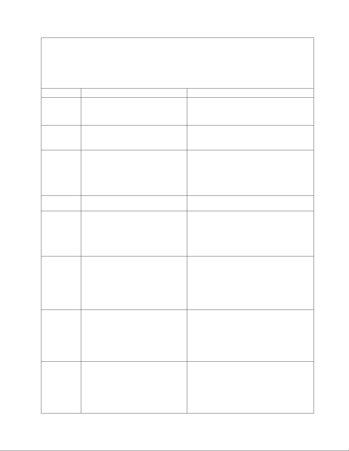
v Follow the suggested actions in the order in which they are listed in the Action column until the problem
is solved.
v See Chapter 3, “Parts listing, System x3400 Types 7973, 7974, 7975 and 7976,” on page 87 to determine
which components are customer replaceable units (CRU) and which components are field replaceable
units (FRU).
v If an action step is preceded by “(Trained service technician only),” that step must be performed only by a
trained service technician.
Error code Description Action
001-292-000 Core system: failed/CMOS checksum failed. Load the BIOS default settings by using the
Configuration/Setup Utility program, and run the test
again (see “Using the Configuration/Setup Utility
program” on page 166).
005-xxx-000 Failed video test.
1. Reseat the video adapter, if one is installed.
2. (Trained service technician only) Replace the
system board.
011-xxx-000 Failed COM1 serial port test.
1. Check the loopback plug that is connected to the
externalized serial port.
2. Check the cable from the externalized serial port
to the system board.
3. (Trained service technician only) Replace the
system board.
015-xxx-001 Failed USB test. (Trained service technician only) Replace the system
board.
015-xxx-198 Remote Supervisor Adapter II SlimLine
installed or USB device connected during
USB test.
1. If a Remote Supervisor Adapter II SlimLine is
installed as an option, remove it and run the test
again.
2. Remove all USB devices and run the test again.
3. (Trained service technician only) Replace the
system board.
020-xxx-000 Failed PCI Interface test.
1. Reseat the PCI, PCI-X, or PCI Express adapter.
2. Replace the following components one at a time,
in the order shown, restarting the server each
time:
a. Adapter
b. (Trained service technician only) System
board
030-265-001 Communication Error.
1. Update the microcode for the Serial Attached
SCSI (SAS)/SATA controller (see “Updating the
firmware” on page 165).
2. Update the BIOS code (see “Updating the
firmware” on page 165).
3. (Trained service technician only) Replace the
system board.
030-266-001 A SAS/SATA Channel Error.
1. Update the microcode for the onboard Serial
Attached SCSI (SAS)/SATA controller (see
“Updating the firmware” on page 165).
2. Update the BIOS code (see “Updating the
firmware” on page 165).
3. (Trained service technician only) Replace the
system board.
Chapter 2. Diagnostics 61
Page 80

v Follow the suggested actions in the order in which they are listed in the Action column until the problem
is solved.
v See Chapter 3, “Parts listing, System x3400 Types 7973, 7974, 7975 and 7976,” on page 87 to determine
which components are customer replaceable units (CRU) and which components are field replaceable
units (FRU).
v If an action step is preceded by “(Trained service technician only),” that step must be performed only by a
trained service technician.
Error code Description Action
030-267-001 Central Management Seq error.
1. Update the microcode for the Serial Attached
SCSI (SAS)/SATA controller (see “Updating the
firmware” on page 165).
2. Update the BIOS code (see “Updating the
firmware” on page 165).
3. (Trained service technician only) Replace the
system board.
035-002-0nn ServeRAID interface timeout.
1. Make sure that the ServeRAID controller is
configured correctly. Obtain the basic and
extended configuration status bytes and see the
ServeRAID documentation for more information.
2. Reseat the following components:
a. SAS/SATA hard disk drive backplane cable
b. ServeRAID controller
Replace the components listed in step 2 one at a
3.
time, in the order shown, restarting the server
each time.
035-230-001 Battery Low. Replace the battery module on the RAID controller.
035-231-001 Abnormal Battery Temperature. Replace the battery module on the RAID controller.
035-285-001 Adapter Communication Error.
1. Update the RAID controller firmware (see
“Updating the firmware” on page 165).
2. Reseat the RAID controller.
3. Replace the RAID controller.
035-286-001 Adapter CPU Test Error.
1. Update the RAID controller firmware (see
“Updating the firmware” on page 165).
2. Reseat the RAID controller.
3. Replace the RAID controller.
035-287-001 Adapter Local RAM Test Error.
1. Update the RAID controller firmware (see
“Updating the firmware” on page 165).
2. Reseat the RAID controller.
3. Replace the RAID controller.
035-288-001 Adapter NVSRAM Test Error.
1. Update the RAID controller firmware (see
“Updating the firmware” on page 165).
2. Reseat the RAID controller.
3. Replace the RAID controller.
035-289-001 Adapter Cache Test Error.
1. Update the RAID controller firmware (see
“Updating the firmware” on page 165).
2. Reseat the RAID controller.
3. Replace the RAID controller.
62 System x3400 Types 7973, 7974, 7975, and 7976: Problem Determination and Service Guide
Page 81

v Follow the suggested actions in the order in which they are listed in the Action column until the problem
is solved.
v See Chapter 3, “Parts listing, System x3400 Types 7973, 7974, 7975 and 7976,” on page 87 to determine
which components are customer replaceable units (CRU) and which components are field replaceable
units (FRU).
v If an action step is preceded by “(Trained service technician only),” that step must be performed only by a
trained service technician.
Error code Description Action
035-292-001 Adapter Parameter Set Error.
1. Update the RAID controller firmware (see
“Updating the firmware” on page 165).
2. Reseat the RAID controller.
3. Replace the RAID controller.
075-xxx-000 Failed power supply test. Reseat the following components:
1. Hot-swap power supply.
2. Hot-swap power backplane.
3. Replace the following components (depending on
your model):
v Hot-swap power supply
v (Trained service technician only) Non-hot-swap
power supply
089-xxx-001 Failed microprocessor test.
1. Make sure that the BIOS code is at the latest
level.
2. (Trained service technician only) Reseat
microprocessor 1.
3. Replace the following components one at a time,
in the order shown, restarting the server each
time.
a. (Trained service technician only)
Microprocessor 1
b. (Trained service technician only) System
board
089-xxx-002 Failed optional microprocessor test.
1. Make sure that the BIOS code is at the latest
level.
2. (Trained service technician only) Reseat
microprocessor 2.
3. Replace the following components one at a time,
in the order shown, restarting the server each
time.
a. (Trained service technician only)
Microprocessor 2
b. (Trained service technician only) System
board
Chapter 2. Diagnostics 63
Page 82

v Follow the suggested actions in the order in which they are listed in the Action column until the problem
is solved.
v See Chapter 3, “Parts listing, System x3400 Types 7973, 7974, 7975 and 7976,” on page 87 to determine
which components are customer replaceable units (CRU) and which components are field replaceable
units (FRU).
v If an action step is preceded by “(Trained service technician only),” that step must be performed only by a
trained service technician.
Error code Description Action
166-051-000 System Management: Failed. Unable to
communicate with ASM. It may be busy.
Run the test again.
1. Update the firmware (BIOS, service processor,
and diagnostics; see “Updating the firmware” on
page 165).
2. Run the diagnostic test again.
3. Correct other error conditions (including failed
systems-management tests and items that are
logged in the Remote Supervisor Adapter II
SlimLine system-error log) and retry.
4. Disconnect all server and option power cords
from the server, wait 30 seconds, reconnect the
power cords, and retry.
5. Reseat the Remote Supervisor Adapter II
SlimLine.
6. Replace the Remote Supervisor Adapter II
SlimLine.
166-060-000 System Management: Failed. Unable to
communicate with ASM. It may be busy.
Run the test again.
1. Update the firmware (BIOS, service processor,
and diagnostics; see “Updating the firmware” on
page 165).
2. Run the diagnostic test again.
3. Correct other error conditions (including failed
systems-management tests and items that are
logged in the Remote Supervisor Adapter II
SlimLine system-error log) and retry.
4. Disconnect all server and option power cords
from the server, wait 30 seconds, reconnect the
power cords, and retry.
5. Reseat the Remote Supervisor Adapter II
SlimLine.
6. Replace the Remote Supervisor Adapter II
SlimLine.
166-070-000 System Management: Failed. Unable to
communicate with ASM. It may be busy.
Run the test again.
1. Update the firmware (BIOS, service processor,
and diagnostics; see “Updating the firmware” on
page 165).
2. Run the diagnostic test again.
3. Correct other error conditions (including failed
systems-management tests and items that are
logged in the Remote Supervisor Adapter II
SlimLine system-error log) and retry.
4. Disconnect all server and option power cords
from the server, wait 30 seconds, reconnect the
power cords, and retry.
5. Reseat the Remote Supervisor Adapter II
SlimLine.
6. Replace the Remote Supervisor Adapter II
SlimLine.
64 System x3400 Types 7973, 7974, 7975, and 7976: Problem Determination and Service Guide
Page 83

v Follow the suggested actions in the order in which they are listed in the Action column until the problem
is solved.
v See Chapter 3, “Parts listing, System x3400 Types 7973, 7974, 7975 and 7976,” on page 87 to determine
which components are customer replaceable units (CRU) and which components are field replaceable
units (FRU).
v If an action step is preceded by “(Trained service technician only),” that step must be performed only by a
trained service technician.
Error code Description Action
166-198-000 BIOS cannot detect ASM. Reseat ASM
adapter in correct slot; ASM restart failure.
Unplug and cold boot server to reset ASM.
1. Run the diagnostic test again.
2. Correct other error conditions (including other
failed systems-management tests and items that
are logged in the Remote Supervisor Adapter II
SlimLine system-error log) and retry.
3. Disconnect all server and option power cords
from the server, wait 30 seconds, reconnect the
power cords, and retry.
4. Reseat the Remote Supervisor Adapter II
SlimLine.
5. Replace the components listed in step 4 one at a
time, in the order shown, restarting the server
each time.
166-201-000 ISMP indicates I2C errors on bus X. (Trained service technician only) Replace the system
board.
166-201-001 ISMP indicates I2C errors on bus P.
1. (Trained service technician only) Reseat the
power backplane.
2. Replace the following components one at a time,
in the order shown, restarting the server each
time:
a. (Trained service technician only) Power
backplane
b. (Trained service technician only) System
board
166-201-002 ISMP indicates I2C errors on bus I. (Trained service technician only) Replace the system
board.
166-201-003 ISMP indicates I2C errors on bus C. (Trained service technician only) Replace the system
board.
166-201-004 ISMP indicates I2C errors on bus M.
1. Reseat the DIMM.
2. Replace the following components one at a time,
in the order shown, restarting the server each
time:
a. DIMM
b. (Trained service technician only) System
board
166-201-005 ISMP indicates I2C errors on bus S.
1. Reseat the SAS/SATA hard disk drive backplane
cables.
2. Replace the following components one at a time,
in the order shown, restarting the server each
time:
a. SAS/SATA hard disk drive backplane
b. System board
Chapter 2. Diagnostics 65
Page 84

v Follow the suggested actions in the order in which they are listed in the Action column until the problem
is solved.
v See Chapter 3, “Parts listing, System x3400 Types 7973, 7974, 7975 and 7976,” on page 87 to determine
which components are customer replaceable units (CRU) and which components are field replaceable
units (FRU).
v If an action step is preceded by “(Trained service technician only),” that step must be performed only by a
trained service technician.
Error code Description Action
166-201-006 ISMP indicates I2C errors on bus O.
1. (Trained service technician only) Control-panel
assembly.
2. Replace the components one at a time, in the
order shown, restarting the server each time:
a. (Trained service technician only)
Control-panel assembly.
b. (Trained service technician only) System
board
166-201-007 ISMP indicates I2C errors on bus M0.
1. Reseat the DIMM.
2. Replace the following components one at a time,
in the order shown, restarting the server each
time:
a. DIMM
b. (Trained service technician only) System
board
166-201-008 ISMP indicates I2C errors on bus M1.
1. Reseat the DIMM.
2. Replace the following components one at a time,
in the order shown, restarting the server each
time:
a. DIMM
b. (Trained service technician only) System
board
166-260-000 ASM restart failure.
1. Disconnect all server and option power cords
from the server, wait 30 seconds, reconnect the
power cords, and retry.
2. Reseat the Remote Supervisor Adapter II
SlimLine.
3. Replace the Remote Supervisor Adapter II
SlimLine.
166-342-000 System management BIST indicates failed
tests.
1. Disconnect all server and option power cords
from the server, wait 30 seconds, reconnect the
power cords, and retry.
2. Reseat the Remote Supervisor Adapter II
SlimLine.
3. Replace the Remote Supervisor Adapter II
SlimLine.
166-400-000 ISMP Self Test Result failed tests: xxx
where xxx=flash, ROM, or RAM.
1. Disconnect all server and option power cords
from the server, wait 30 seconds, reconnect the
power cords, and retry.
2. Update the BMC firmware (see “Updating the
firmware” on page 165).
3. (Trained service technician only) Replace the
system board
66 System x3400 Types 7973, 7974, 7975, and 7976: Problem Determination and Service Guide
Page 85

v Follow the suggested actions in the order in which they are listed in the Action column until the problem
is solved.
v See Chapter 3, “Parts listing, System x3400 Types 7973, 7974, 7975 and 7976,” on page 87 to determine
which components are customer replaceable units (CRU) and which components are field replaceable
units (FRU).
v If an action step is preceded by “(Trained service technician only),” that step must be performed only by a
trained service technician.
Error code Description Action
166-400-100 DMC Self Test Result failed tests: xxx where
xxx=flash, ROM, or RAM.
1. Disconnect all server and option power cords
from the server, wait 30 seconds, reconnect the
power cords, and retry.
2. Update the BIOS code, BMC, service processor,
and diagnostics firmware (see “Updating the
firmware” on page 165).
180-197-000 SCSI ASPI driver not installed.
1. Remove the RAID adapter, if one is installed, and
run the test again.
2. Reseat the SAS/SATA hard disk drive backplane
cables.
3. Replace the following components one at a time,
in the order shown, restarting the server each
time:
a. SAS/SATA hard disk drive backplane
b. (Trained service technician only) System
board
180-361-003 Failed fan LED test.
1. Reseat the fan.
2. Replace the following components one at a time,
in the order shown, restarting the server each
time:
a. Fan
b. (Trained service technician only) System
board
180-xxx-000 Diagnostics LED failure. Run the diagnostic LED test for the failing LED.
180-xxx-001 Failed front LED panel test.
1. Reseat the control-panel assembly cable.
2. Replace the following components one at a time,
in the order shown, restarting the server each
time:
a. Control-panel assembly cable
b. (Trained service technician only) System
board
180-xx-002 Failed diagnostics LED panel test.
1. Reseat the control-panel assembly cable.
2. Replace the following components one at a time,
in the order shown, restarting the server each
time:
a. Control-panel assembly cable
b. (Trained service technician only) System
board
Chapter 2. Diagnostics 67
Page 86

v Follow the suggested actions in the order in which they are listed in the Action column until the problem
is solved.
v See Chapter 3, “Parts listing, System x3400 Types 7973, 7974, 7975 and 7976,” on page 87 to determine
which components are customer replaceable units (CRU) and which components are field replaceable
units (FRU).
v If an action step is preceded by “(Trained service technician only),” that step must be performed only by a
trained service technician.
Error code Description Action
180-xxx-005 Failed SCSI backplane LED test.
1. Reseat the following components:
a. SAS/SATA hard disk drive
b. SAS/SATA hard disk drive backplane cable
c. RAID adapter
Replace the following components one at a time,
2.
in the order shown, restarting the server each
time:
a. SAS/SATA hard disk drive backplane
b. SAS/SATA hard disk drive backplane cable
c. RAID adapter
d. (Trained service technician only) System
board
180-xxx-006 Failed memory LED test.
1. Reseat the DIMM.
2. Replace the following components one at a time,
in the order shown, restarting the server each
time:
a. DIMM
b. (Trained service technician only) System
board
180-xxx-007 Failed power supply fan LED test.
1. Reseat the power supply.
2. Replace the following components one at a time,
in the order shown, restarting the server each
time:
a. Power supply
b. (Trained service technician only) System
board
180-xxx-008 Failed I/O board LED test. (Trained service technician only) Replace the system
board.
180-xxx-009 Failed Active™ PCI LED test. (Trained service technician only) Replace the system
board.
201-198-000 Memory Test Aborted: Could not run the
test; suspect system board error.
1. Restart the server.
2. Run the diagnostic test again.
3. Reinstall the diagnostic programs (see “Updating
the firmware” on page 165).
4. (Trained service technician only) Replace the
system board.
201-198-00n Memory Test Aborted: Could not run the
test.
Note: n = 1-9 (programming error).
1. Restart the server.
2. Run the diagnostic test again.
3. Reinstall the diagnostic programs (see “Updating
the firmware” on page 165).
68 System x3400 Types 7973, 7974, 7975, and 7976: Problem Determination and Service Guide
Page 87

v Follow the suggested actions in the order in which they are listed in the Action column until the problem
is solved.
v See Chapter 3, “Parts listing, System x3400 Types 7973, 7974, 7975 and 7976,” on page 87 to determine
which components are customer replaceable units (CRU) and which components are field replaceable
units (FRU).
v If an action step is preceded by “(Trained service technician only),” that step must be performed only by a
trained service technician.
Error code Description Action
201-xxx-n99 Failed memory test.
Note: n = 1-4 (DIMM pair)
99 = Both DIMMs in the pair failed
1. Reseat the DIMMs.
2. Replace the following components one at a time,
in the order shown, restarting the server each
time:
a. DIMM pair
b. (Trained service technician only) System
board
202-xxx-00n Failed system cache test.
1. (Trained service technician only) Reseat
microprocessor n.
2. Replace the following components one at a time,
in the order shown, restarting the server each
time:
a. (Trained service technician only)
Microprocessor n
b. (Trained service technician only) System
board
215-xxx-000 Failed CD or DVD test.
1. Run the test again with a different CD or DVD.
2. Reseat the CD or DVD drive cable.
3. Replace the following components one at a time,
in the order shown, restarting the server each
time:
a. CD or DVD drive
b. (Trained service technician only) System
board
217-xxx-000 Failed fixed disk test.
Note: If RAID is configured, the fixed disk
number refers to the RAID logical array.
217-xxx-001 Failed fixed disk test.
Note: If RAID is configured, the fixed disk
number refers to the RAID logical array.
217-xxx-002 Failed fixed disk test.
Note: If RAID is configured, the fixed disk
number refers to the RAID logical array.
217-xxx-003 Failed fixed disk test.
Note: If RAID is configured, the fixed disk
number refers to the RAID logical array.
1. Reseat hard disk drive 1.
2. Replace hard disk drive 1.
1. Reseat hard disk drive 2.
2. Replace hard disk drive 2.
1. Reseat hard disk drive 3.
2. Replace hard disk drive 3.
1. Reseat hard disk drive 4.
2. Replace hard disk drive 4.
Chapter 2. Diagnostics 69
Page 88

v Follow the suggested actions in the order in which they are listed in the Action column until the problem
is solved.
v See Chapter 3, “Parts listing, System x3400 Types 7973, 7974, 7975 and 7976,” on page 87 to determine
which components are customer replaceable units (CRU) and which components are field replaceable
units (FRU).
v If an action step is preceded by “(Trained service technician only),” that step must be performed only by a
trained service technician.
Error code Description Action
217-198-xxx Could not establish drive parameters.
1. Reseat the following components, depending on
the server model:
v Hot-swap models:
a. Hard disk drive
b. Hard disk drive cable
c. SAS/SATA controller cable
d. SAS/SATA controller
Simple-swap models:
v
a. Hard disk drive
b. Hard disk drive cable
Replace the following components one at a time,
2.
depending on the server model, in the order
shown, restarting the server each time:
v Hot-swap models:
a. Hard disk drive
b. SAS/SATA controller cable
c. SAS/SATA backplane
d. SAS/SATA controller
Simple-swap and non-hot-swap models:
v
a. Hard disk drive
b. Hard disk drive cable
(Trained service technician only) Replace the
3.
system board.
301-xxx-000 Failed keyboard test.
Note: After installing a USB keyboard, you
might have to use the Configuration/Setup
Utility program to enable keyboardless
operation and prevent the POST error
message 301 from being displayed during
startup.
1. Reseat the keyboard cable.
2. Replace the following components one at a time,
in the order shown, restarting the server each
time:
a. Keyboard
b. (Trained service technician only) System
board
302-xxx-xxx Failed mouse test.
1. Reseat the mouse cable.
2. Replace the following components one at a time,
in the order shown, restarting the server each
time:
a. Mouse
b. (Trained service technician only) System
board
70 System x3400 Types 7973, 7974, 7975, and 7976: Problem Determination and Service Guide
Page 89

v Follow the suggested actions in the order in which they are listed in the Action column until the problem
is solved.
v See Chapter 3, “Parts listing, System x3400 Types 7973, 7974, 7975 and 7976,” on page 87 to determine
which components are customer replaceable units (CRU) and which components are field replaceable
units (FRU).
v If an action step is preceded by “(Trained service technician only),” that step must be performed only by a
trained service technician.
Error code Description Action
305-xxx-xxx Failed video monitor test.
1. Reseat the monitor cable.
2. Replace the following components one at a time,
in the order shown, restarting the server each
time:
a. Monitor
b. (Trained service technician only) System
board
405-xxx-000 Failed Ethernet test on controller on the
system board.
1. Run the Configuration/Setup Utility program.
Make sure that:
v The Ethernet adapter is not disabled.
v The BIOS code is at the latest level.
Run the loopback diagnostic.
2.
3. (Trained service technician only) Replace the
system board.
Chapter 2. Diagnostics 71
Page 90

Recovering from a BIOS update failure
If power to the server is interrupted while BIOS code is being updated, the server
might not restart correctly or might not display video. If this happens, complete the
following steps to recover:
1. Read the safety information that begins on page vii and “Handling
static-sensitive devices” on page 97.
2. Turn off the server and all attached devices; then, disconnect all power cords
and external cables.
3. Unlock and remove the side cover (see “Removing the side cover” on page
100).
4. Locate the boot block recovery switch 1 on the system board, and remove any
adapters that impede access to the switches (see “Removing an adapter” on
page 102).
DIMM LEDs
6
12
5
11
4
10
3
9
8
2
7
1
5. Toggle the boot block recovery switch to On.
6. Replace any adapters that you removed (see “Installing an adapter” on page
Boot block/Clear CMOS
103); then, install the side cover (see “Installing the side cover” on page 101).
7. Reconnect all external cables and power cords.
8. Insert the update CD into the CD or DVD drive.
9. Turn on the server and the monitor.
After the update session is completed, remove the CD from the drive and turn
off the server.
10. Disconnect all power cords and external cables.
11. Remove the side cover (see “Removing the side cover” on page 100).
12. Remove any adapters that impede access to the boot block recovery switch
(see “Removing an adapter” on page 102).
72 System x3400 Types 7973, 7974, 7975, and 7976: Problem Determination and Service Guide
Page 91

13. Toggle the boot block recovery switch to 1.
14. Replace any adapters that you removed (see “Installing an adapter” on page
103); then, install the side cover (see “Installing the side cover” on page 101).
15. Lock the side cover if it was unlocked during removal.
16. Reconnect the external cables and power cords; then, turn on the attached
devices and turn on the server.
The following table describes the function of each switch on the system board.
Table 4. System board switches
Switch number Description
1 Boot block:
v When this switch is on 1, this is normal mode.
v When this switch is toggled to On, this enables the
system to recover if the BIOS code becomes damaged.
2 Clear CMOS:
v When this switch is on 2, this is normal mode. This
keeps the CMOS data.
v When this switch is toggled to On, this clears the CMOS
data, which clears the power-on password and
administrator password.
Chapter 2. Diagnostics 73
Page 92

System-error log messages
A system-error log is generated only if a Remote Supervisor Adapter II SlimLine is
installed. The system-error log can contain messages of three types:
Information Information messages do not require action; they record significant
system-level events, such as when the server is started.
Warning Warning messages do not require immediate action; they indicate
possible problems, such as when the recommended maximum
ambient temperature is exceeded.
Error Error messages might require action; they indicate system errors,
such as when a fan is not detected.
Each message contains date and time information, and it indicates the source of
the message (POST/BIOS or the service processor).
Note: The BMC log, which you can view through the Configuration/Setup Utility
program, also contains many information, warning, and error messages.
In the following example, the system-error log message indicates that the server
was turned on at the recorded time.
- - - - - - - - - - - - - - - - - - - - - - - - - - - - - - Date/Time: 2002/05/07 15:52:03
DMI Type:
Source: SERVPROC
Error Code: System Complex Powered Up
Error Code:
Error Data:
Error Data:
- - - - - - - - - - - - - - - - - - - - - - - - - - - - - - - - - - - - - - -
The following table describes the possible system-error log messages and
suggested actions to correct the detected problems.
v Follow the suggested actions in the order in which they are listed in the Action column until the problem
is solved.
v See Chapter 3, “Parts listing, System x3400 Types 7973, 7974, 7975 and 7976,” on page 87 to determine
which components are customer replaceable units (CRU) and which components are field replaceable
units (FRU).
v If an action step is preceded by “(Trained service technician only),” that step must be performed only by a
trained service technician.
System-error log message Action
A system NMI was detected Make sure that the system software is operating correctly and does
not conflict with other software; the system software has created a
software NMI, or pressing the NMI button has created a service
NMI.
Alert accepted by remote system x; type:y, ID:z Information only.
Alert accepted from system x; type:y, sender’s
ID:z
Alert ID x will be retried by sender; when
accepted by a remote system, it will have a
different ID
Alert not accepted by remote system x; type:y,
ID:z
Information only.
Information only.
Information only.
74 System x3400 Types 7973, 7974, 7975, and 7976: Problem Determination and Service Guide
Page 93
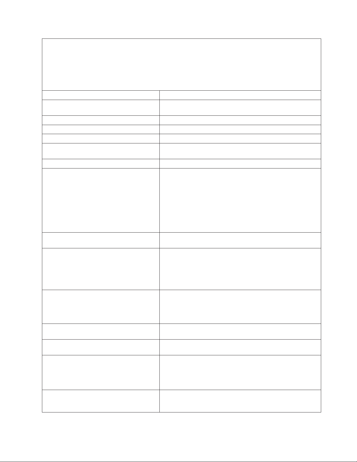
v Follow the suggested actions in the order in which they are listed in the Action column until the problem
is solved.
v See Chapter 3, “Parts listing, System x3400 Types 7973, 7974, 7975 and 7976,” on page 87 to determine
which components are customer replaceable units (CRU) and which components are field replaceable
units (FRU).
v If an action step is preceded by “(Trained service technician only),” that step must be performed only by a
trained service technician.
System-error log message Action
Alert not accepted from system x; type:y,
Information only.
sender’s ID:z
ASM Reset -- reason unknown Information only.
ASM Reset due to x, Instruction Fault: y Information only.
ASM Reset due Watchdog timeout Information only.
ASM Reset was caused by restoring default
Information only.
values
ASM Reset was initiated by the user Information only.
Cable: Service processor not present
1. Check the pins and connectors on the cable that connects the
Remote Supervisor Adapter II SlimLine or other service
processor adapter to the Remote Supervisor Adapter SlimLine
connector on the system board (see “System-board option
connectors” on page 13 for the location of the connector).
2. Reseat the cable (both ends) from the Remote Supervisor
Adapter II SlimLine or other service processor adapter to the
Remote Supervisor Adapter SlimLine connector on the system
board.
Configuration error recovery on the Inter-connect
Information only.
network
CPU x over temperature
1. Make sure that the heat sink has good airflow and is not
obstructed.
2. Reseat the following components:
a. Heat sink cable
b. (Trained service technician only) Heat sink
DASD controller removal
1. Make sure that the onboard SAS/SATA controller cable is not
damaged.
2. Reseat the onboard SAS/SATA controller cable.
3. Replace the onboard SAS/SATA controller cable.
DHCP failure,no IP@ assigned-
Information only.
RETRYING!,rc=xxx,count=yyy
Dialback failed for userid w. Could not connect
Information only.
at phone number x, y, z
ENET[eee] DHCP-
Information only.
HstNme=a,DN=b,IP@=ccc.ccc.ccc.ccc
GW@=ddd.ddd.ddd.ddd, NMsk=fff.fff.fff.fff,
DNS1@=ggg.ggg.ggg.ggg,
DNS2@=hhh.hhh.hhh.hhh
ENET[eee] IP-Cfg:HstName=x,
Information only.
IP@=ccc.ccc.ccc.ccc, GW@=ddd.ddd.ddd.ddd,
NetMsk=fff.fff.fff.fff
Chapter 2. Diagnostics 75
Page 94

v Follow the suggested actions in the order in which they are listed in the Action column until the problem
is solved.
v See Chapter 3, “Parts listing, System x3400 Types 7973, 7974, 7975 and 7976,” on page 87 to determine
which components are customer replaceable units (CRU) and which components are field replaceable
units (FRU).
v If an action step is preceded by “(Trained service technician only),” that step must be performed only by a
trained service technician.
System-error log message Action
Failure reading an I2C device, possible bus
failure
1. Reseat the following components:
a. AC power cords
b. Hot-swap power supplies (if any are installed)
c. (Trained service technician only) Power-supply cables on
the system board
(Trained service technician only) Replace the system board.
2.
Fan x Failure
1. Make sure that fan x is not obstructed.
2. Reseat the fan x cable.
3. Replace fan x.
Fan x Outside Recommended Speed
1. Make sure that fan x is not obstructed.
2. Reseat the fan x cable.
3. Replace fan x.
Flash of x by y via z was successful...w Information only.
Flash of x via z failed for user z...z Information only.
Flash succeeded for x (address: y) Information only.
Hard Drive x Fault
1. Run the diagnostics programs.
2. Replace hard disk drive x.
3. Replace the following component, depending on the server
model:
v Hot-swap models: SAS/SATA backplane
v Simple-swap: Hard disk drive x cable
Hard drive x removal detected. Reseat hard disk drive x.
Internal Error CPU Fault Information only. If the message remains:
1. (Trained service technician only) Reseat the microprocessor.
2. (Trained service technician only) Replace the microprocessor.
Invalid userid or password received. Userid is w,
Information only.
x, y, z
LAN: Command Mode tamper triggered.
Information only.
Possible break in attempt
LAN: Telnet tamper triggered. Possible break in
Information only.
attempt
LAN: Web Server tamper delay triggered.
Information only.
Possible break-in attempt
LAN: Ethernet interface is no longer active Information only.
LAN: Ethernet interface is now active Information only.
No ISMP Gateway defined for the interconnect
Information only.
network. RSA x is Assuming the Gateway
OS Watchdog response disabled by x Information only.
76 System x3400 Types 7973, 7974, 7975, and 7976: Problem Determination and Service Guide
Page 95

v Follow the suggested actions in the order in which they are listed in the Action column until the problem
is solved.
v See Chapter 3, “Parts listing, System x3400 Types 7973, 7974, 7975 and 7976,” on page 87 to determine
which components are customer replaceable units (CRU) and which components are field replaceable
units (FRU).
v If an action step is preceded by “(Trained service technician only),” that step must be performed only by a
trained service technician.
System-error log message Action
OS Watchdog response enabled by x Information only.
PFA Alert, see preceding error in system error
Information only. See the preceding entry in the system-error log.
log
Possible ASM reset occurred -- reason unknown Information only.
Power off Information only.
Power on Information only.
PPP[xxx] PPP-Cfg, Local-
Information only.
IP@=aaa.aaa.aaa.aaa, RemoteIP@=bbb.bbb.bbb.bbb NetMsk=ccc.ccc.ccc.ccc,
Auth=ddd
PPP_1:Client Connected at xxx bps Information only.
PPP_1:User requested to abort PPP interface Information only.
Received alert from system x; type:y, sender’s
Information only.
ID:z
Remote access attempt failed Information only.
Remote access attempt failed. Invalid userid or
Information only.
password received. Userid is ’x’ from WEB
browser at IP@=yyy.yyy.yyy.yyy
Remote access attempt failed. Invalid userid or
Information only.
password received. Userid is ’x’ from CMD
mode client at IP@=yyy.yyy.yyy.yyy
Remote access attempt failed. Invalid userid or
Information only.
password received. Userid is ’x’ from TELNET
client at IP@=yyy.yyy.yyy.yyy
Remote Login Successful. Login ID: Information only.
Remote Login Successful. Login ID:’x’ from
Information only.
CMD mode client at IP@=yyy.yyy.yyy.yyy
Retried alert accepted from system x; type:y,
Information only.
sender’s ID:z
Retry count exceeded. Incorrect password
Information only.
entered too many times for userid w, x, y, z
RS485 broadcast from x ignored; more than y
Information only.
devices present on the RS485 network
RS485 connection to system x has ended Information only.
RS485 network overload has cleared; x or fewer
Information only.
devices are present on the RS485 network
RSA x Became the ISMP Gateway Information only.
Running the backup ASM main application Information only.
Secondary Device Event[00 x UNKNOWN-y] Information only.
Sending alert to remote system x; type:y, ID:z Information only.
Chapter 2. Diagnostics 77
Page 96

v Follow the suggested actions in the order in which they are listed in the Action column until the problem
is solved.
v See Chapter 3, “Parts listing, System x3400 Types 7973, 7974, 7975 and 7976,” on page 87 to determine
which components are customer replaceable units (CRU) and which components are field replaceable
units (FRU).
v If an action step is preceded by “(Trained service technician only),” that step must be performed only by a
trained service technician.
System-error log message Action
Serial tamper delay triggered. Possible serial
Information only.
port break-in attempt
System board is over recommended
temperature
1. Make sure that the fans have good airflow and are not
obstructed.
2. (Trained service technician only) Replace the system board.
System board is under recommended
temperature
1. Make sure that the fans have good airflow and are not
obstructed.
2. (Trained service technician only) Replace the system board.
System Complex Powered Down Information only.
System error log full Clear the current logs.
System is over recommended voltage for +3.3V
1. Reseat the following components:
a. Hot-swap power supplies (if any are installed)
b. (Trained service technician only) Power-supply cables on
the system board
(Trained service technician only) Replace the system board.
2.
System is over recommended voltage for 1.5V
CPU
1. Reseat the following components:
a. Hot-swap power supplies (if any are installed)
b. (Trained service technician only) Power-supply cables on
the system board
(Trained service technician only) Replace the system board.
2.
System is over recommended voltage on the
(Trained service technician only) Reseat the microprocessor.
VRM
System is under recommended voltage for
+3.3V
1. Reseat the following components:
a. Hot-swap power supplies (if any are installed)
b. (Trained service technician only) Power-supply cables on
the system board
(Trained service technician only) Replace the system board.
2.
System is under recommended voltage for 1.5V
CPU
1. Reseat the following components:
a. Hot-swap power supplies (if any are installed)
b. (Trained service technician only) Power-supply cables on
the system board
(Trained service technician only) Replace the system board.
2.
System is under recommended voltage on the
(Trained service technician only) Reseat the microprocessor.
VRM
System log 75% full Clear the current logs.
System log cleared Information only.
System Memory Error
1. Reseat the DIMMs.
2. Replace the DIMMs.
78 System x3400 Types 7973, 7974, 7975, and 7976: Problem Determination and Service Guide
Page 97

v Follow the suggested actions in the order in which they are listed in the Action column until the problem
is solved.
v See Chapter 3, “Parts listing, System x3400 Types 7973, 7974, 7975 and 7976,” on page 87 to determine
which components are customer replaceable units (CRU) and which components are field replaceable
units (FRU).
v If an action step is preceded by “(Trained service technician only),” that step must be performed only by a
trained service technician.
System-error log message Action
System over recommended voltage for +12v
1. Reseat the following components:
a. Hot-swap power supplies (if any are installed)
b. (Trained service technician only) Power-supply cables on
the system board
(Trained service technician only) Replace the system board.
2.
System over recommended voltage on +2.5v
1. Reseat the following components:
a. Hot-swap power supplies (if any are installed)
b. (Trained service technician only) Power-supply cables on
the system board
(Trained service technician only) Replace the system board.
2.
System over recommended voltage on
continuous +5v
1. Reseat the following components:
a. Hot-swap power supplies (if any are installed)
b. (Trained service technician only) Power-supply cables on
the system board
(Trained service technician only) Replace the system board.
2.
System shut off due to system board under
temperature
1. Make sure that the fans have good airflow and are not
obstructed.
2. (Trained service technician only) Replace the system board.
System shutoff due to +12v over voltage
1. Reseat the following components:
a. Hot-swap power supplies (if any are installed)
b. (Trained service technician only) Power-supply cables on
the system board
(Trained service technician only) Replace the system board.
2.
System shutoff due to +12v under voltage
1. Reseat the following components:
a. Hot-swap power supplies (if any are installed)
b. (Trained service technician only) Power-supply cables on
the system board
(Trained service technician only) Replace the system board.
2.
System shutoff due to +2.5v over voltage
1. Reseat the following components:
a. Hot-swap power supplies (if any are installed)
b. (Trained service technician only) Power-supply cables on
the system board
(Trained service technician only) Replace the system board.
2.
System shutoff due to +2.5v under voltage
1. Reseat the following components:
a. Hot-swap power supplies (if any are installed)
b. (Trained service technician only) Power-supply cables on
the system board
(Trained service technician only) Replace the system board.
2.
Chapter 2. Diagnostics 79
Page 98

v Follow the suggested actions in the order in which they are listed in the Action column until the problem
is solved.
v See Chapter 3, “Parts listing, System x3400 Types 7973, 7974, 7975 and 7976,” on page 87 to determine
which components are customer replaceable units (CRU) and which components are field replaceable
units (FRU).
v If an action step is preceded by “(Trained service technician only),” that step must be performed only by a
trained service technician.
System-error log message Action
System shutoff due to +3.3V over voltage
1. Reseat the following components:
a. Hot-swap power supplies (if any are installed)
b. (Trained service technician only) Power-supply cables on
the system board
(Trained service technician only) Replace the system board.
2.
System shutoff due to +3.3V under voltage
1. Reseat the following components:
a. Hot-swap power supplies (if any are installed)
b. (Trained service technician only) Power-supply cables on
the system board
(Trained service technician only) Replace the system board.
2.
System shutoff due to 1.5V CPU over voltage
1. Reseat the following components:
a. Hot-swap power supplies (if any are installed)
b. (Trained service technician only) Power-supply cables on
the system board
(Trained service technician only) Replace the system board.
2.
System shutoff due to 1.5V CPU under voltage
1. Reseat the following components:
a. Hot-swap power supplies (if any are installed)
b. (Trained service technician only) Power-supply cables on
the system board
(Trained service technician only) Replace the system board.
2.
System shutoff due to board over temperature
1. Make sure that all fans have good airflow and are not
obstructed.
2. (Trained service technician only) Replace the system board.
System shutoff due to continuous +5v over
voltage
1. Reseat the following components:
a. Hot-swap power supplies (if any are installed)
b. (Trained service technician only) Power-supply cables on
the system board
(Trained service technician only) Replace the system board.
2.
System shutoff due to continuous +5v under
voltage
1. Reseat the following components:
a. Hot-swap power supplies (if any are installed)
b. (Trained service technician only) Power-supply cables on
the system board
(Trained service technician only) Replace the system board.
2.
System shutoff due to CPU over temperature
1. Make sure that the heat sink has good airflow and is not
obstructed.
2. Reseat the following components:
a. Heat sink cable
b. (Trained service technician only) Heat sink
80 System x3400 Types 7973, 7974, 7975, and 7976: Problem Determination and Service Guide
Page 99

v Follow the suggested actions in the order in which they are listed in the Action column until the problem
is solved.
v See Chapter 3, “Parts listing, System x3400 Types 7973, 7974, 7975 and 7976,” on page 87 to determine
which components are customer replaceable units (CRU) and which components are field replaceable
units (FRU).
v If an action step is preceded by “(Trained service technician only),” that step must be performed only by a
trained service technician.
System-error log message Action
System shutoff due to VRM over voltage
1. (Trained service technician only) Reseat the microprocessor.
2. Replace the following components one at a time, in the order
shown, restarting the server each time:
a. (Trained service technician only) Microprocessor
b. (Trained service technician only) System board
System shutoff due to VRM under voltage
1. (Trained service technician only) Reseat the microprocessor.
2. Replace the following components one at a time, in the order
shown, restarting the server each time:
a. (Trained service technician only) Microprocessor
b. (Trained service technician only) System board
System under recommended voltage for +12v
1. Reseat the following components:
a. Hot-swap power supplies (if any are installed)
b. (Trained service technician only) Power-supply cables on
the system board
(Trained service technician only) Replace the system board.
2.
System under recommended voltage on +2.5v
1. Reseat the following components:
a. Hot-swap power supplies (if any are installed)
b. (Trained service technician only) Power-supply cables on
the system board
(Trained service technician only) Replace the system board.
2.
System under recommended voltage on
continuous +5v
1. Reseat the following components:
a. Hot-swap power supplies (if any are installed)
b. (Trained service technician only) Power-supply cables on
the system board
(Trained service technician only) Replace the system board.
2.
System x started a RS485 connection with us Information only.
We started a RS485 connection with remote
Information only.
system x
We will retry sending alert ID x; when accepted
Information only.
by a remote system, it will have a different ID
Windows blue screen has been captured Information only.
Chapter 2. Diagnostics 81
Page 100

Solving SCSI problems
Note: This information also applies to Serial Attached SCSI (SAS) problems.
For any SCSI error message, one or more of the following devices might be
causing the problem:
v A failing SCSI device (adapter, drive, or controller)
v An incorrect SCSI termination jumper setting
v A missing or incorrectly installed SCSI terminator
v A defective SCSI terminator
v An incorrectly installed cable
v A defective cable
any SCSI error message, follow these suggested actions in the order in which
For
they are listed until the problem is solved:
1. Make sure that external SCSI devices are turned on before you turn on the
server.
2. Make sure that the cables for all external SCSI devices are connected correctly.
3. If an external SCSI device is attached, make sure that the external SCSI
termination is set to automatic.
4. Make sure that the last device in each SCSI chain is terminated correctly.
5. Make sure that the SCSI devices are configured correctly.
Solving power problems
Power problems can be difficult to solve. For example, a short circuit can exist
anywhere on any of the power distribution buses. Usually, a short circuit will cause
the power subsystem to shut down because of an overcurrent condition. To
diagnose a power problem, use the following general procedure:
1. Turn off the server and disconnect all ac power cords.
2. Check for loose cables in the power subsystem. Also check for short circuits, for
example, if a loose screw is causing a short circuit on a circuit board.
3. Remove the adapters and disconnect the cables and power cords to all internal
and external devices until the server is at the minimum configuration that is
required for the server to start (see “Solving undetermined problems” on page
84 for the minimum configuration).
4. Reconnect all ac power cords and turn on the server. If the server starts
successfully, replace the adapters and devices one at a time until the problem is
isolated.
If the server does not start from the minimum configuration, replace the components
in the minimum configuration one at a time until the problem is isolated.
82 System x3400 Types 7973, 7974, 7975, and 7976: Problem Determination and Service Guide
 Loading...