

Page 1
System x3105
Type 4347
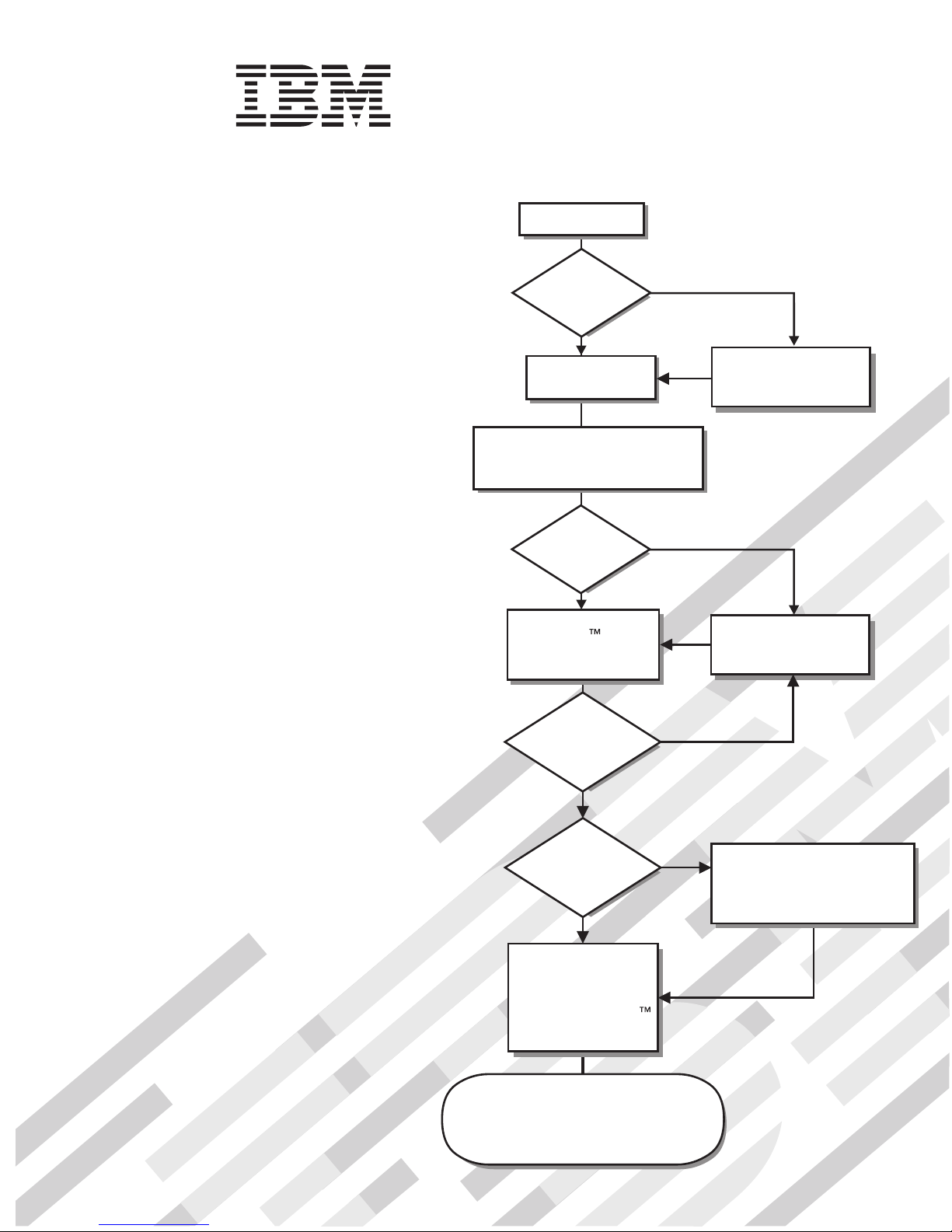
Start the server.
Installation Guide
Welcome.
Thank you for buying an
IBM server.
is based on the X-Architecture
technology, and it features
superior performance, availability,
and affordability.
This server
contains information for setting
up and configuring your server.
For detailed information about
your server, view the publications
on the
Your server
Installation Guide
Documentation CD.
Did the server
start correctly?
Ye s
Turn off the server
and install options.
Cable the server and options;
then, restart the server.
Did the server
start correctly?
Ye s
Use the IBM
ServerGuide program
to set up and
configure hardware.
Was the
server setup
completed?
No
No
No
Go to the Server Support
flow chart on the reverse
side of this page.
Go to the Server Support
flow chart on the reverse
side of this page.
You can also find the most
current information about
your server at:
http://www.ibm.com/servers
/eserver/support/xseries/index.html/.
Ye s
Use
ServerGuide to
install the operating
system?
Ye s
Install applications,
such as IBM systems
management software
and IBM ServeRAID
programs
The server is ready to use.
Go to
http://www.ibm.com/support/mysupport/
to register the server.
No
Go to the Web for instructions:
http://www.ibm.com/servers/
eserver/support/xseries/
index.html.
Page 2
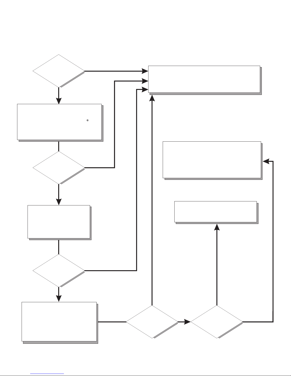
Server Support
Is the server working
correctly?
Ye s
No
Check all cables for loose connections
and verify that all optional devices you
installed are on the ServerProven list at
http://www.ibm.com/servers/eserver/
serverproven/compat/us/.
Is the problem
solved?
Ye s
No
Register the server. Go to
http://www.ibm.com/support/mysupport/.
View information about IBM Support Line at
http://www.ibm.com/services/sl/products/
or view support telephone numbers at
http://www.ibm.com/planetwide/.
See the troubleshooting
information that comes with
the server to determine
the cause of the problem
and the action to take.
Is the problem
solved?
Ye s
No
Update the firmware to the
latest level.
You can download firmware from
http://www.ibm.com/servers/
eserver/support/xseries/
index.html
Ye s
Is the problem
solved?
View support telephone numbers at
http://www.ibm.com/planetwide/.
Hardware
No Software
Hardware or
software problem?
Page 3

System x3105 Type 4347
Installation Guide
Page 4

Note:
Before using this information and the product it supports, read the general information in Appendix B,
“Notices,” on page 67 and the Warranty and Support Information document on the IBM System x
Documentation CD.
Second Edition (March 2007)
© Copyright International Business Machines Corporation 2007. All rights reserved.
US Government Users Restricted Rights – Use, duplication or disclosure restricted by GSA ADP Schedule Contract
with IBM Corp.
Page 5

Contents
Safety . . . . . . . . . . . . . . . . . . . . . . . . . . . .v
Chapter 1. Introduction . . . . . . . . . . . . . . . . . . . . . .1
The IBM System x Documentation CD . . . . . . . . . . . . . . . . .3
Hardware and software requirements . . . . . . . . . . . . . . . .3
Using the Documentation Browser . . . . . . . . . . . . . . . . .3
Notices and statements in this document . . . . . . . . . . . . . . . .4
Features and specifications . . . . . . . . . . . . . . . . . . . . .5
Major components of the server . . . . . . . . . . . . . . . . . . .6
Chapter 2. Installing optional devices . . . . . . . . . . . . . . . .7
Installation guidelines . . . . . . . . . . . . . . . . . . . . . . .7
System reliability guidelines . . . . . . . . . . . . . . . . . . . .8
Handling static-sensitive devices . . . . . . . . . . . . . . . . . .8
Removing the side cover . . . . . . . . . . . . . . . . . . . . . .9
Removing the bezel . . . . . . . . . . . . . . . . . . . . . . .10
Installing a memory module . . . . . . . . . . . . . . . . . . . .11
Installing a drive . . . . . . . . . . . . . . . . . . . . . . . .14
Installing a CD or DVD drive . . . . . . . . . . . . . . . . . . .15
Installing an optional tape drive . . . . . . . . . . . . . . . . . .18
Installing a SATA hard disk drive . . . . . . . . . . . . . . . . .19
Power and signal cables for internal drives . . . . . . . . . . . . .22
Installing an adapter . . . . . . . . . . . . . . . . . . . . . . .23
Cabling an optional SCSI adapter . . . . . . . . . . . . . . . . . .25
Completing the installation . . . . . . . . . . . . . . . . . . . . .25
Installing the bezel . . . . . . . . . . . . . . . . . . . . . .25
Installing the side cover . . . . . . . . . . . . . . . . . . . . .26
Connecting the cables . . . . . . . . . . . . . . . . . . . . .27
Updating the server configuration . . . . . . . . . . . . . . . . .28
Chapter 3. Server controls, LEDs, and power . . . . . . . . . . . . .29
Front view . . . . . . . . . . . . . . . . . . . . . . . . . .29
Rear view . . . . . . . . . . . . . . . . . . . . . . . . . . .31
Server power features . . . . . . . . . . . . . . . . . . . . . .32
Setting the power supply voltage . . . . . . . . . . . . . . . . .32
Turning on the server . . . . . . . . . . . . . . . . . . . . .32
Turning off the server . . . . . . . . . . . . . . . . . . . . .33
Chapter 4. Configuring the server . . . . . . . . . . . . . . . . .35
Using the ServerGuide Setup and Installation CD . . . . . . . . . . . .35
Using the Configuration/Setup Utility program . . . . . . . . . . . . .35
Using the Boot Menu program . . . . . . . . . . . . . . . . . . .36
Enabling the Broadcom NetXtreme Gigabit Ethernet Boot Agent . . . . . . .36
Configuring the Broadcom NetXtreme Gigabit Ethernet controller . . . . . .36
Chapter 5. Solving problems . . . . . . . . . . . . . . . . . . .39
Diagnostic tools overview . . . . . . . . . . . . . . . . . . . . .39
POST beep codes . . . . . . . . . . . . . . . . . . . . . . .40
POST error codes . . . . . . . . . . . . . . . . . . . . . . . .40
Troubleshooting tables . . . . . . . . . . . . . . . . . . . . . .50
CD or DVD drive problems . . . . . . . . . . . . . . . . . . .50
Diskette drive problems . . . . . . . . . . . . . . . . . . . . .51
General problems . . . . . . . . . . . . . . . . . . . . . . .51
© Copyright IBM Corp. 2007 iii
Page 6

Hard disk drive problems . . . . . . . . . . . . . . . . . . . .52
Intermittent problems . . . . . . . . . . . . . . . . . . . . . .52
Keyboard, mouse, or pointing-device problems . . . . . . . . . . . .53
Memory problems . . . . . . . . . . . . . . . . . . . . . . .54
Microprocessor problems . . . . . . . . . . . . . . . . . . . .54
Monitor or video problems . . . . . . . . . . . . . . . . . . . .55
Optional-device problems . . . . . . . . . . . . . . . . . . . .57
Power problems . . . . . . . . . . . . . . . . . . . . . . .58
Serial port problems . . . . . . . . . . . . . . . . . . . . . .59
ServerGuide problems . . . . . . . . . . . . . . . . . . . . .59
Software problems . . . . . . . . . . . . . . . . . . . . . .60
Universal Serial Bus (USB) port problems . . . . . . . . . . . . . .61
System-board error LEDs . . . . . . . . . . . . . . . . . . . . .61
Recovering from a BIOS update failure . . . . . . . . . . . . . . . .62
Appendix A. Getting help and technical assistance . . . . . . . . . .65
Before you call . . . . . . . . . . . . . . . . . . . . . . . . .65
Using the documentation . . . . . . . . . . . . . . . . . . . . .65
Getting help and information from the World Wide Web . . . . . . . . . .66
Software service and support . . . . . . . . . . . . . . . . . . .66
Hardware service and support . . . . . . . . . . . . . . . . . . .66
IBM Taiwan product service . . . . . . . . . . . . . . . . . . . .66
Appendix B. Notices . . . . . . . . . . . . . . . . . . . . . .67
Trademarks . . . . . . . . . . . . . . . . . . . . . . . . . .67
Important notes . . . . . . . . . . . . . . . . . . . . . . . . .68
Product recycling and disposal . . . . . . . . . . . . . . . . . . .69
Battery return program . . . . . . . . . . . . . . . . . . . . . .71
Electronic emission notices . . . . . . . . . . . . . . . . . . . .71
Federal Communications Commission (FCC) statement . . . . . . . . .71
Industry Canada Class B emission compliance statement . . . . . . . .72
Avis de conformité à la réglementation d’Industrie Canada . . . . . . . .72
European Union EMC Directive conformance statement . . . . . . . . .72
Japanese Voluntary Control Council for Interference (VCCI) statement . . .73
Index . . . . . . . . . . . . . . . . . . . . . . . . . . . .75
iv System x3105 Type 4347: Installation Guide
Page 7
Safety
Before installing this product, read the Safety Information.
Antes de instalar este produto, leia as Informações de Segurança.
Pred instalací tohoto produktu si prectete prírucku bezpecnostních instrukcí.
Læs sikkerhedsforskrifterne, før du installerer dette produkt.
Lees voordat u dit product installeert eerst de veiligheidsvoorschriften.
Ennen kuin asennat tämän tuotteen, lue turvaohjeet kohdasta Safety Information.
Avant d’installer ce produit, lisez les consignes de sécurité.
Vor der Installation dieses Produkts die Sicherheitshinweise lesen.
Prima di installare questo prodotto, leggere le Informazioni sulla Sicurezza.
Les sikkerhetsinformasjonen (Safety Information) før du installerer dette produktet.
Antes de instalar este produto, leia as Informações sobre Segurança.
© Copyright IBM Corp. 2007 v
Page 8
Antes de instalar este producto, lea la información de seguridad.
Läs säkerhetsinformationen innan du installerar den här produkten.
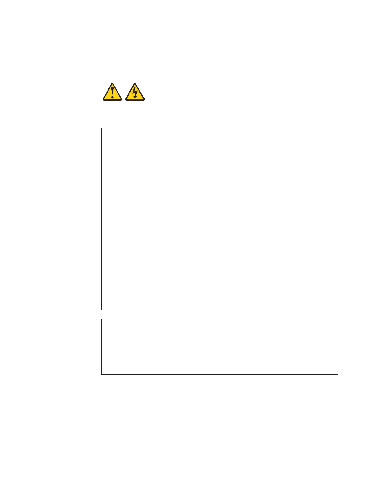
Statement 1:
DANGER
Electrical
current from power, telephone, and communication cables is
hazardous.
To avoid a shock hazard:
v Do not connect or disconnect any cables or perform installation,
maintenance, or reconfiguration of this product during an electrical
storm.
v Connect all power cords to a properly wired and grounded electrical
outlet.
v Connect to properly wired outlets any equipment that will be attached to
this product.
v When possible, use one hand only to connect or disconnect signal
cables.
v Never turn on any equipment when there is evidence of fire, water, or
structural damage.
v Disconnect the attached power cords, telecommunications systems,
networks, and modems before you open the device covers, unless
instructed otherwise in the installation and configuration procedures.
v Connect and disconnect cables as described in the following table when
installing, moving, or opening covers on this product or attached
devices.
To Connect: To Disconnect:
1. Turn everything OFF.
2. First, attach all cables to devices.
3. Attach signal cables to connectors.
4. Attach power cords to outlet.
5. Turn device ON.
vi System x3105 Type 4347: Installation Guide
1. Turn everything OFF.
2. First, remove power cords from outlet.
3. Remove signal cables from connectors.
4. Remove all cables from devices.
Page 9

Statement 2:
CAUTION:
When replacing the lithium battery, use only IBM Part Number 33F8354 or an
equivalent type battery recommended by the manufacturer. If your system has
a module containing a lithium battery, replace it only with the same module
type made by the same manufacturer. The battery contains lithium and can
explode if not properly used, handled, or disposed of.
Do not:
v Throw or immerse into water
v Heat to more than 100°C (212°F)
v Repair or disassemble
Dispose
of the battery as required by local ordinances or regulations.
Safety vii
Page 10
Statement 3:
CAUTION:
When laser products (such as CD-ROMs, DVD drives, fiber optic devices, or
transmitters) are installed, note the following:
v Do not remove the covers. Removing the covers of the laser product could
result in exposure to hazardous laser radiation. There are no serviceable
parts inside the device.
v Use of controls or adjustments or performance of procedures other than
those specified herein might result in hazardous radiation exposure.
DANGER
laser products contain an embedded Class 3A or Class 3B laser
Some
diode. Note the following.
Laser radiation when open. Do not stare into the beam, do not view directly
with optical instruments, and avoid direct exposure to the beam.
Class 1 Laser Product
Laser Klasse 1
Laser Klass 1
Luokan 1 Laserlaite
Appareil A Laser de Classe 1
`
viii System x3105 Type 4347: Installation Guide
Page 11

Statement 4:
≥ 18 kg (39.7 lb) ≥ 32 kg (70.5 lb) ≥ 55 kg (121.2 lb)
CAUTION:
Use safe practices when lifting.
Statement 5:
CAUTION:
The power control button on the device and the power switch on the power
supply do not turn off the electrical current supplied to the device. The device
also might have more than one power cord. To remove all electrical current
from the device, ensure that all power cords are disconnected from the power
source.
2
1
Safety ix
Page 12
Statement 8:
CAUTION:
Never remove the cover on a power supply or any part that has the following
label attached.
Hazardous voltage, current, and energy levels are present inside any
component that has this label attached. There are no serviceable parts inside
these components. If you suspect a problem with one of these parts, contact
a service technician.
Statement 12:
CAUTION:
The following label indicates a hot surface nearby.
Statement 13:
DANGER
Overloading
a branch circuit is potentially a fire hazard and a shock hazard
under certain conditions. To avoid these hazards, ensure that your system
electrical requirements do not exceed branch circuit protection
requirements. Refer to the information that is provided with your device for
electrical specifications.
Important:
Eachl caution and danger statement in this document is labelled begin with a
number. This number is used to cross reference an English-language caution or
danger statement with translated versions of the caution or danger statement in the
Safety Information document.
x System x3105 Type 4347: Installation Guide
Page 13

For example, if a caution statement is labelled ″Statement 1″, translations for that
caution statement are in the Safety Information document under ″Statement 1″.
Be sure to read all caution and danger statements in this documentation before you
perform the procedures. Read any additional safety information that comes with the
server or optional device before you install the device.
Safety xi
Page 14

xii System x3105 Type 4347: Installation Guide
Page 15
Chapter 1. Introduction
This Installation Guide contains instructions for setting up your IBM® System x3105
Type 4347 server and basic instructions for installing some optional devices. More
detailed instructions for installing optional devices are in the User’s Guide on the
IBM System x™ Documentation CD, which comes with the server. This document
contains information about:
v Setting up and cabling the server
v Starting and configuring the server
v Installing some optional devices
v Solving problems
firmware and documentation updates are available, you can download them from
If
the IBM Web site The server might have features that are not described in the
documentation that comes with the server, and the documentation might be updated
occasionally to include information about those features, or technical updates might
be available to provide additional information that is not included in the server
documentation. To check for updates, got to http://www.ibm.com/servers/eserver/
support/xseries/index.html,
Go. For firmware updates, click the Download tab. For documentation updates,
click the Install and use tab, and click Product documentation.
select System x3105 from the Hardware list, and click
Note: Changes are made periodically to the IBM Web site. Procedures for locating
firmware and documentation might vary slightly from what is described in this
document.
(Standard on some models only) The server comes with an IBM ServerGuide
™
Setup and Installation CD to help you configure the hardware, install device drivers,
and install the operating system.
The server comes with a limited warranty. You can obtain up-to-date information
about your server and other IBM server products at http://www.ibm.com/systems/x.
Record information about the server in the following table. You will need this
information when you register the server with IBM.
Product name IBM System x3105 server
Machine type 4347
Model number _____________________________________________
Serial number _____________________________________________
© Copyright IBM Corp. 2007 1
Page 16
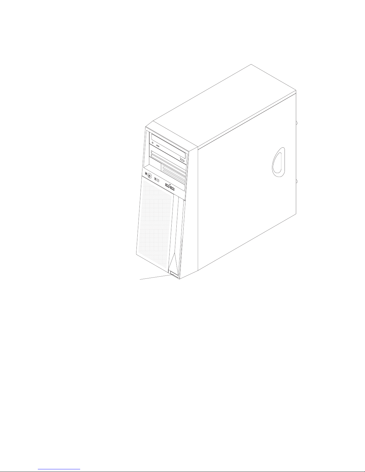
The model number and serial number are on the label on the lower-right side of the
bezel, as shown in the following illustration. This illustration might differ slightly from
your hardware.
Model number and
serial number
For a list of supported optional devices for the server, see http://www.ibm.com/
servers/eserver/serverproven/compat/us.
2 System x3105 Type 4347: Installation Guide
Page 17

The IBM System x Documentation CD
The IBM System x Documentation CD contains documentation for the server in
Portable Document Format (PDF) and includes the IBM Documentation Browser to
help you find information quickly.
Hardware and software requirements
The IBM System x Documentation CD requires the following minimum hardware
and software:
v Microsoft®, Windows XP, Windows 2000, or Red Hat Linux
v 100 MHz microprocessor
v 32 MB of RAM
v Adobe Acrobat Reader 3.0 (or later) or xpdf, which comes with Linux operating
systems.
Using the Documentation Browser
Use the Documentation Browser to browse the contents of the CD, read brief
descriptions of the documents, and view documents, using Adobe Acrobat Reader
or xpdf. The Documentation Browser automatically detects the regional settings in
your server and displays the documents in the language for that region (if
available). If a document is not available in the language for that region, the
English-language version is displayed.
Use one of the following procedures to start the Documentation Browser:
v If Autostart is enabled, insert the CD into the CD or DVD drive. The
Documentation Browser starts automatically.
v If Autostart is disabled or is not enabled for all users, use one of the following
procedures:
– If you are using a Windows operating system, insert the CD into the Cd drive
and click Start --> Run. In the Open field, type
e:\win32.bat
where e is the drive letter of the CD drive, and click OK.
– If you are using Red Hat Linux, insert the CD into the CD drive; then, run the
following command from the /mnt/cdrom directory:
sh runlinux.sh
Select the server from the Product menu. The Available Topics list displays all the
documents for the server. Some documents might be in folders. A plus sign (+)
indicates each folder or document that has additional documents under it. Click the
plus sign to display the additional documents.
When you select a document, a description of the document is displayed under
Topic Description. To select more than one document, press and hold the Ctrl key
while you select the documents. Click View Book to view the selected document or
documents in Acrobat Reader or xpdf. If you selected more than one document, all
the selected documents are opened in Acrobat Reader or xpdf.
To search all the documents, type a word or word string in the Search field and
click Search. The documents in which the word or word string appears are listed in
order of the most occurrences. Click a document to view it, and press Crtl+F to use
the Acrobat search function or Alt+F to use the xpdf search function within the
document.
Chapter 1. Introduction 3
Page 18

Click Help for detailed information about using the Documentation Browser.
Notices and statements in this document
The caution and danger statements in this document are also in the multilingual
Safety Information document, which is on the IBM System x Documentation CD.
Each statement is numbered for reference to the corresponding statement in the
Safety Information document.
The following notices and statements are used in this document:
v Note: These notices provide important tips, guidance, or advice.
v Important: These notices provide information or advice that might help you avoid
inconvenient or problem situations.
v Attention: These notices indicate potential damage to programs, devices, or
data. An attention notice is placed just before the instruction or situation in which
damage could occur.
v Caution: These statements indicate situations that can be potentially hazardous
to you. A caution statement is placed just before the description of a potentially
hazardous procedure step or situation.
v Danger: These statements indicate situations that can be potentially lethal or
extremely hazardous to you. A danger statement is placed just before the
description of a potentially lethal or extremely hazardous procedure step or
situation.
4 System x3105 Type 4347: Installation Guide
Page 19

Features and specifications
The following information is a summary of the features and specifications of the
server. Depending on the server model, some features might not be available, or
some specifications might not apply.
Table 1. Features and specifications
Microprocessor:
v AMD single-core Athlon processor or
dual-core Opteron processor
v 512 KB or 2 MB (1 MB per core)
level-2 cache
v 1000 MHz Hyper-transport (HT)
interface
Memory:
v Minimum: 512 MB
v Maximum: 8 GB
v Types: Unbuffered PC2-5300,
double-data-rate 2 (DDR2) 667 MHz
with ECC
v Connectors: four dual inline memory
module (DIMM) connectors, two-way
interleaved
(depending on your model)
Drives:
v Diskette: (optional) 1.44 MB
v Hard disk drive: SATA
v Optional tape drive: SATA
v One of the following IDE drives:
– CD-ROM
– CD-RW (optional)
– DVD-ROM (optional)
– DVD/CD-RW combo (optional)
bays: (depending on your model)
Drive
v Two 5.25 in. bays (one CD or DVD
drive installed)
v One 3.5 in. removable-media drive
bay; optional internal diskette drive
v Two 3.5 in. hard disk drive bays (one
hard disk drive installed)
Expansion
slots:
v Two PCI Express x8 slots
v Two PCI 33 MHz/32-bit slots
Video controller: ATI ES1000 video
controller with 16 MB SDRAM video
memory on the system board
Fans:
One speed-controlled fan
Power supply: One 310 watt (90 - 240 V
ac)
Important: Make sure that the ac
power-supply input voltage is set to the
correct level (at 115 V ac or 230 V ac) for
your geographic location before you turn
on the server.
Size:
v Height: 420 mm (16.54 in.)
v Depth: 448 mm (17.64 in.)
v Width:175 mm (6.89 in.)
v Weight: 14 kg (30.86 lb) to 17 kg (37.48
lb) depending upon configuration
Integrated
v Broadcom 5721 10/100/1000 Ethernet
controller on the system board with
RJ-45 Ethernet port
v One serial port
v One parallel port
v Two-port Serial ATA controller
v Six Universal Serial Bus (USB) v2.0
ports (two on front and four on rear)
v ATA-100 single-channel IDE controller
v ATI ES1000 video
– Compatible with SVGA and VGA
– 16 MB video memory
Diagnostic LEDs:
v Fans
v Memory
Acoustical noise emissions:
v Sound power, idling: 4.3 bel
v Sound power, operating: 4.8 bel
functions:
Environment:
v Air temperature:
– Server on: 10° to 35°C (50° to 95°F)
Altitude: 0 to 914 m (2998.0 ft)
– Server off: 0° to 60°C (-32° to 140°F)
Altitude: 0 to 2133 m (7000.0 ft)
Humidity (operating and storage): 8% to
v
80%
output:
Heat
Approximate heat output in British thermal
units (Btu) per hour
v Minimum configuration: 185 Btu per hour
(54 watts)
v Maximum configuration: 853 Btu per hour
(250 watts)
Electrical
input:
v Sine-wave input (50 or 60 Hz) required
v Input voltage and frequency ranges
manually selected
v Input voltage low range:
– Minimum: 100 V ac
– Maximum: 127 V ac
Input voltage high range:
v
– Minimum: 200 V ac
– Maximum: 240 V ac
v Input kilovolt-amperes (kVA) approximately:
– Minimum: 0.10 kVA (all models)
– Maximum: 0.50 kVA
Notes:
1. Power consumption and heat output vary
depending on the number and type of
optional features that are installed and the
power-management optional features that
are in use.
2. These levels were measured in controlled
acoustical environments according to the
procedures that are specified by the
American National Standards Institute
(ANSI) S12.10 and ISO 7779 and are
reported in accordance with ISO 9296.
Actual sound-pressure levels in a given
location might exceed the average values
stated because of room reflections and
other nearby noise sources. The declared
sound-power levels indicate an upper limit,
below which a large number of computers
will operate.
Chapter 1. Introduction 5
Page 20
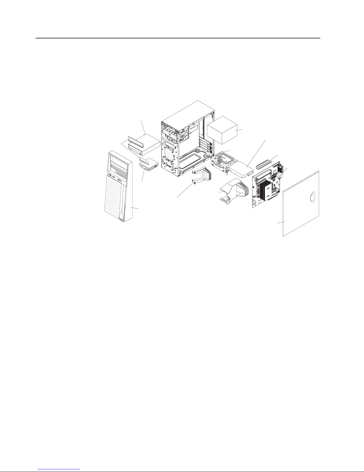
Major components of the server
Blue on a component indicates touch points, where you can grip the component to
remove it from or install it in the server, open or close a latch, and so on.
The following illustration shows the major components in the server.
Note: The illustrations in this document might differ slightly from your hardware.
CD or DVD
drive
Filler panels
(Optional)
diskette drive
Bezel
Front adapter
retention bracket
Air baffle
Power supply
Drive cage
Hard disk drive
DIMM
System board
Cover
6 System x3105 Type 4347: Installation Guide
Page 21

Chapter 2. Installing optional devices
This chapter provides basic instructions for installing optional hardware devices in
the server. These instructions are intended for users who are experienced with
setting up IBM server hardware. If you need more detailed instructions, see the
User’s Guide on the IBM System x Documentation CD.
Installation guidelines
Before you install optional devices, read the following information:
v Read the safety information that begins on page v and the guidelines in
“Handling static-sensitive devices” on page 8. This information will help you work
safely.
v When you install your new server, take the opportunity to download and apply
the most recent firmware updates. This step will help to ensure that any known
issues are addressed and that your server is ready to function at maximum levels
of performance. To download firmware updates for your server, go to
http://www.ibm.com/servers/eserver/support/xseries/index.html, select System
x3105 from the Hardware list, click Go, and then click the Download tab. For
additional information about tools for updating, managing, and deploying
firmware, see the System x and xSeries Tools Center at
http://publib.boulder.ibm.com/infocenter/toolsctr/v1r0/index.jsp.
v Before you install optional hardware devices, make sure that the server is
working correctly. Start the server, and make sure that the operating system
starts, if an operating system is installed, or that a 19990305 error code is
displayed, indicating that an operating system was not found but the server is
otherwise working correctly. If the server is not working correctly see Chapter 5,
“Solving problems,” on page 39 for diagnostic information.
v Observe good housekeeping in the area where you are working. Place removed
covers and other parts in a safe place.
v If you must start the server while the cover is removed, make sure that no one is
near the server and that no tools or other objects have been left inside the
server.
v Do not attempt to lift an object that you think is too heavy for you. If you have to
lift a heavy object, observe the following precautions:
– Make sure that you stand safely without slipping.
– Distribute the weight of the object equally between your feet.
– Use a slow lifting force. Never move suddenly or twist when you lift a heavy
object.
– To avoid straining the muscles in your back, lift by standing or by pushing up
with your leg muscles.
Make sure that you have an adequate number of properly grounded electrical
v
outlets for the server, monitor, and other devices.
v Back up all important data before you make changes to disk drives.
v Have a small flat-blade screwdriver available.
v Blue on a component indicates touch points, where you can grip the component
to remove it from or install it in the server, open or close a latch, and so on.
v When you have to access the inside of the server, you might findit easier to lay
the server on its side.
v When you are finished working on the server, reinstall all safety shields, guards,
labels, and ground wires.
© Copyright IBM Corp. 2007 7
Page 22

v For a list of supported optional devices for the server, see http://www.ibm.com/
servers/eserver/serverproven/compat/us/.
System reliability guidelines
To help ensure proper cooling and system reliability, make sure that the following
requirements are met:
v Each of the drive bays has a drive or a filler panel and electromagnetic
compatibility (EMC) shield installed in it.
v There is adequate space around the server to allow the server cooling system to
work properly. Leave approximately 50 mm (2.0 in.) of open space around the
front and rear of the server. Do not place objects in front of the fans. For proper
cooling and airflow, replace the server cover before turning on the server.
Operating the server for extended periods of time (more than 30 minutes) with
the server cover removed might damage server components.
v Yo u have followed the cabling instructions that come with optional adapters.
v Yo u do not operate the server with a failed fan.
v Yo u do not operate the server without the air baffle installed. Operating the
server without the air baffle might cause the microprocessor to overheat.
Handling static-sensitive devices
Attention: Static electricity can damage the server and other electronic devices.
To avoid damage, keep static-sensitive devices in their static-protective packages
until you are ready to install them.
To reduce the possibility of damage from electrostatic discharge, observe the
following precautions:
v Limit your movement. Movement can cause static electricity to build up around
you.
v The use of a grounding system is recommended. For example, wear an
electrostatic-discharge wrist strap, if one is available.
v Handle the device carefully, holding it by its edges or its frame.
v Do not touch solder joints, pins, or exposed circuitry.
v Do not leave the device where others can handle and damage it.
v While the device is still in its static-protective package, touch it to an unpainted
metal part of the server for at least 2 seconds. This drains static electricity from
the package and from your body.
v Remove the device from its package and install it directly into the server without
setting down the device. If it is necessary to set down the device, put it back into
its static-protective package. Do not place the device on the server cover or on a
metal surface.
v Take additional care when handling devices during cold weather. Heating reduces
indoor humidity and increases static electricity.
8 System x3105 Type 4347: Installation Guide
Page 23
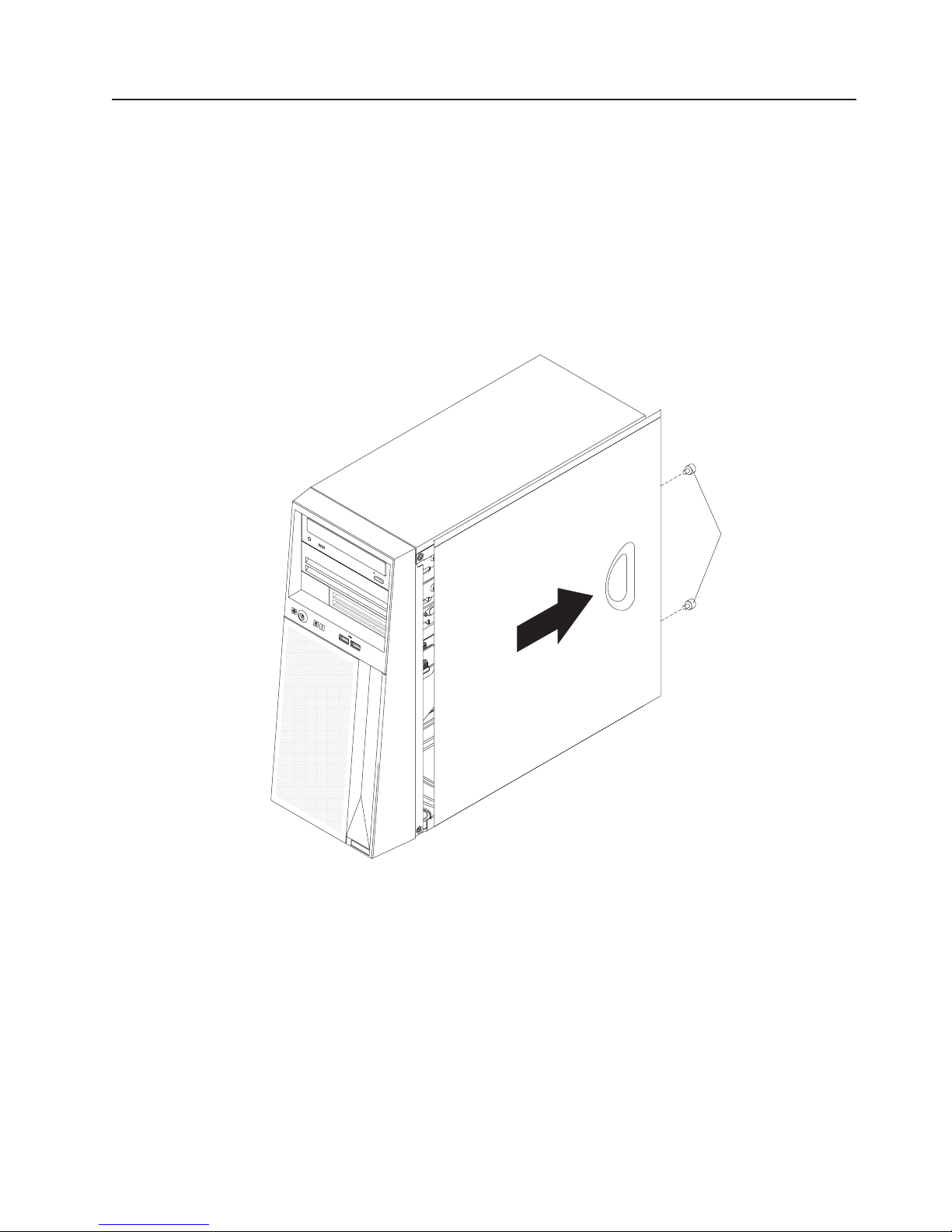
Removing the side cover
To remove the server side cover, complete the following steps:
1. Read the safety information that begins on page v and the “Installation
guidelines” on page 7.
2. Turn off the server and all attached devices (see “Turning off the server” on
page 33); then, disconnect all power cords and external cables.
3. Lay the server on its side.
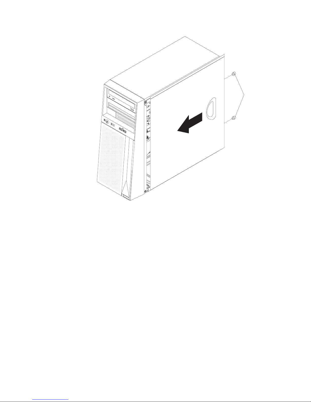
4. Remove the two thumbscrews from the rear of the server that secure the cover
to the chassis. Slide the cover slightly toward the rear of the chassis, lift it off
the server, and set it aside.
Thumbscrews
To replace the side cover, see “Installing the side cover” on page 26.
Attention: For proper cooling and airflow, replace the cover before you turn on
the server. Operating the server for extended periods of time (more than 30
minutes) with the cover removed might damage serve components.
Chapter 2. Installing optional devices 9
Page 24
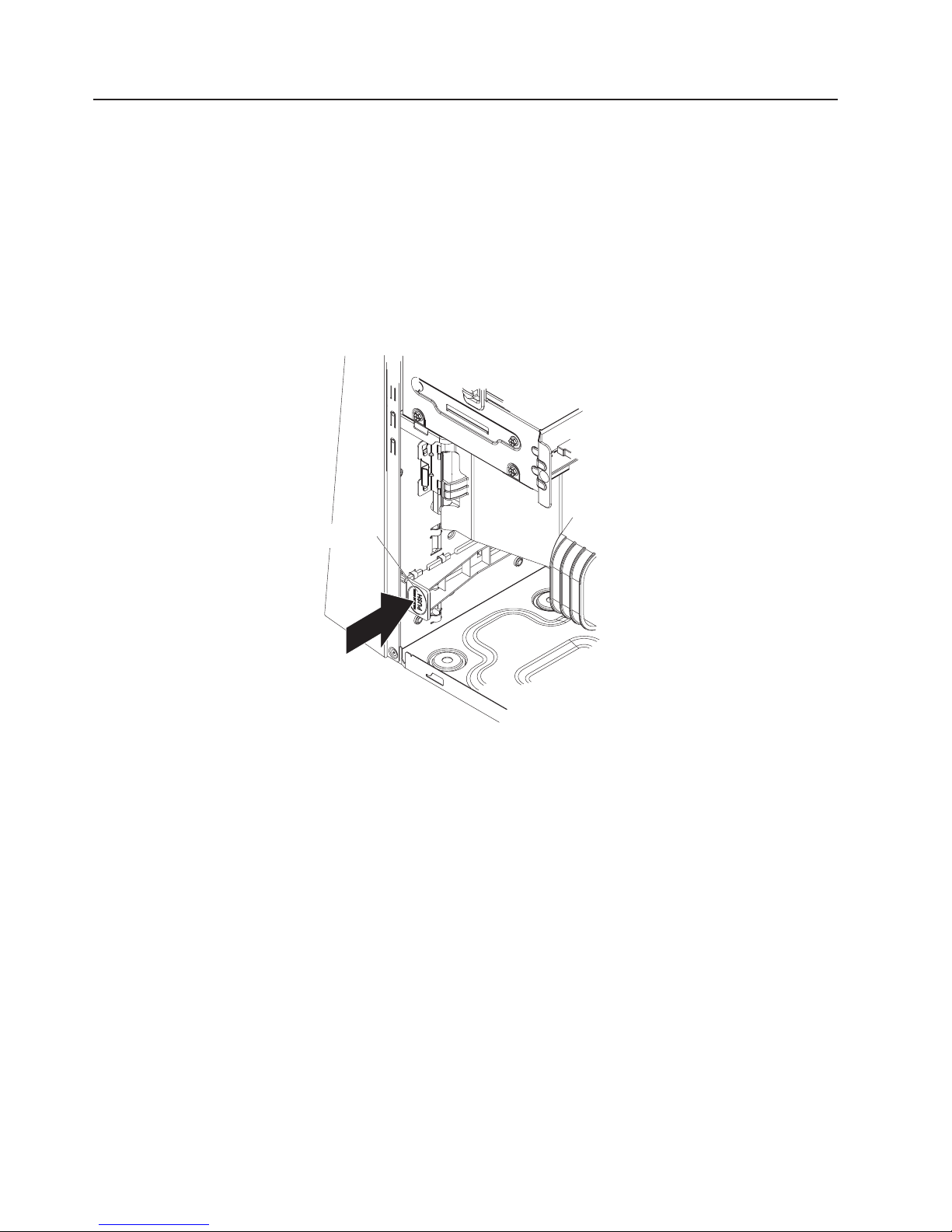
Removing the bezel
When you work with some devices, such as additional optical drives, you must first
remove the bezel to access the device.
To remove the bezel, complete the following steps:
1. Read the safety information that begins on page v and the “Installation
guidelines” on page 7.
2. Turn off the server and all attached devices (see “Turning off the server” on
page 33); then, disconnect all power cords and external cables.
3. Remove the side cover (see “Removing the side cover” on page 9).
4. From inside the server, locate the bezel release tab at the bottom of the bezel.
Bezel release tab
5. Press down slightly on the bezel release tab and pull the bottom of the bezel
away from the chassis; then, lift the bezel to disengage the top tabs.
6. Remove the bezel from the server; then set the bezel aside.
For instructions for replacing the bezel, see “Installing the bezel” on page 25.
10 System x3105 Type 4347: Installation Guide
Page 25

Installing a memory module
The following notes describe the types of dual inline memory modules (DIMMs) that
the server supports and other information that you must consider when installing
DIMMs:
v Install only 1.8 V, 240-pin, double-data-rate 2 (DDR2), 667 MHz, unbuffered
synchronous dynamic random-access memory (SDRAM) with error correcting
code (ECC) DIMMs. These DIMMs must be compatible with the latest PC2-5300,
667 MHz SDRAM unbuffered DIMM specification. For a list of supported DIMMs
for your server, see http://www.ibm.com/servers/eserver/serverproven/compat/us/.
v The server supports a maximum of two hard disk drives, four DIMMs, and one
5.25-inch device; or one hard disk drive, four DIMMs, and two 5.25-inch devices;
or two hard disk drives, two DIMMS, and two 5.25-inch devices.
v The system board contains four DIMM connectors and supports two-way memory
interleaving.
v Yo u can install one, two, or four DIMMs in the server, but not three DIMMs.
Three DIMMs are not supported.
v The DIMM options that are available for the server are 512 MB, 1 GB, and 2 GB.
The server supports a minimum of 512 MB and a maximum of 8 GB of system
memory.
v The amount of usable memory will be reduced depending on the system
configuration. A certain amount of memory must be reserved for system
resources. The system summary displays the total amount of installed memory
and the amount of configured memory.
v The server comes with one 512 MB or two 512 MB DIMMs. If the server has one
DIMM installed, when you install an additional DIMM, it must be installed in the
DIMM 2 connector, and it must be the same size, speed, type, and technology as
the DIMM in the DIMM 1 connector. Yo u can mix compatible DIMMs from various
manufacturers. When one DIMM is installed, the server runs as a single-channel
server. When you add a DIMM in the DIMM 2 connector, the server defaults to a
dual-channel server.
v DIMMs must be installed in matched pairs. If you install a second pair of DIMMs
in the DIMM 3 and DIMM 4 connectors, they do not have to be the same size,
speed, type, and technology as the DIMMs in the DIMM 1 and DIMM 2
connectors. However, the size, speed, type, and technology of the DIMMs that
you install in the DIMM 3 and DIMM 4 connectors must match each other.
v When you restart the server after you add or remove a DIMM, the server
displays a message that the memory configuration has changed.
Chapter 2. Installing optional devices 11
Page 26

To install a DIMM, complete the following steps:
1. Locate the DIMM connectors on the system board. Determine the connectors
into which you will install the DIMMs. Install the DIMMs in the sequence shown
in the following table.
DIMM 1 DIMM 1 error LED
DIMM 2 DIMM 2 error LED
DIMM 3 DIMM 3 error LED
DIMM 4 DIMM 4 error LED
DIMMs Connectors
1 DIMM 1
2 DIMMs 1, 2
4 DIMMs 1, 2, 3, 4
Note: Yo u can install one, two, or four DIMMs in the server, but not three DIMMs. Three
DIMMs are not supported.
12 System x3105 Type 4347: Installation Guide
Page 27

Attention: To avoid breaking the retaining clips or damaging the DIMM
connectors, open and close the clips gently.
2. Open the retaining clips and, if necessary, remove any existing DIMM.
3. Touch the static-protective package that contains the DIMM to any unpainted
metal surface on the server. Then, remove the new DIMM from the package.
4. Turn the DIMM so that the DIMM keys align correctly with the slot.
5. Insert the DIMM into the connector by aligning the edges of the DIMM with the
slots at the ends of the DIMM connector. Firmly press the DIMM straight down
into the connector by applying pressure on both ends of the DIMM
simultaneously. The retaining clips snap into the locked position when the DIMM
is firmly seated in the connector. If there is a gap between the DIMM and the
retaining clips, the DIMM has not been correctly installed. Open the retaining
clips, remove the DIMM, and then reinsert it.
If you have other devices to install or remove, do so now; otherwise, go to
“Completing the installation” on page 25.
Chapter 2. Installing optional devices 13
Page 28
Installing a drive
Depending on the server model, one or more of the following drives might be
installed in the server:
v Diskette (optional)
v Tape drive (optional)
v Hard disk drive
v CD-ROM, CD-RW, or DVD/CD-RW combo
The server might come with an IDE CD or DVD drive in bay 1 and a 3.5-inch serial
ATA (SATA) hard disk drive in bay 4.
Bay 1
Bay 2
Bay 3
Bay 4
Bay 5
The following notes describe the types of drives that the server supports and other
information that you must consider when you install removable-media and hard disk
drives:
v Read the documentation that comes with the drive and make sure that you have
all the cables and other equipment specified in the documentation that comes
with the drive.
v The server supports a maximum configuration of two hard disk drives, four
DIMMs, and one 5.25-inch device; or one hard disk drive, four DIMMs, and two
5.25-inch devices; or two hard disk drives, two DIMMS, and two 5.25-inch
devices.
v Diskette drives, tape drives, CD-ROM, and CD-RW/DVD combo drives are
examples of removable-media drives. You can install removable-media drives in
bays 1, 2, and 3 only.
14 System x3105 Type 4347: Installation Guide
Page 29
v Yo u can install only an optional diskette drive in bay 3. Other drives are not
supported in bay 3.
v Yo u can install SATA hard disk drives in bays 4 and 5 only.
v The integrated IDE controller supports the connection of up to two IDE devices.
v The electromagnetic interference (EMI) integrity and cooling of the server are
protected by having all bays and PCI or PCI Express slots covered or occupied.
When you install a drive or PCI or PCI Express adapter, save the EMC shield
and filler panel from the bay, or the PCI or PCI Express adapter slot cover in the
event you later remove the drive or adapter.
v For a complete list of supported optional devices for the server, see
http://www.ibm/com/servers/eserver/serverproven/compat/us/.
Installing a CD or DVD drive
To install a CD or DVD drive in bay 1 or 2, complete the following steps:
1. Read the safety information that begins on page v and “Installation guidelines”
on page 7.
2. Turn off the server and peripheral devices, and disconnect the power cords
and all external cables.
3. Remove the side cover (see “Removing the side cover” on page 9).
4. Remove the bezel (see “Removing the bezel” on page 10).
5. Use your fingers to press in on the drive-bay filler panel release tab on the
inside of the bezel and remove it from the bezel; then, pry the EMC shield
away from the server. Store the filler panel and EMC shield in a safe place.
Release tab
Chapter 2. Installing optional devices 15
Page 30

EMC shield
Drive retainer clip
Note: If you are installing a drive that contains a laser, observe the following
safety precaution.
16 System x3105 Type 4347: Installation Guide
Page 31

Statement 3
CAUTION:
When laser products (such as CD-ROMs, DVD drives, fiber optic devices, or
transmitters) are installed, note the following:
v Do not remove the covers. Removing the covers of the laser product could result in
exposure to hazardous laser radiation. There are no serviceable parts inside the
device.
v Use of controls or adjustments or performance of procedures other than those
specified herein might result in hazardous radiation exposure.
Danger
Some laser products contain an embedded Class 3A or Class 3B laser diode. Note the
following. Laser radiation when open. Do not stare into the beam, do not view directly with
optical instruments, and avoid direct exposure to the beam.
Class 1 Laser Product
Laser Klasse 1
Laser Klass 1
Luokan 1 Laserlaite
Appareil A Laser de Classe 1
6. Touch the static-protective package that contains the drive to any unpainted
`
metal surface on the server; then, remove the drive from the package and
place it on a static-protective surface.
7. Set any jumpers or switches on the drive according to the documentation that
comes with the drive.
8. Remove the drive retainer clip (on the front of the chassis). Slide the clip to the
right to remove it from the chassis; then, snap the clip into the screw holes on
the side of the drive (the blue side of the drive clip should be facing outward).
9. Align the drive assembly with the guide rails in the bay. Push the drive into the
bay.
10. Connect one end of the signal cable into the back of the drive and make sure
that the other end of this cable is connected into the IDE connector on the
system board. See ″System-board internal connectors″ in the User’s Guide for
the connector locations on the system board.
11. Route the signal cable so that it does not block the airflow to the rear of the
drives or over the microprocessor and DIMMs.
12. Connect the power cable to the back of the drive. The connectors are keyed
and can be inserted only one way.
If you have other devices to install or remove, do so now; otherwise, go to
“Completing the installation” on page 25.
Chapter 2. Installing optional devices 17
Page 32
Installing an optional tape drive
To install an optional tape drive, complete the following steps:
1. Read the safety information that begins on page v and “Installation guidelines”
on page 7.
2. Turn off the server and peripheral devices, and disconnect the power cords and
all external cables.
3. Remove the side cover (see “Removing the side cover” on page 9).
4. Remove the bezel (see “Removing the bezel” on page 10).
5. Use your fingers to press in on the drive-bay filler panel release tab on the
inside of the bezel and remove it from the bezel; then, pry the EMC shield away
from the server. Store the filler panel and EMC shield in a safe place.
Release tab
18 System x3105 Type 4347: Installation Guide
Page 33

EMC shield
6. Touch the static-protective package that contains the drive to any unpainted
metal surface on the server; then, remove the tape drive from the package and
place it on a static-protective surface.
7. Slide the tape drive into the drive cage from the front of the server; then,
connect the SATA cable to the tape drive.
8. Secure the tape drive to the chassis with the supplied screws.
9. Connect the tape drive cable to the tape drive connector on the system board.
If you have other devices to install or remove, do so now; otherwise, go to
“Completing the installation” on page 25.
Installing a SATA hard disk drive
The server comes with one Serial ATA (S ATA) hard disk drive installed. Before you
install a SATA hard disk drive, read the following information:
v Read the documentation that comes with the drive for cabling instructions.
v Route the cable before you install the drive. Do not block the airflow from the fan.
v The server supports two SATA hard disk drives.
Note: Each SATA drive comes with a cable. If you install an additional S ATA
drive, you will need an additional cable. If you install an optional
ServeRAID-7t S-ATA controller, all SATA drives must be connected to the
ServeRAID-7t S-ATA controller instead of the system board. The controller
comes with two cables. See the ServeRAID-7t S-ATA controller
documentation for cabling instructions. You can install a ServeRAID-7t
S-ATA controller in slot 3 or slot 4.
install a SATA hard disk drive in bay 4 or 5, complete the following steps:
To
1. Read the safety information that begins on page v and the “Installation
guidelines” on page 7.
Chapter 2. Installing optional devices 19
Page 34

2. Turn off the server and peripheral devices and disconnect all external cables
and power cords.
3. Remove the side cover (see “Removing the side cover” on page 9).
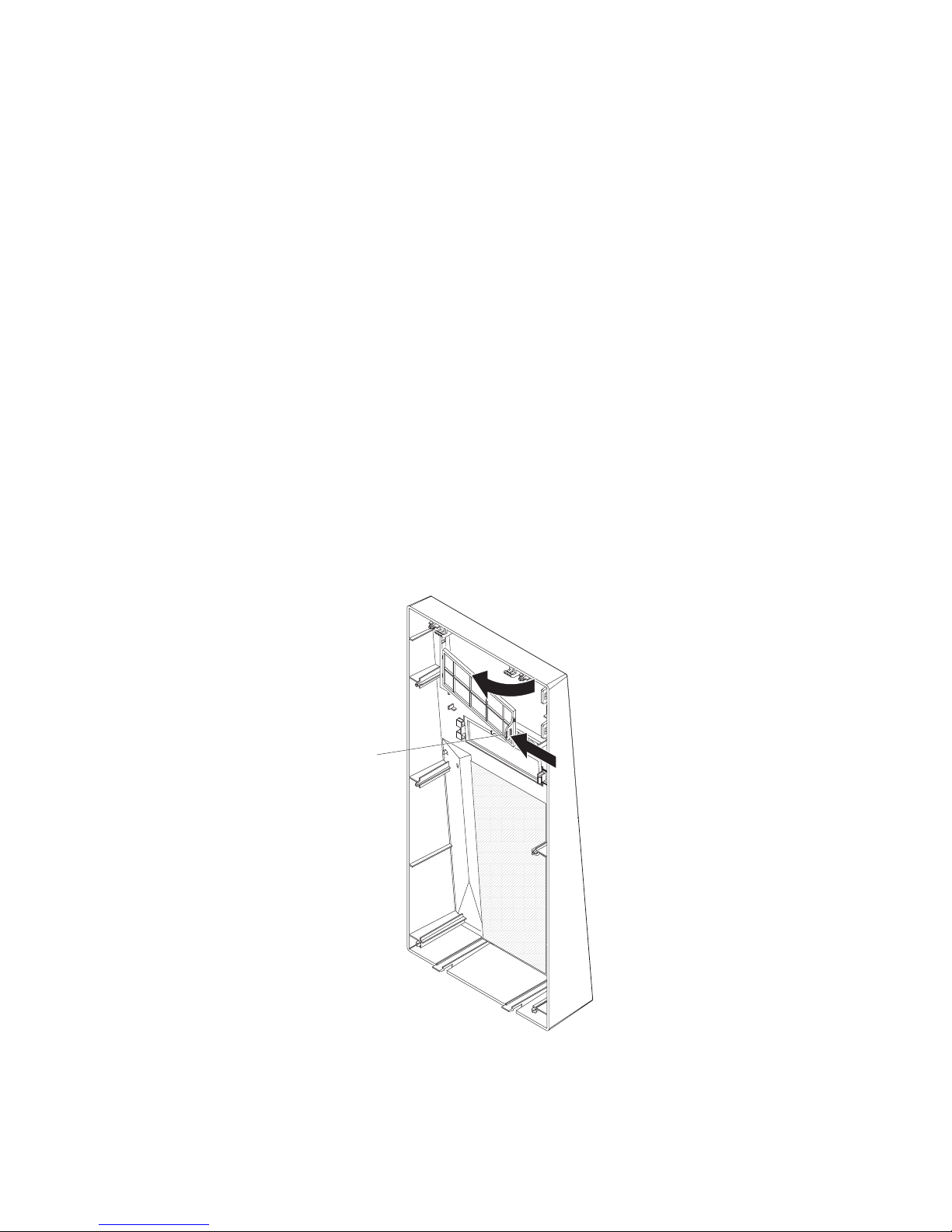
4. Grasp the hard disk drive cage and rotate it up until it locks into place on the
chassis.
5. Rotate the drive cage upward and out of the server until it snaps into the open
position.
Note: You can remove the drive cage from the server by lifting up and gently
pulling it out of the server. It is not necessary to remove the drive cage
to install the drive.
Locking latch
Thumbscrew
6. Touch the static-protective package that contains the drive to any unpainted
metal surface on the server; then, remove the drive from the package and
place it on a static-protective surface.
Note: If the hard disk drive comes attached to a drive tray, remove the drive
from the drive tray before you install the drive in the drive bay.
7. Set any jumpers or switches on the drive according to the documentation that
comes with the drive.
8. Align the drive assembly with the guide rails in the bay (with the connector end
of the drive facing you).
9. Gently slide the drive assembly into the drive bay as far as it will go.
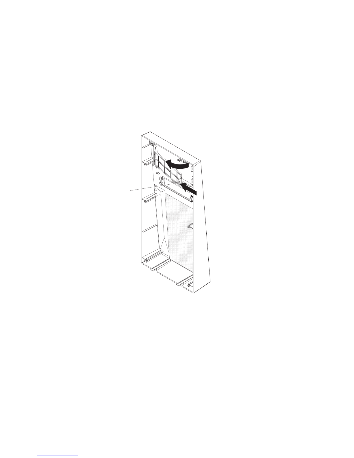
10. Attach the hard disk drive to the drive cage with the four screws.
11. Press in on the locking latch and rotate the drive cage back into the server,
12. Secure the drive cage to the chassis with the blue thumbscrew that you
removed earlier.
13. Connect one end of the signal cable into the back of the drive and make sure
that the other end of the cable is connected into the connector on the system
20 System x3105 Type 4347: Installation Guide
Page 35

board. See “Power and signal cables for internal drives” on page 22 for
additional information about cabling drives and “System-board internal
connectors” in the User’s Guide for the location of the SATA connectors on the
system board. If there are open connectors on the cables that connect existing
SATA drives, you can use these cables to connect the new drive.
14. Route the signal cable so that it does not block the airflow to the rear of the
drives or over the microprocessor and DIMMs.
15. Connect the power cable to the back of the drive. The connectors are keyed
and can be inserted only one way.
If you have other devices to install or remove, do so now. Otherwise, go to
“Completing the installation” on page 25.
Chapter 2. Installing optional devices 21
Page 36

Power and signal cables for internal drives
The server uses cables to connect parallel IDE, Serial ATA , and SCSI devices (such
as tape drives) to the power supply and to the system board. (See the User’s Guide
for the location of system-board internal connectors.) Review the following
information before you connect power and signal cables to internal drives:
v The drives that are preinstalled in the server come with attached power and
signal cables. If you replace any drives, remember which cable is attached to
which drive.
v When you install a drive, make sure that one of the signal cable drive connectors
is connected to the drive and that the connector at the other end of the signal
cable is connected to the system board.
v If only one IDE device is connected to a cable, it must be set as a master device.
v If two IDE devices are used on a single cable, one must be designated as the
master device and the other as the subordinate device; otherwise, the server
might not recognize some of the IDE devices. The master and subordinate
designation is determined by switch or jumper settings on each IDE device.
The following cables are provided:
v Power cables: Four-wire power cables connect the drives to the power supply.
At the end of these cables are plastic connectors that can be attached to
different drives; these connectors vary in size. Use either a four-wire power cable
or Serial ATA power cable with Serial ATA drives, but do not use both at the
same time (use one or the other).
v Signal cables: Signal cables are typically flat cables, also called ribbon cables,
that connect parallel IDE, Serial ATA , and diskette drives to the system board.
Two or three types of signal cables come with the server:
– IDE: The wider IDE signal cable has three connectors. One of these
connectors is attached to the drive, one is a spare, and the third is attached to
the primary or secondary IDE connector on the system board. The spare
connector can be used to connect an additional IDE drive to the server.
The CD or DVD drive is attached to an ATA 100 signal cable. ATA 100 signal
cables are color-coded. The blue connector is attached to the system board.
The black connector is attached to the master IDE device. The gray middle
connector is attached to the subordinate IDE device.
– (Optional) Diskette drive: The narrower signal cable has two connectors.
One is attached to the diskette drive, and the other is connected to the
connector (J17) on the system board.
– Serial ATA (SATA): The narrower, black signal cable has two connectors. One
is connected to the Serial ATA drive, and the other is attached to the
connector on the system board. Each Serial ATA drive comes with a cable. If
you install an additional Serial ATA drive, you will need an additional cable.
If you install an optional ServeRAID-7t S-ATA controller, all SATA drives must
then be connected to the ServeRAID-7t S-ATA controller instead of the system
board. The controller comes with two cables. See the ServeRAID-7t S- ATA
controller documentation for cabling instructions.
– SCSI: A SCSI cable connects external SCSI devices to an optional SCSI
controller. For more information about connecting SCSI devices, see the SCSI
documentation.
22 System x3105 Type 4347: Installation Guide
Page 37

Installing an adapter
The following notes describe the types of adapters that the server supports and
other information that you must consider when you install an adapter:
v Locate the documentation that comes with the adapter and follow those
instructions in addition to the instructions in this section. If you must change the
switch setting or jumper settings on the adapter, follow the instructions that come
with the adapter.
v Read the documentation that comes with the operating system.
v The server has two PCI Express slots and two PCI slots.
v Yo u can install full-length adapters in PCI Express slots 1 and 2.
v Yo u can install only 32-bit/33 MHz adapters in PCI slots 3 and 4.
v The 32-bit PCI slots 3 and 4 support 5.0 V signaling PCI adapters; they do not
support 3.3 V keyed adapters. However, 64-bit adapters are supported if they are
universal adapters.
v PCI Express x8 slots 1 and 2 support any PCI Express adapter that is on the
ServerProven list.
v The server scans the PCI Express slots ( slots 1 and 2), and PCI slots (slots 3
and 4) to assign system resources. Then, the server starts the PCI and PCI
Express devices in the following order, if you have not changed the default
startup sequence: PCI Express slot 1, PCI Express slot 2, system-board
integrated drive electronics (IDE) or SCSI devices, and then PCI slots 3 and 4.
v For a list of supported optional devices for the server, see http://www.ibm.com/
servers/eserver/serverproven/compat/us/.
To install an adapter, complete the following steps:
1. Read the safety information that begins on page v and “Installation guidelines”
on page 7.
2. Turn off the server and peripheral devices and disconnect all external cables
and power cords; then, remove the side cover. See “Removing the side cover”
on page 9.
3. Follow the instructions that come with the adapter for requirements,
restrictions, or cabling instructions. It might be easier to route any cables
before you install the adapter.
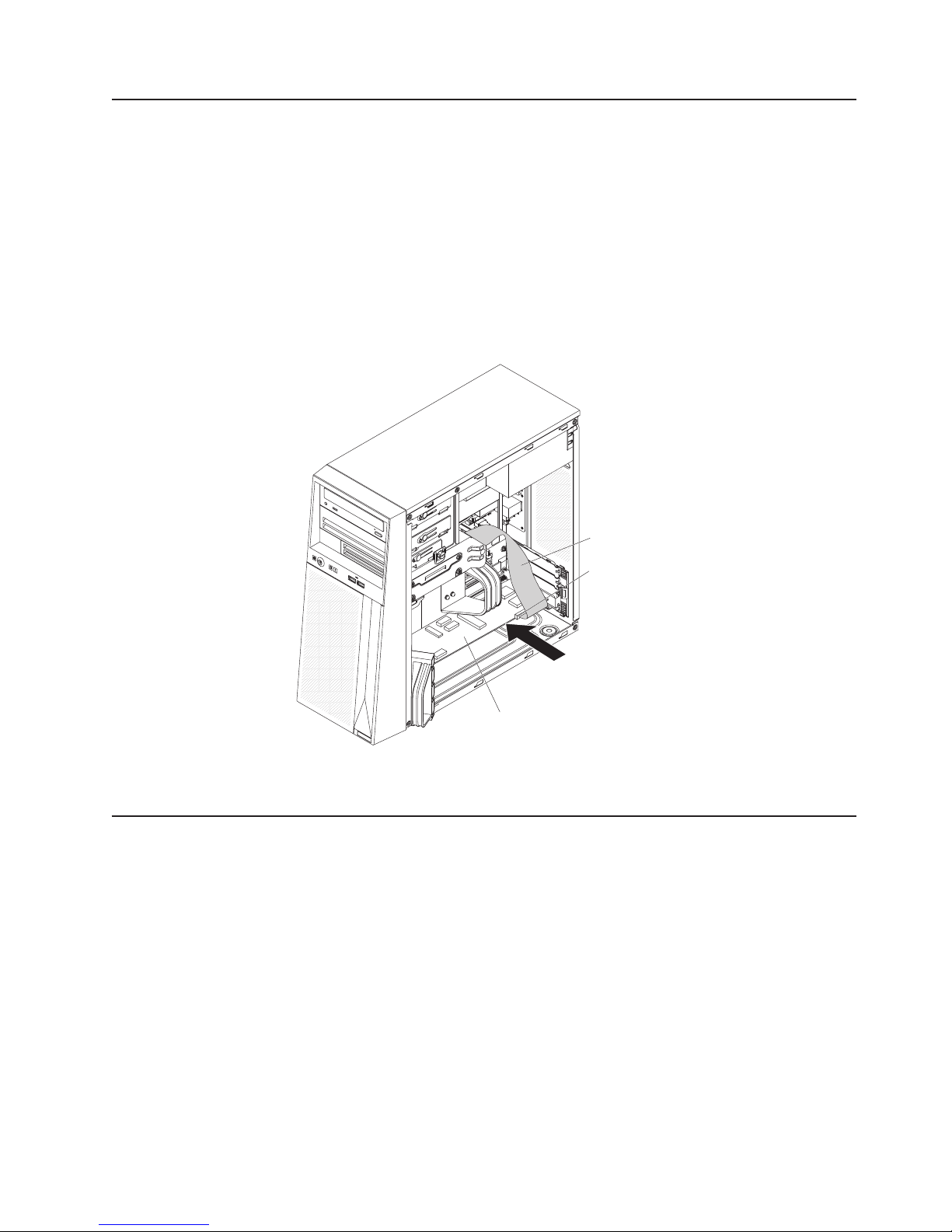
4. Lift up the front adapter retention bracket.
5. From inside the server, press down on the rear adapter retention bracket. The
retention bracket springs open. Reach inside the server and remove the
expansion-slot cover from the expansion slot. Store it in a safe place for future
use.
Note: Expansion-slot covers must be installed on all vacant slots. This
maintains the electronic emissions standards of the server and ensures
proper ventilation of server components.
6. Touch the static-protective package that contains the adapter to any unpainted
metal surface on the server. Then, remove the adapter from the
static-protective package.
Attention: Avoid touching the components and gold-edge connectors on the
adapter.
7. Follow the instructions that come with the adapter to set jumpers or switches, if
any.
Chapter 2. Installing optional devices 23
Page 38

8. Carefully grasp the adapter by the top edge or upper corners, and align it with
the expansion-slot guides; then, press the adapter firmly into the expansion
slot. Move the adapter directly from the static-protective package to the
expansion slot.
Attention: Make sure that the adapter is correctly seated in the expansion
slot before you turn on the server. Incomplete installation of an adapter might
damage the system board or the adapter.
Rear adapter
retention
bracket
Expansion slot
cover
Front adapter
retention
9. Close the adapter retainer bracket.
bracket
10. Connect required cables to the adapter. Route cables so that they do not block
the flow of air from the fan. If you are installing an optional SCSI adapter, see
“Cabling an optional SCSI adapter” on page 25 for additional information.
If you have other devices to install, do so now. Otherwise go to “Completing the
installation” on page 25.
24 System x3105 Type 4347: Installation Guide
Page 39
Cabling an optional SCSI adapter
You can install an optional SCSI adapter in the server to control an internal tape
drive. You can also cable a SCSI adapter to external hard disk drives. See the
SCSI adapter documentation for complete instructions for installing a SCSI adapter
in the server and for additional information about SCSI adapters.
Note: A SCSI adapter and cable are required to connect external SCSI devices.
To cable an optional SCSI adapter, complete the following steps:
1. Install the SCSI adapter (see “Installing an adapter” on page 23).
2. Connect the SCSI signal cable to the adapter and to one or more of the
connectors on the rear of the SCSI devices.
3. Complete the installation of the optional SCSI adapter (see “Installing an
adapter” on page 23).
Completing the installation
To complete the installation, you must reinstall the bezel, reinstall the side cover,
connect all the cables and, for certain optonal devices, run the Configuration/Setup
Utility program. Follow the instructions in this section.
Installing the bezel
To replace the bezel, complete the following steps:
1. Insert the two alignment tabs at the top of the bezel into the bezel retention
slots at the top of the chassis.
SCSI cable
SCSI connector
SCSI adapter
Chapter 2. Installing optional devices 25
Page 40

Bezel
alignment
tabs
Bezel
retention
slots
2. Push the bottom of the bezel toward the server until the bezel snaps into place.
Installing the side cover
Note: You might find it easier to lay the server on its side to replace the side cover.
To replace the side cover, complete the following steps:
1. Make sure that all cables, adapters, and other components are installed and
seated correctly and that you have not left loose tools or parts inside the server.
2. Align the cover over the server (with the rear of the cover slightly hanging off
the rear of the server) and slide the cover toward the front of the server until it
is completely closed.
26 System x3105 Type 4347: Installation Guide
Page 41
Thumbscrews
3. Use the two thumbscrews that you removed earlier to secure the cover to the
server chassis.
Connecting the cables
If the server cables and connector panel have color-coded connectors, match the
color of each cable end with the color of the connector. For example, match a blue
cable end with a blue connector on the connector panel, a red cable end with a red
connector, and so on.
Attention: To prevent damage to equipment, connect the power cords last.
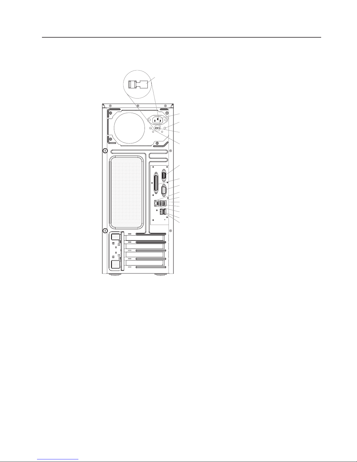
The following illustration shows the input/output (I/O) connectors on the rear of the
server.
Chapter 2. Installing optional devices 27
Page 42

115
Power-supply
voltage switch
115
Power cord connector
Power-supply error LED
Power-supply voltage switch
AC power LED
Video connector
Parallel connector
Serial connector
Ethernet link status LED
USB 4 connector
Ethernet
USB 3 connector
Ethernet activity LED
USB 2 connector
USB 1 connector
Updating the server configuration
When you start the server for the first time after you add or remove an external
SCSI device, you might receive a message that the configuration has changed. The
Configuration/Setup Utility program starts automatically so that you can save the
new configuration settings. See Chapter 4, “Configuring the server,” on page 35 for
additional information.
Some devices have device drivers that you must install. See the documentation that
comes with each device for information about installing device drivers.
If the server has an optional RAID adapter and you have installed or removed a
hard disk drive, see the RAID adapter documentation that comes with the server for
information about reconfiguring the disk arrays.
For information about configuring the integrated Gigabit Ethernet controller, see the
User’s Guide.
28 System x3105 Type 4347: Installation Guide
Page 43

Chapter 3. Server controls, LEDs, and power
This chapter describes the controls and light-emitting diodes (LEDs) and how to
turn the server on and off.
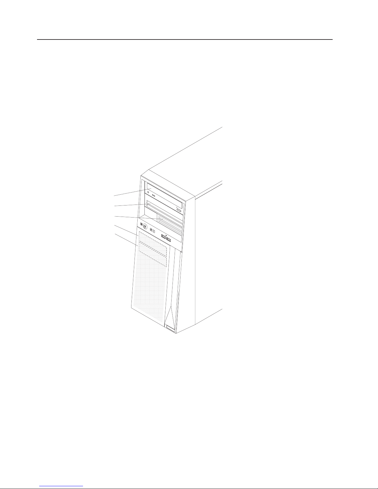
Front view
The following illustration shows the controls, LEDs, and connectors on the front of
the server.
CD or DVD drive
activity LED
(Optional) Diskette drive
activity LED
Power-on LED
Power-control
button
CD or DVD eject button
Press this button to release a CD or DVD from the CD or DVD drive.
(Optional) Diskette-eject button
Press this button to release a diskette from the diskette drive.
Hard disk drive activity LED
When this LED is flashing, it indicates that a hard disk drive is in use.
USB connectors
Connect a USB device to these connectors.
System-error LED
When this LED is lit, it indicates that a system error has occurred. An LED
on the system board might also be lit to help isolate the error. See
Chapter 5, “Solving problems,” on page 39 for additional information.
Detailed troubleshooting information is in the Problem Determination and
Service Guide on the IBM System x Documentation CD.
CD or DVD eject
button
(Optional) Diskette-eject
button
Hard disk drive
activity LED
USB (2)
System error LED
Power-control button
© Copyright IBM Corp. 2007 29
Press this button to turn the server on and off manually. A
power-control-button shield comes with the server.
Page 44

Power-on LED
When this LED is lit, it indicates that the server is turned on. When this LED
is off, it indicates that ac power is not present, or the power supply or the
LED itself has failed.
Note: If this LED is off, it does not mean that there is no electrical power in
the server. The LED might be burned out. To remove all electrical
power from the server, you must disconnect the power cord from the
electrical outlet.
(Optional)
Diskette drive activity LED
When this LED is lit, it indicates that the diskette drive is in use.
CD or DVD drive activity LED
When this LED is lit, it indicates that the CD or DVD drive is in use.
30 System x3105 Type 4347: Installation Guide
Page 45
Rear view
The following illustration shows the connectors on the rear of the server.
Power-supply
voltage switch
115
Power cord connector
115
Power-supply error LED
Power-supply voltage switch
AC power LED
Video connector
Parallel connector
Serial connector
Ethernet link status LED
USB 4 connector
Ethernet
USB 3 connector
Ethernet activity LED
USB 2 connector
USB 1 connector
Power-cord connector
Connect the power cord to this connector.
Power-supply error LED
When this amber LED is lit, it indicates that a power-supply error has
occurred.
Power supply voltage switch
Use this switch to change the system ac power-supply input voltage for
your geographic location. Set the input voltage to the correct level (115 volts
ac or 230 volts ac) based on your power requirements before you turn on
the server.
AC power LED
When this green LED is lit, it indicates that the server is connected to an ac
power source.
Video connector
Connect a monitor to this connector.
Parallel connector
Connect a parallel device to this connector.
Chapter 3. Server controls, LEDs, and power 31
Page 46

Serial connector
Connect a 9-pin serial device to this connector.
Ethernet link status LED
This LED is on the Ethernet connector on the rear of the server. When this
LED is lit, it indicates that there is an active connection on the Ethernet
port.
USB connectors
Connect USB devices to these connectors.
Ethernet connector
Use this connector to connect the server to a network.
Ethernet transmit/receive activity LED
This LED is on the Ethernet connector on the rear of the server. When this
LED is lit, it indicates that there is activity between the server and the
network.
Server power features
When the server is connected to an ac power source but is not turned on, the
operating system does not run, and all core logic, except for the service processor,
is shut down; however, the server can respond to requests from the service
processor, such as a remote request to turn on the server. When the power LED is
flashing it indicates that the server is connected to an ac power source but is not
turned on.
Setting the power supply voltage
Before you turn on the server, make sure that you do the following:
1. Remove the label or tape (if present) from the ac power supply voltage switch
on the rear of the server.
2. Set the power-supply voltage to the level required for your geography (115 volts
ac or 230 volts ac).
Turning on the server
Approximately 20 seconds after the server is connected to ac power, the
power-control button becomes active, and one or more fans might start running to
provide cooling while the server is connected to power. Yo u can turn on the server
and start the operating system by pressing the power-control button.
The server can also be turned on in any of the following ways:
v If a power failure occurs while the server is turned on, the server will restart
automatically when power is restored.
v If your operating system supports the Wake on LAN feature, the Wake on LAN
feature can turn on the server.
When 4 GB or more of memory (physical or logical) is installed, some
Note:
memory is reserved for various system resources and is unavailable to the
operating system. The amount of memory that is reserved for system
resources depends on the operating system, the configuration of the server,
and the configured PCI or PCI Express options.
32 System x3105 Type 4347: Installation Guide
Page 47

Turning off the server
When you turn off the server and leave it connected to ac power, the server can
respond to requests from the service processor, such as a remote request to turn
on the server. While the server remains connected to ac power, one or more fans
might continue to run. To remove all power from the server, you must disconnect it
from the power source.
Some operating systems require an orderly shutdown before you turn off the server.
See your operating-system documentation for information about shutting down the
operating system.
Chapter 3. Server controls, LEDs, and power 33
Page 48

Statement 5:
CAUTION:
The power control button on the device and the power switch on the power
supply do not turn off the electrical current supplied to the device. The device
also might have more than one power cord. To remove all electrical current
from the device, ensure that all power cords are disconnected from the power
source.
2
1
The server can be turned off in any of the following ways:
v Yo u can turn off the server from the operating system, if your operating system
supports this feature. After an orderly shutdown of the operating system, the
server will be turned off automatically.
v Yo u can press the power-control button to start an orderly shutdown of the
operating system and turn off the server, if your operating system supports this
feature.
v If the operating system stops functioning, you can press and hold the
power-control button for more than 4 seconds to turn off the server.
v If the Wake on LAN feature turned on the server, the Wake on LAN feature can
turn off the server.
v The server can turn itself off as an automatic response to a critical system
failure.
v Yo u can turn off the server through a request from the service processor.
34 System x3105 Type 4347: Installation Guide
Page 49

Chapter 4. Configuring the server
The ServerGuide Setup and Installation CD provides software setup tools and
installation tools that are specifically designed for your IBM server. Use this CD
during the initial installation of the server to configure basic hardware features and
to simplify your operating system installation.
In addition to the ServerGuide Setup and Installation CD, you can use the following
configuration programs to customize the server hardware:
v Configuration/Setup Utility program
v Boot Menu program
v Broadcom NetXtreme Gigabit Ethernet Boot Agent
v Ethernet controller configuration
more information about these programs, see “Configuring the server” in the
For
User’s Guide on the IBM System x Documentation CD.
Using the ServerGuide Setup and Installation CD
The ServerGuide Setup and Installation CD provides programs to detect the server
model and installed optional hardware devices, configure the server hardware,
provide device drivers, and help you install the operating system. For information
about the supported operating-system versions, see the label on the CD. If the
ServerGuide Setup and Installation CD did not come with the server, you can
download the latest version from http://www.ibm.com/pc/qtechinfo/MIGR4ZKPPT.html.
To start the ServerGuide Setup and Installation CD, complete the following steps:
1. Insert the CD, and restart the server. If the CD does not start, see “ServerGuide
problems” on page 59
2. Follow the instructions that appear on the screen to:
a. Select your language.
b. Select your keyboard layout and country.
c. View the overview to learn about ServerGuide features.
d. View the readme file to review installation tips about your operating system
and adapter.
e. Start the setup and hardware configuration programs.
f. Start the operating system installation. You will need your operating-system
CD.
Using the Configuration/Setup Utility program
The Configuration/Setup Utility program is part of the BIOS code. You can use it to:
v Change interrupt request (IRQ) settings
v Change the startup drive sequence
v Configure serial-port assignments
v Enable USB keyboard and mouse support
v Resolve configuration conflicts
v Set the date and time
v Set passwords and security settings
© Copyright IBM Corp. 2007 35
Page 50

To start the Configuration/Setup Utility program, complete the following steps:
1. Turn on the server.
2. When the message Press F1 for Configuration/Setup is displayed, press F1.
If an administrator password has been set, you must type the administrator
password to access the full Configuration/Setup Utility menu.
3. Follow the instructions on the screen.
the User’s Guide on the IBM System x Documentation CD for more detailed
See
information about the Configuration/Setup Utility program.
Using the Boot Menu program
The Boot Menu program is a built-in, menu-driven configuration program that you
can use to temporarily redefine the first startup device without changing settings in
the Configuration/Setup Utility program.
To use the Boot Menu program, complete the following steps:
1. Turn off the server.
2. Restart the server.
3. Press F12.
4. Select the startup device.
next time the server is started, it returns to the startup sequence that is set in
The
the Configuration/Setup Utility program.
Enabling the Broadcom NetXtreme Gigabit Ethernet Boot Agent
The Broadcom NetXtreme Gigabit Ethernet Boot Agent is part of the BIOS. Yo u can
use it to configure the network as a startable device, and you can customize where
the network startup option occurs in the startup sequence. Enable and disable the
Broadcom NetXtreme Gigabit Ethernet Boot Agent from the Configuration/Setup
Utility program.
To enable the Broadcom NetXtreme Gigabit Ethernet Boot Agent, complete the
following steps:
1. Turn on the server.
2. When the prompt Press F1 for Configuration/Setup is displayed during
startup, press F1.
3. From the Configuration/Setup Utility main menu, select Devices and I/O Ports
and press Enter.
4. Select System Board Ethernet PXE/DHCP and press the Right Arrow (→) key
to set it to Enabled.
5. Select Save Settings and press Enter.
Configuring the Broadcom NetXtreme Gigabit Ethernet controller
The Ethernet controller is integrated on the system board. It provides an interface
for connecting to a 10 Mbps, 100 Mbps, or 1 Gbps network and provides full duplex
(FDX) capability, which enables simultaneous transmission and reception of data on
the network. If the Ethernet port in the server supports auto-negotiation, the
controller detects the data-transfer rate (10BASE-T, 100BASE-TX, or 1000BASE-T)
and duplex mode (full-duplex or half-duplex) of the network and automatically
operates at that rate and mode.
36 System x3105 Type 4347: Installation Guide
Page 51

You do not have to set any jumpers or configure the controllers. However, you must
install a device driver to enable the operating system to address the controllers. For
device drivers and information about configuring the Ethernet controllers, see the
Broadcom NetXtreme Gigabit Ethernet Software CD that comes with the server. To
find updated information about configuring the controllers, complete the following
steps.
Note: Changes are made periodically to the IBM Web site. The actual procedure
might vary slightly from what is described in this document.
1. Go to http://www.ibm.com/servers/eserver/support/xseries/index.html.
2. From the Hardware list, select System x3105 and click Go.
3. Click the Install and use tab.
4. Click Product documentation.
Chapter 4. Configuring the server 37
Page 52

38 System x3105 Type 4347: Installation Guide
Page 53

Chapter 5. Solving problems
This chapter provides basic troubleshooting information to help you solve some
common problems that might occur while you are setting up the server.
If you cannot diagnose and correct a problem by using the information in this
chapter, see Appendix A, “Getting help and technical assistance,” on page 65, the
Problem Determination and Service Guide on the IBM® System x Documentation
CD, and the “Server Support” flowchart in the front of this document.
Diagnostic tools overview
The following tools are available to help you diagnose and solve hardware-related
problems:
v POST beep codes
The power-on self-test (POST) codes indicate the detection of a problem.
– One beep indicates successful completion of POST, with no errors.
– More than one beep indicates that POST detected a problem. Error messages
also appear during startup if POST detects a hardware-configuration problem.
See “POST beep codes” in the Problem Determination and Service Guide on
the IBM System x Documentation CD for more information.
Troubleshooting tables
v
These tables list problem symptoms and actions to correct the problems. See
“Troubleshooting tables” on page 50 for more information.
v Diagnostic programs and error messages
The system diagnostic programs are provided on the IBM Enhanced Diagnostics
CD. These programs test the major components of the server. See “POST beep
codes” on page 40 and the Problem Determination and Service Guide on the
IBM System x Documentation CD for more information.
v System-board error LEDs
When the system-error LED on the front of the server is lit, an LED on the
system board might also be lit to help isolate an erro. See “System-board error
LEDs” on page 61 for more information.
© Copyright IBM Corp. 2007 39
Page 54

POST beep codes
POST emits one beep to signal successful completion. If POST detects a problem
during startup, other beep codes might occur. Use the following beep code
descriptions to help diagnose and solve problems that are detected during startup.
Note: See the Problem Determination and Service Guide on the IBM System x
Documentation CD for more information about the POST beep codes.
Repeating
long beeps
A memory error has occurred. Make sure that all DIMMs are correctly
installed. For additional information, see beep code 3-3-3 in the Problem
Determination and Service Guide on the IBM System x Documentation CD.
Other beep codes
See the Problem Determination and Service Guide on the IBM System x
Documentation CD for information about other beep codes.
POST error codes
The following table provides an abbreviated list of the error codes that might appear
during POST. See the Problem Determination and Service Guide on the IBM
System x Documentation CD for more information about the POST error codes. To
check for updated technical information, go to http://www.ibm.com/servers/eserver/
support/xseries/index.html, select System x3105, and click Go; then, click the
Install and use tab and click Product documentation.
v Follow the suggested actions in the order in which they are listed in the Action column until the problem
is solved.
v See the parts listing in the Problem Determination and Service Guide to determine which components are
customer replaceable units (CRU) and which components are field replaceable units (FRU).
v If an action step is preceded by “(Trained service technician only),” that step must be performed only by a
trained service technician.
Error code Description Action
062 The server failed to start on three
consecutive boots using the default
configuration.
101, 102 A tick timer internal interrupt, internal timer
channel 2 error occurred.
106 A diskette controller failure occurred.
1. Update the system firmware to the latest level.
2. (Trained service technician only) Replace the
system board.
(Trained service technician only) Replace the system
board.
1. Make sure that the Configuration/Setup Utility
program correctly reflects the type of diskette
drive.
2. Reseat the following components:
a. Diskette drive cable
b. Diskette drive
3.
Replace the following components one at a time
in the order shown, restarting the server each
time:
a. Diskette drive cable
b. Diskette drive
c. (Trained service technician only) System
board
40 System x3105 Type 4347: Installation Guide
Page 55

v Follow the suggested actions in the order in which they are listed in the Action column until the problem
is solved.
v See the parts listing in the Problem Determination and Service Guide to determine which components are
customer replaceable units (CRU) and which components are field replaceable units (FRU).
v If an action step is preceded by “(Trained service technician only),” that step must be performed only by a
trained service technician.
Error code Description Action
151 A real-time clock error occurred.
1. Reseat the battery.
2. Replace the following components one at a time,
in the order shown, restarting the server each
time:
a. Battery
b. (Trained service technician only) System
board
161 A real-time clock battery error occurred.
1. Reseat the battery.
2. Replace the following components one at a time,
in the order shown, restarting the server each
time:
a. Battery
b. (Trained service technician only) System
board
162 Device configuration error occurred.
1. Run the Configuration/Setup Utility program,
select Load Default Settings, and save the
settings.
2. Reseat the following components:
a. Battery
b. Failing device (if the device is a FRU, the
device must be replaced by a trained service
technician only)
Replace the following components one at a time,
3.
in the order shown, restarting the server each
time:
a. Battery
b. Failing device (if the device is a FRU, the
device must be replaced by a trained service
technician only)
c. (Trained service technician only) System
board
163 A real-time clock error occurred.
1. Run the Configuration/Setup Utility program,
select Load Default Settings, make sure that the
date and time are correct, and save the settings.
2. Reseat the battery.
3. Replace the following components one at a time,
in the order shown, restarting the server each
time:
a. Battery
b. (Trained service technician only) System
board
Chapter 5. Solving problems 41
Page 56

v Follow the suggested actions in the order in which they are listed in the Action column until the problem
is solved.
v See the parts listing in the Problem Determination and Service Guide to determine which components are
customer replaceable units (CRU) and which components are field replaceable units (FRU).
v If an action step is preceded by “(Trained service technician only),” that step must be performed only by a
trained service technician.
Error code Description Action
164 Memory configuration changed.
1. Run the configuration/Setup Utility program,
select Load Default Settings, and save the
settings.
2. Reseat the DIMMs.
3. Replace the following components one at a time,
in the order shown, restarting the server each
time:
a. Battery
b. (Trained service technician only) System
board
184 The power-on password is damaged.
1. Run the Configuration/Setup Utility program,
select Load Default Settings, and save the
settings.
2. Reseat the battery.
3. Replace the following components one at a time,
in the order shown, restarting the server each
time:
a. Battery
b. (Trained service technician only) System
board
187 VPD serial number is not set.
1. Run the Configuration/Setup Utility program, set
the serial number, and save the configuration.
2. (Trained service technician only) Replace the
system board.
189 An attempt was made to access the server
with an incorrect password.
Restart the server and enter the administrator
password; then, run the Configuration/Setup Utility
program and change the power-on password.
289 A DIMM has been disabled by the user or
by the system.
1. If the DIMM was disabled by the user, run the
Configuration/Setup Utility program and enable
the DIMM (see “Using the Configuration/Setup
Utility program” on page 35).
2. Make sure that the DIMM is installed correctly.
3. Reseat the DIMM.
4. Replace the DIMM.
42 System x3105 Type 4347: Installation Guide
Page 57

v Follow the suggested actions in the order in which they are listed in the Action column until the problem
is solved.
v See the parts listing in the Problem Determination and Service Guide to determine which components are
customer replaceable units (CRU) and which components are field replaceable units (FRU).
v If an action step is preceded by “(Trained service technician only),” that step must be performed only by a
trained service technician.
Error code Description Action
301 A keyboard or keyboard controller error
occurred.
1. If you have installed a USB keyboard, run the
Configuration/Setup Utility program and enable
keyboardless operation to prevent this error
message from being displayed during startup.
2. Reseat the keyboard cable.
3. Replace the following components one at a time,
in the order shown, restarting the server each
time:
a. Keyboard
b. (Trained service technician only) System
board
303 A keyboard controller error occurred.
1. Reseat the keyboard cable.
2. Replace the following components one at a time,
in the order shown, restarting the server each
time:
a. Keyboard
b. (Trained service technician only) System
board
602 An invalid diskette boot record error
occurred
1. Reseat the diskette drive cable.
2. Replace the following components one at a time,
in the order shown, restarting the server each
time:
a. Diskette drive cable
b. Diskette drive
c. (Trained service technician only) System
board
604 An error occurred during a diskette drive
test.
1. Make sure that the Configuration/Setup Utility
program correctly reflects the type of diskette
drive that is installed.
2. Reseat the diskette drive cable.
3. Replace the following components one at a time,
in the order shown, restarting the server each
time:
a. Diskette drive cable
b. Diskette drive
c. (Trained service technician only) System
board
Chapter 5. Solving problems 43
Page 58

v Follow the suggested actions in the order in which they are listed in the Action column until the problem
is solved.
v See the parts listing in the Problem Determination and Service Guide to determine which components are
customer replaceable units (CRU) and which components are field replaceable units (FRU).
v If an action step is preceded by “(Trained service technician only),” that step must be performed only by a
trained service technician.
Error code Description Action
662 A diskette drive configuration error occurred.
1. Make sure that the Configuration/Setup Utility
program correctly reflects the type of diskette
drive.
2. Reseat the following components:
a. Diskette drive cable
b. Diskette drive
Replace the following components one at a time
3.
in the order shown, restarting the server each
time:
a. Diskette drive cable
b. Diskette drive
c. (Trained service technician only) System
board
962 A parallel port configuration error occurred
1. If you changed an optional hardware device,
make sure that the parallel port setting is correct
in the Configuration/Setup Utility program. If the
setting is not correct, change it and save the
settings.
2. (Trained service technician only) Replace the
system board.
1162 The serial port configuration conflicts with
another device in the system.
1. Make sure that the interrupt request (IRQ) and
I/O port assignments that are needed by the
serial port are available.
2. If all interrupts are being used by adapters,
remove an adapter to make an interrupt available
to the serial port, or force other adapters to share
an interrupt.
3. Make sure that the serial port setting is correct in
the Configuration/Setup Utility program. If the
setting is not correct, change it and save the
settings.
4. (Trained service technician only) Replace the
system board.
1762 A fixed disk configuration error occurred.
1. Run the Configuration/Setup Utility program and
load the defaults.
2. Reseat the following components:
a. Hard disk drive cables
b. Hard disk drive
c. (Trained service technician only) System
board
Replace the components listed in step 2 one at a
3.
time, in the order shown, restarting the server
each time.
44 System x3105 Type 4347: Installation Guide
Page 59

v Follow the suggested actions in the order in which they are listed in the Action column until the problem
is solved.
v See the parts listing in the Problem Determination and Service Guide to determine which components are
customer replaceable units (CRU) and which components are field replaceable units (FRU).
v If an action step is preceded by “(Trained service technician only),” that step must be performed only by a
trained service technician.
Error code Description Action
178x A fixed disk error occurred.
1. Reseat the hard disk drive cable.
2. Replace the hard disk drive cable.
3. Run the hard disk drive diagnostic tests (see the
Problem Determination and Service Guide for
information about running the diagnostic tests).
4. Replace the following components one at a time,
in the order shown, restarting the server each
time.
a. Hard disk drive
b. (Trained service technician only) System
board
1801 A PCI adapter has requested memory
resources that are not available.
1. Make sure that no devices have been disabled in
the Configuration/Setup Utility program.
2. Change the order of the adapters in the PCI or
PCI Express slots. Make sure that the startup
(boot) device is positioned early in the scanning
order. (For information about the scanning order,
see the User’s Guide on the IBM System x
Documentation CD).
3. Make sure that the settings for the adapter and all
other adapters in the Configuration/Setup Utility
program are correct. If the memory resource
settings are not correct, change them.
4. If all memory resources are being used, remove
an adapter to make memory available to the
adapter. Disabling the BIOS on the adapter might
correct the error. See the documentation that
comes with the adapter.
1802 No more I/O space is available for a PCI or
PCI Express adapter.
1. Make sure that the settings for the adapter and all
other adapters in the Configuration/Setup Utility
program are correct.
2. If the error code indicates a particular PCI or PCI
Express slot or device, remove that device.
3. Reseat each adapter.
4. Replace the following components one at a time,
in the order shown, restarting the server each
time:
a. Adapter
b. (Trained service technician only) System
board
Chapter 5. Solving problems 45
Page 60

v Follow the suggested actions in the order in which they are listed in the Action column until the problem
is solved.
v See the parts listing in the Problem Determination and Service Guide to determine which components are
customer replaceable units (CRU) and which components are field replaceable units (FRU).
v If an action step is preceded by “(Trained service technician only),” that step must be performed only by a
trained service technician.
Error code Description Action
1803 No more memory (above 1 MB for a PCI or
PCI Express adapter).
1. Make sure that the settings for the adapter and all
other adapters in the Configuration/Setup Utility
program are correct.
2. If the error code indicates a particular PCI or PCI
Express slot or device, remove that device.
3. Reseat each adapter.
4. Replace the following components one at a time,
in the order shown, restarting the server each
time:
a. Adapter
b. (Trained service technician only) System
board
1804 No more memory (below 1 MB for a PCI or
PCI Express adapter).
1. Make sure that the settings for the adapter and all
other adapters in the Configuration/Setup Utility
program are correct.
2. If the error code indicates a particular PCI or PCI
Express slot or device, remove that device.
3. Reseat each adapter.
4. Replace the following components one at a time,
in the order shown, restarting the server each
time:
a. Adapter
b. (Trained service technician only) System
board
1805 PCI option ROM checksum error occurred.
1. Remove the failing adapter.
2. Reseat each adapter.
3. Replace the following components one at a time,
in the order shown, restarting the sever each
time:
a. Adapter
b. (Trained service technician only) System
board
1806 PCI built-in self-test failure occurred.
1. Make sure that the settings for the adapter and all
other adapters in the Configuration/Setup Utility
program are correct.
2. If the error code indicates a particular PCI or PCI
Express slot or device, remove that device.
3. Reseat each adapter.
4. Replace the following components one at a time,
in the order shown, restarting the server each
time:
a. Adapter
b. (Trained service technician only) System
board
46 System x3105 Type 4347: Installation Guide
Page 61

v Follow the suggested actions in the order in which they are listed in the Action column until the problem
is solved.
v See the parts listing in the Problem Determination and Service Guide to determine which components are
customer replaceable units (CRU) and which components are field replaceable units (FRU).
v If an action step is preceded by “(Trained service technician only),” that step must be performed only by a
trained service technician.
Error code Description Action
1807, 1808 General PCI error occurred.
1. Make sure that no devices have been disabled in
the Configuration/Setup Utility program.
2. Reseat the failing adapter.
Note: If an error LED is lit on an adapter, reseat
that adapter first; if no LEDs are lit, reseat each
adapter one at a time, restarting the server each
time to isolate the failing adapter.
3. Replace the following components one at a time,
in the order shown, restarting the server each
time:
a. Adapter
b. (Trained service technician only) System
board
1962 A hard disk drive does not contain a valid
boot sector.
1. Make sure that a bootable operating system is
installed.
2. Run the hard disk drive diagnostic tests (see the
Problem Determination and Service Guide for
information about running the diagnostic tests).
3. Reseat the hard disk drive cable.
4. Replace the following components one at a time,
in the order shown, restarting the server each
time:
a. Hard disk drive cable
b. Hard disk drive
c. (Trained service technician only) System
board
5962 IDE, CD or DVD drive configuration error
occurred.
1. Run the Configuration/Setup Utility program and
load the default settings.
2. Reseat the CD or DVD drive cable.
3. Replace the following components one at a time,
in the order shown, restarting the server each
time.
a. CD or DVD drive cable
b. CD or DVD drive
c. (Trained service technician only) System
board
8603 A pointing-device error occurred.
1. Reseat the pointing device cable.
2. Replace the following components one at a time,
in the order shown, restarting the server each
time:
a. Pointing device
b. (Trained service technician only) System
board
Chapter 5. Solving problems 47
Page 62

v Follow the suggested actions in the order in which they are listed in the Action column until the problem
is solved.
v See the parts listing in the Problem Determination and Service Guide to determine which components are
customer replaceable units (CRU) and which components are field replaceable units (FRU).
v If an action step is preceded by “(Trained service technician only),” that step must be performed only by a
trained service technician.
Error code Description Action
00012000 A processor machine check error occurred.
1. (Trained service technician only) Reseat the
microprocessor.
2. Replace the following components one at a time,
in the order shown, restarting the server each
time:
a. (Trained service technician only)
Microprocessor
b. (Trained service technician only) System
board
00019701 Processor failed built-in self test (BIST).
1. (Trained service technician only) Reseat the
microprocessor.
2. Replace the following components one at a time,
in the order shown, restarting the server each
time:
a. (Trained service technician only)
Microprocessor
b. (Trained service technician only) System
board
01298101 A bad update data for processor error
occurred.
1. Update the BIOS code (see ″Updating the
firmware″ in the Problem Determination and
Service Guide).
2. (Trained service technician only) Reseat the
microprocessor.
3. (Trained service technician only) Replace the
microprocessor.
I9990301 A hard disk drive boot sector error occurred.
1. Reseat the hard disk drive cable.
2. Reseat the hard disk drive.
3. Replace the following components one at a time,
in the order shown, restarting the server each
time:
a. Hard disk drive cable
b. Hard disk drive
c. (Trained service technician only) System
board
48 System x3105 Type 4347: Installation Guide
Page 63

v Follow the suggested actions in the order in which they are listed in the Action column until the problem
is solved.
v See the parts listing in the Problem Determination and Service Guide to determine which components are
customer replaceable units (CRU) and which components are field replaceable units (FRU).
v If an action step is preceded by “(Trained service technician only),” that step must be performed only by a
trained service technician.
Error code Description Action
I9990305 An operating system was not found.
1. Make sure that a bootable operating system is
installed.
2. Run the hard disk drive diagnostic tests (see the
Problem Determination and Service Guide for
information about running the diagnostic tests).
3. Reseat the following components:
a. Hard disk drive cable
b. CD or DVD drive and cables drive.
c. (Trained service technician only) System
board
Replace the components listed in step 3 one at a
4.
time in the order shown, restarting the server
each time.
19990650 The ac power has been restored.
1. Reseat the power cord.
2. Check for the interruption of external power
source.
3. Replace the power cord.
Chapter 5. Solving problems 49
Page 64

Troubleshooting tables
Use the troubleshooting tables to find solutions to problems that have identifiable
symptoms. See the Problem Determination and Service Guide on the IBM System x
Documentation CD for more detailed troubleshooting information. If you cannot find
a problem in these tables, run the diagnostic programs (see “Running the diagnostic
programs” in the Problem Determination and Service Guide).
If you have just added new software or a new optional device and the server is not
working, complete the following steps before you use the troubleshooting tables:
1. Remove the software or device that you just added.
2. Run the diagnostic tests to determine whether the server is running correctly.
3. Reinstall the new software or new device.
CD or DVD drive problems
v Follow the suggested actions in the order in which they are listed in the Action column until the problem
is solved.
v See the parts listing in the Problem Determination and Service Guide to determine which components are
customer replaceable units (CRU) and which components are field replaceable units (FRU).
v If an action step is preceded by “(Trained service technician only)” , that step must be performed only by
a trained service technician.
Symptom Action
CD or DVD drive is not
recognized.
A CD or DVD is not working
correctly.
The CD or DVD drive tray is not
working.
1. Make sure that:
v The IDE channel to which the CD or DVD drive is attached (primary or
secondary) is enabled in the Configuration/Setup Utility program.
v All cables and jumpers are installed correctly.
v The correct device driver is installed for the CD or DVD drive.
Run the CD or DVD drive diagnostic programs.
2.
3. Reseat the following components:
a. CD or DVD drive
b. CD or DVD drive cable
c. (Trained service technician only) System board
Replace the components listed in step 3 one at a time, in the order shown,
4.
restarting the server each time.
1. Clean the CD or DVD.
2. Run the CD or DVD drive diagnostic programs.
3. Reseat the CD or DVD drive cable.
4. Reseat the CD or DVD drive.
5. Replace the CD or DVD drive
1. Make sure that the server is turned on.
2. Insert the end of a straightened paper clip into the manual tray-release
opening.
3. Reseat the CD or DVD drive.
4. Replace the CD or DVD drive.
50 System x3105 Type 4347: Installation Guide
Page 65

Diskette drive problems
v Follow the suggested actions in the order in which they are listed in the Action column until the problem
is solved.
v See the parts listing in the Problem Determination and Service Guide to determine which components are
customer replaceable units (CRU) and which components are field replaceable units (FRU).
v If an action step is preceded by “(Trained service technician only)”, that step must be performed only by a
trained service technician.
Symptom Action
The diskette drive activity LED
stays lit, or the server bypasses
the diskette drive.
1. If there is a diskette in the drive, make sure that:
v The diskette drive is enabled in the Configuration/Setup Utility program.
v The diskette is good and not damaged. (Try another diskette if you have
one.)
v The diskette is inserted correctly in the drive.
v The diskette contains the necessary files to start the server.
v The software is working correctly.
v The cable is connected correctly (in the correct orientation).
To prevent diskette drive read/write errors, make sure that the distance
2.
between monitors and diskette drives is at least 76 mm (3 in.).
3. Run the diskette drive diagnostic test.
4. Reseat the following components:
a. Diskette drive cable
b. Diskette drive
c. (Trained service technician only) System board
Replace the components listed in step 3 one at a time, in the order shown,
5.
restarting the server each time.
General problems
v Follow the suggested actions in the order in which they are listed in the Action column until the problem
is solved.
v See the parts listing in the Problem Determination and Service Guide to determine which components are
customer replaceable units (CRU) and which components are field replaceable units (FRU).
v If an action step is preceded by “(Trained service technician only)”, that step must be performed only by a
trained service technician.
Symptom Action
A cover lock is broken, an
indicator LED is not working, or
a similar problem has occurred.
If the part is a CRU, replace it. If the part is a FRU, the part must be replaced by a
trained service technician.
Chapter 5. Solving problems 51
Page 66

Hard disk drive problems
v Follow the suggested actions in the order in which they are listed in the Action column until the problem
is solved.
v See the parts listing in the Problem Determination and Service Guide to determine which components are
customer replaceable units (CRU) and which components are field replaceable units (FRU).
v If an action step is preceded by “(Trained service technician only)”, that step must be performed only by a
trained service technician.
Symptom Action
Not all drives are recognized by
the hard disk drive diagnostic
test (the Fixed Disk test).
The server stops responding
during the hard disk drive
diagnostic test.
A hard disk drive was not
detected while the operating
Remove the drive that is indicated by the diagnostic tests; then, run the hard disk
drive diagnostic test again. If the remaining drives are recognized, replace the drive
that you removed with a new one.
Remove the hard disk drive that was being tested when the server stopped
responding, and run the diagnostic test again. If the hard disk drive diagnostic test
runs successfully, replace the drive that you removed with a new one.
Reseat all hard disk drives and cables; then, run the hard disk drive diagnostic
tests again.
system was being started.
Intermittent problems
v Follow the suggested actions in the order in which they are listed in the Action column until the problem
is solved.
v See the parts listing in the Problem Determination and Service Guide to determine which components are
customer replaceable units (CRU) and which components are field replaceable units (FRU).
v If an action step is preceded by “(Trained service technician only)”, that step must be performed only by a
trained service technician.
Symptom Action
A problem occurs only
occasionally and is difficult to
detect.
Make sure that:
v All cables and cords are connected securely to the rear of the server and
attached devices.
v When the server is turned on, air is flowing from the fan grille. If there is no
airflow, the fan is not working. This can cause the server to overheat and shut
down.
v Make sure that the SCSI bus and devices are configured correctly and that the
last external device in each SCSI chain is terminated correctly.
52 System x3105 Type 4347: Installation Guide
Page 67

Keyboard, mouse, or pointing-device problems
v Follow the suggested actions in the order in which they are listed in the Action column until the problem
is solved.
v See the parts listing in the Problem Determination and Service Guide to determine which components are
customer replaceable units (CRU) and which components are field replaceable units (FRU).
v If an action step is preceded by “(Trained service technician only)”, that step must be performed only by a
trained service technician.
Symptom Action
All or some keys on the
keyboard do not work.
The mouse or pointing device
does not work.
1. Make sure that:
v The keyboard cable is securely connected to the server.
v The server and the monitor are turned on.
Run the Configuration/Setup Utility program and enable keyboardless operation
2.
to prevent the 301 POST error message from being displayed during startup.
3. If you are using a USB keyboard and it is connected to a USB hub, disconnect
the keyboard from the hub and connect it directly to the server.
4. Replace the following components one at a time, in the order shown, restarting
the server each time:
a. Keyboard
b. (Trained service technician only) System board
1. Make sure that:
v The mouse or pointing-device cable is securely connected to the server.
v The mouse or pointing device drivers are installed correctly.
v The server and the monitor are turned on.
v The keyboardless operation and mouse options are enabled in the
Configuration/Setup Utility program.
If you are using a USB mouse or pointing device and it is connected to a USB
2.
hub, disconnect the mouse or pointing device from the hub and connect it
directly to the server.
3. Replace the following components one at a time, in the order shown, restarting
the server each time:
a. Mouse or pointing device
b. (Trained service technician only) System board
Chapter 5. Solving problems 53
Page 68

Memory problems
v Follow the suggested actions in the order in which they are listed in the Action column until the problem
is solved.
v See the parts listing in the Problem Determination and Service Guide to determine which components are
customer replaceable units (CRU) and which components are field replaceable units (FRU).
v If an action step is preceded by “(Trained service technician only)”, that step must be performed only by a
trained service technician.
Symptom Action
The amount of system memory
displayed is less than the
amount of installed physical
memory.
1. Make sure that:
v No error LEDs are lit on the system board.
v The memory modules are seated corrected.
v You have installed the correct type of memory.
v If you changed the memory, you updated the memory configuration in the
Configuration/Setup Utility program.
v All banks of memory are enabled. The server might have automatically
disabled a memory bank when it detected a problem, or a memory bank
might have been manually disabled.
Check the POST error log for error message 289:
2.
v If the DIMM was disabled by a systems-management interrupt (SMI), replace
the DIMM.
v If the DIMM was disabled by the user or by POST, run the
Configuration/Setup Utility program and enable the DIMM.
Run memory diagnostics (see ″Running the programs″ in the Problem
3.
Determination and Service Guide.
4. Make sure that there is no memory mismatch when the server is over the
minimum memory configuration (one 512 MB DIMM: see the information about
the minimum required configuration on page 11).
5. Reseat the following components:
a. DIMM
b. (Trained service technician only) System board
Replace the components listed in step 5 one at a time, in the order shown,
6.
restarting the server each time.
Microprocessor problems
v Follow the suggested actions in the order in which they are listed in the Action column until the problem
is solved.
v See the parts listing in the Problem Determination and Service Guide to determine which components are
customer replaceable units (CRU) and which components are field replaceable units (FRU).
v If an action step is preceded by “(Trained service technicain only)”, that step must be performed only by a
trained service technician.
Symptom Action
The server emits a continuous
beep during POST, indicating
that the startup (boot)
microprocessor is not working
correctly.
54 System x3105 Type 4347: Installation Guide
1. (Trained service technician only) Make sure that the microprocessor is seated
2. (Trained service technician only) Replace the microprocessor.
correctly.
Page 69
Monitor or video problems
Some IBM monitors have their own self-tests. If you suspect a problem with your
monitor, see the documentation that comes with the monitor for instructions for
testing and adjusting the monitor.
v Follow the suggested actions in the order in which they are listed in the Action column until the problem
is solved.
v See the parts listing in the Problem Determination and Service Guide to determine which components are
customer replaceable units (CRU) and which components are field replaceable units (FRU).
v If an action step is preceded by “(Trained service technician only)”, that step must be performed only by a
trained service technician.
Symptom Action
Testing the monitor
The screen is blank.
Only the cursor appears. See “Solving undetermined problems” in the Problem Determination and Service
The monitor works when you
turn on the server, but the
screen goes blank when you
start some application
programs.
1. Make sure that the monitor cables are firmly connected.
2. Try using a different monitor on the server, or try using the monitor that is being
tested on a different server.
3. Run the diagnostic programs. If the monitor passes the diagnostic programs,
the problem might be a video device driver.
4. (Trained service technician only) Replace the system board.
1. Make sure that:
v The server is turned on. If there is no power to the server, see ″Power
problems″ in the Problem Determination and Service Guide.
v The monitor cables are connected correctly.
v The monitor is turned on and the brightness and contrast controls are
adjusted correctly.
v Other than the single beep, which indicates successful completion of POST,
no beep codes sound when the server is turned on.
Important:
In some memory configurations, the 3-3-3 beep code might sound
during POST, followed by a blank monitor screen. If this occurs and the Boot
Fail Count option in the Start Options of the Configuration/Setup Utility
program is enabled (its default setting), you must restart the server three times
to reset the configuration settings to the default configuration (the memory
connector or bank of connectors enabled).
2. Make sure that the correct server is controlling the monitor, if applicable.
3. Make sure that damaged BIOS code is not affecting the video; see “Recovering
from a BIOS update failure” on page 62.
4. See ″Solving undetermined problems″ in the Problem Determination and
Service Guide.
Guide.
1. Make sure that:
v The application program is not setting a display mode that is higher than the
capability of the monitor.
v You installed the necessary device drivers for the applications.
Run video diagnostics (see ″Running the diagnostic programs″ in the Problem
2.
Determination and Service Guide.
v If the server passes the video diagnostics the video is good; see ″Solving
undetermined problems″ in the Problem Determination and Service Guide.
v (Trained service technician only ) If the server fails the video diagnostics,
reseat the system board.
v (Trained service technician only) Replace the system board.
Chapter 5. Solving problems 55
Page 70

v Follow the suggested actions in the order in which they are listed in the Action column until the problem
is solved.
v See the parts listing in the Problem Determination and Service Guide to determine which components are
customer replaceable units (CRU) and which components are field replaceable units (FRU).
v If an action step is preceded by “(Trained service technician only)”, that step must be performed only by a
trained service technician.
Symptom Action
The monitor has screen jitters,
or the screen image is wavy,
unreadable, rolling, distorted.
1. If the monitor self-tests show that the monitor is working properly, consider the
location of the monitor. Magnetic fields around other devices (such as
transformers, appliances, fluorescent lights, and other monitors) can cause
screen jitter or wavy, unreadable, rolling, or distorted screen images. If this
happens, turn off the monitor.
Attention: Moving a color monitor while it is turned on might cause screen
discoloration.
Move the device and the monitor at least 305 mm (12 in.) apart, and turn on
the monitor.
Notes:
a. To prevent diskette drive read/write errors, make sure that the distance
between the monitor and any external diskette drive is at least 76 mm (3
in.).
b. Non-IBM monitor cables might cause unpredictable problems.
Reseat the following components:
2.
a. Monitor
b. Video adapter (if one is installed)
c. (Trained service technician only) System board
Replace the components listed in step 2 one at a time, in the order shown,
3.
restarting the server each time.
Wrong characters appear on the
screen.
1. If the wrong language is displayed, update the BIOS code with the correct
language.
2. Reseat the following components:
a. Monitor
b. Video adapter (if one is installed)
c. (Trained service technician only) System board
Replace the components listed in step 2 one at a time, in the order shown,
3.
restarting the server each time.
56 System x3105 Type 4347: Installation Guide
Page 71

Optional-device problems
v Follow the suggested actions in the order in which they are listed in the Action column until the problem
is solved.
v See the parts listing in the Problem Determination and Service Guide to determine which components are
customer replaceable units (CRU) and which components are field replaceable units (FRU).
v If an action step is preceded by “(Trained service technician only)”, that step must be performed only by a
trained service technician.
Symptom Action
An IBM optional device that was
just installed does not work.
An IBM optional device that
used to work does not work
now.
1. Make sure that:
v The device is designed for the server (see http://www.ibm.com/server/
eserver/serverproven/compat/us/).
v You followed the installation instructions that came with the device and the
device is installed correctly.
v You have not loosened any other installed device or cables.
v You updated the configuration information in the Configuration/Setup Utility
program. Whenever memory or any other device is changed, you must
update the configuration.
Reseat the device that you just installed.
2.
3. Replace the device that you just installed.
1. Make sure that all of the cable connections for the device are secure.
2. If the device comes with test instructions, use those instructions to test the
device.
3. If the failing device is a SCSI device, make sure that:
v The cables for all external SCSI options are connected correctly.
v The last device in each SCSI chain, or the end of the SCSI cable, is
terminated correctly.
v Any external SCSI device is turned on. Yo u must turn on an external SCSI
device before turning on the server.
Reseat the failing device.
4.
5. Replace the failing device.
Chapter 5. Solving problems 57
Page 72

Power problems
v Follow the suggested actions in the order in which they are listed in the Action column until the problem
is solved.
v See the parts listing in the Problem Determination and Service Guide to determine which components are
customer replaceable units (CRU) and which components are field replaceable units (FRU).
v If an action step is preceded by “(Trained service technician only),” that step must be performed only by a
trained service technician.
Symptom Action
The power-control button does
not work, and the reset button
does not work (the server does
not start).
Note: The power-control button
will not function until 20
seconds after the server has
been connected to ac power.
The server does not turn off.
The server unexpectedly shuts
down, and the LEDs on the
operator information panel are
not lit.
1. Make sure that the ac power-supply voltage switch on the rear of the server is
set to the correct voltage for your geography.
2. Make sure that the power-control button is working correctly:
a. Disconnect the server power cords.
b. Reconnect the power cords.
c. (Trained service technician) Reseat the operator information panel cables,
and then repeat steps 2a and 2b. If the server starts, reseat the opertor
panel. If the problem remains, replace the operator panel.
Make sure that the reset button is working correctly:
3.
a. Disconnect the server power cords.
b. Reconnect the power cords.
Make sure that:
4.
v The power cords are correctly connected to the server and to a working
electrical outlet.
v The type of memory that is installed is correct.
v The LEDs on the power supply do not indicate a problem.
If you just installed an optional device, remove it, and restart the server. If the
5.
server now starts, you might have installed more devices than the power supply
supports.
6. See ″Solving undetermined problems″ in the Problem Determination and Server
Guide.
1. Determine whether you are using an Advanced Configuration and Power
Interface (ACPI) or non-ACPI operating system. If you are using a non-ACPI
operating system, complete the following steps:
a. Press Ctrl+Alt+Delete.
b. Turn off the server by pressing the power-control button for 5 seconds.
c. Restart the server.
d. If the server fails POST and the power-control button does not work,
disconnect the power cord for 20 seconds; then, reconnect the power cord
and restart the server.
If the problem remains or if you are using an ACPI-aware operating system,
2.
suspect the system board.
See ″Solving undetermined problems″ in the Problem Determination and Server
Guide.
58 System x3105 Type 4347: Installation Guide
Page 73

Serial port problems
v Follow the suggested actions in the order in which they are listed in the Action column until the problem
is solved.
v See the parts listing in the Problem Determination and Service Guide to determine which components are
customer replaceable units (CRU) and which components are field replaceable units (FRU).
v If an action step is preceded by “(Trained service technician only)”, that step must be performed only by a
trained service technician.
Symptom Action
The number of serial ports that
are identified by the operating
system is less than the number
of installed serial ports.
A serial device does not work.
1. Make sure that:
v Each port is assigned a unique address in the Configuration/Setup Utility
program and none of the serial ports is disabled.
v The serial port adapter (if one is present) is seated correctly.
Reseat the serial port adapter.
2.
3. Replace the failing serial port adapter.
1. Make sure that:
v The device is compatible with the server.
v The serial port is enabled and is assigned a unique address.
v The device is connected to the correct connector (see “Connecting the
cables” on page 27).
Reseat the following components:
2.
a. Failing serial device
b. Serial cable
c. (Trained service technician only) System board
Replace the components listed in step 2 one at a time, in the order shown,
3.
restarting the server each time.
ServerGuide problems
v Follow the suggested actions in the order in which they are listed in the Action column until the problem
is solved.
v See the parts listing in the Problem Determination and Service Guide to determine which components are
customer replaceable units (CRU) and which components are field replaceable units (FRU).
v If an action step is preceded by “(Trained service technician only),” that step must be performed only by a
trained service technician.
Symptom Action
The ServerGuide Setup and
Installation CD will not start.
The ServeRAID™ Manager
program cannot view all
installed drives, or the operating
system cannot be installed.
The operating-system
installation program
continuously loops.
1. Make sure that the server supports the ServerGuide program and has a
startable (bootable) CD or DVD drive.
2. If the startup (boot) sequence settings have been changed, make sure that the
CD or DVD drive is first in the startup sequence.
3. If more than one CD or DVD drive is installed, make sure that only one drive is
set as the primary drive. Start the CD from the primary drive.
1. Make sure that the hard disk drive is connected correctly.
2. Make sure that the SAS hard disk drive cables are securely connected.
Make more space available on the hard disk.
Chapter 5. Solving problems 59
Page 74

v Follow the suggested actions in the order in which they are listed in the Action column until the problem
is solved.
v See the parts listing in the Problem Determination and Service Guide to determine which components are
customer replaceable units (CRU) and which components are field replaceable units (FRU).
v If an action step is preceded by “(Trained service technician only),” that step must be performed only by a
trained service technician.
Symptom Action
The ServerGuide program will
not start the operating-system
CD.
The operating system cannot be
installed; the option is not
available.
Make sure that the operating-system CD is supported by the ServerGuide program.
See the ServerGuide Setup and Installation CD label for a list of supported
operating-system versions.
Make sure that the server supports the operating system. If it does, either no
logical drive is defined (SCSI RAID servers), or the ServerGuide System Partition
is not present. Run the ServerGuide program and make sure that setup is
complete.
Software problems
v Follow the suggested actions in the order in which they are listed in the Action column until the problem
is solved.
v See the parts listing in the Problem Determination and Service Guide to determine which components are
customer replaceable units (CRU) and which components are field replaceable units (FRU).
v If an action step is preceded by “(Trained service technician only)”, that step must be performed only by a
trained service technician.
Symptom Action
You suspect a software
problem.
1. To determine whether the problem is caused by the software, make sure that:
v The server has the minimum memory needed to use the software. For
memory requirements, see the information that comes with the software. If
you have just installed an adapter or memory, you might have a
memory-address conflict.
v The software is designed to operate on the server.
v Other software works on the server.
v The software works on another server.
If you received any error messages while you use the software, see the
2.
information that comes with the software for a description of the messages and
suggested solutions to the problem.
3. Contact the place where you purchased the software.
60 System x3105 Type 4347: Installation Guide
Page 75

Universal Serial Bus (USB) port problems
v Follow the suggested actions in the order in which they are listed in the Action column until the problem
is solved.
v See the parts listing in the Problem Determination and Service Guide to determine which components are
customer replaceable units (CRU) and which components are field replaceable units (FRU).
v If an action step is preceded by “(Trained service technician only)”, that step must be performed only by a
trained service technician.
Symptom Action
A USB device does not work.
1. Make sure that:
v The correct USB device driver is installed.
v The operating system supports USB devices.
Make sure that the USB configuration options are set correctly in the
2.
Configuration/Setup Utility program (see the User’s Guide for more information).
3. If you are using a USB hub, disconnect the USB device from the hub and
connect it directly to the server.
System-board error LEDs
The following illustration shows the LEDs on the system board. You might have to
refer to this illustration when you solve problems with the server.
DIMM 1 error LED
DIMM 2 error LED
DIMM 3 error LED
DIMM 4 error LED
System fan
error LED
Each error LED is lit to indicate a problem with a specific component. After a
problem is corrected, its LED will not be lit the next time the server is restarted; if
the problem remains, the LED will be lit again. See the Problem Determination and
Service Guide on the IBM System x Documentation CD for additional information.
Chapter 5. Solving problems 61
Page 76

Recovering from a BIOS update failure
The server has an advanced recovery feature that will automatically switch to a
backup BIOS page if the BIOS code in the server has become damaged, such as
from a power failure during an update.
The flash memory of the server consists of a primary page and a backup page. If
the BIOS code in the primary page is damaged, the baseboard management
controller will detect the error and automatically switch to the backup page to start
the server. If this happens, a POST message Booted from backup POST/BIOS image
is displayed. The backup page version might not be the same as the primary page
version.
You can then recover or restore the original primary page BIOS by using a BIOS
flash diskette.
Note: To create and use a diskette, you must add an optional diskette drive to the
server.
To recover the BIOS code and restore the server operation to the primary page,
complete the following steps:
1. Go to http://www.ibm.com/servers/eserver/support/xseries/index.html.
2. From the Hardware list, select System x3105.
3. From the Software list, select the applicable operating environment and click
Go.
4. Click the Download tab.
5. Click BIOS, drivers, and firmware for the applicable operating environment.
6. Download the latest BIOS code update.
7. Update the BIOS code, following the instructions that come with the update file
that you downloaded. This automatically restores and updates the primary page.
8. Restart the server.
that procedure fails, the server might not restart correctly or might not display
If
video. To manually restore the BIOS code, complete the following steps:
1. Read the safety information that begins on page v and “Handling
static-sensitive devices” on page 8.
2. Turn off the server and peripheral devices and disconnect all external cables
and power cords; then, remove the cover.
3. Locate the boot block jumper (J5 on the system board).
62 System x3105 Type 4347: Installation Guide
Page 77

BIOS recovery jumper (J22)
Boot block
jumper (J5)
Clear CMOS jumper (J19)
4. Move the boot block recovery jumper to pins 2 and 3.
5. Wait 30 seconds; then, connect the server to the ac power source.
6. Insert the BIOS flash diskette into the external diskette drive.
7. Restart the server.
8. When POST starts, select 1 - Update POST/BIOS from the menu that
contains various flash (update) options.
9. When you are asked whether you want to save the current code to a diskette,
type N.
10. Type 1 and press Enter to continue.
Attention: Do not restart or turn off the server until the update is completed.
11. When the update is completed, turn off the server.
12. Remove ac power from the server.
13. Move the boot block jumper back to pins 1 and 2.
14. Wait 30 seconds; then, connect the server to the ac power source.
15. Replace the cover; then, restart the server.
Chapter 5. Solving problems 63
Page 78

64 System x3105 Type 4347: Installation Guide
Page 79

Appendix A. Getting help and technical assistance
If you need help, service, or technical assistance or just want more information
about IBM products, you will find a wide variety of sources available from IBM to
assist you. This appendix contains information about where to go for additional
information about IBM and IBM products, what to do if you experience a problem
with your system or optional device, and whom to call for service, if it is necessary.
Before you call
Before you call, make sure that you have taken these steps to try to solve the
problem yourself:
v Check all cables to make sure that they are connected.
v Check the power switches to make sure that the system and any optional
devices are turned on.
v Use the troubleshooting information in your system documentation, and use the
diagnostic tools that come with your system. Information about diagnostic tools is
in the Hardware Maintenance Manual and Troubleshooting Guide or Problem
Determination and Service Guide on the IBM System x Documentation CD that
comes with your system.
Note: For some IntelliStation models, the Hardware Maintenance Manual and
Troubleshooting Guide is available only from the IBM support Web site.
v Go to the IBM Support Web site at http://www.ibm.com/servers/eserver/support/
xseries/index.html to check for technical information, hints, tips, and new device
drivers or to submit a request for information.
can solve many problems without outside assistance by following the
You
troubleshooting procedures that IBM provides in the online help or in the
documentation that is provided with your IBM product. The documentation that
comes with your IBM system also describes the diagnostic tests that you can
perform. Most systems, operating systems, and programs come with information
that contains troubleshooting procedures and explanations of error messages and
error codes. If you suspect a software problem, see the documentation for the
operating system or program.
Using the documentation
Information about your IBM system and preinstalled software, if any, or optional
devices is available in the documentation that comes with the product. That
documentation can include printed documents, online documents, readme files, and
help files. See the troubleshooting information in your system documentation for
instructions for using the diagnostic programs. The troubleshooting information or
the diagnostic programs might tell you that you need additional or updated device
drivers or other software. IBM maintains pages on the World Wide Web where you
can get the latest technical information and download device drivers and updates.
To access these pages, go to http://www.ibm.com/servers/eserver/support/xseries/
index.html
the IBM Publications Center at http://www.ibm.com/shop/publications/order/.
and follow the instructions. Also, some documents are available through
© Copyright IBM Corp. 2007 65
Page 80

Getting help and information from the World Wide Web
On the World Wide Web, the IBM Web site has up-to-date information about IBM
systems, optional devices, services, and support. The address for IBM System x
and xSeries information is http://www.ibm.com/systems/x/. The address for IBM
IntelliStation® information is http://www.ibm.com/intellistation/.
You can find service information for your IBM systems and optional devices at
http://www.ibm.com/servers/eservers/support/xseries/index.html.
Software service and support
Through IBM Support Line, you can get telephone assistance, for a fee, with usage,
configuration, and software problems with System x and xSeries servers,
BladeCenter products, IntelliStation workstations, and appliances. For information
about which products are supported by Support Line in your country or region, go to
http://www.ibm.com/services/sl/products/.
For more information about Support Line and other IBM services, see
http://www.ibm.com/services/, or see http://www.ibm.com/planetwide/ for support
telephone numbers. In the U.S. and Canada, call 1-800-IBM-SERV
(1-800-426-7378).
Hardware service and support
Important: when you call for service, you will be asked to provide the four-digit
machine type of your system, which is 4347.
You can receive hardware service through IBMServices or through your IBM
reseller, if your reseller is authorized by IBM to provide warranty service. See
http://www.ibm.com/planetwide/ for support telephone numbers, or in the U.S. and
Canada, call 1-800-IBM-SERV (1-800-426-7378).
In the U.S. and Canada, hardware service and support is available 24 hours a day,
7 days a week. In the U.K., these services are available Monday through Friday,
from 9 a.m. to 6 p.m.
IBM Taiwan product service
IBM Taiwan product service contact information:
IBM Taiwan Corporation
3F, No 7, Song Ren Rd.
Taipei, Taiwan
Telephone: 0800-016-888
66 System x3105 Type 4347: Installation Guide
Page 81

Appendix B. Notices
This publication was developed for products and services offered in the U.S.A.
IBM may not offer the products, services, or features discussed in this document in
other countries. Consult your local IBM representative for information on the
products and services currently available in your area. Any reference to an IBM
product, program, or service is not intended to state or imply that only that IBM
product, program, or service may be used. Any functionally equivalent product,
program, or service that does not infringe any IBM intellectual property right may be
used instead. However, it is the user’s responsibility to evaluate and verify the
operation of any non-IBM product, program, or service.
IBM may have patents or pending patent applications covering subject matter
described in this document. The furnishing of this document does not give you any
license to these patents. You can send license inquiries, in writing, to:
IBM Director of Licensing
IBM Corporation
North Castle Drive
Armonk, NY 10504-1785
U.S.A.
Trademarks
INTERNATIONAL
BUSINESS MACHINES CORPORATION PROVIDES THIS
PUBLICATION “AS IS” WITHOUT WARRANTY OF ANY KIND, EITHER EXPRESS
OR IMPLIED, INCLUDING, BUT NOT LIMITED TO, THE IMPLIED WARRANTIES
OF NON-INFRINGEMENT, MERCHANTABILITY OR FITNESS FOR A
PARTICULAR PURPOSE. Some states do not allow disclaimer of express or
implied warranties in certain transactions, therefore, this statement may not apply to
you.
This information could include technical inaccuracies or typographical errors.
Changes are periodically made to the information herein; these changes will be
incorporated in new editions of the publication. IBM may make improvements and/or
changes in the product(s) and/or the program(s) described in this publication at any
time without notice.
Any references in this information to non-IBM Web sites are provided for
convenience only and do not in any manner serve as an endorsement of those
Web sites. The materials at those Web sites are not part of the materials for this
IBM product, and use of those Web sites is at your own risk.
IBM may use or distribute any of the information you supply in any way it believes
appropriate without incurring any obligation to you.
The following terms are trademarks of International Business Machines Corporation
in the United States, other countries, or both:
Active Memory IBM TechConnect
Active PCI IBM (logo) Tivoli
Active PCI-X IntelliStation Tivoli Enterprise
AIX NetBAY Update Connector
Alert on LAN Netfinity Wake on LAN
© Copyright IBM Corp. 2007 67
Page 82

BladeCenter Predictive Failure Analysis XA-32
Chipkill ServeRAID XA-64
e-business logo ServerGuide X-Architecture
Eserver ServerProven XpandOnDemand
FlashCopy System x xSeries
i5/OS
Lotus, Intel Xeon, Itanium, and Pentium are trademarks or registered trademaks of
Intel Corporation or its subsidiaries in the United States and other countries.
Microsoft, Windows, and Windows NT are trademarks of Microsoft Corporation in
the United States, other countries, or both.
UNIX is a registered trademark of The Open Group in the United States and other
countries.
Java and all Java-based trademarks and logos are trademarks or registered
trademarks of Sun Microsystems, Inc. in the United States, other countries, or both.
Adaptec and HostRAID are trademarks or registered trademarks of Adaptec, Inc. in
the United States, other countries, or both.
Important notes
Linux is a trademark of Linus Torvalds in United States, other countries, or both.
Red Hat, Red Hat “Shadow Man” logo, and all Red Hat-based trademarks and
logos are trademarks or registered trademarks of Red Hat, Inc., in the United States
and other countries.
Other company, product, or service names may be trademarks or service marks of
others.
Processor speeds indicate the internal clock speed of the microprocessor; other
factors also affect application performance.
CD-ROM drive speeds list the variable read rate. Actual speeds vary and are often
less than the maximum possible.
When referring to processor storage, real and virtual storage, or channel volume,
KB stands for approximately 1000 bytes, MB stands for approximately 1 000 000
bytes, and GB stands for approximately 1 000 000 000 bytes.
When referring to hard disk drive capacity or communications volume, MB stands
for 1 000 000 bytes, and GB stands for 1 000 000 000 bytes. Total user-accessible
capacity may vary depending on operating environments.
Maximum internal hard disk drive capacities assume the replacement of any
standard hard disk drives and population of all hard disk drive bays with the largest
currently supported drives available from IBM.
Maximum memory may require replacement of the standard memory with an
optional memory module.
68 System x3105 Type 4347: Installation Guide
Page 83

IBM makes no representation or warranties regarding non-IBM products and
services that are ServerProven®, including but not limited to the implied warranties
of merchantability and fitness for a particular purpose. These products are offered
and warranted solely by third parties.
IBM makes no representations or warranties with respect to non-IBM products.
Support (if any) for the non-IBM products is provided by the third party, not IBM.
Some software may differ from its retail version (if available), and may not include
user manuals or all program functionality.
Product recycling and disposal
This unit must be recycled or discarded according to applicable local and national
regulations. IBM encourages owners of information technology (IT) equipment to
responsibly recycle their equipment when it is no longer needed. IBM offers a
variety of product return programs and services in several countries to assist
equipment owners in recycling their IT products. Information on IBM product
recycling offerings can be found on IBM’s Internet site at http://www.ibm.com/ibm/
environment/products/prp.shtml.
Esta unidad debe reciclarse o desecharse de acuerdo con lo establecido en la
normativa nacional o local aplicable. IBM recomienda a los propietarios de equipos
de tecnología de la información (TI) que reciclen responsablemente sus equipos
cuando éstos ya no les sean útiles. IBM dispone de una serie de programas y
servicios de devolución de productos en varios países, a fin de ayudar a los
propietarios de equipos a reciclar sus productos de TI. Se puede encontrar
información sobre las ofertas de reciclado de productos de IBM en el sitio web de
IBM http://www.ibm.com/ibm/environment/products/prp.shtml.
Notice: This mark applies only to countries within the European Union (EU) and
Norway.
This appliance is labeled in accordance with European Directive 2002/96/EC
concerning waste electrical and electronic equipment (WEEE). The Directive
determines the framework for the return and recycling of used appliances as
applicable throughout the European Union. This label is applied to various products
to indicate that the product is not to be thrown away, but rather reclaimed upon end
of life per this Directive.
Appendix B. Notices 69
Page 84

Remarque : Cette marque s’applique uniquement aux pays de l’Union Européenne
et à la Norvège.
L’etiquette du système respecte la Directive européenne 2002/96/EC en matière de
Déchets des Equipements Electriques et Electroniques (DEEE), qui détermine les
dispositions de retour et de recyclage applicables aux systèmes utilisés à travers
l’Union européenne. Conformément à la directive, ladite étiquette précise que le
produit sur lequel elle est apposée ne doit pas être jeté mais être récupéré en fin
de vie.
In accordance with the European WEEE Directive, electrical and electronic
equipment (EEE) is to be collected separately and to be reused, recycled, or
recovered at end of life. Users of EEE with the WEEE marking per Annex IV of the
WEEE Directive, as shown above, must not dispose of end of life EEE as unsorted
municipal waste, but use the collection framework available to customers for the
return, recycling, and recovery of WEEE. Customer participation is important to
minimize any potential effects of EEE on the environment and human health due to
the potential presence of hazardous substances in EEE. For proper collection and
treatment, contact your local IBM representative.
70 System x3105 Type 4347: Installation Guide
Page 85
Battery return program
This product may contain a sealed lead acid, nickel cadmium, nickel metal hydride,
lithium, or lithium ion battery. Consult your user manual or service manual for
specific battery information. The battery must be recycled or disposed of properly.
Recycling facilities may not be available in your area. For information on disposal of
batteries outside the United States, go to http://www.ibm.com/ibm/environment/
products/batteryrecycle.shtml
In the United States, IBM has established a collection process for reuse, recycling,
or proper disposal of used IBM sealed lead acid, nickel cadmium, nickel metal
hydride, and battery packs from IBM equipment. For information on proper disposal
of these batteries, contact IBM at 1-800-426-4333. Have the IBM part number listed
on the battery available prior to your call.
For Taiwan: Please recycle batteries.
or contact your local waste disposal facility.
For the European Union:
For California: Perchlorate material – special handling may apply. See
http://www.dtsc.ca.gov/hazardouswaste/perchlorate/.
The foregoing notice is provided in accordance with California
Code of Regulations Title 22, Division 4.5 Chapter 33. Best
Management Practices for Perchlorate Materials. This product/part
may include a lithium manganese dioxide battery which contains a
perchlorate substance.
Electronic emission notices
IBM System x3105 Type 4347
Federal Communications Commission (FCC) statement
Note: This equipment has been tested and found to comply with the limits for a
Class B digital device, pursuant to Part 15 of the FCC Rules. These limits are
designed to provide reasonable protection against harmful interference in a
residential installation. This equipment generates, uses, and can radiate radio
frequency energy and, if not installed and used in accordance with the instructions,
may cause harmful interference to radio communications. However, there is no
guarantee that interference will not occur in a particular installation. If this
Appendix B. Notices 71
Page 86

equipment does cause harmful interference to radio or television reception, which
can be determined by turning the equipment off and on, the user is encouraged to
try to correct the interference by one or more of the following measures:
v Reorient or relocate the receiving antenna.
v Increase the separation between the equipment and receiver.
v Connect the equipment into an outlet on a circuit different from that to which the
receiver is connected.
v Consult an IBM authorized dealer or service representative for help.
Properly shielded and grounded cables and connectors must be used in order to
meet FCC emission limits. Proper cables and connectors are available from IBM
authorized dealers. IBM is not responsible for any radio or television interference
caused by using other than recommended cables and connectors or by
unauthorized changes or modifications to this equipment. Unauthorized changes or
modifications could void the user’s authority to operate the equipment.
This device complies with Part 15 of the FCC Rules. Operation is subject to the
following two conditions: (1) this device may not cause harmful interference, and (2)
this device must accept any interference received, including interference that may
cause undesired operation.
Responsible party:
International Business Machines Corporation
New Orchard Road
Armonk, NY 10504
Telephone: 1-919-543-2193
Tested To Comply
With FCC Standards
FOR HOME OR OFFICE USE
Industry Canada Class B emission compliance statement
This Class B digital apparatus complies with Canadian ICES-003.
Avis de conformité à la réglementation d’Industrie Canada
Cet appareil numérique de la classe B est conforme à la norme NMB-003 du
Canada.
European Union EMC Directive conformance statement
This product is in conformity with the protection requirements of EU Council
Directive 89/336/EEC on the approximation of the laws of the Member States
relating to electromagnetic compatibility. IBM cannot accept responsibility for any
failure to satisfy the protection requirements resulting from a nonrecommended
modification of the product, including the fitting of non-IBM option cards. This
product has been tested and found to comply with the limits for Class B Information
Technology Equipment according to CISPR 22/European Standard EN 55022. The
limits for Class B equipment were derived for typical residential environments to
provide reasonable protection against interference with licensed communication
devices.
72 System x3105 Type 4347: Installation Guide
Page 87

Japanese Voluntary Control Council for Interference (VCCI) statement
Appendix B. Notices 73
Page 88

74 System x3105 Type 4347: Installation Guide
Page 89

Index
A
acoustical noise emissions 5
adapter
installing
23
PCI bus 23
retention bracket 6
SCSI 25
support bracket 6
air-baffle assembly, illustration 6
attention notices 4
B
bays, filler panel 15, 18
beep codes 40
bezel
removing
10
replacing 25
BIOS update failure recovery 62
boot agent
Broadcom
NetXtreme gigabit ethernet 36
Boot Menu
using
36
Broadcom NetXtreme gigabit ethernet boot agent 36
C
cables
internal
drives 22
power 22
power and signal 22
signal 22
cabling
connectors
SCSI adapter 25
caution statements 4
CD-ROM drive
activity
eject button 29
installing 14
problems 50
Class B electronic emission notice 71
components
major
configuration
updating
Configuration/Setup Utility 35
configuring your server 35
controller, SCSI 25
controls 29
controls and indicators 29
cooling 5
cover
replacing
on back 27
LED 30
6
28
26
D
danger statements 4
diagnostic tools 39
DIMM connector
installing
memory 12
locations 12
DIMM retaining clips 13
diskette
drive,
problems 51
diskette drive
activity
LED 30
installing 14
diskette eject button 29
display problems 55
documentation CD 3
drive
bay
filler panel 15, 18
installation 19
installing 15
drives, installing 14
E
eject button
CD-ROM
29
diskette 29
electrical input 5
electronic emission Class B notice 71
environment 5
error LED 61
error messages, POST 40
error symptoms
monitor
55
power 58
ServerGuide 59
Ethernet
activity
LED 32
link status LED 32
F
FCC Class B notice 71
filler panel 15, 18
H
handling static-sensitive devices 8
hard disk drive
activity
LED 29
installing 14
hard disk drive problems 52
heat output 5
hot-swap and hot-plug devices
drives
6
fans 6
© Copyright IBM Corp. 2007 75
Page 90

I
important notices 4
indicators 29
installation order, memory modules 11, 12
installing
adapters
23
bezel 25
cover 26
drives in bays 4 and 5 19
internal drives 14
memory modules 11
options 7
tape drive 18
intermittent problems 52
internal drives, installing 19
K
keyboard problems 53
L
LEDs
error
61
M
major components 6
memory
installing
11
modules 12
memory module
order
of installation 11, 12
specifications 5
supported 11
memory problems 54
microprocessor
problems
54
specifications 5
microprocessor problems 54
monitor problems 55
mouse problems 53
N
notes 4
notes, important 68
notices
electronic
emission 71
FCC, Class B 71
notices and statements 4
O
online publications 1
optical drive
installation
option problems 57
options, installing 7
order of installation, memory modules 11, 12
15
P
PCI expansion slots 5
POST
beep
codes 40
POST error messages 40
power problems 58
power supply specifications 5
power supply voltage 31
setting 32
power-cord connector 31
power-on LED 30
power-on self-test (POST) beep codes 39
problems
CD-ROM
drive 50
diskette drive 51
intermittent 52
keyboard 53
memory 54
microprocessor 54
monitor 55
mouse 53
option 57
power 58
serial port 59
ServerGuide 59
software 60
solving 39
USB port 61
R
removable media drives, installing 14
removing
bezel
10
replace
bezel
25
cover 26
retaining clips, DIMM 13
S
safety information
laser
17
SATA disk drive
installing
SCSI controller cabling 25
serial
port
serial port problems 59
server power features 32
ServerGuide
CDs
problems 59
ServerGuide CD 1
setting
the
size 5
software, problems 60
solving problems 39
19
problems 59
35
power supply voltage 32
76 System x3105 Type 4347: Installation Guide
Page 91

starting
Broadcom
NetXtreme gigabit ethernet boot
agent 36
statements and notices 4
static electricity 8
static-sensitive devices, handling 8
status LEDs 29
system board
LEDs
61
system error LED 29
system reliability 8
T
tape drive
installation
18
tape drive, installing 14
trademarks 67
troubleshooting tables 50
U
United States electronic emission Class B notice 71
United States FCC Class B notice 71
Universal Serial Bus (USB) problems 61
update failure, BIOS 62
using
Boot
Menu program 36
utility
Configuration/Setup
35
V
video controller 5
voltage
for
power supply
setting
32
W
Web site
compatible
weight 5
options 8
Index 77
Page 92

78 System x3105 Type 4347: Installation Guide
Page 93

Page 94

Part Number: 43W7032
Printed in USA
(1P) P/N: 43W7032
 Loading...