

Page 1

System x3100 M5
Type 5457
Installation and Service Guide
Page 2

Page 3

System x3100 M5
Type 5457
Installation and Service Guide
Page 4

Note
Before using this information and the product it supports, read the general information in
Appendix D, “Getting help and technical assistance,” on page 651, “Notices” on page 655, the
Warranty Information document, and the Safety Information and Environmental Notices and User Guide
documents on the IBM Documentation CD.
Third Edition (September 2014)
© Copyright IBM Corporation 2014.
US Government Users Restricted Rights – Use, duplication or disclosure restricted by GSA ADP Schedule Contract
with IBM Corp.
Page 5

Contents
Safety ...............vii
Safety statements ............ix
Chapter 1. The IBM System x3100 M5
Type 5457 server ...........1
The IBM Documentation CD .........4
Hardware and software requirements .....4
The Documentation Browser ........4
Related documentation ...........5
Notices and statements in this document .....6
Server features and specifications .......6
What your server offers ..........14
Reliability, availability, and serviceability ....17
IBM Systems Director ...........18
Server controls, LEDs, and power .......19
Front view..............19
Rear view ..............23
Server power features ..........25
Turning on the server .........25
Turning off the server .........26
Chapter 2. Installing optional devices 27
Instructions for IBM Business Partners .....28
How to send DSA data to IBM ........28
Server components ............29
System-board internal connectors ......30
System-board external connectors ......31
System-board switches and jumpers .....32
System-board LEDs...........34
Installation guidelines ...........35
System reliability guidelines ........36
Working inside the server with the power on . . 37
Handling static-sensitive devices ......37
Removing the side cover ..........38
Removing the air baffle ..........39
Removing the bezel ...........40
Removing the lower bezel .........42
Removing the upper bezel .........43
Installing a memory module.........44
Unbuffered DIMMs (UDIMMs) .......45
Installing drives .............49
Installing a DVD drive .........51
Installing a tape drive ..........55
Installing a simple-swap hard disk drive . . . 58
Installing a hot-swap hard disk drive .....60
Installing an adapter ...........62
Installing a microprocessor and heat sink ....66
Thermal grease ............71
Installing the non-hot-swap power supply ....72
Installing the hot-swap power supply .....74
Installing the thermal solution fan kit......76
Installing the battery holder into 5U server model 78
Installing the operating temperature enhancement
kit.................80
Completing the installation .........82
Replacing the bezel ...........83
Replacing the lower bezel ........84
Replacing the upper bezel ........84
Replacing the air baffle .........85
Replacing the side cover .........87
Connecting the cables ..........89
Updating the server configuration ......91
Connecting external devices .........91
Installing the server in a rack ........91
Chapter 3. Configuration information
and instructions...........93
Updating the firmware ..........93
Configuring the server...........94
Using the ServerGuide Setup and Installation CD 96
ServerGuide features .........96
Setup and configuration overview .....97
Typical operating-system installation ....97
Installing your operating system without
using ServerGuide ..........98
Using the Setup utility..........98
Starting the Setup utility ........98
Setup utility menu choices .......99
Passwords ............103
Using the Boot Manager.........104
Starting the backup server firmware.....104
The UpdateXpress System Pack Installer . . . 105
Using the Integrated Management Module II
(IMM2) ..............105
Using the remote presence and blue-screen
capture features ...........106
Obtaining the IMM host name......107
Obtaining the IP address for the IMM . . . 107
Logging on to the web interface .....108
Using the embedded hypervisor ......109
Configuring the Gigabit Ethernet controller . . 110
Enabling Features on Demand Ethernet software 110
Enabling Features on Demand RAID software 111
Configuring RAID arrays ........111
IBM Advanced Settings Utility program . . . 111
Updating IBM Systems Director ......112
Installing a newer version .......112
Installing updates with your management
server is connected to the Internet ....112
Installing updates with your management
server is not connected to the Internet . . . 113
Updating the Universal Unique Identifier
(UUID) ..............113
Updating the DMI/SMBIOS data ......116
Chapter 4. Troubleshooting .....119
Start here ...............119
Diagnosing a problem .........119
Undocumented problems ........121
Service bulletins ............122
© Copyright IBM Corp. 2014 iii
Page 6

Checkout procedure ...........122
About the checkout procedure.......122
Performing the checkout procedure .....123
Diagnostic tools ............124
Light path diagnostics .........126
Error LEDs .............127
Power-supply LEDs ..........129
System pulse LEDs ..........132
Event logs .............133
Viewing event logs through the Setup utility 134
Viewing event logs without restarting the
server ..............134
Clearing the event logs ........135
POST ...............136
IBM Dynamic System Analysis ......136
DSA editions ...........137
Running DSA Preboot diagnostic programs 138
Diagnostic text messages .......139
Viewing the test log results and transferring
the DSA collection..........139
Automated service request (call home) .....139
IBM Electronic Service Agent .......140
Error messages .............140
Troubleshooting by symptom ........140
General problems ...........141
Hard disk drive problems ........141
CD/DVD drive problems ........144
Hypervisor problems ..........145
Intermittent problems .........145
Keyboard, mouse, or USB-device problems . . 146
Memory problems ...........147
Microprocessor problems ........148
Monitor problems ...........149
Network connection problems .......151
Optional-device problems ........151
Power problems ...........152
Serial port problems ..........153
ServerGuide problems .........154
Software problems...........155
Universal Serial Bus (USB) port problems . . . 156
Solving power problems..........156
Solving Ethernet controller problems .....157
Solving undetermined problems .......158
Problem determination tips.........159
Recovering the server firmware (UEFI update
failure) ...............161
In-band manual recovery method .....161
In-band automated boot recovery method . . . 163
Out-of-band method ..........163
Automated boot recovery (ABR) .......163
Nx-boot failure .............164
Chapter 5. Parts listing, IBM System
x3100 M5 Type 5457 ........165
Replaceable server components .......165
Structural parts ............174
Power cords ..............176
Chapter 6. Removing and replacing
components ............179
Returning a device or component ......179
Removing and replacing server components . . . 179
Removing and replacing structural parts . . . 180
Removing the side cover .......180
Replacing the side cover........182
Removing the air baffle ........184
Replacing the air baffle ........185
Removing the bezel .........186
Replacing the bezel .........188
Removing the lower bezel .......189
Replacing the lower bezel .......190
Removing the upper bezel .......191
Replacing the upper bezel .......192
Removing the hard disk drive cage ....193
Replacing the hard disk drive cage ....196
Removing the battery holder from 5U server
model ..............198
Replacing the battery holder on 5U server
model ..............200
Removing and replacing Tier 1 CRUs ....201
Removing and installing internal drives . . 201
Removing the hard disk drive fan duct . . . 222
Replacing the hard disk drive fan duct . . . 225
Removing the USB embedded hypervisor
flash device ............227
Replacing the USB embedded hypervisor
flash device ............230
Removing the simple-swap backplate . . . 233
Replacing the simple-swap backplate . . . 234
Replacing software RAID simple-swap hard
disk drive backplate with hardware RAID
simple-swap hard disk drive backplate . . . 237
Removing the hot-swap hard disk drive
backplane ............240
Replacing the hot-swap hard disk drive
backplane ............243
Removing the operator information panel
assembly .............246
Replacing the operator information panel
assembly .............248
Removing the front USB connector assembly 250
Replacing the front USB connector assembly 254
Removing the rear adapter retention bracket 257
Replacing the rear adapter retention bracket 258
Removing the non-hot-swap power supply 259
Replacing the non-hot-swap power supply 261
Removing the hot-swap power supply . . . 263
Replacing the hot-swap power supply . . . 264
Removing an adapter.........266
Replacing an adapter .........269
Removing a memory module ......272
Replacing a memory module ......274
Removing the system battery ......279
Replacing the system battery ......281
Removing the rear system fan ......283
Replacing the rear system fan ......284
Removing the thermal solution fan kit . . . 286
Replacing the thermal solution fan kit . . . 288
iv System x3100 M5 Type 5457: Installation and Service Guide
Page 7

Removing the operating temperature
enhancement kit ..........290
Replacing the operating temperature
enhancement kit ..........293
Removing and replacing Tier 2 CRUs ....295
Removing the hot-swap power supply cage 295
Replacing the hot-swap power supply cage 297
Removing the microprocessor and heat sink 300
Replacing the microprocessor and heat sink 304
Removing the system board ......310
Replacing the system board ......317
Appendix A. Integrated management
module II (IMM2) error messages . . . 327
IMM Events that automatically notify Support . . 328
Appendix B. UEFI/POST diagnostic
codes...............501
Appendix C. DSA diagnostic test
results ..............515
DSA Broadcom network test results ......515
DSA Brocade test results..........524
DSA checkpoint panel test results ......532
DSA CPU stress test results.........533
DSA Emulex adapter test results .......536
DSA EXA port ping test results .......539
DSA hard drive test results .........541
DSA Intel network test results ........543
DSA LSI hard drive test results .......548
DSA Mellanox adapter test results ......549
DSA memory isolation test results ......552
DSA memory stress test results .......622
DSA Nvidia GPU test results ........625
DSA optical drive test results ........631
DSA system management test results .....635
DSA tape drive test results .........646
Using the documentation .........652
Getting help and information from the World Wide
Web................652
How to send DSA data to IBM .......652
Creating a personalized support web page . . . 653
Software service and support ........653
Hardware service and support .......653
IBM Taiwan product service ........653
Notices ..............655
Trademarks ..............656
Important notes ............656
Particulate contamination .........657
Documentation format ..........658
Telecommunication regulatory statement ....658
Electronic emission notices .........659
Federal Communications Commission (FCC)
statement..............659
Industry Canada Class A emission compliance
statement..............659
Avis de conformité à la réglementation
d'Industrie Canada ..........659
Australia and New Zealand Class A statement 659
European Union EMC Directive conformance
statement..............660
Germany Class A statement .......660
Japan VCCI Class A statement.......661
Japan Electronics and Information Technology
Industries Association (JEITA) statement . . . 662
Korea Communications Commission (KCC)
statement..............662
Russia Electromagnetic Interference (EMI) Class
A statement .............662
People's Republic of China Class A electronic
emission statement ..........662
Taiwan Class A compliance statement ....663
Index ...............665
Appendix D. Getting help and
technical assistance ........651
Before you call .............651
Contents v
Page 8

vi System x3100 M5 Type 5457: Installation and Service Guide
Page 9
Safety
Before installing this product, read the Safety Information.
Antes de instalar este produto, leia as Informações de Segurança.
Læs sikkerhedsforskrifterne, før du installerer dette produkt.
Lees voordat u dit product installeert eerst de veiligheidsvoorschriften.
Ennen kuin asennat tämän tuotteen, lue turvaohjeet kohdasta Safety Information.
Avant d'installer ce produit, lisez les consignes de sécurité.
Vor der Installation dieses Produkts die Sicherheitshinweise lesen.
Prima di installare questo prodotto, leggere le Informazioni sulla Sicurezza.
© Copyright IBM Corp. 2014 vii
Page 10

Les sikkerhetsinformasjonen (Safety Information) før du installerer dette produktet.
Antes de instalar este produto, leia as Informações sobre Segurança.
Antes de instalar este producto, lea la información de seguridad.
Läs säkerhetsinformationen innan du installerar den här produkten.
viii System x3100 M5 Type 5457: Installation and Service Guide
Page 11
Safety statements
These statements provide the caution and danger information that is used in this
documentation.
Important:
Each caution and danger statement in this documentation is labeled with a
number. This number is used to cross reference an English-language caution or
danger statement with translated versions of the caution or danger statement in
the Safety Information document.
For example, if a caution statement is labeled Statement 1, translations for that
caution statement are in the Safety Information document under Statement 1.
Be sure to read all caution and danger statements in this documentation before you
perform the procedures. Read any additional safety information that comes with
your system or optional device before you install the device.
Statement 1
DANGER
Electrical current from power, telephone, and communication cables is
hazardous.
To avoid a shock hazard:
v Do not connect or disconnect any cables or perform installation,
maintenance, or reconfiguration of this product during an electrical storm.
v Connect all power cords to a properly wired and grounded electrical outlet.
v Connect to properly wired outlets any equipment that will be attached to
this product.
v When possible, use one hand only to connect or disconnect signal cables.
v Never turn on any equipment when there is evidence of fire, water, or
structural damage.
v Disconnect the attached power cords, telecommunications systems,
networks, and modems before you open the device covers, unless
instructed otherwise in the installation and configuration procedures.
v Connect and disconnect cables as described in the following table when
installing, moving, or opening covers on this product or attached devices.
To Connect: To Disconnect:
1. Turn everything OFF.
2. First, attach all cables to devices.
3. Attach signal cables to connectors.
4. Attach power cords to outlet.
5. Turn device ON.
1. Turn everything OFF.
2. First, remove power cords from outlet.
3. Remove signal cables from connectors.
4. Remove all cables from devices.
Safety ix
Page 12
Statement 2
CAUTION:
When replacing the lithium battery, use only IBM
equivalent type battery recommended by the manufacturer. If your system has a
module containing a lithium battery, replace it only with the same module type
made by the same manufacturer. The battery contains lithium and can explode if
not properly used, handled, or disposed of.
Do not:
v Throw or immerse into water
v Heat to more than 100°C (212°F)
v Repair or disassemble
Dispose of the battery as required by local ordinances or regulations.
®
Part Number 33F8354 or an
Statement 3
CAUTION:
When laser products (such as CD-ROMs, DVD drives, fiber optic devices, or
transmitters) are installed, note the following:
v Do not remove the covers. Removing the covers of the laser product could
result in exposure to hazardous laser radiation. There are no serviceable parts
inside the device.
v Use of controls or adjustments or performance of procedures other than those
specified herein might result in hazardous radiation exposure.
x System x3100 M5 Type 5457: Installation and Service Guide
Page 13
DANGER
Some laser products contain an embedded Class 3A or Class 3B laser diode.
Note the following.
Laser radiation when open. Do not stare into the beam, do not view directly
with optical instruments, and avoid direct exposure to the beam.
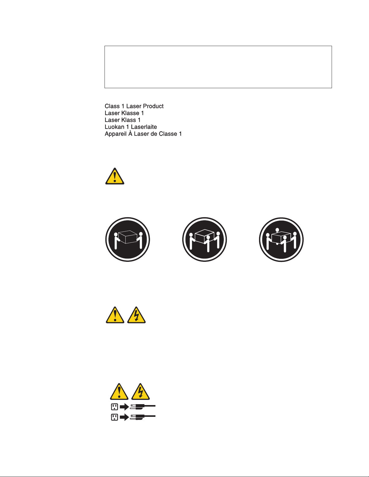
Statement 4
CAUTION:
Use safe practices when lifting.
≥ 18 kg (39.7 lb) ≥ 32 kg (70.5 lb) ≥ 55 kg (121.2 lb)
Statement 5
CAUTION:
The power control button on the device and the power switch on the power
supply do not turn off the electrical current supplied to the device. The device
also might have more than one power cord. To remove all electrical current from
the device, ensure that all power cords are disconnected from the power source.
2
1
Safety xi
Page 14
Statement 6
CAUTION:
If you install a strain-relief bracket option over the end of the power cord that is
connected to the device, you must connect the other end of the power cord to an
easily accessible power source.
Statement 8
CAUTION:
Never remove the cover on a power supply or any part that has the following
label attached.
Hazardous voltage, current, and energy levels are present inside any component
that has this label attached. There are no serviceable parts inside these
components. If you suspect a problem with one of these parts, contact a service
technician.
Statement 12
CAUTION:
The following label indicates a hot surface nearby.
Statement 26
xii System x3100 M5 Type 5457: Installation and Service Guide
Page 15
CAUTION:
Do not place any object on top of rack-mounted devices.
Statement 27
CAUTION:
Hazardous moving parts are nearby.
Rack Safety Information, Statement 2
DANGER
v Always lower the leveling pads on the rack cabinet.
v Always install stabilizer brackets on the rack cabinet.
v Always install servers and optional devices starting from the bottom of the
rack cabinet.
v Always install the heaviest devices in the bottom of the rack cabinet.
Safety xiii
Page 16

xiv System x3100 M5 Type 5457: Installation and Service Guide
Page 17

Chapter 1. The IBM System x3100 M5 Type 5457 server
This Installation and Service Guide contains information and instructions for setting
up your IBM System x3100 M5 Type 5457 server, instructions for installing some
optional devices, cabling and configuring the server, removing and replacing
devices, and diagnostics and troubleshooting information.
In addition to the instructions in Chapter 2, “Installing optional devices,” on page
27 for installing optional hardware devices, updating firmware and device drivers,
and completing the installation, IBM Business Partners must also complete the
steps in “Instructions for IBM Business Partners” on page 28.
1
The IBM System x3100 M5 Type 5457 server
self-contained, high performance tower system, which is scalable in cost,
configuration and performance.
Performance, ease of use, reliability, manageability and expansion capabilities were
key considerations in the design of the server. These design features make it
possible for you to customize the system hardware to meet your needs today and
provide flexible expansion capabilities for the future.
The server comes with a limited warranty. For information about the terms of the
warranty and getting service and assistance, see the IBM Warranty Information
document that comes with the server.
includes 4U or 5U models. It is a
The server contains IBM next generation technologies, which help increase
performance and reliability. For more information, see “What your server offers”
on page 14 and “Reliability, availability, and serviceability” on page 17.
You can obtain up-to-date information about the server and other IBM server
products at http://www.ibm.com/systems/x. At http://www.ibm.com/
supportportal, you can create a personalized support page by identifying IBM
products that are of interest to you. From this personalized page, you can subscribe
to weekly email notifications about new technical documents, search for
information and downloads, and access various administrative services.
If you participate in the IBM client reference program, you can share information
about your use of technology, best practices, and innovative solutions; build a
professional network; and gain visibility for your business. For more information
about the IBM client reference program, see http://www.ibm.com/ibm/
clientreference/.
If firmware and documentation updates are available, you can download them
from the IBM website. The server might have features that are not described in the
documentation that comes with the server, and the documentation might be
updated occasionally to include information about those features, or technical
updates might be available to provide additional information that is not included
in the server documentation. To check for updates, go to http://www.ibm.com/
supportportal.
1. Racks are measured in vertical increments of 4.45 cm (1.75 inches) each. Each increment is called a "U." A 1-U-high device is 1.75
inches tall
© Copyright IBM Corp. 2014
1
Page 18
Record information about the server in the following table.
Table 1. Record of the system information
Product name Machine Type (s) Model number Serial number
IBM System x3100
M5 server
Type 5457
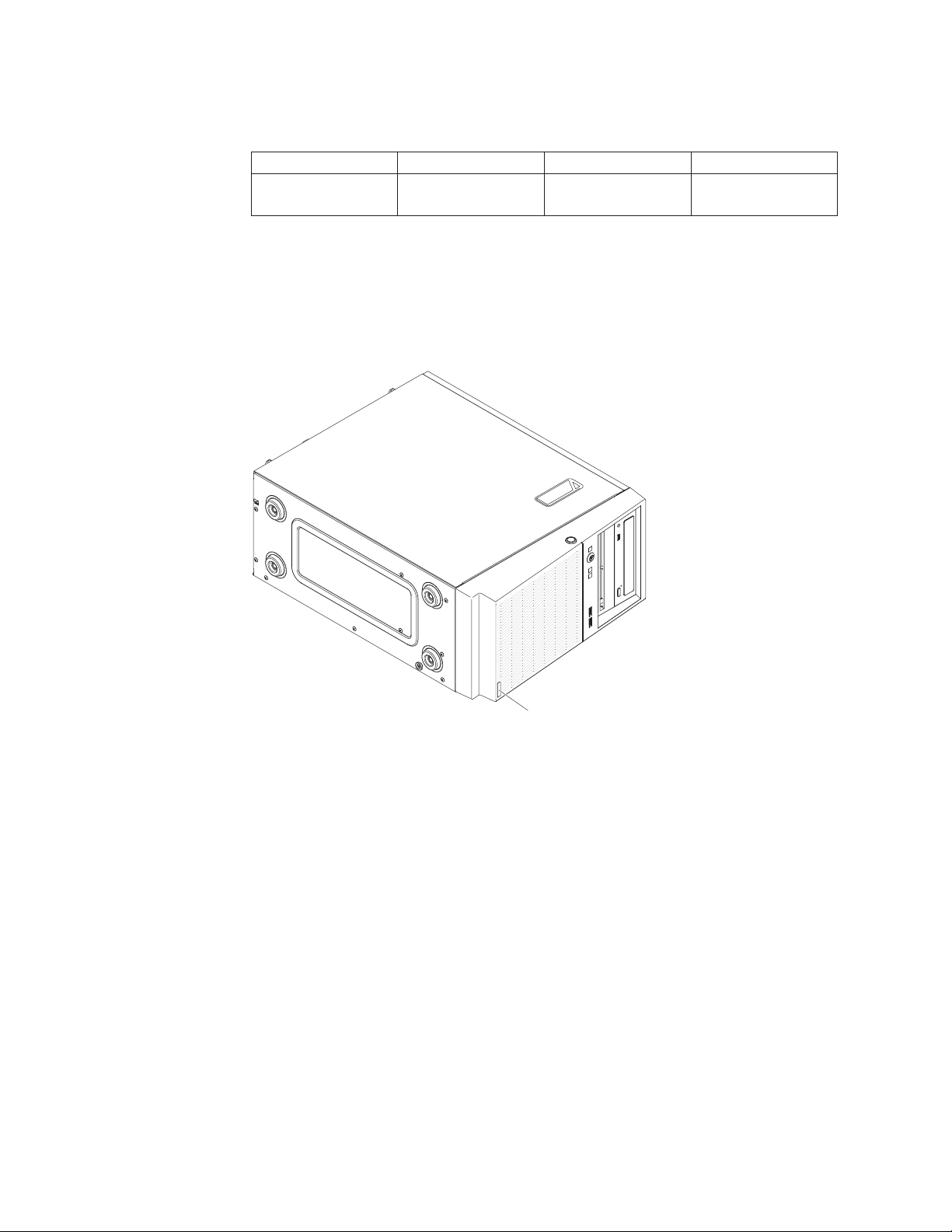
The model number and serial number are on the ID label on the front of the
server, as shown in the following illustrations for the respective 4U and 5U server
models.
Note: The illustrations in this document might differ slightly from your hardware.
Model number
and serial number
Figure 1. Location of model type/serial number of the 4U server model with non-hot-swap
power supplies
2 System x3100 M5 Type 5457: Installation and Service Guide
Page 19
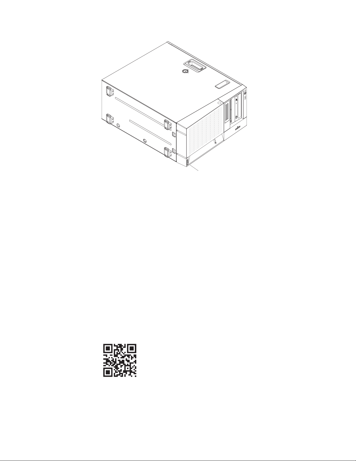
Model number
and serial number
Figure 2. Location of model type/serial number of the 5U server model with hot-swap power
supplies
Important: The server keys cannot be duplicated by a locksmith. If you lose them,
order replacement keys from the key manufacturer. The key serial number and the
telephone number of the manufacturer are on a tag that is attached to the keys.
In addition, the system service label, which is on the cover of the server, provides a
QR code for mobile access to service information. You can scan the QR code using
a QR code reader and scanner with a mobile device and get quick access to the
IBM Service Information website. The IBM Service Information website provides
additional information for parts installation and replacement videos, and error
codes for server support.
The following illustration shows the QR code (http://ibm.co/1ja7bP8):
Figure 3. QR code
You can download the IBM ServerGuide Setup and Installation CD to help you
configure the hardware, install device drivers, and install the operating system.
Chapter 1. The IBM System x3100 M5 Type 5457 server 3
Page 20

For a list of supported optional devices for the server, see http://www.ibm.com/
systems/info/x86servers/serverproven/compat/us.
See the Rack Installation Instructions document on the IBM System x Documentation
CD for complete rack installation and removal instructions.
The IBM Documentation CD
The IBM Documentation CD contains documentation for the server in Portable
Document Format (PDF) and includes the IBM Documentation Browser to help
you find information quickly.
Hardware and software requirements
The hardware and software requirements of the IBM Documentation CD.
The IBM Documentation CD requires the following minimum hardware and
software:
v Microsoft Windows or Red Hat Linux
v 100 MHz microprocessor
v 32 MB of RAM
v Adobe Acrobat Reader 3.0 (or later) or xpdf, which comes with Linux operating
systems
The Documentation Browser
Use the Documentation Browser to browse the contents of the CD, read brief
descriptions of the documents, and view documents, using Adobe Acrobat Reader
or xpdf.
The Documentation Browser automatically detects the regional settings in use in
your server and displays the documents in the language for that region (if
available). If a document is not available in the language for that region, the
English-language version is displayed. Use one of the following procedures to start
the Documentation Browser:
v If Autostart is enabled, insert the CD into the CD or DVD drive. The
Documentation Browser starts automatically.
v If Autostart is disabled or is not enabled for all users, use one of the following
procedures:
– If you are using a Windows operating system, insert the CD into the CD or
DVD drive and click Start > Run. In the Open field, type:
e:\win32.bat
where e is the drive letter of the CD or DVD drive, and click OK.
– If you are using Red Hat Linux, insert the CD into the CD or DVD drive;
then, run the following command from the /mnt/cdrom directory:
sh runlinux.sh
Select the server from the Product menu. The Available Topics list displays all the
documents for the server. Some documents might be in folders. A plus sign (+)
indicates each folder or document that has additional documents under it. Click
the plus sign to display the additional documents.
When you select a document, a description of the document is displayed under
Topic Description. To select more than one document, press and hold the Ctrl key
4 System x3100 M5 Type 5457: Installation and Service Guide
Page 21

while you select the documents. Click View Book to view the selected document
or documents in Acrobat Reader or xpdf. If you selected more than one document,
all the selected documents are opened in Acrobat Reader or xpdf.
To search all the documents, type a word or word string in the Search field and
click Search. The documents in which the word or word string appears are listed
in order of the most occurrences. Click a document to view it, and press Crtl+F to
use the Acrobat search function, or press Alt+F to use the xpdf search function
within the document.
Click Help for detailed information about using the Documentation Browser.
Related documentation
This Installation and Service Guide contains general information about the server
including how to set up and cable the server, how to install supported optional
devices, how to configure the server, and information to help you solve problems
yourself and information for service technicians.
The following documentation also comes with the server:
v Warranty Information
This document is in printed format and comes with the server. It contains
warranty terms and a pointer to the IBM Statement of Limited Warranty on the
IBM website.
v Important Notices
This document is in printed format and comes with the server. It contains
information about the safety, environmental, and electronic emission notices for
your IBM product.
v Environmental Notices and User Guide
This document is in PDF format on the IBM Documentation CD. It contains
translated environmental notices.
v IBM License Agreement for Machine Code
This document is in PDF on the IBM Documentation CD. It provides translated
versions of the IBM License Agreement for Machine Code for your product.
v Licenses and Attributions Document
This document is in PDF on the IBM Documentation CD. It provides the open
source notices.
v Safety Information
This document is in PDF on the IBM Documentation CD. It contains translated
caution and danger statements. Each caution and danger statement that appears
in the documentation has a number that you can use to locate the corresponding
statement in your language in the Safety Information document.
v Rack Installation Instructions
This printed document contains instructions for installing the server in a rack.
Depending on the server model, additional documentation might be included on
the IBM Documentation CD.
The ToolsCenter for System x and BladeCenter is an online information center that
contains information about tools for updating, managing, and deploying firmware,
Chapter 1. The IBM System x3100 M5 Type 5457 server 5
Page 22

device drivers, and operating systems. The ToolsCenter for System x and
BladeCenter is at http://www.ibm.com/support/entry/portal/
docdisplay?lndocid=TOOL-CENTER.
The server might have features that are not described in the documentation that
you received with the server. The documentation might be updated occasionally to
include information about those features, or technical updates might be available
to provide additional information that is not included in the server documentation.
These updates are available from the IBM website. To check for updates, go to
http://www.ibm.com/supportportal.
Notices and statements in this document
The caution and danger statements in this document are also in the multilingual
Safety Information document, which is on the IBM Documentation CD. Each
statement is numbered for reference to the corresponding statement in your
language in the Safety Information document.
The following notices and statements are used in this document:
v Note: These notices provide important tips, guidance, or advice.
v Important: These notices provide information or advice that might help you
avoid inconvenient or problem situations.
v Attention: These notices indicate potential damage to programs, devices, or data.
An attention notice is placed just before the instruction or situation in which
damage might occur.
v Caution: These statements indicate situations that can be potentially hazardous
to you. A caution statement is placed just before the description of a potentially
hazardous procedure step or situation.
v Danger: These statements indicate situations that can be potentially lethal or
extremely hazardous to you. A danger statement is placed just before the
description of a potentially lethal or extremely hazardous procedure step or
situation.
Server features and specifications
Use this information for an overview of the server features and specifications.
The following information is a summary of the features and specifications of the
4U server model with non-hot-swap power supplies. For the 5U server model with
hot-swap power supplies, please see the next sub-section. Depending on the
model, some features might not be available, or some specifications might not
apply.
Microprocessor (depending on the model):
v Supports one Intel dual-core or quad-core (Xeon E3-1200 V3 series)
processor
v Multi-chip Package processor architecture
v Designed for LGA 1150 socket
v Scalable up to four cores
v 32 KB instruction L1 cache, 32 KB data L1 cache, 256 KB
instruction/data L2 cache, and up to 8 MB L3 cache that is shared
among the cores
v Support for Intel Extended Memory 64 Technology (EM64T)
6 System x3100 M5 Type 5457: Installation and Service Guide
Page 23

Notes:
1. Use the Setup utility to determine the type and speed of the
microprocessors in the server
2. For a list of supported microprocessors, see http://www.ibm.com/
systems/info/x86servers/serverproven/compat/us.
Memory:
v Connectors: four dual inline memory module (DIMM) connectors,
two-way interleaved
v Minimum: 1 GB
v Maximum: 32 GB
v Types: PC3-12800 (single-rank or dual-rank), 1333 and 1600 MHz, ECC,
DDR3 unbuffered SDRAM DIMMs only
v Sizes: 1GB (single-rank) 2GB (single-rank) 4GB (dual-rank) 8GB
(dual-rank)
Fan:
v One system fan
v One option fan for PCIe card
Power supply:
v One fixed 350-watt or 300-watt power supply
Size:
v Height: 360 mm (14.17 in.)
v Depth: 480 mm (18.89 in.)
v Width: 180 mm (7.08 in.)
v Weight: 10 kg (22 lb) to 13 kg (28.66 lb) depending upon configuration
RAID controllers (depending on the model):
v ServeRAID H1110 SAS/SATA Controller that provides RAID levels 0, 1,
and 10.
v ServeRAID C100 capabilities that support RAID levels 0, 1, and 10
(RAID 5 upgrade available for IBM System x)
v ServeRAID M1115 SAS/SATA Controller that provides RAID levels 0, 1,
and 10 (RAID 5 upgrade available for IBM System x).
Environment:
v Power on:
– Temperature: 5°C to 40°C (40°F to 104°F) up to 950 mm (3,117 ft);
above 950 m, derated maximum air temperature is 1°C / 175 m
– Humidity, non-condensing: -12°C dew point (10.4°F) and 8% ~ 85%
relative humidity
– Maximum dew point: 24°C (75°F)
– Maximum altitude: 3,050 m (10,000 ft) and 5°C to 28°C (41°F to 82°F)
– Maximum rate of temperature change: 5°C per hour (41°F per hour)
for tape drive, 20°C per hour (68°F per hour) for hard disk drives
v Power off:
– Temperature: 5°C to 45°C (41°F to 113°F)
– Humidity: 8%~85%
– Maximum dew point: 27°C (80.6°F)
v Storage (non-operating):
Chapter 1. The IBM System x3100 M5 Type 5457 server 7
Page 24

– Temperature: 1°C to 60°C (33.8°F to 140°F)
– Altitude: 3,050 m (10,000)
– Humidity: 5%~80%
– Maximum dew point: 29°C (84.2°F)
v Shipment (non-operating)
– Temperature: -40°C to 60°C (-40°F to 140°F)
– Altitude: 10.700 m (35,105 ft)
– Humidity: 5%~100%
– Maximum dew point: 29°C (84.2°F)
v Particulate contamination:
Attention: Design to ASHRAE Class A3, ambient of 40°C, with relaxed
support:
– The system will support cloud-like workload with no performance
degradation acceptable (Turbo-Off).
– Under no circumstance can any combination of worst-case workload
and configuration result in system shutdown or design exposure at
40°C.
Drives (depending on the model):
v Hard disk drives: up to four 3.5-inch simple-swap SATA
v One of the following SATA attached optical drives:
– DVD-ROM
– Tape drive
Drive bays (depending on the model):
v Two 5.25-inch half-high bays (one optical drive installed).
v Four 3.5-inch hard disk drive bays
Attention: As a general consideration, do not mix standard 512-byte and
advanced 4-KB format drives in the same RAID array because it might
lead to potential performance issues.
Integrated functions:
v Integrated management module II (IMM2), which consolidates multiple
management functions in a single chip
v BroadCom 5717 Gb Ethernet controller with TCP/IP Offload Engine
(TOE) and Wake on LAN support
v Integrated SATA controller
v Seven Universal Serial Bus (USB) ports:
– Two USB 3.0 ports on the front. (Due to the limitation of USB 3.0, the
front USB is not usable for RHEL 5.10, Vmware 5.1 and Vmware 5.5.)
– Four USB 2.0 ports on the rear
– One internal USB 2.0 port for an optional tape drive
v Six SATA ports (blue-colored ports for DVD drive or optional tape drive)
v One serial port
v Two Ethernet ports
v One VGA port
Heat output:
Approximate heat output:
8 System x3100 M5 Type 5457: Installation and Service Guide
Page 25

v Minimum configuration: 341 Btu per hour (100 watts)
v Maximum configuration: 1194 Btu per hour (350 watts)
Expansion slots:
v One PCI Express x16 slot
v One PCI Express x8 slot
v One PCI Express x8 slot
v One PCI Express x4 slot
Electrical input:
v Sine-wave input (50-60 Hz) required
v Input voltage low range:
– Minimum: 100 V AC
– Maximum: 127 V AC
v Input voltage high range:
– Minimum: 200 V ac
– Maximum: 240 V ac
v Input kilovolt-amperes (kVA), approximately:
– Minimum: 0.100 kVA (all models)
– Maximum: 0.350 kVA
Acoustical noise emissions
v Sound power, idling: 5.0 bels
v Sound power, operating: 5.0 bels
Notes:
1. Power consumption and heat output vary depending on the number and type
of optional features installed and the power-management optional features in
use.
2. The noise emission level stated is the declared (upper limit) sound power level,
in bels, for a random sample of machines. All measurements are made in
accordance with ISO 7779 and reported in conformance with ISO 9296.
EU Regulation 617/2013 Technical Documentation:
International Business Machines Corporation
New Orchard Road
Armonk, New York 10504
http://www.ibm.com/customersupport/
For more information on the energy efficiency program, go to
http://www.ibm.com/systems/x/hardware/energy-star/index.html
Product Type:
Computer server
Year first manufactured:
2014
Internal/external power supply efficiency:
v http://www.plugloadsolutions.com/psu_reports/IBM_DPS-430EB
%20A_430W_SO-385_Report.pdf
v http://www.plugloadsolutions.com/psu_reports/DELTA
%20ELECTRONICS_DPS-300AB-62%20A_ECOS
%202471_300W_Report.pdf
Chapter 1. The IBM System x3100 M5 Type 5457 server 9
Page 26

Maximum power (watts):
See Power supply.
Idle state power (watts):
102
Sleep mode power (watts):
Not applicable for servers.
Off mode power (watts):
6
Noise levels (the declared A-weighed sound power level of the computer):
See Acoustical noise emissions.
Test voltage and frequency:
230V/50Hzor60Hz
Total harmonic distortion of the electricity supply system:
The maximum harmonic content of the input voltage waveform will be
equal or less than 2%. The qualification is compliant with EN 61000-3-2.
Information and documentation on the instrumentation set-up and circuits used
for electrical testing:
ENERGY STAR Test Method for Computer Servers; ECOVA Generalized
Test Protocol for Calculating the Energy Efficiency of Internal Ac-Dc and
Dc-Dc Power Supplies.
Measurement methodology used to determine information in this document:
ENERGY STAR Servers Version 2.0 Program Requirements; ECOVA
Generalized Test Protocol for Calculating the Energy Efficiency of Internal
Ac-Dc and Dc-Dc Power Supplies.
The following information is a summary of the features and specifications of the
5U server model with hot-swap power supplies. For the 4U server model with
non-hot-swap power supplies, please see the above sub-section. Depending on the
model, some features might not be available, or some specifications might not
apply.
Microprocessor (depending on the model):
v Supports one Intel dual-core or quad-core (Xeon E3-1200 V3 series)
processor
v Multi-chip Package processor architecture
v Designed for LGA 1150 socket
v Scalable up to four cores
v 32 KB instruction L1 cache, 32 KB data L1 cache, 256 KB
instruction/data L2 cache, and up to 8 MB L3 cache that is shared
among the cores
v Support for Intel Extended Memory 64 Technology (EM64T)
Notes:
1. Use the Setup utility to determine the type and speed of the
microprocessors in the server
2. For a list of supported microprocessors, see http://www.ibm.com/
systems/info/x86servers/serverproven/compat/us.
Memory:
v Connectors: four dual inline memory module (DIMM) connectors,
two-way interleaved
10 System x3100 M5 Type 5457: Installation and Service Guide
Page 27

v Minimum: 1 GB
v Maximum: 32 GB
v Types: PC3-12800 (single-rank or dual-rank), 1333 and 1600 MHz, ECC,
DDR3 unbuffered SDRAM DIMMs only
v Sizes: 1GB (single-rank) 2GB (single-rank) 4GB (dual-rank) 8GB
(dual-rank)
Fan:
v One system fan
v One option fan for PCIe card
Power supply:
v One or two redundant 430-watt power supply
Size:
v Height: 438.60 mm (17.27 in.)
v Depth: 569.11 mm (22.41 in.)
v Width: 217.3 mm (8.56 in.)
v Weight: 19.6 kg (43 lb) to 22 kg (48.50 lb) depending upon configuration
RAID controllers (depending on the model):
v ServeRAID H1110 SAS/SATA Controller that provides RAID levels 0, 1,
and 10.
v ServeRAID C100 capabilities that support RAID levels 0, 1, and 10
(RAID 5 upgrade available for IBM System x)
v ServeRAID M1115 SAS/SATA Controller that provides RAID levels 0, 1,
and 10 (RAID 5 upgrade available for IBM System x).
Environment:
v Power on:
– Temperature: 5°C to 40°C (40°F to 104°F) up to 950 mm (3,117 ft);
– Humidity, non-condensing: -12°C dew point (10.4°F) and 8% ~ 85%
– Maximum dew point: 24°C (75°F)
– Maximum altitude: 3,050 m (10,000 ft) and 5°C to 28°C (41°F to 82°F)
– Maximum rate of temperature change: 5°C per hour (41°F per hour)
v Power off:
– Temperature: 5°C to 45°C (41°F to 113°F)
– Humidity: 8%~85%
– Maximum dew point: 27°C (80.6°F)
v Storage (non-operating):
– Temperature: 1°C to 60°C (33.8°F to 140°F)
– Altitude: 3,050 m (10,000)
– Humidity: 5%~80%
– Maximum dew point: 29°C (84.2°F)
v Shipment (non-operating)
– Temperature: -40°C to 60°C (-40°F to 140°F)
– Altitude: 10.700 m (35,105 ft)
above 950 m, derated maximum air temperature is 1°C / 175 m
relative humidity
for tape drive, 20°C per hour (68°F per hour) for hard disk drives
Chapter 1. The IBM System x3100 M5 Type 5457 server 11
Page 28

– Humidity: 5%~100%
– Maximum dew point: 29°C (84.2°F)
v Particulate contamination:
Attention: Design to ASHRAE Class A3, ambient of 40°C, with relaxed
support:
– The system will support cloud-like workload with no performance
degradation acceptable (Turbo-Off).
– Under no circumstance can any combination of worst-case workload
and configuration result in system shutdown or design exposure at
40°C.
Drives (depending on the model):
v Hard disk drives: up to eight 2.5-inch hot-swap SATA/SAS or four
3.5-inch hot-swap SATA/SAS
v One of the following SATA attached optical drives:
– DVD-ROM
Drive bays (depending on the model):
v Two 5.25-inch half-high bays (one optical drive installed).
v Eight 2.5-inch hard disk drive bays
v Four 3.5-inch hard disk drive bays
Attention: As a general consideration, do not mix standard 512-byte and
advanced 4-KB format drives in the same RAID array because it might
lead to potential performance issues.
Integrated functions:
v Integrated management module II (IMM2), which consolidates multiple
management functions in a single chip
v BroadCom 5717 Gb Ethernet controller with TCP/IP Offload Engine
(TOE) and Wake on LAN support
v Integrated SATA controller
v Seven Universal Serial Bus (USB) ports:
– Two USB 3.0 ports on the front. (Due to the limitation of USB 3.0, the
front USB is not usable for RHEL 5.10, Vmware 5.1 and Vmware 5.5.)
– Four USB 2.0 ports on the rear
– One internal USB 2.0 port for an optional tape drive
v Six SATA ports (blue-colored ports for DVD drive or optional tape drive)
v One serial port
v Two Ethernet ports
v One VGA port
Heat output:
Approximate heat output:
v Minimum configuration: 341 Btu per hour (100 watts)
v Maximum configuration: 1726 Btu per hour (506 watts)
Expansion slots:
v One PCI Express x16 slot
v One PCI Express x8 slot
v One PCI Express x8 slot
12 System x3100 M5 Type 5457: Installation and Service Guide
Page 29

v One PCI Express x4 slot
Electrical input:
v Sine-wave input (50-60 Hz) required
v Input voltage low range:
– Minimum: 100 V AC
– Maximum: 127 V AC
v Input voltage high range:
– Minimum: 200 V ac
– Maximum: 240 V ac
v Input kilovolt-amperes (kVA), approximately:
– Minimum: 0.100 kVA (all models)
– Maximum: 0.506 kVA
Acoustical noise emissions
v Sound power, idling: 5.0 bels
v Sound power, operating: 5.0 bels
Notes:
1. Power consumption and heat output vary depending on the number and type
of optional features installed and the power-management optional features in
use.
2. The noise emission level stated is the declared (upper limit) sound power level,
in bels, for a random sample of machines. All measurements are made in
accordance with ISO 7779 and reported in conformance with ISO 9296.
EU Regulation 617/2013 Technical Documentation:
International Business Machines Corporation
New Orchard Road
Armonk, New York 10504
http://www.ibm.com/customersupport/
For more information on the energy efficiency program, go to
http://www.ibm.com/systems/x/hardware/energy-star/index.html
Product Type:
Computer server
Year first manufactured:
2014
Internal/external power supply efficiency:
v http://www.plugloadsolutions.com/psu_reports/IBM_DPS-430EB
%20A_430W_SO-385_Report.pdf
v http://www.plugloadsolutions.com/psu_reports/DELTA
%20ELECTRONICS_DPS-300AB-62%20A_ECOS
%202471_300W_Report.pdf
Maximum power (watts):
See Power supply.
Idle state power (watts):
102
Sleep mode power (watts):
Not applicable for servers.
Chapter 1. The IBM System x3100 M5 Type 5457 server 13
Page 30

Off mode power (watts):
6
Noise levels (the declared A-weighed sound power level of the computer):
See Acoustical noise emissions.
Test voltage and frequency:
230V/50Hzor60Hz
Total harmonic distortion of the electricity supply system:
The maximum harmonic content of the input voltage waveform will be
equal or less than 2%. The qualification is compliant with EN 61000-3-2.
Information and documentation on the instrumentation set-up and circuits used
for electrical testing:
ENERGY STAR Test Method for Computer Servers; ECOVA Generalized
Test Protocol for Calculating the Energy Efficiency of Internal Ac-Dc and
Dc-Dc Power Supplies.
Measurement methodology used to determine information in this document:
ENERGY STAR Servers Version 2.0 Program Requirements; ECOVA
Generalized Test Protocol for Calculating the Energy Efficiency of Internal
Ac-Dc and Dc-Dc Power Supplies.
What your server offers
The server uses the following features and technologies.
v Integrated management module II (IMM2)
The integrated management module II (IMM2) is the second generation of the
IMM. The IMM2 is the common management controller for IBM System x
hardware. The IMM2 consolidates multiple management functions in a single
chip on the server system board.
Some of the features that are unique to the IMM2 are enhanced performance,
expanded compatibility with blade servers, higher-resolution remote video,
expanded security options, and Feature on Demand enablement for hardware
and firmware options.
For additional information, see “Using the Integrated Management Module II
(IMM2)” on page 105 and the Integrated Management Module II User’s Guide at
http://www-947.ibm.com/support/entry/portal/docdisplay?lndocid=migr-
5086346.
v UEFI-compliant server firmware
The IBM System x Server Firmware offers several features, including Unified
Extensible Firmware Interface (UEFI) version 2.1 compliance, enhanced
reliability, availability, and serviceability (RAS) capabilities, and basic
input/output system (BIOS) compatibility support. UEFI replaces the legacy
BIOS. UEFI defines a standard interface between the operating system, platform
firmware and external devices, and offers capabilities that far exceeds that of the
legacy BIOS.
The server design combines the UEFI capabilities and features with legacy BIOS
compatibility. The server is capable of booting UEFI-compliant operating
systems, BIOS-based operating systems, and BIOS-based adapters as well as
UEFI-compliant adapters.
Note: The server does not support DOS (Disk Operating System).
v Dynamic System Analysis (DSA)
14 System x3100 M5 Type 5457: Installation and Service Guide
Page 31

Dynamic System Analysis (DSA) collects and analyzes system information to aid
in diagnosing server problems. DSA collects the following information about the
server:
– Drive health information
– Event logs for ServeRAID controllers and service processors
– Hardware inventory, including PCI and USB information
– Installed applications and hot fixes (available in DSA Portable only)
– Kernel modules (available in DSA Portable only)
– Light path diagnostics status
– Network interfaces and settings
– Performance data and details about processes that are running
– RAID and controller configuration
– Service processor (Integrated Management Module II (IMM2) status and
configuration
– System configuration
– Vital product data and firmware information
– IMM2 configuration information
– IMM2 enviromentals information
– Option card driver and firmware information
DSA creates a DSA log, which is a chronologically ordered merge of the
system-event log (as the IPMI event log), the integrated management module II
(IMM2) event log (as the ASM event log), and the operating-system event logs.
You can send the DSA log as a file to a support representative or view the
information as a text file or HTML file.
v VMware ESXi embedded hypervisor
An optional USB flash device with VMware ESXi embedded hypervisor software
is available for purchase. Hypervisor is virtualization software that enables
multiple operating systems to run on a host system at the same time. Install the
USB flash device in the USB embedded hypervisor flash device connectors on
the system board (see “System-board internal connectors” on page 30). See
“Using the embedded hypervisor” on page 109 for additional information.
v Features on Demand
If a Features on Demand feature is integrated in the server or in an optional
device that is installed in the server, you can purchase an activation key to
activate the feature. For information about Features on Demand, see
/http://www.ibm.com/systems/x/fod/.
v High-performance graphics controller
The server comes with an onboard high-performance graphics controller that
supports high resolutions and includes many performance-enhancing features
for the operating-system environment..
v Mobile access to IBM Service Information website
The server provides a QR code on the system service label, which is on the
cover of the server, that you can scan using a QR code reader and scanner with
a mobile device to get quick access to the IBM Service Information website. The
IBM Service Information website provides additional information for parts
installation and replacement videos, and error codes for server support. For the
QR code, see QR code information on page Chapter 1, “The IBM System x3100
M5 Type 5457 server,” on page 1.
v IBM Systems Director
Chapter 1. The IBM System x3100 M5 Type 5457 server 15
Page 32

IBM Systems Director is a platform-management foundation that streamlines the
way you manage physical and virtual systems in a heterogeneous environment.
By using industry standards, IBM Systems Director supports multiple operating
systems and virtualization technologies for IBM and non-IBM x86 platforms. For
more information, see the IBM Systems Director Information Center at and “IBM
Systems Director” on page 18.
v IBM Enterprise X-Architecture technology
®
IBM X-Architecture
technology combines proven, innovative IBM designs to
make your Intel-processor-based server powerful, scalable, and reliable.
v IBM ServerGuide Setup and Installation CD
The ServerGuide Setup and Installation CD, which you can download from the
web, provides programs to help you set up the server and install a Windows
operating system. The ServerGuide program detects installed optional hardware
devices and provides the correct configuration programs and device drivers. For
more information about the ServerGuide Setup and Installation CD, see “Using the
ServerGuide Setup and Installation CD” on page 96.
v Integrated network support
The server comes with an integrated dual-port Intel 82574L Gigabit Ethernet
controller, which supports connection to a 10 Mbps, 100 Mbps, or 1000 Mbps
network. For more information, see “Configuring the Gigabit Ethernet
controller” on page 110.
v PCI adapter capabilities
The server has four PCI interface slots. The slots can support PCI Express or
PCI-X adapters. See “Replacing an adapter” on page 269 for detailed
information.
v Large system-memory capacity
The server supports up to 32 GB of system memory when unbuffered DIMMs
are installed. The memory controller supports error correcting code (ECC) and
non-error correcting code for up to 4 industry-standard PC3-10600R-999
(single-rank or dual-rank), 1066 and 1333 MHz, DDR3 (third-generation
double-data-rate) unbuffered synchronous dynamic random access memory
(SDRAM) dual inline memory modules (DIMMs).
v Redundant connection
The addition of an optional network interface card (NIC) provides a failover
capability to a redundant Ethernet connection. If a problem occurs with the
primary Ethernet connection, all Ethernet traffic that is associated with the
primary connection is automatically switched to the redundant NIC. If the
applicable device drivers are installed, this switching occurs without data loss
and without user intervention.
v ServeRAID support
The ServeRAID adapter provides hardware redundant array of independent
disks (RAID) support to create configurations. The standard RAID adapter
provides RAID levels 0, 1, and 10. An optional RAID adapter is available for
purchase.
v Dual-core or quad-core processing
™
The server supports one Intel Xeon
dual-core or quad-core microprocessor.
v Systems-management capabilities
The server comes with an integrated management module II (IMM2). When the
IMM2 is used with the systems-management software that comes with the
16 System x3100 M5 Type 5457: Installation and Service Guide
Page 33

server, you can manage the functions of the server locally and remotely. The
IMM2 also provides system monitoring, event recording, and network alert
capability.
v TCP/IP offload engine (TOE) support
The Ethernet controller in the server support TOE, which is a technology that
offloads the TCP/IP flow from the microprocessor and I/O subsystem to
increase the speed of the TCP/IP flow. When an operating system that supports
TOE is running on the server and TOE is enabled, the server supports TOE
operation. See the operating-system documentation for information about
enabling TOE. The Windows operating system requires that the Windows
Scalable Network Pack (SNP) be installed for TOE support.
Reliability, availability, and serviceability
Three important computer design features are reliability, availability, and
serviceability (RAS). The RAS features help to ensure the integrity of the data that
is stored in the server, the availability of the server when you need it, and the ease
with which you can diagnose and correct problems.
Your server has the following RAS features:
v Advanced Configuration and Power Interface (ACPI)
v Advanced Desktop Management Interface (DMI) features
v Automatic BIOS recovery to a backup image
v Automatic error retry or recovery
v Automatic memory downsizing on error detection
v Automatic restart on nonmaskable interrupt (NMI)
v Automatic Server Restart (ASR) logic supporting a system restart when the
operating system becomes unresponsive
v Automatic server restart after a power failure, based on the UEFI setting
v Availability of microcode level
v Boot-block recovery
v Built-in, menu-driven setup, system configuration, and redundant array of
independent disks (RAID) configuration
v Built-in monitoring for fan, power, temperature, and voltage
v Cooling fans with speed-sensing capability
v Customer support center that is available 24 hours a day, 7 days a week
v Diagnostic support of ServeRAID adapters
v Error codes and messages
v Error correcting code (ECC) double-data-rate 3 (DDR3) synchronous dynamic
random-access memory (SDRAM) with serial presence detect (SPD)
v Error logging of POST failures
v Simple-swap Serial ATA (SATA) hard disk drives
v Integrated Ethernet controller
v Intelligent Platform Management Interface (IPMI)
v Key-lock support for physical security
v Memory change messages posted to the error log
v integrated management module II (IMM2)
v Power management
v Power-on self-test (POST)
v Read-only memory (ROM) checksums
v Redundant Ethernet capabilities (requires an optional Ethernet adapter) with
failover support
v ROM-based diagnostic programs
2
2. Service availability will vary by country. Response time varies; may exclude holidays.
Chapter 1. The IBM System x3100 M5 Type 5457 server
17
Page 34

v Simple-swap Serial Advanced Technology Attachment (SATA) hard disk drives
v Standby voltage for system-management features and monitoring
v System auto-configuring from the configuration menu
v System-error LED on the front bezel and diagnostic LEDs on the system board
v System-error logging (POST and IMM2)
v Upgradeable integrated management module II (IMM2) firmware
v Upgradeable microcode for POST, server firmware, and read-only memory
(ROM) resident code, locally or over a LAN
v Vital product data (VPD); includes serial-number information and replacement
part numbers, stored in nonvolatile memory, for easier remote maintenance
v Wake on LAN capability
IBM Systems Director
IBM Systems Director is a platform-management foundation that streamlines the
way you manage physical and virtual systems in a heterogeneous environment. By
using industry standards, IBM Systems Director supports multiple operating
systems and virtualization technologies in IBM and non-IBM x86 platforms.
Through a single user interface, IBM Systems Director provides consistent views
for viewing managed systems, determining how these systems relate to one other,
and identifying their statuses, helping to correlate technical resources with business
needs. A set of common tasks that are included with IBM Systems Director
provides many of the core capabilities that are required for basic management,
which means instant out-of-the-box business value. The common tasks include
discovery, inventory, configuration, system health, monitoring, updates, event
notification, automation for managed systems, hardware log, power, and light
path.
The IBM Systems Director web and command-line interfaces provide a consistent
interface that is focused on driving these common tasks and capabilities:
v Discovering, navigating, and visualizing systems on the network with the
detailed inventory and relationships to the other network resources
v Notifying users of problems that occur on systems and the ability to isolate the
source of the problem
v Notifying users when systems need updates and distributing and installing
updates on a schedule
v Analyzing real-time data for systems and setting critical thresholds that notify
the administrator of emerging problems
v Configuring settings of a single system and creating a configuration plan that
can apply those settings to multiple systems
v Updating installed plug-ins to add new features and functions to the base
capabilities
v Managing the life cycles of virtual resources
For more information about IBM Systems Director, see the IBM Systems Director
Information Center at http://pic.dhe.ibm.com/infocenter/director/pubs/
index.jsp?topic=%2Fcom.ibm.director.main.helps.doc%2Ffqm0_main.html, and the
Systems Management web page at http://www.ibm.com/systems/management,
which presents an overview of IBM Systems Management and IBM Systems
Director.
18 System x3100 M5 Type 5457: Installation and Service Guide
Page 35

Server controls, LEDs, and power
This section describes the controls and light-emitting diodes (LEDs) and how to
turn the server on and off.
For the locations of other LEDs on the system board, see “System-board LEDs” on
page 34.
Front view
The following illustrations respectively show the controls, LEDs and connectors on
the front of the 4U and 5U server models.
System error
LED
Hard disk drive
activity LED
Power-control
button
Power-on LED
Figure 4. Front view of 4U server model with non-hot-swap power supplies (bezel installed)
DVD drive activity
LED(green)
DVD-eject
button
USB 1
USB 2
Chapter 1. The IBM System x3100 M5 Type 5457 server 19
Page 36

System error
LED
Hard disk drive
activity LED
Power-control
button
Power-on LED
Front information
panel
Simple-swap
hard disk drive
DVD drive activity
LED(green)
DVD-eject
button
USB 1
USB 2
Figure 5. Front view of 4U server model with non-hot-swap power supplies (bezel removed)
Power-control button
Power-on LED
Front information
panel
DVD drive
activity LED
(green)
Hard disk drive activity LED
System error LED
DVD-eject
button
USB 2
USB 1
Figure 6. Front view of 5U server model with hot-swap power supplies (lower and upper
bezel installed)
20 System x3100 M5 Type 5457: Installation and Service Guide
Page 37

Error LED
(yellow)
Activity LED
(green)
Figure 7. Front view of 5U server model with hot-swap power supplies (lower and upper
bezel installed) (Eight 2.5" hard disk drive configuration)
Activity LED
(green)
Error LED
(yellow)
Figure 8. Front view of 5U server model with hot-swap power supplies (lower and upper
bezel installed) (Four 3.5" hard disk drive configuration)
v Power control button and power-on LED:
Press this button to turn the server on and off manually. The states of the
power-on LED are as follows:
Chapter 1. The IBM System x3100 M5 Type 5457 server 21
Page 38

– Off: AC power is not present, or the power supply or the LED itself has
failed.
– Flashing rapidly (4 times per second): The server is partially on, but not
ready to be fully turned on. The power-control button is disabled. This will
last approximately 1 to 3 minutes.
– Flashing slowly (once per second): The server is ready to be turned on. You
can press the power-control button to turn on the server.
– Lit: The server is turned on.
v Hard disk drive activity LEDs:
When this LED is flashing, it indicates that the associated hard disk drive is in
use.
v System-error LED:
When this yellow LED is lit, it indicates that a system error has occurred. An
LED on the system board might also be lit to help isolate the error.
See“Diagnostic tools” on page 124 for additional information.
v USB connectors:
Connect USB devices to these connectors.
v DVD eject button:
Press this button to release a DVD or CD from the DVD drive.
v DVD drive activity LED:
When this LED is lit, it indicates that the DVD drive is in use.
v Hot-swap hard disk drive activity LED (some models):
On some server models, each hot-swap drive has a hard disk drive activity LED.
When this green LED is flashing, it indicates that the drive is in use.
When the drive is removed, this LED also is visible on the SAS/SATA
backplane, next to the drive connector. The backplane is the printed circuit board
behind drive bays 4 through 7 on 3.5-inch hard disk drive models.
v Hot-swap hard disk drive status LED (some models):
On some server models, each hot-swap hard disk drive has an yellow status
LED. If this yellow status LED for a drive is lit, it indicates that the associated
hard disk drive has failed.
If an optional ServeRAID adapter is installed in the server and the LED flashes
slowly (one flash per second), the drive is being rebuilt. If the LED flashes
rapidly (three flashes per second), the adapter is identifying the drive.
When the drive is removed, this LED also is visible on the SAS/SATA
backplane, below the hot-swap hard disk drive activity LED.
22 System x3100 M5 Type 5457: Installation and Service Guide
Page 39

Rear view
The following illustrations respectively show the controls, LEDs and connectors on
the rear of the 4U and 5U server models.
Power connector
Serial 1 (Com1)
USB connectors
Power switch
Ethernet link status
LED
Video
Ethernet
connector 1
Ethernet transmit/
receive activity
LED
Ethernet link status
LED
Ethernet
connector 2
Ethernet transmit/
receive activity
LED
Figure 9. Rear view of 4U server model with non-hot-swap power supplies (no power supply
LEDs present)
Power connector
Fault (error)LED (yellow)
DC power LED (green)
AC Power LED (green)
Serial 1 (Com1)
Video
USB connectors
Ethernet link status
LED
Ethernet
connector 1
Ethernet transmit/
receive activity
LED
Ethernet link status
LED
Ethernet
connector 2
Ethernet transmit/
receive activity
LED
Figure 10. Rear view of 4U server model with non-hot-swap power supplies (power supply
LEDs present)
Chapter 1. The IBM System x3100 M5 Type 5457 server 23
Page 40

AC Power LED (green)
DC power LED (green)
Fault (error)LED (yellow)
Serial (Com1)
Power connectors
Video
USB connectors
Figure 11. Rear view of 5U server model with hot-swap power supplies
Ethernet
connector 1
Ethernet
connector 2
Ethernet link
status LED
Ethernet transmit/
receive activity LED
v Power connector: Connect the power cord to this connector.
v AC power LED: This green LED provides status information about the power
supply. During typical operation, both the ac and dc power LEDs are lit.
v DC power LED: This green LED provides status information about the power
supply. During typical operation, both the ac and dc power LEDs are lit.
v Fault-error LED: When this yellow LED is lit, it indicates that the power supply
has failed..
v Serial connector: Connect a 9-pin serial device to this connector. The serial port
is shared with the integrated management module II (IMM2). The IMM2 can
take control of the shared serial port to redirect serial traffic, using Serial over
LAN (SOL).
v Video connector: Connect a monitor to this connector.
v USB connectors: Connect USB devices to these connectors.
v NMI button: Press this button to force a nonmaskable interrupt to the
microprocessor. It allows you to blue screen the server and take a memory
dump (use this button only when directed by the IBM service support). You
might have to use a pen or the end of a straightened paper clip to press the
button.
v Ethernet connector: Use either of these connectors to connect the server to a
network. When you use the Ethernet 1 connector, the network can be shared
with the IMM2 through a single network cable.
v Ethernet transmit/receive activity LED: This LED is on the Ethernet connector.
When this LED is flashing, it indicates that there is activity between the server
and the network..
v Ethernet link status LED: This LED is on the Ethernet connector. When this
LED is lit, it indicates that there is an active connection on the Ethernet port.
24 System x3100 M5 Type 5457: Installation and Service Guide
Page 41

Server power features
When the server is connected to an ac power source but is not turned on, the
operating system does not run, and all core logic except for the integrated
management module II (IMM2) is shut down; however, the server can respond to
requests from IMM2, such as a remote request to turn on the server.
The power-on LED flashes to indicate that the server is connected to an ac power
source but is not turned on.
Turning on the server
Use this information to turn on the server.
About this task
Approximately 5 seconds after the server is connected to input power, one or more
fans might start running and the power-on LED flashes quickly. Approximately 10
seconds after the server is connected to input power, the power-on button becomes
active. After the power-on button becomes active, the power-on LED flashes
slowly. You can turn on the server by pressing the power-on button.
Procedure
1. Press the power-on button to turn on the server.
2. The server can also be turned on in any of the following ways:
v If a power failure occurs while the server is turned on, the server will restart
automatically when power is restored.
v If your operating system supports the Wake on LAN feature, the Wake on
LAN feature can turn on the server.
What to do next
1. When 4 GB or more of memory (physical or logical) is installed, some memory
is reserved for various system resources and is unavailable to the operating
system. The amount of memory that is reserved for system resources depends
on the operating system, the configuration of the server, and the configured
PCI options.
2. When you turn on the server with external graphical adapters installed, the
IBM logo displays on the screen after approximately 3 minutes. This is normal
operation while the system loads.
3. Make sure the left-side cover is closed.
Chapter 1. The IBM System x3100 M5 Type 5457 server 25
Page 42

Turning off the server
Use this information to turn off the server.
About this task
When you turn off the server and leave it connected to input power, the server can
respond to requests to the service processor (the integrated management module),
such as a remote request to turn on the server. While the server remains connected
to input power, one or more fans might continue to run. To remove all power from
the server, you must disconnect it from the power source.
Some operating systems require an orderly shutdown before you turn off the
server. See your operating-system documentation for information about shutting
down the operating system.
Statement 5
CAUTION:
The power control button on the device do not turn off the electrical current
supplied to the device. The device also might have more than one power cord.
To remove all electrical current from the device, ensure that all power cords are
disconnected from the power source.
2
1
Procedure
The server can be turned off in any of the following ways:
v You can turn off the server from the operating system, if your operating system
supports this feature. After an orderly shutdown of the operating system, the
server will turn off automatically.
v You can press the power-control button to start an orderly shutdown of the
operating system and turn off the server, if your operating system supports this
feature.
v If the operating system stops functioning, you can press and hold the
power-control button for more than 4 seconds to turn off the server.
v The server can be turned off by Wake on LAN feature with the following
limitation:
v The integrated management module II (IMM2) can turn off the server as an
automatic response to a critical system failure.
26 System x3100 M5 Type 5457: Installation and Service Guide
Page 43

Chapter 2. Installing optional devices
This chapter provides detailed instructions for installing optional hardware devices
in the server.
Before you begin
In addition to the instructions in this chapter for installing optional hardware
devices, updating the firmware and device drivers, and completing the installation,
IBM Business Partners must also complete the steps in “Instructions for IBM
Business Partners” on page 28.
Important: To help ensure that the devices that you install work correctly and do
not introduce problems, observe the following precautions.
Procedure
1. Make sure that the server and the installed firmware levels support the devices
that you are installing. If necessary, update the UEFI and IMM firmware and
any other firmware that is stored on the system board. For information about
where firmware is stored in the server, see “Updating the firmware” on page
93. For a list of supported optional devices for the server, see
http://www.ibm.com/systems/info/x86servers/serverproven/compat/us.
2. Use the best practices to apply current firmware and device-driver updates for
the server and optional devices. To download the “IBM System x Firmware
Update Best Practices” document, go to www.ibm.com/support/entry/portal/
docdisplay?lndocid=MIGR-5082923&brandind=5000008. Additional hints and
tips are available from the following sites:
v IBM support: http://www.ibm.com/supportportal/
v System x configuration tools: http://www.ibm.com/systems/x/hardware/
configtools.html
3. Before you install optional hardware devices, make sure that the server is
working correctly. Start the server and make sure that the operating system
starts, if an operating system is installed, or that a 19990305 error code is
displayed, indicating that an operating system was not found but the server is
otherwise working correctly. If the server is not working correctly, see
“Running DSA Preboot diagnostic programs” on page 138 for information
about how to run diagnostics.
4. Follow the installation procedures in this chapter and use the correct tools.
Incorrectly installed devices can cause system failure because of damaged pins
in sockets or connectors, loose cabling, or loose components.
© Copyright IBM Corp. 2014 27
Page 44

Instructions for IBM Business Partners
Instructions for IBM Business Partners on verifying the newly installed devices by
running the Dynamic System Analysis (DSA) stress test.
In addition to the instructions in this chapter for installing optional hardware
devices, updating firmware and device drivers, and completing the installation,
IBM Business Partners must also complete the following steps:
1. After you have confirmed that the server starts correctly and recognizes the
newly installed devices and that no error LEDs are lit, run the Dynamic System
Analysis (DSA) stress test. For information about using DSA, see “IBM
Dynamic System Analysis” on page 136.
2. Shut down and restart the server multiple times to ensure that the server is
correctly configured and functions correctly with the newly installed devices.
3. Save the DSA log as a file and send it to IBM. For information about
transferring data and logs, see “How to send DSA data to IBM.”
4. To ship the server, repackage it in the original undamaged packing material
and observe IBM procedures for shipping.
Support information for IBM Business Partners is available at http://
www.ibm.com/partnerworld.
How to send DSA data to IBM
Use the IBM Enhanced Customer Data Repository to send diagnostic data to IBM.
Before you send diagnostic data to IBM, read the terms of use at
http://www.ibm.com/de/support/ecurep/terms.html.
You can use any of the following methods to send diagnostic data to IBM:
v Standard upload: http://www.ibm.com/de/support/ecurep/send_http.html
v Standard upload with the system serial number: http://www.ecurep.ibm.com/
app/upload_hw
v Secure upload: http://www.ibm.com/de/support/ecurep/
send_http.html#secure
v Secure upload with the system serial number: https://www.ecurep.ibm.com/
app/upload_hw
28 System x3100 M5 Type 5457: Installation and Service Guide
Page 45

Server components
The section shows the major components in the server.
The following illustration shows the server components in 4U server models with
non-hot-swap power supplies. The illustrations in this document might differ
slightly from your hardware.
Side cover
assembly
Powe r
supply
(fixed)
Memory
System
board
Microprocessor
Heat
sink
System fan (rear)
4U chassis
assembly
Air baffle
Operator information
panel assembly
Hard disk
drive
Front USB connector
assembly
DVD-ROM
drive
Bezel
Figure 12. Server components for 4U server models with non-hot-swap power supplies
The following illustration shows the server components in 5U server models with
hot-swap power supplies. The illustrations in this document might differ slightly
from your hardware.
Chapter 2. Installing optional devices 29
Page 46

Rear retention bracket
for 5U chassis (adapter)
5U chassis
assembly
DVD-ROM
drive
Hot-swap hard disk
drive (2.5-inch)
Hot-swap hard disk
drive (3.5-inch)
Operator information
panel assembly
Front USB connector
assembly
Bezel (upper)
Bezel (lower)
Side cover
with lock
Power supply
(redundant)
Heat sink
Microprocessor
Memory
System
board
Hard disk drive
fan duct
Figure 13. Server components for 5U server models with hot-swap power supplies
Blue on a component indicates touch points, where you can grip the component to
remove it from or install it in the server, open or close a latch, and so on.
Orange on a component or an orange label on or near a component indicates that
the component can be hot-swapped, which means that if the server and operating
system support hot-swap capability, you can remove or install the component
while the server is running. (Orange can also indicate touch points on hot-swap
components.) See the instructions for removing or installing a specific hot-swap
component for any additional procedures that you might have to perform before
you remove or install the component.
System-board internal connectors
This section contains information regarding the system board internal connectors.
The following illustration shows the internal connectors on the system board.
30 System x3100 M5 Type 5457: Installation and Service Guide
Page 47

PCI slot 1
PCI slot 2
PCI slot 3
PCI slot 4
Fan 2 connector
Microprocessor
power connector
Fan 1 connector
Power supply
connector
USB hypervisor
connector
USB tape drive
connector
Front USB
connector
S ATA 5
S ATA 4
S ATA 3
Operator information
panel connector
Microprocessor
S ATA 2 S ATA1 S ATA0
Figure 14. Internal connectors on system board
System-board external connectors
This section contains information regarding the system board external connectors.
DIMM 4
DIMM 3
DIMM 1
DIMM 2
Battery
Thermal
sensor
connector
HDD backplane
power connector
Chapter 2. Installing optional devices 31
Page 48

Ethernet connector 1/
USB connectors 1&2
Ethernet connector 2/
USB connectors 3&4
NMI button
Figure 15. External connectors on system board
Serial (COM1)
System-board switches and jumpers
This section contains information regarding the system board switches and
jumpers.
Video
32 System x3100 M5 Type 5457: Installation and Service Guide
Page 49

IMM SPI enable
jumper (OVR 1)
UEFI boot backup
jumper (J16)
System TPM physical
jumper (SW1)
Low security jumper (J12)
Clear CMOS jumper
(CLR RTC 1)
Figure 16. Location and description of switches and jumpers
The following table describes the functions of switches and jumpers on the system
board.
Table 2. System board switches and jumpers definition
Jumper number Jumper name Jumper setting
J12 Low security jumper
OVR 1 IMM SPI enable jumper
J16 UEFI boot backup jumper
CLR RTC 1 Clear CMOS jumper
Note:
1. If no jumper is present, the server responds as default.
2. Changing the position of the boot block jumper from pins 1 and 2 to pins 2 and 3 for 5 seconds before the server
is turned on alters which flash ROM page is loaded. Do not change the jumper pin position after the server is
turned on. This can cause an unpredictable problem.
v Pins 1 and 2: Normal (default).
v Pins 2 and 3: Activate low security.
v Pins 1 and 2: Disabled.
v Pins 2 and 3: Enable IMM SPI half
ROM default)
v Pins 1 and 2: Boot from primary
BIOS page (default).
v Pins 2 and 3: Boot from backup
BIOS page.
v Pins 1 and 2: Keep CMOS data
(default).
v Pins 2 and 3: Clear CMOS data.
Important:
Chapter 2. Installing optional devices 33
Page 50

1. Before you change any switch settings or move any jumpers, turn off the
server; then, disconnect all power cords and external cables. Review the
information in “Safety” on page vii, “Installation guidelines” on page 35,
“Handling static-sensitive devices” on page 37, and “Turning off the server” on
page 26.
2. Any system-board switch or jumper blocks that are not shown in the
illustrations in this document are reserved.
3. If there is a clear protective sticker on the top of the switch blocks, you must
remove and discard it to access the switches.
System-board LEDs
This section contains information regarding the system board LEDs.
The following illustration shows the LEDs on the system board.
Microprocessor
error LED
IMM heartbeat LED
RTMM heartbeat LED
Power error LED
PCI slot 4 error LED
PCI slot 3 error LED
PCI slot 2 error LED
PCI slot 1 error LED
Battery error LED
Fan 2 connector
error LED
Fan 1 connector
error LED
Standby power LED
System board
error LED
DIMM 4-1error LEDs
Figure 17. LED location on system board
Note: When you disconnect the power source from the server, you lose the ability
to view the LEDs because the LEDs are not lit when the power source is removed.
Before you disconnect the power source, make a note of which LEDs are lit,
including the LEDs that are lit on the operation information panel and LEDs inside
the server on the system board.
34 System x3100 M5 Type 5457: Installation and Service Guide
Page 51

Installation guidelines
Use the installation guidelines to install the IBM System x3100 M5 Type 5457.
Attention: Static electricity that is released to internal server components when
the server is powered-on might cause the system to halt, which might result in the
loss of data. To avoid this potential problem, always use an electrostatic-discharge
wrist strap or other grounding system when removing or installing a hot-swap
device.
Before you install optional devices, read the following information:
v Read the safety information in “Safety” on page vii and the guidelines in
“Working inside the server with the power on” on page 37, and “Handling
static-sensitive devices” on page 37. This information will help you work safely.
v Make sure that the devices that you are installing are supported. For a list of
supported optional devices for the server, see http://www.ibm.com/systems/
info/x86servers/serverproven/compat/us.
v When you install your new server, take the opportunity to download and apply
the most recent firmware updates. This step will help to ensure that any known
issues are addressed and that your server is ready to function at maximum
levels of performance. To download firmware updates for your server, go to
http://www.ibm.com/support/fixcentral.
Important: Some cluster solutions require specific code levels or coordinated
code updates. If the device is part of a cluster solution, verify that the latest level
of code is supported for the cluster solution before you update the code.
For additional information about tools for updating, managing, and deploying
firmware, see the ToolsCenter for System x and BladeCenter at
http://www.ibm.com/support/entry/portal/docdisplay?lndocid=TOOLCENTER
v Before you install optional hardware, make sure that the server is working
correctly. Start the server, and make sure that the operating system starts, if an
operating system is installed, or that a 19990305 error code is displayed,
indicating that an operating system was not found but the server is otherwise
working correctly. If the server is not working correctly, see “Running DSA
Preboot diagnostic programs” on page 138 for information about how to run
diagnostics.
v Observe good housekeeping in the area where you are working. Place removed
covers and other parts in a safe place.
v Do not attempt to lift an object that you think is too heavy for you. If you have
to lift a heavy object, observe the following precautions:
– Make sure that you can stand safely without slipping.
– Distribute the weight of the object equally between your feet.
– Use a slow lifting force. Never move suddenly or twist when you lift a heavy
object.
– To avoid straining the muscles in your back, lift by standing or by pushing
up with your leg muscles.
v Make sure that you have an adequate number of properly grounded electrical
outlets for the server, monitor, and other devices.
v Back up all important data before you make changes to disk drives.
v Have a small flat-blade screwdriver available.
Chapter 2. Installing optional devices 35
Page 52

v To view the error LEDs on the system board and internal components, leave the
server connected to power.
v You do not have to turn off the server to install or replace hot-swap power
supplies, hot-swap fans, or hot-plug Universal Serial Bus (USB) devices.
However, you must turn off the server before you perform any steps that
involve removing or installing adapter cables and you must disconnect the
power source from the server before you perform any steps that involve
removing or installing a riser card.
v Blue on a component indicates touch points, where you can grip the component
to remove it from or install it in the server, open or close a latch, and so on.
v Orange on a component or an orange label on or near a component indicates
that the component can be hot-swapped, which means that if the server and
operating system support hot-swap capability, you can remove or install the
component while the server is running. (Orange can also indicate touch points
on hot-swap components.) See the instructions for removing or installing a
specific hot-swap component for any additional procedures that you might have
to perform before you remove or install the component.
v When you are finished working on the server, reinstall all safety shields, guards,
labels, and ground wires.
System reliability guidelines
The system reliability guidelines to ensure proper system cooling.
To help ensure proper system cooling and system reliability, make sure that the
following requirements are met:
v Each of the drive bays has a drive or a filler panel and electromagnetic
compatibility (EMC) shield installed in it.
v If the server has redundant power, each of the power-supply bays has a power
supply installed in it.
v There is adequate space around the server to allow the server cooling system to
work properly. Leave approximately 50 mm (2.0 in.) of open space around the
front and rear of the server. Do not place objects in front of the fans. For proper
cooling and airflow, replace the server cover before you turn on the server.
Operating the server for extended periods of time (more than 30 minutes) with
the server cover removed might damage server components.
v You have followed the cabling instructions that come with optional adapters.
v You have replaced a failed fan as soon as possible.
v You have replaced a hot-swap drive within 2 minutes of removal.
v You do not operate the server without the air baffle installed. Operating the
server without the air baffle might cause the microprocessor to overheat.
36 System x3100 M5 Type 5457: Installation and Service Guide
Page 53

Working inside the server with the power on
Guidelines to work inside the server with the power on.
Attention: Static electricity that is released to internal server components when
the server is powered-on might cause the server to halt, which might result in the
loss of data. To avoid this potential problem, always use an electrostatic-discharge
wrist strap or other grounding system when you work inside the server with the
power on.
The server supports hot-plug, hot-add, and hot-swap devices and is designed to
operate safely while it is turned on and the server cover is removed. Follow these
guidelines when you work inside a server that is turned on:
Note: In order to work inside the server with the power on, you have to disable
the power cut-off switch before removing the server cover.
v Avoid wearing loose-fitting clothing on your forearms. Button long-sleeved
shirts before working inside the server; do not wear cuff links while you are
working inside the server.
v Do not allow your necktie or scarf to hang inside the server.
v Remove jewelry, such as bracelets, necklaces, rings, and loose-fitting wrist
watches.
v Remove items from your shirt pocket, such as pens and pencils, that could fall
into the server as you lean over it.
v Avoid dropping any metallic objects, such as paper clips, hairpins, and screws,
into the server.
Handling static-sensitive devices
Use this information to handle static-sensitive devices.
Attention: Static electricity can damage the server and other electronic devices. To
avoid damage, keep static-sensitive devices in their static-protective packages until
you are ready to install them.
To reduce the possibility of damage from electrostatic discharge, observe the
following precautions:
v Limit your movement. Movement can cause static electricity to build up around
you.
v The use of a grounding system is recommended. For example, wear an
electrostatic-discharge wrist strap, if one is available. Always use an
electrostatic-discharge wrist strap or other grounding system when working
inside the server with the power on.
v Handle the device carefully, holding it by its edges or its frame.
v Do not touch solder joints, pins, or exposed circuitry.
v Do not leave the device where others can handle and damage it.
v While the device is still in its static-protective package, touch it to an unpainted
metal surface on the outside of the server for at least 2 seconds. This drains
static electricity from the package and from your body.
v Remove the device from its package and install it directly into the server
without setting down the device. If it is necessary to set down the device, put it
back into its static-protective package. Do not place the device on the server
cover or on a metal surface.
Chapter 2. Installing optional devices 37
Page 54

v Take additional care when handling devices during cold weather. Heating
reduces indoor humidity and increases static electricity.
Removing the side cover
Use this information to remove the side cover.
Attention: Operating the server for more than 30 minutes with the side cover
removed might damage server components. For proper cooling and airflow, install
the side cover before you turn on the server.
For 4U server models with non-hot-swap power supplies, complete the following
steps to remove the side cover. For the 5U server model with hot-swap power
supplies, please see the next sub-section.
1. Read the safety information in “Safety” on page vii and “Installation
guidelines” on page 35.
2. Turn off the server and peripheral devices and disconnect the power cords and
all external cables (see “Turning off the server” on page 26).
3. Carefully turn the server on its side so that it is lying flat, with the cover facing
up.
Attention: Do not allow the server to fall over.
4. Unscrew the two chassis screws on the rear side of the server.
5. Pull the rear side cover handle and push the front side cover handle at the
same time.
Chassis screws
Figure 18. Side cover removal for 4U server model with non-hot-swap power supplies
Attention: For proper cooling and airflow, replace the server cover before you
turn on the server.
6. If you are instructed to return the side cover, follow all packaging instructions,
and use any packaging materials for shipping that are supplied to you.
For the 5U server model with hot-swap power supplies, complete the following
steps to remove the side cover. For 4U server models with non-hot-swap power
supplies, please see the above sub-section.
38 System x3100 M5 Type 5457: Installation and Service Guide
Page 55

1. Read the safety information in “Safety” on page vii and “Installation
guidelines” on page 35.
2. Turn off the server and peripheral devices and disconnect the power cords and
all external cables (see “Turning off the server” on page 26).
3. Unlock the side cover; then, press the cover-release latch down (as shown in
the illustration) to remove the cover.
Cover-release
latch
Key lock
Figure 19. Side cover removal for 5U server model with hot-swap power supplies
Attention: For proper cooling and airflow, replace the server cover before you
turn on the server.
4. If you are instructed to return the side cover, follow all packaging instructions,
and use any packaging materials for shipping that are supplied to you.
Removing the air baffle
This procedure applies only to 4U server models with non-hot-swap power
supplies.
To remove the air baffle, complete the following steps.
1. Read the safety information in “Safety” on page vii and “Installation
guidelines” on page 35.
2. Turn off the server and peripheral devices and disconnect the power cords and
all external cables (see “Turning off the server” on page 26).
3. Unlock and remove the side cover (see “Removing the side cover” on page 38).
4. Carefully turn the server on its side so that it is lying flat, with the system
board facing up.
Attention: Do not allow the server to fall over.
5. Grasp the top of the air baffle and lift it out of the server.
Chapter 2. Installing optional devices 39
Page 56

Air baffle
Figure 20. Air baffle removal for 4U server model with non-hot-swap power supplies
Attention: For proper cooling and airflow, reinstall the air baffle, making sure
all cables are out of the way, before you turn on the server. Operating the
server with the air baffle removed might damage server components.
6. If you are instructed to return the air baffle, follow all packaging instructions,
and use any packaging materials for shipping that are supplied to you.
Removing the bezel
This procedure applies only to 4U server models with non-hot-swap power
supplies.
When you work with some devices on 4U server models with non-hot-swap power
supplies, such as the drives in bays 3 through 6, you must first remove the bezel to
access the devices.
1. Read the safety information in “Safety” on page vii and “Installation
guidelines” on page 35.
2. Press the button on the left edge of the bezel; then, rotate the left side of the
bezel away from the server until it disengages and set it aside.
Note: When rotating the bezel to a certain point, it may automatically
disengage from the chassis.
40 System x3100 M5 Type 5457: Installation and Service Guide
Page 57

Figure 21. Bezel removal for 4U server model with non-hot-swap power supplies (1)
Figure 22. Bezel removal for 4U server model with non-hot-swap power supplies (2)
3. If you are instructed to return the bezel, follow all packaging instructions, and
use any packaging materials for shipping that are supplied to you.
Chapter 2. Installing optional devices 41
Page 58

Removing the lower bezel
This procedure applies only to the 5U server model with hot-swap power supplies.
To access the hard disk drives on the 5U server model with hot-swap power
supplies, you must first remove the lower bezel.
1. Read the safety information in “Safety” on page vii and “Installation
guidelines” on page 35.
2. If you are replacing a non-hot-swap component, turn off the server and all
attached devices; then, disconnect all power cords and external cables.
3. Press the blue-colored release button on the right side of the lower bezel and
rotate the lower bezel downward to disengage from the chassis.
Figure 23. Lower bezel removal for 5U server model with hot-swap power supplies
4. If you are instructed to return the lower bezel, follow all packaging
instructions, and use any packaging materials for shipping that are supplied to
you.
42 System x3100 M5 Type 5457: Installation and Service Guide
Page 59

Removing the upper bezel
This procedure applies only to the 5U server model with hot-swap power supplies.
To access the DVD drive or tape drive on the 5U server model with hot-swap
power supplies, you must first remove the upper bezel to access the devices.
To remove the upper bezel on the 5U server model with hot-swap power supplies,
complete the following steps.
1. Read the safety information in “Safety” on page vii and “Installation
guidelines” on page 35.
2. If you are replacing a non-hot-swap component, turn off the server and all
attached devices; then, disconnect all power cords and external cables.
3. Unlock and remove the side cover (see “Removing the side cover” on page 38).
4. Remove the lower bezel (see “Removing the lower bezel” on page 42).
5. Carefully pull the two bezel clips on the left side of the upper bezel; then,
rotate the upper bezel to the right side of the server to disengage the two
right-side tabs from the chassis.
Bezel clips
Figure 24. Lower bezel removal for 5U server model with hot-swap power supplies
6. If you are instructed to return the upper bezel, follow all packaging
instructions, and use any packaging materials for shipping that are supplied to
you.
Chapter 2. Installing optional devices 43
Page 60

Installing a memory module
Use this information to install a memory module
The following notes describe the types of dual inline memory modules (DIMMs)
that the server supports and other information that you must consider when you
install DIMMs (see “System-board internal connectors” on page 30).
If you are replacing a memory module, make sure that:
v The server supports industry-standard, 1066, 1333 and 1600 MHz, PC3-12800
(single-rank or dual-rank) double-data-rate 3 (DDR3), registered or unbuffered,
synchronous dynamic random-access memory (SDRAM) dual inline memory
modules (DIMMs) with error correcting code (ECC). For a list of supported
options for the server, see http://www.ibm.com/systems/info/x86servers/
serverproven/compat/us; then, select your country and navigate to the list of
options for the server.
v The maximum amount of memory that the server supports is dependent on the
type of memory that you install in the server.
v The amount of usable memory is reduced, depending on the system
configuration. A certain amount of memory must be reserved for system
resources. To view the total amount of installed memory and the amount of
configured memory, run the Setup utility. For additional information, see “Using
the Setup utility” on page 98.
v The maximum operating speed of the server is determined by the slowest
DIMM in the server.
v If you install a pair of DIMMs in DIMM connectors 1 and 3, the size and speed
of the DIMMs that you install in DIMM connectors 1 and 3 must match each
other. However, they do not have to be the same size and speed as the DIMMs
that are installed in DIMM connectors 2 and 4.
v You can use compatible DIMMs from various manufacturers in the same pair.
v When you install or remove DIMMs, the server configuration information
changes. When you restart the server, the system displays a message that
indicates that the memory configuration has changed.
Attention: Static electricity that is released to internal server components when
the server is powered-on might cause the server to stop, which could result in
the loss of data. To avoid this potential problem, always use an
electrostatic-discharge wrist strap or other grounding system when working
inside the server with the power on.
v The specifications of a DDR3 DIMM are on a label on the DIMM, in the
following format.
ggg eRxff-PC3-wwwwwm-aa-bb-cc
where:
– ggg is the total capacity of the DIMM (for example, 1GB, 2GB, or 4GB)
– e is the number of ranks
- 1 = single-rank
- 2 = dual-rank
- 4 = quad-rank
– ff is the device organization (bit width)
- 4 = x4 organization (4 DQ lines per SDRAM)
- 8 = x8 organization
- 16 = x16 organization
44 System x3100 M5 Type 5457: Installation and Service Guide
Page 61

– wwwww is the DIMM bandwidth, in MBps
- 8500 = 8.53 GBps (PC3-1066 SDRAMs, 8-byte primary data bus)
- 10600 = 10.66 GBps (PC3-1333 SDRAMs, 8-byte primary data bus)
- 12800 = 12.8 GBps (PC3-1600 SDRAMs, 8-byte primary data bus)
– m is the DIMM type
- E = Unbuffered DIMM (UDIMM) with ECC (x72-bit module data bus)
- R = Registered DIMM (RDIMM)
- U = Unbuffered DIMM with no ECC (x64-bit primary data bus)
– aa is the CAS latency, in clocks at maximum operating frequency
– bb is the JEDEC SPD Revision Encoding and Additions level
– cc is the reference design file for the design of the DIMM
– d is the revision number of the reference design of the DIMM
Note: To determine the type of a DIMM, see the label on the DIMM. The
information on the label is in the format xxxxx nRxxx PC3-xxxxx-xx-xx-xxx. The
numeral in the sixth numerical position indicates whether the DIMM is
single-rank (n=1) or dual-rank (n=2).
Unbuffered DIMMs (UDIMMs)
The following notes provide information that you must consider when you install
UDIMMs:
v The memory channels run at the lowest common frequency of the DIMMs
installed.
v The UDIMM options that are available for the server are 1 GB, 2 GB, 4 GB, and
8 GB (when available) DIMMs.
v The server supports up to two single-rank or dual-rank UDIMMs per channel.
The following table lists the supported UDIMM population.
Table 3. Supported UDIMM population per channel
DIMM
connectors per
channel
2 1 Unbuffered
2 2 Unbuffered
DIMMs
installed in each
channel DIMM type DIMM speed
1333, 1600 Single-rank,
DDR3 ECC
1333, 1600 Single-rank,
DDR3 ECC
Ranks per
DIMM (any
combination)
dual-rank
dual-rank
The following table lists the maximum DIMM population using ranked UDIMMs.
Table 4. Maximum memory population using ranked UDIMMs (depending on your model)
Number of
UDIMMs DIMM type Size Total memory
4 Single-rank UDIMMs 1 GB 4 GB
4 Dual-rank UDIMMs 2 GB 8 GB
4 Dual-rank UDIMMs 4 GB 16 GB
4 Dual-rank UDIMMs 8 GB (when
available)
32 GB
Chapter 2. Installing optional devices 45
Page 62

The following table shows the UDIMM memory population rule to optimize the
system performance.
Table 5. UDIMM population rule
DIMM connector 1 DIMM connector 2 DIMM connector 3 DIMM connector 4
Populated Empty Empty Empty
Populated Empty Populated Empty
Populated Populated Populated Populated
The following illustration shows the location of the DIMM connectors on the
system board.
Note: The illustrations in this document might differ slightly from your model.
Microprocessor
PCI slot 1
power connector
PCI slot 2
PCI slot 3
PCI slot 4
Fan 1 connector
Power supply
connector
Fan 2 connector
USB hypervisor
connector
USB tape drive
connector
Front USB
connector
S ATA 5
S ATA 4
S ATA 3
Operator information
panel connector
Microprocessor
DIMM 4
S ATA 2 S ATA1 S ATA0
DIMM 3
DIMM 1
DIMM 2
Battery
Thermal
sensor
connector
HDD backplane
power connector
Figure 25. DIMM connectors on system board
Attention: Static electricity that is released to internal server components when
the server is powered on might cause the server to halt, which might result in the
loss of data. To avoid this potential problem, always use an electrostatic-discharge
wrist strap or other grounding system when you work inside the server with the
power on.
To install a DIMM on 4U server models with non-hot-swap power supplies,
complete the following steps. For the 5U server model with hot-swap power
supplies, please see the next sub-section.
1. Read the safety information in “Safety” on page vii and “Installation
guidelines” on page 35.
46 System x3100 M5 Type 5457: Installation and Service Guide
Page 63

2. Turn off the server and peripheral devices, and disconnect the power cords
and all external cables.
3. Carefully turn the server on its side so that it is lying flat, with the cover
facing up.
Attention: Do not allow the server to fall over.
4. Remove the side cover (see “Removing the side cover” on page 38).
5. Remove the air baffle (see “Removing the air baffle” on page 39).
6. Locate the DIMM connectors on the system board. Determine the connectors
into which you will install the DIMMs. Install the DIMMs in the sequence
shown in the following table.
Table 6. DIMM installation sequence
Number of DIMMs Installation sequence (connectors)
First pair of DIMMs 1, 3
Second pair of DIMMs 2, 4
7. Open the retaining clips and, if necessary, remove any existing DIMM.
Attention: To avoid breaking the retaining clips or damaging the DIMM
connectors, open and close the clips gently.
8. Touch the static-protective package that contains the DIMM to any unpainted
metal surface on the outside of the server. Then, remove the DIMM from the
package.
9. Turn the DIMM so that the DIMM keys align correctly with the connector.
10. Insert the DIMM into the connector by aligning the edges of the DIMM with
the slots at the ends of the DIMM connector.
11. Firmly press the DIMM straight down into the connector by applying pressure
on both ends of the DIMM simultaneously. The retaining clips snap into the
locked position when the DIMM is firmly seated in the connector.
Figure 26. DIMM installation
Note: If there is a gap between the DIMM and the retaining clips, the DIMM
has not been correctly inserted; open the retaining clips, remove the DIMM,
and then reinsert it.
12. If you have other devices to install, do so now. Otherwise, go to “Completing
the installation” on page 82.
To install a DIMM on the 5U server model with hot-swap power supplies,
complete the following steps. For 4U server models with non-hot-swap power
supplies, please see the above sub-section.
Chapter 2. Installing optional devices 47
Page 64

1. Read the safety information in “Safety” on page vii and “Installation
guidelines” on page 35.
2. Turn off the server and peripheral devices, and disconnect the power cords
and all external cables.
3. Unlock and remove the side cover (see “Removing the side cover” on page
38).
4. Carefully turn the server on its side so that it is lying flat, with the system
board facing up.
Attention: Do not allow the server to fall over.
5. Locate the DIMM connectors on the system board. Determine the connectors
into which you will install the DIMMs. Install the DIMMs in the sequence
shown in the following table.
Table 7. DIMM installation sequence
Number of DIMMs Installation sequence (connectors)
First pair of DIMMs 1, 3
Second pair of DIMMs 2, 4
6. Open the retaining clips and, if necessary, remove any existing DIMM.
Attention: To avoid breaking the retaining clips or damaging the DIMM
connectors, open and close the clips gently.
7. Touch the static-protective package that contains the DIMM to any unpainted
metal surface on the server. Then, remove the new DIMM from the package.
8. Turn the DIMM so that the DIMM keys align correctly with the connector.
9. Insert the DIMM into the connector by aligning the edges of the DIMM with
the slots at the ends of the DIMM connector.
10. Firmly press the DIMM straight down into the connector by applying pressure
on both ends of the DIMM simultaneously. The retaining clips snap into the
locked position when the DIMM is firmly seated in the connector.
Figure 27. DIMM installation
Note: If there is a gap between the DIMM and the retaining clips, the DIMM
has not been correctly inserted; open the retaining clips, remove the DIMM,
and then reinsert it.
11. If you have other devices to install, do so now. Otherwise, go to “Completing
the installation” on page 82.
48 System x3100 M5 Type 5457: Installation and Service Guide
Page 65

Installing drives
Use this information to install drives.
Depending on the server model, a DVD-ROM or multiburner drive might be
installed in the server. For 4U server models with non-hot-swap power supplies,
the server supports up to four 3.5-inch simple-swap SATA hard disk drives
(depending on the model). For the 5U server model with hot-swap power supplies,
the server supports up to eight 2.5" hot-swap SATA/SAS hard disk drives or four
3.5" hot-swap SATA/SAS hard disk drives.
The following figure shows the location of the four 3.5" simple-swap hard disk
drive bays in the 4U server model with non-hot-swap power supplies.
Bay 1
Bay 2
Bay 3
Bay 4
Bay 5
Bay 6
Figure 28. Location of the four 3.5" simple-swap hard disk drive bays in the 4U server model
with non-hot-swap power supplies
The following figure shows the location of the eight 2.5" hot-swap hard disk drive
bays in the 5U server model with hot-swap power supplies.
Chapter 2. Installing optional devices 49
Page 66

Bay 1
Bay 2
Bay 3
Bay 4
Bay 5
Bay 6
Bay 7
Bay 8
Bay 9
Bay 10
Figure 29. Location of the eight 2.5" hot-swap hard disk drive bays in the 5U server model
with hot-swap power supplies
The following figure shows the location of the four 3.5" hot-swap hard disk drive
bays in the 5U server model with hot-swap power supplies.
Bay 1
Bay 2
Bay 3
Bay 4
Bay 5
Bay 6
Figure 30. Location of the four 3.5" hot-swap hard disk drive bays in the 5U server model
with hot-swap power supplies
The following notes describe the types of drives that the server supports and other
information that you must consider when installing a drive:
50 System x3100 M5 Type 5457: Installation and Service Guide
Page 67

v Locate the documentation that comes with the drive and follow those
instructions in addition to the instructions in this chapter.
v Make sure that you have all the cables and other equipment that are specified in
the documentation that comes with the drive.
v Select the bay in which you want to install the drive.
v Check the instructions that come with the drive to determine whether you have
to set any switches or jumpers on the drive.
v The electromagnetic interference (EMI) integrity and cooling of the server are
protected by having all bays and PCI and PCI Express slots covered or occupied.
When you install a drive, PCI, or PCI Express adapter, save the EMC shield and
filler panel from the bay or PCI adapter or PCI Express adapter slot cover in the
event that you later remove the device.
v For a complete list of supported options for the server, see http://
www.ibm.com/systems/info/x86servers/serverproven/compat/us.
Installing a DVD drive
Use this information to install a DVD drive
If you are replacing a removed drive with a new drive, make sure that:
v You have all the cables and other equipment that are specified in the
documentation that comes with the new drive.
v You have checked the instructions that come with the new drive to determine
whether you must set any switches or jumpers in the drive.
v You have removed the blue optical drive rails from the side of the old drive and
have them available for installation on the new drive.
Note: If you are installing a drive that contains a laser, observe the following
safety precautions.
Statement 3
CAUTION:
When laser products (such as CD-ROMs, DVD drives, fiber optic devices, or
transmitters) are installed, note the following:
v Do not remove the covers. Removing the covers of the laser product could
result in exposure to hazardous laser radiation. There are no serviceable parts
inside the device.
v Use of controls or adjustments or performance of procedures other than those
specified herein might result in hazardous radiation exposure.
Chapter 2. Installing optional devices 51
Page 68

DANGER
Some laser products contain an embedded Class 3A or Class 3B laser diode.
Note the following. Laser radiation when open. Do not stare into the beam,
do not view directly with optical instruments, and avoid direct exposure to
the beam.
Class 1 Laser Product
Laser Klasse 1
Laser Klass 1
Luokan 1 Laserlaite
Appareil A Laser de Classe 1
To install a DVD drive on 4U server models with non-hot-swap power supplies,
complete the following steps. For the 5U server model with hot-swap power
supplies, please see the next sub-section.
1. Read the safety information in “Safety” on page vii and “Installation
2. Follow the instructions that come with the drive to set jumpers or switches, if
`
guidelines” on page 35.
there are any.
Note: You might find it easier to install the new drive from the front and then
attach the cables.
3. Turn off the server and all peripheral devices; then, disconnect the power
cords and all external cables.
4. Remove the bezel (see “Removing the bezel” on page 40).
5. Carefully turn the server on its side so that it is lying flat, with the cover
facing up.
Attention: Do not allow the server to fall over.
6. Remove the side cover (see “Removing the side cover” on page 38).
7. Touch the static-protective package that contains the new DVD drive to any
unpainted metal surface on the server; then, remove the DVD drive from the
package and place it on a static-protective surface.
8. Stand the server back up in its vertical position.
9. Remove the drive retainer clip from the side of the drive cage of bay 1 or bay
2. Slide the drive retainer clip to the front to remove it from the drive cage;
then, snap the drive retainer clip into the screw holes on the side of the drive.
10. Push the drive into the bay.
52 System x3100 M5 Type 5457: Installation and Service Guide
Page 69

Drive retainer
clip
Figure 31. DVD drive installation for 4U server models with non-hot-swap power supplies
11. Carefully turn the server on its side so that it is lying flat.
Attention: Do not allow the server to fall over.
12. Connect the power (power connector P9) and signal cables to the drive.
Note: Route the signal cable so that it does not block the airflow to the rear of
the drives or over the microprocessor and dual inline memory modules
(DIMMs).
If you have other devices to install, do so now. Otherwise, go to “Completing the
installation” on page 82.
To install a DVD drive on the 5U server model with hot-swap power supplies,
complete the following steps. For 4U server models with non-hot-swap power
supplies, please see the above sub-section.
1. Read the safety information in “Safety” on page vii and “Installation
guidelines” on page 35.
2. Follow the instructions that come with the drive to set jumpers or switches, if
there are any.
Note: You might find it easier to install the new drive from the front and then
attach the cables.
3. Turn off the server and all attached devices; then, disconnect all power cords
and external cables.
4. Unlock and remove the side cover (see “Removing the side cover” on page
38).
5. Remove the lower bezel (see “Removing the lower bezel” on page 42).
6. Remove the upper bezel (see “Removing the upper bezel” on page 43).
7. Touch the static-protective package that contains the new DVD drive to any
unpainted metal surface on the server; then, remove the DVD drive from the
package and place it on a static-protective surface.
Chapter 2. Installing optional devices 53
Page 70

8. Follow the instructions that come with the drive to set jumpers or switches, if
there are any.
Note: You might find it easier to install the new drive from the front and then
attach the cables.
9. Attach the drive retainer clip that you removed from the previous drive to the
side of the new drive.
10. Push the drive into the bay.
Drive retainer clip
Figure 32. DVD drive installation for 5U server model with hot-swap power supplies
11. Connect the power and signal cables to the drive.
Note: Route the signal cable so that it does not block the airflow to the rear of
the drives or over the microprocessor and dual inline memory modules
(DIMMs).
If you have other devices to install, do so now. Otherwise, go to “Completing the
installation” on page 82.
54 System x3100 M5 Type 5457: Installation and Service Guide
Page 71

Installing a tape drive
Use this information to install a tape drive
If you are replacing a drive, make sure that:
v You have all the cables and other equipment that is specified in the
documentation that comes with the new drive.
v You check the instructions that come with the new drive to determine whether
you must set any switches or jumpers on the drive.
v You have removed the drive retainer clip on the side of the old drive and have it
available for installation on the new drive.
To install a tape drive on 4U server models with non-hot-swap power supplies,
complete the following steps. For the 5U server model with hot-swap power
supplies, please see the next sub-section.
1. Read the safety information in “Safety” on page vii and “Installation
guidelines” on page 35.
2. Turn off the server and peripheral devices, and disconnect the power cords
and all external cables.
3. Remove the bezel (see “Removing the bezel” on page 40).
4. Carefully turn the server on its side so that it is lying flat, with the cover
facing up.
Attention: Do not allow the server to fall over.
5. Remove the side cover (see “Removing the side cover” on page 38).
6. Remove the air baffle (see “Removing the air baffle” on page 39).
7. Touch the static-protective package that contains the drive to any unpainted
metal surface on the server; then, remove the drive from the package and
place it on a static-protective surface.
8. Set any jumpers or switches on the drive according to the documentation that
comes with the drive.
9. Stand the server back up in its vertical position.
10. Remove the filler from the drive cage, if any is present.
11. Remove the drive retainer clip from the side of the drive cage of bay 1 or bay
2. Slide the drive retainer clip to the front to remove it from the drive cage;
then, snap the drive retainer clip into the screw holes on the side of the drive.
12. Push the drive into the bay.
Note: A tape drive can only be installed in bay 1 or bay 2
Chapter 2. Installing optional devices 55
Page 72

EMC filler
Tape drive
Drive retainer clip
Figure 33. Tape drive installation for 4U server model with non-hot-swap power supplies
13. Carefully turn the server on its side so that it is lying flat, with the cover
facing up.
Attention: Do not allow the server to fall over.
14. Connect one end of the applicable signal cable into the rear of the drive and
make sure that the other end of this cable is connected into the applicable
connector on the system board.
15. Route the signal cable so that it does not block the airflow to the rear of the
drives or over the microprocessor and dual inline memory modules (DIMMs).
If you have other devices to install, do so now. Otherwise, go to “Completing the
installation” on page 82.
To install a tape drive on the 5U server model with hot-swap power supplies,
complete the following steps. For 4U server models with non-hot-swap power
supplies, please see the above sub-section.
1. Read the safety information in “Safety” on page vii and “Installation
guidelines” on page 35.
2. Turn off the server and peripheral devices, and disconnect the power cords
and all external cables.
3. Unlock and remove the side cover (see “Removing the side cover” on page
38).
4. Remove the lower bezel (see “Removing the lower bezel” on page 42).
5. Remove the upper bezel (see “Removing the upper bezel” on page 43).
6. Touch the static-protective package that contains the drive to any unpainted
metal surface on the server; then, remove the drive from the package and
place it on a static-protective surface.
7. Set any jumpers or switches on the drive according to the documentation that
comes with the drive.
56 System x3100 M5 Type 5457: Installation and Service Guide
Page 73

8. Remove the filler from the drive cage, if any is present.
9. Slide the drive retainer clip to the front to remove it from the drive cage of
bay 2; then, snap the drive retainer clip into the screw holes on the side of the
drive.
Drive retainer clip
Figure 34. Drive retainer clip installation for 5U server model with hot-swap power supplies
10. Push the drive into the bay.
Tape drive
Drive retainer clip
Figure 35. Tape drive installation for 5U server model with hot-swap power supplies
11. Connect one end of the applicable signal cable into the rear of the drive and
make sure that the other end of this cable is connected into the applicable
connector on the system board.
12. Route the signal cable so that it does not block the airflow to the rear of the
drives or over the microprocessor and dual inline memory modules (DIMMs).
Chapter 2. Installing optional devices 57
Page 74

13. Connect the power cable to the rear of the drive. The connectors are keyed
and can be inserted only one way.
Attention: If no tape drive is installed, it is important to reinstall the filler back to
the bay.
If you have other devices to install, do so now. Otherwise, go to “Completing the
installation” on page 82.
Installing a simple-swap hard disk drive
This procedure applies only to 4U server models with non-hot-swap power
supplies.
The 4U server model with non-hot-swap power supplies supports up to four
3.5-inch simple-swap SATA hard disk drives, which are accessible from the front of
the server.
Note: Only 3TB or below hard disk drive options are supported by the 4U server
model with non-hot-swap power supplies .
You must disconnect all power from the server before you remove or install
simple-swap drives. Before you install a simple-swap SATA hard disk drive, read
the following information:
Install the drives starting from the top bay to the bottom bay (bay 3, 4, 5, and then
6). The following tables list the IDs of the hard disk drives:
Table 8. IDs of simple-swap drives
Drive bay HDD ID
30
41
52
63
v The simple-swap SATA hard disk drives connect to the SATA 0 through SATA 3
connectors on the system board as follows:
– System board end cable connector 0 connects to the SATA 0 connector on the
system board.
– System board end cable connector 1 connects to the SATA 1 connector on the
system board.
– System board end cable connector 2 connects to the SATA 2 connector on the
system board.
– System board end cable connector 3 connects to the SATA 3 connector on the
system board.
v
– Hard disk drive 0 connects to the SATA 0 connector on the system board.
– Hard disk drive 1 connects to the SATA 1 connector on the system board.
– Hard disk drive 2 connects to the SATA 2 connector on the system board.
– Hard disk drive 3 connects to the SATA 3 connector on the system board.
Note: Under RAID mode:
1. In uEFI setup menu:
58 System x3100 M5 Type 5457: Installation and Service Guide
Page 75

v Drive 0 indicates hard disk drive 0.
v Drive 1 indicates hard disk drive 1.
v Drive 2 indicates hard disk drive 2.
v Drive 3 indicates hard disk drive 3.
2. In MegaRAID Storage Manager utility:
v Slot 0 indicates hard disk drive 0.
v Slot 1 indicates hard disk drive 1.
v Slot 2 indicates hard disk drive 2.
v Slot 3 indicates hard disk drive 3.
Attention: Simple-swap hard disk drives are not hot-swappable. Disconnect all
power from the server before you remove or install a simple-swap hard disk drive
Note: If you installed a ServeRAID adapter in the server, connect the other end of
the SATA signal cable to the connector on the ServeRAID adapter.
To install a simple-swap SATA hard disk drive on 4U server models with
non-hot-swap power supplies, complete the following steps.
1. Read the safety information in “Safety” on page vii and “Installation
guidelines” on page 35.
2. Turn off the server and peripheral devices and disconnect all external cables
and power cords.
3. Remove the bezel (see “Removing the bezel” on page 40).
4. Touch the static-protective package that contains the drive to any unpainted
metal surface on the server; then, remove the drive from the package and place
it on a static-protective surface.
5. Align the drive assembly with the guide rails in the bay (the connector end of
the drive goes in first).
6. Grasp the black drive handle and slide the blue release latch to the right; then,
carefully slide the drive assembly into the drive bay until it stops, and release
the latch.
Chapter 2. Installing optional devices 59
Page 76

Figure 36. Simple-swap hard disk drive installation for 4U server model with non-hot-swap
power supplies
If you have other devices to install, do so now. Otherwise, go to “Completing the
installation” on page 82.
Installing a hot-swap hard disk drive
This procedure applies only to the 5U server model with hot-swap power supplies.
If you are replacing a drive, make sure that:
v The hot-swap drives must be either all SAS hard disk drives or all SATA hard
disk drives; the two types cannot be combined.
v Inspect the drive tray for signs of damage.
v To maintain proper system cooling, do not operate the server for more than 10
minutes without at least one hard disk drive installed in the drive bay.
v You do not have to turn off the server to install hot-swap drives in the hot-swap
drive bays.
To install a hot-swap hard disk drive on the 5U server model that have hot-swap
power supplies, complete the following steps.
The following illustration shows the installation of a 2.5" hot swap hard disk into a
5U server model with hot-swap power supplies.
60 System x3100 M5 Type 5457: Installation and Service Guide
Page 77

Release latch
Activity LED
(green)
Error LED
(yellow)
2.5-inch hot-swap
hard disk drive
Drive handle
Figure 37. 2.5" hot swap hard disk drive installation for 5U server model with hot-swap power
supplies
The following illustration shows the installation of a 3.5" hot swap hard disk into a
5U server model with hot-swap power supplies.
3.5-inch hot-swap
hard disk drive
Activity LED
(green)
Error LED
(yellow)
Drive handle
Figure 38. 3.5" hot swap hard disk drive installation for 5U server model with hot-swap power
supplies
1. Read the safety information in “Safety” on page vii and “Installation
guidelines” on page 35.
Chapter 2. Installing optional devices 61
Page 78

2. Touch the static-protective package that contains the drive to any unpainted
metal surface on the server; then, remove the drive from the package and place
it on a static-protective surface.
3. Make sure that the drive tray handle is in the open position.
4. Align the drive assembly with the guide rails in the bay; then, carefully slide
the drive assembly into the drive bay until the drive stops.
5. Rotate the drive tray handle to the closed position.
6. Check the hard disk drive status indicator to make sure that the hard disk
drive is operating correctly. (You might have to restart the server for the drive
to be recognized.) If the yellow hard disk drive status LED for a drive is lit
continuously, it indicates that the drive is faulty and must be replaced. If the
green hard disk drive activity LED is flashing, this indicates that the drive is
being accessed.
Note: If the server is configured for RAID operation using a ServeRAID
controller, you might have to reconfigure the disk arrays after you replace hard
disk drives. See the ServeRAID documentation for additional information about
RAID operation and complete instructions for using ServeRAID Manager.
If you have other devices to install, do so now. Otherwise, go to “Completing the
installation” on page 82.
Installing an adapter
Use this information to install an adapter
Attention: When installing the Intel x520 Dual Port 10GbE SFP+ adapter (option
part number is 49Y7960), the maximum number that can be installed in the server
is two.
For the locations of the expansion slots and connectors, please see “System-board
internal connectors” on page 30.
To install a replacement adapter on 4U server models with non-hot-swap power
supplies, complete the following steps. For the 5U server model with hot-swap
power supplies, please see the next sub-section.
1. Read the safety information in “Safety” on page vii and “Installation
guidelines” on page 35.
2. Check the instructions that come with the adapter for any requirements,
restrictions, or cabling instructions. It might be easier to route cables before
you install the adapter.
3. Follow the instructions that come with the adapter to set jumpers or switches,
if any.
4. Touch the static-protective package that contains the adapter to any unpainted
metal surface on the server. Then, remove the adapter from the
static-protective package. Avoid touching the components and gold-edge
connectors on the adapter.
5. Turn off the server and all peripheral devices; then, disconnect the power
cords and all external cables.
6. Carefully turn the server on its side so that it is lying flat, with the cover
facing up.
Attention: Do not allow the server to fall over.
7. Remove the side cover (see “Removing the side cover” on page 38).
62 System x3100 M5 Type 5457: Installation and Service Guide
Page 79

8. Remove the air baffle (see “Removing the air baffle” on page 39).
9. Follow the cabling instructions, if any, that come with the adapter. Route the
adapter cables before you install the adapter.
10. Follow the instructions that come with the adapter to set jumpers or switches,
if any.
11. Lift the end of the rear adapter retention bracket till the tab disengages the
hole on the chassis.
12. Rotate the rear adapter retention bracket upward to remove it from the
chassis.
Figure 39. Rear adapter retention bracket removal for 4U server model with non-hot-swap
power supplies
13. Remove the expansion-slot cover by unscrewing the screw that secures it to
the chassis. Store the expansion-slot cover and screw in a safe place for future
use.
Note: Expansion-slot covers must be installed on all vacant slots. This
maintains the electronic emissions standards of the server and ensures proper
ventilation of server components.
14. Carefully grasp the adapter by the top edge or upper corners, and align it
with the expansion slot guides; then, press the adapter firmly into the
expansion slot. Make sure that the adapter is correctly seated in the expansion
slot before you turn on the server. Incomplete installation of an adapter might
damage the system board or the adapter.
Attention: Make sure that the adapter is correctly seated in the expansion
slot before you turn on the server. Incomplete installation of an adapter might
damage the system board or the adapter.
Chapter 2. Installing optional devices 63
Page 80

Adapter
Figure 40. Adapter installation for 4U server model with non-hot-swap power supplies
15. Position the rear adapter retention bracket so that the hole in one of the hinge
points is aligned with the hinge pin on the chassis; then, place the hinge pin
through the hole on the chassis.
Figure 41. Rear adapter retention bracket installation for 4U server model with non-hot-swap
power supplies
16. Rotate the rear adapter retention bracket into place so that the hole in the
opposite hinge point snaps into place over the hinge pin on the chassis.
64 System x3100 M5 Type 5457: Installation and Service Guide
Page 81

17. Connect any required cables to the adapter. Route the cables so that they do
not block the flow of air from the system fan.
18. Install the air baffle (see “Replacing the air baffle” on page 185).
If you have other devices to install, do so now. Otherwise, go to “Completing the
installation” on page 82.
To install a an adapter on the 5U server model with hot-swap power supplies,
complete the following steps. For 4U server models with non-hot-swap power
supplies, please see the above sub-section.
1. Read the safety information in “Safety” on page vii and “Installation
guidelines” on page 35.
2. Check the instructions that come with the adapter for any requirements,
restrictions, or cabling instructions. It might be easier to route cables before
you install the adapter.
3. Follow the instructions that come with the adapter to set jumpers or switches,
if any.
4. Touch the static-protective package that contains the adapter to any unpainted
metal surface on the server. Then, remove the adapter from the
static-protective package. Avoid touching the components and gold-edge
connectors on the adapter.
5. Turn off the server and all peripheral devices; then, disconnect the power
cords and all external cables.
6. Unlock and remove the side cover (see “Removing the side cover” on page
38).
7. Carefully turn the server on its side so that it is lying flat, with the system
board facing up.
Attention: Do not allow the server to fall over.
8. Rotate the rear adapter-retention bracket to the open (unlocked) position.
9. Remove the expansion-slot cover by unscrewing the screw that secures it to
the chassis. Store the expansion-slot cover and screw in a safe place for future
use.
Note: Expansion-slot covers must be installed on all vacant slots. This
maintains the electronic emissions standards of the server and ensures proper
ventilation of server components.
10. Carefully grasp the adapter by the top edge or upper corner, and move the
adapter directly from the static-protective package to the expansion slot. Align
the adapter with the expansion slot guides; then, press the adapter firmly into
the expansion slot.
11. Connect the required cables to the adapter. Route cables so that they do not
block the air flow from the fan.
12. Position the rear adapter retention bracket so that the hole in one of the hinge
points is aligned with the hinge pin on the chassis; then, place the hinge pin
through the hole on the chassis.
Chapter 2. Installing optional devices 65
Page 82

Adapter
Rear adapter
retention
bracket
Figure 42. Adapter installation for 5U server model with hot-swap power supplies
If you have other devices to install, do so now. Otherwise, go to “Completing the
installation” on page 82.
Installing a microprocessor and heat sink
Use this information to install a microprocessor and heat sink
To install the microprocessor and heat sink on 4U server models with
non-hot-swap power supplies, complete the following steps. For the 5U server
model with hot-swap power supplies, please see the next sub-section.
1. Read the safety information in “Safety” on page vii and “Installation
guidelines” on page 35.
2. Turn off the server and all attached devices; then, disconnect all power cords
and external cables.
3. Carefully turn the server on its side so that it is lying flat, with the cover
facing up.
Attention: Do not allow the server to fall over.
4. Remove the side cover (see “Removing the side cover” on page 38).
5. Remove the air baffle (see “Removing the air baffle” on page 39).
6. Touch the static-protective package that contains the microprocessor to any
unpainted metal surface on the server. Then, remove the microprocessor from
the package.
7. Remove the protective cover, tape, or label from the surface of the
microprocessor socket, if any is present.
66 System x3100 M5 Type 5457: Installation and Service Guide
Page 83

8. Rotate the release lever on the microprocessor socket to the fully open
position.
Attention: Make sure that the release lever on the microprocessor socket is
in the fully open position before you insert the microprocessor in the socket.
Failure to do so might result in permanent damage to the microprocessor,
microprocessor socket, and system board.
9. Carefully grasp the microprocessor and place the microprocessor into the
microprocessor socket.
Note: To maintain correct orientation between the microprocessor and the
microprocessor socket during installation, observe the following information:
v The microprocessor has two notches that are keyed to two tabs on the sides
of the socket.
v A triangle-shaped indicator on one corner of the microprocessor points to a
45-degree angle on the system board.
v Do not use excessive force when you press the microprocessor into the
socket.
10. Close the microprocessor bracket frame; then, close the microprocessor
retention latch and lock it securely in place.
Microprocessor
Alignment
marks
Microprocessor
bracket frame
Microprocessor
release lever
System board
Figure 43. Microprocessor bracket frame and retention latch engagement for 4U server
models with non-hot-swap power supplies
11. Install the heat sink:
Chapter 2. Installing optional devices 67
Page 84

Attention: To maintain correct orientation between the microprocessor and
the microprocessor socket during installation, observe the following
information:
a. Align the screw holes on the heat sink with the holes on the system board.
b. Tighten the screws with a screwdriver, alternating among the screws until
they are tight. If possible, each screw should be rotated two full rotations
at a time. Repeat until the screws are tight. Do not overtighten the screws
by using excessive force.
Important: Do not touch the thermal material on the bottom of the heat
sink. Touching the thermal material will contaminate it. If the thermal
material on the microprocessor or heat sink becomes contaminated, contact
your service technician.
Heat sink
System board
Figure 44. Heat sink installation for 4U server models with non-hot-swap power supplies
12. Reconnect any cables that you disconnected during the removal of the old
microprocessor.
13. Secure the SATA signal cables with the retention-clips.
14. Install the air baffle (see “Replacing the air baffle” on page 185).
If you have other devices to install, do so now. Otherwise, go to “Completing the
installation” on page 82.
To install the microprocessor and heat sink on the 5U server model with hot-swap
power supplies, complete the following steps. For 4U server models with
non-hot-swap power supplies, please see the above sub-section.
1. Read the safety information in “Safety” on page vii and “Installation
guidelines” on page 35.
2. Turn off the server and all attached devices; then, disconnect all power cords
and external cables.
3. Unlock and remove the side cover (see “Removing the side cover” on page
38).
68 System x3100 M5 Type 5457: Installation and Service Guide
Page 85

4. Carefully turn the server on its side so that it is lying flat, with the system
board facing up.
Attention: Do not allow the server to fall over.
5. Touch the static-protective package that contains the microprocessor to any
unpainted metal surface on the server. Then, remove the microprocessor from
the package.
6. Remove the protective cover, tape, or label from the surface of the
microprocessor socket, if any is present.
7. Rotate the release lever on the microprocessor socket to the fully open
position.
Attention: Make sure that the release lever on the microprocessor socket is
in the fully open position before you insert the microprocessor in the socket.
Failure to do so might result in permanent damage to the microprocessor,
microprocessor socket, and system board.
8. Carefully grasp the microprocessor and place the microprocessor into the
microprocessor socket.
Note: To maintain correct orientation between the microprocessor and the
microprocessor socket during installation, observe the following information:
v The microprocessor has two notches that are keyed to two tabs on the sides
of the socket.
v A triangle-shaped indicator on one corner of the microprocessor points to a
45-degree angle on the system board.
v Do not use excessive force when you press the microprocessor into the
socket.
9. Close the microprocessor bracket frame; then, close the microprocessor
retention latch and lock it securely in place.
Microprocessor
Alignment
marks
Microprocessor
bracket frame
Microprocessor
release lever
System board
Figure 45. Microprocessor bracket frame and retention latch engagement for 5U server
models with hot-swap power supplies
10. Install the heat sink:
Chapter 2. Installing optional devices 69
Page 86

Attention: To maintain correct orientation between the microprocessor and
the microprocessor socket during installation, observe the following
information:
a. Align the screw holes on the heat sink with the holes on the system board.
b. Tighten the screws with a screwdriver, alternating among the screws until
they are tight. If possible, each screw should be rotated two full rotations
at a time. Repeat until the screws are tight. Do not overtighten the screws
by using excessive force.
Important: Do not touch the thermal material on the bottom of the heat
sink. Touching the thermal material will contaminate it. If the thermal
material on the microprocessor or heat sink becomes contaminated, contact
your service technician.
Heat sink
System board
Figure 46. Heat sink installation for 5U server models with hot-swap power supplies
11. Reconnect any cables that you disconnected during the removal of the old
microprocessor.
12. Rotate the rear adapter-retention bracket to the closed (locked) position.
If you have other devices to install, do so now. Otherwise, go to “Completing the
installation” on page 82.
70 System x3100 M5 Type 5457: Installation and Service Guide
Page 87

Thermal grease
The thermal grease must be replaced whenever the heat sink has been removed
from the top of the microprocessor and is going to be reused or when debris is
found in the grease. Use this information to replace damaged or contaminated
thermal grease on the microprocessor and heat sink.
When you are installing the heat sink on the same microprocessor that is was
removed from, make sure that the following requirements are met:
v The thermal grease on the heat sink and microprocessor is not contaminated.
v Additional thermal grease is not added to the existing thermal grease on the
heat sink and microprocessor.
Notes:
v Read the safety information in “Safety” on page vii.
v Read the “Installation guidelines” on page 35.
v Read “Handling static-sensitive devices” on page 37.
To replace damaged or contaminated thermal grease on the microprocessor and
heat sink, complete the following steps:
1. Place the heat sink on a clean work surface.
2. Remove the cleaning pad from its package and unfold it completely.
3. Use the cleaning pad to wipe the thermal grease from the bottom of the heat
sink.
Note: Make sure that all of the thermal grease is removed.
4. Use a clean area of the cleaning pad to wipe the thermal grease from the
microprocessor; then, dispose of the cleaning pad after all of the thermal grease
is removed.
5. Use the thermal-grease syringe to place 9 uniformly spaced dots of 0.02 mL
each on the top of the microprocessor. The outermost dots must be within
approximately 5 mm of the edge of the microprocessor; this is to ensure
uniform distribution of the grease.
0.02 mL of thermal
grease
Microprocessor
Figure 47. Thermal grease distribution
Note: If the grease is properly applied, approximately half of the grease will
remain in the syringe.
Chapter 2. Installing optional devices 71
Page 88

Figure 48. Syringe
6. Install the heat sink onto the microprocessor as described in “Replacing the
microprocessor and heat sink” on page 304.
Installing the non-hot-swap power supply
This procedure applies only to 4U server models with non-hot-swap power
supplies.
Statement 8
CAUTION:
Never remove the cover on a power supply or any part that has the following
label attached.
Hazardous voltage, current, and energy levels are present inside any component
that has this label attached. There are no serviceable parts inside these
components. If you suspect a with one of these parts, contact a service
technician.
To install a non-hot-swap power supply on 4U server models with non-hot-swap
power supplies, complete the following steps.
1. Read the safety information in “Safety” on page vii and “Installation
guidelines” on page 35.
2. Touch the static-protective package that contains the non-hot-swap power
supply to any unpainted metal surface on the server; then, remove the power
supply from the package and place it on a static-protective surface.
3. Turn off the server and all attached devices; then, disconnect all power cords
and external cables.
4. Carefully turn the server on its side so that it is lying flat, with the cover facing
up.
Attention: Do not allow the server to fall over.
5. Remove the side cover (see “Removing the side cover” on page 38).
6. Remove the air baffle (see “Removing the air baffle” on page 39).
7. Remove the heat sink (see “Removing the microprocessor and heat sink” on
page 300).
72 System x3100 M5 Type 5457: Installation and Service Guide
Page 89

8. Position the power supply in the chassis so that the screw holes in the power
supply are aligned with the corresponding holes in the rear of the chassis.
Figure 49. Non-hot-swap power supply alignment with chassis for 4U server models with
non-hot-swap power supplies
Note: Make sure the top and the bottom of the power supply align with the
upper and lower tabs on the opening.
Tabs
Figure 50. Non-hot-swap power supply installation for 4U server models with non-hot-swap
power supplies
9. Install the screws that secure the power supply to the chassis.
If you have other devices to install, do so now. Otherwise, go to “Completing the
installation” on page 82.
Chapter 2. Installing optional devices 73
Page 90

Installing the hot-swap power supply
This procedure applies only to the 5U server model with hot-swap power supplies.
The following items describe the type of power supply that the server supports
and other information that you must consider when you install a power supply:
v To confirm that the server supports the power supply that you are installing, see
http://www.ibm.com/systems/info/x86servers/serverproven/compat/us.
v The server comes standard with one 430-watt hot-swap power supply. The input
voltage is 110 V ac or 220 V ac auto-sensing.
v These power supplies are designed for parallel operation. In the event of a
power-supply failure, the redundant power supply continues to power the
system. The server supports a maximum of two power supplies.
v The server can run fully configured with one power supply. For redundancy
support, you must install the second hot-swap power supply.
Note: You cannot mix high-efficiency and non-high-efficiency power supplies in
the server.
Statement 5
CAUTION:
The power control button on the device and the power switch on the power
supply do not turn off the electrical current supplied to the device. The device
also might have more than one power cord. To remove all electrical current from
the device, ensure that all power cords are disconnected from the power source.
2
1
Statement 8
74 System x3100 M5 Type 5457: Installation and Service Guide
Page 91

CAUTION:
Never remove the cover on a power supply or any part that has the following
label attached.
Hazardous voltage, current, and energy levels are present inside any component
that has this label attached. There are no serviceable parts inside these
components. If you suspect a with one of these parts, contact a service
technician.
Attention: During normal operation, each power-supply bay must contain either
a power supply or power-supply filler for proper cooling.
To install a hot-swap power supply on the 5U server model with hot-swap power
supplies, complete the following steps.
1. Read the safety information in “Safety” on page vii and “Installation
guidelines” on page 35.
2. Touch the static-protective package that contains the hot-swap power supply to
any unpainted metal surface on the server; then, remove the power supply
from the package and place it on a static-protective surface.
3. Place the power supply into the bay guides.
4. Using the handle, push the power supply toward the front of the chassis until
it locks into place.
Chapter 2. Installing optional devices 75
Page 92

Release
lever
Figure 51. Hot-swap power supply installation for 5U server model with hot-swap power
supplies
Hot-swap
power supply
5. Connect one end of the power cord into the connector on the back of the power
supply and connect the other end of the power cord into a properly grounded
electrical outlet.
6. Make sure that both the ac and dc power LEDs on the rear of the power
supply are lit, indicating that the power supply is operating correctly.
If you have other devices to install, do so now. Otherwise, go to “Completing the
installation” on page 82.
Installing the thermal solution fan kit
Use this information to install the thermal solution fan kit
Attention:
1. To ensure proper cooling and airflow, do not operate the server for more than
30 minutes with the side cover removed.
2. When you install a second adapter in the adapter slots on the system board,
you must install the IBM Thermal Solution Fan kit option to ensure proper
cooling and airflow to the system. For 4U server models with non-hot-swap
power supplies, the part number is 46W9177. For 5U server models with
hot-swap power supplies, the part number is 00Y8200.
To install the thermal solution fan kit on 4U server models with non-hot-swap
power supplies, complete the following steps. For the 5U server model with
hot-swap power supplies, please see the next sub-section.
1. Read the safety information in “Safety” on page vii and “Installation
guidelines” on page 35.
2. Turn off the server and all attached devices; then, disconnect all power cords
and external cables.
76 System x3100 M5 Type 5457: Installation and Service Guide
Page 93

3. Carefully turn the server on its side so that it is lying flat, with the cover facing
up.
Attention: Do not allow the server to fall over.
4. Remove the side cover (see “Removing the side cover” on page 38).
5. Remove the air baffle (see “Removing the air baffle” on page 39).
6. Follow any special handling and installation instructions that come with the
thermal solution fan kit.
7. Insert the thermal solution fan kit:
a. Grasp the system fan by the blue point and lower it into the server, making
sure it latches on to the chassis.
b. Connect the fan cable to the system board (see “System-board internal
connectors” on page 30).
Thermal solution
3
fan kit
2
1
Figure 52. Thermal solution fan kit installation for 4U server model with non-hot-swap power
supplies
Second fan
power connector
8. If you have other devices to install, do so now. Otherwise, go to “Completing
the installation” on page 82.
To install the thermal solution fan kit on 5U server models with hot-swap power
supplies, complete the following steps. For the 4U server model with non-hot-swap
power supplies, please see the above sub-section.
1. Read the safety information in “Safety” on page vii and “Installation
guidelines” on page 35.
2. Turn off the server and all attached devices; then, disconnect all power cords
and external cables.
3. Unlock and remove the side cover (see “Removing the side cover” on page 38).
4. Carefully turn the server on its side so that it is lying flat, with the cover facing
up.
Attention: Do not allow the server to fall over.
5. Insert the thermal solution fan kit:
Chapter 2. Installing optional devices 77
Page 94

Outside
Figure 53. Thermal solution fan kit installation for 5U server model with hot-swap power
supplies
a. Position the fan so that the grommets protrude through the holes in the
chassis; then, use needle-nosed pliers to pull the grommets through the
holes from outside the chassis.
b. Connect the fan cable into the system board (see “System-board internal
connectors” on page 30).
6. If you have other devices to install, do so now. Otherwise, go to “Completing
the installation” on page 82.
Installing the battery holder into 5U server model
Use this information to install the battery holder into 5U server model
Attention: To ensure proper cooling and airflow, do not operate the server for
more than 30 minutes with the side cover removed.
To install the battery holder into 5U server models with hot-swap power supplies,
complete the following steps.
1. Read the safety information in “Safety” on page vii and “Installation
guidelines” on page 35.
2. Turn off the server and all attached devices; then, disconnect all power cords
and external cables.
3. Unlock and remove the side cover (see “Removing the side cover” on page 38).
4. Carefully turn the server on its side so that it is lying flat, with the cover facing
up.
Attention: Do not allow the server to fall over.
78 System x3100 M5 Type 5457: Installation and Service Guide
Page 95

5. Insert the battery holder into the bracket.
Battery holder
Figure 54. Battery holder insertion into bracket for 5U server models with hot-swap power
supplies
6. Tighten the screw to secure the battery holder and bracket to the chassis.
2
1
Figure 55. Securing battery holder to chassis for 5U server models with hot-swap power
supplies
7. If you have other devices to install, do so now. Otherwise, go to “Completing
the installation” on page 82.
Chapter 2. Installing optional devices 79
Page 96

Installing the operating temperature enhancement kit
Use this information to install the operating temperature enhancement kit
Attention: To ensure proper cooling and airflow, do not operate the server for
more than 30 minutes with the side cover removed.
To install the operating temperature enhancement kit on 4U server models with
non-hot-swap power supplies, complete the following steps. For the 5U server
model with hot-swap power supplies, please see the next sub-section.
1. Read the safety information in “Safety” on page vii and “Installation
guidelines” on page 35.
2. Turn off the server and all attached devices; then, disconnect all power cords
and external cables.
3. Remove the bezel (see “Removing the bezel” on page 40).
4. Carefully turn the server on its side so that it is lying flat, with the cover facing
up.
Attention: Do not allow the server to fall over.
5. Remove the side cover (see “Removing the side cover” on page 38).
6. Insert the thermal sensor board into the thermal sensor holder. Attach the
holder onto the server and make sure the cabling goes through the hole as
shown in the illustration.
Thermal sensor
connector
Cable clips
Thermal sensor
Figure 56. Thermal sensor installation for 4U server models with non-hot-swap power
supplies
7. Connect the thermal sensor connector to the system board and remember to
close the cable clips to secure the cable.
80 System x3100 M5 Type 5457: Installation and Service Guide
Page 97

Thermal sensor
Figure 57. Installing thermal sensor connector to system board for 4U server model with
non-hot-swap power supplies
8. If you have other devices to install, do so now. Otherwise, go to “Completing
the installation” on page 82.
To install the operating temperature enhancement kit on 5U server models with
hot-swap power supplies, complete the following steps. For the 4U server model
with non-hot-swap power supplies, please see the above sub-section.
1. Read the safety information in “Safety” on page vii and “Installation
guidelines” on page 35.
2. Turn off the server and all attached devices; then, disconnect all power cords
and external cables.
3. Unlock and remove the side cover (see “Removing the side cover” on page 38).
4. Remove the lower bezel (see “Removing the lower bezel” on page 42).
5. Remove the upper bezel (see “Removing the upper bezel” on page 43).
6. Insert the thermal sensor board into the thermal sensor holder. Attach the
holder onto the server by fitting it onto the hook. Make sure the cabling goes
through the respective holes and cable clips, as shown in the illustration.
Chapter 2. Installing optional devices 81
Page 98

Thermal sensor
connector
Figure 58. Thermal sensor board installation for 5U server model with hot-swap power
supplies
7. Connect the thermal sensor connector to the system board.
8. If you have other devices to install, do so now. Otherwise, go to “Completing
the installation.”
Completing the installation
Use this information to complete the installation.
About this task
To complete the installation, complete the following steps:
Cable clips
Procedure
1. If you removed the air baffle, reinstall it (see “Replacing the bezel” on page 83).
2. If you removed the air baffle, reinstall it (see “Replacing the lower bezel” on
page 84).
3. If you removed the air baffle, reinstall it (see “Replacing the upper bezel” on
page 84).
4. If you removed the air baffle, reinstall it (see “Replacing the air baffle” on page
85).
5. If you removed the side cover, reinstall it (see “Replacing the side cover” on
page 87).
6. Reconnect the cables and power cords (see “Connecting the cables” on page
89).
7. Update the server configuration (see “Updating the server configuration” on
page 91).
8. Start the server. Confirm that it starts correctly and recognizes the newly
installed devices, and make sure that no error LEDs are lit.
9. (IBM Business Partners only) Complete the additional steps in “Instructions for
IBM Business Partners” on page 28.
82 System x3100 M5 Type 5457: Installation and Service Guide
Page 99

Replacing the bezel
This procedure applies only to 4U server models with non-hot-swap power
supplies.
To install the bezel on 4U server models with non-hot-swap power supplies,
complete the following steps.
1. Read the safety information in “Safety” on page vii and “Installation
guidelines” on page 35.
2. Insert the three tabs on the bezel into the corresponding holes in the front of
the server.
3. Rotate the bezel to the server until it locks securely into place.
Figure 59. Bezel installation for 4U server model with non-hot-swap power supplies
Chapter 2. Installing optional devices 83
Page 100

Replacing the lower bezel
This procedure applies only to the 5U server model with hot-swap power supplies.
To install the lower bezel on the 5U server model with hot-swap power supplies,
complete the following steps.
1. Read the safety information in “Safety” on page vii and “Installation
guidelines” on page 35.
2. Insert the two bottom tabs on the lower bezel into the corresponding holes in
the front of the chassis.
Figure 60. Lower bezel installation for 5U server model with hot-swap power supplies
3. Rotate the top of the lower bezel up to the chassis; then, press the blue-colored
release tab on the right side of the lower bezel and completely close the lower
bezel until it locks securely into place.
Replacing the upper bezel
This procedure applies only to the 5U server model with hot-swap power supplies.
To install the upper bezel on the 5U server model with hot-swap power supplies,
complete the following steps.
1. Read the safety information in “Safety” on page vii and “Installation
guidelines” on page 35.
2. Insert the two tabs on the right-side of the upper bezel into the corresponding
holes on the right side of the chassis.
84 System x3100 M5 Type 5457: Installation and Service Guide
 Loading...