

Page 1

IBM TotalStorage DS4500
Fibre Channel Storage Server
User’ s Guid e
GC26-7726-00
Page 2

Page 3

IBM TotalStorage DS4500
Fibre Channel Storage Server
User’ s Guid e
GC26-7726-00
Page 4

Note
Before using this information and the product it supports, be sure to read the general information under “Notices” on page
69.
First Edition (January 2005)
© Copyright International Business Machines Corporation 2005. All rights reserved.
US Government Users Restricted Rights – Use, duplication or disclosure restricted by GSA ADP Schedule Contract
with IBM Corp.
Page 5

Contents
Figures . . . . . . . . . . . . . . . . . . . . . . . . . . . vii
Tables . . . . . . . . . . . . . . . . . . . . . . . . . . . .ix
Safety . . . . . . . . . . . . . . . . . . . . . . . . . . . .xi
About this document . . . . . . . . . . . . . . . . . . . . . xvii
FAStT product renaming . . . . . . . . . . . . . . . . . . . . . xvii
Who should read this document . . . . . . . . . . . . . . . . . . xviii
DS4000 installation process overview . . . . . . . . . . . . . . . . xviii
DS4000 Storage Server publications . . . . . . . . . . . . . . . . xviii
DS4500 storage server library . . . . . . . . . . . . . . . . . . xix
DS4400 storage server library . . . . . . . . . . . . . . . . . .xx
DS4300 storage server library . . . . . . . . . . . . . . . . . . xxi
DS4100 storage server library . . . . . . . . . . . . . . . . . . xxii
DS4000 Storage Manager Version 9 publications . . . . . . . . . . . xxiii
Other DS4000 and DS4000-related documents . . . . . . . . . . . xxiv
How this document is organized . . . . . . . . . . . . . . . . . . xxv
Notices and statements in this document . . . . . . . . . . . . . . . xxvi
Getting information, help, and service . . . . . . . . . . . . . . . . xxvi
Before you call . . . . . . . . . . . . . . . . . . . . . . . xxvi
Using the documentation . . . . . . . . . . . . . . . . . . . xxvii
Web sites . . . . . . . . . . . . . . . . . . . . . . . . . xxvii
Software service and support . . . . . . . . . . . . . . . . . . xxvii
Hardware service and support . . . . . . . . . . . . . . . . . xxviii
Fire suppression systems . . . . . . . . . . . . . . . . . . . xxviii
How to send your comments . . . . . . . . . . . . . . . . . . . xxviii
Chapter 1. Introduction . . . . . . . . . . . . . . . . . . . . . .1
DS4500 Storage Server overview . . . . . . . . . . . . . . . . . .1
Product updates . . . . . . . . . . . . . . . . . . . . . . . .1
Front view . . . . . . . . . . . . . . . . . . . . . . . . . .2
Back view . . . . . . . . . . . . . . . . . . . . . . . . . .3
Fibre Channel connections . . . . . . . . . . . . . . . . . . . . .4
Handling fiber-optic cables . . . . . . . . . . . . . . . . . . . . .5
Using LC-LC Fibre Channel cables . . . . . . . . . . . . . . . . . .5
Connecting an LC-LC Fibre Channel cable to an SFP module . . . . . . .6
Removing an LC-LC Fibre Channel cable from an SFP module . . . . . .8
Using LC-SC Fibre Channel cable adapters . . . . . . . . . . . . . . .9
Connecting an LC-SC cable to a device . . . . . . . . . . . . . . .10
Removing an LC-LC cable from an LC-SC cable adapter . . . . . . . .11
Types of interface ports . . . . . . . . . . . . . . . . . . . . . .12
Host interface ports . . . . . . . . . . . . . . . . . . . . . .13
Drive interface ports . . . . . . . . . . . . . . . . . . . . . .13
Intermixing storage expansion enclosure models . . . . . . . . . .14
Ethernet interface ports . . . . . . . . . . . . . . . . . . . . .17
Chapter 2. Operating the DS4500 Storage Server . . . . . . . . . . .19
Best practices guidelines . . . . . . . . . . . . . . . . . . . . .19
Tasks overview . . . . . . . . . . . . . . . . . . . . . . . . .19
Removing and replacing the front bezel to access the DS4000 Storage Server
components . . . . . . . . . . . . . . . . . . . . . . . . .20
Turning on the power . . . . . . . . . . . . . . . . . . . . . .22
© Copyright IBM Corp. 2005 iii
Page 6

Turning off the power . . . . . . . . . . . . . . . . . . . . . .23
Monitoring status through software . . . . . . . . . . . . . . . . .25
Firmware updates . . . . . . . . . . . . . . . . . . . . . . . .25
Checking the indicator lights . . . . . . . . . . . . . . . . . . . .26
Storage server indicator lights . . . . . . . . . . . . . . . . . .26
RAID controller indicator lights . . . . . . . . . . . . . . . . . .28
Battery indicator lights . . . . . . . . . . . . . . . . . . . . .30
Fan and communications module indicator light . . . . . . . . . . . .31
Power supply indicator light . . . . . . . . . . . . . . . . . . .32
Mini-hub indicator lights . . . . . . . . . . . . . . . . . . . . .32
Overtemperature condition and power supply shutdown . . . . . . . . . .37
Turning on the power after an overtemperature shutdown . . . . . . . .38
Turning on the power after an emergency shutdown . . . . . . . . . .38
Checking the battery service date . . . . . . . . . . . . . . . . . .38
Preparing to move the DS4500 Storage Server . . . . . . . . . . . . .39
Moving or relocating the DS4500 Storage Server . . . . . . . . . . . .40
Chapter 3. Replacing the DS4500 Storage Server components . . . . . .43
Handling static-sensitive devices . . . . . . . . . . . . . . . . . .43
DS4500 Storage Server controller . . . . . . . . . . . . . . . . . .43
Servicing notes . . . . . . . . . . . . . . . . . . . . . . . .44
Replacing a failed controller . . . . . . . . . . . . . . . . . . .45
Battery . . . . . . . . . . . . . . . . . . . . . . . . . . . .46
Servicing notes . . . . . . . . . . . . . . . . . . . . . . . .46
Replacing a failed battery . . . . . . . . . . . . . . . . . . . .47
Storage server fan . . . . . . . . . . . . . . . . . . . . . . .50
Servicing notes . . . . . . . . . . . . . . . . . . . . . . . .51
Replacing a failed storage server fan . . . . . . . . . . . . . . . .52
Fan and communications module . . . . . . . . . . . . . . . . . .53
Servicing notes . . . . . . . . . . . . . . . . . . . . . . . .54
Replacing a failed fan and communications module . . . . . . . . . .54
Power supply . . . . . . . . . . . . . . . . . . . . . . . . .56
Servicing notes . . . . . . . . . . . . . . . . . . . . . . . .56
Replacing a failed power supply . . . . . . . . . . . . . . . . .57
Small Form-Factor Pluggable (SFP) modules . . . . . . . . . . . . . .59
Servicing notes . . . . . . . . . . . . . . . . . . . . . . . .59
Replacing a failed SFP module . . . . . . . . . . . . . . . . . .60
Mini hubs . . . . . . . . . . . . . . . . . . . . . . . . . . .63
Servicing notes . . . . . . . . . . . . . . . . . . . . . . . .63
Replacing a failed mini hub . . . . . . . . . . . . . . . . . . .64
Appendix. Accessibility . . . . . . . . . . . . . . . . . . . . .67
Notices . . . . . . . . . . . . . . . . . . . . . . . . . . .69
Trademarks . . . . . . . . . . . . . . . . . . . . . . . . . .69
Important notes . . . . . . . . . . . . . . . . . . . . . . . . .70
Electronic emission notices . . . . . . . . . . . . . . . . . . . .71
Federal Communications Commission (FCC) statement . . . . . . . . .71
Industry Canada Class A emission compliance statement . . . . . . . .72
Australia and New Zealand Class A statement . . . . . . . . . . . .72
United Kingdom telecommunications safety requirement . . . . . . . . .72
European Union EMC Directive conformance statement . . . . . . . . .72
Taiwan electrical emission statement . . . . . . . . . . . . . . . .72
Japanese Voluntary Control Council for Interference (VCCI) statement . . .73
Power cords . . . . . . . . . . . . . . . . . . . . . . . . . .73
iv IBM TotalStorage DS4500 Fibre Channel Storage Server: User’s Guide
Page 7

Glossary . . . . . . . . . . . . . . . . . . . . . . . . . . .75
75
Index . . . . . . . . . . . . . . . . . . . . . . . . . . . .85
Contents v
Page 8

vi IBM TotalStorage DS4500 Fibre Channel Storage Server: User’s Guide
Page 9

Figures
1. Installation process flow by current publications . . . . . . . . . . . . . . . . . . . xviii
2. IBM TotalStorage DS4500 Fibre Channel Storage Server front bezel . . . . . . . . . . . .3
3. IBM TotalStorage DS4500 Fibre Channel Storage Server front view . . . . . . . . . . . .3
4. IBM TotalStorage DS4500 Fibre Channel Storage Server - back view . . . . . . . . . . . .4
5. Fibre Channel interface connections . . . . . . . . . . . . . . . . . . . . . . . .4
6. LC-LC Fibre Channel cable . . . . . . . . . . . . . . . . . . . . . . . . . . .6
7. Removing the fiber-optic cable protective caps . . . . . . . . . . . . . . . . . . . .7
8. Inserting an LC-LC Fibre Channel cable into an SFP module . . . . . . . . . . . . . . .7
9. Inserting an LC-LC Fibre Channel cable into an installed SFP module . . . . . . . . . . . .8
10. LC-LC Fibre Channel Cable lever and latches . . . . . . . . . . . . . . . . . . . .9
11. Removing the LC-LC Fibre Channel cable . . . . . . . . . . . . . . . . . . . . . .9
12. LC-SC Fibre Channel cable . . . . . . . . . . . . . . . . . . . . . . . . . . .10
13. Removing the LC-SC cable adapter protective caps . . . . . . . . . . . . . . . . . .11
14. LC-LC cable connected into the LC-SC cable adapter . . . . . . . . . . . . . . . . .11
15. LC-LS Fibre Channel cable lever and latches . . . . . . . . . . . . . . . . . . . .12
16. Removing the LC-LC Fibre Channel cable from an LC-SC Fibre Channel cable adapter . . . . .12
17. DS4500 Storage Server interface ports . . . . . . . . . . . . . . . . . . . . . . .13
18. Host-side mini-hub interface ports . . . . . . . . . . . . . . . . . . . . . . . .13
19. Drive-side mini-hub interface ports . . . . . . . . . . . . . . . . . . . . . . . .14
20. Ethernet interface ports . . . . . . . . . . . . . . . . . . . . . . . . . . . .18
21. Removing the DS4500 Storage Server bezel . . . . . . . . . . . . . . . . . . . .21
22. Replacing the DS4500 Storage Server bezel . . . . . . . . . . . . . . . . . . . .22
23. Connecting the power cords and power switch locations . . . . . . . . . . . . . . . .23
24. Storage server indicator lights . . . . . . . . . . . . . . . . . . . . . . . . . .27
25. RAID controller indicator lights . . . . . . . . . . . . . . . . . . . . . . . . . .29
26. Battery indicator lights . . . . . . . . . . . . . . . . . . . . . . . . . . . . .30
27. Fan and communications module indicator light . . . . . . . . . . . . . . . . . . .31
28. Power supply indicator light . . . . . . . . . . . . . . . . . . . . . . . . . . .32
29. Mini-hub indicator lights . . . . . . . . . . . . . . . . . . . . . . . . . . . .32
30. Fan and communications and power supply fault indicators . . . . . . . . . . . . . . .37
31. Storage server fan indicator . . . . . . . . . . . . . . . . . . . . . . . . . . .37
32. Checking the battery service date . . . . . . . . . . . . . . . . . . . . . . . . .39
33. Controller status indicator lights . . . . . . . . . . . . . . . . . . . . . . . . .44
34. Removing and replacing a failed controller CRU . . . . . . . . . . . . . . . . . . .45
35. Indicator lights on the DS4500 Storage Server bezel . . . . . . . . . . . . . . . . . .46
36. Removing and installing a battery . . . . . . . . . . . . . . . . . . . . . . . . .48
37. Recording the battery support information . . . . . . . . . . . . . . . . . . . . . .49
38. Battery CRU indicator lights . . . . . . . . . . . . . . . . . . . . . . . . . . .50
39. DS4500 Storage Server airflow . . . . . . . . . . . . . . . . . . . . . . . . .51
40. Removing and installing the storage server fan . . . . . . . . . . . . . . . . . . . .52
41. Storage server indicator lights . . . . . . . . . . . . . . . . . . . . . . . . . .53
42. Fan and communications module ports and indicator light . . . . . . . . . . . . . . . .55
43. Removing and installing a fan and communications module . . . . . . . . . . . . . . .55
44. Power supply switch, ac power connectors, and indicator lights . . . . . . . . . . . . . .57
45. Removing and installing a power supply CRU . . . . . . . . . . . . . . . . . . . .59
46. Replacing a failed SFP module . . . . . . . . . . . . . . . . . . . . . . . . .61
47. Unlocking the SFP module latch - plastic variety . . . . . . . . . . . . . . . . . . .61
48. Unlocking the SFP module latch - wire variety . . . . . . . . . . . . . . . . . . . .62
49. Small Form-Factor Pluggable (SFP) Module . . . . . . . . . . . . . . . . . . . . .62
50. Installing an SFP module in a mini hub . . . . . . . . . . . . . . . . . . . . . . .63
51. Removing the fiber-optic cable from the SFP module . . . . . . . . . . . . . . . . .64
52. Removing and installing a mini hub . . . . . . . . . . . . . . . . . . . . . . . .65
© Copyright IBM Corp. 2005 vii
Page 10

viii IBM TotalStorage DS4500 Fibre Channel Storage Server: User’s Guide
Page 11

Tables
1. Mapping of FAStT names to DS4000 Series names . . . . . . . . . . . . . . . . . . xvii
2. TotalStorage DS4500 Fibre Channel Storage Server document titles by user tasks . . . . . . xix
3. TotalStorage DS4400 Fibre Channel Storage Server document titles by user tasks . . . . . .xx
4. TotalStorage DS4300 Fibre Channel Storage Server document titles by user tasks . . . . . . xxi
5. TotalStorage DS4100 SATA Storage Server document titles by user tasks . . . . . . . . . xxii
6. TotalStorage DS4000 Storage Manager Version 9 titles by user tasks . . . . . . . . . . . xxiii
7. TotalStorage DS4000 and DS4000–related document titles by user tasks . . . . . . . . . xxiv
8. Possible combinations of FAStT EXP500 and DS4000 EXP700 storage expansion enclosures per
drive loop . . . . . . . . . . . . . . . . . . . . . . . . . . . . . . . . .15
9. Tasks overview . . . . . . . . . . . . . . . . . . . . . . . . . . . . . . .20
10. Storage server indicator lights . . . . . . . . . . . . . . . . . . . . . . . . . .28
11. RAID controller indicator lights . . . . . . . . . . . . . . . . . . . . . . . . . .30
12. Battery indicator lights . . . . . . . . . . . . . . . . . . . . . . . . . . . . .31
13. Fan and communications module indicator light . . . . . . . . . . . . . . . . . . .31
14. Power supply indicator light . . . . . . . . . . . . . . . . . . . . . . . . . . .32
15. Host-side and drive-side mini-hub indicator lights . . . . . . . . . . . . . . . . . . .33
16. DS4000 Storage Manager alternate keyboard operations . . . . . . . . . . . . . . . .67
© Copyright IBM Corp. 2005 ix
Page 12

x IBM TotalStorage DS4500 Fibre Channel Storage Server: User’s Guide
Page 13

Safety
Before installing this product, read the Safety Information.
Antes de instalar este produto, leia as Informações de Segurança.
Pred instalací tohoto produktu si prectete prírucku bezpecnostních instrukcí.
Læs sikkerhedsforskrifterne, før du installerer dette produkt.
Lees voordat u dit product installeert eerst de veiligheidsvoorschriften.
Ennen kuin asennat tämän tuotteen, lue turvaohjeet kohdasta Safety Information.
Avant d’installer ce produit, lisez les consignes de sécurité.
Vor der Installation dieses Produkts die Sicherheitshinweise lesen.
Prima di installare questo prodotto, leggere le Informazioni sulla Sicurezza.
Les sikkerhetsinformasjonen (Safety Information) før du installerer dette produktet.
Antes de instalar este produto, leia as Informações sobre Segurança.
© Copyright IBM Corp. 2005 xi
Page 14
Antes de instalar este producto, lea la información de seguridad.
Läs säkerhetsinformationen innan du installerar den här produkten.
The following Danger notices and Caution notices are printed in English throughout
this document. For translations of these notices, see IBM
®
Safety Information.
Statement 1:
DANGER
Electrical
current from power, telephone, and communication cables is
hazardous.
To avoid a shock hazard:
v Do not connect or disconnect any cables or perform installation,
maintenance, or reconfiguration of this product during an electrical
storm.
v Connect all power cords to a properly wired and grounded electrical
outlet.
v Connect to properly wired outlets any equipment that will be attached to
this product.
v When possible, use one hand only to connect or disconnect signal
cables.
v Never turn on any equipment when there is evidence of fire, water, or
structural damage.
v Disconnect the attached power cords, telecommunications systems,
networks, and modems before you open the device covers, unless
instructed otherwise in the installation and configuration procedures.
v Connect and disconnect cables as described in the following table when
installing, moving, or opening covers on this product or attached
devices.
To Connect: To Disconnect:
1. Turn everything OFF.
2. First, attach all cables to devices.
3. Attach signal cables to connectors.
4. Attach power cords to outlet.
5. Turn device ON.
1. Turn everything OFF.
2. First, remove power cords from outlet.
3. Remove signal cables from connectors.
4. Remove all cables from devices.
xii IBM TotalStorage DS4500 Fibre Channel Storage Server: User’s Guide
Page 15
Statement 2:
CAUTION:
When replacing the lithium battery, use only IBM Part Number 33F8354 or an
equivalent type battery recommended by the manufacturer. If your system has
a module containing a lithium battery, replace it only with the same module
type made by the same manufacturer. The battery contains lithium and can
explode if not properly used, handled, or disposed of.
Do not:
v Throw or immerse into water
v Heat to more than 100°C (212°F)
v Repair or disassemble
Dispose
of the battery as required by local ordinances or regulations.
Statement 3:
CAUTION:
When laser products (such as CD-ROMs, DVD drives, fiber optic devices, or
transmitters) are installed, note the following:
v Do not remove the covers. Removing the covers of the laser product could
result in exposure to hazardous laser radiation. There are no serviceable
parts inside the device.
v Use of controls or adjustments or performance of procedures other than
those specified herein might result in hazardous radiation exposure.
Safety xiii
Page 16
DANGER
Some
laser products contain an embedded Class 3A or Class 3B laser
diode. Note the following.
Laser radiation when open. Do not stare into the beam, do not view directly
with optical instruments, and avoid direct exposure to the beam.
Class 1 Laser Statement
Statement 4:
≥ 18 kg (39.7 lb) ≥ 32 kg (70.5 lb) ≥ 55 kg (121.2 lb)
CAUTION:
Use safe practices when lifting.
xiv IBM TotalStorage DS4500 Fibre Channel Storage Server: User’s Guide
Page 17
Statement 5:
CAUTION:
The power control button on the device and the power switch on the power
supply do not turn off the electrical current supplied to the device. The device
also might have more than one power cord. To remove all electrical current
from the device, ensure that all power cords are disconnected from the power
source.
1
2
Statement 8:
CAUTION:
Never remove the cover on a power supply or any part that has the following
label attached.
Hazardous voltage, current, and energy levels are present inside any
component that has this label attached. There are no serviceable parts inside
these components. If you suspect a problem with one of these parts, contact
a service technician.
Safety xv
Page 18

xvi IBM TotalStorage DS4500 Fibre Channel Storage Server: User’s Guide
Page 19

About this document
This document provides an overview of the IBM TotalStorage
®
DS4500 Fibre
Channel Storage Server, hereafter referred to as the DS4500 Storage Server, and
contains information about routine operations and replacement procedures for all
customer replaceable units (CRUs).
Before you use this document, install the hardware and software. For more
information, refer to the IBM TotalStorage DS4500 Fibre Channel Storage Server
Installation and Support Guide and the IBM DS4000 Storage Manager installation
guide appropriate for your operating system.
FAStT product renaming
IBM is in the process of renaming some FAStT family products. Table 1 identifies
each new DS4000 product name with its corresponding FAStT product name. Note
that this change of product name only indicates no change in functionality or
warranty. All products listed below with new names are functionally-equivalent and
fully-interoperable. Each DS4000 product retains full IBM service as outlined in
service contracts issued for analogous FAStT products.
Table 1. Mapping of FAStT names to DS4000 Series names
Current FAStT Product Name New DS4000 Product Name
IBM TotalStorage FAStT Storage Server IBM TotalStorage DS4000
FAStT DS4000
FAStT Family DS4000 Mid-range Disk System
FAStT Storage Manager vX.Y (for example
v9.10)
DS4000 Storage Manager vX.Y (for example
v9.10)
FAStT100 DS4100
FAStT600 DS4300
FAStT600 with Turbo Feature DS4300 Turbo
FAStT700 DS4400
FAStT900 DS4500
EXP700 DS4000 EXP700
EXP710 DS4000 EXP710
EXP100 DS4000 EXP100
FAStT FlashCopy FlashCopy for DS4000
FAStT VolumeCopy VolumeCopy for DS4000
FAStT Remote Mirror (RM) Enhanced Remote Mirroring for DS4000
FAStT Synchronous Mirroring Metro Mirroring for DS4000
Global Copy for DS4000
(New Feature = Asynchronous Mirroring
without Consistency Group)
Global Mirroring for DS4000
(New Feature = Asynchronous Mirroring with
Consistency Group)
© Copyright IBM Corp. 2005 xvii
Page 20
Who should read this document
This user’s guide is intended for system operators and service technicians who
have extensive knowledge of Fibre Channel, network technology, computer-system
operation, maintenance, and repair. Use this guide to:
v Become familiar with the components of the DS4500 Storage Server
v Learn how to operate the DS4500 Storage Server
v Learn how to replace failed components in the DS4500 Storage Server
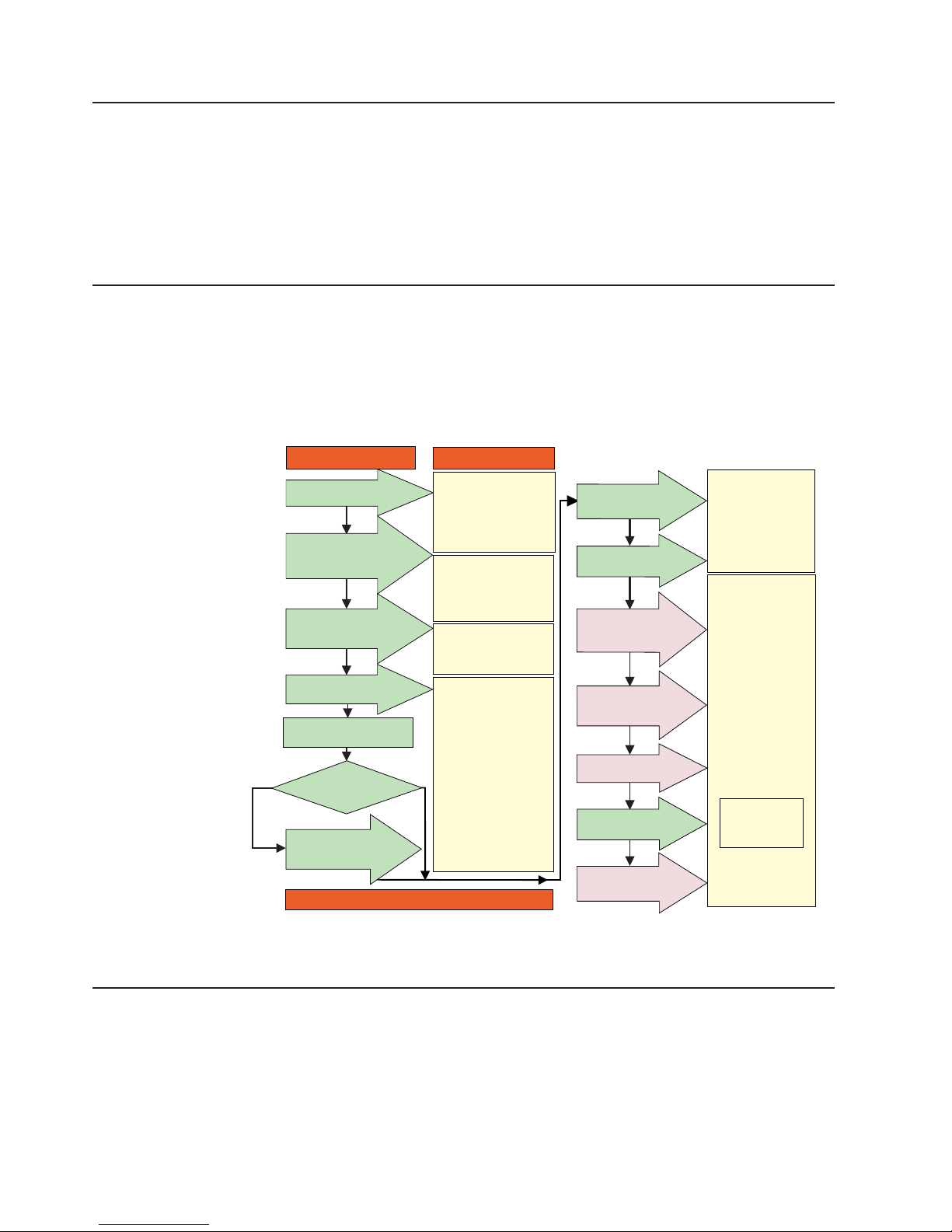
DS4000 installation process overview
The following flow chart gives an overview of the DS4000 hardware and the
DS4000 Storage Manager software installation process. Lined arrows in the flow
chart indicate consecutive steps in the hardware and software installation process.
Labeled arrows indicate which current documents provide detailed information about
those steps.
Install Process Documentation
Plan installation
Connect Power and
Start Server
DS4000 Storage Server
Installation Guide
Complete SM SW
Installation
Configure Storage
Hardware
Online Help
Configure Storage
Subsystems on Host
Verify Server
operation w/ LEDs
Prepare for
Installation of
SM Software
Install and Verify
SM SW on Host and
Workstation
* FC Planning and
Integration: User's Guide
and Svc Info
DS4000 Storage Manager
Concepts Guide
DS4000 Storage Exp Units
Install and User's Guides
DS4000 Fibre Channel
Storage Server
Installation Guides
Fibre Channel Cabling
Instructions
DS4000 and HBA Install
and User's Guides
DS4000 Storage Svr
Installation Guide
DS4000 RAID Controller
Enclosure Unit Install
and User's Guide
Copy Services
User's Guide
DS4000 Storage Manager
DS4000 Storage
Manager Installation
and Support
OS Guides
DS4000 Hardware
Maintenance Manual
DS4000 Problem
Determination Guide
Out-of-Band
In-Band
Make FC Connections
SET Link Speed
(1GB or 2GB)
Install Storage
Server/RAID Controller
Enclosure(s) in Rack
Install Network
Hardware; Prep are
Network Connection
Install Storage
Expansion Unit(s)
Determine
Management
Method
* For pSeries Server and 6227 or 6228 HBA use only
sj001046
DS4000 Storage Server publications
The following tables present an overview of the DS4500, DS4400, DS4300 Fibre
Channel, and DS4100 SATA Storage Server product libraries, as well as other
related documents. Each table lists documents that are included in the libraries and
what common tasks they address.
Figure 1. Installation process flow by current publications
xviii IBM TotalStorage DS4500 Fibre Channel Storage Server: User’s Guide
Page 21

You can access the documents listed in these tables at one of the following Web
sites:
www.ibm.com/servers/storage/support/disk/
www.ibm.com/shop/publications/order/
DS4500 storage server library
Table 2 associates each document in the DS4500 (previously FAStT900) storage
server library with its related common user tasks.
Table 2. TotalStorage DS4500 Fibre Channel Storage Server document titles by user tasks
Title User Tasks
Planning Hardware
Installation
Software
Installation
Configuration Operation and
Administration
Diagnosis and
Maintenance
IBM TotalStorage
DS4500 Installation
and Support Guide,
GC26-7727
U U U
IBM TotalStorage
DS4500 Fibre
Channel Cabling
Instructions,
GC26-7729
U U
IBM TotalStorage
DS4500 Storage
Server User’s
Guide, GC26-7726
U U U
IBM TotalStorage
DS4500 Rack
Mounting
Instructions,
GC26-7728
U U
About this document xix
Page 22

DS4400 storage server library
Table 3 associates each document in the DS4400 (previously FAStT700) storage
server library with its related common user tasks.
Table 3. TotalStorage DS4400 Fibre Channel Storage Server document titles by user tasks
Title User Tasks
Planning Hardware
Installation
Software
Installation
Configuration Operation and
Administration
Diagnosis and
Maintenance
IBM DS4400 Fibre
Channel Storage
Server User’s
Guide, GC26-7730
U U U U U
IBM DS4400 Fibre
Channel Storage
Server Installation
and Support Guide,
GC26-7731
U U U U
IBM DS4400 Fibre
Channel Cabling
Instructions,
GC26-7732
U U
xx IBM TotalStorage DS4500 Fibre Channel Storage Server: User’s Guide
Page 23

DS4300 storage server library
Table 4 associates each document in the DS4300 (previously FAStT600) storage
server library with its related common user tasks.
Table 4. TotalStorage DS4300 Fibre Channel Storage Server document titles by user tasks
Title User Tasks
Planning Hardware
Installation
Software
Installation
Configuration Operation and
Administration
Diagnosis and
Maintenance
IBM TotalStorage
DS4300 Fibre
Channel Storage
Server Installation
and User’s Guide,
GC26-7722
U U U
IBM TotalStorage
DS4300 Rack
Mounting
Instructions,
GC26-7724
U U
IBM TotalStorage
DS4300 Fibre
Channel Cabling
Instructions,
GC26-7725
U U
IBM TotalStorage
DS4300 SCU Base
Upgrade Kit,
GC26-7740
U U
IBM TotalStorage
DS4300 SCU Turbo
Upgrade Kit,
GC26-7741
U U
IBM TotalStorage
DS4300 Turbo
Models 6LU/6LX
Upgrade Kit,
GC26-7723
U U
About this document xxi
Page 24

DS4100 storage server library
Table 5 associates each document in the DS4100 (previously FAStT100) storage
server library with its related common user tasks.
Table 5. TotalStorage DS4100 SATA Storage Server document titles by user tasks
Title User Tasks
Planning Hardware
Installation
Software
Installation
Configuration Operation and
Administration
Diagnosis and
Maintenance
IBM TotalStorage
DS4100 Installation,
User’s and
Maintenance Guide,
GC26-7733
U U U U U
IBM TotalStorage
DS4100 Cabling
Guide, 24P8973
U
xxii IBM TotalStorage DS4500 Fibre Channel Storage Server: User’s Guide
Page 25

DS4000 Storage Manager Version 9 publications
Table 6 associates each document in the DS4000 Storage Manager (previously
FAStT Storage Manager) library with its related common user tasks.
Table 6. TotalStorage DS4000 Storage Manager Version 9 titles by user tasks
Title User tasks
Planning Hardware
installation
Software
installation
Configuration Operation and
administration
Diagnosis and
maintenance
IBM TotalStorage
DS4000 Storage
Manager Version 9
Installation and
Support Guide for
Windows
2000/Server 2003,
NetWare, ESX
Server, and Linux,
GC26-7706
U U U
IBM TotalStorage
DS4000 Storage
Manager Version 9
Installation and
Support Guide for
AIX, UNIX, Solaris
and Linux on
POWER,
GC26-7705
U U U
IBM TotalStorage
DS4000 Storage
Manager Version 9
Copy Services
User’s Guide,
GC26-7707
U U U U
IBM TotalStorage
DS4000 Storage
Manager Version 9
Concepts Guide,
GC26-7734
U U U U U U
About this document xxiii
Page 26

Other DS4000 and DS4000-related documents
Table 7 associates each of the following documents with its related common user
tasks.
Table 7. TotalStorage DS4000 and DS4000–related document titles by user tasks
Title User Tasks
Planning Hardware
Installation
Software
Installation
Configuration Operation and
Administration
Diagnosis and
Maintenance
IBM Safety
Information,
P48P9741
U
IBM TotalStorage
DS4000 Quick Start
Guide, GC26-7738
U U
IBM TotalStorage
DS4000 Hardware
Maintenance
Manual,GC26-7702
U
IBM TotalStorage
DS4000 Problem
Determination
Guide, GC26-7703
U
IBM Fibre Channel
Planning and
Integration: User’s
Guide and Service
Information,
SC23-4329
U U U U
IBM TotalStorage
DS4000 FC2-133
Host Bus Adapter
Installation and
User’s Guide,
GC26-7736
U U
IBM TotalStorage
DS4000 FC2-133
Dual Port Host Bus
Adapter Installation
and User’s Guide,
GC26-7737
U U
IBM TotalStorage
DS4000 Fibre
Channel and Serial
ATA Intermix
Premium Feature
Installation Overview
GC26-7713
U U U U
Fibre Channel
Solutions - IBM
DS4000 EXP500
Installation and
User’s Guide,
59p5637
U U U U U
xxiv IBM TotalStorage DS4500 Fibre Channel Storage Server: User’s Guide
Page 27

Table 7. TotalStorage DS4000 and DS4000–related document titles by user tasks (continued)
Title User Tasks
Planning Hardware
Installation
Software
Installation
Configuration Operation and
Administration
Diagnosis and
Maintenance
IBM TotalStorage
DS4000 EXP700
and EXP710
Storage Expansion
Enclosures
Installation, User’s,
and Maintenance
Guide, GC26-7735
U U U U U
IBM TotalStorage
DS4000 Hard Drive
and Storage
Expansion
Enclosures
Installation and
Migration Guide,
GC26-7704
U U
IBM DS4000
Management Suite
Java User’s Guide,
32P0081
U U
IBM Netfinity
®
Fibre
Channel Cabling
Instructions,
19K0906
U
IBM Fibre Channel
SAN Configuration
Setup Guide,
25P2509
U U U U
How this document is organized
Chapter 1, “Introduction,” on page 1 introduces the DS4500 Storage Server and its
primary components.
Chapter 2, “Operating the DS4500 Storage Server,” on page 19 describes the tasks
required to operate the DS4500 Storage Server.
Chapter 3, “Replacing the DS4500 Storage Server components,” on page 43
describes how to service and replace components of the DS4500 Storage Server.
“Accessibility,” on page 67 provides information about DS4000 Storage Manager
accessibility features.
“Notices” on page 69 provides product notices.
About this document xxv
Page 28

Notices and statements in this document
The caution and danger statements that this document uses also appear in the
multilingual Safety Information document provided with your DS4500 Storage
Server. Each caution and danger statement is numbered for easy reference to the
corresponding statements in the safety document.
This document uses the following types of notices and statements:
v Note: These notices provide important tips, guidance, or advice.
v Important: These notices provide information or advice that might help you avoid
inconvenient or problem situations.
v Attention: These notices indicate possible damage to programs, devices, or
data. An attention notice is placed just before the instruction or situation in which
damage could occur.
v Caution: These statements indicate situations that can be potentially hazardous
to you. A caution statement is placed just before the description of a potentially
hazardous procedure step or situation.
v Danger: These statements indicate situations that can be potentially lethal or
extremely hazardous to you. A danger statement is placed just before the
description of a potentially lethal or extremely hazardous procedure step or
situation.
Getting information, help, and service
If you need help, service, or technical assistance or just want more information
about IBM products, you will find a wide variety of sources available from IBM to
assist you. This section contains information about where to go for additional
information about IBM and IBM products, what to do if you experience a problem
with your IBM Eserver xSeries
®™
or IntelliStation
®
system, and whom to call for
service, if it is necessary.
Before you call
Before you call, make sure that you have taken these steps to try to solve the
problem yourself:
v Check all cables to make sure that they are connected.
v Check the power switches to make sure that the system is turned on.
v Use the troubleshooting information in your system documentation and use the
diagnostic tools that come with your system.
v Check for technical information, hints, tips, and new device drivers at the
following Web site:
www.ibm.com/servers/storage/support/disk/
v Use an IBM discussion forum on the IBM Web site to ask questions.
You
can solve many problems without outside assistance by following the
troubleshooting procedures that IBM provides in the online help or in the documents
that are provided with your system and software. The information that comes with
your system also describes the diagnostic tests that you can perform. Most xSeries
and IntelliStation systems, operating systems, and programs come with information
that contains troubleshooting procedures and explanations of error messages and
error codes. If you suspect a software problem, see the information for the
operating system or program.
xxvi IBM TotalStorage DS4500 Fibre Channel Storage Server: User’s Guide
Page 29

Using the documentation
Information about the xSeries or IntelliStation system and preinstalled software, if
any, is available in the documents that come with your system. This includes printed
documents, online documents, readme files, and help files. See the troubleshooting
information in your system documentation for instructions on how to use the
diagnostic programs. The troubleshooting information or the diagnostic programs
might tell you that you need additional or updated device drivers or other software.
Web sites
IBM maintains pages on the World Wide Web where you can get the latest
technical information and download device drivers and updates.
v For DS4000 information, go to the following Web site:
www.ibm.com/servers/storage/support/disk/
The support page has many sources of information and ways for you to solve
problems, including:
– Diagnosing problems using the IBM Online Assistant
– Downloading the latest device drivers and updates for your products
– Viewing frequently asked questions (FAQ)
– Viewing hints and tips to help you solve problems
– Participating in IBM discussion forums
– Setting up e-mail notification of technical updates about your products
v
You can order publications through the IBM Publications Ordering System at the
following web site:
www.elink.ibmlink.ibm.com/public/applications/publications/cgibin/pbi.cgi/
v For the latest information about IBM xSeries products, services, and support, go
to the following Web site:
www.ibm.com/eserver/xseries/
v For the latest information about IBM pSeries
®
products, services, and support, go
to the following Web site:
www.ibm.com/eserver/pseries/
v For the latest information about the IBM IntelliStation information, go to the
following Web site:
www-132.ibm.com/content/home/store_IBMPublicUSA/
en_US/IntelliStation_workstations.html
v For the latest information about operating system and HBA support, clustering
support, SAN fabric support, and Storage Manager feature support, see the
TotalStorage DS4000 Interoperability Matrix at the following Web site:
www.ibm.com/servers/storage/disk/ds4000/interop-matrix.html
Software service and support
Through IBM Support Line, for a fee you can get telephone assistance with usage,
configuration, and software problems with xSeries servers, IntelliStation
workstations, and appliances. For information about which products are supported
by Support Line in your country or region, go to the following Web site:
www.ibm.com/services/sl/products/
For more information about the IBM Support Line and other IBM services, go to the
following Web sites:
v www.ibm.com/services/
About this document xxvii
Page 30

v www.ibm.com/planetwide/
Hardware service and support
You can receive hardware service through IBM Integrated Technology Services or
through your IBM reseller, if your reseller is authorized by IBM to provide warranty
service. Go to the following Web site for support telephone numbers:
www.ibm.com/planetwide/
In the U.S. and Canada, hardware service and support is available 24 hours a day,
7 days a week. In the U.K., these services are available Monday through Friday,
from 9 a.m. to 6 p.m.
Fire suppression systems
A fire suppression system is the responsibility of the customer. The customer’s own
insurance underwriter, local fire marshal, or a local building inspector, or both,
should be consulted in selecting a fire suppression system that provides the correct
level of coverage and protection. IBM designs and manufactures equipment to
internal and external standards that require certain environments for reliable
operation. Because IBM does not test any equipment for compatibility with fire
suppression systems, IBM does not make compatibility claims of any kind nor does
IBM provide recommendations on fire suppression systems.
How to send your comments
Your feedback is important in helping us to provide the most accurate and
high-quality information. If you have comments or suggestions for improving this
publication, you can send us comments electronically by using these addresses:
v Internet: starpubs@us.ibm.com
v IBMLink
™
from U.S.A.: STARPUBS at SJEVM5
v IBMLink from Canada: STARPUBS at TORIBM
v IBM Mail Exchange: USIB3WD at IBMMAIL
You
can also mail your comments by using the Reader Comment Form in the back
of this manual or direct your mail to:
International Business Machines Corporation
Information Development
Dept. GZW
9000 South Rita Road
Tucson, AZ 85744–0001
U.S.A.
xxviii IBM TotalStorage DS4500 Fibre Channel Storage Server: User’s Guide
Page 31

Chapter 1. Introduction
The IBM TotalStorage DS4500 Fibre Channel Storage Server (referred to
throughout this book as the DS4500 Storage Server) is a high-performance unit that
provides dual, redundant array of independent disks (RAID) controllers and Fibre
Channel interfaces to both the host and drive channels.
DS4500 Storage Server overview
The DS4500 Storage Server (Machine type 1742, models 90U and 90X) supports
direct attachment of up to four hosts that contain two host adapters each, and is
designed to provide maximum host-side and drive-side redundancy. By using
external Fibre Channel switches in conjunction with the DS4500 Storage Server,
you can attach up to 64 hosts with two adapters each to a DS4500 Storage Server.
Each DS4500 Storage Server contains several removable components, called
customer replaceable units (CRUs), that you can access from either the front or
back of the unit. These CRUs include the battery, RAID controllers, storage server
fan, power supplies, fan and communications module, mini hubs, and Small
Form-Factor Pluggable (SFP) modules. The DS4500 Storage Server also has a
removable front bezel.
The DS4500 Storage Server functions with at least one external storage expansion
enclosure containing Fibre Channel or SATA hard drives. The DS4500 Storage
Server supports a maximum of 224 hard drives when the drives are configured
using IBM DS4000 EXP700, DS4000 EXP710, or DS4000 EXP100 storage
expansion enclosures. If the drives are configured using IBM FAStT EXP500
storage expansion enclosures only, a maximum of 220 hard drives are supported.
Attention:
v In order to attach DS4000 EXP100 or EXP710 storage expansion enclosures to
a DS4500 Storage Server, the DS4500 Storage Server controller firmware must
be at version 06.xx.xx.xx or higher. In addition, you must purchase the FC/SATA
Enclosure Intermix premium option to combine EXP100s with EXP700s or
EXP710s in the same DS4500 Storage Server configuration.
v The DS4500 controller units are not compatible with the DS4400 or FAStT500
controller units. The DS4500 controller units are keyed to prevent them from
being mistakenly inserted in the non-supported storage server units. Do not force
fit the controller units or the backplane might be damaged.
Product updates
Important
In order to keep your system up to date with the latest firmware and other
product updates, use the information below to register and use the My
support web site.
Download the latest version of the DS4000 Storage Manager host software and the
any appropriate DS4000 product series firmware at the time of the initial installation
and when product updates become available.
To be notified of important product updates, you must first register at the IBM
Support and Download Web site:
© Copyright IBM Corp. 2005 1
Page 32

www.ibm.com/support/us/
Go to the Personalized Support section of the web page and click My support.
On the next page, if you have not already done so, register to use the site by
clicking register now.
Perform the following steps to receive product updates:
1. After you have registered, type your user ID and password to log into the site.
The My support page opens.
2. Click add products. Using the pull downs in the Products area, select Storage
→ Computer Storage → Disk Storage Systems → TotalStorage DS4000
Midrange Disk Systems & FAStT Stor Srvrs.
3. Place a check in the box for the machine type of your DS4000 series product,
as well as any other attached DS4000 series product(s) for which you would like
to receive information. Select Add products. The My support page reopens.
4. Select Subscribe to email. In the Documents area on the next page, use the
pull down and select Storage.
5. On the next page, place a check in the following boxes:
a. Please send these documents by weekly email
b. Downloads and drivers
c. Flashes
and
any others you may be interested in, and then click Update.
Front view
Figure 2 on page 3 shows the bezel. The bezel is a removable front cover with
holes for viewing the status lights and for boosting air circulation.
Note: The illustrations in this document might differ slightly from your hardware.
2 IBM TotalStorage DS4500 Fibre Channel Storage Server: User’s Guide
Page 33

GS000031
Removable bezel
DS4500
Figure 3 shows the following components on the DS4500 Storage Server without
the front bezel:
v Storage server fan - A removable unit that contains two cooling fans and
indicator lights
v Battery - A removable unit that contains the cache battery for the controllers,
battery charger circuitry, and status indicator lights
v Controllers - Two removable units that each contain one RAID controller with 1
Gb cache memory and status indicator lights
Back view
Figure 4 on page 4 shows the DS4500 Storage Server back view and the following
components:
v Host-side and drive-side mini hubs - Up to eight removable mini hubs with
indicator lights. You can insert SFP modules into the mini hubs and connect
fiber-optic host and drive interface cables to the DS4000 Storage Server. (The
standard DS4500 configuration includes two host and two drive mini hubs.)
v Power supplies - Two removable units that each contain a power supply and an
indicator light.
Figure 2. IBM TotalStorage DS4500 Fibre Channel Storage Server front bezel
Figure
3. IBM TotalStorage DS4500 Fibre Channel Storage Server front view
Chapter 1. Introduction 3
Page 34

v Fan and communications module - A removable unit that contains the power
supply cooling fans, an indicator light, and Ethernet ports.
Fibre Channel connections
When fully configured, the back of the DS4500 Storage Server can accommodate
up to four host-side and four drive-side mini hubs. Each mini hub is a single,
removable unit that provides the Fibre Channel interface between a DS4500
Storage Server, host computers, and drives. Each mini hub has two SFP module
ports. An SFP module is inserted into a mini-hub port. Figure 5 shows the Fibre
Channel components.
Figure 4. IBM TotalStorage DS4500 Fibre Channel Storage Server - back view
Figure
5. Fibre Channel interface connections
4 IBM TotalStorage DS4500 Fibre Channel Storage Server: User’s Guide
Page 35

The DS4500 Storage Server uses fiber-optic cables to connect to other Fibre
Channel devices. The fiber-optic cables that you need depend on the type of optical
connectors in the device to which you are connecting the DS4500 Storage Server. If
the device uses SFP modules or optical interface connectors, then you must use
LC-LC Fibre Channel cables. If the device uses Gigabit Interface Converters
(GBICs) as the optical interface connector, you must use LC-LC Fibre Channel
cables and LC-SC Fibre Channel cable adapters (Part number 19K1250) to connect
to the DS4500 Storage Server.
Handling fiber-optic cables
Before you use fiber-optic cables, read the following precautions.
Attention: To avoid damage to your fiber-optic cables, follow these guidelines:
v Do not route the cable along a folding cable-management arm.
v When attaching to a device on slide rails, leave enough slack in the cable so that
it does not bend to a radius of less than 38 mm (1.5 in.) when extended or
become pinched when retracted.
v Route the cable away from places where it can be damaged by other devices in
the rack cabinet.
v Do not use plastic cable ties in place of the provided cable straps.
v Do not overtighten the cable straps or bend the cables to a radius of less than 38
mm (1.5 in.).
v Do not put excess weight on the cable at the connection point. Be sure that the
cable is well supported.
Using LC-LC Fibre Channel cables
The LC-LC Fibre Channel cable is a fiber-optic cable that is used to connect into
one of the following devices:
v SFP module installed in a DS4500 Storage Server mini hub
v SFP module installed in an IBM Fibre Channel switch
v SFP module installed in an IBM DS4000 EXP700 or DS4000 EXP710 storage
expansion enclosure
v SFP module installed in an IBM DS4000 EXP100 storage expansion enclosure
v Optical interface connector on an IBM DS4000 FC-2 Host Bus Adapter (part
number 19K1246), IBM DS4000 single port FC2-133 Host Bus Adapter (part
number 24P0960), or dual port FC2-133 Host Bus Adapter (part number
24P8053)
Figure
6 on page 6 shows an LC-LC Fibre Channel cable.
Chapter 1. Introduction 5
Page 36

The following sections provide the procedures for properly connecting and removing
an LC-LC Fibre Channel cable.
Note: If you are connecting a DS4500 Storage Server to a FAStT EXP500 storage
expansion enclosure or to an IBM DS4000 host adapter, you must also use
a Fibre Channel cable adapter. For more information about how to use the
LC-SC Fibre Channel cable adapter, see “Using LC-SC Fibre Channel cable
adapters” on page 9.
Connecting an LC-LC Fibre Channel cable to an SFP module
To connect an LC-LC Fibre Channel cable to an SFP module, complete the
following steps.
Statement 3:
CAUTION:
When laser products (such as CD-ROMs, DVD drives, fiber optic devices, or
transmitters) are installed, note the following precautions:
v Do not remove the covers. Removing the covers of the laser product could
result in exposure to hazardous laser radiation. There are no serviceable
parts inside the device.
v Use of controls or adjustments or performance of procedures other than
those specified herein might result in hazardous radiation exposure.
DANGER
Some
laser products contain an embedded Class 3A or Class 3B laser
diode. Note the following precautions. Laser radiation when open. Do not
stare into the beam, do not view directly with optical instruments, and
avoid direct exposure to the beam.
1. Read the information in “Handling fiber-optic cables” on page 5.
Figure 6. LC-LC Fibre Channel cable
6 IBM TotalStorage DS4500 Fibre Channel Storage Server: User’s Guide
Page 37

2. If necessary, remove the protective cap from the SFP module, as shown in
Figure 49 on page 62. Save the protective cap for future use.
3. Remove the two protective caps from one end of the LC-LC cable as shown in
Figure 7. Save the protective caps for future use.
4. Carefully insert that same end of the LC-LC cable into an SFP module that is
installed in a DS4500 Storage Server mini hub. The cable connector is keyed to
ensure it is inserted into the SFP module correctly. While you hold the
connector, push in the connector until it clicks into place.
Figure 7. Removing the fiber-optic cable protective caps
Figure
8. Inserting an LC-LC Fibre Channel cable into an SFP module
Chapter 1. Introduction 7
Page 38

Figure 9 shows an LC-LC Fibre Channel cable that connects into an SFP
module that is installed in a DS4500 Storage Server mini hub.
5. Remove the two protective caps from the other end of the LC-LC cable, as
shown in Figure 7 on page 7. Save the protective caps for future use.
6. Connect the end of the LC-LC Fibre Channel cable to one of the following
devices:
v SFP module that is installed in an IBM Fibre Channel switch
v Optical interface connector on an IBM DS4000 FC-2 Host Bus Adapter (part
number 19K1246)
v LC-SC Fibre Channel cable adapter (For information about how to use an
LC-SC cable adapter, see “Using LC-SC Fibre Channel cable adapters” on
page 9.)
Removing an LC-LC Fibre Channel cable from an SFP module
To remove an LC-LC Fibre Channel cable, perform the following steps:
Attention: To avoid damaging the LC-LC cable or SFP module, make sure you
press and hold the lever to release the latches as you remove the cable from the
SFP module.
1. On the end of the LC-LC cable that connects into the SFP module or host bus
adapter, press down and hold the lever to release the latches, as shown in
Figure 10 on page 9. Carefully pull on the connector to remove the cable from
the SFP module, (ensure that the levers are in the released position when you
remove the cable) as shown in Figure 11 on page 9. If you use the SFP module
with the pull tab, make sure you do not grasp the plastic tab when you remove
the cable.
Figure 9. Inserting an LC-LC Fibre Channel cable into an installed SFP module
8 IBM TotalStorage DS4500 Fibre Channel Storage Server: User’s Guide
Page 39

2. Replace the protective caps on the cable ends.
3. Replace the protective cap on the SFP module.
Using LC-SC Fibre Channel cable adapters
The LC-SC Fibre Channel Cable Adapter is a fiber-optic cable that you use to
connect the LC connector into one of the following devices that require SC
connectors:
v DS4000 host adapter (Part number 00N6881)
v FAStT EXP500 storage expansion enclosure (Machine type 3560)
v 1 Gb Fibre Channel switch (Machine type 2109)
v 1 Fibre Channel Managed hub (Machine type 3534)
Figure 10. LC-LC Fibre Channel Cable lever and latches
Figure
11 . Removing the LC-LC Fibre Channel cable
Chapter 1. Introduction 9
Page 40

Figure 12 shows an LC-SC Fibre Channel cable adapter.
The following sections provide the procedures for properly connecting and removing
an LC-SC Fiber Channel cable adapter.
Connecting an LC-SC cable to a device
To connect an LC-SC cable adapter to a device or LC-LC cable, complete the
following steps.
Statement 3:
CAUTION:
When laser products (such as CD-ROMs, DVD drives, fiber optic devices, or
transmitters) are installed, note the following precautions:
v Do not remove the covers. Removing the covers of the laser product could
result in exposure to hazardous laser radiation. There are no serviceable
parts inside the device.
v Use of controls or adjustments or performance of procedures other than
those specified herein might result in hazardous radiation exposure.
DANGER
Some
laser products contain an embedded Class 3A or Class 3B laser
diode. Note the following precautions. Laser radiation when open. Do not
stare into the beam, do not view directly with optical instruments, and
avoid direct exposure to the beam.
1. Read the information in “Handling fiber-optic cables” on page 5.
Figure 12. LC-SC Fibre Channel cable
10 IBM TotalStorage DS4500 Fibre Channel Storage Server: User’s Guide
Page 41

2. Connect an LC-LC cable to an SFP module in the DS4500 Storage Server mini
hub. For instructions, see “Connecting an LC-LC Fibre Channel cable to an SFP
module” on page 6.
3. Remove the two protective caps from the LC connector end of the LC-SC cable,
as shown in Figure 13. Save the protective caps for future use.
4. Carefully insert one end of an LC-LC cable into the LC connector end of the
LC-SC cable. Push in the connector until it clicks into place.
5. Connect the SC connector end of the LC-SC cable to one of the following
devices:
v Optical interface connector on an IBM DS4000 Host Bus Adapter (Part
number 00N6881)
v GBIC installed in a FAStT EXP500 storage expansion enclosure (Machine
type 3560)
v 1 Gb Fibre Channel switch (Machine type 2109)
v 1 Gb Fibre Channel managed hub (Machine type 3534)
Removing an LC-LC cable from an LC-SC cable adapter
To remove an LC-LC cable from an LC-SC cable adapter, perform the following
steps:
Figure 13. Removing the LC-SC cable adapter protective caps
Figure
14. LC-LC cable connected into the LC-SC cable adapter
Chapter 1. Introduction 11
Page 42

Attention: To avoid damaging the LC-LC cable, make sure you press and hold
the lever to release the latches while you remove the cable from an LC-SC cable
adapter. Ensure that both levers on the LC-LC cable are in the released position
when you remove the cable.
1. On the end of the cable that connects into the LC connector end of the LC-SC
cable adapter, press down and hold the lever to release the latches. Figure 15
shows the location of the lever and latches.
2. Carefully pull on the connector to remove it. Make sure you grasp the connector
and not the cable when you remove the LC-LC cable from the LC-SC cable
adapter, as shown in Figure 16.
3. Replace the protective caps on the cable ends.
Types of interface ports
The DS4500 Storage Server has the following types of interface ports:
v Host mini hub
v Drive mini hub
v Ethernet
The
host and drive mini-hub ports are used for data transfer between hosts or
storage expansion enclosures and RAID controllers in the DS4500 Storage Server.
Ethernet ports are available for storage subsystem-management. The DS4500
Figure 15. LC-LS Fibre Channel cable lever and latches
Figure
16. Removing the LC-LC Fibre Channel cable from an LC-SC Fibre Channel cable
adapter
12 IBM TotalStorage DS4500 Fibre Channel Storage Server: User’s Guide
Page 43

Storage Server interface ports are shown in Figure 17.
For more information about how to connect the DS4500 Storage Server and
storage expansion enclosures by using the host and drive interface ports, refer to
the IBM DS4500 Fibre Channel Storage Server Installation and Support Guide.
Host interface ports
The DS4500 Storage Server comes with host-side mini hubs 1 and 2 installed.
Each mini hub provides host loop connectivity and self-diagnostic features. Host
mini hubs connect to the controller in pairs. When fully configured, the DS4500
Storage Server can accommodate four host-side mini hubs, two per controller. Mini
hubs 1 and 3 connect to the top controller (Controller A) and mini hubs 2 and 4
connect to the bottom controller (Controller B), as shown in Figure 18. To ensure
redundancy, you must connect each host to both controllers through the appropriate
mini hub.
Drive interface ports
The DS4500 Storage Server comes with drive-side mini hubs 1 and 2 installed.
Each drive mini hub connects to Controller A and Controller B and represents a
single drive loop. The drive loops must be set up in pairs to support redundant drive
loop configurations (two data paths per storage expansion enclosure). DS4500
Storage Servers use only redundant drive-loop configurations. See Figure 19 on
page 14 for an illustration of the drive-side mini-hub interface ports.
Figure 17. DS4500 Storage Server interface ports
Figure
18. Host-side mini-hub interface ports
Chapter 1. Introduction 13
Page 44

The maximum number of storage expansion enclosures that can be connected per
pair of redundant drive loops depends on the IBM DS4000 storage expansion
enclosure models used. The following DS4000 storage expansion enclosure types
are supported by the DS4500 Storage Server:
v FAStT EXP500
v DS4000 EXP700
v DS4000 EXP710
v DS4000 EXP100
If the drives are configured using only DS4000 EXP700, EXP710, or EXP100
storage expansion enclosures, the DS4500 Storage Server supports a maximum of
224 hard drives.
If the drives are configured using only FAStT EXP500 storage expansion
enclosures, the DS4500 Storage Server supports a maximum of 220 hard drives.
Attention: In order to attach DS4000 EXP100 or DS4000 EXP710 storage
expansion enclosures to a DS4500 Storage Server, the DS4500 Storage Server
controller firmware must be at version 06.xx.xx.xx or higher. In addition, you must
purchase the FC/SATA Enclosure Intermix premium option to combine DS4000
EXP100s with DS4000 EXP700s or DS4000 EXP710s in the same DS4500 Storage
Server configuration.
For detailed information about how to cable the storage server and storage
expansion enclosures, see the IBM TotalStorage DS4500 Fibre Channel Storage
Server Installation and Support Guide and the DS4500 Fibre Channel Cabling
Instructions that come with the storage server.
Intermixing storage expansion enclosure models
Storage expansion enclosure models can be mixed in the same redundant drive
loop or the same pair of redundant drive loops. As described in the following
sections, you can intermix FAStT EXP500s and DS4000 EXP700s, and you can
also intermix DS4000 EXP100s, EXP710s, and EXP700s.
Figure 19. Drive-side mini-hub interface ports
14 IBM TotalStorage DS4500 Fibre Channel Storage Server: User’s Guide
Page 45

You cannot mix DS4000 EXP100s or DS4000 EXP710s with FAStT EXP500s in any
DS4000 storage server configuration. If a DS4000 EXP100 or DS4000 EXP710 is
attached to the DS4500 Storage Server in one drive loop, no FAStT EXP500s can
be present either in the same drive loop or in the other drive loop.
Note: This restriction exists because the FAStT EXP500 storage expansion
enclosure operates at 1 Gbps only, while the DS4000 EXP100 and DS4000
EXP710 storage expansion enclosures do not operate at 1 Gbps. The
DS4500 Storage Server does not support mixed drive loop speeds.
Intermixing FAStT EXP500s and DS4000 EXP700s: Yo u can intermix FAStT
EXP500 and DS4000 EXP700 storage expansion enclosure models in the same
redundant pair of drive loops.
Attention: If you are intermixing FAStT EXP500s and DS4000 EXP700s, it is
strongly recommended that you do not cable the FAStT EXP500 and DS4000
EXP700 storage expansion enclosure models in the same redundant drive loop
pair. Instead, you should cable the FAStT EXP500 storage expansion enclosures
together using one pair of redundant drive loops, and you should the DS4000
EXP700 storage expansion enclosures together using the other pair of redundant
drive loops.
Note:
You might need to purchase two additional drive mini hubs to implement this
cabling scheme.
If you are intermixing FAStT EXP500s and DS4000 EXP700s, your drive loop
configuration must meet the following requirements:
v The maximum Fibre Channel transfer speed in all of the DS4000 EXP700s must
be set to 1 Gbps because the maximum FC transfer speed of the IBM FAStT
EXP500 storage expansion enclosures is 1 Gbps. Otherwise, a drive channel
mini hub data rate mismatch error will be generated.
v The maximum Fibre Channel transfer speed in all the DS4500 Storage Server
drive-side mini hubs must be set to 1 Gbps.
Attention: If you change the DS4000 EXP700 storage expansion enclosure or
DS4500 Storage Server enclosure link speed setting, you must power-cycle the
storage server. See “Turning off the power” on page 23 and “Turning on the
power” on page 22 for the proper DS4000 configuration power-down and
power-up sequences. For more information, see the IBM TotalStorage DS4000
Hard Drive and Storage Expansion Enclosure Installation and Migration Guide.
If
you intermix FAStT EXP500s and DS4000 EXP700s within a single drive loop,
see Table 8 for the possible combinations of FAStT EXP500 and DS4000 EXP700
storage expansion enclosures per drive loop.
Table 8. Possible combinations of FAStT EXP500 and DS4000 EXP700 storage expansion
enclosures per drive loop
Number of FAStT
EXP500 units
Number of DS4000
EXP700 units
Total number of
storage expansion
enclosures
Total number of
drives
0 8 8 112
1 7 8 108
2 6 8 104
3 6 9 114
Chapter 1. Introduction 15
Page 46

Table 8. Possible combinations of FAStT EXP500 and DS4000 EXP700 storage expansion
enclosures per drive loop (continued)
Number of FAStT
EXP500 units
Number of DS4000
EXP700 units
Total number of
storage expansion
enclosures
Total number of
drives
4 5 9 110
5 4 9 106
6 3 9 102
7 3 10 112
8 2 10 108
9 1 10 104
10 0 10 100
11 0 11 110
Important: These large configurations are for capacity purposes and might not
provide the best performance.
For full details on the requirements for intermixing FAStT EXP500 and DS4000
EXP700 storage expansion enclosures, refer to the IBM TotalStorage DS4000
EXP700 and EXP710 Storage Expansion Enclosures Installation, User’s, and
Maintenance Guide. You can also refer to the IBM TotalStorage DS4000 Hard Drive
and Storage Expansion Enclosure Installation and Migration Guide.
Intermixing DS4000 EXP710s and DS4000 EXP700s: You can intermix DS4000
EXP710s and DS4000 EXP700s in the same drive loop with a DS4500 Storage
Server, but all DS4000 EXP710s must be grouped together.
Important
The requirements for intermixing DS4000 EXP710s and EXP700s state that all
DS4000 EXP710s in a redundant drive loop must be grouped together. IBM
does not support intermixed drive loop configurations in which all DS4000
EXP710s are not grouped together.
Attention: The minimum DS4000 EXP700 ESM firmware requirement for
intermixing DS4000 EXP710s and EXP700s is version 9326. Verify that the ESM
firmware for all DS4000 EXP700s is at version 9326 or higher before intermixing
DS4000 EXP700s with EXP710s.
In order to attach DS4000 EXP710 storage expansion enclosures to a DS4500
Storage Server, the DS4500 Storage Server controller firmware must be at version
06.xx.xx.xx or higher.
A fully configured DS4500 Storage Server supports a maximum of 16 IBM DS4000
EXP700 or EXP710 storage expansion enclosures (8 storage expansion enclosures
per drive-loop pair), or 224 drives, using dual pairs of redundant drive loops.
For full details on the requirements for intermixing DS4000 EXP710s and EXP700s,
refer to the IBM TotalStorage DS4000 EXP700 and EXP710 Storage Expansion
16 IBM TotalStorage DS4500 Fibre Channel Storage Server: User’s Guide
Page 47

Enclosures Installation, User’s, and Maintenance Guide . You can also refer to the
IBM TotalStorage DS4000 Hard Drive and Storage Expansion Enclosure Installation
and Migration Guide.
Intermixing DS4000 EXP100s with DS4000 EXP710s and EXP700s: Yo u can
intermix DS4000 EXP100s SATA storage expansion enclosures with either DS4000
EXP710s, DS4000 EXP700s, or both EXP710s and EXP700s, in the same pair of
redundant drive loops with a DS4500 Storage Server, but all DS4000 EXP710s
must be grouped together.
Important
The requirements for intermixing DS4000 EXP100s with either DS4000
EXP710s, DS4000 EXP700s, or both EXP710s and EXP700s, state that all
DS4000 EXP710s in the same pair of redundant drive loops must be grouped
together. IBM does not support intermixed drive loop configurations in which
all DS4000 EXP710s are not grouped together.
In order to attach DS4000 EXP100 or EXP710 storage expansion enclosures to a
DS4500 Storage Server, the DS4500 Storage Server controller firmware must be at
version 06.xx.xx.xx or higher. In addition, you must purchase the FC/SATA
Enclosure Intermix premium option to combine EXP100s with EXP700s or EXP710s
in the same DS4500 Storage Server configuration.
For more information on the cabling requirements and best practices for intermixing
EXP100s with EXP700s or EXP710s in the same DS4500 Storage Server
configuration, refer to the IBM TotalStorage DS4000 Fibre Channel and Serial ATA
Intermix Premium Feature Installation Overview that ships with the FC/SATA
Enclosure Intermix premium feature. Yo u can also refer to the IBM TotalStorage
DS4000 Hard Drive and Storage Expansion Enclosure Installation and Migration
Guide.
Attention: The minimum DS4000 EXP100 ESM firmware requirement for
intermixing DS4000 EXP100s with DS4000 EXP710s or EXP700s is version 9554.
Before intermixing DS4000 EXP100s with DS4000 EXP700s or EXP710s, you must
verify that the ESM firmware for all DS4000 EXP100s is at version 9554 or higher.
As discussed in “Intermixing DS4000 EXP710s and DS4000 EXP700s” on page 16,
you must also verify that the ESM firmware for all DS4000 EXP710s and EXP700s
is at version 9326 or higher.
A fully configured DS4500 Storage Server supports a maximum of 16 IBM DS4000
EXP700, EXP710, or EXP100 storage expansion enclosures (8 storage expansion
enclosures per drive-loop pair), or 224 drives, using dual pairs of redundant drive
loops.
Ethernet interface ports
There are two Ethernet interface ports, one for each controller (Controller A and
Controller B). Use the Ethernet ports to directly manage storage subsystems.
Chapter 1. Introduction 17
Page 48

Figure 20 shows the location of the interface ports.
Figure 20. Ethernet interface ports
18 IBM TotalStorage DS4500 Fibre Channel Storage Server: User’s Guide
Page 49

Chapter 2. Operating the DS4500 Storage Server
This chapter describes the tasks required to operate the DS4500 Storage Server.
Best practices guidelines
To ensure optimal operation of your system, always follow these best practices
guidelines:
v Back up the data on your storage drives periodically.
v To maintain power redundancy, plug the DS4500 storage server’s right and the
left power supplies into two independent external power circuits through ac
distribution units inside a rack cabinet or directly into external receptacles.
Similarly, the right and left power supplies of the DS4000 storage expansion
enclosures attached to the DS4500 storage server should be plugged into the
same two independent external power circuits as the DS4500. This ensures that
the DS4500 storage server and all its attached storage expansion enclosures will
have power if only one power circuit is available. In addition, having all the right
or all the left power supplies plug into the same power circuit enables the
components in the storage subsystem to power on simultaneously during an
unattended restoration of power.
v Before any planned system shutdown or after any system additions, removals, or
modifications (including logical drive creations, storage partitioning definitions,
hardware changes, and so on), save the storage subsystem profile as explained
in the DS4000 Storage Manager guide for your operating system. Save the
profile in a location other than the logical drives created for the DS4500 storage
server.
v Ensure that your system is in an optimal state before you shut it down. Never
turn the power off if any fault light is lit; be sure to resolve any error conditions
before you shut down the system.
v During any maintenance or attended power-up procedure, carefully follow the
sequences listed in “Turning on the power” on page 22 and “Turning off the
power” on page 23 for the proper DS4000 configuration power-down and
power-up sequences. Check that each component of the subsystem is
powered-on in the proper order during this entire power-up procedure to ensure
the controller will be able to optimally access all of your storage subsystems.
v A storage system in an optimal state should recover automatically from an
unexpected shutdown and unattended simultaneous restoration of power to
system components. After power is restored, call IBM support if any of the
following conditions occur:
– The storage subsystem logical drives and arrays are not displayed in the
DS4000 Storage Manager graphical user interface (GUI).
– The storage subsystem logical drives and arrays do not come online.
– The storage subsystem logical drives and arrays seem to be degraded.
v
Using the DS4000 Storage Manager client, save the DS4000 subsystem
configuration profile to a disk that is not affected every time you make changes
(such as logical drive creation or modification, or storage partitioning changes) to
the DS4000 subsystem configuration.
Tasks overview
Perform the tasks shown in Table 9 on page 20 to maintain the DS4500 Storage
Server after you install it.
© Copyright IBM Corp. 2005 19
Page 50

Table 9. Tasks overview
Task Description See
Accessing the DS4500 Storage
Server components and indicator
lights
To access the controller CRUs,
battery, storage server fan, and
indicator lights, remove the DS4500
Storage Server bezel.
“Removing and replacing the front
bezel to access the DS4000 Storage
Server components”
Turning on or off the power The DS4500 Storage Server usually
runs continuously. However, you might
need to turn off the power to move the
DS4500 Storage Server or to perform
maintenance procedures.
“Turning on the power” on page 22
and “Turning off the power” on page
23
Monitoring DS4500 Storage Server
status through software
Run the storage-management
software continuously. This software
checks the storage subsystem for
failures and displays messages that
indicate the types of failures and the
recovery procedures.
“Monitoring status through software”
on page 25
Checking fault indicator lights for
component failures
Component failures are indicated by
lights on the front and back of the
DS4500 Storage Server and are
monitored by the
storage-management software.
Note: The indicator lights identify
problems with the DS4500 Storage
Server components, but you might
need more information to thoroughly
diagnose and repair the unit.
Therefore, it is important to use the
storage-management software to
continuously monitor the status of the
DS4500 Storage Server.
“Checking the indicator lights” on page
26
Restoring power after a power supply
shutdown
When the DS4500 Storage Server
shuts down because of a power
supply overtemperature condition,
take special care restarting it.
“Overtemperature condition and power
supply shutdown” on page 37
Checking the battery service date Periodically check the battery service
date information. Replace the battery
whenever it fails to hold a charge or
every three years.
Note: Using the DS4500 Storage
Server in a hot environment (above
35° C or 95° F), lowers the battery life
expectancy. Environmental conditions
that are not in the specified range are
not supported.
“Checking the battery service date” on
page 38
Preparing to move the DS4500
Storage Server
You might need to move the DS4500
Storage Server to a new location or
remove the chassis from its rack
cabinet.
“Preparing to move the DS4500
Storage Server” on page 39
Removing and replacing the front bezel to access the DS4000 Storage
Server components
To access the controller blades, battery, storage server fan, and indicator lights, you
must remove the DS4500 Storage Server bezel, as shown in Figure 21 on page 21.
20 IBM TotalStorage DS4500 Fibre Channel Storage Server: User’s Guide
Page 51

Attention: Pulling the cover out too far can damage the plastic hooks at the top.
To avoid damaging the hooks, place the DS4500 Storage Server on a flat surface.
Be sure the front of the DS4500 Storage Server extends beyond the edge
approximately 5 cm (2 in.).
1. Carefully pull the bottom of the bezel out to release the pins. Then slide the
bezel down as shown in Figure 21.
2. To replace the bezel, slip the top edge of the bezel under the lip on the chassis,
then push the bottom of the bezel until the pins snap into the mounting holes,
as shown in Figure 22 on page 22.
Figure 21. Removing the DS4500 Storage Server bezel
Chapter 2. Operating the DS4500 Storage Server 21
Page 52

DS4500 bezel
GS000034
Turning on the power
Important: Yo u must turn on the storage expansion enclosures before you turn on
the DS4500 Storage Server. The controllers might not recognize the correct
configuration if you turn on the hard disk drives after the DS4500 Storage Server.
Always wait at least 30 seconds between the time you turn off a power switch and
the time you turn on the power.
Turn on the power to each device in the following order:
v Supporting devices
v Storage expansion enclosures
v DS4500 Storage Server
v Host
If you are restoring power to the DS4500 Storage Server after an emergency
shutdown or power outage, go to “Overtemperature condition and power supply
shutdown” on page 37.
Use the following procedure to turn on the connected devices and the DS4500
Storage Server:
1. Turn on the power to the supporting devices (for example, Ethernet switches,
Fibre Channel switches, and management stations).
2. Turn on the storage expansion enclosure. The controllers might not recognize
the correct configuration if the drives are powered up after the storage server.
For instructions on turning on the storage expansion enclosures, refer to the
storage expansion enclosure documentation.
3. Turn on the power to the DS4500 Storage Server, as follows:
Figure 22. Replacing the DS4500 Storage Server bezel
22 IBM TotalStorage DS4500 Fibre Channel Storage Server: User’s Guide
Page 53

a. Verify that all communication and power cables are plugged into the back of
the DS4500 Storage Server and to a properly grounded ac electrical outlet.
b. Turn on the power supply switches on the back of the DS4500 Storage
Server (see Figure 23). You must turn on both power-supply switches to
take advantage of the redundant power supplies.
c. Use the storage-management software and the Fault indicator lights to
check the overall status of the DS4500 Storage Server and its components.
See “Checking the indicator lights” on page 26.
4.
Depending on the type of operating system on the host server, perform either a
server power cycle, a server restart, or a rescan for hardware on the host
server.
Turning off the power
Attention: The DS4500 Storage Server is designed to run continuously, 24 hours
a day. Except in an emergency, never turn off the power even if any DS4500
Storage Server fault indicator lights are lit. Use the proper troubleshooting or
servicing procedure to correct the fault before you turn off the power. This measure
ensures that the DS4500 Storage Server powers up correctly later. Also do not
power off the storage server to reset it. Use the Reset Controller menu function in
the Storage Manager Client program instead.
Figure 23. Connecting the power cords and power switch locations
Chapter 2. Operating the DS4500 Storage Server 23
Page 54

Statement 5:
CAUTION:
The power control button on the device and the power switch on the power
supply do not turn off the electrical current supplied to the device. The device
also might have more than one power cord. To remove all electrical current
from the device, ensure that all power cords are disconnected from the power
source.
1
2
Use the following procedure to turn off power to the DS4500 Storage Server:
1. Make sure that all amber fault indicator lights on the DS4500 Storage Server
are off. If any fault indicator lights are on, use the storage-management software
to determine the status of the system components and correct any problems
before you turn off the power. For more information, see “Monitoring status
through software” on page 25 and “Checking the indicator lights” on page 26.
2. Perform any required procedures that are indicated by the operating system
software.
3. Prepare the DS4500 Storage Server for shutdown, as follows:
a. Stop all I/O activity to the DS4500 Storage Server and attached storage
expansion enclosures.
Note: If a parity check is in progress, it might take a long time for the drive
indicator lights to stop blinking.
b. Use the operating system software to disconnect the DS4500 Storage
Server logical drives from the host before you power off the storage server.
c. Make sure that the fast write cache indicator light on each DS4500 Storage
Server front panel and all drive active indicator lights on each storage
expansion enclosure front panel are off (not blinking).
Attention: To turn off all power to the storage server, you must turn off both
power supply switches and disconnect both power cords. Use the procedure in
step 4 for the proper shutdown sequence.
4. Turn off the power to the DS4500 Storage Server or turn off the power to each
device using the following shutdown sequence.
a. Turn off power to the host before you turn off the power to the storage
server. If the host must stay powered on to support an existing network,
refer to the operating system documentation for information about
disconnecting the storage server logical drives from the host before the
storage server is powered off.
b. Turn off power to the storage server before you turn off power to the storage
expansion enclosures. Turn off both power supply switches on the back of
the storage server. See Figure 23 on page 23.
24 IBM TotalStorage DS4500 Fibre Channel Storage Server: User’s Guide
Page 55

c. Instead of turning off the power to other supporting devices ( for example,
management stations, Fibre Channel switches, or Ethernet switches),
disconnect the communications cables to the supporting devices.
Monitoring status through software
To monitor DS4500 Storage Server status, always run the DS4500 Storage
Manager software and check it frequently. Be sure to enable the management alerts
that you need. The DS4500 Storage Manager software provides the best way to
diagnose and repair DS4500 Storage Server failures. This software can help you:
v Determine the nature of a failure
v Locate a failed component
v Provide recovery procedures to repair a failure
Although the DS4500 Storage Server has fault indicators, these lights are summary
indicators and might not identify the specific component that has failed or needs
replacing, or which type of recovery procedure you must perform. In some cases
(such as loss of redundancy in DS4500 Storage Server drive loops), the fault light
does not come on. Only the storage-management software can detect the failure.
Recovering from a DS4500 Storage Server failure might require you to perform
procedures other than replacing the component. The DS4500 Storage Manager
software gives these procedures when you are using the Recovery Guru menu.
Note: Always follow the software recovery procedures to prevent data loss.
For more information about the DS4500 Storage Manager software, refer to the
Online help or publications that are appropriate for your operating system (see
“About this document” on page xvii for a list of publications).
Firmware updates
In order to ensure the optimal operation of the DS4500 storage server and its
attached storage expansion enclosures, the storage expansion enclosure ESM
firmware, the DS4500 storage server controller firmware, the hard drive firmware,
and the NVSRAM (for controllers only) must be up to date. Go to the following Web
site to get the latest updates.
www.ibm.com/servers/storage/support/disk/
Apply the necessary updates before configuring the DS4500 arrays and logical
drives. Subscribe to My Support for automatic notifications of firmware or storage
manager software updates or any important information about your DS4000
subsystems (see “Product updates” on page 1).
Attention: Read the Readme file that is included in each firmware or DS4000
Storage Manager software package for any limitations, subsystem firmware
prerequisites, or download-sequence information. For example, the controller
firmware code might require the storage expansion enclosure ESM firmware to be
upgraded first to a particular version, or the controller firmware download might
require the halting of I/Os to the DS4500 storage server’s logical drives. Failure to
observe the limitations, prerequisites, and dependencies in the Readme file might
result in a loss of data access.
Chapter 2. Operating the DS4500 Storage Server 25
Page 56

Checking the indicator lights
The DS4500 Storage Server indicator lights display the status of the DS4500
Storage Server and its components. Green indicator lights mean normal operating
status; amber indicator lights mean a possible failure.
It is important that you check all the indicator lights on the front and back of the
DS4500 Storage Server a few minutes after you turn on the power. After you turn
on the power, the indicator lights might blink intermittently. Wait until the DS4500
Storage Server completes its power up before checking for faults. It can take up to
15 minutes for the battery to complete its self-test and up to 24 hours to fully
charge, particularly after an unexpected power loss of more than a few minutes.
The indicator lights for the components of the DS4500 Storage Server are
described in the following sections.
Storage server indicator lights
The storage server has five indicator lights, as shown in Figure 24 on page 27. To
view the storage server indicator lights, you do not have to remove the DS4500
Storage Server bezel.
26 IBM TotalStorage DS4500 Fibre Channel Storage Server: User’s Guide
Page 57

Power
Green light indicates power is on.
Normal status: On
Problem status: Off
Power supply
Amber light indicates a power supply fault.
Normal status: Off
Problem status: On
Fan
Amber light indicates a fan fault.
Normal status: Off
Problem status: On
Controller
Amber light indicates a controller fault.
Normal status: Off
Problem status: On
Fast Write Cache
Green light indicates data in cache.
GS000059
DS4500
Table 10 on page 28 describes the storage server indicator lights.
Figure 24. Storage server indicator lights
Chapter 2. Operating the DS4500 Storage Server 27
Page 58

Table 10. Storage server indicator lights
Indicator light Color
Normal
operation
Problem
indicator
Possible conditions indicated by the
problem indicator
1
Power Green On Off
v The DS4500 Storage Server has no power.
v The power supply cables are loose or the
switches are off.
v Both power supplies have failed, are
missing, or are not fully seated in DS4500
Storage Server.
v The temperature of the DS4500 Storage
Server is too high.
Power supply
fault
Amber Off On
v One of the redundant power supplies has
failed or the power supply is turned off,
disconnected, or is not fully seated in the
DS4500 Storage Server.
v The temperature of the DS4500 Storage
Server is too high.
v If both power supplies have failed, are
turned off, or are disconnected, all of the
indicator lights will not be off.
Storage server
fan fault
Amber Off On
v The storage server fan has failed.
v The fan and communications module is
missing, unplugged, or has failed.
v The storage server fan circuitry has failed.
v The temperature of the DS4500 Storage
Server is too high.
Controller fault Amber Off On
v The RAID controller is restarting.
v The RAID controller has failed.
v One or more controller memory modules
have failed.
Cache active
(Fast write
cache)
Green Steady or
blinking
2
Software
dependent
1
During normal operation, the indicator light is
not lit in the following conditions:
v The RAID controller cache is not enabled.
v The battery is not ready.
1
Always use the storage-management software to identify the failure.
2
The Cache active indicator light is on when
there is data in the cache and blinks during a write operation.
RAID controller indicator lights
Each RAID controller has ten indicator lights: one power, one fault, and eight status
lights, as shown in Figure 25 on page 29.
28 IBM TotalStorage DS4500 Fibre Channel Storage Server: User’s Guide
Page 59

Note: To view the RAID controller indicator lights, remove the DS4500 Storage
Server bezel, as shown in Figure 21 on page 21.
Table 11 on page 30 describes the DS4500 RAID controller indicator lights.
Figure 25. RAID controller indicator lights
Chapter 2. Operating the DS4500 Storage Server 29
Page 60

Table 11. RAID controller indicator lights
Indicator light Color
Normal
operation
Problem
indicator
Possible conditions indicated by the
problem indicator
1
Power Green On Off
v There is no power to the storage subsystem.
v The cables are loose or the switches are off.
v The power supply has failed, is missing, or
is not fully seated.
v The temperature of the DS4500 Storage
Server is too high.
Fault
3
Amber Off On Controller failure
Heartbeat Green Blinking Not blinking No controller activity
Status (seven
3
lights not
including
Heartbeat)
Green All indicator lights
are off except the
heartbeat
2
Various patterns
depending on
the condition
2
If any status indicator lights are lit and the
controller is not offline, there is a memory fault
indicating that the controller CRU has failed.
1
Always use the storage-management software to identify the failure.
2
There are eight indicator lights (the Heartbeat
and seven others) the seven others are lit in various patterns, depending on the controller status. 3If the controller is
offline, all of the indicator lights will be lit. This does not indicate failure.
Battery indicator lights
The battery has four indicator lights, as shown in Figure 26.
Note: To view the battery indicator lights, remove the DS4500 Storage Server
bezel, as shown in Figure 21 on page 21.
Table 12 on page 31 describes the battery indicator lights.
Figure 26. Battery indicator lights
30 IBM TotalStorage DS4500 Fibre Channel Storage Server: User’s Guide
Page 61

Table 12. Battery indicator lights
Indicator light Color
Normal
operation
Problem
indicator
Possible conditions indicated by the
problem indicator
1
Fault-A or
Fault-B
Amber Off On
v The left or right battery bank has failed.
v The battery is either discharged or defective.
Full Charge-A
or Full
Charge-B
Green On
2
Off The left or right battery bank has failed.
1
Always use the storage-management software to identify the failure.
2
If the Full Charge-A or Full Charge-B indicator
light is blinking, the battery is in the process of charging.
Fan and communications module indicator light
The fan and communications module has one indicator light, as shown in Figure 27.
Table 13 describes the fan and communications module indicator light.
Table 13. Fan and communications module indicator light
Indicator light Color
Normal
operation
Problem
indicator
Possible conditions indicated by the
problem indicator
1
Fan and
communications fault
Amber Off On
v The fan and communications module
has failed or is installed incorrectly.
v The temperature of the DS4500 Storage
Server is too high.
1
Always use the storage-management software to identify the failure.
Figure 27. Fan and communications module indicator light
Chapter 2. Operating the DS4500 Storage Server 31
Page 62

Power supply indicator light
The power supply has one indicator light, as shown in Figure 28.
Table 14 describes the power supply indicator light.
Table 14. Power supply indicator light
Indicator light Color
Normal
operation
Problem
indicator
Possible conditions indicated by the
problem indicator
1
Power supply Green On Off
v The power supply has failed or is turned
off
v The temperature of the DS4500 Storage
Server is too high.
1
Always use the storage-management software to identify the failure.
Mini-hub indicator lights
There are five indicator lights on each mini hub. Figure 29 shows the host-side
indicator lights. The drive side indicator lights are the same; however, the possible
conditions indicated by the problem indicators (described in Table 15 on page 33)
might be different.
Table 15 on page 33 describes the indicator light status when there are Fibre
Channel connections to devices between host-side and drive-side mini hubs.
Figure 28. Power supply indicator light
Figure
29. Mini-hub indicator lights
32 IBM TotalStorage DS4500 Fibre Channel Storage Server: User’s Guide
Page 63

Table 15. Host-side and drive-side mini-hub indicator lights
Icon Indicator light Color
Normal
operation
Problem
indicator
Possible
condition
indicated by the
problem
indicator
None Speed Green On for 2 Gb Off
for 1 Gb
Not applicable Light on indicates
data transfer rate
of 2Gb/s. Light off
indicates data
transfer rate of
1Gb/s.
! Fault Amber Off On Mini hub has
failed.
Note: If a
host-side mini hub
is not connected
to a controller, this
fault light is
always lit.
Chapter 2. Operating the DS4500 Storage Server 33
Page 64

Table 15. Host-side and drive-side mini-hub indicator lights (continued)
Icon Indicator light Color
Normal
operation
Problem
indicator
Possible
condition
indicated by the
problem
indicator
Bypass (upper
port)
Amber Off On
v Upper mini-hub
port is
bypassed.
v Mini hub port or
SFP module
has failed or is
loose.
v Fiber-optic
cables are
damaged.
Note:
When two
functioning SFP
modules are
installed into the
mini-hub ports and
no Fibre Channel
cables are
connected to
them, the bypass
indicator light is lit.
If only one
functioning SFP
module is installed
in a host-side mini
hub port and no
Fibre Channel
cables are
connected to it,
the indicator light
will not be lit.
However, the
drive-side mini
hub bypass
indicator light will
be lit when one
SFP module is
installed in the
mini hub and the
mini hub has no
Fibre Channel
cable connection.
34 IBM TotalStorage DS4500 Fibre Channel Storage Server: User’s Guide
Page 65

Table 15. Host-side and drive-side mini-hub indicator lights (continued)
Icon Indicator light Color
Normal
operation
Problem
indicator
Possible
condition
indicated by the
problem
indicator
Loop good Green On Off
v The loop is not
operational, so
no devices are
connected.
v Mini hub has
failed or a faulty
device is
connected to
the mini hub.
v If no SFP
module is
installed, the
indicator will be
lit.
v If one
functioning SFP
module is
installed in the
host-side mini
hub port and no
Fibre Channel
cable is
connected to it,
the loop good
indicator light
will not be lit.
If one
functioning SFP
module is
installed in the
drive-side mini
hub port and no
Fibre Channel
cable is
connected to it,
the loop good
indicator light
will be lit.
v Storage
expansion
enclosure has
failed
(drive-side mini
hub only).
Chapter 2. Operating the DS4500 Storage Server 35
Page 66

Table 15. Host-side and drive-side mini-hub indicator lights (continued)
Icon Indicator light Color
Normal
operation
Problem
indicator
Possible
condition
indicated by the
problem
indicator
Bypass (lower
port)
Amber Off On
v Lower mini-hub
port is
bypassed; no
devices are
connected.
v Mini-hub port or
SFP module
has failed or is
loose.
v Fiber-optic
cables are
damaged.
Note:
When two
functioning SFP
modules are
installed into the
mini hub port and
no Fibre Channel
cables are
connected to
them, the bypass
indicator light is lit.
If only one
functioning SFP
module is installed
in a host-side mini
hub port and no
Fibre Channel
cables are
connected to it,
the indicator light
is not lit.
However, the
drive-side mini
hub bypass
indicator light will
be lit when one
functioning SFP
module is installed
in the mini hub
port and the mini-
hub has no Fibre
Channel cables
connected to it.
36 IBM TotalStorage DS4500 Fibre Channel Storage Server: User’s Guide
Page 67

Overtemperature condition and power supply shutdown
If the fan and communications module fails or is unable to maintain an internal
temperature below 70° C (158° F), one or both of the power supplies in the DS4500
Storage Server might shut down (see Figure 30). If both power supplies shut down,
the DS4500 Storage Server is not operational.
The storage-management software causes the fan and communications module
fault indicator and storage server fan indicator to light before the temperature has
risen sufficiently to shut down the power supplies. The storage server fan indicator
light, shown in Figure 31, is lit when the DS4500 Storage Server temperature
exceeds 45° C (113° F). The DS4500 Storage Server shuts down if the temperature
rises to 70° C (158° F). If both power supplies shut down, the fault indicator cannot
light.
Figure 30. Fan and communications and power supply fault indicators
Figure
31. Storage server fan indicator
Chapter 2. Operating the DS4500 Storage Server 37
Page 68

Turning on the power after an overtemperature shutdown
If your DS4500 Storage Server shuts down unexpectedly and you received a
″Maximum temperature exceeded ″ alert from the storage server before it
shutdown, take the following precautions to cool it before you power on the unit:
1. Turn off the power switches to allow the DS4500 Storage Server to cool.
2. When the room temperature is below the upper operating temperature of 35° C
(95° F), turn on the power switches.
3. Check the DS4500 Storage Server for faults or damage. Use the
storage-management software to check the overall status of the DS4500
Storage Server and its components. Correct any problems indicated.
Turning on the power after an emergency shutdown
Use this procedure to regain normal system operation after a power failure or
emergency shutdown:
1. Check all components and cables for damage. If there is no visible damage,
continue with Step 2; otherwise, service the system.
2. Make sure the power cords are plugged in.
3. Make sure that the circuit breaker, storage expansion enclosures, and storage
server power switches are in the off position.
4. Turn on the circuit breakers in the rack cabinet, and turn on the power switches
on all storage expansion enclosures attached to the DS4500 Storage Server.
Important: Yo u must turn on the storage expansion enclosures before you turn
on the DS4500 Storage Server. The controllers might not recognize the correct
configuration if the attached drives are powered up after the DS4500 Storage
Server. For instructions on how to power up the storage expansion enclosures,
refer to the storage expansion enclosure documentation.
5. Turn on both power switches on the back of the DS4500 Storage Server. For
the location of the power switches, see Figure 23 on page 23.
6. Check the status of the DS4500 Storage Server and other devices. Make sure
all fault indicator lights are off on the front and back of the DS4500 Storage
Server. For more information, see “Checking the indicator lights” on page 26.
7. When all the devices are powered up, check the overall system status by using
the storage-management software.
Checking the battery service date
Note: Replace the battery whenever it fails to hold a charge or every three years.
Operating the DS4500 Storage Server in a hot environment (above 35° C or
95° F) lowers the battery life expectancy.
To check the battery service date, perform the following steps:
1. Remove the DS4500 Storage Server bezel, as shown in Figure 21 on page 21.
38 IBM TotalStorage DS4500 Fibre Channel Storage Server: User’s Guide
Page 69

2. Check the Battery Support Information label, as shown in Figure 32.
The Battery Support Information label on the front of the battery has three
dates:
v Date of Manufacture - Date the battery was built at the factory
v Date of Installation - Date the battery was installed in the DS4500 Storage
Server
v Replacement Date - Battery replacement date (see the note at the beginning
of this section)
3.
Perform one of the following tasks:
v If it is time to replace the battery, install a new battery using the procedure
described in “Replacing a failed battery” on page 47.
v If it is not time to replace the battery, replace the DS4500 Storage Server
bezel, as shown in Figure 22 on page 22.
Preparing to move the DS4500 Storage Server
Remove each component CRU before you move the DS4500 Storage Server to a
new location or before you remove the chassis from its rack cabinet. This
precaution helps safeguard the equipment and ensures a smoother transition to the
new environment.
If you are moving the DS4500 Storage Server a short distance, and you have
sufficient assistance or equipment, you might be able to move the DS4500 Storage
Server without removing each component CRU. If you do not have sufficient
assistance or equipment, use the procedure in “Moving or relocating the DS4500
Storage Server” on page 40 to safely move the equipment to its new location.
If you are moving the DS4500 Storage Server a significant distance, be sure to
pack it in its original shipping container.
Figure 32. Checking the battery service date
Chapter 2. Operating the DS4500 Storage Server 39
Page 70

Moving or relocating the DS4500 Storage Server
Use the following procedure to remove all component CRUs before you move or
relocate the DS4500 Storage Server.
1. Prepare the DS4500 Storage Server for shutdown. Refer to “Turning off the
power” on page 23.
2. Label the host Fibre Channel and interface cables and disconnect them.
Attention: Handle and install fiber-optic cables properly to avoid degraded
performance or loss of communications with devices. When working with
fiber-optic cables, do not pinch them, step on them, or locate them in aisles or
walkways. Do not bend the cables to a radius of less than 38 mm (1.5 in.).
3. Disconnect all remaining cables from the DS4500 Storage Server and label
them so that you can correctly reconnect them later.
Attention: When you handle static-sensitive devices, take precautions to
avoid damage from static electricity. For details about handling static-sensitive
devices, see “Handling static-sensitive devices” on page 43.
4. Remove all CRUs from the DS4500 Storage Server. For information about
removing and replacing CRUs, see Chapter 3, “Replacing the DS4500 Storage
Server components,” on page 43.
5. Remove the two screws from the inside rear of the DS4500 Storage Server;
then, remove the two screws from the inside front of the DS4500 Storage
Server. Save the screws for later. For detailed information, see the Rack
Mounting Instructions that come with the storage server.
Attention: Do not remove the black hex head screws. These secure the rails
that support your DS4500 Storage Server.
Statement 4:
≥ 18 kg (39.7 lb) ≥ 32 kg (70.5 lb) ≥ 55 kg (121.2 lb)
CAUTION:
Use safe practices when lifting.
6. Slide the DS4500 Storage Server out of the rack cabinet and set it on a level,
dry surface.
7. Perform one of the following tasks:
v If you are shipping the DS4500 Storage Server to another location, replace
all CRUs in the DS4500 Storage Server. Carefully pack the unit in its
original shipping container. You are finished with this procedure.
v If you are moving the DS4500 Storage Server to another rack cabinet,
remove the support rails and power cords from the old rack cabinet and
install them in the new one.
40 IBM TotalStorage DS4500 Fibre Channel Storage Server: User’s Guide
Page 71

8. To install the DS4500 Storage Server into a rack cabinet in the new location,
perform the following steps:
a. Slide the DS4500 Storage Server into the rack cabinet.
b. Insert and tighten two of the screws that you removed in Step 5 on the
inside front of the DS4500 Storage Server.
c. Insert and tighten the remaining two screws that you removed in Step 5 on
the inside rear of the DS4500 Storage Server.
9. Replace all CRUs in the DS4500 Storage Server.
10. Connect the interface cables and host Fibre Channel cables that you labeled in
Step 3 on page 40.
11. Connect the remaining cables to the DS4500 Storage Server.
12. Turn on power to the DS4500 Storage Server. Use the procedure in “Turning
on the power” on page 22.
13. Replace the DS4500 Storage Server bezel.
Chapter 2. Operating the DS4500 Storage Server 41
Page 72

42 IBM TotalStorage DS4500 Fibre Channel Storage Server: User’s Guide
Page 73

Chapter 3. Replacing the DS4500 Storage Server components
The DS4500 Storage Server contains two RAID controllers, a cooling system that
contain four fans, mini hubs, SFP modules, and a power system. This chapter
includes detailed instructions on how to replace these components.
Handling static-sensitive devices
Attention: Static electricity can damage electronic devices and your system. To
avoid damage, keep static-sensitive devices in their static-protective package until
you are ready to install them.
To reduce the possibility of electrostatic discharge, observe the following
precautions:
v Limit your movement. Movement can cause static electricity to build up around
you.
v Handle the device carefully, holding it by its edges or its frame.
v Do not touch solder joints, pins, or exposed printed circuitry.
v Do not leave the device where others can handle and possibly damage the
device.
v While the device is still in its static-protective package, touch it to an unpainted
metal part of the system unit for at least two seconds. (This drains static
electricity from the package and from your body.)
v Remove the device from its package and install it directly into your system unit
without setting it down. If it is necessary to set the device down, place it in its
static-protective package. Do not place the device on your system unit cover or
on a metal table.
v Take additional care when handling devices during cold weather because heating
reduces indoor humidity and increases static electricity.
DS4500 Storage Server controller
The DS4500 Storage Server supports RAID technology. The DS4500 Storage
Server contains two RAID controllers.
Each controller comes in a removable, portable unit, called a controller CRU, as
shown in Figure 34 on page 45. Each controller CRU slides into one of two
controller slots on the front of the DS4500 Storage Server and attaches to hosts
through Fibre Channel connections. Two handles lock the controller in place. Each
controller slot has a controller slot designation that identifies the physical location of
the controller in the chassis: controller slot A (top) or controller slot B (bottom). Each
controller CRU has ten indicator lights: one power, one fault, and eight status
indicator lights, as shown in Figure 33 on page 44.
© Copyright IBM Corp. 2005 43
Page 74

Attention: If you are removing both controllers (controller A and controller B) from
the DS4500 Storage Server, label controllers A and B with the white tape dots that
are included in the rack mounting assembly kit. To prevent data loss, the controllers
must be installed into their original location.
Servicing notes
Consider the following factors when servicing the controllers in the DS4500 Storage
Server:
v The DS4500 Storage Server supports two controller CRUs, which attach to hosts
through Fibre Channel connections.
v You can hot swap or replace a failed controller while the DS4500 Storage Server
is in operation as long as the host has a Fibre Channel connection to the
functioning controller and is in a “passive” or “offline” status in the
storage-management software.
v If cache mirroring is enabled in redundant controllers and one controller fails, the
second controller assumes processing functions without data loss. However,
some or all data might be lost if cache mirroring is disabled and a failure occurs
before data is written from cache memory to disk.
v If you replace the controller CRU and still experience problems, the DS4500
Storage Server might have other defective components or connections. Check
the storage-management software for indications of other component failures.
v When a controller CRU fails, the fault light on the affected controller is lit. For
more information about indicator lights, see “RAID controller indicator lights” on
page 28.
Figure 33. Controller status indicator lights
44 IBM TotalStorage DS4500 Fibre Channel Storage Server: User’s Guide
Page 75

v The two controllers are automatically synchronized when you replace a failed
controller. The storage-management software automatically synchronizes the
firmware between the existing controller and the new controller.
Replacing a failed controller
When instructed by the storage-management software, replace a controller CRU by
using the following procedure.
Attention: After replacing a controller, always use the storage-management
software to verify the firmware levels.
1. Remove the DS4500 Storage Server bezel, as shown in Figure 21 on page 21.
Attention: Removing a controller that is operating normally (not failed) can
result in data loss. Only remove a controller that:
v Has a fault indicator light that is lit
v Is marked as “Failed” (offline) through the storage-management software
2. Using Figure 34 as a guide, remove the controller that has failed.
a. Using your thumbs, squeeze the two center tabs and pull both controller
handles outward with your fingers.
b. Using both handles, pull out on the controller to remove it.
Attention: When you handle static-sensitive devices, take precautions to
avoid damage from static electricity. For details about handling static-sensitive
devices, see “Handling static-sensitive devices” on page 43.
3. Unpack the new controller. Using the proper handling precautions, remove the
new controller from the packing material.
Check the shipping invoice and the controller to make sure that it has the same
memory size as the controller that you just removed.
4. Using Figure 34 as a guide, install the new controller as follows:
a. Using your thumbs, squeeze the two center tabs and pull both controller
handles outward with your fingers.
b. Using the handles, slide the controller into the slot until the back edge of
both handles hooks onto the frame.
Figure 34. Removing and replacing a failed controller CRU
Chapter 3. Replacing the DS4500 Storage Server components 45
Page 76

c. Close both handles and snap into place.
5.
Using Figure 35 as a guide, check the controller indicator lights.
v If the green power indicator light is on and the amber fault indicator light is
off, go to Step 8.
v If the green power indicator light remains off or the fault indicator light is on
after a few seconds, make sure that the controller CRU is locked into place. If
the fault indicator light remains on, go to Step 6.
6. Use the storage-management software to check the status of both controllers. If
applicable, perform the recovery procedures required by the software. If this
corrects the fault and the DS4500 Storage Server is operating without error, go
to Step 8. If not, go to Step 7.
7. Reinsert the controller CRU. Then, if there are no error messages or controller
faults, go to Step 8. If there is still a problem, call for service.
8. Replace the DS4500 Storage Server bezel, as shown in Figure 22 on page 22.
Battery
The battery CRU contains rechargeable batteries and a battery-charger board. The
battery CRU plugs into the front of the DS4500 Storage Server (see Figure 36 on
page 48) where it provides backup power to the cache memory in both controllers.
During a power outage, a properly charged battery CRU maintains electrical current
to the controllers for up to five days with 1 Gb cache memory installed. All data
stored in memory is preserved as long as the batteries can sustain power to the
cache memory. However, the battery does not provide power to the rest of the
system during a power outage. Therefore, the system is not able to write data to
hard disk drives without a backup power source.
Servicing notes
Consider the following factors when you service the battery in the DS4500 Storage
Server:
v The battery has a three-year life expectancy. Replace the battery every three
years or whenever it fails to hold a charge. Operating the DS4500 Storage
Server in an unsupported environment (above 35° C or 95° F) lowers the life
expectancy of the battery.
v The service label on the battery provides a blank line for recording the date on
which the battery was last serviced (see Figure 37 on page 49). Check this label
to determine when to replace the battery. For information about using the
software to track battery age, refer to the IBM DS4000 Storage Manager online
help.
Figure 35. Indicator lights on the DS4500 Storage Server bezel
46 IBM TotalStorage DS4500 Fibre Channel Storage Server: User’s Guide
Page 77

v When a battery fails, the fault light on the battery is lit. For more information
about indicator lights, see “Battery indicator lights” on page 30.
v If you replace the battery and still experience battery problems (for example, loss
of battery power to the controllers or batteries not charging properly), the DS4500
Storage Server might have defective components or connections. Check the
storage-management software for indications of other component failures.
Replacing a failed battery
When instructed by the storage-management software, replace the battery.
Attention: Because the battery CRU is a sealed unit, you must replace the entire
CRU (not just the batteries) in order to keep the battery backup system in working
order. Opening the battery CRU voids your warranty.
1. Use the storage-management software to disable caching. Caching is disabled
when the Cache active (Fast write cache) indicator light is off. Data in cache is
unprotected if a power outage occurs while the battery CRU is out of
operation.
Attention: When you handle static-sensitive devices, take precautions to
avoid damage from static electricity. For details about handling static-sensitive
devices, see “Handling static-sensitive devices” on page 43.
Statement 8:
CAUTION:
Never remove the cover on a power supply or any part that has the
following label attached.
Hazardous voltage, current, and energy levels are present inside any
component that has this label attached. There are no serviceable parts
inside these components. If you suspect a problem with one of these
parts, contact a service technician.
2. Remove the DS4500 Storage Server bezel, as shown in Figure 21 on page 21.
Attention: Be careful when you remove the battery. The battery weighs
approximately 6.4 kg (14 lb).
3. Using Figure 36 on page 48 as a guide, remove the battery.
a. Loosen the four captive screws on the battery. If necessary, use a flat
blade screwdriver to loosen the screws.
b. Using both pull handles, slide out the battery about 5 cm (2 in.).
c. Using both hands, grasp the sides of the battery and pull out.
Chapter 3. Replacing the DS4500 Storage Server components 47
Page 78

CONTAINS
SEALED LEAD
BATTERY.
BATTERY
MUST BE
RECYCLED.
Pb
Figure 36. Removing and installing a battery
48 IBM TotalStorage DS4500 Fibre Channel Storage Server: User’s Guide
Page 79

CAUTION:
This product contains a sealed lead acid battery. The battery must be
recycled or disposed of properly. In the United States, IBM has
established a collection process for reuse, recycling, or proper disposal
of used IBM sealed lead acid batteries. For information on proper
disposal of these batteries, please contact IBM at 1-800-426-4333 or
contact your IBM representative. For information on disposal of sealed
lead acid batteries outside the United States, go to
http://www.ibm.com/ibm/environment/products/batteryrecycle.shtml or
contact your local waste disposal facility. If the battery CRU is physically
damaged or leaking electrolyte gel, do not ship it to a recycling center.
The battery contains sealed lead-acid batteries that might be considered
hazardous material. You must handle this unit in accordance with all
applicable local and federal regulations.
4. Prepare the new battery. Unpack the battery CRU. Save the packing material
for shipping the used battery CRU to a disposal facility.
5. Find the “Battery Support Information” label on the front of the new battery
CRU, as shown in Figure 37.
Fill in the following information:
v Date of Installation - Record today’s date on the blank line
v Replacement Date - Record the expiration date (three years from today’s
date) on the blank line
6. Install the new battery.
a. Using both hands, slide the battery about 5 cm (2 in.) into the slot.
b. Using the pull handles, slowly push the battery completely into the slot.
c. Tighten the four captive screws.
7. Replace the DS4500 Storage Server bezel, as shown in Figure 22 on page 22.
8. Run the system for at least 24 hours to properly charge the batteries. The
battery might take up to 15 minutes to complete its self-test and up to 24 hours
Figure 37. Recording the battery support information
Chapter 3. Replacing the DS4500 Storage Server components 49
Page 80

to fully charge, even after a power loss of only a few minutes. When properly
charged, both full-charge indicator lights on the front of the battery are lit.
9. Check the battery indicator lights, as shown in Figure 38.
Note: If the Full Charge-A and the Full Charge-B indicator lights are blinking,
the battery is in the process of charging.
10. After your battery has completed the self test, reset the battery installation date
using the storage-management software. The software continues to issue
battery-related errors if the installation date is not reset.
Storage server fan
The storage server fan is a single, removable unit that contains two cooling fans
and temperature monitoring circuitry. The storage server fan plugs directly into a
slot on the front of the DS4500 Storage Server, to the left of the controllers (see
Figure 40 on page 52). Five indicator lights provide overall system status
information (see Figure 41 on page 53). The dual fans in the storage server fan unit
provide a redundant cooling system to both controller CRUs. If one fan fails, the
other continues to operate, providing sufficient air circulation to prevent the
controllers from overheating until you can replace the entire storage server fan.
To prevent cooling problems, the DS4500 Storage Server must have proper air
circulation throughout the chassis. Cooling problems include any malfunctions or
obstructions that impede air flow and cause one or more components in the
DS4500 Storage Server to overheat. Make sure that the ambient air temperature
around the DS4500 Storage Server is within the environmental requirements. To
boost air circulation, the DS4500 Storage Server chassis has air vents along its top
and sides. These vents serve as air intake and exhaust passages. Always keep
vents clean and free of obstructions (Refer to the IBM DS4500 Fibre Channel
Storage Server Installation and Support Guide for operating specifications).
Figure 38. Battery CRU indicator lights
50 IBM TotalStorage DS4500 Fibre Channel Storage Server: User’s Guide
Page 81

Figure 39 shows the DS4500 Storage Server air flow. Make sure your installation
site allows adequate ventilation to the DS4500 Storage Server during operation.
Note: Allow at least 60 cm (2 ft) of clearance in front of and behind the DS4500
Storage Server for proper ventilation.
Servicing notes
Consider the following factors when you service the storage server fan:
v The storage server fan and the fan and communications module cooling system
failing simultaneously in the storage server is unlikely. Such a failure will cause
either one or both controllers to overheat. Under these circumstances, the amber
controller light on the front panel might be lit. If this occurs, shut down the
DS4500 Storage Server immediately and let the unit cool to room temperature
and then replace the storage server fan.
v You can hot swap, or replace, the storage server fan, as long as you complete
the exchange within 15 minutes. The time limit applies to the total time that the
fan is out of the chassis. The time begins when you remove the failed storage
server fan and ends when you install the new one. This does not include the time
it takes to perform the entire procedure (for example, checking the indicator
lights).
v When a storage server fan fails, the fault light on the storage server fan is lit. For
more information about indicator lights, see “Storage server indicator lights” on
page 26.
v If you replace the storage server fan and still experience problems, the DS4500
Storage Server might have defective components or connections. Check the
storage-management software for indications of other component failures.
v The storage server fan indicator light is also used to indicate a fan and
communications module failure. Be sure to check the storage server fan and fan
and communications module before you call for service.
Figure 39. DS4500 Storage Server airflow
Chapter 3. Replacing the DS4500 Storage Server components 51
Page 82

Replacing a failed storage server fan
When instructed by the storage-management software, replace the storage server
fan.
1. Remove the DS4500 Storage Server bezel, as shown in Figure 21 on page 21.
Attention: To prevent damage to the DS4500 Storage Server components, do
not operate the DS4500 Storage Server without adequate ventilation to the
controllers. If it will take longer than 15 minutes to replace the storage server
fan, you must shut down the DS4500 Storage Server to prevent it from
overheating. The time limit applies to the total time that the fan is out of the
chassis. For more information, see “Turning off the power” on page 23.
2. Remove the failed storage server fan, as shown in Figure 40.
a. Lift up the lever on the storage server fan.
b. Pull firmly on the bottom lip to remove the fan.
Attention: When you handle static-sensitive devices, take precautions to
avoid damage from static electricity. For details about handling static-sensitive
devices, see “Handling static-sensitive devices” on page 43.
3. Unpack the new storage server fan.
4. Install the new storage server fan.
a. Slide the new storage server fan all the way into the slot.
b. Press down on the lever and snap the lever into place.
Figure 40. Removing and installing the storage server fan
52 IBM TotalStorage DS4500 Fibre Channel Storage Server: User’s Guide
Page 83

5. Using Figure 41 as a guide, check the storage server indicator lights on the fan.
v When the storage server fan is operating properly, the green power indicator
is lit and the amber fan indicator is off.
v If the amber fan indicator is lit or the green power indicator remains off, make
sure that the storage server fan is seated securely in the slot and that the
lever is snapped into place. Check the storage server fan or the fan and
communications module status.
v If the storage server fan indicator remains on, it might indicate a problem with
the new storage server fan or the fan and communications module (both
components share the same indicator light). Replace the storage server fan
with a spare, if available. Otherwise, turn off the DS4500 Storage Server to
prevent it from overheating until you can replace the fan.
6.
Replace the DS4500 Storage Server bezel, as shown in Figure 22 on page 22.
Fan and communications module
The fan and communications module is a single, removable unit that contains two
cooling fans and two Ethernet ports. This module plugs into a slot at the center
back of the DS4500 Storage Server, just above the power supplies (see Figure 43
on page 55). It has two captive screws and a rectangular handle for securing and
removing the fan and communications module. The module contains dual fans that
provide a redundant cooling system to both power supplies. If one fan within the
module fails, the other continues to operate. A single fan provides sufficient air
circulation to prevent the power supplies from overheating until you can replace the
entire fan and communications module.
Figure 41. Storage server indicator lights
Chapter 3. Replacing the DS4500 Storage Server components 53
Page 84

Servicing notes
Consider the following factors when you service the fan and communications
module:
v The fan and communications module contains two Ethernet connections used for
direct network-management.
v You can hot swap the fan and communications module as long as you complete
the exchange within 15 minutes from when you remove the failed unit until you
install the new one.
v It is unlikely that the storage server fan and the fan and communications module
cooling system will fail simultaneously. Such a failure will cause one or both
power supplies to overheat. In these circumstances, the amber power supply
indicator light on the bezel is lit and the overheated power supply automatically
shuts down (the green power indicator light on the power supply turns off). Once
the ambient air temperature cools below 70° C (158° F), the power supply
automatically turns on. Replace the failed fan and communications module. Then
check the power supply indicator lights (fault indicator light on the front and
power indicator light on the back). If the power supply fault indicator light remains
on, replace the power supply. For more information about indicator lights, see
“Fan and communications module indicator light” on page 31 and Figure 28 on
page 32.
v If you replace the fan and communications module and still experience problems,
the DS4500 Storage Server might have defective components or connections.
Check the storage-management software for indications of other component
failures.
Replacing a failed fan and communications module
When instructed by the storage-management or diagnostic software, replace the fan
and communications module.
Attention: To prevent damage to the DS4500 Storage Server circuitry, do not
operate the DS4500 Storage Server without adequate ventilation to the power
supplies and mini hubs. If it will take longer than 15 minutes to replace the fan and
communications module, you must shut down the DS4500 Storage Server to
prevent it from overheating. The time limit applies only to the total time that the fan
and communications module is out of the chassis. The time begins when you
remove the failed module and ends when you install the new one. This does not
include the time it takes you to perform this entire procedure (for example, checking
the indicator lights).
54 IBM TotalStorage DS4500 Fibre Channel Storage Server: User’s Guide
Page 85

1. Disconnect all Ethernet interface cables from the failed fan and communications
module. The locations of the ports are shown in the following figure.
2. Use Figure 43 as a guide and perform the following steps to remove the failed
fan and communications module from the DS4500 Storage Server.
a. Using a flat-blade screwdriver, loosen the two captive screws on the fan and
communications module.
b. Use the pull handle to slide the module out of the slot a few inches.
c. Grasp the sides of the module with both hands and remove it from the
DS4500 Storage Server.
Figure 42. Fan and communications module ports and indicator light
Figure
43. Removing and installing a fan and communications module
Chapter 3. Replacing the DS4500 Storage Server components 55
Page 86

Attention: When you handle static-sensitive devices, take precautions to
avoid damage from static electricity. For details about handling static-sensitive
devices, see “Handling static-sensitive devices” on page 43.
3. Unpack the new fan and communications module.
4. Install the new fan and communications module.
a. Push the new fan and communications module all the way into its chassis
slot.
b. Use a flat-blade screwdriver to tighten the two captive screws on the new
module, securing it into place.
5.
Check the fan and communications indicator light. See Figure 42 on page 55 for
the location of the fan and communications indicator light.
v If the amber fault indicator light is on, make sure that the fan and
communications module is inserted all the way into the chassis and secured
in place.
v If the fault indicator light remains on, one or both fans inside the fan and
communications module might be malfunctioning. Replace the failed fan and
communications module with a spare, if available. Otherwise, shut down the
DS4500 Storage Server until you can replace the failed fan and
communications module with a new one.
6.
Reconnect the interface cables that you disconnected in Step 1 on page 55 to
the new fan and communications module.
Power supply
The DS4500 Storage Server power system consists of two power supplies. The
power supplies slide into either of the two slots on the back of the DS4500 Storage
Server. The power supplies provide power to the internal components by converting
incoming ac voltage to dc voltage. The power supplies are interchangeable and
redundant. Each power supply uses one power cord. You can plug both power
cords into a common power source or plug each cord into a separate circuit for
power redundancy. One power supply can maintain electrical power to the DS4500
Storage Server if the other power supply is turned off or malfunctions.
Servicing notes
Consider the following factors when you service the power supplies:
v Each power supply has a built-in sensor that detects the following conditions:
– Overvoltage
– Overcurrent
– Overtemperature
If any of these conditions occur, one or both power supplies enter shutdown
mode. All power remains off until one of the following events occurs:
– You cycle the power switches (turn off the power switches, wait at least 30
seconds, then turn on the power switches). For more information, see
“Overtemperature condition and power supply shutdown” on page 37.
– The power supplies automatically resume operation when the ambient air
temperature cools to below 70° C (158° F). When the power supplies
automatically resume operation, the DS4500 Storage Server also resumes
operation.
v
You can hot swap (replace) a power supply because the two power supplies
provide redundancy.
56 IBM TotalStorage DS4500 Fibre Channel Storage Server: User’s Guide
Page 87

v Both power supplies have built-in temperature sensors designed to prevent the
power supplies from overheating. If a temperature sensor detects an ambient air
temperature greater than 70° C (158° F), the “overheated” power supply
automatically shuts down. The second power supply remains on as long as its
temperature remains below 70° C (158° F). If the second power supply
overheats, it turns off all power to the DS4500 Storage Server.
Note: There is a serious problem if the air temperature inside the rack cabinet is
hot enough to cause the power supplies to shut down.
v The DS4500 Storage Server is capable of power-up recovery without operator
intervention. Once the air temperature cools to below 70° C (158° F), the power
supplies automatically restart. An automatic restart resets the controllers,
attempts to restart the hard disk drives, which has no effect on the hard disk
drives if they are already running, and returns the DS4500 Storage Server to
normal operation.
v When a power supply fails, the green power indicator light on the power supply
goes off and the amber power supply fault light is lit on the front of the DS4500
Storage Server. For more information, see “Power supply indicator light” on page
32 and “Storage server indicator lights” on page 26.
v If you replace the power supply CRU and still experience problems, the DS4500
Storage Server might have defective components or connections. Check the
storage-management software for indications of other component failures.
Replacing a failed power supply
When instructed by the storage-management software, replace a power supply.
1. Check the power supply indicator light on the back of the DS4500 Storage
Server, as shown in Figure 44. Be sure that the green power indicator light on
the failed power supply is off.
Figure 44. Power supply switch, ac power connectors, and indicator lights
Chapter 3. Replacing the DS4500 Storage Server components 57
Page 88

Statement 5:
CAUTION:
The power control button on the device and the power switch on the
power supply do not turn off the electrical current supplied to the device.
The device also might have more than one power cord. To remove all
electrical current from the device, ensure that all power cords are
disconnected from the power source.
1
2
2. Turn off the power switch and unplug the power cord from the failed power
supply (see Figure 44 on page 57).
Statement 8:
CAUTION:
Never remove the cover on a power supply or any part that has the
following label attached.
Hazardous voltage, current, and energy levels are present inside any
component that has this label attached. There are no serviceable parts
inside these components. If you suspect a problem with one of these
parts, contact a service technician.
3. Using Figure 45 on page 59 as a guide, remove the failed power supply. Lift up
and pull out on the pull handle to release the power supply. Then slide the unit
out.
58 IBM TotalStorage DS4500 Fibre Channel Storage Server: User’s Guide
Page 89

Attention: When you handle static-sensitive devices, take precautions to
avoid damage from static electricity. For details about handling static-sensitive
devices, see “Handling static-sensitive devices” on page 43.
4. Unpack the new power supply.
5. Install the new power supply, as shown in Figure 45. Using the pull handle,
push the power supply into the slot until it locks into place.
6. Plug in the power cord and turn on the power supply switch.
7. Check the new power supply and other DS4500 Storage Server indicator lights
for faults. For more information, see “Checking the indicator lights” on page 26.
Small Form-Factor Pluggable (SFP) modules
Small Form-Factor Pluggable (SFP) modules are used to connect mini-hub ports to
attached nodes. An SFP module slides into a mini-hub port on the back of the
DS4500 Storage Server and then a host or drive-interface cable connects into the
SFP module. For more information, see “Fibre Channel connections” on page 4 and
“Mini hubs” on page 63.
Servicing notes
Consider the following factors when you service SFP modules:
v The SFP module housing has an integral guide key designed to prevent you from
inserting the SFP module improperly.
v Use minimal pressure when you insert the SFP module into a mini-hub port.
Forcing the SFP module into a port could cause damage to the SFP module or
the port.
v You can insert or remove the SFP module while the storage server is powered
on.
v The operational loop performance is not affected when you install or remove an
SFP module.
Figure 45. Removing and installing a power supply CRU
Chapter 3. Replacing the DS4500 Storage Server components 59
Page 90

v You must insert the SFP module into a mini-hub port before you connect the
fiber-optic cable.
v You must remove the fiber-optic cable from the SFP module before you remove
the SFP module from the mini hub.
v Four indicator lights on a mini hub provide status information. If an SFP module
fails, the corresponding SFP port bypass indicator will be lit on the mini hub. For
more information, see “Mini-hub indicator lights” on page 32.
v If you replace the SFP module and still experience problems, the DS4500
Storage Server might have defective components or connections. Check the
storage-management software for indications of other component failures.
v Do not mix long-wave SFPs and short-wave SFPs on a single storage server.
Use either long-wave SFPs or short-wave SFPs. Yo u can use the DS4000
Storage Manager client to view the Storage Subsystem Profile in order to verify
that you are not mixing long-wave and short-wave SFPs.
Attention: In addition, do not use long-wave SFPs or GBICs in any of the FC
ports in the FC drive loops. (Long-wave SFPs and GBICs are not supported for
use in the drive ports of storage expansion enclosures. Long-wave SFPs and
GBICs are only supported in the host ports of the DS4000 storage server).
Replacing a failed SFP module
When instructed by the storage-management software, complete the following steps
to replace an SFP module from the mini hub.
Statement 3:
CAUTION:
When laser products (such as CD-ROMs, DVD drives, fiber optic devices, or
transmitters) are installed, note the following precautions:
v Do not remove the covers. Removing the covers of the laser product could
result in exposure to hazardous laser radiation. There are no serviceable
parts inside the device.
v Use of controls or adjustments or performance of procedures other than
those specified herein might result in hazardous radiation exposure.
DANGER
Some
laser products contain an embedded Class 3A or Class 3B laser
diode. Note the following precautions. Laser radiation when open. Do not
stare into the beam, do not view directly with optical instruments, and
avoid direct exposure to the beam.
Attention: To avoid damage to the cable or SFP module, make sure you unplug
the LC-LC Fibre Channel cable before you remove the SFP module.
60 IBM TotalStorage DS4500 Fibre Channel Storage Server: User’s Guide
Page 91

1. Remove the LC-LC Fibre Channel cable from the SFP module that has failed.
For more information, see “Handling fiber-optic cables” on page 5 and
“Removing an LC-LC Fibre Channel cable from an SFP module” on page 8.
2. Replace the protective caps on the LC-LC Fibre Channel cables.
3. Unlock the SFP module latch:
v For SFP modules that contain plastic tabs, unlock the SFP module latch by
pulling the plastic tab outward 10°, as shown in Figure 47.
v For SFP modules that contain wire tabs, unlock the SFP module latch by
pulling the wire latch outward 90°, as shown in Figure 48 on page 62.
Figure 46. Replacing a failed SFP module
Protective cap
SFP module
10
o
Plastic tab
F10ug009
Figure 47. Unlocking the SFP module latch - plastic variety
Chapter 3. Replacing the DS4500 Storage Server components 61
Page 92

Attention: When you handle static-sensitive devices, take precautions to
avoid damage from static electricity. For details about handling static-sensitive
devices, see “Handling static-sensitive devices” on page 43.
4. With the SFP latch in the unlocked position, extract the SFP module.
v For SFP modules that contain plastic tabs, slide the SFP module out of the
port.
v For SFP modules that contain wire tabs, grasp the wire latch and pull the
SFP module out of the minihub port.
5. Replace the protective cap on the SFP module.
6. Unpack the new SFP module.
7. Remove the protective cap from the SFP module, as shown in Figure 49.
Protective cap
SFP module
90
o
Wire tab
F10ug010
Figure 48. Unlocking the SFP module latch - wire variety
Figure
49. Small Form-Factor Pluggable (SFP) Module
62 IBM TotalStorage DS4500 Fibre Channel Storage Server: User’s Guide
Page 93

8. Insert the SFP module into the mini-hub port until it clicks into place.
9. Reconnect the fiber-optic cables that you removed in Step 1 on page 61.
10. Check the indicator lights on the mini hub.
When the mini hub is operating properly, the green loop good light is lit and
the fault light is not lit. If the mini-hub port is in normal operation, the amber
port bypass light is not lit. If a problem is indicated, use the
storage-management software to check the DS4500 Storage Server status.
For more information, see “Mini-hub indicator lights” on page 32.
Mini hubs
The mini hubs are located on the back of the DS4500 Storage Server (see
Figure 52 on page 65). A mini hub is a single, removable unit that provides the
Fibre Channel interface between a DS4500 Storage Server and hosts or drives.
The back of the DS4500 Storage Server can accommodate eight mini hubs: up to
four host-side and up to four drive-side mini hubs. Each mini hub has two ports. An
SFP module is installed in a mini-hub port; then, a fiber-optic interface cable is
connected into the SFP module. For more information, see “Fibre Channel
connections” on page 4 and “Small Form-Factor Pluggable (SFP) modules” on page
59.
Servicing notes
Consider the following factors when you service mini hubs:
v You can hot swap (replace) a failed mini hub while the DS4500 Storage Server is
in operation.
Figure 50. Installing an SFP module in a mini hub
Chapter 3. Replacing the DS4500 Storage Server components 63
Page 94

v Four indicator lights provide status information. If a mini hub fails, the interface
fault and the bypass indicator lights on the mini hub are lit and the loop good
indicator light is off. For more information about indicator lights, see “Mini-hub
indicator lights” on page 32.
v If you replace the mini hub and the SFP modules in them and still experience
problems, the DS4500 Storage Server might have defective components or
connections. Check the storage-management software for indications of other
component failures.
For more information, see “Fibre Channel connections” on page 4 and “Types of
interface ports” on page 12.
Replacing a failed mini hub
When instructed by the storage-management software, replace a mini hub. Use the
following procedure to replace either a failed host-side or drive-side mini hub.
Attention: To prevent possible data loss, do not remove cables from a mini hub
that has not failed.
Note:
You must remove the fiber-optic cable from the SFP module before you can
remove the SFP module from the mini-hub port.
1. On the mini hub that has failed, remove the fiber-optic cables from the SFP
modules, as shown in Figure 51.
For proper handling of fiber-optic cables, see “Handling fiber-optic cables” on
page 5.
2. Replace the protective caps on the cables.
3. Remove the SFP modules from the mini hub as follows:
Figure 51. Removing the fiber-optic cable from the SFP module
64 IBM TotalStorage DS4500 Fibre Channel Storage Server: User’s Guide
Page 95

a. Unlock the SFP module latch by pulling the plastic tab outward 10° and slide
the SFP module out of the mini-hub port.
b. Replace the protective cap on the SFP module.
c. Place the SFP modules into their static-protective packages.
4. Loosen the captive screw on the mini hub. Then grasp the screw and remove
the mini hub from the chassis, as shown in Figure 52.
Attention: When you handle static-sensitive devices, take precautions to
avoid damage from static electricity. For details about handling static-sensitive
devices, see “Handling static-sensitive devices” on page 43.
5. Unpack the new mini hub and slide it into the appropriate slot. Then tighten the
captive screw.
6. Install the SFP modules that you removed in Step 4 on page 62 as follows:
a. Remove the SFP modules from their static-protective packages.
b. Remove the protective caps from the SFP modules.
c. Slide the SFP modules into the mini-hub ports.
7.
Replace the fiber-optic cables that you removed in Step 1 on page 64.
8. Check the indicator lights on the mini hub.
When the mini hub is operating properly, the green loop good light is lit and the
fault light is off. If the mini-hub port is active, the amber port bypass light is not
lit. For more information see “Mini-hub indicator lights” on page 32. If a problem
is indicated, use the storage-management software to check the DS4500
Storage Server status.
Figure 52. Removing and installing a mini hub
Chapter 3. Replacing the DS4500 Storage Server components 65
Page 96

66 IBM TotalStorage DS4500 Fibre Channel Storage Server: User’s Guide
Page 97

Appendix. Accessibility
This section provides information about alternate keyboard navigation, which is a
DS4000 Storage Manager accessibility feature. Accessibility features help a user
who has a physical disability, such as restricted mobility or limited vision, to use
software products successfully.
By using the alternate keyboard operations that are described in this section, you
can use keys or key combinations to perform Storage Manager tasks and initiate
many menu actions that can also be done with a mouse.
Table 16 defines the keyboard operations that enable you to navigate, select, or
activate user interface components. The following terms are used in the table:
v Navigate means to move the input focus from one user interface component to
another.
v Select means to choose one or more components, typically for a subsequent
action.
v Activate means to carry out the action of a particular component.
Note:
In general, navigation between components requires the following keys:
v Tab - Moves keyboard focus to the next component or to the first member
of the next group of components
v Shift-Tab - Moves keyboard focus to the previous component or to the
first component in the previous group of components
v Arrow keys - Move keyboard focus within the individual components of a
group of components
Table 16. DS4000 Storage Manager alternate keyboard operations
Short cut Action
F1 Open the Help.
F10 Move keyboard focus to main menu bar and post first
menu; use the arrow keys to navigate through the
available options.
Alt+F4 Close the management window.
Alt+F6 Move keyboard focus between dialogs (non-modal) and
between management windows.
Alt+ underlined letter Access menu items, buttons, and other interface
components by using the keys associated with the
underlined letters.
For the menu options, select the Alt + underlined letter
combination to access a main menu, and then select the
underlined letter to access the individual menu item.
For other interface components, use the Alt + underlined
letter combination.
Ctrl+F1 Display or conceal a tool tip when keyboard focus is on
the toolbar.
Spacebar Select an item or activate a hyperlink.
© Copyright IBM Corp. 2005 67
Page 98

Table 16. DS4000 Storage Manager alternate keyboard operations (continued)
Short cut Action
Ctrl+Spacebar
(Contiguous/Non-contiguous)
AMW Logical/Physical View
Select multiple drives in the Physical View.
To select multiple drives, select one drive by pressing
Spacebar, and then press Ta b to switch focus to the next
drive you want to select; press Ctrl+Spacebar to select
the drive.
If you press Spacebar alone when multiple drives are
selected then all selections are removed.
Use the Ctrl+Spacebar combination to deselect a drive
when multiple drives are selected.
This behavior is the same for contiguous and
non-contiguous selection of drives.
End, Page Down Move keyboard focus to the last item in the list.
Esc Close the current dialog (does not require keyboard
focus).
Home, Page Up Move keyboard focus to the first item in the list.
Shift+Tab Move keyboard focus through components in the reverse
direction.
Ctrl+Tab Move keyboard focus from a table to the next user
interface component.
Ta b Navigate keyboard focus between components or select
a hyperlink.
Down arrow Move keyboard focus down one item in the list.
Left arrow Move keyboard focus to the left.
Right arrow Move keyboard focus to the right.
Up arrow Move keyboard focus up one item in the list.
68 IBM TotalStorage DS4500 Fibre Channel Storage Server: User’s Guide
Page 99

Notices
This publication was developed for products and services offered in the U.S.A.
IBM may not offer the products, services, or features discussed in this document in
other countries. Consult your local IBM representative for information on the
products and services currently available in your area. Any reference to an IBM
product, program, or service is not intended to state or imply that only that IBM
product, program, or service may be used. Any functionally equivalent product,
program, or service that does not infringe any IBM intellectual property right may be
used instead. However, it is the user’s responsibility to evaluate and verify the
operation of any non-IBM product, program, or service.
IBM may have patents or pending patent applications covering subject matter
described in this document. The furnishing of this document does not give you any
license to these patents. Yo u can send license inquiries, in writing, to:
IBM Director of Licensing
IBM Corporation
North Castle Drive
Armonk, NY 10504-1785
U.S.A.
INTERNATIONAL
BUSINESS MACHINES CORPORATION PROVIDES THIS
PUBLICATION “AS IS” WITHOUT WARRANTY OF ANY KIND, EITHER EXPRESS
OR IMPLIED, INCLUDING, BUT NOT LIMITED TO, THE IMPLIED WARRANTIES
OF NON-INFRINGEMENT, MERCHANTABILITY OR FITNESS FOR A
PARTICULAR PURPOSE. Some states do not allow disclaimer of express or
implied warranties in certain transactions, therefore, this statement may not apply to
you.
This information could include technical inaccuracies or typographical errors.
Changes are periodically made to the information herein; these changes will be
incorporated in new editions of the publication. IBM may make improvements and/or
changes in the product(s) and/or the program(s) described in this publication at any
time without notice.
Any references in this publication to non-IBM Web sites are provided for
convenience only and do not in any manner serve as an endorsement of those
Web sites. The materials at those Web sites are not part of the materials for this
IBM product, and use of those Web sites is at your own risk.
IBM may use or distribute any of the information you supply in any way it believes
appropriate without incurring any obligation to you.
Trademarks
The following terms are trademarks of International Business Machines Corporation
in the United States, other countries, or both:
IBM
AIX
AT
© Copyright IBM Corp. 2005 69
Page 100

Current
e-business logo
FlashCopy
HelpCenter
®
IBM
IBMLink
IntelliStation
PC/XT
PS/2
pSeries
ServerProven
®
TotalStorage
xSeries
XT
Intel™, Celeron, MMX™, LANDesk, Pentium®, Pentium II Xeon, and Pentium III
Xeon are trademarks of Intel Corporation in the United States, other countries, or
both.
Microsoft®, Windows®, and Windows NT
®
are trademarks of Microsoft Corporation
in the United States, other countries, or both.
UNIX
®
is a registered trademark of The Open Group in the United States and other
countries.
Java
™
and all Java-based trademarks and logos are trademarks or registered
trademarks of Sun Microsystems, Inc. in the United States, other countries, or both.
Linux
™
is a registered trademark of Linus Torvalds.
Other company, product, or service names may be the trademarks or service marks
of others.
Important notes
Processor speeds indicate the internal clock speed of the microprocessor; other
factors also affect application performance.
CD-ROM drive speeds list the variable read rate. Actual speeds vary and are often
less than the maximum possible.
70 IBM TotalStorage DS4500 Fibre Channel Storage Server: User’s Guide
 Loading...