

IBM TotalStorage DS4000 FC2-133, TotalStorage DS4000 FC2-133 Dual Port Host BusAdapter Installation And User Manual
Page 1

IBM TotalStorage DS4000 FC2-133 Dual Port Host Bus
Adapter
Installation an d User’ s Guid e
GC26-7737-00
Page 2

Page 3

IBM TotalStorage DS4000 FC2-133 Dual Port Host Bus
Adapter
Installation an d User’ s Guid e
GC26-7737-00
Page 4

Note: Before using this information and the product it supports, be sure to read the general information under
“Notices” on page 31.
First Edition (January 2005)
© Copyright International Business Machines Corporation 2005. All rights reserved.
US Government Users Restricted Rights – Use, duplication or disclosure restricted by GSA ADP Schedule Contract
with IBM Corp.
Page 5

Contents
Figures . . . . . . . . . . . . . . . . . . . . . . . . . . . vii
Tables . . . . . . . . . . . . . . . . . . . . . . . . . . . .ix
Safety . . . . . . . . . . . . . . . . . . . . . . . . . . . .xi
Safety information . . . . . . . . . . . . . . . . . . . . . . . . xii
General safety . . . . . . . . . . . . . . . . . . . . . . . . xii
Grounding requirements . . . . . . . . . . . . . . . . . . . . xii
Electrical safety . . . . . . . . . . . . . . . . . . . . . . . xiii
Handling ESD-sensitive devices . . . . . . . . . . . . . . . . . xiv
Safety inspection procedure . . . . . . . . . . . . . . . . . . . xiv
About this document . . . . . . . . . . . . . . . . . . . . . xvii
Who should read this document . . . . . . . . . . . . . . . . . . xvii
FAStT product renaming . . . . . . . . . . . . . . . . . . . . . xvii
Product updates . . . . . . . . . . . . . . . . . . . . . . . . xviii
DS4000 installation process overview . . . . . . . . . . . . . . . . xviii
DS4000 Storage Server publications . . . . . . . . . . . . . . . . . xix
DS4500 storage server library . . . . . . . . . . . . . . . . . . xix
DS4400 storage server library . . . . . . . . . . . . . . . . . . xxi
DS4300 storage server library . . . . . . . . . . . . . . . . . . xxii
DS4100 storage server library . . . . . . . . . . . . . . . . . . xxiii
DS4000 Storage Manager Version 9 publications . . . . . . . . . . . xxiv
Other DS4000 and DS4000-related documents . . . . . . . . . . . . xxv
How this document is organized . . . . . . . . . . . . . . . . . . xxvi
Notices used in this document . . . . . . . . . . . . . . . . . . xxvii
Getting information, help, and service . . . . . . . . . . . . . . . . xxvii
Before you call . . . . . . . . . . . . . . . . . . . . . . . xxvii
Using the documentation . . . . . . . . . . . . . . . . . . . xxviii
Web sites . . . . . . . . . . . . . . . . . . . . . . . . . xxviii
Software service and support . . . . . . . . . . . . . . . . . . xxviii
Hardware service and support . . . . . . . . . . . . . . . . . . xxix
Fire suppression systems . . . . . . . . . . . . . . . . . . . xxix
How to send your comments . . . . . . . . . . . . . . . . . . . xxix
Chapter 1. Preparing and installing the DS4000 FC2-133 . . . . . . . . .1
Overview . . . . . . . . . . . . . . . . . . . . . . . . . . .1
Overview of fibre channel . . . . . . . . . . . . . . . . . . . . .1
DS4000 FC2-133 features . . . . . . . . . . . . . . . . . . . . .1
DS4000 FC2-133 components . . . . . . . . . . . . . . . . . . . .2
Preinstallation procedures . . . . . . . . . . . . . . . . . . . . .3
Handling static-sensitive devices . . . . . . . . . . . . . . . . . .4
What you need for the installation . . . . . . . . . . . . . . . . .5
Installing the DS4000 FC2-133 . . . . . . . . . . . . . . . . . . .5
Chapter 2. Updating the DS4000 FC2-133 BIOS code and installing device
drivers . . . . . . . . . . . . . . . . . . . . . . . . . . .9
Updating the BIOS code and NVRAM from the support CD . . . . . . . . .9
Using the flasutil command prompt . . . . . . . . . . . . . . . . .9
Additional command-line options . . . . . . . . . . . . . . . .10
Using the flasutil BIOS Update Utility menu . . . . . . . . . . . . .11
Updating the BIOS code and NVRAM from the BIOS Update Utility diskette 12
Creating the BIOS Update Utility diskette . . . . . . . . . . . . . .12
© Copyright IBM Corp. 2005 iii
Page 6

For Microsoft Windows NT or Windows 2000 . . . . . . . . . . . .12
For Linux . . . . . . . . . . . . . . . . . . . . . . . . .12
Updating the BIOS code and NVRAM from the diskette . . . . . . . . .12
Using the flasutil command prompt . . . . . . . . . . . . . . .13
Using the flasutil BIOS Update Utility menu . . . . . . . . . . . .14
Installing the DS4000 FC2-133 device drivers . . . . . . . . . . . . .15
Using IBM FastT-MSJ utility . . . . . . . . . . . . . . . . . . . .15
Overview of the IBM FAStT MSJ utility . . . . . . . . . . . . . . .15
Installation and System Requirements . . . . . . . . . . . . . . .16
Features . . . . . . . . . . . . . . . . . . . . . . . . . .16
Utilities . . . . . . . . . . . . . . . . . . . . . . . . . . .17
Update flash . . . . . . . . . . . . . . . . . . . . . . . .17
Update NVRAM . . . . . . . . . . . . . . . . . . . . . .17
Chapter 3. Configuring the DS4000 FC2-133 with Fast!UTIL . . . . . . .19
Starting Fast!UTIL . . . . . . . . . . . . . . . . . . . . . . . .19
Accessing HBA settings through Fast!UTIL . . . . . . . . . . . . . .19
Host bus adapter settings . . . . . . . . . . . . . . . . . . . .20
Advanced Adapter Settings . . . . . . . . . . . . . . . . . . .21
Selectable boot settings . . . . . . . . . . . . . . . . . . . .22
Restore default settings . . . . . . . . . . . . . . . . . . . . .22
Raw NOVRAM data . . . . . . . . . . . . . . . . . . . . . . .23
Scan fibre-channel devices . . . . . . . . . . . . . . . . . . . .23
Fibre-channel disk utility . . . . . . . . . . . . . . . . . . . . .23
Loopback data test . . . . . . . . . . . . . . . . . . . . . . .23
Select host adapter . . . . . . . . . . . . . . . . . . . . . . .23
ExitFast!UTIL . . . . . . . . . . . . . . . . . . . . . . . . .23
Chapter 4. Adapter operating environment and specifications . . . . . .25
Chapter 5. Troubleshooting . . . . . . . . . . . . . . . . . . . .27
Hardware problems . . . . . . . . . . . . . . . . . . . . . . .27
Software problems . . . . . . . . . . . . . . . . . . . . . . .27
System configuration problems . . . . . . . . . . . . . . . . . . .27
Fibre channel problems . . . . . . . . . . . . . . . . . . . . . .28
Appendix. Accessibility . . . . . . . . . . . . . . . . . . . . .29
Notices . . . . . . . . . . . . . . . . . . . . . . . . . . .31
Trademarks . . . . . . . . . . . . . . . . . . . . . . . . . .31
Important notes . . . . . . . . . . . . . . . . . . . . . . . . .32
Electronic emission notices . . . . . . . . . . . . . . . . . . . .32
Class B statements . . . . . . . . . . . . . . . . . . . . . .32
Federal Communications Commission (FCC) statement . . . . . . . .32
Industry Canada Class B emission compliance statement . . . . . . .33
Avis de conformité à la réglementation d’Industrie Canada . . . . . . .33
Japanese electromagnetic interference (EMI) statement . . . . . . . .33
Class A statements . . . . . . . . . . . . . . . . . . . . . .33
Federal Communications Commission (FCC) statement . . . . . . . .34
Industry Canada Class A emission compliance statement . . . . . . .34
Avis de conformité à la réglementation d’Industrie Canada . . . . . . .34
Australia and New Zealand Class A statement . . . . . . . . . . .34
United Kingdom telecommunications safety requirement . . . . . . . .34
European Union EMC Directive conformance statement . . . . . . . .34
Taiwan electrical emission statement . . . . . . . . . . . . . . .35
Japanese Voluntary Control Council for Interference (VCCI) statement 35
iv IBM TotalStorage DS4000 FC2-133 Dual Port Host Bus Adapter: Installation and User’s Guide
Page 7

Glossary . . . . . . . . . . . . . . . . . . . . . . . . . . .37
37
Index . . . . . . . . . . . . . . . . . . . . . . . . . . . .47
Contents v
Page 8

vi IBM TotalStorage DS4000 FC2-133 Dual Port Host Bus Adapter: Installation and User’s Guide
Page 9

Figures
1. Installation process flow by current publications . . . . . . . . . . . . . . . . . . . xix
2. DS4000 FC2-133 components . . . . . . . . . . . . . . . . . . . . . . . . . .2
3. DS4000 FC2-133 serial number label . . . . . . . . . . . . . . . . . . . . . . . .4
© Copyright IBM Corp. 2005 vii
Page 10

viii IBM TotalStorage DS4000 FC2-133 Dual Port Host Bus Adapter: Installation and User’s Guide
Page 11

Tables
1. Mapping of FAStT names to DS4000 Series names . . . . . . . . . . . . . . . . . . xvii
2. TotalStorage DS4500 Fibre Channel Storage Server document titles by user tasks . . . . . .xx
3. TotalStorage DS4400 Fibre Channel Storage Server document titles by user tasks . . . . . . xxi
4. TotalStorage DS4300 Fibre Channel Storage Server document titles by user tasks . . . . . . xxii
5. TotalStorage DS4100 SATA Storage Server document titles by user tasks . . . . . . . . . xxiii
6. TotalStorage DS4000 Storage Manager Version 9 titles by user tasks . . . . . . . . . . . xxiv
7. TotalStorage DS4000 and DS4000–related document titles by user tasks . . . . . . . . . . xxv
8. DS4000 FC2-133 Adapter activity . . . . . . . . . . . . . . . . . . . . . . . . .3
9. Examples of flasutil command-line options . . . . . . . . . . . . . . . . . . . . .11
10. DS4000 FC2-133 operating environment . . . . . . . . . . . . . . . . . . . . . .25
11. DS4000 FC2-133 specifications . . . . . . . . . . . . . . . . . . . . . . . . .25
12. DS4000 Storage Manager alternate keyboard operations . . . . . . . . . . . . . . . .29
© Copyright IBM Corp. 2005 ix
Page 12

x IBM TotalStorage DS4000 FC2-133 Dual Port Host Bus Adapter: Installation and User’s Guide
Page 13

Safety
Before installing this product, read the Safety information.
Antes de instalar este produto, leia as Informações de Segurança.
Pred instalací tohoto produktu si prectete prírucku bezpecnostních instrukcí.
Læs sikkerhedsforskrifterne, før du installerer dette produkt.
Lees voordat u dit product installeert eerst de veiligheidsvoorschriften.
Ennen kuin asennat tämän tuotteen, lue turvaohjeet kohdasta Safety Information.
Avant d’installer ce produit, lisez les consignes de sécurité.
Vor der Installation dieses Produkts die Sicherheitshinweise lesen.
Prima di installare questo prodotto, leggere le Informazioni sulla Sicurezza.
Les sikkerhetsinformasjonen (Safety Information) før du installerer dette produktet.
Antes de instalar este produto, leia as Informações sobre Segurança.
Antes de instalar este producto, lea la información de seguridad.
Läs säkerhetsinformationen innan du installerar den här produkten.
© Copyright IBM Corp. 2005 xi
Page 14

Safety information
Before you service an IBM computer, you must be familiar with the following safety
information.
General safety
Follow these rules to ensure general safety:
v Observe good housekeeping in the area of the machines during and after
maintenance.
v When lifting any heavy object:
1. Ensure that you can stand safely without slipping.
2. Distribute the weight of the object equally between your feet.
3. Use a slow lifting force. Never move suddenly or twist when you attempt to
lift.
4. Lift by standing or by pushing up with your leg muscles; this action removes
the strain from the muscles in your back. Do not attempt to lift any objects
that weigh more than 16 kg (35 lb) or objects that you think are too heavy for
you.
v Do not perform any action that causes hazards to the customer, or that makes
the equipment unsafe.
v Before you start the machine, ensure that other service representatives and the
customer’s personnel are not in a hazardous position.
v Place removed covers and other parts in a safe place, away from all personnel,
while you are servicing the machine.
v Keep your tool case away from walk areas so that other people will not trip over
it.
v Do not wear loose clothing that can be trapped in the moving parts of a machine.
Ensure that your sleeves are fastened or rolled up above your elbows. If your
hair is long, fasten it.
v Insert the ends of your necktie or scarf inside clothing or fasten it with a
nonconductive clip, approximately 8 centimeters (3 in.) from the end.
v Do not wear jewelry, chains, metal-frame eyeglasses, or metal fasteners for your
clothing. Remember: Metal objects are good electrical conductors.
v Wear safety glasses when you are doing any of the following: hammering, drilling
soldering, cutting wire, attaching springs, using solvents, or working in any other
conditions that might be hazardous to your eyes.
v After service, reinstall all safety shields, guards, labels, and ground wires.
Replace any safety device that is worn or defective.
v Reinstall all covers correctly before returning the machine to the customer.
Grounding requirements
Electrical grounding of the computer is required for operator safety and correct
system function. Proper grounding of the electrical outlet can be verified by a
certified electrician.
xii IBM TotalStorage DS4000 FC2-133 Dual Port Host Bus Adapter: Installation and User’s Guide
Page 15

Electrical safety
Important
Use only approved tools and test equipment. Some hand tools have handles that are covered with a soft material
that does not insulate you when working with live electrical currents.
Many customers have, near their equipment, rubber floor mats that contain small conductive fibers to decrease
electrostatic discharges. Do not use this type of mat to protect yourself from electrical shock.
Observe the following rules when working on electrical equipment.
v Find the room emergency power-off (EPO) switch, disconnecting switch, or
electrical outlet. If an electrical accident occurs, you can then operate the switch
or unplug the power cord quickly.
v Do not work alone under hazardous conditions or near equipment that has
hazardous voltages.
v Disconnect all power before doing any of the following tasks:
– Performing a mechanical inspection
– Working near power supplies
– Removing or installing main units
v
Before you start to work on the machine, unplug the power cord. If you cannot
unplug it, ask the customer to power-off the wall box that supplies power to the
machine and to lock the wall box in the off position.
v If you need to work on a machine that has exposed electrical circuits, observe
the following precautions:
– Ensure that another person, familiar with the power-off controls, is near you.
Remember: Another person must be there to switch off the power, if
necessary.
– Use only one hand when working with powered-on electrical equipment; keep
the other hand in your pocket or behind your back.
Remember: There must be a complete circuit to cause electrical shock. By
observing the previous rule, you might prevent a current from passing through
your body.
– When using testers, set the controls correctly and use the approved probe
leads and accessories for that tester.
– Stand on suitable rubber mats (obtained locally, if necessary) to insulate you
from grounds such as metal floor strips and machine frames.
Observe
the special safety precautions when you work with very high voltages;
these instructions are in the safety sections of maintenance information. Use
extreme care when measuring high voltages.
v Regularly inspect and maintain your electrical hand tools for safe operational
condition.
v Do not use worn or broken tools and testers.
v Never assume that power has been disconnected from a circuit. First, check that
it has been powered-off.
v Always look carefully for possible hazards in your work area. Examples of these
hazards are moist floors, nongrounded power extension cables, power surges,
and missing safety grounds.
v Do not touch live electrical circuits with the reflective surface of a plastic dental
mirror. The surface is conductive and can cause personal injury and machine
damage.
Safety xiii
Page 16

v Do not service the following parts (or similar units) with the power on when they
are removed from their normal operating places in a machine. This practice
ensures correct grounding of the units.
– Power supply units
– Pumps
– Blowers and fans
– Motor generators
v
If an electrical accident occurs:
– Use caution; do not become a victim yourself.
– Switch off power.
– Send another person to get medical aid.
Handling ESD-sensitive devices
Any computer part that contains transistors or integrated circuits (ICs) should be
considered sensitive to electrostatic discharge (ESD). ESD damage can occur when
there is a difference in charge between objects. Protect against ESD damage by
equalizing the charge so that the machine, the part, the work mat, and the person
that is handling the part are all at the same charge.
Notes:
1. Use product-specific ESD procedures when they exceed the requirements noted
here.
2. Make sure that the ESD protective devices that you use have been certified
(ISO 9000) as fully effective.
Use
the following precautions when handling ESD-sensitive parts:
v Keep the parts in protective packages until they are inserted into the product.
v Avoid contact with other people.
v Wear a grounded wrist strap against your skin to eliminate static on your body.
v Prevent the part from touching your clothing. Most clothing is insulative and
retains a charge even when you are wearing a wrist strap.
v Select a grounding system, such as those listed below, to provide protection that
meets the specific service requirement.
Note: The use of a grounding system is desirable but not required to protect
against ESD damage.
– Attach the ESD ground clip to any frame ground, ground braid, or green-wire
ground.
– Use an ESD common ground or reference point when working on a
double-insulated or battery-operated system. Yo u can use coax or
connector-outside shells on these systems.
– Use the round ground-prong of the ac plug on ac-operated computers.
v Use the black side of a grounded work mat to provide a static-free work surface.
The mat is especially useful when handling ESD-sensitive devices.
Safety inspection procedure
Use this safety inspection procedure to identify potentially unsafe conditions on a
product. Each machine, as it was designed and built, had required safety items
installed to protect users and service personnel from injury. This procedure
xiv IBM TotalStorage DS4000 FC2-133 Dual Port Host Bus Adapter: Installation and User’s Guide
Page 17

addresses only those items. However, good judgment should be used to identify
any potential safety hazards due to attachment of non-IBM features or options not
covered by this inspection procedure.
If any unsafe conditions are present, you must determine how serious the apparent
hazard could be and whether you can continue without first correcting the problem.
Consider these conditions and the safety hazards they present:
v Electrical hazards, especially primary power (primary voltage on the frame can
cause serious or fatal electrical shock).
v Explosive hazards, such as a damaged cathode ray tube (CRT) face or bulging
capacitor
v Mechanical hazards, such as loose or missing hardware
Complete
the following checks with the power off, and with the power cord
disconnected.
1. Check the exterior covers for damage (loose, broken, or sharp edges).
2. Check the power cord for the following conditions:
a. A third-wire ground connector in good condition. Use a meter to measure
third-wire ground continuity for 0.1 ohm or less between the external ground
pin and frame ground.
b. The power cord should be the appropriate type as specified in the parts
listings.
c. Insulation must not be frayed or worn.
3.
Remove the cover.
4. Check for any obvious non-IBM alterations. Use good judgment as to the safety
of any non-IBM alterations.
5. Check the inside the unit for any obvious unsafe conditions, such as metal
filings, contamination, water or other liquids, or signs of fire or smoke damage.
6. Check for worn, frayed, or pinched cables.
7. Check that the power supply cover fasteners (screws or rivets) have not been
removed or tampered with.
Safety xv
Page 18

xvi IBM TotalStorage DS4000 FC2-133 Dual Port Host Bus Adapter: Installation and User’s Guide
Page 19

About this document
This document provides instructions on how to install your IBM TotalStorage
™
DS4000 FC2-133 Dual Port Host Bus Adapter and how to customize the
configuration. It also provides information on how to troubleshoot installation
problems.
The IBM TotalStorage DS4000 FC2-133 Dual Port Host Bus Adapter (part number
25R0411) is hereafter referred to as the DS4000 FC2-133, or the adapter.
Who should read this document
This document is intended for system operators and service technicians who have
extensive knowledge of fibre channel and network technology.
FAStT product renaming
IBM is in the process of renaming some FAStT family products. Table 1 identifies
each new DS4000 product name with its corresponding FAStT product name. Note
that this change of product name only indicates no change in functionality or
warranty. All products listed below with new names are functionally-equivalent and
fully-interoperable. Each DS4000 product retains full IBM service as outlined in
service contracts issued for analogous FAStT products.
Table 1. Mapping of FAStT names to DS4000 Series names
Current FAStT Product Name New DS4000 Product Name
IBM TotalStorage FAStT Storage Server IBM TotalStorage DS4000
FAStT DS4000
FAStT Family DS4000 Mid-range Disk System
FAStT Storage Manager vX.Y (for example
v9.10)
DS4000 Storage Manager vX.Y (for example
v9.10)
FAStT100 DS4100
FAStT600 DS4300
FAStT600 with Turbo Feature DS4300 Turbo
FAStT700 DS4400
FAStT900 DS4500
EXP700 DS4000 EXP700
EXP710 DS4000 EXP710
EXP100 DS4000 EXP100
FAStT FlashCopy FlashCopy for DS4000
FAStT VolumeCopy VolumeCopy for DS4000
FAStT Remote Mirror (RM) Enhanced Remote Mirroring for DS4000
FAStT Synchronous Mirroring Metro Mirroring for DS4000
Global Copy for DS4000
(New Feature = Asynchronous Mirroring
without Consistency Group)
Global Mirroring for DS4000
(New Feature = Asynchronous Mirroring with
Consistency Group)
© Copyright IBM Corp. 2005 xvii
Page 20

Product updates
Important
In order to keep your system up to date with the latest firmware and other
product updates, use the information below to register and use the My
support web site.
Download the latest version of the DS4000 Storage Manager host software and any
appropriate DS4000 product series firmware at the time of the initial installation and
when product updates become available.
To be notified of important product updates, you must first register at the IBM
®
Support and Download Web site:
www.ibm.com/support/us/
Go to the Personalized Support section of the web page and click My support.
On the next page, if you have not already done so, register to use the site by
clicking register now.
Perform the following steps to receive product updates:
1. After you have registered, type your user ID and password to log into the site.
The My support page opens.
2. Click add products. Using the pull downs in the Products area, select Storage
→ Computer Storage → Disk Storage Systems → TotalStorage DS4000
Midrange Disk Systems & FAStT Stor Srvrs.
3. Place a check in the box for the machine type of your DS4000 series product,
as well as any other attached DS4000 series product(s) for which you would like
to receive information. Select Add products. The My support page reopens.
4. Select Subscribe to email. In the Documents area on the next page, use the
pull down and select Storage.
5. On the next page, place a check in the following boxes:
a. Please send these documents by weekly email
b. Downloads and drivers
c. Flashes
and
any others you may be interested in, and then click Update.
DS4000 installation process overview
Attention: For the latest product information, go to the following Web site:
www.ibm.com/servers/storage/support/disk/
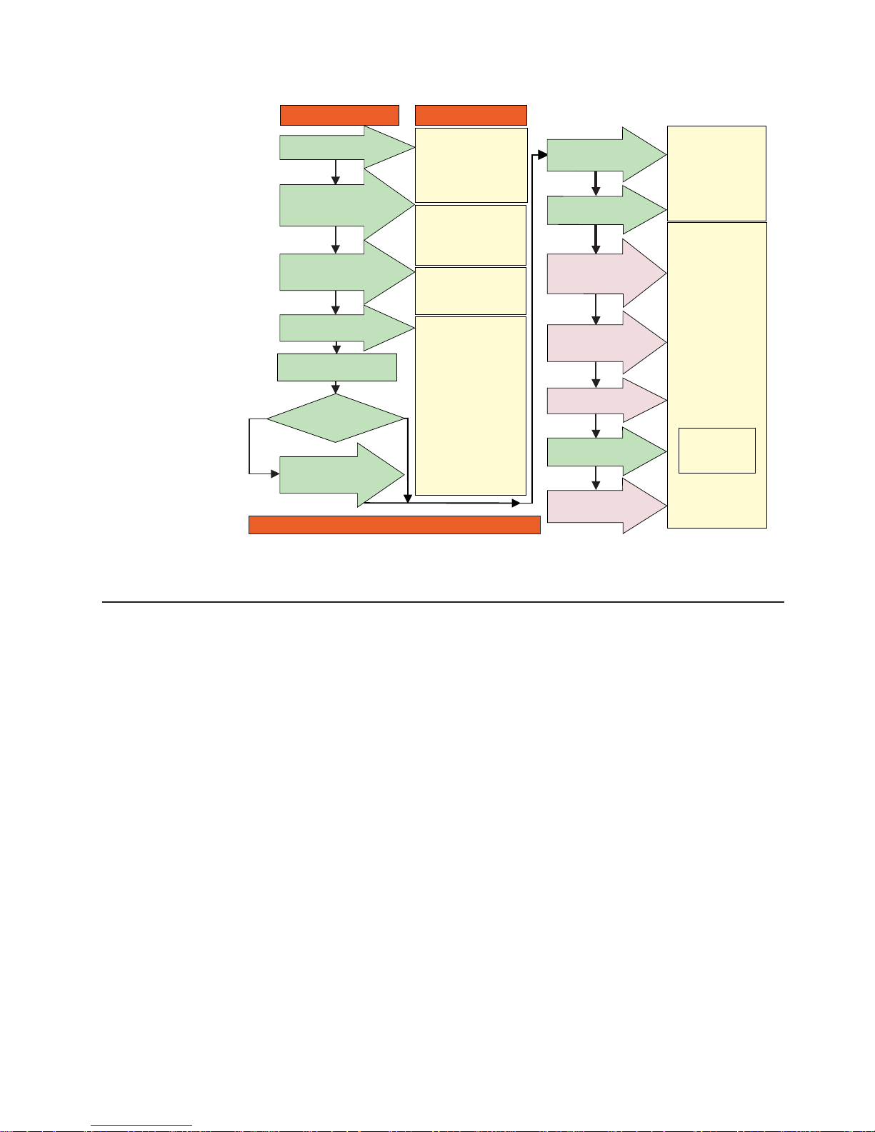
The following flow chart gives an overview of the DS4000 hardware and the
DS4000 Storage Manager software installation process. Lined arrows in the flow
chart indicate consecutive steps in the hardware and software installation process.
Labeled arrows indicate which current documents provide detailed information about
those steps.
xviii IBM TotalStorage DS4000 FC2-133 Dual Port Host Bus Adapter: Installation and User’s Guide
Page 21
Install Process Documentation
Plan installation
Connect Power and
Start Server
DS4000 Storage Server
Installation Guide
Complete SM SW
Installation
Configure Storage
Hardware
Online Help
Configure Storage
Subsystems on Host
Verify Server
operation w/ LEDs
Prepare for
Installation of
SM Software
Install and Verify
SM SW on Host and
Workstation
* FC Planning and
Integration: User's Guide
and Svc Info
DS4000 Storage Manager
Concepts Guide
DS4000 Storage Exp Encls
Install and User's Guides
DS4000 Fibre Channel
Storage Server
Installation Guides
Fibre Channel Cabling
Instructions
DS4000 and HBA Install
and User's Guides
DS4000 Storage Svr
Installation Guide
DS4000 RAID Controller
Enclosure Unit Install
and User's Guide
Copy Services
User's Guide
DS4000 Storage Manager
DS4000 Storage
Manager Installation
and Support
OS Guides
DS4000 Hardware
Maintenance Manual
DS4000 Problem
Determination Guide
Out-of-Band
In-Band
Make FC Connections
SET Link Speed
(1GB or 2GB)
Install Storage
Server/RAID Controller
Enclosure(s) in Rack
Install Network
Hardware; Prep are
Network Connection
Install Storage
Expansion Enclosure(s)
Determine
Management
Method
* For pSeries/POWER server and pSeries/POWER-supported HBA use only
sj001046
DS4000 Storage Server publications
The following tables present an overview of the DS4500, DS4400, DS4300 Fibre
Channel, and DS4100 SATA Storage Server product libraries, as well as other
related documents. Each table lists documents that are included in the libraries and
what common tasks they address.
You can access the documents listed in these tables at one of the following Web
sites:
www.ibm.com/servers/storage/support/disk/
www.ibm.com/shop/publications/order/
DS4500 storage server library
Table 2 on page xx associates each document in the DS4500 (previously
FAStT900) storage server library with its related common user tasks.
Figure 1. Installation process flow by current publications
About this document xix
Page 22

Table 2. TotalStorage DS4500 Fibre Channel Storage Server document titles by user tasks
Title User Tasks
Planning Hardware
Installation
Software
Installation
Configuration Operation and
Administration
Diagnosis and
Maintenance
IBM TotalStorage
DS4500 Installation
and Support Guide,
GC26-7727
U U U
IBM TotalStorage
DS4500 Fibre
Channel Cabling
Instructions,
GC26-7729
U U
IBM TotalStorage
DS4500 Storage
Server User’s
Guide, GC26-7726
U U U
IBM TotalStorage
DS4500 Rack
Mounting
Instructions,
GC26-7728
U U
xx IBM TotalStorage DS4000 FC2-133 Dual Port Host Bus Adapter: Installation and User’s Guide
Page 23

DS4400 storage server library
Table 3 associates each document in the DS4400 (previously FAStT700) storage
server library with its related common user tasks.
Table 3. TotalStorage DS4400 Fibre Channel Storage Server document titles by user tasks
Title User Tasks
Planning Hardware
Installation
Software
Installation
Configuration Operation and
Administration
Diagnosis and
Maintenance
IBM DS4400 Fibre
Channel Storage
Server User’s
Guide, GC26-7730
U U U U U
IBM DS4400 Fibre
Channel Storage
Server Installation
and Support Guide,
GC26-7731
U U U U
IBM DS4400 Fibre
Channel Cabling
Instructions,
GC26-7732
U U
About this document xxi
Page 24

DS4300 storage server library
Table 4 associates each document in the DS4300 (previously FAStT600) storage
server library with its related common user tasks.
Table 4. TotalStorage DS4300 Fibre Channel Storage Server document titles by user tasks
Title User Tasks
Planning Hardware
Installation
Software
Installation
Configuration Operation and
Administration
Diagnosis and
Maintenance
IBM TotalStorage
DS4300 Fibre
Channel Storage
Server Installation
and User’s Guide,
GC26-7722
U U U
IBM TotalStorage
DS4300 Rack
Mounting
Instructions,
GC26-7724
U U
IBM TotalStorage
DS4300 Fibre
Channel Cabling
Instructions,
GC26-7725
U U
IBM TotalStorage
DS4300 SCU Base
Upgrade Kit,
GC26-7740
U U
IBM TotalStorage
DS4300 SCU Turbo
Upgrade Kit,
GC26-7741
U U
IBM TotalStorage
DS4300 Turbo
Models 6LU/6LX
Upgrade Kit,
GC26-7723
U U
xxii IBM TotalStorage DS4000 FC2-133 Dual Port Host Bus Adapter: Installation and User’s Guide
Page 25

DS4100 storage server library
Table 5 associates each document in the DS4100 (previously FAStT100) storage
server library with its related common user tasks.
Table 5. TotalStorage DS4100 SATA Storage Server document titles by user tasks
Title User Tasks
Planning Hardware
Installation
Software
Installation
Configuration Operation and
Administration
Diagnosis and
Maintenance
IBM TotalStorage
DS4100 Installation,
User’s and
Maintenance Guide,
GC26-7733
U U U U U
IBM TotalStorage
DS4100 Cabling
Guide, 24P8973
U
About this document xxiii
Page 26

DS4000 Storage Manager Version 9 publications
Table 6 associates each document in the DS4000 Storage Manager (previously
FAStT Storage Manager) library with its related common user tasks.
Table 6. TotalStorage DS4000 Storage Manager Version 9 titles by user tasks
Title User tasks
Planning Hardware
installation
Software
installation
Configuration Operation and
administration
Diagnosis and
maintenance
IBM TotalStorage
DS4000 Storage
Manager Version 9
Installation and
Support Guide for
Windows
2000/Server 2003,
NetWare, ESX
Server, and Linux,
GC26-7706
U U U
IBM TotalStorage
DS4000 Storage
Manager Version 9
Installation and
Support Guide for
AIX, HP-UX, Solaris
and Linux on
POWER,
GC26-7705
U U U
IBM TotalStorage
DS4000 Storage
Manager Version 9
Copy Services
User’s Guide,
GC26-7707
U U U U
IBM TotalStorage
DS4000 Storage
Manager Version 9
Concepts Guide,
GC26-7734
U U U U U U
xxiv IBM TotalStorage DS4000 FC2-133 Dual Port Host Bus Adapter: Installation and User’s Guide
Page 27

Other DS4000 and DS4000-related documents
Table 7 associates each of the following documents with its related common user
tasks.
Table 7. TotalStorage DS4000 and DS4000–related document titles by user tasks
Title User Tasks
Planning Hardware
Installation
Software
Installation
Configuration Operation and
Administration
Diagnosis and
Maintenance
IBM Safety
Information,
P48P9741
U
IBM TotalStorage
DS4000 Quick Start
Guide, GC26-7738
U U
IBM TotalStorage
DS4000 Hardware
Maintenance
Manual,GC26-7702
U
IBM TotalStorage
DS4000 Problem
Determination
Guide, GC26-7703
U
IBM Fibre Channel
Planning and
Integration: User’s
Guide and Service
Information,
SC23-4329
U U U U
IBM TotalStorage
DS4000 FC2-133
Host Bus Adapter
Installation and
User’s Guide,
GC26-7736
U U
IBM TotalStorage
DS4000 FC2-133
Dual Port Host Bus
Adapter Installation
and User’s Guide,
GC26-7737
U U
IBM TotalStorage
DS4000 Fibre
Channel and Serial
ATA Intermix
Premium Feature
Installation Overview
GC26-7713
U U U U
Fibre Channel
Solutions - IBM
DS4000 EXP500
Installation and
User’s Guide,
59p5637
U U U U U
About this document xxv
Page 28

Table 7. TotalStorage DS4000 and DS4000–related document titles by user tasks (continued)
Title User Tasks
Planning Hardware
Installation
Software
Installation
Configuration Operation and
Administration
Diagnosis and
Maintenance
IBM TotalStorage
DS4000 EXP700
and EXP710
Storage Expansion
Enclosures
Installation, User’s,
and Maintenance
Guide, GC26-7735
U U U U U
IBM TotalStorage
DS4000 Hard Drive
and Storage
Expansion
Enclosures
Installation and
Migration Guide,
GC26-7704
U U
IBM DS4000
Management Suite
Java User’s Guide,
32P0081
U U
IBM Netfinity
®
Fibre
Channel Cabling
Instructions,
19K0906
U
IBM Fibre Channel
SAN Configuration
Setup Guide,
25P2509
U U U U
How this document is organized
Chapter 1, “Preparing and installing the DS4000 FC2-133,” on page 1 includes an
overview of the DS4000 FC2-133 features and contains the information and
instructions needed to prepare and install the DS4000 FC2-133.
Chapter 2, “Updating the DS4000 FC2-133 BIOS code and installing device
drivers,” on page 9 provides information for how to update the DS4000 FC2-133
BIOS code.
Chapter 3, “Configuring the DS4000 FC2-133 with Fast!UTIL,” on page 19 provides
detailed configuration information about how to customize the configuration of the
DS4000 FC2-133 and any fibre-channel devices that connect to the DS4000
FC2-133.
Chapter 4, “Adapter operating environment and specifications,” on page 25 contains
the DS4000 FC2-133 operating environment and specification information.
Chapter 5, “Troubleshooting,” on page 27 provides information about the types of
installation problems that can cause the DS4000 FC2-133 to function incorrectly.
xxvi IBM TotalStorage DS4000 FC2-133 Dual Port Host Bus Adapter: Installation and User’s Guide
Page 29

“Accessibility,” on page 29 provides information about alternate keyboard
navigation, which is a DS4000 Storage Manager accessibility feature. Accessibility
features help a user who has a physical disability, such as restricted mobility or
limited vision, to use software products successfully.
Notices used in this document
The caution and danger statements that this document uses also appear in the
multilingual Safety Information document that is provided with your DS4000 Storage
Server. Each caution and danger statement is numbered for easy reference to the
corresponding statements in the safety document.
This document can contain the following notices that are designed to highlight key
information.
v Note: These notices provide important tips, guidance, or advice.
v Important: These notices provide information that might help you avoid
inconvenient or problem situations.
v Attention: These notices indicate possible damage to programs, devices, or
data. An attention notice is placed just before the instruction or situation in which
damage could occur.
v Caution: These statements indicate situations that can be potentially hazardous
to you. A caution statement is placed just before the description of a potentially
hazardous procedure step or situation.
v Danger: These statements indicate situations that can be potentially lethal or
extremely hazardous to you. A danger statement is placed just before the
description of a potentially lethal or extremely hazardous procedure step or
situation.
Getting information, help, and service
If you need help, service, or technical assistance or just want more information
about IBM products, you will find a wide variety of sources available from IBM to
assist you. This section contains information about where to go for additional
information about IBM and IBM products, what to do if you experience a problem
with your IBM Eserver xSeries
™
or IntelliStation
®
system, and whom to call for
service, if it is necessary.
Before you call
Before you call, make sure that you have taken these steps to try to solve the
problem yourself:
v Check all cables to make sure that they are connected.
v Check the power switches to make sure that the system is turned on.
v Use the troubleshooting information in your system documentation, and use the
diagnostic tools that come with your system.
v Check for technical information, hints, tips, and new device drivers at the IBM
Support Web site:
www.ibm.com/servers/storage/support/disk/
v Use an IBM discussion forum on the IBM Web site to ask questions.
You
can solve many problems without outside assistance by following the
troubleshooting procedures that IBM provides in the online help or in the documents
that are provided with your system and software. The information that comes with
your system also describes the diagnostic tests that you can perform. Most xSeries
About this document xxvii
Page 30

and IntelliStation systems, operating systems, and programs come with information
that contains troubleshooting procedures and explanations of error messages and
error codes. If you suspect a software problem, see the information for the
operating system or program.
Using the documentation
Information about your xSeries or IntelliStation system and preinstalled software, if
any, is available in the documents that come with your system. This includes printed
documents, online documents, readme files, and help files. See the troubleshooting
information in your system documentation for instructions about how to use the
diagnostic programs. The troubleshooting information or the diagnostic programs
might tell you that you need additional or updated device drivers or other software.
Web sites
IBM maintains pages on the World Wide Web where you can get the latest
technical information and download device drivers and updates.
v For DS4000 information, go to the following Web site:
www.ibm.com/servers/storage/support/disk/
The support page has many sources of information and ways for you to solve
problems, including:
– Diagnosing problems, using the IBM Online Assistant
– Downloading the latest device drivers and updates for your products
– Viewing frequently asked questions (FAQ)
– Viewing hints and tips to help you solve problems
– Participating in IBM discussion forums
– Setting up e-mail notification of technical updates about your products
v
You can order publications through the IBM Publications Ordering System at the
following Web site:
www.elink.ibmlink.ibm.com/public/applications/publications/cgibin/pbi.cgi
v For the latest information about IBM xSeries products, services, and support, go
to the following Web site:
www.ibm.com/eserver/xseries
v For the latest information about IBM pSeries products, services, and support,, go
to the following Web site:
www.ibm.com/eserver/pseries/
v For the latest information about the IBM IntelliStation information, go to the
following Web site:
www-
132.ibm.com/content/home/store_IBMPublicUSA/en_US/IntelliStation_workstations.html
v For the latest information about operating system and HBA support, clustering
support, SAN fabric support, and Storage Manager feature support, see the
TotalStorage DS4000 Interoperability Matrix at the following Web site:
www.ibm.com/servers/storage/disk/ds4000/interop-matrix.html
Software service and support
Through IBM Support Line, for a fee you can get telephone assistance with usage,
configuration, and software problems with xSeries servers, IntelliStation
workstations, and appliances. For information about which products are supported
by Support Line in your country or region, go to the following Web site:
xxviii IBM TotalStorage DS4000 FC2-133 Dual Port Host Bus Adapter: Installation and User’s Guide
Page 31

www.ibm.com/services/sl/products
For more information about the IBM Support Line and other IBM services, go to the
following Web sites:
v www.ibm.com/services
v www.ibm.com/planetwide
Hardware service and support
You can receive hardware service through IBM Integrated Technology Services or
through your IBM reseller, if your reseller is authorized by IBM to provide warranty
service. Go to the following Web site for support telephone numbers:
www.ibm.com/planetwide
In the U.S. and Canada, hardware service and support is available 24 hours a day,
7 days a week. In the U.K., these services are available Monday through Friday,
from 9 a.m. to 6 p.m.
Fire suppression systems
A fire suppression system is the responsibility of the customer. The customer’s own
insurance underwriter, local fire marshal, or a local building inspector, or both,
should be consulted in selecting a fire suppression system that provides the correct
level of coverage and protection. IBM designs and manufactures equipment to
internal and external standards that require certain environments for reliable
operation. Because IBM does not test any equipment for compatibility with fire
suppression systems, IBM does not make compatibility claims of any kind nor does
IBM provide recommendations on fire suppression systems.
How to send your comments
Your feedback is important in helping us to provide the most accurate and
high-quality information. If you have comments or suggestions for improving this
publication, you can send us comments electronically by using these addresses:
v Internet: starpubs@us.ibm.com
v IBMLink from U.S.A.: STARPUBS at SJEVM5
v IBMLink from Canada: STARPUBS at TORIBM
v IBM Mail Exchange: USIB3WD at IBMMAIL
Be sure to include the name and order number of the document and, if
applicable, the specific location of the text you are commenting on, such as a
page number or table number.
You
can also mail your comments by using the Reader Comment Form in the back
of this manual or direct your mail to:
International Business Machines Corporation
Information Development
Department GZW
9000 South Rita Road
Tucson, Arizona
85744-0001
U.S.A.
About this document xxix
Page 32

When you send information to IBM, you grant IBM a nonexclusive right to use or
distribute the information in any way it believes appropriate without incurring any
obligation to you.
xxx IBM TotalStorage DS4000 FC2-133 Dual Port Host Bus Adapter: Installation and User’s Guide
Page 33

Chapter 1. Preparing and installing the DS4000 FC2-133
This chapter contains instructions on how to prepare and install the DS4000
FC2-133. It also describes the adapter components.
Overview
The DS4000 FC2-133 is a 2 Gbps high-performance, direct memory access (DMA),
bus master, fibre channel (FC) host bus adapter that is designed for high-end
systems. The function and performance are derived from the ISP2312 chip (see
Figure 2 on page 2), making the DS4000 FC2-133 a leading-edge host bus adapter.
The ISP2312 chip combines a powerful, reduced instruction set computer (RISC)
processor, a fibre-channel protocol manager (FPM) with two 2 Gbps fibre-channel
transceivers, and a peripheral component interconnect (PCI) or peripheral
component interconnect-extended (PCI-X) local bus interface in a single-chip
solution. The DS4000 FC2-133 supports all fibre-channel peripheral devices that
support private-loop direct attach (PLDA) and fabric-loop attach (FLA).
The DS4000 FC2-133 connects the following hardware:
v Mainframe computers
v Super computers
v Workstations
v Storage devices
v Servers
Overview of fibre channel
Fibre channel is a high-speed data transport technology used for mass storage and
networking. By using a fibre-channel arbitrated loop (FC-AL), 126 fibre-channel
devices can be supported, compared to 15 small computer system interface (SCSI)
devices with Ultra SCSI.
The DS4000 FC2-133 uses multimode shortwave optical interfaces for distances up
to 550 m (1804 ft.) when operating at 1 Gbps or up to 300 m (984 ft.) when
operating at 2 Gbps. The DS4000 FC2-133 supports data transfer rates up to 200
MBps half-duplex and 400 MBps full-duplex on optical interfaces.
For more information about fibre channel technology, see the SCSI-3 Fibre Channel
Protocol (SCSI-FCP) standard.
DS4000 FC2-133 features
The DS4000 FC2-133 has the following features:
v Compliance with the following standards and specifications:
– Intel
®
PCI Local Bus version 2.2 specification
– PCI-X addendum, revision 1.0 to the Intel PCI Local Bus version 2.2
specification
– Third Generation Fibre Channel Physical and Signaling Interface (PC-PH-3),
revision 9.2
– Fibre-channel arbitrated loop (FC-AL-2) standard
– U.S. and international safety and emissions standards
© Copyright IBM Corp. 2005 1
Page 34

v Supports direct memory access (DMA)
v Supports bus master
v Uses the Fast!UTILbasic input/output system (BIOS) utility program to customize
the configuration parameters on the DS4000 FC2-133 and attached drives
v Supports fibre channel protocol SCSI (FCP-SCSI) and fibre channel Internet
protocol (FCP-IP)
v Supports point-to-point fabric connection (F_PORT FABRIC LOGIN)
v Supports fibre channel service (Classes 2 and 3)
v Contains two independent channels on a single HBA
DS4000 FC2-133 components
Figure 2 identifies the DS4000 FC2-133 components that are referred to in this
document.
ISP2312
J3
J4
Bracket
Amber LED
Green LED
Optical interface connector
Each port has its own set of status light emitting diodes (LEDs). Table 8 on page 3
describes the green and amber LEDs and the activity that is indicated by the LEDs.
For more information about the DS4000 FC2-133 LED activity and troubleshooting,
see the installation, user’s and maintenance guide for your particular storage server
or IBM TotalStorage DS4000 Problem Determination Guide.
Figure 2. DS4000 FC2-133 components
2 IBM TotalStorage DS4000 FC2-133 Dual Port Host Bus Adapter: Installation and User’s Guide
Page 35

Table 8. DS4000 FC2-133 Adapter activity
Green LED Amber LED Activity Description
Off Off Power off The server adapter is not
receiving power. The server is
powered off.
On On Power The FC2-133 Adapter is receiving
power from the PCI or PCI-X slot
but is not initialized by the
adapter firmware.
On Off Online The FC2-133 Adapter is
successfully initialized by the
adapter firmware and is in a
ready state. The adapter firmware
is initialized when the adapter
BIOS code is loaded, Ctrl-Q is
pressed, or the operating system
driver is loaded.
Off On Signal acquired The FC2-133 Adapter firmware is
performing or waiting to perform
Fibre Channel loop initialization.
Off Flashing twice
per second
Loss of
synchronization
The FC2-133 Adapter has
detected a loss of synchronization
condition from the adapter Fibre
Channel receiver and is
attempting to resynchronize. A
loss of synchronization condition
might occur when a degraded
optical signal is received from the
LC-LC Fibre Channel cable or
optical interface connector.
Flashing twice
per second
Flashing twice
per second
Firmware error The FC2-133 Adapter firmware
has detected an unrecoverable
error condition.
Off Flashing once
per second
Beacon The adapter is responding to a
Beacon command from a HBA
management program.
The jumpers on the HBA set the default state of the laser and are set at the factory
with a jumper plug on pins 2-3 of the J3 and J4 jumpers.
Attention: Changing the jumper settings can result in the HBA being inoperable.
Preinstallation procedures
Complete the following tasks before you begin the installation:
v Read “Handling static-sensitive devices” on page 4.
v Read “What you need for the installation” on page 5.
v Write down the serial number of the DS4000 FC2-133. Each adapter has a
unique serial number. If the nonvolatile random access memory (NVRAM) (also
referred to as NOVRAM) is damaged, the system prompts you for the DS4000
FC2-133 serial number. Figure 3 on page 4 shows the location of the serial
number label.
Chapter 1. Preparing and installing the DS4000 FC2-133 3
Page 36

Serial number
label
Handling static-sensitive devices
Attention: Static electricity can damage electronic devices and your system. To
avoid damage, keep static-sensitive devices in their static-protective package until
you are ready to install them.
To reduce the possibility of electrostatic discharge (ESD), observe the following
precautions:
v Limit your movement. Movement can cause static electricity to build up around
you.
v Handle the device carefully, holding it by its edges or its frame.
v Do not touch solder joints, pins, or exposed printed circuitry.
v Do not leave the device where others can handle and possibly damage the
device.
v While the device is still in its static-protective package, you should hold the
device and touch an unpainted metal part of the system unit for at least 2
seconds. This drains static electricity from the package and from your body.
v Remove the device from its package and install it directly into your system unit
without setting it down. If it is necessary to set the device down, place it in its
static-protective package. Do not place the device on your system unit cover or
on a metal table.
v Take additional care when handling devices during cold weather because heating
reduces indoor humidity and increases static electricity.
Figure 3. DS4000 FC2-133 serial number label
4 IBM TotalStorage DS4000 FC2-133 Dual Port Host Bus Adapter: Installation and User’s Guide
Page 37

What you need for the installation
To install the DS4000 FC2-133 in your server, you will need a small Phillips
screwdriver. Depending on your configuration, you might need the following two
items:
v An LC-LC fibre channel cable1. This cable enables you to connect fibre-channel
nodes to a loop.
v LC-SC fibre channel cable1. This cable enables you to connect an LC-LC
fibre-channel cable to a device that requires an SC connector.
Installing the DS4000 FC2-133
Attention: To avoid damage to your fiber-optic cables, follow these guidelines:
v Do not route the cable along a folding cable-management arm.
v When you attach fiber-optic cables to a fibre-channel device on slide rails, leave
enough slack in the cables so that they do not bend to an angle smaller than 38
mm (1.5 in.) when they are extended or so that they do not become pinched
when retracted.
v Route the cable away from places where it can snag on other fibre-channel
devices in the rack.
v Do not overtighten the cable straps or bend the cables to an angle smaller than
38 mm (1.5 in.).
v Do not put excess weight on the cable at the connection point and be sure that
the cable is well-supported.
The
DS4000 FC2-133 comes with an attached standard 3U adapter bracket, as
shown in Figure 2 on page 2. A Low Profile 2U bracket also comes with the
adapter. Before you install the DS4000 FC2-133, check the size of the storage
server to verify whether you need the Low Profile 2U adapter bracket. If you need
to install the Low Profile 2U bracket, go to step 1. Otherwise, go to step 2.
1. Complete the following steps to install the Low Profile 2U adapter bracket:
a. Remove your DS4000 FC2-133 from the static-protective package. Set it
down on a nonconductive, static-protected surface (place it component side
up). Do not place the adapter on your system unit cover or on a metal
table.
b. Using a small Phillips screwdriver, carefully remove the two bracket screws
from the 3U adapter (you will reuse the two adapter screws). Remove the
3U adapter bracket and set it aside.
c. Align the two screw holes in the 2U adapter bracket with the two screws
holes on the adapter. Using the two screws that you removed in step 1b,
secure the bracket to the adapter.
d. Return the adapter to the static-protective package until you are ready for
installation.
2. Check the system board and make any configuration changes that are needed
to accommodate the DS4000 FC2-133.
Note: The DS4000 FC2-133 is self-configuring; however, some system boards
require manual configuration. For example, some systems have a PCI
Device Configuration menu in the system board setup BIOS code where
you must enable host bus adapters, bus-master slots, and interrupt
request (IRQ) levels. If the system board supports triggering, use level
1. These cables do not come with the DS4000 FC2-133 Dual Port Host Bus Adapter. Yo u must order them separately.
Chapter 1. Preparing and installing the DS4000 FC2-133 5
Page 38

triggering for the DS4000 FC2-133. For system specific configuration,
see the documentation that comes with your server, or contact your IBM
technical support representative to determine if your system board
requires configuration.
3. Turn off the peripheral devices. Then turn off the server.
4. Disconnect the power cords.
5. Remove the server cover.
6. Choose a PCI bus-master slot that supports bus mastering. Most system
boards automatically assign an IRQ level and interrupt line. If your system
board does not automatically assign an IRQ level and interrupt line, you must
assign an IRQ level and use interrupt line A for this PCI bus-master slot.
Before you install the adapter into a PCI bus-master slot, note the following
points:
v Some system boards have two kinds of PCI bus slots: master and
subordinate. The DS4000 FC2-133 must be in a PCI bus-master slot.
(Some system boards have PCI bus-master slots that are shared with
on-board devices. The DS4000 FC2-133 does not work in shared PCI
bus-master slots.)
v PCI connectors vary among system board manufacturers. The DS4000
FC2-133 is a 64-bit PCI device that can function in a 32-bit PCI bus-master
slot.
v The DS4000 FC2-133 is designed and tested to operate at PCI bus speeds
up to 66 MHz and PCI-X bus speeds up to 133 MHz.
v PCI and PCI-X slots look the same. If the server contains both PCI and
PCI-X bus-master slots, see the documentation that comes with the server
to determine the slot type.
7. Remove the expansion slot cover. Before you remove the cover, see the
documentation that comes with the server for specific removal instructions.
Attention: If you try to install the DS4000 FC2-133 into a PCI bus-master
slot that does not conform to the PCI specification, you might damage the
DS4000 FC2-133.
8. Align the adapter with the expansion slot. Carefully press it into the PCI
bus-master slot until it is fully seated and secure.
9. Connect one end of an LC-LC fibre-channel cable to one of the optical
interface connectors on the DS4000 FC2-133. Connect the other end of the
cable to a fibre-channel device. You can connect another device to the unused
optical interface connector.
10. Carefully install and secure the server cover.
11. Connect the power cables.
12. Turn on all external fibre-channel devices. Then turn on the server. The
following information is displayed when the server processor architecture is
Intel Architecture 32 bit (IA-32), Intel Extended Memory 64 Technology
(EM64T) or the Advance Micro Devices 64 bit (AMD-64):
QLogic Corporation QLA2312 PCI Fibre Channel ROM BIOS Version X.XX
Copyright (C) QLogic Corporation 1993-2002 All Rights Reserved. www.qlogic.com
Press <Ctrl+Q> for Fast!UTIL BIOS for Adapter 0 is disabled ROM BIOS not installed
Note: This BIOS banner does not display when the adapter is in a server with an
Intel 64 bit processor (IA-64) or a Sun SPRAC processor architecture.
6 IBM TotalStorage DS4000 FC2-133 Dual Port Host Bus Adapter: Installation and User’s Guide
Page 39

To display the fibre-channel devices, press Ctrl+Q, and then use the Fast!UTIL
program. See Chapter 3, “Configuring the DS4000 FC2-133 with Fast!UTIL,” on
page 19 for detailed information about Fast!UTIL.
If the information that is displayed is correct, go to Chapter 2, “Updating the
DS4000 FC2-133 BIOS code and installing device drivers,” on page 9 for detailed
instructions on how to update the DS4000 FC2-133 BIOS code.
If the information that is displayed is not correct and you have checked the adapter
configuration, go to Chapter 5, “Troubleshooting,” on page 27 for problem solving
information.
Chapter 1. Preparing and installing the DS4000 FC2-133 7
Page 40

8 IBM TotalStorage DS4000 FC2-133 Dual Port Host Bus Adapter: Installation and User’s Guide
Page 41

Chapter 2. Updating the DS4000 FC2-133 BIOS code and
installing device drivers
Important: The information in this section is applicable when the server processor
architecture is Intel Architecture 32 bit (IA-32), Intel Extended Memory 64
Technology (EM64T) or the Advance Micro Devices 64 bit (AMD-64). It does not
apply when the server processor architecture is Intel Architecture 64 bit. When the
adapter is installed in a server with an Intel 64 bit processor (IA-64), see the
readme in the FC2-133 HBA EFI driver package for instructions about how to load
the EFI driver (instead of BIOS code) and update the adapter NVRAM settings.
After you install the DS4000 FC2-133, you must update the BIOS code, update the
nonvolatile random access memory (NVRAM), and install the device drivers.
Important: The BIOS Update Utility treats each of the two fibre-channel ports of the
DS4000 FC2-133 as a separate port. This means that if you program the flash or
NVRAM using the I/O address of one DS4000 FC2-133 port, you must repeat the
same process to program the other DS4000 FC2-133 port.
You can update the adapter BIOS code either by using the BIOS Update Utility from
the support CD that comes with the adapter (see “Updating the BIOS code and
NVRAM from the support CD”) or by creating and using a BIOS Update Utility
diskette (see “Updating the BIOS code and NVRAM from the BIOS Update Utility
diskette” on page 12).
To install the device drivers, see “Installing the DS4000 FC2-133 device drivers” on
page 15.
Note: For the latest information about supported operating systems, versions of
device drivers, utilities, and documentation, go to the following Web site:
www.ibm.com/pc/support/
Updating the BIOS code and NVRAM from the support CD
To update the DS4000 FC2-133 BIOS code and NVRAM using the BIOS Update
Utility on the support CD, choose one of the following methods:
v flasutil command prompt. Use this method to type in command-line options. See
“Using the flasutil command prompt.”
v flasutil BIOS Update Utility menu. Use this method to select a command-line
option from the menu. See “Using the flasutil BIOS Update Utility menu” on page
11.
Using the flasutil command prompt
Complete the following steps to update the DS4000 FC2-133 BIOS code and
NVRAM using the command line:
1. Insert the IBM TotalStorage DS4000 FC2-133 Dual Port Host Bus Adapter
Support CD into the CD-ROM drive. Restart the server. Your server displays a
DOS prompt.
2. Update the BIOS code in the flash utility by typing the following command:
flasutil /f
Press Enter.
3. Update the NVRAM by typing the following command:
© Copyright IBM Corp. 2005 9
Page 42

flasutil /l
Press Enter.
4. Update the standard BIOS defaults in the flash utility to the new defaults from
the NVRAM files by typing the following command:
flasutil /u
Press Enter.
5. To review additional command-line options that you can use, go to “Additional
command-line options.” Then return to step 6.
6. Remove the support CD from the CD-ROM drive and restart the server.
7. Go to “Installing the DS4000 FC2-133 device drivers” on page 15.
Additional command-line options
This section describes additional command-line options that you can use. Complete
the following steps to review these command-line options:
1. At the DOS prompt, type the following command: flasutil /?
2. Press Enter.
The following command-line options display:
/F xxxx = Write Flash, adapter address = xxxx
If no address specified then write Flash to all adapters
/W xxxx = Copy Flash to file: QLxxRIM.SAV, adapter type = xxxx
/O <filename.ext> = Use <filename.ext> instead of QLxxROM.BIN
/I = Ignore Subsystem ID /P = Program all adapters
/M = Don’t prompt for I/O address
/Q = Quiet Mode, no messages will be displayed
/S xxxx = Display serial number of adapter at address xxxx
If no address specified then display the serial number of all adapters
/V xxxx = Display current version number of BIOS on adapters at address xxxx
If no address specified then display the BIOS version of all adapters
/C xxxx = Verify Flash of adapter at address xxxx
If no address specified verify the Flash of all adapters
/Y xxxx = Display port name of adapter at address xxxx
If no address specified then display port name of all adapters
/L xxxx = Write NOVRAM, adapter address = xxxx
If no address specified then write NOVRAM to all adapters
/D xxxx = Copy NOVRAM to file: QL1xNVRM.SAV, adapter address = xxxx
/U xxxx = Update BIOS NOVRAM defaults, adapter address = xxxx
If no address specified then write then update all adapters
/N <filename.ext> = Use <filename.ext> instead of NVRMxx0.DAT
/T = Multiport Fibre Channel adapter
/X xxxx = Verify NOVRAM of adapter at address xxxx
Notes:
1. All of the listed options are supported and you can run them from the command
line. Options /L, /D, /U, /N, /T, and /X might not display.
2. The command-line option is not case-sensitive. Either /f or /F can be used to
initiate the adapter flash BIOS update.
Table 9 on page 11 shows additional command-line options that you can use, along
with an explanation of each option.
10 IBM TotalStorage DS4000 FC2-133 Dual Port Host Bus Adapter: Installation and User’s Guide
Page 43

Table 9. Examples of flasutil command-line options
Command Description
flasutil /L Write NVRAM on all DS4000 host bus adapters in a system
without being prompted for an I/O address.
flasutil /W F600 Save the existing flash code to file QL2312RM.SAV.
flasutil /L f400 Write NVRAM to the adapter at I/O address f400.
flasutil /L f800 /F f800 Write NVRAM and flash an adapter at I/O address f800.
flasutil /L /F Write NVRAM and flash all adapters.
flasutil /D Save NVRAM to file QL23NVRM.SAV.
flasutil /U Update BIOS NVRAM defaults.
flasutil /X Verify NVRAM in all adapters.
Using the flasutil BIOS Update Utility menu
Complete the following steps to update the DS4000 FC2-133 BIOS code and
NVRAM by using the flasutil BIOS Update Utility menu:
1. Insert the IBM TotalStorage DS4000 FC2-133 Dual Port Host Bus Adapter
Support CD into the CD-ROM drive. Restart the server. Your server displays a
DOS prompt.
2. Type the following command: flasutil
Press Enter.
3. A list of adapters and I/O addresses displays. At the command prompt, type the
appropriate I/O address and press Enter.
4. The following option menu displays:
F = Write Flash
W = Copy Flash to file: QLxxROM.SAV
S = Display serial number
V = Display current BIOS version
C = Verify Flash
Y = Display port name
L = Write NOVRAM
A = Write NOVRAM and defaults
D = Copy NOVRAM to file:QLxxNVRM.SAV
U = Update BIOS NOVRAM defaults
X = Verify NOVRAM
Notes:
a. All of the listed options are supported and you can run them from the
command line. Options L, A, D, U, and X might not display. The
command-line option is not case-sensitive.
b. You can configure each adapter with more than one option.
5.
Type the letter for the option that you want and press Enter.
6. If you have additional adapters installed, if you want to program the other port of
the adapter, or if you want to configure your adapter with more than one option,
continue with step 7. Otherwise, go to step 8.
7. Repeat steps 2 through 5 for each additional adapter or port.
8. Remove the CD from the CD-ROM drive and restart the server.
9. Go to “Installing the DS4000 FC2-133 device drivers” on page 15.
Chapter 2. Updating the DS4000 FC2-133 BIOS code and installing device drivers 11
Page 44

Updating the BIOS code and NVRAM from the BIOS Update Utility
diskette
If you cannot use the support CD to update the adapter BIOS code, you can create
a diskette using the support CD. The following sections describe how to create and
use the diskette.
Note: For a Novell NetWare environment, you will need to unpack the BIOS
Update Utility diskette using a server that is running a Microsoft
®
Windows
NT®, Windows
®
2000, or Linux operating system.
Creating the BIOS Update Utility diskette
Create the BIOS Update Utility diskette by copying the image you need from the
IBM TotalStorage DS4000 FC2-133 Dual Port Host Bus Adapter Support CD or by
downloading the image from the following Web site:
www.ibm.com/pc/support
For Microsoft Windows NT or Windows 2000
Complete the following steps to create a BIOS Update Utility diskette for Microsoft
Windows NT or Windows 2000 from the IBM TotalStorage DS4000 FC2-133 Host
Bus Adapter Support CD:
1. Insert the support CD into the CD-ROM drive.
2. Insert a diskette into the diskette drive.
3. At the command prompt, type the following command:
d:\tools\dsk4w32 d:\images\biosnvrm\23x0\2342_xxx.img a:
Where d is the CD-ROM drive and a is the diskette drive.
4. Press Enter.
5. Remove the support CD from the CD-ROM drive.
6. Remove the diskette from the diskette drive and label the diskette appropriately.
For Linux
Complete the following steps to create a BIOS Update Utility diskette for Linux from
the IBM TotalStorage DS4000 FC2-133 Dual Port Host Bus Adapter Support CD:
1. Insert the support CD into the CD-ROM drive and restart the server.
2. Insert a diskette into the diskette drive.
3. At the command prompt, type the following command: mount -t
iso9660/dev/cdromdevicefile /mnt
Where cdromdevicefile is the specific device file for the CD-ROM block device.
4. Press Enter.
5. Type: dd if=/mnt/images/biosnvrm/23x0/2342_xxx.img
of=/dev/diskettedevicefile bs=32
Press Enter.
6. Unmount the CD-ROM by typing the following command: unmount /mnt
7. Remove the support CD from the CD-ROM drive.
8. Remove the diskette from the diskette drive and label the diskette appropriately.
Updating the BIOS code and NVRAM from the diskette
Use one of the following methods to update the BIOS code and NVRAM using the
BIOS Update Utility from the diskette:
12 IBM TotalStorage DS4000 FC2-133 Dual Port Host Bus Adapter: Installation and User’s Guide
Page 45

v flasutil command prompt. Use this method to type in command-line options. See
“Using the flasutil command prompt.”
v flasutil BIOS Update Utility menu. Use this method to select a command-line
option from the menu. See “Using the flasutil BIOS Update Utility menu” on page
14.
Important:
The BIOS Update Utility treats each of the two fibre-channel ports of the
DS4000 FC2-133 adapter as a separate port. This means that if you program the
flash or NVRAM using the I/O address of one DS4000 FC2-133 port, you must
repeat the same process to program the other DS4000 FC2-133 port.
Using the flasutil command prompt
Complete the following steps to update the BIOS code and NVRAM using the
flasutil command prompt:
1. Insert the BIOS Update Utility diskette that you created into the diskette drive
and restart the server. Your server displays a DOS prompt.
2. Update the BIOS in the flash utility by typing the following command: flasutil
/f
Press Enter.
3. Update the NVRAM by typing the following command: flasutil /l
Press Enter.
4. Update the standard BIOS defaults in the flash utility to the new defaults from
the NVRAM files by typing the following command: flasutil /u
Press Enter.
5. To review additional command-line options that you can use, continue with
“Command-line options.” Otherwise, continue with step 6.
6. Remove the diskette from the diskette drive and restart the server.
7. Go to “Installing the DS4000 FC2-133 device drivers” on page 15.
Command-line
options: This section describes additional command-line options
that you can use. Complete the following steps to review these command-line
options:
1. At the DOS prompt, type the following command: flasutil /?
2. Press Enter.
Chapter 2. Updating the DS4000 FC2-133 BIOS code and installing device drivers 13
Page 46

The following command-line options display:
/F xxxx = Write Flash, adapter address = xxxx
If no address specified then write Flash to all adapters
/W xxxx = Copy Flash to file: QLxxRIM.SAV, adapter type = xxxx
/O <filename.ext> = Use <filename.ext> instead of QLxxROM.BIN
/I = Ignore Subsystem ID /P = Program all adapters
/M = Don’t prompt for I/O address
/Q = Quiet Mode, no messages will be displayed
/S xxxx = Display serial number of adapter at address xxxx
If no address specified then display the serial number of all adapters
/V xxxx = Display current version number of BIOS on adapters at address xxxx
If no address specified then display the BIOS version of all adapters
/C xxxx = Verify Flash of adapter at address xxxx
If no address specified verify the Flash of all adapters
/Y xxxx = Display port name of adapter at address xxxx
If no address specified, then display port name of all adapters
/L xxxx = Write NOVRAM, adapter address = xxxx
If no address specified then write NOVRAM to all adapters
/D xxxx = Copy NOVRAM to file: QL1xNVRM.SAV, adapter address = xxxx
/U xxxx = Update BIOS NOVRAM defaults, adapter address = xxxx
If no address specified then write then update all adapters
/N <filename.ext> = Use <filename.ext> instead of NVRMxx0.DAT
/T = Multiport Fibre Channel adapter
/X xxxx = Verify NOVRAM of adapter at address xxxx
Notes:
a. All of the listed options are supported and you can run them from the
command line. Options /L, /D, /U, /N, /T, and /X might not display.
b. The command-line option is not case-sensitive. Either /f or /F can be used to
initiate the adapter flash BIOS update.
Table
9 on page 11 describes examples of additional command-line options that
you can use.
Using the flasutil BIOS Update Utility menu
Complete the following steps to update your BIOS code and NVRAM using the
flasutil BIOS Update Utility:
1. Insert the BIOS Update Utility diskette into the diskette drive and restart the
server. Your server displays a DOS prompt.
2. From the DOS prompt, type: flasutil
3. Press Enter.
4. A list of adapters and I/O addresses displays. At the command prompt, type
the appropriate I/O address and press Enter.
5. The following option menu displays:
F = Write Flash
W = Copy Flash to file: QLxxROM.SAV
S = Display serial number
V = Display current BIOS version
C = Verify Flash Y = Display port name
L = Write NOVRAM A = Write NOVRAM and defaults
D = Copy NOVRAM to file: QLxxNVRM.SAV
U = Update BIOS NOVRAM defaults
X = Verify NOVRAM
14 IBM TotalStorage DS4000 FC2-133 Dual Port Host Bus Adapter: Installation and User’s Guide
Page 47

Notes:
a. All of the listed options are supported and you can run them from the
command line. Options L, A, D, U, and X might not display. The
command-line option is not case-sensitive.
b. You can configure each adapter with more than one option.
6. Type the letter for the option that you want and press Enter.
7. If you have additional adapters installed, if you want to program the other port
of the adapter, or if you want to configure your adapter with more than one
option, continue with step 8. Otherwise, go to step 9.
8. Repeat steps 2 through 5 for each additional adapter or port.
9. Remove the CD from the CD-ROM drive and restart the server.
10. Go to “Installing the DS4000 FC2-133 device drivers.”
Installing the DS4000 FC2-133 device drivers
The device drivers and installation instructions for the following supported operating
systems are provided on the IBM TotalStorage DS4000 FC2-133 Dual Port Host
Bus Adapter Support CD:
v Microsoft Windows 2000 and 2003
v Novell NetWare
v Linux
The
device driver installation instructions are in a readme file located in the
appropriate operating system directory.
Note: For the latest supported operating systems, versions of the device drivers,
utilities, and documentation, go to the following Web site:
www.ibm.com/pc/support
Using IBM FastT-MSJ utility
This section provides an overview of the IBM FastT-MSJ (Management Suite Java)
utility that can be used by advanced users to customize the configuration of the IBM
FC2-133 HBA when it is installed in a server. For more detailed information, see the
IBM DS4000 Management Suite Java User’s Guide version 1.0 or later that is
available at the following Web site: www.ibm.com/servers/storage/support/disk/
Overview of the IBM FAStT MSJ utility
The FAStT-MSJ utility is used to configure a storage area network (SAN)
environment made up of DS4000 Fibre Channel HBAs. It is a network-capable
application that can connect to and configure remote systems, enabling centralized
management and configuration of an entire SAN containing HBA components,
storage devices, and host systems.
You can use FAStT-MSJ to manage and control one or more DS4000 Fibre
Channel HBAs that are installed on local or remote systems. The FAStT-MSJ utility
is used, along with problem determination procedures (PDPs), on new or existing
installations to help diagnose Fibre Channel (FC) subsystem problems in adapters,
controllers, and devices that are attached to the FC fabric or loop.
You can also perform the following operations using the FAStT-MSJ utility to
configure devices in your system:
Chapter 2. Updating the DS4000 FC2-133 BIOS code and installing device drivers 15
Page 48

Disable (unconfigure) a device on a host bus adapter
When a device is set as unconfigured, it is not recognized by the HBA and
is not accessible to the HBA on that system.
Enable a device
This operation adds a device and makes it accessible to the HBA on that
system.
Designate a path as an alternate or preferred path (for Linux operating system
enviroments only)
When a device is accessible from more than one adapter in the same
system, you can assign one path as the preferred path and the other path
as an alternate path. If the preferred path fails, the system switches to the
alternate path to make sure that the transfer of data is not interrupted.
Note:
The diagnostic functions of the FAStT-MSJ utility are available for all
supported operating systems. The configuration functions of the FAStT-MSJ
utility are available only for Linux operating systems.
Installation and System Requirements
Make sure that you are using the latest version of the DS4000 FastT-MSJ for the
IBM DS4000 Host Bus Adapters. For the latest information about the FastT-MSJ
utility, go to the IBM DS4000 Support Web site:
www.ibm.com/servers/storage/support/disk/
The latest instructions and system requirements are in the documentation that come
with the utility.
Features
The FAStT-MSJ utility lets you:
v Set the FAStT-MSJ utility options
v Connect to hosts
v Disconnect from a host
v View detailed event and alarm-log information
v Use host-to-host SAN configuration policies
v Configure port devices
v Use logical unit number (LUN) level configuration
v Monitor in real-time to see when failovers occur, using the Failover Watcher
v Control host-side agent operations, including setting of the host agent polling
interval
v Review host adapter information, including:
– General information
– Statistics
– Information about attached devices
– Link status for attached device
v
Perform adapter functions, including:
– Configuring the adapter NVRAM settings
– Executing fibre diagnostics (read/write buffer loopback tests)
– Perform flash updates on an adapter
– Perform NVRAM updates on an adapter
16 IBM TotalStorage DS4000 FC2-133 Dual Port Host Bus Adapter: Installation and User’s Guide
Page 49

v Manage configurations:
– Save configurations for off-line policy checks and SAN integrity
– Load configurations from a file if the host is off-line for policy checks and SAN
integrity
v Confirm security
Utilities
Using the Utilities section of the FastT-MSJ utility you can update I/O expansion
card firmware and perform adapter-level configurations on a host-connected
adapter.
Note: You may be prompted for a password. The default password is config.
Update flash
When you click Update Flash in the Utilities section of the FastT-MSJ utility, and
the adapter accepts the update, the application prompts for the file name of the new
flash BIOS firmware. The latest version of DS4000 FC2-133 HBA flash BIOS
firmware is available from the IBM Support Web site at:
www.ibm.com/servers/storage/support/disk/
The flash BIOS firmware file name ends with .bin (for example, QL2312RM.bin).
After you enter a valid flash BIOS firmware file name, click OK to complete with the
update, or click Cancel to abort. When you click OK, the FAStT-MSJ utility verifies
the file name and format of the new file. If the file is valid, the application then
compares the version of the file with the adapter flash version that is currently
installed. If the installed adapter version is the same or newer than the file flash
version you are trying to install, the application asks if you still want to update the
flash.
If the firmware update fails, an error message displays.
Update NVRAM
When you click Update NVRAM in the Utilities section of the FastT-MSJ utility, and
the adapter accepts the update, the application prompts for the file name of the new
NVRAM firmware. The latest version of the DS4000 FC2-133 HBA NVRAM
firmware is available from the following Web site:
www.ibm.com/servers/storage/support/disk/
The NVRAM firmware file name ends with .dat (for example, nvram23.dat).
After you enter a valid NVRAM firmware file name, click OK to complete with the
update, or click Cancel to abort. When you click OK, the FAStT-MSJ utility verifies
the content of the new file and then updates the firmware.
If the firmware update fails, an error message displays.
Note: Updating NVRAM firmware resets the configuration to default settings. After
updating NVRAM firmware, all custom configuration settings will need to be
entered again.
Chapter 2. Updating the DS4000 FC2-133 BIOS code and installing device drivers 17
Page 50

18 IBM TotalStorage DS4000 FC2-133 Dual Port Host Bus Adapter: Installation and User’s Guide
Page 51

Chapter 3. Configuring the DS4000 FC2-133 with Fast!UTIL
This chapter provides detailed configuration information for advanced users who
want to customize the configuration of the DS4000 FC2-133 and the connected
fibre-channel devices. You can configure the adapter using the Fast!UTIL utility.
Starting Fast!UTIL
When the adapter is installed in the server with an Intel 32 bit processor(IA-32), an
Intel Extended Memory 64 bit Technology (EM64T) processor, or an Advance Micro
Devices 64 bit (AMD-64) architecture only, you can access Fast!UTIL by pressing
Ctrl+Q during the BIOS initialization; it might take a few seconds for the Fast!UTIL
menu to display. Fast!UTIL prompts you to select the adapter that you want to
configure. After you change the settings that are described in the “Host bus adapter
settings” on page 20 section,Fast!UTIL restarts the system to enable the new
parameters. When the adapter is installed in a server with an Intel 64 bit processor
(IA-64), see the readme in the FC2-133 HBA EFI driver package for instructions
about how to modify the NOVRAM adapter settings.
Important: If the configuration settings are incorrect, the DS4000 FC2-133 will not
function properly. Do not modify the default configuration settings unless you are
instructed to do so by an IBM technical support representative or by the installation
instructions. The default settings are for a typical Microsoft Windows installation.
See the DS4000 FC2-133 device driver readme file of the appropriate operating
system for the required NVRAM setting modifications for that operating system.
Note: An alternative method to update the BIOS and the adapter NOVRAM
settings is to use the IBM FAStT Management Suite Java (FAStT-MSJ).
FAStT-MSJ can be downloaded from the following Web site:
www.ibm.com/servers/storage/support/disk/
Accessing HBA settings through Fast!UTIL
The Fast!UTIL feature provides access to host bus adapter settings. To access this
feature, simultaneously press and hold the ALT + Q keys or the Ctrl + Q keys
during BIOS initialization. It may take a few seconds for the Fast!UTIL menu to
appear. If more than one board is installed, Fast!UTIL prompts you to select a board
to configure. After you change adapter settings, Fast!UTIL reboots your system to
load the new parameters. Upon entering Fast!UTIL, the following selections are
available on the Fast!UTIL Options menu:
v Configuration Settings
v Scan Fibre Devices
v Fibre Disk Utility
v Loopback Test
v Select Host Adapter
v Exit FASt!UTIL
You
can access the host bus adapter settings through the Configuration Settings
menu in Fast!UTIL. See “Host bus adapter settings” on page 20 and“Advanced
Adapter Settings” on page 21 for detailed information on the settings.
© Copyright IBM Corp. 2005 19
Page 52

Host bus adapter settings
You can modify most of the host bus adapter settings. The current default settings
for the host bus adapter are listed in “Advanced Adapter Settings” on page 21.
These settings are described following the table. Yo u can modify the following
default host bus adapter settings.
BIOS address
The BIOS address is the I/O address where the BIOS code is stored when
you press Ctrl+Q or when you have the BIOS code enabled for starting
from the root directory. This is the address of the BIOS code in ROM
shadow memory. Multiple adapters can be installed in the server, but only
one BIOS instance is loaded for all of the adapters.
Note: The BIOS code is loaded from the first port of the first adapter that
the server recognizes. This code is used for all remaining DS4000
FC2-133 Single Port and DS4000 FC2-133 Dual Port adapters in the
same bus or server. The level of BIOS code that is loaded does not
affect other adapters with earlier BIOS code levels.
Revision
The BIOS revision is the revision number of the BIOS code that is loaded
from the first DS4000 FC2-133 that the server recognizes. Each DS4000
FC2-133 in the server has the same BIOS code revision number because
only one BIOS code instance is loaded.
Adapter serial number
The adapter serial number is located on the noncomponent side of the
adapter. See Figure 3 on page 4 for the location of the serial number label.
Interrupt level
The interrupt level is the interrupt that is used by the DS4000 FC2-133. The
interrupt level can change when the operating system is installed.
Adapter port name
This is the worldwide port name.
Host adapter BIOS
When this setting is Disabled, the ROM BIOS on the FC2-133 HBA is
Disabled, freeing space in upper memory. This setting must be Enabled if
you are booting from an fibre channel disk drive attached to the FC2-133
board. The default is Disabled.
Frame size
This setting specifies the maximum frame length supported by the FC2-133
HBA. The default size is 2048, which provides maximum performance for
F-Port (point-to-point) connections.
Loop reset delay
After resetting the loop, the firmware refrains from initiating any loop activity
for the number of seconds specified in this setting. The default is 5 seconds
Adapter hard loop ID
This setting forces the adapter to attempt to use the ID specified in the
Hard Loop ID setting. The default is Enabled.
Hard loop ID
If the Adapter Hard Loop ID setting is Enabled, the adapter attempts to use
the ID specified in this setting. The default ID is 125. You should set this ID
to a unique value from 0-125 if there is more than one adapter connected
to a FC-AL loop and the Adapter Hard Loop ID setting is Enabled.
20 IBM TotalStorage DS4000 FC2-133 Dual Port Host Bus Adapter: Installation and User’s Guide
Page 53

Spin up delay
When this bit is set, the BIOS will wait up to 5 minutes to find the first drive.
The default setting is Disabled.
Connection Options
This setting defines the type of connection (loop or point to point) or
connection preference. The default is 2.
Fibre Channel Tape Support
This setting enables FCP-2 recovery. The default is Enabled. You should
change this setting to Disabled if the HBA is connected to a DS4000
storage server. The DS4000 storage server does not support a tape device
through the same Fibre-Channel HBA from the host server.
Data Rate
This setting determines the data rate. When this setting is 0, the FC2-133
HBA runs at 1 gbps. When this setting is 1, the FC2-133 HBA runs at 2
gbps. When this setting is 2, Fast!UTIL determines what rate your system
can accommodate and sets the rate accordingly. The default is 2
(auto-configure).
Advanced Adapter Settings
Access the following advanced host bus adapter settings through the Configuration
Settings menu in Fast!UTIL and select Advanced Adapter Settings. The default
settings for the FC2-133 HBA are as follows:
Execution Throttle
This setting specifies the maximum number of commands executing on any
one port. When the execution throttle of a port is reached, no new
commands are executed until the current command finishes executing. The
valid options for this setting are 1-256. The default is 255.
LUNs per Target
This setting specifies the number of LUNs per target. Multiple LUN support
is typically for redundant array of independent disks (RAID) boxes that use
LUNs to map drives. The default is 0. For host operating systems other
than Microsoft Windows, one may need to change this setting to a value
other 0 to allow the host to see more than one logical drive from the
DS4000 Storage Server. Review the device driver README for the
appropriate setting for environments other than Microsoft Windows
Operating System.
Enable LIP Reset
This setting determines the type of loop initialization process (LIP) reset that
is used when the operating system initiates a bus reset routine. When this
setting is Yes, the driver initiates a global LIP reset to clear the target
device reservations. When this setting is No, the driver initiates a global LIP
reset with full login. The default is No.
Enable LIP Full Login
This setting instructs the ISP chip to re-login to all ports after any LIP. The
default is Yes.
Enable Target Reset
This setting enables the drivers to issue a Target Reset command to all
devices on the loop when a SCSI Bus Reset command is issued. The
default is Yes.
Login Retry Count
This setting specifies the number of times the software tries to log in to a
Chapter 3. Configuring the DS4000 FC2-133 with Fast!UTIL 21
Page 54

device. The default is 30 retries for Microsoft Windows Operating System
environment. Please review the device driver README for the correct
setting in other operating system environments.
Port Down Retry Count
This setting specifies the number of seconds that the software waits before
it retries a command to a port returning port down status. The default is 30
seconds. In a DS4000 storage server configuration with the maximum
number of drive expansion enclosures, you should increase this setting to
70.
Link Down Timeout
This setting specifies the number of seconds the software that the software
waits for a link down to come up. The default is 60 seconds.
Extended Error Logging
This setting provides additional error and debug information to the operating
system. When enabled, events are logged into the Windows NT Event
Viewer. The default is Disabled.
Operation Mode
This setting specifies the reduced interrupt operation (RIO) modes, if
supported by the software driver. RIO modes allow posting multiple
command completions in a single interrupt. The default is 0.
Interrupt Delay Timer
This setting contains the value (in 100-microsecond increments) that is
used by a timer to set the wait time between accessing (DMA) a set of
handles and generating an interrupt. The default is 0.
Selectable boot settings
When you set the Selectable Boot Settings option to Enabled, you can select the
worldwide port name of the fibre-channel hard disk from which you want to start up
(boot). When this option is set to Enabled, the node starts from the selected
fibre-channel hard disk, ignoring any IDE or SCSI hard disks that are attached to
your server. When this option is set to Disabled, the Boot ID and Boot LUN
parameters have no effect.
The BIOS code in some new systems supports selectable start up, which
supersedes the Fast!UTIL selectable start up setting. To start from a fibre-channel
hard disk that is attached to the DS4000 FC2-133, select the attached fibre-channel
hard disk from the system BIOS menu.
Note: The Selectable Boot Settings option for the DS4000 FC2-133 applies to only
fibre-channel hard disk drives.
Restore default settings
You can use the Restore Default Settings option to restore the DS4000 FC2-133
default settings and NVRAM.
The default NVRAM settings are the adapter settings that were saved the last time
an NOVRAM update operation was run from the BIOS Update Utility program
(option U or command line /U switch). If the BIOS Update Utility program has not
been used to update the default NOVRAM settings since the adapter was installed,
the factory settings are loaded.
22 IBM TotalStorage DS4000 FC2-133 Dual Port Host Bus Adapter: Installation and User’s Guide
Page 55

Note: After selecting Restore default settings, check the NVRAM settings (for
example the host bus adapter and advanced adapter settings) against the
values that are recommended in this document and in the device driver
READMEs for the appropriate operating system.
Raw NOVRAM data
You can use the Raw NOVRAM Data option to display the adapter NVRAM
contents in hexadecimal format. This is a troubleshooting tool. Yo u cannot modify
the data.
Scan fibre-channel devices
You can use the Scan Fibre Channel Devices option to scan the fibre-channel loop
and list all the connected devices by loop ID. Information about each device is
listed, for example, vendor name, product name, and revision. This information is
useful when you are configuring your DS4000 FC2-133 and attached devices.
Fibre-channel disk utility
Attention: When you perform a low-level format, it removes all data on the disk.
You can use the Fibre Channel Disk Utility option to scan the fibre-channel loop bus
and list all the connected devices by loop ID. You can select a disk device and
perform a low-level format or verify the disk media or data.
Loopback data test
You can use the Loopback Data Test option to verify the basic transmit and receive
functions of the adapter. A fibre-channel loopback connector option must be
installed into the optical interface connector on the DS4000 FC2-133 before starting
the test. See Figure 3 on page 2 for the location of the optical interface connector.
Select host adapter
You can use the Select Host Adapter option to select, configure, or view a specific
adapter if you have multiple adapters in your system.
ExitFast!UTIL
After you complete the configuration, use the ExitFast!UTIL option to exit the menu
and restart the system.
Chapter 3. Configuring the DS4000 FC2-133 with Fast!UTIL 23
Page 56

24 IBM TotalStorage DS4000 FC2-133 Dual Port Host Bus Adapter: Installation and User’s Guide
Page 57

Chapter 4. Adapter operating environment and specifications
This chapter contains the DS4000 FC2-133 operating environment and specification
information.
Table 10 provides information about the operating environment for the DS4000
FC2-133.
Table 10. DS4000 FC2-133 operating environment
Environment Minimum Maximum
Operating temperature 0°C (32°F) 55°C (131°F)
Storage temperature -20°C (-4°F) 70°C (158°F)
Relative humidity (noncondensing) 10% 90%
Storage humidity (noncondensing) 5% 95%
Table 11 provides the specifications for the DS4000 FC2-133.
Table 11 . DS4000 FC2-133 specifications
Type Specification
Host bus Conforms to Intel PCI Local Bus Specification, revision 2.2
and the PCI-X Addendum, revision 1.0.
PCI or PCI-X signaling
environment
3.3 V and 5.0 V buses supported
PCI or PCI-X transfer rate
v Support for 32 bit and 64 bit PCI bus at 33 MHz and 66
MHz
v Support for 64 bit PCI-X bus at 50 MHz, 100 MHz, and
133 MHz
v PCI transfer rate 264 MBps maximum burst rate for 33
MHz operation (ISP2312 chip)
v Support for dual address bus cycles
Fibre-channel specifications
v Fiber-optic media (shortwave multimode 50 micron cable)
v Bus transfer rate: 200 MBps maximum at half-duplex and
400 MBps maximum at full-duplex
v Interface chip: ISP2312 (PCI-X QLA23xx boards)
v Support for both FCP-SCSI and IP protocols
v Support for point-to-point fabric connection: F_port Fabric
Login
v Support for FCAL public loop profile: FL_port Login
v Support for fibre-channel services class 2 and 3
v Support for FCP SCSI initiator and target operation
v Support for full-duplex operation
Processor Single-chip design that includes a RISC processor,
fibre-channel protocol manager, PCI or PCI-X DMA
controller, and integrated serializer/deserializer (SERDES)
and electrical transceivers that can auto-negotiate a data
rate of 2 Gbps.
Host data transfer 64-bit, bus-master DMA data transfers to 1056 MBps
RAM 256 KB of SRAM supporting parity protection
© Copyright IBM Corp. 2005 25
Page 58

Table 11 . DS4000 FC2-133 specifications (continued)
Type Specification
BIOS ROM 128 KB of flash ROM in two 64 KB, software selectable
banks. The flash is field programmable.
NVRAM 256 bytes, field programmable
Onboard DMA Five-channel DMA controller: two data, one command, one
auto-DMA request, and one auto-DMA response
Frame buffer FIFO Integrated 4 KB transmit and 6 KB receive frame buffer
first-in, first-out (FIFO) for each data channel
Connectors (external)
v Two LC-style connectors that support non-OFC,
multimode fiber-optic cabling using a small form factor
(SFF) fiber-optic transceiver module.
v Support 50/125 FC cable length up to 550 m (1804 ft.)
when operating at 1 Gbps or up to 300 m (984 ft.) when
operating at 2 Gbps.
Form factor 5.15 cm x 16.93 cm (2.5 in. x 6.7 in.)
Operating power Less than 15 watts
26 IBM TotalStorage DS4000 FC2-133 Dual Port Host Bus Adapter: Installation and User’s Guide
Page 59

Chapter 5. Troubleshooting
The following four types of installation problems might cause your DS4000 FC2-133
to function incorrectly:
v Hardware problems
v Software problems
v System configuration problems
v Fibre channel problems
If you are having problems, use the following information to help you determine the
cause of the problem and the action to take.
Note: See the installation, user’s and maintenance guide for your storage server or
see the IBM TotalStorage DS4000 Problem Determination Guide for
additional troubleshooting and debugging procedures.
Hardware problems
To determine if your installation problem is caused by the hardware, perform the
following tasks:
v Verify that all cables are attached securely to the correct connectors. Be sure
that one end of the LC-LC fibre-channel cable is attached to the optical interface
connectors (located at J1 and J2 on the adapter) and that the other end of the
cable is connected to the fibre-channel device.
v Verify that the DS4000 FC2-133 is installed correctly and is fully seated in the
expansion slot. Check for interference due to nonstandard PCI connectors.
v Verify that the Fast!UTIL data-rate setting is correct. The Fast!UTIL data-rate
setting must match the speed of the device to which you are connected. See
Chapter 3, “Configuring the DS4000 FC2-133 with Fast!UTIL,” on page 19.
v Verify that all peripheral devices are turned on. See “Fibre channel problems” on
page 28 for information about how to display the attached fibre-channel devices.
Software problems
To determine if your installation problem is caused by the software, perform the
following tasks. These tasks are discussed in Chapter 2, “Updating the DS4000
FC2-133 BIOS code and installing device drivers,” on page 9.
v Verify that the correct device driver is installed.
v Verify that your adapter is at the correct BIOS version.
v Verify that you have the correct adapter NVRAM settings for your Storage Area
Network (SAN) and operating system.
System configuration problems
To determine if your installation problem is caused by the system configuration,
check your server to ensure that it is configured properly. For more information, see
“Host bus adapter settings” on page 20.
Note: All PCI-compliant and PCI-X-compliant systems automatically detect 32-bit or
64-bit adapters and set the appropriate bus speed (for example, 66 MHz or
133 MHz).
© Copyright IBM Corp. 2005 27
Page 60

If you still have a system configuration problem, see the documentation that comes
with your server, or contact your IBM technical support representative to determine
if your system board requires special configuration.
Fibre channel problems
To determine if your installation problem is caused by an attached fibre-channel
device, perform the following tasks:
v Verify that all of the fibre-channel devices were turned on before you turned on
the server.
v Ensure that all cables are connected properly.
v Verify that you configured your RAID storage subsystems using the utilities that
were provided by the manufacturer.
v If your fibre-channel switch supports zoning, make sure that your peripheral
device is configured to the same switch zone as the DS4000 FC2-133. For more
information, see your fibre-channel switch documentation.
28 IBM TotalStorage DS4000 FC2-133 Dual Port Host Bus Adapter: Installation and User’s Guide
Page 61

Appendix. Accessibility
This section provides information about alternate keyboard navigation, which is a
DS4000 Storage Manager accessibility feature. Accessibility features help a user
who has a physical disability, such as restricted mobility or limited vision, to use
software products successfully.
By using the alternate keyboard operations that are described in this section, you
can use keys or key combinations to perform Storage Manager tasks and initiate
many menu actions that can also be done with a mouse.
Table 12 defines the keyboard operations that enable you to navigate, select, or
activate user interface components. The following terms are used in the table:
v Navigate means to move the input focus from one user interface component to
another.
v Select means to choose one or more components, typically for a subsequent
action.
v Activate means to carry out the action of a particular component.
Note:
In general, navigation between components requires the following keys:
v Tab - Moves keyboard focus to the next component or to the first member
of the next group of components
v Shift-Tab - Moves keyboard focus to the previous component or to the
first component in the previous group of components
v Arrow keys - Move keyboard focus within the individual components of a
group of components
Table 12. DS4000 Storage Manager alternate keyboard operations
Short cut Action
F1 Open the Help.
F10 Move keyboard focus to main menu bar and post first
menu; use the arrow keys to navigate through the
available options.
Alt+F4 Close the management window.
Alt+F6 Move keyboard focus between dialogs (non-modal) and
between management windows.
Alt+ underlined letter Access menu items, buttons, and other interface
components by using the keys associated with the
underlined letters.
For the menu options, select the Alt + underlined letter
combination to access a main menu, and then select the
underlined letter to access the individual menu item.
For other interface components, use the Alt + underlined
letter combination.
Ctrl+F1 Display or conceal a tool tip when keyboard focus is on
the toolbar.
Spacebar Select an item or activate a hyperlink.
© Copyright IBM Corp. 2005 29
Page 62

Table 12. DS4000 Storage Manager alternate keyboard operations (continued)
Short cut Action
Ctrl+Spacebar
(Contiguous/Non-contiguous)
AMW Logical/Physical View
Select multiple drives in the Physical View.
To select multiple drives, select one drive by pressing
Spacebar, and then press Ta b to switch focus to the next
drive you want to select; press Ctrl+Spacebar to select
the drive.
If you press Spacebar alone when multiple drives are
selected then all selections are removed.
Use the Ctrl+Spacebar combination to deselect a drive
when multiple drives are selected.
This behavior is the same for contiguous and
non-contiguous selection of drives.
End, Page Down Move keyboard focus to the last item in the list.
Esc Close the current dialog (does not require keyboard
focus).
Home, Page Up Move keyboard focus to the first item in the list.
Shift+Tab Move keyboard focus through components in the reverse
direction.
Ctrl+Tab Move keyboard focus from a table to the next user
interface component.
Ta b Navigate keyboard focus between components or select
a hyperlink.
Down arrow Move keyboard focus down one item in the list.
Left arrow Move keyboard focus to the left.
Right arrow Move keyboard focus to the right.
Up arrow Move keyboard focus up one item in the list.
30 IBM TotalStorage DS4000 FC2-133 Dual Port Host Bus Adapter: Installation and User’s Guide
Page 63

Notices
This publication was developed for products and services offered in the U.S.A.
IBM may not offer the products, services, or features discussed in this document in
other countries. Consult your local IBM representative for information on the
products and services currently available in your area. Any reference to an IBM
product, program, or service is not intended to state or imply that only that IBM
product, program, or service may be used. Any functionally equivalent product,
program, or service that does not infringe any IBM intellectual property right may be
used instead. However, it is the user’s responsibility to evaluate and verify the
operation of any non-IBM product, program, or service.
IBM may have patents or pending patent applications covering subject matter
described in this document. The furnishing of this document does not give you any
license to these patents. Yo u can send license inquiries, in writing, to:
IBM Director of Licensing
IBM Corporation
North Castle Drive
Armonk, NY 10504-1785
U.S.A.
INTERNATIONAL
BUSINESS MACHINES CORPORATION PROVIDES THIS
PUBLICATION “AS IS” WITHOUT WARRANTY OF ANY KIND, EITHER EXPRESS
OR IMPLIED, INCLUDING, BUT NOT LIMITED TO, THE IMPLIED WARRANTIES
OF NON-INFRINGEMENT, MERCHANTABILITY OR FITNESS FOR A
PARTICULAR PURPOSE. Some jurisdictions do not allow disclaimer of express or
implied warranties in certain transactions, therefore, this statement may not apply to
you.
This information could include technical inaccuracies or typographical errors.
Changes are periodically made to the information herein; these changes will be
incorporated in new editions of the publication. IBM may make improvements and/or
changes in the product(s) and/or the program(s) described in this publication at any
time without notice.
Any references in this publication to non-IBM Web sites are provided for
convenience only and do not in any manner serve as an endorsement of those
Web sites. The materials at those Web sites are not part of the materials for this
IBM product, and use of those Web sites is at your own risk.
IBM may use or distribute any of the information you supply in any way it believes
appropriate without incurring any obligation to you.
Trademarks
The following terms are trademarks of International Business Machines Corporation
in the United States, other countries, or both:
IBM
e(logo) server
Intellistation
Netfinity
ServerProven
TotalStorage
xSeries
© Copyright IBM Corp. 2005 31
Page 64

Microsoft, Windows, and Windows NT are trademarks of Microsoft Corporation in
the United States, other countries, or both.
Intel is a trademark of Intel Corporation in the United States, other countries, or
both.
Other company, product, or service names may be the trademarks or service marks
of others.
Important notes
Processor speeds indicate the internal clock speed of the microprocessor; other
factors also affect application performance.
CD-ROM drive speeds list the variable read rate. Actual speeds vary and are often
less than the maximum possible.
When referring to processor storage, real and virtual storage, or channel volume,
KB stands for approximately 1024 bytes, MB stands for approximately 1 000 000
bytes, and GB stands for approximately 1 000 000 000 bytes.
When referring to hard disk drive capacity or communications volume, MB stands
for 1 000 000 bytes, and GB stands for 1 000 000 000 bytes. Total user-accessible
capacity may vary depending on operating environments.
Maximum internal hard disk drive capacities assume the replacement of any
standard hard disk drives and population of all hard disk drive bays with the largest
currently supported drives available from IBM.
Maximum memory may require replacement of the standard memory with an
optional memory module.
IBM makes no representation or warranties regarding non-IBM products and
services that are ServerProven®, including but not limited to the implied warranties
of merchantability and fitness for a particular purpose. These products are offered
and warranted solely by third parties.
IBM makes no representations or warranties with respect to non-IBM products.
Support (if any) for the non-IBM products is provided by the third party, not IBM.
Some software may differ from its retail version (if available), and may not include
user manuals or all program functionality.
Electronic emission notices
Class B statements
This device has been tested to the FCC limits and found compliant to the Class B
limits when installed in a host system found compliant to the Class B limits.
Federal Communications Commission (FCC) statement
IBM TotalStorage DS4000 FC2-133 Dual Port Host Bus Adapter
Note: This equipment has been tested and found to comply with the limits for a
Class B digital device, pursuant to Part 15 of the FCC Rules. These limits are
designed to provide reasonable protection against harmful interference in a
32 IBM TotalStorage DS4000 FC2-133 Dual Port Host Bus Adapter: Installation and User’s Guide
Page 65

residential installation. This equipment generates, uses, and can radiate radio
frequency energy and, if not installed and used in accordance with the instructions,
may cause harmful interference to radio communications. However, there is no
guarantee that interference will not occur in a particular installation. If this
equipment does cause harmful interference to radio or television reception, which
can be determined by turning the equipment off and on, the user is encouraged to
try to correct the interference by one or more of the following measures:
v Reorient or relocate the receiving antenna.
v Increase the separation between the equipment and receiver.
v Connect the equipment into an outlet on a circuit different from that to which the
receiver is connected.
v Consult an IBM authorized dealer or service representative for help.
Properly shielded and grounded cables and connectors must be used in order to
meet FCC emission limits. Proper cables and connectors are available from IBM
authorized dealers. IBM is not responsible for any radio or television interference
caused by using other than recommended cables and connectors or by
unauthorized changes or modifications to this equipment. Unauthorized changes or
modifications could void the user’s authority to operate the equipment.
This device complies with Part 15 of the FCC Rules. Operation is subject to the
following two conditions: (1) this device may not cause harmful interference, and (2)
this device must accept any interference received, including interference that may
cause undesired operation.
Responsible party:
International Business Machines
Corporation
New Orchard Road
Armonk, NY 10504
Telephone: 1-919-543-2193
Tested To Comply
With FCC Standards
FOR HOME OR OFFICE USE
Industry Canada Class B emission compliance statement
This Class B digital apparatus complies with Canadian ICES-003.
Avis de conformité à la réglementation d’Industrie Canada
Cet appareil numérique de la classe B est conforme à la norme NMB-003 du
Canada.
Japanese electromagnetic interference (EMI) statement
Class A statements
This device has been tested to the FCC limits and found compliant to the Class B
limits. However, when this device is installed in a host system that complies with the
Class A limits, the FCC compliance will be defined by the host system. Refer to the
documentation that comes with the host system for the appropriate FCC emission
statement.
Notices 33
Page 66

Federal Communications Commission (FCC) statement
Note: This equipment has been tested and found to comply with the limits for a
Class A digital device, pursuant to Part 15 of the FCC Rules. These limits are
designed to provide reasonable protection against harmful interference when the
equipment is operated in a commercial environment. This equipment generates,
uses, and can radiate radio frequency energy and, if not installed and used in
accordance with the instruction manual, may cause harmful interference to radio
communications. Operation of this equipment in a residential area is likely to cause
harmful interference, in which case the user will be required to correct the
interference at his own expense.
Properly shielded and grounded cables and connectors must be used in order to
meet FCC emission limits. Properly shielded and grounded cables and connectors
must be used in order to meet FCC emission limits.IBM is not responsible for any
radio or television interference caused by using other than recommended cables
and connectors or by using other than recommended cables and connectors or by
unauthorized changes or modifications to this equipment. Unauthorized changes or
modifications could void the user’s authority to operate the equipment.
This device complies with Part 15 of the FCC Rules. Operation is subject to the
following two conditions: (1) this device may not cause harmful interference, and (2)
this device must accept any interference received, including interference that may
cause undesired operation.
Industry Canada Class A emission compliance statement
This Class A digital apparatus complies with Canadian ICES-003.
Avis de conformité à la réglementation d’Industrie Canada
Cet appareil numérique de la classe A est conforme à la norme NMB-003 du
Canada.
Australia and New Zealand Class A statement
Attention: This is a Class A product. In a domestic environment this product may
cause radio interference in which case the user may be required to take adequate
measures.
United Kingdom telecommunications safety requirement
Notice to Customers
This apparatus is approved under approval number NS/G/1234/J/100003 for indirect
connection to public telecommunication systems in the United Kingdom.
European Union EMC Directive conformance statement
This product is in conformity with the protection requirements of EU Council
Directive 89/336/EEC on the approximation of the laws of the Member States
relating to electromagnetic compatibility. IBM cannot accept responsibility for any
failure to satisfy the protection requirements resulting from a nonrecommended
modification of the product, including the fitting of non-IBM option cards.
This product has been tested and found to comply with the limits for Class A
Information Technology Equipment according to CISPR 22/European Standard EN
55022. The limits for Class A equipment were derived for commercial and industrial
environments to provide reasonable protection against interference with licensed
communication equipment.
34 IBM TotalStorage DS4000 FC2-133 Dual Port Host Bus Adapter: Installation and User’s Guide
Page 67

Attention: This is a Class A product. In a domestic environment this product may
cause radio interference in which case the user may be required to take adequate
measures.
Taiwan electrical emission statement
Japanese Voluntary Control Council for Interference (VCCI)
statement
Notices 35
Page 68

36 IBM TotalStorage DS4000 FC2-133 Dual Port Host Bus Adapter: Installation and User’s Guide
Page 69

Glossary
This glossary provides definitions for the
terminology and abbreviations used in IBM
TotalStorage DS4000 publications.
If you do not find the term you are looking for, see
the IBM Glossary of Computing Terms located at
the following Web site:
www.ibm.com/ibm/terminology
This glossary also includes terms and definitions
from:
v Information Technology Vocabulary by
Subcommittee 1, Joint Technical Committee 1,
of the International Organization for
Standardization and the International
Electrotechnical Commission (ISO/IEC
JTC1/SC1). Definitions are identified by the
symbol (I) after the definition; definitions taken
from draft international standards, committee
drafts, and working papers by ISO/IEC
JTC1/SC1 are identified by the symbol (T) after
the definition, indicating that final agreement
has not yet been reached among the
participating National Bodies of SC1.
v IBM Glossary of Computing Terms. New York:
McGraw-Hill, 1994.
The
following cross-reference conventions are
used in this glossary:
See Refers you to (a) a term that is the
expanded form of an abbreviation or
acronym, or (b) a synonym or more
preferred term.
See also
Refers you to a related term.
Abstract Windowing Toolkit (AWT). A Java graphical
user interface (GUI).
accelerated graphics port (AGP). A bus specification
that gives low-cost 3D graphics cards faster access to
main memory on personal computers than the usual
peripheral component interconnect (PCI) bus. AGP
reduces the overall cost of creating high-end graphics
subsystems by using existing system memory.
access volume. A special logical drive that allows the
host-agent to communicate with the controllers in the
storage subsystem.
adapter. A printed circuit assembly that transmits user
data input/output (I/O) between the internal bus of the
host system and the external fibre-channel (FC) link and
vice versa. Also called an I/O adapter, host adapter, or
FC adapter.
advanced technology (AT) bus architecture. A bus
standard for IBM compatibles. It extends the XT bus
architecture to 16 bits and also allows for bus
mastering, although only the first 16 MB of main
memory are available for direct access.
agent. A server program that receives virtual
connections from the network manager (the client
program) in a Simple Network Management
Protocol-Transmission Control Protocol/Internet Protocol
(SNMP-TCP/IP) network-managing environment.
AGP. See accelerated graphics port.
AL_PA. See arbitrated loop physical address.
arbitrated loop. One of three existing fibre-channel
topologies, in which 2 - 126 ports are interconnected
serially in a single loop circuit. Access to the Fibre
Channel-Arbitrated Loop (FC-AL) is controlled by an
arbitration scheme. The FC-AL topology supports all
classes of service and guarantees in-order delivery of
FC frames when the originator and responder are on
the same FC-AL. The default topology for the disk array
is arbitrated loop. An arbitrated loop is sometimes
referred to as a Stealth Mode.
arbitrated loop physical address (AL_PA). An 8-bit
value that is used to uniquely identify an individual port
within a loop. A loop can have one or more AL_PAs.
array. A collection of fibre-channel or SATA hard drives
that are logically grouped together. All the drives in the
array are assigned the same RAID level. An array is
sometimes referred to as a ″RAID set.″ See also
redundant array of independent disks (RAID), RAID
level.
asynchronous write mode. In remote mirroring, an
option that allows the primary controller to return a write
I/O request completion to the host server before data
has been successfully written by the secondary
controller. See also synchronous write mode, remote
mirroring, Global Copy,Global Mirroring.
AT. See advanced technology (AT) bus architecture.
ATA. See AT-attached.
AT-attached. Peripheral devices that are compatible
with the original IBM AT computer standard in which
signals on a 40-pin AT-attached ( ATA) ribbon cable
followed the timings and constraints of the Industry
Standard Architecture (ISA) system bus on the IBM PC
AT computer. Equivalent to integrated drive electronics
(IDE).
© Copyright IBM Corp. 2005 37
Page 70

auto-volume transfer/auto-disk transfer (AVT/ADT).
A function that provides automatic failover in case of
controller failure on a storage subsystem.
AVT/ADT. See auto-volume transfer/auto-disk transfer.
AWT. See Abstract Windowing Toolkit.
basic input/output system (BIOS). The personal
computer code that controls basic hardware operations,
such as interactions with diskette drives, hard disk
drives, and the keyboard.
BIOS. See basic input/output system.
BOOTP. See bootstrap protocol.
bootstrap protocol (BOOTP). In Transmission Control
Protocol/Internet Protocol (TCP/IP) networking, an
alternative protocol by which a diskless machine can
obtain its Internet Protocol (IP) address and such
configuration information as IP addresses of various
servers from a BOOTP server.
bridge. A storage area network (SAN) device that
provides physical and transport conversion, such as
fibre channel to small computer system interface (SCSI)
bridge.
bridge group. A bridge and the collection of devices
connected to it.
broadcast. The simultaneous transmission of data to
more than one destination.
cathode ray tube (CRT). A display device in which
controlled electron beams are used to display
alphanumeric or graphical data on an
electroluminescent screen.
client. A computer system or process that requests a
service of another computer system or process that is
typically referred to as a server. Multiple clients can
share access to a common server.
command. A statement used to initiate an action or
start a service. A command consists of the command
name abbreviation, and its parameters and flags if
applicable. A command can be issued by typing it on a
command line or selecting it from a menu.
community string. The name of a community
contained in each Simple Network Management
Protocol (SNMP) message.
concurrent download. A method of downloading and
installing firmware that does not require the user to stop
I/O to the controllers during the process.
CRC. See cyclic redundancy check.
CRT. See cathode ray tube.
CRU. See customer replaceable unit.
customer replaceable unit (CRU). An assembly or
part that a customer can replace in its entirety when any
of its components fail. Contrast with field replaceable
unit (FRU).
cyclic redundancy check (CRC). (1) A redundancy
check in which the check key is generated by a cyclic
algorithm. (2) An error detection technique performed at
both the sending and receiving stations.
dac. See disk array controller.
dar. See disk array router.
DASD. See direct access storage device.
data striping. See striping.
default host group. A logical collection of discovered
host ports, defined host computers, and defined host
groups in the storage-partition topology that fulfill the
following requirements:
v Are not involved in specific logical drive-to-LUN
mappings
v Share access to logical drives with default logical
drive-to-LUN mappings
device
type. Identifier used to place devices in the
physical map, such as the switch, hub, or storage.
DHCP. See Dynamic Host Configuration Protocol.
direct access storage device (DASD). A device in
which access time is effectively independent of the
location of the data. Information is entered and retrieved
without reference to previously accessed data. (For
example, a disk drive is a DASD, in contrast with a tape
drive, which stores data as a linear sequence.) DASDs
include both fixed and removable storage devices.
direct memory access (DMA). The transfer of data
between memory and an input/output (I/O) device
without processor intervention.
disk array controller (dac). A disk array controller
device that represents the two controllers of an array.
See also disk array router.
disk array router (dar). A disk array router that
represents an entire array, including current and
deferred paths to all logical unit numbers (LUNs) (hdisks
on AIX). See also disk array controller.
DMA. See direct memory access.
domain. The most significant byte in the node port
(N_port) identifier for the fibre-channel (FC) device. It is
not used in the fibre channel-small computer system
interface (FC-SCSI) hardware path ID. It is required to
be the same for all SCSI targets logically connected to
an FC adapter.
DRAM. See dynamic random access memory.
38 IBM TotalStorage DS4000 FC2-133 Dual Port Host Bus Adapter: Installation and User’s Guide
Page 71

Dynamic Host Configuration Protocol (DHCP). A
protocol defined by the Internet Engineering Task Force
that is used for dynamically assigning Internet Protocol
(IP) addresses to computers in a network.
dynamic random access memory (DRAM). A
storage in which the cells require repetitive application
of control signals to retain stored data.
ECC. See error correction coding.
EEPROM. See electrically erasable programmable
read-only memory.
EISA. See Extended Industry Standard Architecture.
electrically erasable programmable read-only
memory (EEPROM). A type of memory chip which can
retain its contents without consistent electrical power.
Unlike the PROM which can be programmed only once,
the EEPROM can be erased electrically. Because it can
only be reprogrammed a limited number of times before
it wears out, it is appropriate for storing small amounts
of data that are changed infrequently.
electrostatic discharge (ESD). The flow of current
that results when objects that have a static charge
come into close enough proximity to discharge.
environmental service module (ESM) canister. A
component in a storage expansion enclosure that
monitors the environmental condition of the components
in that enclosure. Not all storage subsystems have ESM
canisters.
E_port. See expansion port.
error correction coding (ECC). A method for
encoding data so that transmission errors can be
detected and corrected by examining the data on the
receiving end. Most ECCs are characterized by the
maximum number of errors they can detect and correct.
ESD. See electrostatic discharge.
ESM canister. See environmental service module
canister.
EXP. See storage expansion enclosure.
expansion port (E_port). A port that connects the
switches for two fabrics.
Extended Industry Standard Architecture (EISA). A
bus standard for IBM compatibles that extends the
Industry Standard Architecture (ISA) bus architecture to
32 bits and allows more than one central processing
unit (CPU) to share the bus. See also Industry Standard
Architecture.
fabric. A Fibre Channel entity which interconnects and
facilitates logins of N_ports attached to it. The fabric is
responsible for routing frames between source and
destination N_ports using address information in the
frame header. A fabric can be as simple as a
point-to-point channel between two N-ports, or as
complex as a frame-routing switch that provides multiple
and redundant internal pathways within the fabric
between F_ports.
fabric port (F_port). In a fabric, an access point for
connecting a user’s N_port. An F_port facilitates N_port
logins to the fabric from nodes connected to the fabric.
An F_port is addressable by the N_port connected to it.
See also fabric.
FAStT MSJ. See FAStT Management Suite Java.
FAStT Management Suite Java (FAStT MSJ). A
diagnostic and configuration utility that can be used on
Linux, Microsoft Windows, and Novell NetWare host
systems. In Linux, it is also used with the QLRemote
agent to define preferred and non-preferred paths for
logical drives.
FC. See fibre channel.
FC-AL. See arbitrated loop.
feature enable identifier. A unique identifier for the
storage subsystem, which is used in the process of
generating a premium feature key. See also premium
feature key.
fibre channel (FC). A set of standards for a serial
input/output (I/O) bus capable of transferring data
between two ports at up to 100 Mbps, with standards
proposals to go to higher speeds. FC supports
point-to-point, arbitrated loop, and switched topologies.
Fibre Channel-Arbitrated Loop (FC-AL). See
arbitrated loop.
Fibre Channel Protocol (FCP) for small computer
system interface (SCSI). A high-level fibre-channel
mapping layer (FC-4) that uses lower-level fibre-channel
(FC-PH) services to transmit SCSI commands, data,
and status information between a SCSI initiator and a
SCSI target across the FC link by using FC frame and
sequence formats.
field replaceable unit (FRU). An assembly that is
replaced in its entirety when any one of its components
fails. In some cases, a field replaceable unit might
contain other field replaceable units. Contrast with
customer replaceable unit (CRU).
FlashCopy. A premium feature for DS4000 that can
make an instantaneous copy of the data in a volume.
F_port. See fabric port.
FRU. See field replaceable unit.
GBIC. See gigabit interface converter
gigabit interface converter (GBIC). A transceiver that
performs serial, optical-to-electrical, and
Glossary 39
Page 72

electrical-to-optical signal conversions for high-speed
networking. A GBIC can be hot swapped. See also
small form-factor pluggable.
Global Copy. Refers to a remote logical drive mirror
pair that is set up using asynchronous write mode
without the write consistency group option. This is also
referred to as ″Asynchronous Mirroring without
Consistency Group.″ Global Copy does not ensure that
write requests to multiple primary logical drives are
carried out in the same order on the secondary logical
drives as they are on the primary logical drives. If it is
critical that writes to the primary logical drives are
carried out in the same order in the appropriate
secondary logical drives, Global Mirroring should be
used instead of Global Copy. See also asynchronous
write mode, Global Mirroring, remote mirroring, Metro
Mirroring.
Global Mirroring. Refers to a remote logical drive
mirror pair that is set up using asynchronous write mode
with the write consistency group option. This is also
referred to as ″Asynchronous Mirroring with Consistency
Group.″ Global Mirroring ensures that write requests to
multiple primary logical drives are carried out in the
same order on the secondary logical drives as they are
on the primary logical drives, preventing data on the
secondary logical drives from becoming inconsistent
with the data on the primary logical drives. See also
asynchronous write mode, Global Copy, remote
mirroring, Metro Mirroring.
graphical user interface (GUI). A type of computer
interface that presents a visual metaphor of a real-world
scene, often of a desktop, by combining high-resolution
graphics, pointing devices, menu bars and other menus,
overlapping windows, icons, and the object-action
relationship.
GUI. See graphical user interface.
HBA. See host bus adapter.
hdisk. An AIX term representing a logical unit number
(LUN) on an array.
host. A system that is directly attached to the storage
subsystem through a fibre-channel input/output (I/O)
path. This system is used to serve data (typically in the
form of files) from the storage subsystem. A system can
be both a storage management station and a host
simultaneously.
host bus adapter (HBA). An interface between the
fibre-channel network and a workstation or server.
host computer. See host.
host group. An entity in the storage partition topology
that defines a logical collection of host computers that
require shared access to one or more logical drives.
host port. Ports that physically reside on the host
adapters and are automatically discovered by the
DS4000 Storage Manager software. To give a host
computer access to a partition, its associated host ports
must be defined.
hot swap. To replace a hardware component without
turning off the system.
hub. In a network, a point at which circuits are either
connected or switched. For example, in a star network,
the hub is the central node; in a star/ring network, it is
the location of wiring concentrators.
IBMSAN driver. The device driver that is used in a
Novell NetWare environment to provide multipath
input/output (I/O) support to the storage controller.
IC. See integrated circuit.
IDE. See integrated drive electronics.
in-band. Transmission of management protocol over
the fibre-channel transport.
Industry Standard Architecture (ISA). Unofficial
name for the bus architecture of the IBM PC/XT
personal computer. This bus design included expansion
slots for plugging in various adapter boards. Early
versions had an 8-bit data path, later expanded to 16
bits. The ″Extended Industry Standard Architecture″
(EISA) further expanded the data path to 32 bits. See
also Extended Industry Standard Architecture.
initial program load (IPL). The initialization procedure
that causes an operating system to commence
operation. Also referred to as a system restart, system
startup, and boot.
integrated circuit (IC). A microelectronic
semiconductor device that consists of many
interconnected transistors and other components. ICs
are constructed on a small rectangle cut from a silicon
crystal or other semiconductor material. The small size
of these circuits allows high speed, low power
dissipation, and reduced manufacturing cost compared
with board-level integration. Also known as a chip.
integrated drive electronics (IDE). A disk drive
interface based on the 16-bit IBM personal computer
Industry Standard Architecture (ISA) in which the
controller electronics reside on the drive itself,
eliminating the need for a separate adapter card. Also
known as an Advanced Technology Attachment
Interface (ATA).
Internet Protocol (IP). A protocol that routes data
through a network or interconnected networks. IP acts
as an intermediary between the higher protocol layers
and the physical network.
40 IBM TotalStorage DS4000 FC2-133 Dual Port Host Bus Adapter: Installation and User’s Guide
Page 73

Internet Protocol (IP) address. The unique 32-bit
address that specifies the location of each device or
workstation on the Internet. For example, 9.67.97.103 is
an IP address.
interrupt request (IRQ). A type of input found on
many processors that causes the processor to suspend
normal processing temporarily and start running an
interrupt handler routine. Some processors have several
interrupt request inputs that allow different priority
interrupts.
IP. See Internet Protocol.
IPL. See initial program load.
IRQ. See interrupt request.
ISA. See Industry Standard Architecture.
Java Runtime Environment (JRE). A subset of the
Java Development Kit (JDK) for end users and
developers who want to redistribute the Java Runtime
Environment (JRE). The JRE consists of the Java virtual
machine, the Java Core Classes, and supporting files.
JRE. See Java Runtime Environment.
label. A discovered or user entered property value that
is displayed underneath each device in the Physical and
Data Path maps.
LAN. See local area network.
LBA. See logical block address.
local area network (LAN). A computer network
located on a user’s premises within a limited geographic
area.
logical block address (LBA). The address of a logical
block. Logical block addresses are typically used in
hosts’ I/O commands. The SCSI disk command
protocol, for example, uses logical block addresses.
logical partition (LPAR). (1) A subset of a single
system that contains resources (processors, memory,
and input/output devices). A logical partition operates as
an independent system. If hardware requirements are
met, multiple logical partitions can exist within a system.
(2) A fixed-size portion of a logical volume. A logical
partition is the same size as the physical partitions in its
volume group. Unless the logical volume of which it is a
part is mirrored, each logical partition corresponds to,
and its contents are stored on, a single physical
partition. (3) One to three physical partitions (copies).
The number of logical partitions within a logical volume
is variable.
logical unit number (LUN). An identifier used on a
small computer system interface (SCSI) bus to
distinguish among up to eight devices (logical units) with
the same SCSI ID.
loop address. The unique ID of a node in
fibre-channel loop topology sometimes referred to as a
loop ID.
loop group. A collection of storage area network
(SAN) devices that are interconnected serially in a
single loop circuit.
loop port. A node port (N_port) or fabric port (F_port)
that supports arbitrated loop functions associated with
an arbitrated loop topology.
LPAR. See logical partition.
LUN. See logical unit number.
MAC. See medium access control.
management information base (MIB). The
information that is on an agent. It is an abstraction of
configuration and status information.
man pages. In UNIX-based operating systems, online
documentation for operating system commands,
subroutines, system calls, file formats, special files,
stand-alone utilities, and miscellaneous facilities.
Invoked by the man command.
MCA. See micro channel architecture.
media scan. A media scan is a background process
that runs on all logical drives in the storage subsystem
for which it has been enabled, providing error detection
on the drive media. The media scan process scans all
logical drive data to verify that it can be accessed, and
optionally scans the logical drive data also.
medium access control (MAC). In local area
networks (LANs), the sublayer of the data link control
layer that supports medium-dependent functions and
uses the services of the physical layer to provide
services to the logical link control sublayer. The MAC
sublayer includes the method of determining when a
device has access to the transmission medium.
Metro Mirroring. This term is used to refer to a
remote logical drive mirror pair which is set up with
synchronous write mode. See also remote mirroring,
Global Mirroring.
MIB. See management information base.
micro channel architecture (MCA). Hardware that is
used for PS/2 Model 50 computers and above to
provide better growth potential and performance
characteristics when compared with the original
personal computer design.
Microsoft Cluster Server (MSCS). MSCS, a feature
of Windows NT Server (Enterprise Edition), supports the
connection of two servers into a cluster for higher
availability and easier manageability. MSCS can
automatically detect and recover from server or
Glossary 41
Page 74

application failures. It can also be used to balance
server workload and provide for planned maintenance.
mini hub. An interface card or port device that
receives short-wave fiber channel GBICs or SFPs.
These devices enable redundant fibre channel
connections from the host computers, either directly or
through a fibre channel switch or managed hub, over
optical fiber cables to the DS4000 Storage Server
controllers. Each DS4000 controller is responsible for
two mini hubs. Each mini hub has two ports. Four host
ports (two on each controller) provide a cluster solution
without use of a switch. Two host-side mini hubs are
shipped as standard. See also host port, gigabit
interface converter (GBIC), small form-factor pluggable
(SFP).
mirroring. A fault-tolerance technique in which
information on a hard disk is duplicated on additional
hard disks. See also remote mirroring.
model. The model identification that is assigned to a
device by its manufacturer.
MSCS. See Microsoft Cluster Server.
network management station (NMS). In the Simple
Network Management Protocol (SNMP), a station that
runs management application programs that monitor
and control network elements.
NMI. See non-maskable interrupt.
NMS. See network management station.
non-maskable interrupt (NMI). A hardware interrupt
that another service request cannot overrule (mask). An
NMI bypasses and takes priority over interrupt requests
generated by software, the keyboard, and other such
devices and is issued to the microprocessor only in
disastrous circumstances, such as severe memory
errors or impending power failures.
node. A physical device that allows for the
transmission of data within a network.
node port (N_port). A fibre-channel defined hardware
entity that performs data communications over the
fibre-channel link. It is identifiable by a unique worldwide
name. It can act as an originator or a responder.
nonvolatile storage (NVS). A storage device whose
contents are not lost when power is cut off.
N_port. See node port.
NVS. See nonvolatile storage.
NVSRAM. Nonvolatile storage random access
memory. See nonvolatile storage.
Object Data Manager (ODM). An AIX proprietary
storage mechanism for ASCII stanza files that are
edited as part of configuring a drive into the kernel.
ODM. See Object Data Manager.
out-of-band. Transmission of management protocols
outside of the fibre-channel network, typically over
Ethernet.
partitioning. See storage partition.
parity check. (1) A test to determine whether the
number of ones (or zeros) in an array of binary digits is
odd or even. (2) A mathematical operation on the
numerical representation of the information
communicated between two pieces. For example, if
parity is odd, any character represented by an even
number has a bit added to it, making it odd, and an
information receiver checks that each unit of information
has an odd value.
PCI local bus. See peripheral component interconnect
local bus.
PDF. See portable document format.
performance events. Events related to thresholds set
on storage area network (SAN) performance.
peripheral component interconnect local bus (PCI
local bus). A local bus for PCs, from Intel, that
provides a high-speed data path between the CPU and
up to 10 peripherals (video, disk, network, and so on).
The PCI bus coexists in the PC with the Industry
Standard Architecture (ISA) or Extended Industry
Standard Architecture (EISA) bus. ISA and EISA boards
plug into an IA or EISA slot, while high-speed PCI
controllers plug into a PCI slot. See also Industry
Standard Architecture, Extended Industry Standard
Architecture.
polling delay. The time in seconds between
successive discovery processes during which discovery
is inactive.
port. A part of the system unit or remote controller to
which cables for external devices (such as display
stations, terminals, printers, switches, or external
storage units) are attached. The port is an access point
for data entry or exit. A device can contain one or more
ports.
portable document format (PDF). A standard
specified by Adobe Systems, Incorporated, for the
electronic distribution of documents. PDF files are
compact; can be distributed globally by e-mail, the Web,
intranets, or CD-ROM; and can be viewed with the
Acrobat Reader, which is software from Adobe Systems
that can be downloaded at no cost from the Adobe
Systems home page.
premium feature key. A file that the storage
subsystem controller uses to enable an authorized
premium feature. The file contains the feature enable
identifier of the storage subsystem for which the
42 IBM TotalStorage DS4000 FC2-133 Dual Port Host Bus Adapter: Installation and User’s Guide
Page 75

premium feature is authorized, and data about the
premium feature. See also feature enable identifier.
private loop. A freestanding arbitrated loop with no
fabric attachment. See also arbitrated loop.
program temporary fix (PTF). A temporary solution or
bypass of a problem diagnosed by IBM in a current
unaltered release of the program.
PTF. See program temporary fix.
RAID. See redundant array of independent disks
(RAID).
RAID level. An array’s RAID level is a number that
refers to the method used to achieve redundancy and
fault tolerance in the array. See also array, redundant
array of independent disks (RAID).
RAID set. See array.
RAM. See random-access memory.
random-access memory (RAM). A temporary storage
location in which the central processing unit (CPU)
stores and executes its processes. Contrast with DASD.
RDAC. See redundant disk array controller.
read-only memory (ROM). Memory in which stored
data cannot be changed by the user except under
special conditions.
recoverable virtual shared disk (RVSD). A virtual
shared disk on a server node configured to provide
continuous access to data and file systems in a cluster.
redundant array of independent disks (RAID). A
collection of disk drives (array) that appears as a single
volume to the server, which is fault tolerant through an
assigned method of data striping, mirroring, or parity
checking. Each array is assigned a RAID level, which is
a specific number that refers to the method used to
achieve redundancy and fault tolerance. See also array,
parity check, mirroring, RAID level, striping.
redundant disk array controller (RDAC). (1) In
hardware, a redundant set of controllers (either
active/passive or active/active). (2) In software, a layer
that manages the input/output (I/O) through the active
controller during normal operation and transparently
reroutes I/Os to the other controller in the redundant set
if a controller or I/O path fails.
remote mirroring. Online, real-time replication of data
between storage subsystems that are maintained on
separate media. The Enhanced Remote Mirror Option is
a DS4000 premium feature that provides support for
remote mirroring. See also Global Mirroring, Metro
Mirroring.
ROM. See read-only memory.
router. A computer that determines the path of
network traffic flow. The path selection is made from
several paths based on information obtained from
specific protocols, algorithms that attempt to identify the
shortest or best path, and other criteria such as metrics
or protocol-specific destination addresses.
RVSD. See recoverable virtual shared disk.
SAI. See Storage Array Identifier.
SA Identifier. See Storage Array Identifier.
SAN. See storage area network.
SATA . See serial ATA.
scope. Defines a group of controllers by their Internet
Protocol (IP) addresses. A scope must be created and
defined so that dynamic IP addresses can be assigned
to controllers on the network.
SCSI. See small computer system interface.
segmented loop port (SL_port). A port that allows
division of a fibre-channel private loop into multiple
segments. Each segment can pass frames around as
an independent loop and can connect through the fabric
to other segments of the same loop.
sense data. (1) Data sent with a negative response,
indicating the reason for the response. (2) Data
describing an I/O error. Sense data is presented to a
host system in response to a sense request command.
serial ATA. The standard for a high-speed alternative
to small computer system interface (SCSI) hard drives.
The SATA-1 standard is equivalent in performance to a
10 000 RPM SCSI drive.
serial storage architecture (SSA). An interface
specification from IBM in which devices are arranged in
a ring topology. SSA, which is compatible with small
computer system interface (SCSI) devices, allows
full-duplex packet multiplexed serial data transfers at
rates of 20 Mbps in each direction.
server. A functional hardware and software unit that
delivers shared resources to workstation client units on
a computer network.
server/device events. Events that occur on the server
or a designated device that meet criteria that the user
sets.
SFP. See small form-factor pluggable.
Simple Network Management Protocol (SNMP). In
the Internet suite of protocols, a network management
protocol that is used to monitor routers and attached
networks. SNMP is an application layer protocol.
Information on devices managed is defined and stored
in the application’s Management Information Base
(MIB).
Glossary 43
Page 76

SL_port. See segmented loop port.
SMagent. The DS4000 Storage Manager optional
Java-based host-agent software, which can be used on
Microsoft Windows, Novell NetWare, HP-UX, and
Solaris host systems to manage storage subsystems
through the host fibre-channel connection.
SMclient. The DS4000 Storage Manager client
software, which is a Java-based graphical user interface
(GUI) that is used to configure, manage, and
troubleshoot storage servers and storage expansion
enclosures in a DS4000 storage subsystem. SMclient
can be used on a host system or on a storage
management station.
SMruntime. A Java compiler for the SMclient.
SMutil. The DS4000 Storage Manager utility software
that is used on Microsoft Windows, HP-UX, and Solaris
host systems to register and map new logical drives to
the operating system. In Microsoft Windows, it also
contains a utility to flush the cached data of the
operating system for a particular drive before creating a
FlashCopy.
small computer system interface (SCSI). A standard
hardware interface that enables a variety of peripheral
devices to communicate with one another.
small form-factor pluggable (SFP). An optical
transceiver that is used to convert signals between
optical fiber cables and switches. An SFP is smaller
than a gigabit interface converter (GBIC). See also
gigabit interface converter.
SNMP. See Simple Network Management Protocol and
SNMPv1.
SNMP trap event. (1) (2) An event notification sent by
the SNMP agent that identifies conditions, such as
thresholds, that exceed a predetermined value. See
also Simple Network Management Protocol.
SNMPv1. The original standard for SNMP is now
referred to as SNMPv1, as opposed to SNMPv2, a
revision of SNMP. See also Simple Network
Management Protocol.
SRAM. See static random access memory.
SSA. See serial storage architecture.
static random access memory (SRAM). Random
access memory based on the logic circuit know as
flip-flop. It is called static because it retains a value as
long as power is supplied, unlike dynamic random
access memory (DRAM), which must be regularly
refreshed. It is however, still volatile, meaning that it can
lose its contents when the power is turned off.
storage area network (SAN). A dedicated storage
network tailored to a specific environment, combining
servers, storage products, networking products,
software, and services. See also fabric.
Storage Array Identifier (SAI or SA Identifier). The
Storage Array Identifier is the identification value used
by the DS4000 Storage Manager host software
(SMClient) to uniquely identify each managed storage
server. The DS4000 Storage Manager SMClient
program maintains Storage Array Identifier records of
previously-discovered storage servers in the host
resident file, which allows it to retain discovery
information in a persistent fashion.
storage expansion enclosure (EXP). A feature that
can be connected to a system unit to provide additional
storage and processing capacity.
storage management station. A system that is used
to manage the storage subsystem. A storage
management station does not need to be attached to
the storage subsystem through the fibre-channel
input/output (I/O) path.
storage partition. Storage subsystem logical drives
that are visible to a host computer or are shared among
host computers that are part of a host group.
storage partition topology. In the DS4000 Storage
Manager client, the Topology view of the Mappings
window displays the default host group, the defined host
group, the host computer, and host-port nodes. The
host port, host computer, and host group topological
elements must be defined to grant access to host
computers and host groups using logical drive-to-LUN
mappings.
striping. Splitting data to be written into equal blocks
and writing blocks simultaneously to separate disk
drives. Striping maximizes performance to the disks.
Reading the data back is also scheduled in parallel, with
a block being read concurrently from each disk then
reassembled at the host.
subnet. An interconnected but independent segment
of a network that is identified by its Internet Protocol (IP)
address.
sweep method. A method of sending Simple Network
Management Protocol (SNMP) requests for information
to all the devices on a subnet by sending the request to
every device in the network.
switch. A fibre-channel device that provides full
bandwidth per port and high-speed routing of data by
using link-level addressing.
switch group. A switch and the collection of devices
connected to it that are not in other groups.
switch zoning. See zoning.
synchronous write mode. In remote mirroring, an
option that requires the primary controller to wait for the
44 IBM TotalStorage DS4000 FC2-133 Dual Port Host Bus Adapter: Installation and User’s Guide
Page 77

acknowledgment of a write operation from the
secondary controller before returning a write I/O request
completion to the host. See also asynchronous write
mode, remote mirroring, Metro Mirroring.
system name. Device name assigned by the vendor’s
third-party software.
TCP. See Transmission Control Protocol.
TCP/IP. See Transmission Control Protocol/Internet
Protocol.
terminate and stay resident program (TSR
program). A program that installs part of itself as an
extension of DOS when it is executed.
topology. The physical or logical arrangement of
devices on a network. The three fibre-channel
topologies are fabric, arbitrated loop, and point-to-point.
The default topology for the disk array is arbitrated loop.
TL_port. See translated loop port.
transceiver. A device that is used to transmit and
receive data. Transceiver is an abbreviation of
transmitter-receiver.
translated loop port (TL_port). A port that connects
to a private loop and allows connectivity between the
private loop devices and off loop devices (devices not
connected to that particular TL_port).
Transmission Control Protocol (TCP). A
communication protocol used in the Internet and in any
network that follows the Internet Engineering Task Force
(IETF) standards for internetwork protocol. TCP
provides a reliable host-to-host protocol between hosts
in packed-switched communication networks and in
interconnected systems of such networks. It uses the
Internet Protocol (IP) as the underlying protocol.
Transmission Control Protocol/Internet Protocol
(TCP/IP). A set of communication protocols that
provide peer-to-peer connectivity functions for both local
and wide-area networks.
trap. In the Simple Network Management Protocol
(SNMP), a message sent by a managed node (agent
function) to a management station to report an
exception condition.
trap recipient. Receiver of a forwarded Simple
Network Management Protocol (SNMP) trap.
Specifically, a trap receiver is defined by an Internet
Protocol (IP) address and port to which traps are sent.
Presumably, the actual recipient is a software
application running at the IP address and listening to
the port.
TSR program. See terminate and stay resident
program.
uninterruptible power supply. A source of power
from a battery that is installed between a computer
system and its power source. The uninterruptible power
supply keeps the system running if a commercial power
failure occurs, until an orderly shutdown of the system
can be performed.
user action events. Actions that the user takes, such
as changes in the storage area network (SAN), changed
settings, and so on.
worldwide port name (WWPN). A unique identifier for
a switch on local and global networks.
worldwide name (WWN). A globally unique 64-bit
identifier assigned to each Fibre Channel port.
WORM. See write-once read-many.
write-once read many (WORM). Any type of storage
medium to which data can be written only a single time,
but can be read from any number of times. After the
data is recorded, it cannot be altered.
WWN. See worldwide name.
zoning. (1) In Fibre Channel environments, the
grouping of multiple ports to form a virtual, private,
storage network. Ports that are members of a zone can
communicate with each other, but are isolated from
ports in other zones. (2) A function that allows
segmentation of nodes by address, name, or physical
port and is provided by fabric switches or hubs.
Glossary 45
Page 78

46 IBM TotalStorage DS4000 FC2-133 Dual Port Host Bus Adapter: Installation and User’s Guide
Page 79

Index
Special characters
26
A
about this document xvii
adapter
activity
indicators 2
features 1
fibre-channel ports 9
installing 5
overview 1
preinstallation procedures 3
specifications 25
storage temperature 25
B
BIOS code updates 9
brackets
installation
5
removal 5
C
cables
attaching
5
connecting the LC-LC 6
routing 5
comments, how to send xxix
Concepts Guide xxiv
Copy Services Guide xxiv
D
device drivers 15
devices, handling static-sensitive 4
documentation
DS4000
Storage Manager xxiv
related xxv
DS4000 Quick Start Guide xxv
DS4000 Storage Manager
related
documents xxv
DS4000 Storage Manager 9
user
tasks xxiv
DS4000 Storage Manager Installation and Support
Guide for Linux xxiv
DS4000 Storage Manager Installation and Support
Guide for Novell NetWare xxiv
DS4000 Storage Manager Installation and Support
Guide for Windows 2000 xxiv
DS4000 Storage Manager Installation and Support
Guide for Windows NT xxiv
DS4000/FAStT product renaming xvii
DS4100 Storage Server library xxiii
DS4300 Fibre Channel Storage Server library xxii
DS4400 Storage Server library xxi
DS4500 Fibre Channel Storage Server library xix
E
electrical safety xiii
ESD-sensitive devices, handling xiv
F
Fast!UTIL settings
host
adapter settings 20
using 19
Fast!UTIL, starting 19
FAStT/DS4000 product renaming xvii
fibre channel problems 28
fibre channel, overview 1
form factor 26
G
glossary 37
grounding requirements xii
H
hardware installation process overview xix
hardware problems 27
hardware service and support xxix
host adapter settings
adapter
port name 20
adapter serial number 20
BIOS address 20
interrupt level 20
revision 20
I
IBM Safety Information xxv
installation planning xix
installation process overview xix
installing
adapter
device drivers 15
DS4000 FC2-133 Adapter 5
L
LC-LC fibre channel cable 5
LC-SC fibre channel cable 5
N
notes, important 32
notices
FCC
statement 32
notices used in this document xxvii
© Copyright IBM Corp. 2005 47
Page 80

O
operating environment 25
P
PCI bus slot
master
6
subordinate 6
PCI or PCI-X
signaling
25
transfer rate 25
R
renaming xvii
S
safety information xii
safety inspection procedure xiv
software installation process overview xix
software problems 27
software service and support xxviii
specifications, adapter 25
static-sensitive devices, handling 4
system configuration problems 27
T
trademarks 31
troubleshooting
fibre
channel 28
hardware 27
installation problems 27
system configuration 27
U
user tasks
DS4000
Storage Manager xxiv
DS4100 Storage Server xxiii
DS4300 Fibre Channel Storage Server xxii
DS4400 Fibre Channel Storage Server xxi
DS4500 Fibre Channel Storage Server xix
related documents xxv
W
web sites, related xxviii
48 IBM TotalStorage DS4000 FC2-133 Dual Port Host Bus Adapter: Installation and User’s Guide
Page 81

Readers’ Comments — We’d Like to Hear from You
IBM TotalStorage DS4000 FC2-133 Dual Port Host Bus Adapter
Installation and User’s Guide
Publication No. GC26-7737-00
Overall, how satisfied are you with the information in this book?
Very Satisfied Satisfied Neutral Dissatisfied Very Dissatisfied
Overall satisfaction hhhhh
How satisfied are you that the information in this book is:
Very Satisfied Satisfied Neutral Dissatisfied Very Dissatisfied
Accurate hhhhh
Complete hhhhh
Easy to find hhhhh
Easy to understand hhhhh
Well organized hhhhh
Applicable to your tasks hhhhh
Please tell us how we can improve this book:
Thank you for your responses. May we contact you? h Ye s h No
When you send comments to IBM, you grant IBM a nonexclusive right to use or distribute your comments in any
way it believes appropriate without incurring any obligation to you.
Name
Address
Company or Organization
Phone No.
Page 82

Readers’ Comments — We’d Like to Hear from You
GC26-7737-00
GC26-7737-00
Cut or Fold
Along
Line
Cut
or Fold
Along Line
Fold
and Tape Please do not staple Fold and Tape
Fold
and Tape Please do not staple Fold and Tape
NO
POSTAGE
NECESSARY
IF
MAILED IN THE
UNITED
STATES
BUSINESS REPLY MAIL
FIRST-CLASS MAIL PERMIT NO. 40 ARMONK, NEW YORK
POSTAGE WILL BE PAI D BY ADDRESSEE
IBM Corporation
Information Development
Department GZW
9000 South Rita Road
Tucson, Arizona
U.S.A. 85744-0001
_________________________________________________________________________________________
_________________________________________________________________________________________
___________________________________________________________________________________________________
Page 83

Page 84

Part Number: 25R0411
Printed in USA
GC26-7737-00
(1P) P/N: 25R0411
 Loading...