

IBM TotalStorage DS4000 EXP700, TotalStorage DS4000 EXP710 Installation, User's, And Maintenance Manual
Page 1

IBM TotalStorage DS4000 EXP700 and EXP710 Storage
Expansion Encl o sures
Installation, User’ s, and Maintenance Guid e
gc26-7735-00
Page 2

Page 3

IBM TotalStorage DS4000 EXP700 and EXP710 Storage
Expansion Encl o sures
Installation, User’ s, and Maintenance Guid e
gc26-7735-00
Page 4

??
Note: Before using this information and the product it supports, be sure to read the general information in “Notices” on page
105.
First Edition (January 2005)
© Copyright International Business Machines Corporation 2005. All rights reserved.
US Government Users Restricted Rights – Use, duplication or disclosure restricted by GSA ADP Schedule Contract
with IBM Corp.
Page 5

Contents
Figures . . . . . . . . . . . . . . . . . . . . . . . . . . . vii
Tables . . . . . . . . . . . . . . . . . . . . . . . . . . . .ix
Safety . . . . . . . . . . . . . . . . . . . . . . . . . . . .xi
About this document . . . . . . . . . . . . . . . . . . . . . xvii
FAStT product renaming . . . . . . . . . . . . . . . . . . . . . xvii
Who should read this document . . . . . . . . . . . . . . . . . . xvii
How this document is organized . . . . . . . . . . . . . . . . . . xviii
Notices and statements used in this document . . . . . . . . . . . . . xviii
Figures used in this document . . . . . . . . . . . . . . . . . . . xix
DS4000 installation process overview . . . . . . . . . . . . . . . . xix
DS4000 Storage Server publications . . . . . . . . . . . . . . . . .xx
DS4500 storage server library . . . . . . . . . . . . . . . . . .xx
DS4400 storage server library . . . . . . . . . . . . . . . . . . xxii
DS4300 storage server library . . . . . . . . . . . . . . . . . . xxiii
DS4100 storage server library . . . . . . . . . . . . . . . . . . xxiv
DS4000 Storage Manager Version 9 publications . . . . . . . . . . . xxv
Other DS4000 and DS4000-related documents . . . . . . . . . . . xxvi
Getting information, help, and service . . . . . . . . . . . . . . . . xxvii
Before you call . . . . . . . . . . . . . . . . . . . . . . . xxvii
Using the documentation . . . . . . . . . . . . . . . . . . . xxviii
Web sites . . . . . . . . . . . . . . . . . . . . . . . . . xxviii
Software service and support . . . . . . . . . . . . . . . . . . xxviii
Hardware service and support . . . . . . . . . . . . . . . . . . xxix
Fire suppression systems . . . . . . . . . . . . . . . . . . . xxix
How to send your comments . . . . . . . . . . . . . . . . . . . xxix
Chapter 1. Introduction . . . . . . . . . . . . . . . . . . . . . .1
Overview . . . . . . . . . . . . . . . . . . . . . . . . . . .1
Upgrading your DS4000 EXP700s . . . . . . . . . . . . . . . . .2
Intermixing DS4000 EXP700s with DS4000 EXP710s and other storage
expansion enclosures . . . . . . . . . . . . . . . . . . . . .2
Fibre channel defined . . . . . . . . . . . . . . . . . . . . . . .3
Product updates . . . . . . . . . . . . . . . . . . . . . . . . .3
Inventory checklist . . . . . . . . . . . . . . . . . . . . . . . .4
Storage expansion enclosure components . . . . . . . . . . . . . . .5
Storage expansion enclosure bays . . . . . . . . . . . . . . . . . .5
Hot-swap drive bays . . . . . . . . . . . . . . . . . . . . . .5
Fan, ESM, and power-supply bays . . . . . . . . . . . . . . . . .6
Front controls and indicators . . . . . . . . . . . . . . . . . . . .7
Rear controls, indicators, and connectors . . . . . . . . . . . . . . . .8
Power-supply controls, indicators, and connectors . . . . . . . . . . .8
Fan controls and indicators . . . . . . . . . . . . . . . . . . . .9
ESMs and user controls . . . . . . . . . . . . . . . . . . . .10
Storage-management software and hardware compatibility . . . . . . . . .12
Storage expansion enclosure operating specifications . . . . . . . . . .13
Storage expansion enclosure features . . . . . . . . . . . . . . . .14
Heat output, airflow, and cooling . . . . . . . . . . . . . . . . .14
Chapter 2. Installing and cabling the storage expansion enclosure . . . .17
Preparing for installation . . . . . . . . . . . . . . . . . . . . .17
© Copyright IBM Corp. 2005 iii
Page 6

Handling static-sensitive devices . . . . . . . . . . . . . . . . .18
Preparing the site . . . . . . . . . . . . . . . . . . . . . . .18
Preparing the rack . . . . . . . . . . . . . . . . . . . . . .18
Preparing the storage expansion enclosure . . . . . . . . . . . . .19
Installing the support rails and the storage expansion enclosure into a rack
cabinet . . . . . . . . . . . . . . . . . . . . . . . . . .22
Replacing the CRUs . . . . . . . . . . . . . . . . . . . . . .27
Setting the interface options . . . . . . . . . . . . . . . . . . . .29
Fibre channel loop and ID settings . . . . . . . . . . . . . . . . .30
Enclosure ID settings . . . . . . . . . . . . . . . . . . . . .30
Storage expansion enclosure speed settings . . . . . . . . . . . . .31
Cabling the storage expansion enclosure . . . . . . . . . . . . . . .31
Installing SFP modules . . . . . . . . . . . . . . . . . . . . . .32
Removing SFP modules . . . . . . . . . . . . . . . . . . . . .34
Handling fiber-optic cables . . . . . . . . . . . . . . . . . . . .35
Using LC-LC fibre channel cables . . . . . . . . . . . . . . . . . .35
Connecting an LC-LC cable to an SFP module . . . . . . . . . . . .36
Removing an LC-LC fibre channel cable . . . . . . . . . . . . . .38
Using LC-SC fibre channel cable adapters . . . . . . . . . . . . . . .39
Connecting an LC-SC cable adapter to a device . . . . . . . . . . .40
Removing an LC-LC cable from an LC-SC cable adapter . . . . . . . .41
Cabling storage expansion enclosures to a DS4000 storage server . . . . .42
Planning considerations . . . . . . . . . . . . . . . . . . . .43
Storage server compatibility . . . . . . . . . . . . . . . . . .43
Intermixing DS4000 EXP700s and DS4000 EXP710s in the same loop 44
Connecting storage expansion enclosures in a loop with FAStT EXP500s
(DS4000 EXP700 only) . . . . . . . . . . . . . . . . . . .50
Intermixing DS4000 EXP700s or DS4000 EXP710s with DS4000 EXP100s
in the same loop . . . . . . . . . . . . . . . . . . . . .52
Cabling the storage expansion enclosures in a redundant loop . . . . . .53
Storage expansion enclosure loop redundancy . . . . . . . . . . .53
Redundant loop cabling examples . . . . . . . . . . . . . . . .54
Cabling the storage expansion enclosures to the storage server . . . . . .56
Cabling the storage expansion enclosure to a FAStT200 or DS4300
Storage Server . . . . . . . . . . . . . . . . . . . . . .57
Cabling the EXP700 to a FAStT500 RAID Controller Enclosure Unit . . .58
Cabling the storage expansion enclosure to a DS4400 or DS4500 . . . .60
Adding a new storage expansion enclosure to a loop . . . . . . . . . . .61
Cabling the power supply . . . . . . . . . . . . . . . . . . . . .63
Turning the storage expansion enclosure on and off . . . . . . . . . . .63
Turning on the storage expansion enclosure . . . . . . . . . . . . .64
Turning off the storage expansion enclosure . . . . . . . . . . . . .64
Performing an emergency shutdown . . . . . . . . . . . . . . . .65
Restoring power after an emergency . . . . . . . . . . . . . . . .65
Chapter 3. Installing and replacing devices . . . . . . . . . . . . .67
Working with hot-swap hard disk drives . . . . . . . . . . . . . . . .67
Installing hot-swap hard disk drives . . . . . . . . . . . . . . . .68
Replacing hot-swap hard disk drives . . . . . . . . . . . . . . . .69
Replacing a failed hot-swap ESM . . . . . . . . . . . . . . . . . .70
Working with hot-swap power supplies . . . . . . . . . . . . . . . .72
Removing the failed hot-swap power supply . . . . . . . . . . . . .72
Replacing the failed hot-swap power supply . . . . . . . . . . . . .72
Replacing a failed hot-swap cooling fan . . . . . . . . . . . . . . . .74
Chapter 4. Hardware maintenance . . . . . . . . . . . . . . . . .77
iv IBM TotalStorage DS4000 EXP700 and EXP710 Storage Expansion Enclosures: Installation, User’s, and Maintenance Guide
Page 7

General checkout . . . . . . . . . . . . . . . . . . . . . . . .77
Solving problems . . . . . . . . . . . . . . . . . . . . . . .78
Parts listing . . . . . . . . . . . . . . . . . . . . . . . . . .80
Appendix A. Records . . . . . . . . . . . . . . . . . . . . . .83
Identification numbers . . . . . . . . . . . . . . . . . . . . . .83
Installed device records . . . . . . . . . . . . . . . . . . . . . .83
Appendix B. Upgrading ESMs with the DS4000 EXP700 Models 1RU/1RX
Switched-ESM Option Upgrade Kit . . . . . . . . . . . . . . . .85
Switched-ESM Option Upgrade Overview . . . . . . . . . . . . . . .85
Cold-case ESM upgrade procedure . . . . . . . . . . . . . . . . .86
Hot-case ESM upgrade procedure . . . . . . . . . . . . . . . . . .88
Appendix C. Upgrading the controller firmware for DS4300, DS4400, and
DS4500 (DS4000 EXP710 only) . . . . . . . . . . . . . . . . .93
Upgrading the firmware . . . . . . . . . . . . . . . . . . . . . .94
Downloading the firmware to controller B . . . . . . . . . . . . . . .95
Powering up the DS4000 Storage Server with DS4000 EXP710s attached . . .97
Adding and synchronizing the firmware for controller A with the firmware for
controller B . . . . . . . . . . . . . . . . . . . . . . . . .98
Completing the firmware upgrade procedure . . . . . . . . . . . . . .98
Appendix D. Power cords . . . . . . . . . . . . . . . . . . . . 101
Appendix E. Accessibility . . . . . . . . . . . . . . . . . . . . 103
Notices . . . . . . . . . . . . . . . . . . . . . . . . . . . 105
Trademarks . . . . . . . . . . . . . . . . . . . . . . . . . . 105
Important notes . . . . . . . . . . . . . . . . . . . . . . . . 106
Electronic emission notices . . . . . . . . . . . . . . . . . . . . 107
Federal Communications Commission (FCC) statement . . . . . . . . 107
Industry Canada Class A emission compliance statement . . . . . . . . 107
Avis de conformité à la réglementation d’Industrie Canada . . . . . . . 107
Australia and New Zealand Class A statement . . . . . . . . . . . . 107
United Kingdom telecommunications safety requirement . . . . . . . . 107
European Union EMC Directive conformance statement . . . . . . . . 107
Taiwanese Class A warning statement . . . . . . . . . . . . . . . 108
Japanese Voluntary Control Council for Interference (VCCI) statement 108
Glossary . . . . . . . . . . . . . . . . . . . . . . . . . . 109
109
Index . . . . . . . . . . . . . . . . . . . . . . . . . . . .119
Contents v
Page 8

vi IBM TotalStorage DS4000 EXP700 and EXP710 Storage Expansion Enclosures: Installation, User’s, and Maintenance Guide
Page 9

Figures
1. Installation process flow by current publications . . . . . . . . . . . . . . . . . . . .xx
2. Hot-swap drive bays . . . . . . . . . . . . . . . . . . . . . . . . . . . . . .5
3. Hot-swap fan, ESM, and power supply bays . . . . . . . . . . . . . . . . . . . . .6
4. Front controls and indicators . . . . . . . . . . . . . . . . . . . . . . . . . . .7
5. Power-supply controls, indicators, and connectors . . . . . . . . . . . . . . . . . . .9
6. Fan controls and indicators . . . . . . . . . . . . . . . . . . . . . . . . . . .10
7. ESMs and user controls (DS4000 EXP700) . . . . . . . . . . . . . . . . . . . . .10
8. ESM LEDs on the DS4000 EXP710 . . . . . . . . . . . . . . . . . . . . . . . .11
9. Example of cold aisle/hot aisle rack configuration . . . . . . . . . . . . . . . . . . .15
10. Removing an ESM . . . . . . . . . . . . . . . . . . . . . . . . . . . . . .20
11. Removing a power supply CRU . . . . . . . . . . . . . . . . . . . . . . . . .21
12. Removing a fan CRU . . . . . . . . . . . . . . . . . . . . . . . . . . . . .21
13. Removing drive CRUs . . . . . . . . . . . . . . . . . . . . . . . . . . . . .22
14. Front rack mounting template . . . . . . . . . . . . . . . . . . . . . . . . . .24
15. Rear rack mounting template . . . . . . . . . . . . . . . . . . . . . . . . . .25
16. Replacing an ESM . . . . . . . . . . . . . . . . . . . . . . . . . . . . . .27
17. Replacing a power-supply CRU . . . . . . . . . . . . . . . . . . . . . . . . .28
18. Replacing a fan CRU . . . . . . . . . . . . . . . . . . . . . . . . . . . . .28
19. Replacing hot-swap hard disk drives . . . . . . . . . . . . . . . . . . . . . . .29
20. Setting the interface options . . . . . . . . . . . . . . . . . . . . . . . . . . .30
21. Small Form-Factor Pluggable (SFP) module . . . . . . . . . . . . . . . . . . . . .33
22. Installing an SFP module into the host port . . . . . . . . . . . . . . . . . . . . .34
23. Unlocking the SFP module latch - plastic variety . . . . . . . . . . . . . . . . . . .34
24. Unlocking the SFP module latch - wire variety . . . . . . . . . . . . . . . . . . . .35
25. LC-LC fibre channel cable . . . . . . . . . . . . . . . . . . . . . . . . . . .36
26. Removing fiber-optic cable protective caps . . . . . . . . . . . . . . . . . . . . .37
27. Inserting an LC-LC fibre channel cable into an SFP module . . . . . . . . . . . . . . .38
28. LC-LC fibre channel cable lever and latches . . . . . . . . . . . . . . . . . . . . .38
29. Removing the LC-LC fibre channel cable . . . . . . . . . . . . . . . . . . . . . .39
30. LC-SC fibre channel cable adapter . . . . . . . . . . . . . . . . . . . . . . . .39
31. Removing the LC-SC cable adapter protective caps . . . . . . . . . . . . . . . . . .40
32. Connecting an LC-LC cable into the LC-SC cable adapter . . . . . . . . . . . . . . .41
33. LC-LC fibre channel cable lever and latches . . . . . . . . . . . . . . . . . . . . .41
34. Removing the LC-LC fibre channel cable from an LC-SC fibre channel cable adapter . . . . .42
35. Acceptable intermixed DS4000 EXP700 and DS4000 EXP710 loop configuration . . . . . . .46
36. Acceptable intermixed DS4000 EXP700 and DS4000 EXP710 loop configuration . . . . . . .47
37. Acceptable intermixed DS4000 EXP700 and DS4000 EXP710 loop configuration . . . . . . .48
38. Unacceptable intermixed DS4000 EXP700 and DS4000 EXP710 loop configuration . . . . . .49
39. Unacceptable intermixed DS4000 EXP700 and DS4000 EXP710 loop configuration . . . . . .50
40. Redundant loop configuration . . . . . . . . . . . . . . . . . . . . . . . . . .53
41. Preferred storage expansion enclosure redundant loop configuration . . . . . . . . . . . .55
42. Alternate storage expansion enclosure redundant loop configuration 1 . . . . . . . . . . .55
43. Alternate storage expansion enclosure redundant loop configuration 2 . . . . . . . . . . .56
44. Alternate storage expansion enclosure redundant loop configuration 3 . . . . . . . . . . .56
45. Installing a GBIC in a FAStT200 . . . . . . . . . . . . . . . . . . . . . . . . .57
46. Connecting the FAStT200 or DS4300 to the storage expansion enclosure . . . . . . . . . .58
47. Installing a GBIC in a FAStT500 . . . . . . . . . . . . . . . . . . . . . . . . .59
48. Connecting the FAStT500 to the DS4000 EXP700 . . . . . . . . . . . . . . . . . .60
49. Installing an SFP module and LC-LC cable in a DS4400 or DS4500 . . . . . . . . . . . .61
50. Installing an SFP module and connecting an LC-LC cable to the storage expansion enclosure 61
51. Cabling a new storage expansion enclosure to a redundant loop . . . . . . . . . . . . .63
52. Hot-swap hard disk drive LEDs . . . . . . . . . . . . . . . . . . . . . . . . .68
53. Drive CRU latch . . . . . . . . . . . . . . . . . . . . . . . . . . . . . . .69
© Copyright IBM Corp. 2005 vii
Page 10

54. Closing the hot-swap hard disk drive tray handle . . . . . . . . . . . . . . . . . . .69
55. Removing the failed ESM . . . . . . . . . . . . . . . . . . . . . . . . . . . .71
56. Moving the power-supply lever and replacing the failed hot-swap power supply . . . . . . . .73
57. Connecting the power supply . . . . . . . . . . . . . . . . . . . . . . . . . .74
58. Replacing a hot-swap cooling fan . . . . . . . . . . . . . . . . . . . . . . . . .75
59. TotalStorage DS4000 EXP700 and DS4000 EXP710 storage expansion enclosure parts list 81
60. Disconnect the fibre channel cable from one storage server to the first EXP700 . . . . . . . .89
61. Disconnect the remaining fibre channel cables from the first ESM in the disconnected drive loop 90
62. Drive Channels (Summary) window . . . . . . . . . . . . . . . . . . . . . . . .91
viii IBM TotalStorage DS4000 EXP700 and EXP710 Storage Expansion Enclosures: Installation, User’s, and Maintenance Guide
Page 11

Tables
1. Mapping of FAStT names to DS4000 Series names . . . . . . . . . . . . . . . . . . xvii
2. TotalStorage DS4500 Fibre Channel Storage Server document titles by user tasks . . . . . . xxi
3. TotalStorage DS4400 Fibre Channel Storage Server document titles by user tasks . . . . . . xxii
4. TotalStorage DS4300 Fibre Channel Storage Server document titles by user tasks . . . . . . xxiii
5. TotalStorage DS4100 SATA Storage Server document titles by user tasks . . . . . . . . . xxiv
6. TotalStorage DS4000 Storage Manager Version 9 titles by user tasks . . . . . . . . . . . xxv
7. TotalStorage DS4000 and DS4000–related document titles by user tasks . . . . . . . . . xxvi
8. Enclosure identity LED activity support requirements . . . . . . . . . . . . . . . . . .8
9. DS4000 EXP700 hardware and software compatibility . . . . . . . . . . . . . . . . .12
10. DS4000 EXP710 hardware and software compatibility . . . . . . . . . . . . . . . . .12
11. Storage expansion enclosure specifications . . . . . . . . . . . . . . . . . . . . .13
12. Storage expansion enclosure features . . . . . . . . . . . . . . . . . . . . . . .14
13. Storage expansion enclosure connectivity matrix . . . . . . . . . . . . . . . . . . .44
14. DS4000 EXP700 configurations with the FAStT500, DS4400, and DS4500 . . . . . . . . .51
15. DS4000 EXP700 configurations with the FAStT200 . . . . . . . . . . . . . . . . . .52
16. Drive LED activity . . . . . . . . . . . . . . . . . . . . . . . . . . . . . .67
17. Symptom-to-FRU index . . . . . . . . . . . . . . . . . . . . . . . . . . . .78
18. Parts listing (TotalStorage DS4000 EXP700 storage expansion enclosure) . . . . . . . . . .81
19. Parts listing (TotalStorage DS4000 EXP710 storage expansion enclosure) . . . . . . . . . .82
20. Hard disk drive record . . . . . . . . . . . . . . . . . . . . . . . . . . . . .83
21. DS4000 Storage Manager alternate keyboard operations . . . . . . . . . . . . . . . 103
© Copyright IBM Corp. 2005 ix
Page 12

x IBM TotalStorage DS4000 EXP700 and EXP710 Storage Expansion Enclosures: Installation, User’s, and Maintenance Guide
Page 13
Safety
Before installing this product, read the Safety Information.
Antes de instalar este produto, leia as Informações de Segurança.
Pred instalací tohoto produktu si prectete prírucku bezpecnostních instrukcí.
Læs sikkerhedsforskrifterne, før du installerer dette produkt.
Lees voordat u dit product installeert eerst de veiligheidsvoorschriften.
Ennen kuin asennat tämän tuotteen, lue turvaohjeet kohdasta Safety Information.
Avant d’installer ce produit, lisez les consignes de sécurité.
Vor der Installation dieses Produkts die Sicherheitshinweise lesen.
Prima di installare questo prodotto, leggere le Informazioni sulla Sicurezza.
Les sikkerhetsinformasjonen (Safety Information) før du installerer dette produktet.
Antes de instalar este produto, leia as Informações sobre Segurança.
© Copyright IBM Corp. 2005 xi
Page 14
Antes de instalar este producto, lea la información de seguridad.
Läs säkerhetsinformationen innan du installerar den här produkten.
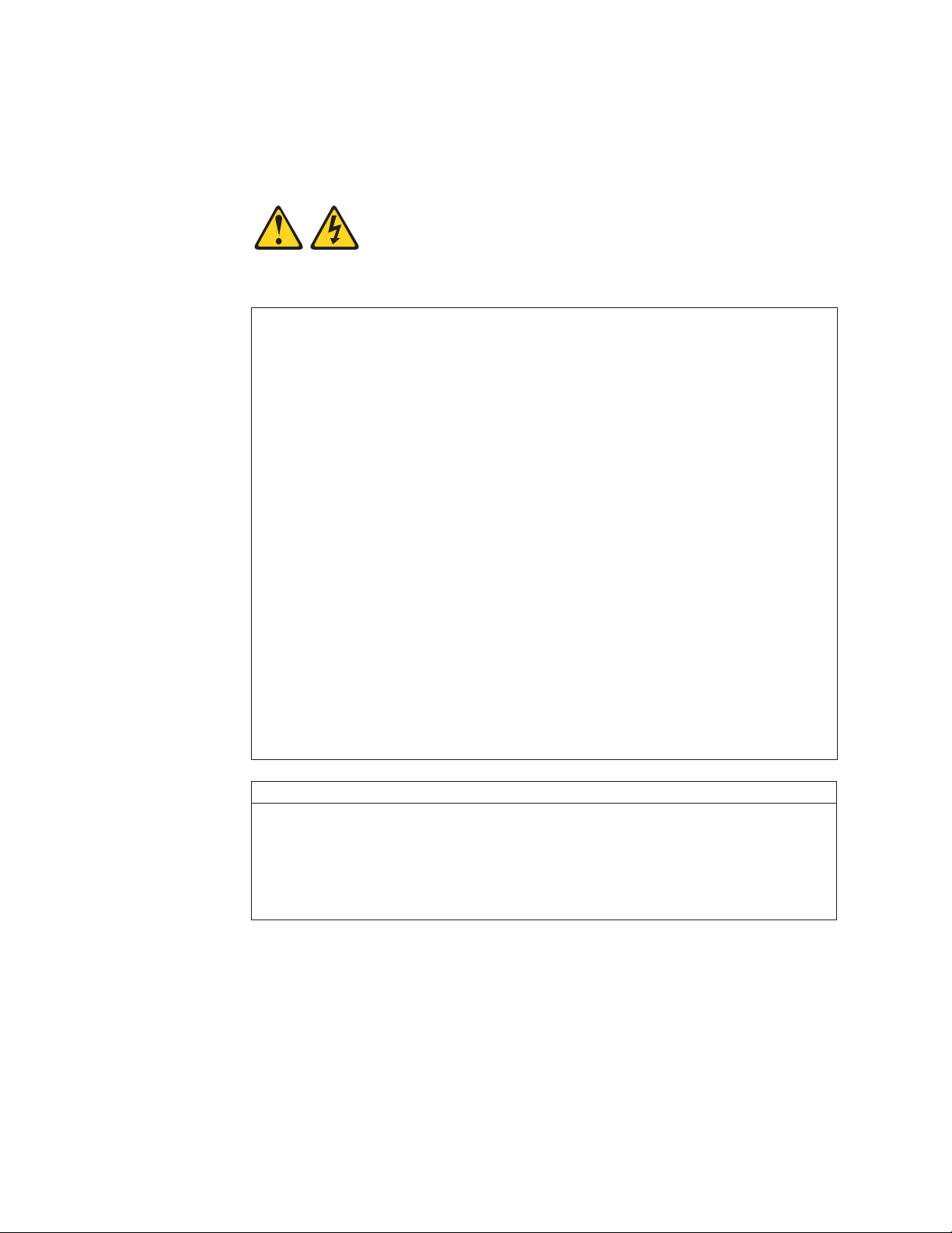
Statement 1:
DANGER
Electrical
current from power, telephone, and communication cables is
hazardous.
To avoid a shock hazard:
v Do not connect or disconnect any cables or perform installation,
maintenance, or reconfiguration of this product during an electrical
storm.
v Connect all power cords to a properly wired and grounded electrical
outlet.
v Connect to properly wired outlets any equipment that will be attached to
this product.
v When possible, use one hand only to connect or disconnect signal
cables.
v Never turn on any equipment when there is evidence of fire, water, or
structural damage.
v Disconnect the attached power cords, telecommunications systems,
networks, and modems before you open the device covers, unless
instructed otherwise in the installation and configuration procedures.
v Connect and disconnect cables as described in the following table when
installing, moving, or opening covers on this product or attached
devices.
To Connect: To Disconnect:
1. Turn everything OFF.
2. First, attach all cables to devices.
3. Attach signal cables to connectors.
4. Attach power cords to outlet.
1. Turn everything OFF.
2. First, remove power cords from outlet.
3. Remove signal cables from connectors.
4. Remove all cables from devices.
5. Turn device ON.
xii IBM TotalStorage DS4000 EXP700 and EXP710 Storage Expansion Enclosures: Installation, User’s, and Maintenance Guide
Page 15
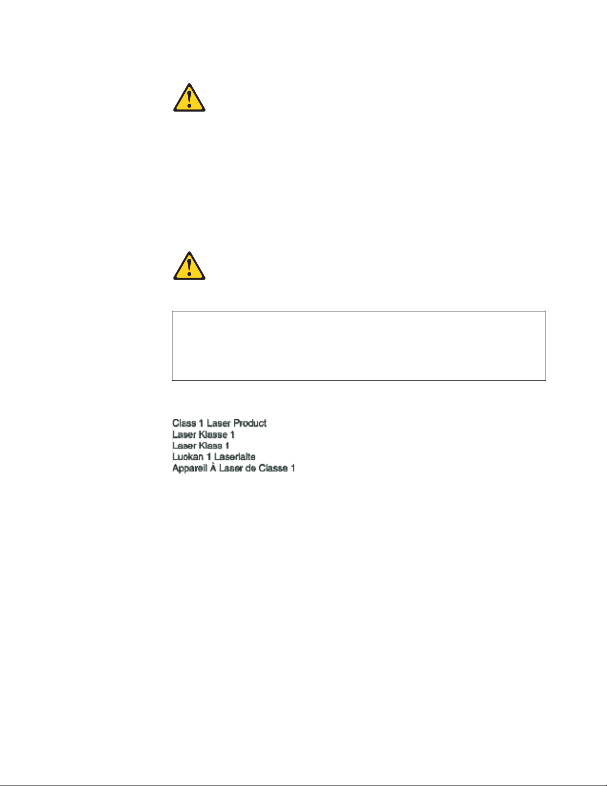
Statement 3:
CAUTION:
When laser products (such as CD-ROMs, DVD drives, fiber optic devices, or
transmitters) are installed, note the following:
v Do not remove the covers. Removing the covers of the laser product could
result in exposure to hazardous laser radiation. There are no serviceable
parts inside the device.
v Use of controls or adjustments or performance of procedures other than
those specified herein might result in hazardous radiation exposure.
DANGER
laser products contain an embedded Class 3A or Class 3B laser
Some
diode. Note the following.
Laser radiation when open. Do not stare into the beam, do not view directly
with optical instruments, and avoid direct exposure to the beam.
Class 1 Laser statement
IEC 825-11993 CENELEC EN 60 825
Safety xiii
Page 16
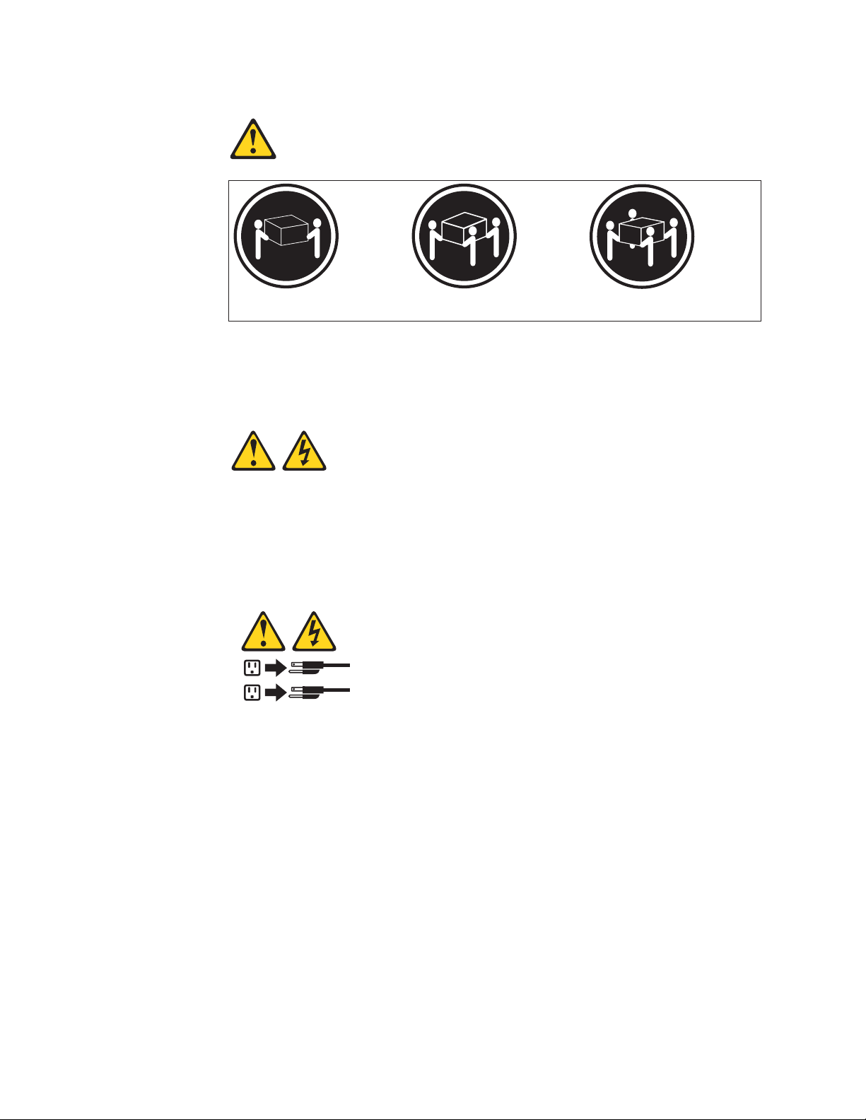
Statement 4:
≥ 18 kg (39.7 lb) ≥ 32 kg (70.5 lb) ≥ 55 kg (121.2 lb)
CAUTION:
Use safe practices when lifting.
Statement 5:
CAUTION:
The power control button on the device and the power switch on the power
supply do not turn off the electrical current supplied to the device. The device
also might have more than one power cord. To remove all electrical current
from the device, ensure that all power cords are disconnected from the power
source.
2
1
xiv IBM TotalStorage DS4000 EXP700 and EXP710 Storage Expansion Enclosures: Installation, User’s, and Maintenance Guide
Page 17
Statement 8:
CAUTION:
Never remove the cover on a power supply or any part that has the following
label attached.
Hazardous voltage, current, and energy levels are present inside any
component that has this label attached. There are no serviceable parts inside
these components. If you suspect a problem with one of these parts, contact
a service technician.
Safety xv
Page 18

xvi IBM TotalStorage DS4000 EXP700 and EXP710 Storage Expansion Enclosures: Installation, User’s, and Maintenance Guide
Page 19

About this document
This document provides instructions for installing and customizing the configuration
of your IBM
®
1RX) and DS4000 EXP710 (Machine Type 1740, Model 710) Storage Expansion
Enclosures. It also provides hardware maintenance and troubleshooting information.
FAStT product renaming
IBM is in the process of renaming some FAStT family products. Table 1 identifies
each new DS4000 product name with its corresponding FAStT product name. Note
that this change of product name only indicates no change in functionality or
warranty. All products listed below with new names are functionally-equivalent and
fully-interoperable. Each DS4000 product retains full IBM service as outlined in
service contracts issued for analogous FAStT products.
Table 1. Mapping of FAStT names to DS4000 Series names
Current FAStT Product Name New DS4000 Product Name
IBM TotalStorage FAStT Storage Server IBM TotalStorage DS4000
FAStT DS4000
FAStT Family DS4000 Mid-range Disk System
FAStT Storage Manager vX.Y (for example
v9.10)
FAStT100 DS4100
FAStT600 DS4300
FAStT600 with Turbo Feature DS4300 Turbo
FAStT700 DS4400
FAStT900 DS4500
EXP700 DS4000 EXP700
EXP710 DS4000 EXP710
EXP100 DS4000 EXP100
FAStT FlashCopy FlashCopy for DS4000
FAStT VolumeCopy VolumeCopy for DS4000
FAStT Remote Mirror (RM) Enhanced Remote Mirroring for DS4000
FAStT Synchronous Mirroring Metro Mirroring for DS4000
TotalStorage
®
DS4000 EXP700 (Machine Type 1740, Models 1RU,
DS4000 Storage Manager vX.Y (for example
v9.10)
Global Copy for DS4000
(New Feature = Asynchronous Mirroring
without Consistency Group)
Global Mirroring for DS4000
(New Feature = Asynchronous Mirroring with
Consistency Group)
Who should read this document
This document is intended for system operators and service technicians who have
extensive knowledge of fibre channel and network technology.
© Copyright IBM Corp. 2005 xvii
Page 20

How this document is organized
Chapter 1, “Introduction,” on page 1 describes the IBM TotalStorage DS4000
EXP700 and DS4000 EXP710 storage expansion enclosures. This chapter includes
an inventory checklist and an overview of the storage expansion enclosure features,
operating specifications, and components.
Chapter 2, “Installing and cabling the storage expansion enclosure,” on page 17
contains the instructions to install the storage expansion enclosure in a standard
rack cabinet, setting the interface options, cabling the storage expansion enclosure,
and power cord routing. In addition, this chapter contains instructions for turning on
and turning off the storage expansion enclosure during normal and emergency
situations.
Chapter 3, “Installing and replacing devices,” on page 67 contains step-by-step
instructions for installing and removing customer replaceable units (CRUs), such as
hard disk drives, power supplies, environmental service modules (ESMs), and fan
units.
Chapter 4, “Hardware maintenance,” on page 77 contains problems, symptoms, and
error messages that are specific to your storage expansion enclosure.
Appendix A, “Records,” on page 83 provides a table to record and update important
information about your storage expansion enclosure, including serial number and
device records. Whenever you add options to your storage expansion enclosure, be
sure to update the information in this appendix.
Appendix B, “Upgrading ESMs with the DS4000 EXP700 Models 1RU/1RX
Switched-ESM Option Upgrade Kit,” on page 85 provides instructions for upgrading
your DS4000 EXP700s with ESMs that have the same internal switched capabilities
as the DS4000 EXP710. The ESM upgrade is a feature of the DS4000 EXP700
Models 1RU/1RX Switched-ESM Option Upgrade Kit (P/N 25R0166).
Appendix C, “Upgrading the controller firmware for DS4300, DS4400, and DS4500
(DS4000 EXP710 only),” on page 93 provides instructions for performing the
manual firmware upgrade required if you are attaching one or more DS4000
EXP710s to a DS4400 or DS4500 storage server. The manual firmware upgrade is
also required if you are attaching one or more DS4000 EXP710s to a DS4300
without any internal hard disk drives.
Appendix D, “Power cords,” on page 101 lists power cord information for the
storage expansion enclosure.
Appendix E, “Accessibility,” on page 103 provides information about DS4000
Storage Manager accessibility features.
“Notices” on page 105 provides product notices.
Notices and statements used in this document
The caution and danger statements used in this document also appear in the
multilingual Safety Information document provided with your IBM TotalStorage
DS4000 EXP700 or DS4000 EXP710 storage expansion enclosure. Each caution
and danger statement is numbered for easy reference to the corresponding
statements in the safety document.
xviii IBM TotalStorage DS4000 EXP700 and EXP710 Storage Expansion Enclosures: Installation, User’s, and Maintenance
Guide
Page 21

The following types of notices and statements are used in this document:
v Note: These notices provide important tips, guidance, or advice.
v Important: These notices provide information or advice that might help you avoid
inconvenient or problem situations.
v Attention: These notices indicate possible damage to programs, devices, or
data. An attention notice is placed just before the instruction or situation in which
damage could occur.
v Caution: These statements indicate situations that can be potentially hazardous
to you. A caution statement is placed just before the description of a potentially
hazardous procedure step or situation.
v Danger: These statements indicate situations that can be potentially lethal or
extremely hazardous to you. A danger statement is placed just before the
description of a potentially lethal or extremely hazardous procedure step or
situation.
Figures used in this document
The figures used in this document are for illustrative purposes only. In some cases,
the actual device might look different from the figure. This applies particularly in
cases where the DS4000 EXP710 differs from the DS4000 EXP700.
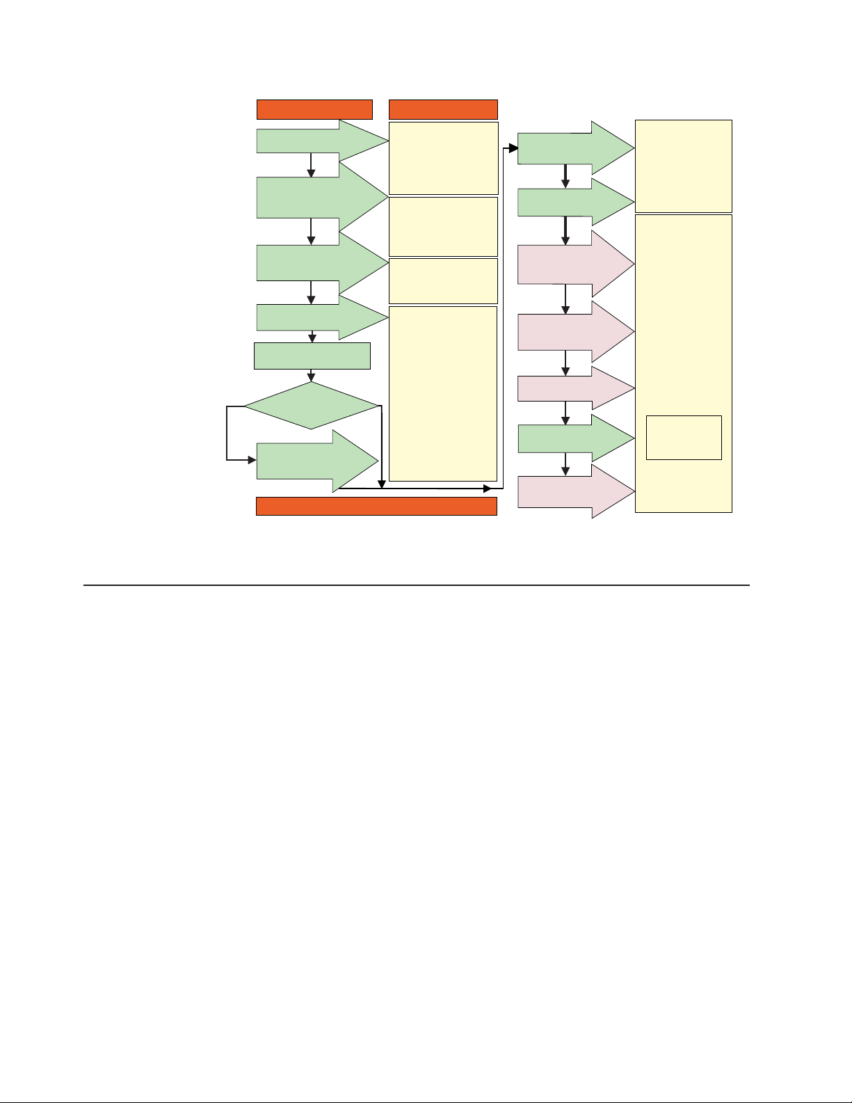
DS4000 installation process overview
The following flow chart gives an overview of the DS4000 hardware and the
DS4000 Storage Manager software installation process. Lined arrows in the flow
chart indicate consecutive steps in the hardware and software installation process.
Labeled arrows indicate which current documents provide detailed information about
those steps.
About this document xix
Page 22
Install Process Documentation
Plan installation
Install Storage
Server/RAID Controller
Enclosure(s) in Rack
Install Storage
Expansion Unit(s)
* FC Planning and
Integration: User's Guide
and Svc Info
DS4000 Storage Manager
Concepts Guide
DS4000 Storage Svr
Installation Guide
DS4000 RAID Controller
Enclosure Unit Install
and User's Guide
DS4000 Storage Exp Units
Install and User's Guides
Connect Power and
Start Server
Verify Server
operation w/ LEDs
Prepare for
Installation of
SM Software
DS4000 Storage Server
Installation Guide
DS4000 Hardware
Maintenance Manual
DS4000 Problem
Determination Guide
DS4000 Storage
Manager Installation
and Support
OS Guides
Make FC Connections
SET Link Speed
Out-of-Band
Install Network
Hardware; Prep are
Network Connection
* For pSeries Server and 6227 or 6228 HBA use only
(1GB or 2GB)
Determine
Management
Method
In-Band
DS4000 and HBA Install
and User's Guides
DS4000 Fibre Channel
Installation Guides
Fibre Channel Cabling
Figure 1. Installation process flow by current publications
DS4000 Storage Server publications
The following tables present an overview of the DS4500, DS4400, DS4300 Fibre
Channel, and DS4100 SATA Storage Server product libraries, as well as other
related documents. Each table lists documents that are included in the libraries and
what common tasks they address.
You can access the documents listed in these tables at one of the following Web
sites:
Storage Server
Instructions
Install and Verify
SM SW on Host and
Workstation
Complete SM SW
Installation
Configure Storage
Hardware
Configure Storage
Subsystems on Host
DS4000 Storage Manager
Copy Services
User's Guide
Online Help
sj001046
www.ibm.com/servers/storage/support/disk/
www.ibm.com/shop/publications/order/
DS4500 storage server library
Table 2 on page xxi associates each document in the DS4500 (previously
FAStT900) storage server library with its related common user tasks.
xx IBM TotalStorage DS4000 EXP700 and EXP710 Storage Expansion Enclosures: Installation, User’s, and Maintenance Guide
Page 23

Table 2. TotalStorage DS4500 Fibre Channel Storage Server document titles by user tasks
Title User Tasks
Planning Hardware
Installation
Software
Installation
Configuration Operation and
Administration
IBM TotalStorage
DS4500 Installation
and Support Guide,
U U U
GC26-7727
IBM TotalStorage
DS4500 Fibre
Channel Cabling
U U
Instructions,
GC26-7729
IBM TotalStorage
DS4500 Storage
Server User’s
U U U
Guide, GC26-7726
IBM TotalStorage
DS4500 Rack
Mounting
U U
Instructions,
GC26-7728
Diagnosis and
Maintenance
About this document xxi
Page 24

DS4400 storage server library
Table 3 associates each document in the DS4400 (previously FAStT700) storage
server library with its related common user tasks.
Table 3. TotalStorage DS4400 Fibre Channel Storage Server document titles by user tasks
Title User Tasks
IBM DS4400 Fibre
Channel Storage
Server User’s
Guide, GC26-7730
IBM DS4400 Fibre
Channel Storage
Server Installation
and Support Guide,
GC26-7731
IBM DS4400 Fibre
Channel Cabling
Instructions,
GC26-7732
Planning Hardware
Installation
U U U U U
U U U U
U U
Software
Installation
Configuration Operation and
Administration
Diagnosis and
Maintenance
xxii IBM TotalStorage DS4000 EXP700 and EXP710 Storage Expansion Enclosures: Installation, User’s, and Maintenance Guide
Page 25

DS4300 storage server library
Table 4 associates each document in the DS4300 (previously FAStT600) storage
server library with its related common user tasks.
Table 4. TotalStorage DS4300 Fibre Channel Storage Server document titles by user tasks
Title User Tasks
IBM TotalStorage
DS4300 Fibre
Channel Storage
Server Installation
and User’s Guide,
GC26-7722
IBM TotalStorage
DS4300 Rack
Mounting
Instructions,
GC26-7724
IBM TotalStorage
DS4300 Fibre
Channel Cabling
Instructions,
GC26-7725
IBM TotalStorage
DS4300 SCU Base
Upgrade Kit,
GC26-7740
IBM TotalStorage
DS4300 SCU Turbo
Upgrade Kit,
GC26-7741
IBM TotalStorage
DS4300 Turbo
Models 6LU/6LX
Upgrade Kit,
GC26-7723
Planning Hardware
Installation
U U U
U U
U U
U U
U U
U U
Software
Installation
Configuration Operation and
Administration
Diagnosis and
Maintenance
About this document xxiii
Page 26

DS4100 storage server library
Table 5 associates each document in the DS4100 (previously FAStT100) storage
server library with its related common user tasks.
Table 5. TotalStorage DS4100 SATA Storage Server document titles by user tasks
Title User Tasks
IBM TotalStorage
DS4100 Installation,
User’s and
Maintenance Guide,
GC26-7733
IBM TotalStorage
DS4100 Cabling
Guide, 24P8973
Planning Hardware
Installation
U U U U U
U
Software
Installation
Configuration Operation and
Administration
Diagnosis and
Maintenance
xxiv IBM TotalStorage DS4000 EXP700 and EXP710 Storage Expansion Enclosures: Installation, User’s, and Maintenance
Guide
Page 27

DS4000 Storage Manager Version 9 publications
Table 6 associates each document in the DS4000 Storage Manager (previously
FAStT Storage Manager) library with its related common user tasks.
Table 6. TotalStorage DS4000 Storage Manager Version 9 titles by user tasks
Title User tasks
IBM TotalStorage
DS4000 Storage
Manager Version 9
Installation and
Support Guide for
Windows
2000/Server 2003,
NetWare, ESX
Server, and Linux,
GC26-7706
IBM TotalStorage
DS4000 Storage
Manager Version 9
Installation and
Support Guide for
AIX, UNIX, Solaris
and Linux on
POWER,
GC26-7705
IBM TotalStorage
DS4000 Storage
Manager Version 9
Copy Services
User’s Guide,
GC26-7707
IBM TotalStorage
DS4000 Storage
Manager Version 9
Concepts Guide,
GC26-7734
Planning Hardware
installation
U U U
U U U
U U U U
U U U U U U
Software
installation
Configuration Operation and
administration
Diagnosis and
maintenance
About this document xxv
Page 28

Other DS4000 and DS4000-related documents
Table 7 associates each of the following documents with its related common user
tasks.
Table 7. TotalStorage DS4000 and DS4000–related document titles by user tasks
Title User Tasks
IBM Safety
Information,
P48P9741
IBM TotalStorage
DS4000 Quick Start
Guide, GC26-7738
IBM TotalStorage
DS4000 Hardware
Maintenance
Manual,GC26-7702
IBM TotalStorage
DS4000 Problem
Determination
Guide, GC26-7703
IBM Fibre Channel
Planning and
Integration: User’s
Guide and Service
Information,
SC23-4329
IBM TotalStorage
DS4000 FC2-133
Host Bus Adapter
Installation and
User’s Guide,
GC26-7736
IBM TotalStorage
DS4000 FC2-133
Dual Port Host Bus
Adapter Installation
and User’s Guide,
GC26-7737
IBM TotalStorage
DS4000 Fibre
Channel and Serial
ATA Intermix
Premium Feature
Installation Overview
GC26-7713
Fibre Channel
Solutions - IBM
DS4000 FAStT
EXP500 Installation
and User’s Guide,
59p5637
Planning Hardware
Installation
U U
U U U U
U U
U U
U U U U
U U U U U
Software
Installation
Configuration Operation and
Administration
U
Diagnosis and
Maintenance
U
U
xxvi IBM TotalStorage DS4000 EXP700 and EXP710 Storage Expansion Enclosures: Installation, User’s, and Maintenance
Guide
Page 29

Table 7. TotalStorage DS4000 and DS4000–related document titles by user tasks (continued)
Title User Tasks
Planning Hardware
Installation
Software
Installation
Configuration Operation and
Administration
IBM TotalStorage
DS4000 EXP700
and EXP710
Storage Expansion
Enclosures
U U U U U
Installation, User’s,
and Maintenance
Guide, GC26-7735
IBM TotalStorage
DS4000 Hard Drive
and Storage
Expansion
Enclosures
U U
Installation and
Migration Guide,
GC26-7704
IBM DS4000
Management Suite
Java User’s Guide,
32P0081
®
IBM Netfinity
Channel Cabling
Instructions,
Fibre
U
19K0906
IBM Fibre Channel
SAN Configuration
Setup Guide,
U U U U
25P2509
Diagnosis and
Maintenance
U U
Getting information, help, and service
If you need help, service, or technical assistance or just want more information
about IBM products, you will find a wide variety of sources available from IBM to
assist you. This section contains information about where to go for additional
information about IBM and IBM products, what to do if you experience a problem
with your IBM Eserver xSeries
®
service, if it is necessary.
Before you call
Before you call, make sure that you have taken these steps to try to solve the
problem yourself:
v Check all cables to make sure that they are connected.
v Check the power switches to make sure that the system is turned on.
v Use the troubleshooting information in your system documentation and use the
diagnostic tools that come with your system.
v Check for technical information, hints, tips, and new device drivers at the
following Web site:
www.ibm.com/servers/storage/support/disk/
v Use an IBM discussion forum on the IBM Web site to ask questions.
or IntelliStation
®
system, and whom to call for
About this document xxvii
Page 30

You can solve many problems without outside assistance by following the
troubleshooting procedures that IBM provides in the online help or in the documents
that are provided with your system and software. The information that comes with
your system also describes the diagnostic tests that you can perform. Most xSeries
and IntelliStation systems, operating systems, and programs come with information
that contains troubleshooting procedures and explanations of error messages and
error codes. If you suspect a software problem, see the information for the
operating system or program.
Using the documentation
Information about the xSeries or IntelliStation system and preinstalled software, if
any, is available in the documents that come with your system. This includes printed
documents, online documents, readme files, and help files. See the troubleshooting
information in your system documentation for instructions on how to use the
diagnostic programs. The troubleshooting information or the diagnostic programs
might tell you that you need additional or updated device drivers or other software.
Web sites
IBM maintains pages on the World Wide Web where you can get the latest
technical information and download device drivers and updates.
v For DS4000 information, go to the following Web site:
www.ibm.com/servers/storage/support/disk/
The support page has many sources of information and ways for you to solve
problems, including:
– Diagnosing problems using the IBM Online Assistant
– Downloading the latest device drivers and updates for your products
– Viewing frequently asked questions (FAQ)
– Viewing hints and tips to help you solve problems
– Participating in IBM discussion forums
– Setting up e-mail notification of technical updates about your products
Yo u can order publications through the IBM Publications Ordering System at the
v
following web site:
www.elink.ibmlink.ibm.com/public/applications/publications/cgibin/pbi.cgi/
v For the latest information about IBM xSeries products, services, and support, go
to the following Web site:
www.ibm.com/eserver/xseries/
v For the latest information about IBM pSeries
to the following Web site:
www.ibm.com/eserver/pseries/
v For the latest information about the IBM IntelliStation information, go to the
following Web site:
www.ibm.com/pc/intellistation/
v For the latest information about operating system and HBA support, clustering
support, SAN fabric support, and Storage Manager feature support, see the
TotalStorage DS4000 Interoperability Matrix at the following Web site:
www.ibm.com/servers/storage/disk/ds4000/interop-matrix.html
®
products, services, and support, go
Software service and support
Through IBM Support Line, for a fee you can get telephone assistance with usage,
configuration, and software problems with xSeries servers, IntelliStation
xxviii IBM TotalStorage DS4000 EXP700 and EXP710 Storage Expansion Enclosures: Installation, User’s, and Maintenance
Guide
Page 31

workstations, and appliances. For information about which products are supported
by Support Line in your country or region, go to the following Web site:
www.ibm.com/services/sl/products/
For more information about the IBM Support Line and other IBM services, go to the
following Web sites:
v www.ibm.com/services/
v www.ibm.com/planetwide/
Hardware service and support
You can receive hardware service through IBM Integrated Technology Services or
through your IBM reseller, if your reseller is authorized by IBM to provide warranty
service. Go to the following Web site for support telephone numbers:
www.ibm.com/planetwide/
In the U.S. and Canada, hardware service and support is available 24 hours a day,
7 days a week. In the U.K., these services are available Monday through Friday,
from 9 a.m. to 6 p.m.
Fire suppression systems
A fire suppression system is the responsibility of the customer. The customer’s own
insurance underwriter, local fire marshal, or a local building inspector, or both,
should be consulted in selecting a fire suppression system that provides the correct
level of coverage and protection. IBM designs and manufactures equipment to
internal and external standards that require certain environments for reliable
operation. Because IBM does not test any equipment for compatibility with fire
suppression systems, IBM does not make compatibility claims of any kind nor does
IBM provide recommendations on fire suppression systems.
“Storage expansion enclosure operating specifications” on page 13 lists the
environmental specifications for the EXP700 and EXP710.
How to send your comments
Your feedback is important in helping us to provide the most accurate and
high-quality information. If you have comments or suggestions for improving this
publication, you can send us comments electronically by using these addresses:
v Internet: starpubs@us.ibm.com
™
v IBMLink
v IBMLink from Canada: STARPUBS at TORIBM
v IBM Mail Exchange: USIB3WD at IBMMAIL
from U.S.A.: STARPUBS at SJEVM5
can also mail your comments by using the Reader Comment Form in the back
You
of this manual or direct your mail to
International Business Machines Corporation
Information Development
Dept. GZW
9000 South Rita Road
Tucson, AZ 85744–0001
U.S.A.
About this document xxix
Page 32

xxx IBM TotalStorage DS4000 EXP700 and EXP710 Storage Expansion Enclosures: Installation, User’s, and Maintenance Guide
Page 33

Chapter 1. Introduction
This chapter describes the IBM TotalStorage DS4000 EXP700 and DS4000
EXP710 storage expansion enclosure operating specifications, features, and
components. This chapter also includes a list of hardware that comes with the
storage expansion enclosure.
Throughout this document, the IBM TotalStorage DS4000 EXP700 storage
Note:
expansion enclosure is referred to as the DS4000 EXP700. The IBM
TotalStorage DS4000 EXP710 storage expansion enclosure is referred to as
the DS4000 EXP710. When information in this document applies to both the
DS4000 EXP700 and DS4000 EXP710, the generic term storage expansion
enclosure is used.
Overview
The IBM TotalStorage DS4000 EXP700 (Machine Type 1740, Models 1RU and
1RX) and DS4000 EXP710 (Machine Type 1740, Model 710) storage expansion
enclosures provide high-capacity, fibre channel disk storage. Both storage
expansion enclosures deliver fast, high-volume data transfer, retrieval, and storage
functions for multiple drives, to multiple hosts. The storage expansion enclosures
provide continuous, reliable service, using hot-swap technology for easy
replacement without shutting down the system. Both the DS4000 EXP700 and
DS4000 EXP710 support redundant, dual-loop configurations. External cables and
Small Form-Factor Pluggable (SFP) modules connect the controller to the storage
expansion enclosure.
The DS4000 EXP710 Fibre Channel storage expansion enclosure provides
improved reliability and efficiency, utilizing internal switch technology to attach to
each disk drive within the DS4000 EXP710 storage expansion enclosure. Within the
DS4000 EXP710, the redundant environmental service modules (ESMs) utilize a
fibre channel switched technology attaching directly to each of the dual ported disk
drive modules for additional redundancy and high availability.
1
The DS4000 EXP710 fibre channel storage expansion enclosure offers the following
diagnostic and performance benefits:
v Improved diagnostic capabilities
– Provides full isolation of drives
– Eliminates the risk of a single drive disrupting the loop, causing other drives
on the loop to fail
– Enables selective diagnosis of fibre channel errors
– Provides a platform for future enhanced diagnostic and serviceability
capabilities
v Performance
1. The DS4000 EXP710 uses switched JBOD (or switched storage expansion enclosure) technology to enable an enhanced version
of the 2 Gb/s fibre channel JBOD. The primary difference between a switched JBOD and a JBOD is that the switched JBOD
contains a fibre channel ″Loop Switch″ Application-Specific Integrated Circuit (ASIC). The Loop Switch ASIC allows the switched
JBOD drives and any connected initiator to operate as though they were on a private Fibre Channel Arbitrated Loop (FC-AL), while
retaining the performance and diagnostic advantages of fibre channel fabric. The Loop Switch ASIC allows FC-AL devices to
communicate directly with each other using a non-blocking crossbar switch, which reduces the loop latency inherent in a true
arbitrated loop. Because fibre channel communication is essentially point-to-point with the Loop Switch ASIC, diagnosis and
isolation of loop problems is greatly simplified. The advent of switched JBOD storage expansion enclosures is expected to be a
significant improvement in fibre channel based storage diagnostic and performance.
© Copyright IBM Corp. 2005 1
Page 34

– Improves performance in large configurations by reducing node delays (loop
latency)
– Drive isolation frees up bandwidth to improve drive rebuild times
DS4000 EXP710 is currently supported by DS4300 Turbo Option, DS4400, and
The
DS4500 storage servers only. Additional DS4000 storage server support for the
DS4000 EXP710 might be available in the future. Contact your IBM reseller or
representative for more information.
Attention
Before you attach the DS4000 EXP710 to a supported storage server, you
must verify that the controller firmware is updated to firmware version
6.10.xx.xx or later. This firmware is provided with Storage Manager 9.1 and
must be installed before attaching the DS4000 EXP710.
Storage Manager 9.1 software and the controller firmware version 6.10.xx.xx
can be downloaded from the DS4000 support Web site:
www.ibm.com/servers/storage/support/disk/
Upgrading your DS4000 EXP700s
The DS4000 EXP700 Models 1RU/1RX Switched-ESM Option Upgrade Kit (P/N
25R0166) is available to upgrade DS4000 EXP700s in existing configurations with
ESMs that have the same internal switched capabilities as the DS4000 EXP710.
The ESM upgrade process is described in this document in Appendix B, “Upgrading
ESMs with the DS4000 EXP700 Models 1RU/1RX Switched-ESM Option Upgrade
Kit,” on page 85.
Attention: Do not dispose of the DS4000 EXP700 ESMs you replace with the
ESMs in the upgrade kit. Refer to the separate instructions included with the
upgrade kit for return processing information for the DS4000 EXP700 ESMs you are
replacing.
The upgrade option is not available for storage expansion enclosures
Note:
connected to FAStT200 or FAStT500 storage servers. Additionally, the
upgrade option cannot be used to upgrade DS4000 EXP700 storage
expansion enclosures connected to DS4000 storage servers that are
configured with drive loops that intermix FAStT EXP500 and DS4000
EXP700 storage expansion enclosures.
Intermixing DS4000 EXP700s with DS4000 EXP710s and other storage expansion enclosures
You can connect multiple DS4000 EXP700s or DS4000 EXP710s together to
support a large number of disk drives on a fibre channel loop. You can also intermix
DS4000 EXP700s and DS4000 EXP710s together in a fibre channel drive loop.
However, when intermixing DS4000 EXP700s and DS4000 EXP710s in a fibre
channel drive loop, the DS4000 EXP710s must be grouped together. The minimum
ESM firmware requirement for intermixing DS4000 EXP700s or DS4000 EXP710s
is version 9326. For more information, see “Intermixing DS4000 EXP700s and
DS4000 EXP710s in the same loop” on page 44.
2 IBM TotalStorage DS4000 EXP700 and EXP710 Storage Expansion Enclosures: Installation, User’s, and Maintenance Guide
Page 35

You can intermix DS4000 EXP700s with FAStT EXP500s in a fibre channel loop.
You cannot intermix DS4000 EXP710s with FAStT EXP500s in a fibre channel loop.
When you attach DS4000 EXP710 storage expansion enclosures, you must remove
any 1 Gb/s FAStT EXP500 storage expansion enclosures from the drive loop and
you must set the fibre channel speed of the drive loop to 2 Gb/s. See “Connecting
storage expansion enclosures in a loop with FAStT EXP500s (DS4000 EXP700
only)” on page 50.
You can intermix DS4000 EXP100s with DS4000 EXP700s or DS4000 EXP710s in
the same DS4000 Storage Server configuration. You must purchase the FC/SATA
Enclosure Intermix premium option to combine DS4000 EXP100s with DS4000
EXP700s or DS4000 EXP710s in the same storage server configuration. To attach
DS4000 EXP100s or DS4000 EXP710s storage expansion enclosures to a storage
server, the storage server controller firmware must be at version 06.xx.xx.xx or
higher. In addition, the minimum ESM firmware requirement for intermixing DS4000
EXP700s or DS4000 EXP710s with DS4000 EXP100s is version 9554. See
“Intermixing DS4000 EXP700s or DS4000 EXP710s with DS4000 EXP100s in the
same loop” on page 52
Fibre channel defined
Fibre channel technology is outlined in the SCSI-3 Fibre Channel Protocol
(SCSI-FCP) standard. Fibre channel is a high-speed data transport technology used
for mass storage and networking.
Using a Fibre Channel Arbitrated loop (FC-AL), more than 100 fibre channel
devices can be supported, compared to 15 small computer system interface (SCSI)
devices.
The DS4000 EXP700 and DS4000 EXP710 are 2 Gb/s fibre channel devices that
support data transfer rates up to 200 MB per second half-duplex and 400 MB per
second full-duplex on optical interfaces.
Product updates
Download the latest version of the DS4000 Storage Manager host software and the
any appropriate DS4000 product series firmware at the time of the initial installation
and when product updates become available.
To be notified of important product updates, you must first register at the IBM
Support and Download Web site:
www.ibm.com/support/us/
Important
In order to keep your system up to date with the latest firmware and other
product updates, use the information below to register and use the My
support web site.
Go to the Personalized Support section of the web page and click My support.
On the next page, if you have not already done so, register to use the site by
clicking register now.
Perform the following steps to receive product updates:
Chapter 1. Introduction 3
Page 36

1. After you have registered, type your user ID and password to log into the site.
The My support page opens.
2. Click add products. Using the pull downs in the Products area, select Storage
→ Computer Storage → Disk Storage Systems → TotalStorage DS4000
Midrange Disk Systems & FAStT Stor Srvrs.
3. Place a check in the box for the machine type of your DS4000 series product,
as well as any other attached DS4000 series product(s) for which you would like
to receive information. Select Add products. The My support page reopens.
4. Select Subscribe to email. In the Documents area on the next page, use the
pull down and select Storage.
5. On the next page, place a check in the following boxes:
a. Please send these documents by weekly email
b. Downloads and drivers
c. Flashes
and any others you may be interested in, and then click Update.
Inventory checklist
The storage expansion enclosure comes with the following items:
v Hardware
– Power cables
Two line cord jumpers
–
– One rack-mounting hardware kit
– Two rails (right and left assembly)
– Te n M6 black hex-head screws
– Te n M6 cage nuts
– 14 drive blank trays (shipped inside the storage expansion enclosure)
Documentation
v
– IBM TotalStorage DS4000 EXP700 and EXP710 Storage Expansion
– IBM Safety Information
– Rack Mounting Template
– IBM License Agreement for Machine Code
– Statement of Limited Warranty
- DS4000 EXP700 Model 1RU: Two U.S. power cables
- DS4000 EXP700 Model 1RX: None
- DS4000 EXP710 Model 710: None
Your storage expansion enclosure ships with 14 hard disk drives; any drive
bays not containing hard disk drives will contain blank drive trays. Each of the
14 drive bays must always contain either a blank tray or a hard disk drive.
Enclosures Installation, User’s, and Maintenance Guide
To connect your storage expansion enclosure to other devices, use the following
options:
v IBM Small Form-Factor Pluggable (SFP) module
v IBM LC-LC Fibre Channel cable
DS4000 EXP700 only: Depending on your configuration, you might also need
For
the following options:
4 IBM TotalStorage DS4000 EXP700 and EXP710 Storage Expansion Enclosures: Installation, User’s, and Maintenance Guide
Page 37

v IBM LC-SC Fibre Channel Cable Adapter
v Gigabit Interface Converter (GBIC)
Note: For some storage expansion enclosure models, you must order these
options separately.
Storage expansion enclosure components
The storage expansion enclosure has the following removable components, called
customer replaceable units (CRUs). All CRUs are accessible from the front or back
of the storage expansion enclosure.
v DS4000 2 Gb/s fibre channel hard disk drives
v Environmental service modules (ESMs) (comes with two)
The DS4000 EXP700 and EXP710 ESMs are not interchangeable. In
Note:
addition, you cannot mix DS4000 EXP700 and EXP710 ESMs in the same
storage expansion enclosure. Always verify that you have the correct FRU
P/N before you order replacement ESMs or insert replacement ESMs in
the storage expansion enclosure.
v Power supplies (comes with two)
v Fans (comes with two)
The figures used in this document are for illustrative purposes only. In some
Note:
cases, the actual device might look different from the figure. This applies
particularly in cases where the DS4000 EXP710 differs from the DS4000
EXP700.
Storage expansion enclosure bays
This section shows the location of storage expansion enclosure hot-swap CRU bays
and describes the functionality of each CRU. The hot-swap features of the storage
expansion enclosure enable you to remove and replace DS4000 2 Gb/s fibre
channel hard disk drives, power supplies, ESMs, and fan units without turning off
the storage expansion enclosure. Yo u can maintain the availability of your system
while a hot-swap device is removed, installed, or replaced.
Hot-swap drive bays
The hot-swap drive bays that are accessible from the front of your storage
expansion enclosure are shown in Figure 2.
Hot-swap drive bays
Figure 2. Hot-swap drive bays
exp70001
Chapter 1. Introduction 5
Page 38

The storage expansion enclosure supports up to 14 DS4000 2 Gb/s fibre channel
hard disk drives or later versions. These drives come preinstalled in drive trays.
This drive-and-tray assembly is called a drive CRU. You install the drive CRUs in
the 14 drive bays on the front of the storage expansion enclosure.
Note: DS4000 2 Gb/s fibre channel hard disk drives must be used in the storage
expansion enclosure even if the system is set to a 1 Gb per second rate. 1
Gb/s hard disk drives are not supported.
Attention: Never hot-swap a drive CRU when its green Activity LED is flashing.
Hot-swap a drive CRU when its amber Fault LED is lit and not flashing or when the
drive is inactive and the green Activity LED is lit and not flashing.
If the drive is not in a failed state (as indicated by its lit amber LED), manually fail
the drive using the Storage Management client before attempting to remove it from
the drive slot.
Attention: After you remove a drive CRU, wait 70 seconds before replacing or
reseating the drive CRU to allow the drive to properly spin down. Failure to do so
may cause undesired events.
Fan, ESM, and power-supply bays
The location of the hot-swap fan bays, hot-swap ESM bays, and hot-swap power
supply bays are shown in Figure 3.
Hot-swap fan bays
ESM latches
ESM bays
1 Gb/s 2 Gb/s
Conflict
X10
X1
Tray Number
Hot-swap power
supply bays
exp70002
Figure 3. Hot-swap fan, ESM, and power supply bays
v Hot-swap fan bays: Your storage expansion enclosure comes with two
interchangeable hot-swap and redundant fan units. These two fan units are
located in the hot-swap fan bays. Each fan unit contains two fans. If one fan unit
fails, the second fan unit continues to operate. Both fan units must be installed to
maintain proper cooling within your storage expansion enclosure, even if one fan
unit is not operational.
Attention: The fans in your storage expansion enclosure draw in fresh air and
force out hot air. These fans are hot-swappable and redundant; however, when
one fan fails, the failed fan unit must be replaced within 48 hours to maintain
redundancy and optimum cooling. When you remove the failed unit, be sure to
install the replacement fan unit within 10 minutes to prevent overheating.
v ESM bays: Your storage expansion enclosure comes with two hot-swappable
ESMs, which are located in the ESM bays. The ESMs monitor the overall status
of the storage expansion enclosure. The DS4000 EXP700 ESMs provide a 1
6 IBM TotalStorage DS4000 EXP700 and EXP710 Storage Expansion Enclosures: Installation, User’s, and Maintenance Guide
Page 39

Gb/s or 2 Gb/s fibre channel interface to the DS4000 storage server drive loop
ports. The DS4000 EXP710 provides a 2 Gb/s fibre channel interface only to the
DS4000 storage server drive loop ports.
Attention: After you remove an ESM, wait 70 seconds before reseating or
replacing the ESM. Failure to do so may cause undesired events.
Each ESM has two SFP module connector ports for connecting your storage
expansion enclosure to the controller or connecting two or more storage
expansion enclosures together. The ESMs provide redundancy when both of
them are configured into redundant fibre channel loops. See your fibre channel
controller documentation to determine if the controller supports this redundancy
function.
The DS4000 EXP700 and EXP710 ESMs are not interchangeable. In
Note:
addition, you cannot mix DS4000 EXP700 and DS4000 EXP710 ESMs in
the same storage expansion enclosure. Always verify that you have the
correct FRU P/N before you order replacement ESMs or insert
replacement ESMs in the storage expansion enclosure.
Your storage expansion enclosure ESMs come with locking latches to secure the
ESMs to the storage expansion enclosure bays. The latch must be unlocked
before the ESM can be removed from the storage expansion enclosure.
v Hot-swap power-supply bays: Your storage expansion enclosure comes with
two hot-swap and redundant power supplies. The power supplies are located in
the hot-swap power-supply bays. Both power supplies must be installed in your
storage expansion enclosure, even if one power supply is not operational.
Front controls and indicators
This section describes the primary controls on the front of the storage expansion
enclosure. The location of these primary controls are shown in Figure 4.
Power-on LED
Figure 4. Front controls and indicators
v Drive Activity LED: Each drive CRU has a DriveActivity LED. When flashing,
this green LED indicates drive activity. When lit, this green LED indicates the
drive is properly installed and powered on.
v Blank tray: Storage expansion enclosures come with blank trays in the unused
drive bays. To begin installing new drives, you must first remove the blank trays
and save them. Each of the 14 bays must always contain either a blank tray or a
drive CRU to ensure proper air flow across the drives and to comply with
regulatory electromagnetic emission limits.
General system
error LED
Tray handle
Enclosure
Identity LED
Latch
Bezel
Fault LED
Blank tray
Drive CRU
Activity LED
exp70005
Chapter 1. Introduction 7
Page 40

v Drive CRU: Yo u can install up to 14 hot-swap drive CRUs in the storage
expansion enclosure.
v Drive Fault LED: Each drive CRU has a DriveFault LED. When lit, this amber
LED indicates a drive failure. When flashing, this amber LED indicates that a
drive identify or rebuild process is in progress.
v General system error LED: When lit, this amber LED indicates that the unit has
a power supply, fan unit, ESM, or hard disk drive error.
v Power-on LED: When lit, this green LED indicates that the storage expansion
enclosure has dc power.
v Enclosure identity LED: When lit, this blue LED indicates that the unit is being
identified by the controller. This LED is also lit when the devices that are part of a
fibre channel loop are identified.
Table 8 shows the Storage Manager and firmware versions required to support
enclosure identity LED activity for the different storage servers that support the
DS4000 EXP700 and DS4000 EXP710.
Table 8. Enclosure identity LED activity support requirements
Connected storage server Storage Manager version Firmware version
FAStT200, FAStT500, or DS4400 8.21 or later 5.21 or later
DS4300 8.33 or later 5.33 or later
DS4500 8.30 or later 5.30 or later
v Tray handle: Use this multipurpose handle to insert and remove a drive CRU in
the bay.
v Latch: This multipurpose blue latch releases or locks the drive CRU in place.
Rear controls, indicators, and connectors
Two hot-swap power-supply CRUs, two hot-swap fan CRUs, and two ESMs are
accessible from the back of the storage expansion enclosure. These components
contain several controls, indicators, and connectors.
Power-supply controls, indicators, and connectors
The storage expansion enclosure comes with two 400-Watt hot-pluggable,
redundant power supplies. Each power supply has a power and a fault LED located
on the back of the storage expansion enclosure. The green LED indicates that the
power supply is detecting ac power. The amber fault LED is lit if the power supply is
unable to deliver dc power. The storage expansion enclosure requires that both
power supplies be installed to meet Electromagnetic Compatibility (EMC) and
cooling requirements. Figure 5 on page 9 shows their locations.
8 IBM TotalStorage DS4000 EXP700 and EXP710 Storage Expansion Enclosures: Installation, User’s, and Maintenance Guide
Page 41

Levers
Power LEDs
Fault LEDs
Power switches
1 Gb/s 2 Gb/s
Conflict
X10
X1
Tray Number
AC power
connectors
Power supply CRUs
exp70006
Figure 5. Power-supply controls, indicators, and connectors
v Levers: When you remove or install a power supply CRU, the levers located at
the top of the power supply CRU must be unlocked.
v Power LEDs: These green power LEDs are lit when the storage expansion
enclosure is turned on and receiving ac power.
v Fault LED: The amber power-supply fault LED is lit if a power-supply failure
occurs.
v Power switches: The power switches are used to turn the power supplies on
and off. You must turn on both switches to use the redundant power supplies.
v AC power connectors: To provide ac power to the storage expansion enclosure,
power cables must be connected to the ac power connectors located on the back
of the storage expansion enclosure.
v Hot-swap power-supply CRUs: The two hot-swap power supplies are located
on the back of the storage expansion enclosure. Both power-supply CRUs must
be installed, even if one power supply is not working.
Fan controls and indicators
The storage expansion enclosure comes with two fan units. Each storage
expansion enclosure has two fans as shown in Figure 6 on page 10. The fan units
in your storage expansion enclosure are hot-swappable and redundant. One fan will
continue to operate if the other fan fails. You can remove and replace the fan unit
while the storage expansion enclosure is powered on and accessing drives.
Each fan has a temperature sensor built into the air inlet. This sensor maintains fan
speed to provide the necessary air flow. If the speed of one of the fans drops to a
level that is too low or stops, the Fault LED located on the back of the fan unit is lit,
and the General system error LED on the front of the storage expansion enclosure
is lit. For the locations of the LEDs on the front of the storage expansion enclosure,
see Figure 4 on page 7. For the LEDs on the back of the storage expansion
enclosure, see Figure 6 on page 10.
Attention: The fans in your storage expansion enclosure draw in fresh air and
force out hot air. These fans are hot-swappable and redundant; however, when one
fan fails, the failed fan unit must be replaced within 48 hours to maintain
redundancy and optimum cooling. When you remove the failed unit, be sure to
install the replacement fan unit within 10 minutes to prevent overheating.
Chapter 1. Introduction 9
Page 42

Figure 6. Fan controls and indicators
v Fan CRUs: The storage expansion enclosure comes with two fan CRUs. These
fan units are hot-swappable and redundant.
v Latches and handles: Use the latches and handles to remove or install the fan
CRUs.
v Fault LED: The amber fan fault LED is lit if a fan failure occurs.
ESMs and user controls
The ESMs and user controls on the DS4000 EXP700 are shown in Figure 7.
SFP output port
Output bypass LED
Over-temperature LED
Input bypass LED
SFP input port
Fan CRU
Latch
Fault LED
ESM lever
Fault LED
Power LED
ESM lever
Handle
1 Gb/s 2 Gb/s
Conflict
X10
X1
Tray Number
ESM boards
Fault LED
Latch
exp70003
Handle
Fan CRU
SFP input port
ESM lever
Input bypass LED
Power LED
Fault LED
Over-temperature LED
Output bypass LED
SFP output port
ESM lever
1 Gb/s 2 Gb/s
Conflict
X10
X1
Tray Number
ESM latch
1Gb/s/2Gb/s
switch
Enclosure ID
switch tens
place (X10)
Enclosure ID
switch ones
place (X1)
ESM latch
Switch cover
plate
exp70004
Figure 7. ESMs and user controls (DS4000 EXP700)
10 IBM TotalStorage DS4000 EXP700 and EXP710 Storage Expansion Enclosures: Installation, User’s, and Maintenance Guide
Page 43

The ESM LED positions are changed slightly in the EXP710, as shown in Figure 8.
Power LED
Fault LED
Input bypass LED
Over-temperature LED
Output bypass LED
exp70004c
Figure 8. ESM LEDs on the DS4000 EXP710
v SFP module input/output ports: Each ESM has two SFP module connector
ports for connecting your storage expansion enclosure to the controller or
connecting two or more storage expansion enclosures together. Install an SFP
module into the input and output ports. Fibre channel cables are used to connect
the storage expansion enclosure to the controller or to additional storage
expansion enclosures.
v ESM latch: The ESM latch secures the ESM to the storage expansion enclosure.
v ESM levers: The ESM latch must be unlocked before you can use the ESM
levers to remove the ESM from the storage expansion enclosure. When you are
installing the ESM into the bay, use the ESM levers to guide the unit into the
ESM bay.
v ESMs: The ESMs contain the storage expansion enclosure controls, switches,
and LEDs. Each ESM has two SFP module ports for connecting the storage
expansion enclosure to the controller.
v Fault LED: The amber ESM fault LED is lit when an ESM failure occurs.
v Input/output bypass LEDs: These amber LEDs are lit when a faulty SFP
module or fiber-optic cable is installed. Both ports on the ESM are bypassed and
the LEDs are lit in the event of an ESM fault. In this case, the ESM fault error
LED is also lit. This LED is also lit if an SFP module is installed and not
connected to another device.
v Power LED: The green power LED is lit when there is power to the ESM.
v Over-temperature LED: The ESM amber LED is lit if the storage expansion
enclosure overheats.
v Enclosure ID switches: Two enclosure ID switches (x1 and x10) are located
between the power supplies at the rear of the storage expansion enclosure.
These switches are used to identify the storage expansion enclosure on a fibre
channel loop and to assign physical addresses to the drives. The enclosure ID
switch settings for each digit range from 0 through 7.
Attention: When connecting storage expansion enclosures to storage servers,
it is recommended that you use only the ones digit (x1) setting to set unique
server IDs or enclosure IDs. For more information, see “Enclosure ID settings” on
page 30.
v 1 Gb/s 2 Gb/s switch: Use the 1 Gb/s 2 Gb/s switch located on the back of the
storage expansion enclosure to enable drive operation. The default setting is 2
Gb/s. Your switch setting will depend on your system configuration.
Chapter 1. Introduction 11
Page 44

Attention: The only speed setting allowed for the DS4000 EXP710 is 2 Gb/s.
In addition, if a storage expansion enclosure in a drive loop has the speed set to
1 Gb/s, all storage expansion enclosures and DS4000 storage servers in the
same DS4000 configuration must have their speeds set to 1 Gb/s.
To determine which speed the storage expansion enclosure must be set
Note:
to, see Table 9 and Table 10.
Storage-management software and hardware compatibility
Table 9 lists the DS4000 EXP700 hardware and software compatibility and the
maximum speed that the DS4000 EXP700 can be set to when configured with other
IBM DS4000 hardware and software products.
Table 9. DS4000 EXP700 hardware and software compatibility
Storage server / storage
expansion enclosure
FAStT500 RAID Controller
Enclosure Unit
FAStT EXP500 Storage
Expansion Enclosure
FAStT200 Storage Server Storage Manager 8.21 or later 5.20.07 or later 1 Gb/s
TotalStorage DS4400 Fibre
Channel Storage Server
TotalStorage DS4300 Fibre
Channel Storage Server
TotalStorage DS4500 Fibre
Channel Storage Server
Storage-management
software Firmware
EXP700 FC drive loop port
speed setting
Storage Manager 8.21 or later 5.2x.xx.xx or later 1 Gb/s
n/a n/a 1 Gb/s
Storage Manager 8.21 or later 5.2x.xx.xx or later 1 Gb/s or 2 Gb/s
Storage Manager 8.33 or later 5.33.xx.xx or later 2 Gb/s
Storage Manager 8.30 or later 5.30.xx.xx or later 1 Gb/s or 2 Gb/s
Table 10 lists the DS4000 EXP710 hardware and software compatibility and the
maximum speed that the DS4000 EXP710 can be set to when configured with other
IBM DS4000 hardware and software products.
Note: Additional DS4000 storage server support for the DS4000 EXP710 might be
available in the future. Contact your IBM reseller or representative for more
information.
Table 10. DS4000 EXP710 hardware and software compatibility
Storage server / storage
expansion enclosure
TotalStorage DS4300 Turbo
Option Fibre Channel Storage
Server
TotalStorage DS4400 Fibre
Channel Storage Server
TotalStorage DS4500 Fibre
Channel Storage Server
DS4000 EXP700 Storage
Expansion Enclosure
Storage-management
software Firmware
Storage Manager 9.1 or later 6.10.xx.xx or later 2 Gb/s
Storage Manager 9.1 or later 6.10.xx.xx or later 2 Gb/s
Storage Manager 9.1 or later 6.10.xx.xx or later 2 Gb/s
n/a n/a 2 Gb/s
EXP710 FC drive loop port
speed setting
12 IBM TotalStorage DS4000 EXP700 and EXP710 Storage Expansion Enclosures: Installation, User’s, and Maintenance Guide
Page 45

Note: For the latest information about supported servers and operating systems for
the DS4000 EXP700 and DS4000 EXP710, go to the ServerProven
site at
www.ibm.com/pc/us/compat/
Storage expansion enclosure operating specifications
This section provides general information about the storage expansion enclosure.
All components plug directly into the backplane.
Table 11. Storage expansion enclosure specifications
Size
v Width: 44.5 cm (17.52 in.)
v Height: 12.8 cm (5.03 in.)
v Depth: 56.3 cm (22.17 in.)
Weight:
30.12 kg (66.4 lb)
Electrical input
v Sine-wave input (50 to 60 Hz) is required
v Input voltage low range:
– Minimum: 90 V ac
– Maximum: 127 V ac
Input voltage high range:
v
– Minimum: 198 V ac
– Maximum: 257 V ac
Input kilovolt-amperes (kVA),
v
approximately:
– Minimum configuration: 0.06 kVA
– Maximum configuration: 0.39 kVA
Environment
v Air temperature
– Storage expansion enclosure on:
- 10° to 35° C (50° to 95° F)
- Altitude: 0 to 914 m (3000 ft)
–
Storage expansion enclosure off:
- 10° to 32° C (50° to 90° F)
- Altitude: 914 m (3000 ft) to 2133 m
(7000 ft)
Humidity
v
– 8% to 80%
Heat dissipation
v Fully configured storage expansion
enclosure (14 DS4000 2 Gb/s hard disk
drives)
– 1,221 BTU per hour
Acoustical
For open-bay (0 drives installed) and typical
system configurations (Eight hard disk drives
installed):
v Sound power (idling):
– 5.9 bel (open bay)
– 6.1 bel (typical)
Sound power (operating):
v
– 5.9 bel (open bay)
– 6.2 bel (typical)
Sound pressure (idling):
v
– 44 dBA (open bay)
– 46 dBA (typical)
Sound pressure (operating):
v
– 44 dBA (open bay)
– 47 dBA (typical)
These
acoustical environments according to ISO
7779 and are reported in accordance with
ISO 9296. The declared sound power levels
indicate an upper limit, below which a large
portion of machines operate. Sound pressure
levels in your location might exceed the
average 1-meter values stated because of
room reflections and other nearby noise.
– Noncondensing
noise emission values
levels are measured in controlled
®
Web
Chapter 1. Introduction 13
Page 46

Storage expansion enclosure features
The following features are available with this product.
Table 12. Storage expansion enclosure features
Power supply
v Two 400 W hot-pluggable power supplies
v Power supplies are accessible from the
rear using camming levers or latches.
v Two ac line cords
v Two 9-ft jumper cords
v On/off switch on the back of each power
supply
v 14 disk drives run continuously from a
single power supply.
fan units
Two
v Hot pluggable fan units accessible from the
rear of the storage expansion enclosure,
one on each side
v Two fan units, with two fans per unit, for a
total of four fans. The fans are redundant,
meaning that if one fan is disabled the
remaining three fans continue to cool the
storage expansion enclosure.
Heat output, airflow, and cooling
The maximum heat output of the storage expansion enclosure is 390 watts (1088
BTU/hr). Each rack-mounted storage expansion enclosure requires an airflow of 2.5
3
m
(87 ft3) per minute. The input air temperature to all racks should be in the range
10° C - 35° C (50° F - 95° F).
Environmental service module (ESM)
v Two ESMs are accessible from the back of
the storage expansion enclosure.
v ESMs are hot pluggable.
v ESMs are redundant.
In general, storage expansion enclosure reliability tends to decrease as the
Note:
ambient temperature of the environment in which it is being used increases.
The ambient temperature in the immediate area of the storage expansion
enclosure should be kept near 22 degrees C (72 degrees F), or lower, to
provide better reliability.
When racks that contain many storage expansion enclosures are to be installed
together, the following requirements must be met to ensure that the storage
expansion enclosures are adequately cooled:
v Air enters at the front of the rack and leaves at the back. To prevent the air that
is leaving the rack from entering the intake of another piece of equipment, you
must position the racks in alternate rows, back-to-back and front-to-front. This
arrangement is known as “cold aisle/hot aisle” and is shown in Figure 9 on page
15.
v Where racks are in rows, each rack must touch the rack that is next to it to
reduce the amount of hot air that can flow around from the back of the rack into
the intakes of the storage expansion enclosures that are in that rack. You should
use Suite Attach Kits to completely seal any gaps that remain between the racks.
For details about Suite Attach Kits, contact your marketing representative.
v Where racks are in rows front-to-front or back-to-back, a gap of at least 1220 mm
(48 in.) must separate the rows across the cold aisle.
14 IBM TotalStorage DS4000 EXP700 and EXP710 Storage Expansion Enclosures: Installation, User’s, and Maintenance Guide
Page 47

v To ensure correct airflow in each rack, the rack filler plates must be installed in
unused positions. Also, all the gaps in the front of the racks must be sealed,
including the gaps between the storage expansion enclosures.
back
T42 racks
front
1220 mm cold
aisle width
Air
Cold aisle
front
T42 racks
back
conditioner
Hot aisle
back
T42 racks
front
Airflow
Figure 9. Example of cold aisle/hot aisle rack configuration
Perforated tiles
or gratings
2440 mm between
center lines of hot
and cold aisle
Chapter 1. Introduction 15
Page 48

16 IBM TotalStorage DS4000 EXP700 and EXP710 Storage Expansion Enclosures: Installation, User’s, and Maintenance Guide
Page 49

Chapter 2. Installing and cabling the storage expansion enclosure
This chapter provides the information needed for preparing the storage expansion
enclosure for installation into a rack cabinet. This chapter also contains information
about cabling, setting interface options, and installing optional cables.
Preparing for installation
Complete the following steps to prepare the storage expansion enclosure for
installation into a rack cabinet.
Statement 4:
≥ 18 kg (39.7 lb) ≥ 32 kg (70.5 lb) ≥ 55 kg (121.2 lb)
CAUTION:
Use safe practices when lifting.
Before you begin: The fully configured storage expansion enclosure weighs up to
40.8 kg (85.7 lbs). At least three persons are required to safely lift the storage
expansion enclosure from the shipping box and place it in the rack. If desired, you
can open the sides of the shipping box and remove the CRUs from the storage
expansion enclosure before you lift it from the shipping box in order to reduce the
weight of the storage server. See “Preparing the storage expansion enclosure” on
page 19.
1. Prepare the site to meet all area, environmental, power, and site requirements.
For more information, see “Storage expansion enclosure operating
specifications” on page 13.
2. Move the storage expansion enclosure and its rack cabinet to the site.
3. Remove the storage expansion enclosure from its shipping container and check
the contents (see “Inventory checklist” on page 4). If any items are missing,
contact your IBM reseller before proceeding.
4. Assemble the tools and equipment you will need for installation. These might
include:
v Power cords
v Number 2 Phillips and medium flat-blade screwdrivers
v Antistatic protection (such as a grounding wrist strap)
v Fibre channel (FC) and Ethernet interface cables and cable straps
v Rack-mounting hardware (comes with the storage expansion enclosure)
© Copyright IBM Corp. 2005 17
Page 50

v Storage Manager software to configure the storage subsystems (comes with
the DS4000 storage server or downloadable from the Web)
Continue with “Handling static-sensitive devices.”
5.
Handling static-sensitive devices
Attention: Static electricity can damage electronic devices and your system. To
avoid damage, keep static-sensitive devices in their static-protective packages until
you are ready to install them.
To reduce the possibility of electrostatic discharge, observe the following
precautions:
v Limit your movement. Movement can cause static electricity to build up around
you.
v Handle the device carefully, holding it by its edges or its frame.
v Do not touch solder joints, pins, or exposed printed circuitry.
v Do not leave the device where others can handle and possibly damage the
device.
v While the device is still in its static-protective package, touch it to an unpainted
metal part of the system unit for at least two seconds. (This drains static
electricity from the package and from your body.)
v Remove the device from its package and install it directly into your system unit
without setting it down. If it is necessary to set the device down, place it in its
static-protective package. Do not place the device on your system unit cover or
on a metal table.
v Take additional care when handling devices during cold weather because heating
reduces indoor humidity and increases static electricity.
Continue with “Preparing the site.”
Preparing the site
This section lists the space requirements and weight information for the storage
expansion enclosure. For information on interface cables and connections, see
“Cabling the storage expansion enclosure” on page 31.
Floor space: The floor area at the installation site must provide the following:
v Enough stability to support the weight of the fully configured storage expansion
enclosure and associated systems.
v Sufficient space to install the storage expansion enclosure.
Weight:
DS4000 2 Gb/s fibre channel hard disk drives that are installed. A fully configured
storage expansion enclosure with two fans, two power supplies, two ESMs, and up
to 14 fibre channel hard disk drives installed weighs 43.99 kg (97 lbs).
Continue with “Preparing the rack.”
Preparing the rack
To prepare the rack for installation, review the following list and complete all
applicable preparatory procedures:
1. Move, unpack, and level the rack at the installation site.
2. Remove the external rack panels.
The storage expansion enclosure total weight depends on the number of
18 IBM TotalStorage DS4000 EXP700 and EXP710 Storage Expansion Enclosures: Installation, User’s, and Maintenance Guide
Page 51

3. Stop all I/O activity to the devices in the rack (optional).
4. Turn off all storage expansion enclosure and rack power, and disconnecting
existing power, network, and other external cables (optional).
5. Install additional interface cables and power cables.
6. Install support rails for mounting the storage expansion enclosure. See the Rack
mounting template and instructions that come with the storage expansion
enclosure.
7. Remove, add, or reconfigure storage expansion enclosures or devices in the
rack cabinet.
Important: Before installing the storage expansion enclosure in a rack, it is
important that you do the following:
v Review the documentation that comes with your rack enclosure for safety and
cabling considerations.
v Install the storage expansion enclosure in a maximum 35°C (95° F) environment.
v To ensure proper airflow, do not block the air vents; 15 cm (6 in.) of air space is
sufficient.
v To ensure rack stability, load the rack starting at the bottom.
v If you install multiple components in the rack, do not overload the power outlets.
v Always connect the storage expansion enclosure to a properly grounded outlet.
v Always connect redundant power supplies of devices in the rack into separate
electrical circuits.
Continue
with “Preparing the storage expansion enclosure.”
Preparing the storage expansion enclosure
You will need an antistatic wrist strap and a cart or level surface (to hold the CRUs).
You will use the following procedure to prepare the storage expansion enclosure for
installation. These instructions can be used after you have completed all applicable
site, rack cabinet, and storage expansion enclosure preparations discussed in
“Preparing for installation” on page 17.
The storage expansion enclosure comes with a rack-mounting hardware kit for
installation into a rack cabinet. It is easier to lift the storage expansion enclosure
and install it in a rack cabinet if you remove all CRUs first.
Attention: This section describes how to remove the CRUs in order to minimize
the weight of the storage expansion enclosure before you install it in the rack.
However, if you have three or more people available to lift and install the storage
expansion enclosure in a rack, you might not find it necessary to remove the CRUs
before you install the storage expansion enclosure. If this is the case, you can skip
the CRU removal instructions provided in this section. Instead, continue with
“Installing the support rails and the storage expansion enclosure into a rack cabinet”
on page 22, and then skip the CRU replacement instructions provided in “Replacing
the CRUs” on page 27.
Remove the following CRUs from the storage expansion enclosure before installing
it in the rack cabinet:
v ESMs
v Power supplies
v Fans
v Hot-swap hard disk drives
Chapter 2. Installing and cabling the storage expansion enclosure 19
Page 52

Note: You do not need to remove blank trays.
Use the following procedures to remove storage expansion enclosure CRUs.
Removing the CRUs will reduce the overall weight of the storage expansion
enclosure.
Statement 4:
≥ 18 kg (39.7 lb) ≥ 32 kg (70.5 lb) ≥ 55 kg (121.2 lb)
CAUTION:
Use safe practices when lifting.
Attention: The storage expansion enclosure comes with the bezel attached to the
front of the unit with two white plastic screws and nuts. This bezel protects the light
pipes located above the drive trays. Leave the protective bezel in place until you
are instructed to remove it.
Complete the following steps to remove an ESM:
1. Push down on the ESM latch and hold it the down position.
2. With the ESM latch in the down position, grasp the pull rings and pull out on the
levers; then, remove the ESM from the bay as shown in Figure 10.
EMS latch
Lever
Pull ring
exp70014
Figure 10. Removing an ESM
3. Place the ESM on a level surface.
20 IBM TotalStorage DS4000 EXP700 and EXP710 Storage Expansion Enclosures: Installation, User’s, and Maintenance Guide
Page 53

Complete the following steps to remove a power supply CRU:
1. Grasp the pull-ring on the power-supply lever and squeeze the latch to release
it.
2. Pull the lever open and remove the power supply as shown in Figure 11.
Lever
Pull ring
exp70015
Figure 11 . Removing a power supply CRU
3. Place the power supply on a level surface.
Complete the following steps to remove a fan CRU:
1. Unlock the latch by moving the latch towards the exterior of the storage
expansion enclosure (away from the power supply and ESM CRUs) and hold it
in the open position.
2. Grasp the handle and pull the fan unit out of the bay as shown in Figure 12.
1
G
b
/
s
2
G
b
/
s
X
1
0
X
1
Conflict
Tray N
um
b
er
exp70008
Figure 12. Removing a fan CRU
3. Place the fan unit on a level surface.
Complete the following steps to remove a hot-swap hard disk drive:
Note: The hard disk drive comes installed in a drive tray. Do not attempt to detach
the drive from the tray.
Chapter 2. Installing and cabling the storage expansion enclosure 21
Page 54

1. Use Table 20 on page 83 to record the location and identify your DS4000 2
Gb/s fibre channel hard disk drives. This record is required for replacing the
hard disk drives in the original order before they were removed.
2. Release the blue latch on the drive CRU by pressing on the inside of the bottom
of the tray handle.
3. Pull the handle on the tray out so that it is in the open position and pull the
drive out of the bay as shown in Figure 13.
Tray handle
exp70016
Figure 13. Removing drive CRUs
4. Place the drive CRU horizontally on a level surface, with the printed circuit
boards facing down.
Attention: Do not stack drive CRUs on top of one another. Protect the drive
CRUs from vibrations or sudden shocks.
5. Repeat step 1 through step 4 for additional drive CRUs.
Continue with “Installing the support rails and the storage expansion enclosure into
a rack cabinet.”
Installing the support rails and the storage expansion enclosure into a rack cabinet
To install the storage expansion enclosure in a rack cabinet, use the rails and
rack-mounting hardware that come with your storage expansion enclosure. The
storage expansion enclosure requires an EIA 310-D Type A 19-inch rack cabinet.
This required rack cabinet has a minimum and maximum rack depth of 24 inches
and 32 inches respectively, which is the distance between EIA rails, from the front
of the rack cabinet to the rear of the rack cabinet. This rack cabinet conforms to the
Electronic Industries Association (EIA) standard. Where you place the support rails
in the cabinet depends on where you intend to position the storage expansion
enclosure.
22 IBM TotalStorage DS4000 EXP700 and EXP710 Storage Expansion Enclosures: Installation, User’s, and Maintenance Guide
Page 55

Use the following templates (Figure 14 on page 24 and Figure 15 on page 25) to
identify the proper locations for inserting M6 screws when mounting the support
rails and storage expansion enclosure to a rack. The locations for the M6 screws
are highlighted in the templates.
The storage expansion enclosure is 3 U high. Align the template with the rack at a
U boundary. U boundaries are shown as horizontal dashed lines in the rack
mounting templates.
Note: The following templates and rack mounting installation instructions are also
included in the rack mounting assembly package that comes with the storage
expansion enclosure to locate the rack mounting holes and install the unit
into a rack cabinet. Instructions for removing and replacing the bezel are
also included in the Rack Mounting Template that comes with the storage
expansion enclosure.
Chapter 2. Installing and cabling the storage expansion enclosure 23
Page 56

3 U
2 U
1 U
Rack Mounting
Bezel assembly
(F )ront Left
Rail assembly
(F )ront Left
3 U
FRONT
Template
Bezel assembly
(F )ront Right
2 U
Rail assembly
(F )ront Right
1 U
0 U
Figure 14. Front rack mounting template
Printed in the U.S.A.
®
f10ug059
0 U
24 IBM TotalStorage DS4000 EXP700 and EXP710 Storage Expansion Enclosures: Installation, User’s, and Maintenance Guide
Page 57

3 U
2 U
1 U
REAR
Rack Mounting
Template
Rail assembly
)(Rear Left
Rail assembly
(Rear Right)
3 U
2 U
1 U
0 U
Figure 15. Rear rack mounting template
f10ug058
0 U
Chapter 2. Installing and cabling the storage expansion enclosure 25
Page 58

To install the support rails and the storage expansion enclosure into a rack cabinet,
perform the following steps:
1. Align arrows on the front and rear of the template with rack holes to guide cage
nut or clip nut installations.
1
Cage
nut
Clip
nut
2. On the rail marked ″L″, remove and save the small screw (1); then, loosen the
four large screws (2). Hold the rail against the outside of the left rack mounting
flange and loosely insert the front black hex screws (3).
2
L
3. Extend the rail outside of the rear rack mounting flange; then, install and tighten
both rear black hex screws (1). Tighten the front screws (2) and the four large
screws (3). Repeat steps 2 and 3 for the rail marked ″R″ on the right side of the
rack.
3
L
4. Slide the device into the rack; then, remove and discard both white screws and
wingnuts (1) from the bezel. Align the bezel locator pins; then, secure the bezel
with two black hex screws (2). Secure the rear of the device with two small
26 IBM TotalStorage DS4000 EXP700 and EXP710 Storage Expansion Enclosures: Installation, User’s, and Maintenance Guide
Page 59

screws (3) (removed in step 2).
4
After you install the storage expansion enclosure in a rack cabinet, continue with
“Replacing the CRUs.”
Replacing the CRUs
Complete the following steps to replace the ESM CRUs that you removed:
1. Slide one ESM into the empty slot in the storage expansion enclosure. Be sure
the levers are pulled straight out as you slide it in, as shown in Figure 16.
EMS latch
Lever
Pull ring
exp70014
Figure 16. Replacing an ESM
2. After you install the ESM into the bay, the ESM latch will lock into place. Close
the levers until the pull-ring latch locks in place. Make sure the levers lock into
place in the storage expansion enclosure chassis.
3. Repeat steps 1 and 2 to replace the second ESM.
Complete the following steps to replace the power-supply CRUs that you removed:
1. Slide one power supply into the storage expansion enclosure. Be sure the
levers are pulled straight out as you slide the power supply into the storage
expansion enclosure, as shown in Figure 17 on page 28.
Chapter 2. Installing and cabling the storage expansion enclosure 27
Page 60

Lever
exp70017
Figure 17. Replacing a power-supply CRU
2. Close the lever until the pull-ring latch locks in place. Make sure the lever locks
into place in the storage expansion enclosure chassis.
3. Repeat steps 1 and 2 to replace the second power supply.
Complete the following steps to replace the fan unit CRUs that you removed:
1. Place the fan CRU in front of the fan bay.
2. Ensure that you move the fan latch towards the exterior of the storage
expansion enclosure (away from the power supply and ESM CRUs) before you
insert the fan. Hold the latch in the open position while inserting the fan unit into
the fan bay.
The open side of the fan CRU faces the power supply and ESM CRUs. If the
fan does not go into the bay, rotate it 180°. (See Figure 18.)
1
G
b
/s
2
G
b
/s
X
1
0
X
1
Conflict
Tray
N
u
m
b
er
exp70008
Figure 18. Replacing a fan CRU
3. If the latch does not automatically lock when you have successfully inserted the
fan unit into the bay, pull back on the fan slightly and then push it in again until
the latch snaps into place.
4. Repeat steps 1 through 3 to replace the second fan.
28 IBM TotalStorage DS4000 EXP700 and EXP710 Storage Expansion Enclosures: Installation, User’s, and Maintenance Guide
Page 61

Complete the following steps to replace the hot-swap hard disk drives that you
removed:
1. Lift up on the handle and gently push the drive CRU into the empty bay until the
tray handle touches the storage expansion enclosure bezel.
2. Push the tray handle down into the closed (latched) position as shown in
Figure 19.
Figure 19. Replacing hot-swap hard disk drives
3. Repeat steps 1 and 2 to replace additional drives.
Continue with “Setting the interface options.”
Setting the interface options
The storage expansion enclosure comes with two enclosure ID switches that are
used to identify the storage expansion enclosure on a fibre channel loop, and to
assign physical addresses to the drives. The enclosure ID switches are located on
the back of the storage expansion enclosure, as shown in Figure 20 on page 30.
exp70018
Chapter 2. Installing and cabling the storage expansion enclosure 29
Page 62

1 Gb/s 2 Gb/s
X10
X1
Tray Number
Conflict
1 Gb/s 2 Gb/s
Figure 20. Setting the interface options
Fibre channel loop and ID settings
When you install a hard disk drive in the storage expansion enclosure, the drive
tray plugs into a printed circuit board called the midplane. The midplane sets the
fibre channel loop ID automatically, based on the enclosure ID switch setting and
the physical location (bay) of the hard disk drive.
X10
Tray Number
exp70010
Conflict
X1
Green 2 GB/s LED
Amber Conflict LED
Enclosure ID settings
Each storage expansion enclosure in a DS4000 storage subsystem drive loop must
have a unique drive enclosure ID. DS4000 controllers use a combination of the
enclosure ID and the number of the physical slot that a fibre channel hard drive
occupies to create a unique fibre channel loop address or arbitrated loop physical
address (AL_PA) for each drive in a fibre channel drive loop. The enclosure ID
consists of two digits, a tens digit (x10) and ones digit (x1).
Attention: When connecting the storage expansion enclosure to a storage server,
DO NOT use the tens digit (x10) setting. Use only the ones digit (x1) setting to set
unique server IDs or enclosure IDs.
Give each storage expansion enclosure in a redundant drive loop a unique ones
digit (x1) ID. This setting will enforce hard AL_PAs (unchangeable between fibre
channel Loop Initializations [LIPs]) for the drives and facilitate drive loop problem
troubleshooting in the event of an error. If the ones digits are not unique, two or
more devices will have the same hard AL_PA. In such a case, the controller will use
soft AL_PAs for the devices that have identical hard AL_PAs.
The problem with soft addressing is that addresses may change between LIPs. This
possibility increases the difficulty of troubleshooting drive loop problems, since one
cannot easily ascertain whether the same device with a different address or
different device may be causing a problem.
30 IBM TotalStorage DS4000 EXP700 and EXP710 Storage Expansion Enclosures: Installation, User’s, and Maintenance Guide
Note: The storage expansion enclosure is shipped with 00 as the default server ID
setting. When you connect the storage expansion enclosure to a storage
server, you must set the storage expansion enclosure enclosure ID setting to
a value other than 00. Each server unit should have a unique ID if it is going
Page 63

to be connected to other drive storage expansion enclosures through the
drive loop ports. The Server ID setting is only valid for the drive loop. The
amber Conflict LED (located on the right-side of the switch) will be lit if
another unit in the drive loop has the same ID setting as the server ID.
Storage expansion enclosure speed settings
The default switch setting is 2 Gb per second. Be sure that you have read
“Storage-management software and hardware compatibility” on page 12 to
determine the correct operating speed before you complete the following steps to
access and enable drive operation to 1 Gb per second.
Attention
Do not change the storage expansion enclosure speed setting from the default
2 Gb/s for the DS4000 EXP710. 2 Gb/s is the only storage expansion
enclosure speed setting allowed for the DS4000 EXP710.
1. Using a Phillips screwdriver, loosen the screw that secures the switch cover
plate to the storage expansion enclosure; then, remove the switch cover plate.
2. To enable 1 Gb per second drive operation, press on the left side of the switch
to 1 Gb/s (when set to 1 Gb/s, the green LED to the right of the switch is off).
3. Replace the switch cover plate.
4. Continue with “Cabling the storage expansion enclosure.”
Cabling the storage expansion enclosure
The storage expansion enclosure provides ports for connections to two redundant
drive loops. A redundant drive storage expansion enclosure loop consists of one or
more storage expansion enclosures connected to a storage server using two sets of
fibre channel cables. If one fibre channel loop fails, the storage server uses the
other drive storage expansion enclosure loop to maintain input/output to the storage
expansion enclosure array group. Usually, there are two RAID controllers in a
storage server. Use the Fibre Channel Cabling Instructions that comes with your
storage server for the specific information about cabling the storage expansion
enclosure. Before cabling the storage expansion enclosure, read the following
information:
v Fibre channel loop: A fibre channel loop consists of fibre channel disk drives
connected to each other and to one or more RAID controllers. A loop can support
multiple RAID controllers, a large number of disk drives, and other addressable
entities such as system-management logic chips. Refer to your storage server
documentation for information about controller-dependent hardware configuration
details. Some controllers might have restrictions on the maximum number of disk
drives supported on a loop, cabling restrictions, and other requirements.
v SFP module ports: Your storage expansion enclosure supports large, complex,
and redundant disk drive loop configurations. Each ESM has two SFP module
ports. Each SFP module has an input and output port. A loop is created by
connecting one or more storage expansion enclosures to one or more RAID
controllers. Yo u then use dual fiber-optic cables to connect one storage
expansion enclosure to another.
v Fibre channel cable restrictions: RAID controllers use specific IBM fibre
channel options. Refer to the Fibre Channel Cabling Instructions that come with
your storage server for the cable option that is required for your configuration.
Chapter 2. Installing and cabling the storage expansion enclosure 31
Page 64

v Power cabling: The storage expansion enclosure uses two standard power
cables. Yo u can connect the power cables to a primary power unit inside the rack
cabinet, such as a properly grounded ac distribution unit or uninterruptible power
supply (UPS). You can also connect the power cable to an external source, such
as a properly grounded electrical outlet.
Installing SFP modules
The storage expansion enclosure requires SFP modules. SFP modules are used to
convert electrical signals to optical signals that are required for fibre channel
transmission to and from RAID controllers. After you install the SFP modules, you
will use fiber-optic cables to connect the storage expansion enclosure to a DS4000
storage server.
Before installing SFP modules and fiber-optic cables, read the following information:
v Do not mix long-wave SFPs and short-wave SFPs on a single storage server.
Use either long-wave SFPs or short-wave SFPs. Yo u can use the Storage
Manager client to view the Storage Subsystem Profile in order to verify that you
are not mixing long-wave and short-wave SFPs.
Attention: In addition, do not use long-wave SFPs or GBICs in any of the FC
ports in the FC drive loops. (Long-wave SFPs and GBICs are not supported for
use in the drive ports of storage expansion enclosures. Long-wave SFPs and
GBICs are only supported in the host ports of the DS4000 storage server).
v The SFP module housing has an integral guide key designed to prevent you from
inserting the SFP module improperly.
v Use minimal pressure when inserting an SFP module into an SFP port. Forcing
the SFP module into a port could cause damage to the SFP module or the port.
v Yo u can insert or remove the SFP module while the port is powered on.
v The operational or redundant loop performance is not affected when you install
or remove an SFP module.
v Yo u must insert the SFP module into a port before you connect the fiber-optic
cable.
v Yo u must remove the fiber-optic cable from the SFP module before you remove
the SFP module from the port. Refer to “Removing SFP modules” on page 34 for
more information.
Complete the following steps to install an SFP module:
Statement 3:
32 IBM TotalStorage DS4000 EXP700 and EXP710 Storage Expansion Enclosures: Installation, User’s, and Maintenance Guide
Page 65

CAUTION:
When laser products (such as CD-ROMs, DVD drives, fiber optic devices, or
transmitters) are installed, note the following:
v Do not remove the covers. Removing the covers of the laser product could
result in exposure to hazardous laser radiation. There are no serviceable
parts inside the device.
v Use of controls or adjustments or performance of procedures other than
those specified herein might result in hazardous radiation exposure.
DANGER
Some laser products contain an embedded Class 3A or Class 3B laser
diode. Note the following.
Laser radiation when open. Do not stare into the beam, do not view directly
with optical instruments, and avoid direct exposure to the beam.
Attention: When you handle static-sensitive devices, take precautions to avoid
damage from static electricity. For details about handling static-sensitive devices,
see “Handling static-sensitive devices” on page 18.
1. Remove the SFP module from its static-protective package.
2. Remove the protective cap from the SFP module, as shown in Figure 21. Save
the protective cap for future use.
Plastic tab
Protective cap
SFP module
exp70031
Figure 21. Small Form-Factor Pluggable (SFP) module
3. Remove the protective cap from the SFP port. Save the protective cap for future
use.
4. Insert the SFP module into the host port until it clicks into place. See Figure 22
on page 34.
Chapter 2. Installing and cabling the storage expansion enclosure 33
Page 66

RAID controller
SFP module
f10ug041
Fiber-optic
cable
Figure 22. Installing an SFP module into the host port
5. Connect an LC-LC fibre channel cable. For information about the LC-LC cable,
see “Using LC-LC fibre channel cables” on page 35.
Removing SFP modules
Complete the following steps to remove the SFP module from the SFP port:
Attention: To avoid damage to the cable or SFP module, make sure you unplug
the LC-LC fibre channel cable before you remove the SFP module.
1. Remove the LC-LC fibre channel cable from the SFP module. For more
information, see “Handling static-sensitive devices” on page 18 and “Using
LC-LC fibre channel cables” on page 35.
2. Unlock the SFP module latch:
v For SFP modules that contain plastic tabs, unlock the SFP module latch by
pulling the plastic tab outward 10°, as shown in Figure 23.
Protective cap
o
10
Plastic tab
SFP module
exp70027
Figure 23. Unlocking the SFP module latch - plastic variety
v For SFP modules that contain wire tabs, unlock the SFP module latch by
pulling the wire latch outward 90°, as shown in Figure 24 on page 35.
34 IBM TotalStorage DS4000 EXP700 and EXP710 Storage Expansion Enclosures: Installation, User’s, and Maintenance Guide
Page 67

Wire
tab
Protective
cap
90
Figure 24. Unlocking the SFP module latch - wire variety
3. With the SFP latch in the unlocked position, slide the SFP module out of the
port.
4. Replace the protective cap on the SFP module.
5. Place the SFP module into a static-protective package.
Handling fiber-optic cables
Before using fiber-optic cables, read the following precautions.
Attention: To avoid damage to your fiber-optic cables, follow these guidelines:
v Do not route the cable along a folding cable-management arm.
v When connecting cables to a device on slide rails, leave enough slack in the
cable so that it does not bend to a radius of less than 38 mm (1.5 in.) when
extended or become pinched when retracted.
v Route the cable away from places where it can be snagged by other devices in
the rack.
v Do not overtighten the cable straps or bend the cables to a radius of less than 38
mm (1.5 in.).
v Do not put excess weight on the cable at the connection point. Be sure that the
cable is well supported.
o
SFP
module
Using LC-LC fibre channel cables
The LC-LC fibre channel cable, shown in Figure 25 on page 36, is a fiber-optic
cable that is used to connect into one of the following devices:
v SFP module installed in a storage expansion enclosure
v SFP module installed in a DS4000 storage server
more information about cabling these devices, see the documentation that
For
comes with the LC-LC fibre channel cable.
Chapter 2. Installing and cabling the storage expansion enclosure 35
Page 68

exp70036
Figure 25. LC-LC fibre channel cable
Note: DS4000 EXP700 only: If you are connecting the DS4000 EXP700 to an IBM
FAStT500 or to an IBM FAStT200, you must also use an LC-SC fibre
channel cable adapter. You also need the LC-SC cable adapter when
connecting a DS4000 EXP700 to a FAStT EXP500. For more information
about using the fibre channel cable adapter, see “Using LC-SC fibre channel
cable adapters” on page 39.
Connecting an LC-LC cable to an SFP module
Complete the following steps to connect an LC-LC fibre channel cable to an SFP
module:
36 IBM TotalStorage DS4000 EXP700 and EXP710 Storage Expansion Enclosures: Installation, User’s, and Maintenance Guide
Page 69

Statement 3:
CAUTION:
When laser products (such as CD-ROMs, DVD drives, fiber optic devices, or
transmitters) are installed, note the following:
v Do not remove the covers. Removing the covers of the laser product could
result in exposure to hazardous laser radiation. There are no serviceable
parts inside the device.
v Use of controls or adjustments or performance of procedures other than
those specified herein might result in hazardous radiation exposure.
DANGER
laser products contain an embedded Class 3A or Class 3B laser
Some
diode. Note the following.
Laser radiation when open. Do not stare into the beam, do not view directly
with optical instruments, and avoid direct exposure to the beam.
1. Read the information in “Handling fiber-optic cables” on page 35.
2. If necessary, remove the protective cap from the SFP module, as shown in
Figure 21 on page 33. Save the protective cap for future use.
3. Remove the two protective caps from one end of the LC-LC cable, as shown in
Figure 26. Save the protective caps for future use.
Figure 26. Removing fiber-optic cable protective caps
Fiber-optic
cable
Protective cap
exp70028
4. Carefully insert that same end of the LC-LC cable into an SFP module that is
installed in the storage expansion enclosure. The cable connector is keyed to
ensure it is inserted into the SFP module correctly. Holding the connector, push
in the cable until it clicks into place, as shown in Figure 27 on page 38.
Chapter 2. Installing and cabling the storage expansion enclosure 37
Page 70

exp70033
Figure 27. Inserting an LC-LC fibre channel cable into an SFP module
5. Remove the two protective caps from the other end of the LC-LC cable. Save
the protective caps for future use.
6. Connect the LC-LC cable to one of the following devices:
v SFP module that is installed in a separate storage expansion enclosure
v SFP module that is installed in a DS4000 storage server
v LC-SC fibre channel cable adapter (for information about using an LC-SC
cable adapter, see “Using LC-SC fibre channel cable adapters” on page 39)
Removing an LC-LC fibre channel cable
Complete the following steps to remove an LC-LC fibre channel cable:
Attention: To avoid damaging the LC-LC cable or SFP module, make sure you
press and hold the lever to release the latches before you remove the cable from
the SFP module. Ensure that the levers are in the released position when removing
the cable. When removing the cable from the SFP module, make sure you do not
grasp the SFP module plastic tab.
1. On the end of the LC-LC cable that connects into the SFP module or host bus
adapter, press down and hold the lever to release the latches, as shown in
Figure 28.
Lever
Latches
28. LC-LC fibre channel cable lever and latches
Figure
exp70035
2. Carefully pull on the connector to remove the cable from the SFP module as
shown in Figure 29 on page 39.
38 IBM TotalStorage DS4000 EXP700 and EXP710 Storage Expansion Enclosures: Installation, User’s, and Maintenance Guide
Page 71

Figure 29. Removing the LC-LC fibre channel cable
3. Replace the protective caps on the cable ends.
4. Replace the protective cap on the SFP module.
Using LC-SC fibre channel cable adapters
The LC-SC fibre channel cable adapter is a fiber-optic cable that is used to connect
an LC connector into one of the following devices that require SC connectors:
v IBM FAStT200 Storage Server
v IBM FAStT EXP500 Storage Expansion Enclosure
v IBM FAStT500 RAID Controller Enclosure Unit
exp70034
The LC-SC fibre channel cable adapter is required only in some
Note:
configurations with the DS4000 EXP700. No configurations that include the
DS4000 EXP710 will require the use of an LC-SC fibre channel cable
adapter.
For more information about connecting to these devices, see the documentation
that comes with the LC-SC fibre channel cable adapter.
exp70029
Figure 30. LC-SC fibre channel cable adapter
LC connector
SC connector
The following sections provide the procedures for properly connecting and removing
an LC-SC fibre channel cable.
Chapter 2. Installing and cabling the storage expansion enclosure 39
Page 72

Connecting an LC-SC cable adapter to a device
Complete the following steps to connect an LC-SC fibre channel cable adapter to a
device:
Statement 3:
CAUTION:
When laser products (such as CD-ROMs, DVD drives, fiber optic devices, or
transmitters) are installed, note the following:
v Do not remove the covers. Removing the covers of the laser product could
result in exposure to hazardous laser radiation. There are no serviceable
parts inside the device.
v Use of controls or adjustments or performance of procedures other than
those specified herein might result in hazardous radiation exposure.
DANGER
laser products contain an embedded Class 3A or Class 3B laser
Some
diode. Note the following.
Laser radiation when open. Do not stare into the beam, do not view directly
with optical instruments, and avoid direct exposure to the beam.
1. Read the information in “Handling fiber-optic cables” on page 35.
2. Connect one end of an LC-LC cable to an SFP module in the DS4000 EXP700.
For instructions, see “Installing SFP modules” on page 32.
3. Remove the two protective caps from the LC connector end of the LC-SC cable
adapter as shown in Figure 31. Save the protective caps for future use.
exp70030
Figure 31. Removing the LC-SC cable adapter protective caps
40 IBM TotalStorage DS4000 EXP700 and EXP710 Storage Expansion Enclosures: Installation, User’s, and Maintenance Guide
Page 73

4. Carefully insert the other end of the LC-LC cable into the LC connector end of
the LC-SC cable adapter as shown in Figure 32. Push in the connector until it
clicks into place.
exp70037
Figure 32. Connecting an LC-LC cable into the LC-SC cable adapter
5. If you are connecting the DS4000 EXP700 to a FAStT200, FAStT500, or FAStT
EXP500, connect the SC connector end of the LC-SC cable adapter to a
Gigabit Interface Converter (GBIC) that is installed in a FAStT200 or FAStT
EXP500. For more information about connecting to these devices, see the
documentation that comes with the device.
Removing an LC-LC cable from an LC-SC cable adapter
Complete the following steps to remove an LC-LC cable from an LC-SC cable
adapter:
Attention: To avoid damaging the LC-LC cable, make sure you press and hold
the lever to release the latches before you remove the cable from an LC-SC cable
adapter. Ensure that both levers are in the released position when removing the
cable. When removing the cable from the SFP module, make sure you do not grasp
the SFP module plastic tab.
1. On the end of the cable that connects into the LC connector end of the LC-SC
cable adapter, press down and hold the lever to release the latches. Figure 33
shows the location of the lever and latches.
Lever
Latches
33. LC-LC fibre channel cable lever and latches
Figure
exp70035
Chapter 2. Installing and cabling the storage expansion enclosure 41
Page 74

2. Carefully pull on the connector to remove it. Make sure you grasp the connector
and not the cable when removing the LC-LC cable from the LC-SC cable
adapter as shown in Figure 34.
exp70032
Figure 34. Removing the LC-LC fibre channel cable from an LC-SC fibre channel cable
adapter
3. Replace the protective caps on the cable ends.
Cabling storage expansion enclosures to a DS4000 storage server
Attention: The following instructions apply to configurations that involve a new
DS4000 storage server installation only. For additions to an existing DS4000
storage server installation, refer to the IBM TotalStorage DS4000 Fibre Channel
Hard Drive and Storage Expansion Enclosure Installation and Migration Guide.
This section discusses the procedure for cabling the DS4000 EXP700 and DS4000
EXP710 storage expansion enclosures to supported DS4000 storage servers. It
provides cabling instructions and diagrams for creating redundant fibre-channel
loops, and it also provides cabling instructions and illustrations for connecting single
storage expansion enclosures or storage expansion enclosure loops to your
DS4000 storage server.
The following steps summarize the procedure for setting up a storage subsystem
that includes a DS4000 storage server and one or more DS4000 EXP700 or
DS4000 EXP710 storage expansion enclosures. Each step in the following
summary is described in detail in the following sections.
1. Important: Review the following planning considerations as they apply to your
planned configuration:
v Storage server connectivity requirements for the DS4000 EXP700 and
DS4000 EXP710. See “Storage server compatibility” on page 43.
v Requirements for connecting DS4000 EXP700s and DS4000 EXP710s in the
same drive loop. See “Intermixing DS4000 EXP700s and DS4000 EXP710s
in the same loop” on page 44.
v Requirements for connecting DS4000 EXP700s and FAStT EXP500s in the
same drive loop. See “Connecting storage expansion enclosures in a loop
with FAStT EXP500s (DS4000 EXP700 only)” on page 50.
v Requirements for connecting DS4000 EXP700s or DS4000 EXP710s with
DS4000 EXP100s in the same loop. See “Intermixing DS4000 EXP700s or
DS4000 EXP710s with DS4000 EXP100s in the same loop” on page 52.
42 IBM TotalStorage DS4000 EXP700 and EXP710 Storage Expansion Enclosures: Installation, User’s, and Maintenance Guide
Page 75

2. Following the applicable requirements described in “Planning considerations,”
install the storage expansion enclosure or units in the rack. See “Installing the
support rails and the storage expansion enclosure into a rack cabinet” on page
22.
3. If you are connecting more than one storage expansion enclosure, cable
together the storage expansion enclosures as described in “Cabling the storage
expansion enclosures in a redundant loop” on page 53.
Note: If you are connecting only one storage expansion enclosure to the
storage server, continue instead with “Cabling the storage expansion
enclosures to the storage server” on page 56.
4. Connect the storage expansion enclosure or enclosure loop to the storage
server as described in “Cabling the storage expansion enclosures to the storage
server” on page 56.
5. Power on the storage subsystem.
6. Install the Storage Manager host software. Use the Storage Manager client GUI
to verify the storage server status. Upgrade the DS4000 storage server
controller and storage expansion enclosure ESM firmware as needed.
The DS4000 storage server controller firmware must be at 6.10.xx.xx or
Note:
higher to enable the DS4000 storage server to recognize the DS4000
EXP710s. If the DS4000 storage server controller firmware is not
6.10.xx.xx or higher and there are only DS4000 EXP710s in the drive
loop, see Appendix C, “Upgrading the controller firmware for DS4300,
DS4400, and DS4500 (DS4000 EXP710 only),” on page 93 for upgrading
instructions.
you are adding a new DS4000 EXP700 or DS4000 EXP710 to an existing drive
If
loop, see “Adding a new storage expansion enclosure to a loop” on page 61.
Planning considerations
Review the following important planning considerations as they apply to your
planned configuration:
v “Storage server compatibility”
v “Intermixing DS4000 EXP700s and DS4000 EXP710s in the same loop” on page
44
v “Connecting storage expansion enclosures in a loop with FAStT EXP500s
(DS4000 EXP700 only)” on page 50
v “Intermixing DS4000 EXP700s or DS4000 EXP710s with DS4000 EXP100s in
the same loop” on page 52
Storage server compatibility
You can cable the DS4000 EXP700 to a FAStT200 Storage Server, FAStT500 RAID
Controller Enclosure Unit, DS4300 Fibre Channel Storage Server, DS4400 Fibre
Channel Storage Server, or DS4500 Fibre Channel Storage Server.
You can cable the DS4000 EXP710 to a DS4300 (Turbo only) Fibre Channel
Storage Server, DS4400 Fibre Channel Storage Server, or DS4500 Fibre Channel
Storage Server.
Note: Connections to other storage servers might be supported in the future.
Check the IBM DS4000 storage support Web site
Chapter 2. Installing and cabling the storage expansion enclosure 43
Page 76

(www.ibm.com/servers/storage/support/disk/) and the Installation, User’s, and
Maintenance Guide of your storage server to verify its compatibility with the
DS4000 EXP700 or DS4000 EXP710.
To cable the DS4000 EXP700 to a FAStT200 or FAStT500, you need optional
LC-LC and LC-SC cable adapters. You must also set the enclosure speed switch to
1Gb/s.
Table 13 provides a matrix that details the storage servers that can connect to the
DS4000 EXP700, DS4000 EXP710, and FAStT EXP500.
Table 13. Storage expansion enclosure connectivity matrix
DS4000 EXP700 DS4000 EXP710 FAStT EXP500
FAStT200 Ye s (requires an LC-SC
No Yes
cable adapter; drive
loop speed must be set
to 1 Gb/s)
FAStT500 Ye s (requires an LC-SC
No Yes
cable adapter; drive
loop speed must be set
to 1 Gb/s)
DS4300 Ye s Yes (DS4300 Turbo
No
option only)
DS4400 Ye s Yes Yes (requires an LC-SC
cable adapter; drive
loop speed must be set
to 1 Gb/s)
DS4500 Ye s Yes Yes (requires an LC-SC
cable adapter; drive
loop speed must be set
to 1 Gb/s)
DS4100 No No No
Contact your IBM support representative for information about future DS4000
EXP700 and EXP710 support for other DS4000 storage servers.
Intermixing DS4000 EXP700s and DS4000 EXP710s in the same loop
You can intermix DS4000 EXP700s and DS4000 EXP710s in the same drive loop,
but all DS4000 EXP710s in the redundant drive loop must be grouped together, as
described in this section.
Important
IBM does not support intermixed drive loop configurations in which all DS4000
EXP710s are not grouped together.
The minimum DS4000 EXP700 ESM firmware requirement for intermixing DS4000
EXP710s and EXP700s is version 9326. Verify that the ESM firmware for all
DS4000 EXP700s is at version 9326 or higher before intermixing DS4000 EXP700s
with DS4000 EXP710s.
44 IBM TotalStorage DS4000 EXP700 and EXP710 Storage Expansion Enclosures: Installation, User’s, and Maintenance Guide
Page 77

In order to attach DS4000 EXP710 storage expansion enclosures to a DS4000
Storage Server, the DS4500 Storage Server controller firmware must be at version
06.xx.xx.xx or higher.
Figure 35 on page 46 though Figure 37 on page 48 show three acceptable DS4000
EXP700 and DS4000 EXP710 intermixing cabling configurations in which all
DS4000 EXP710s are grouped together. Figure 38 on page 49 and Figure 39 on
page 50 show two unacceptable intermixed configurations in which all DS4000
EXP710s are not grouped together.
These intermixing requirements must also be met if you are upgrading some (but
not all) of the DS4000 EXP700s in a drive loop with the DS4000 EXP700 Models
1RU/1RX Switched-ESM Option Upgrade Kit (P/N 25R0166). See Appendix B,
“Upgrading ESMs with the DS4000 EXP700 Models 1RU/1RX Switched-ESM
Option Upgrade Kit,” on page 85.
Important
IBM does not support drive loop configurations in which all DS4000 EXP710s
are not grouped together.
Figure 35 on page 46 though Figure 37 on page 48 show three acceptable DS4000
EXP700 and DS4000 EXP710 intermixing cabling configurations in which all
DS4000 EXP710s are grouped together. Note that in Figure 37 on page 48, the
DS4000 EXP710s are grouped together even though the DS4000 EXP700s are not
grouped together.
Chapter 2. Installing and cabling the storage expansion enclosure 45
Page 78

EXP700
EXP700
EXP710
EXP710
00
exp71acc1a
Figure 35. Acceptable intermixed DS4000 EXP700 and DS4000 EXP710 loop configuration
46 IBM TotalStorage DS4000 EXP700 and EXP710 Storage Expansion Enclosures: Installation, User’s, and Maintenance Guide
Page 79

EXP710
EXP710
EXP700
EXP700
00
exp71acc1d
Figure 36. Acceptable intermixed DS4000 EXP700 and DS4000 EXP710 loop configuration
Chapter 2. Installing and cabling the storage expansion enclosure 47
Page 80

EXP700
EXP710
EXP710
EXP700
00
exp71acc1c
Figure 37. Acceptable intermixed DS4000 EXP700 and DS4000 EXP710 loop configuration
In Figure 38 on page 49 and Figure 39 on page 50, the intermixed configurations
shown are unacceptable because the DS4000 EXP710s in the redundant drive loop
are not grouped together.
48 IBM TotalStorage DS4000 EXP700 and EXP710 Storage Expansion Enclosures: Installation, User’s, and Maintenance Guide
Page 81

EXP710
EXP700
EXP700
EXP710
00
exp71unacc1a
Figure 38. Unacceptable intermixed DS4000 EXP700 and DS4000 EXP710 loop
configuration
Chapter 2. Installing and cabling the storage expansion enclosure 49
Page 82

EXP710
EXP700
EXP710
EXP700
00
exp71unacc1b
Figure 39. Unacceptable intermixed DS4000 EXP700 and DS4000 EXP710 loop
configuration
Connecting storage expansion enclosures in a loop with FAStT EXP500s (DS4000 EXP700 only)
You can connect both FAStT EXP500 and DS4000 EXP700 storage expansion
enclosures to FAStT200, FAStT500, DS4400, and DS4500 storage servers. The
DS4300 does not support the FAStT EXP500. Use Table 14 on page 51 and
Table 15 on page 52 to determine the number of storage expansion enclosures that
you can connect to a DS4000 storage server redundant loop (drive loop pair).
Attention: You cannot mix the DS4000 EXP710 with FAStT EXP500s in a drive
loop with any storage server. In addition, with a DS4000 storage server that
supports redundant drive loops (such as the DS4400 and DS4500), if a DS4000
EXP710 is included in one drive loop, no FAStT EXP500s can be present in the
other drive loop (because the storage server does not support mixed drive loop
speeds).
If you are intermixing FAStT EXP500s and DS4000 EXP700s, it is strongly
recommended that you do not cable the FAStT EXP500 and DS4000 EXP700
50 IBM TotalStorage DS4000 EXP700 and EXP710 Storage Expansion Enclosures: Installation, User’s, and Maintenance Guide
Page 83

storage expansion enclosure models in the same redundant drive loop pair. Instead,
you should cable the FAStT EXP500 storage expansion enclosures together using
one pair of redundant drive loops, and you should the DS4000 EXP700 storage
expansion enclosures together using the other pair of redundant drive loops.
Note: You might need to purchase two additional drive mini hubs to implement this
cabling scheme.
If you are intermixing FAStT EXP500s and DS4000 EXP700s, your drive loop
configuration must meet the following requirements:
v The maximum Fibre Channel transfer speed in all of the DS4000 EXP700s must
be set to 1 Gbps because the maximum FC transfer speed of the IBM FAStT
EXP500 storage expansion enclosures is 1 Gbps. Otherwise, a drive channel
mini hub data rate mismatch error will be generated.
v The maximum Fibre Channel transfer speed in all the DS4000 Storage Server
drive-side mini hubs must be set to 1 Gbps.
Attention: If you change the DS4000 EXP700 storage expansion enclosure or
DS4500 Storage Server enclosure link speed setting, you must power-cycle the
storage server. See the applicable IBM TotalStorage DS4000 Storage Server
User’s Guide for the proper DS4000 configuration power-down and power-up
sequences. For more information, see the IBM TotalStorage DS4000 Hard Drive
and Storage Expansion Enclosure Installation and Migration Guide.
14 shows the number of FAStT EXP500 and DS4000 EXP700 storage
Table
expansion enclosures that you can connect to one FAStT500, DS4400, or DS4500
storage server. In addition, it shows the maximum number of hard disk drives that
are supported in each configuration.
Table 14. DS4000 EXP700 configurations with the FAStT500, DS4400, and DS4500
Storage server
1-FAStT500 or
1-DS4400 or
1-DS4500
Number of FAStT
EXP500 storage
1
expansion enclosures
9 1 104
8 2 108
Number of DS4000
EXP700 storage
expansion enclosures
Maximum number of
hard disk drives
7 3 112
6 3 102
5 4 106
4 5 110
3 6 114
2 6 104
1 7 108
0 8 112
1
Running DS4000 Storage Manager 9.1 and firmware version 05.21.xx.xx or higher. For
more information, see Table 9 on page 12.
Table 15 on page 52 shows the number of FAStT EXP500 and DS4000 EXP700
storage expansion enclosures that you can connect to one FAStT200 HA (dual
RAID controllers). In addition, it shows the maximum number of hard disk drives
that are supported in each configuration.
Chapter 2. Installing and cabling the storage expansion enclosure 51
Page 84

Table 15. DS4000 EXP700 configurations with the FAStT200
Storage server
Number of FAStT
EXP500 storage
1
expansion enclosures
Number of DS4000
EXP700 storage
expansion enclosures
Maximum number of
hard disk drives
1-FAStT200 HA 3 1 54
2 2 58
1 2 48
0 3 52
1 3 62
0 4 66
1
Running Storage Manager 9.1 and firmware version 05.20.07.xx or higher. For more
information, see Table 9 on page 12.
Intermixing DS4000 EXP700s or DS4000 EXP710s with DS4000 EXP100s in the same loop
You can intermix DS4000 EXP100 S ATA storage expansion enclosures with either
DS4000 EXP710s, DS4000 EXP700s, or both EXP710s and EXP700s, but all
DS4000 EXP710s must be grouped together as described in “Intermixing DS4000
EXP700s and DS4000 EXP710s in the same loop” on page 44.
Important
The requirements for intermixing DS4000 EXP100s with either DS4000
EXP710s, DS4000 EXP700s, or both EXP710s and EXP700s, state that all
DS4000 EXP710s in the same pair of redundant drive loops must be grouped
together. IBM does not support intermixed drive loop configurations in which
all DS4000 EXP710s are not grouped together.
In order to attach DS4000 EXP100 or EXP710 storage expansion enclosures to a
DS4000 Storage Server, the DS4000 Storage Server controller firmware must be at
version 06.xx.xx.xx or higher. In addition, you must purchase the FC/SATA
Enclosure Intermix premium option to combine EXP100s with EXP700s or EXP710s
in the same DS4000 Storage Server configuration.
For more information on the cabling requirements and best practices for intermixing
EXP100s with EXP700s or EXP710s in the same DS4000 Storage Server
configuration, refer to the IBM TotalStorage DS4000 Fibre Channel and Serial ATA
Intermix Premium Feature Installation Overview that ships with the FC/SATA
Enclosure Intermix premium feature. Yo u can also refer to the IBM TotalStorage
DS4000 Hard Drive and Storage Expansion Enclosure Installation and Migration
Guide.
Attention: The minimum DS4000 EXP100 ESM firmware requirement for
intermixing DS4000 EXP100s with DS4000 EXP710s or EXP700s is version 9554.
Before intermixing DS4000 EXP100s with DS4000 EXP700s or DS4000 EXP710s,
you must verify that the ESM firmware for all DS4000 EXP100s is at version 9554
or higher. Yo u must also verify that the ESM firmware for all DS4000 EXP710s and
EXP700s is at version 9326 or higher.
52 IBM TotalStorage DS4000 EXP700 and EXP710 Storage Expansion Enclosures: Installation, User’s, and Maintenance Guide
Page 85

Cabling the storage expansion enclosures in a redundant loop
If you are attaching a loop of storage expansion enclosures to your storage server,
you should cable the units together before connecting the loop to the storage
server.
Note: If you are attaching only a single storage expansion enclosure to the storage
server, you do not need to review this section. Continue instead with
“Cabling the storage expansion enclosures to the storage server” on page
56.
Storage expansion enclosure loop redundancy
Both the DS4000 EXP700 and DS4000 EXP710 provide redundant loop support
when the second ESM is configured, and when both loops (called A and B) are
connected to a storage server that supports redundant loops. Figure 40 shows a
redundant loop. If an ESM, cable, or SFP module fails on drive loop A, drive loop B
provides redundancy, which is an alternate path to your disk drives.
Left ESM board Right ESM board
Input
Output Output
New storage
expansion enclosure
Loop A Fibre Channel
interface cable
First storage
expansion enclosure
Storage server
with two RAID controllers
Figure 40. Redundant loop configuration
IBM fibre channel disk drives are dual-ported, providing individual access from two
fibre channel loops to the same disk drive. When configuring the ESMs, configure
the second ESM the same way you configured the first ESM. Refer to the Fibre
Channel Cabling Instructions that come with your storage server for more
information about dual-loop support and implementation.
Each ESM has an SFP module input port and an SFP module output port. As you
cable storage expansion enclosures together, connecting input ports to output ports
can improve diagnostic capability by decreasing the risk of making fibre channel
cabling errors and simplifying troubleshooting procedures (because cabling
connections are more easily identified). Refer to your storage server documentation
and the Fibre Channel Cabling Instructions for cabling connections between input
and output ports.
exp70023
Chapter 2. Installing and cabling the storage expansion enclosure 53
Page 86

Redundant loop cabling examples
Figure 41 on page 55 through Figure 44 on page 56 show four options for cabling a
redundant loop of storage expansion enclosures. Figure 41 on page 55 shows the
preferred cabling configuration. Figure 42 on page 55, Figure 43 on page 56, and
Figure 44 on page 56 show alternate acceptable cabling configurations. All four
figures show redundant loops of storage expansion enclosures consisting of only
DS4000 EXP710s, but you can intermix DS4000 EXP700s and DS4000 EXP710s
or DS4000 EXP700s and FAStT EXP500s in a drive loop according to the
requirements listed in “Intermixing DS4000 EXP700s and DS4000 EXP710s in the
same loop” on page 44 and “Connecting storage expansion enclosures in a loop
with FAStT EXP500s (DS4000 EXP700 only)” on page 50.
Attention: It is strongly recommended that you choose one scheme of cabling
when connecting your storage expansion enclosures together and apply that
scheme to all your fibre channel cabling connections. Mixing cabling schemes can
increase the risk of making fibre channel cabling errors and complicate
troubleshooting procedures in the event of drive loop problems.
All four figures show examples of cabling configurations with both integrated drive
and RAID controller DS4000 storage server models (such as the DS4300) on the
left and with standalone RAID controller DS4000 storage server model (such as the
DS4400 or DS4500) on the right. The numbers provided in the figures correspond
to the following cabling instructions and show the order in which cables should be
attached.
Note: Unlike the DS4300, the ports on the DS4400 and DS4500 are marked Input
and Output. For more information on these ports, see the appropriate
Installation and User’s Guide for your DS4000 storage server.
To create the redundant loops shown in Figure 41 on page 55 through Figure 44 on
page 56, you would perform the following steps:
1. Make two fibre-channel connections from the first storage expansion enclosure
to the second storage expansion enclosure (connections 1 and 2).
2. Make two fibre-channel connections from the second storage expansion
enclosure to the third storage expansion enclosure (connections 3 and 4).
3. Continue making fibre-channel connections in this manner until you have
connected all new storage expansion enclosures.
Note: For the DS4400 and DS4500, the maximum number of DS4000 EXP700
and DS4000 EXP710 storage expansion enclosures in a single drive loop
is eight. For the DS4300, the maximum number of DS4000 EXP700 and
DS4000 EXP710 storage expansion enclosures in a single drive loop is
seven. (With the DS4400 and DS4500, when you mix FAStT EXP500
and DS4000 EXP700s, the maximum number of storage expansion
enclosures in the same drive loop is increased.)
The following two steps describe connecting the storage expansion enclosures.
They are described in greater detail in “Cabling the storage expansion enclosures to
the storage server” on page 56.
Make a fibre-channel connection from the DS4000 storage server drive port to
4.
the OUT port in the left ESM of the first storage expansion enclosure in the
redundant drive loop (connection 5).
5. Make a fibre-channel connection from the DS4000 storage server drive port to
the IN port in the right ESM of the last storage expansion enclosure in the
redundant drive loop (connection 6).
54 IBM TotalStorage DS4000 EXP700 and EXP710 Storage Expansion Enclosures: Installation, User’s, and Maintenance Guide
Page 87

DS4300 configuration
DS4400 or DS4500 configuration
5
3
1
4
2
6
00
3
1
2
6
Figure 41. Preferred storage expansion enclosure redundant loop configuration
5
4
exp71pref1
DS4300 configuration
3
1
5
00
DS4400 or DS4500 configuration
4
2
6
3
1
5
Figure 42. Alternate storage expansion enclosure redundant loop configuration 1
4
6
2
exp71pref4
Chapter 2. Installing and cabling the storage expansion enclosure 55
Page 88

DS4300 configuration
DS4400 or DS4500 configuration
3
1
5
4
6
2
00
3
1
5
4
2
Figure 43. Alternate storage expansion enclosure redundant loop configuration 2
DS4300 configuration
DS4400 or DS4500 configuration
6
f2
pre
1
7
exp
3
1
5
4
2
00
6
3
1
4
2
5
exp71pref3
Figure 44. Alternate storage expansion enclosure redundant loop configuration 3
Cabling the storage expansion enclosures to the storage server
The following sections describe the procedure for connecting a single storage
expansion enclosure or a storage expansion enclosure loop to the storage server:
56 IBM TotalStorage DS4000 EXP700 and EXP710 Storage Expansion Enclosures: Installation, User’s, and Maintenance Guide
6
Page 89

v “Cabling the storage expansion enclosure to a FAStT200 or DS4300 Storage
Server”
v “Cabling the EXP700 to a FAStT500 RAID Controller Enclosure Unit” on page 58
v “Cabling the storage expansion enclosure to a DS4400 or DS4500” on page 60
Cabling the storage expansion enclosure to a FAStT200 or DS4300 Storage Server
Complete the following steps to cable the storage expansion enclosure to a
FAStT200 or DS4300:
Attention: You cannot connect the DS4000 EXP710 to a FAStT200. The
FAStT200 instructions apply only to connections with the DS4000 EXP700.
1. Insert a GBIC into the expansion port located on the back of a FAStT200 or
DS4300 and remove the protective cap, as shown in Figure 45.
RAID controller
GBIC
Expansion port
exp70020
Figure 45. Installing a GBIC in a FAStT200
2. For FAStT200 (EXP700 only): Using Figure 46 on page 58 as a guide,
complete the following steps to connect the FAStT200 to the DS4000 EXP700:
a. Connect the SC end of an LC-SC cable adapter to the GBIC.
b. Connect one end of an LC-LC cable to the LC end of the LC-SC cable
adapter.
c. Insert an SFP module into the SFP port located on the back of the DS4000
EXP700; then, connect the other end of the LC-LC cable to the SFP
module.
For DS4300: Using Figure 46 on page 58 as a guide, complete the following
3.
step to connect the DS4300 to the storage expansion enclosure:
a. Insert an SFP module into the SFP port located on the back of the storage
expansion enclosure; then, connect the other end of the LC-LC cable to the
SFP module.
Chapter 2. Installing and cabling the storage expansion enclosure 57
Page 90

RAID controller
FAStT200 or DS4300
GBIC
LC-SC
cable adapter
(not required
for DS4300)
DS4000 EXP700
1
G
b
/
LC-LC
cable
s
2
G
b
/
s
X
10
X1
Tray
C
o
n
f
l
ic
N
t
u
m
b
e
r
SFP module
Figure 46. Connecting the FAStT200 or DS4300 to the storage expansion enclosure
Cabling the EXP700 to a FAStT500 RAID Controller Enclosure Unit
Complete the following steps to cable the DS4000 EXP700 to a FAStT500.
Attention: You cannot connect the DS4000 EXP710 to a FAStT500. The
FAStT500 instructions apply only to connections with the DS4000 EXP700.
1. Insert a GBIC into a drive mini-hub port located on the back of a FAStT500, as
shown in Figure 47 on page 59.
exp70024
58 IBM TotalStorage DS4000 EXP700 and EXP710 Storage Expansion Enclosures: Installation, User’s, and Maintenance Guide
Page 91

exp70021
GBIC
Figure 47. Installing a GBIC in a FAStT500
2. Using Figure 48 on page 60 as a guide, complete the following steps to connect
the DS4000 EXP700 to a FAStT500 RAID controller:
a. Connect the SC end of an LC-SC cable adapter to the GBIC.
b. Connect one end of an LC-LC cable to the LC end of the LC-SC cable
adapter.
c. Insert an SFP module into the SFP port located on the back of the DS4000
EXP700; then, connect the other end of the LC-LC cable to the SFP
module.
Chapter 2. Installing and cabling the storage expansion enclosure 59
Page 92

FAStT500
LC-SC
cable adapter
DS4000 EXP700
LC-LC
cable
1 Gb/s
X
1
0
Tray Number
2 Gb/s
X
1
Conflict
SFP module
exp70025
Figure 48. Connecting the FAStT500 to the DS4000 EXP700
Cabling the storage expansion enclosure to a DS4400 or DS4500
Complete the following steps to cable the DS4000 EXP700 or DS4000 EXP710
storage expansion enclosure to a DS4400 or DS4500 Fibre Channel Storage
Server:
1. Install an SFP module in the drive mini-hub port on the back of a DS4400 or
DS4500 Fibre Channel Storage Server.
2. Connect an LC-LC fiber-optic cable into the SFP module, as shown in Figure 49
on page 61.
60 IBM TotalStorage DS4000 EXP700 and EXP710 Storage Expansion Enclosures: Installation, User’s, and Maintenance Guide
Page 93

Mini hub
2 G
b/s
1 Gb/s
!
2 Gb/s
1 Gb/s
O
U
T
!
2 Gb
/s
1 Gb/s
O
U
T
!
2 G
b/s
1 G
b/s
O
U
T
IN
!
O
U
T
IN
IN
IN
2 Gb/s
1 G
b/s
!
2 G
b/s
1 G
b/s
O
U
T
!
2 Gb/s
1 G
b/s
O
U
T
!
2 Gb/s
1
Gb/s
O
U
T
IN
!
O
U
T
IN
IN
IN
DS4400 or DS4500
LC-LC
cable
SFP module
Drive mini-hub
ports
exp70019
Figure 49. Installing an SFP module and LC-LC cable in a DS4400 or DS4500
3. Install an SFP module in the SFP port on the back of the storage expansion
enclosure; then, connect the other end of the LC-LC cable into the SFP module,
as shown Figure 50.
DS4000 EXP700
1
G
b
/
s
2
G
b
LC-LC
cable
/
s
X
1
0
X
1
Tray N
C
o
n
f
l
i
c
t
u
m
b
er
SPF module
Figure 50. Installing an SFP module and connecting an LC-LC cable to the storage
expansion enclosure
Adding a new storage expansion enclosure to a loop
You can add a new storage expansion enclosure to an existing fibre channel drive
loop.
exp70009
Chapter 2. Installing and cabling the storage expansion enclosure 61
Page 94

Important
v Always add a new storage expansion enclosure to the end of a drive loop,
as described in this section.
Exception when intermixing DS4000 EXP700s and DS4000 EXP710s:
Depending on the model of the last storage expansion enclosure in the
existing drive loop and the model of the storage expansion enclosure to be
added, you might not be able to add a new storage expansion enclosure to
the end of a drive loop if you are already intermixing DS4000 EXP700s and
DS4000 EXP710s in the same drive loop. To minimize problems that could
arise during the addition of a new storage expansion enclosure in a
redundant drive loop environment that intermixes DS4000 EXP700s and
DS4000 EXP710s, it is strongly recommended that the addition of new
storage expansion enclosures be performed when the configuration is
offline (all applications have been stopped and the DS4000 configuration
has been powered down). Contact IBM support for help if required.
v If you are intermixing DS4000 EXP700s and DS4000 EXP710s in the same
drive loop, review the requirements discussed in “Intermixing DS4000
EXP700s and DS4000 EXP710s in the same loop” on page 44.
v If you are intermixing FAStT EXP500s and DS4000 EXP700s in the same
drive loop, review the requirements discussed in “Connecting storage
expansion enclosures in a loop with FAStT EXP500s (DS4000 EXP700
only)” on page 50.
Figure 51 on page 63 shows an example of a fully configured storage server with
the maximum number of drive loops that are supported. Before you cable a new
storage expansion enclosure to a loop, refer to the Fibre Channel Cabling
Instructions that come with your storage server for specific instructions.
To add a storage expansion enclosure to a fibre channel loop, cable the SFP
module input port on an existing ESM (shown as ″Last DS4000 EXP700″ in
Figure 51 on page 63) to an SFP module output port (shown as ″New DS4000
EXP700″). Yo u can cable additional storage expansion enclosures until the loop
reaches the maximum defined by the storage server. The storage server might also
have cabling configuration information or restrictions that you must follow. The
numbers provided in Figure 51 on page 63 indicate the proper cabling order for
adding a new storage expansion enclosure.
Figure 51 on page 63 shows only one example of redundant loop cabling.
Note:
Other examples are provided in “Cabling the storage expansion enclosures
in a redundant loop” on page 53.
62 IBM TotalStorage DS4000 EXP700 and EXP710 Storage Expansion Enclosures: Installation, User’s, and Maintenance Guide
Page 95

2
Storage expansion
enclosures - Group 1
Storage server
Input
Storage expansion
enclosures - Group 2
Drive loop A
Fibre Channel
interface cables
Output Output
Input Input
3
Drive loop B
F
ibre Channel
interface cables
New DS4000 EXP700
1
Last DS4000 EXP700
Drive loop A
Drive loop B
First DS4000 EXP700
Drive loop C
Output
ESM
Drive loop D
Last DS4000 EXP700
Drive loop C
F
ibre Channel
interface cables
Drive loop D
F
ibre Channel
interface cables
Figure 51. Cabling a new storage expansion enclosure to a redundant loop
For more detail on the process of adding a new storage expansion enclosure to an
existing loop, refer to the IBM TotalStorage DS4000 Fibre Channel Hard Drive and
Storage Expansion Enclosure Installation and Migration Guide.
Cabling the power supply
Complete the following steps to connect the power-supply cable:
1. Wrap the strain-relief clamp around the power cable approximately 20 cm (8 in.)
from the power supply connection end.
2. Attach the power-supply nut and tighten it securely.
3. Connect the power cable to the power supply.
4. Plug the supply power cable into a properly grounded electrical outlet.
5. Continue with “Turning the storage expansion enclosure on and off” for the initial
startup of the storage expansion enclosure.
Turning the storage expansion enclosure on and off
When you turn on and turn off the storage expansion enclosure, be sure to use the
startup sequence in this section.
exp70022
Chapter 2. Installing and cabling the storage expansion enclosure 63
Page 96

Turning on the storage expansion enclosure
Use the following startup sequence to turn on the power for the initial startup of the
storage expansion enclosure:
1. Verify that:
v All communication and power cables are plugged into the back of the storage
expansion enclosure and all power cables are connected to an ac power
outlet.
v All hard disk drives are locked securely in place.
v The enclosure IDs on the storage expansion enclosure are set correctly. (See
“Setting the interface options” on page 29 for more information.)
Check the system documentation for all the hardware devices you intend to turn
2.
on and determine the proper startup sequence.
Note: Be sure to turn on the storage expansion enclosure before or at the
same time as you turn on the storage server.
3. Turn on the power to each device, based on the startup sequence.
Attention: If you are restarting the system after a normal shutdown, wait at
least 10 seconds before you turn on the power-supply switches.
4. Turn on both power-supply switches on the back of the unit. The storage
expansion enclosure might take a few seconds to turn on. During this time, you
might see the amber and green LEDs on the storage expansion enclosure flash
intermittently. When the startup sequence is complete, only the green LEDs on
the front and back are lit. If other amber LEDs remain lit, see Chapter 4,
“Hardware maintenance,” on page 77.
If any DS4000 EXP710 enclosures are present in the drive loop and the
Note:
DS4000 controller firmware is not at version 6.10.xx.xx or higher, the
Enclosure ID conflict LED on the DS4000 EXP710s will light (even if the
Enclosure ID is set to a unique value among the storage expansion
enclosures and the DS4000 storage server in the same drive loop). After
you upgrade the controller firmware to version 06.10.xx.xx, the Enclosure
ID conflict LED will become unlit.
Turning off the storage expansion enclosure
Use this procedure to turn off the power for the storage expansion enclosure.
Attention: Except in an emergency, never turn off the power if any Fault LEDs
are lit on the storage expansion enclosure. Correct the fault before you turn off the
power, using the proper troubleshooting or servicing procedure. This will ensure that
the storage expansion enclosure will start correctly later.
The storage expansion enclosure is designed to run continuously. After you turn on
the storage expansion enclosure, do not turn it off. Turn off the power only in the
following situations:
v Instructions in a hardware or software procedure require that you turn off the
power.
v An IBM technical-support representative instructs you to turn off the power.
v A power outage or emergency situation occurs, see “Restoring power after an
emergency” on page 65.
64 IBM TotalStorage DS4000 EXP700 and EXP710 Storage Expansion Enclosures: Installation, User’s, and Maintenance Guide
Page 97

Statement 5:
CAUTION:
The power control button on the device and the power switch on the power
supply do not turn off the electrical current supplied to the device. The device
also might have more than one power cord. To remove all electrical current
from the device, ensure that all power cords are disconnected from the power
source.
2
1
Complete the following steps to turn off the power:
1. Check the system documentation for all hardware devices you want to turn off
and determine the proper shutdown sequence.
2. Make sure that all input/output activity has stopped.
3. Make sure that all amber Fault LEDs are off. If any Fault LEDs are lit (drives,
power supplies, or fans), correct the problem before you turn off the power.
Note: Be sure to turn off the storage expansion enclosure after or at the same
time as you turn off the storage server.
4. Turn off both power-supply switches on the back of the storage expansion
enclosure.
Performing an emergency shutdown
Attention: Emergency situations might include fire, flood, extreme weather
conditions, or other hazardous circumstances. If a power outage or emergency
situation occurs, always turn off all power switches on all computing equipment.
This will help safeguard your equipment from potential damage due to electrical
surges when power is restored. If the storage expansion enclosure loses power
unexpectedly, it might be due to a hardware failure in the power system or in the
midplane of the storage expansion enclosure.
Complete the following steps to shut down the system during an emergency:
1. Stop all activity and check all of the LEDs. Make a note of any Fault LEDs that
are lit so that you can correct the problem when you turn on the power.
2. Turn off all power-supply switches; then, unplug the power cables from the
storage expansion enclosure.
Restoring power after an emergency
Complete the following steps to restart the storage expansion enclosure if you
turned off the power-supply switches during an emergency shutdown, or if a power
failure or power outage occurred:
1. After the emergency situation is over or power is restored, check the storage
expansion enclosure for damage. If there is no visible damage, continue with
step 2; otherwise, have your system serviced.
Chapter 2. Installing and cabling the storage expansion enclosure 65
Page 98

2. After you check the storage expansion enclosure for damage, ensure that the
power switches are in the off position; then plug in the storage expansion
enclosure power cables.
3. Check the system documentation of the hardware devices that you want to turn
on and determine the proper startup sequence.
Note: Turn on the storage expansion enclosure before or at the same time as
the controller.
4. Turn on the power to each device, based on the startup sequence.
5. Turn on both of the power supply switches on the storage expansion enclosure.
The green LEDs on the front and the back of the storage expansion enclosure
should remain lit. If other amber Fault LEDs are lit, see Chapter 4, “Hardware
maintenance,” on page 77.
66 IBM TotalStorage DS4000 EXP700 and EXP710 Storage Expansion Enclosures: Installation, User’s, and Maintenance Guide
Page 99

Chapter 3. Installing and replacing devices
This chapter contains information about installing and replacing devices.
Working with hot-swap hard disk drives
This section explains how you can increase the storage expansion enclosure
capacity by adding more hard disk drives or replacing existing drives with ones
containing a larger capacity. Before you begin:
v Read the safety and handling guidelines provided in “Safety” on page xi and in
“Handling static-sensitive devices” on page 18.
v Ensure that your current system configuration is working properly.
v Back up all important data before you make changes to data storage devices.
Before you install or remove drive CRUs, review the following information:
v Blank trays: An storage expansion enclosure without a full set of drives (14)
contains blank trays in the unused drive bays. Before installing new drives, you
must remove these empty trays. Save the empty trays for future use. Each of the
14 bays must always contain either a blank tray or a hot-swap hard disk drive.
v Drive CRUs: Your storage expansion enclosure supports IBM 2 Gb/s fibre
channel hard disk drives.
v Drive CRU labels: A label is provided on the front of each hard disk drive. Use
this label to record the location information for each drive before you remove it.
Ensure that you keep track of the drives and their corresponding bays. Also,
record the location information in Table 20 on page 83. (If you install a drive in
the wrong bay, you might lose data.)
v Drive LEDs: Each drive tray has two LEDs, which indicate the status for that
drive. See Table 16 for the drive LED states and descriptions.
Table 16. Drive LED activity
LED LED state Descriptions
Activity LED Green flashing The green LED flashes to indicate fibre channel activity to
the drive.
Activity LED Green lit The green LED is lit to indicate the drive is properly
installed.
Fault LED Amber flashing The amber LED flashes to indicate a drive rebuild is
underway, or that a drive has been identified by the
software.
Fault LED Amber lit The amber LED is lit to indicate a drive failure.
v Fibre channel loop IDs: When you install a hard disk drive in the storage
expansion enclosure, the drive tray connects into a printed circuit board called
the midplane. The midplane sets the fibre channel loop ID automatically, based
on the setting of the enclosure ID switch and the physical location (bay) of the
drive CRU.
v Hot-swap hardware: Your storage expansion enclosure contains hardware that
enables you to replace a failed hard disk drive without turning off the storage
expansion enclosure. You can continue to operate your system while a hard disk
drive is removed or installed. These drives are known as hot-swap hard disk
drives.
© Copyright IBM Corp. 2005 67
Page 100

Installing hot-swap hard disk drives
You can install hard disk drives while the storage expansion enclosure is turned on
and running. Complete the following steps to install hot-swap hard disk drives in the
storage expansion enclosure.
1. Read the documentation that comes with the hard disk drive.
2. Check for Fault LEDs shown in Figure 52. If any amber LEDs are lit, see
Chapter 4, “Hardware maintenance,” on page 77.
Power-on LED
General system
error LED
Enclosure
Identity LED
Bezel
Blank tray
Drive CRU
Tray handle
Latch
Fault LED
Activity LED
Figure 52. Hot-swap hard disk drive LEDs
3. Determine the bay into which you want to install the drive.
4. Remove the blank tray:
a. Insert a finger into the square hole at the top of the blank tray to grip and
pull the tray out of the drive bay.
b. Save the blank tray for later use.
5. Install the hard disk drive:
Note: The hard disk drive comes installed in a drive tray. Do not attempt to
detach the drive from the tray.
a. Release the blue latch on the drive CRU by pressing on the inside of the
bottom of the tray handle.
exp70005
68 IBM TotalStorage DS4000 EXP700 and EXP710 Storage Expansion Enclosures: Installation, User’s, and Maintenance Guide
 Loading...