

Page 1

IBM TotalStorage 3580 Tape Drive
Model
L33/L3H
Setup, Operato r, an d Service Guide
GC26-7708-03
Page 2

Page 3

IBM TotalStorage 3580 Tape Drive
Model
L33/L3H
Setup, Operato r, an d Service Guide
GC26-7708-03
Page 4

Note!
Before using this information and the product it supports, read the information in “Safety and Environmental Notices” on
page xi and “Notices” on page 107.
To ensure that you have the latest publications, visit the web at http://www.ibm.com/storage/lto.
Third Edition (March 2006)
This edition applies to the IBM TotalStorage 3580 Tape Drive Model L33/L3H Setup, Operator, and Service Guide and to
all subsequent releases and modifications until otherwise indicated in new editions.
© Copyright International Business Machines Corporation 2004, 2006. All rights reserved.
US Government Users Restricted Rights – Use, duplication or disclosure restricted by GSA ADP Schedule Contract
with IBM Corp.
Page 5

Read this First
Summary of Changes
|
|
|
Third Edition
v WORM media information
v New part numbers in the Parts List
Second Edition
v Diagnostic functions F, J, and L were modified / added.
v The procedure for aborting a diagnostic function was modified.
v The information for error code A was modified.
v The Troubleshooting flowchart was updated.
Accessing Online Technical Support
For online Technical Support for your Library, visit:
http://www.ibm.com/storage/lto
Registering for My Support
|
|
|
My Support registration provides e-mail notification when new firmware levels
have been updated and are available for download and installation. To register for
My Support, visit the web at http://www.ibm.com/support/mySupport
Sending Us Your Comments
Your feedback is important in helping IBM
information. If you have comments or suggestions for improving this publication,
send your comments by:
v E-mailing IBM:
– Internet or IBMLink
– IBMLink from Canada: STARPUBS at TORIBM
Include the following information in your e-mail:
– Exact publication title
– Form number (for example, GA32–1234–02) or part number (located on the
back cover of the publication)
– Page number to which you are referring
Using the Readers’ Comments form at the back of this publication
v
v Mailing your comments to:
®
provide accurate and useful
™
from US: starpubs@us.ibm.com
International Business Machines Corporation
Information Development
Department GZW
9000 South Rita Road
Tucson, AZ 85744-0001 USA
© Copyright IBM Corp. 2004, 2006 iii
Page 6

iv IBM TotalStorage 3580 Tape Drive Setup, Operator, and Service Guide
Page 7

Contents
Read this First . . . . . . . . . . . . iii
Summary of Changes . . . . . . . . . . . iii
Third Edition . . . . . . . . . . . . . iii
||
Second Edition . . . . . . . . . . . . iii
Accessing Online Technical Support . . . . . . iii
Registering for My Support . . . . . . . . . iii
Sending Us Your Comments . . . . . . . . . iii
Figures . . . . . . . . . . . . . . vii
Tables . . . . . . . . . . . . . . .ix
Safety and Environmental Notices . . .xi
Danger Notices . . . . . . . . . . . . .xi
Caution Notices . . . . . . . . . . . . .xi
Performing the Safety Inspection Procedure . . . xii
Tape Drive AC Grounding Inspection . . . . . xii
Product Recycling and Disposal . . . . . . . xiii
Battery Return Program . . . . . . . . . . xiii
Flat Panel Display . . . . . . . . . . . . xiv
End of Life (EOL) Plan . . . . . . . . . . xiv
| |
| |
Preface . . . . . . . . . . . . . .xv
| |
Related Publications . . . . . . . . . . . xvi
| |
| |
Product Description . . . . . . . . .1
Front Panel Components . . . . . . . . . .2
Rear Panel Components . . . . . . . . . .3
3580 Models . . . . . . . . . . . . . .3
Drive Performance . . . . . . . . . . . .4
Supported Servers and Operating Systems . . . .4
Supported Device Drivers . . . . . . . . . .5
TapeAlert Support . . . . . . . . . . . .5
Specifications . . . . . . . . . . . . . .6
Installation . . . . . . . . . . . . .7
Installation Overview . . . . . . . . . . .7
Unpack the Tape Drive . . . . . . . . . . .8
Verify the Shipment . . . . . . . . . . . .8
Install the Rack Mount Kit (optional) . . . . . .8
Inspect the Power Cord and Outlet . . . . . . .9
Set the SCSI ID . . . . . . . . . . . . .9
Position the Tape Drive . . . . . . . . . . .9
Connect Power . . . . . . . . . . . . .10
Run Write Performance Test (Function Code F) . .10
Install the SCSI Host Adapter Card (if required) . .11
Connect the SCSI Bus Cable . . . . . . . . .11
Install Device Drivers . . . . . . . . . . .13
Configure the Tape Drive to a Server/Host . . . .13
Update Drive Firmware . . . . . . . . . .13
Register for My Support . . . . . . . . . .14
Operation . . . . . . . . . . . . .15
Power Button . . . . . . . . . . . . . .15
Unload Button . . . . . . . . . . . . .15
Single-character Display (SCD) . . . . . . . .16
SCD Dot . . . . . . . . . . . . . .16
Status Light . . . . . . . . . . . . . .16
Inserting a Tape Cartridge . . . . . . . . .18
Removing a Tape Cartridge . . . . . . . . .19
Mid-tape Recovery . . . . . . . . . . . .19
Performing Diagnostic and Maintenance Functions 19
Updating Drive Firmware . . . . . . . . .20
ITDT SCSI Firmware Update, Dump Retrieval,
and Library/Drive Test Tool . . . . . . . .20
Updating Firmware through the SCSI Interface 20
Updating the Firmware with an FMR Tape
Cartridge . . . . . . . . . . . . . .21
Cleaning the Drive Head . . . . . . . . . .21
Cleaning the Tape Drive . . . . . . . . . .22
Ultrium Media . . . . . . . . . . . .23
Cartridge Compatibility . . . . . . . . . .23
Data Cartridge . . . . . . . . . . . . .24
Capacity Scaling . . . . . . . . . . . .25
WORM (Write Once, Read Many) . . . . . . .25
WORM Media . . . . . . . . . . . .25
Data Security on WORM Media . . . . . .25
WORM Media Errors . . . . . . . . . .25
Requirements . . . . . . . . . . . . .26
Cleaning Cartridge . . . . . . . . . . . .26
Bar Code Label . . . . . . . . . . . . .26
Guidelines for Using Bar Code Labels . . . .27
Write-Protect Switch . . . . . . . . . . .28
Handling the Cartridges . . . . . . . . . .30
Provide Training . . . . . . . . . . . .30
Ensure Proper Packaging . . . . . . . . .30
Provide Proper Acclimation and Environmental
Conditions . . . . . . . . . . . . . .31
Perform a Thorough Inspection . . . . . . .32
Handle the Cartridge Carefully . . . . . . .33
Examples of Cartridge Problems . . . . . .33
Repositioning or Reattaching a Leader Pin . . . .34
Repositioning a Leader Pin . . . . . . . .34
Reattaching a Leader Pin . . . . . . . . .36
Environmental and Shipping Specifications for Tape
Cartridges . . . . . . . . . . . . . . .40
Disposing of Tape Cartridges . . . . . . . .41
Ordering Media Supplies . . . . . . . . . .42
Ordering Bar Code Labels . . . . . . . .43
Troubleshooting . . . . . . . . . . .45
Procedure 1: Determining Firmware Level and
Capturing Drive Dump . . . . . . . . . .46
Procedure 2: Inspecting a Cartridge for Damage . .46
Procedure 3: Verifying SCSI Address Switch Position 47
Procedure 4: Checking SCSI Connections . . . .47
Procedure 5: Verifying SCSI Interface
Communications . . . . . . . . . . . .48
© Copyright IBM Corp. 2004, 2006 v
Page 8

Resolving Problems Reported by the Server . . .48
Fixing SCSI Bus Errors . . . . . . . . .48
Resolving Media-Related Problems . . . . . .51
Pre-Call Checklist . . . . . . . . . . . .52
Replacing the Tape Drive . . . . . . . . . .53
Features, Replacement Parts, and
|
Power Cords . . . . . . . . . . . .55
||
Optional Features . . . . . . . . . . . .55
||
Replacement Parts . . . . . . . . . . . .55
||
Power Cords . . . . . . . . . . . . . .56
Types of Receptacles . . . . . . . . . . .59
Appendix A. Error Codes . . . . . . .61
Appendix B. Performing Diagnostic and
Maintenance Functions . . . . . . .67
Entering Maintenance Mode . . . . . . . . .68
Function Code 0: Exit Maintenance Mode . . . .68
Function Code 1: Run Drive Diagnostics . . . . .69
Function Code 2: Update Drive Firmware from FMR
Tape . . . . . . . . . . . . . . . . .70
Function Code 3: Create FMR Tape . . . . . .71
Function Code 4: Force a Drive Dump . . . . .72
Function Code 5: Copy Drive Dump . . . . . .73
Function Code 6: Run SCSI Wrap Test . . . . .74
Function Code 7: Not Available . . . . . . . .74
Function Code 8: Unmake FMR Tape . . . . . .75
Function Code 9: Display Error Code Log . . . .75
Function Code A: Clear Error Code Log . . . . .76
Function Code C: Insert Cartridge into Tape Drive 76
Function Code E: Test Cartridge & Media . . . .77
Function Code F: Write Performance Test . . . .78
Function Code H: Test Head . . . . . . . . .79
Function Code J: Run Fast Read/Write Test . . . .80
Function Code L: Load/Unload Test . . . . . .81
Function Code P: Enable Post Error Reporting . . .82
Function Code U: Disable Post Error Reporting . .82
Appendix C. TapeAlert Flags . . . . .83
Tools Required . . . . . . . . . . . . .86
Installing the Shelf . . . . . . . . . . . .87
Removing the Shelf from the Rack . . . . . . .88
Appendix E. Information for Authorized
Service Personnel . . . . . . . . . .89
Removing the Internal Drive . . . . . . . .89
Step 1. Remove the Cover . . . . . . . .89
Step 2. Remove the Internal Drive . . . . . .90
Manually Removing a Tape Cartridge . . . . .92
Before Yo u Begin . . . . . . . . . . .92
Recommended Tools . . . . . . . . . .92
Beginning Procedure . . . . . . . . . .93
Tape Spooled off Supply Reel . . . . . . .95
Tape Pulled from or Broken near Leader Pin . .96
Tape Broken in Mid-tape . . . . . . . . .98
Tape Tangled along Tape Path . . . . . . .99
No Apparent Failure or Damage to Tape . . . 102
Replacing the Internal Drive . . . . . . . . 106
Step 1. Replace the Internal Drive . . . . . 106
Step 2. Replace the Cover . . . . . . . . 106
Notices . . . . . . . . . . . . . . 107
Trademarks . . . . . . . . . . . . . . 108
Electronic Emission Notices . . . . . . . . .110
Federal Communications Commission (FCC)
Class A Statement . . . . . . . . . . .110
Industry Canada Class A Emission Compliance
Statement . . . . . . . . . . . . . .110
Avis de conformité à la réglementation
d’Industrie Canada . . . . . . . . . .110
European Union (EU) Electromagnetic
Compatibility Directive . . . . . . . . .110
Germany Electromagnetic Compatibility
Directive . . . . . . . . . . . . . . 111
Japan VCCI Class A ITE Electronic Emission
Statement . . . . . . . . . . . . . . 111
People’s Republic of China Class A Electronic
Emission Statement . . . . . . . . . . 111
Taiwan Class A Electronic Emission Statement 112
Korea Class A Electronic Emission Statement 112
Appendix D. Installing a 19-inch Rack
Mount Kit . . . . . . . . . . . . .85
Rack Safety . . . . . . . . . . . . . .85
Verify Kit Contents . . . . . . . . . . . .86
vi IBM TotalStorage 3580 Tape Drive Setup, Operator, and Service Guide
Glossary . . . . . . . . . . . . .113
Index . . . . . . . . . . . . . . .119
Page 9

Figures
1. AC Grounding Diagram (50 Hz and 60 Hz) xii
2. The IBM TotalStorage 3580 Tape Drive . . . .1
3. Front panel components . . . . . . . . .2
4. Rear panel components . . . . . . . . .3
5. Example of connecting one SCSI device to the
server . . . . . . . . . . . . . .12
6. Example of connecting multiple SCSI devices
to the server . . . . . . . . . . . .13
7. Inserting a cartridge . . . . . . . . . .18
8. The IBM TotalStorage LTO Ultrium 400 GB
Data Cartridge . . . . . . . . . . .23
9. Ultrium 3 WORM Tape Cartridge . . . . .25
||
10. Sample bar code label on the LTO Ultrium 3
Tape Cartridge . . . . . . . . . . .27
11. Setting the write-protect switch . . . . . .29
12. Tape cartridges in a Turtlecase . . . . . .31
13. Double-boxing tape cartridges for shipping 31
14. Checking for gaps in the seams of a cartridge 32
15. Leader pin in the incorrect and correct
positions . . . . . . . . . . . . .34
16. Placing the dislodged leader pin into the
correct position . . . . . . . . . . .35
17. Rewinding the tape into the cartridge . . . .35
18. Leader Pin Reattachment Kit . . . . . . .36
19. Attaching the leader pin attach tool to the
cartridge . . . . . . . . . . . . .37
20. Winding the tape out of the cartridge . . . .38
21. Removing the C-clip from the leader pin 38
22. Attaching the leader pin to the tape . . . .39
23. Flowchart for analyzing maintenance problems 45
24. RID tag on rear panel . . . . . . . . .53
25. Types of Receptacles . . . . . . . . .60
26. Front view of shelf attached to rack rails 87
27. Rear view of shelf with cables attached to rack
rails with tie wraps . . . . . . . . . .88
28. Removing the screws that secure the cover and
internal drive . . . . . . . . . . . .89
29. Removing screws from the rear panel . . . .90
30. Removing cables from the internal drive 90
31. Removing the screws securing the internal
drive . . . . . . . . . . . . . . .91
32. Lifting the chassis from the internal drive 91
33. Removing the cover from the internal drive 93
34. Using hex wrench to rewind tape into
cartridge . . . . . . . . . . . . .95
35. Drive with cover removed to reveal gear train. 96
36. Leader Block Assembly (LBA) . . . . . .97
37. Using hex wrench to rewind tape into
cartridge . . . . . . . . . . . . .99
38. Using hex wrench to rewind tape into
cartridge . . . . . . . . . . . . . 100
39. Drive with cover removed to reveal gear
train. . . . . . . . . . . . . . . 101
40. Leader Block Assembly (LBA) . . . . . . 102
41. Using hex wrench to rewind tape into
cartridge . . . . . . . . . . . . . 103
42. Drive with cover removed to reveal gear
train. . . . . . . . . . . . . . . 104
43. Leader Block Assembly (LBA) . . . . . . 105
© Copyright IBM Corp. 2004, 2006 vii
Page 10

viii IBM TotalStorage 3580 Ta pe Drive Setup, Operator, and Service Guide
Page 11

Tables
1. 3580 Models . . . . . . . . . . . . .3
2. Performance characteristics . . . . . . . .4
3. Specifications . . . . . . . . . . . .6
4. Meaning of Status Light and Single-character
Display (SCD) . . . . . . . . . . . .17
5. Ultrium data and cleaning cartridge
compatibility with Ultrium tape drive . . . .23
6. Bar code label requirements for Ultrium tape
drives and libraries . . . . . . . . . .26
7. Environment for operating, storing, and
shipping the LTO Ultrium Tape Cartridge . .40
8. Media Supplies . . . . . . . . . . .42
9. Authorized suppliers of custom bar code labels 43
10. Optional features for the 3580 . . . . . .55
11. Replacement parts for the 3580 . . . . . .55
12. Power cords . . . . . . . . . . . .56
13. Error codes on the Single-character Display 61
14. Diagnostic and maintenance functions . . .67
15. Supported TapeAlert Flags . . . . . . .83
© Copyright IBM Corp. 2004, 2006 ix
Page 12

x IBM TotalStorage 3580 Tape Drive Setup, Operator, and Service Guide
Page 13
Safety and Environmental Notices
When using this product, observe the danger and caution notices contained in this
guide. The notices are accompanied by symbols that represent the severity of the
safety condition.
Danger notices contain a Dxxxx reference number. Caution notices contain a Cxxxx
reference number. Rack safety notices contain a Rxxxx reference number. Use the
reference number to locate the translation in IBM Translated Safety Notices, 96P0851.
The sections that follow define each type of safety notice.
Danger Notices
A danger notice calls attention to a situation that is potentially lethal or
extremely hazardous to people. A lightning bolt symbol always
accompanies a danger notice to represent a dangerous electrical
condition.
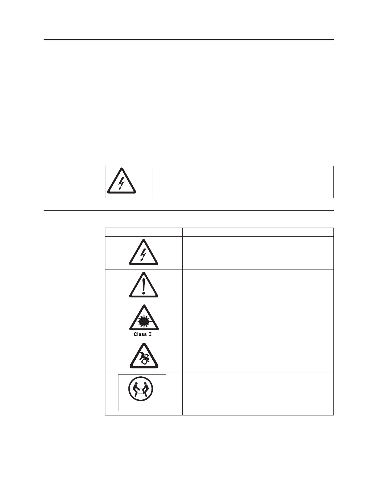
Caution Notices
If the symbol is... It means....
A hazardous electrical condition with less severity than
electrical danger.
A generally hazardous condition not represented by other
safety symbols.
A hazardous condition due to the use of a laser in the
product. Laser symbols are always accompanied by the
classification of the laser as defined by the U. S.
Department of Health and Human Services (for example,
Class I, Class II, and so forth).
A hazardous condition due to mechanical movement in or
around the product.
A hazardous condition due to the weight of the unit.
Weight symbols are accompanied by an approximation of
the product’s weight.
18-32 kg (39.7-70.5 lbs)
© Copyright IBM Corp. 2004, 2006 xi
svc00167
Page 14

Performing the Safety Inspection Procedure
Before you service the unit, perform the following safety inspection procedure:
1. Stop all activity on the SCSI bus.
2. Turn off the power to the tape drive.
3. Disconnect the SCSI cable and check the SCSI bus terminator for damage.
4. Unplug the tape drive’s power cord from the electrical outlet.
5. Check the tape drive’s power cord for damage, such as a pinched, cut, or
frayed cord.
6. Check the tape drive’s SCSI bus (signal) cable for damage.
7. Check the cover of the tape drive for sharp edges, damage, or alterations that
expose its internal parts.
8. Check the cover of the tape drive for proper fit. It should be in place and
secure.
9. Check the product label on the bottom of the tape drive to make sure that it
matches the voltage at your outlet.
Tape Drive AC Grounding Inspection
1. Power off the drive.
2. Disconnect all cables.
3. See Figure 1 which is provided for reference only. Disconnect the power cord
from its source.
4. Inspect the power cable for visible cracks, wear, or damage.
Figure 1. AC Grounding Diagram (50 Hz and 60 Hz)
1 AC Ground
2 Chassis Frame
3 AC Ground Terminated in Power Supply
xii IBM TotalStorage 3580 Ta pe Drive Setup, Operator, and Service Guide
Page 15
Product Recycling and Disposal
This unit must be recycled or discarded according to applicable local and national
regulations. IBM encourages owners of information technology (IT) equipment to
responsibly recycle their equipment when it is no longer needed. IBM offers a
variety of product return programs and services in several countries to assist
equipment owners in recycling their IT products. Information on IBM product
recycling offerings can be found on IBM’s Internet site at
http://www.ibm.com/ibm/environment/products/prp.shtml.
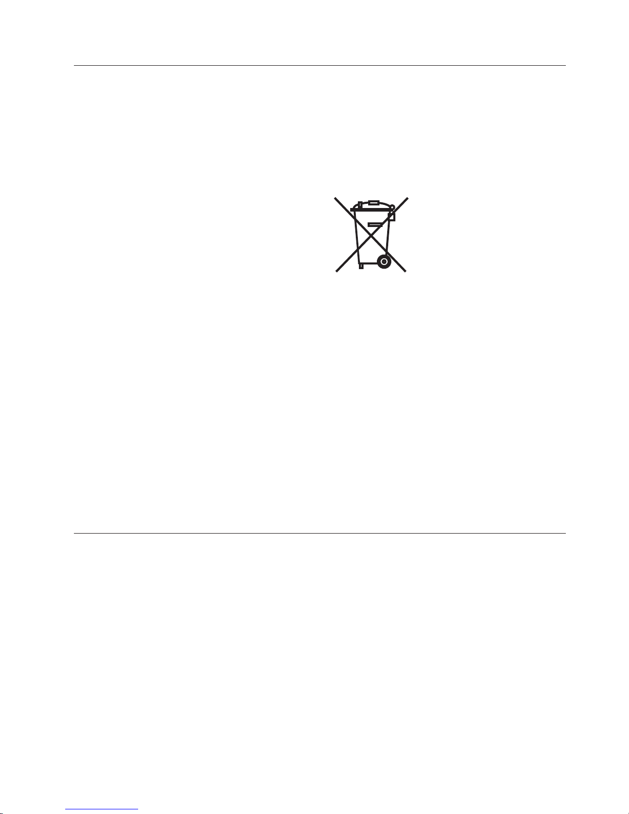
Notice: This mark applies only to countries within the European Union (EU) and
Norway.
Appliances are labeled in accordance with European Directive 2002/96/EC
concerning waste electrical and electronic equipment (WEEE). The Directive
determines the framework for the return and recycling of used appliances as
applicable throughout the European Union. This label is applied to various
products to indicate that the product is not to be thrown away, but rather
reclaimed upon end of life per this Directive.
In accordance with the European WEEE Directive, electrical and electronic
equipment (EEE) is to be collected separately and to be reused, recycled, or
recovered at end of life. Users of EEE with the WEEE marking per Annex IV of the
WEEE Directive, as shown above, must not dispose of end of life EEE as unsorted
municipal waste, but use the collection framework available to customers for the
return, recycling and recovery of WEEE. Customer participation is important to
minimize any potential effects of EEE on the environment and human health due
to the potential presence of hazardous substances in EEE. For proper collection and
treatment, contact your local IBM representative.
Battery Return Program
This product may contain sealed lead acid, nickel cadmium, nickel metal hydride,
lithium, or lithium ion battery. Consult your user manual or service manual for
specific battery information. The battery must be recycled or disposed of properly.
Recycling facilities may not be available in your area. For information on disposal
of batteries outside the United States, go to
http://www.ibm.com/ibm/environment/products/batteryrecycle.shtml or contact
your local waste disposal facility.
In the United States, IBM has established a return process for reuse, recycling, or
proper disposal of used IBM sealed lead acid, nickel cadmium, nickel metal
hydride, and other battery packs from IBM Equipment. For information on proper
disposal of these batteries, contact IBM at 1-800-426-4333. Please have the IBM part
number listed on the battery available prior to your call.
For Taiwan:
Safety and Environmental Notices xiii
Page 16

Please recycle batteries
Flat Panel Display
The fluorescent lamp or lamps in the liquid crystal display contain mercury.
Dispose of it as required by local ordinances and regulations.
End of Life (EOL) Plan
This box is a purchased unit. Therefore, it is the sole responsibility of the purchaser
to dispose of it in accordance with local laws and regulations at the time of
disposal.
This unit contains recyclable materials. The materials should be recycled where
facilities are available and according to local regulations. In some areas IBM may
provide a product take-back program that ensures proper handling of the product.
For more information, contact your IBM representative.
xiv IBM TotalStorage 3580 Ta pe Drive Setup, Operator, and Service Guide
Page 17

Preface
®
This guide describes how to install and use the IBM TotalStorage
3580 Tape Drive
in the following chapters:.
“Product Description” on page 1 describes the product, discusses supported
servers, operating systems, and device drivers, and lists hardware specifications.
“Installation” on page 7 gives unpacking, set up, and configuration information.
“Operation” on page 15 describes the Power Button, Unload Button, and Status
Light and explains the function of the Single-character Display. It gives instruction
on inserting and removing a tape cartridge, describes methods of updating drive
firmware, and explains how to clean the tape drive. It also lists diagnostic and
maintenance functions.
“Ultrium Media” on page 23 describes the types of tape cartridges to use and
defines the conditions for storing and shipping them. It also describes how to
handle the cartridges, how to set a cartridge’s write-protect switch, and how to
order additional cartridges.
“Troubleshooting” on page 45 gives tips for solving problems.
“Features, Replacement Parts, and Power Cords” on page 55 lists parts and
supplies and provides information about the power cords that are used in different
countries or regions.
Appendix A, “Error Codes,” on page 61 describes the error and informational
codes that appear on the single-character display.
Appendix B, “Performing Diagnostic and Maintenance Functions,” on page 67
describes the procedures that are used to identify and correct problems.
Appendix C, “TapeAlert Flags,” on page 83 lists TapeAlert messages that are
supported and that may aid during problem determination.
Appendix D, “Installing a 19-inch Rack Mount Kit,” on page 85 describes how to
install the Rack Mount Kit.
Appendix E, “Information for Authorized Service Personnel,” on page 89 gives the
procedure for removing a tape cartridge that will not eject from the drive.
© Copyright IBM Corp. 2004, 2006 xv
Page 18

Related Publications
Refer to the following publications for additional information. To ensure that you
have the latest publications, visit the web at http://www.ibm.com/storage/lto.
v IBM TotalStorage 3580 Tape Drive Quick Reference, GC26-7709, illustrates how to
configure and operate the IBM TotalStorage Ultrium Tape Drive (Generation 3).
v IBM TotalStorage LTO Ultrium Tape Drive SCSI Reference, GA32–0450, gives
information about the supported SCSI commands and protocol for the tape
drive.
v IBM Ultrium Device Drivers Installation and User’s Guide, GA32-0430, provides
instructions for attaching IBM-supported hardware to open-systems operating
systems. It indicates what devices and levels of operating systems are supported,
gives the requirements for adapter cards, and tells how to configure servers to
use the device driver with the Ultrium family of devices.
v IBM Ultrium Device Drivers Programming Reference, GC35-0483, supplies
information to application developers who want to integrate their open-systems
applications with IBM-supported Ultrium hardware. The reference contains
information about the application programming interfaces (APIs) for each of the
various supported operating-system environments. Yo u can obtain this reference
via File Transfer Protocol (FTP) at ftp://ftp.software.ibm.com/storage/devdrvr.
v IBM Translated Safety Notices, 96P0851, provides translation of danger and caution
notices.
xvi IBM TotalStorage 3580 Ta pe Drive Setup, Operator, and Service Guide
Page 19

Product Description
The IBM TotalStorage 3580 Tape Drive Model L33/L3H offers high-capacity,
performance, and technology designed for the midrange open systems
environment. This new model incorporates the new Linear Tape-Open (LTO) IBM
TotalStorage Ultrium Tape Drive (Generation 3), which more than doubles
maximum tape drive performance over the Generation 2 LTO Ultrium Tape Drive
(Ultrium 2). This tape drive comes with a SCSI Ultra160 LV D attachment, for
|
|
connection to a wide spectrum of open system servers. This tape drive is
compliant with Directive 2002/95/EC of the European Parliament.
a67ru003
Figure 2. The IBM TotalStorage 3580 Tape Drive
Features include:
v Native storage capacity of 400 GB per cartridge (800 GB at 2:1 compression)
|
|
|
v Supports Ultrium 3 Write Once, Read Many (WORM) media (for more
information on WORM media, see “WORM (Write Once, Read Many)” on page
25)
v Native data transfer rate of up to 80 MB per second
v Burst data transfer rate of 160 MB per second
v New dual stage 16 channel head activator for precision head alignment to help
support higher track density with improved data integrity and backwards
compatibility with previous LTO generations
v Graceful dynamic braking designed to maintain tension until the tape comes to
a complete stop, to help prevent stretching or breaking the tape, and loose tape
wraps
v Larger internal buffer (the size has been doubled over the Ultrium 2 to 128 MB)
v New independent tape loader and threader motors designed to help with
cartridge insertion in the tape drive.
v Highly integrated electronics using IBM engineered copper technology designed
to reduced the total number of components in the drive, lower chip
temperatures, and reduce power requirements, helping to provide for a more
© Copyright IBM Corp. 2004, 2006 1
Page 20
reliable drive. The Generation 3 drive electronics also incorporate on-the-fly
error correction of soft errors in the memory arrays in data and control paths.
tape drive is an external stand-alone or rack-mountable unit and is the entry
The
point for the family of IBM Ultrium tape products. It provides an excellent
migration path from digital linear tape (DLT or SDLT), 1/4-inch, 4mm, or 8mm
tape drives.
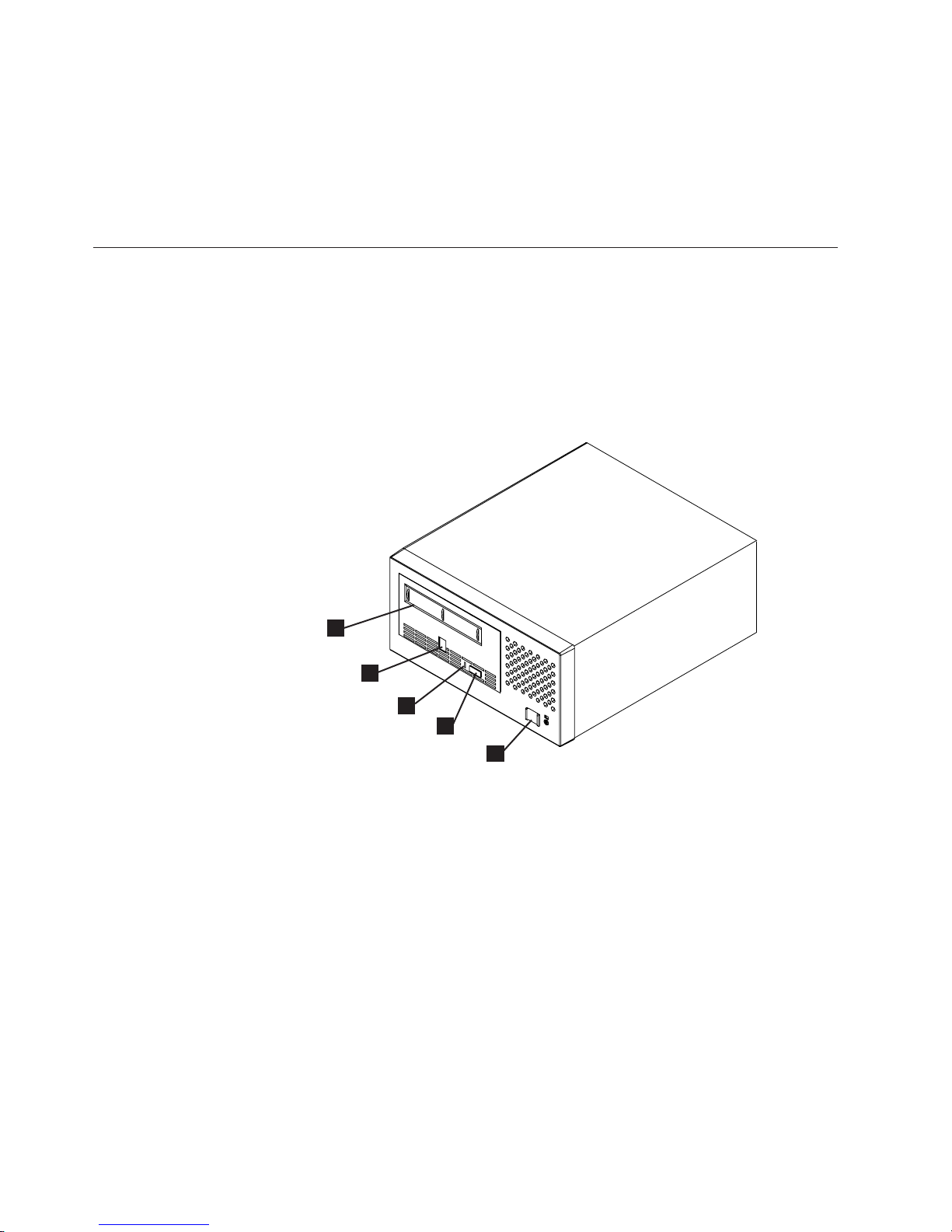
Front Panel Components
1 Cartridge load compartment 4 Unload Button (blue)
2 Single-character Display
(SCD)
5
Power Button (black)
3 Status Light
1
2
3
4
5
Figure 3. Front panel components
2 IBM TotalStorage 3580 Tape Drive Setup, Operator, and Service Guide
a67ru007
Page 21
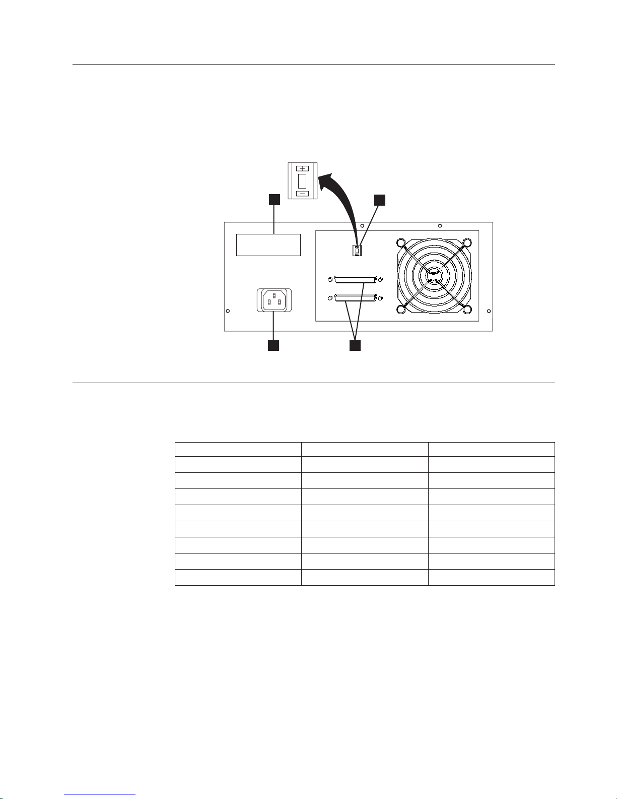
Rear Panel Components
1 Power receptacle 3 SCSI address switch
2 SCSI connectors 4 Serial number label
6
4
1
3
6
a67ru004
2
Figure 4. Rear panel components
3580 Models
Table 1 lists all 3580 models with associated SCSI attachment and drive type.
Table 1. 3580 Models
Model SCSI Attachment Tape Drive
L33 LV D Ultrium 3
L3H LV D Ultrium 3
L23 LV D Ultrium 2
H23 HVD Ultrium 2
L13 LV D Ultrium 1
L11 LVD Ultrium 1
H13 HVD Ultrium 1
H11 HVD Ultrium 1
Product Description 3
Page 22

Drive Performance
If you run applications that are highly dependent on tape-processing speed, take
advantage of the significant performance improvements provided by this tape
drive.
Table 2. Performance characteristics
Performance Characteristics Ultrium 3 Tape Drive
Native data rate 80 MB/s
(with Ultrium 3 media)
Maximum sustained data rate (at maximum compression) 135 MB/s (Ultra160)
Burst data rate for Low Voltage Differential (LVD) SCSI drives 160 MB/s (Ultra160)
Nominal load-to-ready time 15 seconds
Nominal unload time 15 seconds
Average search time to first byte of data 46 seconds
Maximum rewind time 88 seconds
Note: All sustained data rates are dependent on the capabilities of the interconnect (for example, an UltraSCSI bus
is limited to less than 40 MB/sec).
By using the built-in data-compression capability of the tape drive, greater data
rates than the native data transfer rate can be achieved. However, the actual
throughput is a function of many components, such as the host system processor,
disk data rate, block size, data compression ratio, SCSI bus capabilities, and system
or application software.
Supported Servers and Operating Systems
The 3580 attaches to many servers and many operating systems. To determine the
latest supported attachments, visit the web at http://www.ibm.com/storage/lto.
For specific instructions about attaching the 3580 , see “Configure the Tape Drive
to a Server/Host” on page 13.
4 IBM TotalStorage 3580 Tape Drive Setup, Operator, and Service Guide
Page 23

Supported Device Drivers
IBM offers device drivers which enable the tape drive to interact with a variety of
servers. To properly install an IBM device driver (if required), refer to the IBM
Ultrium Device Drivers Installation and User’s Guide. For applications that use other
device drivers, see the application’s documentation to determine which drivers to
use.
IBM maintains the latest levels of device drivers and driver documentation for the
Ultrium 3 tape products on the Internet. To access this material from your browser
or through the IBM FTP site, perform one of the following procedures. (Note: If
you do not have Internet access and you need information about device drivers,
contact your Marketing Representative.)
v Using a browser, type one of the following:
– http://www.ibm.com/storage/lto
– ftp://ftp.software.ibm.com/storage/devdrvr
– ftp://207.25.253.26/storage/devdrvr
v Using an IBM FTP site, enter the following specifications:
– FTP site: ftp.software.ibm.com
– IP Addr: 207.25.253.26
– Userid: anonymous
– Password: (use your current e-mail address)
– Directory: /storage/devdrvr
IBM
/storage/devdrvr/Doc directory:
v IBM_ultrium_tape_IUG.ps and IBM_ultrium_tape_IUG.pdf contain the current
version of the IBM Ultrium Device Drivers Installation and User’s Guide
v IBM_ultrium_tape_PROGREF.ps and IBM_ultrium_tape_PROGREF.pdf contain
the current version of the IBM Ultrium Device Drivers Programming Reference
Device
/storage/devdrvr/ in the following directories (the device driver for the iSeries
or AS/400
v AIX
v HPUX
v Linux
v Solaris
v Windows
TapeAlert Support
The tape drive is compatible with TapeAlert technology, which provides error and
diagnostic information to the server. For more information, see Appendix C,
“TapeAlert Flags,” on page 83.
provides PostScript- and PDF-formatted versions of its documentation in the
drivers and utilities for each supported server are beneath
®
server is included in the OS/400
®
®
®
®
operating system):
™
Product Description 5
Page 24

Specifications
The following are specifications for the tape drive. Specifications for tape cartridges
are given in “Environmental and Shipping Specifications for Tape Cartridges” on
page 40.
Table 3. Specifications
Physical Specifications
Specification Dimensions
Width 25.02 cm (9.85 in.)
Length 29.21 cm (11.5 in.)
Height 12.06 cm (4.75 in.)
Weight 6.45 kg (14.2 lbs.)
Power Specifications
AC line voltage 100 to 240 Vac
Line frequency 50 to 60 Hz, auto-ranging
Line current at 100
Va c
Line current at 240
Va c
1.0 A
0.5 A
Other Specifications
Maximum altitude 2500 m (8202 ft)
Environmental Specifications
Environmental
Factor
Temperature
Operating Storage Shipping
10 to 38°C
(50 to 100°F)
−40 to 60°C
(−40 to 140°F)
−40 to 60°C
(−40 to 140°F)
Relative humidity 20 to 80% 10 to 90% 10 to 90%
Maximum wet bulb
temperature
26°C
(79°F)
Non-condensing Non-condensing
6 IBM TotalStorage 3580 Tape Drive Setup, Operator, and Service Guide
Page 25

Installation
Attention
This is a customer setup unit. It is the customer’s responsibility to install this
product.
Installation Overview
Installation involves the following steps:
__ 1. “Unpack the Tape Drive” on page 8
__ 2. “Verify the Shipment” on page 8
__ 3. “Install the Rack Mount Kit (optional)” on page 8
__ 4. “Inspect the Power Cord and Outlet” on page 9
__ 5. “Set the SCSI ID” on page 9
__ 6. “Position the Tape Drive” on page 9
__ 7. “Connect Power” on page 10
__ 8. “Run Write Performance Test (Function Code F)” on page 10
__ 9. “Install the SCSI Host Adapter Card (if required)” on page 11
__ 10. “Connect the SCSI Bus Cable” on page 11
__ 11. “Install Device Drivers” on page 13
__ 12. “Configure the Tape Drive to a Server/Host” on page 13
__ 13. “Update Drive Firmware” on page 13
__ 14. “Register for My Support” on page 14
© Copyright IBM Corp. 2004, 2006 7
Page 26

Unpack the Tape Drive
Attention
If you return the unit for service, ship it in its original or equivalent packing
material, or the warranty may be invalidated.
__ 1. Inspect the unit for shipping damage. If there is damage, do not install the
__ 2. Locate the label on the rear panel of the unit with the machine type, model
Verify the Shipment
Ensure that the following items are included in the shipment:
__ 1. Power cord (For the appropriate cord for your country or region, see
__ 2. IBM TotalStorage LTO Ultrium 400 GB Data Cartridge
__ 3. IBM TotalStorage LTO Ultrium Cleaning Cartridge
__ 4. Single-connector SCSI wrap tool
__ 5. Device driver kit that includes:
6. A 2.5 m host-to-device SCSI bus (signal) cable
__
__ 7. A SCSI terminator
|
__ 8. Optional Rack Mount Kit
__ 9. The IBM TotalStorage 3580 Tape Drive Model L33/L3H Quick Reference,
__ 10. The IBM TotalStorage 3580 Tape Drive Model L33/L3H Setup, Operator, and
__ 11. The IBM Translated Safety Notices manual
unit. Report the damage immediately by contacting your place of purchase.
number, and serial number of the unit (see 4 in Figure 4 on page 3). Make
a note of these numbers and store them in an easily accessible place. Should
you need to contact Technical Support, you will be asked for these numbers.
“Power Cords” on page 56.)
v CD that contains the device drivers, the IBM Ultrium Device Drivers
Installation and User’s Guide, and the IBM Ultrium Device Drivers
Programming Reference
GC26-7709
Service Guide, GC26–7708 (this guide)
Install the Rack Mount Kit (optional)
Refer to Appendix D, “Installing a 19-inch Rack Mount Kit,” on page 85. If you did
not order the optional kit, proceed to “Inspect the Power Cord and Outlet” on
page 9.
If you ordered a 24-inch rack mount kit, refer to the installation instructions
included in the kit.
8 IBM TotalStorage 3580 Tape Drive Setup, Operator, and Service Guide
Page 27

Inspect the Power Cord and Outlet
__ 1. Inspect the power cord plug to ensure that it matches the power receptacle.
If it does not match, see “Power Cords” on page 56 to determine the
appropriate power cord.
__ 2. Ensure that all associated electrical outlets are properly grounded and that
the circuit breaker is turned on.
Set the SCSI ID
DANGER
An
electrical outlet that is not correctly wired could place
hazardous voltage on metal parts of the system or the devices that
attach to the system. It is the responsibility of the customer to
ensure that the outlet is correctly wired and grounded to prevent
an electrical shock. (D004)
The SCSI ID is a unique address that identifies the unit to the server. To set the
SCSI ID:
__ 1. Refer to the following notes and decide what ID to assign to the unit.
Notes:
a. The range of SCSI IDs is 0 through 15. The priority of SCSI IDs is:
6, 5, 4, 3, 2, 1, 0, 15, 14, 13, 12, 11, 10, 9, 8.
7,
b. Do not select an ID that is already in use by any device on the SCSI bus.
c. Do not select the SCSI ID of the SCSI host adapter card. The priority of
this ID is usually higher than any device on the SCSI bus. Generally, the
SCSI ID for the host adapter is set to 7.
__ 2. Locate the SCSI address switch on the rear panel (see 3 in Figure 4 on
page 3).
__ 3. With a small, pointed object (such as a ballpoint pen), press the + or − push
button until the ID that you want displays on the switch.
Attention
If the SCSI ID is changed after installation, cycle power (turn it off then on
again) to activate the new SCSI ID.
Position the Tape Drive
Position the unit so it is convenient to the server. The only restrictions are the
length of the power cord and the length of the SCSI cable. Recommended locations
are:
v Away from high-traffic areas, especially if the floor is carpeted.
v Out of printer or copy rooms to avoid toner and paper dust. Do not store paper
supplies next to any unit.
v Away from moving air, such as doorways, open windows, fans, and air
conditioners.
v Off the floor.
v In a horizontal position.
Installation 9
Page 28

Connect Power
v Where the tape cartridge can be easily inserted.
The unit should not be stacked. Do not place anything on top of the unit.
__ 1. Ensure that the unit is powered off.
__ 2. Plug the power cord into the rear panel (see 1 in Figure 4 on page 3), then
plug the other end into a grounded electrical outlet.
__ 3. Ensure that a terminator (or SCSI bus with termination) is connected to one
of the two SCSI connectors at the rear of the unit. The Power-On Self Test
(POST) may not complete without SCSI termination.
__ 4. Power-on the unit by pressing the Power Button. The POST runs, which
checks all hardware except the drive head. During the POST, the
Single-character Display (SCD) flashes several segmented characters. Each
segmented character represents a test performed during the POST. When the
POST finishes, the SCD momentarily lights all segmented characters and
then goes blank.
Run Write Performance Test (Function Code F)
Approximate Run Time = 5 minutes
Total Number of Loops = 10
Function Code
to tape.
The diagnostic loops ten times. Press the Unload Button to stop the diagnostic and
exit maintenance mode. Pressing the Unload Button once will abort the test at the
end of the current test loop. Pressing the Unload Button twice will abort the test
immediately.
Attention
|
For this test, insert only a customer-supplied scratch (blank) data cartridge or
a cartridge that may be overwritten. During the test, the drive overwrites the
data on the cartridge.
1. Place the drive in maintenance mode. For instructions, see “Entering
Maintenance Mode” on page 68.
2. Press the Unload Button once per second until
cycle past the desired code, press the Unload Button once per second until the
code reappears.)
3. Press and hold the Unload Button for three or more seconds, then release it to
select the function. The SCD changes to a flashing
|
4. Insert a customer-supplied scratch (blank) data cartridge that is not
write-protected (or the tape drive will exit maintenance mode). The SCD
changes to a flashing
F
performs tests to ensure that the drive can read from and write
F
. The tape drive runs the tests.
F
appears in the SCD. (If you
C
.
10 IBM TotalStorage 3580 Ta pe Drive Setup, Operator, and Service Guide
Page 29

Note: If you inserted an invalid or write-protected tape cartridge,
in the SCD. The tape drive unloads the cartridge and exits maintenance
mode.
v If no error is detected, the test will loop and begin again. To stop the loop,
press the Unload Button for one second and release. When the loop ends,
temporarily appears in the SCD. The drive rewinds and unloads the tape,
partially ejects the cartridge, then exits maintenance mode. The solid amber
Status Light turns off.
v If the number of written data sets is at least 6% less than the total number of
data sets expected, the Status Light flashes amber, the tape drive posts an
error code to the SCD. To determine the error, locate the code in Table 13 on
page 61. The tape drive unloads the cartridge and exits maintenance mode.
To clear the error, turn the power off, then on again.
Install the SCSI Host Adapter Card (if required)
If there are no other devices attached to your server, an LV D SCSI host adapter
card may need to be installed in the server. To install an adapter, refer to the
instructions that accompany it, as well as to the section about SCSI card
installation in your server’s documentation. For a list of supported adapters and
required interposers, visit the web at http://www.ibm.com/storage/lto.
7
appears
0
Although the LV D hardware in the tape drive is capable of operating in the
single-ended (SE) mode, SE operation is not recommended or supported.
Connect the SCSI Bus Cable
For maximum performance, the quantity of tape drives that can be attached to one
SCSI bus is limited, and is based on the type of bus that you have and the amount
of data compression achieved. Ultra SCSI buses have a bandwidth of 40 MB per
second; Ultra2 SCSI buses have a bandwidth of 80 MB per second; Ultra160 SCSI
buses have a bandwidth of 160 MB per second. The tape drive is capable of data
transfer rates of up to 80 MB per second with no compression. For maximum
performance, it is recommended that you attach only one tape drive to an Ultra
SCSI bus, an Ultra2 SCSI bus, or an Ultra160 SCSI bus.
The SCSI bus cable connects the tape drive to the server. You can connect the SCSI
bus cable (and the terminator) to either SCSI connector on the tape drive. To
connect the cable:
__ 1. Ensure that the tape drive is powered off and plugged into the electrical
outlet.
__ 2. If the server’s SCSI bus is in operation, stop all activity on the bus that you
are connecting to (for instructions about how to stop SCSI bus activity, see
your server’s documentation).
__ 3. Determine the maximum allowable length of your bus cable.
v For an LV D bus with a single device, do not use a total cabling length
that exceeds 25 m (82 ft).
v For an LV D bus with multiple devices, do not use a total cabling length
that exceeds 12 m (39 ft).
Installation 11
Page 30
Attention
v Do not mix LVD and HVD SCSI host adapters, tape drives, or
terminators on the same bus, as they could become damaged.
v Data transfer protocol timeouts for tape and disk drives are very
dissimilar. For that reason, it is strongly recommended that you
avoid running tape and disk drives on the same host adapter. A
configuration with tape and disk on a single host adapter gives a
slow and unreliable performance.
|
|
|
v When connecting the tape drive to a server, be sure to use the SCSI
terminator (Part #23R5841), not the SCSI wrap tool (Part #23R5840
with white "Wrap Tool" label), to terminate the SCSI bus.
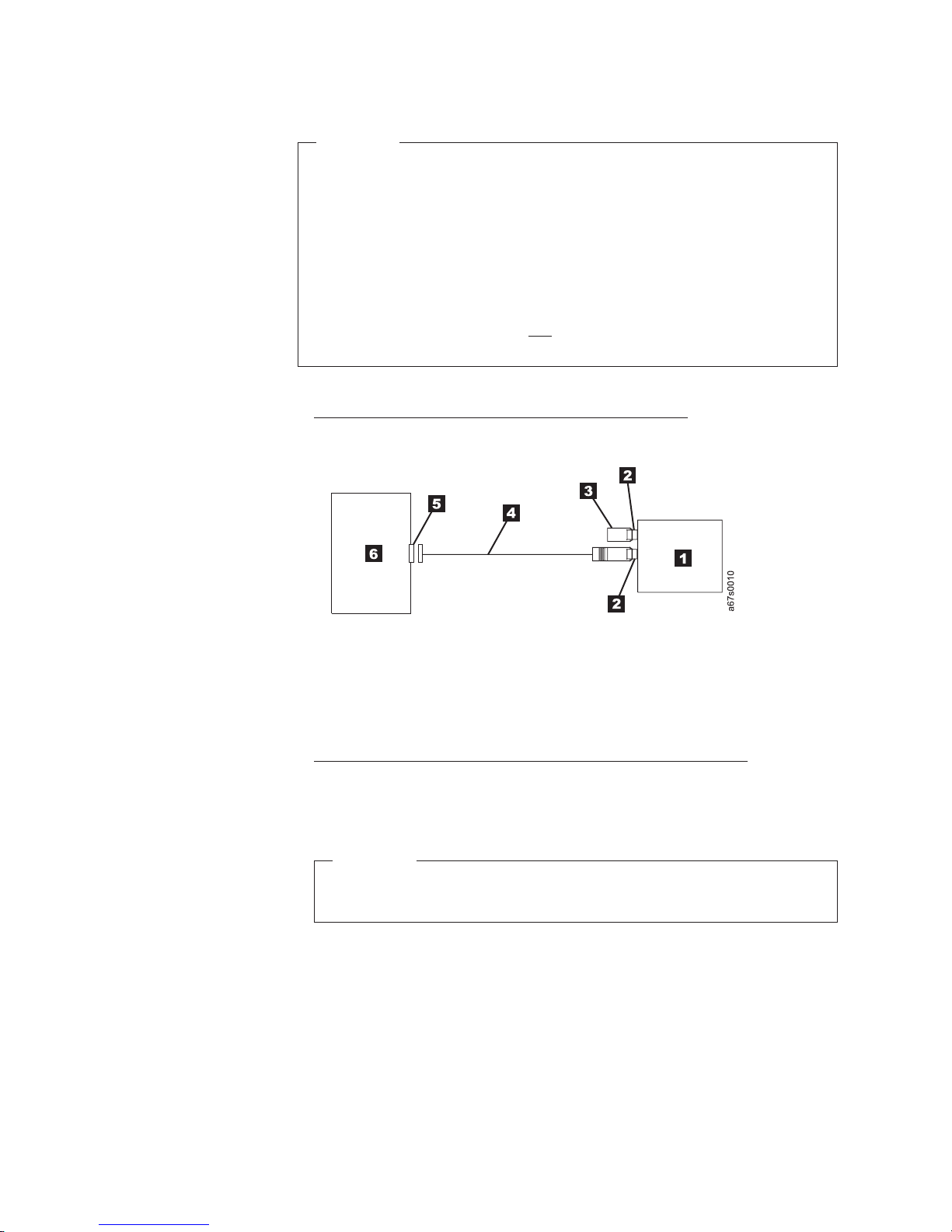
__ 4. Configure your tape drive similar to one of the following examples:
v If the tape drive is the only device on the SCSI Bus, connect the SCSI
bus cable to the server (see Figure 5).
Figure 5. Example of connecting one SCSI device to the server. The view is from the top.
1 Tape drive 4 SCSI bus cable
2 SCSI connectors 5 SCSI host adapter card
3 Terminator 6 Server
v If the tape drive is one of multiple devices on the SCSI Bus, connect the
SCSI bus cable to the next device on the bus, and move the terminator to
the last device on the bus (see Figure 6 on page 13). For a drive with an
LV D SCSI interface, use a cable with a total length of 12 m (39 ft) or less.
Attention
Do not mix LV D and HVD/DIFF SCSI host adapters, tape drives, or
terminators on the same bus, as they could become damaged.
12 IBM TotalStorage 3580 Ta pe Drive Setup, Operator, and Service Guide
Page 31

Figure 6. Example of connecting multiple SCSI devices to the server. The view is from the
top.
1 Tape drive 5 SCSI host adapter card
2 SCSI connectors 6 Server
3 Terminator 7 Another tape device
4 SCSI bus cable
Install Device Drivers
A device driver is firmware that enables the tape drive to interact with a variety of
servers. Refer to “Supported Device Drivers” on page 5 for instructions on
downloading the latest device drivers (the CD contains device drivers current at
time of manufacturing). Install device drivers as follows:
Note: If you intend to use the tape drive with a commercial software application,
it is recommended that you do not install any device driver from the CD
that was shipped with the tape drive, as conflicts could occur over which
driver controls the drive. Only install a device driver from the CD if the
instructions from your commercial software application tell you to do so.
v If you intend to use the tape drive with a commercial software application, refer
to that application’s installation instructions to install the device driver and
configure the tape drive.
v If you do not intend to use the tape drive with a commercial software
application, install the device driver from the CD that was shipped with the
drive. Refer to the installation instructions in the IBM Ultrium Device Drivers
Installation and User’s Guide, which is on the CD. The CD contains drivers and
installation instructions for supported operating systems.
Configure the Tape Drive to a Server/Host
__ 1. Power-on the unit.
__ 2. To configure the tape drive, refer to the documentation for your server/host
and application software.
Update Drive Firmware
As with all devices, it is recommended that you run the latest level of firmware
which can be downloaded by visiting http://www.ibm.com/storage/lto. Verify that
the latest level of firmware is installed on your machine before contacting IBM for
technical support (see “Procedure 1: Determining Firmware Level and Capturing
Drive Dump” on page 46). For information on updating drive firmware, see
“Updating Drive Firmware” on page 20.
Installation 13
Page 32

Register for My Support
My Support registration provides email notification when new firmware levels have
been updated and are available for download and installation. For more
information, see “Registering for My Support” on page iii.
14 IBM TotalStorage 3580 Ta pe Drive Setup, Operator, and Service Guide
Page 33

Operation
Operation of the tape drive involves the following front panel components:
v Power Button
v Unload Button
v Single-character Display (SCD)
v Status Light
components allow the user to:
These
v Insert and remove a tape cartridge
v Perform diagnostic and maintenance functions
v Update drive firmware
Power Button
Unload Button
The Power Button is a push button that turns the tape drive on or off. The button
is located on the front panel (see 5 in Figure 3 on page 2). When the Power
Button is in the off position, the primary electrical power within the enclosure is
still active. To remove all electrical power to the enclosure, unplug the power cord
from the receptacle at the rear of the drive (see 1 in Figure 4 on page 3).
When the unit is powered-on but idle, the Status Light (see 3 in Figure 3 on page
2) is solid green; when it is performing a function, the Status Light is flashing
green.
The Unload Button (4 in Figure 3 on page 2) enables the following functions to
be performed:
v Rewind the tape into the cartridge and eject the cartridge.
v Enter or exit maintenance mode, or perform diagnostic or maintenance
functions. For more information, see Appendix B, “Performing Diagnostic and
Maintenance Functions,” on page 67.
v A panic reset.
Attention
If you press the Unload Button during host operation, the tape drive ends the
command that is being processed, and unloads and ejects the tape cartridge.
Note that (depending on its location on the reel) the tape may take as long as
10 minutes to completely rewind and eject.
© Copyright IBM Corp. 2004, 2006 15
Page 34

Single-character Display (SCD)
The SCD (2 in Figure 3 on page 2) presents a single-character code for:
v Error conditions and informational messages
v Diagnostic or maintenance functions (while in maintenance mode only)
Appendix
informational messages. If multiple errors occur, the code with the highest priority
(represented by the lowest number) displays first. When the error is corrected, the
code with the next highest priority displays, and so on until no errors remain.
Appendix B, “Performing Diagnostic and Maintenance Functions,” on page 67 lists
the single-character codes that represent diagnostic or maintenance functions. To
initiate a function the unit must be in maintenance mode. The SCD is blank during
normal operation.
SCD Dot
While in maintenance mode, the drive may display a single red dot in the
lower-right corner of the single character display
dump is available for downloading.
The dot flashes if a dump is in flash memory. The dot turns off when a dump is
copied to the server/host, to a tape cartridge, or to flash memory (see “Function
Code 5: Copy Drive Dump” on page 73).
A, “Error Codes,” on page 61 lists the codes for error conditions and
8
. This indicates that a drive
Attention
If you power off the drive before downloading the dump, the dump will be
lost.
Status Light
The Status Light (3 in Figure 3 on page 2) provides information about the state
of the unit. The light can be green or amber, and (when lit) solid or flashing.
Table 4 on page 17 lists the conditions of the Status Light and Single-character
Display (SCD) and provides an explanation of what each condition means. For any
condition other than those listed, the Status Light is not illuminated.
16 IBM TotalStorage 3580 Ta pe Drive Setup, Operator, and Service Guide
Page 35

Table 4. Meaning of Status Light and Single-character Display (SCD)
If the
Status Light
is...
and the
SCD is...
Meaning
Off Off The drive has no power or is powered off.
Green Off The drive is powered on and in an idle state.
Flashing
Green
Flashing
Green
Off The drive is reading from the tape, writing to the tape, rewinding the tape, locating data
on the tape, loading the tape, or unloading the tape.
Off The drive contains a cartridge during the power-on cycle. In this case, the drive
completes POST and slowly rewinds the tape (the process may take up to 10 minutes).
The light stops blinking and becomes solid when the drive completes the recovery and is
ready for a read or write operation. To eject the cartridge, press the Unload Button.
Amber Displaying
Error Code
The drive is displaying error code(s) from the error code log on the SCD. For more
information, see “Function Code 9: Display Error Code Log” on page 75 and
Appendix A, “Error Codes,” on page 61.
Amber Red
The drive is powering on, resetting, or in maintenance mode.
numbers,
letters, or
segments
Amber Flashing
0
Amber Flashing
The drive is exiting from maintenance mode. For more information, see “Function Code
0: Exit Maintenance Mode” on page 68.
The drive is executing the selected function while in maintenance mode.
selected
function
Flashing
Amber once
per second
Flashing
Amber once
per second
Flashing
Amber
twice per
second
Displaying
error code
Displaying
C
Displaying
Function
Code
8
An error occurred and the drive or media may require service, or it may require cleaning.
Note the code on the SCD, then go to Table 13 on page 61 to determine the action that is
required.
The drive needs cleaning.
1
The drive is updating firmware.
The SCD will display a
8
if using an FMR cartridge.
The SCD will be off if using the SCSI interface. For more information, see “Updating
Drive Firmware” on page 20.
or Off
Flashing
Amber
Off The drive detected an error and is performing a firmware recovery. It will reset
automatically.
twice per
second
Flashing
Amber
twice per
Flashing
C
The drive is requesting a cartridge to be loaded.
second
Flashing
Off There is a drive dump in flash memory.
Amber
twice per
second
1
Power should not be removed from the drive until the microcode update is complete. The drive indicates that the
update is complete by resetting and performing POST.
Operation 17
Page 36

Inserting a Tape Cartridge
To insert a tape cartridge:
1. Power on the unit.
2. Ensure that the write-protect switch (1 in Figure 7) is set to the unlock
position (see “Write-Protect Switch” on page 28).
3. Grasp the cartridge so that the write-protect switch faces you.
4. Slide the cartridge into the tape load compartment (1 in Figure 3 on page 2)
until the cartridge loader draws the cartridge into the drive.
The Status Light will flash green, then become solid green. The Single-character
Display (SCD) will remain blank.
Notes:
a. If the cartridge is already in an ejected position and you want to reinsert it,
remove the cartridge then insert it again.
b. If the cartridge is already loaded and you cycle power (turn it off, then on),
the cartridge will reload.
c. If you set the write-protect switch so that data cannot be written to it (in the
locked position), the SCD will flash amber.
1
Figure 7. Inserting a cartridge
18 IBM TotalStorage 3580 Ta pe Drive Setup, Operator, and Service Guide
a67ru005
Page 37

Removing a Tape Cartridge
Attention
Failure to remove a cartridge before powering off the unit may result in
damage to the cartridge or to the drive.
To remove a cartridge:
1. Ensure that the unit is powered on.
Note: In the following step, the tape may take as long as 10 minutes to completely
rewind and eject (depending on its location on the reel).
Press the Unload Button. The Status Light will flash green while the tape
2.
rewinds. The drive then partially ejects the cartridge, and the Status Light will
turn off.
3. After the cartridge partially ejects, grasp the cartridge and remove it.
Mid-tape Recovery
If a power cycle or reset occurs while a cartridge is loaded, the drive will slowly
rewind the tape and eject the cartridge. The slow rewind may take up to 10
minutes.
Performing Diagnostic and Maintenance Functions
The tape drive can:
v Run drive diagnostics
v Update drive firmware from a field microcode replacement (FMR) tape
v Create an FMR tape
v Force a drive dump
v Copy a drive dump to tape
v Copy a drive dump to flash memory
v Erase flash memory
v Run a SCSI wrap test
v Convert an FMR tape to a blank tape
v Display the error code log
v Clear the error code log
v Test the tape cartridge and media
v Test the read/write function
v Test the drive head
To perform the preceding diagnostic and maintenance functions, place the drive in
|
maintenance mode. It is recommended that a customer-supplied scratch (blank)
data cartridge be used for diagnostic testing. For complete instructions about
performing each operation, see Appendix B, “Performing Diagnostic and
Maintenance Functions,” on page 67.
Operation 19
Page 38

Updating Drive Firmware
Attention:
v To ensure optimum performance, use the latest level of drive firmware. It is
the customer’s responsibility to obtain and install drive firmware.
v When updating firmware, do not power-off the drive until the update is
complete, or the firmware may be lost.
Periodically check for updated levels of drive firmware and the following
diagnostic tools by visiting the web at http://www.ibm.com/storage/lto. Update
drive firmware using:
v The ITDT tool
v The SCSI interface
v A field microcode replacement (FMR) tape cartridge
For instructions on obtaining a new firmware image or FMR tape, visit
http://www.ibm.com/storage/lto. To update the firmware, refer to the following
sections. To be notified by email of new levels of firmware available for
downloading, see “Registering for My Support” on page iii.
ITDT SCSI Firmware Update, Dump Retrieval, and
Library/Drive Test Tool
The ITDT tool offers multiple functional capabilities that simplify the task of
updating tape and library firmware. It is available for most major platforms
|
|
(Windows, AIX, Sun, Linux, and so on), and requires no special device drivers.
Note: The ITDT tool is available on the IBM website
http://www.ibm.com/storage/support/lto. In addition to the executable file
(.exe), a README file will be posted on the web page. The README file
describes the features and capabilities of the ITDT tool, provides
downloading instructions, and gives detailed information on how to use the
tool.
Yo u use the ITDT tool to perform the following tasks:
v Update firmware using SCSI to all IBM LT O Tape Drive and many Tape Library
products (non-IBM devices may not be selected).
v Upload drive and library dump files
v Perform drive and library diagnostics, including drive read/write diagnostics
ITDT tool is a command line utility. To invoke it, enter the executable itdt
The
from the directory where the tool is located. The Help feature gives a brief
explanation of each function and shows the required syntax.
Updating Firmware through the SCSI Interface
When updating drive firmware by using the SCSI interface, the procedure varies,
depending on whether your server uses an IBM tape device driver or a non-IBM
tape device driver (such as a driver from Sun, Hewlett-Packard, or Microsoft®).
20 IBM TotalStorage 3580 Ta pe Drive Setup, Operator, and Service Guide
Page 39

For instructions about updating firmware from a server that uses an IBM tape
device driver, refer to the IBM Ultrium Device Drivers Installation and User’s Guide.
To update firmware from a server that uses a non-IBM tape device driver, refer to
the documentation for that device.
Updating the Firmware with an FMR Tape Cartridge
Tip
After creating an FMR tape (see “Function Code 3: Create FMR Tape” on
page 71), the firmware of multiple drives can be updated with the same FMR
tape. After updating the drive firmware, unmake the FMR tape (see
“Function Code 8: Unmake FMR Tape” on page 75) and use it as a data
cartridge.
To update the drive’s firmware from an FMR tape cartridge:
1. Ensure that a cartridge is not loaded in the drive.
2. Place the drive in maintenance mode by pressing the Unload Button three
times within two seconds. The Status Light becomes solid amber, which means
that the drive is in maintenance mode.
3. Press the Unload Button once per second until
hold the button for three seconds. When
cartridge.
4. Insert the FMR tape cartridge.
firmware from the cartridge, and the Status Light flashes amber. When the
update completes successfully,
8
flashes, the drive loads the updated
0
displays and the cartridge automatically
ejects.
8
C
displays, then press and
flashes, the drive is waiting for a
drive resets itself and automatically activates the new firmware.
The
If the update fails, an error code displays. To resolve the error, locate the code in
Table 13 on page 61.
Cleaning the Drive Head
Attention
When cleaning the drive head, use the IBM TotalStorage LTO Ultrium
|
Cleaning Cartridge (part number 35L2086). Yo u may use another LT O
cleaning cartridge, but it may not meet the standards of reliability established
by IBM.
Clean the drive head whenever
the Status Light is flashing amber once per second. It is not recommended that you
clean the drive head on a periodic basis; only when the drive requests to be
cleaned.
C
displays on the Single-character Display and
Operation 21
Page 40

To clean the head, insert the cleaning cartridge into the tape load compartment (see
Figure 7 on page 18). The drive performs the cleaning automatically. The cleaning
cycle takes less than two minutes. When the cleaning is finished, the drive ejects
the cartridge.
|
Note: Anytime a cleaning cartridge is inserted, the drive detects the cleaning
|
|
|
|
|
The IBM TotalStorage LTO Ultrium Cleaning Cartridge is valid for 50 uses.
Cleaning the Tape Drive
Clean the exterior surface of the tape drive with a damp towel. If a liquid
all-purpose cleaner is used, apply it to the towel. Do not spray the enclosure.
cartridge and starts one cleaning cycle. After the cleaning cycle is finished,
the drive will eject the cartridge.
If an expired or defective cleaning cartridge is inserted, the drive will eject
this cartridge without cleaning the drive, and the cleaning bit will remain
on.
22 IBM TotalStorage 3580 Ta pe Drive Setup, Operator, and Service Guide
Page 41

Ultrium Media
To ensure that your IBM Ultrium Tape Drive conforms to IBM’s specifications for
reliability, use only IBM LTO Ultrium Tape Cartridges. You may use other
LTO-certified data cartridges, but they may not meet the standards of reliability
that are established by IBM. The IBM TotalStorage LTO Ultrium 400 GB Data
Cartridge cannot be interchanged with the media used in other IBM non-LTO
Ultrium tape products.
Figure 8 shows the IBM TotalStorage LTO Ultrium 400 GB Data Cartridge and its
components.
1 LTO cartridge memory 4 Write-protect switch
2 Cartridge door 5 Label area
3 Leader pin 6 Insertion guide
Figure 8. The IBM TotalStorage LT O Ultrium 400 GB Data Cartridge
Cartridge Compatibility
© Copyright IBM Corp. 2004, 2006 23
Table 5. Ultrium data and cleaning cartridge compatibility with Ultrium tape drive
IBM Ultrium Tape Drive
Ultrium 3 Read/Write Read/Write Read only
Ultrium 2 Read/Write Read/Write
Ultrium 1 Read/Write
IBM TotalStorage LTO Ultrium Data Cartridges
400 GB
(Ultrium 3)
200GB
(Ultrium 2)
(Ultrium 1)
100GB
Page 42

Data Cartridge
The different generations of IBM TotalStorage Ultrium data cartridges can be
identified by color:
Data Cartridge Case Color
Ultrium 3 Slate Blue
|
Ultrium 3 Write Once, Read Many (WORM) Slate Blue top; Grey bottom
Ultrium 2 Purple
Ultrium 1 Black
All three generations contain 1/2-inch, dual-coat, metal-particle tape. The native
data capacity of Ultrium data cartridges is as follows:
Data Cartridge Native Data Capacity
Ultrium 3 400 GB (800 GB at 2:1 compression)
Ultrium 2 200 GB (400 GB at 2:1 compression)
Ultrium 1 100 GB (200 GB at 2:1 compression)
When processing tape in the cartridges, Ultrium Tape Drives use a linear,
serpentine recording format.
v The Ultrium 3 drive reads and writes data on 704 tracks, 16 tracks at a time.
v The Ultrium 2 drive reads and writes data on 512 tracks, 8 tracks at a time.
v The Ultrium 1 drive reads and writes data on 384 tracks, 8 tracks at a time.
The first set of tracks (16 for Ultrium 3; 8 for Ultrium 2 and 1) is written from near
the beginning of the tape to near the end of the tape. The head then repositions to
the next set of tracks for the return pass. This process continues until all tracks are
written and the cartridge is full, or until all data is written.
The cartridge door (2 in Figure 8 on page 23) protects the tape from
contamination when the cartridge is out of the drive. Behind the door, the tape is
attached to a leader pin (3). When the cartridge is inserted into the drive, a
threading mechanism pulls the pin (and tape) out of the cartridge, across the drive
head, and onto a non-removable take-up reel. The head can then read or write data
from or to the tape.
The write-protect switch 4 prevents data from being written to the tape cartridge
(see “Write-Protect Switch” on page 28). The label area 5 provides a location to
place a label (see “Bar Code Label” on page 26). The insertion guide 6 is a large,
notched area that prevents the cartridge from being inserted incorrectly.
Yo u can order tape cartridges with bar code labels included, or you can order
custom labels. To obtain tape cartridges and bar code labels, see “Ordering Media
Supplies” on page 42.
All generations of the LTO Ultrium Data Cartridge have a nominal cartridge life of
5000 load and unload cycles.
24 IBM TotalStorage 3580 Ta pe Drive Setup, Operator, and Service Guide
Page 43

Capacity Scaling
To control the capacity of the cartridge (for example, to obtain a faster seek time)
issue the SCSI command SET CAPACITY. For information about this command,
refer to the IBM TotalStorage LTO Ultrium Tape Drive SCSI Reference.
|
WORM (Write Once, Read Many)
|
|
|
|
|
|
|
|
|
|
|
WORM Media
|
|
|
|
|
|
||
|
Certain records retention and data security applications require a Write Once, Read
Many (WORM) method for storing data on tape. To meet this data storage
requirement, a new WORM feature has been made available on IBM LTO Ultrium
generation 3 drives. The WORM feature can be enabled by upgrading to
WORM-capable drive firmware and using a special WORM tape cartridge (see
“WORM Media”).
No physical hardware changes are required to make Ultrium 3 drives compatible
with the WORM feature; however, appropriate WORM-capable drive firmware
must be installed. See “Requirements” on page 26 for minimum drive firmware
requirements.
Because standard read/write media are incompatible with the WORM feature, a
specially formatted WORM tape cartridge (see Figure 9) is required. Each WORM
cartridge has a unique, worldwide cartridge identifier (WWCID), which comprises
the unique CM chip serial number and the unique tape media serial number. See
“Ordering Media Supplies” on page 42 for information on how to choose and
purchase the appropriate WORM tape cartridges for your library.
|
|
Figure 9. Ultrium 3 WORM Tape Cartridge
|
|
|
|
|
|
|
|
|
|
|
|
Data Security on WORM Media
Certain built-in security measures help ensure that the data written on a WORM
cartridge does not become compromised, for example:
v The format of an IBM Ultrium 3 400 GB WORM Tape Cartridge is unlike that of
standard read/write media. This unique format prevents a drive that lacks
WORM-capable firmware from writing on a WORM tape cartridge.
v When the drive senses a WORM cartridge, the firmware prohibits the changing
or altering of user data already written on the tape. The firmware keeps track of
the last appendable point on the tape.
WORM Media Errors
The following conditions cause WORM media errors to occur:
a66ug050
Using Ultrium Media 25
Page 44

|
|
|
|
|
|
|
|
|
Requirements
|
|
|
|
|
|
|
|
Cleaning Cartridge
v Information in the servo manufacturer’s word (SMW) on the tape must match
information from the cartridge memory (CM) module in the cartridge. If it does
not match, a media Error Code 7 will post on the drive’s single-character display
(SCD).
v Inserting a WORM tape cartridge into a drive that is not compatible with
WORM causes the cartridge to be treated as an unsupported medium. The drive
will report a media Error Code 7. Upgrading the drive firmware to the correct
code level will resolve the problem.
To add WORM capability to your IBM LTO Ultrium generation 3 drive(s), you
need the following:
v IBM Ultrium 3 400 GB WORM tape cartridge(s) (see “Ordering Media Supplies”
on page 42)
v Firmware release 54xx or higher
Note: See “Updating Drive Firmware” on page 20 for instructions on upgrading
drive firmware.
With each drive, a universal IBM LTO Ultrium Cleaning Cartridge is supplied to
clean the drive heads. The drive itself determines when a head needs to be
cleaned. It alerts you by displaying
C
on the single-character display and the
status light flashing amber. To clean the head, insert the cleaning cartridge into the
tape load compartment (see Figure 7 on page 18). The drive performs the cleaning
automatically. When the cleaning is finished, the drive ejects the cartridge.
Bar Code Label
|
Note: If a cleaning cartridge is inserted when the drive does not need to be
cleaned or when the cartridge has expired, the drive will automatically eject
the cartridge. (The IBM Cleaning Cartridges are valid for 50 uses.)
To remove a cleaning cartridge, see “Removing a Tape Cartridge” on page 19.
A bar code label contains:
v A volume serial number (VOLSER) that is human-readable
v A bar code that a bar code reader can read
Table 6. Bar code label requirements for Ultrium tape drives and libraries
Ultrium Tape Drive/Library Bar Code Label Requirements
3580 Not required
3581 Required
3582 Required
3583 Required
TS3310 (3576) Required
3584 Required
26 IBM TotalStorage 3580 Ta pe Drive Setup, Operator, and Service Guide
Page 45

When read by a bar code reader, the bar code identifies the cartridge’s VOLSER to
the library. The bar code also identifies the cartridge is a data cartridge or cleaning
cartridge. In addition, the bar code includes the two-character media-type identifier
Lx, where x equals 1, 2, or 3. L identifies the cartridge as an LTO cartridge. 1
indicates that the cartridge is the first generation of its type; 2 indicates that the
cartridge is the second generation of its type; 3 indicates that the cartridge is the
third generation of its type. Figure 10 shows a sample bar code label for the LT O
Ultrium Tape Cartridge.
Tape cartridges can be ordered with the labels included or with custom labels. To
order tape cartridges and bar code labels, see “Ordering Media Supplies” on page
42. Bar code usage in IBM tape products must meet predefined specifications. They
include (but are not limited to):
v Eight uppercase alphanumeric characters, where the last two characters must be
L3, L2, or L1
v Label and printing to be non-glossy
v Nominal narrow line or space width of 0.423 mm (0.017 in.)
v Wide to narrow ratio of 2.75:1
v Minimum bar length of 11.1 mm (0.44 in.)
determine the complete specifications of the bar code and the bar code label,
To
visit the web at http://www.ibm.com/storage/lto, or contact your IBM Sales
Representative.
When attaching a bar code label to a tape cartridge, place the label only in the
recessed label area (see 5 in Figure 8 on page 23). A label that extends outside of
the recessed area can cause loading problems in the drive.
Attention
Do not place any type of mark on the white space at either end of the bar
code. A mark in this area may prevent a bar code reader from reading the
label.
TO123L3
L
Figure 10. Sample bar code label on the LTO Ultrium 3 Tape Cartridge. The volume serial
number (LTO123) and bar code are printed on the label.
Guidelines for Using Bar Code Labels
Apply the following guidelines whenever using bar code labels:
v Use only IBM-approved bar code labels on cartridges to be used in an IBM tape
product.
v Do not reuse a label or reapply a used label over an existing label.
a69i0082
Using Ultrium Media 27
Page 46

v Before applying a new label, remove the old label by slowly pulling it at a right
angle to the cartridge case.
v Use peel-clean labels that do not leave a residue after being removed. If there is
glue residue on the cartridge, remove it by gently rubbing it with your finger.
Do not use a sharp object, water, or a chemical to clean the label area.
v Examine the label before applying it to the cartridge. Do not use the label if it
has voids or smears in the printed characters or bar code (a library’s inventory
operation will take much longer if the bar code label is not readable).
v Remove the label from the label sheet carefully. Do not stretch the label or cause
the edges to curl.
v Position the label within the recessed label area (see 5 in Figure 8 on page 23).
v With light finger pressure, smooth the label so that no wrinkles or bubbles exist
on its surface.
v Verify that the label is smooth and parallel, and has no roll-up or roll-over. The
label must be flat to within 0.5 mm (0.02 in.) over the length of the label and
have no folds, missing pieces, or smudges.
v Do not place other machine-readable labels on other surfaces of the cartridge.
They may interfere with the ability of the drive to load the cartridge.
Write-Protect Switch
The position of the write-protect switch on the tape cartridge (see 1 in Figure 11
on page 29) determines whether you can write to the tape. If the switch is set to
the:
v The locked position
(solid red), data cannot be written to the tape.
v The unlocked position (black void), data can be written to the tape.
possible, use your server’s application software to write-protect your cartridges
If
(rather than manually setting the write-protect switch). This allows the server’s
software to identify a cartridge that no longer contains current data and is eligible
|
|
to become a customer-supplied scratch (blank) data cartridge. Do not write-protect
customer-supplied scratch (blank) cartridges; the tape drive will not be able to
write new data to them.
If you must manually set the write-protect switch, slide it left or right to the
desired position.
28 IBM TotalStorage 3580 Ta pe Drive Setup, Operator, and Service Guide
Page 47
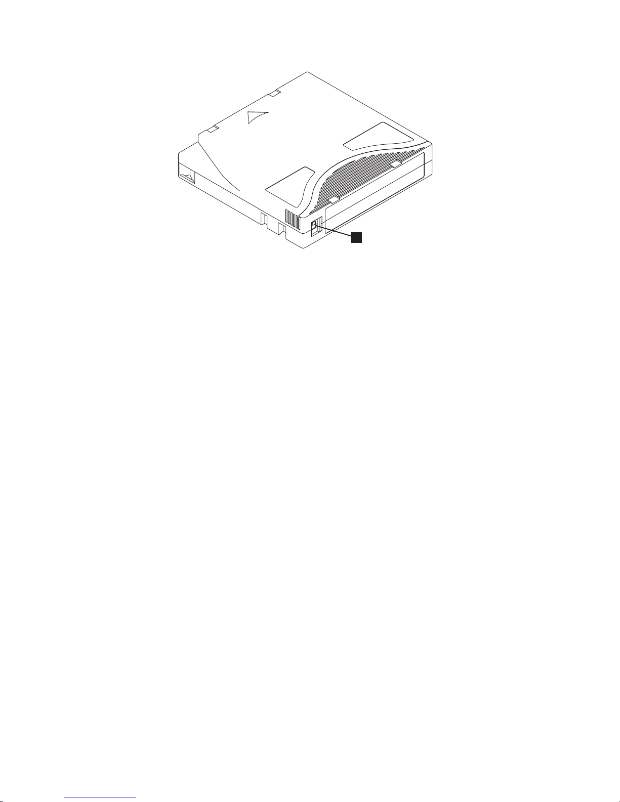
Figure 11. Setting the write-protect switch
1
A67E0026
Using Ultrium Media 29
Page 48

Handling the Cartridges
Attention
Do not use a damaged tape cartridge. A damaged cartridge can interfere with
the reliability of a drive and may void the warranties of the drive and the
cartridge. Before inserting a tape cartridge, inspect the cartridge case,
cartridge door, and write-protect switch for breaks.
Incorrect handling or an incorrect environment can damage cartridges or their
magnetic tape. To avoid damage to your tape cartridges and to ensure the
continued high reliability of your IBM LTO Ultrium Tape Drives, use the
guidelines described below.
Provide Training
v Post procedures that describe proper media handling in places where people
gather.
v Ensure that anyone who handles tape has been properly trained in handling and
shipping procedures. This includes operators, users, programmers, archival
services, and shipping personnel.
v Ensure that any service or contract personnel who perform archiving are
properly trained in media-handling procedures.
v Include media-handling procedures as part of any services contract.
v Define and make personnel aware of data recovery procedures.
Ensure Proper Packaging
v When shipping a cartridge, use the original or better packaging.
v Always ship or store a cartridge in a jewel case.
v Use only a recommended shipping container that securely holds the cartridge in
its jewel case during transportation. Ultrium Turtlecases (by Perm-A-Store) have
been tested and found to be satisfactory (see Figure 12 on page 31). They are
available at http://www.turtlecase.com.
30 IBM TotalStorage 3580 Ta pe Drive Setup, Operator, and Service Guide
Page 49

Figure 12. Tape cartridges in a Turtlecase
v Never ship a cartridge in a commercial shipping envelope. Always place it in a
box or package.
v If you ship the cartridge in a cardboard box or a box of a sturdy material, ensure
the following:
– Place the cartridge in polyethylene plastic wrap or bags to protect it from
dust, moisture, and other contaminants.
– Pack the cartridge snugly; do not allow it to move around.
– Double-box the cartridge (place it inside a box, then place that box inside the
shipping box) and add padding between the two boxes (see Figure 13).
Figure 13. Double-boxing tape cartridges for shipping
Provide Proper Acclimation and Environmental Conditions
v Before using a cartridge, let it acclimate to the normal operating environment for
1 hour. If condensation is visible on the cartridge, wait an additional hour.
v Ensure that all surfaces of a cartridge are dry before inserting it.
Using Ultrium Media 31
Page 50

v Do not expose the cartridge to moisture or direct sunlight.
v Do not expose recorded or blank cartridges to stray magnetic fields of greater
than 100 oersteds (for example, terminals, motors, video equipment, X-ray
equipment, or fields that exist near high-current cables or power supplies). Such
exposure can cause the loss of recorded data or make the blank cartridge
unusable.
v Maintain the conditions that are described in “Environmental and Shipping
Specifications for Tape Cartridges” on page 40.
Perform a Thorough Inspection
After purchasing a cartridge and before using it, perform the following steps:
v Inspect the cartridge’s packaging to determine potential rough handling.
v When inspecting a cartridge, open only the cartridge door. Do not open any
other part of the cartridge case. The upper and lower parts of the case are held
together with screws; separating them destroys the usefulness of the cartridge.
v Inspect the cartridge for damage before using or storing it.
v Inspect the rear of the cartridge (the part that loads first into the tape load
compartment) and ensure that there are no gaps in the seam of the cartridge
case (see 1 in Figure 14 and 4 in Figure 16 on page 35). If there are gaps in
the seam (see Figure 14), the leader pin may be dislodged. Go to “Repositioning
or Reattaching a Leader Pin” on page 34.
Figure 14. Checking for gaps in the seams of a cartridge
v Check that the leader pin is properly seated (see 2 in Figure 15 on page 34).
v If you suspect that the cartridge has been mishandled but it appears usable,
copy any data onto a good cartridge immediately for possible data recovery.
Discard the mishandled cartridge.
v Review handling and shipping procedures.
32 IBM TotalStorage 3580 Ta pe Drive Setup, Operator, and Service Guide
Page 51

Handle the Cartridge Carefully
v Do not drop the cartridge. If the cartridge drops, slide the cartridge door back
and ensure that the leader pin is properly seated in the pin-retaining spring clips
(see 2 in Figure 15 on page 34). If the leader pin has become dislodged, go to
“Repositioning or Reattaching a Leader Pin” on page 34.
v Do not handle tape that is outside the cartridge. Handling the tape can damage
the tape’s surface or edges, which may interfere with read or write reliability.
Pulling on tape that is outside the cartridge can damage the tape and the brake
mechanism in the cartridge.
v Do not stack more than six cartridges.
v Do not degauss a cartridge that you intend to reuse. Degaussing makes the tape
unusable.
Examples of Cartridge Problems
Example: Split Cartridge Case (see Figure 14 on page 32)
The cartridge’s case is damaged. There is a high possibility of media damage and
potential loss. Perform the following steps:
1. Look for cartridge mishandling.
2. Use the IBM Leader Pin Reattachment Kit (part number 08L9129) to correctly
seat the pin (see “Repositioning a Leader Pin” on page 34). Then, immediately
use data recovery procedures to minimize chances of data loss.
3. Review media-handling procedures.
Example: Improper Placement of Leader Pin (see Figure 15 on page 34)
The leader pin is misaligned. Perform the following steps:
1. Look for cartridge damage.
2. Use the IBM Leader Pin Reattachment Kit (part number 08L9129) to correctly
seat the pin (see “Repositioning a Leader Pin” on page 34). Then, immediately
use data recovery procedures to minimize chances of data loss.
Using Ultrium Media 33
Page 52

Repositioning or Reattaching a Leader Pin
Attention
Use a repaired tape cartridge only to recover data and move it to another
cartridge. Continued use of a repaired cartridge may void the warranties of
the drive and the cartridge.
If the leader pin in your cartridge becomes dislodged from its pin-retaining spring
clips or detaches from the tape, you must use the IBM Leader Pin Reattachment
Kit (part number 08L9129) to reposition or reattach it. (Do not reattach the pin if
you must remove more than 7 meters (23 feet) of leader tape.) The sections that
follow describe each procedure.
Repositioning a Leader Pin
A leader pin that is improperly seated inside a cartridge can interfere with the
operation of the drive. Figure 15 shows a leader pin in the incorrect 1 and correct
2 positions.
To place the leader pin in its proper position, you will need the following tools:
v Plastic or blunt-end tweezers
v Cartridge manual rewind tool (from Leader Pin Reattachment Kit, part number
08L9129)
Figure 15. Leader pin in the incorrect and correct positions. The cartridge door is open and
the leader pin is visible inside the cartridge.
34 IBM TotalStorage 3580 Ta pe Drive Setup, Operator, and Service Guide
Page 53

To reposition the leader pin, perform the following steps.
1. Slide open the cartridge door (1 in Figure 16) and locate the leader pin 2
(you may need to shake the cartridge gently to roll the pin toward the door).
2. With plastic or blunt-end tweezers, grasp the leader pin and position it in the
pin-retaining spring clips 3.
3. Press the leader pin gently into the clips until it snaps into place and is firmly
seated.
4. Close the cartridge door.
Figure 16. Placing the dislodged leader pin into the correct position. The cartridge door is
open to show the leader pin.
5. To rewind the tape, insert the cartridge manual rewind tool (1 in Figure 17)
into the cartridge’s hub 2 and turn it clockwise until the tape becomes taut.
Figure 17. Rewinding the tape into the cartridge
6. Remove the rewind tool by pulling it away from the cartridge.
7. If you suspect that the cartridge has been mishandled but it appears useable,
copy any data onto a good cartridge immediately for possible data recovery.
Discard the mishandled cartridge.
Using Ultrium Media 35
Page 54

Reattaching a Leader Pin
The first meter of tape in a cartridge is leader tape. Once the leader tape has been
removed there is a possibility of tape breakage. After reattaching the leader pin,
transfer data from the defective tape cartridge. Do not reuse the defective tape
cartridge.
The Leader Pin Reattachment Kit contains three parts:
v Leader pin attach tool (see 1 in Figure 18). A plastic brace that holds the
cartridge door open.
v Cartridge manual rewind tool (see 2 in Figure 18). A device that fits into the
cartridge’s hub and lets you wind the tape into and out of the cartridge.
v Pin supplies (see 3 in Figure 18). Leader pins and C-clips.
Attention
v Use only the IBM Leader Pin Reattachment Kit to reattach the leader pin to
the tape. Other methods of reattaching the pin will damage the tape, the
drive, or both.
v Use this procedure on your tape cartridge only when the leader pin
detaches from the magnetic tape and you must copy the cartridge’s data
onto another cartridge. Destroy the damaged cartridge after you copy the
data. This procedure may affect the performance of the leader pin during
threading and unloading operations.
v Touch only the end of the tape. Touching the tape in an area other than the
end can damage the tape’s surface or edges, which may interfere with read
or write reliability.
3
Figure 18. Leader Pin Reattachment Kit
1
2
A67E0042
36 IBM TotalStorage 3580 Ta pe Drive Setup, Operator, and Service Guide
Page 55

The following procedure describes how to reattach a leader pin.
To reattach a leader pin by using the IBM Leader Pin Reattachment Kit:
1. Attach the leader pin attach tool (1 in Figure 19) to the cartridge 2 so that
the tool’s hook 3 latches into the cartridge’s door 4. Pull the tool back to
hold the door open, then slide the tool onto the cartridge. Open the tool’s
pivot arm 5.
Figure 19. Attaching the leader pin attach tool to the cartridge. To hold the cartridge door
open, hook the tool into the door and pull the tool back.
Using Ultrium Media 37
Page 56

2. To find the end of the tape inside the cartridge, attach the cartridge manual
rewind tool (1 in Figure 20) to the cartridge’s hub 2 by fitting the tool’s
teeth between the teeth of the hub. Turn the tool clockwise until you see the
end of the tape inside the cartridge. Then, slowly turn the rewind tool
counterclockwise to bring the tape edge toward the cartridge door 3.
3. Continue to turn the rewind tool counterclockwise until approximately 13 cm
(5 in.) of tape hangs from the cartridge door. If necessary, grasp the tape and
pull gently to unwind it from the cartridge.
4. Remove the rewind tool by pulling it away from the cartridge. Set the tool
and the cartridge aside.
Figure 20. Winding the tape out of the cartridge. Turn the cartridge manual rewind tool
clockwise to see the end of the tape, then turn it counterclockwise to bring the tape to the
cartridge door.
5. On the leader pin (1 in Figure 21), locate the open side of the C-clip 2.
The C-clip is a small black part that secures the tape 3 to the pin.
6. Remove the C-clip from the leader pin by using your fingers to push the clip
away from the pin. Set the pin aside and discard the clip.
3
1
2
Figure 21. Removing the C-clip from the leader pin. Use your fingers to push the C-clip from
the leader pin.
A67E0036
38 IBM TotalStorage 3580 Ta pe Drive Setup, Operator, and Service Guide
Page 57

7. Position the tape in the alignment groove of the leader pin attach tool (see 1
in Figure 22).
8. Place a new C-clip into the retention groove 2 (Figure 22) on the leader pin
attachment tool and make sure that the clip’s open side faces up.
9. Place the leader pin (from step 6 on page 38) into the cavity 3 (Figure 22) of
the leader pin attach tool.
Attention
To prevent the leader pin from rolling into the cartridge, in the following
step use care when folding the tape over the pin.
10. Fold the tape over the leader pin and hold it with your fingers (see Figure 22).
Use care to ensure that the tape is centered over the leader pin. Failure
Note:
to properly center the tape on the pin will cause the repaired cartridge
to fail. When the tape is properly centered, a 0.25-mm (0.01-in.) gap
exists on both sides of the pin.
2
1
6
5
Figure 22. Attaching the leader pin to the tape
4
3
A67E0037
11. Close the pivot arm 4 of the leader pin attach tool by swinging it over the
leader pin so that the C-clip snaps onto the pin and the tape.
Using Ultrium Media 39
Page 58

12. Swing the pivot arm open and trim the excess tape 5 so that it is flush with
the reattached leader pin 6.
13. Use your fingers to remove the leader pin from the cavity 3 in the leader
pin attach tool.
14. Use the cartridge manual rewind tool to wind the tape back into the cartridge
(wind the tape clockwise). Ensure that the leader pin is latched by the
pin-retaining spring clips on each end of the leader pin.
15. Remove the rewind tool.
16. Remove the leader pin attach tool by lifting its end up and away from the
cartridge.
Attention
Use a repaired tape cartridge only to recover data and move it to another
cartridge. Continued use of a repaired cartridge may void the warranties of
the drive and the cartridge.
Environmental and Shipping Specifications for Tape Cartridges
Before you use a tape cartridge, acclimate it to the operating environment for 24
hours or the time necessary to prevent condensation in the drive (the time will
vary, depending on the environmental extremes to which the cartridge was
exposed).
The best storage container for the cartridges (until they are opened) is the original
shipping container. The plastic wrapping prevents dirt from accumulating on the
cartridges and partially protects them from humidity changes.
When you ship a cartridge, place it in its jewel case or in a sealed, moisture-proof
bag to protect it from moisture, contaminants, and physical damage. Ship the
cartridge in a shipping container that has enough packing material to cushion the
cartridge and prevent it from moving within the container.
Table 7 gives the environment for operating, storing, and shipping LTO Ultrium
Tape Cartridges.
Table 7. Environment for operating, storing, and shipping the LTO Ultrium Tape Cartridge
Environmental Specifications
1
Environmental Factor Operating Operational Storage
10 to 45°C
16 to 32°C
Temperature
Relative humidity
(noncondensing)
Maximum wet bulb
temperature
(50 to 113°F)
10 to 80% 20 to 80% 20 to 50% 5 to 80%
26°C
(79°F)
(61 to 90°F)
26°C
(79°F)
Archival Storage
16 to 25°C
(61 to 77°F)
26°C
(79°F)
2
Shipping
−23 to 49°C
(−9 to 120°F)
26°C
(79°F)
Notes:
1. Operational storage equals less than 1 year.
2. Archival storage equals 1 to 10 years.
40 IBM TotalStorage 3580 Ta pe Drive Setup, Operator, and Service Guide
Page 59

Disposing of Tape Cartridges
Under the current rules of the U.S. Environmental Protection Agency (EPA),
regulation 40CFR261, the LTO Ultrium Tape Cartridge is classified as
non-hazardous waste. As such, it may be disposed of in the same way as normal
office trash. These regulations are amended from time to time, and you should
review them at the time of disposal.
If your local, state, country (non-U.S.A.), or regional regulations are more
restrictive than EPA 40CFR261, you must review them before you dispose of a
cartridge. Contact your account representative for information about the materials
that are in the cartridge.
If a tape cartridge must be disposed of in a secure manner, you can erase the data
on the cartridge by using a high-energy ac degausser (use a minimum of 1200
oersted peak field over the entire space that the cartridge occupies). Degaussing
makes the cartridge unusable.
If you burn the cartridge and tape, ensure that the incineration complies with all
applicable regulations.
Using Ultrium Media 41
Page 60

Ordering Media Supplies
Table 8 lists the cartridges and media supplies that you can order for the tape
drive.
Table 8. Media Supplies
Supply Item Methods of Ordering
IBM TotalStorage LTO Ultrium 400 GB Data
Cartridge
Bar code labels are pre-applied to cartridges.
IBM TotalStorage LTO Ultrium 400 GB Data
Cartridge
Order VOLSER labels separately.
IBM Ultrium 3 400 GB WORM Tape
|
|
Cartridge (with label attached)
(3589 Model 028/Feature Code 2820 is a
20-pack of WORM cartridges labeled with
starting volume serial information and,
optionally, packed in individual jewel cases.)
IBM Ultrium 3 400 GB WORM Tape
|
Cartridge (without label attached)
|
(3589 Model 029/Feature Code 2920 is a
20-pack of WORM cartridges packed in
individual jewel cases with unattached blank
labels.)
IBM TotalStorage LTO Ultrium 200 GB Data
Cartridge
Bar code labels are pre-applied to cartridges.
IBM TotalStorage LTO Ultrium 200 GB Data
Cartridge
Order VOLSER labels separately (see
“Ordering Bar Code Labels” on page 43).
IBM LT O Ultrium 100 GB Data Cartridge
Order VOLSER labels separately (see
“Ordering Bar Code Labels” on page 43).
v Order the cartridge from your IBM Sales Representative or any
authorized IBM Business Partner by specifying Machine Type
3589 Model 009. Specify the VOLSER characters that you want.
v Order as part number 96P1470 (color label) or 96P1471 (black
and white label) through an IBM-authorized distributor (for the
closest distributor, visit the web at
http://www.ibm.com/storage/media). Or, call 1-888-IBM-MEDIA.
Specify the VOLSER characters that you want.
v Order the cartridge from your IBM Sales Representative or any
authorized IBM Business Partner by specifying Machine Type
3589 Model 008.
v Order as part number 24R1922 through an IBM-authorized
distributor (for the closest distributor, visit the web at
http://www.ibm.com/storage/media). Or, call 1-888-IBM-MEDIA.
Specify the VOLSER characters that you want.
v Order by Machine Type/Model and Feature Code through an
IBM-authorized distributor (for the closest distributor, visit the
web at http://www.ibm.com/storage/media).
v If you do not have Internet access, order the cartridge from any
authorized IBM Business Partner or your IBM Sales
Representative.
v Call 1-888-IBM-MEDIA.
v Order the cartridge from your IBM Sales Representative or any
authorized IBM Business Partner by specifying Machine Type
3589 Model 006. Specify VOLSER characters you want.
v call 1-888-IBM-MEDIA.
v Order the cartridge from your IBM Sales Representative or any
authorized IBM Business Partner by specifying Machine Type
3589 Model 007.
v call 1-888-IBM-MEDIA.
v Order as part number 08L9120 through an IBM-authorized
distributor (for the closest distributor, visit the web at
http://www.ibm.com/storage/media), or
v if you do not have Internet access, order the cartridge from any
authorized IBM Business Partner or your IBM Sales
Representative, or
v call 1-888-IBM-MEDIA.
42 IBM TotalStorage 3580 Ta pe Drive Setup, Operator, and Service Guide
Page 61

Table 8. Media Supplies (continued)
Supply Item Methods of Ordering
IBM TotalStorage LTO Ultrium Cleaning
Cartridge (universal cleaning cartridge for use
with Ultrium 1, Ultrium 2, and Ultrium 3
drives)
VOLSER labels are included.
v Order as part number 35L2086 through an IBM-authorized
distributor (for the closest distributor, visit the web at
http://www.ibm.com/storage/media), or
v if you do not have Internet access, order the cartridge from any
authorized IBM Business Partner or your IBM Sales
Representative, or
v call 1-888-IBM-MEDIA.
Leader Pin Reattachment Kit Order as part number 08L9129 through an IBM-authorized
distributor (for the closest distributor, visit the web at
http://www.ibm.com/storage/media).
Manual Rewind Tool Order as part number 08L9130 through an IBM-authorized
distributor (for the closest distributor, visit the web at
http://www.ibm.com/storage/media).
Ordering Bar Code Labels
The tape drive does not require cartridge bar code labels. However, if you use
your data cartridges or cleaning cartridges in an IBM tape library product, you
may need cartridge bar code labels if your tape library product requires them. Yo u
can order these labels separately from the IBM Data Cartridges and Cleaning
Cartridges.
Yo u can order bar code labels directly from the authorized label suppliers in
Table 9.
Table 9. Authorized suppliers of custom bar code labels
In America In Europe and Asia
EDP/Colorflex
2550 W. Midway Blvd.
Broomfield, CO 80020
U. S. A.
Telephone: 800-522-3528
http://www.colorflex.com/
Dataware
P. O . Box 740947
Houston, TX 77274
U. S. A.
Telephone: 800-426-4844
http://www.datawarelabels.com/
EDP Europe, Ltd.
43 Redhills Road
South Woodham Ferrers
Chelmsford, Essex CM3 5UL
U. K.
Telephone: 44 (0) 1245-322380
http://www.edpeurope.com/media_labelling.htm
Dataware Labels Europe
Heubergstrasse 9
D-83052 Bruckmuhl-Gotting
Germany
Telephone: 49 8062-9455
http://www.datawarelabels.com/
Using Ultrium Media 43
Page 62

Table 9. Authorized suppliers of custom bar code labels (continued)
In America In Europe and Asia
NetC
P. O. Box 1067
Fairfield, CT 06825
U. S. A.
Telephone: 203-372-6382
http://www.netcllc.com/
NetC Europe Ltd
To wn Farm Bungalow
The Pavement
North Curry
TA3 6LX
Somerset
U. K.
Telephone: 44 (0) 1823 49 1439
http://www.netclabels.co.uk
NetC Asia Pacific Pty Ltd
Locked Bag 1
Kenthurst
NSW 2156
Australia
Telephone: 61 (0) 2 4573 6556
http://www.netclabels.com.uk
44 IBM TotalStorage 3580 Ta pe Drive Setup, Operator, and Service Guide
Page 63

Troubleshooting
If you encounter problems when running the 3580, refer to the flowchart in
Figure 23. For explanations of codes on the Single-character Display (SCD), see
Appendix A, “Error Codes,” on page 61. Should the drive need to be replaced, go
to “Replacing the Tape Drive” on page 53. Please review the “Pre-Call Checklist”
on page 52 before calling IBM Technical Support.
Start
Does the
3580 Tape Drive
power on?
Yes
Does air flow
from the fan?
Yes
Does the
SCD and status
light indicate
an error?
No
Does the tape
cartridge load and
unload properly?
Yes
Does the
3580 Tape Drive
correctly
communicate
with the server?
Yes
1. If you are still having
problems running the 3580,
refer to the pre-call checklist
in this chapter before calling
IBM Technical Support.
2. Contact IBM Technical
Support.
No
No
Yes
No
No
1. Try another electrical outlet.
2. Try another power cord.
3. Refer to the pre-call checklist in this chapter before calling
IBM Technical Support.
4. Contact IBM Technical Support.
Refer to the pre-call checklist in this chapter before calling
IBM Technical Support. Contact IBM Technical Support.
1. Refer to the section about codes on the single-character
display in this guide.
2. Ensure that the latest level of firmware is installed on the
drive (refer to Procedure 1 in this chapter).
3. Refer to the pre-call checklist in this chapter before calling
IBM Technical Support.
4. Contact IBM Technical Support.
Refer to Procedure 2 in this chapter.
1. Ensure that the SCSI address switch is set to the correct
address (refer to Procedure 3 in this chapter).
2. Ensure that the pins in the SCSI cable and terminator
connectors are not damaged, and that the connectors are
properly seated (refer to Procedure 4 in this chapter).
3. Ensure that the SCSI communication path between the
host and the drive is functioning properly (refer to
Procedure 5 in this chapter).
a67ru001
Figure 23. Flowchart for analyzing maintenance problems
© Copyright IBM Corp. 2004, 2006 45
Page 64

Procedure 1: Determining Firmware Level and Capturing Drive Dump
Perform the following steps to determine the current firmware level installed on
the drive. The same utility can be used to update the firmware level as well as to
capture a drive dump which may be requested by technical support to aid in
problem analysis.
1. Use either the ITDT or LTO-TDX utilities (available on the web at
http://www.ibm.com/storage/lto) to view the current drive firmware level.
Compare this level with the latest available firmware level by visiting the same
website. For additional information about using the ITDT or LTO-TDX utilities,
see “Updating Drive Firmware” on page 20.
2. The same two utilities are excellent methods to either update drive firmware to
the latest level or to capture drive dumps from a drive which may be
experiencing problems. For additional information about using the ITDT or
LTO-TDX utilities, see “Updating Drive Firmware” on page 20.
Procedure 2: Inspecting a Cartridge for Damage
If the cartridge fails to load or unload properly, perform the following steps:
1. Check that the leader pin is attached and properly seated (see Figure 15 on
page 34) by opening the cartridge door and observing the pin’s placement.
2. Inspect the cartridge case, the cartridge door, and the write-protect switch for
damage.
3. Inspect the rear of the cartridge (the part that you load first into the tape load
compartment) and ensure that there are no gaps in the seam of the cartridge
case (see 1 in Figure 14 on page 32 and 4 in Figure 16 on page 35). If there
are gaps, the leader pin may be dislodged. Go to “Repositioning or Reattaching
a Leader Pin” on page 34.
4. Try loading or unloading another tape cartridge.
v If it fails, contact your service representative for additional problem
determination.
v If it is successful, discard the cartridge that originally failed.
Notes:
1. If a damaged or mishandled cartridge is the problem, see “Ultrium Media” on
page 23 for proper instructions about handling media. It is possible that your
other cartridges may also be damaged.
2. If your cartridge does not eject properly, contact your service representative.
(IBM service personnel should go to Appendix E, “Information for Authorized
Service Personnel,” on page 89.)
46 IBM TotalStorage 3580 Ta pe Drive Setup, Operator, and Service Guide
Page 65

Procedure 3: Verifying SCSI Address Switch Position
If your server is not communicating with the drive, the drive’s SCSI address switch
may be set incorrectly:
1. Check the SCSI address switch (3 in Figure 4 on page 3) to ensure that it is
set to the SCSI ID chosen in “Set the SCSI ID” on page 9.
2. Make sure that the ID is not one that is used by another device or the SCSI
host adapter (note that because ID 7 is the highest priority ID on the SCSI bus,
it is usually reserved for the primary SCSI host adapter).
3. If you change a SCSI ID, power cycle the drive to effect the change.
Procedure 4: Checking SCSI Connections
If your server is not communicating with the drive, the SCSI cable or terminator
connector pins may be damaged or not seated correctly, or the SCSI bus length
may be incorrect.
1. Check whether the SCSI ID is unique. If not, select a unique SCSI ID and
reconfigure the system. The new ID is effective at the next power-on.
2. Check whether the parameters for the SCSI adapter installation are correct.
3. Ensure that a SCSI terminator is attached to each end of the bus (one
terminator is usually installed at the server).
4. Ensure that no more than two bus terminations (typically, one on the host
adapter and one at the last device on the bus) are present.
5. Limit the number of devices on the bus.
6. Check that the SCSI connectors are properly seated (this includes the interposer
[if used], terminator, and cable connectors). Push the connectors into their
receptacle connectors, and (if applicable) tighten the retention screws until
firmly seated. Then, retry the operation.
7. If communication still fails, check all connector pins for damage. Remove the
interposer, terminator, and cable connectors, and inspect them for bent,
recessed, or missing pins. If necessary, replace the damaged component and
ensure that all connectors are properly seated, then retry the operation.
8. If communication still fails, check the length of the SCSI bus cable. If your
drive is the only device on the SCSI bus, ensure that the total bus length does
not exceed 25 m (82 ft). If there are other devices on the bus, ensure that the
total length does not exceed 12 m (39 ft).
9. If communication still fails, run the SCSI wrap test (see “Function Code 6: Run
SCSI Wrap Test” on page 74). If the test succeeds, the problem may be with the
cables or SCSI host adapter. Refer to your server’s documentation and exercise
a host utility to isolate the location of the problem. If the SCSI wrap test fails,
replace the terminator and run the test again.
Troubleshooting 47
Page 66

Procedure 5: Verifying SCSI Interface Communications
The SCSI Wrap Diagnostic tests SCSI function at the device interface. However, to
thoroughly verify host-to-device communications, it is highly recommended to
exercise activity over the SCSI bus from the host to the drive and back. A
recommended utility to perform this test is the ITDT utility available on the web at
http://www.ibm.com/storage/lto. This utility is especially effective for updating the
drive firmware and for performing the Test Device function. For additional
information about using the ITDT utility, see “Updating Drive Firmware” on page
20. Perform the following steps:
1. If the ITDT utility is not installed on your system, download the appropriate
operating system version from the web into a directory or folder of your choice
on your system.
2. When installation is complete, run the SCAN (s) option to determine if your
system can detect all of the Ultrium tape drive devices (including any libraries
or autoloaders that may be on the bus).
3. Select the drive that is to be tested or to have firmware downloaded.
4. For testing, select the Test Device (t) option.
This option will perform a series of LOADS, UNLOADS, and
Note:
WRITE/READ operations. Both SCSI control and data is sent to the
device over the SCSI bus.
5. If allowed to complete, the test will run for at least 30 minutes. At any time an
ABORT (a) can be entered to end the device test early if it is determined that
interface communications have been satisfactorily achieved.
Resolving Problems Reported by the Server
The procedure for fixing SCSI bus errors varies, depending on whether the error is
consistent or intermittent, and whether your configuration contains single or
multiple drives. The sections that follow describe how to fix each type of error.
Fixing SCSI Bus Errors
Note: If you are using a Storage Area Network (SAN) Data Gateway to convert a
drive with a SCSI interface to a Fibre Channel interface, ensure that the
problem is occurring between the SAN Data Gateway and the drive by
running the SCSI wrap test on the drive and running the SCSI loopback test
on the SAN Data Gateway. (To run the SCSI wrap test, see “Function Code
6: Run SCSI Wrap Test” on page 74; to run the SCSI loopback test, refer to
the section about that test in the IBM Storage Area Network Gateway Module
Setup, Operator, and Service Guide.)
Fixing a Consistent Error with a Single Drive on a SCSI Bus
1. Ensure that the power is on to the drive.
2. Ensure that the drive’s SCSI address is the same as the SCSI address assigned
by the server.
3. Run the SCSI wrap test (see “Function Code 6: Run SCSI Wrap Test” on page
74).
v If the test fails, replace the SCSI terminator first, then the SCSI cable and the
interposer (if installed). Repeat the operation that caused the error. If you
replaced the SCSI terminator or SCSI cable and the problem persists, the
48 IBM TotalStorage 3580 Ta pe Drive Setup, Operator, and Service Guide
Page 67

fault is with the server’s hardware or software. To isolate the cause of the
failure, refer to the server’s service documentation.
v If the test fails again, replace the drive (see “Replacing the Tape Drive” on
page 53).
v If the test is successful, refer to your enclosure documentation for additional
troubleshooting information.
Fixing a Consistent Error with Multiple Drives on a SCSI Bus
When a consistent error occurs in a configuration that has multiple drives on the
SCSI bus, you must determine if the problem exists with more than one drive. If
the problem is with all of the devices on the SCSI bus, the bus is stuck in a SCSI
phase and cannot change to another phase or the SCSI cable from the server to the
first device is defective.
1. Ensure that the SCSI cable from the server to the first device is connected.
2. Disconnect all but the first drive on the SCSI bus. Move the terminator to the
first SCSI device.
3. Run a device driver utility (such as IBM’s ntutil or tapeutil) to determine
whether the error will occur.
v If the error occurs, run the SCSI wrap test on the first drive (see “Function
Code 6: Run SCSI Wrap Test” on page 74).
– If the test runs successfully, replace the SCSI terminator first, then the
SCSI cable and the interposer (if installed) to the first drive. Repeat the
operation that caused the error. If you replaced the SCSI terminator or
SCSI cable and the problem persists, the fault is with the server’s
hardware or software. To isolate the cause of the failure, refer to the
server’s service documentation.
– If the test fails, replace the drive (see “Replacing the Tape Drive” on page
53).
If the error does not occur, connect one drive at a time back to the bus and
v
repeat step 3 for each drive until you can identify which drive is defective.
Ensure that the SCSI terminator is always on the last drive on the
Note:
SCSI bus.
Determine if the problem is with only one drive or with two or more drives.
4.
v If the problem is with only one drive, run the SCSI wrap test on that drive
(see “Function Code 6: Run SCSI Wrap Test” on page 74).
– If the test runs successfully, replace the SCSI terminator first, then the
SCSI cable to that drive and interposer (if installed).
– If the test fails, replace the drive (see “Replacing the Tape Drive” on page
53).
If the problem is with two or more drives, locate the first drive that has the
v
error and replace the SCSI cable that connects the drive and the interposer (if
installed).
Fixing an Intermittent Error with a Single Drive on a SCSI Bus
1. Replace the SCSI terminator on the drive.
2. Run the operation that caused the error. If the problem persists, the problem
may be with the cable.
3. Isolate which cable is causing the problem by replacing one cable at a time and
running the operation that caused the error after each replacement. If the
problem persists after all cables have been replaced, the problem may be with
the drive.
Troubleshooting 49
Page 68

4. Replace the drive (see “Replacing the Tape Drive” on page 53). If the problem
persists, the problem is with your server. Consult your server’s documentation.
Fixing an Intermittent Error with Multiple Drives on a SCSI Bus
Refer to the server’s error logs to determine which drive is the source of the
problem:
v If only one drive is reporting a SCSI failure, replace that drive (see “Replacing
the Tape Drive” on page 53).
v If multiple drives are reporting SCSI failures, the problem may be with the
terminator or the SCSI cables:
– Replace the terminator and run the operation that caused the error. If the
problem persists, the problem may be with the cables.
– Isolate which cable is causing the problem by replacing one cable at a time
and run the operation that caused the error after each replacement.
50 IBM TotalStorage 3580 Ta pe Drive Setup, Operator, and Service Guide
Page 69

Resolving Media-Related Problems
|
|
|
|
To resolve problems that are related to media, the drive’s firmware includes
diagnostics that verify whether a suspect cartridge and its magnetic tape are
acceptable for use. These diagnostics require the use of a customer-supplied scratch
(blank) data cartridge.
If you encounter a media-related problem, use the following procedure:
Attention
When you run the Test Cartridge & Media diagnostic, data on the suspect
|
tape is overwritten. Use only a customer-supplied scratch data cartridge to
run the test.
1. If possible, run the tape cartridge in a different drive. If the operation in the
other drive fails and
6
7
or
displays, replace the media. If the operation
succeeds, run the Test Cartridge & Media diagnostic (see “Function Code E:
Test Cartridge & Media” on page 77).
2. If the Test Cartridge & Media diagnostic fails, replace the media. If it runs
successfully, clean the drive and run the drive diagnostics (see “Cleaning the
Drive Head” on page 21 and “Function Code 1: Run Drive Diagnostics” on
page 69. If the drive diagnostics run successfully, perform the operation that
produced the initial media error.
Troubleshooting 51
Page 70

Pre-Call Checklist
If you have questions or problems, go through this checklist before contacting IBM
Technical Support. If your drive is the only device on the SCSI bus, ensure that the
total bus length does not exceed 25 m (82 ft). If there are other devices on the bus,
ensure that the total length does not exceed 12 m (39 ft.), perform the following
steps before you place a call to IBM Technical Support. Where instructions refer
you to the web, visit http://www.ibm.com/storage/lto.
__ 1. Perform a general checkup of the hardware and connections:
__ 2. Verify that the drive’s firmware is at the most recent level. To determine the
__ 3. Verify that your device drivers are at the most recent level:
__
__ 5. Review “Frequently Asked Questions and ″Hints and Tips” on the web.
__ 6. Run one of the following diagnostic methods:
v Verify that all cables (both ends) are connected properly.
v Ensure that you are using the correct SCSI terminator (LVD) and that you
are not mistakenly using a SCSI wrap plug (used for the diagnostic SCSI
wrap test).
v Before attaching the SCSI cables, ensure that the connector does not
contain bent or recessed pins.
v Ensure that all retention screws for the SCSI cable and terminator are
securely tightened.
latest release of firmware, visit the web. See “Updating Drive Firmware” on
page 20 for instructions on downloading the latest firmware.
v For IBM device drivers, visit the web.
v For the device drivers of independent software vendors (ISVs), visit the
appropriate third-party web site.
4. Verify whether your hardware and software configuration is supported. To
determine the latest supported attachments, visit the web.
v Local diagnostic:
a. Run “Function Code 1: Run Drive Diagnostics” on page 69 to
determine whether the drive can properly load and unload cartridges,
and read and write data. Optionally, you may run one of the following
diagnostics:
– “Function Code E: Test Cartridge & Media” on page 77 to
determine whether a suspect cartridge and its magnetic tape are
acceptable.
– “Function Code F: Write Performance Test” on page 78 to ensure
that the drive can read from and write to tape.
– “Function Code H: Test Head” on page 79 to ensure that the tape
drive’s head and tape-carriage mechanics work correctly.
– “Function Code J: Run Fast Read/Write Test” on page 80 to ensure
that the drive can read from and write to tape.
– “Function Code L: Load/Unload Test” on page 81 to test the drive’s
ability to load and unload a tape cartridge.
Run “Function Code 6: Run SCSI Wrap Test” on page 74.
b.
Remote diagnostic:
v
– Use the ITDT tool to run all tests listed in the local diagnostic section
that follows, as well as, to test the SCSI interface. For more
information, see “ITDT SCSI Firmware Update, Dump Retrieval, and
Library/Drive Test Tool” on page 20.
52 IBM TotalStorage 3580 Ta pe Drive Setup, Operator, and Service Guide
Page 71

Replacing the Tape Drive
To replace your tape drive, perform the following steps:
1. Remove the replacement unit from its packaging.
2. Locate the repair identification (RID) tag (included with the replacement unit).
See 1 in Figure 24)
3. Write down the serial number of the failed unit on the RID tag.
4. Affix the repair tag to the rear panel of the replacement unit (below the serial
number label).
5. Place the failed unit into the packaging of the replacement unit.
6. Follow the instructions (included with the replacement unit) for returning the
failed unit.
|
6
1
IBM REPAIR IDENTIFICATIONTAG
REPAIR IDTAG
MT
SN
PART NUMBER 19P5941
ATTENTION:
1.
A Repair ID tag maintains the original serial
number record of the machine and allows IBM
to entitle the machine for future maintenance
or warranty service. Mail in exchange requires
the completion and securing a Repair ID tag
(part number 19P5941) to the replacement
unit.
- Verify that the machine serial number on
the failing unit matches the serial number
reported to IBM technical support.
- Transcribe the machine type, model, and
serial number of the failing unit to the
Repair ID tag for the replacement unit.
USE BALLPOINT PEN TO
COMPLETE THE RIDTAG.
- Place the Repair ID tag as close as
possible, but not covering, the machine
serial number of the replacement unit.
- The original serial number must be visible.
The use of the Repair ID tag is important for
2.
customer inventory accuracy.
a67ru006
Figure 24. RID tag on rear panel
Troubleshooting 53
Page 72

54 IBM TotalStorage 3580 Ta pe Drive Setup, Operator, and Service Guide
Page 73

|
Features, Replacement Parts, and Power Cords
|
|
|
Optional Features
|
Table 10. Optional features for the 3580
Optional features, replacement parts, and power cords for your drive are listed in
this appendix along with associated feature code and part number.
Feature Code (FC) Product Description
1748 Custom QuickShip
5099 VHDCI/HD68 Cable/Interposer
5302 2.5 m HD68/HD68 SCSI Cable
5305 5 m HD68/HD68 SCSI Cable
5310 10 m HD68/HD68 SCSI Cable
5602 2.5 m VHDCI/HD68 SCSI Cable
5604 4.5 m VHDCI/HD68 SCSI Cable
5610 10 m VHDCI/HD68 SCSI Cable
8002 IBM TotalStorage Ultrium Cleaning Cartridge (Universal)
8301 IBM TotalStorage LTO Ultrium 400 GB Data Cartridge
7003 19-inch Rack Mount Kit
8724 24-inch Rack Mount Kit
Replacement Parts
|
Note: These part numbers are for use with libraries with serial numbers of 65000
or higher.
Table 11 . Replacement parts for the 3580
CRU Part Number Product Description
|
|
|
|
|
|
|
|
|
|
23R5919 3580 L33/L3H Replacement
23R3844 2.5 m HD68/HD68 SCSI Cable
23R3596 5 m HD68/HD68 SCSI Cable
23R3597 10 m HD68/HD68 SCSI Cable
23R3841 2.5 m VHDCI/HD68 SCSI Cable
23R3594 4.5 m VHDCI/HD68 SCSI Cable
23R3593 10 m VHDCI/HD68 SCSI Cable
23R5840 LVD SCSI wrap tool
23R5841 LVD terminator
35L2086 IBM TotalStorage Ultrium Cleaning Cartridge (Universal)
24R1922 IBM TotalStorage LTO Ultrium 400 GB Data Cartridge
© Copyright IBM Corp. 2004, 2006 55
Page 74

Power Cords
To avoid electrical shock, a power cord with a grounded attachment plug has been
provided. Use only properly grounded outlets.
Table 12. Power cords
Description, Feature Code
(FC), and Part Number
(PN)
US/Canada
v 2.8 m, 125V
v FC 9800
v PN 39M5081
Chicago
v 1.8 m, 125 V
v FC 9986
v PN 39M5080
Table 12 lists the power cord part number, feature code, the country or region
where the power cord can be used, and the plug’s standard reference. The last
column in the table contains an index number that you can match to a specific
receptacle type in “Types of Receptacles” on page 59.
All power cords use an appliance coupler that complies with the International
Electrotechnical Commission (IEC) Standard 320, Sheet C13.
If the power cord that you receive does not match your receptacle, contact your
local dealer.
Power cords used in the United States and Canada are listed by Underwriter’s
Laboratories (UL), are certified by the Canadian Standards Association (CSA), and
comply with the plug standards of the National Electrical Manufacturers
Association (NEMA). For other worldwide geographies, plug standards are listed
in Table 12.
Plug Standard Reference Country or Region
NEMA 5-15P Aruba, Bahamas, Barbados,
Bermuda, Bolivia, Brazil,
Canada, Cayman Islands,
Colombia, Costa Rica,
Curacao, Dominican
Republic, Ecuador, El
Salvador, Guatemala,
Guyana, Haiti, Honduras,
Jamaica, Japan, Liberia,
Mexico, Netherlands
Antilles, Nicaragua,
Panama, Peru, Philippines,
Saudi Arabia, South Korea,
Suriname, Taiwan, Trinidad
Tobago, Venezuela, US
NEMA 5-15P Chicago, U.S.A. 1
Index Number in Figure 25
on page 60
1
56 IBM TotalStorage 3580 Ta pe Drive Setup, Operator, and Service Guide
Page 75

Table 12. Power cords (continued)
Description, Feature Code
(FC), and Part Number
Plug Standard Reference Country or Region
(PN)
US/Canada
v 2.8 m, 250 V
v FC 9833
v PN 39M5095
Australia
v 2.8 m, 250V
v FC 9831
v PN 39M5102
France, Germany
v 2.8 m, 250V
v FC 9820
v PN 39M5123
Denmark
v 2.8 m, 250V
v FC 9821
v PN 39M5130
Index Number in Figure 25
NEMA 6-15P Aruba, Bahamas, Barbados,
Bermuda, Bolivia, Brazil,
Canada, Cayman Islands,
Costa Rica, Curacao,
Dominican Republic,
Ecuador, El Salvador,
Guatemala, Guyana, Haiti,
Honduras, Jamaica, Japan,
Liberia, Netherlands
Antilles, Nicaragua,
Panama, Peru, Philippines,
Suriname, Taiwan,
Thailand, Trinidad Tobago,
Venezuela, US
AS 3112
Argentina, Australia, China,
Colombia, New Zealand,
NZS 198
Papua New Guinea,
Paraguay, Uruguay,
Western Samoa
CEE 7 - VII Afghanistan, Algeria,
Andorra, Angola, Aruba,
Austria, Belgium, Benin,
Brazil, Bulgaria, Burkina
Faso, Burundi, Cameroon,
Central African Republic,
Chad, Congo-Brazzaville,
Curacao, Czech Republic,
Democractic Republic of
Congo, Denmark, Egypt,
Finland, France, French
Guiana, Germany, Greece,
Guinea, Hungary, Iceland,
Indonesia, Iran, Ivory
Coast, Jordan, Kenya,
Korea, Lebanon,
Luxembourg, Macau,
Malagasy, Mali, Martinique,
Mauritania, Mauritius,
Monaco, Morocco,
Mozambique, Netherlands,
Netherlands Antilles, New
Caledonia, Niger, Norway,
Poland, Portugal, Romania,
Russia, Saudi Arabia,
Senegal, Spain, Sweden,
Sudan, Syria, Togo, Tunisia,
Turkey, Yugoslavia, Zaire,
Zimbabwe, Vietnam
DK2-5A Denmark 5
on page 60
2
3
4
Parts Lists 57
Page 76

Table 12. Power cords (continued)
Description, Feature Code
(FC), and Part Number
Plug Standard Reference Country or Region
(PN)
South Africa
v 2.8 m, 250V
v FC 9829
v PN 39M5144
United Kingdom
v 2.8 m, 250V
v FC 9825
v PN 39M5151
Switzerland
v 2.8 m, 250V
v FC 9828
v PN 39M5158
Italy
v 2.8 m, 250V
v FC 9830
v PN 39M5165
Israel
v 2.8 m, 250V
v FC 9827
v PN 39M5172
Argentina
v 2.8 m, 250V
v FC 9834
v PN 39M5068
China
v 2.8 m, 250V
v FC 9840
v PN 39M5206
Taiwan LV *
v 2.8 m, 125V
v FC 9835
v PN 39M5247
Taiwan HV**
v 2.8 m, 250V
v FC 9841
v PN 39M5254
Index Number in Figure 25
on page 60
SABS 164 Bangladesh, Burma,
Pakistan, South Africa, Sri
Lanka
BS 1363 Antigua, Bahrain, Bermuda,
Brunei, Channel Islands,
China (Hong Kong S.A.R.),
Cyprus, Fiji, Ghana,
Guyana, India, Iraq,
Ireland, Jordan, Kenya,
Kuwait, Malaysia, Malawi,
Malta, Nepal, Nigeria,
Oman, Polynesia, Qatar,
Sierra Leone, Singapore,
Tanzania, Uganda, UK,
United Arab Emirate
(Dubai), Yemen, Zambia
SEV SN 416534 Liechtenstein, Switzerland 8
CEI 23- 16 Chile, Ethiopia, Italy, Libya,
Somalia
S11-32-1971 Israel 10
IEC 83-A5 Argentina, Brazil,
Colombia, Paraguay,
Trinidad Tobago, Uruguay
CCEE People’s Republic of China 12
CNS 10917-3 Taiwan 13
CNS 10917-3 Taiwan 14
6
7
9
11
58 IBM TotalStorage 3580 Ta pe Drive Setup, Operator, and Service Guide
Page 77

Table 12. Power cords (continued)
Description, Feature Code
(FC), and Part Number
Plug Standard Reference Country or Region
(PN)
Japan LV *
v 2.8 m, 125V
v FC 9842
v PN 39M5199
Japan HV**
v 2.8 m, 250V
v FC 9843
v PN 39M5186
Korea HV**
v 2.8 m, 250V
v FC 9844
v PN 39M5219
India HV**
v 2.8 m, 250V
v FC 9845
v PN 39M5226
Brazil LV *
v 2.8 m, 125V
v FC 9846
v PN 39M5233
Brazil HV**
v 2.8 m, 250V
v FC 9847
v PN 39M5240
* Low Voltage
Index Number in Figure 25
on page 60
JIS C8303, C8306 Japan 15
JIS C8303, C8306 Japan 16
KS C8305, K60884-1 Korea 17
IS 6538 India 18
InMetro NBR 6147 Brazil 19
InMetro NBR 14136 Brazil 20
** High Voltage
Types of Receptacles
Figure 25 on page 60 shows the plugs that are used by the power cords in Table 12
on page 56. Match the index number that is beside each plug to the index number
in the table.
Parts Lists 59
Page 78

123
4
56 7 8
9
13
10
14
11
15
12
16
17
18
Figure 25. Types of Receptacles
19
20
a77ug005
60 IBM TotalStorage 3580 Ta pe Drive Setup, Operator, and Service Guide
Page 79

Appendix A. Error Codes
Error codes are presented on the Single-character Display (SCD), and the Status
Light will be flashing amber once per second. If an error code displays, refer to
“Troubleshooting” on page 45 to determine the problem. Table 13 describes the
messages and codes.
Note: The codes on the SCD have different meanings, depending on whether they
display during normal operation or while the unit is in maintenance mode.
Codes that occur during normal operations are defined in Table 13. Codes
that occur while in maintenance mode are defined in Table 14 on page 67.
Table 13. Error codes on the Single-character Display. To clear error and cycle power, press the Unload Button for
ten seconds. A drive dump will be created.
Error Code Cause and Action
0
1
No error occurred and no action is required. This code displays:
v When power is cycled (turned off, then on) to the tape drive.
v When diagnostics have finished running and no error occurred.
The Single-character Display is blank during normal operation of the tape drive.
Note:
Cooling problem. The tape drive detected that the recommended operating temperature was
exceeded. Perform one or more of the following actions:
v Ensure that the cooling fan is rotating and is quiet. If not, replace the drive.
v Remove any blockage that prevents air from flowing freely through the tape drive.
v Ensure that the operating temperature and airflow is within the specified range (see
“Specifications” on page 6).
v If the operating temperature is within the specified range and the problem persists, replace the
drive.
The
8
error code clears when you power-off the tape drive or place it in maintenance mode.
Power problem. The tape drive detected that the externally supplied power is approaching the
specified voltage limits (the tape drive is still operating) or is outside the specified voltage limits
(the tape drive is not operating). Perform the following action:
1. Ensure that the power connector is properly seated.
2. Ensure that the proper dc voltages are being applied within the tolerances allowed (see
“Specifications” on page 6).
3. If the proper voltages are being applied but the problem persists, replace the unit.
The
error code clears when you power-off the tape drive or place it in maintenance mode.
© Copyright IBM Corp. 2004, 2006 61
Page 80

Table 13. Error codes on the Single-character Display (continued). To clear error and cycle power, press the Unload
Button for ten seconds. A drive dump will be created.
Error Code Cause and Action
3
Firmware problem. The tape drive determined that a firmware error occurred. Perform the
following action:
1. Collect a drive dump from one of the following:
Note: Do not force a new dump; the tape drive has already created one.
v Server’s SCSI interface by using a device driver utility or system tool (for instructions about
reading a drive dump from tape, visit the We b at http://www.ibm.com/storage/lto)
v Ultrium Tape Drive (to copy and read a drive dump, use “Function Code 5: Copy Drive
Dump” on page 73)
Power the tape drive off and on, then retry the operation that produced the error.
2.
3. If the problem persists, download new firmware and retry the operation.
4. If the problem persists, send the drive dump that you collected in step 1 to your IBM Support
Center.
The
8
error code clears when you power-off the tape drive or place it in maintenance mode.
Firmware or tape drive problem. The tape drive determined that a firmware or tape drive
hardware failure occurred. Perform the following action:
1. Collect a drive dump from one of the following:
Note: Do not force a new dump; one already exists.
v Server’s SCSI interface by using a device driver utility or system tool (for instructions about
reading a drive dump from tape, visit the We b at http://www.ibm.com/storage/lto)
v Ultrium Tape Drive (to copy and read a drive dump, use “Function Code 5: Copy Drive
Dump” on page 73)
Power the tape drive off and on, then retry the operation that produced the error. The error
2.
code clears when you power-off the tape drive or place it in maintenance mode.
3. If the problem persists, run “Function Code 1: Run Drive Diagnostics” on page 69.
v If the test FAILED, contact your IBM Support Center.
v If the test PASSED, ensure that you have installed the latest level of firmware, then contact
IBM Support Center and send the drive dump (that you collected in Step 1) to them.
5
Tape drive hardware problem. The drive determined that a tape path or read/write error
occurred. To prevent damage to the drive or tape, the tape drive will not allow you to insert a
cartridge if the current cartridge was successfully ejected. The error code may clear when you
cycle power to the tape drive or place it in maintenance mode. If the problem persists, replace the
drive.
Note: Copy the drive dump to flash memory before returning the drive. For instructions, refer to
“Function Code 5: Copy Drive Dump” on page 73.
62 IBM TotalStorage 3580 Ta pe Drive Setup, Operator, and Service Guide
Page 81

Table 13. Error codes on the Single-character Display (continued). To clear error and cycle power, press the Unload
Button for ten seconds. A drive dump will be created.
Error Code Cause and Action
6
Tape drive or media error. The tape drive determined that an error occurred, but it cannot isolate
the error to faulty hardware or to the tape cartridge. Perform the following action:
For Problems with Writing Data:
If the problem occurred while the tape drive was writing data to the tape, and if you know the
volume serial number (located on the cartridge label) of the tape cartridge that was loaded in the
drive when the problem occurred, retry the operation with a different cartridge:
v If the operation succeeds, the original cartridge was defective. Copy data from the defective
cartridge and discard it.
v If the operation fails and another tape drive is available, insert the cartridge into the other unit
and retry the operation.
– If the operation fails, discard the defective cartridge.
|
– If the operation succeeds, insert a customer-supplied scratch data cartridge into the first unit
and run “Function Code 1: Run Drive Diagnostics” on page 69.
- If the diagnostics fail, replace the tape drive.
- If the diagnostics succeed, the error was temporary.
v
|
If the operation fails and another tape drive is not available, insert a customer-supplied scratch
data cartridge into the unit and run “Function Code 1: Run Drive Diagnostics” on page 69.
– If the diagnostics fail, replace the tape drive.
– If the diagnostics succeed, discard the cartridge.
If
the problem occurs with multiple tape cartridges or if you do not know the tape cartridge’s
volume serial number, run “Function Code 1: Run Drive Diagnostics” on page 69:
v If the diagnostics fail, replace the tape drive.
v If the diagnostics succeed, run “Function Code H: Test Head” on page 79.
– If the diagnostic fails, replace the tape drive.
– If the diagnostic succeeds, replace the cartridges that caused the problem.
The
error code clears when you remove the tape cartridge or place the tape drive in maintenance
mode.
For Problems with Reading Data:
If the problem occurred while the tape drive was reading data from the tape, and if you know the
volume serial number of the tape cartridge, perform one of the following procedures:
v If another tape drive is available, insert the cartridge into the other unit and retry the operation:
– If the operation fails, discard the defective cartridge.
|
– If the operation succeeds, insert a customer-supplied scratch data cartridge into the first unit
and run “Function Code 1: Run Drive Diagnostics” on page 69:
- If the diagnostic fails, replace the tape drive.
- If the diagnostic succeeds, the error was temporary.
v
|
If another tape drive is not available, insert a customer-supplied scratch data cartridge into the
unit and run “Function Code 1: Run Drive Diagnostics” on page 69:
– If the diagnostic fails, replace the tape drive.
– If the diagnostic succeeds, discard the cartridge.
If the problem occurs with multiple tape cartridges or if you do not know the tape cartridge’s
volume serial number, run “Function Code 1: Run Drive Diagnostics” on page 69:
v If the diagnostic fails, replace the tape drive.
v If the diagnostic succeeds, run “Function Code H: Test Head” on page 79.
– If the diagnostic fails, replace the tape drive.
– If the diagnostic succeeds, replace the cartridges that caused the problem.
The
error code clears when you remove the tape cartridge or place the tape drive in maintenance
mode.
Appendix A. Error Codes 63
Page 82

Table 13. Error codes on the Single-character Display (continued). To clear error and cycle power, press the Unload
Button for ten seconds. A drive dump will be created.
Error Code Cause and Action
7
A high probability of media error. The tape drive determined that an error occurred because of a
faulty tape cartridge. Tr y another tape cartridge. If the problem occurs with multiple tape
cartridges, use the following procedure:
Attention:
|
overwritten. Use only a customer-supplied scratch data cartridge to run the test.
1. If possible, run the tape cartridge in a different tape drive. If the operation in the other unit
When you run the Test Cartridge & Media diagnostic, data on the suspect tape is
fails and
6
or
7
displays, replace the media. If the operation succeeds, run “Function
Code E: Test Cartridge & Media” on page 77.
v If the diagnostic fails, replace the media.
v If the diagnostic succeeds, clean the drive head (see “Cleaning the Drive Head” on page 21)
and run “Function Code 1: Run Drive Diagnostics” on page 69.
– If the drive diagnostic fails, replace the drive.
– If the drive diagnostic succeeds, perform the operation that produced the initial media
error.
The
error code clears when you remove the tape cartridge or place the tape drive in maintenance
mode.
8
Tape drive or SCSI bus failure. The tape drive determined that a failure occurred in the tape
drive’s hardware or in the SCSI bus. See “Procedure 4: Checking SCSI Connections” on page 47.
The error code clears 10 seconds after the drive detected the error or when you place the drive in
maintenance mode.
9
Tape drive or RS-422 error. The tape drive determined that a failure occurred in the tape drive’s
hardware or in the RS-422 connection. Replace the tape drive. The error code clears 10 seconds
after the drive detected the error or when you place the tape drive in maintenance mode.
64 IBM TotalStorage 3580 Ta pe Drive Setup, Operator, and Service Guide
Page 83

Table 13. Error codes on the Single-character Display (continued). To clear error and cycle power, press the Unload
Button for ten seconds. A drive dump will be created.
Error Code Cause and Action
A
Tape drive hardware problem. The tape drive determined that a problem occurred which
degraded the operation of the tape drive, but it did not restrict continued use. If the problem
persists, determine whether the problem is with the drive or the media.
Note: The drive is usable, though the Single-character Display continues to indicate an error and
the Status Light flashes amber. The error code may clear when you cycle power to the tape drive
or place it in maintenance mode.
To determine if the problem is with the drive hardware, or the tape media, perform the following
procedures:
1. If possible, run the tape cartridge in a different drive. If the operation in the other drive fails
and
6
or
7
displays, replace the media. If the operation succeeds, run the Test Cartridge
& Media diagnostic (see “Function Code E: Test Cartridge & Media” on page 77).
2. If the Test Cartridge & Media diagnostic fails, replace the media. If it runs successfully, clean
the failing drive and run the drive diagnostics (see “Cleaning the Drive Head” on page 21 and
“Function Code 1: Run Drive Diagnostics” on page 69). If the drive diagnostics run
successfully, perform the operation that produced the initial drive error.
3. If the problem persists replace the drive.
If
it is not possible to run the tape cartridge in a different drive, perform the following
procedures:
1. Clean the failing drive and run the drive diagnostics (see “Cleaning the Drive Head” on page
21 and “Function Code 1: Run Drive Diagnostics” on page 69). If the drive diagnostics run
successfully, run the Test Cartridge & Media diagnostic (see “Function Code E: Test Cartridge
& Media” on page 77).
2. If the Test Cartridge & Media diagnostic fails, replace the media. If it runs successfully,
perform the operation that produced the initial drive error.
3. If the problem persists replace the drive.
b
C
No error or message is assigned. See error code
The tape drive needs to be cleaned. Clean the tape drive. See “Cleaning the Drive Head” on page
21.
8
in this table.
The error code clears when you clean the tape drive or place it in maintenance mode.
d
|
No error or message assigned. See error code
The Unload Button was pushed in and did not release. Verify that the button pushes freely.
0
in this table.
Appendix A. Error Codes 65
Page 84

66 IBM TotalStorage 3580 Ta pe Drive Setup, Operator, and Service Guide
Page 85

Appendix B. Performing Diagnostic and Maintenance
Functions
Table 14 describes each diagnostic and maintenance function that the drive can
perform, gives the function code which appears on the Single-character Display
(SCD), and directs you to the instructions for performing the function. It is
|
Table 14. Diagnostic and maintenance functions
Function
Code
0
1
8
|
|
|
3
8
5
6
7
8
|
9
A
C
E
F
H
Exit Maintenance Mode: Causes the drive to become available for reading
and writing data.
Run Drive Diagnostics: Runs tests to determine whether the drive can
properly load and unload cartridges, and read and write data.
Update Tape Drive Firmware from FMR Tape:Loads updated firmware
from a field microcode replacement (FMR) tape.
Create FMR Tape: Copies its field microcode replacement (FMR) data to a
customer-supplied scratch (blank) data cartridge.
Force a Drive Dump: Performs a dump of data (also known as saving a
microcode trace).
Copy Drive Dump: Copies data from a drive dump (captured by using
Function Code 4) to the beginning of a customer-supplied scratch (blank)
data cartridge, copies a drive dump to flash memory, or erases a dump
from flash memory.
Run SCSI Wrap Test: Performs a check of the SCSI circuitry from and to
the SCSI connector.
Not available. Not available
Unmake FMR Tape: Erases the FMR data on a customer-supplied scratch
(blank) data cartridge and rewrite the cartridge memory on the tape. This
turns the cartridge into a valid customer-supplied scratch data cartridge.
Display Error Code Log: Displays the last 10 error codes, one at a time
(the codes are ordered; the most recent is presented first and the oldest
(tenth) is presented last).
Clear Error Code Log: Erases the contents of the error code log. Page 76
Insert Cartridge into Tape Drive: This function cannot be selected by
itself, but is a part of other maintenance functions (such as Run Tape
Drive Diagnostics and Create FMR Tape) that require a tape cartridge to
be loaded.
Test Cartridge & Media: Performs tests to ensure that a suspect cartridge
and its magnetic tape are acceptable.
Write Performance Test: Performs tests to ensure that the drive can read
from and write to tape.
Test Head: Performs tests to ensure that the tape drive’s head and
tape-carriage mechanics are working correctly.
recommended that you use a customer-supplied scratch (blank) data cartridge for
diagnostic testing.
Diagnostic or Maintenance Function
Instructions
Location
Page 68
Page 69
Page 70
Page 71
Page 72
Page 73
Page 74
Page 75
Page 75
Page 76
Page 77
Page 78
Page 79
© Copyright IBM Corp. 2004, 2006 67
Page 86

Table 14. Diagnostic and maintenance functions (continued)
Function
Code
J
L
P
U
Fast Read/Write Test: Performs tests to ensure that the drive can read
from and write to tape.
Load/Unload Test: Tests the drive’s ability to load and unload a tape
cartridge.
Enable Post Error Reporting: When selected, deferred-check conditions
are reported to the host.
Disable Post Error Reporting: When selected, deferred-check conditions
are NOT reported to the host.
Diagnostic or Maintenance Function
Entering Maintenance Mode
The drive must be in maintenance mode to run drive diagnostics or maintenance
functions. To place the unit in maintenance mode:
1. Make sure that no cartridge is in the drive.
2. Press the Unload Button three times within two seconds.
Single-character Display (SCD), and the Status Light turns amber.
Instructions
Location
Page 80
Page 81
Page 82
Page 82
0
appears in the
If a cartridge is in the tape drive, it will eject the first time that you press
Note:
the Unload Button and the drive will not be placed in maintenance
mode. To continue placing the drive in maintenance mode, perform the
preceding step.
Maintenance
functions cannot be performed concurrently with read or write
operations. While in maintenance mode, the drive does not receive SCSI
commands from the server.
Function Code 0: Exit Maintenance Mode
Function Code
1. Place the drive in maintenance mode. For instructions, see “Entering
Maintenance Mode.”
2. Press and hold the Unload Button for three or more seconds to take the drive
out of maintenance mode. The Status Light turns off.
v If no error is detected,
The drive then exits maintenance mode.
v If an error is detected, the SCD shows an error code but still exits
maintenance mode. To determine the error, locate the code in Table 13 on
page 61. To clear the error, turn the power off, then on again.
0
makes the drive available for reading and writing data.
0
temporarily appears in the SCD, then goes blank.
The drive also exits maintenance mode automatically after it completes a
maintenance function or after ten minutes if no action has occurred.
68 IBM TotalStorage 3580 Ta pe Drive Setup, Operator, and Service Guide
Page 87

Function Code 1: Run Drive Diagnostics
Approximate Run Time = 20 minutes per loop
Total Number of Loops = 10
Function Code
and unload cartridges, and read and write data.
The diagnostic loops ten times. Press the Unload Button to stop the diagnostic and
exit maintenance mode. Pressing the Unload Button once will abort the test at the
end of the current test loop. Pressing the Unload Button twice will abort the test
immediately.
Attention
|
For this test, insert only a customer-supplied scratch (blank) data cartridge or
a cartridge that may be overwritten. During the test, the drive overwrites the
data on the cartridge.
1
runs tests that determine whether the drive can properly load
1. Place the drive in maintenance mode. For instructions, see “Entering
Maintenance Mode” on page 68.
2. Press the Unload Button once per second until
1
appears in the SCD. (If you
cycle past the desired code, press the Unload Button once per second until the
code reappears.)
3. Press and hold the Unload Button for three or more seconds, then release it to
select function
completes. After approximately 30 seconds, the SCD changes to a flashing
|
4. Insert a customer-supplied scratch (blank) data cartridge that is not
write-protected (or the tape drive will exit maintenance mode). The SCD
changes to a flashing
If you inserted an invalid or write-protected tape cartridge, error code
Note:
7
1
. The SCD flashes
1
until the Power-on-Self-Test (POST)
C
1
and the read/write portion of the test begins.
appears in the SCD. The tape drive unloads the cartridge and exits
.
maintenance mode.
v If no error is detected, the diagnostic will loop and begin again. To stop the
loop, press the Unload Button for one second and release. When the loop
0
ends,
temporarily appears in the SCD. The drive rewinds and unloads
the cartridge, and then exits maintenance mode. The solid amber Status Light
turns off.
v If an error is detected, the Status Light flashes amber and the drive posts an
error code to the SCD. To determine the error, locate the code in Table 13 on
page 61. The tape drive unloads the tape cartridge and exits maintenance
mode. To clear the error, turn the power off, then on again.
Appendix B. Diagnostic and Maintenance Functions 69
Page 88

Function Code 2: Update Drive Firmware from FMR Tape
Attention
When updating drive firmware, do not power-off the drive until the update
is complete or the firmware may be lost.
Function Code
replacement (FMR) tape.
1. Place the drive in maintenance mode. For instructions, see “Entering
Maintenance Mode” on page 68.
2. Press the Unload Button once per second until
cycle past the desired code, press the Unload Button once per second until the
code reappears.)
3. Press and hold the Unload Button for three or more seconds, then release it to
select the function. The SCD changes to a flashing
4. Insert the FMR tape cartridge (or the tape drive exits maintenance mode). The
SCD changes to a flashing
from the FMR tape into its erasable, programmable, read-only memory
(EPROM) area.
v If the update completes successfully, the tape drive rewinds and unloads the
FMR tape, resets itself, and is ready to use the new firmware. The drive
automatically reboots.
v If the update fails, the tape drive posts an error code to the SCD. To
determine the error, locate the code in Table 13 on page 61. The drive then
unloads the FMR tape and exits maintenance mode. Contact IBM Technical
Support for problem determination or machine replacement.
8
loads updated drive firmware from a field microcode
8
appears in the SCD. (If you
C
.
8
. The tape drive loads the updated firmware
70 IBM TotalStorage 3580 Ta pe Drive Setup, Operator, and Service Guide
Page 89

Function Code 3: Create FMR Tape
Function Code
|
customer-supplied scratch data cartridge.
Attention
|
For this function, insert only a customer-supplied scratch (blank) data
cartridge or a cartridge that may be overwritten. During the test, the drive
overwrites the data on the cartridge.
1. Place the drive in maintenance mode. For instructions, see “Entering
Maintenance Mode” on page 68.
2. Press the Unload Button once per second until
cycle past the desired code, press the Unload Button once per second until the
code reappears.)
3. Press and hold the Unload Button for three or more seconds, then release it to
select the function. The SCD changes to a flashing
|
4. Insert a customer-supplied scratch (blank) data cartridge that is not write
protected (or the tape drive exits maintenance mode). The SCD changes to a
|
flashing
scratch data cartridge.
3
copies the drive’s field microcode replacement (FMR) data to a
3
. The tape drive copies the FMR data to the customer-supplied
3
appears in the SCD. (If you
C
.
If you inserted an invalid or write-protected tape cartridge, error code
Note:
7
appears in the SCD. The tape drive unloads the cartridge and exits
maintenance mode.
v If the tape drive creates the FMR tape successfully, it rewinds and unloads
the new tape, exits maintenance mode, and the tape is ready to use.
v If the tape drive fails to create the FMR tape, it displays an error code. To
determine the error, see Table 13 on page 61. The tape drive then unloads the
FMR tape, exits maintenance mode.
Appendix B. Diagnostic and Maintenance Functions 71
Page 90

Function Code 4: Force a Drive Dump
Function Code
also known as saving a microcode trace).
1. Place the drive in maintenance mode. For instructions, see “Entering
Maintenance Mode” on page 68.
2. Press the Unload Button once per second until
cycle past the desired code, press the Unload Button once per second until the
code reappears.)
3. Press and hold the Unload Button for three or more seconds, then release it to
select the function. The drive performs the dump. The SCD shows
goes blank. To access the contents of the dump, see “Function Code 5: Copy
Drive Dump” on page 73.
Yo u can also force a drive dump when the tape drive is in normal
Note:
8
performs a dump of data collected by the drive (this process is
operating mode. Press and hold the Unload Button for ten seconds.
8
appears in the SCD. (If you
0
, then
72 IBM TotalStorage 3580 Ta pe Drive Setup, Operator, and Service Guide
Page 91

Function Code 5: Copy Drive Dump
Function Code
|
to the beginning of a customer-supplied scratch (blank) data cartridge.
5
copies data from a drive dump (captured in Function Code 4)
Attention
|
For the
1
5
-
function, insert only a customer-supplied scratch (blank)
data cartridge or a cartridge that may be overwritten. During the test, the
drive overwrites the data on the cartridge.
1. Place the drive in maintenance mode. For instructions, see “Entering
Maintenance Mode” on page 68.
2. Press the Unload Button once per second to cycle through the following
functions:
5
v
v
v
v
If
0
-
5
5
5
you cycle past the desired code, press the Unload Button once per second
: no function
1
-
: copy dump to tape
8
-
: copy dump to flash
3
-
: erase flash
until the code reappears.
3. Press and hold the Unload Button for three or more seconds, then release it to
select one of the above functions. The SCD changes to a flashing
|
4. Insert a customer-supplied scratch (blank) data cartridge that is not write
C
.
protected (or the tape drive will exit maintenance mode). The SCD flashes the
selection number while performing the function.
Note: If you inserted an invalid or write-protected tape cartridge, error code
7
appears in the SCD. The tape drive unloads the cartridge and exits
maintenance mode.
v If the copy operation completes successfully, the tape drive rewinds and
unloads the tape, and exits maintenance mode.
v If the copy operation fails, an error code appears in the SCD. To determine
the error, locate the code in Table 13 on page 61. The tape drive unloads the
tape cartridge and exits maintenance mode.
Appendix B. Diagnostic and Maintenance Functions 73
Page 92

Function Code 6: Run SCSI Wrap Test
Approximate Run Time = 10 seconds per loop
Number of Loops - This test runs until stopped by pressing the Unload Button.
Function Code
connector.
Note: This test requires that the drive be terminated by either the terminator on
the connector or at the end of the bus. Before you select this function,
disconnect the SCSI cable of the drive that is closest to the server. Then,
attach the SCSI wrap plug to that SCSI connector.
1. Place the drive in maintenance mode. For instructions, see “Entering
Maintenance Mode” on page 68.
2. Press the Unload Button once per second until
cycle past the desired code, press the Unload Button once per second until the
code reappears.)
3. Make sure that the SCSI wrap plug is connected to one of the SCSI connectors
at the rear of the drive.
4. Make sure that the drive is terminated at one of its SCSI connectors or at the
SCSI bus.
5. Press and hold the Unload Button for three or more seconds, then release it to
select the function. The drive automatically starts the test (one loop of which
lasts for less than one second).
v If no error is detected, the test will loop and begin again. To stop the loop,
press the Unload Button for one second and release. When the loop ends,
function code
drive then exits maintenance mode. Disconnect the SCSI wrap plug.
v If an error is detected, the test stops, error code
determine the error, locate
the power off, then on again.
6
performs a check of the SCSI circuitry from and to the SCSI
0
temporarily appears in the Single-character Display. The
6
appears in the SCD. (If you
8
8
in Table 13 on page 61. To clear the error, turn
appears in the SCD. To
Function Code 7: Not Available
This test is not available and cannot be performed.
74 IBM TotalStorage 3580 Ta pe Drive Setup, Operator, and Service Guide
Page 93

Function Code 8: Unmake FMR Tape
Function Code
rewrites the cartridge memory on the tape. This converts the cartridge into a valid
|
customer-supplied scratch (blank) data cartridge.
1. Place the drive in maintenance mode. For instructions, see “Entering
Maintenance Mode” on page 68.
2. Press the Unload Button once per second until
cycle past the desired code, press the Unload Button once per second until the
code reappears.)
3. Press and hold the Unload Button for three or more seconds, then release it to
select function
4. Insert the FMR data cartridge (or the tape drive will exit maintenance mode).
The SCD changes to a flashing
tape and rewrites the header in the cartridge memory to change the cartridge
|
to a valid customer-supplied scratch (blank) data cartridge:
v If the operation is successful, the tape drive displays function code
|
rewinds and unloads the newly converted customer-supplied scratch data
cartridge, and exits maintenance mode.
v If the operation is not successful, an error code displays. To determine the
error, locate the code in Table 13 on page 61. To clear the error, turn the
power off, then on again.
8
erases the field microcode replacement (FMR) data and
8
. The SCD changes to a flashing
8
appears in the SCD. (If you
C
.
8
. The tape drive erases the firmware on the
0
,
Function Code 9: Display Error Code Log
Function Code
ordered; the most recent is presented first and the oldest is presented last). If there
are no errors in the log, function code
(SCD).
1. Place the drive in maintenance mode. For instructions, see “Entering
Maintenance Mode” on page 68.
2. Press the Unload Button once per second until
cycle past the desired code, press the Unload Button once per second until the
code reappears.)
3. Press and hold the Unload Button for three or more seconds, then release it to
view the most recent error codes.
4. Press the Unload Button again to view successive error codes. Let two to three
seconds pass between each depression.
5. After viewing all error codes, exit this function and maintenance mode by
pressing the Unload Button again.
9
displays the last 10 error codes, one at a time (the codes are
0
displays in the Single-character Display
9
appears in the SCD. (If you
Appendix B. Diagnostic and Maintenance Functions 75
Page 94

Function Code A: Clear Error Code Log
Function Code
A
erases the contents of the error code log.
1. Place the drive in maintenance mode. For instructions, see “Entering
Maintenance Mode” on page 68.
2. Press the Unload Button once per second until
cycle past the desired code, press the Unload Button once per second until the
code reappears.)
3. Press and hold the Unload Button for three or more seconds, then release it to
select the function.
A
flashes in the SCD, followed by
erases all errors from the error code log. The tape drive exits maintenance
mode.
Function Code C: Insert Cartridge into Tape Drive
This function cannot be selected by itself, but is part of other maintenance
functions (such as Run Tape Drive Diagnostics and Create FMR Tape) that require
a tape cartridge to be inserted.
A
appears in the SCD. (If you
0
. The tape drive
76 IBM TotalStorage 3580 Ta pe Drive Setup, Operator, and Service Guide
Page 95

Function Code E: Test Cartridge & Media
Approximate Run Time = 15 minutes per loop
Total Number of Loops = 10
Function Code
its magnetic tape are acceptable.
The diagnostic loops ten times. Press the Unload Button to stop the diagnostic and
exit maintenance mode. Pressing the Unload Button once will abort the test at the
end of the current test loop. Pressing the Unload Button twice will abort the test
immediately.
Attention
When you perform this test, data on the suspect tape will be overwritten.
E
performs tests that determine whether a suspect cartridge and
1. Place the drive in maintenance mode. For instructions, see “Entering
Maintenance Mode” on page 68.
2. Press the Unload Button once per second until
E
appears in the SCD. (If you
cycle past the desired code, press the Unload Button once per second until the
code reappears.)
3. Press and hold the Unload Button for three or more seconds, then release it to
select the function. The SCD changes to a flashing
C
.
4. Ensure that the write-protect switch on the suspect cartridge is off, then insert
the cartridge (or the tape drive exits maintenance mode). The SCD changes to
E
. The tape drive runs the tests.
v If no error is detected, the test will loop and begin again. To stop the loop,
press the Unload Button for one second and release. When the loop ends,
temporarily appears in the SCD. The drive rewinds the tape, unloads the
cartridge, and exits maintenance mode.
v If an error is detected the test stops,
code could appear). To determine the error, locate
6
or
7
appears in the SCD (another
6
or
7
in Table 13 on
page 61. The drive unloads the tape cartridge, exits maintenance mode. To
clear the error, turn the power off, then on again.
0
Appendix B. Diagnostic and Maintenance Functions 77
Page 96

Function Code F: Write Performance Test
Approximate Run Time = 5 minutes
Total Number of Loops = 10
Function Code
to tape.
The diagnostic loops ten times. Press the Unload Button to stop the diagnostic and
exit maintenance mode. Pressing the Unload Button once will abort the test at the
end of the current test loop. Pressing the Unload Button twice will abort the test
immediately.
Attention
|
For this test, insert only a customer-supplied scratch (blank) data cartridge or
a cartridge that may be overwritten. During the test, the drive overwrites the
data on the cartridge.
F
performs tests to ensure that the drive can read from and write
1. Place the drive in maintenance mode. For instructions, see “Entering
Maintenance Mode” on page 68.
2. Press the Unload Button once per second until
F
appears in the SCD. (If you
cycle past the desired code, press the Unload Button once per second until the
code reappears.)
3. Press and hold the Unload Button for three or more seconds, then release it to
select the function. The SCD changes to a flashing
|
4. Insert a customer-supplied scratch (blank) data cartridge that is not
write-protected (or the tape drive will exit maintenance mode). The SCD
changes to a flashing
If you inserted an invalid or write-protected tape cartridge,
Note:
F
. The tape drive runs the tests.
C
.
7
appears
in the SCD. The tape drive unloads the cartridge and exits maintenance
mode.
v If no error is detected, the test will loop and begin again. To stop the loop,
press the Unload Button for one second and release. When the loop ends,
0
temporarily appears in the SCD. The drive rewinds and unloads the tape,
partially ejects the cartridge, then exits maintenance mode. The solid amber
Status Light turns off.
v If the number of written data sets is at least 6% less than the total number of
data sets expected, the Status Light flashes amber, the tape drive posts an
error code to the SCD. To determine the error, locate the code in Table 13 on
page 61. The tape drive unloads the cartridge and exits maintenance mode.
To clear the error, turn the power off, then on again.
78 IBM TotalStorage 3580 Ta pe Drive Setup, Operator, and Service Guide
Page 97

Function Code H: Test Head
Approximate Run Time = 10 minutes
Total Number of Loops = 10
Function Code
tape-carriage mechanics work correctly.
The diagnostic loops ten times. Press the Unload Button to stop the diagnostic and
exit maintenance mode. Pressing the Unload Button once will abort the test at the
end of the current test loop. Pressing the Unload Button twice will abort the test
immediately.
Attention
|
For this test, insert only a customer-supplied scratch (blank) data cartridge or
a cartridge that may be overwritten. During the test, the drive overwrites the
data on the cartridge.
H
performs tests to ensure that the tape drive’s head and
1. Place the drive in maintenance mode. For instructions, see “Entering
Maintenance Mode” on page 68.
2. Press the Unload Button once per second until
H
appears in the SCD. (If you
cycle past the desired code, press the Unload Button once per second until the
code reappears.)
3. Press and hold the Unload Button for three or more seconds, then release it to
select the function. The SCD changes to a flashing
|
4. Insert a customer-supplied scratch (blank) data cartridge that is not
write-protected (or the tape drive will exit maintenance mode). The SCD
changes to a flashing
H
. The tape drive runs the tests.
v If no error is detected, the test will loop and begin again. To stop the loop,
press the Unload Button for one second and release. When the loop ends,
C
.
0
temporarily appears in the SCD. The drive rewinds the tape and unloads the
cartridge. The drive then exits maintenance mode.
v If an error is detected the test stops, error code
determine the error, locate
5
in Table 13 on page 61. The drive unloads the
5
appears in the SCD. To
tape cartridge and exits maintenance mode. To clear the error, turn the power
off, then on again.
Appendix B. Diagnostic and Maintenance Functions 79
Page 98

Function Code J: Run Fast Read/Write Test
Approximate Run Time = 5 minutes
Total Number of Loops = 10
Function Code
to tape.
The diagnostic loops ten times. Press the Unload Button to stop the diagnostic and
exit maintenance mode. Pressing the Unload Button once will abort the test at the
end of the current test loop. Pressing the Unload Button twice will abort the test
immediately.
Attention
|
For this test, insert only a customer-supplied scratch (blank) data cartridge or
a cartridge that may be overwritten. During the test, the drive overwrites the
data on the cartridge.
J
performs tests to ensure that the drive can read from and write
1. Place the drive in maintenance mode. For instructions, see “Entering
Maintenance Mode” on page 68.
2. Press the Unload Button once per second until
J
appears in the SCD. (If you
cycle past the desired code, press the Unload Button once per second until the
code reappears.)
3. Press and hold the Unload Button for three or more seconds, then release it to
select the function. The SCD changes to a flashing
|
4. Insert a customer-supplied scratch (blank) data cartridge that is not
write-protected (or the tape drive will exit maintenance mode). The SCD
changes to a flashing
If you inserted an invalid or write-protected tape cartridge,
Note:
J
. The tape drive runs the tests.
C
.
7
appears
in the SCD. The tape drive unloads the cartridge and exits maintenance
mode.
v If no error is detected, the test will loop and begin again. To stop the loop,
press the Unload Button for one second and release. When the loop ends,
0
temporarily appears in the SCD. The drive rewinds and unloads the tape,
partially ejects the cartridge, then exits maintenance mode. The solid amber
Status Light turns off.
v If an error is detected, the Status Light flashes amber, the tape drive posts an
error code to the SCD. To determine the error, locate the code in Table 13 on
page 61. The tape drive unloads the cartridge and exits maintenance mode.
To clear the error, turn the power off, then on again.
80 IBM TotalStorage 3580 Ta pe Drive Setup, Operator, and Service Guide
Page 99

Function Code L: Load/Unload Test
Approximate Run Time = 15 seconds per loop
Total Number of Loops = 10
Function Code
The diagnostic loops ten times. To stop the diagnostic and exit maintenance mode,
press the Unload Button once to abort the test.
Attention
Even though no data is written during this test, it is recommended that you
|
use a blank (customer-supplied scratch) cartridge for this test.
1. Place the drive in maintenance mode. For instructions, see “Entering
Maintenance Mode” on page 68.
2. Press the Unload Button once per second until
cycle past the desired code, press the Unload Button once per second until the
code reappears.)
3. Press and hold the Unload Button for three or more seconds, then release it to
select the function. The SCD changes to a flashing
|
4. Insert a customer-supplied scratch (blank) data cartridge that is not
write-protected (or the tape drive will exit maintenance mode). The SCD
changes to a flashing
v If no error is detected, the test will loop and begin again. To stop the loop,
press the Unload Button for one second and release. When the loop ends,
temporarily appears in the SCD. The drive rewinds the tape and unloads the
cartridge. The drive then exits maintenance mode.
v If an error is detected the test stops,
the error, locate
cartridge and exits maintenance mode. To clear the error, turn the power off,
then on again.
L
tests the drive’s ability to load and unload a tape cartridge.
6
L
appears in the SCD. (If you
C
.
L
. The tape drive runs the tests.
6
appears in the SCD. To determine
in Table 13 on page 61. The drive unloads the tape
0
Appendix B. Diagnostic and Maintenance Functions 81
Page 100

Function Code P: Enable Post Error Reporting
When selected, deferred-check conditions are reported to the host. Therefore,
temporary errors are reported in the sense data. This selection is normally used as
a request from support personnel. Default is
U
1. Place the drive in maintenance mode. For instructions, see “Entering
Maintenance Mode” on page 68.
2. Press and hold the Unload Button for three seconds while
SCD. The SCD changes to
P
.
Function Code U: Disable Post Error Reporting
When selected, turns Post Error reporting off. Deferred-check conditions
(temporary errors) are NOT reported to Host (normal mode of drive operation).
Default is
1. Place the drive in maintenance mode. For instructions, see “Entering
Maintenance Mode” on page 68.
2. Press and hold the Unload Button for three seconds while
SCD. The SCD changes to
U
(disabled).
U
.
(disabled).
U
appears in the
P
appears in the
82 IBM TotalStorage 3580 Ta pe Drive Setup, Operator, and Service Guide
 Loading...