

Page 1

IBM TotalStorage™Network Attached Storage 300
Model 325
Service Guid e
Page 2

Page 3

IBM TotalStorage™Network Attached Storage 300
Model 325
Service Guid e
Page 4

NOTE
Before using this information and the product it supports read the safety information in “Appendix I. Notices” on page 173.
First Edition (July 2001)
This guide applies to the IBM TotalStorage
Order publications through your IBM representative or the IBM branch office servicing your locality. Publications are
not stocked at the address below.
IBM welcomes your comments. A form for reader’s comments is provided at the back of this publication. If the form
has been removed, you may address your comments to:
International Business Machines Corporation
Design & Information Development
Department CGFA
PO Box 12195
Research Triangle Park, NC 27709–9990
U.S.A.
You can also submit comments to www.ibm.com/networking/support/feedback.nsf/docsoverall.
When you send information to IBM, you grant IBM a nonexclusive right to use or distribute the information in any
way it believes appropriate without incurring any obligation to you.
© Copyright International Business Machines Corporation 2001. All rights reserved.
US Government Users Restricted Rights – Use, duplication or disclosure restricted by GSA ADP Schedule Contract
with IBM Corp.
™
Network Attached Storage 300.
Page 5

Contents
About this guide ........................vii
Frequently used terms ......................vii
Publications ..........................vii
Hardcopy publications shipped with the Network Attached Storage .....vii
Related publications ......................vii
Accessibility .........................viii
Web sites ...........................viii
Getting help online ......................viii
Other helpful sites.......................viii
Online support .........................viii
Chapter 1. General checkout ...................1
Checkout Steps .........................1
Checking out the engines ....................1
Checking out the Fibre Channel hub ................2
Checking out the RAID storage controller and the storage units ......2
Chapter 2. Introduction ......................3
IBM NAS 300 overview ......................3
IBM NAS 300 engines.......................3
Features...........................3
Components .........................4
Fibre Channel hub ........................4
GBICs ...........................5
Serial port connection ......................5
Ethernet connection ......................5
RAID storage controller ......................5
Features...........................6
Components .........................6
Storage Unit ..........................9
Features...........................9
Components .........................10
Supported software applications ..................14
Chapter 3. Troubleshooting....................15
Troubleshooting the engines ....................15
Diagnostic tools overview ....................15
Identifying problems using LEDs .................15
POST ...........................16
Diagnostic programs and error messages ..............17
Recovering BIOS .......................20
Troubleshooting the planar Ethernet controller ............20
10/100 Ethernet Adapter troubleshooting chart ............22
Gigabit Ethernet SX adapter troubleshooting chart ...........23
Running adapter diagnostics ...................25
Power checkout .......................27
Replacing the battery .....................28
Temperature checkout .....................29
Troubleshooting the Fibre Channel hub ................30
System reported error or failure to access a device ..........30
Visually inspect LEDs .....................30
Check for problems on attached devices ..............30
Checking the Fibre Channel hub .................30
© Copyright IBM Corp. 2001 iii
Page 6

Service References ......................31
Troubleshooting the RAID storage controllers and storage units .......35
Checking the LEDs ......................36
Powering the IBM NAS 300 on and off ................42
Powering on when clustering is active ...............42
Powering off when clustering is active ...............43
Emergency Shutdown .....................43
Chapter 4. Symptom-to-FRU index .................45
Engine Symptom-to-FRU index ...................45
Power-on self-test .......................45
Beep symptoms .......................45
No Beep symptoms ......................47
Information panel system error LED ................48
Diagnostic error codes .....................49
Error symptoms .......................52
Fibre Channel hub Symptom-to-FRU index ..............63
RAID storage controller Symptom-to-FRU index.............63
Storage unit Symptom-to-FRU index .................64
Chapter 5. Installing and replacing IBM NAS 300 components ......67
Safety information ........................67
Before you begin ........................67
Handling static-sensitive devices .................67
Working inside a IBM NAS 300 component while power is on.......67
System reliability considerations .................67
Installing and replacing IBM NAS 300 engine components .........68
Major components ......................68
Installation and replacement procedures ..............70
Replacing the entire engine ....................85
Installing and replacing RAID storage controller components ........85
Handling static-sensitive devices .................85
Working with hot-swap drives ..................85
Working with hot-swap cooling fans ................88
Working with hot-swap power supplies ...............89
Working with hot-swap RAID controllers...............93
Replacing the battery in the RAID controller .............96
Installing GBICs and fiber optic cables ...............99
Installing and replacing storage unit components ............102
Handling static-sensitive devices .................102
Working with hot-swap drives ..................103
Working with hot-swap power supplies ...............105
Working with hot-swap ESM boards................107
Working with GBICs .....................108
Working with hot-swap cooling fans ................108
Working with the Fibre Channel hub.................110
Chapter 6. Using system-level utilities ...............111
Using the Configuration/Setup Utility program .............111
Starting the Configuration/Setup Utility program ...........111
Choices available from the Configuration/Setup main menu .......111
Using passwords .......................115
Using the SCSISelect utility program ................117
Starting the SCSISelect utility program...............117
Choices available from the SCSISelect menu ............117
iv IBM NAS 300 Service Guide
Page 7

Appendix A. FRU information (service only).............121
Removing the LED cover.....................121
Removing the on/off reset board ..................121
Removing the diskette/CDROM drive ................122
Removing the LED board ....................122
Removing the SCSI backplane assembly ...............123
Removing the hot-swap hard disk drive backplane ...........123
Removing the power supply backplane ...............124
Removing the AC Distribution Box .................124
Removing the system board ...................125
Appendix B. Parts listing ....................127
Fibre Channel hub 3535–1RU...................127
Engine 51875–RZ.......................127
RAID storage controller 5191–2RU.................128
Storage Unit 5192–1RU.....................129
Power Cords .........................129
Signal cables .........................129
Appendix C. PCI Adapter Placement................131
Appendix D. Power Cable Placement ...............133
Appendix E. Signal Cable Placement ...............135
Appendix F. Fibre Channel hub Diagnostics.............141
General information.......................141
Isolating a system fault ....................141
Removing power .......................141
Running diagnostics on the Fibre Channel hub.............141
Attaching to the serial port while the Fibre Channel hub is off ......141
Attaching to the serial port while the Fibre Channel hub is on ......142
Running diagnostics from a Telnet session on the Ethernet .......142
Power-on self tests ......................143
Diagnostic commands ......................143
ramTest ..........................144
portRegTest ........................144
centralMemoryTest ......................145
cmiTest ..........................145
camTest ..........................146
portLoopbackTest ......................146
sramRetentionTest ......................148
cmemRetentionTest......................148
crossPortTest ........................148
spinSilk ..........................151
diagClearError........................153
diagDisablePost .......................153
diagEnablePost .......................153
diagShow .........................153
setGbicMode ........................154
supportShow ........................154
Diagnostic error message formats .................155
Error message numbers ....................156
Error message tables .....................156
Appendix G. Shared storage setup ................161
Contents v
Page 8

Starting Enterprise Management ..................162
Renaming storage subsystems .................163
Starting Subsystem Management..................163
Creating arrays and logical drives ................163
Creating Quorum arrays and LUNs under the Storage Manager 7
application ........................163
Format the logical drives ....................164
Configure the fibre-attached storage ...............165
Appendix H. Fast!UTIL options ..................167
Configuration settings ......................167
Host adapter settings .....................167
Selectable boot settings ....................168
Restore default settings ....................168
Raw NVRAM data ......................168
Advanced adapter settings ...................168
Extended Firmware Settings ..................170
Scan Fibre Channel Devices ...................171
Fibre Disk Utility ........................171
Loopback Data Test ......................172
Select Host Adapter ......................172
Appendix I. Notices ......................173
Safety and environmental notices .................173
Safety notices ........................174
Environmental notices .....................209
Index ............................213
vi IBM NAS 300 Service Guide
Page 9

About this guide
This guide provides service procedures for the IBM TotalStorage™Network
Attached Storage 300.
Frequently used terms
The following list of terms, used within this document, have these specific
meanings:
Term Definition in this document
Drive bay A receptacle into which you insert a hard disk drive in an appliance.
Engine The processor that responds to requests for data from clients. This
Storage unit Hardware that contains one or more drive bays, power supplies,
Notes These notices provide important tips, guidance, or advice.
Attention These notices indicate possible damage to programs, devices, or
The bays could be physically located in a separate rack from the
appliance.
is where the operating software for the NAS 300 appliance resides.
and a network interface. Some storage units contain a RAID
controller. There are no other components in a storage unit, and it
is accessed by a NAS appliance.
data. An attention notice is placed just before the instruction or
situation in which damage could occur.
Caution These notices indicate situations that can be potentially hazardous
to you. A caution notice is placed just before descriptions of
potentially hazardous procedure steps or situations.
Danger These notices indicate situations that can be potentially lethal or
extremely hazardous to you. A danger notice is placed just before
descriptions of potentially lethal or extremely hazardous procedure
steps or situations.
Publications
Hardcopy publications shipped with the Network Attached Storage
The following publications are shipped in hardcopy and are also provided in
softcopy form at www.ibm.com/storage/support/nas:
v IBM TotalStorage Network Attached Storage 300 Hardware Installation Guide,
GA27-4275
This publication provides procedures for setting up, cabling, and replacing
components of the IBM TotalStorage Network Attached Storage .
v Release Notes
This document provides any changes that were not available at the time this
publication was produced.
Related publications
The following publications contain additional information about the NAS 300:
v IBM TotalStorage Network Attached Storage User’s Reference, GA27-4276
v IBM TotalStorage Network Attached Storage Installation Guide, GA27-4275
© Copyright IBM Corp. 2001 vii
Page 10

v Safety Information, 44L2247
Accessibility
The softcopy version of this guide and the other related publications are all
accessibility-enabled for the IBM Home Page Reader.
Web sites
Getting help online
www.ibm.com/storage/support/nas
Here you can visit a support page that is specific to your hardware, complete with
FAQs, parts information, technical hints and tips, technical publications, and
downloadable files, if applicable.
Other helpful sites
www.ibm.com Main IBM home page
www.ibm.com/storage IBM Storage home page
www.ibm.com/storage/support/nas IBM NAS Support home page
www.ibm.com/storage/nas IBM NAS products
www.tivoli.com Tivoli
www.cdpi.com Columbia Data Products
Online support
Use the following Web site to obtain online support:
www.storage.ibm.com/support/nas
viii IBM NAS 300 Service Guide
Page 11

Chapter 1. General checkout
This chapter describes general checkout for the IBM TotalStorage™Network
Attached Storage 300, hereafter referred to as the IBM NAS 300.
For the IBM NAS 300 engines, diagnostic programs are stored in upgradable
read-only memory (ROM). These programs are the primary method of testing the
major internal components of the IBM NAS 300 engines (the system boards, planar
Ethernet controllers, RAM, CD-ROMs, diskette drives, serial ports, hard drives, and
parallel ports). See “Diagnostic programs and error messages” on page 17.
Also, if you cannot determine whether a problem is caused by the hardware or by
the software, you can run the diagnostic programs to confirm that the hardware is
working correctly.
For the RAID storage controllers and storage units, use the status LEDs,
Symptom-to-FRU list, and the storage management software to diagnose problems.
Note: To display certain error messages and run certain diagnostics programs
described in this guide, you need to attach (before power-up) a monitor,
keyboard, and mouse to the engine.
When you run the diagnostic programs, a single problem might cause several error
messages. When this occurs, work to correct the cause of the first error message.
After the cause of the first error message is corrected, the other error messages
might not occur the next time you run the test.
Notes:
1. If multiple error codes are displayed, diagnose the first error code displayed
(see “Diagnostic error codes” on page 49).
2. If the appliance engine hangs with a POST error, go to “POST error codes” on
page 53.
3. If the appliance engine hangs and no error is displayed, go to “Undetermined
problems” on page 62.
4. Power supply problems, see “Power supply LED errors” on page 52.
5. Safety information, see “Appendix I. Notices” on page 173.
6. For intermittent problems, check the error log; see “Event/error logs” on
page 17.
Checkout Steps
Checking out the engines
Perform the following steps:
1. Power-off the engine.
2. Check all cables and power cords.
3. Power-on the engine.
4. Record any POST error messages displayed on the screen. If an error is
displayed, look up the first error in the “POST error codes” on page 53.
5. Check the information LED panel System Error LED; if on, see “Information
panel system error LED” on page 48.
© Copyright IBM Corp. 2001 1
Page 12

6. Check the System Error Log. If an error was recorded by the system, see
“Chapter 4. Symptom-to-FRU index” on page 45.
7. Start the Diagnostic Programs. See “Starting the diagnostic programs” on
page 18 .
8. Check for the following responses:
a. Beeps
b. Readable instructions or the Main Menu
9. If the diagnostics completed successfully and you still suspect a problem, see
“Undetermined problems” on page 62.
Checking out the Fibre Channel hub
Perform the following steps:
1. Verify that all external covers are present and not damaged.
2. Ensure that all latches and hinges are in correct operating condition.
3. Check the power cord for damage.
4. Check the external signal cable for damage.
5. Check the cover for sharp edges, damage, or alterations that expose the
internal parts of the device.
6. Correct any problems that you find.
Checking out the RAID storage controller and the storage units
Use the status LEDs, Symptom-to-FRU list, and the storage management software
to diagnose problems. For information about diagnosing possible problems, see
“Troubleshooting the RAID storage controllers and storage units” on page 35.
Note: If power was just applied to the RAID storage controller, the green and
amber LEDs might turn on and off intermittently. Wait until the RAID storage
controller finishes powering up before you begin checking for faults.
2 IBM NAS 300 Service Guide
Page 13

Chapter 2. Introduction
The IBM NAS 300 is a storage appliance that allows you to easily attach storage to
a network. Because it is an appliance, you do not need to know about the internal
operating system.
IBM NAS 300 overview
The IBM NAS 300 is a rack-mounted storage server consisting of the following
components:
Engines
Two IBM 5187 Network Attached Storage Model 5RZ engines. These act as
a ″gateway″ between your Ethernet network and the network-attached
storage.
Fibre Channel Hubs
Two IBM 3534 Fibre Channel Hub Model 1RUs. These devices connect the
engines to the storage controller.
RAID Storage Controller
An IBM 5191 RAID Storage Controller Model 2RU. This device delivers fast,
high-volume data transfer, retrieval, and storage functions across multiple
drives, to multiple hosts. Optionally, a second storage controller can be
added to the IBM NAS 300 to increase the number of hard drives available.
Storage Units
IBM NAS 300 engines
The IBM NAS 300 comes standard with two IBM TotalStorage Network Attached
Storage Models 5RZ engines.
Features
Each engine includes the following standard features:
v Dual 933 MHz processors
v 1–GB memory
v 1–port Fibre Channel adapter
v 1–built-in 10Base-T/100Base-TX Ethernet controller
v 9.1–GB hard disk drive
v Dual 270–W redundant power supplies
You can add the following features to each of the IBM NAS 300 engines:
v IBM 10/100 Ethernet Server adapters
v IBM Gigabit Ethernet SX Server adapters
v Netfinity Advanced System Management PCI Adapter
v IBM PCI Fast/Wide Ultra SCSI Adapter
Multiple IBM 5192 Network Attached Storage Storage Unit Model 1RU.
These optional 10–drive expansion units add additional Fibre Channel (FC)
disk storage.
For additional information about installing these adapters in the PCI slots, see
“Appendix C. PCI Adapter Placement” on page 131.
© Copyright IBM Corp. 2001 3
Page 14

Components
The following sections show the components of the engine.
Note: The hot-swap features of the engine enable you to remove and replace hard
disk drives, power supplies, and fans without powering off the engine.
Therefore, you can maintain the availability of your system while a hot-swap
device is removed or replaced.
The following is a list of compnents found in each engine:
Microprocessors
Each engine comes with two 933 MHz Pentium III processors.
Memory modules
Each engine contains two 512 MB memory modules.
Non hot-swap drives
Each engine contains a 3.5–inch diskette drive and a compact disk drive.
Hot-swap hard disk drive
Each engine comes with one hot-swap hard disk drive. This drive is used
by the engine’s operating system.
Hot-swap fans
Each engine has three interchangeable hot-swap and redundant fans. If
one fan fails, the other fans continues to operate. All fans must be installed
to maintain proper cooling within your engine, even if one fan is not
operational.
Hot-swap power supplies
PCI adapters
Fibre Channel hub
The IBM NAS 300 Fibre Channel hub is an eight-port Fibre Channel hub that
includes seven fixed short-wave optic ports, one gigabit interface converter (GBIC)
port, and an operating system for building and managing a switched-loop
architecture.
The hub is a high-performance fiber optic hub with the following characteristics:
v Easy-to-use — After the power-on self-test (POST) completes, you need only to
add the IP address of the hub. The remainder of the hub’s configuration is
automated.
v Flexible — GBIC modules and fixed optic ports support fibre transmission media.
v Reliable — Hub uses highly integrated, multifunction application specific
integrated circuit (ASIC) components.
v High Performance — Hub has a data transfer latency of less than 2
microseconds transferring data from any port ot any port at peak Fibre Channel
bandwidth of 100 MB per second when there is no port contention.
Each engine comes with two hot-swap power supplies. Both power supplies
must be installed to maintain proper cooling.
Each engine has four available PCI slots. You can add optional Ethernet,
ASM, and SCSI adapters. For more information about optional adapters,
refer to the IBM NAS 300 Installation Guide.
4 IBM NAS 300 Service Guide
Page 15

GBICs
Each IBM NAS 300 Fibre Channel hub accommodates one short-wavelength (SWL)
GBIC module. The SWL fiber optic GBIC module, with SC connector color-coded
black, is based on short-wavelength lasers supporting 1.0625 GB per second link
speeds. This GBIC module supports 50-micron multimode fiber optic cables (up to
500 meters in length) and 62.5-micron multimode fiber optic cables (up to 175
meters in length). The GBIC module is shipped with a protective plug in place and
should remain in place if no fiber optic cable is connected to the port.
Serial port connection
The Fibre Channel hub includes a serial port, which is used to set the IP address
when setting up, reinitializing the Fibre Channel hub, or running diagnostics. The
serial port connection is not used during normal operation.
The settings of the serial port are as follows:
v 8-bit
v No parity
v One stop bit
v 9600 baud
v Flow Control = None
v Emulation = Auto Detect
Note: The serial port and Telnet connection are mutually exclusive. There can be
only one serial port session active at a time. Telnet takes priority, so the
serial port is terminated when a Telnet connection is made. The serial
connection is restored after the Telnet session is completed. Logging in
again is required. A password is required to login to the serial port session
as password checking is skipped only at initial power on.
Ethernet connection
The Ethernet port allows you to connecting the Fibre Channel hub to an existing
10/100BaseT Ethernet local area network (LAN). This Ethernet port provides the
following functions:
v Provides access to the Fibre Channel hub’s internal SNMP agent
v Permits remote Telnet and Web access for remote monitoring and testing
v Permits the setting or changing of the IP address
Note: The Ethernet port is only for Telnet, SNMP agent, and the Web-based server
access. No fabric connection is used with this connection.
RAID storage controller
The IBM NAS 300 RAID storage controller comes with two RAID controllers, two
power supplies, and two cooling units, and provides dual, redundant controllers,
redundant cooling, redundant power, and battery backup of the RAID controller
cache.
The IBM NAS 300 RAID storage controller supports Fibre Channel.Itisanew
technology, similar to a high-speed network, that you can use to connect large
amounts of disk storage to a controller or cluster of controllers. Fibre Channel
technology provides increased performance, scalability, availability, and distance for
Chapter 2. Introduction 5
Page 16

attaching storage subsystems to network servers. The RAID storage controller
provides for the attachment of Fibre Channel disk drives to give superior
performance and redundancy.
Features
Each RAID storage controller includes the following standard features:
v Dual RAID Controllers
v 10 Fibre Channel 40—pin disk drives
v Dual power supplies and dual modular cooling fan assemblies
v Support for RAID levels 0, 1, 3, 5,and 10
Table 1. RAID storage controller features
General
v Modular components:
– High-capacity disk drives
– RAID controllers
– Power supplies
– Cooling fans
v Technology:
– Support for disk arrays
– Support for clustering
– Fibre Channel host interface
– Redundant data storage, cooling
system, power system, and RAID
controllers
– Hot-swap technology for drives,
power supplies, fans, and RAID
controllers
v User interface:
– Built-in power, activity, and fault light
emitting diodes (LEDs)
– Identification labeling on customer
replaceable units (CRUs), rear LEDs,
switches, and connectors
– Easy-to-replace drives, power
supplies, RAID controllers, and fans
Disk drive storage
Maximum drives per storage server: 10
RAID controllers
v Technology and interfaces:
– Fibre Channel: 40-pin FC disk drives
– Fibre Channel interface: Four Gigabit
Interface Converter (GBIC)
connectors for incoming and
outgoing FC cables (two GBICs on
each RAID controller)
Components
The following sections show the components of the RAID storage controller.
Note: The hot-swap features of the RAID storage controller enable you to remove
and replace hard disk drives, power supplies, RAID controllers, and fans
without powering off the RAID storage controller. Therefore, you can maintain
the availability of your system while a hot-swap device is removed or
replaced.
Front view
The following illustration shows the components and controls on the front of the
RAID storage controller.
Power-on LED
Latch
Hot-swap
drive CRU
Drive activity LED
Drive fault LED
General-systemerror LED
Tray handle
6 IBM NAS 300 Service Guide
Page 17
Power-on LED
When on, this green light indicates that the unit has good dc power.
General-system-error LED
When on, this amber LED indicates that the RAID storage controller has a
fault, such as in a power supply, fan unit, or hard disk drive.
Note: If the General-system-error LED is on continuously (not flashing),
there is a problem with the RAID storage controller. Use the
storage-management software to diagnose and repair the problem.
Hot-swap drive CRU
Your RAID storage controller comes standard with 10 hot-swap drive
customer replaceable units (CRUs) in the storage server. Each drive CRU
consists of a hard disk drive and tray.
Drive activity LED
Each drive CRU has a green Drive activity LED. When flashing, this green
LED indicates drive activity. When on continuously, this green LED indicates
that the drive is properly installed.
Drive fault LED
Each drive CRU has an amber Drive fault LED. When on, this amber LED
indicates a drive failure. When flashing, this amber LED indicates that a
drive identify or rebuild process is in progress.
Latch This multipurpose blue latch releases or locks the drive CRU in place.
Tray handle
You can use this multipurpose handle to insert and remove a drive CRU in
the bay.
For information on installing and replacing drive CRUs, see “Chapter 5. Installing
and replacing IBM NAS 300 components” on page 67. For more information about
the LEDs, see the IBM NAS 300 User’s Reference.
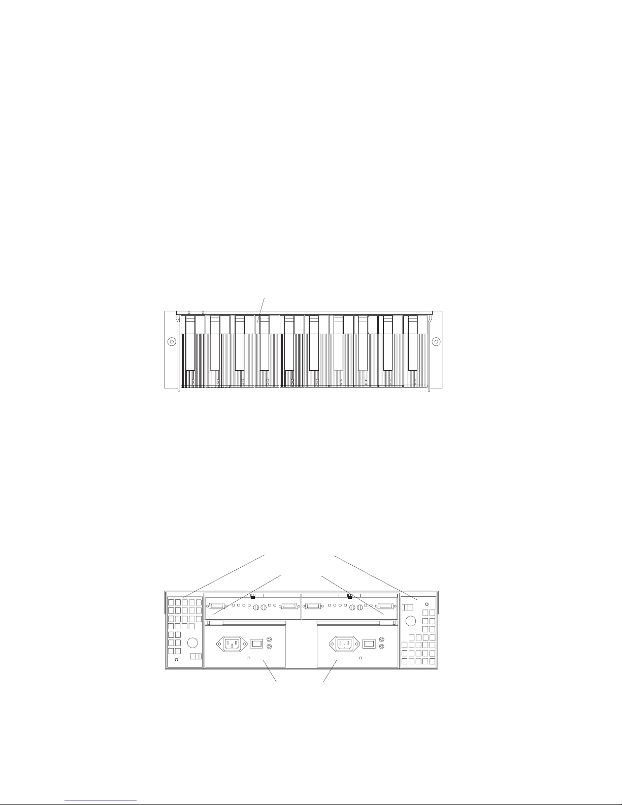
Back view
The following illustration shows the components at the back of the IBM NAS 300
RAID storage controller.
Hot-swap fan bays
Raid controllers
Hot-swap
power supplies
RAID controller
The RAID storage controller comes with one or two hot-swap RAID
controllers. Each RAID controller contains two ports for Gigabit Interface
Chapter 2. Introduction 7
Page 18
Converters (GBICs), which connect to the Fibre Channel cables. One GBIC
connects to a host system. The other GBIC is used to connect additional
storage units to the RAID controller.
Each RAID controller also contains a battery to maintain cache data in the
event of a power failure.
Hot-swap fans
The RAID controller has two interchangeable hot-swap and redundant fan
CRUs. Each fan CRU contains two fans. If one fan CRU fails, the second
fan CRU continues to operate. Both fan CRUs must be installed to maintain
proper cooling within your RAID controller, even if one fan CRU is not
operational.
Hot-swap power supplies
The RAID controller comes with two hot-swap power supplies. Both power
supplies must be installed to maintain proper cooling.
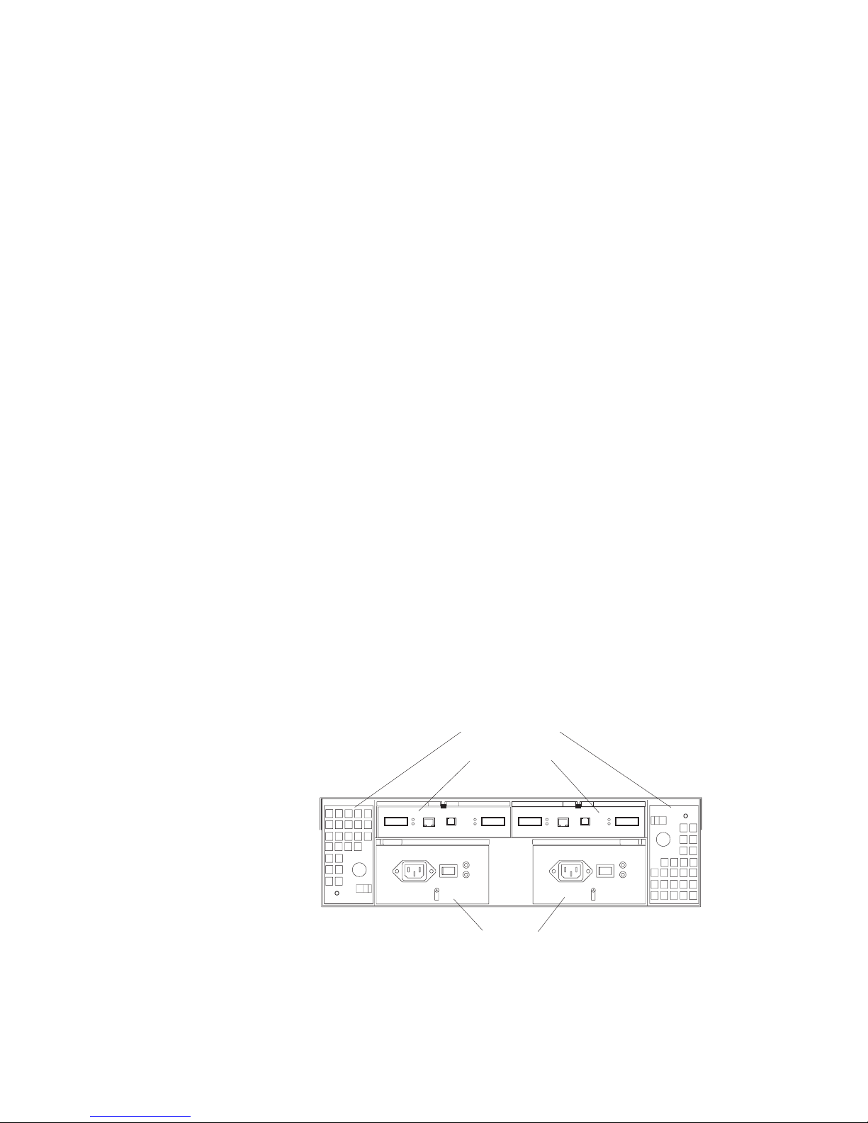
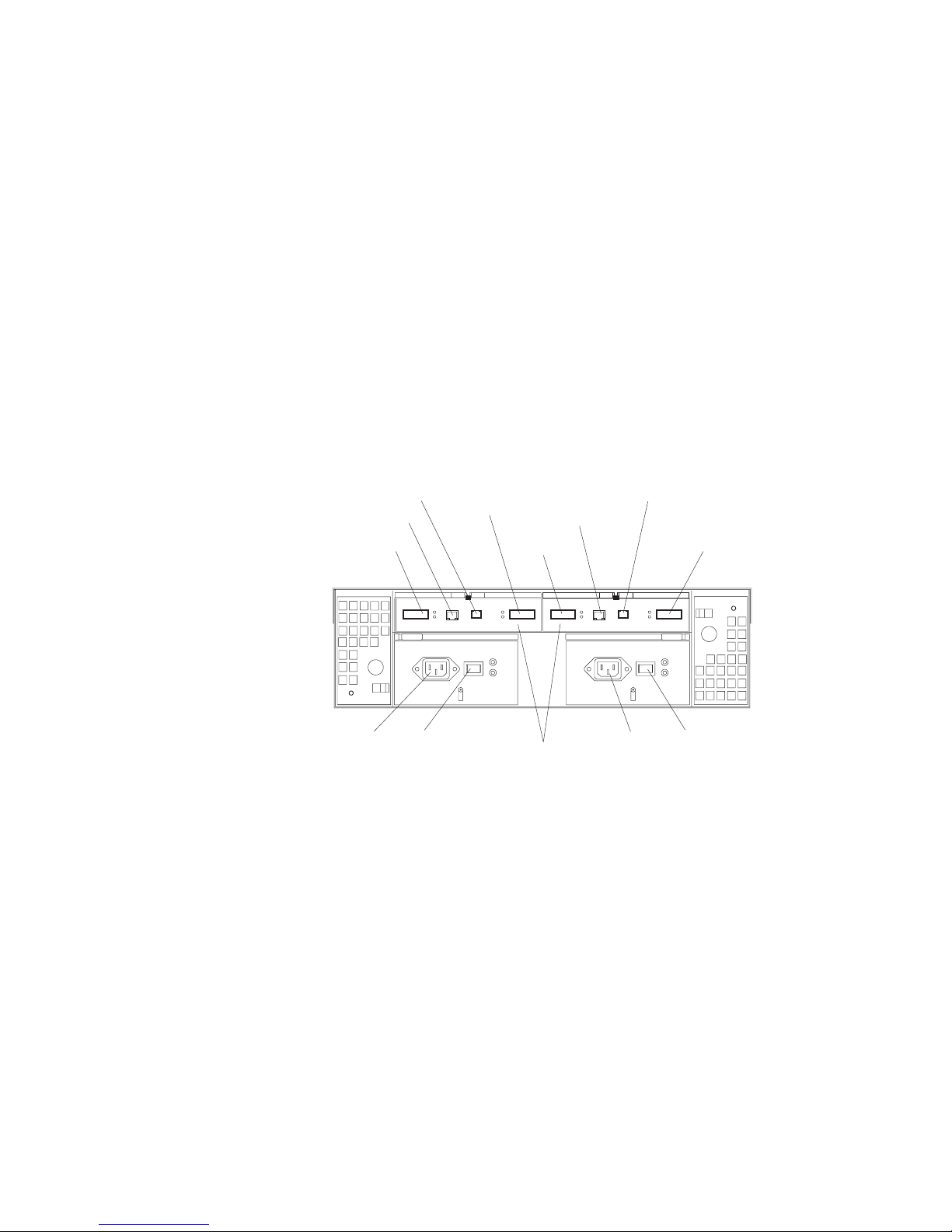
Interface ports and switches
The following illustration shows the ports and switches on the back of the RAID
controller.
Ethernet port
AC power
connector
RAID controller
Each RAID controller contains several connectors and LEDs. Each
controller has one host port and one expansion port for connecting the
storage server to hosts or expansion units. You first insert GBICs into the
ports and then connect the Fibre Channel cables.
Host port
The host port is used to connect a Fibre Channel cable from the IBM NAS
300 Fibre Channel hub. You first insert a GBIC into the port and then
connect a Fibre Channel cable.
RS-232 port
Host port
Expansion port
AC power
switch
Ethernet port
Host port
RAID controllers
RS-232 port
AC power
connector
Expansion port
AC power
switch
Ethernet port
The Ethernet port is for an RJ-45 10 BASE-T or 100 BASE-T Ethernet
connection. Use the Ethernet connection to directly manage storage
subsystems.
Expansion port
The expansion port is used to connect additional expansion units to the
RAID controllers. You first insert a GBIC into the port and then connect a
Fibre Channel cable.
8 IBM NAS 300 Service Guide
Page 19

Storage Unit
Features
RS-232 port
The RS-232 port is a TJ-6 modular jack and is used for an RS-232 serial
connection. The RS-232 port is used by service personnel to perform
diagnostic operations on the RAID controllers. An RS-232 cable comes with
the RAID storage controller.
The IBM NAS 300 storage unit is a compact unit that provides high-capacity, Fibre
Channel (FC) disk storage. It delivers fast, high-volume data transfer, retrieval, and
storage functions across multiple drives, to multiple hosts. The expansion enclosure
is designed for continuous, reliable service; the modular, redundant disk drives,
power supplies, ESM boards, and fans use hot-swap technology for easy
replacement without shutting down the system.
The storage unit supports redundant, dual-loop configurations. Optional external FC
cables and gigabit interface converters (GBICs) connect the RAID controller to the
storage unit.
By adding an additional RAID storage controller, you can add up to seven 10–drive
storage units to your IBM NAS 300.
Each storage unit includes the following standard features:
v Dual ESM boards: The environmental services monitor (ESM) boards contain the
expansion unit controls, switches, and LEDs. Each ESM board has two GBIC
ports for connecting the storage unit to the RAID storage controller.
v 10 Fibre Channel 40–pin disk drives.
v Dual power supplies and dual modular cooling fan assemblies.
Table 2. storage unit features
General
v Modular components:
– High-capacity disk drives
– Environmental services monitor
(ESM) boards
– Power supplies
– Cooling fans
v Technology:
– Supports disk arrays
– Supports clustering
– Fibre Channel host interface
– Redundant data storage,
cooling system, power system,
and ESM boards
– Hot-swap technology for drives,
power supplies, fans, and ESM
boards
v User interface:
– Built-in power, activity, and fault
indicators
– Identification labeling CRUs,
rear indicator lights, switches,
and connectors
– Easy-to-replace drives, power
supplies, ESM boards, and fans
Disk drive storage
Maximum drives per storage unit:
10
ESM boards
v Technology and interfaces:
– Fibre Channel: 40-pin FC disk
drives
– Fibre Channel interface: Four,
GBICs connectors for incoming
and outgoing FC cables (two
GBICs on each ESM board)
Chapter 2. Introduction 9
Page 20
Components
The following sections describe the components of the storage unit.
Note: The hot-swap features of the IBM NAS 300 storage unit enable you to
remove and replace hard disk drives, power supplies, ESM boards, and fans
without turning off the storage unit. Therefore, you can maintain the
availability of your system while a hot-swap device is removed or replaced.
Storage unit CRUs
This section lists the storage unit CRUs.
Hot-swap drives: The following illustration shows the location of the hot-swap
drive bays accessible from the front of your expansion unit. The storage unit
contains 10 slim 40-pin FC hard disk drives. These drives come preinstalled in drive
trays. This drive-and-tray assembly is called a drive CRU (customer replaceable
unit).
Hot-swap drive bays
Attention: Never hot-swap a drive CRU when its green Activity LED is flashing.
Hot-swap a drive CRU only when its amber Fault LED is completely on and not
flashing or when the drive is inactive with the green Activity LED completely on and
not flashing.
Fan, ESM, and power supply CRUs: The following illustration shows the location
of the hot-swap fan CRUs, the hot-swap ESM CRUs, and the hot-swap power
supply CRUs.
Hot-swap fan bays
ESM bays
Hot-swap power
supply bays
ESM CRUs
Your storage unit comes with two hot-swappable ESM boards. The ESM
boards provide a 1–Gb FC interface to the drives and monitors the overall
10 IBM NAS 300 Service Guide
Page 21
status of the storage unit. Each ESM board has two GBIC connector ports
for connecting your storage unit to the controller or connecting two or more
storage unit together. The ESM boards provide redundancy when both
boards are configured into redundant FC loops.
Hot-swap fan CRUs
Your storage unit has two interchangeable hot-swap and redundant fan
units. Each unit contains two fans. If one fan unit fails, the second fan unit
continues to operate. Both fan units must be installed to maintain proper
cooling within your expansion unit, even if one fan unit is not operational.
Hot-swap power supplies
Your storage unit comes with two hot-swap and redundant power supplies.
Both power supplies must be installed to maintain proper cooling within
your storage unit, even if one power supply is not operational.
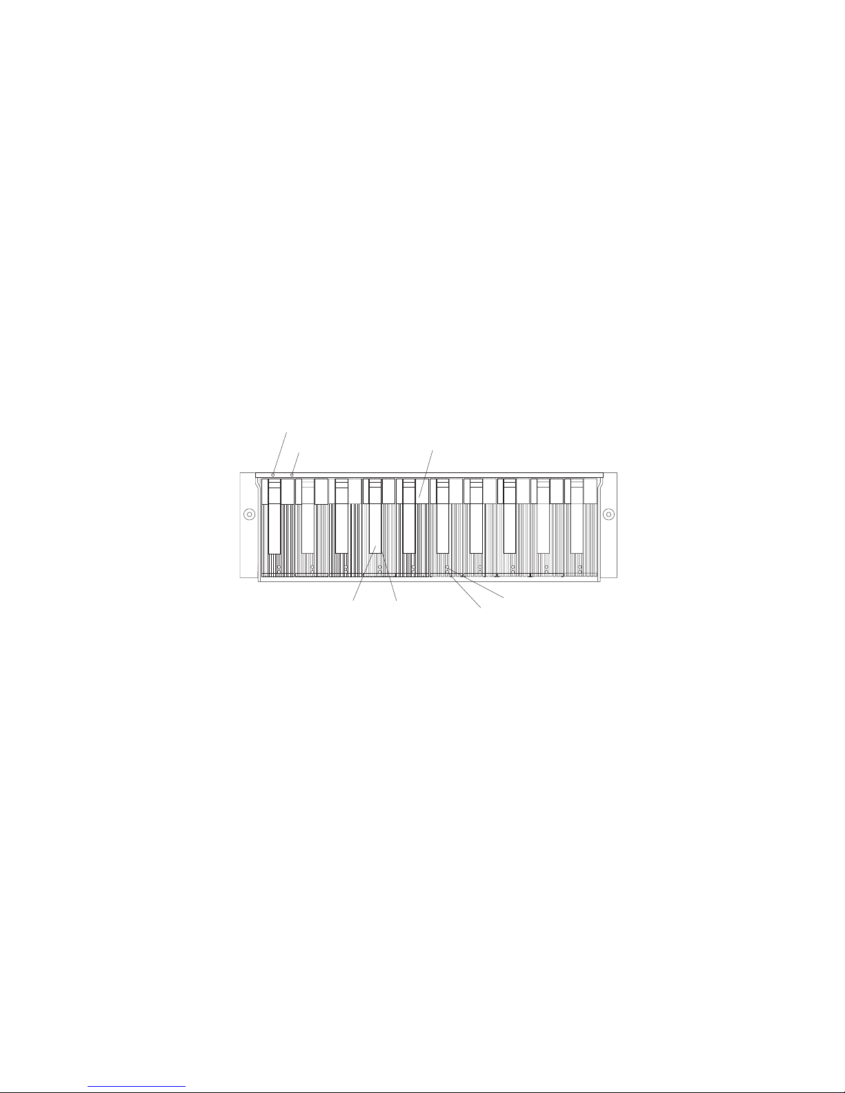
Front controls and indicators
The primary controls on the front of the storage unit are shown in the following
illustration.
Power-on LED
General-systemerror LED
Hot-swap
drive CRU
Tray handle
Latch
Drive activity LED
Drive fault LED
Activity LED
Each drive CRU has an Activity LED. When flashing, this green LED
indicates drive activity. When completely on, this green LED indicates the
drive is properly installed.
Drive CRU
Your storage unit comes standard with 10 hot-swap drive CRUs. Each drive
CRU consists of a hard disk drive and tray.
Fault LED
Each drive CRU has a Fault LED. When lit, this amber LED indicates a
drive failure. When flashing, this amber LED indicates that a drive Identify
or Rebuild process is in progress.
General system error LED
When lit, this amber LED indicates that the unit has a fault, such as in a
power supply, fan unit, or hard disk drive.
Latch This multipurpose blue latch releases or locks the drive CRU in place.
Power-on LED
When lit, this green light indicates that the unit has good dc power.
Tray handle
You can use this multipurpose handle to insert and remove a drive CRU in
the bay.
Chapter 2. Introduction 11
Page 22
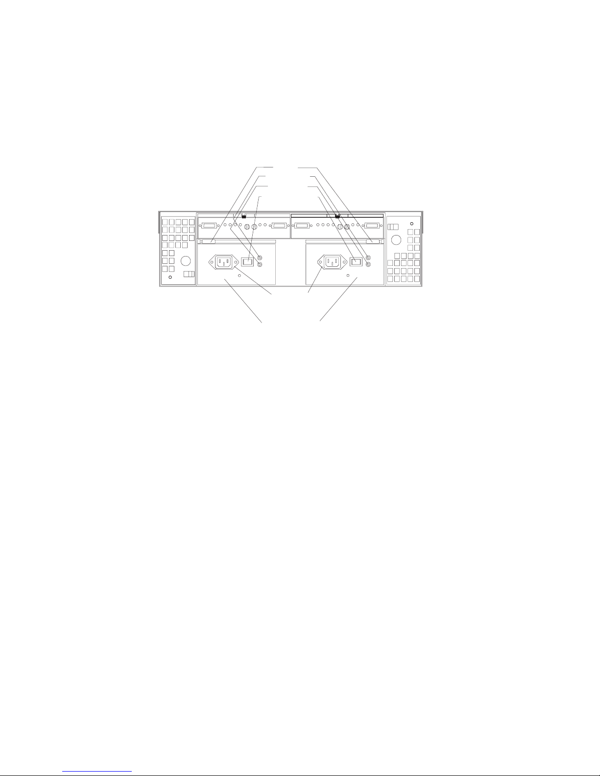
Rear controls, indicators, and connectors
Two hot-swap power supply CRUs, two hot-swap fan CRUs, and two ESM boards
are accessible from the back of the storage unit. These components contain several
controls, indicators, and connectors.
Power supply controls, indicators, and connectors:
Levers
Power LEDs
Fault LEDs
Power switches
AC power
connectors
Hot-swap power
supply bays
AC power connectors
The power cords for the power supplies connect here.
Fault LEDs
These amber Fault LEDs light if a power supply failure occurs or if the
power supply is turned off.
Levers
Use these locking handles to remove or install a power supply.
Power LEDs
These green LEDs light when the storage unit is turned on and receiving ac
power.
Power supply CRUs
The two hot-swap power supplies are located here. Both power supply
CRUs must be installed, even if one power supply is not operational.
Power switches
Use these switches to turn the power supplies on and off. You must turn
both switches on to take advantage of the redundant power supplies.
Fan controls and indicators: The fans in your storage unit are hot-swappable
and redundant. This means that your storage unit will continue to operate if a fan
fails. It also means that you can remove and replace the fan while the storage unit
is on and accessing drives.
Attention: The fans in your storage unit draw in fresh air and force out hot air.
These fans are hot-swappable and redundant; however, when one fan fails, the fan
unit must be replaced within 48 hours in order to maintain redundancy and optimum
cooling. When you replace the failed unit, be sure to install the second fan within 10
minutes to prevent any overheating due to the lack of the additional fan unit.
12 IBM NAS 300 Service Guide
Page 23
Fan CRUs
The two fan CRUs are located here. These fans are hot-swappable and
redundant.
Fault LEDs
These amber LEDs light when a fan failure occurs.
Latches and handles
Use the latches and handles to remove or install the fan CRUs.
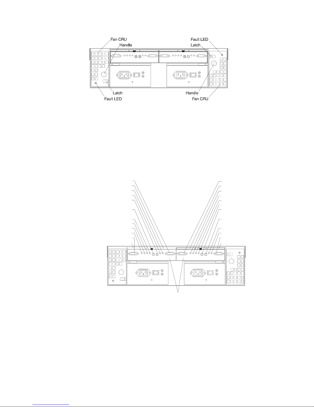
ESM boards user controls:
GBIC output port
Lever
Output bypass LED
ID conflict LED
Tray number
switch tens place (x10)
Tray number
switch ones place (x1)
Over-temperature LED
Fault LED
Power LED
Input bypass LED
GBIC input port
Lever
ESM boards
The environmental services monitor (ESM) boards contain the expansion
unit controls, switches, and LEDs. Each ESM board has two GBIC ports for
connecting the expansion unit to the controller.
ESM boards
GBIC input port
Lever
bypass LED
Input
Power LED
Fault LED
O
ver-temperature LED
Tray number
switch tens place (x10)
Tray number
switch ones place (x1)
ID conflict LED
Out put bypass LED
GBIC output port
Lever
Fault LEDs
GBIC input ports
These amber LEDs light when an ESM board failure occurs.
The two GBIC input ports are for attaching the optional GBICs to the
storage unit.
Chapter 2. Introduction 13
Page 24

GBIC output ports
The two GBIC output ports are for attaching the optional GBICs to the
storage unit.
The optional GBICs (input and output) are for attaching your optical cables
to the storage unit, then to the controller or additional storage unit. Insert
the GBICs in the expansion unit GBIC ports and attach your FC cables to
the GBICs, then connect the FC cables to the controller or additional
storage unit.
ID conflict LEDs
These amber LEDs light if the storage unit tray ID settings for the ESM
boards do not match. In this case, the storage unit uses the tray number of
the left ESM board.
Input/Output bypass LEDs
These amber LEDs light when no valid input signal is detected and when
no data is passed through the port. When no cable is connected to the port,
the LEDs also light. Both ports on the ESM board are bypassed and the
LEDs are lit in the event of an ESM board fault. In this case, the ESM Fault
LED is also lit.
Levers
Use these levers when removing and inserting the ESM boards.
Power LEDs
These green LEDs are lit when there is power to the ESM board.
Over-temperature LEDs
These amber LEDs light if the storage unit overheats.
Tray number switches
These switches assign the physical addresses of the disk drives and the
system management processors that are participating in the loop, and they
identify the storage unit. The base switch (x1) sets the IDs of the disk drives
on the loop. The settings of both the base ID switch (x1) and the extended
ID switch (x10) together is the storage unit ID. The switches set the storage
unit ID using values of 00 through 99. The base ID switch (x1) is for the
ones position and the extended ID switch (x10) is for the tens position.
Supported software applications
For a list of the pre-loaded and optional software applications that are supported by
your IBM NAS 300, refer to the IBM TotalStorage Network Attached Storage 300
User’s Reference.
14 IBM NAS 300 Service Guide
Page 25

Chapter 3. Troubleshooting
This chapter provides basic troubleshooting information to help you resolve some
common problems that might occur with your IBM NAS 300.
Note: The information is organized by IBM NAS 300 component (engines, Fibre
Channel hub, and so on); however, if a Fibre Channel hub or one or more
engines, RAID storage controllers, or storage units loses power to one power
supply, check the circuit breakers on the power distribution units (PDUs)
located inside the IBM NAS 300 left and right side covers.
Troubleshooting the engines
Diagnostic tools overview
The following tools are available to help you identify and resolve hardware-related
problems:
v POST beep codes, error messages, and error logs
The power-on self-test (POST) generates beep codes and messages to indicate
successful test completion or the detection of a problem. See “POST” on page 16
for more information.
v Diagnostic programs and error messages
The diagnostic programs are stored in upgradable read-only memory (ROM) on
the system board. These programs are the primary method of testing the major
components of your engine. See “Diagnostic programs and error messages” on
page 17 for more information.
Note: To view error messages, attach a monitor, keyboard, and mouse to the
each engine before it is powered-on.
v Light path diagnostics
Light-emitting diodes (LEDs) help you identify problems with engine components.
These LEDs are part of the light-path diagnostics that are built into your engine.
By following the path of lights, you can quickly identify the type of system error
that occurred. See “Light path diagnostics” for more information.
Identifying problems using LEDs
Each engine has LEDs to help you identify problems with some engine
components. These LEDs are part of the light path diagnostics built into the engine.
By following the path of lights, you can identify the type of system error that
occurred. See the following sections for more information.
Power supply LEDs
The ac and dc Power LEDs on the power supply provide status information about
the power supply. See “Power supply LED errors” on page 52.
Light path diagnostics
You can use the light path diagnostics to quickly identify the type of system error
that occurred. The diagnostics panel is under the ″wind tunnel.″ Each engine is
designed so that any LEDs that are On, remain On when the engine shuts down as
long as the ac power source is good and the power supplies can supply +5V dc
current to the engine. This feature helps isolate the problem if an error causes the
engine to shut down. See “Light path diagnostics table” on page 16.
© Copyright IBM Corp. 2001 15
Page 26

Diagnostics LED panel
DASD2
DASD1
VRM
PCI A
PCI B
CPU
MEM
FAN
TEMP
NMI
OVER
NON
PS3
PS2
PS1
The following illustration shows the LEDs on the diagnostics panel on the system
board. See “Light path diagnostics table” for information on identifying problems
using these LEDs.
Note: You need to remove the top cover (see “Removing the cover and bezel” on
page 70) to view these LEDs.
Light path diagnostics table
The System Error LED on the operator information panel is On when certain system
errors occur. If the System Error LED is On, use the following table to help
determine the cause of the error and the action to take. See table in “Information
panel system error LED” on page 48.
POST
When you power-on the engine, it performs a series of tests to check the operation
of its components and some of the options installed in the engine. This series of
tests is called the power-on self-test or POST.
If POST finishes without detecting any problems, one long beep and three short
16 IBM NAS 300 Service Guide
beeps sound.
If POST detects a problem, a series of beeps sound. See “Beep symptoms” on
page 45 and “POST error messages” on page 17 for more information.
Notes:
1. If you have a power-on password or administrator password set, you must type
the password and press Enter, when prompted, before POST will continue.
2. A single problem might cause several error messages. When this occurs, work
to correct the cause of the first error message. After you correct the cause of
the first error message, the other error messages usually will not occur the next
time you run the test.
Page 27

POST error messages
Note: To view POST error messages, attach a monitor, keyboard, and mouse to
each engine before it is powered-up.
The table,“POST error codes” on page 53, provides information about the POST
error messages that can appear during startup.
Event/error logs
The POST error log contains the three most recent error codes and messages that
the system generated during POST. The System Event/Error Log contains all error
messages issued during POST and all system status messages from the Advanced
System Management Processor. In event of a POST error, check the System
Event/Error Log as it may indicate the most recent errors commonly associated with
typical hardware failures. It may not detect all hardware failures but many times will
provide an indicator as to the nature of key failures.
To view the contents of the error logs, start the Configuration/Setup Utility program
(“Starting the Configuration/Setup Utility program” on page 111); then, select
Event/Error Logs from the main menu.
Diagnostic programs and error messages
The engine diagnostic programs are stored in upgradable read-only memory (ROM)
on the system board. These programs are the primary method of testing the major
components of your engine.
For a list of error messages and codes, see “Diagnostic error codes” on page 49.
Diagnostic error messages indicate that a problem exists; they are not intended to
be used to identify a failing part. Troubleshooting and servicing of complex
problems that are indicated by error messages should be performed by trained
service personnel.
Sometimes the first error to occur causes additional errors. In this case, the engine
displays more than one error message. Always follow the suggested action
instructions for the first error message that appears.
The following sections contain the error codes that might appear in the detailed test
log and summary log when running the diagnostic programs.
The error code format is as follows:
fff-ttt-iii-date-cc-text message
where:
fff is the three-digit function code that indicates the function being tested when
the error occurred. For example, function code 089 is for the
microprocessor.
ttt is the three-digit failure code that indicates the exact test failure that was
encountered.
iii is the three-digit device ID.
date is the date that the diagnostic test was run and the error recorded.
cc is the check digit that is used to verify the validity of the information.
Chapter 3. Troubleshooting 17
Page 28

text message
is the diagnostic message that indicates the reason for the problem.
Text messages
The diagnostic text message format is as follows:
Function Name: Result (test specific string)
where:
Function Name
is the name of the function being tested when the error occurred. This
corresponds to the function code (fff) given in the previous list.
Result
can be one of the following:
Test Specific String
This is additional information that you can use to analyze the problem.
Passed
This result occurs when the diagnostic test completes without any errors.
Failed This result occurs when the diagnostic test discovers an error.
User Aborted
This result occurs when you stop the diagnostic test before it is complete.
Not Applicable
This result occurs when you specify a diagnostic test for a device that is not
present.
Aborted
This result occurs when the test could not proceed because of the system
configuration.
Warning
This result occurs when a possible problem is reported during the
diagnostic test, such as when a device that is to be tested is not installed.
Starting the diagnostic programs
To start the diagnostic programs:
1. Ensure you have connected a monitor, keyboard, and mouse to each engine.
Notes:
a. When you do not have a monitor, keyboard, and mouse attached and the
engine passes POST, one long and three short beeps sound.
b. When you have a monitor, keyboard, and mouse attached and the engine
passes POST, one beep sounds. If the engine fails POST, a series of beeps
sound (see “Beep symptoms” on page 45 for more details) and an error
message appears on the monitor screen.
2. Power-on the engine and watch the screen.
3. When the message F2 for Diagnostics appears, press F2. If a POST error is
encountered, a series of beeps sound and an error message appears on the
monitor screen.
4. Type in the appropriate password; then, press Enter. If a system error is
encountered, the Configuration/Setup screen appears. Press Esc to start the
Diagnostic program.
Note: To run the diagnostic programs, you must start the engine with the
18 IBM NAS 300 Service Guide
highest level password that is set. That is, if an administrator password is
Page 29

set, you must enter the administrator password, not the power-on
password, to run the diagnostic programs.
5. Select either Extended or Basic from the top of the screen. (PC-Doctor 2.0 with
a copyright statement appears at the bottom of this screen.)
6. When the Diagnostic Programs screen appears, select the test you want to run
from the list that appears; then, follow the instructions on the screen.
Notes:
a. Press F1 while running the diagnostic programs to obtain Help information.
Also press F1 from within a help screen to obtain online documentation from
which you can select different categories. To exit Help and return to where
you left off, press Esc.
b. If the engine stops during testing and you cannot continue, restart the
engine and try running the diagnostic programs again.
c. If you run the diagnostic programs with either no mouse or a USB mouse
attached to your engine, you will not be able to navigate between test
categories using the Next Cat and Prev Cat buttons. All other functions
provided by mouse-selectable buttons are also available using the function
keys.
d. You can test the USB keyboard by using the regular keyboard test. The
regular mouse test can test a USB mouse. Also, you can run the USB hub
test only if there are no USB devices attached.
e. You can view engine configuration information (such as system
configuration, memory contents, interrupt request (IRQ) use, direct memory
access (DMA) use, device drivers, and so on) by selecting Hardware Info
from the top of the screen.
f. You cannot use the diagnostics program to test adapters. Use the procedure
outlined in “Running adapter diagnostics” on page 25.
When the tests have completed, you can view the Test Log by selecting Utility from
the top of the screen.
If the hardware checks out OK but the problem persists during normal engine
operations, a software error might be the cause. If you suspect a software problem,
refer to the information that comes with the software package.
Viewing the test log
The test log will not contain any information until after the diagnostic program has
run.
Note: If you already are running the diagnostic programs, begin with step 4
To view the test log:
1. Ensure a monitor, keyboard, and mouse is connected to each engine.
2. Power-on the engine and watch the screen.
If the engine is on, shut down your operating system and restart the engine.
3. When the message F2 for Diagnostics appears, press F2.
If a power-on password or administrator password is set, the engine prompts
you for it. Type in the appropriate password; then, press Enter.
4. When the Diagnostic Programs screen appears, select Utility from the top of
the screen.
5. Select View Test Log from the list that appears; then, follow the instructions on
the screen.
Chapter 3. Troubleshooting 19
Page 30

The system maintains the test-log data while the engine is powered-on. When
you power-off the power to the engine, the test log is cleared.
Diagnostic error message tables
For descriptions of the error messages that might appear when you run the
diagnostic programs see “Diagnostic error codes” on page 49.
Attention: If diagnostic error messages appear that are not listed in the tables,
make sure that your engine has the latest levels of BIOS, Advanced System.
Recovering BIOS
If your BIOS has become corrupted, such as from a power failure during a flash
update, you can recover your BIOS using the recovery boot block and a BIOS flash
diskette.
Note: You can obtain a BIOS flash diskette from one of the following sources:
v Download a BIOS flash diskette from the
website:www.storage.ibm.com/support/nas
v Contact your IBM service representative.
Troubleshooting the planar Ethernet controller
This section provides troubleshooting information for problems that might occur with
the 10/100 Mbps planar Ethernet controller.
Network connection problems
If the Ethernet controller cannot connect to the network, check the following:
v Ensure that you have the engine correctly connected to the Ethernet with a
verified cable that has been correctly built to the related Category 3, 4, or 5
unshielded twisted pair (UTP) standards.
The network cable must be securely attached at all connections. If the cable is
attached but the problem persists, try a different cable.
If you set the Ethernet controller to operate at 100 Mbps, you must use Category
5 cabling.
If you directly connect two workstations (without a hub), or if you are not using a
hub with X ports, use a crossover cable.
Note: To determine whether a hub has an X port, check the port label. If the
label contains an X, the hub has an X port.
v Ensure that heartbeat is inoperable on the adapter card or transceiver you are
using to connect to the Ethernet.
v If you are connecting through an Ethernet hub or repeater, validate that the
signal lights are operational while the device is on and connected to the LAN.
v Determine if the hub supports auto-negotiation. If not, try configuring the
integrated Ethernet controller manually to match the speed and duplex mode of
the hub.
v Check the Ethernet controller lights on the operator information panel.
These lights indicate whether a problem exists with the connector, cable, or hub.
– The Ethernet Link Status light is On when the Ethernet controller receives a
LINK pulse from the hub. If the light is Off, there might be a bad connector or
cable, or a problem with the hub.
– The Ethernet Transmit/Receive Activity light is On when the Ethernet controller
sends or receives data over the Ethernet Network. If the Ethernet
Transmit/Receive Activity light is Off, make sure that the hub and network are
operating and that the correct device drivers are loaded.
20 IBM NAS 300 Service Guide
Page 31

v Make sure that you are using the correct device drivers, supplied with your
engine.
v Check for operating system-specific causes for the problem.
v Make sure that the device drivers on the client and engine are using the same
protocol.
v Test the Ethernet controller by running the diagnostic program.
Ethernet controller troubleshooting chart
Use the following troubleshooting chart to find solutions to 10/100 Mbps Ethernet
controller problems that have definite symptoms.
Table 3. Ethernet troubleshooting chart
Ethernet controller problem Suggested Action
Ethernet Link Status light is
not On.
The Ethernet
Transmit/Receive Activity light
is not On.
Data is incorrect or sporadic. Check the following:
The Ethernet controller
stopped working when
another adapter was added to
the engine.
Check the following:
v Ensure that the hub is powered-on.
v Check all connections at the Ethernet controller and the hub.
v Check the cable. A crossover cable is required unless the hub has an X
designation.
v Use another port on the hub.
v If the hub does not support auto-negotiation, manually configure the Ethernet
controller to match the hub.
v If you manually configured the duplex mode, ensure that you also manually
configure the speed.
v Run diagnostics on the LEDs.
If the problem remains, go to “Starting the diagnostic programs” on page 18 to run
the diagnostic programs.
Check the following:
Note: The Ethernet Transmit/Receive Activity LED is On only when data is sent to or
by this Ethernet controller.
v Ensure that you have loaded the network device drivers.
v The network might be idle. Try sending data from this workstation.
v Run diagnostics on the LEDs.
v The function of this LED can be changed by device driver load parameters. If
necessary, remove any LED parameter settings when you load the device drivers.
v Ensure that you are using Category 5 cabling when operating the engine at 100
Mbps.
v Make sure that the cables do not run close to noise-inducing sources like
fluorescent lights.
Check the following:
v Ensure that the cable is connected to the Ethernet controller.
v Ensure that your PCI system BIOS is current.
v Reseat the adapter.
v Ensure that the adapter you are testing is supported by the engine.
Go to “Starting the diagnostic programs” on page 18 to run the diagnostic programs.
The Ethernet controller
stopped working without
apparent cause.
Check the following:
v Run diagnostics for the Ethernet controller.
v Try a different connector on the hub.
v Reinstall the device drivers. Refer to your operating-system documentation and to
If the problem remains, go to “Starting the diagnostic programs” on page 18 to run
the diagnostic programs.
the IBM NAS 300 User’s Reference information.
Chapter 3. Troubleshooting 21
Page 32

10/100 Ethernet Adapter troubleshooting chart
You can use the following troubleshooting chart to find solutions to 10/100 Mbps
Ethernet adapter problems that have definite symptoms.
Table 4. Ethernet troubleshooting chart
Ethernet adapter problem Suggested Action
The adapter cannot connect
to the network.
Diagnostics pass, but the
connection fails or errors
occur.
Check the following:
1. Ensure that the network cable is installed correctly. The cable must be securely
attached at both RJ-45 connections (adapter and hub). The maximum allowable
distance from adapter to the hub is 100 m (328 ft.). If the cable is attached and
the distance is within acceptable limits but the problem persists, try a different
cable. If you are directly connecting two computers without a hub or switch, make
sure you are using a crossover cable.
2. Check the LED lights on the adapter. The adapter has two diagnostic LEDs, one
on each side of the cable connector. These lights help you to determine whether
there is a problem with the connector, cable, switch, or hub.
ACT/LNK — On
v Adapter and switch is receiving power and cable connection between
them is good
ACT/LNK — Off
Check the following:
v Adapter not sending or receiving data
v Adapter or switch not receiving power
v Cable connection between adapter and switch is faulty
v Drivers not configured properly
ACT/LNK — Flashing
Normal operation. LED flashes when the adapter sends or receives data.
The frequency of the flashes varies with the amount of network traffic
100 — On
Adapter is operating at 100 Mbps
100 — Off
Adapter is operating at 10 Mbps
3. Ensure that you are using the correct drivers. Ensure that you are using the
drivers that come with this adapter. Drivers that support previous versions of this
adapter do not support this version of the adapter.
4. Ensure that the switch port and the adapter have the same duplex setting. If you
configured the adapter for full-duplex, ensure that the switch port is also
configured for full-duplex. Setting the wrong duplex mode can degrade
performance, cause data loss, or result in lost connections.
Check the following:
1. For 100 Mbps:
v Use Category 5 cabling and ensure that the network cable is securely
attached.
v Verify the adapter is seated firmly in the slot and connected to a 100BASE-TX
hub/switch (not 100BASE-T4).
2. Ensure the duplex mode setting on the adapter matches the setting on the switch
22 IBM NAS 300 Service Guide
Page 33

Table 4. Ethernet troubleshooting chart (continued)
Ethernet adapter problem Suggested Action
The LNK LED is not On. Check the following:
1. Ensure that you loaded the correct network drivers.
2. Check all connections at the adapter and the switch.
3. Try another port on the switch.
4. Ensure that the duplex mode setting on the adapter matches the setting on the
switch.
5. Ensure that you have the correct type of cable between the adapter and the hub.
100BASE-TX requires two pairs. Some hubs require a crossover cable while
others require a straight-through cable.
The ACT LED is not On. Check the following:
1. Ensure that you loaded the correct network drivers.
2. The network might be idle. Try accessing a server.
3. The adapter is not transmitting or receiving data. Try another adapter.
4. Ensure that you are using two-pair cable for TX wiring.
Adapter stops working without
apparent cause.
The LNK LED is not On when
you connect the power.
Check the following:
1. Run the diagnostics.
2. Try reseating the adapter in its slot, or try a different slot if necessary.
3. The network driver files might be corrupt or missing. Remove and then reinstall
the drivers.
Check the following:
Ensure that the network cable is securely attached at both ends.
Gigabit Ethernet SX adapter troubleshooting chart
Use the following troubleshooting chart to find solutions to gigabit Ethernet adapter
problems that have definite symptoms.
Chapter 3. Troubleshooting 23
Page 34

Table 5. Ethernet troubleshooting chart
Gigabit adapter problem Suggested Action
No Link or TX/RX Activity If you cannot link to your switch, check the following:
1. Check the following LED lights on the adapter:
TX — On
The adapter is sending data
RX — On
The adapter is receiving data.
Link — On
The adapter is connected to a valid link partner and is receiving link
pulses.
Link — Off
Link is inoperative.
v Check all connections at the adapter and link partner
v Make sure the link partner is set to 1000 Mbps and full-duplex
v Ensure the required drivers are loaded
PRO — Programmable LED
Identifies the adapter by blinking. Use the Identify Adapter push-button in
INTEL PROSet II to control blinking.
2. Ensure that the cable is installed correctly. The network cable must be securely
attached at all connections. If the cable is attached but the problem persists, try a
different cable.
Your engine cannot find the
Gigabit Ethernet SX adapter
Diagnostics pass but the
connection fails
Another adapter stopped
working after you installed
the Gigabit Ethernet SX
Adapter
The adapter stopped working
without apparent cause
LINK LED is not On Check the following:
Check the following:
1. Verify that the adapter is seated firmly in the slot
2. Try a different Gigabit Ethernet SX adapter
Check the following:
Ensure the network cable is securely attached
Check the following:
1. Verify that the cable is connected to the Gigabit Ethernet SX Adapter and not to
another adapter.
2. Check for a resource conflict
3. Ensure both adapters are seated firmly in the slot
4. Check all cables
Check the following:
1. Try reseating the adapter
2. The network driver files might be damaged or deleted. Reinstall the drivers
3. Try a different Gigabit Ethernet SX Adapter
1. Ensure that you have loaded the adapter driver
2. Check all connections at the adapter and the buffered repeater or switch
3. Try another port on the buffered repeater or switch
4. Ensure that the buffered repeater or switch port is configured for 1000 Mbps and
full-duplex.
5. Try changing the auto-negotiation setting on the link partner, if possible
24 IBM NAS 300 Service Guide
Page 35

Table 5. Ethernet troubleshooting chart (continued)
Gigabit adapter problem Suggested Action
RX or TX LED is no On Check the following:
1. Ensure that you have loaded the adapter driver
2. Network might be idle; try logging in from a workstation
3. The adapter is not transmitting or receiving data; try another adapter
Running adapter diagnostics
This section describes how to test the adapters using the diagnostics tools.
This section describes how to test the adapters using the diagnostics tools.
Testing the Ethernet adapters with Intel PROSet II
Each IBM NAS 300 engine comes with Intel PROSet II. You can use PROSet to
view the following:
v Adapter parameters such as MAC and IP addresses
v Network link status such as speed, duplex mode, and activity
v Device-driver level used for the adapter
You can also use PROSet II to test the 10/100 Ethernet and GB Ethernet PCI
adapters for any problems with the adapter hardware, cabling, or network
connections. PROSet performs a loopback test on the 10/100 Ethernet and GB
Ethernet PCI cards.
To access the PROSet II utility, go into Terminal Services. For instructions on how
to invoke Terminal Services. Within Terminal Services do the following steps:
1. Go to the Start menu, select Settings, then Control Panel.
2. Double-click the INTEL PROSet II icon in the Control Panel to start the INTEL
PROSet II utility.
3. In the INTEL PROSet II utility, select the Ethernet adapter you want to test
(Gigabit Ethernet PCI adapter or 10/100 Ethernet Adapter).
4. Select the Diagnostics tab. A list of available tests is displayed.
5. Select Run Tests. You can also select or deselect individual tests with the
check boxes. If an error is detected, information about the error is displayed.
6. Repeat Steps 3 through 5 for each Ethernet adapter installed.
For additional information about Intel PROSet, please refer to the online help that
accompanies the utility.
Testing the fibre-channel host adapter with FAStT Check
Note: Ensure that there is no adapter activity before running the test or data can
be lost.
The IBM NAS 300 engine also comes with FAStT Check for viewing the status of
the Fibre Channel connection as well as testing the adapter or cable. To use FAStT
Check, you should first go into Terminal Services.
You access FAStT Check by going into the IBM NAS Admin console, selecting NAS
Management → Storage → NAS Utilities → FAStT Check. Then, select Connect.A
diagnostic panel displays the following general information related to the Fibre
Channel adapter which can be useful if you need to place a support call:
Chapter 3. Troubleshooting 25
Page 36

v Node name
v Serial number (in hex)
v Loop ID
v BIOS version
v Firmware version number
v Device driver version number
v PCI slot number
FAStT Check also provides the engine’s world-wide name (WWN) as detailed in the
IBM NAS 300 User’s Reference..
To test the Fibre Channel adapter, select the adapter and then click the Diagnostic
button. FAStT Check can perform fibre loopback and data tests.
For additional information relating to FAStT Check diagnostic functions, refer to the
online help accessed from its panels.
Checking the FAStT host-bus adapter’s fibre-channel connectivity: In addition
to the above diagnostic function, you can use FAStT Check to determine if your
physical fibre channel connections are in place by doing the following steps:
1. Once Connected with FAStT as above, select the QLA2200 Adapter icon, and
verify that you see all Fibre Controllers that you are physically connected to. If
you see a red X on the QLA2200 Adapter icon, and the icon is yellow, the
adapter cannot register with the 3534 Fibre Channel hub. (A green icon means
connections are in place.) Check the fibre cable connections, and if the
QLA2200 adapter still does not connect, run the adapter and 3534 Fibre
Channel hub diagnostics.
2. If the icon is green, click on the plus sign (+) in front of the adapter icon to see
the state of the attached Fibre channel storage controllers. The absence of
controllers in the display indicates connection problems.
For additional information relating to FAStT Check diagnostic functions, refer to the
online help accessed from its panels.
Testing the Advanced System Management adapter
1. Insert the Advance System Management Utility CD-ROM into the CD-ROM drive
and restart the engine. If the engine does not boot from the CD-ROM, use
POST/BIOS setup to configure the CD-ROM drive as a boot device.
2. After your engine boots, the main option menu appears. The main menu
contains the following selections:
v Hardware Status and Information
v Configuration Settings
v Update System Management firmware
3. Use the up and down arrow keys to select Hardware Status and Information
and press Enter. The Hardware Status and Information menu contains the list
of Advanced System Management devices in the Gateway with the following
diagnostic test results:
26 IBM NAS 300 Service Guide
System Management Processor Communication : Passed
-> Built in Self Test Status ...... : Passed
Boot Sector Code Revision ... :6, Build ID: RIET62A
Main Application Code Revision :4, Build ID: ILET15A
Page 37

System Management Processor Communication : Passed
-> Built in Self Test Status ...... : Passed
Boot Sector Code Revision ... :6, Build ID: WMICT60A
Main Application Code Revision :4, Build ID: WMXT57A
4. Use the up and down arrow keys to select the device you want to look at in
more detail. Press Enter. You will see a list of tests and results on the device:
Current System Management Processor Status
Current BIST Results:
SRAM Memory Test: Passed
Serial Port 1 Test : Passed
Serial Port 2 Test: Passed
NVRAM Memory Test Passed
Realtime Clock Test Passed
Programmable Gate Array Test: Passed
I2C Interface Test: Passed
Main Application Checksum: Passed
Boot Sector Checksum: Passed
Current System Management Adapter Status
Current BIST Results:
SRAM Memory Test: Passed
Serial Port 1 Test : Passed
Serial Port 2 Test: Passed
NVRAM Memory Test Passed
Realtime Clock Test Passed
Programmable Gate Array Test: Passed
I2C Interface Test: Passed
Main Application Checksum: Passed
Boot Sector Checksum: Passed
Onboard Ethernet Hardware Test: Passed
PCI EEPROM Initialization Test: Passed
5. When you are finished viewing this information, press Esc to return to the main
option menu. Remove the CD then restart the engine.
Power checkout
Power problems can be difficult to troubleshoot. For example, a short circuit can
exist anywhere on any of the power distribution busses. Usually a short circuit
causes the power subsystem to shut down because of an overcurrent condition.
A general procedure for troubleshooting power problems is as follows:
1. Power-off the system and disconnect the ac cord(s).
2. Check for loose cables in the power subsystem. Also check for short circuits, for
example, if there is a loose screw causing a short circuit on a circuit board.
3. Remove adapters and disconnect the cables and power connectors to all
internal and external devices until the engine is at minimum configuration
required for power-on (see ″Minimum operating requirements″ on page 62).
4. Reconnect the ac cord and power-on the engine. If it powers up successfully,
replace adapters and devices one at a time until the problem is isolated. If the
engine does not power-up from minimal configuration, replace FRUs of minimal
configuration one at a time until the problem is isolated.
To use this method it is important to know the minimum configuration required to
power-up an engine (see page 62). For specific problems, see “Power error
messages” on page 59.
Chapter 3. Troubleshooting 27
Page 38

Replacing the battery
IBM has designed this product with your safety in mind. The lithium battery must be
handled correctly to avoid possible danger. If you replace the battery, you must
adhere to the following instructions.
CAUTION: When replacing the battery, use only IBM Part Number 10L6432 or
Note: In the U.S., call 1-800-IBM-4333 for information about battery disposal.
If you replace the original lithium battery with a heavy-metal battery or a battery with
heavy-metal components, be aware of the following environmental consideration.
Batteries and accumulators that contain heavy metals must not be disposed of with
normal domestic waste. They will be taken back free of charge by the manufacturer,
distributor, or representative, to be recycled or disposed of in a proper manner.
an equivalent type battery recommended by the manufacturer. If
your system has a module containing a lithium battery, replace it
only with the same module type made by the same manufacturer.
The battery contains lithium and can explode if not properly used,
handled, or disposed of.
Do not:
v Throw or immerse into water
v Heat to more than 100°C (212°F)
v Repair or disassemble
Dispose of the battery as required by local ordinances or regulations.
Note: Before you begin be sure to read any special handling and installation
instructions supplied with the replacement battery.
Note: After you replace the battery, you must reconfigure your engine and reset the
system date and time.
To replace the battery:
1. Review any special handling and installation instructions supplied with the
replacement battery.
2. Power-off the engine and peripheral devices and disconnect all external cables
and power cords; then, remove the engine cover.
3. Remove the battery:
a. Use one finger to lift the battery clip over the battery.
b. Use one finger to slightly slide the battery from its socket. The spring
mechanism behind the battery will push the battery out toward you as you
slide it from the socket.
c. Use your thumb and index finger to pull the battery from under the battery
clip.
d. Ensure that the battery clip is touching the base of the battery socket by
pressing gently on the clip.
28 IBM NAS 300 Service Guide
Page 39

4. Insert the new battery:
a. Tilt the battery so that you can insert it into the socket, under the battery
clip.
b. As you slide it under the battery clip, press the battery down into the socket.
5. Reinstall the engine cover and connect the cables.
Note: Wait approximately 20 seconds after you plug the power cord of your
6. Power-on the engine.
7. Start the Configuration/Setup Utility program and set configuration parameters.
v Set the system date and time.
v Set the power-on password.
v Reconfigure your engine.
Temperature checkout
Correct cooling of the engine is important for proper operation and reliability. Ensure
that:
v Each of the drive bays has either a drive or a filler panel installed
v Each of the power supply bays has either a power supply or a filler panel
installed
v The top cover is in place during normal operation
v There is at least 50 mm (2 inches) of ventilated space at the sides of the engine
and 100 mm (4 inches) at the rear of the engine.
v The top cover is removed for no longer than 30 minutes while the engine is
operating
v The processor housing cover covering the processor and memory area is
removed for no longer that ten minutes while the engine is operating
v A removed hot-swap drive is replaced within two minutes of removal
v Cables for optional adapters are routed according to the instructions provided
with the adapters (ensure that cables are not restricting air flow)
v The fans are operating correctly and the air flow is good
v A failed fan is replaced within 48 hours
engine into an electrical outlet for the Power Control button to become
active.
In addition, ensure that the environmental specifications for the engine are met.
For more information on specific temperature error messages, see “Temperature
error messages” on page 58.
Chapter 3. Troubleshooting 29
Page 40

Troubleshooting the Fibre Channel hub
Attention: If you are going to service a functional Fibre Channel hub, never
unplug cables or GBICs when there is activity on the associated ports. This will
cause immediate failure of the communications path. To determine if a port has
active communications, see “Visually inspect LEDs” If it becomes necessary to
unplug active ports, the you must stop communications on these ports.
Always begin problem determination by checking the following areas.
v System reported error or failure to access a device
v Visually inspect LEDs
v Determine if zoning is in effect
v Check for problems on attached devices
Before performing any repair action, gather as much information as possible.
System reported error or failure to access a device
Either the customer has reported a IBM NAS 300 related system error message or
the customer has reported a failure accessing IBM NAS 300 storage. If the host
reported error message from the IBM NAS 300 is known, or a customer
communications failure symptom is known, see Table 6 on page 31 After identifying
the error message or the symptom, perform the recommended service action.
Visually inspect LEDs
Observe the front panel LED status indicators, then check the information in Table 6
on page 31. If a faulty condition is observed, perform the recommended service
action.
Check for problems on attached devices
To determine if the source of the problem is an attached device, check the
following:
v LEDs
v Display panels
v Firmware levels
Checking the Fibre Channel hub
Attention: Do not remove cables or GBIC from ports that are:
v Blinking green: This is a normally operating port with communications in
progress.
v Steady green: The port is connected to a functional device, but there is no data
traffic in progress. If this port is believed to be the problem, the failure is not with
the Fibre Channel hub. Instead, the attached device or host is not attempting to
send data. See the appropriate host, device, or application documentation to
resolve the problem.
Use the following procedure to ensure that the Use the following procedure to
ensure that the Fibre Channel hub is good.
1. Remove the incoming cables from the suspect ports. Mark them to make sure
that you can return them to the same port.
2. Remove and reseat the GBIC in port 7 if it is installed.
30 IBM NAS 300 Service Guide
Page 41

3. Insert one of the small single GBIC port wrap connectors (black for ports0-6).
For port 7 the connector is black if the GBIC is short wavelength or gray if it is
long wavelength). Wait 10 seconds and observe the associated port LED. If it is
slowly blinking green (every 2 seconds), the GBIC and port are functional. Do
this for all suspect ports.
4. If all ports show a slow blinking green (blinks every 2 seconds), port LED, check
the customer configuration information or the associated fibre-channel cables.
See “Checking the customer configuration (action code 6)” on page 34 and
“Suspect fibre-channel cable (action code 7)” on page 34.
5. If any of the LEDs for ports0-6donotblink green, replace the Fibre Channel
hub. See “Working with the Fibre Channel hub” on page 110. If the LED for port
7 does not blink green, replace the GBIC, then continue with step 6.
6. After replacing the GBIC in port 7, insert the single port-wrap connector. If the
port LED still does not blink green, replace the Fibre Channel hub. See
“Working with the Fibre Channel hub” on page 110.
Service References
Table 6 lists the types of error messages or failure indications that might be
encountered. For the recommended action, see the corresponding action code in
Table 7 on page 32.
Table 6. Service reference table
Description Action Code
System reported error message
The customer has reported that a fan failure was reported to the
system.
Customer reports a failure to communicate with a host or device
Communication failure on all ports 2
Communication failure on some ports 3
Visual LED observation
Slow yellow blink port LED (2 second blink) 3
Fast yellow blink port LED (1/2 second blink) 3
Steady yellow port LED 3
Slow green blink port LED (2 second interval) 3
Fast green blink port LED (1/2 second interval) 3
Steady green port LED (port is online and the connected host/device is
not sending data)
Flickering green port LED (port is online and the connected host/device
is sending data
Interleaving green/yellow port LED (port is bypassed) 5
Port LED is off on port 7 (and a GBIC and cable are installed) 3
Port LED is off on port 7 (no GBIC installed) 0
Port LED is off on port 7 (GBIC installed but no cable) 3
Ready LED is anything other than steady green 3
Port LED is off on port 0, 1, 2, 3, 4, 5, or 6 (and a cable is installed) 3
Port LED is off on port 0, 1, 2, 3, 4, 5, or 6 (but no cable is installed) 3
1
0
0
Chapter 3. Troubleshooting 31
Page 42

Action Codes
Table 7 lists the action codes and the recommended actions.
Table 7. Action codes
Action code Action
0 Normal, no action required
1 See “Fan failure (action code 1)”
2 See “All ports fail to communicate (action code 2)”
3 See “Abnormal port LED/Function (action code 3)”
4 See “Abnormal Ready LED (action code 4)” on page 34
5 See “Port in bypass mode (action code 5)” on page 34
6 See “Checking the customer configuration (action code 6)” on page 34
7 See “Suspect fibre-channel cable (action code 7)” on page 34
Fan failure (action code 1): This service action is due to a customer call
regarding a hub message to the system that indicates a fan failure has occurred or
you suspect a fan failure for another reason. Replace the Fibre Channel hub. See
“Working with the Fibre Channel hub” on page 110.
All ports fail to communicate (action code 2): This service call is due to a
complete failure (no data can be passed through the hub).
1. Observe the front of the Fibre Channel hub. If the ready LED is on and steadily
green, see “Abnormal port LED/Function (action code 3)”.
If not, verify the following:
a. The power cord is seated.
b. There is power in the electrical outlet.
DANGER
An electrical outlet that is not correctly wired could place hazardous
voltage on metal parts of the system or the products that attach to the
system. It is the customer’s responsibility to ensure that the outlet is
correctly wired and grounded to prevent an electrical shock.
(72XXD201)
2. If the LED is now on, unplug the unit from the electrical outlet, wait 15 seconds,
then plug the unit into the electrical outlet.
3. If the ready LED is not on and steadily green, replace the entire 3534 Managed
Hub. See “Working with the Fibre Channel hub” on page 110.
Abnormal port LED/Function (action code 3): You are here for one of the
following reasons:
v You started from the action code for a total hub failure, and observed the ready
LED was functioning normally
v The customer reported that only some ports were failing while others were
operating.
v You observed an abnormal LED status on one or more ports.
Be sure that all cables and GBICs are properly seated. Observe the LEDs for the
failing ports. If you do not know which ports are failing, go to “Checking the Fibre
Channel hub” on page 30.
32 IBM NAS 300 Service Guide
Page 43

1. If the port LED blinks slow yellow (blinks every two seconds), the port is
disabled. The customer needs to re-enable the port using the Storwatch
Managed Hub Specialist Web interface or a Telnet session. See the IBM NAS
300 User’s Reference for information on disabling and re-enabling ports. Have
the customer re-enable the port.
2. If the port LED blinks fast yellow (blinks every 1/2 second), perform the
following steps:
a. Remove the incoming cables from the failing ports. Mark them to ensure
that you can return them to the same port.
b. If the port is port 7, remove and reseat the GBIC.
c. Insert one of the small single GBIC port wrap connectors (black for ports 0 -
6). For port 7, the connector is black if the GBIC is short wavelength or gray
if it is long wavelength. Wait 10 seconds and observe the associated port
LED. If it is blinking green, the GBIC and port are functional. Do this for all
suspect ports. If all ports show a blinking green port LED, check the other
customer configuration information or the associated fibre-channel cables.
See “Checking the customer configuration (action code 6)” on page 34 and
“Suspect fibre-channel cable (action code 7)” on page 34
d. If any of the LEDs for ports0-6donotblink green, replace the Fibre
Channel hub. See “Working with the Fibre Channel hub” on page 110. If the
LED for port 7 does not blink green, replace the GBIC with a new (known
good) GBIC.
e. After replacing the GBIC in port 7, again insert the single port wrap
connector. If the port LED still does not blink green, replace the Fibre
Channel hub. See “Working with the Fibre Channel hub” on page 110.
3. If the port LED is steady yellow, this indicates that the port is receiving a signal,
but the attached device is not yet online, and the device is likely not in the
ready state. Have the customer make the device ready. If the customer is
unable to correct the problem, see “Abnormal port LED/Function (action code
3)” on page 32.
4. If the port LED blinks a fast green (1/2-second blink, not a flickering light),
replace the Fibre Channel hub. See “Working with the Fibre Channel hub” on
page 110
5. If the port LED blinks slow green (2-second blink), it indicates that a bad cable
or a wrap cable is installed. Perform the following steps:
a. Verify if a wrap cable is installed or if a wrap connector is installed at the
other end of the cable. If either of these situations is true, correct it.
b. If a wrap cable or wrap connector is not installed, replace the cable or ask
the customer to have his cabling supplier check the cable, whichever is
appropriate.
6. Iftheport0-6LEDs show no light with no cable installed, or if port 7 shows no
light with a GBIC installed but no cable, perform the following steps:
a. This is normal. A cable from an appropriate device needs to be installed if
the port is to be used.
b. If the device cable is present, insert the cable into the GBIC or port.
7. If the port LED shows no light and a cable is installed, make sure that the
attached device is turned on and ready.
8. If the attached device is turned on and ready, it is necessary to check other
customer configuration information, or the associated fibre-channel cables. See
“Checking the customer configuration (action code 6)” on page 34 and “Suspect
fibre-channel cable (action code 7)” on page 34.
Chapter 3. Troubleshooting 33
Page 44

Abnormal Ready LED (action code 4): You are here because you have seen an
abnormal indication for the ready LED.
1. Verify the following:
a. The power cord is seated.
b. There is power in the electrical outlet.
DANGER
An electrical outlet that is not correctly wired could place hazardous
voltage on metal parts of the system or the products that attach to
the system. It is the customer’s responsibility to ensure that the
outlet is correctly wired and grounded to prevent an electrical
shock. (72XXD201)
2. If the LED is now on, unplug the unit from the electrical outlet; wait 15 seconds,
then plug the unit back into the electrical outlet.
3. If the ready LED is not on and steadily green, replace the entire 3534 Managed
Hub. See “Working with the Fibre Channel hub” on page 110.
Port in bypass mode (action code 5): The port is in bypass mode because it
has been unable to initialize the link.
1. Remove the cable from the port. The LED should go off.
v If the LED goes off, go to step 2.
v If the LED stays interleaving green and yellow, go to step 3.
v If the LED goes to some other state, note the new state and refer to
“Appendix F. Fibre Channel hub Diagnostics” on page 141 to determine
correct action.
2. The LED is off. This state is normal operation for the Fibre Channel hub. When
the cable was connected, the LED was interleaving green and yellow, indicating
that the port was not receiving correct information over the fiber link to enable it
to correctly initialize the link. See the appropriate manual for the device at the
other end of the cable, and resolve why a valid link initialization frame is not
being sent.
3. When the cable is removed, the LED should go to off. However, if it interleaves
green and yellow, there is a problem with the hub.
v If the interleaving port is 0 through 6, you must replace the hub. See
“Working with the Fibre Channel hub” on page 110.
v If the interleaving port is port 7, replace the GBIC and see if this resolves the
problem. If replacing the GBIC module does not solve the problem, you must
replace the Fibre Channel hub. See “Working with the Fibre Channel hub” on
page 110.
Checking the customer configuration (action code 6):
1. Check the customer configuration to ensure that the customer has appropriately
configured any systems, HBAs, storage devices, and code levels.
2. The HBAs should be running in FCAL mode. You should run diagnostics as
available on the systems HBAs.
If the HBAs are correctly configured and pass diagnostics, and you have not
found any fault with the Fibre Channel hub after reviewing and following all
other instructions in the service procedures, you might need to replace the
fibre-channel cable. Go to “Suspect fibre-channel cable (action code 7)”.
Suspect fibre-channel cable (action code 7):
34 IBM NAS 300 Service Guide
Page 45

1. Verify that the ends of the suspect cable are fully seated and that the pair of
fibre connectors are correctly oriented at both ends of the cable. You can easily
check this by swapping the two fibres at one end to see if this corrects the
problem. If this does not correct the problem, be sure to restore the fibre cables
to their original configuration.
2. If the HBA does not have wrap capability and you have access to both ends of
the cable, you can check it by plugging it into two short wavelength ports on the
same Fibre Channel hub, if available. Make sure that twice the cables length is
less than 500 m for short wavelength to do this test. Many bad cables can be
detected by simply plugging them into two ports and observing the port indicator
LEDs. The LEDs should blink slow green (blinks every 2 seconds). If they do
not, the cable is bad.
3. If the host or device HBA has a diagnostic to wrap a cable, perform this
diagnostic. If the diagnostic still reports failure, replace the cable or have the
customer replace the cable.
v If this is an IBM-provided cable, replace the cable. There are two lengths of
cable available for the Fibre Channel hub (5-meter and 25-meter short wave).
If these are appropriate, replace the cable.
v If the cables were obtained from some other IBM product, you need to
determine the appropriate FRU.
v If the customer obtained the cable from someone other than IBM, the
customer needs to replace the cable.
4. If the LED slowly blinks green, you can test it further by using the Cross Port
diagnostic test. See “Appendix F. Fibre Channel hub Diagnostics” on page 141.
5. If it is not possible or not appropriate to access the Fibre Channel hub in this
way, replace the short cable. If you are dealing with a long cable or one where
both ends cannot be accessed at the Fibre Channel hub, you need to have the
cable installer test the cable.
“Appendix F. Fibre Channel hub Diagnostics” on page 141describes additional
diagnostic procedures information including detailed diagnostic tests.
Troubleshooting the RAID storage controllers and storage units
IBM NAS 300 contains a Java-based storage management tool that manages,
monitors and diagnoses the IBM NAS 300 RAID storage controllers and storage
units. This tool provides an interface for storage management based on information
supplied by the storage subsystem controllers. This tool, called SM7, is accessed
on the IBM NAS 300 by using Windows Terminal Services which can be reached
through UM Services using TCP/IP port 1411 or directly through Terminal Services
via TCP/IP port 8099 or by using a directly attached keyboard and display. SM7
sends commands to the storage subsystem controllers. The controller firmware
contains the necessary information to carry out the storage-management
commands. The controller is responsible for validating and running the commands
and providing status and configuration information back to the client software.
The storage-management software provides the best way to diagnose and repair
storage server failures. The software can help you:
v Determine the nature of the failure
v Locate the failed component
v Determine the recovery procedures to repair the failure
Although the storage server has fault LEDs, these lights do not necessarily indicate
which component has failed or needs to be replaced, or which type of recovery
Chapter 3. Troubleshooting 35
Page 46

procedure that you must perform. In some cases (such as loss of redundancy in
various components), the fault LED does not turn on. Only the storage-management
software can detect the failure. For example, the recovery procedure for a
Predictive Failure Analysis (PFA) flag (impending drive failure) on a drive varies
depending on the drive status (hot spare, unassigned, RAID level, current logical
drive status, and so on). Depending on the circumstances, a PFA flag on a drive
can indicate a high risk of data loss (if the drive is in a RAID 0 volume) or a minimal
risk (if the drive is unassigned). Only the storage-management software can identify
the risk level and provide the necessary recovery procedures.
Note: For PFA flags, the General-system-error LED and Drive fault LEDs do not
Attention: Not following the software-recovery procedures can result in data loss.
Checking the LEDs
The LEDs display the status of the IBM NAS 300 components. Green LEDs indicate
a normal operating status; amber LEDs indicate a possible failure.
It is important to check all the LEDs on the front and back of the components when
you turn on the power. In addition to checking for faults, you can use the LEDs on
the front of the storage server to determine if the drives are responding to I/O
transmissions from the network.
turn on, so checking the LEDs will not notify you of the failure, even if the
risk of data loss is high. Recovering from a RAID storage controller failure
might require you to perform procedures other than replacing the component
(such as backing up the logical drive or failing a drive before removing it).
The storage-management software gives these procedures.
See the following diagram and Table 8 for information about the front-panel LEDs.
Power-on LED
Latch
Hot-swap
drive CRU
Drive activity LED
Drive fault LED
General-systemerror LED
Tray handle
For information about rear-panel LEDs, see:
v Table 9 on page 37
v Table 10 on page 39
v Table 11 on page 39
Table 8. LEDs located on front panel of a RAID storage controller
LED Color Operating states
1
36 IBM NAS 300 Service Guide
Page 47

Table 8. LEDs located on front panel of a RAID storage controller (continued)
Drive active Green
v On -Normal operation
v Flashing -The drive is reading or writing data
v Off - One of the following situations has occurred:
– The storage server has no power
– The storage subsystem has no power
– The drive is not properly seated in the storage server
– The drive has not spun up
Drive fault Amber
v Off - Normal operation
v Flashing - The storage-management software is locating a
drive/logical drive/or storage subsystem
v On - The drive has failed or a user failed the drive
Power Green
v On -Normal operation
v Off -One of the following situations has occurred:
– The storage server has no power
– The storage subsystem has no power
– The power supply has failed
– There is an overtemperature condition
–
General system
error
1
Always use the storage-management software to identify the failure.
2
Not all component failures turn on this LED.
Amber
v Off - Normal operation
v On -A storage server component has failed
2
Expansion port bypass
FC-Expansion
FC-Host
Host loop
Fault
Cache active
Controller
Fault
10BT 100BT
10BT 100BT Battery Expansion loop
Table 9 shows the LEDs located on the rear of a RAID storage controller.
Table 9. LEDs located on rear panel of a RAID storage controller
Icon LED Color Operating states
Fault Amber
v Off -Normal operation
v On -The RAID controller has failed.
1
Chapter 3. Troubleshooting 37
Page 48

Table 9. LEDs located on rear panel of a RAID storage controller (continued)
Host loop Green
v On -Normal operation
v Off -One of the following situations has occurred:
– The host loop is down/not turned on/or not
connected
– A GBIC has failed or the host port is not
occupied.
– The RAID controller circuitry has failed or the
RAID controller has no power
Cache active Green
v On -There is data in the RAID controller cache.
v Off -One of the following situations has occurred:
– There is no data in cache
– There are no cache options selected for this
array
– The cache memory has failed or the battery
has failed
+
Battery Green
v On -Normal operation
v Flashing -The battery is recharging or performing
a self-test
v Off -The battery or battery charger has failed
Expansion
port bypass
Amber
v Off - Normal operation
v On -One of the following situations has occurred:
– The expansion port is not occupied
– The Fibre Channel cable is not attached to an
expansion unit
– The attached expansion unit is not turned on
– A GBIC has failed a Fibre Channel cable has
failed or a GBIC has failed on the attached
expansion unit.
Expansion
loop
Green
v On -Normal operation
v Off -The RAID controller circuitry has failed or
the RAID controller has no power
No Icon 10BT and
100BT
Green
v If the Ethernet connection is 10BASE-T, the
10BT LED is on and 100BT LED flashes faintly
v If the Ethernet connection is 100BASE-T, 10BT
LED is off and 100BT LED is on.
v If there is no Ethernet connection, then both
LEDs are off.
1
Always use the storage-management software to identify the failure.
38 IBM NAS 300 Service Guide
Page 49

Fan fault LED
Fan fault LED
Power LED
Power supply
fault LEDs
Table 10. Fan LED
LED Color Operating States
Fault Amber
v Off — Normal operation
1
v On — The fan CRU has failed
1
Always use the storage-management software to identify the failure.
Table 11. Power supply LEDs
LED Color Operating States
Fault Amber
v Off — Normal operation
1
v On — One of the following situations has occurred:
– The power supply has failed
– An overtemperture condition has occurred
– The power supply is turned off
Power Green
v Off — Normal operation
v On — One of the following situations has occurred:
– The power supply is disconnected
– The power supply is seated improperly
– The IBM NAS 300 has no power
1
Always use the storage-management software to identify the failure.
Power LED
Use the following steps to verify the RAID storage controller, storage unit, drives, all
components of the boxes and all interconnections between the boxes:
v Start SM7 via Terminal Services
v After it starts, click on the flashlight button so it will find the subsystems. It should
display the subsystem trees.
v Double click a subsystem to bring up the management window which will show
the subsystem tree with an unconfigured capacity branch.
v Verify that the unconfigured capacity matches the total that is supposed to be
attached to that RAID controller.
v Verify that the ″thermometer/fan/battery″ button on the right side of each
enclosure picture is GREEN
v Right click the subsystem listed at the top of the tree and select locate
v Verify that the amber light on all drives attached to that RAID controller are
blinking. The drives do not have to be initialized to blink the drive lights.
Table 12 on page 40 lists the external indicators on the storage unit and
explanations for the different states of the indicators.
Chapter 3. Troubleshooting 39
Page 50

Table 12. LEDs located on rear panel of a storage unit
Problem indicator Component Possible cause Possible solutions
Amber LED on Drive CRU Drive has failed Replace the drive that
has failed.
Fan CRU Fan failure Replace the fan that
has failed.
RAID controller
Fault LED
Expansion port
bypass LED
Front panel — General system error Indicates that a fault LED somewhere on the storage
server has turned on. (Check amber and green LEDs on all CRUs.)
Amber LED is on
and green LED off
Amber and green
LEDs on
All green LEDs off All CRUs Subsystem power is off Check that all
Amber LED
flashing
RAID
controller
Storage unit GBIC port empty No corrective action is
Powersupply CRU
Powersupply CRU
Drive CRUs Drive rebuild or identity is in
RAID controller has failed If the RAID controller
Fault LED is on, replace
the RAID controller.
needed if the system is
properly configured. .
Fibre Channel cable is not
attached to the expansion unit
No incoming signal detected Reattach the GBICs
Power switch is turned off or
ac power failure.
Power supply failure Replace the failed
AC power failure Check the main circuit
Power supply failure Replace the power
Midplane failure Replace the midplane
process
No corrective action is
needed.
and Fibre Channel
cables. Replace input
and output GBICs or
cables as necessary.
Turn on all
power-supply power
switches.
power-supply CRU.
storage-server power
cords are plugged in
and the power switches
are on. If applicable,
check that the main
circuit breakers for the
rack are turned on.
breaker and ac outlet.
supply.
No corrective action is
needed
40 IBM NAS 300 Service Guide
Page 51

Table 12. LEDs located on rear panel of a storage unit (continued)
One or more
green LEDs off
Power
supply
Power cord unplugged or
switches turned off
CRUs
All drive
Midplane failure Replace the midplane
CRUs
Battery Battery failure Replace the battery.
Cache active The cache is disabled, the
cache has failed, battery failure
Host loop Host, managed hub, or switch
is off or has failed
Fibre Channel cable has failed Ensure that the Fibre
GBIC has failed Insure GBIC is seated
RAID controller has no power
or has failed
Expansion
loop
Drives are improperly installed
or not installed
RAID controller has no power
or has failed
Hard-drive failure Replace the drive.
Externally attached expansion
port device has failed
Make sure that the
power cord is plugged
in and the power-supply
switches are turned on.
Front panel Power
supply problem Make
sure that the cords are
plugged in and power
supplies are turned on.
Use the
storage-management
software to enable the
cache; replace the
RAID controller; replace
the battery
Check if host managed
hub or switch is on.
Replace attached
devices that have failed.
Channel cables are
undamaged and
properly connected.
properly; replace GBIC
Ensure that the unit is
powered on. Replace
RAID controller.
Ensure that the drives
are properly installed.
Insure that the unit is
powered on. Replace
the RAID controller.
Replace the drive;
replace the expansion
unit GBIC or Fiber
Channel cable.
Chapter 3. Troubleshooting 41
Page 52

Table 12. LEDs located on rear panel of a storage unit (continued)
Intermittent or
sporadic power
loss to the storage
server
Unable to access
drives
Some or all
CRUs
Drives and
Fibre
Channel
loop
Defective ac power source or
partially plugged-in power cord
Power supply has failed Check for a Fault LED
Midplane has failed Replace the midplane
Fibre Channel cabling has
failed
RAID controller has failed Replace the RAID
GBIC has failed Insure GBIC is seated
Check the ac power
source. Reseat all
installed power cables
and power supplies. If
applicable, check the
power components.
Replace defective
power cords. .
on the power supply,
and replace the failed
CRU.
Insure that the Fibre
Channel cables are
undamaged and
properly connected
controller
properly; replace GBIC
Powering the IBM NAS 300 on and off
This section contains instructions for powering the IBM NAS 300 on and off under
normal and emergency situations. The clustering function requires special
considerations when you need to power on or off. This section gives the details for
those considerations.
If you are powering on the IBM NAS 300 after an emergency shutdown, see
“Restoring power after an emergency” on page 43.
Powering on when clustering is active
1. Power on any UPS and allow it to return to normal operation.
2. Power on any network hubs or switches .
3. Power on all 5192 Network Attached Storage Storage Units and 3534 Managed
Hubs. Give the 3534 Managed Hubs about three minutes to start up.
4. Power on each 5191 RAID Storage Controller. After about three to four minutes,
the storage controllers will have completed their startup routine. You can verify
this by making sure that for each drive in the storage controller and for each
drive in the storage unit, the status LED (on the top front of the drive) is solid
green (not blinking) for at least five seconds.
5. Power on the node that you shut down last in the powering off procedure.
6. Once the node comes up, start Cluster Administrator on that node and make
sure that all resources are in an online state or shortly return to that state.
7. If no problems exist and all clustered resources are online, power on the node
that you shut down first in the powering off procedure. Each resource for which
that node is the preferred owner will fail back to that node and return to an
online state.
42 IBM NAS 300 Service Guide
Page 53

Powering off when clustering is active
1. Make note of the order in which you shut down the nodes.
You shut the nodes down one at a time, and in the powering on procedure you
start the nodes in the opposite order in which you powered them off.
2. On the node you want to shut down last (the second node), click Cluster
Administration, located in IBM NAS Admin, in the Cluster Tools folder. If
prompted for a cluster name, enter the name of the cluster, and then click
Open. Make sure that all resources are in the online state.
3. With all clustered resources in the online state, on the node you want to shut
down first (the first node), go to Start, Shut Down and select Shut down from
the drop down menu. Click OK.
4. On the second node, in Cluster Administrator, wait for all resources to fail over
to that node and return to the online state.
5. Once all resources are in the online state, and the first node has shut down, on
the second node go to Start, Shutdown and select Shut down from the drop
down menu. Click OK.
6. Once both nodes have shut down, power off each 5191 RAID Storage
Controller by pressing the two power switches located on the rear of the unit.
7. Power off all 5192 Network Attached Storage Storage Units and 3534 Managed
Hubs.
8. You may power down any network hubs or switches that are used exclusively
by the Model 325. If they are used by other network attached devices, do not
power these off.
9. You may also power off any Uninterruptible Power Supplies (UPS) that regulate
power for the Model 325, provided that no other equipment that you wish to
keep powered on is plugged into the same UPS.
Emergency Shutdown
This section contains instructions for emergency circumstances.
If you are turning on the IBM NAS 300 after an emergency shutdown or power
outage, refer to “Restoring power after an emergency”.
Performing an emergency shutdown
Attention: Emergency situations might include fire, flood, extreme weather
conditions, or other hazardous circumstances. If a power outage or emergency
situation occurs, always turn off all power switches on all computing equipment.
This will help safeguard your equipment from potential damage due to electrical
surges when power is restored. If the IBM NAS 300 loses power unexpectedly, it
might be due to a hardware failure in the power system.
Use this procedure to shut down during an emergency.
1. If you have time, stop all activity and check the LEDs (front and back). Make
note of any Fault LEDs that are lit so you can correct the problem when you
turn on the power again.
2. Turn off all power supply switches; then, unplug both external power cords from
the IBM NAS 300.
Restoring power after an emergency
Use this procedure to restart the IBM NAS 300 if you turned off the power supply
switches during an emergency shut down, or if a power failure or a power outage
occurred.
Chapter 3. Troubleshooting 43
Page 54

1. After the emergency situation is over or power is restored, check the IBM NAS
300 for damage. If there is no visible damage, continue with Step 2; otherwise,
have your system serviced.
2. After you have checked for damage, ensure that the power switches are in the
off position; then, plug in the external power cord.
3. Turn on the power to each device, based on the startup sequence.
4. Turn on both power supply switches on the back of the RAID storage controllers
and storage units.
5. Only the green LEDs on the front and back and the amber Bypass LEDs for
unconnected GBIC ports should remain on. If other amber Fault LEDs are on,
refer to IBM NAS 300 User’s Reference for instructions.
6. Use your installed software application as appropriate to check the status of the
IBM NAS 300.
44 IBM NAS 300 Service Guide
Page 55

Chapter 4. Symptom-to-FRU index
This chapter contains Symptom-to-FRU lists for the IBM NAS 300 components.
These lists describe symptoms, errors, and the possible causes. The most likely
cause is listed first.
Engine Symptom-to-FRU index
Use this Symptom-to-FRU index to help you decide which FRUs to have available
when servicing your IBM NAS 300 engine.
The POST BIOS displays POST error codes and messages on the screen.
Note: These diagnostic error messages require the attachment of a monitor,
keyboard, and mouse (before you power on the engine) to enable you to see
them.
Power-on self-test
When you power on your IBM NAS 300, its engines perform a power-on self-test
(POST) to check the operation of appliance components and some installed
options.
If the POST finishes without detecting any problems, you will hear one long and
three short beeps, if a monitor and keyboard are not attached to the appliance.
When a monitor and keyboard are attached, you will hear one short beep. Any
other series of beeps indicates a problem, and an error message appears on your
screen.
Beep symptoms
Beep symptoms are short tones or a series of short tones separated by pauses
(intervals without sound). See the following examples.
Beeps Description
1-2-3
4 Four continuous beeps
Beep/Symptom FRU/Action
1-1-2 (Processor register test failed)
1-1-3 (CMOS write/read test failed)
1-1-4 (BIOS EEPROM checksum
failed)
1-2-1 (Programmable Interval Timer
failed)
1-2-2 (DMA initialization failed)
v One beep
v A pause (or break)
v Two beeps
v A pause (or break)
v Three Beeps
1. Processor
1. Battery
2. System Board
1. System Board
1. System Board
1. System Board
© Copyright IBM Corp. 2001 45
Page 56

Beep/Symptom FRU/Action
1-2-3 (DMA page register write/read
failed)
1-2-4 (RAM refresh verification
failed)
1-3-1 (1st 64K RAM test failed)
1-3-2 (1st 64K RAM parity test
failed)
2-1-1 (Secondary DMA register
failed)
2-1-2 (Primary DMA register failed)
2-1-3 (Primary interrupt mask
register failed)
2-1-4 (Secondary interrupt mask
register failed)
2-2-2 (Keyboard controller failed)
2-2-3 (CMOS power failure and
checksum checks failed)
2-2-4 (CMOS configuration
information validation failed)
2-3-1 (Screen initialization failed)
2-3-2 (Screen memory failed)
2-3-3 (Screen retrace failed)
2-3-4 (Search for video ROM failed)
2-4-1 (Video failed; screen believed
operable)
3-1-1 (Timer tick interrupt failed)
3-1-2 (Interval timer channel 2 failed)
3-1-3 (RAM test failed above
address OFFFFH)
3-1-4 (Time-Of-Day clock failed)
3-2-1 (Serial port failed)
3-2-2 (Parallel port failed)
3-2-3 (Math coprocessor failed)
3-2-4 (Failure comparing CMOS
memory size against actual)
1. System Board
1. DIMM
2. System Board
1. DIMM
1. DIMM
2. System Board
1. System Board
1. System Board
1. System Board
1. System Board
1. System Board
2. Keyboard
1. Battery
2. System Board
1. Battery
2. System Board
1. Jumper on J14
2. System Board
1. System Board
1. System Board
1. System Board
1. System Board
1. System Board
1. System Board
1. DIMM
2. System Board
1. Battery
2. System Board
1. System Board
1. System Board
1. Processor
1. DIMM
2. Battery
46 IBM NAS 300 Service Guide
Page 57

Beep/Symptom FRU/Action
3-3-1 (Memory size mismatch
occurred; see ″Memory Settings″ on
page 114)
3-3-2 (Critical SMBUS error
occurred)
3-3-3 (No operational memory in
system)
Two Short Beeps (Information only,
the configuration has changed)
Three Short Beeps
One Continuous Beep
Repeating Short Beeps
One Long and One Short Beep
One Long and Two Short Beeps
Two Long and Two Short Beeps
1. DIMM
2. Battery
1. Disconnect the server power cord from outlet, wait 30 seconds and
retry.
2. System Board
3. DIMMs
4. DASD Backplane
5. Power Supply
6. Power Supply Backplane
7. 12 C Cable
1. Install or reseat the memory modules, then do a 3 boot reset. (See
“Using the Configuration/Setup Utility program” on page 111.)
2. DIMMs
3. Memory Board
4. System Board
1. Run Diagnostics
2. Run Configuration/Setup
1. DIMM
2. System Board
1. Processor
2. System Board
1. Keyboard
2. System Board
1. Video adapter (if present)
2. System Board
1. Video adapter (if present)
2. System Board
1. Video adapter
No Beep symptoms
No Beep Symptom FRU/Action
No beep and the system
operates correctly.
No Beeps occur after
successfully completing POST
(The Power-On Status is
disabled.)
1. Check speaker cables
2. Speaker
3. System Board
1. Run Configuration/Setup, set the Start Options Power-On Status to
enable.
2. Check speaker connections
3. System Board
Chapter 4. Symptom-to-FRU index 47
Page 58

No Beep Symptom FRU/Action
No ac power(Power supply ac
LED is off)
No beep and no video
System will not power-up
(Power supply ac LED is on)
1. Check the power cord.
2. Power Supply (If two are installed, swap them to determine if one is
defective.)
3. Power Backplane
4. Hot-Swap Power AC Inlet Box
1. See “Undetermined problems” on page 62
1. See“Power supply LED errors” on page 52
Information panel system error LED
The system error LED is turned on when an error is detected. If the system error
LED (an amber ″!″ on the lower right corner) is on, remove the cover and check the
diagnostic panel LEDs. The following is a complete list of diagnostic panel LEDs
followed by the FRU/Action for correcting the problem. The following chart is valid
only when the system error LED is on.
Note: If a diagnostic panel LED is on and the information LED panel system error
LED is off, there is probably an LED problem. Run LED diagnostics.
Notes:
1. To locate the LEDs on the system board.
2. Check the System Error Log for additional information before replacing a FRU.
3. The DIMM error LEDs, processor error LEDs, and VRM error LEDs turn off
when the system is powered-off.
Diagnostic Panel LED FRU/Action
All LEDs off (Check System Error
Log for error condition, then clear
System Error Log when the
problem is found.)
CPU LED on (The LED next to the
failing CPU should be on.)
VRM LED on (The LED next to the
failing VRM should be on.)
DASD LED on (The LED located
next to the drive bay that the failing
drive is installed in will be turned
on.)
FAN LED on
MEM LED on (The LED next to the
failing DIMM is on.)
1. System Error Log is 75% full; clear the log.
2. PFA alert; check log for failure; clear PFA alert; remove AC power for at
least 20 seconds, reconnect, then power up system.
3. Run Information Panel diagnostics.
1. Processor 1 or 2.
1. Voltage regulator module indicated by the VRM LED on the system
board that is turned on.
2. Processor indicated by the Processor LED.
1. Failing drive.
2. Be sure the fans are operating correctly and the air flow is good.
3. SCSI Backplane.
1. Check individual fan LEDs.
2. Replace respective fan.
3. Fan Cable.
4. System Board.
5. Power Backplane Board.
1. DIMM.
2. Failing DIMM in slot J1-J4.
48 IBM NAS 300 Service Guide
Page 59

Diagnostic Panel LED FRU/Action
NMI LED on
PCI A LED on
PCI B LED on
PCI C LED on
PS1 LED on
PS2 LED on
TEMP LED on (look at test cases)
1. Reboot the system.
2. Check the System Error Log.
1. PCI Card in slot 5.
2. Remove all PCI adapters from slots 1-5.
3. System Board.
1. Card in slots 3-5.
2. Remove all PCI adapters from slots 1-5.
3. System Board.
1. Remove all PCI adapters from slots 1-5.
2. System Board.
1. Check the DC Good LED on power supply 1. If off, replace power
supply 1.
2. Power Backplane.
1. Check the DC Good LED on power supply 2. If off, replace power
supply 2.
2. Power Backplane.
1. Ambient temperature must be within normal operating specifications.
2. Ensure fans are operating correctly.
3. Examine System Error Log.
a. System over recommended temperature
b.
1) Information LED Panel
2) System Board
c. DASD over recommended temperature (DASD LED also on)
1) Overheating hard drive
2) DASD Backplane
3) System Board
d. System over recommended temperature for CPU X (where X is CPU 1,
2,) (CPU LED also on)
1) CPU X
e. System Board over recommended temperature
4. If the CPU LED on the diagnostics panel is also on, one of the
microprocessors has caused the error.
Diagnostic error codes
Note: In the following error codes, if XXX is 000, 195,or197 do not replace a
FRU. The description for these error codes are:
000 The test passed.
195 The Esc key was pressed to abort the test.
197 This is a warning error and may not indicate a hardware failure.
For all error codes, replace/follow the FRU/Action indicated.
Chapter 4. Symptom-to-FRU index 49
Page 60

Error Code/Symptom FRU/Action
001-XXX-000 (Failed core tests)
001-XXX-001 (Failed core tests)
001-250-000 (Failed System Board ECC)
001-250-001 (Failed System Board ECC)
005-XXX-000 (Failed Video test)
011-XXX-000 (Failed COM1 Serial Port
test)
011-XXX-001 (Failed COM2 Serial Port
test)
014-XXX-000 (Failed Parallel Port test)
015-XXX-001 (USB interface not found,
board damaged)
015-XXX-015 (Failed USB external
loopback test)
015-XXX-198 (USB device connected
during USB test)
020-XXX-000 (Failed PCI Interface test)
020-XXX-001 (Failed Hot-Swap Slot 1 PCI
Latch test)
020-XXX-002 (Failed Hot-Swap Slot 2 PCI
Latch test)
020-XXX-003 (Failed Hot-Swap Slot 3 PCI
Latch test)
020-XXX-004 (Failed Hot-Swap Slot 4 PCI
Latch test)
030-XXX-000 (Failed Internal SCSI
interface test)
035-XXX-099
075-XXX-000 (Failed Power Supply test)
089-XXX-001 (Failed Microprocessor test)
089-XXX-002 (Failed Microprocessor test)
165-XXX-000 (Failed Service Processor
test)
1. System Board
1. System Board
1. System Board
1. System Board
1. System Board
1. System Board
1. System Board
1. System Board
1. System Board
1. System Board
2. Make sure parallel port is not disabled.
3. Re-run USB external loopback test.
1. System Board
2. Remove USB devices from USB1 and USB2.
3. Re-run USB external loopback test.
1. System Board
1. PCI Hot-Swap Latch Assembly
2. System Board
1. PCI Hot-Swap Latch Assembly
2. System Board
1. PCI Hot-Swap Latch Assembly
2. System Board
1. PCI Hot-Swap Latch Assembly
2. System Board
1. System Board
1. No adapters were found.
2. If adapter is installed re-check connection.
1. Power Supply
1. VRM for Microprocessor 1
2. Microprocessor 1
1. VRM 2 for Microprocessor 2
2. Microprocessor 2
1. System Board. Before replacing the System Board, ensure that
System Board jumper J45 is not installed (the default) when the
error occurs.
2. Power Backplane
3. Hot-Swap Drive Backplane
50 IBM NAS 300 Service Guide
Page 61

Error Code/Symptom FRU/Action
180-XXX-000 (Diagnostics LED failure)
180-XXX-001 (Failed information LED panel
test)
1. Run Diagnostic LED test for the failing LED.
1. Information LED Panel
2. Power Switch
3. Assembly
180-XXX-002 (Failed Diagnostics LED
Panel test)
1. Diagnostics LED Panel
2. Power Switch
3. Assembly
180-XXX-003 (Failed System Board LED
test)
180-XXX-004 (Failed System Board LED
test)
180-XXX-005 (Failed SCSI Backplane LED
test)
1. System Board
1. System Board
1. SCSI Backplane
2. SCSI Backplane Cable
3. System Board
180-XXX-006 (Memory Board LED test)
1. Memory Board
2. System Board
201-XXX-0NN (Failed Memory test, see
″Memory Settings″ on page 114)
1. DIMM Location slots 1-4 where NN = DIMM location.
Note: NN=1=DIMM 2 =2=DIMM 1 =3=DIMM 4 =4=DIMM 3
2. System Board
201-XXX-999 (Multiple DIMM failure, see
error text)
202-XXX-001 (Failed System Cache test)
1. See error text for failing DIMMs
2. System Board
1. VRM 1
2. Microprocessor 1
202-XXX-002 (Failed System Cache test)
1. VRM 2
2. Microprocessor 2
206-XXX-000 (Failed Diskette Drive test)
1. Cable
2. Diskette Drive
3. System Board
215-XXX-000 (Failed IDE CD-ROM test)
1. CD-ROM Drive Cables
2. CD-ROM Drive
3. System Board
217-XXX-000 (Failed BIOS Fixed Disk test)
301-XXX-000 (Failed Keyboard test)
405-XXX-000 (Failed Ethernet test on
controller on the System Board)
405-XXX-00N (Failed Ethernet test on
adapter in PCI slot N)
415-XXX-000 (Failed Modem test)
1. Fixed Disk 1
1. Keyboard
1. Verify that Ethernet is not disabled in BIOS.
2. System Board
1. Adapter in PCI slot N.
2. System Board
1. Cable
Note: Ensure modem is present and attached to server.
2. Modem
3. System Board
Chapter 4. Symptom-to-FRU index 51
Page 62

Error symptoms
Error Symptom FRU/Action
CD is not working properly.
CD-ROM drive tray is not working . (The
server must be powered-on)
CD-ROM drive is not recognized.
Power switch does not work and reset
button does work. There is not a jumper
for forcing power on for the server.
Diskette drive in-use light stays on, or
the system bypasses the diskette drive,
or the diskette drive does not work
1. Clean the CD.
2. Run CD-ROM diagnostics
3. CD-ROM Drive
1. Insert the end of a paper clip into the manual tray-release
opening.
2. Run CD-ROM diagnostics
3. CD-ROM Drive
1. Run Configuration/Setup, enable primary IDE channel.
2. Check cables and jumpers.
3. Check for correct device driver.
4. System Board
5. Run CD-ROM diagnostics
6. CD-ROM Drive
1. Verify that the power-on control jumper on J23 extension cable
is on pins 1 and 2.
2. Power Switch Assembly
3. System Board
1. If there is a diskette in the drive, verify that:
a. The diskette drive is enabled in the Configuration/Setup utility
program.
b. The diskette is good and not damaged. (Try another diskette if
you have one.)
c. The diskette is inserted correctly in the drive.
d. The diskette contains the necessary files to start the server.
e. The software program is OK.
f. Cable is installed correctly (proper orientation)
2. Run Diskette Drive Diagnostics
3. Cable
4. Diskette Drive
5. System Board
Power supply LED errors
Use the power supply LED information on the following page to troubleshoot power
supply problems.
Note: The minimum configuration required for the dc Good light to come on is:
v Power Supply
v Power Backplane
v System Board (with pins 2 and 3 on J23 extension cable connected
together to bypass the power switch.
AC Good LED DC Good LED Description FRU/Action
Off Off No power to system or ac
52 IBM NAS 300 Service Guide
problem.
1. Check ac power to system.
2. Power Supply
Page 63

AC Good LED DC Good LED Description FRU/Action
On Off Standby mode or dc
problem.
On On Power is OK. N/A
1. Check system board cable connectors
J32, J33, and J35. Move jumper on J32’s
extension cable to pins 2-3 to bypass
power control. If the DC Good LED comes
on, press Ctrl+Alt+Delete. Watch the
screen for any POST errors. Check the
System Error Log for any listed problems. If
the system powers up with no errors:
a. Power Switch Assembly
b. System Board
2. Remove the adapters and disconnect the
cables and power connectors to all internal
and external devices. Power-on the
system. If the DC Good LED comes on,
replace the adapters and devices one at a
time until you isolate the problem.
3. Power Supply
4. Power Backplane
5. System Board
POST error codes
Note: These diagnostic error messages require the attachment of a monitor,
keyboard, and mouse (before you power-on each engine) to enable you to
see them.
In the following error codes, X can be any number or letter.
Error Code/Symptom FRU/Action
062 (Three consecutive boot failures using
the default configuration.)
101, 102 (System and processor error)
106 (System and processor error)
111 (Channel check error)
114 (Adapter read-only memory error)
129 (Internal cache error)
151 (Real time clock error)
1. Run Configuration/Setup
2. Battery
3. System Board
4. Processor
1. System Board
1. System Board
1. Failing 15A adapter
2. Memory DIMM
3. System Board
1. Failing Adapter
2. Run Diagnostics
1. Processor
1. Run Diagnostics
2. Battery
3. System Board
Chapter 4. Symptom-to-FRU index 53
Page 64

Error Code/Symptom FRU/Action
161 (Real time clock battery error)
162 (Device Configuration Error)
Note: Be sure to load the default settings
and any additional desired settings; then,
save the configuration.
163 (Real-Time Clock error)
164 (Memory configuration changed, see
″Memory settings″ on page 114.)
175 (Hardware error)
176 (engine cover or cable cover was
removed without a key being used)
177, 178 (Security hardware error)
184 (Power-on password corrupted)
185 (Drive startup sequence information
corrupted)
186 (Security hardware control logic failed)
187 (VPD serial number not set.)
188 (Bad EEPROM CRC #2)
189 (An attempt was made to access the
server with invalid passwords)
201 (Memory test error, see ″Memory
Settings″ on page 114.) If the engine does
not have the latest level of BIOS installed,
update the BIOS to the latest level and
run the diagnostic program again.
229 (Cache error)
262 (DRAM parity configuration error)
289 (DIMM has been disabled by the user
or system, see ″Memory Settings″ on
page 114.)
1. Run Configuration/Setup
2. Battery
3. System Board
1. Run Configuration/Setup
2. Battery
3. Failing Device
4. System Board
1. Run Configuration/Setup
2. Battery
3. System Board
1. Run Configuration/Setup
2. DIMM
1. System Board
1. Run Configuration/Setup
2. System Board
3. C2 Security Switch
1. Run Configuration/Setup
2. System Board
1. Run Configuration/Setup
2. System Board
1. Run Configuration/Setup
2. System Board
1. Run Configuration/Setup
2. System Board
1. Set serial number in Setup
2. System Board
1. Run Configuration/Setup
2. System Board
1. Run Configuration/Setup, enter the administrator password
1. DIMM
2. System Board
1. Processor
1. Run configuration /setup
2. Battery
3. System Board
1. Run Configuration/Setup, if disabled by user
2. Disabled DIMM, if not disabled by user.
54 IBM NAS 300 Service Guide
Page 65

Error Code/Symptom FRU/Action
301 (Keyboard or keyboard controller
error)
303 (Keyboard controller error)
602 (Invalid diskette boot record)
1. Keyboard
2. System Board
1. System Board
1. Diskette
2. Diskette Drive
3. Cable
4. System Board
604 (Diskette drive error)
1. Run Configuration/Setup and Diagnostics
2. Diskette Drive
3. Drive Cable
4. System Board
605 (Unlock failure)
1. Diskette Drive
2. Drive Cable
3. System Board
662 (Diskette drive configuration error)
1. Run Configuration/Setup and Diagnostics
2. Diskette Drive
3. Drive Cable
4. System Board
762 (Coprocessor configuration error)
1. Run configuration setup
2. Battery
3. Processor
962 (Parallel port error)
1. Disconnect external cable on parallel port.
2. Run Configuration/Setup
3. System Board
11XX (System board serial port 1 or 2
error)
1. Disconnect external cable on serial port.
2. Run Configuration/Setup
3. System Board
0001200 (Machine check architecture
error)
2
1301 (I
C cable to front panel not found)
1. Processor 1
1. Cable
2. Front Panel
3. Power Switch Assembly
4. System Board
2
1302 (I
power on and reset switches not found)
C cable from system board to
1. Cable
2. Power Switch Assembly
3. System Board
2
1303 (I
power backplane not found)
C cable from system board to
1. Cable
2. Power Backplane
3. System Board
2
1304 (I
not found)
C cable to diagnostic LED board
1. Power Switch Assembly
2. System Board
Chapter 4. Symptom-to-FRU index 55
Page 66

Error Code/Symptom FRU/Action
1600 (The Service Processor is not
functioning) Do the following before
replacing a FRU:
1. Ensure that a jumper is not installed
on J45.
2. Remove the ac power to the engine,
wait 20 seconds; then, reconnect the
ac power. Wait 30 seconds; then,
power-on the engine.
1601 (The engine is able to communicate
to the Service Processor, but the Service
Processor failed to respond at the start of
POST.) Do the following before replacing a
FRU:
1. Remove the ac power to the engine,
wait 20 seconds; then, reconnect the
ac power. Wait 30 seconds; then,
power-on the engine.
2. Flash update the Service Processor.
1762 (Hard Drive Configuration error)
178X (Hard Drive error)
1800 (No more hardware interrupt
available for PCI adapter)
1962 (Drive does not contain a valid boot
sector)
2400 (Video controller test failure)
2462 (Video memory configuration error)
1. System Board
1. System Board
1. Hard Drive
2. Hard Drive Cables
3. Run Configuration/Setup
4. Hard Drive Adapter
5. SCSI Backplane
6. System Board
1. Hard Drive Cables
2. Run Diagnostics
3. Hard Drive Adapter
4. Hard Drive
5. System Board
1. Run Configuration/Setup
2. Failing Adapter
3. System Board
1. Verify a bootable operating system is installed
2. Run Diagnostics
3. Hard Disk Drive
4. SCSI Backplane
5. Cable
6. System Board
1. Video Adapter (if installed)
2. System Board
1. Video Adapter (if installed)
2. System Board
56 IBM NAS 300 Service Guide
Page 67

Error Code/Symptom FRU/Action
5962 (IDE CD-ROM configuration error)
1. Run Configuration/Setup
2. CD-ROM Drive
3. CD-ROM Power Cable
4. IDE Cable
5. System Board
6. Battery
8603 (Pointing Device Error)
1. Pointing Device
2. System Board
00019501 (Processor 1 is not functioning check VRM and processor LEDs)
1. VRM 1, VRM 2
2. Processor 1
3. System Board
00019502 (Processor 2 is not functioning check VRM and processor LEDs)
00019701 (Processor 1 failed )
1. VRM 2
2. Processor 2
1. Processor 1
2. System Board
00019702 (Processor 2 failed )
1. Processor 2
2. System Board
00180100 (No room for PCI option ROM)
1. Run Configuration/Setup
2. Failing Adapter
3. System Board
00180200 (No more I/O space available
for PCI adapter)
1. Run Configuration/Setup
2. Failing Adapter
3. System Board
00180300 (No more memory (above 1MB
for PCI adapter)
1. Run Configuration/Setup
2. Failing Adapter
3. System Board
00180400 (No more memory (below 1MB
for PCI adapter)
1. Run Configuration/Setup
2. Move the failing adapter to slot 1 or 2
3. Failing Adapter
4. System Board
00180500 (PCI option ROM checksum
error)
00180600 (PCI to PCI bridge error)
1. Remove Failing PCI Card
2. System Board
1. Run Configuration/Setup
2. Move the failing adapter to slot 1 or 2
3. Failing Adapter
4. System Board
00180700, 00180800 (General PCI error)
1. System Board
2. PCI Card
01295085 (ECC checking hardware test
error)
1. System Board
2. Processor
Chapter 4. Symptom-to-FRU index 57
Page 68

Error Code/Symptom FRU/Action
01298001 (No update data for processor
1)
01298002 (No update data for processor
2)
01298101 (Bad update data for processor
1)
01298102 (Bad update data for processor
2)
I9990301 (Fixed boot sector error)
I9990305 (Fixed boot sector error, no
operating system installed)
I9990650 (AC power has been restored)
1. Ensure all processors are the same stepping level and cache
size.
2. Processor 1
1. Ensure all processors are the same stepping level and cache
size.
2. Processor 2
1. Ensure all processors are the same stepping level and cache
size.
2. Processor 1
1. Ensure all processors are the same stepping level and cache
size.
2. Processor 2
1. Hard Drive
2. SCSI Backplane
3. Cable
4. System Board
1. Install operating system to hard drive.
1. Check cable
2. Check for interruption of power supply
3. Power Cable
SCSI error codes
Error Code FRU/Action
All SCSI Errors One or more of the
following might be causing the problem:
v A failing SCSI device (adapter, drive,
controller)
v An improper SCSI configuration or SCSI
termination jumper setting
v An incorrectly installed cable
v A defective cable
1. External SCSI devices must be powered-on before you
power-on the server.
2. The cables for all external SCSI devices are connected correctly.
3. The last device in each SCSI chain is terminated correctly.
4. The SCSI devices are configured correctly.
Temperature error messages
Message Action
DASD bank 2 Over Temperature
(level-critical; Direct Access Storage Device
bay ″X″ was over temperature)
DASD Over recommended Temperature
(sensor X) (level-warning; DASD bay ″X″
had over temperature condition)
DASD under recommended temperature
(sensor X) (level-warning; direct access
storage device bay ″X″ had under
temperature condition)
1. Ensure engine is being correctly cooled; see “Temperature
checkout” on page 29.
1. Ensure engine is being correctly cooled; see “Temperature
checkout” on page 29.
1. Ambient temperature must be within normal operating
specifications.
58 IBM NAS 300 Service Guide
Page 69

Message Action
DASD 1 Over Temperature (level-critical;
sensor for DASD1 reported temperature
over recommended range)
Power Supply ″X″ Temperature Fault
(level-critical; power supply ″x″ had over
temperature condition)
System board is over recommended
temperature (level-warning; system board
is over recommended temperature)
System board is under recommended
temperature (level-warning; system board
is under recommended temperature)
System over temperature for CPU ″X″
(level-warning; CPU ″X″ reporting over
temperature condition)
System under recommended CPU ″X″
temperature (level-warning; system
reporting under temperature condition for
CPU ″X″)
1. Ensure engine is being correctly cooled; see “Temperature
checkout” on page 29.
1. Ensure engine is being correctly cooled; see “Temperature
checkout” on page 29.
2. Replace Power Supply ″X″
1. Ensure engine is being correctly cooled; see “Temperature
checkout” on page 29.
2. Replace system board
1. Ambient temperature must be within normal operating
specifications..
1. Ensure engine is being correctly cooled ; see“Temperature
checkout” on page 29
1. Ambient temperature must be within normal operating
specifications.
Fan error messages
Message Action
Fan ″X″ failure (level-critical; fan ″ X″ had a
failure)
Fan ″X″ fault (level-critical; fan ″X″ beyond
recommended RPM range)
Fan ″X″ Outside Recommended Speed
Action
1. Check connections to fan ″ X″
2. Replace fan ″X″
1. Check connections to fan ″ X″
2. Replace fan ″X″
1. Replace fan ″X″
Power error messages
Message Action
Power supply ″X″ current share fault
(level-critical; excessive current demand on
power supply ″X″)
Power supply ″X″ DC good fault
(level-critical; power good signal not detected
for power supply ″X″)
Power supply ″X″ temperature fault
Power supply ″X″ removed
Power supply ″X″ fan fault (level-critical;
fan fault in power supply ″X″)
Power supply ″X″ 12V fault (level-critical;
overcurrent condition detected)
Power supply ″X″ 3.3V fault (level-critical;
3.3V power supply ″X″ had an error)
1. See “Power checkout” on page 27
1. Replace power supply ″X″
1. Replace fan ″X″
1. No action required - information only
1. Replace power supply ″X″
1. See “Power checkout” on page 27
1. See “Power checkout” on page 27
Chapter 4. Symptom-to-FRU index 59
Page 70

Message Action
Power supply ″X″ 5V fault (level-critical; 5V
power supply ″X″ had an error)
System over recommended ″X″ current
(level-non-critical; system running too much
current on that voltage)
System running non-redundant power
(level-non-critical; system does not have
redundant power)
System under recommended voltage for
″X″ v (level-warning; indicated voltage
supply under nominal value; value for ″X″
can be +12, -12, or +5)
System under recommended voltage on
3.3 v (level-warning; 3.3 volt supply under
nominal value)
System under recommended X current
(level-non-critical; system drawing less
current than recommended on voltage ″X″)
″X″ V bus fault (level-critical; overcurrent
condition on ″X″ voltage bus)
12V ″X″ bus fault (level-critical; overcurrent
condition on 12 volt ″X″ voltage bus)
5V fault (level-critical; overcurrent condition
on 5 V subsystem)
240 VA fault (level-critical; overcurrent or
overvoltage condition in power subsystem)
1. See “Power checkout” on page 27
1. See “Power checkout” on page 27
1. Add another power supply
2. Remove options from system
3. System can continue to operate without redundancy protection if 1
and 2 above are not followed.
1. Check connections to power subsystem
2. Replace power supply
3. Replace power backplane
1. Check connections to power subsystem
2. Replace power supply
3. Replace power backplane
1. See “Power checkout” on page 27
1. Check for short circuit on ″X″ voltage bus
2. See “Power checkout” on page 27
1. Check for short circuit on 12 volt ″X″ voltage bus
2. See “Power checkout” on page 27
1. Check for short circuit on5vbus
2. See “Power checkout” on page 27
1. See “Power checkout” on page 27
Engine shutdown
Refer to the following tables when experiencing engine shutdown related to voltage
or temperature problems.
Voltage related engine shutdown:
Message Action
System shutoff due to ″X″ current over
max value (level-critical; system drawing
too much current on voltage ″X″ bus)
System shutoff due to ″X″ current under
min value (level-critical; current on voltage
bus ″X″ under minimum value)
System shutoff due to ″X″ V over voltage
(level-critical; system shutoff due to ″X″
supply over voltage)
System shutoff due to ″X″ V under
voltage (level-critical system shutoff due to
″X″ supply under voltage)
60 IBM NAS 300 Service Guide
1. See “Power checkout” on page 27
1. See “Power checkout” on page 27
1. Check power supply connectors
2. Replace power supply
3. Replace power backplane
1. Check power supply connectors
2. Replace power supply
3. Replace power backplane
Page 71

Message Action
System shutoff due to VRM ″X″ over
voltage
1. Replace power supply
2. Replace power supply backplane
Temperature related engine shutdown:
Message Action
System shutoff due to board over
temperature (level-critical; board is over
temperature)
System shutoff due to CPU ″X″ over
temperature (level-critical; CPU ″X″ is over
temperature)
System shutoff due to CPU ″X″ under
temperature (level-critical; CPU ″X″ is under
temperature)
System shutoff due to DASD temperature
(sensor X) (level-critical; DASD area
reported temperature outside recommended
operating range)
System shutoff due to high ambient
temperature (level-critical; high ambient
temperature)
System shutoff due to system board
under temperature (level-critical; system
board is under temperature)
1. Ensure engine is being correctly cooled, see “Temperature
checkout” on page 29.
2. Replace board
1. Ensure engine is being correctly cooled, see “Temperature
checkout” on page 29.
2. Replace CPU ″X″
1. Ambient temperature must be within normal operating
specifications.
2.
1. Ensure engine is being correctly cooled, see “Temperature
checkout” on page 29.
1. Ambient temperature must be within normal operating
specifications.
1. Ambient temperature must be within normal operating
specifications.
DASD checkout
Message Action
Hard drive ″X″ removal detected
(level-critical; hard drive ″X″ has been
removed)
1. Information only, take action as appropriate.
Host Built-In Self Test (BIST)
Message Action
Host fail (level-informational; host’s built-in
self test failed)
1. Reseat CPU
2. Reseat VRM
3. Replace CPU
Bus fault messages
Message Action
Failure reading 12C device. Check
devices on bus 0.
1. Replace system board
Chapter 4. Symptom-to-FRU index 61
Page 72

Message Action
Failure reading 12C device. Check
devices on bus 1.
Failure reading 12C device. Check
devices on bus 2.
Failure reading 12C device. Check
devices on bus 3.
Failure reading 12C device. Check
devices on bus 4.
1. Reseat power Supply
2. Replace power supply
3. Replace power supply backplane
4. Replace system board
1. Replace DASD backplane
2. Replace system board
1. Replace system board
1. Replace DIMM
2. Replace system board
Undetermined problems
You are here because the diagnostic tests did not identify the failure, the Devices
List is incorrect, or the engine is inoperative.
Note: A corrupt CMOS can cause undetermined problems.
Check the LEDs on all the power supplies, see“Power supply LED errors” on
page 52. If the LEDs indicate the power supplies are working correctly, return here
and do the following:
1. Power-off the engine.
2. Be sure the system is cabled correctly.
3. Remove or disconnect the following (one at a time) until you find the failure
(power-on the computer and reconfigure each time).
Any external devices
Surge suppressor device (on the engine)
Modem, mouse, or non-IBM devices
Each adapter
Drives
Memory-Modules (1 Gigabyte)
Note: Minimum operating requirements are:
a. 1 Power Supply
b. Power Backplane
c. System Board
d. 1 Microprocessor and VRM
e. 1 Terminator Card
f. Memory Module (with a minimum of 1 bank of 128 MB DIMMs)
4. Power-on the engine. If the problem remains, suspect the following FRUs in the
order listed:
Power Supply
Power Backplane
System Board
Notes:
1. If the problem goes away when you remove an adapter from the engine, and
replacing that adapter does not correct the problem, suspect the System Board.
2. If you suspect a networking problem and all the system tests pass, suspect a
network cabling problem external to the system.
62 IBM NAS 300 Service Guide
Page 73

Fibre Channel hub Symptom-to-FRU index
The Fibre Channel hub does not contain any FRUs other than one GBIC. For
information on diagnosing Fibre Channel hub problems, see “Appendix F. Fibre
Channel hub Diagnostics” on page 141.
RAID storage controller Symptom-to-FRU index
Use the storage-management software to diagnose and repair RAID storage
controller unit failures. Use this table also to find solutions to problems that have
definite symptoms.
Problem Indicator FRU/Action
Amber LED on — Drive CRU
Amber LED on — Fan CRU
Amber LED on — RAID controller
Fault LED
Amber LED on — Expansion port
Bypass LED
Amber LED on — Front panel
Amber LED on and green LED off
— Power supply CRU
Amber and green LEDs on —
Power supply CRU
All green LEDs off — All CRUs
Amber LED flashing — Drive CRUs
One or more green LEDs off —
Power supply CRUs
One or more green LEDs off — All
drive CRUs
One or more green LEDs off —
Front panel
One or more green LEDs off —
Battery
One or more green LEDs off —
Cache active
1. Replace the drive that has failed.
1. Replace the fan that has failed.
1. Replace the RAID controller.
1. No corrective action needed if system is properly configured and has
no attached expansion storage units.
2. Reattach the GBICs and Fibre Channel cables. Replace input and output
GBICs or cables as necessary.
3. Expansion storage unit.
1. Indicates a Fault LED somewhere on the RAID storage controller has
turned on. (Check for amber LEDs on CRUs).
1. Turn on all power supply power switches.
2. Check ac power.
1. Replace the failed power-supply CRU.
1. Check that both IBM NAS 300 power cords are plugged in.
2. Check all PDU circuit breakers are on.
3. Power supply
4. Midplane
1. No corrective action is needed. (Drive rebuild or identity is in
progress.)
1. Make sure both power cords are plugged in and the PDU circuit
breakers and power supply switches are on.
1. Midplane.
1. Make sure both power cords are plugged in and the PDU circuit
breakers and power supply switches are on.
2. Midplane.
1. Battery
1. Use the storage-management software to enable the cache
2. RAID controller
3. Battery
Chapter 4. Symptom-to-FRU index 63
Page 74

Problem Indicator FRU/Action
One or more green LEDs off —
Host loop
One or more green LEDs off —
Expansion loop
Intermittent or sporadic power loss
to the RAID storage controller
Unable to access drives on Drives
and Fibre Channel loop
Random errors on Subsystem
1. Check that Fibre Channel hub is on. Replace attached devices that
have failed.
2. Fibre Channel cables
3. GBIC
4. RAID controller
1. Make sure drives are properly seated
2. RAID controller
3. Drive
4. GBIC or Fibre Channel cable
1. Check the ac power source
2. Reseat all installed power cables and power supplies
3. Replace defective power cords
4. Check for a Fault LED on the power supply and replace the failed CRU
5. Midplane
1. Ensure that the Fibre Channel cables are undamaged and properly
connected
2. RAID controller
1. Midplane
Note: If you cannot find the problem in the troubleshooting table, test the entire
IBM NAS 300.
Storage unit Symptom-to-FRU index
Use this table also to find solutions to problems that have definite symptoms.
Problem Indicator FRU/Action
Amber LED On (Front panel)
Amber LED On
Amber LED On
Amber LED On
Amber LED On, Green LED Off
Amber and green LEDs both On
All green LEDs Off
1. General Machine Fault. Check for other amber LEDs on the storage unit.
1. Hard Disk Drive
1. Fan
1. ESM board
2. Check for fan fault LED
3. Unit is overheating. Check temperature.
1. Turn power switch on
2. power cord
3. Fan Cable.
4. Reseat power supply
5. Replace power supply
1. Power Supply
1. Check ac voltage at PDUs. Check ac voltage line inputs.
2. Power supplies
3. Midplane
64 IBM NAS 300 Service Guide
Page 75

Problem Indicator FRU/Action
Intermittent power loss to storage
unit
1. Check ac voltage at PDUs. Check ac voltage line inputs.
2. Power supplies
3. Midplane
One or more green LEDs Off
1. Check ac voltage at PDUs. Check ac voltage line inputs.
2. Power supplies
3. Midplane
One or more green LEDs Off
One or more green LEDs Off (All
hard Disk Drives or those on one
bus)
1. No activity to the drive. This can be normal activity.
1. Use SCSI RAID Manager to check drive status
2. SCSI cables
3. ESM board
4. Midplane
Chapter 4. Symptom-to-FRU index 65
Page 76

66 IBM NAS 300 Service Guide
Page 77

Chapter 5. Installing and replacing IBM NAS 300 components
This chapter describes how to add optional components to your IBM NAS 300 such
as adapters to the IBM NAS 300 engines, an additional RAID storage controller,
and additional storage units. It also describes procedures on replacing defective
subcomponents, such as power supplies, fans, adapters, and so on.
Safety information
Before you begin adding or replacing components, read the safety information
found in “Safety and environmental notices” on page 173.
Before you begin
Before you begin to install options in your IBM NAS 300, read the following
information:
v Become familiar with the safety and handling guidelines specified under
“Handling static-sensitive devices”, and read the safety statements in “Safety and
environmental notices” on page 173. These guidelines will help you work safely
while adding or replacing components.
v You do not need to power off the a IBM NAS 300 devices to replace the
hot-swap hard disk drive, fans, or power supplies.
v The orange color on components and labels in your IBM NAS 300 indicates
hot-swap components. This means that you can install or remove the component
while the system is running, provided that your system is configured to support
this function. For complete details about installing or removing a hot-swap
component, see the information provided in this chapter.
v The blue color on components and labels identifies touch points where a
component can be gripped, a latch moved, and so on.
v Make sure that you have an adequate number of properly grounded electrical
outlets.
v Back up all important data before you make changes to disk drives.
Handling static-sensitive devices
When you handle Electrostatic Discharge-Sensitive devices (ESD), take precautions
to avoid damage from static electricity. For details on handling these devices, see
“Handling electrostatic discharge-sensitive devices” on page 177.
Working inside a IBM NAS 300 component while power is on
Your IBM NAS 300 is designed to operate safely while powered on. Follow these
guidelines when you work inside a component that is powered on:
v Avoid loose-fitting clothing on your forearms. Button long-sleeved shirts and do
not wear cuff links while you are working inside a component.
v Do not allow your necktie or scarf to hang inside the component.
v Remove jewelry, such as bracelets, rings, necklaces, and loose-fitting wrist
watches.
System reliability considerations
To help ensure proper cooling and system reliability, make sure that:
v All covers and filler plates are in place during normal operations.
© Copyright IBM Corp. 2001 67
Page 78

v A removed hot-swap hard disk drive is replaced within two minutes of removal.
v If optional adapters are added to the IBM NAS 300 engines, cables for these
adapters are routed according to the instructions provided with the adapters.
v A failed fan in any of the IBM NAS 300 units is replaced within 48 hours.
Installing and replacing IBM NAS 300 engine components
This section provides information and procedures necessary to install and replace
IBM NAS 300 engine components.
Attention: When working on the IBM NAS 300, make sure you only pull out only
one engine at a time from its secured position in the rack. Pulling out only one
engine at a time allows the cable-restraint arms to maintain proper cable
positioning.
Major components
The following illustration shows the major components of the IBM NAS 300 engine.
Note: The illustrations in this document might differ slightly from your hardware.
Hot-swap fan
Air baffle
Microprocessors
Memory modules
System board
Filler panels for
drive bay
Hot-swap hard
disk drive
Hot-swap
power supply
The illustrations in the following sections show the connectors, switches, and LEDs
on the system board.
68 IBM NAS 300 Service Guide
Page 79

System board option connectors
The following illustration identifies system-board connectors for user-installable
options or user-replaceable components.
Note: The illustrations in this document might differ slightly from your hardware.
PCI slot 5
64-bit
33 MHz (J44)
(Fibre Channel
Adapter)
Battery
PCI slot 4
64-bit
33 MHz (J39)
PCI slot 3
64-bit
33 MHz (J34)
PCI slot 2
32-bit
33 MHz (J32)
PCI slot 1
32-bit
33 MHz (J27)
DIMM 1 (J23)
DIMM 2 (J21)
DIMM 3 (J19)
DIMM 4 (J18)
Microprocessor 2 (U17)
Microprocessor 1 (U3)
Chapter 5. Installing and replacing IBM NAS 300 components 69
Page 80

System board external port connectors
The following illustration shows the external port connectors on the system board.
Note: The illustrations in this document might differ slightly from your hardware.
Video/Advanced
System Management
Processor port (J13) USB ports (J11)
Ethernet port (J9)
Parallel port (J22)
Keyboard/mouse port (J6)
Serial ports (J3)
Installation and replacement procedures
This section describes how to add or remove internal components.
Removing the cover and bezel
Refer to the following illustration to remove the cover and bezel.
Note: The illustrations in this document might differ slightly from your hardware.
Side latch
To remove the top cover, perform the following steps:
1. Review the information in “Before you begin” on page 67.
70 IBM NAS 300 Service Guide
Cover-release latch
Side latch
Bezel
Page 81

2. Release the left and right side rack latches and pull the engine out of the rack
enclosure until both slide rails lock.
3. Lift the cover-release latch. Lift the cover off and set the cover aside.
Attention: For proper cooling and airflow, replace the cover before powering
on the engine. Operating the engine for extended periods of time (over 30
minutes) with the cover removed might damage components.
To remove the bezel, perform the following steps:
1. Press in on the top sides of the bezel and pull the bezel away from the front.
2. Store the bezel in a safe place.
Installing optional adapters
See page 69 for the location of the PCI expansion slots on the system board.
Note: The illustrations in this document might differ slightly from your hardware.
Adapter considerations: Before you install any adapters:
v Determine which expansion slot you will use for the adapter.
– The second IBM FAStT Host Adapter (Fibre Channel) must be installed in slot
4, a 64-bit PCI slot.
– The first IBM Gigabit Ethernet Server Adapter must be installed in slot 3. If
you are installing a second IBM Gigabit Ethernet Server Adapter, it must be
installed in slot 4. Both slot 3 and slot 4 are 64-bit PCI slots.
– An IBM 10/100 Ethernet Server Adapter can be installed in any open PCI slot
(either a 32-bit or a 64-bit PCI slot).
®
– The Netfinity
PCI slot 1, a 32-bit PCI slot.
Advanced System Manager PCI Adapter must be installed in
For more information about determining which PCI slot to use, see “Appendix C.
PCI Adapter Placement” on page 131.
v Have a small, flat-blade screwdriver available.
Attention: Check the instructions that come with the adapter for any requirements
or restrictions.
Installing an adapter: Refer to the following illustration to install an adapter.
Chapter 5. Installing and replacing IBM NAS 300 components 71
Page 82

Note: The illustrations in this document might differ slightly from your hardware.
Adapter
Expansion-slot cover
To install an adapter, perform the following steps:
Attention: When you handle Electrostatic Discharge-Sensitive devices (ESD),
take precautions to avoid damage from static electricity. For details on handling
these devices, see “Handling electrostatic discharge-sensitive devices” on page 177.
1. Review the information in “Before you begin” on page 67 and in “Safety and
environmental notices” on page 173.
2. Power off the engine and disconnect all external cables and power cords.
3. Remove the top cover.
4. Remove the expansion-slot cover:
a. Loosen and remove the screw on the top of the expansion-slot cover.
b. Slide the expansion-slot cover out of the engine. Store it in a safe place for
future use.
Attention: Expansion-slot covers must be installed on the openings for all
vacant slots. This maintains the electromagnetic emissions characteristics of
the system and ensures proper cooling of system components.
5. Remove the adapter from the static-protective package.
Attention: Avoid touching the components and gold-edge connectors on the
adapter.
6. Place the adapter, component-side up, on a flat, static-protective surface.
7. Install the adapter:
a. Carefully grasp the adapter by its top edge or upper corners, and align it
with the expansion slot on the system board.
b. Press the adapter firmly into the expansion slot.
72 IBM NAS 300 Service Guide
Page 83

Attention: When you install an adapter in the engine, be sure that it is
completely and correctly seated in the system-board connector before you
apply power. Incomplete insertion might cause damage to the system board
or the adapter.
c. Insert and tighten the expansion-slot screw on the top of the adapter
bracket.
8. Connect any needed cables to the adapter..
Attention: Route cables so that the flow of air from the fans is not blocked.
9. If you have other options to install, do so now; otherwise, go to “Installing the
cover and bezel” on page 84.
Note: You can install up to four optional adapters on each engine.
Replacing the hard disk drive
This section gives the procedure for replacing a defective hard disk drive.
Notes:
1. To minimize the possibility of damage to the hard disk drive, leave the engine in
the rack while replacing the hard disk drive.
2. You do not have to turn off the engine to install hot-swap drives. However, you
must turn off the engine when performing any steps that involve installing or
removing cables.
Refer to the following illustration to replace a hard disk drive.
Note: The illustrations in this document might differ slightly from your hardware.
Drive-tray assembly
Drive handle
To replace a hard disk drive, perform the following:
Attention: When you handle Electrostatic Discharge-Sensitive devices (ESD),
take precautions to avoid damage from static electricity. For details on handling
these devices, see “Handling electrostatic discharge-sensitive devices” on page 177.
1. Review the information in “Before you begin” on page 67.
Attention: To maintain proper system cooling, do not operate the engine for
more than two minutes without either a drive or a filler panel installed.
2. Lift up on the tray handle until it unlocks.
3. Gently pull the drive-tray assembly out of the bay until the drive disconnects
from the backplane and then slide the drive assembly out of the engine.
Chapter 5. Installing and replacing IBM NAS 300 components 73
Page 84

4. Install a new hard disk drive:
a. Ensure the tray handle is open (that is, perpendicular to the drive).
b. Align the drive-tray assembly with the guide rails in the bay.
c. Gently push the drive-tray assembly into the bay until the drive connects to
the backplane.
d. Push the tray handle down until it locks.
5. Check the hard disk drive status indicators to verify that the hard disk drive is
operating properly.
v When the amber light is on continuously, the drive has failed.
v The green activity light flashes when there is activity on the drive.
Replacing the CD-ROM drive
Note: The illustrations in this document might differ slightly from your hardware.
Slide rail
Drive
Slide rail
To replace a defective CD-ROM drive, perform the following steps:
Attention: When you handle Electrostatic Discharge-Sensitive devices (ESD),
take precautions to avoid damage from static electricity. For details on handling
these devices, see “Handling electrostatic discharge-sensitive devices” on page 177.
1. Review the information in“Before you begin” on page 67 and in “Safety and
environmental notices” on page 173.
2. Power off the engine and then remove the cover and bezel. (See “Removing
the cover and bezel” on page 70.)
3. If the drive that you are replacing is a laser product, observe the following
safety precaution.
74 IBM NAS 300 Service Guide
Page 85

CAUTION:
When laser products (such as CD-ROMs, DVD drives, fiber optic devices, or
transmitters) are installed, note the following:
v Do not remove the covers. Removing the covers of the laser product could result in
exposure to hazardous laser radiation. There are no serviceable parts inside the
device.
v Use of controls or adjustments or performance of procedures other than those
specified herein might result in hazardous radiation exposure.
DANGER
Some laser products contain an embedded Class 3A or Class 3B laser diode. Note the
following. Laser radiation when open. Do not stare into the beam, do not view directly
with optical instruments, and avoid direct exposure to the beam.
Note: safety notice translations, see “Safety and environmental notices” on
page 173.
4. Remove the cable connecting the CD-ROM drive to the IDE connector on the
system board.
5. Slide out the old CD-ROM drive from the engine.
6. Touch the static-protective bag containing the drive to any unpainted metal
surface on the engine; then, remove the new drive from the bag and place it
on a static-protective surface.
7. Set any jumpers or switches on the drive according to the documentation that
comes with the drive.
8. Install rails on the drive.
v Remove the blue slide rails off the old CD-ROM drive.
v Clip the rails onto the sides of the new drive.
9. Place the drive so that the slide rails engage in the bay guide rails. Push the
drive into the bay until it clicks into place.
10. Reconnect the cable from the CD-ROM drive to the IDE connector on the
system board.
11. Set the jumper on the back of the new drive to slave.
Installing or replacing memory modules
Your IBM NAS 300 engine comes fully configured with one 1 GB of memory, but to
improve performance in certain environments, you can install an additional 1GB of
memory (two–512KB DIMMs).
Chapter 5. Installing and replacing IBM NAS 300 components 75
Page 86

DIMM 2
DIMM 1
DIMM connector 4 (J18)
DIMM connector 3 (J19)
DIMM connector 2 (J21)
DIMM connector 1 (J23)
To install a new DIMM, perform the following steps:
Attention: When you handle Electrostatic Discharge-Sensitive devices (ESD),
take precautions to avoid damage from static electricity. For details on handling
these devices, see “Handling electrostatic discharge-sensitive devices” on page 177.
1. Review the information in “Before you begin” on page 67 and in “Safety and
environmental notices” on page 173. Also review the documentation that comes
with your option.
2. Power off the engine and remove the cover. (See “Removing the cover and
bezel” on page 70.)
3. Touch the static-protective package containing the DIMM to any unpainted metal
surface on the engine. Then, remove the DIMM from the package.
Note: To avoid breaking the retaining clips or damaging the DIMM connectors,
handle the clips gently.
4. Turn the DIMM so that the pins align correctly with the connector.
5. Insert the DIMM into the connector by pressing on one edge of the DIMM and
then on the other edge of the DIMM. Be sure to press straight into the
connector. Be sure that the retaining clips snap into the closed positions.
6. Make sure that the retaining clips are in the closed position. If a gap exists
between the DIMM and the retaining clips, the DIMM has not been properly
installed. In this case, open the retaining clips and remove the DIMM; then,
reinsert the DIMM.
To replace a DIMM, perform the following steps:
1. Review the information in “Before you begin” on page 67 and in “Safety and
environmental notices” on page 173. Also review the documentation that comes
with your option.
2. Power off the engine and remove the cover. (See “Removing the cover and
bezel” on page 70.)
3. Touch the static-protective package containing the DIMM to any unpainted metal
surface on the engine. Then, remove the DIMM from the package.
Note: To avoid breaking the retaining clips or damaging the DIMM connectors,
handle the clips gently.
76 IBM NAS 300 Service Guide
Page 87

4. Installing the new DIMM:
a. Turn the DIMM so that the pins align correctly with the connector.
b. Insert the DIMM into the connector by pressing on one edge of the DIMM
and then on the other edge of the DIMM. Be sure to press straight into the
connector. Be sure that the retaining clips snap into the closed positions.
c. Make sure that the retaining clips are in the closed position. If a gap exists
between the DIMM and the retaining clips, the DIMM has not been properly
installed. In this case, open the retaining clips and remove the DIMM; then,
reinsert the DIMM.
Replacing microprocessors
Each IBM NAS 300 engine comes with two microprocessors installed on the system
board.
Note: Before you replace a defective microprocessor, review the documentation
that comes with the microprocessor, so that you can determine whether you
need to update the engine basic input/output system (BIOS). The latest level
of BIOS for your engine is available through the Web at
www.storage.ibm.com/support/nas.
Attention: To avoid damage and ensure proper engine operation when you
install a new microprocessor, use microprocessors that have the same cache size
and type, and the same clock speed.
Note: The illustrations in this document might differ slightly from your hardware.
Fan 3
Air baffle
Break-away section of air baffle
Chapter 5. Installing and replacing IBM NAS 300 components 77
Page 88

Microprocessor 2
Microprocessor 2 connector
Microprocessor 1
VRM
VRM connector
To replace a microprocessor, perform the following steps:
Attention: When you handle Electrostatic Discharge-Sensitive devices (ESD),
take precautions to avoid damage from static electricity. For details on handling
these devices, see “Handling electrostatic discharge-sensitive devices” on page 177.
1. Review the information in “Before you begin” on page 67 and in “Safety and
environmental notices” on page 173.
2. Power off the engine and peripheral devices and disconnect all external cables
and power cords; then, remove the cover (see “Removing the cover and bezel”
on page 70).
3. Remove the fan 3 assembly by lifting the orange handle on top of the fan
assembly and lifting out the fan assembly.
4. Remove the air baffle by grasping it at the sides and lifting it out.
5. Remove the defective microprocessor by pulling upward on the microprocessor
handle and lifting it out.
6. Install the new microprocessor:
a. Touch the static-protective package containing the new microprocessor to
any unpainted metal surface on the engine, then remove the microprocessor
from the package.
b. Center the microprocessor over the microprocessor connector and carefully
press the microprocessor into the connector.
7. Install the air baffle. Make sure that the sides of the air baffle fit inside the
brackets on the engine.
8. Install the fan 3 assembly.
9. If you have other options to install or remove, do so now; otherwise, go to
“Installing the cover and bezel” on page 84.
Replacing power supplies
Each IBM NAS 300 engine comes with two power supplies, which are
hot-swappable.
CAUTION:
Never remove the cover on a power supply or any part that has the following label
attached.
78 IBM NAS 300 Service Guide
Page 89

Hazardous voltage, current, and energy levels are present inside any component that
has this label attached. There are no serviceable parts inside these components. If you
suspect a problem with one of these parts, contact a service technician.
Note: safety notice translations, see “Safety and environmental notices” on
page 173.
Power supply
Handle
AC power light (green)
DC power light (green)
Power supply 1 power cord connector
Power supply 2 power cord connector
1. Remove the bezel. See “Removing the cover and bezel” on page 70.
2. Unplug the power cord for the power supply you want to replace from the
electrical outlet.
3. Unplug the power cord from the back of the engine.
4. Lift up the power supply handle and gently slide the power supply out of the
chassis.
Note: During normal operation, each power-supply bay must have a power
5. Install the new power supply in the bay:
a. Place the handle on the power supply in the open position and slide the
b. Gently close the handle to seat the power supply in the bay.
supply installed for proper cooling.
power supply into the chassis.
Chapter 5. Installing and replacing IBM NAS 300 components 79
Page 90

6. Re-plug the power cord for the new power supply into the power cord connector
on the rear of the engine.
7. Re-plug the power cord into a properly grounded electrical outlet.
8. Verify that the DC Power light and AC Power light on the power supply are lit,
indicating that the power supply is operating correctly.
9. Replace the bezel. (See “Installing the cover and bezel” on page 84.)
Installing and cabling the optional Advanced System
Management (ASM) PCI adapter
Each engine comes standard with a communication port dedicated to the Advanced
System Management (ASM) Processor to allow you to manage the engine at
anytime from virtually anywhere. The optional ASM PCI adapter allows you to
connect via LAN or modem from virtually anywhere for extensive remote
management. The ASM PCI adapter works in conjunction with the ASM processor
that is integrated into the base planar board of each of the two engines (an
interconnect cable that connects both engines to the ASM PCI adapter). The ASM
PCI adapter enables management through a Web browser interface, in addition to
ANSI terminal, Telnet, and Netfinity Director. The adapter installation and cabling
sequence follows:
Use an ASM PCI adapter that is connected to your ASM Interconnect bus as an
Ethernet gateway for your ASM Interconnect bus, enabling all ASM information
generated by engines attached to the ASM Interconnect bus to be forwarded to
other systems on your Ethernet network.
The ASM PCI adapter installation and cabling sequence follows:
1. Review the information in “Before you begin” on page 67 and in “Safety and
environmental notices” on page 173.
2. Power-off the engine; and disconnect all external cables and power cords
3. Remove the top cover.
Cabling the ASM interconnect (internal) cable:
1. Route the Advanced System Management Interconnect option cable as shown
in the following illustration.
Note: The illustrations in this document might differ slightly from your hardware.
Cable clamps
Cable
80 IBM NAS 300 Service Guide
Page 91

Installing the ASM PCI adapter:
1. Remove the expansion-slot cover as shown in the following illustration:
a. Loosen and remove the screw on the top of the expansion-slot cover.
Note: The ASM adapter should be installed in PCI slot 1. For more
information on PCI-adapter slot locations, see “Appendix C. PCI
Adapter Placement” on page 131.
b. Slide the expansion-slot cover out of the engine. Store it in a safe place for
future use.
Attention: Expansion-slot covers must be installed on the openings for all
vacant slots. This maintains the electromagnetic emissions characteristics of
the system and ensures proper cooling of system components.
2. Remove the adapter from the static-protective package.
Attention: Avoid touching the components and gold-edge connectors on the
adapter.
3. Place the adapter, component-side up, on a flat, static-protective surface.
4. Install the adapter:
a. Carefully grasp the adapter by its top edge or upper corners, and align it
with the expansion slot on the system board.
b. Press the adapter firmly into the expansion slot.
Attention: When you install an adapter in the engine, ensure that it is
completely and correctly seated in the system-board connector before you
apply power. Incomplete insertion might cause damage to the system board
or the adapter.
c. Insert and tighten the expansion-slot screw on the top of the adapter
bracket.
Cabling the ASM interconnect (external) cable:
Chapter 5. Installing and replacing IBM NAS 300 components 81
Page 92

1. Connect the RJ-11 connector 1 on the ASM interconnect cable to the
4
5
6
7
connector on the back of the engine as shown in the following illustration:.
2. Connect the other RJ-11 connector 2on the ASM interconnect cable to the
lower connector on the ASM adapter.
3. For each engine you want to manage with the ASM adapter, connect an ASM
interconnect cable 4to 5, then connect 3to 6 to the next engine, using
the 6-ft. Ethernet cable 7 provided.
Connecting a serial cable: If you want to manage your engine remotely, you
need to install the serial cable to connect a modem. Connect the serial cable to the
ASM PCI adapter as shown in the following illustration:
1. Connect the serial connector on the serial cable 1 to the serial port on the
ASM adapter 2.
2. Connect either of the two serial connectors 3 or 4 to the device you want to
connect the ASM adapter to.
82 IBM NAS 300 Service Guide
Page 93

Note: Each of the two serial connectors is labeled to help you determine which
connector to use for a particular device. One connector is labeled
“MODEM” and the other is labeled “COM_AUX”.
Completing the installation: To complete the installation of the ASM PCI adapter,
do the following:
1. Reinstall the cover on the engine
2. Install the power unit adapter 3 by connecting the power unit control cable 2
to the connector on the ASM PCI adapter 1.
3. Connect the power unit power cord 4 to the connector on the power unit
adapter 3.
4. Connect the system power cord 5 to an electrical outlet.
5. Complete your installation by powering on the engine and running the power-on
diagnostics. Each time the engine is powered-on, it automatically runs a
self-testing program to ensure that the hardware is running correctly. If power-on
diagnostics complete successfully, the information light and the system error
light is off.
If a problem is detected refer to the TotalStorage Network Attached Storage 300
User’s Reference for troubleshooting procedures.
6. Configure your ASM PCI adapter; go to “Configuring the ASM PCI adapter”.
Configuring the ASM PCI adapter: Before you can remotely monitor your engine,
you must configure your ASM PCI adapter. Configuration is described in the
TotalStorage Network Attached Storage 300 User’s Reference.
Replacing a fan assembly
Each IBM NAS 300 engine comes with three hot-swap fan assemblies. You do not
need to power off the engine to replace a hot-swap fan assembly.
Attention: Replace a fan that has failed within 48 hours to help ensure proper
cooling.
Chapter 5. Installing and replacing IBM NAS 300 components 83
Page 94

Note: The illustrations in this document might differ slightly from your hardware.
Handle Fan 2
Fan 1 error LED
Fan 3
Fan 1
To replace a fan assembly:
1. Remove the cover. See “Removing the cover and bezel” on page 70.
Attention: To ensure proper system cooling, do not remove the top cover for
more than 30 minutes during this procedure.
2. The LED on the failing fan assembly will be lit. Remove the failing fan assembly
from the engine by lifting the orange handle on the top of the fan assembly and
pulling the fan assembly out.
3. Slide the replacement fan assembly into the engine until it clicks into place.
4. Verify that the FAN LED on the diagnostics panel on the system board is not lit.
If the FAN LED is lit, reseat the fan.
5. Replace the cover. See “Installing the cover and bezel”.
Installing the cover and bezel
Note: The illustrations in this document might differ slightly from your hardware.
To install the IBM NAS 300 engine cover:
1. Place the cover-release latch in the open (up) position and align the flanges on
the left and right sides of the cover with the slots on the engine chassis.
2. Close the cover-release latch.
To install the bezel:
84 IBM NAS 300 Service Guide
Cover-release latch
Side latch
Bezel
Side latch
Page 95

1. Align the trim bezel with the front of the engine.
2. Press inward on the top sides of the bezel and press the bezel toward the
engine until it clicks into place.
To complete the installation:
If you disconnected any cables from the back of the engine, reconnect the cables;
then, plug the power cords into properly grounded electrical outlets.
Replacing the entire engine
Replacing a rack-mounted engine is similar to replacing a Fibre Channel hub. See
“Working with the Fibre Channel hub” on page 110 for the steps to replace a
rack-mounted IBM NAS 300 component.
Installing and replacing RAID storage controller components
This section provides instructions to help you install or remove CRUs, such as
hot-swap disk drives, fans, RAID controllers, and power supplies.
Handling static-sensitive devices
Attention: Static electricity can damage storage server components or options. To
avoid damage, keep static sensitive devices in their static protective bag until you
are ready to install them.
To reduce the possibility of electrostatic discharge (ESD) when you handle options
and storage server components, observe the following precautions:
v Limit your movement. Movement can cause static electricity to build up around
you.
v Handle the device carefully, holding it by its edges or its frame.
v Do not touch solder joints, pins, or exposed printed circuitry.
v Do not leave the device where others can handle and possibly damage the
device.
v While the device is still in its anti-static package, touch it to an unpainted metal
part of the storage server for at least two seconds. (This drains static electricity
from the package and from your body.)
v Remove the device from its package and install it directly into your storage
server without setting it down. If it is necessary to set the device down, place it
on its static-protective package. Do not place the device on your storage server
cover or any metal surface.
v Take additional care when handling devices during cold weather as heating
reduces indoor humidity and increases static electricity.
Working with hot-swap drives
Drives are devices that the system uses to store and retrieve data. This section
explains how you can replace a defective drive.
Chapter 5. Installing and replacing IBM NAS 300 components 85
Page 96

The following illustration shows the location of the hot-swap drive bays that are
accessible from the front of the RAID storage controller.
Hot-swap drive bays
Attention: Never hot-swap a drive CRU when its green Activity LED is flashing.
Hot-swap a drive CRU only when its amber Fault LED is completely on and not
flashing, or when the drive is inactive with the green Activity LED on and not
flashing.
Before you install or remove drive CRUs, review the following information:
Drive CRUs
Each RAID storage controller contains 10 slim 40-pin Fibre Channel hard
disk drives. These drives come preinstalled in drive trays. This
drive-and-tray assembly is called a drive CRU.
Drive LEDs
Each drive CRU has two LEDs, which indicate the status for that particular
drive. For information about the drive LED operating states and
descriptions, see the User’s Reference.
Fibre Channel loop IDs
When you replace a drive CRU in the RAID storage controller, the drive
CRU connects into a printed circuit board called the midplane. The
midplane sets the Fibre Channel loop ID automatically, based on the setting
of the tray number switch and the physical location (bay) of the drive CRU.
Hot-swap hardware
The RAID storage controller contains hardware that you can use to replace
a failed hard disk drive without turning off the RAID storage controller.
Therefore, you can continue operating the system while a hard disk drive is
removed or installed. These drives are known as hot-swap drives.
Slim drives
Hot-swap drive CRUs that are slightly smaller than the standard disk drive.
These drive CRUs do not fill the entire drive bay. To maintain proper airflow
and cooling, you must use a slim filler piece with each slim drive.
Replacing hot-swap drives
Drive problems include any malfunctions that delay, interrupt, or prevent successful
I/O activity between the hosts and the hard disk drives. This section explains how to
replace a failed drive.
Attention: Failure to replace the drives in their correct bays might result in loss of
data. If you are replacing a drive that is part of a RAID level 1 or RAID level 5
logical drive, ensure that you install the replacement drive in the correct bay.
Use the following procedure to replace host-swap drives:
86 IBM NAS 300 Service Guide
Page 97

1. Check the hardware and software documentation that is provided with the
system to see if there are restrictions regarding hard disk drive configurations.
Some system Fibre Channel configurations might not allow mixing different drive
capacities or types within an array.
2. Check the storage-management software for recovery procedures for a drive
that has failed. Follow the steps in the software procedure before continuing
with this procedure.
3. Determine the location of the drive that you want to remove.
Attention: Never hot-swap a drive CRU when its green Activity LED is
flashing. Hot-swap a drive CRU only when its amber Drive fault LED is on and
not flashing, or when the drive is inactive with the green Activity LED on and not
flashing.
4. Remove the drive CRU.
a. Press on the inside of the bottom of the tray handle to release the blue latch
1.
b. Pull the handle 2 on the tray 3 out into the open position.
c. Lift the drive CRU partially out of the bay.
d. To avoid possible damage to the drive 4, wait at least 20 seconds before
fully removing the drive CRU from the RAID storage controller to allow for
the drive to spin down.
e. Verify that there is proper identification (such as a label) on the drive CRU,
f. If you are replacing a slim drive, ensure that the filler piece remains in place
for use with the new drive.
5. Install the new drive CRU.
a. Gently push the drive CRU into the empty bay until the tray handle 2
b. Push the tray handle 2 down into the closed (latched) position.
6. Check the drive LEDs.
a. When a drive is ready for use, the green Activity LED is on, and the amber
b. If the amber Drive fault LED is on and not flashing, remove the drive from
7. Return to normal operation.
and then slide it completely out of the RAID storage controller.
touches the storage-server bezel.
Drive fault LED is off.
the unit and wait 10 seconds; then, reinstall the drive.
Chapter 5. Installing and replacing IBM NAS 300 components 87
Page 98

Working with hot-swap cooling fans
The RAID storage controller cooling system consists of two fan CRUs, each
containing two fans. The fan CRUs circulate air inside the unit by pulling in air
through the vents on the front of the drive CRUs and pushing out air through the
vents in the back of each fan CRU.
If two fans fail, or the fans cannot maintain an internal temperature below 70°C
(158°F), the power supplies in the unit will automatically shut down (an
overtemperature condition). If this occurs, you must cool the unit and restart it.
Refer to the User’s Reference.
Attention: The fans in the storage server draw in fresh air and force out hot air.
These fans are hot-swappable and redundant; however, when one fan fails, the fan
CRU must be replaced within 48 hours to maintain redundancy and optimum
cooling. When you replace the failed fan CRU, be sure to install the second fan
CRU within 10 minutes to prevent any overheating due to the lack of the additional
fan CRU.
Fault LED
Fan CRU
Latch
Latch
Handle
Fan CRUHandle
Fault LED
Fan CRUs
The two fan CRUs are hot-swappable and redundant.
Fault LEDs
These amber LEDs light when a fan failure occurs.
Latches and handles
Use the latches and handles to remove or install the fan CRUs.
Attention: Do not run the RAID storage controller without adequate ventilation
and cooling, because it might cause damage to the internal components and
circuitry.
Both fan units must always be in place, even if one is not functioning properly, to
maintain proper cooling.
Use the following procedure to replace a hot-swap fan:
1. Check the LEDs on the back of the storage server.
2. If the amber Fault LED is on, remove the fan CRU that has failed.
a. Slide the latch to unlock the fan CRU.
b. Use the handle (black knob) to pull the fan from the storage server.
88 IBM NAS 300 Service Guide
Page 99

3. Install the new fan unit.
a. Place the fan CRU in front of the fan slot.
b. Hold the latch open, and slide the fan all the way into the slot. If the fan
does not go into the bay, rotate it 180°. Ensure that the latch is on the side
closest to the center of the storage server.
c. Release the latch. If the lever remains open, pull back on the fan slightly,
and then push it in again until the latch snaps into place.
4. Check the LEDs.
The Fault LEDs turn off after a few seconds; if they remain on, refer to the
User’s Reference .
Working with hot-swap power supplies
The RAID storage controller power system consists of two power supply CRUs. The
power supply CRUs provide power to the internal components by converting
incoming ac voltage to dc voltage. One power supply CRU can maintain electrical
power to the unit if the other power supply is turned off or malfunctions. The power
supply CRUs are interchangeable (by reversing the locking levers).
Each power supply CRU has a built-in sensor that detects the following conditions:
v Over-voltage
v Over-current
v Overheated power supply
If any of these conditions occurs, one or both power supplies will shut down. All
power remains off until you cycle the power switches (turn the power switches off,
wait at least 30 seconds, then turn the power switches ON). For more information,
see the User’s Reference.
The power supplies are CRUs and do not require preventive maintenance.
v Always keep the power supplies in their proper places to maintain proper
controller-unit cooling.
v Use only the supported power supplies for your specific storage server.
Chapter 5. Installing and replacing IBM NAS 300 components 89
Page 100

The power-supply controls on the rear of the storage server are shown in the
following illustration.
Levers
Use these locking handles to remove or install a power supply.
Power LED
These green LEDs light when the storage server is turned on and receiving
ac power.
Fault LEDs
These amber LEDs light if a power supply failure occurs or if the power
supply is turned off.
Lever
AC power
connector
Strain-
relief clamp
Power LED
AC power
switch
Hot-swap power
supplies
Fault LED
AC power
connector
Strain-
relief clamp
Lever
Fault LED
AC power
switch
Power LED
AC power switches
Use these switches to turn the power supplies on and off. You must turn on
both switches to take advantage of the redundant power supplies.
AC power connectors
This is the connection for the ac power cord.
Strain-relief clamp
Use this clamp to provide strain relief on the power cord.
Removing a hot-swap power supply
Statement 8
90 IBM NAS 300 Service Guide
 Loading...