

Page 1

IBM TotalStorage™Network Attached Storage 200
Models 200 and 225
Hardware Installation Guide
Page 2

Page 3

IBM TotalStorage™Network Attached Storage 200
Models 200 and 225
Hardware Installation Guide
Page 4

NOTE
Before using this information and the product it supports, read “Appendix E. Notices” on page 117 and “Appendix B. Safety
and environmental notices” on page 73.
First Edition (June 2001)
This edition applies to the IBM TotalStorage Network Attached Storage 200 Model 200 and Model 225 and to all
subsequent releases and modifications until otherwise indicated in new editions.
Order publications through your IBM representative or the IBM branch office servicing your locality. Publications are
not stocked at the address below.
IBM welcomes your comments. A form for reader’s comments is provided at the back of this publication. If the form
has been removed, you may address your comments to:
International Business Machines Corporation
Design & Information Development
Department CGFA
PO Box 12195
Research Triangle Park, NC 27709–9990
U.S.A.
You can also submit comments to www.ibm.com/networking/support/feedback.nsf/docsoverall.
When you send information to IBM, you grant IBM a nonexclusive right to use or distribute the information in any
way it believes appropriate without incurring any obligation to you.
© Copyright International Business Machines Corporation 2001. All rights reserved.
US Government Users Restricted Rights – Use, duplication or disclosure restricted by GSA ADP Schedule Contract
with IBM Corp.
Page 5

Contents
Figures ............................v
Tables ............................vii
About this guide ........................ix
Who should read this guide ....................ix
Safety precautions ........................ix
Frequently used terms.......................x
Publications ..........................xi
Hardcopy publications shipped with the Network Attached Storage Models 200
and225..........................xi
Related publications ......................xi
Accessibility .........................xi
Web site ...........................xi
Chapter 1. Introduction to Network Attached Storage 200 hardware ....1
Standard features ........................1
Optional features ........................2
Specifications ..........................3
Dimensions .........................3
Weight ...........................3
Operating environment .....................3
Nonoperating (power-off) environment ................3
Heat output .........................3
Power requirements ......................3
Included software applications....................3
Chapter 2. Installation procedures .................5
Preinstallation checklist ......................5
Setting up the appliance ......................5
Setting up the Model 200 ....................5
Setting up the Model 225 ....................6
Setting up the Model 225 in a rack .................6
Installing optional features .....................11
Installing a 5194-EXU storage unit.................11
Installing a hot-swap hard drive ..................12
Installing memory modules (DIMMs) ................14
Cabling............................20
Starting the appliance ......................23
Performing initial configuration ...................25
Chapter 3. Adding and replacing components ............27
Before you begin ........................27
Safety information .......................27
System reliability considerations .................27
Working inside an appliance while power is on ............28
Major components of the Network Attached Storage 200 ........29
Adding or removing internal hardware components ...........40
Removing the cover (Model 200) .................40
Removing the cover (Model 225) .................41
Removing the door and bezel (Model 200)..............42
Removing the bezel (Model 225) .................43
Installing internal drives.....................43
© Copyright IBM Corp. 2001 iii
Page 6

Replacing hot-swap power supplies ................48
Replacing the ServeRAID controller ................52
Installing adapters.......................57
Installing or replacing a microprocessor ...............61
Replacing the battery .....................62
Replacing the cover, door, and bezel ................65
Connecting external options ....................68
Installation procedure .....................68
Input/output connector locations .................68
Input/output ports .......................69
Appendix A. Safety precautions ..................71
Appendix B. Safety and environmental notices ............73
Safety notices .........................73
General safety ........................73
Electrical safety........................74
Safety inspection guide .....................75
Handling electrostatic discharge-sensitive devices ...........76
Grounding requirements ....................77
Translated safety notices ....................77
Environmental notices ......................108
Electronic emission notices ...................108
Appendix C. Getting help, service, and information ..........111
Service support ........................111
Before you call for service ....................112
Getting customer support and service ................112
Getting help online: www.ibm.com/storage/support/nas .........112
Getting help by telephone ...................113
Appendix D. Purchasing additional services ............115
Warranty and repair services ...................115
Appendix E. Notices ......................117
Trademarks..........................118
Appendix F. Product warranties and notices ............119
Warranty Statements ......................119
IBM Statement of Limited Warranty for United States, Puerto Rico, and
Canada (Part 1 - General Terms) ................119
IBM Statement of Warranty Worldwide except Canada, Puerto Rico, Turkey,
United States (Part 1 – General Terms) .............122
Part2-Worldwide Country-Unique Terms .............124
Power cords .........................128
Index ............................131
iv IBM TotalStorage
™
Network Attached Storage 200 Installation Guide
Page 7

Figures
1. Front and back of the rack mounting template ....................7
2. Rack mounting instructions ...........................8
3. ServeRAID-4H channel connector locations .....................11
4. Installing a hot-swap hard drive .........................13
5. Removing the cover of the Model 200 .......................15
6. Removing the cover of the Model 225 .......................16
7. Installing a DIMM...............................18
8. Replacing the Model 200 cover .........................19
9. Replacing the Model 225 cover .........................20
10. Cabling the appliance .............................21
11. Routing cables through cable-management assembly .................22
12. Locations of the Information LED, System Error LED, POST Complete (OK) LED, and Power-on
LED ...................................23
13. Locations of major components .........................29
14. System-board options connectors.........................30
15. System-board internal cable connectors ......................31
16. System board external port connectors.......................32
17. System board switches and jumpers .......................33
18. System board LED locations ..........................34
19. Model 200 front view .............................35
20. Model 225 front view .............................36
21. Model 200 rear view .............................37
22. Model 225 rear view .............................38
23. Operator information panel ...........................39
24. Removing the cover of the Model 200 .......................40
25. Removing the cover of the Model 225 .......................41
26. Removing the appliance door of the Model 200 ...................42
27. Removing the bezel of the Model 225 .......................43
28. Installing internal drive bays for the Model 200 ....................44
29. Installing internal drive bays for the Model 225 ....................44
30. Installing a hot-swap drive ...........................45
31. Replacing a drive in a hot-swap drive bay in the Model 200 ...............46
32. Replacing a hot-swap power supply ........................48
33. Removing a hot-swap power supply ........................50
34. Installing a hot-swap power supply ........................51
35. ServeRAID-4H controller ............................52
36. ServeRAID-4L controller ............................53
37. Inserting a ServeRAID-4H controller into the PCI expansion slot .............54
38. Connecting a ServeRAID-4H controller internal channel connector ............55
39. Connecting a ServeRAID-4H controller external channel connector ............56
40. Location of the PCI expansion slots ........................58
41. Installing the adapter .............................60
42. Installing an additional microprocessor .......................61
43. Replacing the battery .............................64
44. Installing the battery..............................64
45. Replace the Model 200 cover ..........................65
46. Replacing the Model 225 cover .........................66
47. Replacing the Model 200 bezel .........................67
48. Replacing the Model 225 bezel .........................68
49. Input/output connectors (ports) and expansion slots ..................69
© Copyright IBM Corp. 2001 v
Page 8

vi IBM TotalStorage
™
Network Attached Storage 200 Installation Guide
Page 9

Tables
1. Standard Features of the Model 200 and Model 225 ..................1
2. Optional Features of Model 200 and Model 225 ....................2
3. Product Information ..............................5
4. Switches1-8................................33
5. Standard features of ServeRAID-4L and ServeRAID-4H ................59
6. IBM Web sites for help, services, and information ..................111
7. Telephone numbers for warranted help and information ................113
© Copyright IBM Corp. 2001 vii
Page 10

viii IBM TotalStorage
™
Network Attached Storage 200 Installation Guide
Page 11
About this guide
This guide provides information necessary to install the hardware for the IBM
TotalStorage™Network Attached Storage 200 appliance.
Who should read this guide
This guide is intended for anyone responsible for planning or performing Network
Attached Storage 200 hardware installations.
Safety precautions
Be sure to read all caution and danger statements in this publication before
performing any of the instructions.
Leia todas as instruções de cuidado e perigo antes de executar qualquer operação.
Prenez connaissance de toutes les consignes de type Attention et Danger avant de
procéder aux opérations décrites par les instructions.
Lesen Sie alle Sicherheitshinweise, bevor Sie eine Anweisung ausführen.
© Copyright IBM Corp. 2001 ix
Page 12

Accertarsi di leggere tutti gli avvisi di attenzione e di pericolo prima di effettuare
qualsiasi operazione.
Lea atentamente todas las declaraciones de precaución y peligro ante de llevar a
cabo cualquier operación.
Frequently used terms
The following list of terms, used within this document, have these specific
meanings:
Term Definition in this document
Drive bay A receptacle into which you insert a hard disk drive in an appliance.
The bays could be physically located in a separate rack from the
appliance.
Engine The processor that responds to requests for data from clients. This
is where the operating software for the Network Attached Storage
200 appliance resides.
Storage unit Hardware that contains one or more drive bays, power supplies,
and a network interface. Some storage units contain a RAID
controller. There are no other components in a storage unit, and it
is accessed by a NAS appliance.
Notes These notices provide important tips, guidance, or advice.
Attention These notices indicate possible damage to programs, devices, or
data. An attention notice is placed just before the instruction or
situation in which damage could occur.
Caution These notices indicate situations that can be potentially hazardous
to you. A caution notice is placed just before descriptions of
potentially hazardous procedure steps or situations.
Danger These notices indicate situations that can be potentially lethal or
extremely hazardous to you. A danger notice is placed just before
descriptions of potentially lethal or extremely hazardous procedure
steps or situations.
x IBM TotalStorage
™
Network Attached Storage 200 Installation Guide
Page 13

Publications
Hardcopy publications shipped with the Network Attached Storage Models 200 and 225
The following publications are shipped in hardcopy and are also provided in
softcopy form at www.ibm.com/storage/support/nas:
v IBM TotalStorage Network Attached Storage 200 Hardware Installation Guide,
GA27-4262
This publication provides procedures for setting up, cabling, and replacing
components of the IBM TotalStorage Network Attached Storage Models 200 and
225.
v Release Notes
This document provides any changes that were not available at the time this
publication was produced.
Related publications
The following publications contain additional information about the Network Attached
Storage 200:
v IBM TotalStorage Network Attached Storage 200 User’s Reference, GA27-4263
v IBM TotalStorage Network Attached Storage 200 Service Guide, GA27-0400
v Safety Information, 44L2247
Accessibility
Web site
The softcopy version of this guide and the other related publications are all
accessibility-enabled for the IBM Home Page Reader.
You can obtain complete FAQs, parts information, technical hints and tips, technical
publications, and downloadable files from:
www.ibm.com/storage/support/nas
About this guide xi
Page 14

xii IBM TotalStorage
™
Network Attached Storage 200 Installation Guide
Page 15
Chapter 1. Introduction to Network Attached Storage 200 hardware
The IBM TotalStorage™is designed for workgroups, departments, and solution
providers that have storage area network requirements across heterogeneous
Microsoft
The Model 200 is a tower unit that requires only power and network connections for
setup. For the Model 200, a conversion kit is available to convert the tower for rack
mounting. The Model 225 can be mounted in a 5U rack drawer. The Model 225 has
external SCSI connections for up to three 5194-EXU storage units for a total rack
requirement of 14U.
As an appliance with redundant power supplies, the appliance is shipped with three
power cords. It does not come with a mouse, keyboard, or monitor. The appliance
is already configured; aside from initial configuration to determine the IP address,
you do not need to configure hardware or install for the base model configurations.
The Model 200 requires two connections: power and network.
Standard features
Table 1 lists the standard features of the Model 200 and Model 225.
Table 1. Standard Features of the Model 200 and Model 225
System
Memory
Expansion bays
Hot-swap hard
drives
RAID controller ServeRAID
Power Supplies Three 250 W (115-230 V) Three 250 W (115-230 V)
®
Windows NT®, Windows®2000, and Linux clients.
Hardware Model 200 Model 225
v One 800-MHz Intel Pentium
III with MMX™technology
and SIMD extensions
v 256 KB Level-2 cache
v Integrated 10/100 Ethernet
v Five PCI expansion slots
v 256 MB
v Type: 133-MHz, ECC,
SDRAM, registered DIMMs
v Maximum: 2 GB
v Hot-swap: six slim-high
v Non-hot-swap: two 5.25-inch
Three Ultra160 10000 rpm 36.4
GB
Total: 108 GB
™
-4L
16 MB cache
®
v Two 800-MHz Intel Pentium III
with MMX technology and SIMD
extensions
v 256 KB Level-2 cache
v Integrated 10/100 Ethernet
v Five PCI expansion slots
v 1GB
v Type: 133-MHz, ECC, SDRAM,
registered DIMMs
v Maximum: 2 GB
v Hot-swap: six slim-high
v Non-hot-swap: two 5.25-inch
Six Ultra160 10000 rpm 36.4 GB
Total: 216 GB
ServeRAID-4H
128 MB cache
© Copyright IBM Corp. 2001 1
Page 16
Optional features
Table 2 lists the optional features of the Models 200 and 225.
Optional features for Model 200 and Model 225 include:
v 10/100 Ethernet Adapter 2
v Gigabit Ethernet SX Adapter
v PCI Fast/Wide Ultra SCSI Adapter (for external tape backup)
v Advanced System Management PCI Adapter
v Up to four additional adapters: 10/100 Ethernet or Gigabit Ethernet SX Adapter
Table 2. Optional Features of Model 200 and Model 225
5194-EXU storage unit storage units, each
containing 14 Ultra160 36.4-GB hard drives
36.4 GB 10K-4 Ultra160 SCSI Hot-Swap SL HDD Option to add up
800/133FSB/256 Processor Upgrade Option Standard
Note: The memory listed below is the total system memory configuration that is available.
256 MB 133-MHz ECC SDRAM Standard N/A
512 MB 133-MHz ECC SDRAM Option N/A
1 GB 133-MHz ECC SDRAM Option Standard
2 GB 133-MHz ECC SDRAM Option Option
5600 Tower-to-Rack Kit Option Rack-mountable
Feature Model 200 Model 225
Not an option Option to add up
to three
additional units
Includes six
to three
additional units
standard units
(standard)
2 IBM TotalStorage
™
Network Attached Storage 200 Installation Guide
Page 17

Specifications
Dimensions
Model 200 Model 225 Model EXU
Front 217.3 mm (8.6 in) 426.5 mm (16.8 in) 444.0 mm (17.5 in)
Side 659.3 mm (26.0 in) 629.3 mm (24.8 in) 519.0 mm (20.4 in)
Height 426.5 mm (16.8 in) 217.3 mm (8.6 in) 127.5 mm (5.0 in)
Weight
Model 200 Model 225 Model EXU
Approx. 26.6 kg (58.6 lb)
without extra hard drives
Approx. 37.5 kg (82.7 lb)
when fully configured
Approx. 25.2 kg (55.7 lb)
without extra hard drives
Approx. 36.2 kg (79.8 lb)
when fully configured
Approx.with all hard drives:
34.5 kg (76 lb)
Operating environment
Models 200 and 225
Air temperature
at altitudes up to 914 m (2999 ft.) 10° -35° C (50.0° - 95.0° F)
at altitudes from 914 m (2999 ft. to 2133 m (6998 ft) 10° -32° C (50.0° - 89.6° F).
Humidity 8% - 80%
Nonoperating (power-off) environment
Models 200 and 225
Temperature (at max. altitude of 2133 m [6998 ft]) 10° -43° C (50.0° - 109.4° F)
Humidity 8% - 80%
Heat output
Approximate heat output for Models 200 and 225:
Minimum configuration 683 BTU (200 watts)
Maximum configuration 2048 BTU (600 watts)
Power requirements
Voltage low range 100 - 127 V ac, 50 - 60 Hz
Voltage high range 200 - 240 V ac, 50 - 60 Hz
Power consumption 0.08 - 0.52 kVA
Included software applications
See IBM TotalStorage Network Attached Storage 200 User’s Guide for a list of
applications included for Network Attached Storage 200.
Chapter 1. Introduction to Network Attached Storage 200 hardware 3
Page 18

4 IBM TotalStorage
™
Network Attached Storage 200 Installation Guide
Page 19

Chapter 2. Installation procedures
This chapter provides information about how to install the Models 200 and 225.
Preinstallation checklist
Before beginning installation, record your product information in Table 3. Refer to
this information when service is necessary.
Table 3. Product Information
Record your product information in this table.
Product name _____________________________________________
Machine type _____________________________________________
Model number _____________________________________________
Serial number _____________________________________________
In addition to this IBM TotalStorage Network Attached Storage 200 Installation
Guide, make sure that you have the following items:
v Model 200 or Model 225
v Power cords (3)
v Recovery CD
v Rack-mounting kit (for Model 225)
v Safety Information, IBM Part Number 44L2247
If you ordered options for the appliance, this package might contain additional
hardware, , or publications for those options.
If an item is missing or damaged, contact your place of purchase.
Setting up the appliance
This section provides information about the initial installation and setup for the
Models 200 and 225.
Setting up the Model 200
The initial installation of the Model 200 consists of the following steps:
1. Installing optional features (see “Installing optional features” on page 11).
2. Connecting the power cords and communication cables (see “Cabling” on
page 20).
3. Starting the appliance and verifying that the power-on diagnostics completed
successfully (see “Starting the appliance” on page 23).
4. Performing the initial configuration (see “Performing initial configuration” on
page 25).
© Copyright IBM Corp. 2001 5
Page 20

Setting up the Model 225
The initial installation of a Model 225 consists of the following steps:
1. Installing in a rack (see “Setting up the Model 225 in a rack”).
2. Installing optional features (see “Installing optional features” on page 11 and
“Installing a 5194-EXU storage unit” on page 11).
3. Connecting the power cords and communication cables (see “Cabling” on
page 20).
4. Starting the appliance and verifying that the power-on diagnostics completed
successfully (see “Starting the appliance” on page 23).
5. Performing the initial configuration (see “Performing initial configuration” on
page 25).
Setting up the Model 225 in a rack
For Model 225, you must first install the appliance in a rack, using the
rack-mounting kit provided.
The following reduced-size illustration of the front and the back of the rack mounting
template shows where to place the clip nuts or cage nuts when installing your
appliance in a rack.
6 IBM TotalStorage
™
Network Attached Storage 200 Installation Guide
Page 21
FRONT
Rack Mounting
Template
REAR
Rack Mounting
Template
Slide rail
()Front Left
Release-latch-bracket
assembly
()Front Left
Slide rail
()Front Right
Release-latch-bracket
assembly
()Front Right
Slide rail
()Rear Left
Slide rail
()Rear Right
Hinge bracket
()Rear Right
Figure 1. Front and back of the rack mounting template
Chapter 2. Installation procedures 7
Page 22
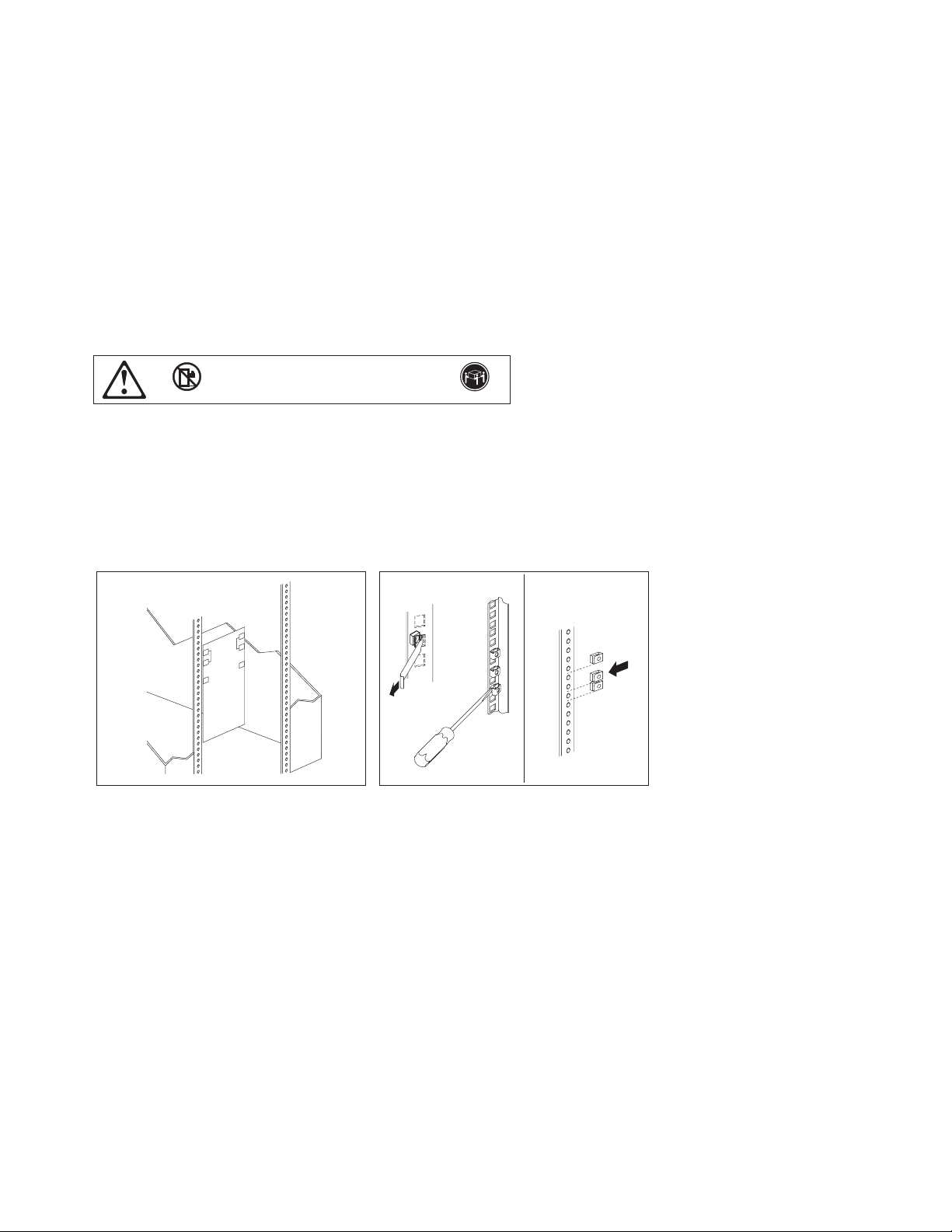
Rack Mounting Instructions
• Review the documentation that comes with your rack enclosure.
• Maintain 15 cm (6 in.) of clearance around your appliance for air circulation.
• Ensure the room air temperature is below 35°C(95°F).
• Plan the installation working from the bottom of the rack up.
• Remove the rack doors and the side panels during the installation, if necessary.
• Position the template to the rack so that the edges of the template do not
overlap any other devices to be installed.
• Connect all power cords on the and on other devices to properly wired
and grounded electrical outlets.
• Take precautions to prevent the rack from overloading the power outlets
when you install multiple devices in a rack.
The following is a list of items shipped in your rack installation kit. If any
items are missing or damaged, contact your place of purchase.
• Cable-management assembly
• Cable straps (7)
• Cable ties (10)
• Cage nuts (12)
appliance
appliance
• Do not place any object weighing more than 82kg
(180 lb) on top of rack-mounted devices.
• Use safe practices when lifting.
• Clip nuts (12)
• Screw packages (2)
• Slide rails (2)
32 kg (70.5 lb)82 kg (180 lb)
1
T
e
m
p
l
a
t
e
Use the attached stickers to mark the holes on
the front and the rear of the rack in the
locations indicated by the arrows on the
template.
Figure 2. Rack mounting instructions
2
Cage
nuts
Cage
nuts
Use a screwdriver or the cage-nut-insertion
tool to insert the cage nuts, or s
as required for your rack, into all the
nuts,
marked holes.
Clip
nuts
lide on the clip
8 IBM TotalStorage
™
Network Attached Storage 200 Installation Guide
Page 23
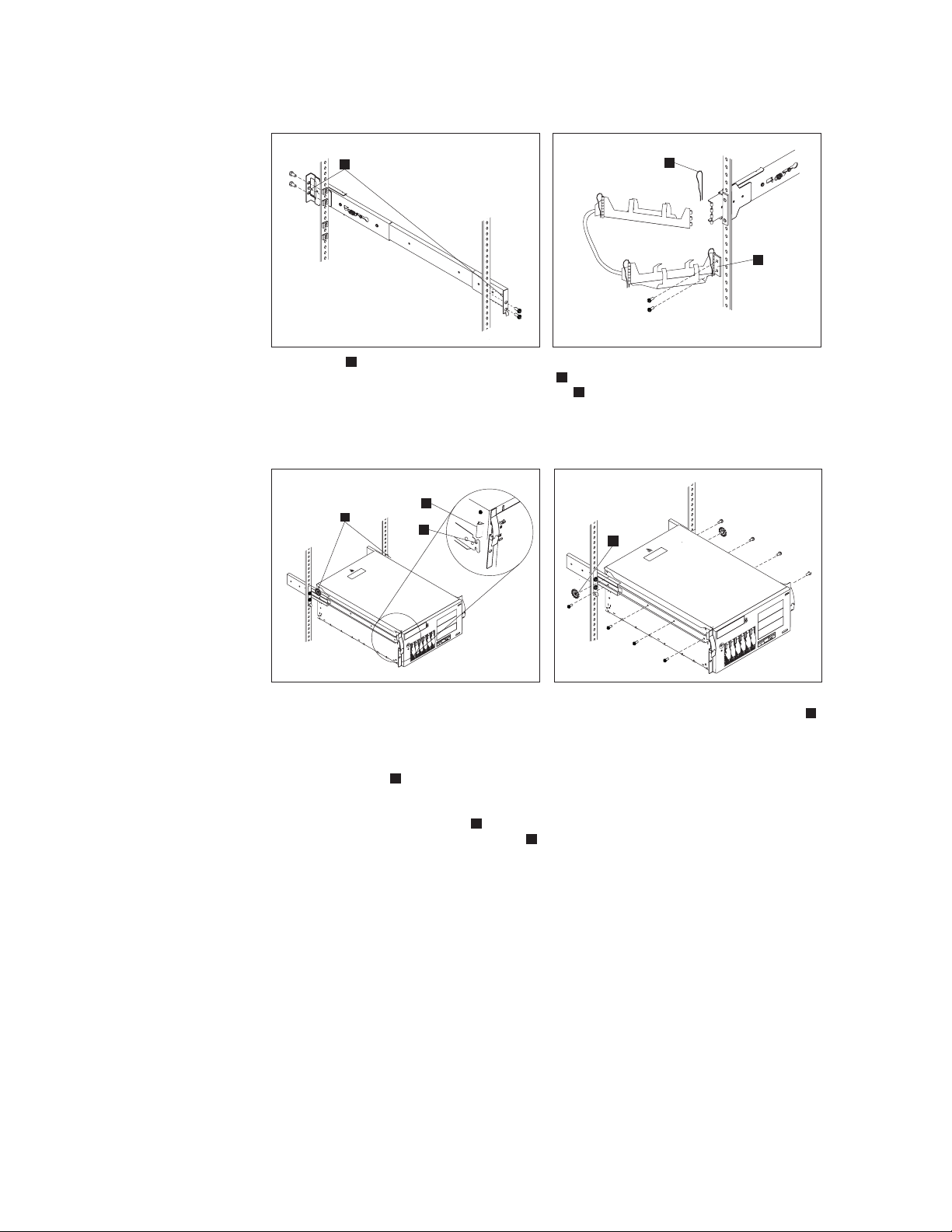
3
A
4
B
A
Use the pins on the slide rail to align the
slide rail to the rack. Use the M6 screws to
bolt the slide rail to the rack (left front of rack
shown here). Repeat this step for the other
slide rail.
5
Caution: To avoid injury, do not place your
fingers around the rack-support wheels when
lowering the onto the rails.appliance
Fully extend the slide rails out of the rack. Lift
the above the rails; then, rest the
appliance
rack-support wheels located on the rear of the
appliance
the onto the slide rails.
appliance
Note:
front of the fit securely on the tabs
located on the front of the slide rails.
A
A
on the slide rails. Lower the front of
Be sure the bracket notches on the
appliance
B
C
A
B
C
Use the M6 screws to attach the hinge bracket
A
to the rear of the rack. Then, use the hinge
B
pin to attach the cable-management
assembly to the slide rail. (Right rear of rack
shown here).
6
A
Use the M4 screws to secure the appliance to
the rails. Unscrew the rack-support wheels
and store them in a safe place.
A
Chapter 2. Installation procedures 9
Page 24
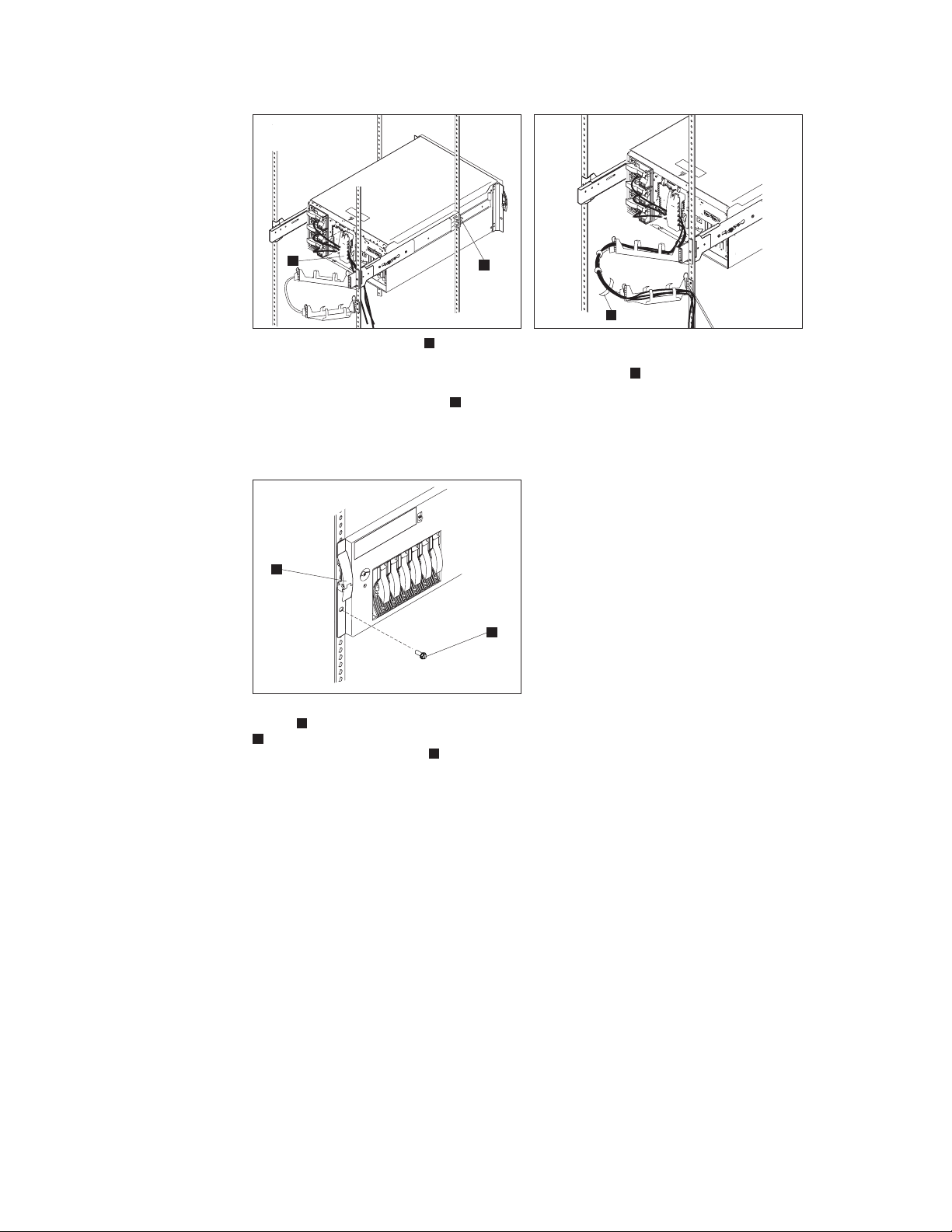
87
B
Press in on the safety latches and slide the
appliance
halfway into the rack. Attach the
A
A
power, keyboard, mouse, and monitor cables
(if required) to the and route them
through the cable restraint bracket . Then,
appliance
B
attach all other required cables to the
appliance.
9
A
B
Slide the into the rack until the release
latches snap shut. Then, insert the M6 screws
B
Note:
you are moving the rack or the rack is in a
vibration-prone area.
appliance
A
through the release-latch-bracket assembly.
Inserting the M6 screws is optional, unless
B
A
Route all the cables through the cablemanagement assembly as shown. Then, use
the cable straps or the cable ties to secure
A
the cables to the cable-management assembly.
10 IBM TotalStorage
™
Network Attached Storage 200 Installation Guide
Page 25
Installing optional features
The appliance has several optional features available.
Installing a 5194-EXU storage unit
The Model 225 includes the option of installing up to three additional 5194-EXU
storage units, or Model EXUs. The internal hot-swap SCSI disks are connected
internally to Channel 1 for both the ServeRAID-4H and ServeRAID-4L adapters. You
cannot attach a 5194-EXU storage unit to a Model 200 because ServeRAID-4L has
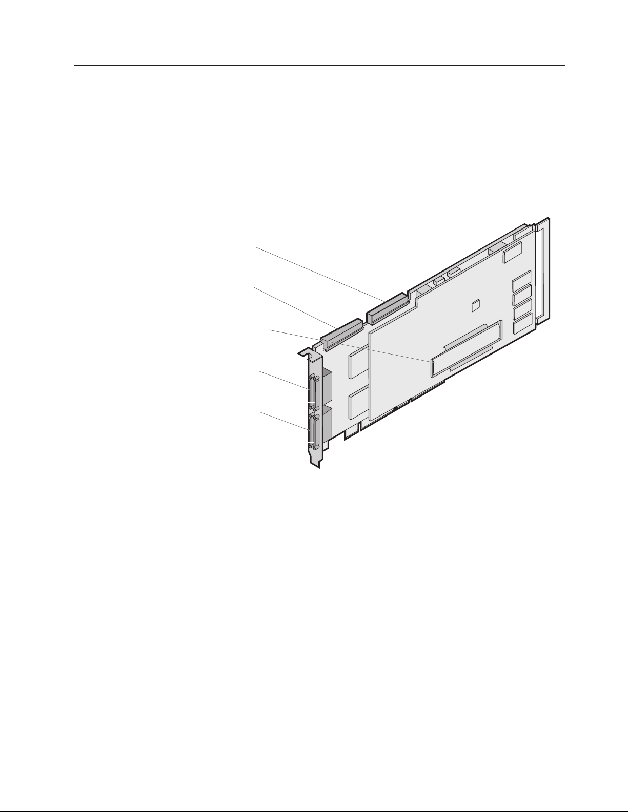
only one channel connector.
Internal Channel 2
Internal Channel 1
Battery-backup cache
External Channel 1
External Channel 2
External Channel 3
External Channel 4
Figure 3. ServeRAID-4H channel connector locations
Important: When adding 5194-EXU storage units to the Model 225, connect the
first additional storage unit to Channel 2, the second to Channel 3, and
so forth.
Notes:
1. The ServeRAID-4L and ServeRAID-4H adapters do not support configurations
that use both the internal and external connectors on the same channel
concurrently. For example, you cannot use both external Channel 1 and internal
Channel 1.
2. The battery-backup cache protects the data stored in the ServeRAID cache
memory during a power outage or failure when using the write-back mode.
3. The ServeRAID-4H controller uses the module (part number 38L3386)
containing a lithium battery.
Chapter 2. Installation procedures 11
Page 26

Statement 2
CAUTION:
When replacing the lithium battery, use only IBM Part Number 33F8354 or an
equivalent type battery recommended by the manufacturer. If your system has
a module containing a lithium battery, replace it only with the same module
type made by the same manufacturer. The battery contains lithium and can
explode if not properly used, handled, or disposed of.
Do not:
v Throw or immerse into water
v Heat to more than 100°C (212°F)
v Repair or disassemble
Dispose of the battery as required by local ordinances or regulations.
Note: For translations of the safety notices that are included in this guide, refer to
Safety Information.
To connect 5194-EXU storage units to an external channel connector on the
ServeRAID-4H controller:
1. Connect one end of a 68-pin very high density connector interface (VHDCI)
SCSI cable to an external channel connector on the ServeRAID-4H adapter.
Note: See Figure 3 on page 11 for the channel connector locations.
2. Connect the other end of the SCSI cable to the 5194-EXU storage unit. For
detailed installation and cabling instructions for the 5194-EXU storage unit, refer
to the IBM TotalStorage Network Attached Storage 5194-EXU Storage Unit
Installation and User’s Guide.
Installing a hot-swap hard drive
You can install up to three hot-swap drives in the Model 200. (The Model 225
already has the maximum number of hot-swap drives allowed without adding a
5194-EXU storage unit.)
Each hot-swap drive that you plan to install must have a hot-swap-drive tray
attached. The drive must have a single connector attachment (SCA) connector.
Hot-swap-drive trays come with the hot-swap drives.
v Models 200 and 225 support six slim (1-inch) 3.5-inch hot-swap hard disk drives
in the hot-swap bays. The Model EXU supports 14 slim (1-inch) 3.5-inch
hot-swap hard disk drives.
v The hot-swap bays connect to the planar. The planar is the printed circuit board
behind the bay.
v The planar controls the SCSI IDs for the hot swap drives.
12 IBM TotalStorage
™
Network Attached Storage 200 Installation Guide
Page 27
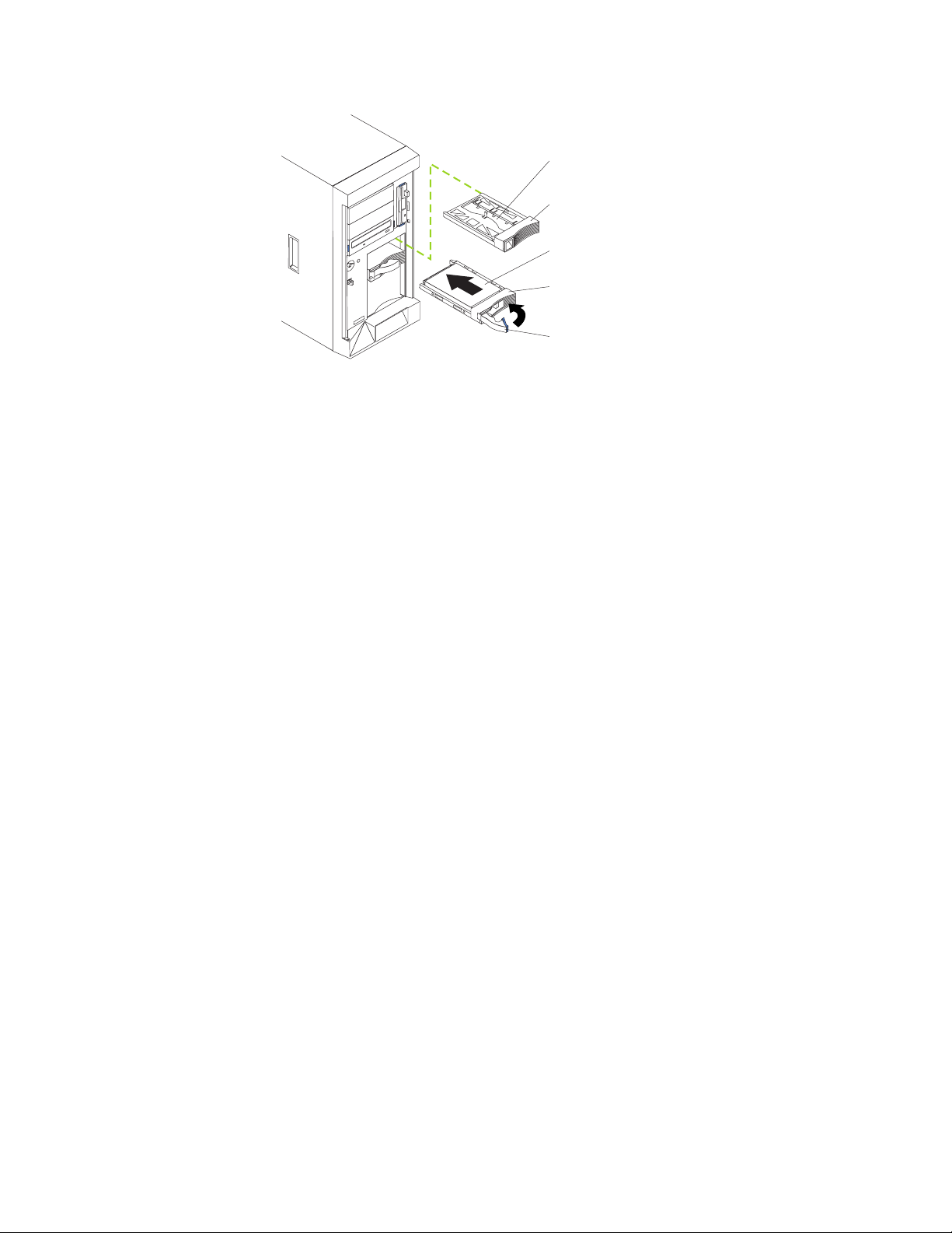
Slim filler
Filler panel
Hard disk drive
Drive tray
Drive tray handle
(in open position)
Figure 4. Installing a hot-swap hard drive
Attention:
v To maintain proper system cooling, do not operate the appliance for more than
two minutes without either a drive or a filler panel installed for each bay.
v You do not need to switch off the Models 200 and 225 or remove covers to install
or replace hot-swap power supplies or hot-swap hard drives.
v Back up all important data before you make changes to hard drives.
v When you handle electrostatic discharge-sensitive devices (ESDs), take
precautions to avoid damage from static electricity. For details on handling these
devices, refer to “Handling electrostatic discharge-sensitive devices” on page 76.
To install a hard disk drive in a hot-swap drive bay:
1. Review the safety precautions in “Safety precautions” on page ix.
2. Remove the filler panel from one of the empty hot-swap bays by inserting your
finger into the depression at the left side of the filler panel and pulling it away
from the appliance.
3. Install the hard disk drive in the hot-swap bay:
a. Ensure the tray handle is open (that is, perpendicular to the drive).
b. Align the rails on the drive assembly with the guide rails in the drive bay.
c. Gently push the drive assembly into the bay until the drive connects to the
planar.
d. Push the tray handle toward the closed position until it locks the drive in
place.
4. Check the hard disk drive status indicators to verify that the hard disk drives are
operating properly :
v When the amber LED is on continuously, the drive has failed.
v When the green LED flashes slowly (one flash per second), the drive is being
rebuilt.
v When the green LED flashes rapidly (three flashes per second), the controller
is identifying the drive.
Chapter 2. Installation procedures 13
Page 28

Installing memory modules (DIMMs)
You can install additional memory modules to the Model 200, which includes one
256-MB DIMM.
This section describes how to replace a memory module. It consists of four steps:
1. Prepare to install the memory module (see “Preparing to install a memory
module”).
2. Remove the cover (see “Removing the cover” on page 15).
3. Install the memory module (see “Adding the memory module” on page 17).
4. Replace the cover (see “Replacing the cover” on page 19).
Preparing to install a memory module
Read these notes before installing a memory module.
Note:
v Become familiar with the safety and handling guidelines specified under
“Handling electrostatic discharge-sensitive devices” on page 76.
v The blue color on components and labels inside your Models 200 and 225
identifies touch points where a component can be gripped, a latch moved,
and so on. The only exception to this is the power supplies, which are
orange.
v Make sure that you have an adequate number of properly grounded
electrical outlets for Models 200 and 225 and any other options that you
intend to install.
v Have a small, flat-blade screwdriver available.
v Before you begin installing components, read the safety information found
in “Translated safety notices” on page 77.
v For translations of the safety notices that are included in this guide, refer
to Safety Information.
14 IBM TotalStorage
System reliability considerations: To help ensure proper cooling and system
reliability, make sure that:
v Each of the drive bays has either a drive or a filler panel installed.
v The cover is in place during normal operations, or is removed for no longer than
30 minutes while the appliance is operating.
Note: The front door (Model 200) can be removed permanently without affecting
system reliability.
v There is space around the appliance to allow the appliance cooling system to
work properly.
– For Model 200, leave about 127 mm (5 in.) of space around the front and rear
of the appliance.
– For Model 225, refer to the documentation that comes with the rack.
v A removed hot-swap drive is replaced within 2 minutes of removal.
v Cables for optional adapters are routed according to the instructions provided
with the adapters.
v A failed fan is replaced within 48 hours.
™
Network Attached Storage 200 Installation Guide
Page 29
Removing the cover
Removing the Model 200 cover:
Left-side cover
Cover
release
lever
Figure 5. Removing the cover of the Model 200
To remove the left-side cover of the Model 200:
1. Review the information in “Preparing to install a memory module” on page 14.
2. Switch off the appliance and all attached devices and disconnect all external
cables and power cords.
3. Slide the cover-release lever on the front of the appliance to release the cover;
then, slide the cover toward the rear of the appliance about 25 mm (1 in.). Move
the top edge of the cover out from the appliance; then, lift the cover off the
appliance. Set the cover aside.
Attention: For proper cooling and airflow, replace the cover before switching
on the appliance. Operating the appliance for extended periods of time (over 30
minutes) with the cover removed might damage appliance components.
Chapter 2. Installation procedures 15
Page 30
Removing the Model 225 cover:
Top cover
Right-side
latch
Cover release lever
Left-side latch
Figure 6. Removing the cover of the Model 225
To remove the appliance top cover:
1. Review the information in “Preparing to install a memory module” on page 14.
2. Switch OFF the appliance and all attached devices and disconnect all external
cables and power cords.
3. Release the left and right side latches and pull the appliance out of the rack
enclosure until both slide rails lock.
Note: When the appliance is in the locked position, you can reach the cables
on the back of the appliance.
4. Move the cover-release lever down while sliding the top cover toward the rear of
the appliance about 25 mm (1 in.). Lift the cover off the appliance and set the
cover aside.
Attention: For proper cooling and airflow, replace the cover before switching
on the appliance. Operating the appliance for extended periods of time (over 30
minutes) with the cover removed might damage appliance components.
16 IBM TotalStorage
™
Network Attached Storage 200 Installation Guide
Page 31

Adding the memory module
Read these notes before adding the memory module.
Note: The Model 200 supports additional 256-MB, 512-MB, and 1-GB DIMMs. The
Model 225 supports additional 512-MB DIMMs. Both models support a
maximum of 2-GB of memory.
To install a memory module (DIMM):
Attention: When you handle electrostatic discharge-sensitive devices (ESDs),
take precautions to avoid damage from static electricity. For details on handling
these devices, refer to “Handling electrostatic discharge-sensitive devices” on
page 76.
1. Review the safety precautions listed in Statement 1 and Statement 5 in
“Translated safety notices” on page 77.
2. Review the documentation that comes with your option.
3. Switch off the appliance and peripheral devices and disconnect all external
cables and power cords.
4. Remove the cover.
5. Touch the static-protective package containing the DIMM to any unpainted metal
surface on the appliance. Then, remove the DIMM from the package.
Note: To avoid breaking the retaining clips or damaging the DIMM connectors,
handle the clips gently.
Chapter 2. Installation procedures 17
Page 32

6. Install the DIMM:
a. Turn the DIMM so that the pins align correctly with the connector.
b. Insert the DIMM into the connector by pressing on one edge of the DIMM
and then on the other edge of the DIMM. Be sure to press straight into the
connector. Be sure that the retaining clips snap into the closed positions.
c. Make sure the retaining clips are in the closed position. If a gap exists
between the DIMM and the retaining clips, the DIMM has not been properly
installed. In this case, open the retaining clips and remove the DIMM; then,
reinsert the DIMM.
DIMM 2
DIMM 1
DIMM connector 4 (J18)
DIMM connector 3 (J19)
DIMM connector 2 (J21)
DIMM connector 1 (J23)
Figure 7. Installing a DIMM
7. Install additional DIMMs in the order specified in the documentation that comes
with your option. (See Figure 7 for memory connector locations.)
8. Continue with “Replacing the cover” on page 19.
18 IBM TotalStorage
™
Network Attached Storage 200 Installation Guide
Page 33

Replacing the cover
Replacing the Model 200 cover:
Slots
Left-side cover
Figure 8. Replacing the Model 200 cover
To replace the appliance left-side cover:
1. Align the cover with the left side of the appliance, about 25 mm (1 in.) from the
front of the appliance; place the bottom of the cover on the bottom rail of the
chassis.
2. Insert the tabs at the top of the cover into the slots at the top of the appliance.
3. Hold the cover against the appliance and slide the cover toward the front of the
appliance until the cover clicks into place.
4. Switch on the appliance.
5. The system displays a message indicating that the memory configuration has
changed. Start the Configuration/Setup Utility program and select Save
Settings.
6. Restart the appliance.
Chapter 2. Installation procedures 19
Page 34

Replacing the Model 225 cover:
Flange
Top cover
Flange
Side latches
Figure 9. Replacing the Model 225 cover
To replace the appliance top cover:
1. Align the top cover with the top of the appliance, about 25 mm (1 in.) from the
front of the appliance; the flanges on the left and right sides of the cover should
be on the outside of the appliance chassis.
2. Hold the cover against the appliance and slide the cover toward the front of the
appliance until the cover clicks into place.
3. Switch on the appliance.
4. The system displays a message indicating that the memory configuration has
changed. Start the Configuration/Setup Utility program and select Save
Settings.
5. Restart the appliance.
Cabling
20 IBM TotalStorage
For each of the three power supplies, connect one end of the power cord to the
power supply and the other end to an appropriate outlet. Connect one end of the
Gigabit Ethernet cable to the Gigabit Ethernet Adapter located in one of the
expansion slots (see Figure 10 on page 21) and the other to the system network.
Note: You may use a 10/100 Ethernet cable if your network does not support
Gigabit Ethernet.
When you cable the appliance, be sure to route the power and network cables
through the cable-restraint bracket on the rear of the appliance.
™
Network Attached Storage 200 Installation Guide
Page 35

Serial A
Keyboard
Service
Ethernet
Video
Figure 10. Cabling the appliance
Cable-restraint
bracket
ServeRAID
Gigabit Ethernet
Chapter 2. Installation procedures 21
Page 36

Additionally, for Model 225, be sure to thread the cables through the cable-restraint
bracket and then route the cables through the cable-management assembly on the
rack (see Figure 11).
Cable straps
Figure 11. Routing cables through cable-management assembly
22 IBM TotalStorage
™
Network Attached Storage 200 Installation Guide
Page 37

Starting the appliance
Complete the installation by switching on the appliance and running the power-on
diagnostics. Each time the appliance is switched on, it runs a self-testing program
to ensure that it is running correctly. See Figure 12 for the locations of the
Information LED, System Error LED, POST Complete (OK) LED, and Power-on
LED.
Note: Depending on the system status, other LEDs may be on.
34
OK
100
MB
Figure 12. Locations of the Information LED, System Error LED, POST Complete (OK) LED,
and Power-on LED
1 Information LED
2 System Error LED
LINK
OK
TX
RX
3 Power-on LED
4 POST Complete (OK) LED
If a problem is detected during the diagnostics, refer to the IBM TotalStorage
Network Attached Storage Models 200 and 225 Service Guide.
After you plug the power cord of the appliance into the power supply and an
electrical outlet, start the appliance by pressing the power button on the front of the
appliance.
Note: After you plug the power cord of the appliance into an electrical outlet, wait
approximately 20 seconds before pressing the power button. During this
time, the system-management processor is initializing and the power button
does not respond.
Attention: The operating system undergoes a series of initialization operations
upon start up. The first time you start the appliance, a series of configuration and
system preparation programs that finish configuring the NOS are run automatically.
These programs must finish running before you use any included applications to
connect to or configure your appliance. Wait at least 5 minutes to connect to or
configure the appliance after the initial system start.
Chapter 2. Installation procedures 23
Page 38

Note: This notice applies only to the first time the appliance is started.
When switching off the appliance, be aware of the following safety precautions:
v Statement 5
CAUTION:
The power control button on the device and the power switch on the power
supply do not turn off the electrical current supplied to the device. The device
also might have more than one power cord. To remove all electrical current
from the device, ensure that all power cords are disconnected from the power
source.
2
1
Note: For translations of this safety notice, refer to Safety Information.
You can switch off the appliance as follows:
v Press the power button on the front of the appliance. This starts an orderly
shutdown of the operating system, if this feature is supported by your operating
system, and places the appliance in standby mode.
Note: After switching off the appliance, wait at least 5 seconds before you press
the power button to switch on the appliance again.
v Press and hold the power button for more than 4 seconds to cause an immediate
shutdown of the appliance and place the appliance in standby mode. You can
use this feature if the operating system ceases to function.
v Disconnect the appliance power cords from the electrical outlets to shut off all
power to the appliance.
Note: Wait about 15 seconds after disconnecting the power cords for your
system to stop running. Watch for the Power-on LED on the operator
information panel to stop blinking.
24 IBM TotalStorage
™
Network Attached Storage 200 Installation Guide
Page 39

Performing initial configuration
Refer to the IBM TotalStorage Network Attached Storage Models 200 and 225
User’s Reference for software configuration and setup.
Chapter 2. Installation procedures 25
Page 40

26 IBM TotalStorage
™
Network Attached Storage 200 Installation Guide
Page 41

Chapter 3. Adding and replacing components
This chapter instructs you on how to add and replace components, informs you
about safety and system reliability, and shows you the location of the major
components.
Before you begin
Before you begin to install options in your Models 200 and 225, read the following
information:
v Become familiar with the safety and handling guidelines specified under
“Handling electrostatic discharge-sensitive devices” on page 76.
v You do not need to switch off the Models 200 and 225 or remove covers to install
or replace hot-swap power supplies or hot-swap hard drives.
v The blue color on components and labels inside your Models 200 and 225
identifies touch points where a component can be gripped, a latch moved, and so
on.
v Make sure that you have an adequate number of properly grounded electrical
outlets for Models 200 and 225 and any other options that you intend to install.
v Back up all important data before you make changes to hard drives.
v Have a small, flat-blade screwdriver available.
Safety information
Before you begin installing components, read the safety information found in
“Translated safety notices” on page 77. For translations of the safety notices that
are included in this guide, refer to Safety Information.
System reliability considerations
Adding options to the base configurations could increase power requirements
beyond the limit for redundancy. To ensure that redundancy is maintained, check
the status of the NON LED on the system board after you install any option.
To help ensure proper cooling and system reliability, make sure that:
v Each of the drive bays has either a drive or a filler panel installed.
v The cover is in place during normal operations, or is removed for no longer than
30 minutes while the appliance is operating.
Note: The front door (Model 200) can be removed permanently without affecting
system reliability.
v There is space around the appliance to allow the appliance cooling system to
work properly.
– For Model 200, leave about 127 mm (5 in.) of space around the front and rear
of the appliance.
– For Model 225, refer to the documentation that comes with the rack.
v A removed hot-swap drive is replaced within 2 minutes of removal.
v Cables for optional adapters are routed according to the instructions provided
with the adapters.
v A failed fan is replaced within 48 hours.
© Copyright IBM Corp. 2001 27
Page 42

Working inside an appliance while power is on
Your appliance is designed to operate safely while switched on with the cover
removed. Follow these guidelines when you work inside an appliance that is
switched on:
v Avoid loose-fitting clothing on your forearms. Button long-sleeved shirts before
working inside the appliance; do not wear cuff links while you are working inside
the appliance.
v Do not allow your necktie or scarf to hang inside the appliance.
v Remove jewelry, such as bracelets, rings, necklaces, and loose-fitting wrist
watches.
v Remove items from your shirt pocket (such as pens or pencils) that could fall into
the appliance as you lean over it.
v Take care to avoid dropping any metallic objects, such as paper clips, hair pins,
or screws, into the appliance.
28 IBM TotalStorage
™
Network Attached Storage 200 Installation Guide
Page 43

Major components of the Network Attached Storage 200
Figure 13 shows the locations of major components in your appliance.
Note: The illustrations in this document might differ slightly from your hardware.
Microprocessor
Adapter
retention
bracket
Adapter
support
bracket
Fan
Power supply
Terminator card
Memory module
Figure 13. Locations of major components
Fan (blower)
Chapter 3. Adding and replacing components 29
Page 44

System board
Figure 14 identifies system-board connectors for user-installable options.
PCI slot 5
64-bit
33 MHz (J44)
Battery
PCI slot 4
64-bit
33 MHz (J39)
PCI slot 3
64-bit
33 MHz (J34)
PCI slot 2
32-bit
33 MHz (J32)
PCI slot 1
32-bit
33 MHz (J27)
DIMM 1 (J23)
DIMM 2 (J21)
DIMM 3 (J19)
DIMM 4 (J18)
Microprocessor 2 (U17)
Microprocessor 1 (U3)
Voltage regulator
module (VRM2) (U29)
Figure 14. System-board options connectors
30 IBM TotalStorage
™
Network Attached Storage 200 Installation Guide
Page 45

Figure 15 identifies system-board connectors for internal cables.
Fan 3 (J35)
Main power (J4)
Power-signal (J51)
DASD (SCSI) system
management (J5)
Power-system management
and signal (J12)
Diskette (J26)
IDE (J31)
On-Off/Reset
panel (J38)
Fan 2 (J60)
Figure 15. System-board internal cable connectors
Fan 1 (unused) (J59)
Operator information
panel (J50)
Chapter 3. Adding and replacing components 31
Page 46

Figure 16 identifies system-board connectors for external devices.
Video/Advanced
System Management
Processor port (J13)
Ethernet port (J9)
Keyboard/mouse port (J6)
Serial ports (J3)
Figure 16. System board external port connectors
32 IBM TotalStorage
™
Network Attached Storage 200 Installation Guide
Page 47

Figure 17 identifies the switches and jumpers on the system board.
System board jumper blocks
Boot block
jumper (J37)
System board
switch block (SW1)
Figure 17. System board switches and jumpers
Diagnostics
panel
Any jumper blocks on the system board that are not shown in the illustration are
reserved. For normal operation of the system, no jumpers should be installed on
any of the jumper blocks. See Figure 17 for information about the boot block
jumper.
System board switch block
The switch block contains microswitches1-8.Switch 8 is at the top of the switch
block and switch 1 is at the bottom. The Off position for each switch is the side
nearer the diagnostics panel.
Table 4 describes the function for each switch.
Table 4. Switches 1 - 8
Switch
number
8 Bypass power-on password. The default setting is Off.
7 Reserved. The default setting is Off.
6 Clock frequency selection. The default setting is Off.
Switch
description
When toggled to the On position and back to Off, clears the power-on
password, if one is set.
When On, sets the host bus speed to 100 MHz. When Off, the host bus
speed is 133 MHz.
Chapter 3. Adding and replacing components 33
Page 48

Table 4. Switches 1 - 8 (continued)
Switch
number
Switch
description
5 Power-on override. The default setting is Off (disabled).
When On, overrides the power-on switch and forces power-on mode. The
system will always boot without the use of the power-on switch.
4 Reserved.
3 Reserved.
2 Reserved.
1 Reserved.
Figure 18 identifies system-board LEDs. You might need to refer to this figure when
troubleshooting a problem.
DIMM 4
failure (CR20)
DIMM 3
failure (CR18)
DIMM 2
failure (CR28)
DIMM 1
failure (CR21)
Microprocessor 2
failure (CR7)
Microprocessor 1
failure (CR1)
Voltage regulator module
(VRM2) failure (CR16)
Integrated voltage regulator
(VRM1) failure (CR4)
Power-on
(CR56)
Diagnostics panel
Advanced System
Management Processor
error (CR70)
Figure 18. System board LED locations
Note: The power-on indicator (CR56) is on when system power is present in the
appliance. When this LED flashes, the appliance is in standby mode (the
system power supply is turned off and current is present).
Diagnostics panel LEDs:
PS1 Power supply 1 failure.
PS2 Power supply 2 failure.
PS3 Power supply 3 failure.
NON Non-redundant power.
OVER Overspec. The system has exceeded the power capabilities of the installed
power supply units.
NMI Non-maskable-interrupt occurred.
TEMP System temperature exceeded maximum rating.
FAN A fan failed or is operating slowly.
MEM Memory failure. One or more memory DIMMS have failed.
CPU Microprocessor failure. One or both microprocessors have failed.
PCI A Error on PCI channel A or system board.
34 IBM TotalStorage
™
Network Attached Storage 200 Installation Guide
Page 49

Note: PCI bus A is often referred to as PCI bus 0.
PCI B Error on PCI channel B or system board.
Note: PCI bus B is often referred to as PCI bus 1.
VRM Error on voltage regulator module or on integrated voltage regulator.
DASD1
A hot-swap disk drive, backplane, or other part of SCSI channel A has
failed.
DASD2
A SCSI device on SCSI channel B has failed.
Appliance controls and indicators
Figure 19, Figure 20 on page 36, Figure 21 on page 37, and Figure 22 on page 38
illustrate the various controls and indicators on the appliance models.
Note: The Model 200 is also known as the tower model. The Model 225 is also
known as the rack model.
Figure 19. Model 200 front view
1 Operator Information panel
2 Hard Drive Status LED
3 Hard Drive Activity LED
4 Serial Number
5 Cover Release Latch
6 Reset Button
7 Power Control Button
8 Power Control Button Shield (if installed)
Chapter 3. Adding and replacing components 35
Page 50

Figure 20. Model 225 front view
1 Cover-release latch
2 Serial Number
3 Hard Drive Status LED
4 Hard Drive Activity LED
5 Reset Button
6 Power Control Button
7 Power Control Button Shield (if installed)
8 Operator Information panel
Reset Button Press this button to reset the appliance and run the POST.
Attention: Press this button only when the appliance is hung.
Pressing this button when the appliance is booting up or operating
may make the appliance non-operational or corrupt the drives.
Operator Information panel
The LEDs on this panel give status information for your appliance.
See “Operator information panel” on page 39 for more information.
Hard Drive Status LED
Each of the hot-swap drives has a Hard Drive Status LED. When
this amber LED is on continuously, the drive has failed. When the
LED flashes slowly (one flash per second), the drive is being
rebuilt. When the LED flashes rapidly (three flashes per second),
the controller is identifying the drive.
36 IBM TotalStorage
Hard Drive Activity LED
Each of the hot-swap drives has a Hard Drive Activity LED. When
this green LED is flashing, the controller is accessing the drive.
™
Network Attached Storage 200 Installation Guide
Page 51

3
4
5
6
7
8
Figure 21. Model 200 rear view
1 AC Power LED
This LED provides status information about the power supply. During
normal operation, both the AC and DC Power LEDs are on.
2 DC Power LED
This LED provides status information about the power supply. During
normal operation, both the AC and DC Power LEDs are on.
3 Serial Port A
4 Mouse
5 Keyboard
6 Ethernet port
7 Video
8 Management
Chapter 3. Adding and replacing components 37
Page 52

4
3
Figure 22. Model 225 rear view
5
6
1 AC Power LED
This LED provides status information about the power supply. During
normal operation, both the AC and DC Power LEDs are on.
2 DC Power LED
This LED provides status information about the power supply. During
normal operation, both the AC and DC Power LEDs are on.
3 Serial Port A
4 Mouse
5 Keyboard
6 Ethernet port
7 Video
8 Management
8
7
38 IBM TotalStorage
™
Network Attached Storage 200 Installation Guide
Page 53

Operator information panel
The operator information panel on the front of the appliance contains status LEDs.
OK
TX
LINK
100
OK
MB
Figure 23. Operator information panel
1 Information LED
2 System Error LED
3 Ethernet Transmit/Receive Activity (TX/RX) LED
4 Ethernet Link Status (LINK OK) LED
5 Ethernet Speed (100 MB) LED
6 Power-on LED
7 POST Complete (OK) LED
RX
8 SCSI Hard Drive In-use LED
Information LED
This amber LED is on when the information log contains information about
certain conditions in your appliance that might affect performance. For
example, the LED is on if your appliance does not have redundant power. A
LED on the diagnostic panel on the system board will also be on.
System Error LED
This amber LED is on when a system error occurs. A LED on the diagnostic
panel on the system board will also be on to further isolate the error.
Ethernet Transmit/Receive Activity LED
This green LED is on when there is transmit or receive activity to or from
the appliance on the Service Ethernet port.
Ethernet Link Status LED
This green LED is on when there is an active connection on the Service
Ethernet port.
Ethernet Speed LED
This green LED is on when the Service Ethernet LAN speed is 100 Mbps.
Power-on LED
This green LED is on when system power is present in the appliance.
When this LED flashes, the appliance is in standby mode (the system
power supply is turned off and AC current is present). If this LED is not on,
the power cord is not connected, the power supply has failed, or this LED
has failed.
Chapter 3. Adding and replacing components 39
Page 54

POST Complete LED
This green LED is on when the appliance completes the POST without any
errors.
SCSI Hard Drive In-use LED
This green LED is on when there is activity on a hard drive.
Adding or removing internal hardware components
This section describes how to add or remove internal hardware components.
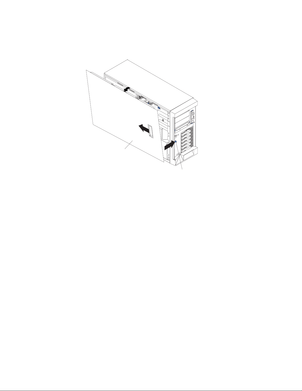
Removing the cover (Model 200)
The following sections describe how to remove the cover, the door (for the Model
200), and the bezel.
Left-side cover
Cover
release
lever
Figure 24. Removing the cover of the Model 200
To remove the left-side cover of the Model 200:
1. Review the information in “Before you begin” on page 27.
2. If you are planning to install or remove any part other than a hot-swap hard disk
drive or hot-swap power supply, switch off the appliance and all attached
devices and disconnect all external cables and power cords.
3. Slide the cover-release lever on the front of the appliance to release the cover;
then, slide the cover toward the rear of the appliance about 25 mm (1 in.). Move
the top edge of the cover out from the appliance; then, lift the cover off the
appliance. Set the cover aside.
Attention: For proper cooling and airflow, replace the cover before switching
on the appliance. Operating the appliance for extended periods of time (over 30
minutes) with the cover removed might damage appliance components.
40 IBM TotalStorage
™
Network Attached Storage 200 Installation Guide
Page 55

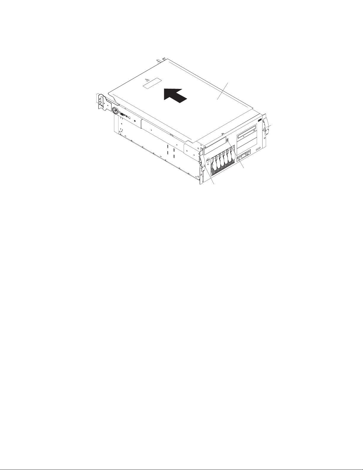
Removing the cover (Model 225)
Figure 25. Removing the cover of the Model 225
To remove the appliance top cover:
1. Review the information in “Before you begin” on page 27.
2. If you are planning to install or remove any part other than a hot-swap hard disk
drive or hot-swap power supply, switch OFF the appliance and all attached
devices and disconnect all external cables and power cords.
3. Release the left and right side latches and pull the appliance out of the rack
enclosure until both slide rails lock.
Top cover
Right-side
latch
Cover release lever
Left-side latch
Note: When the appliance is in the locked position, you can reach the cables
on the back of the appliance.
4. Move the cover-release lever down while sliding the top cover toward the rear of
the appliance about 25 mm (1 in.). Lift the cover off the appliance and set the
cover aside.
Attention: For proper cooling and airflow, replace the cover before switching
on the appliance. Operating the appliance for extended periods of time (over 30
minutes) with the cover removed might damage appliance components.
Chapter 3. Adding and replacing components 41
Page 56

Removing the door and bezel (Model 200)
Bezel-release lever
Figure 26. Removing the appliance door of the Model 200
To remove the appliance door:
1. Unlock and open the appliance door.
2. Locate the flange on the top edge of the door.
3. Press down on the flange while pressing out on the door; then, lift the appliance
door up and off the hinge. Set the door aside in a safe place.
Door
Flange
To remove the bezel:
1. Move the blue bezel-release lever, following the curve of the lever opening.
2. Lift the bezel tabs out of the slots and pull the bezel away from the appliance
front. Store the bezel in a safe place.
42 IBM TotalStorage
™
Network Attached Storage 200 Installation Guide
Page 57

Removing the bezel (Model 225)
Bezel-release lever
Bezel
Figure 27. Removing the bezel of the Model 225
To remove the bezel:
1. Move the blue bezel-release lever, following the curve of the lever opening.
2. Lift the bezel tabs out of the slots and pull the bezel away from the appliance
front. Store the bezel in a safe place.
Installing internal drives
You can install a tape drive to store more data. You can see a list of supported tape
drives at www.storage.ibm.com.
Installing internal drive bays
Internal hard drives are installed in bays. The drive bays of the Network Attached
Storage 200 are in the front of the appliance, as shown in the following illustrations.
Attention: If you are going to install additional hard drives in the non-hot-swap
drive bays, you must install the power supply backplane option and additional
power supplies.
Chapter 3. Adding and replacing components 43
Page 58

Model 200:
Non-hot-swap
bay A
Non-hot-swap
bay B
Non-hot-swap
bay C
Hot-swap bays
Non-hot-swap
bay D
SCSI ID 0
Hard disk
activity light
Hard disk
status light
SCSI ID 2
SCSI ID 3
SCSI ID 4
SCSI ID 8
SCSI ID 9
Figure 28. Installing internal drive bays for the Model 200
Note: The SCSI IDs for the slim-high and half-high hot-swap hard drives are on a
label on the bezel, immediately adjacent to the hot-swap hard drive bays.
Model 225:
SCSI ID 0
SCSI ID 1
SCSI ID 4
SCSI ID 3
Hot-swap bays
SCSI ID 5
SCSI ID 9
Non-hot-swap
bay A
Non-hot-swap
bay B
Non-hot-swap
bay C
Non-hot-swap
bay D
Hard disk
activity light
Hard disk
status light
44 IBM TotalStorage
Figure 29. Installing internal drive bays for the Model 225
Installing and replacing hot-swap hard drives
Your appliance contains hardware that lets you continue to operate your system
while a hard drive is removed or installed. These hard drives are known as
hot-swappable hard drives. They are also referred to as hot-swap hard drives.
™
Network Attached Storage 200 Installation Guide
Page 59

Each hot-swap hard drive that you plan to install must have a hot-swap hard drive
tray attached. The hard drive must have a single connector attachment (SCA)
connector. Hot-swap hard drive trays come with the hot-swap drives.
v Your appliance supports up to six slim 25-mm (1-in.) hot-swap hard drives in the
hot-swap bays.
v The hot-swap hard drive bays connect to a SCSI backplane. This backplane is
the printed circuit board behind the bay.
v The backplane controls the SCSI IDs for the hot-swap hard drives.
Installing a hot-swap hard drive:
Slim filler
Filler panel
Hard disk drive
Drive tray
Drive tray handle
(in open position)
Figure 30. Installing a hot-swap drive
To install a drive in a hot-swap hard drive bay:
Attention:
v To maintain proper system cooling, do not operate the appliance for more than
two minutes without either a hard drive or a filler panel installed for each bay.
Therefore, if you are replacing a defective hot-swap drive, either leave the
defective drive in place or put in a filler panel until you have a replacement drive.
v When you handle electrostatic discharge-sensitive devices (ESDs), take
precautions to avoid damage from static electricity. For details on handling these
devices, refer to “Handling electrostatic discharge-sensitive devices” on page 76.
1. Remove the filler panel from one of the empty hot-swap drive bays by inserting
your finger into the depression at the left side of the filler panel and pulling it
away from the appliance.
2. Install the hard drive in the hot-swap drive bay:
a. Ensure the tray handle is open (that is, perpendicular to the hard drive).
b. Align the rails on the hard drive assembly with the guide rails in the drive
bay.
c. Gently push the hard drive assembly into the drive bay until the hard drive
connects to the backplane.
d. Push the tray handle toward the closed position until it locks the hard drive
in place.
3. Check the hard drive status indicators to verify that the hard drives are
operating properly (the Hard Drive Status LED is immediately to the right of the
hard disk drive).
v When the amber LED is on continuously, the hard drive has failed.
Chapter 3. Adding and replacing components 45
Page 60

v When the green LED flashes slowly (one flash per second), the hard drive is
being rebuilt.
v When the green LED flashes rapidly (three flashes per second), the controller
is identifying the hard drive.
4. Refer to the Network Attached Storage 200 User’s Reference for information
about using the ServeRAID utility to configure the hot-swap drive.
Replacing a hot-swap hard drive: You do not have to switch off the appliance to
remove or install the hot-swap hard drives.
Attention:
1. Before you replace a hot-swap hard drive, check the Hard Drive Status LED on
the front of the drive to see if the drive is defective (if the drive is defective, the
LED will be amber). If you partially or completely remove a good drive instead
of a defective one, you might lose valuable data.
This situation is especially relevant because your appliance has a RAID adapter
installed. The RAID adapter can rebuild the data that you need, provided that
certain conditions are met.
2. Before you remove a hot-swap hard drive that is not defective, back up all
important data.
3. To avoid damage to a hard drive, pull on the release lever to disengage the
hard drive connector from the backplane at the back of the drive bay, wait
approximately 30 seconds to allow the hard drive to spin down, and then
completely remove it from the bay.
Refer to Figure 31 while you perform the steps in this procedure.
Slim filler
Filler panel
Hard disk drive
Drive tray
Drive tray handle
(in open position)
Figure 31. Replacing a drive in a hot-swap drive bay in the Model 200
To replace a drive in a hot-swap drive bay:
1. Before you begin, read the documentation that comes with your hard drive.
2. If your appliance is a Model 200, unlock and open the appliance door.
Attention: To maintain proper system cooling, do not operate the appliance
for more than two minutes without either a hard drive or a filler panel installed
for each drive bay.
3. Locate the defective hard drive (look for an amber Hard Drive Status LED on
the front of the drive).
46 IBM TotalStorage
™
Network Attached Storage 200 Installation Guide
Page 61

4. Remove the defective hard drive: move the handle on the hard drive to the
open position (perpendicular to the hard drive) and pull the hot-swap hard drive
assembly from the drive bay.
5. Install the replacement hard drive in the hot-swap drive bay:
a. Ensure the tray handle is open (that is, perpendicular to the hard drive).
b. Align the rails on the hard drive assembly with the guide rails in the drive
bay.
c. Gently push the hard drive assembly into the drive bay until the hard drive
connects to the backplane.
d. Push the tray handle toward the closed position until it locks the hard drive
in place.
6. Check the hard drive status indicators to verify that the hard drive is installed
properly (the Hard Drive Status LED is located to the immediate right of the
hard disk drive).
v When the amber LED is on continuously, the hard drive has failed.
v When the green LED flashes slowly (one flash per second), the hard drive is
being rebuilt.
v When the green LED flashes rapidly (three flashes per second), the controller
is identifying the hard drive.
7. If your appliance is a Model 200, close and lock the appliance door.
Chapter 3. Adding and replacing components 47
Page 62

Replacing hot-swap power supplies
Your appliance comes with three hot-swap power supplies, installed in bays 1, 2,
and 3. The third power supply provides additional redundancy. Each power supply
has two status indicators; see the following illustration for information about the
status indicators and power supply bay locations.
Power supply 1 Power supply 2 Power supply 3
DC power
LED
AC power
LED
Figure 32. Replacing a hot-swap power supply
Power Supply 1
LED PS1 on the system board diagnostics panel refers to this power
supply. See Figure 18 on page 34 for more information about the
diagnostics panel.
Power Supply 2
LED PS2 on the system board diagnostics panel refers to this power
supply. See Figure 18 on page 34 for more information about the
diagnostics panel.
Power Supply 3
LED PS3 on the system board diagnostics panel refers to this power
supply. See Figure 18 on page 34 for more information about the
diagnostics panel.
AC Power LED
This LED provides status information about the power supply. During
normal operation, both the AC and DC Power LEDs are on. Refer to the
Power Supply LEDs section in the IBM TotalStorage IP Storage 200i
Administrator’s Guide for more information.
DC Power LED
This LED provides status information about the power supply. During
normal operation, both the AC and DC Power LEDs are on. Refer to the
Power Supply LEDs section in the IBM TotalStorage IP Storage 200i
Administrator’s Guide for more information.
48 IBM TotalStorage
™
Network Attached Storage 200 Installation Guide
Page 63

Removing a hot swap power supply
Statement 8
CAUTION:
Never remove the cover on a power supply or any part that has the following label
attached.
Hazardous voltage, current, and energy levels are present inside any component that has
this label attached. There are no serviceable parts inside these components. If you
suspect a problem with one of these parts, contact a service technician.
Note: For translations of this safety notice, refer to Safety Information.
Attention: If you remove a power supply while the system is running, when you
do not have power redundancy, your system will abruptly cease to function.
To remove a hot swap power supply
1. Check the LEDs on the power supplies to determine which power supply has
failed. If a power supply has failed, go to step 4 on page 50.
2. Remove the engine covers.
3. Check the LEDs on the diagnostics panel on the system board.
a. If the NON (non-redundant) LED is on, you do not have redundancy: switch
OFF the appliance and peripheral devices; then, continue with step 4 on
page 50.
Note: The Information LED on the operator information panel on the front of
the appliance also will be on. See “Appliance controls and indicators”
on page 35 for the location and contents of the operator information
panel.
b. If the NON LED is not lit, you have redundancy and do not need to switch
off the appliance. Continue with step 4 on page 50.
Chapter 3. Adding and replacing components 49
Page 64

Diagnostics panel
Figure 33. Removing a hot-swap power supply
4. Unplug the power cord from the power supply.
Statement 12
CAUTION:
The following label indicates a hot surface nearby.
Note: For translations of this safety notice, refer to Safety Information.
5. Remove the defective power supply.
6. Install a replacement power supply (see “Replacing a hot-swap power supply”
on page 51).
7. Plug the power cord for the power supply into the power cord connector.
8. Verify that the AC Power LED and DC Power LED are on, indicating that the
power supply is operating correctly.
9. If you switched the appliance off in step 3.3a on page 49, switch ON the
appliance and peripheral devices.
50 IBM TotalStorage
™
Network Attached Storage 200 Installation Guide
Page 65

Replacing a hot-swap power supply
After you replace a power supply, verify that the power-supply status indicators (AC
Power LED and DC Power LED) are on, indicating that the power supply is
operating properly.
Notes:
1. You do not need to switch off the power to the appliance to install hot-swap
power supplies.
2. When replacing a power supply, do not remove the power supply until you are
ready to install its replacement.
Figure 34. Installing a hot-swap power supply
To replace a hot-swap power supply:
1. Remove the power supply that you want to replace.
2. Install the replacement power supply in the bay:
a. Place the handle on the power supply in the open position (that is,
perpendicular to the power supply) and slide the power supply into the
chassis.
b. Gently close the handle to seat the power supply in the bay.
3. Plug the power cord for the power supply you just installed into the power cord
connector.
4. Route the power cord through the cable-restraint bracket.
5. Plug the power cord into a properly grounded electrical outlet.
6. Verify that the DC Power LED and AC Power LED on the power supply are on,
indicating that the power supply is operating correctly.
Chapter 3. Adding and replacing components 51
Page 66

Replacing the ServeRAID controller
This section provides illustrations of the SCSI channel connectors and cable
connectors for the ServeRAID-4H and ServeRAID-4L controllers.
ServeRAID-4H controller connector locations
The ServeRAID-4H controller has four independent SCSI channel connectors:
Channel 1, Channel 2, Channel 3, and Channel 4. Each of these SCSI channels
supports up to 15 physical devices.
Note: The battery-backup cache protects the data being stored in the ServeRAID
cache memory during a power outage or failure when using the write-back
mode.
Internal Channel 2
Internal Channel 1
Battery-backup cache
External Channel 1
External Channel 2
External Channel 3
External Channel 4
Figure 35. ServeRAID-4H controller
In the ServeRAID-4H controller, an internal SCSI device is attached to channel 1.
This means you cannot attach an external SCSI device to channel 1.
Note: The ServeRAID-4H controller uses the module (P/N 38L3386) containing a
lithium battery.
Statement 2
CAUTION:
When replacing the lithium battery, use only IBM Part Number 33F8354 or an
equivalent type battery recommended by the manufacturer. If your system has
a module containing a lithium battery, replace it only with the same module
type made by the same manufacturer. The battery contains lithium and can
explode if not properly used, handled, or disposed of.
52 IBM TotalStorage
™
Network Attached Storage 200 Installation Guide
Page 67

Do not:
v Throw or immerse into water
v Heat to more than 100°C (212°F)
v Repair or disassemble
Dispose of the battery as required by local ordinances or regulations.
Note: For translations of this safety notice, refer to Safety Information.
ServeRAID-4L controller connector locations
The ServeRAID-4L controller has one independent SCSI channel connector:
Channel 1. This SCSI channels supports up to 15 physical devices.
Internal Channel 1
External Channel 1
Figure 36. ServeRAID-4L controller
You cannot attach any external devices to the ServeRAID-4L controller.
Note: The ServeRAID-4L controller uses the module (P/N 38L3386) containing a
lithium battery.
Statement 2
CAUTION:
When replacing the lithium battery, use only IBM Part Number 33F8354 or an
equivalent type battery recommended by the manufacturer. If your system has
a module containing a lithium battery, replace it only with the same module
type made by the same manufacturer. The battery contains lithium and can
explode if not properly used, handled, or disposed of.
Chapter 3. Adding and replacing components 53
Page 68

Do not:
v Throw or immerse into water
v Heat to more than 100°C (212°F)
v Repair or disassemble
Dispose of the battery as required by local ordinances or regulations.
Note: For translations of this safety notice, refer to Safety Information.
Installing the ServeRAID controller
During the installation, you might need a small, flat-blade screwdriver.
To install the ServeRAID-4H or ServeRAID-4L controller:
1. Review the Safety Information book provided with your appliance.
2. Switch off the appliance and disconnect all power cords and cables from the
appliance.
3. Remove the appliance cover.
4. Remove the expansion-slot cover.
5. Touch the static-protective package containing the controller to an unpainted
metal expansion-slot cover on the appliance. This discharges any static
electricity from the package and from your body.
6. Remove the controller from the static-protective package holding the controller
by the edges. Do not touch any exposed components on the controller.
7. Insert the controller in the PCI expansion slot. Press the controller firmly into
the slot so that it is fully seated.
54 IBM TotalStorage
Figure 37. Inserting a ServeRAID-4H controller into the PCI expansion slot
™
Network Attached Storage 200 Installation Guide
Page 69

8. Secure the controller by either tightening the expansion-slot screw on the top
of the controller or closing the latch, depending on your appliance.
9. Connect the internal SCSI cable to the controller. If you intend to attach
external devices only, go to step 13. Otherwise, continue with 10.
10. Connect one end of a 68-pin ANSI standard cable to the internal channel
connector on the ServeRAID controller.
Note: Refer to “ServeRAID-4L controller connector locations” on page 53 for
the channel connector locations.
Figure 38. Connecting a ServeRAID-4H controller internal channel connector
11. Make sure that the other end of the SCSI cable is attached to the SCSI
backplane.
12. If you have physical drives to install, install them now. See your appliance
documentation for drive installation instructions.
Note: The ServeRAID controllers use SCSI ID 7.
13. Install the appliance cover.
14. If you disconnected the cables and power cords in 2 on page 54, reconnect the
cables and cords. See your appliance documentation if you need detailed
instructions.
15. If you want to attach an external SCSI device to the ServeRAID controller,
continue with “Connecting external devices”. Otherwise, go to “Updating BIOS
and firmware code” on page 56.
Connecting external devices
Note: The ServeRAID-4L does not support external connection. The ServeRAID-4H
supports external connection on Channels 2, 3, and 4.
Chapter 3. Adding and replacing components 55
Page 70

To attach SCSI devices to an external channel connector on the ServeRAID-4H
controller:
1. Connect one end of a 68-pin very high density connector interface (VHDCI)
SCSI cable to an external channel connector on the ServeRAID controller.
Note: Refer to “ServeRAID-4H controller connector locations” on page 52 for
the channel connector locations.
Figure 39. Connecting a ServeRAID-4H controller external channel connector
2. Connect the other end of the SCSI cable to the external SCSI device.
3. Continue with “Updating BIOS and firmware code”.
Updating BIOS and firmware code
Before configuring the ServeRAID controller, you must have the latest BIOS and
firmware code installed on your appliance.
1. Attach a keyboard and monitor to the appliance.
2. Start a browser.
3. Go to www.ibm.com/storage/support/nas
4. Select BIOS and firmware code for the ServeRAID controller.
5. Boot the diskettes as directed and follow the instructions on the screen.
6. Remove the diskette and reboot the appliance.
Configuring the ServeRAID Controller
Follow these instructions to configure a ServeRAID Controller:
1. Attach a keyboard and a monitor to the appliance; then, swich on the
appliance.
Note: A ServeRAID BIOS message appears. If the BIOS detects a mismatch
in the configuration, it shows a status of Fail and prompts you to press
a function key to continue. Press F10 to continue without changing the
configuration.
2. When prompted to start the Mini-Configuration Program, press Ctrl-I.
56 IBM TotalStorage
™
Network Attached Storage 200 Installation Guide
Page 71

3. Select Advanced functions.
4. Select Copy the configuration from drives to the controller.
5. Confirm the action by typing y. Wait until prompted to Press any key to
6. From the Advanced functions menu, select Configure BIOS settings.
7. Select Bypass read/verify operations and ensure that it says Yes. If it says
8. Select Save configuration to the ServeRAID controller.
9. Select Exit; then, select Exit again. This will terminate the Mini-Configuration
10. Press Ctrl-Alt-Del to reboot the appliance.
Installing adapters
You can install up to three peripheral component interconnect (PCI) adapters in the
available expansion connectors, called slots, on the system board of the Model 200;
you can install up to four PCI adapters in the Model 225.
Your appliance comes with an integrated video controller, which is a component on
the system board. Both Network Attached Storage 200 contain a ServeRAID
adapter in PCI slot 3 (ServeRAID- 4L Ultra160 for Model 200 and ServeRAID-4H
Ultra160 for Model 225). For Model 200 only, PCI slot 1 contains 10/100 Ethernet
adapter.
continue.
No, then press Enter to change the option to Yes.
program.
Chapter 3. Adding and replacing components 57
Page 72

Figure 40 shows the location of the 33-MHz PCI expansion slots on the system
board.
PCI slot 5
64-bit
33 MHz (J44)
PCI slot 4
64-bit
33 MHz (J39)
PCI slot 3
64-bit
33 MHz (J34)
PCI slot 2
32-bit
33 MHz (J32)
PCI slot 1
32-bit
33 MHz (J27)
Figure 40. Location of the PCI expansion slots
Adapter considerations
Before you install adapters, review the following guidelines:
v Locate the documentation that comes with the adapter and follow those
instructions in addition to the instructions given in this chapter. If you need to
change the switch or jumper settings on your adapter, follow the instructions that
are included with the adapter.
v Refer to the Network Attached Storage 200 User’s Reference for information
about configuring the adapter after it is installed.
v You can install full-length adapters in all expansion slots.
v You can install a 32-bit adapter in any of the PCI slots, but you might want to
install it in a 32-bit slot and use the 64-bit slots for 64-bit adapters.
v Your appliance uses a rotational interrupt technique to configure PCI adapters.
Because of this technique, you can install a variety of PCI adapters that currently
do not support sharing of PCI interrupts.
v PCI slots 1 and 2 are on PCI bus A and PCI slots 3, 4, and 5 are on PCI bus B.
Note: PCI bus A is often referred to as bus 0; PCI bus B is often referred to as
bus 1.
The system scans PCI slots 1 through 5 to assign system resources; then the
system starts (boots) the PCI devices in the following order, if you have not
changed the default boot precedence: PCI slots 1 and 2, system board SCSI
devices, and then PCI slots 3 through 5.
58 IBM TotalStorage
™
Network Attached Storage 200 Installation Guide
Page 73

This section provides illustrations of the SCSI channel connectors and cable
connectors for the ServeRAID-4L and ServeRAID 4-H adapters. The LEDs on the
adapters indicate activity on the SCSI channels and provide diagnostic information
for trained service technicians. Table 5 lists the standard features of the ServeRAID
adapter installed for each model.
Table 5. Standard features of ServeRAID-4L and ServeRAID-4H
Feature ServeRAID-4L (Model 200) ServeRAID-4H (Model 225)
Arrays (maximum) 8 8
Battery-backup cache No Yes
Cache memory 16 MB 128 MB
Logical drives (maximum) 8 8
SCSI channels 1 4
SCSI transfer speed
(maximum)
Supported RAID levels 0, 1, 5, Enhanced-1 (1E),
System PCI data bus 64-bit at 33 MHz 64-bit at 33 MHz
160 MB/s 160 MB/s
0, 1, 5, Enhanced-1 (1E),
and Enhanced-5 (E5), 00, 10,
1E0, 50
and Enhanced-5 (E5), 00, 10,
1E0, 50
To install an adapter:
Attention: When you handle electrostatic discharge-sensitive devices (ESDs),
take precautions to avoid damage from static electricity. For details on handling
these devices, refer to “Handling electrostatic discharge-sensitive devices” on
page 76.
1. Review the safety precautions listed in Statement 1 and Statement 5 in
“Translated safety notices” on page 77.
2. Switch off the appliance and peripheral devices and disconnect all external
cables and power cords; then, remove the cover. See “Removing the cover
(Model 200)” on page 40 for details.
3. Determine which expansion slot you will use for the adapter.
Note: Check the instructions that come with the adapter for any requirements
or restrictions.
Chapter 3. Adding and replacing components 59
Page 74

Adapter
retention
bracket
Expansion
slot cover
Adapter
Adapter support
bracket retaining clip
Figure 41. Installing the adapter
Adapter
support
bracket
4. Remove the expansion-slot cover:
a. Press the arrow on the adapter-retention bracket release tab and remove
the bracket.
b. Slide the expansion-slot cover out of the appliance. Store it in a safe place
for future use.
Attention: Expansion-slot covers must be installed on all vacant slots. This
maintains the electromagnetic emissions characteristics of the system and
ensures proper cooling of system components.
5. Refer to the documentation that comes with your adapter for any cabling
instructions. It might be easier for you to route any cables before you install
the adapter.
6. Remove the adapter from the static-protective package.
Attention: Avoid touching the components and gold-edge connectors on the
adapter.
7. Place the adapter, component-side up, on a flat, static-protective surface.
8. Set any jumpers or switches as described by the adapter manufacturer.
9. Install the adapter:
a. If necessary, remove the adapter support bracket retaining clip.
b. Carefully grasp the adapter by its top edge or upper corners and align it
with the expansion slot on the system board.
c. Press the adapter firmly into the expansion slot.
Attention: When you install an adapter in the appliance, be sure that it is
completely and correctly seated in the system-board connector before you
apply power. Incomplete insertion might cause damage to the system
board or the adapter.
d. Replace the retaining clip on the adapter support bracket, if you opened it.
e. Align the bottom tabs of the adapter retention bracket with the holes at the
top of the expansion slots, and press the adapter retention bracket toward
the back of the appliance until it clicks into the locked position.
60 IBM TotalStorage
™
Network Attached Storage 200 Installation Guide
Page 75

10. Connect any needed cables to the adapter.
Attention: Route cables so that they do not block the flow of air from the
fans.
11. If you have other options to install or remove, do so now; otherwise, go to
“Replacing the cover, door, and bezel” on page 65.
Installing or replacing a microprocessor
The Model 200 has one microprocessor installed on the system board. If you install
an additional microprocessor to the Model 200, your appliance can operate as a
symmetric multiprocessing (SMP) appliance. This can enhance performance. For
the Model 200, use these instructions to add a microprocessor. The Model 225 has
two microprocessors; use these instructions to replace a microprocessor.
Attention: To avoid damage and ensure proper appliance operation when you
install a new or an additional microprocessor, use microprocessors that have the
same cache size and type, and the same clock speed. Microprocessor internal
clock frequencies and external clock frequencies must be identical.
Model 200
Terminator card
Microprocessor 2
VRM
Microprocessor 2 connector
Microprocessor 1
Switch block
VRM connector
Figure 42. Installing an additional microprocessor
Attention: When you handle electrostatic discharge-sensitive devices (ESDs),
take precautions to avoid damage from static electricity. For details on handling
these devices, refer to “Handling electrostatic discharge-sensitive devices” on
page 76.
1. Review the safety precautions listed in Statement 1 and Statement 5 in
“Translated safety notices” on page 77.
2. Switch off the appliance and peripheral devices and disconnect all external
cables and power cords; then remove the cover (see “Removing the cover
(Model 200)” on page 40 for details).
3. Remove the terminator card from the microprocessor connector. Store the
terminator card in a safe place in the static-protective package that your new
microprocessor is shipped in; you will need to replace the terminator card if you
remove the microprocessor.
4. Install the microprocessor:
Chapter 3. Adding and replacing components 61
Page 76

a. Touch the static-protective package containing the new microprocessor to
any unpainted metal surface on the appliance; then remove the
microprocessor from the package.
b. Center the microprocessor over the microprocessor connector and carefully
press the microprocessor into the connector.
5. Install the voltage regulator module (VRM) included in the microprocessor kit.
Attention: Use of other VRMs might cause your appliance to overheat.
a. Center the VRM over the VRM connector. Make sure that the VRM is
oriented and aligned correctly.
b. Press the VRM into the connector.
Note: If you remove the microprocessor later, remember to install the
terminator card in the appropriate microprocessor connector and to
remove the VRM.
6. If you have other options to install or remove, do so now; otherwise, go to
“Replacing the cover” on page 65.
Model 225
Attention: When you handle electrostatic discharge-sensitive devices (ESDs),
take precautions to avoid damage from static electricity. For details on handling
these devices, refer to “Handling electrostatic discharge-sensitive devices” on
page 76.
1. Review the safety precautions listed in Statement 1 and Statement 5 in
“Translated safety notices” on page 77.
2. Switch off the appliance and peripheral devices and disconnect all external
cables and power cords; then remove the cover (see “Removing the cover
(Model 225)” on page 41 for details).
3. Remove the bad microprocessor.
Note: To remove a microprocessor, pull upward on the microprocessor handle
4. Install the new microprocessor:
a. Touch the static-protective package containing the new microprocessor to
any unpainted metal surface on the appliance; then remove the
microprocessor from the package.
b. Center the microprocessor over the microprocessor connector and carefully
press the microprocessor into the connector.
5. If you have other options to install or remove, do so now; otherwise, go to
“Replacing the cover” on page 65.
Replacing the battery
IBM has designed this product with your safety in mind. The lithium battery must be
handled correctly to avoid possible danger. If you replace the battery, you must
adhere to the following instructions.
tab.
62 IBM TotalStorage
™
Network Attached Storage 200 Installation Guide
Page 77

CAUTION:
When replacing the battery, use only IBM Part Number 10L6432 or an
equivalent type battery recommended by the manufacturer. If your system has
a module containing a lithium battery, replace it only with the same module
type made by the same manufacturer. The battery contains lithium and can
explode if not properly used, handled, or disposed of.
Do not:
v Throw or immerse into water
v Heat to more than 100°C (212°F)
v Repair or disassemble
Dispose of the battery as required by local ordinances or regulations.
Note: For translations of this safety notice, refer to Safety Information.
Note: In the U.S., call 1-800-IBM-4333 for information about battery disposal.
If you replace the original lithium battery with a heavy-metal battery or a battery with
heavy-metal components, be aware of the following environmental consideration.
Batteries and accumulators that contain heavy metals must not be disposed of with
normal domestic waste. They will be taken back free of charge by the manufacturer,
distributor, or representative, to be recycled or disposed of in a proper manner. To
order replacement batteries, call 1-800-772-2227 within the United States.
Before you begin:
v Read “Before you begin” on page 27.
v Follow any special handling and installation instructions supplied with the
replacement battery.
Note: After you replace the battery, you must reconfigure your appliance and reset
the system date and time.
To replace the battery:
1. Switch OFF the appliance and peripheral devices and disconnect all external
cables and power cords; then, remove the appliance cover.
2. Remove the battery:
a. Use one finger to lift the battery clip over the battery.
b. Use one finger to slightly slide the battery out from its socket. The spring
mechanism will push the battery out toward you as you slide it from the
socket.
c. Use your thumb and index finger to pull the battery from under the battery
clip.
d. Ensure that the battery clip is touching the base of the battery socket by
pressing gently on the clip.
Chapter 3. Adding and replacing components 63
Page 78

Figure 43. Replacing the battery
3. Insert the new battery:
a. Tilt the battery so that you can insert it into the socket, under the battery
clip.
b. As you slide it under the battery clip, press the battery down into the socket.
Figure 44. Installing the battery
4. Reinstall the appliance cover and connect the cables.
Note: Wait approximately 20 seconds after you plug the power cord of your
appliance into an electrical outlet for the Power Control button to become
active.
5. Switch on the appliance.
6. Start the Configuration/Setup Utility program and set configuration parameters.
v Set the system date and time.
v Set the power-on password.
v Reconfigure your appliance.
64 IBM TotalStorage
™
Network Attached Storage 200 Installation Guide
Page 79

Replacing the cover, door, and bezel
Replacing the cover
Model 200:
Slots
Left-side cover
Figure 45. Replace the Model 200 cover
To replace the appliance left-side cover:
1. Align the cover with the left side of the appliance, about 25 mm (1 in.) from the
front of the appliance; place the bottom of the cover on the bottom rail of the
chassis.
2. Insert the tabs at the top of the cover into the slots at the top of the appliance.
3. Hold the cover against the appliance and slide the cover toward the front of the
appliance until the cover clicks into place.
Chapter 3. Adding and replacing components 65
Page 80

Model 225:
Flange
Top cover
Flange
Side latches
Figure 46. Replacing the Model 225 cover
To replace the appliance top cover:
1. Align the top cover with the top of the appliance, about 25 mm (1 in.) from the
front of the appliance; the flanges on the left and right sides of the cover should
be on the outside of the appliance chassis.
2. Hold the cover against the appliance and slide the cover toward the front of the
appliance until the cover clicks into place.
66 IBM TotalStorage
™
Network Attached Storage 200 Installation Guide
Page 81

Replacing the door and bezel
Model 200:
Bezel
Figure 47. Replacing the Model 200 bezel
Door
Flange
To replace the bezel:
1. Place the tabs at the bottom edge of the bezel in the slots at the bottom front of
the appliance.
2. Press the top of the bezel toward the appliance until it clicks into place.
To install the appliance door:
1. Set the door on the bottom hinge.
2. Press the flange downward while pressing the top of the door toward the
appliance, until the flange connects with the top hinge. Then, release the flange.
3. Close and lock the appliance door.
Attention: Be sure to maintain a clearance of at least 127 mm (5 in.) on the
front and rear of the appliance to allow for air circulation.
Chapter 3. Adding and replacing components 67
Page 82

Model 225:
Bezel
Figure 48. Replacing the Model 225 bezel
To replace the bezel:
1. Place the tabs on the left side of the bezel in the slots at the left front of the
appliance.
2. Press the right end of the bezel toward the appliance until the bezel clicks into
place.
Connecting external options
This section shows you the location of the parts to which you can connect any
external devices.
Installation procedure
To attach an external device:
1. Read “Before you begin” on page 27 and the documentation that comes with
your options.
2. Switch off the appliance and all attached devices.
3. Follow the instructions that come with the option to prepare it for installation and
to connect it to the appliance.
Input/output connector locations
The following illustration shows the input/output connectors (ports) and the
expansion slots on the rear of the appliance. For pin assignments and other details
about these connectors, see “Input/output ports” on page 69.
68 IBM TotalStorage
™
Network Attached Storage 200 Installation Guide
Page 83

Serial A
Mouse
Keyboard
Ethernet
Video
Management
Advanced System
Management
Interconnect knockout
Figure 49. Input/output connectors (ports) and expansion slots
Note: The Management connector is dedicated for use by the Advanced System
Input/output ports
This section provides information about the input/output (I/O) ports on your
appliance. These ports include the following:
v One integrated Ethernet port (used for configuration and service only)
v One Advanced System Management port
v ServeRAID ports
v Additional Ethernet PCI port
Ethernet port
Your appliance comes with an integrated 10/100 Ethernet controller. This controller
provides an interface for connecting to 10-Mbps or 100-Mbps networks and
provides full-duplex (FDX) capability, which enables simultaneous transmission and
reception of data on the Ethernet local area network (LAN).
To access the Ethernet port, connect a Category 3, 4 or 5 unshielded twisted-pair
(UTP) cable to the RJ-45 connector on the rear of your appliance.
Notes:
1. The 100BASE-TX Fast Ethernet standard requires that the cabling in the
2. If you plan to use the IBM Advanced Appliance Configuration Utility to configure
Management processor.
network be Category 5 or higher.
and manage your appliance, be sure to connect the built-in Ethernet connector
to the same physical network as your systems management console.
Chapter 3. Adding and replacing components 69
Page 84

Configuring the Ethernet controller: When you connect your appliance to the
network, the Ethernet controller automatically detects the data-transfer rate
(10 Mbps or 100 Mbps) on the network and then sets the controller to operate at
the appropriate rate. That is, the Ethernet controller will adjust to the network data
rate, whether the data rate is standard Ethernet (10BASE-T), Fast Ethernet
(100BASE-TX), half duplex (HDX), or full duplex (FDX). The controller supports
half-duplex (HDX) and full-duplex (FDX) modes at both speeds.
The Ethernet controller is a PCI Plug and Play device. You do not need to set any
jumpers or configure the controller for your operating system before you use the
Ethernet controller.
Failover for redundant Ethernet: The Ethernet adapter that is on the planar does
not support a failover function. However, if you install two or more 10/100 Ethernet
PCI optional adapters or two or more Gigabit Ethernet adapters, and you connect
them to the same logical segment as an additional (primary) Ethernet adapter, you
can configure the appliance to support a failover function. In failover mode, if the
primary Ethernet controller detects a link failure, all Ethernet traffic associated with it
is switched to the redundant (secondary) controller. This switching occurs without
any user intervention. When the primary link is restored to an operational state, the
Ethernet traffic switches back to the primary Ethernet controller. The switch back to
the primary Ethernet controller can be automatic or manually controlled, depending
on the setup and operating system.
Advanced systems management (service) port
Your appliance has one communication port dedicated to the Netfinity®Advanced
System Management Processor. This port uses a standard D-shell serial-port
connector, labeled ″Management.″
You can attach a dedicated modem to the D-shell system-management connector
on the rear of your appliance to communicate with the integrated Netfinity Advanced
System Management Processor.
If you install the Advanced System Management Interconnect cable option, it
provides two additional ports, which are used for the RS-485 function. These two
ports use a dual RJ-45 connector. The RS-485 function enables you to connect the
Advanced System Management Processors of several rack-mounted appliances so
that they can communicate with each other in half-duplex mode.
70 IBM TotalStorage
™
Network Attached Storage 200 Installation Guide
Page 85

Appendix A. Safety precautions
Be sure to read all caution and danger statements in this publication before
performing any of the instructions.
Leia todas as instruções de cuidado e perigo antes de executar qualquer operação.
Prenez connaissance de toutes les consignes de type Attention et Danger avant de
procéder aux opérations décrites par les instructions.
Lesen Sie alle Sicherheitshinweise, bevor Sie eine Anweisung ausführen.
Accertarsi di leggere tutti gli avvisi di attenzione e di pericolo prima di effettuare
qualsiasi operazione.
Lea atentamente todas las declaraciones de precaución y peligro ante de llevar a
cabo cualquier operación.
© Copyright IBM Corp. 2001 71
Page 86

72 IBM TotalStorage
™
Network Attached Storage 200 Installation Guide
Page 87

Appendix B. Safety and environmental notices
The following sections describe the safety and environmental items you must
consider for an IBM Network Attached Storage Appliance.
Safety notices
General safety
Follow these rules to ensure general safety:
v Observe good housekeeping in the area of the machines during and after
maintenance.
v When lifting any heavy object:
1. Ensure you can stand safely without slipping.
2. Distribute the weight of the object equally between your feet.
3. Use a slow lifting force. Never move suddenly or twist when you attempt to
lift.
4. Lift by standing or by pushing up with your leg muscles; this action removes
the strain from the muscles in your back. Do not attempt to lift any objects
that weigh more than 16 kg (35 lb.) or objects that you think are too heavy for
you.
v Do not perform any action that causes hazards to the customer, or that makes
the equipment unsafe.
v Before you start the machine, ensure that other service representatives and the
customer’s personnel are not in a hazardous position.
v Place removed covers and other parts in a safe place, away from all personnel,
while you are servicing the machine.
v Keep your tool case away from walk areas so that other people will not trip over
it.
v Do not wear loose clothing that can be trapped in the moving parts of a machine.
Ensure that your sleeves are fastened or rolled up above your elbows. If your
hair is long, fasten it.
v Insert the ends of your necktie or scarf inside clothing or fasten it with a
nonconductive clip, approximately 8 centimeters (3 inches) from the end.
v Do not wear jewelry, chains, metal-frame eyeglasses, or metal fasteners for your
clothing.
Remember: Metal objects are good electrical conductors.
v Wear safety glasses when you are: hammering, drilling soldering, cutting wire,
attaching springs, using solvents, or working in any other conditions that might be
hazardous to your eyes.
v After service, reinstall all safety shields, guards, labels, and ground wires.
Replace any safety device that is worn or defective.
v Reinstall all covers correctly before returning the machine to the customer.
© Copyright IBM Corp. 2001 73
Page 88

Electrical safety
Caution:
Electrical current from power, telephone, and communication cables can be
hazardous. To avoid personal injury or equipment damage, disconnect the
attached power cords, telecommunication systems, networks, and modems
before you open the appliance covers, unless instructed otherwise in the
installation and configuration procedures.
Observe the following rules when working on electrical equipment.
Important: Use only approved tools and test equipment. Some hand tools have
handles covered with a soft material that does not insulate you when
working with live electrical currents.
Many customers have, near their equipment, rubber floor mats that
contain small conductive fibers to decrease electrostatic discharges. Do
not use this type of mat to protect yourself from electrical shock.
v Find the room emergency power-off (EPO) switch, disconnecting switch, or
electrical outlet. If an electrical accident occurs, you can then operate the switch
or unplug the power cord quickly.
v Do not work alone under hazardous conditions or near equipment that has
hazardous voltages.
v Disconnect all power before:
– Performing a mechanical inspection
– Working near power supplies
– Removing or installing main units
v Before you start to work on the machine, unplug the power cord. If you cannot
unplug it, ask the customer to power-off the wall box that supplies power to the
machine and to lock the wall box in the off position.
v If you need to work on a machine that has exposed electrical circuits, observe
the following precautions:
– Ensure that another person, familiar with the power-off controls, is near you.
Remember: Another person must be there to switch off the power, if
necessary.
– Use only one hand when working with powered-on electrical equipment; keep
the other hand in your pocket or behind your back.
Remember: There must be a complete circuit to cause electrical shock. By
observing the above rule, you may prevent a current from passing through
your body.
– When using testers, set the controls correctly and use the approved probe
leads and accessories for that tester.
– Stand on suitable rubber mats (obtained locally, if necessary) to insulate you
from grounds such as metal floor strips and machine frames.
74 IBM TotalStorage
™
Network Attached Storage 200 Installation Guide
Page 89

Observe the special safety precautions when you work with very high voltages;
these instructions are in the safety sections of maintenance information. Use
extreme care when measuring high voltages.
v Regularly inspect and maintain your electrical hand tools for safe operational
condition.
v Do not use worn or broken tools and testers.
v Never assume that power has been disconnected from a circuit. First, check that
it has been powered-off.
v Always look carefully for possible hazards in your work area. Examples of these
hazards are moist floors, nongrounded power extension cables, power surges,
and missing safety grounds.
v Do not touch live electrical circuits with the reflective surface of a plastic dental
mirror. The surface is conductive; such touching can cause personal injury and
machine damage.
v Do not service the following parts with the power on when they are removed from
their normal operating places in a machine:
– Power supply units
– Pumps
– Blowers and fans
– Motor generators
– Similar units
This practice ensures correct grounding of the units.
v If an electrical accident occurs:
– Use caution; do not become a victim yourself.
– Switch off power.
– Send another person to get medical aid.
Safety inspection guide
The intent of this inspection guide is to assist you in identifying potentially unsafe
conditions on these products. Each machine, as it was designed and built, had
required safety items installed to protect users and service personnel from injury.
This guide addresses only those items. However, good judgment should be used to
identify potential safety hazards due to attachment of non-IBM features or options
not covered by this inspection guide.
If any unsafe conditions are present, you must determine how serious the apparent
hazard could be and whether you can continue without first correcting the problem.
Consider these conditions and the safety hazards they present:
v Electrical hazards, especially primary power (primary voltage on the frame can
cause serious or fatal electrical shock).
v Explosive hazards, such as a damaged CRT face or bulging capacitor
v Mechanical hazards, such as loose or missing hardware
The guide consists of a series of steps presented in a checklist. Begin the checks
with the power off, and the power cord disconnected.
Checklist:
1. Check exterior covers for damage (loose, broken, or sharp edges).
2. Power-off the computer. Disconnect the power cord.
3. Check the power cord for:
Appendix B. Safety and environmental notices 75
Page 90

a. A third-wire ground connector in good condition. Use a meter to measure
third-wire ground continuity for 0.1 ohm or less between the external ground
pin and frame ground.
b. The power cord should be the appropriate type as specified in the parts
listings.
c. Insulation must not be frayed or worn.
4. Remove the cover.
5. Check for any obvious non-IBM alterations. Use good judgment as to the safety
of any non-IBM alterations.
6. Check inside the unit for any obvious unsafe conditions, such as metal filings,
contamination, water or other liquids, or signs of fire or smoke damage.
7. Check for worn, frayed, or pinched cables.
8. Check that the power-supply cover fasteners (screws or rivets) have not been
removed or tampered with.
Handling electrostatic discharge-sensitive devices
Any computer part containing transistors or integrated circuits (ICs) should be
considered sensitive to electrostatic discharge (ESD). ESD damage can occur when
there is a difference in charge between objects. Protect against ESD damage by
equalizing the charge so that the machine, the part, the work mat, and the person
handling the part are all at the same charge.
Notes:
1. Use product-specific ESD procedures when they exceed the requirements noted
here.
2. Make sure that the ESD protective devices you use have been certified (ISO
9000) as fully effective.
When handling ESD-sensitive parts:
v Keep the parts in protective packages until they are inserted into the product.
v Avoid contact with other people.
v Wear a grounded wrist strap against your skin to eliminate static on your body.
v Prevent the part from touching your clothing. Most clothing is insulative and
retains a charge even when you are wearing a wrist strap.
v Use the black side of a grounded work mat to provide a static-free work surface.
The mat is especially useful when handling ESD-sensitive devices.
v Select a grounding system, such as those listed below, to provide protection that
meets the specific service requirement.
Note: The use of a grounding system is desirable but not required to protect
against ESD damage.
– Attach the ESD ground clip to any frame ground, ground braid, or green-wire
ground.
– Use an ESD common ground or reference point when working on a
double-insulated or battery-operated system. You can use coax or
connector-outside shells on these systems.
– Use the round ground-prong of the AC plug on AC-operated computers.
76 IBM TotalStorage
™
Network Attached Storage 200 Installation Guide
Page 91

Grounding requirements
Electrical grounding of the computer is required for operator safety and correct
system function. Proper grounding of the electrical outlet can be verified by a
certified electrician.
Translated safety notices
The safety notices in this section are provided in the following languages:
v English
v Brazilian Portuguese
v Chinese
v French
v German
v Italian
v Korean
v Spanish
Important: All safety notices in the Appliance Library begin with a number. This
number is used to cross-reference an English caution or danger notice
with translated versions of the caution or danger notice in this section.
Be sure to read all safety notices before performing any of the
instructions.
Appendix B. Safety and environmental notices 77
Page 92

Statement 1
DANGER
Electrical current from power, telephone and communication cables is
hazardous.
To avoid a shock hazard:
v Do not connect or disconnect any cables or perform installation,
maintenance, or reconfiguration of this product during an electrical
storm.
v Connect all power cords to a properly wired and grounded electrical
outlet.
v Connect to properly wired outlets any equipment that will be attached to
this product.
v When possible, use one hand only to connect or disconnect signal
cables.
v Never turn on any equipment when there is evidence of fire, water, or
structural damage.
v Disconnect the attached power cords, telecommunications systems,
networks, and modems before you open the device covers, unless
instructed otherwise in the installation and configuration procedures.
v Connect and disconnect cables as described in the following table when
installing, moving, or opening covers on this product or attached
devices.
78 IBM TotalStorage
To Connect To Disconnect
1. Turn everything OFF.
2. First, attach all cables to devices.
3. Attach signal cables to connectors.
4. Attach power cords to outlet.
5. Turn device ON.
1. Turn everything OFF.
2. First, remove power cords from outlet.
3. Remove signal cables from connectors.
4. Remove all cables from devices.
Statement 2
CAUTION:
When replacing the lithium battery, use only IBM Part Number 33F8354 or an
equivalent type battery recommended by the manufacturer. If your system has
a module containing a lithium battery, replace it only with the same module
type made by the same manufacturer. The battery contains lithium and can
explode if not properly used, handled, or disposed of.
™
Network Attached Storage 200 Installation Guide
Page 93

Do not:
v Throw or immerse into water
v Heat to more than 100°C (212°F)
v Repair or disassemble
Dispose of the battery as required by local ordinances or regulations.
Statement 3
CAUTION:
When laser products (such as CD-ROMs, DVD-ROM drives, fiber optic
devices, or transmitters) are installed, note the following:
v Do not remove the covers. Removing the covers of the laser product could
result in exposure to hazardous laser radiation. There are no serviceable
parts inside the device.
v Use of controls or adjustments or performance of procedures other than
those specified herein might result in hazardous radiation exposure.
DANGER
Some laser products contain an embedded Class 3A or Class 3B laser
diode. Note the following.
Laser radiation when open. Do not stare into the beam, do not view directly
with optical instruments, and avoid direct exposure to the beam.
Some laser products contain an embedded Class 3A or Class 3B laser
diode. Note the following:
Laser radiation when open. Do not stare into the beam, do not view directly
with optical instruments, and avoid direct exposure to the beam.
Appendix B. Safety and environmental notices 79
Page 94

Statement 4
≥18 kg (37 lbs) ≥32 kg (70.5 lbs) ≥55 kg (121.2 lbs)
CAUTION:
Use safe practices when lifting.
v Statement 5
CAUTION:
The power control button on the device and the power switch on the power
supply do not turn off the electrical current supplied to the device. The device
also might have more than one power cord. To remove all electrical current
from the device, ensure that all power cords are disconnected from the power
source.
2
1
Statement 10
CAUTION:
Do not place any object weighing more than 82 kg (180 lb.) on top of
rack-mounted devices.
80 IBM TotalStorage
™
Network Attached Storage 200 Installation Guide
Page 95

Importante:
Todas as instruções de cuidado e perigo da appliance Library começam com um
número. Este número é utilizado para fazer referência cruzada de uma instruçãode
cuidado ou perigo no idioma inglês com as versões traduzidas das instruções de
cuidado ou perigo encontradas nesta seção.
Por exemplo, se uma instrução de cuidado é iniciada com o número 1, as
traduções para aquela instrução de cuidado aparecem nesta seção sob a instrução
1.
Certifique-se de ler todas as instruções de cuidado e perigo antes de executar
qualquer operação.
Instrução1
PERIGO
A corrente elétrica proveniente de cabos de alimentação, de telefone e de
comunicações é perigosa.
Para evitar risco de choque:
v Não conecte ou desconecte cabos e não realize instalação, manutençãoou
reconfiguração deste produto durante uma tempestade com raios.
v Conecte todos os cabos de alimentação a tomadas elétricas corretamente
instaladas e aterradas.
v Conecte todos os equipamentos ao qual esse produto será conectado a tomadas
corretamente instaladas.
v Sempre que possível, utilize apenas uma das mãos para conectar ou
desconectar cabos de sinal.
v Nunca ligue qualquer equipamento quando existir evidência de danos por fogo,
água ou na estrutura.
v Desconecte cabos de alimentação, sistemas de telecomunicação, redes e
modems antes de abrir as tampas dos dispositivos, a menos que especificado
de maneira diferente nos procedimentos de instalação e configuração.
v Conecte e desconecte cabos conforme descrito na seguinte tabela, ao instalar
ou movimentar este produto ou os dispositivos conectados, ou ao abrir suas
tampas.
Appendix B. Safety and environmental notices 81
Page 96

Para Conectar: Para Desconectar:
1. DESLIGUE Tudo.
2. Primeiramente, conecte todos os cabos
aos dispositivos.
3. Conecte os cabos de sinal aos
conectores.
4. Conecte os cabos de alimentação às
tomadas.
5. LIGUE os dispositivos.
1. DESLIGUE Tudo.
2. Primeiramente, remova os cabos de
alimentação das tomadas.
3. Remova os cabos de sinal dos
conectores.
4. Remova todos os cabos dos dispositivos.
Instrução2
CUIDADO:
Ao substituir a bateria de lítio, utilize apenas uma bateria IBM, Número de Peça
33F8354 ou uma bateria de tipo equivalente, recomendada pelo fabricante. Se o
seu sistema possui um móídulo com uma bateria de lítio, substitua-o apenas pelo
mesmo tipo de mídulo, do mesmo fabricante. A bateria contémlítio e pode explodir
se não for utilizada, manuseada e descartada de maneira correta.
Não:
v Jogue ou coloque na água
v Aqueça a mais de 100°C (212°F)
v Conserte nem desmonte
Para descartar a bateria, entre em contato com a área de atendimento a clientes
IBM, pelo telefone (011) 889-8986, para obter informações sobre como enviar a
bateria pelo correio para a IBM.
Instrução3
PRECAUCIÓN:
Quando produtos a laser (unidades de CD-ROM, unidades de DVD, dispositivos de
fibra ítica, transmissores, etc.) estiverem instalados, observe o seguinte:
v Não remova as tampas. A remoção das tampas de um produto a laser pode
resultar em exposição prejudicial à radiação de laser. Nenhuma peça localizada
no interior do dispositivo pode ser consertada.
v A utilização de controles ou ajustes ou a execução de procedimentos diferentes
dos especificados aqui pode resultar em exposição prejudicial à radiação.
82 IBM TotalStorage
™
Network Attached Storage 200 Installation Guide
Page 97

PERIGO
Alguns produtos a laser contêm um diodo laser da Classe 3A ou Classe 3B
embutido. Observe o seguinte:
Radiação de laser quando aberto. Não olhe diretamente para o raio a olho nu ou
com instrumentos íticos, e evite exposição direta ao raio.
Instrução4
≥18 kg (37 lbs) ≥32 kg (70,5 lbs) ≥55 kg (121,2 lbs)
CUIDADO:
Ao levantar a máquina, faça-o com segurança.
Instrução5
CUIDADO:
Os botões Liga/Desliga localizados no dispositivo e na fonte de alimentaçãonão
desligam a corrente elétrica fornecida ao dispositivo. O dispositivo também pode ter
mais de um cabo de alimentação. Para remover toda a corrente elétrica do
dispositivo, assegure que todos os cabos de alimentação estejam desconectados
da fonte de energia elétrica.
2
1
Appendix B. Safety and environmental notices 83
Page 98

CUIDADO:
Instrução10
CUIDADO:
Não coloque nenhum objeto com peso superior a 82 kg (180 lbs.) sobre
dispositivos montados em rack.
84 IBM TotalStorage
™
Network Attached Storage 200 Installation Guide
Page 99

Appendix B. Safety and environmental notices 85
Page 100

86 IBM TotalStorage
™
Network Attached Storage 200 Installation Guide
 Loading...