

Page 1

IBM TotalStorage®Network Attached Storage 200
Storage Unit
Installation and User’s Guide
Page 2

Page 3

IBM TotalStorage®Network Attached Storage 200
Storage Unit
Installation and User’s Guide
Page 4

Note
Before using this information and the product it supports, be sure to read the general information in “Appendix B. Notices” on
page 37, product warranty information in “Appendix C. Product warranties” on page 41, and the safety information in
“Appendix D. Safety notices” on page 51.
First Edition (June 2001)
This edition applies to Version 1 Release 1 of the IBM 5194 Network Attached Storage Model EXU Storage Unit.
Order publications through your IBM representative or the IBM branch office servicing your locality. Publications are
not stocked at the address below.
IBM welcomes your comments. A form for reader’s comments is provided at the back of this publication. If the form
has been removed, you may address your comments to:
International Business Machines Corporation
Design & Information Development
Department CGFA
PO Box 12195
Research Triangle Park, NC 27709–9990
U.S.A.
You can also submit comments to www.ibm.com/networking/support/feedback.nsf/docsoverall.
When you send information to IBM, you grant IBM a nonexclusive right to use or distribute the information in any
way it believes appropriate without incurring any obligation to you.
© Copyright International Business Machines Corporation 2001. All rights reserved.
US Government Users Restricted Rights – Use, duplication or disclosure restricted by GSA ADP Schedule Contract
with IBM Corp.
Page 5

Contents
About this book ........................v
How this book is organized .....................v
Safety precautions ........................vi
Frequently used terms ......................vii
Web sites ...........................vii
Getting help online ......................vii
Other helpful sites .......................vii
Online support .........................vii
Chapter 1. Introduction ......................1
Features at a glance .......................1
Storage unit drive bays ......................1
Hot-swap drive bays ......................2
ESM and power supply bays ...................2
Switch card bay ........................3
Front controls, indicators, and devices.................4
Rear controls, indicators, and connectors................5
Power-supply controls, indicators, and connectors ...........5
ESM board user controls.....................6
System-management software support ................7
Chapter 2. Installing the storage unit ................9
Operating specifications ......................9
Inventory checklist ........................9
Getting started .........................10
Preparing the storage unit .....................10
Removing CRUs .......................10
Setting the interface options and ID settings .............11
Installing the storage unit in a rack .................13
Completing the installation.....................16
Installing identification labels ...................16
Cabling the storage unit ....................17
Turning the storage unit on and off .................17
Turning on the storage unit ...................17
Turning off the storage unit ...................18
Turning off the storage unit in an emergency .............19
Turning on the storage unit after an emergency ............19
Chapter 3. Installing and replacing devices .............21
Working with hot-swap drives ...................21
Replacing hot-swap drives....................22
Working with cards and boards ...................23
Replacing a bridge card ....................23
Replacing the switch card ....................24
Replacing an ESM board ....................25
Working with hot-swap power supply/fan units .............26
Removing a hot-swap power supply/fan unit .............26
Installing a hot-swap power supply/fan unit .............27
Chapter 4. Solving problems ...................29
Troubleshooting ........................29
Getting help, service, and information ................31
Service support........................31
© Copyright IBM Corp. 2001 iii
Page 6

Before you call for service....................32
Getting customer support and service ...............32
Purchasing additional services ...................34
Appendix A. Records ......................35
Identification numbers ......................35
Installed-device records......................35
Appendix B. Notices ......................37
Product notices .........................37
Electronic emission notices ....................37
Federal Communications Commission (FCC) statement .........37
Industry Canada Class A emission compliance statement ........38
Avis de Conformité aux normes d’Industrie Canada ..........38
Australia and New Zealand Class A statement ............38
United Kingdom telecommunications safety requirement.........38
European Union (EU) conformity statement .............38
EMC directive 89/336/EEC statements ...............39
FCCA (Text für alle in Deutschland vertriebenen EN 55022 Klasse A Geräte.) 39
Taiwan electrical emission statement ................40
Japanese Voluntary Control Council for Interference (VCCI) statement . . . 40
Trademarks ..........................40
Appendix C. Product warranties ..................41
Warranty Statements.......................41
IBM Statement of Limited Warranty for United States, Puerto Rico, and
Canada (Part 1 - General Terms) ................41
IBM Statement of Warranty Worldwide except Canada, Puerto Rico, Turkey,
United States (Part 1 – General Terms) ..............44
Part2-Worldwide Country-Unique Terms ..............46
Appendix D. Safety notices....................51
General safety .........................51
Electrical safety.........................51
Safety inspection guide .....................53
Handling electrostatic discharge-sensitive devices ...........54
Grounding requirements ....................54
Translated safety notices .....................54
Index ............................91
iv 5194 Network Attached Storage Model EXU Installation and User’s Guide
Page 7

About this book
This book provides instructions for installing and replacing components in your IBM
5194 Network Attached Storage Model EXU. It also provides information on
troubleshooting your storage unit. To set up your storage unit, see “Chapter 2.
Installing the storage unit” on page 9for detailed information.
How this book is organized
Chapter 1. Introduction describes the storage unit. This chapter includes an
overview of the storage unit features and components.
Chapter 2. Installing the storage unit contains the information and instructions
needed to install the storage unit in an Electronic Industries Association (EIA)
standard rack. This chapter also contains operating specifications, an inventory
checklist, option-switch settings, and power-cord routing information. In addition, this
chapter contains instructions for turning the storage unit on and off during normal
and emergency situations.
Chapter 3. Installing and replacing devices contains step-by-step instructions for
installing and removing customer replaceable units (CRUs), such as hard disk
drives, power supplies, and environmental services monitor (ESM) boards.
Chapter 4. Solving problems contains the problem symptoms and error messages
that are specific to your storage unit. This chapter also provides warranty
information and instructions on how to obtain service and technical assistance for
your storage unit.
Appendix A. Records provides a section to record and update important information
about your storage unit, including serial number and device records. Whenever you
add components to your storage unit, be sure to update the information in this
appendix.
Appendix B. Notices contains product notices, trademarks, and acknowledgments.
Appendix D. Safety notices contains important safety information when installing
and operating your storage unit.
Appendix C. Product warranties contains important product warranty information.
© Copyright IBM Corp. 2001 v
Page 8
Safety precautions
Be sure to read all caution and danger statements in this publication before
performing any of the instructions.
Leia todas as instruções de cuidado e perigo antes de executar qualquer operação.
Prenez connaissance de toutes les consignes de type Attention et Danger avant de
procéder aux opérations décrites par les instructions.
Lesen Sie alle Sicherheitshinweise, bevor Sie eine Anweisung ausführen.
Accertarsi di leggere tutti gli avvisi di attenzione e di pericolo prima di effettuare
qualsiasi operazione.
Lea atentamente todas las declaraciones de precaución y peligro ante de llevar a
cabo cualquier operación.
vi 5194 Network Attached Storage Model EXU Installation and User’s Guide
Page 9

Frequently used terms
The following list of terms, used within this document, have these specific
meanings:
Term Definition in this document
Drive bay A receptacle into which you insert a hard disk drive in an appliance.
Engine The processor that responds to requests for data from clients. This
Storage unit Hardware that contains one or more drive bays, power supplies,
Notes These notices provide important tips, guidance, or advice.
Attention These notices indicate possible damage to programs, devices, or
Caution These notices indicate situations that can be potentially hazardous
The bays could be physically located in a separate rack from the
appliance.
is where the operating software for the Network Attached Storage
200 appliance resides.
and a network interface. Some storage units contain a RAID
controller. There are no other components in a storage unit, and it
is accessed by a NAS appliance.
data. An attention notice is placed just before the instruction or
situation in which damage could occur.
to you. A caution notice is placed just before descriptions of
potentially hazardous procedure steps or situations.
Danger These notices indicate situations that can be potentially lethal or
Web sites
Getting help online
www.ibm.com/storage/support/nas
Here you can visit a support page that is specific to your hardware, complete with
FAQs, parts information, technical hints and tips, technical publications, and
downloadable files, if applicable.
Other helpful sites
www.ibm.com Main IBM home page
www.ibm.com/storage IBM Storage home page
www.ibm.com/storage/support/nas IBM NAS Support home page
www.ibm.com/storage/nas IBM NAS products
www.tivoli.com Tivoli
www.cdpi.com Columbia Data Products
extremely hazardous to you. A danger notice is placed just before
descriptions of potentially lethal or extremely hazardous procedure
steps or situations.
Online support
Use the following Web site to obtain online support:
www.storage.ibm.com/support/nas
About this book vii
Page 10

viii 5194 Network Attached Storage Model EXU Installation and User’s Guide
Page 11

Chapter 1. Introduction
The 5194 Network Attached Storage Model EXU Storage Unit is a compact unit that
provides high-capacity, small computer system interface (SCSI) disk storage. It
supports 14 36.4 GB 10K rpm Ultra160 SCSI drives on a single logical bus. It
delivers fast, high-volume data transfer, retrieval, and storage functions across
multiple drives. The storage unit is designed for continuous, reliable service; the
modular, redundant disk drives, power supplies with built-in fans, and environmental
services monitor (ESM) boards use hot-swap technology for easy replacement
without turning off the engine to which the storage unit is attached, and in some
cases, without turning off the storage unit.
The storage unit supports IBM Ultra160 SCSI for the host and drive interfaces and
is designed for easy installation and integration into a variety of system
environments.
After you review the introductory information provided in this chapter, see
“Chapter 2. Installing the storage unit” on page 9 to begin the installation process.
Features at a glance
The following table summarizes the features of the storage unit. For a list of the
operating specifications, such as weight, height, and heat output, see “Operating
specifications” on page 9.
General
v Modular components:
– High-capacity disk drives
– Environmental services
monitor (ESM) boards
– Power supplies with built-in
fans
v Technology:
– Supports disk array
technology
– Supports clustering
– SCSI (Ultra160) host interface
– Redundant data storage,
power and cooling system,
and ESM boards
– Hot-swap technology for
drives, power supplies with
built-in fans, and ESM boards
Storage unit drive bays
The following sections describe the hot-swap CRUs, the switch card bay, and the
bridge card bay on the storage unit.
v User interface:
– Built-in power, activity, and
fault indicators
– Identification labeling on
customer replaceable units
(CRUs), rear indicator lights,
switches, and connectors
– Easy-to-replace drives, power
supplies, ESM boards, and
fans
Disk drive storage
v Current capabilities:
Maximum drives per storage unit:
14
ESM boards
v Technology and interfaces:
– SCSI: Ultra160
– SCSI bus interface: Two
68-pin, Very High Density
Connector Interface (VHDCI)
connectors for SCSI bus
cables
Note: Connect only SCSI bus 1
(right side) connector to the
5194-225. SCSI bus 2 (left side) is
not used.
With the hot-swap features of the storage unit, you can remove and replace hard
disk drives, power supplies/fans, and ESM boards without turning off the storage
© Copyright IBM Corp. 2001 1
Page 12
unit. Therefore, you can maintain the availability of your system while a hot-swap
device is removed, installed, or replaced. See “Chapter 3. Installing and replacing
devices” on page 21 for more information.
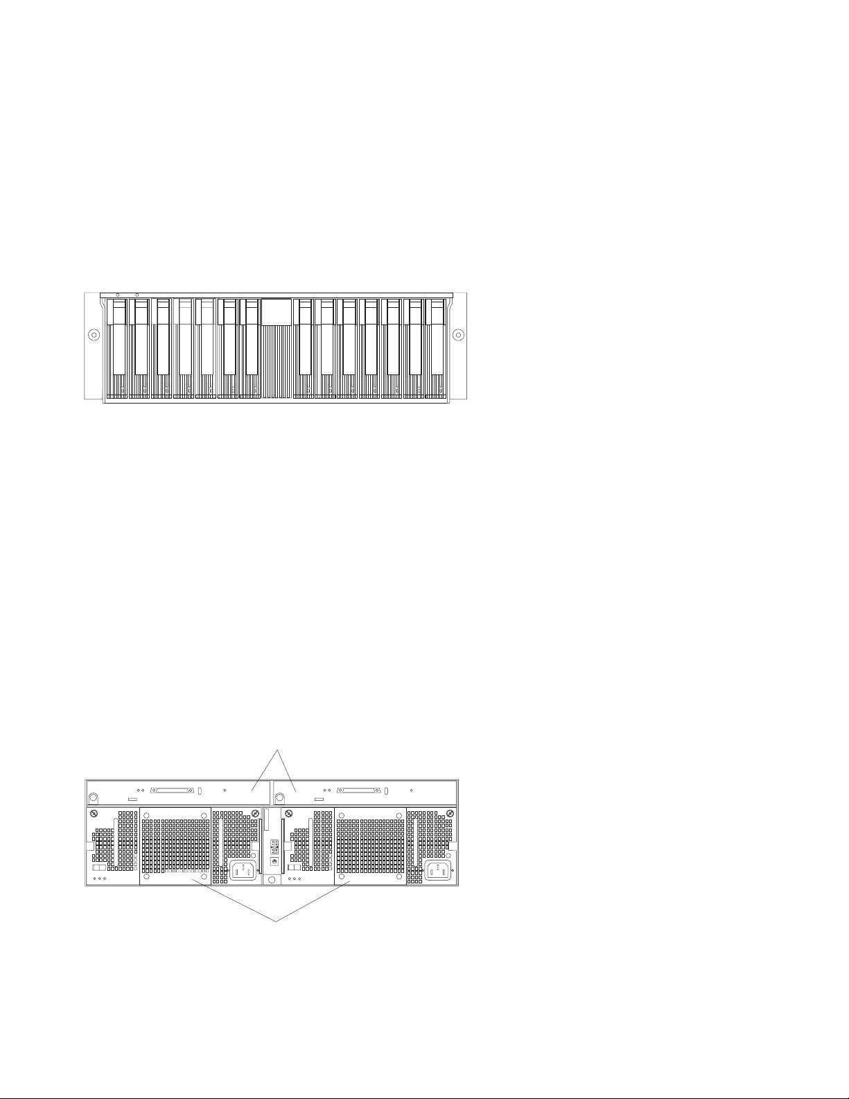
Hot-swap drive bays
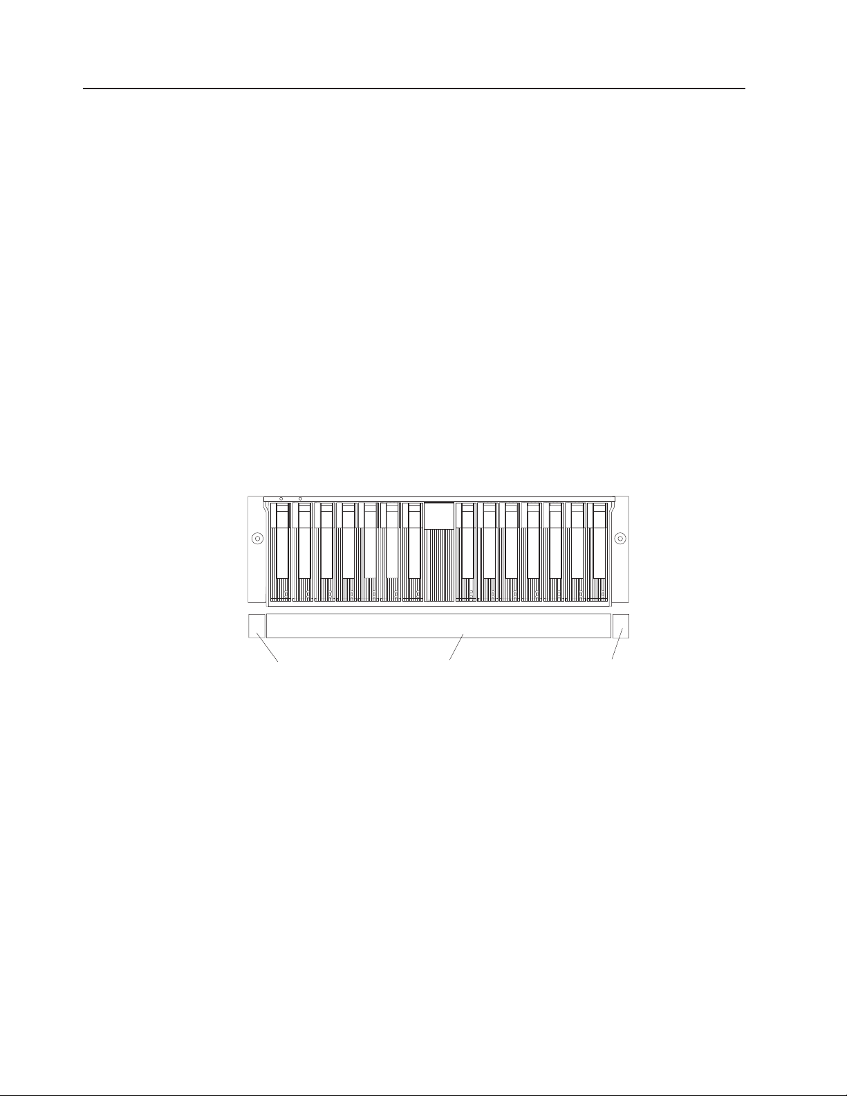
The following illustration shows the location of the hot-swap drive bays accessible
from the front of your storage unit. The storage unit supports 14 IBM Ultra160 SCSI
hard disk drives. These drives come pre-installed in a drive tray. The drive and tray
assembly is called a drive CRU (customer replaceable unit). You can install the
drive CRUs in the 14 drive bays on the front of the storage unit.
Attention: Never hot-swap a drive CRU when its green activity light emitting
diode (LED) is flashing. Hot-swap a drive CRU only when its amber fault LED is lit
(not flashing) or when the drive is inactive with the green activity LED off (not
flashing).
Bridge card bay
The bridge card is accessible from the front of the unit. You can replace the bridge
card CRU, but you must turn off the storage unit before doing so. See “Replacing a
bridge card” on page 23 for step-by-step instructions.
Attention: Never remove the bridge card while the storage unit is turned on. See
“Turning the storage unit on and off” on page 17.
ESM and power supply bays
The following illustration shows the location of the environmental services monitor
(ESM) bays (for the hot-swap ESM boards) and the power supply bays where the
hot-swap power supplies are located.
Hot-swap ESM bays
0
1
9
2
8
3
7
4
6
5
Hot-swap power supply/fan bays
Hot-swap ESM bays
The ESM boards provide a SCSI interface to the drives and monitor the
overall status of the storage unit. See “Replacing an ESM board” on
page 25 for more information.
2 5194 Network Attached Storage Model EXU Installation and User’s Guide
Page 13

Switch card bay
Hot-swap power supply/fan bays
Your storage unit comes with two 500 Watt hot-swap and redundant power
supplies with built-in fans. The power supplies are redundant in that a single
power supply can provide adequate power and cooling for the entire
storage unit. A single power supply supports 14 hard disk drives; however,
both power supplies must be installed, even if one power supply is not
operational. See “Working with hot-swap power supply/fan units” on
page 26 for step-by-step instructions.
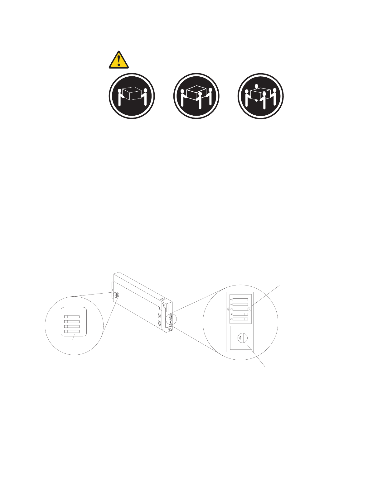
Your storage unit comes with a switch card that contains five external option
switches and four internal option switches. The switch card is located on the back
of the storage unit between the two power supplies. The switch card contains
switches that control how power is supplied to the storage unit and what storage
unit services are enabled. The internal option switches are preset to the default
position (Off). To access the four internal option switches, you must turn off the
storage unit; then remove the switch card. See “Replacing the switch card” on
page 24 for step-by-step instructions.
Attention: Never remove the switch card or change the switch card settings
while the storage unit and host server is turned on. Refer to “Turning the storage
unit on and off” on page 17.
In addition to the internal and external option switches, the switch card also has a
10-position unit ID switch for setting the storage unit ID using values 0 through 9.
System-management software, such as IBM Netfinity Manager
™
, uses the ID when
it provides data and alerts for the storage unit.
For more information on option switch settings, see “Setting the interface options
and ID settings” on page 11.
The following illustration shows the location of the switch card on the storage unit.
Chapter 1. Introduction 3
Page 14

External option switches
Switch card
0
1
9
2
8
3
7
4
6
5
1
2
3
4
5
3
2
4
1
5
0
6
9
7
8
Unit ID switch
Front controls, indicators, and devices
The primary controls on the front of the storage unit are shown in the following
illustration.
Power-on LED (green)
This green LED indicates that the unit has good dc power.
General-system-error LED (amber)
When lit, this amber LED indicates that the unit has a fault, such as in a
power supply, ESM board, or hard disk drive.
Bridge card bay
This is the location of the bridge card CRU.
Drive bays
There are 14 drive bays.
Latch This multipurpose blue latch releases or locks the drive CRU in place.
4 5194 Network Attached Storage Model EXU Installation and User’s Guide
Page 15
Tray handle
You can use this multipurpose handle to insert or remove a drive CRU.
Fault LED (amber)
Each drive CRU has a fault LED. When lit, this amber LED indicates a drive
failure. When flashing, this amber LED indicates that a drive Identify or
Rebuild is in progress.
Activity LED (green)
Each drive CRU has an activity LED. When flashing, this green LED
indicates drive activity.
Drive CRU
Each drive CRU consists of a slim hard disk drive and tray.
Rear controls, indicators, and connectors
Two hot-swap power supplies with built-in fans and two environmental services
monitor (ESM) boards are accessible from the back of the storage unit. These
components contain several user indicators and connectors.
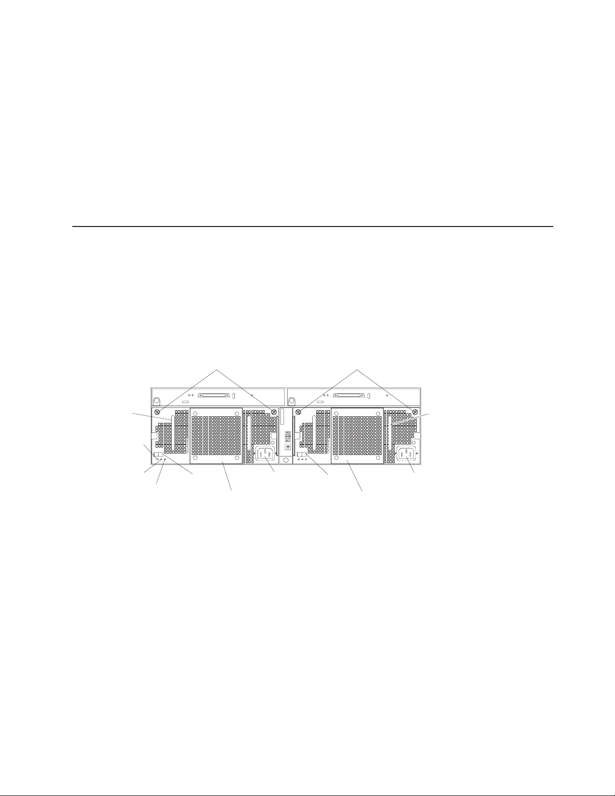
Power-supply controls, indicators, and connectors
The following is a list of the controls, indicators, and connectors at back of the
storage unit. A description of each item is included:
Handle Handle
AC power LED (green)
DC power LED (green)
Fault LED (amber)
Thumbscrews Thumbscrews
0
1
9
2
8
3
7
4
6
5
Power
on/off
switch
supply/Fan CRU
Power
Power
on/off
switch
supply/Fan CRU
Thumbscrews
Loosen the thumbscrews to remove or install a power supply.
AC power connector
The power cord for the power supply connects here.
Power-supply/Fan CRU
The two hot-swap power supplies with built-in fans are located on the back
of the storage unit.
Attention: The storage unit comes with two power-supply/fan units
installed. When one power supply fails, the power-supply unit must be
replaced to re-establish redundancy. When replacing the failed unit with the
new power supply unit, ensure that this operation is performed in less than
10 minutes to prevent any overheating.
AC power connectorAC power connector
Power
The fan that is visible from the rear of the power supply is an auxiliary fan
that is normally off. This fan turns on only when the main fan within the
power supply fails.
Chapter 1. Introduction 5
Page 16
Power on/off switch
Use this switch to turn the power supply on and off.
Fault LED (amber)
When completely lit, this amber fault LED indicates a power supply failure
or that a redundant power supply is not on. This LED also flashes when the
built-in fan fails.
DC power LED (green)
This green LED is lit when the storage unit is turned on and is supplying
both 5 V and 12 V dc power.
AC power LED (green)
This green LED is lit when the storage unit is receiving ac power.
Handles
The two handles are used for installing and removing the power supply.
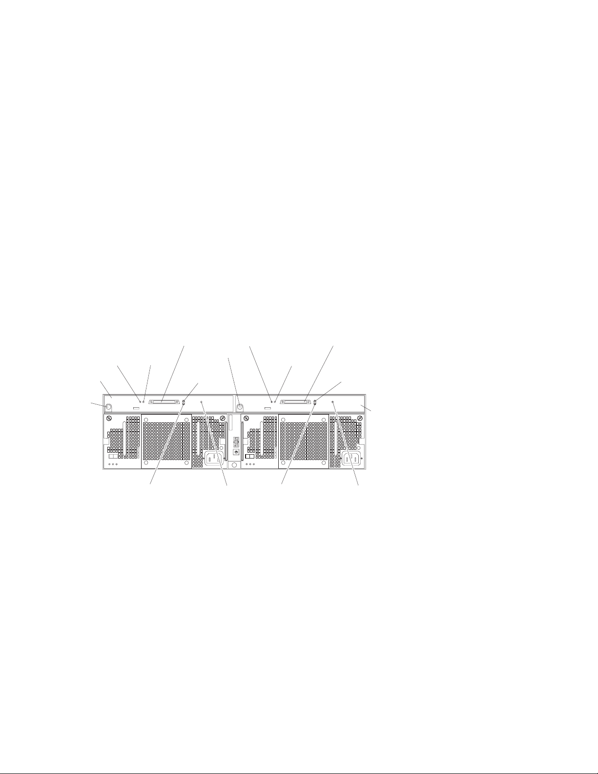
ESM board user controls
Two environmental services monitor (ESM) boards are accessible from the back of
the storage unit. These components contain several user controls, indicators, and
connectors.
Termination-
LED (green)
ESM board
Push pin
power
LVD/SE
LED (green)
SCSI reset
LED (green)
ESM board
Fault LED (amber)
SCSI reset LED
SCSI Bus
connector 2
Activity
LED (green)
Termination-
power
LED (green)
Push pin
0
1
9
2
8
3
7
4
6
5
Fault
LED (amber)
LVD/SE
LED (green)
SCSI reset
LED (green)
SCSI Bus
connector 1
Activity
LED (green)
ESM board
Fault
LED (amber)
The environmental services monitor (ESM) boards contain the SCSI
controls, LEDs, and connectors.
When lit, this amber LED indicates an ESM board failure.
When lit, this green LED indicates a SCSI bus reset.
Push pins
Each ESM board has an orange push pin at the lower left of the board. Use
the orange push pin and lever to remove and insert the ESM board.
Termination-power LED (green)
When lit, this green LED indicates that termination power is present. When
a termination-power LED is lit, it indicates that the other end of the cable is
connected to a powered-on controller. Each external bus has a separate
termination-power LED.
6 5194 Network Attached Storage Model EXU Installation and User’s Guide
Page 17

LVD/SE LED (green)
When lit, this green LED indicates that the external host bus is in low
voltage differential (LVD) mode. When this LED is off, this indicates that the
external host bus is in single-ended (SE) mode. Each external bus has a
separate LVD/SE LED. Only LVD host bus controllers are supported.
SCSI bus connector
The 68-pin Very High Density Connector Interface (VHDCI) connectors are
for attaching your SCSI cables to SCSI bus 1 and SCSI bus 2.
Activity LED (green)
When lit, this green LED indicates there is activity on the external SCSI
bus. Each external bus has a separate activity LED.
System-management software support
The storage unit provides software alert functions through the system monitor
functions provided in the IBM Netfinity Manager, IBM Netfinity Director, and IBM
ServeRAID manager software.
The following alerts are supported:
v Disk drive disabled
v Power supply failure
v Cooling failure
v Storage unit too hot
v Vital Product Data for subcomponents
Note: You must have the correct level of system-management software on your
server to enable this functionality.
You must use ServeRAID Version 4.20 or later for your ServeRAID controller to
report status and alerts properly. To download the latest ServeRAID software, visit
the IBM Web site at:
www.ibm.com/storage/support/nas
For up-to-date information about the IBM Netfinity Manager and Netfinity Director
software support available for your storage unit, visit the IBM Web site at:
www.ibm.com/storage/support/nas
For Netfinity Manager users, download Netfinity Manager Version 5.20.6 SP1 or
later.
For Netfinity Director users, download Netfinity Director, UM Server extensions
Version 2.12 SP1.
Chapter 1. Introduction 7
Page 18

8 5194 Network Attached Storage Model EXU Installation and User’s Guide
Page 19

Chapter 2. Installing the storage unit
You can install the storage unit in an Electronic Industries Association (EIA) 310
standard rack.
You will need a flat-blade screwdriver and a Phillips-head screwdriver to install your
storage unit. Each type of enclosure comes with general installation instructions for
installing optional devices.
Operating specifications
The following table summarizes the operating specifications of the storage unit.
Electrical input
v Sine-wave input (50 to 60 Hz) is
required
v Input voltage:
– Low range:
- Minimum: 90 V ac
- Maximum: 127 V ac
– High range:
- Minimum: 198 V ac
- Maximum: 257 V ac
– Input kilovolt-amperes (kVA)
approximately:
- Minimum configuration: 0.06
kVA
- Maximum configuration: 0.45
kVA
Environment
v Air temperature:
– storage unit on: 10° to 35° C
(50° to 95° F) Altitude: 0 to 914
m (3000 ft)
– storage unit on: 10° to 32° C
(50° to 90° F) Altitude: 914 m
(3000 ft.) to 2133 m (700 ft)
v Humidity: 8% to 80%
Size (with front panel and without
mounting rails)
v Depth: 53.8 cm (21.2 in)
v Height: 12.8 cm (5 in)
v Width: 44.7 cm (17.6 in)
Weight
Typical storage unit fully loaded: 36.1
kg (79.4 lbs)
Acoustical noise emissions values
For open bay (no drives installed) and
maximum system configurations (14
hard disk drives installed).
v Sound power (idling):
– 5.6 bels (open bay)
– 5.7 bels (typical)
v Sound power (operating):
– 5.6 bels (open bay)
– 6.5 bels (typical)
v Sound pressure (idling):
– 44 dBA (open bay)
– 47 dBA (typical)
v Sound pressure (operating):
– 44 dBA (open bay)
– 54 dBA (typical)
These levels are measured in
controlled acoustical environments
according to ISO 7779 and are
reported in accordance with ISO
9296. The declared sound power
levels indicate an upper limit, below
which a large portion of machines
operate. Sound pressure levels in
your location might exceed the
average 1-meter values stated
because of room reflections and other
nearby noise.
Inventory checklist
After you fully unpack your storage unit, verify that you have the following items:
v Hardware:
– IBM TotalStorage Network Attached Storage 200 Storage Unit
– Two power cords
– One 2 m (6.56 ft) SCSI cable
– One sheet of storage unit ID (0-9) labels
– One sheet of four SCSI ID labels
© Copyright IBM Corp. 2001 9
Page 20

Getting started
– One rack-mounting hardware kit
- Two rails (right and left assembly)
- Two M5 screws
- Ten M6 screws
- Ten M6 cage nuts
- Ten M6 clip nuts
v Publications:
– IBM TotalStorage Network Attached Storage 200 Storage Unit Installation and
User’s Guide (this book)
– IBM Safety Book
– Template for installing the storage unit in a rack
If an item is missing or damaged, contact your IBM reseller or your IBM marketing
representative.
If you have not already done so, take a moment to review the information in this
chapter and record your storage unit serial number in the table in “Identification
numbers” on page 35. Then, return to this chapter to begin the installation process.
Before you begin, review the following assumptions:
v If you are installing the storage unit in a rack, you have already installed the
other components in the rack and moved the rack to its permanent operating
location.
v The installation site meets all area, environmental, power, and site requirements
for the storage unit. See the storage unit requirements listed under “Operating
specifications” on page 9.
Preparing the storage unit
This section explains how to remove the CRUs and set the option switches to
prepare the storage unit for installation.
Removing CRUs
Attention: Static electricity, though harmless to you, can seriously damage
storage unit components or options. See “Handling electrostatic discharge-sensitive
devices” on page 54 for details.
Attention: If you have data stored on the drives, label the drives before you
remove them. Then, when you replace the drives, install each one in the same
drive bay from which you removed it. Failure to do so could result in a loss of data.
See “Chapter 3. Installing and replacing devices” on page 21 for information on
removing the CRUs.
It is easier to lift the storage unit and install it in a rack if you remove all CRUs (disk
drives, power supplies, and ESMs) first. A fully loaded storage unit with 14 hard disk
drives and two power supplies installed weighs 36.1 kg (79.5 lb). If you remove all
the CRUs, you can reduce the overall weight.
10 5194 Network Attached Storage Model EXU Installation and User’s Guide
Page 21
Statement 4
≥18 kg (37 lbs) ≥32 kg (70.5 lbs) ≥55 kg (121.2 lbs)
CAUTION:
Use safe practices when lifting.
Setting the interface options and ID settings
When you install a drive CRU in the storage unit, the drive tray plugs into a printed
circuit board called the midplane. The midplane sets the SCSI bus number and ID
automatically.
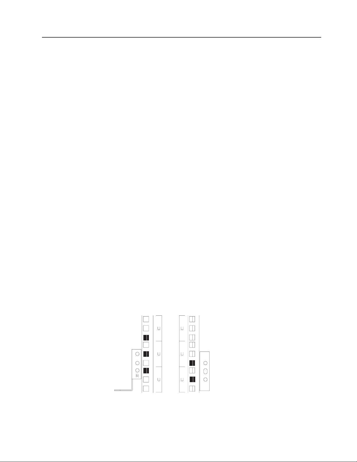
The switch card located on the back of the storage unit has five external option
switches, four internal option switches, and a unit ID switch. It is easier to set these
switches before you install the storage unit in a rack or tower enclosure.
On
1
2
3
4
Internal
options switches
Attention: Always set the option switches while the storage unit and host server
are turned off. Failure to do so will result in loss of data. See “Turning the storage
unit on and off” on page 17.
External option switches
3
4
2
5
1
6
0
7
9
8
3
2
4
1
5
0
6
9
7
8
Unit ID switch
External option switches
The five option switches on the exterior of the switch card are: Option switch 1
controls the power supply to the storage unit. Option switches 2 through 5 are
reserved; leave these switches in the default positions.
Option switch 1 — Power-control switch
When this option switch is set to Off, the storage unit turns on and off
automatically when you turn the host machine on and off. This occurs only
if termination power is present (the termination-power LED is on) at the
external SCSI connector.
Chapter 2. Installing the storage unit 11
Page 22

When this option switch is set to On (the default), you must turn the storage
unit on and off separately.
Option switches 2 through 5 — Reserved
These option switches are reserved; leave these option switches set to the
default positions. Set switches 2 through 5 (On, On, Off, Off) respectively.
Internal option switches
All internal option switches must be set in the Off (default) position.
Unit ID switch
The unit ID switch has 10 settings. You can use these settings (0 through 9) to set
an ID for the storage unit. System-management software, such as IBM Netfinity
Director, uses this storage unit ID when it provides data and alerts for the storage
unit.
The Unit ID switch comes with a factory default of ID 0. Because each 5194-EXU is
on a separate SCSI channel connected to the Model 225’s SCSI RAID card, you
can leave this Unit ID configuration as ID 0 for any attached 5194-EXU units.
12 5194 Network Attached Storage Model EXU Installation and User’s Guide
Page 23
Installing the storage unit in a rack
The storage unit requires 3U (5.25 in) of Electronic Industries Association (EIA)
rack-mounting space.
Attention: Static electricity, though harmless to you, can seriously damage
storage unit components or options. See “Handling electrostatic discharge-sensitive
devices” on page 54 for details.
Important: Review the documentation that comes with your rack enclosure for
safety and cabling considerations. When installing your storage unit in a rack, take
the following precautions:
v Read “Removing CRUs” on page 10 about making the storage unit easier to
handle.
v Install the storage unit in a maximum 35 degree C environment.
v To ensure proper air flow, do not block the air vents; usually 15 cm (6 inches) of
air space is sufficient.
Note: Because of the limited space in some racks, it might be easier to connect
and route cables before you install the mounting brackets and hardware
devices.
v To ensure stability, take precautions to prevent uneven loading of the rack.
Loading of the rack should begin at the bottom.
v When multiple components are installed in a rack, take precautions to prevent
overloading of the power outlets.
v The storage unit should always be connected to a properly grounded outlet.
v Refer to the rack documentation for instructions on removing the rack enclosure
doors and side panels.
Use the rack-mounting template and installation instructions that come with the
storage unit to locate the rack-mounting holes and to install the unit in a rack
cabinet. If you do not have the template and instructions, you can use the following
steps to install your storage unit:
1. Use the following illustration of the front and rear rack mounting flanges to
determine the appropriate rack-mounting holes for installing cage nuts or clip
nuts to secure the storage unit rails. From left to right, the illustration shows
the front and rear flanges respectively.
Front Rear
Chapter 2. Installing the storage unit 13
Page 24
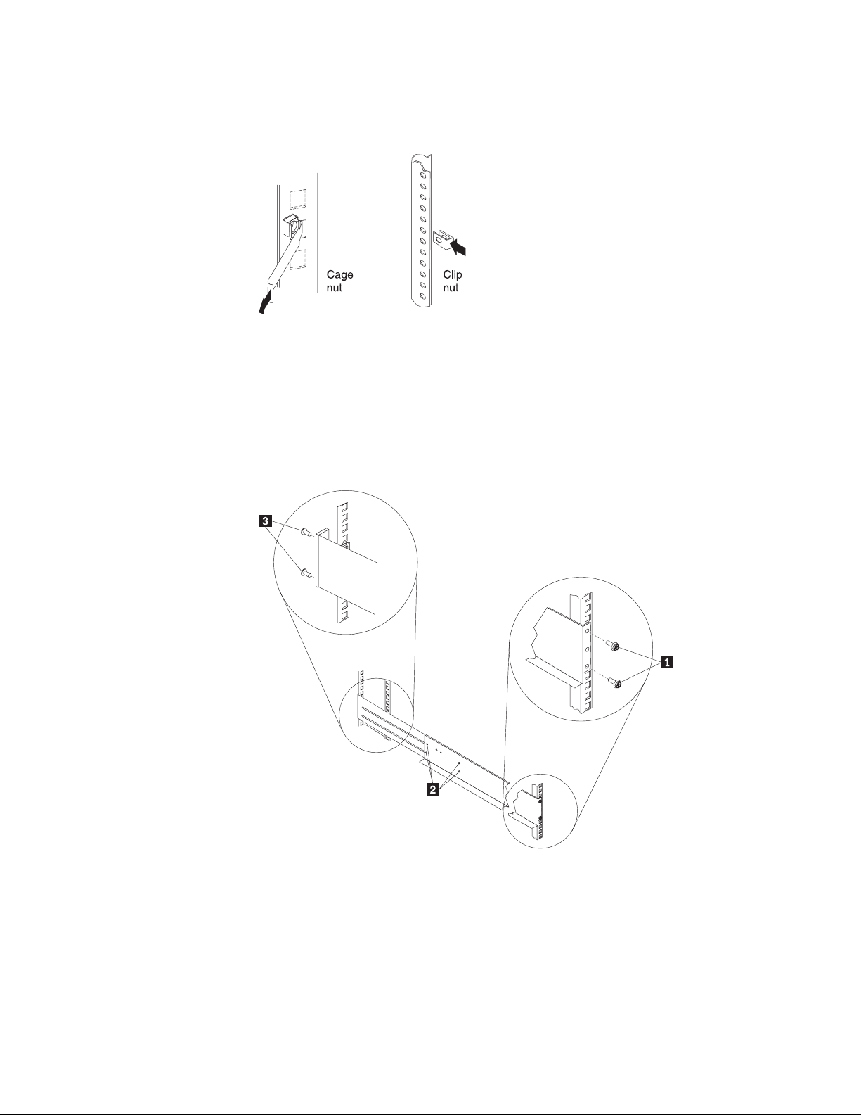
Note: Use clip nuts if your rack has holes. If your rack has square holes, you
can use the rack-insertion tool or a flat-blade screwdriver to install cage
nuts.
2. On the rail marked R, loosen the four screws2.
3. Hold the rail against the outside of the right rack-mounting flange, and loosely
insert the two front M6 screws 1.
4. Extend the rail outside of the rear rack-mounting flange; then, install and
tighten two rear M6 screws 3.
5. Tighten the two front screws 1; then, tighten the four screws 2.
Repeat step 2 through step 5 to install the rail marked L on the left side of the
rack.
14 5194 Network Attached Storage Model EXU Installation and User’s Guide
Page 25
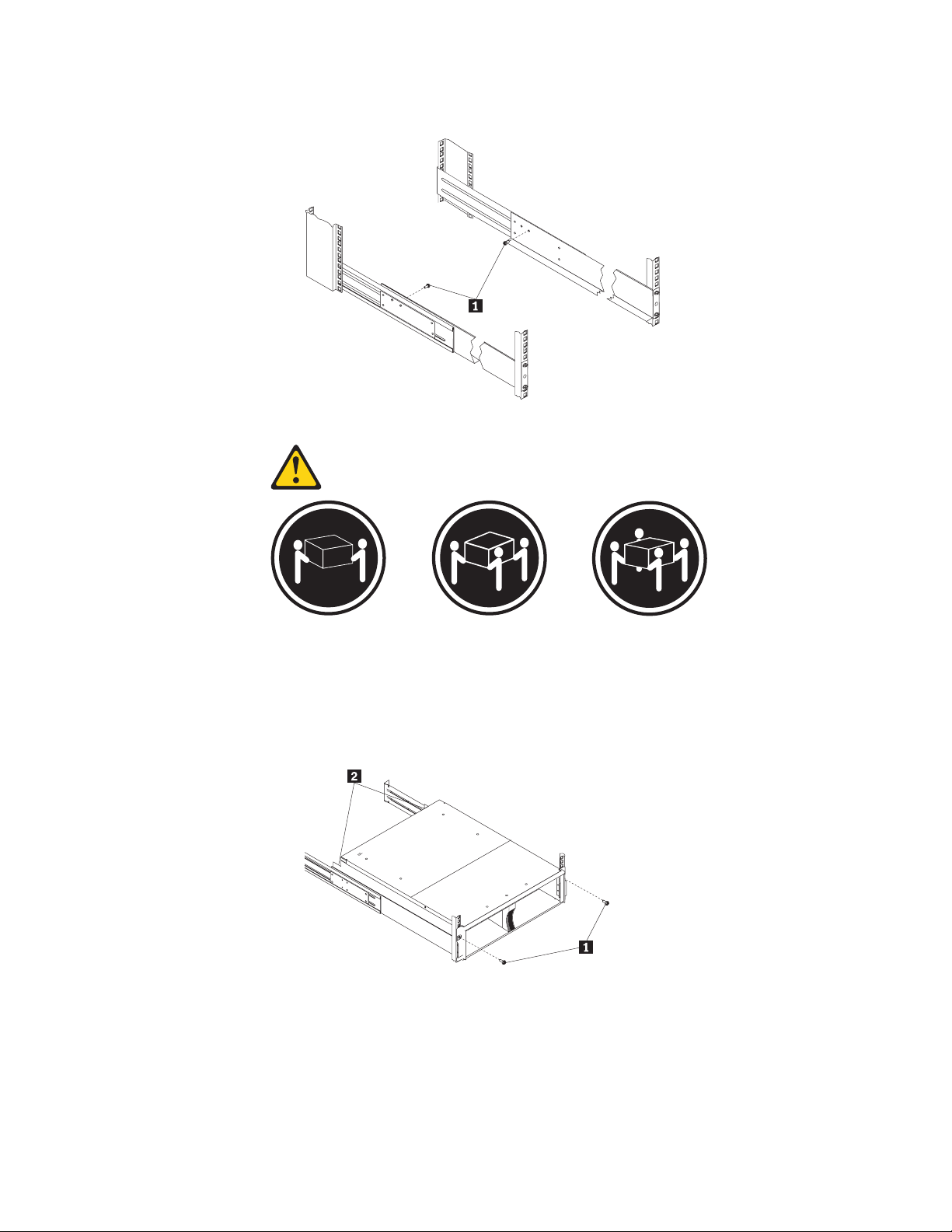
6. Loosely insert one M5 screw 1 into each rail.
Statement 4
≥18 kg (37 lbs) ≥32 kg (70.5 lbs) ≥55 kg (121.2 lbs)
CAUTION:
Use safe practices when lifting.
7. Slide the storage unit into the rack, and insert the M6 screws 1.Donot
overtighten the M6 1 screws.
8. Tighten the rear screws 2.
9. Verify that option switches 1 and 2 (inside the switch card) are set to Off. See
“Setting the interface options and ID settings” on page 11 for more information.
10. Install hard disk drives and power supplies in the storage unit according to
“Chapter 3. Installing and replacing devices” on page 21; then, return here to
complete the installation.
11. Continue with “Completing the installation” on page 16.
Chapter 2. Installing the storage unit 15
Page 26
Completing the installation
After you install the hard disk drives and power supplies, follow the instructions in
this section to complete the installation. Instructions for installing the identification
labels and cabling the storage unit are included.
Installing identification labels
Your storage unit comes with one sheet of 10 labels (0-9) and one sheet of 4 labels
(SCSI ID) labels.
Complete the following steps to install the SCSI identification labels:
To install the label:
1. Locate the SCSI ID label for your configuration. Use the single-bus label as
illustrated below.
a. Orient the label so that the printed numbers are legible from left-to-right.
b. Peel the backing away from the adhesive side of the label.
c. Carefully butt the edge of the SCSI ID label up against the edge of the serial
number label so that the 14 printed ID numbers are located beneath each of
the drive bays.
d. Apply the label to the front of the unit, as shown in the following illustration.
0
1234
Expansion unit ID label
5
69810
SCSI ID label
11 12
13
14
Serial number label
16 5194 Network Attached Storage Model EXU Installation and User’s Guide
Page 27

2. Install the storage unit ID label.
3.
a. Verify the setting of the storage unit number switch (0-9).
b. Apply the storage unit ID label that matches the setting for the unit ID switch
in the blank label area directly to the left of the SCSI ID label.
4. Continue with “Cabling the storage unit”.
Cabling the storage unit
This section provides the SCSI and power cabling information. After you attach your
SCSI and power cables, use the instructions provided in “Turning the storage unit
on and off” for the initial startup of the storage unit.
SCSI cabling information
The storage unit comes with two ESM boards. There are two 68-pin SCSI Very
High Density Connector Interface (VHDCI) connectors. From left to right as seen
from the back, these connectors are for SCSI bus 2 and SCSI bus 1. See “Rear
controls, indicators, and connectors” on page 5 for the location of these connectors.
Note: Connect only the SCSI bus 1 (right side) connector to the 5194-225. SCSI
bus 2 (left side) is not used.
SCSI cable restriction
The SCSI controller inside your engine must have a dedicated SCSI channel for the
storage unit. If an external channel is being used for the storage unit, its
corresponding internal channel must not be used for other devices.
Power cabling
The storage unit uses two power cords. You can connect the power cords to a
primary power unit inside the rack, such as a properly grounded ac distribution unit
or uninterruptible power supply (UPS), or to an external source, such as a properly
grounded electrical outlet.
Attach the power supply power cords as follows:
1. Connect the power cord to the power supply.
2. Plug the power supply cord into a properly grounded electrical outlet.
3. Go to “Turning the storage unit on and off” for information about the initial
startup of the storage unit.
Turning the storage unit on and off
This section contains instructions for turning the storage unit on and off under
normal and emergency circumstances.
If you are turning on the storage unit after an emergency shutdown or power
outage, see “Turning on the storage unit after an emergency” on page 19.
Turning on the storage unit
Use this procedure to turn on the power for the initial startup of the storage unit.
1. Verify that:
a. All cables are properly attached.
b. Both power cords are plugged into the back of the storage unit and into
properly grounded electrical outlets.
c. All hard disk drives are locked securely in place.
Chapter 2. Installing the storage unit 17
Page 28
d. All switches are set correctly: the internal option switches 1 through 4,
external option switches 1 through 5, and the unit ID switch on the storage
unit. See “Setting the interface options and ID settings” on page 11 for more
information.
2. Ensure engine is up and running before you continue with Step 3.
3. Turn on both power supplies on the back of the storage unit.
The storage unit might take a few seconds to turn on. During this time, you
might see the fault (amber) and the power (green) LEDs on the storage unit turn
on and off intermittently. When the power-on sequence is complete, only the
power (green) LEDs on the front and back should remain on. If one or more
fault (amber) LEDs remain lit, see “Troubleshooting” on page 29.
Attention: If you have data stored on the drives, label the drives before you
remove them. Then, when you replace the drives, install each one in the same
drive bay from which you removed it. Failure to do so will result in a loss of
data.
Turning off the storage unit
Attention: Except in an emergency situation, never turn off the power if any fault
LEDs are lit on the storage unit. Correct the fault before you attempt to turn off the
power, using the proper troubleshooting or servicing procedure. This will ensure that
the storage unit will turn on correctly later. Refer to “Troubleshooting” on page 29.
Statement 5
CAUTION:
The power control button on the device and the power supply do not turn off the
electrical current supplied to the device. The device also might have more than one
power cord. To remove all electrical current from the device, ensure that all power
cords are disconnected from the power source.
2
1
The storage unit is designed to run continuously, 24 hours a day. Turn off the power
only when at least one of the following is true:
v Instructions in a hardware or software procedure require you to turn off the
power.
v A service technician tells you to turn off the power.
v A power outage or emergency situation occurs, see “Turning off the storage unit
in an emergency” on page 19.
Use the following procedure to turn off the storage unit:
1. Power down the server attached to the storage unit.
2. Make sure that all amber fault LEDs are off. If any fault LEDs are lit (drives,
power supplies, or ESM boards), correct the problem before you turn off the
power. For guidance, see “Troubleshooting” on page 29.
3. Turn off both power supplies.
18 5194 Network Attached Storage Model EXU Installation and User’s Guide
Page 29

Turning off the storage unit in an emergency
Attention: Emergency situations might include fire, flood, extreme weather
conditions, or other hazardous circumstances. If a power outage or emergency
situation occurs, always turn off all power switches on all computing equipment.
This will help safeguard your equipment from potential damage due to electrical
surges when power is restored. If the storage unit loses power unexpectedly, it
might be due to a hardware failure in the power system or midplane. See
“Troubleshooting” on page 29.
Use the following procedure to turn off the storage unit during an emergency
situation:
1. Power down the server attached to the storage unit.
2. If you have time, stop all activity and check the LEDs (front and back). Make
note of any fault LEDs that are lit so that you can correct the problem when you
turn on the power again.
3. Turn off all power supplies; then, unplug the power cables from the storage unit.
Turning on the storage unit after an emergency
Use the following procedure to restart the storage unit if you turned off the power
supplies during an emergency shutdown, or if a power failure or a power outage
occurred:
1. After the emergency situation is over or power is restored, check the storage
unit for damage. If there is no visible damage, continue with Step 2; otherwise,
have your unit serviced.
2. Ensure engine is up and running before you continue with Step 3.
3. After you have checked for damage, plug in the storage-unit power cables and
turn on the power switches.
4. Turn on both power supplies on the back of the storage unit.
5. Only the power (green) LEDs on the front and back should be on. If one or
more of the fault (amber) LEDs are on, see “Troubleshooting” on page 29 for
instructions.
6. Use your installed software application as appropriate to check the status of the
storage unit.
Chapter 2. Installing the storage unit 19
Page 30

20 5194 Network Attached Storage Model EXU Installation and User’s Guide
Page 31

Chapter 3. Installing and replacing devices
This chapter provides instructions for installing or replacing customer replaceable
units (CRUs), such as hot-swap drives, ESM boards, the bridge card, the switch
card, and power supplies.
Attention: If you have data stored on the drives, label the drives before you
remove them. Then, when you replace the drives, install each one in the same
drive bay from which you removed it. Failure to do so could result in a loss of data.
Attention: Static electricity can seriously damage storage unit components or
options. See “Handling electrostatic discharge-sensitive devices” on page 54 for
details.
Attention:
It is easier to lift the storage unit if you remove all CRUs (disk drives, power
supplies, and ESMs) first. A fully loaded storage unit with 14 hard disk drives and
two power supplies installed weighs 36.1 kg (79.5 lb). The standard unit with two
power supplies weighs 22.5 kg (49.5 lb). If you remove all the CRUs, you can
reduce the overall weight.
Statement 4
≥18 kg (37 lbs) ≥32 kg (70.5 lbs) ≥55 kg (121.2 lbs)
CAUTION:
Use safe practices when lifting.
Working with hot-swap drives
Before you begin
v Read the safety and handling guidelines provided in “Appendix D. Safety notices” on
page 51.
v Ensure that your current system configuration is working properly.
v Back up all important data before you make changes to storage devices, such as hard
disk drives.
© Copyright IBM Corp. 2001 21
Page 32

Before you replace drive CRUs, review the following information:
Replacing hot-swap drives
Drive problems include any malfunctions that delay, interrupt, or prevent successful
I/O activity between the hosts and the hard disk drives in the storage unit. This
includes transmission problems between the host controllers, the ESM boards, and
the drives. This section explains how to replace a failed drive.
Attention: Failure to replace the drives in their correct bays might result in loss
of data. If you are replacing a drive that is part of a RAID level 1 or RAID level 5
logical drive, ensure that you install the replacement drive in the correct bay.
Check the hardware and software documentation provided with your system to see
if there are restrictions regarding hard disk drive configurations. Some system SCSI
configurations might not allow mixing different drive capacities or types within an
array.
To replace a hot-swap drive:
1. Determine the location of the drive that you want to remove.
Attention: Never hot swap a drive CRU when its green activity LED is
flashing. Hot swap a drive CRU only when its amber fault LED is lit (not
flashing) or when the drive is inactive (activity LED is off).
2. Remove the drive CRU.
a. Press on the inside of the bottom of the tray handle 2to release the blue
latch 1.
b. Pull the handle 2 on the tray 3 out into the open position.
c. Lift the drive tray partially out of the bay.
d. To avoid possible damage to the drive 4, wait at least 20 seconds before
fully removing the drive CRU from the storage unit, to allow for the drive to
spin down.
e. Verify that there is proper identification (such as a label) on the drive CRU
and then slide it completely out of the storage unit.
22 5194 Network Attached Storage Model EXU Installation and User’s Guide
Page 33

3. Install the new drive CRU.
a. Gently push the drive CRU into the empty bay until the tray handle 2
touches the storage unit tray.
b. Push the tray handle 2 down into the closed (latched) position.
4. Check the drive LEDs.
a. When a drive is ready for use, the green activity LED and the amber fault
LED are off.
b. If the amber fault LED is on, remove the drive from the unit and wait 10
seconds; then, reinstall the drive.
ServeRAID information In some cases, the ServeRAID controller will automatically reset
the drive to the Hot Spare or Rebuild state. If the drive state change does not occur
automatically (amber LED stays lit), refer to your ServeRAID documentation for information
about manually changing the state of the drive from the current state to another state, such
as Hot Spare or Ready. The amber LED should turn off within 10 seconds after the
drive-state change.
Working with cards and boards
Before you begin
v Read the safety and handling guidelines provided in “Appendix D. Safety notices” on page 51.
v Ensure that your current system configuration is working properly.
v Back up all important data before you make changes to storage devices, such as hard disk drives.
The storage-unit bridge card, switch card, and ESM boards are customer
replaceable units (CRUs). This section contains step-by-step instructions for
removing and replacing each device.
Replacing a bridge card
To replace the bridge card CRU in the storage unit, follow the instructions for
removing the bridge card and installing a bridge card.
Chapter 3. Installing and replacing devices 23
Page 34

Removing a bridge card
Attention: Before removing the storage unit bridge card, you must turn off the
storage unit. Refer to “Turning the storage unit on and off” on page 17, for detailed
instructions.
Complete the following steps to remove the storage unit bridge card:
1. Turn off the storage unit. See “Turning the storage unit on and off” on page 17.
2. Remove the drive CRUs from the left and right of the bridge card bay. See
“Replacing hot-swap drives” on page 22.
3. Squeeze the bridge-card cover 1 clips, and pull the bridge card cover 1 off.
4. Lift the tray handle 2, and pull the tray 3 that contains the bridge card out of
the bridge card bay.
Installing a bridge card
Attention: Make sure the storage unit is turned off before installing a bridge card.
See “Turning the storage unit on and off” on page 17.
Complete the following steps to install the storage unit bridge card:
1. Make sure the storage unit is turned off.
2. Hold the bridge card tray 3 so the tray handle 2 is at the top of the bridge
card tray and pointing outward.
3. Slide the tray 3 that contains the bridge card into the bridge card bay.
4. Push the tray handle 2 down, locking the bridge-card tray into place.
5. Replace the bridge card cover 1 by squeezing each of the four tabs, locking
the cover into place.
6. Replace the drive CRUs removed when you removed the bridge card.
7. Turn on the storage unit. See “Turning the storage unit on and off” on page 17.
Replacing the switch card
To replace the switch card CRU in the storage unit, follow the instructions for
removing the switch card and installing the switch card.
Removing the switch card
Attention: Before removing the switch card, be sure to turn off the storage unit.
See “Turning the storage unit on and off” on page 17. Make note of the switch card
settings so you can set the new card to the same settings. Failure to do so will
result in loss of data.
There is one switch card located between the two power supply/fan units at the
back of the unit. Complete the following steps to remove the switch card:
1. Turn off the storage unit.
24 5194 Network Attached Storage Model EXU Installation and User’s Guide
Page 35

2. Locate the blue push pin 2 at the bottom of the switch card tray.
3. Pull out the blue push pin 2.
4. Pull up on the switch-card tray handle 1.
5. Slide the tray that contains the switch card out of the switch card bay.
Installing a switch card
Attention: Before installing a new switch card, make sure that the switch card
settings are the same as the settings on the switch card being replaced, and that
the storage unit is turned off. See “Turning the storage unit on and off” on page 17.
Failure to do so will result in loss of data.
There is one switch card located between the two power supply/fan assemblies at
the back of the unit. Complete the following steps to install the switch card:
1. Make sure the storage unit is turned off.
2. Hold the switch card so the blue push pin 1 is at the bottom of the card and
the tray handle 2 is to the left of the card.
3. Hold the tray handle 2 up and slide the card 3into the bay until it stops.
4. Push the tray handle 2all the way down; then, push in the push pin 1.
Replacing an ESM board
To replace an ESM board CRU in the storage unit, follow the instructions for
removing an ESM board and installing an ESM board.
Removing an ESM board
There are two hot-swap ESM boards at the back of the unit. You can remove the
ESM board and SCSI cable without turning off power to the engine. Complete the
following steps to remove a storage unit ESM board:
1. Power down the storage unit.
2. Disconnect the SCSI cable 1from the ESM Board.
3. Locate the orange push pin 4 to the left of each ESM board.
4. Pull the orange push pin 4 out.
5. Holding the pin, pull the tray handle 3 out and to the right.
6. Slide the ESM board2out of the storage unit.
Chapter 3. Installing and replacing devices 25
Page 36

Installing an ESM board
There are two hot-swap ESM boards at the back of the unit. You can install the
ESM board and SCSI cable without turning off power to the engine. Complete the
following steps to install a storage unit ESM board:
1. Hold the board so the tray handle 3 is attached to the bottom of the tray and
the tray handle 3 is fully extended.
2. Slide the ESM board 2 into the bay and move the handle 3 to the closed
position (left) until it clicks.
3. Push in the orange push pin 4.
4. Connect the SCSI cable 1 to the ESM board.
5. Power on the storage unit.
Working with hot-swap power supply/fan units
Before you begin
v Read the safety and handling guidelines provided in “Appendix D. Safety notices” on page 51.
The power supplies are customer replaceable units (CRUs) and do not require
preventive maintenance.
v The power supplies must always be installed in the proper place to maintain
proper storage unit cooling.
v Use only the supported power supplies for your specific storage unit.
Removing a hot-swap power supply/fan unit
Complete the following steps to remove a hot-swap power supply:
1. Turn off the power supply.
2. Unplug the power supply cord from the electrical outlet.
3. Disconnect the power cord from the power supply.
4. Loosen the power supply thumbscrews 1.
5. Grasp the handles 2 on each side of the power supply and pull the unit out of
the storage unit.
26 5194 Network Attached Storage Model EXU Installation and User’s Guide
Page 37

0
9
1
8
2
7
3
6
4
5
Installing a hot-swap power supply/fan unit
Complete the following steps to install a hot-swap power supply:
1. Ensure that the power supply you are installing is turned off.
2. Grasp the handles2and slide the power supply into the storage unit.
3. Tighten the power supply thumbscrews 1.
4. Connect the power cord to the power supply.
5. Plug the supply power cord into a properly grounded electrical outlet.
If you just installed a second (redundant) supply, the fault (amber) LED will light
because its power switch is turned off.
6. Turn on the power supply.
If you just installed a second (redundant) supply, after you turn on the power,
the fault (amber) LED will turn off and the ac and dc power (green) LEDs will
turn on.
Chapter 3. Installing and replacing devices 27
Page 38

28 5194 Network Attached Storage Model EXU Installation and User’s Guide
Page 39

Chapter 4. Solving problems
This chapter contains information to help you solve some of the simpler problems
you might have with your storage unit. It contains the problem symptoms and error
messages along with suggested actions to take to resolve the problem.
This chapter also provides instructions on how to obtain service and technical
assistance for your storage unit and other IBM products that you might plan to use.
Note: To acquaint yourself with product warranty information, see “Appendix C.
Product warranties” on page 41.
Troubleshooting
You can use these charts to find solutions to problems that have definite symptoms.
Problem
indicator
Amber LED on Drive CRU Drive failure Replace the failed drive. See “Replacing hot-swap drives” on
Amber LED on
and green LED
off
Amber and
green LEDs on
All green LEDs
off
Amber LED
flashing
Amber LED on
and green dc
power LED off
Component Possible
cause
ESM board Board failure Replace failed board. See “Replacing an ESM board” on page 25.
Front panel General
machine fault
Powersupply
CRUs
Powersupply
CRUs
All CRUs The storage
Drive CRUs Drive rebuild
Power
supply CRU
Power
supply CRU
Power is
turned off
Power supply
failure
unit is turned
off
AC power
failure
Power supply
failed
Midplane
failure
or identity is
in process
Fan failure Replace the power supply CRU.
Power supply
failure
Possible solutions
page 22.
Indicates that a Fault LED somewhere on the storage unit has been
turned on. Check for amber LEDs and CRUs. See “Rear controls,
indicators, and connectors” on page 5
Turn on all power supplies. See “Rear controls, indicators, and
connectors” on page 5.
Replace the failed power supply CRU. See “Replacing an ESM
board” on page 25.
Check that all storage unit power cables are plugged in and the
power is on. If applicable, check that the main circuit breakers for the
rack are turned on.
If the external switch 1 is set to Off, the SCSI controller must be
cabled to the storage unit and turned on. See “External option
switches” on page 11.
Check the main circuit breaker and ac outlet.
Replace the power supply CRU. See “Removing a hot-swap power
supply/fan unit” on page 26.
Have the storage unit serviced.
No corrective action is needed.
If the power switch is on, replace the power supply CRU. See
“Removing a hot-swap power supply/fan unit” on page 26.
© Copyright IBM Corp. 2001 29
Page 40

Problem
indicator
Amber LED on
and green ac
power LED off
Green LED on Drive CRU
One or more
green LEDs off
Intermittent or
sporadic power
loss to the
storage unit
Unable to
access drives
on one or both
SCSI buses
Random errors Subsystem Midplane
Component Possible
cause
Power
supply CRU
ID=6
One or two
drive CRUs
All drive
CRUs or
those on
one bus
Front panel Power supply Make sure the cables are plugged in and power supplies are turned
Some or all
CRUs
Drives and
SCSI bus
Bridge card Bridge card
No ac power
to power
supply. Check
the ac power
cord (cable)
or breaker
Cluster
configuration
No activity to
the drives
No activity to
the drives
Damaged or
loose SCSI
cables
ESM board
failure
Midplane
failure
Hardware
failure
Defective ac
power source
or partially
plugged
power cable
Power supply
failure
Midplane
failure
Incorrect
SCSI ID
settings
ESM board
failure
failure
failure
Possible solutions
If ac power is good at the source, replace the power cord CRU. If
the power supply has failed, replace the power supply CRU. See
“Removing a hot-swap power supply/fan unit” on page 26.
If not currently cluster configured, power cycle the storage unit to
re-enable ID=6.
No action is required.
No action is required.
Check SCSI-bus cables and connections.
Use RAID management software to check the SCSI-bus status.
Replace the ESM board. See “Replacing an ESM board” on page 25.
Have the storage unit serviced.
on.
If any other LEDs are turned on, have the storage unit serviced.
Check the ac power source. Resecure all installed power cables and
power supplies. If applicable, check the power components (power
units, UPS, and so on). Replace defective power cables.
Check for a fault LED on the power supply and replace the failed
CRU. See “Installing a hot-swap power supply/fan unit” on page 27.
Have the storage unit serviced.
Make sure SCSI cables are undamaged and properly connected.
Check the drive SCSI ID settings. Ensure that option switches 1 and
3 (inside the switch card) are set to the appropriate positions.
Attention:
Change switch positions only when your host server and storage unit
is turned off.
Have the storage unit serviced.
All high address or all low address hard-disk drive failed; check the
bridge card CRU and replace if necessary. See “Replacing a bridge
card” on page 23.
Have the storage unit serviced.
Note: If you cannot find the problem in the troubleshooting chart, test the entire
system. See your User’s Reference and Service Guide for more detailed
information on testing and diagnostic tools.
30 5194 Network Attached Storage Model EXU Installation and User’s Guide
Page 41

If you already have run the appliance diagnostic program, or if running the
test does not reveal the problem, have the system serviced.
Getting help, service, and information
If you need help, service, technical assistance, or just want more information about
IBM products, you will find a wide variety of sources available from IBM to assist
you.
IBM maintains pages on the World Wide Web where you can get information about
IBM products and services and find the latest technical information.
Table 1 lists some of these pages.
Table 1. IBM Web sites for help, services, and information
www.ibm.com Main IBM home page
www.ibm.com/storage IBM Storage home page
www.ibm.com/storage/support/nas IBM NAS Support home page
You might also want to visit the Web pages of other companies for information
about other operating systems, software, and accessories. The following are some
other Web sites you might find helpful:
Service support
www.tivoli.com
www.cdpi.com
Services available and telephone numbers listed are subject to change without
notice.
With the original purchase of an IBM hardware product, you have access to
extensive support coverage. During the IBM hardware product warranty period, you
may call the IBM Support Center (1-800-426-7378 in the U.S.) for hardware product
assistance covered under the terms of the IBM hardware warranty. See “Getting
help by telephone” on page 33 for Support Center telephone numbers in other
countries.
The following services are available during the warranty period:
v Problem determination - Trained personnel are available to assist you with
determining if you have a hardware problem and deciding what action is
necessary to fix the problem.
v IBM hardware repair - If the problem is determined to be caused by IBM
hardware under warranty, trained service personnel are available to provide the
applicable level of service.
v Engineering change management - Occasionally, there might be changes that
are required after a product has been sold. IBM or your reseller, if authorized by
IBM, will make Engineering Changes (ECs) available that apply to your
hardware.
Be sure to retain your proof of purchase to obtain warranty service.
Please have the following information ready when you call:
v Machine Type and Model
Chapter 4. Solving problems 31
Page 42

v Serial numbers of your IBM hardware products
v Description of the problem
v Exact wording of any error messages
v Hardware and software configuration information
If possible, be at your computer when you call.
Note: A compatible monitor, keyboard, and mouse may be required for some
service activities. Before you have the computer serviced, be sure to have
these components attached to your computer, either directly or through a
console switch.
The following items are not covered:
v Replacement or use of non-IBM parts or nonwarranted IBM parts
Note: All warranted parts contain a 7-character identification in the format IBM
FRU XXXXXXX.
v Identification of software problem sources
v Configuration of BIOS as part of an installation or upgrade
v Changes, modifications, or upgrades to device drivers
v Installation and maintenance of network operating systems (NOS)
v Installation and maintenance of application programs
Refer to your IBM hardware warranty for a full explanation of IBM’s warranty terms.
Before you call for service
Many computer problems can be solved without outside assistance, by using the
online help or by looking in the online or printed documentation that comes with
your TotalStorage Network Attached Storage appliance. Also, be sure to read the
information in any README files that come with your software.
Your TotalStorage Network Attached Storage appliance comes with documentation
that contains troubleshooting procedures and explanations of error messages. The
documentation that comes with your appliance also contains information about the
diagnostic tests you can perform.
If you receive a POST error code or beep code when you turn on your TotalStorage
Network Attached Storage appliance, refer to the POST error-message charts in
your hardware documentation. If you do not receive a POST error code or beep
code, but suspect a hardware problem, refer to the troubleshooting information in
your hardware documentation or run the diagnostic tests.
If you suspect a software problem, consult the documentation (including any
README files) for the operating system or application program.
Note: For product warranty information, see “Appendix C. Product warranties” on
page 41.
Getting customer support and service
Purchasing an TotalStorage Network Attached Storage appliance entitles you to
standard help and support during the warranty period. If you need additional
support and services, a wide variety of extended services are available for purchase
that address almost any need.
32 5194 Network Attached Storage Model EXU Installation and User’s Guide
Page 43

Getting help online: www.ibm.com/storage/support/nas
Here you can visit a support page that is specific to your hardware, complete with
FAQs, parts information, technical hints and tips, technical publications, and
downloadable files, if applicable.
Getting help by telephone
During the warranty period, you can get help and information by telephone through
the IBM Support Center. Expert technical-support representatives are available to
assist you with questions you might have on the following:
v Setting up your TotalStorage Network Attached Storage appliance
v Arranging for service
v Arranging for overnight shipment of customer-replaceable parts
In addition, if you purchased a TotalStorage Network Attached Storage appliance,
you are eligible for IBM up and running support for 90 days after installation. This
service provides assistance for:
v Setting up your TotalStorage Network Attached Storage appliance
v Limited configuration assistance
Please have the following information ready when you call:
v Machine Type and Model
v Serial numbers of your appliance and other components, or your proof of
purchase
v Description of the problem
v Exact wording of any error messages
v Hardware and software configuration information for your system
If possible, be at your computer when you call.
In the U.S. and Canada, these services are available 24 hours a day, 7 days a
week. In the U.K., these services are available Monday through Friday, from 9:00
a.m. to 6:00 p.m.
1
Table 2 provides the telephone numbers.
Table 2. Telephone numbers for warranted help and information
Country Number
Austria Österreich 1-546 585 075
Belgium - Dutch Belgie 02-717-2504
Belgium - French Belgique 02-717-2503
Canada Canada 1-800-565-3344
Denmark Danmark 03-525-6905
Finland Suomi 9-22-931805
France France 01-69-32-40-03
Germany Deutschland 069-6654-9003
Ireland Ireland 01-815-9207
Italy Italia 02-4827-5003
Luxembourg Luxembourg 298-977-5060
Netherlands Nederland 020-504-0531
1. Response time will vary depending on the number and complexity of incoming calls.
Chapter 4. Solving problems
33
Page 44

Table 2. Telephone numbers for warranted help and information (continued)
Norway Norge 2-305-3203
Portugal Portugal 01-791-5147
Spain España 091-662-4270
Sweden Sverige 08-632-0063
Switzerland - German Schweiz 01-212-1810
Switzerland - French Suisse 022-310-0418
Switzerland - Italian Svizzera 091-971-0523
United Kingdom United Kingdom 01475-555555
U.S.A. and Puerto Rico U.S.A. and Puerto Rico 1-800-426-7378
In all other countries, contact your IBM reseller or IBM marketing representative.
Purchasing additional services
During and after the warranty period, you can purchase additional services, such as
support for IBM and non-IBM hardware, operating systems, and application
programs; network setup and configuration; upgraded or extended hardware repair
services; and custom installations. Service availability and name might vary by
country.
34 5194 Network Attached Storage Model EXU Installation and User’s Guide
Page 45

Appendix A. Records
Whenever you add options to your storage unit, be sure to update the information in
this appendix. Accurate, up-to-date records make it easier to add other options and
provide needed data whenever you contact technical support.
Identification numbers
Record and retain the following information.
Product name: IBM 5194 Network Attached Storage Model EXU
Machine: 5194
Model number: ______________________________________________________
Serial number: ______________________________________________________
The serial number is located on the front bottom right corner of the bezel and on
the inside bottom surface on the rear of the machine.
Installed-device records
Use the following table to keep a record of the options installed in or attached to
your storage unit. This information can be helpful when you install additional options
or if you ever need to report a hardware problem. Copy these tables before
recording information in them, in case you need extra space to write new values
later, when you update your system configuration.
Drive location Drive part and model numbers Drive serial number SCSI bus (1,2) SCSI ID (0-6 or
8-14)
Bay 1
Bay 2
Bay 3
Bay 4
Bay 5
Bay 6
Bay 7
Bay 8
Bay 9
Bay 10
Bay 11
Bay 12
Bay 13
Bay 14
© Copyright IBM Corp. 2001 35
Page 46

36 5194 Network Attached Storage Model EXU Installation and User’s Guide
Page 47

Appendix B. Notices
Product notices
This information was developed for products and services offered in the U.S.A.
IBM may not offer the products, services, or features discussed in this document in
other countries. Consult your local IBM representative for information on the
products and services currently available in your area. Any reference to an IBM
product, program, or service is not intended to state or imply that only that IBM
product, program, or service may be used. Any functionally equivalent product,
program, or service that does not infringe any IBM intellectual property right may be
used instead. However, it is the user’s responsibility to evaluate and verify the
operation of any non-IBM product, program, or service.
IBM may have patents or pending patent applications covering the subject matter in
this document. The furnishing of this document does not give you any license to
these patents. You can send license inquiries, in writing, to:
IBM Director of Licensing
IBM Corporation
North Castle Drive
Armonk, NY 10504-1785
U.S.A.
The following paragraph does not apply to the United Kingdom or any other country
where such provisions are inconsistent with local law: INTERNATIONAL BUSINESS
MACHINES CORPORATION PROVIDES THIS PUBLICATION ″AS IS″ WITHOUT
WARRANTY OF ANY KIND, EITHER EXPRESS OR IMPLIED, INCLUDING, BUT
NOT LIMITED TO, THE IMPLIED WARRANTIES OF NON-INFRINGEMENT,
MERCHANTABILITY, OR FITNESS FOR A PARTICULAR PURPOSE. Some states
do not allow disclaimer of express or implied warranties in certain transactions,
therefore, this statement may not apply to you.
This information could include technical inaccuracies or typographical errors.
Changes are periodically made to the information herein; these changes will be
incorporated in new editions of the publication. IBM may make improvements and/or
changes in the product(s) and/or program(s) described in this publication at any
time without notice.
Any references in this information to non-IBM Web sites are provided for
convenience only and do not in any manner serve as an endorsement of those
Web sites. The materials at those Web sites are not part of the materials for this
IBM product and use of those Web sites is at your own risk.
IBM may use or distribute any of the information you supply in any way it believes
appropriate without incurring any obligation to you.
Electronic emission notices
Federal Communications Commission (FCC) statement
Federal Communications Commission (FCC) Class A Statement
Note: This equipment has been tested and found to comply with the limits for a
Class A digital device, pursuant to Part 15 of the FCC Rules. These limits are
© Copyright IBM Corp. 2001 37
Page 48

designed to provide reasonable protection against harmful interference when the
equipment is operated in a commercial environment. This equipment generates,
uses, and can radiate radio frequency energy and, if not installed and used in
accordance with the instruction manual, may cause harmful interference to radio
communications. Operation of this equipment in a residential area is likely to cause
harmful interference, in which case the user will be required to correct the
interference at his own expense.
Properly shielded and grounded cables and connectors must be used in order to
meet FCC emission limits. Properly shielded and grounded cables and connectors
must be used in order to meet FCC emission limits.IBM is not responsible for any
radio or television interference causedby using other than recommended cables and
connectors or by using other than recommended cables and connectors or by
unauthorized changes or modifications to this equipment. Unauthorized changes or
modifications could void the user’s authority to operate the equipment.
This device complies with Part 15 of the FCC Rules. Operation is subject to the
following two conditions: (1) this device may not cause harmful interference, and (2)
this device must accept any interference received, including interference that may
cause undesired operation.
Industry Canada Class A emission compliance statement
This digital apparatus does not exceed the Class A limits for radio noise emissions
from digital apparatus as set out in the interference-causing equipment standard
entitled Digital Apparatus, ICES-003 of Industry Canada.
Avis de Conformité aux normes d’Industrie Canada
Cet appareil numérique respecte les limites de bruits radioélectriques applicables
aux appareils numériques de Classe A prescrites dans la norme sur le matériel
brouiller : Appareils Numériques, NMB-003 édictée par Industrie Canada.
Australia and New Zealand Class A statement
Attention: This is a Class A product. In a domestic environment this product may
cause radio interference in which case the user may be required to take adequate
measures.
United Kingdom telecommunications safety requirement
Notice to Customers
This apparatus is approved under approval number NS/G/1234/J/100003 for indirect
connection to public telecommunication systems in the United Kingdom.
European Union (EU) conformity statement
This product has been tested and found to comply with the limits for Class A
Information Technology Equipment according to European Standard EN 55022. The
limits for Class A equipment were derived for commercial and industrial
environments to provide reasonable protection against interference with licensed
communication equipment.
WarningThis is a Class A product. In a domestic environment this product may cause radio
interference in which case the user may be required to take adequate measures.
38 5194 Network Attached Storage Model EXU Installation and User’s Guide
Page 49

Properly shielded and grounded cables and connectors must be used in order to
reduce the potential for causing interference to radio and TV communications and
to other electrical or electronic equipment. Such cables and connectors are
available from IBM authorized dealers. IBM cannot accept responsibility for any
interference caused by using other than recommended cables and connectors.
EMC directive 89/336/EEC statements
This product is in conformity with the protection requirements of EU Council
Directive 89/336/EEC on the approximation of the laws of the Member States
relating to electromagnetic compatibility.
IBM cannot accept responsibility for any failure to satisfy the protection
requirements resulting from a non-recommended modification of the product,
including the fitting of non-IBM option cards.
FCCA (Text für alle in Deutschland vertriebenen EN 55022 Klasse A Geräte.)
Zulassungsbescheinigung laut dem Deutschen Gesetz über die
elektromagnetische Verträglichkeit von Geräten (EMVG) vom 30. August 1995
(bzw. der EMC EG Richlinie 89/336)
Dieses Gerät ist berechtigt, in Übereinstimmung mit dem Deutschen EMVG das
EG-Konformitätszeichen - CE - zu führen.
Verantwortlich für die Konformitätserklärung nach Paragraph 5 des EMVG ist Scott
Enke, Director, Worldwide Manufacturing Operations, PO Box 12195, 3039
Cornwallis, Research Triangle Park, NC USA 277092195.
Das Geräterfüllt die Schutzanforderungen nach EN 50082-1 und EN 55022 Klasse A.
EN 55022 Klasse A Geräte müssen mit folgendem Warnhinweis versehen werden:
“Warnung: Dies ist eine Einrichtung der Klasse A. Diese Einrichtung kann im
Wohnbereich Funkstörungen verursachen; in diesem Fall kann vom Betreiber
verlangt werden, angemessene Maßnahmen durchzuführen und dafür
aufzukommen.”
EN 50082-1 Hinweis:
“Wird dieses Gerät in einer industriellen Umgebung betrieben (wie in EN 50082-2
festgelegt), dann kann es dabei eventuell gestört werden. In solch einem Fall ist
der Abstand bzw. die Abschirmung zu der industriellen Störquelle zu
vergrößern.”
Anmerkung:
Um die Einhaltung des EMVG sicherzustellen, sind die Geräte, wie in den IBM
Handbüchern angegeben, zu installieren und zu betreiben.
Appendix B. Notices 39
Page 50

Taiwan electrical emission statement
Japanese Voluntary Control Council for Interference (VCCI) statement
Trademarks
The following terms are trademarks of the IBM Corporation in the United States or
other countries or both:
IBM ServeRAID
Netfinity TotalStorage
Netfinity Manager
Lotus and Domino are trademarks of Lotus Development Corporation in the United
States, other countries, or both.
Tivoli and NetView are trademarks of Tivoli Systems Inc. in the United States, other
countries, or both.
Intel, MMX, LANDesk, Pentium, Pentium II Xeon, and Pentium III Xeon are
trademarks or registered trademarks of Intel Corporation in the United States, other
countries, or both.
Microsoft, Windows, and Windows NT are trademarks or registered trademarks of
Microsoft Corporation.
UNIX is a registered trademark of The Open Group in the United States and other
countries.
Java and all Java-based trademarks and logos are trademarks or registered
trademarks of Sun Microsystems, Inc. in the United States, other countries, or both.
Other company, product, and service names may be trademarks or service marks
of others.
40 5194 Network Attached Storage Model EXU Installation and User’s Guide
Page 51

Appendix C. Product warranties
Warranty Statements
The warranty statements consist of two parts: Part 1 and Part 2. Part 1 varies by
country. Part 2 is the same for all countries. Be sure to read both the Part 1 that
applies to your country and Part 2.
v United States, Puerto Rico, and Canada (Z125-4753-05 11/97)
(“Part 1 - General Terms”)
v Worldwide except Canada, Puerto Rico, Turkey, and United States
(Z125-5697-01 11/97)
(“Part 1 - General Terms” on page 44)
v Worldwide Country-Unique Terms
(“Part2-Worldwide Country-Unique Terms” on page 46)
IBM Statement of Limited Warranty for United States, Puerto Rico, and Canada (Part1-General Terms)
This Statement of Limited Warranty includes Part 1 - General Terms and Part 2 Country-unique Terms. The terms of Part 2 may replace or modify those of Part
1.The warranties provided by IBM in this Statement of Limited Warranty apply only
to Machines you purchase for your use, and not for resale, from IBM or your
reseller. The term ″Machine″ means an IBM machine, its features, conversions,
upgrades, elements, or accessories, or any combination of them. The term
″Machine″ does not include any software programs, whether pre-loaded with the
Machine, installed subsequently or otherwise. Unless IBM specifies otherwise, the
following warranties apply only in the country where you acquire the Machine.
Nothing in this Statement of Warranty affects any statutory rights of consumers that
cannot be waived or limited by contract. If you have any questions, contact IBM or
your reseller.
Machine-TotalStorage Network Attached Storage 200 Storage Unit
Warranty Period - One Year
The IBM Warranty for Machines
IBM warrants that each Machine 1) is free from defects in materials and
workmanship and 2) conforms to IBM’s Official Published Specifications. The
warranty period for a Machine is a specified, fixed period commencing on its Date
of Installation. The date on your sales receipt is the Date of Installation, unless IBM
or your reseller informs you otherwise.
During the warranty period IBM or your reseller, if approved by IBM to provide
warranty service, will provide repair and exchange service for the Machine, without
charge, under the type of service designated for the Machine and will manage and
install engineering changes that apply to the Machine.
If a Machine does not function as warranted during the warranty period, and IBM or
your reseller are unable to either 1) make it do so or 2) replace it with one that is at
least functionally equivalent, you may return it to your place of purchase and your
money will be refunded. The replacement may not be new, but will be in good
working order.
© Copyright IBM Corp. 2001 41
Page 52

Extent of Warranty
The warranty does not cover the repair or exchange of a Machine resulting from
misuse, accident, modification, unsuitable physical or operating environment,
improper maintenance by you, or failure caused by a product for which IBM is not
responsible. The warranty is voided by removal or alteration of Machine or parts
identification labels.
THESE WARRANTIES ARE YOUR EXCLUSIVE WARRANTIES AND REPLACE
ALL OTHER WARRANTIES OR CONDITIONS, EXPRESS OR IMPLIED,
INCLUDING, BUT NOT LIMITED TO, THE IMPLIED WARRANTIES OR
CONDITIONS OF MERCHANTABILITY AND FITNESS FOR A PARTICULAR
PURPOSE. THESE WARRANTIES GIVE YOU SPECIFIC LEGAL RIGHTS AND
YOU MAY ALSO HAVE OTHER RIGHTS WHICH VARY FROM JURISDICTION TO
JURISDICTION. SOME JURISDICTIONS DO NOT ALLOW THE EXCLUSION OR
LIMITATION OF EXPRESS OR IMPLIED WARRANTIES, SO THE ABOVE
EXCLUSION OR LIMITATION MAY NOT APPLY TO YOU. IN THAT EVENT, SUCH
WARRANTIES ARE LIMITED IN DURATION TO THE WARRANTY PERIOD. NO
WARRANTIES APPLY AFTER THAT PERIOD.
Items Not Covered by Warranty
IBM does not warrant uninterrupted or error-free operation of a Machine.
Unless specified otherwise, IBM provides non-IBM machines WITHOUT
WARRANTIES OF ANY KIND.
Any technical or other support provided for a Machine under warranty, such as
assistance via telephone with ″how-to″ questions and those regarding Machine
set-up and installation, will be provided WITHOUT WARRANTIES OF ANY KIND.
Warranty Service
To obtain warranty service for the Machine, contact your reseller or IBM. In the
United States, call IBM at 1-800-426-7378. In Canada, call IBM at 1-800-565-3344.
You may be required to present proof of purchase.
IBM or your reseller provides certain types of repair and exchange service, either at
your location or at a service center, to keep Machines in, or restore them to,
conformance with their Specifications. IBM or your reseller will inform you of the
available types of service for a Machine based on its country of installation. IBM
may repair the failing Machine or exchange it at its discretion.
When warranty service involves the exchange of a Machine or part, the item IBM or
your reseller replaces becomes its property and the replacement becomes yours.
You represent that all removed items are genuine and unaltered. The replacement
may not be new, but will be in good working order and at least functionally
equivalent to the item replaced. The replacement assumes the warranty service
status of the replaced item.
Any feature, conversion, or upgrade IBM or your reseller services must be installed
on a Machine which is 1) for certain Machines, the designated, serial-numbered
Machine and 2) at an engineering-change level compatible with the feature,
conversion, or upgrade. Many features, conversions, or upgrades involve the
removal of parts and their return to IBM. A part that replaces a removed part will
assume the warranty service status of the removed part.
Before IBM or your reseller exchanges a Machine or part, you agree to remove all
features, parts, options, alterations, and attachments not under warranty service.
42 5194 Network Attached Storage Model EXU Installation and User’s Guide
Page 53

You also agree to
1. ensure that the Machine is free of any legal obligations or restrictions that
prevent its exchange;
2. obtain authorization from the owner to have IBM or your reseller service a
Machine that you do not own; and
3. where applicable, before service is provided
a. follow the problem determination, problem analysis, and service request
procedures that IBM or your reseller provides,
b. secure all programs, data, and funds contained in a Machine,
c. provide IBM or your reseller with sufficient, free, and safe access to your
facilities to permit them to fulfill their obligations, and
d. inform IBM or your reseller of changes in a Machine’s location.
IBM is responsible for loss of, or damage to, your Machine while it is 1) in IBM’s
possession or 2) in transit in those cases where IBM is responsible for the
transportation charges.
Neither IBM nor your reseller is responsible for any of your confidential, proprietary
or personal information contained in a Machine which you return to IBM or your
reseller for any reason. You should remove all such information from the Machine
prior to its return.
Production Status
Each IBM Machine is manufactured from new parts, or new and used parts. In
some cases, the Machine may not be new and may have been previously installed.
Regardless of the Machine’s production status, IBM’s appropriate warranty terms
apply.
Limitation of Liability
Circumstances may arise where, because of a default on IBM’s part or other
liability, you are entitled to recover damages from IBM. In each such instance,
regardless of the basis on which you are entitled to claim damages from IBM
(including fundamental breach, negligence, misrepresentation, or other contract or
tort claim), IBM is liable for no more than
1. damages for bodily injury (including death) and damage to real property and
tangible personal property; and
2. the amount of any other actual direct damages, up to the greater of U.S.
$100,000 (or equivalent in local currency) or the charges (if recurring, 12
months’ charges apply) for the Machine that is the subject of the claim.
This limit also applies to IBM’s suppliers and your reseller. It is the maximum for
which IBM, its suppliers, and your reseller are collectively responsible.
UNDER NO CIRCUMSTANCES IS IBM LIABLE FOR ANY OF THE FOLLOWING:
1) THIRD-PARTY CLAIMS AGAINST YOU FOR DAMAGES (OTHER THAN
THOSE UNDER THE FIRST ITEM LISTED ABOVE); 2) LOSS OF, OR DAMAGE
TO, YOUR RECORDS OR DATA; OR 3) SPECIAL, INCIDENTAL, OR INDIRECT
DAMAGES OR FOR ANY ECONOMIC CONSEQUENTIAL DAMAGES
(INCLUDING LOST PROFITS OR SAVINGS), EVEN IF IBM, ITS SUPPLIERS OR
YOUR RESELLER IS INFORMED OF THEIR POSSIBILITY. SOME
JURISDICTIONS DO NOT ALLOW THE EXCLUSION OR LIMITATION OF
INCIDENTAL OR CONSEQUENTIAL DAMAGES, SO THE ABOVE LIMITATION
OR EXCLUSION MAY NOT APPLY TO YOU.
Appendix C. Product warranties 43
Page 54

IBM Statement of Warranty Worldwide except Canada, Puerto Rico, Turkey, United States (Part 1 – General Terms)
This Statement of Warranty includes Part 1 - General Terms and Part 2 Country-unique Terms. The terms of Part 2 may replace or modify those of Part
1. The warranties provided by IBM in this Statement of Warranty apply only to
Machines you purchase for your use, and not for resale, from IBM or your reseller.
The term ″Machine″ means an IBM machine, its features, conversions, upgrades,
elements, or accessories, or any combination of them. The term ″Machine″ does
not include any software programs, whether pre-loaded with the Machine, installed
subsequently or otherwise. Unless IBM specifies otherwise, the following warranties
apply only in the country where you acquire the Machine. Nothing in this Statement
of Warranty affects any statutory rights of consumers that cannot be waived or
limited by contract. If you have any questions, contact IBM or your reseller.
Machine-TotalStorage Network Attached Storage 200 Storage Unit
Warranty Period - One Year
The IBM Warranty for Machines
IBM warrants that each Machine 1) is free from defects in materials and
workmanship and 2) conforms to IBM’s Official Published Specifications. The
warranty period for a Machine is a specified, fixed period commencing on its Date
of Installation. The date on your sales receipt is the Date of Installation, unless IBM
or your reseller informs you otherwise.
During the warranty period IBM or your reseller, if approved by IBM to provide
warranty service, will provide repair and exchange service for the Machine, without
charge, under the type of service designated for the Machine and will manage and
install engineering changes that apply to the Machine.
If a Machine does not function as warranted during the warranty period, and IBM or
your reseller are unable to either 1) make it do so or 2) replace it with one that is at
least functionally equivalent, you may return it to your place of purchase and your
money will be refunded. The replacement may not be new, but will be in good
working order.
Extent of Warranty
The warranty does not cover the repair or exchange of a Machine resulting from
misuse, accident, modification, unsuitable physical or operating environment,
improper maintenance by you, or failure caused by a product for which IBM is not
responsible. The warranty is voided by removal or alteration of Machine or parts
identification labels.
THESE WARRANTIES ARE YOUR EXCLUSIVE WARRANTIES AND REPLACE
ALL OTHER WARRANTIES OR CONDITIONS, EXPRESS OR IMPLIED,
INCLUDING, BUT NOT LIMITED TO, THE IMPLIED WARRANTIES OR
CONDITIONS OF MERCHANTABILITY AND FITNESS FOR A PARTICULAR
PURPOSE. THESE WARRANTIES GIVE YOU SPECIFIC LEGAL RIGHTS AND
YOU MAY ALSO HAVE OTHER RIGHTS WHICH VARY FROM JURISDICTION TO
JURISDICTION. SOME JURISDICTIONS DO NOT ALLOW THE EXCLUSION OR
LIMITATION OF EXPRESS OR IMPLIED WARRANTIES, SO THE ABOVE
EXCLUSION OR LIMITATION MAY NOT APPLY TO YOU. IN THAT EVENT, SUCH
WARRANTIES ARE LIMITED IN DURATION TO THE WARRANTY PERIOD. NO
WARRANTIES APPLY AFTER THAT PERIOD.
44 5194 Network Attached Storage Model EXU Installation and User’s Guide
Page 55

Items Not Covered by Warranty
IBM does not warrant uninterrupted or error-free operation of a Machine.
Unless specified otherwise, IBM provides non-IBM machines WITHOUT
WARRANTIES OF ANY KIND.
Any technical or other support provided for a Machine under warranty, such as
assistance via telephone with ″how-to″ questions and those regarding Machine
set-up and installation, will be provided WITHOUT WARRANTIES OF ANY KIND.
Warranty Service
To obtain warranty service for the Machine, contact your reseller or IBM. You may
be required to present proof of purchase.
IBM or your reseller provides certain types of repair and exchange service, either at
your location or at a service center, to keep Machines in, or restore them to,
conformance with their Specifications. IBM or your reseller will inform you of the
available types of service for a Machine based on its country of installation. IBM
may repair the failing Machine or exchange it at its discretion.
When warranty service involves the exchange of a Machine or part, the item IBM or
your reseller replaces becomes its property and the replacement becomes yours.
You represent that all removed items are genuine and unaltered. The replacement
may not be new, but will be in good working order and at least functionally
equivalent to the item replaced. The replacement assumes the warranty service
status of the replaced item.
Any feature, conversion, or upgrade IBM or your reseller services must be installed
on a Machine which is 1) for certain Machines, the designated, serial-numbered
Machine and 2) at an engineering-change level compatible with the feature,
conversion, or upgrade. Many features, conversions, or upgrades involve the
removal of parts and their return to IBM. A part that replaces a removed part will
assume the warranty service status of the removed part.
Before IBM or your reseller exchanges a Machine or part, you agree to remove all
features, parts, options, alterations, and attachments not under warranty service.
You also agree to
1. ensure that the Machine is free of any legal obligations or restrictions that
prevent its exchange;
2. obtain authorization from the owner to have IBM or your reseller service a
Machine that you do not own; and
3. where applicable, before service is provided
a. follow the problem determination, problem analysis, and service request
procedures that IBM or your reseller provides,
b. secure all programs, data, and funds contained in a Machine,
c. provide IBM or your reseller with sufficient, free, and safe access to your
facilities to permit them to fulfill their obligations, and
d. inform IBM or your reseller of changes in a Machine’s location.
IBM is responsible for loss of, or damage to, your Machine while it is 1) in IBM’s
possession or 2) in transit in those cases where IBM is responsible for the
transportation charges.
Appendix C. Product warranties 45
Page 56

Neither IBM nor your reseller is responsible for any of your confidential, proprietary
or personal information contained in a Machine which you return to IBM or your
reseller for any reason. You should remove all such information from the Machine
prior to its return.
Production Status
Each IBM Machine is manufactured from new parts, or new and used parts. In
some cases, the Machine may not be new and may have been previously installed.
Regardless of the Machine’s production status, IBM’s appropriate warranty terms
apply.
Limitation of Liability
Circumstances may arise where, because of a default on IBM’s part or other
liability, you are entitled to recover damages from IBM. In each such instance,
regardless of the basis on which you are entitled to claim damages from IBM
(including fundamental breach, negligence, misrepresentation, or other contract or
tort claim), IBM is liable for no more than
1. damages for bodily injury (including death) and damage to real property and
tangible personal property; and
2. the amount of any other actual direct damages, up to the greater of U.S.
$100,000 (or equivalent in local currency) or the charges (if recurring, 12
months’ charges apply) for the Machine that is the subject of the claim.
This limit also applies to IBM’s suppliers and your reseller. It is the maximum for
which IBM, its suppliers, and your reseller are collectively responsible.
UNDER NO CIRCUMSTANCES IS IBM LIABLE FOR ANY OF THE FOLLOWING:
1) THIRD-PARTY CLAIMS AGAINST YOU FOR DAMAGES (OTHER THAN
THOSE UNDER THE FIRST ITEM LISTED ABOVE); 2) LOSS OF, OR DAMAGE
TO, YOUR RECORDS OR DATA; OR 3) SPECIAL, INCIDENTAL, OR INDIRECT
DAMAGES OR FOR ANY ECONOMIC CONSEQUENTIAL DAMAGES
(INCLUDING LOST PROFITS OR SAVINGS), EVEN IF IBM, ITS SUPPLIERS OR
YOUR RESELLER IS INFORMED OF THEIR POSSIBILITY. SOME
JURISDICTIONS DO NOT ALLOW THE EXCLUSION OR LIMITATION OF
INCIDENTAL OR CONSEQUENTIAL DAMAGES, SO THE ABOVE LIMITATION
OR EXCLUSION MAY NOT APPLY TO YOU.
Part2-Worldwide Country-Unique Terms
ASIA PACIFIC
AUSTRALIA: The IBM Warranty for Machines: The following paragraph is added
to this Section:
The warranties specified in this Section are in addition to any rights you may have
under the Trade Practices Act 1974 or other legislation and are only limited to the
extent permitted by the applicable legislation.
Extent of Warranty: The following replaces the first and second sentences of this
Section:
The warranty does not cover the repair or exchange of a Machine resulting from
misuse, accident, modification, unsuitable physical or operating environment,
operation in other than the Specified Operating Environment, improper maintenance
by you, or failure caused by a product for which IBM is not responsible.
Limitation of Liability: The following is added to this Section:
Where IBM is in breach of a condition or warranty implied by the Trade Practices
Act 1974, IBM’s liability is limited to the repair or replacement of the goods or the
46 5194 Network Attached Storage Model EXU Installation and User’s Guide
Page 57

supply of equivalent goods. Where that condition or warranty relates to right to sell,
quiet possession or clear title, or the goods are of a kind ordinarily acquired for
personal, domestic or household use or consumption, then none of the limitations in
this paragraph apply.
PEOPLE’S REPUBLIC OF CHINA: Governing Law: The following is added to this
Statement:
The laws of the State of New York govern this Statement.
INDIA: Limitation of Liability: The following replaces items 1 and 2 of this Section:
1. liability for bodily injury (including death) or damage to real property and tangible
personal property will be limited to that caused by IBM’s negligence;
2. as to any other actual damage arising in any situation involving nonperformance
by IBM pursuant to, or in any way related to the subject of this Statement of
Warranty, IBM’s liability will be limited to the charge paid by you for the
individual Machine that is the subject of the claim.
NEW ZEALAND: The IBM Warranty for Machines: The following paragraph is
added to this Section:
The warranties specified in this Section are in addition to any rights you may have
under the Consumer Guarantees Act 1993 or other legislation which cannot be
excluded or limited. The Consumer Guarantees Act 1993 will not apply in respect of
any goods which IBM provides, if you require the goods for the purposes of a
business as defined in that Act.
Limitation of Liability: The following is added to this Section:
Where Machines are not acquired for the purposes of a business as defined in the
Consumer Guarantees Act 1993, the limitations in this Section are subject to the
limitations in that Act.
EUROPE, MIDDLE EAST, AFRICA (EMEA)
The following terms apply to all EMEA countries.
The terms of this Statement of Warranty apply to Machines purchased from an IBM
reseller. If you purchased this Machine from IBM, the terms and conditions of the
applicable IBM agreement prevail over this warranty statement.
Warranty Service
If you purchased an IBM Machine in Austria, Belgium, Denmark, Estonia, Finland,
France, Germany, Greece, Iceland, Ireland, Italy, Latvia, Lithuania, Luxembourg,
Netherlands, Norway, Portugal, Spain, Sweden, Switzerland or United Kingdom, you
may obtain warranty service for that Machine in any of those countries from either
(1) an IBM reseller approved to perform warranty service or (2) from IBM.
If you purchased an IBM Personal Computer Machine in Albania, Armenia, Belarus,
Bosnia and Herzegovina, Bulgaria, Croatia, Czech Republic, Georgia, Hungary,
Kazakhstan, Kirghizia, Federal Republic of Yugoslavia, Former Yugoslav Republic of
Macedonia (FYROM), Moldova, Poland, Romania, Russia, Slovak Republic,
Slovenia, or Ukraine, you may obtain warranty service for that Machine in any of
those countries from either (1) an IBM reseller approved to perform warranty
service or (2) from IBM.
Appendix C. Product warranties 47
Page 58

The applicable laws, Country-unique terms and competent court for this Statement
are those of the country in which the warranty service is being provided. However,
the laws of Austria govern this Statement if the warranty service is provided in
Albania, Armenia, Belarus, Bosnia and Herzegovina, Bulgaria, Croatia, Czech
Republic, Federal Republic of Yugoslavia, Georgia, Hungary, Kazakhstan, Kirghizia,
Former Yugoslav Republic of Macedonia (FYROM), Moldova, Poland, Romania,
Russia, Slovak Republic, Slovenia, and Ukraine.
The following terms apply to the country specified:
EGYPT: Limitation of Liability: The following replaces item 2 in this Section:
2. as to any other actual direct damages, IBM’s liability will be limited to the total
amount you paid for the Machine that is the subject of the claim.
Applicability of suppliers and resellers (unchanged).
FRANCE: Limitation of Liability: The following replaces the second sentence of
the first paragraph of this Section:
In such instances, regardless of the basis on which you are entitled to claim
damages from IBM, IBM is liable for no more than: (items 1 and 2 unchanged).
GERMANY: The IBM Warranty for Machines: The following replaces the first
sentence of the first paragraph of this Section:
The warranty for an IBM Machine covers the functionality of the Machine for its
normal use and the Machine’s conformity to its Specifications.
The following paragraphs are added to this Section:
The minimum warranty period for Machines is six months.
In case IBM or your reseller are unable to repair an IBM Machine, you can
alternatively ask for a partial refund as far as justified by the reduced value of the
unrepaired Machine or ask for a cancellation of the respective agreement for such
Machine and get your money refunded.
Extent of Warranty: The second paragraph does not apply.
Warranty Service: The following is added to this Section:
During the warranty period, transportation for delivery of the failing Machine to IBM
will be at IBM’s expense.
Production Status: The following paragraph replaces this Section:
Each Machine is newly manufactured. It may incorporate in addition to new parts,
re-used parts as well.
Limitation of Liability: The following is added to this Section:
The limitations and exclusions specified in the Statement of Warranty will not apply
to damages caused by IBM with fraud or gross negligence and for express
warranty.
In item 2, replace ″U.S. $100,000″ with ″1.000.000 DEM.″
The following sentence is added to the end of the first paragraph of item 2:
IBM’s liability under this item is limited to the violation of essential contractual terms
in cases of ordinary negligence.
48 5194 Network Attached Storage Model EXU Installation and User’s Guide
Page 59

IRELAND: Extent of Warranty: The following is added to this Section:
Except as expressly provided in these terms and conditions, all statutory conditions,
including all warranties implied, but without prejudice to the generality of the
foregoing all warranties implied by the Sale of Goods Act 1893 or the Sale of
Goods and Supply of Services Act 1980 are hereby excluded.
Limitation of Liability: The following replaces items one and two of the first
paragraph of this Section:
1. death or personal injury or physical damage to your real property solely caused
by IBM’s negligence; and 2. the amount of any other actual direct damages, up to
the greater of Irish Pounds 75,000 or 125 percent of the charges (if recurring, the
12 months’ charges apply) for the Machine that is the subject of the claim or which
otherwise gives rise to the claim.
Applicability of suppliers and resellers (unchanged).
The following paragraph is added at the end of this Section:
IBM’s entire liability and your sole remedy, whether in contract or in tort, in respect
of any default shall be limited to damages.
ITALY: Limitation of Liability: The following replaces the second sentence in the
first paragraph:
In each such instance unless otherwise provided by mandatory law, IBM is liable for
no more than: (item 1 unchanged) 2)as to any other actual damage arising in all
situations involving non-performance by IBM pursuant to, or in any way related to
the subject matter of this Statement of Warranty, IBM’s liability, will be limited to the
total amount you paid for the Machine that is the subject of the claim.
Applicability of suppliers and resellers (unchanged).
The following replaces the second paragraph of this Section:
Unless otherwise provided by mandatory law, IBM and your reseller are not liable
for any of the following: (items 1 and 2 unchanged) 3) indirect damages, even if
IBM or your reseller is informed of their possibility.
SOUTH AFRICA, NAMIBIA, BOTSWANA, LESOTHO AND SWAZILAND:
Limitation of Liability: The following is added to this Section:
IBM’s entire liability to you for actual damages arising in all situations involving
nonperformance by IBM in respect of the subject matter of this Statement of
Warranty will be limited to the charge paid by you for the individual Machine that is
the subject of your claim from IBM.
TURKIYE: Production Status: The following replaces this Section:
IBM fulfills customer orders for IBM Machines as newly manufactured in accordance
with IBM’s production standards.
UNITED KINGDOM: Limitation of Liability: The following replaces items 1 and 2
of the first paragraph of this Section:
1. death or personal injury or physical damage to your real property solely caused
by IBM’s negligence; 2. the amount of any other actual direct damages or loss, up
to the greater of Pounds Sterling 150,000 or 125 percent of the charges (if
recurring, the 12 months’ charges apply) for the Machine that is the subject of the
claim or which otherwise gives rise to the claim.
Appendix C. Product warranties 49
Page 60

The following item is added to this paragraph:
3. breach of IBM’s obligations implied by Section 12 of the Sale of Goods Act 1979
or Section 2 of the Supply of Goods and Services Act 1982.
Applicability of suppliers and resellers (unchanged).
The following is added to the end of this Section:
IBM’s entire liability and your sole remedy, whether in contract or in tort, in respect
of any default will be limited to damages.
NORTH AMERICA
CANADA: Warranty Service: The following is added to this section:
To obtain warranty service from IBM, call 1-800-565-3344.
UNITED STATES OF AMERICA: Warranty Service: The following is added to this
section:
To obtain warranty service from IBM, call 1-800-772-2227.
50 5194 Network Attached Storage Model EXU Installation and User’s Guide
Page 61

Appendix D. Safety notices
The following sections describe the safety and environmental items you must
consider for an IBM TotalStorage Network Attached Storage 200 Storage Unit.
General safety
Follow these rules to ensure general safety:
v Observe good housekeeping in the area of the machines during and after
maintenance.
v When lifting any heavy object:
1. Ensure you can stand safely without slipping.
2. Distribute the weight of the object equally between your feet.
3. Use a slow lifting force. Never move suddenly or twist when you attempt to
lift.
4. Lift by standing or by pushing up with your leg muscles; this action removes
the strain from the muscles in your back. Do not attempt to lift any objects
that weigh more than 16 kg (35 lb.) or objects that you think are too heavy for
you.
v Do not perform any action that causes hazards to the customer, or that makes
the equipment unsafe.
v Before you start the machine, ensure that other service representatives and the
customer’s personnel are not in a hazardous position.
v Place removed covers and other parts in a safe place, away from all personnel,
while you are servicing the machine.
v Keep your tool case away from walk areas so that other people will not trip over
it.
v Do not wear loose clothing that can be trapped in the moving parts of a machine.
Ensure that your sleeves are fastened or rolled up above your elbows. If your
hair is long, fasten it.
v Insert the ends of your necktie or scarf inside clothing or fasten it with a
nonconductive clip, approximately 8 centimeters (3 inches) from the end.
v Do not wear jewelry, chains, metal-frame eyeglasses, or metal fasteners for your
clothing.
Remember: Metal objects are good electrical conductors.
v Wear safety glasses when you are: hammering, drilling soldering, cutting wire,
attaching springs, using solvents, or working in any other conditions that might be
hazardous to your eyes.
v After service, reinstall all safety shields, guards, labels, and ground wires.
Replace any safety device that is worn or defective.
v Reinstall all covers correctly before returning the machine to the customer.
Electrical safety
© Copyright IBM Corp. 2001 51
Page 62

Caution:
Electrical current from power, telephone, and communication cables can be
hazardous. To avoid personal injury or equipment damage, disconnect the
attached power cords, telecommunication systems, networks, and modems
before you open the appliance covers, unless instructed otherwise in the
installation and configuration procedures.
Observe the following rules when working on electrical equipment.
Important: Use only approved tools and test equipment. Some hand tools have
handles covered with a soft material that does not insulate you when
working with live electrical currents.
Many customers have, near their equipment, rubber floor mats that
contain small conductive fibers to decrease electrostatic discharges. Do
not use this type of mat to protect yourself from electrical shock.
v Find the room emergency power-off (EPO) switch, disconnecting switch, or
electrical outlet. If an electrical accident occurs, you can then operate the switch
or unplug the power cord quickly.
v Do not work alone under hazardous conditions or near equipment that has
hazardous voltages.
v Disconnect all power before:
– Performing a mechanical inspection
– Working near power supplies
– Removing or installing main units
v Before you start to work on the machine, unplug the power cord. If you cannot
unplug it, ask the customer to power-off the wall box that supplies power to the
machine and to lock the wall box in the off position.
v If you need to work on a machine that has exposed electrical circuits, observe
the following precautions:
– Ensure that another person, familiar with the power-off controls, is near you.
Remember: Another person must be there to switch off the power, if
necessary.
– Use only one hand when working with powered-on electrical equipment; keep
the other hand in your pocket or behind your back.
Remember: There must be a complete circuit to cause electrical shock. By
observing the above rule, you may prevent a current from passing through
your body.
– When using testers, set the controls correctly and use the approved probe
leads and accessories for that tester.
– Stand on suitable rubber mats (obtained locally, if necessary) to insulate you
from grounds such as metal floor strips and machine frames.
Observe the special safety precautions when you work with very high voltages;
these instructions are in the safety sections of maintenance information. Use
extreme care when measuring high voltages.
v Regularly inspect and maintain your electrical hand tools for safe operational
condition.
v Do not use worn or broken tools and testers.
v Never assume that power has been disconnected from a circuit. First, check that
it has been powered-off.
52 5194 Network Attached Storage Model EXU Installation and User’s Guide
Page 63

v Always look carefully for possible hazards in your work area. Examples of these
hazards are moist floors, nongrounded power extension cables, power surges,
and missing safety grounds.
v Do not touch live electrical circuits with the reflective surface of a plastic dental
mirror. The surface is conductive; such touching can cause personal injury and
machine damage.
v Do not service the following parts with the power on when they are removed from
their normal operating places in a machine:
– Power supply units
– Pumps
– Blowers and fans
– Motor generators
and similar units. (This practice ensures correct grounding of the units.)
v If an electrical accident occurs:
– Use caution; do not become a victim yourself.
– Switch off power.
– Send another person to get medical aid.
Safety inspection guide
The intent of this inspection guide is to assist you in identifying potentially unsafe
conditions on these products. Each machine, as it was designed and built, had
required safety items installed to protect users and service personnel from injury.
This guide addresses only those items. However, good judgment should be used to
identify potential safety hazards due to attachment of non-IBM features or options
not covered by this inspection guide.
If any unsafe conditions are present, you must determine how serious the apparent
hazard could be and whether you can continue without first correcting the problem.
Consider these conditions and the safety hazards they present:
v Electrical hazards, especially primary power (primary voltage on the frame can
cause serious or fatal electrical shock).
v Explosive hazards, such as a damaged CRT face or bulging capacitor
v Mechanical hazards, such as loose or missing hardware
The guide consists of a series of steps presented in a checklist. Begin the checks
with the power off, and the power cord disconnected.
Checklist:
1. Check exterior covers for damage (loose, broken, or sharp edges).
2. Power-off the computer. Disconnect the power cord.
3. Check the power cord for:
a. A third-wire ground connector in good condition. Use a meter to measure
third-wire ground continuity for 0.1 ohm or less between the external ground
pin and frame ground.
b. The power cord should be the appropriate type as specified in the parts
listings.
c. Insulation must not be frayed or worn.
4. Remove the cover.
5. Check for any obvious non-IBM alterations. Use good judgment as to the safety
of any non-IBM alterations.
Appendix D. Safety notices 53
Page 64

6. Check inside the unit for any obvious unsafe conditions, such as metal filings,
contamination, water or other liquids, or signs of fire or smoke damage.
7. Check for worn, frayed, or pinched cables.
8. Check that the power-supply cover fasteners (screws or rivets) have not been
removed or tampered with.
Handling electrostatic discharge-sensitive devices
Any computer part containing transistors or integrated circuits (ICs) should be
considered sensitive to electrostatic discharge (ESD). ESD damage can occur when
there is a difference in charge between objects. Protect against ESD damage by
equalizing the charge so that the machine, the part, the work mat, and the person
handling the part are all at the same charge.
Notes:
1. Use product-specific ESD procedures when they exceed the requirements noted
here.
2. Make sure that the ESD protective devices you use have been certified (ISO
9000) as fully effective.
When handling ESD-sensitive parts:
v Keep the parts in protective packages until they are inserted into the product.
v Avoid contact with other people.
v Wear a grounded wrist strap against your skin to eliminate static on your body.
v Prevent the part from touching your clothing. Most clothing is insulative and
retains a charge even when you are wearing a wrist strap.
v Use the black side of a grounded work mat to provide a static-free work surface.
The mat is especially useful when handling ESD-sensitive devices.
v Select a grounding system, such as those listed below, to provide protection that
meets the specific service requirement.
Note: The use of a grounding system is desirable but not required to protect
against ESD damage.
– Attach the ESD ground clip to any frame ground, ground braid, or green-wire
ground.
– Use an ESD common ground or reference point when working on a
double-insulated or battery-operated system. You can use coax or
connector-outside shells on these systems.
– Use the round ground-prong of the AC plug on AC-operated computers.
Grounding requirements
Electrical grounding of the computer is required for operator safety and correct
system function. Proper grounding of the electrical outlet can be verified by a
certified electrician.
Translated safety notices
The safety notices in this section are provided in the following languages:
v English
v Brazilian Portuguese
v Chinese
v French
v German
54 5194 Network Attached Storage Model EXU Installation and User’s Guide
Page 65

v Italian
v Korean
v Spanish
Important: All safety notices in the appliance Library begin with a number. This
number is used to cross-reference an English caution or danger notice
with translated versions of the caution or danger notice in this section.
Be sure to read all safety notices before performing any of the
instructions.
Appendix D. Safety notices 55
Page 66

v Statement 1
DANGER
Electrical current from power, telephone and communication cables is
hazardous.
To avoid a shock hazard:
v Do not connect or disconnect any cables or perform installation,
maintenance, or reconfiguration of this product during an electrical
storm.
v Connect all power cords to a properly wired and grounded electrical
outlet.
v Connect to properly wired outlets any equipment that will be attached to
this product.
v When possible, use one hand only to connect or disconnect signal
cables.
v Never turn on any equipment when there is evidence of fire, water, or
structural damage.
v Disconnect the attached power cords, telecommunications systems,
networks, and modems before you open the device covers, unless
instructed otherwise in the installation and configuration procedures.
v Connect and disconnect cables as described in the following table when
installing, moving, or opening covers on this product or attached
devices.
To Connect To Disconnect
1. Turn everything OFF.
2. First, attach all cables to devices.
3. Attach signal cables to connectors.
4. Attach power cords to outlet.
5. Turn device ON.
v Statement 2
CAUTION:
When replacing the lithium battery, use only IBM Part Number 33F8354 or an
equivalent type battery recommended by the manufacturer. If your system has
a module containing a lithium battery, replace it only with the same module
type made by the same manufacturer. The battery contains lithium and can
explode if not properly used, handled, or disposed of.
56 5194 Network Attached Storage Model EXU Installation and User’s Guide
1. Turn everything OFF.
2. First, remove power cords from outlet.
3. Remove signal cables from connectors.
4. Remove all cables from devices.
Page 67

Do not:
v Throw or immerse into water
v Heat to more than 100°C (212°F)
v Repair or disassemble
Dispose of the battery as required by local ordinances or regulations.
v Statement 3
CAUTION:
When laser products (such as CD-ROMs, DVD-ROM drives, fiber optic
devices, or transmitters) are installed, note the following:
v Do not remove the covers. Removing the covers of the laser product could
result in exposure to hazardous laser radiation. There are no serviceable
parts inside the device.
v Use of controls or adjustments or performance of procedures other than
those specified herein might result in hazardous radiation exposure.
DANGER
Some laser products contain an embedded Class 3A or Class 3B laser
diode. Note the following.
Laser radiation when open. Do not stare into the beam, do not view directly
with optical instruments, and avoid direct exposure to the beam.
Some laser products contain an embedded Class 3A or Class 3B laser
diode. Note the following:
Laser radiation when open. Do not stare into the beam, do not view directly
with optical instruments, and avoid direct exposure to the beam.
v Statement 4
Appendix D. Safety notices 57
Page 68

≥18 kg (37 lbs) ≥32 kg (70.5 lbs) ≥55 kg (121.2 lbs)
CAUTION:
Use safe practices when lifting.
v Statement 5
CAUTION:
The power control button on the device and the power switch on the power
supply do not turn off the electrical current supplied to the device. The device
also might have more than one power cord. To remove all electrical current
from the device, ensure that all power cords are disconnected from the power
source.
2
1
v Statement 10
CAUTION:
Do not place any object weighing more than 82 kg (180 lb.) on top of
rack-mounted devices.
58 5194 Network Attached Storage Model EXU Installation and User’s Guide
Page 69
Importante:
Todas as instruções de cuidado e perigo da appliance Library começam com um
número. Este número é utilizado para fazer referência cruzada de uma instruçãode
cuidado ou perigo no idioma inglês com as versões traduzidas das instruções de
cuidado ou perigo encontradas nesta seção.
Por exemplo, se uma instrução de cuidado é iniciada com o número 1, as
traduções para aquela instrução de cuidado aparecem nesta seção sob a instrução
1.
Certifique-se de ler todas as instruções de cuidado e perigo antes de executar
qualquer operação.
Instrução1
PERIGO
A corrente elétrica proveniente de cabos de alimentação, de telefone e de
comunicações é perigosa.
Para evitar risco de choque:
v Não conecte ou desconecte cabos e não realize instalação, manutençãoou
reconfiguração deste produto durante uma tempestade com raios.
v Conecte todos os cabos de alimentação a tomadas elétricas corretamente
instaladas e aterradas.
v Conecte todos os equipamentos ao qual esse produto será conectado a tomadas
corretamente instaladas.
v Sempre que possível, utilize apenas uma das mãos para conectar ou
desconectar cabos de sinal.
v Nunca ligue qualquer equipamento quando existir evidência de danos por fogo,
água ou na estrutura.
v Desconecte cabos de alimentação, sistemas de telecomunicação, redes e
modems antes de abrir as tampas dos dispositivos, a menos que especificado
de maneira diferente nos procedimentos de instalação e configuração.
v Conecte e desconecte cabos conforme descrito na seguinte tabela, ao instalar
ou movimentar este produto ou os dispositivos conectados, ou ao abrir suas
tampas.
Para Conectar: Para Desconectar:
1. DESLIGUE Tudo.
2. Primeiramente, conecte todos os cabos
aos dispositivos.
3. Conecte os cabos de sinal aos
conectores.
4. Conecte os cabos de alimentação às
tomadas.
5. LIGUE os dispositivos.
1. DESLIGUE Tudo.
2. Primeiramente, remova os cabos de
alimentação das tomadas.
3. Remova os cabos de sinal dos
conectores.
4. Remova todos os cabos dos dispositivos.
Appendix D. Safety notices 59
Page 70
Instrução2
CUIDADO:
Ao substituir a bateria de lítio, utilize apenas uma bateria IBM, Número de Peça
33F8354 ou uma bateria de tipo equivalente, recomendada pelo fabricante. Se o
seu sistema possui um móídulo com uma bateria de lítio, substitua-o apenas pelo
mesmo tipo de mídulo, do mesmo fabricante. A bateria contémlítio e pode explodir
se não for utilizada, manuseada e descartada de maneira correta.
Não:
v Jogue ou coloque na água
v Aqueça a mais de 100°C (212°F)
v Conserte nem desmonte
Para descartar a bateria, entre em contato com a área de atendimento a clientes
IBM, pelo telefone (011) 889-8986, para obter informações sobre como enviar a
bateria pelo correio para a IBM.
Instrução3
PRECAUCIÓN:
Quando produtos a laser (unidades de CD-ROM, unidades de DVD, dispositivos de
fibra ítica, transmissores, etc.) estiverem instalados, observe o seguinte:
v Não remova as tampas. A remoção das tampas de um produto a laser pode
resultar em exposição prejudicial à radiação de laser. Nenhuma peça localizada
no interior do dispositivo pode ser consertada.
v A utilização de controles ou ajustes ou a execução de procedimentos diferentes
dos especificados aqui pode resultar em exposição prejudicial à radiação.
PERIGO
Alguns produtos a laser contêm um diodo laser da Classe 3A ou Classe 3B
embutido. Observe o seguinte:
60 5194 Network Attached Storage Model EXU Installation and User’s Guide
Page 71

Radiação de laser quando aberto. Não olhe diretamente para o raio a olho nu ou
com instrumentos íticos, e evite exposição direta ao raio.
Instrução4
≥18 kg (37 lbs) ≥32 kg (70,5 lbs) ≥55 kg (121,2 lbs)
CUIDADO:
Ao levantar a máquina, faça-o com segurança.
Instrução5
CUIDADO:
Os botões Liga/Desliga localizados no dispositivo e na fonte de alimentaçãonão
desligam a corrente elétrica fornecida ao dispositivo. O dispositivo também pode ter
mais de um cabo de alimentação. Para remover toda a corrente elétrica do
dispositivo, assegure que todos os cabos de alimentação estejam desconectados
da fonte de energia elétrica.
2
1
CUIDADO:
Instrução10
Appendix D. Safety notices 61
Page 72

CUIDADO:
Não coloque nenhum objeto com peso superior a 82 kg (180 lbs.) sobre
dispositivos montados em rack.
62 5194 Network Attached Storage Model EXU Installation and User’s Guide
Page 73

Appendix D. Safety notices 63
Page 74
64 5194 Network Attached Storage Model EXU Installation and User’s Guide
Page 75

Appendix D. Safety notices 65
Page 76

66 5194 Network Attached Storage Model EXU Installation and User’s Guide
Page 77

Appendix D. Safety notices 67
Page 78

68 5194 Network Attached Storage Model EXU Installation and User’s Guide
Page 79

Appendix D. Safety notices 69
Page 80

70 5194 Network Attached Storage Model EXU Installation and User’s Guide
Page 81

Important:
Toutes les consignes Attention et Danger indiquées dans la bibliothèque appliance
sont précédées d’un numéro. Ce dernier permet de mettre en correspondance la
consigne en anglais avec ses versions traduites dans la présente section.
Par exemple, si une consigne de type Attention est précédée du chiffre 1, ses
traductions sont également précédées du chiffre 1 dans la présente section.
Prenez connaissance de toutes les consignes de type Attention et Danger avant de
procéder aux opérations décrites par les instructions.
Notice n° 1
Appendix D. Safety notices 71
Page 82

DANGER
Le courant électrique passant dans les câbles de communication, ou les
cordons téléphoniques et d’alimentation peut être dangereux.
Pour éviter tout risque de choc électrique:
v Ne manipulez aucun câble et n’effectuez aucune opération d’installation,
d’entretien ou de reconfiguration de ce produit au cours d’un orage.
v Branchez tous les cordons d’alimentation sur un socle de prise de
courant correctement câblé et mis à la terre.
v Branchez sur des socles de prise de courant correctement câblés tout
équipement connectéàce produit.
v Lorsque cela est possible, n’utilisez qu’une seule main pour connecter
ou déconnecter les câbles d’interface.
v Ne mettez jamais un équipement sous tension en cas d’incendie ou
d’inondation, ou en présence de dommages matériels.
v Avant de retirer les carters de l’unité, mettez celle-ci hors tension et
déconnectez ses cordons d’alimentation, ainsi que les câbles qui la
relient aux réseaux, aux systèmes de télécommunication et aux modems
(sauf instruction contraire mentionnée dans les procédures d’installation
et de configuration).
v Lorsque vous installez ou que vous déplacez le présent produit ou des
périphériques qui lui sont raccordés, reportez-vous aux instructions
ci-dessous pour connecter et déconnecter les différents cordons.
Connexion Déconnexion
1. Mettez les unités hors tension.
2. Commencez par brancher tous les
cordons sur les unités.
3. Branchez les câbles d’interface sur des
connecteurs.
4. Branchez les cordons d’alimentation sur
des prises.
5. Mettez les unités sous tension.
1. Mettez les unités hors tension.
2. Débranchez les cordons d’alimentation
des prises.
3. Débranchez les câbles d’interface des
connecteurs.
4. Débranchez tous les câbles des unités.
Notice n° 2
ATTENTION:
Remplacez la pile au lithium usagée par une pile de référence identique
exclusivement - voir la référence IBM - ou par une pile équivalente
recommandée par le fabricant. Si votre système est doté d’un module
contenant une pile au lithium, vous devez le remplacer uniquement par un
module identique, produit par le même fabricant. La pile contient du lithium et
présente donc un risque d’explosion en cas de mauvaise manipulation ou
utilisation.
72 5194 Network Attached Storage Model EXU Installation and User’s Guide
Page 83

v Ne la jetez pas à l’eau.
v Ne l’exposez pas à une température supérieure à 100 °C.
v Ne cherchez pas à la réparer ou à la démonter.
Pour la mise au rebut, reportez-vous à la réglementation en vigueur.
Notice n° 3
ATTENTION:
Si des produits laser sont installés (tels que des unités de CD-ROM ou de
DVD, des périphériques contenant des fibres optiques ou des
émetteurs-récepteurs), prenez connaissance des informations suivantes:
v N’ouvrez pas ces produits pour éviter une exposition directe au rayon
laser. Vous ne pouvez effectuer aucune opération de maintenance à
l’intérieur.
v Pour éviter tout risque d’exposition au rayon laser, respectez les consignes
de réglage et d’utilisation des commandes, ainsi que les procédures
décrites dans le présent document.
DANGER
Certains produits laser contiennent une diode laser de classe 3A ou 3B.
Prenez connaissance des informations suivantes:
Rayonnement laser lorsque le carter est ouvert. Évitez de regarder fixement
le faisceau ou de l’obappliance à l’aide d’instruments optiques. Évitez une
exposition directe au rayon.
Notice n° 4
≥18 kg ≥32 kg ≥55 kg
Appendix D. Safety notices 73
Page 84

ATTENTION:
Faites-vous aider pour soulever ce produit.
Notice n° 5
ATTENTION:
Le bouton de mise sous tension/hors tension de l’unité et l’interrupteur
d’alimentation du bloc d’alimentation ne coupent pas l’arrivée de courant
électrique à l’intérieur de la machine. Il se peut que votre unité dispose de
plusieurs cordons d’alimentation. Pour isoler totalement l’unité du réseau
électrique, débranchez tous les cordons d’alimentation des socles de prise de
courant.
2
1
Notice n° 10
ATTENTION:
Ne posez pas d’objet dont le poids dépasse 82 kg sur les unités montées en
armoire.
74 5194 Network Attached Storage Model EXU Installation and User’s Guide
Page 85

Wichtig:
Alle Sicherheitshinweise in dieser appliance-Bibliothek beginnen mit einer Nummer.
Diese Nummer verweist auf einen englischen Sicherheitshinweis mit den
übersetzten Versionen dieses Hinweises in diesem Abschnitt.
Wenn z. B. ein Sicherheitshinweis mit der Nummer 1 beginnt, so erscheint die
übersetzung für diesen Sicherheitshinweis in diesem Abschnitt unter dem Hinweis
1.
Lesen Sie alle Sicherheitshinweise, bevor Sie eine Anweisung ausführen.
Hinweis 1
VORSICHT
Elektrische Spannungen von Netz-, Telefon- und Datenübertragungsleitungen sind
gefährlich.
Aus Sicherheitsgründen:
v Bei Gewitter an diesem Gerät keine Kabel anschließen oder lösen. Ferner keine
Installations-, Wartungs- oder Rekonfigurationsarbeiten durchführen.
v Gerät nur an eine Schutzkontaktsteckdose mit ordnungsgemäß geerdetem
Schutzkontakt anschließen.
v Alle angeschlossenen Geräte ebenfalls an Schutzkontaktsteckdosen mit
ordnungsgemäß geerdetem Schutzkontakt anschließen.
v Signalkabel möglichst einhändig anschließen oder lösen.
v Keine Geräte einschalten, wenn die Gefahr einer Beschädigung durch Feuer,
Wasser oder andere Einflüsse besteht.
v Die Verbindung zu den angeschlossenen Netzkabeln,
Telekommunikationssystemen, Netzwerken und Modems ist vor dem öffnen des
Gehäuses zu unterbrechen. Es sei denn, dies ist in den zugehörigen
Installations- und Konfigurationsprozeduren anders angegeben.
v Nur nach den nachfolgend aufgeführten Anweisungen arbeiten, die für
Installation, Transport oder öffnen von Gehäusen von Personal Computern oder
angeschlossenen Einheiten gelten.
Kabel anschlieβen: Kabel lösen:
1. Alle Geräte ausschalten und Netzstecker
ziehen.
2. Zuerst alle Kabel an Einheiten
anschließen.
3. Signalkabel an Anschlußbuchsen
anschließen.
4. Netzstecker an Steckdose anschließen.
5. Gerät einschalten.
1. Alle Geräte ausschalten.
2. Zuerst Netzstecker von Steckdose lösen.
3. Signalkabel von Anschlußbuchsen lösen.
4. Alle Kabel von Einheiten lösen.
Appendix D. Safety notices 75
Page 86

Hinweis 2
ACHTUNG:
Eine verbrauchte Batterie nur durch eine Batterie mit der IBM Teilenummer
33F8354 oder durch eine vom Hersteller empfohlene Batterie ersetzen. Wenn Ihr
System ein Modul mit einer Lithium-Batterie enthält, ersetzen Sie es immer mit dem
selben Modultyp vom selben Hersteller. Die Batterie enthält Lithium und kann bei
unsachgemäßer Verwendung, Handhabung oder Entsorgung explodieren.
Die Batterie nicht:
v mit Wasser in Berührung bringen.
v über 100 C erhitzen.
v reparieren oder zerlegen.
Die örtlichen Bestimmungen für die Entsorgung von Sondermüll beachten.
Hinweis 3
ACHTUNG:
Wenn ein Laserprodukt (z. B. CD-ROM-Laufwerke, DVD-Laufwerke, Einheiten mit
Glasfaserkabeln oder Transmitter) installiert ist, beachten Sie folgendes.
v Das Entfernen der Abdeckungen des CD-ROM-Laufwerks kann zu gefährlicher
Laserstrahlung führen. Es befinden sich keine Teile innerhalb des
CD-ROM-Laufwerks, die vom Benutzer gewartet werden müssen. Die
Verkleidung des CD-ROM-Laufwerks nicht öffnen.
v Steuer- und Einstellelemente sowie Verfahren nur entsprechend den
Anweisungen im vorliegenden Handbuch einsetzen. Andernfalls kann gefährliche
Laserstrahlung auftreten.
VORSICHT
Manche CD-ROM-Laufwerke enthalten eine eingebaute Laserdiode der Klasse 3A
oder 3B. Die nachfolgend aufgeführten Punkte beachten.
Laserstrahlung bei geöffneter Tür. Niemals direkt in den Laserstrahl sehen, nicht
direkt mit optischen Instrumenten betrachten und den Strahlungsbereich meiden.
76 5194 Network Attached Storage Model EXU Installation and User’s Guide
Page 87

Hinweis 4
≥18 kg ≥32 kg ≥55 kg
ACHTUNG:
Beim Anheben der Maschine die vorgeschriebenen Sicherheitsbestimmungen
beachten.
Hinweis 5
ACHTUNG:
Mit dem Betriebsspannungsschalter an der Vorderseite des appliances und dem
Betriebsspannungsschalter am Netzteil wird die Stromversorgung für den appliance
nicht unterbrochen. Der appliance könnte auch mehr als ein Netzkabel aufweisen.
Um die gesamte Stromversorgung des appliances auszuschalten, muß
sichergestellt werden, daß alle Netzkabel aus den Netzsteckdosen herausgezogen
wurden.
2
1
Hinweis 10
Appendix D. Safety notices 77
Page 88

ACHTUNG:
Keine Gegenstände, die mehr als 82 kg wiegen, auf Rack-Einheiten ablegen.
78 5194 Network Attached Storage Model EXU Installation and User’s Guide
Page 89

Importante:
Tutti gli avvisi di attenzione e di pericolo riportati nella pubblicazione appliance
Library iniziano con un numero. Questo numero viene utilizzato per confrontare
avvisi di attenzione o di pericolo in inglese con le versioni tradotte riportate in
questa sezione.
Ad esempio, se un avviso di attenzione inizia con il numero 1, la relativa versione
tradotta è presente in questa sezione con la stessa numerazione.
Prima di eseguire una qualsiasi istruzione, accertarsi di leggere tutti gli avvisi di
attenzione e di pericolo.
Avviso 1
PERICOLO
La corrente elettrica circolante nei cavi di alimentazione, del telefono e di segnale è
pericolosa.
Per evitare il pericolo di scosse elettriche:
v Non collegare o scollegare i cavi, non effettuare l’installazione, la manutenzione
o la riconfigurazione di questo prodotto durante i temporali.
v Collegare tutti i cavi di alimentazione ad una presa elettrica correttamente
cablata e munita di terra di sicurezza.
v Collegare qualsiasi apparecchiatura collegata a questo prodotto ad una presa
elettrica correttamente cablata e munita di terra di sicurezza.
v Quando possibile, collegare o scollegare i cavi di segnale con una sola mano.
v Non accendere qualsiasi apparecchiatura in presenza di fuoco, acqua o se sono
presenti danni all’apparecchiatura stessa.
v Scollegare i cavi di alimentazione, i sistemi di telecomunicazioni, le reti e i
modem prima di aprire i coperchi delle unità, se non diversamente indicato nelle
procedure di installazione e configurazione.
v Collegare e scollegare i cavi come descritto nella seguente tabella quando si
effettuano l’installazione, la rimozione o l’apertura dei coperchi di questo prodotto
o delle unità collegate.
Per collegare: Per scollegare:
1. SPEGNERE tutti i dispositivi.
2. Collegare prima tutti i cavi alle unità.
3. Collegare i cavi di segnale ai connettori.
4. Collegare i cavi di alimentazione alle
prese elettriche.
5. ACCENDERE le unità.
1. SPEGNERE tutti i dispositivi.
2. Rimuovere prima i cavi di alimentazione
dalle prese elettriche.
3. Rimuovere i cavi di segnale dai
connettori.
4. Rimuovere tutti i cavi dalle unità.
Appendix D. Safety notices 79
Page 90

Avviso 2
ATTENZIONE:
Quando si sostituisce la batteria al litio, utilizzare solo una batteria IBM con numero
parte 33F8354 o batterie dello stesso tipo o di tipo equivalente consigliate dal
produttore. Se il sistema di cui si dispone è provvisto di un modulo contenente una
batteria al litio, sostituire tale batteria solo con un tipo di modulo uguale a quello
fornito dal produttore. La batteria contiene litio e può esplodere se utilizzata,
maneggiata o smaltita impropriamente.
Evitare di:
v Gettarla o immergerla in acqua
v Riscaldarla ad una temperatura superiore ai 100°C
v Cercare di ripararla o smontarla
Smaltire secondo la normativa in vigore (D.Lgs 22 del 5/2/9) e successive
disposizioni nazionali e locali.
Avviso 3
ATTENZIONE:
Quando si installano prodotti laser come, ad esempio, le unità DVD, CD-ROM, a
fibre ottiche o trasmettitori, prestare attenzione a quanto segue:
v Non rimuovere i coperchi. L’apertura dei coperchi di prodotti laser può
determinare l’esposizione a radiazioni laser pericolose. All’interno delle unità non
vi sono parti su cui effettuare l’assistenza tecnica.
v L’utilizzo di controlli, regolazioni o l’esecuzione di procedure non descritti nel
presente manuale possono provocare l’esposizione a radiazioni pericolose.
PERICOLO
Alcuni prodotti laser contengono all’interno un diodo laser di Classe 3A o Classe
3B. Prestare attenzione a quanto segue:
Aprendo l’unità vengono emesse radiazioni laser. Non fissare il fascio, non
guardarlo direttamente con strumenti ottici ed evitare l’esposizione diretta al fascio.
80 5194 Network Attached Storage Model EXU Installation and User’s Guide
Page 91

Avviso 4
≥18 kg ≥32 kg ≥55 kg
ATTENZIONE:
Durante il sollevamento della macchina seguire delle norme di sicurezza.
Avviso 5
ATTENZIONE:
Il pulsante del controllo dell’alimentazione situato sull’unità el’interruttore di
alimentazione posto sull’alimentatore non disattiva la corrente elettrica fornita
all’unità.L’unità potrebbe disporre di più di un cavo di alimentazione. Per disattivare
la corrente elettrica dall’unità, accertarsi che tutti i cavi di alimentazione siano
scollegati dalla sorgente di alimentazione.
2
1
Avviso 10
Appendix D. Safety notices 81
Page 92

ATTENZIONE:
Non poggiare oggetti che pesano più di 82 kg sulla parte superiore delle unità
montate in rack.
82 5194 Network Attached Storage Model EXU Installation and User’s Guide
Page 93

Appendix D. Safety notices 83
Page 94

84 5194 Network Attached Storage Model EXU Installation and User’s Guide
Page 95

Appendix D. Safety notices 85
Page 96

Importante:
Todas las declaraciones de precauciín de esta Biblioteca del servidor empiezan con
un número. Dicho número se emplea para establecer una referencia cruzada de
una declaraciín de precauciín o peligro en inglés con las versiones traducidas que
de dichas declaraciones pueden encontrarse en esta secciín.
Por ejemplo, si una declaraciín de peligro empieza con el número 1, las
traducciones de esta declaraciín de precauciín aparecen en esta secciín bajo
Declaraciín1.
Lea atentamente todas las declaraciones de precauciín y peligro antes de llevar a
cabo cualquier operaciín.
Declaración1
PELIGRO
La corriente eléctrica de los cables telefínicos, de alimentaciín y de comunicaciones
es perjudicial.
Para evitar una descarga eléctrica:
v No conecte ni desconecte ningún cable ni realice las operaciones de instalaciín,
mantenimiento o reconfiguraciín de este producto durante una tormenta.
v Conecte cada cable de alimentaciín a una toma de alimentaciíneléctrica con
conexiín a tierra y cableado correctos.
v Conecte a tomas de alimentaciín con un cableado correcto cualquier equipo que
vaya a estar conectado a este producto.
v Si es posible, utilice una sola mano cuando conecte o desconecte los cables de
sent.al.
v No encienda nunca un equipo cuando haya riesgos de incendio, de inundaciíno
de daños estructurales.
v Desconecte los cables de alimentaciín, sistemas de telecomunicaciones, redes y
mídems conectados antes de abrir las cubiertas del dispositivo a menos que se
indique lo contrario en los procedimientos de instalaciín y configuraciín.
v Conecte y desconecte los cables tal como se describe en la tabla siguiente
cuando desee realizar una operaciín de instalaciín, de traslado o de apertura de
las cubiertas para este producto o para los dispositivos conectados.
Para la conexin Para la desconexiín
1. APÁGUELO todo.
2. En primer lugar, conecte los cables a los
dispositivos.
3. Conecte los cables de señal a los
conectores.
4. Conecte cada cable de alimentaciínala
toma de alimentaciín.
5. ENCIENDA el dispositivo.
1. APÁGUELO todo.
2. En primer lugar, retire cada cable de
alimentaciíndelatomadealimentaciín.
3. Retire los cables de señal de los
conectores.
4. Retire los cables de los dispositivos.
86 5194 Network Attached Storage Model EXU Installation and User’s Guide
Page 97

Declaración2
PRECAUCIÓN:
Cuando desee sustituir la batería de litio, utilice únicamente el número de pieza
33F8354 de IBM o cualquier tipo de batería equivalente que recomiende el
fabricante. Si el sistema tiene un mídulo que contiene una batería de litio,
sustitúyalo únicamente por el mismo tipo de mídulo, que ha de estar creado por el
mismo fabricante. La batería contiene litio y puede explotar si el usuario no la
utiliza ni la maneja de forma adecuada o si no se desprende de la misma como
corresponde.
No realice las acciones siguientes:
v Arrojarla al agua o sumergirla
v Calentarla a una temperatura que supere los 100°C (212°F)
v Repararla o desmontarla
Despréndase de la batería siguiendo los requisitos que exija el reglamento o la
legislaciín local.
Declaración3
PRECAUCIÓN:
Cuando instale productos láser (como, por ejemplo, CD-ROM, unidades DVD,
dispositivos de fibra íptica o transmisores), tenga en cuenta las advertencias
siguientes:
v No retire las cubiertas. Si retira las cubiertas del producto láser, puede quedar
expuesto a radiaciínláser perjudicial. Dentro del dispositivo no existe ninguna
pieza que requiera mantenimiento.
v El uso de controles o ajustes o la realizaciín de procedimientos que no sean los
que se han especificado aquí pueden dar como resultado una exposiciín
perjudicial a las radiaciones.
PELIGRO
Appendix D. Safety notices 87
Page 98

Algunos productos láser contienen un diodo de láser incorporado de Clase 3A o de
Clase 3B. Tenga en cuenta la advertencia siguiente.
Cuando se abre, hay radiaciínláser. No mire fijamente el rayo ni lleve a cabo
ningún examen directamente con instrumentos ípticos; evite la exposiciín directa al
rayo.
Declaración4
≥18 kg (37 libras) ≥32 kg (70,5 libras) ≥55 kg (121,2 libras)
PRECAUCIÓN:
Tome medidas de seguridad al levantar el producto.
Declaración5
PRECAUCIÓN:
El botín de control de alimentaciín del dispositivo y el interruptor de alimentaciínde
la fuente de alimentaciín no apagan la corriente eléctrica suministrada al
dispositivo. Es posible también que el dispositivo tenga más de un cable de
alimentaciín. Para eliminar la corriente eléctrica del dispositivo, asegúrese de
desconectar todos los cables de alimentaciín de la fuente de alimentaciín.
2
1
88 5194 Network Attached Storage Model EXU Installation and User’s Guide
Page 99

Declaración10
PRECAUCIÓN:
No coloque ningún objeto que pese más de 82 kg (180 libras) encima de los
dispositivos montados en bastidor.
Appendix D. Safety notices 89
Page 100

90 5194 Network Attached Storage Model EXU Installation and User’s Guide
 Loading...