

Page 1

IBM Token-Ring PCI Family Adapter
User’s Guide
Includes information about:
IBM 16/4 Token-Ring PCI Adapter 2
IBM 16/4 Token-Ring PCI Adapter 2 with Wake on LAN
IBM High-Speed 100/16/4 Token-Ring PCI Adapter
Page 2

Note
Before using this information and the product it supports, be sure to read “Safety Information” on page vii and Appendix H,
“Notices” on page H-1.
First Edition (September 1998)
The following paragraph does not apply to the United Kingdom or any country where such provisions are inconsistent with local
law: INTERNATIONAL BUSINESS MACHINES CORPORATION PROVIDES THIS PUBLICATION “AS IS” WITHOUT WARRANTY OF ANY KIND,
EITHER EXPRESS OR IMPLIED, INCLUDING, BUT NOT LIMITED TO, THE IMPLIED WARRANTIES OF MERCHANTABILITY OR FITNESS FOR A
PARTICULAR PURPOSE. Some states do not allow disclaimer of express or implied warranties in certain transactions, therefore, this statement may
not apply to you.
This publication could include technical inaccuracies or typographical errors. Changes are periodically made to the information herein; these changes
will be incorporated in new editions of the publication. IBM may make improvements and/or changes in the product(s) and/or program(s) described in
this publication at any time.
It is possible that this publication may contain reference to, or information about, IBM products (machines and programs), programming, or services that
are not announced in your country. Such references or information must not be construed to mean that IBM intends to announce such IBM products,
programming, or services in your country.
Requests for technical information about IBM products should be made to your IBM Authorized Dealer or your IBM Marketing Representative.
A form for readers’ comments appears at the back of this publication. If the form has been removed, address your comments to:
Department CGF
Design & Information Development
IBM Corporation
PO Box 12195
RESEARCH TRIANGLE PARK NC 27709-9990
USA
When you send information to IBM, you grant IBM a nonexclusive right to use or distribute the information in any way it believes appropriate without
incurring any obligation to you.
Copyright International Business Machines Corporation 1998. All rights reserved.
US Government Users Restricted Rights – Use duplication or disclosure restricted by GSA ADP Schedule Contract with IBM Corp.
Page 3

Contents
About This Manual ................................... v
Who Should Read This Manual ............................ v
How This Manual Is Organized ............................. v
Related Information . . . . . . . . . . . . . . . . . . . . . . . . . . . . . . . . . . . vi
Safety Information . . . . . . . . . . . . . . . . . . . . . . . . . . . . . . . . . . vii
Telecommunications Safety Requirements in the United Kingdom ....... x
Statement of Compliance with the United Kingdom Telecommunications Act
1984 . . . . . . . . . . . . . . . . . . . . . . . . . . . . . . . . . . . . . . . . . . xi
Chapter 1. The IBM Token-Ring PCI Family Adapters ............ 1-1
Adapter Installation Checklist ............................. 1-2
Environment Limitations on Number of Adapters .................. 1-2
Package Contents . . . . . . . . . . . . . . . . . . . . . . . . . . . . . . . . . . . 1-2
Automatic Configuration and Power Interface (ACPI) ............... 1-2
Chapter 2. Installing the Adapter Hardware .................. 2-1
Installing Wake on LAN Cables for the IBM High-Speed 100/16/4
Token-Ring PCI Adapter ............................. 2-2
Installing Your Adapter without the Wake on LAN Feature .......... 2-4
Adapter Cable . . . . . . . . . . . . . . . . . . . . . . . . . . . . . . . . . . . . . . 2-4
Chapter 3. Software Installation . . . . . . . . . . . . . . . . . . . . . . . . . . 3-1
Novell NetWare 3.12 Server ............................. 3-3
Novell NetWare 4.11 Server ............................. 3-7
Novell Client DOS/Windows 3.1x .......................... 3-11
OS/2 NDIS 2 Device Driver Using MPTS ..................... 3-12
OS/2 NDIS 2 Device Driver Using Other Installation Programs ........ 3-14
OS/2 Novell NetWare Requester .......................... 3-15
DOS NDIS 2 ..................................... 3-17
DOS Novell NetWare Requester (16-bit) ..................... 3-18
Windows NT Version 3.51 .............................. 3-20
Windows NT Version 4.0 .............................. 3-22
Windows 95 . . . . . . . . . . . . . . . . . . . . . . . . . . . . . . . . . . . . . . 3-24
If Windows 95 Retail is Already Installed ................... 3-24
If Windows 95 OSR2 Is Already Installed ................... 3-25
First-Time Installation of Windows 95 with the IBM Token-Ring PCI Family
Adapter . . . . . . . . . . . . . . . . . . . . . . . . . . . . . . . . . . . . . . 3-26
Windows 98 . . . . . . . . . . . . . . . . . . . . . . . . . . . . . . . . . . . . . . 3-29
Installing the Updated Driver ........................... 3-29
If Windows 98 Is Already Installed ....................... 3-30
Remote Unattended Installation of Windows 95, Windows 98 and Windows
NT . . . . . . . . . . . . . . . . . . . . . . . . . . . . . . . . . . . . . . . . . . . 3-32
Novell IntranetWare Client for Windows NT ................... 3-33
Novell Client for Windows 95 ............................ 3-34
Chapter 4. Problem Solving . . . . . . . . . . . . . . . . . . . . . . . . . . . . 4-1
Start of Troubleshooting Process ........................... 4-1
Solving an Adapter Communication Problem .................... 4-1
Tech Tips and Frequently Asked Questions .................... 4-2
Copyright IBM Corp. 1998 iii
Page 4

Other Performance Enhancements ......................... 4-2
PCISETUP . . . . . . . . . . . . . . . . . . . . . . . . . . . . . . . . . . . . . . . 4-2
Solving Problems with Driver Installation ...................... 4-3
Understanding the Adapter LEDs and Labels ................... 4-3
Understanding the Adapter Labels ........................ 4-5
Adapter Diagnostics . . . . . . . . . . . . . . . . . . . . . . . . . . . . . . . . . . 4-5
Questions, Problems? . . . . . . . . . . . . . . . . . . . . . . . . . . . . . . . . . 4-7
Appendix A. CD-ROM Content and Software Packages .......... A-1
Software Packages . . . . . . . . . . . . . . . . . . . . . . . . . . . . . . . . A-1
Diskette Images . . . . . . . . . . . . . . . . . . . . . . . . . . . . . . . . . . A-2
Product Documentation . . . . . . . . . . . . . . . . . . . . . . . . . . . . . . . A-2
Appendix B. About Alert on LAN ........................ B-1
Features . . . . . . . . . . . . . . . . . . . . . . . . . . . . . . . . . . . . . . B-1
Appendix C. NDIS 2 Device Driver Parameters ............... C-1
Appendix D. NDIS 2 Device Driver Messages ................ D-1
Appendix E. Novell NetWare Server and LAN Client Driver Parameters E-1
Appendix F. Novell NetWare Server and LAN Client Driver Messages .. F-1
Appendix G. Novell NetWare DOS ODI Driver Parameters ......... G-1
Appendix H. Notices . . . . . . . . . . . . . . . . . . . . . . . . . . . . . . . . H-1
Notice to Users of Online Versions of This Book ................. H-1
Electronic Emission Notices ............................. H-2
Other Electronic Emission Notices for STP Media ................ H-2
European Norm (EN) Statement ........................ H-3
Hinweis zur Elektromagnetischen Vertraeglichkeit (EMVG) ......... H-3
Japanese Voluntary Control Council for Interference (VCCI) Statement .. H-3
Other Electronic Emission Notices for UTP Media ................ H-3
European Norm (EN) Statement ........................ H-4
Japanese Voluntary Control Council for Interference (VCCI) Statement .. H-5
Power Cord Notices for UTP Media ...................... H-5
IBM License Agreement for Productivity Aids ................... H-6
NetWare Network Computing Products from IBM ................ H-7
PROTECTION AND SECURITY .......................... H-8
Statement of Limited Warranty ........................... H-9
Trademarks . . . . . . . . . . . . . . . . . . . . . . . . . . . . . . . . . . . . . . H-11
Glossary of Terms and Abbreviations ..................... X-1
Index . . . . . . . . . . . . . . . . . . . . . . . . . . . . . . . . . . . . . . . . . . X-7
iv IBM Token-Ring PCI Family Adapter
Page 5

About This Manual
This manual contains the information you need to install and use your adapter.
Unless specified, all references in this book to the IBM Token-Ring PCI Family
Adapter apply to the IBM 16/4 Token-Ring PCI Adapter 2, IBM 16/4 Token-Ring
PCI Adapter 2 with Wake on LAN, and the IBM High-Speed 100/16/4 Token-Ring
PCI Adapter.
Also on this CD-ROM are the installation aids, device drivers, and documentation
for the adapters.
Who Should Read This Manual
This manual is intended for use by network administrators and other end users of
the IBM Token-Ring PCI Family Adapters.
How This Manual Is Organized
Chapter 1, “The IBM Token-Ring PCI Family Adapters” on page 1-1 describes
the adapters covered in this manual, gives a checklist for installation, and
describes some of the features of the adapters.
Chapter 2, “Installing the Adapter Hardware” on page 2-1 describes the
procedure for installing the adapter into your computer.
Chapter 3, “Software Installation” on page 3-1 describes the procedure for
software installation for a number of network operating environments.
Chapter 4, “Problem Solving” on page 4-1 describes troubleshooting
procedures and fixes that might be needed for your environment.
Appendix A, “CD-ROM Content and Software Packages” on page A-1
describes the files that are on the IBM Token-Ring PCI Family Adapter
CD-ROM.
Appendix B, “About Alert on LAN” on page B-1 describes the Alert on LAN
function.
Appendix C, “NDIS 2 Device Driver Parameters” on page C-1 lists the NDIS 2
parameters, describes their usage, and lists their values.
Appendix D, “NDIS 2 Device Driver Messages” on page D-1 lists the NDIS 2
system messages, explains the meaning, and lists user actions.
Appendix E, “Novell NetWare Server and LAN Client Driver Parameters” on
page E-1 lists the Novell and LAN Client parameters, describes their usage,
and lists their values.
Appendix F, “Novell NetWare Server and LAN Client Driver Messages” on
page F-1 lists the Novell and LAN Client messages, explains the meaning, and
lists user actions.
Appendix G, “Novell NetWare DOS ODI Driver Parameters” on page G-1 lists
the Novell parameters, describes their usage, and lists their values.
Appendix H, “Notices” on page H-1 lists the legal notices required for the IBM
Token-Ring PCI Family Adapters.
Copyright IBM Corp. 1998 v
Page 6

Related Information
Refer to these publications for additional information:
¹
IBM Token-Ring Adapter Features
Family Adapter CD-ROM
¹
ISO/IEC 8802-5:1998 Base Standard 4/16 HDX and related amendments
¹
IBM Token-Ring Network Problem Determination Guide,
¹
IBM LAN Technical Reference IEEE 802.2 and NETBIOS API,
¹
IBM Transmission Control Protocol/Internet Protocol Version 2.1 for DOS:
Programmer’s Reference,
¹
LAN Adapter and Protocol Support Configuration Guide,
¹
MPTS/2 Configuration Guide,
¹
IBM LAN Server Command and Utilities,
¹
Guide to LAN Server Books,
¹
DOS LAN Services and User’s Guide,
, available on the IBM Token-Ring PCI
SX27-3710
SC30-3587
SC31-7046
S96F-8489
S10H-9693
S10H-9686
S10H-9688
S10H-9684
¹
Microsoft LAN Manager Installation and Configuration Guide
¹
Microsoft Windows NT System Guide
¹
Novell Workstation for DOS and MS Windows
¹ Novell NetWare installation and system administration manuals appropriate to
the version of Novell NetWare you have installed
¹ IBM Networking home page on the World Wide Web:
www.networking.ibm.com
vi IBM Token-Ring PCI Family Adapter
Page 7
Safety Information
Danger: Before you begin to install this product, read the safety information
in
Caution: Safety Information—Read This First
describes safe procedures for cabling and plugging in electrical equipment.
Gevaar: Voordat u begint met de installatie van dit produkt, moet u eerst de
veiligheidsinstructies lezen in de brochure
eerst,
SD21-0030. Hierin wordt beschreven hoe u electrische apparatuur op een
veilige manier moet bekabelen en aansluiten.
Perigo: Antes de começar a instalar este produto, leia as informações de
segurança contidas em
Primeiro,
instalação de cabos e conexões em equipamentos elétricos.
, SD21-0030. This booklet
PAS OP! Veiligheidsinstructies—Lees dit
Cuidado: Informações Sobre Segurança—Leia Isto
SD21-0030. Esse folheto descreve procedimentos de segurança para a
Fare! Før du installerer dette produkt, skal du læse sikkerhedsforskrifterne i
NB: Sikkerhedsforskrifter—Læs dette først
den fremgangsmåde, du skal bruge ved tilslutning af kabler og udstyr.
Copyright IBM Corp. 1998 vii
SD21-0030. Vejledningen beskriver
Page 8

Gevaar Voordat u begint met het installeren van dit produkt, dient u eerst
de veiligheidsrichtlijnen te lezen die zijn vermeld in de publikatie
Information - Read This First
voor het aansluiten van elektrische appratuur.
VAARA: Ennen kuin aloitat tämän tuotteen asennuksen, lue julkaisussa
Varoitus: Turvaohjeet—Lue tämä ensin
kirjasessa on ohjeet siitä, miten sähkölaitteet kaapeloidaan ja kytketään turvallisesti.
, SD21-0030. In dit boekje vindt u veilige procedures
, SD21-0030, olevat turvaohjeet. Tässä
Caution: Safety
Danger : Avant d'installer le présent produit, consultez le livret
Informations pour la sécurité — Lisez-moi d'abord
procédures à respecter pour effectuer les opérations de câblage et brancher les
équipements électriques en toute sécurité.
Vorsicht: Bevor mit der Installation des Produktes begonnen wird, die
Sicherheitshinweise in
Form SD21-0030. Diese Veröffentlichung beschreibt die Sicherheitsvorkehrungen
für das Verkabeln und Anschließen elektrischer Geräte.
Vigyázat: Mielôtt megkezdi a berendezés üzembe helyezését, olvassa el a
Achtung: Sicherheitsinformationen—Bitte zuerst lesen,
Caution: Safety Information— Read This First,
biztonsági információkat. Ez a könyv leírja, milyen biztonsági intézkedéseket kell
megtenni az elektromos berendezés huzalozásakor illetve csatlakoztatásakor.
, SD21-0030, qui décrit les
SD21-0030 könyvecskében leírt
Attention :
IBM
Pericolo: prima di iniziare l'installazione di questo prodotto, leggere le
informazioni relative alla sicurezza riportate nell'opuscolo
di sicurezza — Prime informazioni da leggere
il cablaggio ed il collegamento di apparecchiature elettriche.
in cui sono descritte le procedure per
Attenzione: Informazioni
viii IBM Token-Ring PCI Family Adapter
Page 9
Fare: Før du begynner å installere dette produktet, må du lese
sikkerhetsinformasjonen i
SD21-0030 som beskriver sikkerhetsrutinene for kabling og tilkobling av elektrisk
utstyr.
Advarsel: Sikkerhetsinformasjon — Les dette først
,
Perigo: Antes de iniciar a instalação deste produto, leia as informações de
segurança
Cuidado: Informações de Segurança — Leia Primeiro
, SD21-0030.
Este documento descreve como efectuar, de um modo seguro, as ligações
eléctricas dos equipamentos.
Safety Information ix
Page 10

Peligro: Antes de empezar a instalar este producto, lea la información de
seguridad en
Este documento describe los procedimientos de seguridad para cablear y enchufar
equipos eléctricos.
Atención: Información de Seguridad — Lea Esto Primero,
SD21-0030.
Varning — livsfara: Innan du börjar installera den här produkten bör du
läsa säkerhetsinformationen i dokumentet
detta först,
utrustning.
SD21-0030. Där beskrivs hur du på ett säkert sätt ansluter elektrisk
Varning: Säkerhetsföreskrifter— Läs
Telecommunications Safety Requirements in the United Kingdom
This IBM product is made to high safety standards. It complies inherently with
telecommunications safety standard BS 6301. It is not designed to provide
protection from excessive voltages appearing externally at its interfaces. Therefore,
when this product is connected to a public telecommunications network via any
other equipment, and you connect to this product items not supplied by IBM United
Kingdom Ltd., you must comply with mandatory telecommunications safety
requirements.
x IBM Token-Ring PCI Family Adapter
Page 11

Statement of Compliance with the United Kingdom
Telecommunications Act 1984
This apparatus is approved under approval number NS/G/1234/J/100003 for
indirect connections to the public telecommunications systems in the United
Kingdom.
Safety Information xi
Page 12

xii IBM Token-Ring PCI Family Adapter
Page 13

Chapter 1. The IBM Token-Ring PCI Family Adapters
This chapter describes the adapters, the contents of the adapter kits, and the other
materials you will need to install the adapters.
It is important that you are familiar with the computer in which the adapter will be
installed and the computer’s operating system and network software.
The IBM Token-Ring PCI Family Adapters are 32-bit, bus-master, Token-Ring
adapters for the PCI bus architecture. Their unique, high-quality filter design
supports connection to a Token-Ring network that is wired with shielded
twisted-pair (STP) or unshielded twisted-pair (UTP) cabling. The adapters can be
used in PCI-compatible slots that operate at speeds up to 33 MHz.
Features of the IBM Token-Ring PCI Family Adapters include:
¹ adapter management capability using SNMP and Desktop Management
Interface (DMI) is available by using the LAN Adapter Management Agent. For
an end-to-end management solution, the agent can be used in conjunction with
the Nways Workgroup Manager Version 1.1 or higher and Nways Manager for
AIX Version 1.2 or higher.
¹ Automatic ring-speed detection.
¹ Support for a wide variety of network operating systems and network
applications.
¹ Support for full-duplex (FDX), Token-Ring LAN operation.
¹ Support for microcode update.
¹ Automatic configuration of I/O, memory, ROM space, and interrupt level by PCI
BIOS on power-up.
¹ Can be plugged into either a half-size or full-size, 5-V or 3.3-V signaling, 32-bit
or 64-bit PCI-bus slot.
¹ IBM 16/4 Token-Ring PCI Adapter 2 use less than 1 watt; IBM 16/4 Token-Ring
PCI Adapter 2 with Wake on LAN uses 1.5 watts; IBM High-Speed 100/16/4
Token-Ring PCI Adapter uses less than 2 watts.
See
IBM Token-Ring Adapter Features
features:
¹ DHCP
¹ Remote Program Load (RPL)
¹ IBM LAN Client
¹ LAN Adapter Management Agent
¹ Route Switching
¹ Class of Service
¹ Redundant NIC
¹ Performance Tuning
for information regarding the following
Copyright IBM Corp. 1998 1-1
Page 14

Adapter Installation Checklist
To install your adapter, complete the following steps in order. You might want to
mark this page for easy retrieval or make a copy for reference.
1. Preparation
You will need:
The manual provided with your computer
The manual provided with your network operating system or network
application
Your operating system and network application software
Check the shipping package contents list “Package Contents.”
2. Install the hardware before installing the software. See Chapter 2, “Installing
the Adapter Hardware.”
3. Install the adapter software. See Chapter 3, “Software Installation.”
4. Installation is now complete.
Environment Limitations on Number of Adapters
Device Driver Maximum Number of adapters
Novell ODI OS/2 Client 2
Novell ODI DOS Client 1
NDIS 2.0 DOS 1
LAN Client 1
SCO Unix 4
Package Contents
Following is a table which lists features on the IBM Token-Ring PCI Family
Adapters.
Adapter ACPI/PCI PM
Feature
IBM 16/4 Token-Ring PCI Adapter 2 X 0
IBM 16/4 Token-Ring PCI Adapter 2
with Wake on LAN
IBM High-Speed 100/16/4
Token-Ring PCI Adapter
XXX 2
X X 2+wrap plug
Terms mentioned in the table are described in the following sections.
Legacy Wake
on LAN
Feature
Alert on LAN
Feature
# WOL Cables
Automatic Configuration and Power Interface (ACPI)
If your computer supports ACPI, then it has built-in energy-saving capabilities.
When ACPI is enabled (usually through the computer BIOS settings), the operating
system is allowed to control the power management features of your computer. Not
all operating systems support ACPI BIOS mode. Refer to your operating system
documentation to determine if ACPI is supported. Refer to your computer system
documentation to determine if ACPI BIOS is offered and the method by which it can
1-2 IBM Token-Ring PCI Family Adapter
Page 15

be enabled. The IBM Token-Ring PCI Family Adapters implement the PCI Bus
Power Management Interface Specification (Version 1.0) which works together with
ACPI. Under control of the operating system, the adapter (and the entire system)
can be placed in various power-saving modes and be dynamically configured to
look for network protocol-specific events. Upon detection of these events, the
adapter can signal a wake-up condition which will bring the system to a
fully-powered (operational) state.
Some systems might need to be configured through BIOS settings
(configuration/setup utilities) to allow PCI devices to wake a system. Refer to your
computer system documentation for automatic power-on feature settings (or PCI
wake-up features).
Legacy Wake on LAN: adapters which support this feature have the ability to turn
on a system that is powered off. The adapter has an additional cable that connects
to the computer system which provides auxiliary power to the adapter. The adapter
always has a source of power, even when the system is powered off (system
power cord is connected to a live power outlet). When the system is powered off,
the adapter automatically inserts into the network and looks for a special frame.
This frame is commonly referred to as a magic packet. Upon detection of the
magic packet, the adapter signals the system to turn on the power supply, thus
turning on the computer system. The magic packet is a frame sent by another
computer system usually running an application that provides remote system
management.
Alert on LAN: This feature enables computers to send immediate alerts to network
administrators when there are hardware or operating system failures, or evidence of
tampering. The unique value add of Alert on LAN technology is its ability to
generate these alerts, even if the system is powered off or the operating system is
not yet loaded or both. The Alert on LAN cable also provides the Legacy Wake on
LAN interface.
Intel’s LANDesk Client Manager Version 3.3 and IBM’s Asset Care management
software provide a total solution. For more information, see Appendix B, “About
Alert on LAN” on page B-1.
Chapter 1. The IBM Token-Ring PCI Family Adapters 1-3
Page 16

1-4 IBM Token-Ring PCI Family Adapter
Page 17

Chapter 2. Installing the Adapter Hardware
The IBM Token-Ring PCI Family Adapter comes configured from the factory with
RPL/DHCP and expansion ROM enabled.
If you want to change these settings, create the Diagnostics and LANAIDC diskette
from the DIAGDISK.EXE image file. Boot your machine with this diskette and select
the LANAIDC option from the startup menu. Enter /h at the LANAIDC command
line prompt for a list of parameters.
1 Switch OFF the PC and all attached devices.
Note: In the U.K., by law, telephone line cables must be disconnected from
the PC before the power cord.
2 Remove the power cord from the outlet.
Attention
Ensure that your PC is unplugged from the electrical outlet. Power is
always supplied to the power connector that attaches to the Wake on LAN
adapters, even when the system power switch is OFF.
3 Remove all cables from your PC. Label each cable for easier reconnection at
the end of this procedure.
4 Follow the instructions provided in your PC manual for removing the cover or
otherwise accessing the adapter slots and inserting the adapter.
5 Install the adapter according to the instructions for adapter installation in the
manual that came with your PC.
Note: If you will be using the Wake on LAN feature, then depending on the
orientation of the adapter to your computer, you might need to connect the
Wake on LAN cable to your adapter before inserting the adapter into the slot
in your computer.
6 If you are installing an adapter that does not support Wake on LAN, or if you
do not want to install the Wake on LAN feature, go to “Installing Your Adapter
without the Wake on LAN Feature” on page 2-4.
If you are installing the IBM 16/4 Token-Ring PCI Adapter 2 with Wake on
LAN, go to “Installing Wake on LAN Cables for IBM 16/4 Token-Ring PCI
Adapter 2 with Wake on LAN” on page 2-3.
If you are installing the IBM High-Speed 100/16/4 Token-Ring PCI Adapter
continue with “Installing Wake on LAN Cables for the IBM High-Speed
100/16/4 Token-Ring PCI Adapter” on page 2-2.
Copyright IBM Corp. 1998 2-1
Page 18
Installing Wake on LAN Cables for the IBM High-Speed 100/16/4
Token-Ring PCI Adapter
For instructions on using the IBM 16/4 Token-Ring PCI Adapter 2 with Wake on
LAN see “Installing Wake on LAN Cables for IBM 16/4 Token-Ring PCI Adapter 2
with Wake on LAN” on page 2-3.
1 Two Wake on LAN cables are included with your new adapter. Determine
which to connect to your adapter in the following manner.
¹ If your PC has a power supply cable marked P9 or P12, then you must
use cable part number 42H2397. This cable has two connectors; one for
the adapter and one for the system board.
¹ If the cable from the power supply is not present, then you must use part
number 76H7254. This cable has three connectors; two for the adapter
and one for the system board.
2 Connect the cables to your adapter as follows:
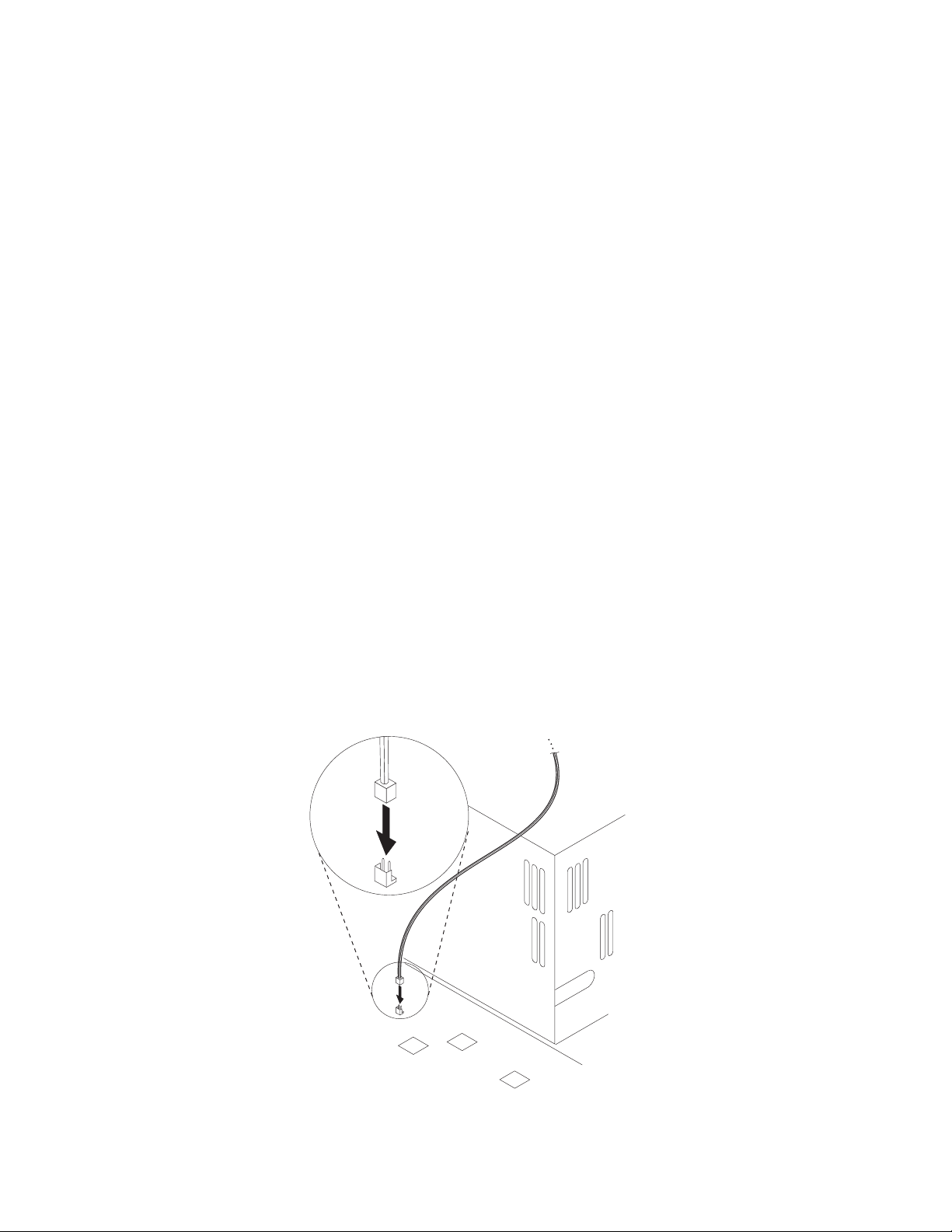
¹ Connect the planar connector to the system board as shown in
Figure 2-1. If you are using the two-connector cable, part number
42H2397, this connector has two pins. If you are using the
three-connector cable, part number 76H7254, this connector has three
pins.
¹ Connect the signal connector to your adapter at P5 as shown at number
2 in Figure 2-2 on page 2-3.
¹ If you are using the three-connector cable, part number 76H7254,
connect the power connector to the adapter at P4 as shown at number 3
in Figure 2-2 on page 2-3.
Otherwise, connect the power supply cable marked P9 or P12 to the
adapter at P4. See number 3 in Figure 2-2 on page 2-3.
Figure 2-1. Wake on LAN Signal Connector on the System Board
2-2 IBM Token-Ring PCI Family Adapter
Page 19
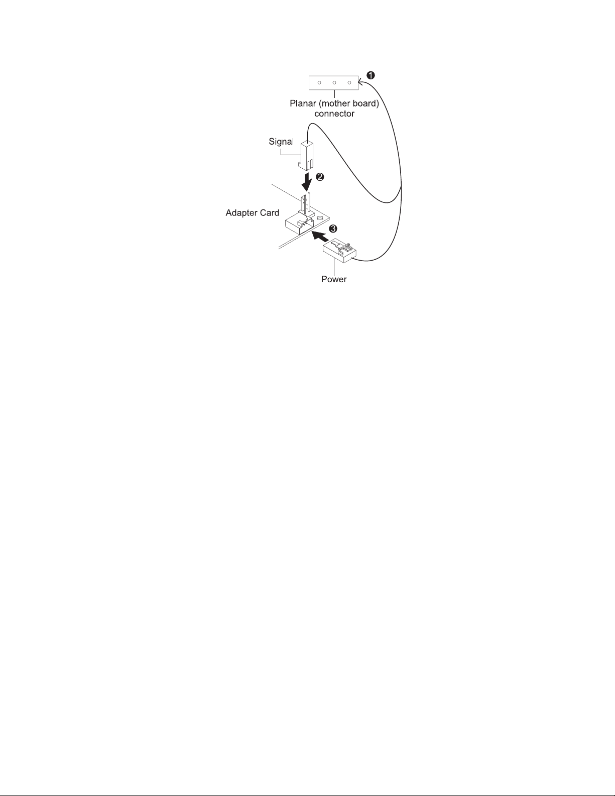
Figure 2-2. Connecting Cables to the adapter
3 Ensure that the adapter is secure in the PCI slot with retaining screw or other
bracket lockdown mechanism.
4 Re-install all removed covers.
5 Connect the Token-Ring cable to the adapter and to the network. See
“Adapter Cable” on page 2-4.
6 Re-connect all cables to your computer and then connect the power cord.
Follow all safety instructions.
Note: In the U.K., by law, the power cord must be connected before the
telephone line cable.
7 Installation is now complete. Go to Chapter 3, “Software Installation” on
page 3-1.
Installing Wake on LAN Cables for IBM 16/4 Token-Ring PCI
Adapter 2 with Wake on LAN
1 Connect the 7-pin end of the cable (P/N 30L6390) to your adapter at the
opposite end from the adapter bracket.
2 Connect the other ends of the cable to the system board. These connectors
go to the following system board connections:
¹ Black, yellow, and red cable to the motherboard connector labeled LAN
Wake.
¹ Blue, white, and green cable to the motherboard connector labeled Alert.
3 Ensure that the adapter is secure in the PCI slot with retaining screw or other
bracket lockdown mechanism.
4 Re-install all removed covers.
Chapter 2. Installing the Adapter Hardware 2-3
Page 20

5 Connect the Token-Ring cable to the adapter and to the network. See
“Adapter Cable” on page 2-4.
6 Re-connect all cables to your computer and then connect the power cord.
Follow all safety instructions.
Note: In the U.K., by law, the power cord must be connected before the
telephone line cable.
7 Installation is now complete. Go to Chapter 3, “Software Installation” on
page 3-1.
Installing Your Adapter without the Wake on LAN Feature
1 Ensure that the adapter is secure in the PCI slot with retaining screw or other
bracket lockdown mechanism.
2 Re-install all removed covers.
3 Connect the Token-Ring cable to the adapter and to the network. See
“Adapter Cable.”
Adapter Cable
4 Re-connect all cables to your computer and then connect the power cord.
Follow all safety instructions.
Note: In the U.K., by law, the power cord must be connected before the
telephone line cable.
5 Installation is now complete. Go to Chapter 3, “Software Installation” on
page 3-1.
To connect your adapter to a Token-Ring network, you will need one of the cables
illustrated in Figure 2-3 on page 2-5. Cables are not included in the package. The
network end of the cable must be compatible with the network faceplate or other
device to which the adapter will be connected.
Note: No more than one data cable may be connected to the adapter at a time.
2-4 IBM Token-Ring PCI Family Adapter
Page 21
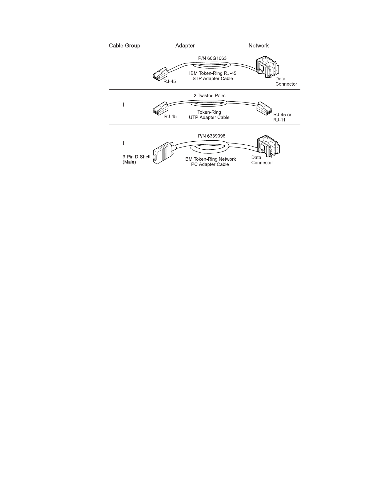
Figure 2-3. STP and UTP Cables
IBM 16/4 Token-Ring PCI Adapter 2 and IBM 16/4 Token-Ring PCI Adapter 2 with
Wake on LAN can use any of these cables.
IBM High-Speed 100/16/4 Token-Ring PCI Adapter must use cable II (category 5 or
better) or III. You cannot use cable I or the combination of P/N 60G1066 with cable
III.
Chapter 2. Installing the Adapter Hardware 2-5
Page 22

2-6 IBM Token-Ring PCI Family Adapter
Page 23

Chapter 3. Software Installation
1 Get the latest level of LAN driver updates for your operating system to ensure
that your code is at the latest level.
2 Be sure that your IBM Token-Ring PCI Family Adapter has already been
installed in your computer. If it has not, follow the instructions in Chapter 2,
“Installing the Adapter Hardware” on page 2-1.
3 Get the driver for your environment. There are three places to find the driver.
We recommend the first one listed here. All three methods will place the
driver in a directory according to the structure in Table 3-1.
¹ Method A: Get the driver from a software package on the IBM
Networking Hardware Division home page on the Web. This will ensure
that you get the latest driver. Go to x:\web\essmain.htm (where x is your
CD-ROM drive). Select your adapter from the section IBM Networking Web
site - current information. Select Downloads and choose the
appropriate software package for your environment. Execute the package
to expand the files. The driver will be in the directory listed in Table 3-1.
Note: You can also access the Web site directly at
www.networking.ibm.com/support
¹ Method B: Use the driver shipped on this CD-ROM directly with your
network operating system’s installation software. Note the directory
containing the driver (see Table 3-1).
¹ Method C: Get the driver from a software package shipped on this
CD-ROM. Point your Web browser to x:\web\essmain.htm (where x is
your CD-ROM drive). Select your adapter from the section CD-ROM -
release date information. Select Downloads and choose the
appropriate software package for your environment. Execute the package
to expand the files. The driver will be in the directory listed in Table 3-1.
4 Install the driver. Use Table 3-2 on page 3-2 to find the location of the
installation instructions for your environment. It is recommended that you
install the latest service pack for your operating environment before installing
the adapter software.
Table 3-1. Driver File Directory Structure
Operating System Directory
Windows 9x \ (root)
Windows NT \ (root)
Novell NetWare Server and Client \NOVELL\NETWARE
Novell NetWare DOS Requester (16-bit) \NOVELL\DOS
OS/2 \ (root)
DOS \DOS
Copyright IBM Corp. 1998 3-1
Page 24

Table 3-2. Installation Instructions
Environment Page
DOS with Windows Version 3.1x
IBM LAN Client See
Adapter Features
NetWare Requester 3-18
DOS LAN Services 3-17
IBM TCP/IP for DOS (Version 2.1) 3-17
DOS (without Windows)
IBM LAN Client See
Adapter Features
NetWare Requester 3-18
DOS LAN Services 3-17
IBM TCP/IP for DOS (Version 2.1) 3-17
NetWare Requester 3-18
NDIS2 3-17
IBM LAN Client See
Adapter Features
OS/2
OS/2 (MPTS) 3-12
NetWare Requester 3-15
OS/2 Warp Connect or Server 3-14
NetWare Server
NetWare Server Version 3.12 3-3
NetWare Server Version 4.11 3-7
Novell Client 3-11
Windows 32-bit
NT 3.51 3-20
NT 4.0 3-22
Windows 95 3-24
Windows 98 3-29
Remote Unattended Installation (Windows NT, Windows
95, Windows 98)
Novell IntranetWare Client for Windows NT 3-33
Novell Client for Windows 95 3-34
3-32
IBM Token-Ring
publication
IBM Token-Ring
publication
IBM Token-Ring
publication
3-2 IBM Token-Ring PCI Family Adapter
Page 25

Novell NetWare 3.12 Server
Before you start this installation, get the latest level of LAN driver updates for
NetWare 3.12 from Novell’s support Web site at support.novell.com. You will install
them during the following procedure.
If the Novell NetWare server is not installed on your machine, use the following
instructions. If it is installed, go to the instructions in “Server Driver Installation in
Existing NetWare 3.12 Server” on page 3-5.
Server Driver Installation in New NetWare 3.12 Server
Changes from the usual NetWare installation are necessary because this driver is
written to a new specification level that requires new NetWare loadable modules
(NLMs). The installation program is not aware of this, though, and these NLMs
must be loaded during installation of the server device driver and after the server
installation.
1 Create a diskette containing the extracted files from the NETWAREP.EXE
package file on the IBM Token-Ring PCI Family Adapter CD-ROM.
2 Refer to Novell’s
Follow the procedure for the installation of Novell NetWare 3.12 until the
section titled “Load LAN Drivers” is next.
Installation and Upgrade
manual for installation instructions.
3 Insert the diskette that you created in step 1 into drive A. Enter the following
commands at the server prompt:
LOAD A:\NOVELL\NETWARE\NBI31X.NLM
LOAD A:\NOVELL\NETWARE\MSM31X.NLM
LOAD A:\NOVELL\NETWARE\TOKENTSM.NLM
Note: A message referring to
before installation of Novell patches. It is for information only, and can be
ignored.
protected-mode BIOS access
might appear
4 Load the server device driver. Enter the following command at the server
prompt:
LOAD X:\NOVELL\NETWARE\IBMTRPO.LAN DATARATE=M16
It is recommended for servers that the DataRate be set to M16 or M4, and
clients be set to Auto. If your network is operating at 100 Mbps, this
parameter is ignored. The default is Auto.
Note: See Appendix E, “Novell NetWare Server and LAN Client Driver
Parameters” for a complete list of parameters that can be specified in the
LOAD IBMTRPO command in the AUTOEXEC.NCF file.
5 Follow the instructions in the Novell manual, beginning with “Bind the Protocol
to the LAN Driver” and continue until you are in the File Server
STARTUP.NCF File panel.
6 In addition to the instructions in the Novell manual, add the following line to
STARTUP.NCF:
Set Minimum Packet Receive Buffers = 48
Chapter 3. Software Installation 3-3
Page 26

Note: Increase the minimum packet receive buffers by 48 for each additional
adapter that is installed.
7 Perform the instructions in “Create an AUTOEXEC.NCF file” in the Novell
manual. Add the following lines to the AUTOEXEC.NCF file immediately after
the IPX INTERNAL NET statement (replace C:\SERVER.312\ with the location of
the NetWare server program):
LOAD C:\SERVER.312\NBI31X.NLM
LOAD C:\SERVER.312\MSM31X.NLM
LOAD C:\SERVER.312\TOKENTSM.NLM
LOAD C:\SERVER.312\IBMTRPO.LAN NAME=IBMLS1 DATARATE=M16
BIND IPX TO IBMLS1 NET=<unique net number>
Make sure that the line containing IBMTRPO.LAN has the complete path
name.
Notes:
a. See Appendix E, “Novell NetWare Server and LAN Client Driver
Parameters” for a complete list of parameters that you can specify on the
LOAD IBMTRPO command in the AUTOEXEC.NCF file.
b. If you experience any problems after loading the Novell NLM files, contact
Novell to ensure that you have the current version of these files.
Press Esc and answer Yes to save the new file to disk. Press Esc again to
return to the server console.
8 Shut down your server by entering down and then entering exit from the
server prompt.
9 Make sure that the diskette you created in step 1 is inserted in drive A. Enter
the following commands at the server prompt. You might be prompted to
perform a file overwrite; it is OK to overwrite these files.
COPY A:\NOVELL\NETWARE\NBI31X.NLM C:\SERVER.312
COPY A:\NOVELL\NETWARE\MSM31X.NLM C:\SERVER.312
COPY A:\NOVELL\NETWARE\TOKENTSM.NLM C:\SERVER.312
COPY A:\NOVELL\NETWARE\IBMTRPO.LAN C:\SERVER.312
COPY A:\NOVELL\NETWARE\IBMTRPO.LDI C:\SERVER.312
10 Go to the Novell server directory and enter server at the DOS prompt to
restart the server.
11 Install the patches obtained earlier now. Make sure to select the v3.31 ODI
LAN Updates for Hardware if given the opportunity.
12 Installation is now complete.
Check for the following conditions to determine whether the adapter is
working correctly and whether installation has been completed successfully:
¹ The device driver files are loading successfully. There are no error
messages.
¹ The adapter LEDs indicate normal operation: green ON, amber OFF.
See “Understanding the Adapter LEDs and Labels” on page 4-3.
If you experience problems, go to Chapter 4, “Problem Solving.”
3-4 IBM Token-Ring PCI Family Adapter
Page 27

For information concerning NetWare server error messages, see Appendix F,
“Novell NetWare Server and LAN Client Driver Messages.”
Server Driver Installation in Existing NetWare 3.12 Server
If Novell NetWare is already installed in your computer, perform the following steps
to install the adapter server device driver.
1 Create a diskete containing the extracted files from the NETWAREP.EXE file
on the IBM Token-Ring PCI Family Adapter CD-ROM.
2 Install the patches obtained earlier now. Make sure to select the v3.31 ODI
LAN Updates for Hardware if given the opportunity. Return to the server
console when the installation is complete.
3 Make sure that the diskette you created in step 1 is inserted in drive A. Enter
the following commands at the server prompt. You might be prompted to
perform a file overwrite; it is OK to overwrite these files.
COPY A:\NOVELL\NETWARE\NBI31X.NLM C:\SERVER.312
COPY A:\NOVELL\NETWARE\MSM31X.NLM C:\SERVER.312
COPY A:\NOVELL\NETWARE\TOKENTSM.NLM C:\SERVER.312
COPY A:\NOVELL\NETWARE\IBMTRPO.LAN C:\SERVER.312
COPY A:\NOVELL\NETWARE\IBMTRPO.LDI C:\SERVER.312
Note: If you experience any problems after loading the Novell NLM files,
check the Novell Web site to ensure that you have the current version of
these files.
4 In the directory where Novell is installed on your hard disk, enter server at
the DOS prompt to start the server.
5 At the server console prompt, enter load install.
6 From the Installation Options menu, select System Options and press Enter.
7 Select Edit STARTUP.NCF File and press Enter. Add the following line to
the STARTUP.NCF file:
Set Minimum Packet Receive Buffers = 48
Note: Increase the minimum packet receive buffers by 48 for each additional
adapter that is installed.
8 Press Esc and then answer Yes to save changes to the STARTUP.NCF file.
9 Select Edit AUTOEXEC.NCF File and press Enter. Edit this file and, after
the IPX internal net statement, include the following statements. (Replace
C:\SERVER.312\ with the location of the NetWare server program.)
It is recommended for servers that the DataRate be set to M16 or M4, and
clients be set to Auto. If your system is 100 MB, this parameter is ignored.
The default is Auto.
LOAD C:\SERVER.312\NBI31X
LOAD C:\SERVER.312\MSM31X
LOAD C:\SERVER.312\TOKENTSM
LOAD C:\SERVER.312\IBMTRPO NAME=IBMLS1 DATARATE=M16
BIND IPX TO IBMLS1 NET=<unique net number>
Chapter 3. Software Installation 3-5
Page 28

See Appendix E, “Novell NetWare Server and LAN Client Driver Parameters”
for a complete list of parameters that can be specified on the LOAD IBMTRPO
command in the AUTOEXEC.NCF file.
Press Esc and then answer Yes to save the new file to disk. Press Esc
again to return to the server console.
10 Shut down your server by entering down and then entering exit from the
server prompt.
11 Enter server to restart the server.
12 Installation is now complete. Shut down and restart your computer for all
changes to take effect.
Check for the following conditions to determine whether the adapter is
working correctly and whether installation has been completed successfully:
¹ The device driver files are loading successfully. There are no error
messages.
¹ The adapter LEDs indicate normal operation: green ON, amber OFF.
See “Understanding the Adapter LEDs and Labels” on page 4-3.
If you experience problems, go to Chapter 4, “Problem Solving.”
For information concerning NetWare server error messages, see Appendix F,
“Novell NetWare Server and LAN Client Driver Messages.”
3-6 IBM Token-Ring PCI Family Adapter
Page 29

Novell NetWare 4.11 Server
Before you start this installation, get the latest level of patches from Novell and
install them. The current level is IntraNetWare Support Pack Version 5.0 from the
Novell support Web site at http://support.novell.com.
If Novell NetWare is not installed on your machine, use the following instructions. If
it is installed, follow the instructions in “Server Driver Installation in Existing
NetWare 4.11 Server” on page 3-8.
Server Driver Installation in New NetWare 4.11 Server
Changes from the usual NetWare installation are necessary because this driver is
written to a new specification level that requires new NetWare loadable modules
(NLMs). The installation program is not aware of this, though, and these NLMs
must be loaded during installation of the server device driver and after the server
installation.
Note: A message referring to protected-mode BIOS access might appear before
installation of Novell patches. It is for information only, and can be ignored.
1 Create a diskette containing the extracted files from the NETWAREP.EXE
package file on the IBM Token-Ring PCI Family Adapter CD-ROM.
2 When you see INSTALL Found the following : PCI LAN Controller
xxxx.xxxx.xxxx press Enter. Then press the Insert (INS) key to install the
unlisted driver.
3 Press ALT-ESC to toggle to the server console, and enter the following
LOAD statements (make sure that the diskette that you created in step 1 is
inserted in drive A):
LOAD A:\NOVELL\NETWARE\MSM.NLM
LOAD A:\NOVELL\NETWARE\TOKENTSM.NLM
4 Press ALT-ESC to toggle back to the INSTALL panel.
5 Press F3 on the next panel to specify A:\NOVELL\NETWARE as the directory
path.
Press Enter then follow the instructions on the panel to complete the
installation of the driver. If you need to make any custom configuration
changes to the driver, do so at this time.
6 Follow the instructions in the Novell manual
In addition to the instructions in the manual, add the following lines to the
AUTOEXEC.NCF file immediately after the IPX INTERNAL NET statement (if
necessary, replace C:\NWSERVER with the location of the SERVER.EXE
executable):
Create an AUTOEXEC.NCF file
.
LOAD C:\NWSERVER\NBI.NLM
LOAD C:\NWSERVER\MSM.NLM
LOAD C:\NWSERVER\TOKENTSM.NLM
LOAD C:\NWSERVER\IBMTRPO.LAN NAME=IBMLS1 DATARATE=M16
Note: There will be existing LOAD and BIND IPX statements in the
AUTOEXEC.NCF. Delete the LOAD statement (we have replaced it with
stated LOAD C:\NWSERVER\IBMTRPO.LAN statement). Also, make any
Chapter 3. Software Installation 3-7
Page 30

needed modifications to the existing BIND IPX statement (refer to the
the Protocol to the LAN Driver
information).
See Appendix E, “Novell NetWare Server and LAN Client Driver Parameters”
on page E-1 for a complete list of parameters that can be specified on the
LOAD IBMTRPO command in the AUTOEXEC.NCF file.
section of the Novell manual for additional
Bind
7 Press ESC and answer YES to save the new file to disk. Press ESC again to
return to the server console.
8 Type the following commands from the server prompt to shut down the server
and exit to DOS: down, then exit.
9 Perform the following COPY commands, making sure that the diskette that
you created in step 1 is inserted in drive A. Note that it will prompt you at
each of the following files to ask if you want to perform a file overwrite; it is
OK to overwrite these files.
COPY A:\NOVELL\NETWARE\NBI.NLM C:\NWSERVER
COPY A:\NOVELL\NETWARE\MSM.NLM C:\NWSERVER
COPY A:\NOVELL\NETWARE\TOKENTSM.NLM C:\NWSERVER
COPY A:\NOVELL\NETWARE\IBMTRPO.LAN C:\NWSERVER
COPY A:\NOVELL\NETWARE\IBMTRPO.LDI C:\NWSERVER
10 Go to the Novell server directory and enter server at the DOS prompt to
restart the server.
11 Install the latest available Novell patches for NetWare 4.11 now. Make sure to
select the Version 3.31 ODI LAN Updates for Hardware if given the
opportunity.
12 Issue the following commands from the server prompt to bring the server
down, then reboot it: down, then restart server.
13 Installation is now complete. Check for the following conditions to determine
whether the adapter is working correctly and whether installation has been
completed successfully:
¹ The device driver files are loading successfully. There are no error
messages.
¹ The adapter LEDs indicate normal operation. green ON, amber OFF. See
“Understanding the Adapter LEDs and Labels” on page 4-3.
If you experience problems, go to Chapter 4, “Problem Solving.”
For information concerning NetWare server error messages, see Appendix F,
“Novell NetWare Server and LAN Client Driver Messages.”
Server Driver Installation in Existing NetWare 4.11 Server
If Novell NetWare is already installed in your computer, perform the following steps
to install the adapter server device driver.
Note: If you are altering the configuration of a previously loaded adapter, unload
that adapter before proceeding with these instructions.
3-8 IBM Token-Ring PCI Family Adapter
Page 31

1 Create a diskette containing the extracted files from the NETWAREP.EXE file
on the IBM Token-Ring PCI Family Adapter CD-ROM.
2 Be sure that your IBM Token-Ring PCI Family Adapter has already been
installed in your computer. If it has not, follow the instructions in Chapter 2,
“Installing the Adapter Hardware” on page 2-1.
3 Install the latest available Novell patches for NetWare 4.11. Make sure to
select the Version 3.31 ODI LAN Updates for Hardware if given the
opportunity. Return to the server console when the installation is complete.
4 Issue the following commands from the server prompt to bring the server
down, then restart it again:
down
restart server
5 Check to see if the device driver is loaded. If it is, unload it using the
following command: unload ibmtrpo
6 Type load install on the server.
7 Select Driver Options.
8 Select Configure Network Drivers.
9 Select Select Drivers.
10 On the next panel, press the Insert (INS) key to install the unlisted driver.
11 Insert the diskette that you created in step 1; press F3 on the next panel and
specify the path A:\NOVELL\NETWARE.
12 Follow the instructions on the panels to complete the installation of the driver.
If you need to make any custom configuration changes to the driver, do so at
this time.
13 Follow the instructions in the Novell manual
In addition to the instructions in the manual, add the following lines to the
AUTOEXEC.NCF file, immediately after the IPX INTERNAL NET statement (if
necessary, replace C:\NWSERVER with the actual location of the
SERVER.EXE executable):
LOAD C:\NWSERVER\NBI.NLM
LOAD C:\NWSERVER\MSM.NLM
LOAD C:\NWSERVER\TOKENTSM.NLM
LOAD C:\NWSERVER\IBMTRPO.LAN NAME=IBMLS1 DATARATE=M16
Create an AUTOEXEC.NCF file
.
Note: There will be existing LOAD and BIND IPX statements in the
AUTOEXEC.NCF. Delete the LOAD statement (we have replaced it with the
stated LOAD C:\NWSERVER\IBMTRPO.LAN statement).
Also, make any needed modifications to the existing BIND IPX statement
(refer to the
for additional information).
Chapter 3. Software Installation 3-9
Bind the Protocol to the LAN Driver
section of the Novell manual
Page 32

See Appendix E, “Novell NetWare Server and LAN Client Driver Parameters”
for a complete list of parameters that can be specified on the LOAD IBMTRPO
command in the AUTOEXEC.NCF file.
14 Press ESC and answer YES to save the new file to disk. Press ESC again to
return to the server console.
15 Type the following commands from the server prompt to shut down the server
and exit to DOS: down, and then exit.
16 Perform the following COPY commands, making sure that the diskette that
you created in step 1 is inserted in drive A. Note that it will prompt you at
each of the following files to ask if you want to perform a file overwrite; it is
OK to overwrite these files.
COPY A:\NOVELL\NETWARE\NBI.NLM C:\NWSERVER
COPY A:\NOVELL\NETWARE\MSM.NLM C:\NWSERVER
COPY A:\NOVELL\NETWARE\TOKENTSM.NLM C:\NWSERVER
COPY A:\NOVELL\NETWARE\IBMTRPO.LAN C:\NWSERVER
COPY A:\NOVELL\NETWARE\IBMTRPO.LDI C:\NWSERVER
17 Go to the Novell server directory and enter server at the DOS prompt to
restart the server.
18 Installation is now complete. Check for the following conditions to determine
whether the adapter is working correctly and whether installation has been
completed successfully:
¹ The device driver files are loading successfully. There are no error
messages.
¹ The adapter LEDs indicate normal operation. green ON, amber OFF. See
“Understanding the Adapter LEDs and Labels” on page 4-3.
If you experience problems, go to Chapter 4, “Problem Solving.”
For information concerning NetWare server error messages, see Appendix F,
“Novell NetWare Server and LAN Client Driver Messages.”
3-10 IBM Token-Ring PCI Family Adapter
Page 33

Novell Client DOS/Windows 3.1x
1 Download Novell Client DOS/Windows 3.1x Version 2.5 or higher from
Novell’s Web site (http://support.novell.com). Unzip the downloaded file to a
directory on your computer.
2Exit Windows.
3 From a DOS prompt, go to the directory where you put the file. Run
INSTALL.EXE.
4 Select Yes or No to respond to the Novell License Agreement.
5 Select Novell Client Windows Support and Work Station Manager 3.X.
Press F10 to save and continue.
6 Select 32-bit LAN Drivers and press F10 to save and continue.
7 Select USER SPECIFIED 32-Bit Driver and press Enter. Insert the CD-ROM
or the diskette containing the device drivers into the appropriate drive. Enter
the path to the 32-bit ODI driver: x:\novell\netware where x is your CD-ROM
drive letter. The panel should say
IBM Token-Ring PCI Family Adapter
Press Enter, configure the parameters, and press F10 to save and continue.
8 At the panel entitled Installation Configuration Summary, confirm that the
values are what you selected, and press F10 to save and continue.
9 The files will be copied at this point.
10 Installation is now complete.
11 Reboot your computer and start Windows to connect to and login to your
server.
12 Check for the following conditions to determine whether the adapter is
working correctly and whether installation has been completed successfully:
¹ The device driver files are loading successfully. There are no error
messages.
¹ The adapter LEDs indicate normal operation. green ON, amber OFF. See
“Understanding the Adapter LEDs and Labels” on page 4-3.
If you experience problems, go to Chapter 4, “Problem Solving.”
Chapter 3. Software Installation 3-11
Page 34

OS/2 NDIS 2 Device Driver Using MPTS
MPTS is the Multiple Protocol Transport Services.
1 When updating an existing device driver, error message X100035, which
indicates that the driver could not be installed and the previous version could
not be restored, can be prevented by performing the following steps before
beginning the update. This is particularly useful when the existing driver was
installed from the adapter CD-ROM.
¹ From an OS/2 window, go to the drive where OS/2 is installed. Change to
the IBMCOM subdirectory (where x is your drive letter):
x:
cd \ibmcom
¹ Enter the following two commands:
attrib -r ibmtrp.* /s
attrib -r la1*.msg
2 Start MPTS by performing either of the following actions:
¹ From the OS/2 desktop, double-click the MPTS icon.
¹ From an OS/2 window, go into the IBMCOM subdirectory and enter mpts
at the OS/2 prompt.
3 Select OK on the MPTS logo panel.
4 Select Install. You will be prompted for the source of the .NIF file. Enter the
path to the driver directory. Select OK once the Installation Complete
message appears. You will return to the main menu.
5 Select Configure in the MPTS dialog box.
6 On the Configure panel, make sure that LAN adapters and protocols is
preselected and then select Configure at the bottom of the panel.
7 In the Configuration panel, in the Network Adapters group box, select IBM
Token-Ring PCI Family Adapter (IBMTRP.OS2) and select ADD.
Note: You can edit parameter settings for this adapter. Highlight your
adapter in the Current Configuration list box and select Edit.
8 In the Protocols list box, select the protocols used by your network
application. Highlight each protocol and select ADD. If you are not sure
which ones to use, select IBM IEEE 802.2 and IBM OS/2 NetBIOS protocol
drivers or ask your network administrator.
The protocol drivers you have selected will appear under the adapter driver
name in the Current Configuration list box.
Note: You can edit parameter settings for the protocols. Highlight a protocol
and select Edit.
9 Select OK when you have finished selecting and editing protocols in the
MPTS Configuration panel.
3-12 IBM Token-Ring PCI Family Adapter
Page 35

10 Select Close on the Configure panel.
11 Select Exit in the MPTS dialog box.
12 Select Exit on the Update CONFIG.SYS panel to update the CONFIG.SYS
file.
13 Select OK when you get the message that the CONFIG.SYS has been
successfully updated.
14 Select Exit on the Exiting MPTS panel.
15 Shut down and restart your computer to let the changes take effect.
Installation is now complete.
16 At system startup, check for the following conditions to determine whether the
adapter is working correctly and whether installation has been completed
successfully:
¹ The device driver files loaded successfully. There are no error
messages.
¹ The adapter LEDs indicate normal operation: green ON, amber OFF.
If you experience problems, go to Chapter 4, “Problem Solving.”
For information concerning NDIS driver error messages, see Appendix D,
“NDIS 2 Device Driver Messages.”
Chapter 3. Software Installation 3-13
Page 36

OS/2 NDIS 2 Device Driver Using Other Installation Programs
1 Insert the CD-ROM or the NDIS Drivers diskette into the appropriate drive.
2 Use your product documentation to install the driver (IBMTRP.OS2), which is
located in the root directory on both the CD-ROM and diskette.
3 Modify the parameters if needed. See Appendix C, “NDIS 2 Device Driver
Parameters.”
IBM TCP/IP for OS/2 and Warp Connect are examples of products that
provide driver installation programs.
4 Installation is now complete. Shut down and restart your computer for all
changes to take effect.
5 Check for the following conditions to determine whether the adapter is
working correctly and whether installation has been completed successfully:
¹ The device driver files load successfully. There are no error messages.
¹ The adapter LEDs indicate normal operation: green ON, amber OFF.
If you experience problems, go to Chapter 4, “Problem Solving.”
For information concerning NDIS driver error messages, see Appendix D,
“NDIS 2 Device Driver Messages.”
3-14 IBM Token-Ring PCI Family Adapter
Page 37

OS/2 Novell NetWare Requester
Before installation, copy IBMTRPO.SYS from the CD-ROM or the ODI Drivers and
LAN Client (A) diskette to the root directory containing your Novell NetWare
Requester source files.
1 Refer to the workstation basics and installation manuals from Novell to begin.
When a dialog box titled Requester Installation appears during the installation
process, continue with the following steps.
2 If you are installing the NetWare Requester on a workstation, select Edit
CONFIG.SYS and Copy All Files.... If the NetWare Requester is already
installed on the workstation and only a driver update is needed, then select
Only Edit CONFIG.SYS....
3 On the next panel, specify the name of the adapter driver: IBMTRPO.SYS.
4 When you get to the panel labeled “Copy ODI LAN Driver files,” select Copy
only the default driver.
5 Continue with the installation, following the instructions on the panels.
6 When Installation Complete appears in the Requester window, go to the
Configuration menu and select This workstation....
7 Select Edit to accept the default location for the NET.CFG file.
8 In the edit box titled Current NET.CFG File Contents, type the following lines:
link driver IBMTRPO
SLOT 10001
link support
BUFFERS 8 4096
Notes:
a. See Appendix G, “Novell NetWare DOS ODI Driver Parameters” for a
complete list of parameters that you can specify in the NET.CFG file.
b. To enable source routing, changes will have to be made to the
CONFIG.SYS file. Refer to Novell’s
instructions on how to enable source routing.
c. The lines in the NetWare Requester section of the CONFIG.SYS file must
be in a certain order. Do not reorder the lines in this section of
CONFIG.SYS. Refer to the Novell manuals for more information.
Workstation for OS/2
manual for
9 Select Save to complete the NetWare Requester installation.
10 Reboot the computer for the changes to take effect.
Note: To make changes in the NetWare Requester configuration,
double-click the Novell icon on the desktop. Double-click the Install icon in
the Novell window. Go to the Configuration and select This workstation....
Make sure that the correct NET.CFG is shown in the next dialog box and
select Edit. Edit the NET.CFG file in the edit box titled Current NET.CFG File
Contents. When the changes are complete, select Save. It is necessary to
reboot the computer in order to make the changes take effect.
Chapter 3. Software Installation 3-15
Page 38

11 Installation is now complete. Check for the following conditions to determine
whether the adapter is working correctly and whether installation has been
completed successfully:
¹ The device driver files loaded successfully. There are no error
messages.
¹ The adapter LEDs indicate normal operation: green ON, amber OFF.
If you experience problems, go to Chapter 4, “Problem Solving.”
For information concerning Novell NetWare server messages, see
Appendix F, “Novell NetWare Server and LAN Client Driver Messages.”
3-16 IBM Token-Ring PCI Family Adapter
Page 39

DOS NDIS 2
Note: It is recommended that you use LAN Client (Client32) whenever possible as
an efficient solution.
1 Insert the CD-ROM or the NDIS Drivers diskette into the appropriate drive.
2 Use your operating system documentation to install the driver (IBMTRP.DOS).
This driver is located in the \dos subdirectory on both diskette and the
CD-ROM.
3 Modify the parameters, if needed. See Appendix C, “NDIS 2 Device Driver
Parameters.”
Note: If you use Microsoft Windows for Workgroups and want to configure
the NetAddress parameter for the NDIS device driver, remember to enclose
the address in double quotes (""). The NetAddress parameter is used to set
a locally administered address for the adapter.
4 Installation is now complete. Shut down and restart your computer for all
changes to take effect.
5 Check for the following conditions to determine whether the adapter is
working correctly and whether installation has been completed successfully:
¹ The device driver files load successfully. There are no error messages.
If error messages are displayed or if you do not see messages that
indicate that the drivers have been installed, go to “Start of
Troubleshooting Process” on page 4-1.
¹ The adapter LEDs indicate normal operation: green ON, amber OFF.
If you experience problems, go to Chapter 4, “Problem Solving.”
For information concerning NDIS driver error messages, see Appendix D,
“NDIS 2 Device Driver Messages.”
Chapter 3. Software Installation 3-17
Page 40

DOS Novell NetWare Requester (16-bit)
Note: It is recommended that you use LAN Client (Client32) whenever possible as
an efficient solution.
The 16-bit DOS Novell NetWare Requester environment supports access to servers
running Novell NetWare 3.11 or higher.
To install the IBMTRPO.EXE ODI driver on a DOS computer, perform the following
steps:
Note: Consult your Novell NetWare documentation for instructions regarding how
to create the NetWare Client for DOS and MS Windows diskettes.
1 Create a diskette containing the extracted files from the DOSODIP.EXE file
on the IBM Token-Ring PCI Family Adapter CD-ROM.
2 Insert the NetWare Client for DOS and MS Windows Disk 1 into the
appropriate drive.
3 At the command prompt, type X:, where X is your drive letter, and then press
Enter.
4 Type install and then press Enter.
5 Follow the instructions as they appear. In step 5, select the driver for your
network board. Scroll down through Network Boards, highlight Other
Drivers; then press Enter.
6 Insert the CD-ROM or the diskette that you created in step 1 into the
appropriate drive. When prompted, specify the location to the chosen media
and press Enter. Specify the path as A:\NOVELL\DOS (or at
X:NOVELL\DOS for the CD-ROM version).
7 Highlight your adapter and press Enter.
8 At this time you can change the default parameters. When you finish making
any desired changes, press F10. Appendix G, “Novell NetWare DOS ODI
Driver Parameters” contains the parameters that can be configured in the
NET.CFG file.
9 Follow the instructions presented to finish the installation.
Note: If source routing is required, edit the STARTNET.BAT file that is in the
client directory (usually C:\NWCLIENT) and add the following line after the
IPXODI statement:
C:\NWCLIENT\ROUTE
10 Shut down and restart your computer for all changes to take effect.
11 Check for the following conditions to determine whether the adapter is
working correctly and whether installation has been completed successfully:
¹ The device driver files load successfully. There are no error messages.
If error messages are displayed or if you do not see messages that
3-18 IBM Token-Ring PCI Family Adapter
Page 41

indicate that the drivers have been installed, go to “Start of
Troubleshooting Process” on page 4-1.
¹ The adapter LEDs indicate normal operation: green ON, amber OFF.
If you experience problems, go to Chapter 4, “Problem Solving.”
Chapter 3. Software Installation 3-19
Page 42

Windows NT Version 3.51
The following procedure assumes that Windows NT 3.51 has already been installed
with networking support. It is highly recommended that you install Service Pack 5
from Microsoft before installing the driver.
1 Log on to Windows NT as an administrator.
2 From the Main program group within the Program Manager, find and
double-click the Control Panel icon.
3 In the Control Panel window, double-click the Network icon.
4 In the Network Setting, select Add Adapter.
5 In the Add Network Adapter dialog box, click the drop-down list for Network
Adapter Card. Scroll down the list and select <Other> Requires disk from
manufacturer. Then, select Continue.
6 Insert the CD-ROM or the diskette containing the device drivers into the
appropriate drive. When prompted, enter the path to the driver directory and
select OK.
7 Select OK to accept the drive and path information.
8 In the Select OEM Option dialog box, select IBM Token-Ring PCI Family
Adapter.
Several work-in-progress panels are displayed, indicating that the driver and
its supporting files are being copied to your computer’s hard disk.
9 The Network Control panel is displayed again. There should be an entry in
the Installed Adapter Cards list for each IBM Token-Ring PCI Family Adapter
found in the computer.
To change default values for a adapter, select that adapter in the Installed
Adapters list box, and then select Configure. Make the necessary changes
and select OK.
Note: Make sure that all of the appropriate protocols are installed to connect
to the network. Consult your network administrator if you are unsure of what
protocols need to be installed.
10 Select OK at the top right to complete the installation.
Note: If TCP/IP is installed as a protocol on the computer, you will now see
the TCP/IP configuration panel. Enter all necessary information and select
OK.
11 The following message will be displayed:
Your network settings have changed.
You will need to exit and restart Windows NT so that the new
settings can take effect.
Select Restart now in order to have Windows NT automatically restart your
computer.
3-20 IBM Token-Ring PCI Family Adapter
Page 43

12 Installation is now complete. You might need to reinstall Service Pack 5 due
to changes to your services or protocols during installation.
13 Check for the following conditions to determine whether the adapter is
working correctly and whether installation has been completed successfully:
¹ The device driver files loaded successfully.
¹ There are no error messages logged for the IBMTRP service in the Event
Viewer.
¹ The adapter LEDs indicate normal operation: green ON, amber OFF.
If you experience problems, go to Chapter 4, “Problem Solving.”
Chapter 3. Software Installation 3-21
Page 44

Windows NT Version 4.0
The following procedure assumes that Windows NT 4.0 has already been installed
with networking support. It is highly recommended that you install Service Pack 3 or
higher from Microsoft before installing the driver.
1 Log on to Windows NT as an administrator.
2 Select Start 5 Settings 5 Control Panel.
3 From the Control Panel window, double-click the Network icon.
4 Select the Adapters tab.
5Select Add.
6 You will see a dialog box that includes a list of adapters. Select Have
Disk....
7 Insert the CD-ROM or the diskette containing the device drivers into the
appropriate drive. When prompted, enter the path to the root directory of the
CD-ROM or diskette and select OK.
8 In the Select OEM Option dialog box, select IBM Token-Ring PCI Family
Adapter and then select OK.
Several work-in-progress panels are displayed, indicating that the driver and
its supporting files are being copied to your computer’s hard disk.
9 The Network Control panel is displayed again. There should be an entry in
the Installed Adapters list for each IBM Token-Ring PCI Family Adapter found
in the computer.
To change default values for a adapter, select that adapter on the Network
Adapters list, and then select Properties. Make the necessary changes and
select OK.
Note: Make sure that all of the appropriate protocols are installed to connect
to the network. Consult your network administrator if you are unsure of what
protocols need to be installed.
10 Select Close to complete the installation.
Note: If TCP/IP is installed as a protocol on the computer, you will now see
the TCP/IP configuration panel. Enter all necessary information and select
OK.
11 The following message will be displayed:
Your network settings have changed.
You will need to exit and restart Windows NT so that the new
settings can take effect.
Select Yes in order to have Windows NT automatically restart your computer.
12 Installation is now complete. You might need to reinstall the Service Pack
due to changes to your services or protocols during installation.
3-22 IBM Token-Ring PCI Family Adapter
Page 45

13 Check for the following conditions to determine whether the adapter is
working correctly and whether installation has been completed successfully:
¹ The device driver files loaded successfully.
¹ There are no error messages logged for the IBMTRP service in the Event
Viewer.
¹ The adapter LEDs indicate normal operation: green ON, amber OFF.
If you experience problems, go to Chapter 4, “Problem Solving.”
Chapter 3. Software Installation 3-23
Page 46

Windows 95
There are two different versions of Windows 95 in distribution: the retail release,
which can be purchased by individuals, and the OEM Service Release 2 (OSR2),
which is found on most computer system preloads. To find out if you are running
the OSR2 release, select Start 5 Settings 5 Control Panel, and then double-click
the System icon. Look at the version number under the text Microsoft Windows 95.
¹ If the number is 4.00.950a or 4.00.950, you are using the retail release of
Windows 95.
¹ If the number is 4.00.950 B, you are using the OSR2 release of Windows 95.
Make sure that you refer to the appropriate installation section for the version of
Windows 95 that you are using.
Before beginning installation, shut down the computer. Make sure that the operating
system is correctly shut down and then switch off the power and disconnect the
power cable from the power source.
If Windows 95 Retail is Already Installed
1 When you boot Windows 95, it will detect the new hardware and bring up a
dialog box to allow a choice of drivers. Select Driver from disk provided by
hardware manufacturer and then select OK.
2 Insert the CD-ROM or the NDIS Drivers diskette into the appropriate drive.
When prompted, enter the path to the driver directory and select OK.
Note: Some of the files on the diskette are located in the DOS subdirectory.
If necessary, you will have to supply this subdirectory to get additional files
copied onto your computer.
3 At this point, Windows 95 might prompt you for network names. Type your
computer’s name and workgroup. Consult your system administrator if you
do not know this information. Select OK to continue.
4 The driver files will be copied. Windows might prompt you for the Windows 95
CD-ROM in order to install its default network protocols and services. Make
sure that the location of your Windows 95 installation files (for example, D:\ or
D:\WIN95 or C:\WINDOWS\CATROOT) appears in the entry and select OK.
5 After the files have been copied, a dialog box will display the following
message:
To finish setting up your new hardware, you must
restart your computer. Do you want to restart your computer now?
Remove the diskette or CD-ROM from the computer and select Yes.
6 Installation is now complete.
Check for the following conditions to determine whether the adapter is
working correctly and whether installation has been completed successfully:
¹ The device driver files loaded successfully.
¹ The device manager (System control panel applet) reports that the device
is working correctly.
3-24 IBM Token-Ring PCI Family Adapter
Page 47

¹ The adapter LEDs indicate normal operation: green ON, amber OFF.
If you experience problems, go to Chapter 4, “Problem Solving.”
If Windows 95 OSR2 Is Already Installed
1 When you boot Windows 95, it will detect the new hardware and display the
Update Device Driver Wizard dialog which displays the following message:
This wizard will complete the
installation of: PCI Token Ring Controller.
Insert the adapter CD-ROM or the NDIS Drivers diskette containing the
device drivers into the appropriate drive.
2 Insert the CD-ROM or the NDIS Drivers diskette into the appropriate drive.
When prompted, enter the path to the driver directory and select OK.
Note: Some of the files on the diskette are located in the DOS subdirectory.
If necessary, you will have to supply this subdirectory to get additional files
copied onto your computer.
3 At this point, Windows 95 might prompt you for network names. Type in your
computer’s name and workgroup. Consult your system administrator if you
do not know this information. Select OK to continue.
4 The driver files will be copied at this point. Windows might prompt you for the
Windows 95 CD-ROM in order to install its default network protocols and
services. Make sure that the location of your Windows 95 installation files (for
example, D:\ or D:\WIN95 or C:\WINDOWS\CATROOT) appears in the entry
and select OK. You might also be prompted again for the location of the
driver files. Enter the appropriate location again as described previously.
5 After the files have been copied, a dialog box will display the following
message:
To finish setting up your new hardware, you must
restart the computer. Do you want to restart your computer now?
Remove the driver diskette or CD-ROM from the computer and select Yes.
6 Installation is now complete.
Check for the following conditions to determine whether the adapter is
working correctly and whether installation has been completed successfully:
¹ The device driver files loaded successfully.
¹ The Device Manager (System control panel applet) reports that the
device is working correctly.
¹ The adapter LEDs indicate normal operation: green ON, amber OFF.
If you experience problems, go to Chapter 4, “Problem Solving.”
Chapter 3. Software Installation 3-25
Page 48

First-Time Installation of Windows 95 with the IBM Token-Ring PCI
Family Adapter
If Windows 95 is installed on a computer with the IBM Token-Ring PCI Family
Adapter already installed, Windows 95 will detect the adapter, but will not install
any drivers. Use the following procedure to correct the problem.
1 Insert the NDIS Drivers diskette or the CD-ROM into the appropriate drive.
2 Select Start Settings 5 Control Panel. This will display the Control Panel.
3 In the Control Panel window, double-click the System icon.
4 Select the Device Manager tab.
5 Within the Device Manager, expand the Other Devices section by selecting
the + icon that appears to the left of the words Other Devices. Select the
entry for PCI Token Ring Controller and then select Properties.
6 Select the Driver tab. Depending on which version of Windows 95 you have
(retail or OSR2), this dialog will look different. If the Driver properties sheet
has a Change Driver button, continue with “Continuing Installation of the
Driver without the Device Wizard.” If, however, the properties sheet has an
Update Driver button instead, continue with “Continuing Installation of the
Driver Using the Update Device Driver Wizard” on page 3-27.
Continuing Installation of the Driver without the Device Wizard
1 Select the Change Driver button to display the Select Hardware Type dialog.
Select Network adapters and select OK.
2 Select Have Disk from the Select Device dialog. Type the letter of your
CD-ROM drive and select OK.
Note: Some of the files on the diskette are located in the DOS subdirectory.
If necessary, you will have to supply this subdirectory to get additional files
copied onto your computer.
3 Windows will display a list of compatible devices. Make sure that your adapter
is selected and then select OK.
4 Windows will return to the PCI Token Ring Controllers Properties dialog box.
Select OK to continue.
5 At this point, Windows might prompt you for network names. Type your
computer’s name and workgroup. Consult your system administrator if you
do not know this information. Select OK to continue.
The driver files will be copied at this point. Windows might prompt you for the
Windows 95 CD-ROM in order to install default network protocols and
services. Make sure that the location of your Windows 95 installation files (for
example, D:\ or D:\WIN95 or C:\WINDOWS\CATROOT) appears in the entry
and select OK.
6 If Windows 95 displays a dialog that warns you that the PCI Token-Ring
Controller has a ROM, ignore the message and select Test to continue.
3-26 IBM Token-Ring PCI Family Adapter
Page 49

7 Select OK in the Device Manager.
8 Remove the driver diskette or CD-ROM. Reboot your computer (select Start 5
Shut Down and select Restart the computer).
9 Installation is now complete.
Continuing Installation of the Driver Using the Update Device
Driver Wizard
1 Select the Update Driver button on the properties sheet. Windows will
display the Update Device Driver Wizard dialog. The dialog box should read
This wizard will complete the installation of: PCI Token Ring Controller.
Insert the product CD-ROM or the the NDIS Drivers diskette into the
appropriate drive.
2 Select Next to search for the drivers. Windows 95 will search the diskette or
CD-ROM drives for an appropriate driver. At this point, the wizard should
state that
Windows has found the following updated driver
for this device.
Select Finish to continue the installation.
Note: If the search fails, select Other Locations. Type the letter of your
drive.
3 Select OK and then select Finish.
4 Although Windows has already found the driver diskette in a previous step,
you might be prompted for its location. Enter A:\ if installing from a diskette or
the letter of the CD-ROM drive.
Note: Some of the files on the diskette are located in the DOS subdirectory.
If necessary, you will have to supply this subdirectory to get additional files
copied onto your computer.
5 At this point, Windows 95 might prompt you for network names. Type your
computer’s name and workgroup. Consult your system administrator if you
do not know this information. Select OK to continue.
6 The driver files will be copied at this point. Windows might prompt you for the
Windows 95 CD-ROM in order to install its default network protocols and
services. Make sure that the location of your Windows 95 installation files (for
example, D:\ or D:\WIN95 or C:\WINDOWS\CATROOT) appears in the entry
and select OK. You might also be prompted again for the location of the
driver files. Enter the appropriate location again as described previously.
7 After the files have been copied, a dialog box will display the following
message:
To finish setting up your new hardware, you must
restart the computer. Do you want to restart your computer now?
Remove the driver diskette or CD-ROM from the computer and select Yes.
Chapter 3. Software Installation 3-27
Page 50

8 Installation is now complete.
Check for the following conditions to determine whether the adapter is
working correctly and whether installation has been completed successfully:
¹ The device driver files loaded successfully.
¹ The Device Manager (System control panel applet) reports that the
device is working correctly.
¹ The adapter LEDs indicate normal operation: green ON, amber OFF.
If you experience problems, go to Chapter 4, “Problem Solving.”
3-28 IBM Token-Ring PCI Family Adapter
Page 51

Windows 98
Windows 98 ships with a device driver for the IBM Token-Ring PCI Family Adapter.
Although the device driver will function with your adapter, it is strongly
recommended that you upgrade to the driver included with this product. Use the
following procedure to install the latest driver instead of the driver supplied with
Windows 98.
Installing the Updated Driver
Use this procedure if Windows 98 automatically installed the default driver for your
IBM Token-Ring PCI Family Adapter. This is necessary if, for example, your
installed Windows 98 on a computer with the adapter installed in the system. This
procedure assumes that the IBM Token-Ring PCI Family Adapter has already been
installed in the computer.
1 Select Start 5 Settings 5 Control Panel. This will display the Control Panel.
2 Double-click System. This loads the System Properties dialog.
3 Select Device Manager.
4 In the Device Manager, expand the Network adapters section by selecting the
+ that appears to the left of the words Network adapters. Select the entry
labeled IBM PCI Token-Ring Adapter,NDIS4, and then select Properties.
5 Select Driver to display the driver information. On this page, select Update
Driver.
6 At this point, the Update Device Driver Wizard dialog opens. This dialog
should contain the following text:
This wizard searches for updated drivers for:
IBM PCI Token-Ring Adapter,NDIS4.
Select Next to continue.
7 On the next page, select Search for the best driver for your device and
then select Next.
8 The next page of the wizard will ask where you would like to look for the
device driver.
¹ If you are installing the device driver from the product CD-ROM, insert the
CD-ROM into the CD-ROM drive and make sure that the CD-ROM drive
checkbox is checked.
¹ If you are installing from a diskette that you built from the CD-ROM or
from the Web, insert the diskette and make sure that the Floppy disk
drives checkbox is checked.
9 Select Next to continue. Windows should find an updated device driver on
the diskette or the CD-ROM. Make sure that The updated driver is selected
on the page and select Next.
10 The next page of the wizard should confirm that the hardware and device
driver are found. Select Next again to begin copying files.
Chapter 3. Software Installation 3-29
Page 52

Windows might prompt you for the driver diskette. Type the letter of your
drive.
Windows might also prompt your for the Windows 98 CD-ROM in order to
install its default network protocols. Make sure that the location of your
Windows 98 installation files (for example, D:\ or D:\WIN98 or
C:\WINDOWS\CATROOT) appears in the entry and select OK.
11 The wizard should report after the files have finished copying that
Windows has finished installing an updated driver for your hardware
device.
Select Finish to continue.
12 Windows returns you to the adapter properties page. Select Close to
continue.
13 Next, you are returned to the Device Manager page. Select Close again to
complete the process.
14 Installation is now complete. You might want to reboot your computer to make
sure that all components of the driver loaded correctly.
Check for the following conditions to determine whether the adapter is
working correctly and whether installation has been completed successfully:
¹ The device driver files loaded successfully.
¹ The Device Manager (System control panel applet) reports that the
device is working correctly.
¹ The adapter LEDs indicate normal operation: green ON, amber OFF.
If you experience problems, go to Chapter 4, “Problem Solving.”
If Windows 98 Is Already Installed
Use this procedure if you are installing the IBM Token-Ring PCI Family Adapter in
a computer which already has Windows 98 running. This procedure assumes that
the IBM Token-Ring PCI Family Adapter has already been installed in the
computer.
1 When Windows 98 boots, it will detect the new hardware and display the Add
New Hardware Wizard dialog. This dialog should contain the following text:
This wizard searches for new drivers for:
IBM PCI Token-Ring Adapter,NDIS4.
Select Next to continue.
2 On the next page, select Search for the best driver for your device and
then select Next.
3 The next page of the wizard will ask where you would like to look for the
device driver.
¹ If you are installing the device driver from the product CD-ROM, insert the
CD-ROM into the CD-ROM drive and make sure that the CD-ROM drive
checkbox is checked.
3-30 IBM Token-Ring PCI Family Adapter
Page 53

¹ If you are installing from a diskette that you built from the CD-ROM or
from the Web, insert the diskette and make sure that the Floppy disk
drives checkbox is checked.
4 Select Next to continue. Windows should find an updated device driver on
the diskette or the CD-ROM. Make sure that The updated driver is selected
on the page and select Next.
5 The next page of the wizard should confirm that the hardware and device
driver are found. Select Next again to begin copying files.
Windows might prompt you for the driver diskette. Type the letter of your
drive.
Windows might also prompt your for the Windows 98 CD-ROM in order to
install its default network protocols. Make sure that the location of your
Windows 98 installation files (for example, D:\ or D:\WIN98 or
C:\WINDOWS\CATROOT) appears in the entry and select OK.
6 The wizard should report after the files have finished copying that
Windows has finished installing the software that your new hardware
device requires.
Select Finish to continue.
7 A dialog box will display the following message:
To finish setting up your new hardware, you must restart your
computer. Do you want to restart your computer now?
Remove the diskette or CD-ROM from your computer and select Yes.
8 Installation is now complete.
Check for the following conditions to determine whether the adapter is
working correctly and whether installation has been completed successfully:
¹ The device driver files loaded successfully.
¹ The Device Manager (System control panel applet) reports that the
device is working correctly.
¹ The adapter LEDs indicate normal operation: green ON, amber OFF.
If you experience problems, go to Chapter 4, “Problem Solving.”
Chapter 3. Software Installation 3-31
Page 54

Remote Unattended Installation of Windows 95, Windows 98 and
Windows NT
Instructions for this environment are on this CD-ROM and can be read with your
Web browser. The file is x:\web\essmain.htm where x is your CD-ROM drive letter.
Select the appropriate adapter and then select Downloads. Select the appropriate
operating system to expand the list of packages. Then select Remote Unattended
Install (RUI).
3-32 IBM Token-Ring PCI Family Adapter
Page 55

Novell IntranetWare Client for Windows NT
1 If the NDIS driver is not already installed, follow the instructions in “Windows
NT Version 4.0” on page 3-22 or “Windows NT Version 3.51” on page 3-20.
At step 11 of those instructions, make sure that you select the appropriate
protocols and services to connect to the network.
Note: If you are connecting to a Novell server through IPX, you need to
install the NWLink IPX/SPX Compatible Transport protocol and also the Client
Service for Netware service under the Services Workstation tab.
2 Download IntranetWare Client TM for Windows NT v4.11a or higher from
Novell’s support.novell.com website. Unzip the downloaded file to a local
directory.
3 Run I386\SETUPNW.EXE from the directory where you placed the files.
4 Select YES or NO to respond to the Novell License Agreement.
5 You might get a message indicating that the Microsoft Client Service for
Netware is installed and will be removed. If so, respond Continue.
6 Installation is complete when you see the Installation Complete panel.
7 Reboot and start Windows NT to connect and login to your server.
Chapter 3. Software Installation 3-33
Page 56

Novell Client for Windows 95
(Previous version is IntranetWare Client for Windows 95.)
Note: You will need the Windows 95 diskettes or CD-ROM to complete this
installation.
If you are installing on a workstation that already has Windows 95 installed using
Novell IntranetWare Client Version 2.2 for Windows 95, use the following
procedure.
Note: IntranetWare Client Version 2.2 for Windows 95 or Novell Client Version 2.5
for Windows 95 can be downloaded from Novell on the Web at
http://support.novell.com.
If you are upgrading from the NetWare DOS Requester (VLM) client or if you do
not have any network client installed, you need to have the Windows 95 CD-ROM
or diskettes or the Windoes 95 .CAB files.
1 If the NDIS driver is not already installed, follow the instructions in “Windows
95” on page 3-24.
2 After downloading the code, run the installation program (SETUP.EXE) for
Novell IntranetWare Client Version 2.2 for Windows 95 or Novell Client
Version 2.5 for Windows 95.
3 Select Yes or No to respond to the Novell License Agreement.
4 Select Start to begin the installation.
If you are prompted to select a adapter, select one that matches your
hardware (this step might not be necessary, as you should have already
selected the adapter in the first step).
5 If you do not need to customize your installation, select Reboot.
6 If you want optional features or need to configure your workstation, select
Customize. Then select Reboot.
3-34 IBM Token-Ring PCI Family Adapter
Page 57

Chapter 4. Problem Solving
This chapter contains procedures that help you troubleshoot problems and optimize
performance of your adapter.
Start of Troubleshooting Process
If you were not able to complete the installation procedures successfully or your
adapter is not operating correctly, use the following steps to start the
troubleshooting process:
¹ If yours is the first station on the ring, make sure that AutoSense is disabled.
¹ Use the following table to locate the symptom that best describes the problem.
Symptom Solution
Problem with loading the drivers “Solving Problems with Driver Installation”
Problem indicated by the adapter LEDs “Understanding the Adapter LEDs and
Problem with the adapter operation “Adapter Diagnostics” on page 4-5
Unable to communicate with the network “Solving an Adapter Communication
on page 4-3
Labels” on page 4-3
Problem” on page 4-1
The following sections are presented:
Section Page
Solving an Adapter Communication Problem 4-1
Other Performance Enhancements 4-2
PCISETUP 4-2
Solving Problems with Driver Installation 4-3
Understanding the Adapter LEDs and Labels 4-3
Understanding the Adapter Labels 4-5
Adapter Diagnostics 4-5
Questions, Problems? 4-7
World Wide Web 4-7
Solving an Adapter Communication Problem
Check the following list of possible causes if the adapter is unable to communicate
on the network but other stations on the network are able to communicate:
1. Verify that the appropriate cable is connected to the adapter and to the
network. See “Adapter Cable” on page 2-4 for a description of the compatible
cables.
2. Verify that the adapter is firmly seated in the expansion slot.
3. Verify that the setting for the adapter’s Data Rate option matches the data rate
of the network, or that the data rate has been set to AutoSense if yours is not
Copyright IBM Corp. 1998 4-1
Page 58

the first station on the ring. Run the software configuration again to determine
the current setting.
4. Replace the adapter cable with one that is known to be good.
Tech Tips and Frequently Asked Questions
To find tips about specific hardware and software situations, see x:\essmain.htm on
the CD-ROM.
Other Performance Enhancements
There is a white paper on this subject on the Web at
www.networking.ibm.com/tra/trahome.html.
PCISETUP
The PCISETUP program is provided as an executable program on the CD-ROM in
the x:\pcisetup directory.
The program looks for specific system chips based on their PCI Vendor ID and
Device ID. Based on which chips are found, corresponding modifications are made
to specific bits within that chip's PCI configuration registers, or within the PCI
configuration registers.
If you have a different PCI adapter that requires that PCISETUP be installed on
your machine, and you are adding a IBM Token-Ring PCI Family Adapter, you
might need to replace the PCISETUP file installed in your system with the
PCISETUP file on the CD-ROM. In either case, you should use the PCISETUP file
with the higher version number.
PCISETUP modifies the BIOS setup for the adapter in specific systems.
If you need to install a PCISETUP file, use the following instructions.
DOS, Novell, Windows, or Windows 95 (adapter driver not in CONFIG.SYS)
1. Insert the CD-ROM in the drive.
2. Copy X:\PCISETUP\PCISETUP.EXE to the root directory of the diskette from
which the system boots where X is your CD-ROM drive.
3. Make the following line the first executable line in the AUTOEXEC.BAT file:
PCISETUP
DOS, Novell, Windows, or Windows 95 (adapter driver in
1. Insert the CD-ROM in the drive.
2. Copy X:\PCISETUP\PCISETUP.DOS to the root directory of the diskette from
which the system boots where X is your CD-ROM drive.
3. Make the following line the first executable line in the CONFIG.SYS file:
DEVICE=PCISETUP.DOS
CONFIG.SYS)
4-2 IBM Token-Ring PCI Family Adapter
Page 59

OS/2
1. Insert the CD-ROM in the drive.
2. Copy X:\PCISETUP\PCISETUP.OS2 to the root directory of the disk from which
the system boots where X is your CD-ROM drive.
3. Make the following line the first executable line in the CONFIG.SYS file:
DEVICE=PCISETUP.OS2
Windows NT
1. Insert the CD-ROM in the drive.
2. From the File pull-down menu, select Run.
3. Type X:\PCISETUP\PCISETNT in the path entry field where X is your CD-ROM
drive. Then, select OK. PCISETNT.BAT will install PCISETUP.SYS as a
device driver that will be loaded each time the system is started.
Solving Problems with Driver Installation
¹ Ensure that you performed the installation procedures correctly.
¹ In the following table, locate the row that describes the network operating
system or network application on the computer and perform the recommended
actions.
Environment Message Type and Action
Novell NetWare Server ¹ Message prefix IBMTRPO: See Appendix F, “Novell NetWare Server
and LAN Client Driver Messages.” This appendix contains explanations
and recommended actions for each message.
¹ Novell NetWare messages: Refer to your Novell NetWare documentation
to determine the appropriate action
OS/2 with MPTS Check LANTRAN.LOG, usually found in the subdirectory \IBMCOM, for
messages. LAN Server users can use the NET ERROR function to view the
error log.
¹ Message prefix LA1 or reference to IBMTRP: Go to Appendix D, “NDIS
2 Device Driver Messages.”
Other OS/2 stations Refer to the documentation provided with the network operating system or
network application that you used to install the adapter and protocol driver.
LAN Client See Appendix F, “Novell NetWare Server and LAN Client Driver Messages.”
DOS NDIS 2 See Appendix D, “NDIS 2 Device Driver Messages.”
Windows NT Check for messages from the IBMTRP service using the Windows NT Event
Viewer tool.
Understanding the Adapter LEDs and Labels
Figure 4-1 on page 4-4 and Table 4-1 on page 4-4 describe the LEDs and labels
located on the bracket of the adapter.
Chapter 4. Problem Solving 4-3
Page 60

Universally
Administered
Address Label
Green
Amber
Figure 4-1. The adapter LEDs and Labels
The LEDs provide information useful for monitoring the status of the adapter and
for problem solving. If the green LED is on and the amber LED is off, the adapter
is operating correctly. If the amber LED is blinking and the green LED is on, a
problem with the adapter has been detected. Table 4-1 indicates the sequence
that will be displayed when the computer is started and the adapter reaches the
open state successfully. Some of the states might be too brief to observe.
Table 4-2 on page 4-5 lists LED states that indicate problems.
Table 4-1. Startup Sequence of LED States
Amber Green Explanation
Blinking Blinking Slow blink
The adapter is waiting for initialization.
Fast blink
The adapter has detected a wake-up frame and is attempting to wake up the system. If
this state persists, it indicates one of the following problems:
¹ The attached PC does not have Wake on LAN enabled.
To correct this problem, power on the PC and enable the Wake on LAN feature from
the power management system configuration menu.
¹ The Wake on LAN cable is not attached correctly.
To correct this problem, ensure that the Wake on LAN cable is properly attached.
Off Off The adapter initialization is in progress, or the computer is powered off.
Off Blinking The adapter did not detect any problems during its self-diagnostic tests and is waiting to open.
If this LED state occurs after the adapter has been opened, this state indicates that the adapter
has been closed under software control.
Off On The adapter is open and operating correctly.
4-4 IBM Token-Ring PCI Family Adapter
Page 61

Table 4-2. Problems Shown by adapter LED States
Amber Green Explanation and Action
On Off The adapter self-diagnostic tests failed or there is a problem with the adapter.
Action: Go to “Adapter Diagnostics” on page 4-5 to test the adapter.
Blinking Off The adapter is closed due to one of the following conditions:
¹ The adapter open failed.
¹ The adapter detected a wire fault.
¹ The adapter failed the auto-removal test.
Action: Perform the following procedures, as appropriate:
1. Perform “Solving an Adapter Communication Problem” on page 4-1.
2. Verify that the adapter is configured correctly.
3. If other stations on the network are having problems communicating, contact your network
administrator.
Blinking On The adapter has detected beaconing or a hard error.
Action: Go to “Solving an Adapter Communication Problem” on page 4-1.
On On The adapter has failed before running the self-diagnostic tests.
Action: Go to “Adapter Diagnostics” on page 4-5 to test the adapter.
See the glossary for definitions of the terms used in Table 4-2.
Understanding the Adapter Labels
The
green dot label
Ring.
The
universally administered address label
administered address. This is the MAC address that was encoded in the adapter
memory at the factory. This 12-digit, hexadecimal address is recorded on the label
in groups of two digits from left to right, starting on the first row. In Figure 4-1 on
page 4-4, the universally administered address is X'00 06 2E 00 00 01' in
non-canonical format, with the most significant bit (MSB) first. The universally
administered address is unique and is used by network software to distinguish the
adapter from others in the network. If you prefer the adapter to be known on the
network by a locally administered address, you must configure the device driver or
protocol driver to use a locally administered address.
Adapter Diagnostics
Important
To avoid potentially erroneous results, you should always perform a power-on
reboot of your computer before running the diagnostics.
indicates the speeds that this adapter supports over a Token
contains the adapter’s universally
The LANAIDC and Diagnostics diskette must be created before you run the
following procedure. Point your Web browser to x:\web\essmain on the CD-ROM
where x is your CD-ROM drive. Select your adapter and click Downloads. Select
Diagnostics and LANAIDC. Copy the diagdisk.exe file and run it to create the
Diagnostics and LANAIDC diskette.
Chapter 4. Problem Solving 4-5
Page 62

Use the following procedure to test your adapter:
1 Insert the Diagnostics and LANAIDC diskette in drive A and reboot your
computer.
If the system will not boot with the adapter installed, but will boot with the
adapter removed, skip to step 6 on page 4-7.
To run 4/16 Mbps diagnostics: at the DOS 7.0 Boot Menu select IBM PCI
Token-Ring Extended Diagnostics for 4/16 Mbps operation. Go to step 2.
To run 100 Mbps diagnostics: at the DOS 7.0 Boot Menu select IBM PCI
Token-Ring Extended Diagnostics for 100 Mbps operation. Go to step 5.
Note: If there is more than one adapter installed in your computer, select the
specific one to be tested. A selection menu is listed identifying each adapter
by its universally administered address. For 4/16 Mbps operation, use the
cursor keys or the mouse to select the adapter for test. For 100 Mbps
operation, enter the correct number of the adapter for test.
2 Connect the adapter to the network and press the Test (Enter) key. There
are two test options: wrap test and on-ring test.
The wrap test tests the adapter and cable through the hub or concentrator, or
through a wrap plug attached to the cable.
The on-ring test requires that the adapter be connected to a network with
other adapters, so the ring speed of the network can be automatically sensed.
If the adapter is the only one in the network, the on-ring test will fail.
3 If the test indicates that there is no adapter in the system, or that diagnostics
cannot be run:
a. Check that the adapter is correctly seated in the slot.
b. Make sure that the LEDs blink alternately amber and green after you
power up your computer.
c. See Table 4-1 on page 4-4 for LED states.
d. Run the adapter diagnostics again. If the tests are completed
successfully, and your computer still is not communicating contact your
network administrator.
4 If the wrap test and on-ring test run without errors, the adapter is ready for
use. Exit the diagnostic program, and follow the directions for reactivating the
computer.
If an error occurs, record any messages that appear, record the LED
sequences, and contact your network administrator.
Note: This procedure does not verify that the data rate of the device driver
setting matches the data rate of the LAN segment.
Note: If more than one adapter is in your computer, and if you have not yet
run the diagnostics, the 4/16 diagnostics will reboot your computer, after
updating for the correct number of adapters.
5 Disconnect the adapter to be tested from the 100-Mbps port. Connect a wrap
plug into the RJ-45 jack. Enter the number of the adapter to be tested. The
100-Mbps diagnostics will perform several tests on the adapter and through
the wrap plug to verify the operation of the adapter.
4-6 IBM Token-Ring PCI Family Adapter
Page 63

6 If the test indicates that there is no adapter in the system, or that diagnostics
cannot be run:
a. Check that the adapter is correctly seated in the slot.
b. Make sure that the LEDs blink alternately amber and green after you
c. See Table 4-1 on page 4-4 for LED states.
d. Run the adapter diagnostics again. If the tests are completed
7 If the 100-Mbps diagnostics run without errors, the adapter is ready for use.
Exit the diagnostics program and follow the instructions to reboot the
computer. If an error occurs, record any messages that appear, record the
LED sequences, and contact your network administrator.
Questions, Problems?
See the README.1ST file on this CD-ROM. It contains an index of the readme
files containing the latest information about this product.
power up your computer.
successfully, and your computer still is not communicating contact your
network administrator.
World Wide Web
You can download the latest code from the World Wide Web.
On a Web browser:
www.networking.ibm.com/support
Anonymous ftp to lansupport.raleigh.ibm.com
IBM Product Support
1-800-237-5511 IBM Support Services
1-800-772-2227 IBM HelpCenter
1-800-565-3344 HelpPC (Canada)
Chapter 4. Problem Solving 4-7
Page 64

4-8 IBM Token-Ring PCI Family Adapter
Page 65

Appendix A. CD-ROM Content and Software Packages
The CD-ROM contains adapter drivers, supporting applications, publications,
technical tips, and frequently asked questions related to the IBM Token-Ring PCI
Family Adapters. A navigational tool is provided to assist in accessing the contents
of the CD-ROM. This tool can be launched by opening the file x:\web\essmain.htm
(where x is the letter of your CD-ROM drive) in a Web browser. Release date
information can be obtained from the CD-ROM by selecting your adapter from the
section CD-ROM - release date information. However, the IBM Networking Web
site might offer more current information. If you have internet access, you can
obtain the most current drivers and information by selecting your adapter from the
section IBM Networking Web site - current information.
¹
User’s Guide
Documentation” on page A-2.
¹ README.1ST file on the \root directory that points to individual readme files.
¹ Device Drivers that can be installed directly from the CD-ROM during the
device driver install process. They are located in the following directories:
and
Features
in HTML and PDF format. See “Product
Operating System Directory
Windows 9x \ (root)
Windows NT \ (root)
Novell Netware Server and Client \NOVELL\NETWARE
Novell Netware DOS Requester (16-bit) \NOVELL\DOS
OS/2 \ (root)
DOS \DOS
¹ LAN Client files that can be installed directly from the CD-ROM during the LAN
¹ Self-expanding PACKAGE and IMAGE files.
Table A-1 lists packages that are available on the Web and on the CD-ROM.
Table A-2 on page A-2 lists diskette images that are available on the Web and on
the CD-ROM. They can be obtained using the navigation tool already mentioned.
Select the Web link for the latest version of the file, or select the CD-ROM link to
copy the file directly from the CD-ROM. The files are located on the CD-ROM at
x:\web\ftplan 1.ftp (where x is your drive letter).
Software Packages
The package files can be executed to expand the files to a hard disk, or to a
diskette where noted with an asterisk (*). The directory structure is maintained as it
exists on the CD-ROM.
Client installation process.
Table A-1 (Page 1 of 2). Software Packages
Package Description Executable
CD-ROM Complete CD-ROM content CDIMAGE.EXE
Copyright IBM Corp. 1998 A-1
Page 66

Table A-1 (Page 2 of 2). Software Packages
Package Description Executable
Device Drivers (*) DOS and Windows 3.1x (NDIS 2)
Novell Netware DOS Requester (16-bit)
Novell NetWare Server and Client
OS/2
Windows 95/98/NT (version 5.11b)
Windows 95/98/NT (version 5.12)
Windows for Workgroups
Documentation HTML and PDF
IBM LAN Client IBM LAN Client - Complete package LCPKG.EXE
LAN Adapter
Management
Agents
PCI Setup (*) PCI Setup Utility PCIPKG.EXE
RPL (*) Remote Program Load (RPL/DHCP/PXE) RPLPKG.EXE
User’s Guide
Features Guide
OS/2
Windows NT and Windows 9x
DOSNDISP.EXE
DOSODIP.EXE
NETWAREP.EXE
OS2NDISP.EXE
WIN32PKG.EXE
512LOGO.EXE
WFWPKG.EXE
PUBS2.EXE
EXTPUBS.EXE
DMIOS2.EXE
DMIWIN.EXE
Diskette Images
Tivoli
Management
Agents (*)
Windows 3.x
Windows 9x
Windows NT
OS/2
NetWare 3.x
NetWare 4.x and 5.x
TMAW3X.EXE
TMAW9X.EXE
TMAWNT.EXE
TMAOS2.EXE
TMANW3X.EXE
TMANW4_5.EXE
Run these diskette image files to create diskettes. Each image file will create a
single diskette.
Table A-2. Diskette Images
Image Description Executable
CID for OS/2 Configuration, Installation, and Distribution diskette CID.EXE
Diagnostics Diagnostics and LANAIDC diskette DIAGDISK.EXE
LAN Adapter
Management
Agents
IBM LAN Client IBM LAN Client - Diskette 1
PCI Flash PCI Flash Update diskette PCIFLASH.EXE
RUI Remote Unattended Install diskette for Windows 95/98/NT RUI.EXE
OS/2 - Diskette 1
OS/2 - Diskette 2
Windows 95/98/NT - Diskette 1
Windows 95/98/NT - Diskette 2
Windows 95/98/NT - Diskette 3
IBM LAN Client - Diskette 2
IBM LAN Client - Diskette 3
IBM LAN Client - Diskette 4
DMIOS2A.EXE
DMIOS2B.EXE
DMIWINA.EXE
DMIWINB.EXE
DMIWINC.EXE
LCDISK1.EXE
LCDISK2.EXE
LCDISK3.EXE
LCDISK4.EXE
Product Documentation
Complete product documentation is available for downloading from the CD-ROM
and the Web in both PDF and HTML formats. The HTML version can also be
viewed directly from your Web browser. Two documents are provided. The
Guide
includes hardware and software installation instructions, troubleshooting tips,
User’s
device driver parameters and error messages, and a description of IBM’s Alert on
LAN function. The
Features Guide
provides detailed information about Remote
A-2 IBM Token-Ring PCI Family Adapter
Page 67

Program Load, LAN Client, LAN Adapter Management Agent, Route Switching,
Class of Service, and Redundant NIC.
To access the download versions, insert the CD-ROM into the CD-ROM drive of
your computer and point your Web browser to x:\web\essmain (where x is your
CD-ROM drive letter). Select your adapter type and then Downloads. Select
Target Operating System and then select the
Select the package name that appears. Select Save as... and choose the path to
the directory where you want to copy the package file. Select OK to download the
package file. Go to the directory where the package was stored and run the
package file to expand the files.
The
User’s Guide
Guide
in PDF format is stored in the file feature.pdf. The corresponding HTML
in PDF format is stored in the file userguid.pdf. The
versions are in userguid.htm and feature.htm.
To view the documentation directly from the CD-ROM, insert the CD-ROM into the
CD-ROM drive of your computer and point your Web browser to x:\web\essmain
(where x is your CD-ROM drive letter). Under CD-ROM - release date information,
select your adapter type and then the documentation that you want to view.
User’s Guide
or the
Features Guide
Features
.
Appendix A. CD-ROM Content and Software Packages A-3
Page 68

A-4 IBM Token-Ring PCI Family Adapter
Page 69

Appendix B. About Alert on LAN
Alert on LAN is an architecture that provides system monitoring in all power states
(On, Sleep, Off) and has the ability to send alerts or status to a remote
management console via the LAN in any of these states. From a system
perspective, the required components of Alert on LAN are a network connected PC,
motherboard monitoring capabilities on the PC, and a remote management console.
The IBM 16/4 Token-Ring PCI Adapter 2 with Wake on LAN provides the network
connection for the PC and will interface to the PC monitoring subsystem on the
motherboard. The adapter also functions as a normal adapter for the PC.
Features
Alert-on-LAN monitors environmental, security and software functions of the client
PC. These functions include the following:
¹ Environment
– Power supply voltage problem SOS alert in Full on and Sleep states
– Temperature out of range SOS alert in Full on and Sleep states
¹ Security
– Chassis intrusion alert: A switch on the cover generates an event when the
cover is removed.
– Processor missing alert: When the CPU is unplugged from its socket, an
alert event is generated.
– Presence detection via programmable client heartbeat: The client is
periodically polled by the server to determine its presence.
– Network disconnect event capture: When the LAN cable is removed from
the PC, an alert event is generated.
¹ Software
– Remote OS hang/System crash SOS alert
– Remote NMI SOS alert
– Remote ECC double bit error SOS alert
– Wake On LAN successful indication message
– Power on self test (POST) hang via watchdog timer
– Remote reporting of POST error codes
– PreBoot Execution Environment with LSA/RPL
– Reports status to remote management server irrespective of CPU state
– Reports status in periodic heartbeat alert (Full On, Sleep, Off)
Alert on LAN enables systems management in the following ways:
¹ When a computer is physically connected to the network but is powered off,
Alert on LAN aids in protecting systems from theft and tampering by
– Monitoring the physical presence of a system through a programmable
heartbeat. If this heartbeat stops, it can serve to alert administrators of
disconnection of a computer from the network.
Copyright IBM Corp. 1998 B-1
Page 70

– Monitoring for unauthorized tampering of the computer. If the chassis cover
is removed, a cover tamper alert is generated, helping reduce loss of vital
components such as memory, CPU, or hard drive.
– Monitoring disconnection or reconnection of the network cable. For
example, if someone disconnects a computer from the network to move it
to a new location, when the computer is reconnected, an alert is generated.
It can also help track when mobile systems are installed.
¹ During the automated installation of an operating system on a new system or
off-hours maintenance of an existing system, Alert on LAN can notify the
remote administrator of hardware and software failures:
– Power On Self Test (POST) has not been successful, indicating a failure to
boot.
– The system operating system is not responding. This feature is beneficial
for unattended systems like servers, kiosks, or computers being remotely
serviced during off-hours.
– Alert on LAN also provides alerts for critical hardware failures such as
voltage fluctuations and high temperature even when the operating system
can not respond.
B-2 IBM Token-Ring PCI Family Adapter
Page 71

Appendix C. NDIS 2 Device Driver Parameters
Table C-1 (Page 1 of 4). DOS and OS/2 NDIS Device Driver Parameters in PROTOCOL.INI
Parameter Explanation
NetAddress Use this parameter to specify a locally administered address for the adapter. The address must
be enclosed in double quotes (“ ”) and be unique among all the addresses on the network.
The adapter can be known on the network by its universally administered address (the address
encoded in the adapter’s memory at the factory) or a locally administered address (a unique,
user-assigned address).
The universally administered address is the default value. That address appears on the adapter
bracket. See Figure 4-1 on page 4-4 for an illustration.
Valid values: "400000000000" to "7FFFFFFFFFFF" in hex
DataRate Used for configuring the ring speed of the adapter. It is recommended for servers that the
DataRate be set to M16 or M4, and clients be set to Auto. This parameter is ignored for 100 Mbps
network operation.
Valid values:
AUTO AutoSense – automatic ring-speed detection.
Note: The adapter will not function with AutoSense if it is the first one on the ring.
AutoSense is not designed for changing ring speed while the adapter is operational. It is
usually necessary to reload the driver.
M16 16-Mbps ring-speed operation.
M4 4-Mbps ring-speed operation.
The default is AUTO.
EnableTxEofInt This parameter specifies whether the Transmit End of Frame Interrupt is enabled.
Valid values:
Yes Indicates that the interrupt will be recognized by the interrupt handler.
No Indicates that the interrupt will not be recognized by the interrupt handler. This value is
preferable in some environments (such as a server environment) to reduce the number of
times the interrupt handler is invoked. This can result in reduced CPU utilization and
increased performance.
The default is Yes.
MaxTransmits
(OS/2 only)
This parameter specifies the maximum number of transmit queue entries. The value should be set
high enough to accommodate the sum of all MaxTransmits for all protocol drivers using the
adapter concurrently.
Valid values: 1 to 128
The default is 31.
Copyright IBM Corp. 1998 C-1
Page 72

Table C-1 (Page 2 of 4). DOS and OS/2 NDIS Device Driver Parameters in PROTOCOL.INI
Parameter Explanation
MaxTxFrameSize
(OS/2 only)
MinRcvBuffs
(OS/2 only)
RcvBuffSize
(OS/2 only)
FullDuplex This parameter permits the device driver to activate Token-Ring full-duplex operation if supported
LoopBack Determines whether or not the adapter will copy a frame that it is transmitting if the destination
This parameter specifies the maximum frame size that can be transmitted on the LAN. The
parameter value serves as an upper limit. The actual maximum frame size might be smaller. The
maximum frame size supported by the NDIS device driver is the lesser of the following values:
¹ The value of this MaxTxFrameSize parameter
¹ Total Receive Buffer Area (see the MinRcvBuffs parameter)
¹ The physical frame size capacity of the network (4500 bytes for 4-Mbps Token Rings and
18200 bytes for 16-Mbps and 100-Mbps Token Rings)
Do not count the 4 bytes of FCS defined for a frame when setting this parameter value.
In some environments, performance can be increased by operating server and client at larger
frame sizes. Protocol frame size should be adjusted if this parameter is changed.
Note: Some Token-Ring switches support a maximum frame size of 4500.
Valid values: 14 to 18000
The default is 4500.
This parameter specifies the minimum number of receive buffers that are allocated. The Total
Receive Buffer Area for the adapter is calculated using the following formula:
Total Receive Buffer Area = MinRcvBuffs × RcvBuffSize
Note: To receive the maximum length frame that is supported by the attached network, the Total
Receive Buffer Area must be larger than the maximum frame size that is allowed for the network,
which is 4500 bytes for 4-Mbps Token Rings and 18000 bytes for 16-Mbps and 100-Mbps Token
Rings).
A smaller Total Receive Buffer Area will use less system memory but will correspondingly reduce
the size of the largest frame that can be received by the NDIS device driver. The maximum frame
size supported by the driver can be further limited by the MaxTxFrameSize parameter.
Valid values: 1 to 512
The default is 20.
This parameter specifies the size of each receive buffer.
Valid values: 256 to 18000
The default is 2252.
by the network. The MaxTxFrameSize parameter may need to be adjusted separately, depending
on network requirements.
Valid values:
Yes Permits full-duplex operation.
No Prohibits full-duplex operation.
The default is Yes.
address is recognized by the adapter.
Valid values:
Yes Indicates that transmit frames whose destination is this adapter will be transmitted and then
received by the adapter.
No Indicates that transmit frames whose destination is this adapter must be looped back by the
protocol stack.
The default is No.
C-2 IBM Token-Ring PCI Family Adapter
Page 73

Table C-1 (Page 3 of 4). DOS and OS/2 NDIS Device Driver Parameters in PROTOCOL.INI
Parameter Explanation
TxPriMax This parameter specifies the value of the maximum token access priority that will be allowed for
frames sent on the high-priority transmit channel. High-priority transmit frames whose Frame
Control priority value exceeds the value of this parameter will have their token access priority
reduced to the value specified by this parameter. Frame Control is a field in the IEEE 802.2
Logical Link Control (LLC) header.
Valid values: 0 to 6
The default is 6.
TxPriThresh This parameter specifies the frame priority value that will be used to transmit on the adapter’s
high-priority transmit queue. IEEE 802.2 LLC frames that contain a frame priority setting (in the
Frame Control field) that is equal to or greater than the value of this parameter are treated as
high-priority frames.
Valid values: 1 to 6
The default is 1.
LLCOnly This parameter indicates whether only LLC frames should be copied by the adapter when it is
running in promiscuous copy mode. If this parameter is set to Yes, no MAC frames will be copied
while in promiscuous copy mode.
Valid values:
Yes Copy only LLC frames.
No Copy all frames on the ring.
The default is No.
EOIDelay
(OS/2 only)
RTSWMode
(OS/2 only)
RTSWTableSize
(OS/2 only)
This parameter should always be set to zero. It is intended for debug use.
Valid values: 0 to 10
The default is 0.
This parameter indicates whether the driver should enable code that attempts to send routable
traffic directly to a destination rather than through the router. This can improve the performance of
these connections and reduce the workload at the router. If the value is Disable, all routable
frames will be sent through the router.
Valid values:
Auto Automatically determines whether to use Peer or Client mode.
Peer Communicates with a peer destination station to establish a direct path.
Client Uses an MSS server to determine the direct path.
Disable Deactivates the route switching function for this adapter.
The default is Disable.
This parameter specifies the number of entries allowed in the route table for route switching
support. This should be set equal to or greater than the number of remote stations that this
station will send data to using routable frames (for example, TCP/IP). If it is set too low, some of
the traffic that could be sent directly will instead be sent through the router.
Valid values: 16, 32, 64, 128, 256, 512, 1024
The default is 16.
Appendix C. NDIS 2 Device Driver Parameters C-3
Page 74

Table C-1 (Page 4 of 4). DOS and OS/2 NDIS Device Driver Parameters in PROTOCOL.INI
Parameter Explanation
RTSWSubnetMask
(OS/2 only)
RTSWHoldingTime
(OS/2 only)
TCPPortRangeN
(OS/2 only)
UDPPortRangeN
(OS/2 only)
This parameter contains a character string specifying the IP Subnet Mask for the IP subnet to
which this adapter will attach. This value is entered as an IP dotted decimal value, for example,
255.255.255.0. This is a mandatory parameter when the RTSWMode parameter is set to Auto or
Peer.
Valid values:
xxx.xxx.xxx.xxx A dotted-decimal IP network number (15 characters maximum).
Disable When not in use.
The default is Disable.
This parameter specifies the Route Switching information holding time value. This determines how
often a remote station must refresh its Route Switching information which pertains to this station.
Valid values: 2 to 20
The default is 20.
This represents a set of parameters which designates the transmit frame priority value for a
specified TCP port range. N is 1, 2, 3, 4, or 5. The format of this 9-digit hexadecimal string is:
<PortNumber><PortNumber><PriorityValue>
where each PortNumber is a four-character hex value and PriorityValue is a one-character hex
value. The two PortNumber fields define a starting and ending value that make up a range, with
the starting value less than or equal to the ending value.
Valid values:
PortNumber 0x0000 to 0xFFFF
PriorityValue 1 to 6
There is no default for this parameter.
This represents a set of parameters which designates the transmit frame priority value for a
specified UDP port range. N is 1, 2, 3, 4, or 5. The format of this 9-digit hexadecimal string is:
<PortNumber><PortNumber><PriorityValue>
where each PortNumber is a four-character hex value and PriorityValue is a one-character hex
value. The two PortNumber fields define a starting and ending value that make up a range, with
the starting value less than or equal to the ending value.
Valid values:
PortNumber 0x0000 to 0xFFFF
PriorityValue 1 to 6
There is no default value for this parameter.
C-4 IBM Token-Ring PCI Family Adapter
Page 75

;Protocol Manager Section
[PROT_MAN]
Drivername ═ PROTMAN$
;Section A: Protocol Driver (IBM TCP/IP V1.2 for DOS)
[TCPIP_nif]
Drivername ═ TCPIP$
Bindings ═ IBMTRP_NIF
;Section B: NDIS Device Driver
[IBMTRP_NIF]
Drivername ═ IBMTRP$
NetAddress ═ “400000000000”
DataRate ═ “M16”
EnableTxEofInt ═ “Yes”
FullDuplex ═ “Yes”
TxPriMax ═ 6
TxPriThresh ═ 1
LLCOnly ═ “No”
Figure C-1. Sample PROTOCOL.INI File for a DOS Station Configured for TCP/IP
;Protocol Manager Section
[PROT_MAN]
Drivername ═ PROTMAN$
;Section A: Protocol Driver (IBM TCP/IP V1.2 for OS/2)
[TCPIP_nif]
Drivername ═ TCPIP$
Bindings ═ IBMTRP_NIF
;Section B: NDIS Device Driver
[IBMTRP_NIF]
Drivername ═ IBMTRP$
NetAddress ═ “400000000000”
DataRate ═ “M16”
EnableTxEofInt ═ “Yes”
MaxTransmits ═ 31
MaxTxFrameSize ═ 4500
MinRcvBuffs ═ 20
RcvBuffSize ═ 2252
FullDuplex ═ “Yes”
TxPriMax ═ 6
TxPriThresh ═ 1
LLCOnly ═ “No”
EOIDelay ═ 0
RTSWMode ═ “Disable”
RTSWTableSize ═ 16
RTSWSubnetMask ═ “Disable”
RTSWHoldingTime ═ 20
Figure C-2. Sample PROTOCOL.INI File for an OS/2 Station Configured for TCP/IP
Appendix C. NDIS 2 Device Driver Parameters C-5
Page 76

C-6 IBM Token-Ring PCI Family Adapter
Page 77

Appendix D. NDIS 2 Device Driver Messages
This appendix contains messages that can be received from the NDIS device driver. These messages
can come from DOS and OS/2 message files. The messages are either displayed or logged to a file.
The term
Port nnnnnnnn
appears in several messages. It is used to identify the adapter’s instance and
bears no relationship to the physical slots in the computer. If this is the only adapter, the number will be
00000000.
LA10001 IBM PCI Token-Ring Adapter, Version
Explanation: Information only.
User Action: None.
LA10002 The IBM PCI Token-Ring Adapter UAA (BIA) is xx.
Explanation: Information only.
User Action: None.
LA10003 The IBM PCI Token-Ring Adapter is using an LAA of xx.
Explanation: Information only.
User Action: None.
LA10004 Revision level xx of the adapter is incompatible with this driver version.
Explanation: The Revision ID of the adapter is not one that is supported by this version of the device driver. This
correlation is enforced to ensure an appropriate match between the hardware and the device driver software.
User Action: Contact your support personnel for assistance. You might need to upgrade your adapter, use a different
version of the device driver, or do both.
xx
LA10005 A device driver initialization error occurred (failure code
Explanation: An unexpected error occurred during initialization of the device driver.
User Action: Shut down the computer correctly and switch OFF the power to the machine. Restart the computer by
switching it ON again. If the error persists, contact your support personnel.
LA10006 The configuration parameter xx was specified incorrectly. Its default value will be used.
Explanation: The value of a configuration parameter was incorrectly specified.
User Action: Edit the configuration file (or rerun the configuration program) to specify the correct value within the
allowed range. Check the adapter installation instructions for additional information.
LA10007 The configuration parameter values have forced the internal data blocks to exceed the allowed limit.
Explanation: The combination of configuration parameters being used requires more than the 64-KB memory area
that is available for this adapter instance to hold its internal control information.
User Action: Lower the value of the MaxTransmits or MinRcvBuffs parameters from their current setting to reduce the
amount of control block storage required by the device driver. Shut down and restart the computer to activate this
configuration change.
LA10008 Unable to register interrupt level xx for this adapter.
Explanation: The hardware interrupt level assigned to this adapter was not able to be registered (
device driver.
User Action: Check the configuration of your computer, looking for other devices that are assigned the same interrupt
level as this adapter. Try removing the conflicting device from the machine and restarting the computer to see if the
problem is resolved. If so, determine whether the conflicting device can be left out of the machine, or whether the
machine can be reconfigured to resolve the conflict. Note that in most PCI machines, the PCI BIOS assigns certain
system resources to the devices found in the computer, including the interrupt level.
xx
).
hooked
) by the
Copyright IBM Corp. 1998
D-1
Page 78

LA10010 A hardware failure occurred while attempting to open the adapter.
Explanation: A hardware error was detected when opening the adapter for network operation.
User Action: Run the diagnostics program to isolate the problem, and contact your support personnel. If no problem
was identified by the diagnostics, check that the cable is attached securely to both the adapter and the network
interface (wall plate). Switch the computer OFF and then ON again to restart the machine. If the problem persists,
contact your support personnel.
LA10011 A possible lobe wire failure was detected while attempting to insert into the network.
Explanation: The adapter is not correctly connected to the Token-Ring network.
User Action: Check that the cable is securely attached to both the adapter and to the Token-Ring network. You may
need to contact your local network administrator to ensure that the cabling in the building is intact and that the network
concentrator to which you are attached is operational. If the error persists, try using a different cable.
LA10012 A signal loss condition was detected while attempting to insert into the network.
Explanation: The Token-Ring network is not functioning correctly.
User Action: Contact your local network administrator to determine the status of your network, or try connecting again
at a later time.
LA10013 The lobe wire connected to the adapter is not attached to the network.
Explanation: The adapter is not correctly connected to the Token-Ring network.
User Action: Check that the cable is securely attached to both the adapter and to the Token-Ring network. You
might need to contact your local administrator to ensure that the cabling in the building is intact and that the network
concentrator to which you are attached is operational. If the error persists, try using a different cable.
LA10014 The configured data rate for the adapter does not match that of the network.
Explanation: The operational speed of the Token-Ring network does not match the configured speed of the adapter.
User Action: Change the setting of the DataRate configuration parameter to match the speed of the network to which
the adapter is attached. Your local network administrator should be able to tell you which speed to use.
Setting the DataRate parameter value to Auto will allow the adapter to automatically determine the correct speed setting
to use when connecting to the network, provided that this is not the only adapter active on the Token Ring.
This message is relevant for 4-Mbps or 16-Mbps operation only.
Consult the adapter installation instructions for additional information on setting the DataRate parameter.
LA10015 An adapter timeout occurred while attempting to insert into the network.
Explanation: The Token-Ring network is not functioning correctly.
User Action: Contact your local network administrator to determine the status of your network, or try connecting again
at a later time.
LA10016 A ring failure condition was detected while attempting to insert into the network.
Explanation: The Token-Ring network is not functioning correctly.
User Action: Contact your local network administrator to determine the status of your network, or try connecting again
at a later time.
LA10017 A ring beaconing condition was detected while attempting to insert into the network.
Explanation: The Token-Ring network is not functioning correctly.
User Action: Contact your local network administrator to determine the status of your network, or try connecting again
at a later time.
D-2 IBM Token-Ring PCI Family Adapter
Page 79

LA10018 A duplicate network address was detected while attempting to insert into the network.
Explanation: The address specified for the NetAddress configuration parameter is being used by another adapter (or
ring station) on the network.
User Action: Modify the configuration file to change the NetAddress parameter value being used for this adapter, or
remove the NetAddress parameter to allow the adapter’s universally administered address to be used.
Contact your local network administrator for assistance with choosing a new NetAddress parameter value, or with
having the conflicting adapter removed from the same Token-Ring network as this adapter.
LA10019 A ring parameter failure occurred while attempting to insert into the network.
Explanation: The Token-Ring network is not functioning correctly.
User Action: Contact your local network administrator to determine the status of your network, or try connecting again
at a later time.
LA10020 The adapter was forced to remove itself while attempting to insert into the network.
Explanation: The Token-Ring network rejected the attempt by this adapter to connect to it.
User Action: Contact your local network administrator to determine the status of your network, or try connecting again
at a later time.
LA10021 A hardware failure occurred while attempting to open the adapter.
Explanation: A hardware error was detected when opening the adapter for network operation.
User Action: Run the diagnostics program to isolate the problem, and contact your support personnel. If no problem
was identified by the diagnostics, check that the cable is attached securely to both the adapter and the network
interface (wall plate). Switch the computer OFF and then ON again to restart the machine. If the problem persists,
contact your support personnel.
LA10022 A hardware failure occurred while attempting to open the adapter.
Explanation: A hardware error was detected when opening the adapter for network operation.
User Action: Run the diagnostics program to isolate the problem and contact your support personnel. If no problem
was identified by the diagnostics, check that the cable is attached securely to both the adapter and the network
interface (wall plate). Switch the computer OFF and then ON again to restart the machine. If the problem persists,
contact your support personnel.
LA10023 The adapter cannot be opened in AutoSense mode if it is the only active station on the network.
Explanation: The adapter DataRate configuration parameter is set to Auto (which is also the default value if the
parameter is not specified), but the adapter is the first station to open on the Token-Ring network.
User Action: This adapter is designed to not open onto the attached Token-Ring network if it is configured to use
AutoSense detection and if it would have been the first active ring station.
The possible remedies are to try to connect again at a later time when at least one other ring station is active on the
network (such as a network server), or to change the configuration value so that the DataRate parameter is set to a
specific ring-speed value of M16 or M4 and restart the computer.
Note that setting a specific value of M16 or M4 for the DataRate parameter will cause this adapter to establish the
operational speed of the Token-Ring network if it is still the first active ring station.
This message is relevant for 4-Mbps or 16-Mbps operation only.
Check the adapter installation instructions for additional information on setting the DataRate parameter.
LA10024 The adapter attempted to perform a Remote Program Load but failed monitor contention.
Explanation: The adapter was opened as a Remote Program Load (RPL) client, but was unable to locate an RPL
server on the network.
User Action: Make sure that there is an active Remote Program Load server on the network and that it is configured
to recognize this adapter’s address.
Appendix D. NDIS 2 Device Driver Messages
D-3
Page 80

LA10025 A network protocol error occurred while attempting to operate the adapter in full duplex mode.
Explanation: The adapter was unable to successfully communicate with a Token-Ring switch when attempting to open
for full-duplex operation.
User Action: Check that your full-duplex switch is functioning correctly and that the adapter is correctly connected to
it. If this problem persists, contact your support personnel.
LA10026 Unable to automatically change to xx Mbps operation. Please reboot the computer.
Explanation: The adapter attempted to open at one speed, but found the Token Ring operating at another speed. The
configuration parameters used during initialization processing, notably the maximum frame size, preclude reliable
operation at the new speed, so all additional attempts to open the adapter will be rejected. Rebooting the computer
allows the new speed to be factored into the initialization processing without requiring a configuration change in most
cases.
User Action: Shut down and restart the computer. Normally, no explicit configuration changes are required to begin
operating at the current operational speed of the Token Ring. Optionally, you might be able to change the value of the
configuration parameter that specifies the maximum frame size to a value of 4500 or less to eliminate the need to
reboot the computer for a similar situation in the future.
LA10027 The adapter opened for token ring, xx Mbps., half duplex.
Explanation: Information only.
User Action: None.
LA10028 The adapter opened for token ring, xx Mbps., full duplex.
Explanation: Information only.
User Action: None.
LA10033 Adapter analysis code is xx.
Explanation: Information only.
User Action: None.
LA10034 Adapter full-duplex operation has now been activated.
Explanation: Information only.
User Action: None.
LA10042 A device driver initialization error occurred (failure code
Explanation: An unexpected error occurred during initialization of the device driver.
User Action: Shut down the computer and switch OFF the power to the machine. Restart the computer by switching
it ON again. If the error persists, contact your support personnel.
LA10043 No adapter instances recognized by this device driver were found in PROTOCOL.INI.
Explanation: The PROTOCOL.INI file does not have a section defined by the correct DRIVERNAME= line anywhere
within it.
User Action: If you intend to run this device driver, make sure to define a valid network configuration in the
PROTOCOL.INI file. If you do not intend to run this device driver, remove its DEVICE= statement from the
CONFIG.SYS file.
xx
).
LA10044 The NDIS 2.0 Protocol Manager could not be opened.
Explanation: An unexpected error occurred when the program attempted to open the Protocol Manager.
User Action: Check the drive and directory to ensure that the Protocol Manager is located in the path specified in the
CONFIG.SYS file. If this error persists, consider reinstalling the NDIS 2.0 network support software.
D-4 IBM Token-Ring PCI Family Adapter
Page 81

LA10045 Could not find the PROTOCOL.INI file image.
Explanation: An unexpected error occurred when the program attempted to read the PROTOCOL.INI file image
through interaction with the Protocol Manager.
User Action: Check the drive and directory to ensure that the Protocol Manager is located in the path specified in the
CONFIG.SYS file. Verify that a valid PROTOCOL.INI file exists in the proper location. If this error persists, consider
reinstalling the NDIS 2.0 network support software.
LA10046 The required DRIVERNAME parameter was not found in PROTOCOL.INI.
Explanation: The parameter specifying the driver name (DRIVERNAME) was not found in the PROTOCOL.INI file.
This parameter is required.
User Action: Change PROTOCOL.INI to specify the proper information.
LA10047 The NetAddress value in PROTOCOL.INI is invalid and will be ignored.
Explanation: The value specified for the network address parameter in PROTOCOL.INI is not valid for one of the
following reasons:
¹ Invalid local station address
¹ Too long
¹ Too short
¹ Contains non-hexadecimal characters
¹ Not enclosed in double quotation marks
User Action: Remove or correct the NetAddress configuration parameter value. A valid value for this parameter is 12
characters long and must be enclosed in double quotation marks. For Token-Ring adapters, the locally administered
address must be within the hex range 400000000000 to 7FFFFFFFFFFF.
Make sure not to set the corresponding group address bit, which is the high-order bit in Token-Ring addressing
notation.
LA10048 An unrecognized parameter xx was found in PROTOCOL.INI.
Explanation: An unrecognized parameter was found while processing a section of the PROTOCOL.INI file defined for
this device driver.
User Action: Correct the parameter name or remove it from PROTOCOL.INI. Refer to the installation manual that
came with your adapter for more information on the configuration parameters.
LA10049 The configuration parameter xx was specified incorrectly. Its default value will be used.
Explanation: An invalid value was specified for a configuration parameter in the PROTOCOL.INI file. A default value
has been substituted.
User Action: Change the PROTOCOL.INI file to specify a valid value for the configuration parameter that is in error.
Refer to the installation manual that came with the adapter for more information on the allowable settings for this
particular parameter.
The device driver has proceeded with its initialization using a predetermined default value for this parameter.
LA10050 The NDIS 2.0 device driver was not able to register with the Protocol Manager.
Explanation: An unexpected error occurred when the program attempted to register a adapter with the Protocol
Manager.
User Action: Check the drive and directory to ensure that the Protocol Manager is located in the path specified in the
CONFIG.SYS file. If this error persists, consider reinstalling the NDIS 2.0 network support software.
LA10051 The configuration parameter values have forced the internal data blocks to exceed the allowed limit.
Explanation: The combination of configuration parameters being used requires more than the 64-KB memory area
that is available for this adapter instance to hold its internal control information.
User Action: Lower the value of the MaxTransmits or MinRcvBuffs parameters in the PROTOCOL.INI file to reduce
the amount of control block storage required by the device driver. Shut down and restart the computer to activate this
configuration change.
Appendix D. NDIS 2 Device Driver Messages
D-5
Page 82

LA10053E (DOS Only) Device Driver could not initialize. Failure code:
Explanation: The device driver was not able to initialize itself. This is most often caused by conflicts between the
device driver and other resources in the system.
User Action: Record this message number and the failure code and contact your support personnel for assistance.
LA10054E (DOS Only) No adapters supported by %1 were found or adapters were not correctly configured by the machine
and its BIOS.
Explanation: The device driver was not able to find any adapters that it knows about. Either the adapter is not
installed in the computer, the adapter is malfunctioning, or the system BIOS has not correctly configured the adapter.
User Action: Record this message number and contact your support personnel for assistance.
LA10055E (DOS Only) No adapters initialized correctly. xx adapters were found in the machine.
Explanation: The device driver was able to find the stated number of adapters. However, none of the adapters were
successfully initialized. This message is often displayed along with one or more other messages from the device driver.
User Action: Record this message number as well as any other messages from the device drivers along with any
specific failure codes in the messages and contact your support personnel for assistance.
xx
D-6 IBM Token-Ring PCI Family Adapter
Page 83

Appendix E. Novell NetWare Server and LAN Client Driver
Parameters
For the Novell NetWare server, the parameters are set on the command line or on the load IBMTRPO line
in the AUTOEXEC.NCF file.
For the LAN Client environment, the parameters are set on the load IBMRTPO line of the STARTNET.BAT
file. The length of the command cannot exceed 127 characters.
Table E-1 (Page 1 of 4). Novell NetWare Driver Parameters
Parameter Explanation
DATARATE= Configures the Token-Ring data rate for the adapter. It is recommended for servers that the
DATARATE be set to M16 or M4, and clients be set to AUTO.
This parameter is ignored for 100-Mbps network operation.
Valid values:
AUTO AutoSense – automatic ring-speed detection.
Note: The adapter will not function with AutoSense if it is the first one on the ring.
AutoSense is not designed for changing ring speed while the adapter is operational. It is
usually necessary to reload the driver.
M16 16-Mbps ring speed operation.
M4 4-Mbps ring speed operation.
The default is AUTO.
Note: If using Novell NetWare SFTIII, M16 or M4 must be selected for the DATARATE parameter
on both of the SFTIII machines. Do not use AUTO.
FRAME= This string defines the frame type to be used with the adapter when loading the IBMTRPO LAN
driver.
Token-Ring drivers can add most-significant bit (MSB) or least-significant bit (LSB) following the
frame type designation. LSB forces canonical addresses to be passed between the MLID and the
upper layers. The MSB designation forces non-canonical addresses to be passed (this is the
default for Token-Ring media).
Valid values: TOKEN-RING or TOKEN-RING_SNAP
The default is TOKEN-RING.
FULLDUPLEX= This keyword permits the IBMTRPO LAN driver to activate Token-Ring full-duplex operation
supported by the adapter and the NetWare server environment.
Valid values: YES, NO
The default is YES.
Copyright IBM Corp. 1998 E-1
Page 84

Table E-1 (Page 2 of 4). Novell NetWare Driver Parameters
Parameter Explanation
NODE= This keyword is used to set a locally administered address for the adapter. A local address must
contain 12 hexadecimal characters and can be specified in either most-significant bit (MSB) or
least-significant bit (LSB) format.
To specify an MSB node address, the letter M immediately follows the last digit of the node
address. To specify an LSB node address, the letter L immediately follows the last digit of the
node address. If neither an M nor L is specified after the last digit of the node address, MSB will
be assumed.
If a node address is specified in MSB format, the value must be within the range
X'400000000000' to X'7FFFFFFFFFFF' (for example, X'400000000002'M). This same address
specified in LSB format would be X'020000000080'L with an L optionally appended to the end.
Notes:
1. Do not assign the same local address to two or more stations. Severe station communication
or network failures can occur when two or more stations are assigned the same address.
2. If you do not assign a locally administered address, the adapter uses the universally
administered address permanently encoded in its memory.
RXBUFFERS= This keyword defines the number of receive buffers used by the IBMTRPO LAN driver.
Valid values: 4 to 64
The default is 32. For IBM LAN Client, the default is 4.
Note: Receive buffer size is defined by the server SET command. Refer to your Novell NetWare
system administration documentation for more information.
SLOT= This keyword defines the slot number of the corresponding adapter in the computer. To avoid
being prompted to enter a slot number when the IBMTRPO LAN driver is loaded, specify this
keyword. One SLOT number is required for each NIC if you are using more than one.
TXBUFFERS= This keyword defines the number of transmit buffers used by the IBMTRPO LAN driver.
Valid values: 1 to 16
The default is 16.
Note: Maximum transmit frame size is defined by the server SET command. Refer to your
Novell NetWare system administration documentation for more information.
TXPRIMAX= Priority Transmit Maximum Level. This parameter permits the driver to set the maximum priority
level that the adapter will accept. If any frame is queued for transmission at a priority level higher
than this, it will be transmitted at this level.
Valid values: 0-6
The default is 6.
TXPRITHRESH= Priority Transmit Threshold. This parameter permits the driver to set the threshold for priority
transmits. An IBM Token-Ring PCI Family Adapter has two transmit channels. All frames with
priority level 0 through this threshold will be transmitted over the low priority channel. All frames
with a priority level greater than this threshold up to the maximum will be transmitted over the high
priority channel.
Valid values: 1-6
The default is 1.
E-2 IBM Token-Ring PCI Family Adapter
Page 85

Table E-1 (Page 3 of 4). Novell NetWare Driver Parameters
Parameter Explanation
RT= Route Switching Mode. This parameter indicates whether the driver should enable code that
attempts to send routable traffic directly to a destination rather than through the router. This can
improve the performance of these connections and reduce the workload at the router. If the value
if Disable, all routable frames will be sent through the router.
Valid values:
A Automatically determines whether to use Peer or Client mode.
P Communicates with a peer destination station to establish a direct path.
C Uses an MSS server to determine the direct path.
D Deactivates the route switching function for this adapter.
The default is Disable.
RTTS= Route Switching Table Size. This parameter specifies the number of entries allowed in the route
table kept for Route Switching support. This should be set equal to or greater than the number of
remote stations this station will send data to using routable IP frames. If it is set too low, some of
the traffic that could be sent directly will instead be sent through the router.
Valid values: 16-1024
The default is 1024.
RTSM= Route Switching IP Subnet Mask. This parameter contains a character string specifying the IP
subnet mask for the IP subnet to which this adapter will attach. This value is entered as an IP
dotted-decimal value (for example, 255.255.255.0). This is a mandatory parameter when the
RTSWMode parameter is set to Auto or Peer.
Valid values:
xxx.xxx.xxx.xxx
Disable When not in use.
The default is Disable.
RTHT= Route Switching Holding Time. This parameter specifies the Route Switching information holding
time value. This determines how often a remote station must refresh its Route Switching
information which pertains to this station.
Valid values: 2 to 20
The default is 20.
TPRn= TCP Port Range. This represents a set of parameters which designate the transmit frame priority
value for a specified TCP port range. n is 1, 2, 3, 4, or 5. The format of this 9-digit hexadecimal
string is:
<PortNumber><PortNumber><PriorityValue>
where each PortNumber is a four-character hex value and PriorityValue is a one-character hex
value. The two PortNumber fields define a starting and ending value that make up a range, with
the starting value less than or equal to the ending value.
Valid values:
PortNumber 0x0000 to 0xFFFF
PriorityValue 1 to 6
There is no default for this parameter.
A dotted-decimal IP network number (15 characters maximum).
Appendix E. Novell NetWare Server and LAN Client Driver Parameters E-3
Page 86

Table E-1 (Page 4 of 4). Novell NetWare Driver Parameters
Parameter Explanation
UPRn= UDP Port Range. This represents a set of parameters which designate the transmit frame priority
value for a specified UDP port range. n is 1, 2, 3, 4, or 5. The format of this 9-digit hexadecimal
string is:
<PortNumber><PortNumber><PriorityValue>
where each PortNumber is a four-character hex value and PriorityValue is a one-character hex
value. The two PortNumber fields define a starting and ending value that make up a range, with
the starting value less than or equal to the ending value.
Valid values:
PortNumber 0x0000 to 0xFFFF
PriorityValue 1 to 6
There is no default for this parameter.
E-4 IBM Token-Ring PCI Family Adapter
Page 87

Appendix F. Novell NetWare Server and LAN Client Driver
Messages
IBMTRPO-xx-202: The adapter UAA (BIA) is
Explanation: Information only.
User Action: None.
IBMTRPO-xx-203: The adapter is using an LAA of
Explanation: Information only.
User Action: None.
IBMTRPO-xx-204: Revision level
Explanation: The Revision ID of the adapter is not one that is supported by this version of the device driver. This
correlation is enforced to ensure an appropriate match between the hardware and the device driver software.
User Action: Contact your customer service center for assistance. You might need to upgrade your adapter, use a
different version of the device driver, or both.
IBMTRPO-xx-205: A device driver initialization error occurred (failure code
Explanation: An unexpected error occurred during initialization of the device driver.
User Action: Shut down the computer and switch OFF the power to the machine. Restart the computer by switching
it ON again. If the error persists, contact your customer service center.
IBMTRPO-xx-206: The configuration parameter
Explanation: The value of a configuration parameter was incorrectly specified.
User Action: Edit the configuration file (or rerun the configuration program) to specify a value that is of the correct
type and within the allowed range. Check the installation instructions for additional information.
xxx
of the adapter is incompatible with this driver version.
xxx
.
xxx
.
xxx
was specified incorrectly. Its default value will be used.
xxx
).
IBMTRPO-xx-207: The configuration parameter values have forced the internal data blocks to exceed the allowed limit.
Explanation: The combination of configuration parameters being used requires more than the 64-KB memory area
that is available for this adapter instance to hold its internal control information.
User Action: Lower the value of the TXBUFFERS or RXBUFFERS parameters from their current setting to reduce the
amount of control-block storage required by the device driver. Unload and reload IBMTRPO to activate this
configuration change.
IBMTRPO-xx-208: Unable to register interrupt level
Explanation: The hardware interrupt level assigned to this adapter was not able to be registered (
device driver.
User Action: Check the configuration of your computer, looking for other devices that are assigned the same interrupt
level as this adapter. Try removing the conflicting device from the machine and resting the computer to see if the
problem is resolved. If so, determine whether the conflicting device can be left out of the machine, or whether the
machine can be reconfigured to resolve the conflict. Note that in most PCI machines, the PCI BIOS assigns certain
system resources to the devices found in the computer, including the interrupt level.
IBMTRPO-xx-210: A hardware failure occurred while attempting to open the adapter.
Explanation: A hardware error was detected when opening the adapter for network operation.
User Action: Run the diagnostics program. See “Adapter Diagnostics” on page 4-5.
IBMTRPO-xx-211: A possible lobe wire failure was detected while attempting to insert into the network.
Explanation: The adapter is not correctly connected to the Token-Ring network.
User Action: Check that the cable is securely attached to both the adapter and to the Token-Ring network. You
might need to contact your local network administrator to ensure that the cabling in the building is intact and that the
network concentrator to which you are attached is operational. If the error persists, try using a different cable.
xxx
for this adapter.
hooked
) by the
Copyright IBM Corp. 1998
F-1
Page 88

IBMTRPO-xx-212: A signal loss condition was detected while attempting to insert into the network.
Explanation: The Token-Ring network is not functioning correctly.
User Action: Contact your local network administrator to determine the status of your network, or try connecting again
at a later time.
IBMTRPO-xx-213: The lobe wire connected to the adapter is not attached to the network.
Explanation: The adapter is not correctly connected to the Token-Ring network.
User Action: Check that the cable is securely attached to both the adapter and to the Token-Ring network. You may
need to contact your local network administrator to ensure that the cabling in the building is intact and that the network
concentrator to which you are attached is operational. If the error persists, try using a different cable.
IBMTRPO-xx-214: The configured data rate for the adapter does not match that of the network.
Explanation: The operational speed of the Token-Ring network does not match the configured speed of the adapter.
User Action: Change the setting of the DATARATE configuration parameter to match the speed of the network to
which the adapter is attached. Your local network administrator should be able to tell you which speed to use. Setting
the DataRate parameter value to AUTO will allow the adapter to automatically determine the correct speed setting to
use when connecting to the network, provided that this is not the only adapter active on the Token Ring. Consult the
adapter installation instructions for additional information on setting the DataRate parameter.
This message is relevant for 4-Mbps and 16-Mbps operation only.
IBMTRPO-xx-215: An adapter timeout occurred while attempting to insert into the network.
Explanation: The Token-Ring network is not functioning correctly.
User Action: Contact your local network administrator to determine the status of your network, or try connecting again
at a later time.
IBMTRPO-xx-216: A ring failure condition was detected while attempting to insert into the network.
Explanation: The Token-Ring network is not functioning correctly.
User Action: Contact your local network administrator to determine the status of your network, or try connecting again
at a later time.
IBMTRPO-xx-217: A ring beaconing condition was detected while attempting to insert into the network.
Explanation: The Token-Ring network is not functioning correctly.
User Action: Contact your local network administrator to determine the status of your network, or try connecting again
at a later time.
IBMTRPO-xx-218: A duplicate network address was detected while attempting to insert into the network.
Explanation: The address specified for the NetAddress configuration parameter is being used by another adapter (ring
station) on the network.
User Action: Modify the configuration file to change the Node parameter value being used for this adapter, or remove
the Node parameter to allow the universally administered address to be used. Contact your local network administrator
for assistance with choosing a new Node parameter value, or to have the conflicting adapter removed from the same
Token-Ring network as this adapter.
IBMTRPO-xx-219: A ring parameter failure occurred while attempting to insert into the network.
Explanation: The Token-Ring network is not functioning correctly.
User Action: Contact your local network administrator to determine the status of your network, or try connecting again
at a later time.
IBMTRPO-xx-220: The adapter was forced to remove itself while attempting to insert into the network.
Explanation: The Token-Ring network rejected the attempt by this adapter to connect to it.
User Action: Contact your local network administrator to determine the status of your network, or try connecting again
at a later time.
F-2 IBM Token-Ring PCI Family Adapter
Page 89

IBMTRPO-xx-221: A hardware failure occurred while attempting to open the adapter.
Explanation: A hardware error was detected when opening the adapter for network operation.
User Action: Run the diagnostics program. See “Adapter Diagnostics” on page 4-5.
IBMTRPO-xx-222: A hardware failure occurred while attempting to open the adapter.
Explanation: A hardware error was detected when opening the adapter for network operation.
User Action: Run the diagnostics program. See “Adapter Diagnostics” on page 4-5.
IBMTRPO-xx-223: The adapter cannot be opened in AutoSense mode if it is the only active station on the network.
Explanation: The DataRate configuration parameter is set to AUTO (which is also the default value if the parameter is
not specified), but the adapter is the first station to open on the Token-Ring network.
User Action: This adapter is designed to not open onto the attached Token-Ring network if it is configured to use
AutoSense detection and if it would have been the first active ring station.
The possible remedies are to try connecting again at a later time when at least one other ring station is active on the
network (such as a network server), or to change the configuration value so that the DATARATE parameter is set to a
specific ring-speed value of M16 or M4 and unload and load IBMTRPO to activate this configuration change.
Note that setting a specific value of M16 or M4 for the DataRate parameter will cause this adapter to establish the
operational speed of the Token-Ring network if it is still the first active ring station, so consult with your local network
administrator if necessary.
Check the installation instructions for additional information on setting the DataRate parameter.
This message is relevant for 4-Mbps and 16-Mbps operation only.
IBMTRPO-xx-225: A network protocol error occurred while attempting to operate the adapter in full-duplex mode.
Explanation: The adapter was unable to successfully communicate with a Token-Ring switch when attempting to open
for full-duplex operation.
User Action: Check that your full-duplex switch is functioning correctly and that the adapter is correctly connected to
it. If this problem persists, contact your customer service center.
IBMTRPO-xx-226: Unable to automatically change to xx Mbps operation. Please reboot the computer.
Explanation: The adapter attempted to open at one speed, but found the Token Ring operating at another speed. The
configuration parameters used during initialization processing, notably the maximum frame size, preclude reliable
operation at the new speed, so all additional attempts to open the adapter will be rejected. Rebooting the computer
allows the new speed to be factored into the initialization processing without requiring a configuration change in most
cases.
User Action: Shutdown and restart the computer. Normally, no explicit configuration changes are required to begin
operating at the current operational speed of the Token Ring. Optionally, you might be able to change the value of the
configuration parameter that specifies the maximum frame size to a value of 4500 or less to eliminate needing to reboot
the computer for a similar situation in the future.
IBMTRPO-xx-227: The adapter opened for Token Ring,
Explanation: Information only.
User Action: None.
IBMTRPO-xx-228: The adapter opened for Token Ring,
Explanation: Information only.
User Action: None.
xxx
Mbps, half duplex.
xxx
Mbps, full-duplex.
IBMTRPO-xx-233: Adapter analysis code is
Explanation: Information only.
User Action: None.
Appendix F. Novell NetWare Server and LAN Client Driver Messages
xxx
.
F-3
Page 90

IBMTRPO-xx-234: Adapter full-duplex operation has now been activated.
Explanation: Information only.
User Action: None.
IBMTRPO-xx-304: Adapter is disconnected from the media.
Explanation: The media network is not functioning correctly.
User Action: Verify that the cable is securely attached to both the adapter and the Token-Ring network. Run
diagnostics if the problem persists. You might need to contact your local administrator to ensure that the cabling in the
building is intact and that the network concentrator to which you are attached is operational. If the error persists, try
using a different cable.
IBMTRPO-xx-305: Condition restored. The adapter is connected to the media.
Explanation: Information only.
User Action: None.
F-4 IBM Token-Ring PCI Family Adapter
Page 91

Appendix G. Novell NetWare DOS ODI Driver Parameters
The following parameters can be configured in the NET.CFG file.
Table G-1 (Page 1 of 2). DOS and OS/2 Configurable Driver Parameters in the NET.CFG file.
Parameter Explanation
FRAME This keyword defines the frame type used with the adapter.
Valid values:
¹ TOKEN-RING MSB
¹ TOKEN-RING LSB
¹ TOKEN-RING_SNAP MSB
¹ TOKEN-RING_SNAP LSB
The default value is Token-Ring MSB.
NODE
ADDRESS
SLOT This keyword defines the slot number of the corresponding adapter in the computer. Slots must
DATARATE This keyword defines the data-rate setting for the adapter. It is recommended that clients be set
To set a locally administered address for the adapter, type the local address you want to use. The
local address must contain 12 hexadecimal characters and can be specified in either
most-significant bit (MSB), which is the default, or least-significant bit (LSB) format. To specify an
MSB node address, the letter “M” immediately follows the last digit of the node address. To
specify an LSB node address, the letter “L” immediately follows the last digit of the node address.
If a node address is specified in MSB format, the characters must be within the range
X'400000000000'–X'7FFFFFFFFFFF'. To specify a node address in MSB format, append an
“M” to the end of the address (for example, 400000000001M). This address specified in LSB
format would be X'020000000080L'.
Notes:
1. Do not assign the same local address to two or more stations. Severe station communication
or network failures may occur when two or more stations are assigned the same address.
2. If you do not assign a locally administered address, the adapter uses the universally
administered address (the address encoded in the adapter memory at the factory). The
universally administered address appears on a label on the adapter. See Figure 4-1 on
page 4-4 for an illustration.
be assigned sequentially. This assignment is used to avoid conflict with other adapters.
Valid values: 10001 or 10002
The default value is 10001.
to AUTO.
This keyword is ignored for 100-Mbps network operation.
Valid values:
AUTO AutoSense – automatic ring-speed detection.
Note: The adapter will not function with AutoSense if the adapter is the first one on the
ring. AutoSense is not designed for changing ring speed while the adapter is operational.
It is usually necessary to reload the driver.
M16 16-Mbps ring-speed operation.
M4 4-Mbps ring-speed operation.
The default value is AUTO.
Copyright IBM Corp. 1998 G-1
Page 92

Table G-1 (Page 2 of 2). DOS and OS/2 Configurable Driver Parameters in the NET.CFG file.
Parameter Explanation
RXBUFFERS This keyword defines the number of receive buffers used by the driver.
Valid values: 9 to 64
The default value is 16.
TXBUFFERS This keyword defines the number of transmit buffers used by the driver.
Valid values: 1 to 3
The default value is 1.
FULLDUPLEX This keyword influences whether a full-duplex network connection will be requested by the
adapter.
Valid values: NO, YES
The default value is YES.
G-2 IBM Token-Ring PCI Family Adapter
Page 93

Appendix H. Notices
References in this publication to IBM products, programs, or services do not imply that IBM intends to
make these available in all countries in which IBM operates. Any reference to an IBM product, program,
or service in this publication is not intended to state or imply that only IBM’s product, program, or service
may be used. Any functionally equivalent product, program, or service that does not infringe any of IBM’s
intellectual property rights may be used instead of the IBM product, program, or service. Evaluation and
verification of operation in conjunction with other products, programs, or services, except those expressly
designated by IBM, are the user’s responsibility.
IBM may have patents or pending patent applications covering subject matter in this document. The
furnishing of this document does not give you any license to these patents. You can send license
inquiries, in writing, to the IBM Director of Licensing, IBM Corporation, 500 Columbus Avenue, Thornwood
NY 10594 USA.
Notice to Users of Online Versions of This Book
For online versions of this book, you are authorized to:
¹ Copy, modify, and print the documentation contained on the media, for use within your enterprise,
provided you reproduce the copyright notice, all warning statements, and other required statements on
each copy or partial copy.
¹ Transfer the original unaltered copy of the documentation when you transfer the related IBM product
(which may be either machines you own, or programs, if the program's license terms permit a
transfer). You must, at the same time, destroy all other copies of the documentation.
You are responsible for payment of any taxes, including personal property taxes, resulting from this
authorization.
THERE ARE NO WARRANTIES, EXPRESS OR IMPLIED, INCLUDING THE WARRANTIES OF
MERCHANTABILITY AND FITNESS FOR A PARTICULAR PURPOSE.
Some jurisdictions do not allow the exclusion of implied warranties, so the above exclusion may not apply
to you.
Your failure to comply with the terms above terminates this authorization. Upon termination, you must
destroy your machine-readable documentation.
Copyright IBM Corp. 1998 H-1
Page 94

Electronic Emission Notices
IBM High-Speed 100/16/4 Token-Ring PCI Adapter (P/N 34L0501, 34L0510)
IBM 16/4 Token-Ring PCI Adapter 2 (P/N 34L0601, 34L0610)
IBM 16/4 Token-Ring PCI Adapter 2 with Wake on LAN (P/N 34L0701, 34L0710)
when using Shielded Twisted Pair Cable Media or when using
Unshielded Twisted Pair Cable and a Shielded Power Cord
Federal Communications Commission (FCC) Statement
Note: This equipment has been tested and found to comply with the limits for a Class B digital device,
pursuant to Part 15 of the FCC Rules. These limits are designed to provide reasonable protection against
harmful interference in a residential installation. This equipment generates, uses, and can radiate radio
frequency energy and, if not installed and used in accordance with the instructions, may cause harmful
interference to radio communications. However, there is no guarantee that interference will not occur in a
particular installation. If this equipment does cause harmful interference to radio or television reception,
which can be determined by turning the equipment off and on, the user is encouraged to try to correct the
interference by one or more of the following measures:
¹ Reorient or relocate the receiving antenna.
¹ Increase the separation between the equipment and receiver.
¹ Connect the equipment into an outlet on a circuit different from that to which the receiver is connected.
¹ Consult an IBM authorized dealer or service representative for help.
Properly shielded and grounded cables and connectors must be used in order to meet FCC emission
limits. Proper cables and connectors are available from IBM authorized dealers. IBM is not responsible
for any radio or television interference caused by using other than recommended cables and connectors or
by unauthorized changes or modifications to this equipment. Unauthorized changes or modifications could
void the user's authority to operate the equipment.
This device complies with Part 15 of the FCC Rules. Operation is subject to the following two conditions:
(1) this device may not cause harmful interference, and (2) this device must accept any interference
received, including interference that may cause undesired operation.
Responsible Party:
International Business Machines Corporation
Old Orchard Road
Armonk, NY 10504
Telephone 1-919-543-2193
Other Electronic Emission Notices for STP Media
Industry Canada Class B Emission Compliance Statement
This Class B digital apparatus meets the requirements of the Canadian Interference-Causing Equipment
Regulations.
Avis de conformité aux normes d'Industrie Canada
Cet appareil numérique de la classe B respecte toutes les exigences du Règlement sur le matériel
brouilleur du Canada.
H-2 IBM Token-Ring PCI Family Adapter
Page 95

European Norm (EN) Statement
This product is in conformity with the protection requirements of EC Council Directive 89/336/EEC on the
approximation of the laws of the Member States relating to electromagnetic compatibility.
IBM cannot accept responsibility for any failure to satisfy the protection requirements resulting from a
non-recommended modification of the product, including the fitting of non-IBM option cards.
Properly shielded and grounded cables and connectors must be used in order to reduce the potential for
causing interference to radio and TV communications and to other electrical or electronic equipment. IBM
cannot accept responsibility for any interference caused by using other than recommended cables and
connectors.
Hinweis zur Elektromagnetischen Vertraeglichkeit (EMVG)
Dieses Gerät ist berechtigt in Übereinstimmung mit dem deutschen EMVG vom 9.Nov.92 das
EG-Konformitätszeichen zu führen.
Der Aussteller der Konformitätserklärung ist die
IBM UK Ltd
PO Box 30
Spango Valley,
Greenock,
Scotland PA16 0AH.
Dieses Gerät erfüllt die Bedingungen der EN 55022 Klasse B.
Japanese Voluntary Control Council for Interference (VCCI) Statement
This product is a Class B Information Technology Equipment and conforms to the standards set by the
Voluntary Control Council for Interference by Technology Equipment (VCCI). This product is aimed to be
used in a domestic environment. When used near a radio or TV receiver, it may become the cause of
radio interference. Read the instructions for correct handling.
Other Electronic Emission Notices for UTP Media
In order to be compliant with FCC Class B, EN55022 Class B, and VCCI Class B emissions standards, as
stated in “Other Electronic Emission Notices for STP Media” on page H-2 when using this adapter with
UTP cabling, you MUST use a shielded power cord as described in “Power Cord Notices for UTP Media”
on page H-5 to attach your PC to the AC outlet. Otherwise, the following statements apply for this
adapter.
Federal Communications Commission (FCC) Statement
Note: This equipment has been tested and found to comply with the limits for a Class A digital device,
pursuant to Part 15 of the FCC Rules. These limits are designed to provide reasonable protection against
harmful interference when the equipment is operated in a commercial environment. This equipment
Appendix H. Notices H-3
Page 96

generates, uses, and can radiate radio frequency energy and, if not installed and used in accordance with
the instruction manual, may cause harmful interference to radio communications. Operation of this
equipment in a residential area is likely to cause harmful interference, in which case the user will be
required to correct the interference at his own expense.
Properly shielded and grounded cables and connectors must be used in order to meet FCC emission
limits. IBM is not responsible for any radio or television interference caused by using other than
recommended cables and connectors or by unauthorized changes or modifications to this equipment.
Unauthorized changes or modifications could void the user's authority to operate the equipment.
This device complies with Part 15 of the FCC Rules. Operation is subject to the following two conditions:
(1) this device may not cause harmful interference, and (2) this device must accept any interference
received, including interference that may cause undesired operation.
Industry Canada Class A Emission Compliance Statement
This Class A digital apparatus meets the requirements of the Canadian Interference-Causing Equipment
Regulations.
Avis de conformité aux normes d'Industrie Canada
Cet appareil numérique de la classe A respecte toutes les exigences du Règlement sur le matériel
brouilleur du Canada.
European Norm (EN) Statement
This product is in conformity with the protection requirements of EC Council Directive 89/336/EEC on the
approximation of the laws of the Member States relating to electromagnetic compatibility.
IBM cannot accept responsibility for any failure to satisfy the protection requirements resulting from a
non-recommended modification of the product, including the fitting of non-IBM option cards.
Warning: This is a Class A product. In a domestic environment this product may cause radio
interference in which case the user may be required to take adequate measures.
Operation of this product in a domestic/residential environment may cause radio interference, which the
user may be required to take measures to suppress.
Zulassungsbescheinigung laut dem Deutschen Gesetz über die elektromagnetische Verträglichkeit
von Geräten (EMVG) vom 30. August 1995 (bzw. der EMC EG Richlinie 89/336).
Dieses Gerät ist berechtigt in Übereinstimmung mit dem Deutschen EMVG das EG-Konformitätszeichen CE - zu führen.
Verantwortlich für die Konformitätserklärung nach Paragraph 5 des EMVG ist die
IBM Deutschland Informationssysteme GmbH, 70548 Stuttgart.
Informationen in Hinsicht EMVG Paragraph 3 Abs. (2) 2:
Das Gerät erfüllt die Schutzanforderungen nach EN 50082-1 und EN 55022 Klasse A.
EN 55022 Klasse A Geräte müssen mit folgendem Warnhinweis versehen werden:
“Warnung: dies ist eine Einrichtung der Klasse A. Diese Einrichtung kann im Wohnbereich
Funkstörungen verursachen; in diesem Fall kann vom Betreiber verlangt werden, angemessene
Maßnahmen durchzuführen und dafür aufzukommen.”
H-4 IBM Token-Ring PCI Family Adapter
Page 97

EN 50082-1 Hinweis:
“Wird dieses Gerät in einer industriellen Umgebung betrieben (wie in EN 50082-2 festgelegt), dann kann
es dabei eventuell gestört werden. In solch einem Fall ist der Abstand bzw. die Abschirmung zu der
industriellen Störquelle zu vergrößern.”
Anmerkung:
Um die Einhaltung des EMVG sicherzustellen sind die Geräte, wie in den IBM Handbüchern angegeben,
zu installieren und zu betreiben.
Japanese Voluntary Control Council for Interference (VCCI) Statement
This is a Class A product based on the standard of the Voluntary Control Council for Interference by
Information Technology Equipment (VCCI). If this equipment is used in a domestic environment, radio
disturbance may arise. When such trouble occurs, the user may be required to take corrective actions.
Power Cord Notices for UTP Media
When using the adapter in a Class B environment with UTP cable media, you must use a shielded power
cord to attach your PC to the AC outlet in order to be Class B compliant.
Shielded power cords used in the United States and Canada are listed by Underwriters Laboratories (UL)
and certified by the Canadian Standards Association (CSA). Always purchase a shielded power cord with
the UL or CSA rating located on the packaging or power cord itself. These shielded power cords are
readily available at your local electronic distributors. IBM makes the shielded power cord P/N 6952304
available through your IBM Marketing Representative for use at 115 volts in the United States and
Canada. If purchasing other than the IBM P/N, use a UL-listed or CSA-certified shielded power cord
consisting of a minimum 18 AWG, type SVT or SJT, three-conductor line cord, a maximum of 15 feet in
length, and a NEMA WD-1 5-15P type attachment plug rated at 15 amperes, 125 volts.
For PCs intended to be operated at 230 volts in the United States and Canada, use IBM shielded line cord
P/N 1838578, available through your IBM Marketing Representative or purchase a UL-listed or
CSA-certified line cord consisting of a minimum 18 AWG, type SVT or SJT, three-conductor cord, a
maximum or 15 feet in length, and a NEMA WD-1 6-15P type attachment plug rated at 15 amperes, 250
volts.
For all PCs intended to be operated at 230 volts outside the United States and Canada, use the shielded
line cord specific to your country as shown in the following table. These shielded power cords are
available through your country IBM Marketing Representative.
Table H-1 (Page 1 of 2). Power Cords Listed by Country
IBM Power
Cord Part
Number
13F9948 Argentina, Australia, China (PRC), New Zealand, Papua New Guinea, Paraguay, Uruguay,
Appendix H. Notices H-5
Used in These Countries
Western Samoa
Page 98

Table H-1 (Page 2 of 2). Power Cords Listed by Country
IBM Power
Cord Part
Number
13F9988 Afghanistan, Algeria, Andorra, Angola, Austria, Belgium, Benin, Bulgaria, Burkina Faso, Burundi,
14F0006 Denmark
14F0024 Bangladesh, Burma, Pakistan, South Africa, Sri Lanka
14F0042 Antigua, Bahrain, Brunei, Channel Islands, Cyprus, Dubai, Fiji, Ghana, Hong Kong, India, Iraq,
14F0060 Liechtenstein, Switzerland
14F0078 Chile, Ethiopia, Italy, Libya, Somalia
14F0096 Israel
1838578 Thailand
6952304 (115v
usage)
1838579 (230v
usage)
Used in These Countries
Cameroon, Central African Rep., Chad, Chech Republic, Egypt, Finland, France, French Guiana,
Germany, Greece, Guinea, Hungary, Iceland, Indonesia, Iran, Ivory Coast, Jordan, Lebanon,
Luxembourg, Macau, Malagasy, Mali, Martinique, Mauritania, Mauritius, Monaco, Morocco,
Mozambique, Netherlands, New Caledonia, Niger, Norway, Poland, Portugal, Romania, Senegal,
Slovakia, Spain, Sudan, Sweden, Syria, Togo, Tunisia, Turkey, former USSR, Vietnam, former
Yugoslavia, Zaire, Zimbabwe
Ireland, Kenya, Kuwait, Malawi, Malaysia, Malta, Nepal, Nigeria, Polynesia, Qatar, Sierra Leone,
Singapore, Tanzania, Uganda, United Kingdom, Yemen, Zambia
Bahamas, Barbados, Bermuda, Bolivia, Brazil, Canada, Cayman Islands, Colombia, Costa Rica,
Dominican Republic, Ecuador, El Salvador, Guatemala, Guyana, Haiti, Honduras, Jamaica, Japan,
Korea (South), Liberia, Mexico, Netherlands Antilles, Nicaragua, Panama, Peru, Philippines, Saudi
Arabia, Suriname, Taiwan, Trinidad (West Indies), United States of America, Venezuela
IBM License Agreement for Productivity Aids
IF YOU DOWNLOAD OR USE THIS PROGRAM YOU AGREE TO THESE TERMS.
International Business Machines Corporation grants you a license to use the Program only in the country
where you acquired it and only for use with IBM Networking Products (IBM networking interface cards
made Generally Available by IBM). The Program is copyrighted and licensed (not sold). We do not transfer
title to the Program to you. You obtain no rights other than those granted you under this license.
Under this license, you may:
1. use the Program on one or more machines at a time;
2. make copies of the Program for use or backup purposes within your Enterprise;
3. modify the Program and merge it into another program; and make copies of the original file you
downloaded and distribute it, provided that you transfer a copy of this license to the other party. The
other party agrees to these terms by its first use of the Program.
You must reproduce the copyright notice and any other legend of ownership on each copy or partial copy,
of the Program.
You may NOT:
1. distribute the Program over electronic networks (except internally), or by means of electronic "bulletin
boards".
2. sublicense, rent, lease, or assign the Program.
3. reverse assemble, reverse compile, or otherwise translate the Program.
H-6 IBM Token-Ring PCI Family Adapter
Page 99

We do not warrant that the Program is free from claims by a third party of copyright, patent, trademark,
trade secret, or any other intellectual property infringement.
Under no circumstances are we liable for any of the following:
1. third-party claims against you for losses or damages;
2. loss of, or damage to, your records or data;
3. economic consequential damages (including lost profits or savings) or incidental damages, even if we
are informed of their possibility.
Some jurisdictions do not allow these limitations or exclusions, so they may not apply to you.
We do not warrant uninterrupted or error free operation of the Program. We have no obligation to provide
service, defect correction, or any maintenance for the Program. We have no obligation to supply any
Program updates or enhancements to you even if such are or later become available.
IF YOU DOWNLOAD OR USE THIS PROGRAM YOU AGREE TO THESE TERMS.:
THERE ARE NO WARRANTIES, EXPRESS OR IMPLIED, INCLUDING THE IMPLIED WARRANTIES OF
MERCHANTABILITY AND FITNESS FOR A PARTICULAR PURPOSE.
Some jurisdictions do not allow the exclusion of implied warranties, so the above exclusion may not apply
to you.
You may terminate this license at any time. We may terminate this license if you fail to comply with any of
its terms. In either event, you must destroy all your copies of the Program.
You are responsible for the payment of any taxes resulting from this license.
You may not sell, transfer, assign, or subcontract any of your rights or obligations under this license. Any
attempt to do so is void.
Neither of us may bring a legal action more than two years after the cause of action arose.
If you acquired the Program in the United States, this license is governed by the laws of the State of New
York. If you acquired the Program in Canada, this license is governed by the laws of the Province of
Ontario. Otherwise, this license is governed by the laws of the country in which you acquired the Program.
NetWare Network Computing Products from IBM
The following additional license terms apply to the Novell IntranetWare Client for DOS and Windows 3.1
code, included with IBM’s LAN Client program. In the event of any inconsistency between the following
terms and the terms of the IBM License Agreement for Productivity Aids, the following terms shall prevail.
IF YOU DOWNLOAD OR USE THIS PROGRAM YOU AGREE TO THESE TERMS.
The IBM program you have licensed may be designed to run in a single computer system only, or it may
contain modules designed to run in multiple computer system environments. The type of environment that
applies is limited by the definitions that follow:
SINGLE USER PROGRAM means a program which operates on an intelligent single-user device by which
the device acts as a standalone system or a peer system on a Communications Network
Appendix H. Notices H-7
Page 100

COMMUNICATIONS NETWORK means a computer system which allows a number of independent
computing devices to communicate with each other
NETWORK HOST OR NETWORK SERVER means a single machine on which a Host program or NLM or
VAP operates to provide the host or server resources to the other machines in a network
HOST PROGRAM means that portion of the NetWare network operating system that executes on the
Network Host or Network Server
CLIENT PROGRAM means that portion of the NetWare network operating system that executes on the
personal workstation
NLM PROGRAM OR VAP PROGRAM means an application program that executes under control of the
NetWare network operating system on the Network Host or Network Server
DOCUMENTATION means the manual(s) and other printed material packaged by IBM with the Program
If you have licensed a Host Program, an NLM Program or a VAP Program, and/or Client Program, you are
authorized to 1) use one copy of the Host Program on a single Network Host or Network Server; 2) use a
single copy of an NLM Program or a VAP Program on a single Network Host or Network Server; and 3)
use the Client Program, and to, without additional charge, reproduce and use copies, subject to the
limitation identified in the Program Document- ation, of the Client Program, in support of the Host Program
PROTECTION AND SECURITY
You must label, when recorded on portable media, Additional License Copies, Client Program Copies,
copies made from them, and their documentation with the Program number, the copyright wording, and
the copyright year as shown on the Program or documentation. The label of an Additional License Copy,
a Client Program Copy, or a copy made from it must also include the words:
Licensed Material - Property of IBM
IBM retains title to this copy and to any copy made from it.
You may not transfer possession of this copy to any third party.
The label on documentation must also include the words:
Reprinted by permission of IBM.
H-8 IBM Token-Ring PCI Family Adapter
 Loading...