

Page 1
Front cover
Implementing IBM
Tivoli Remote Control
Across Firewalls
Achieve Remote Control without
sacrificing security
Guide for TCP/IP ports used and
troubleshooting
Set up a secure Remote
Control environment
based on realistic
scenarios
ibm.com/redbooks
Edson Manoel
Francesca Balzi
Sebastien Fardel
Venkata R Reddy
Page 2

Page 3

International Technical Support Organization
Implementing IBM Tivoli Remote Control Across
Firewalls
April 2003
SG24-6944-00
Page 4

Note: Before using this information and the product it supports, read the information in
“Notices” on page xiii.
First Edition (April 2003)
This edition applies to the following products: IBM Tivoli Remote Control 3.8, IBM Tivoli
Management Framework 4.1, and Tivoli Firewall Security Toolbox 1.3.
© Copyright International Business Machines Corporation 2003. All rights reserved.
Note to U.S. Government Users Restricted Rights -- Use, duplication or disclosure restricted by GSA ADP
Schedule Contract with IBM Corp.
Page 5

Contents
Figures . . . . . . . . . . . . . . . . . . . . . . . . . . . . . . . . . . . . . . . . . . . . . . . . . . . . . . vii
Tabl es . . . . . . . . . . . . . . . . . . . . . . . . . . . . . . . . . . . . . . . . . . . . . . . . . . . . . . . .ix
Examples. . . . . . . . . . . . . . . . . . . . . . . . . . . . . . . . . . . . . . . . . . . . . . . . . . . . . . xi
Notices . . . . . . . . . . . . . . . . . . . . . . . . . . . . . . . . . . . . . . . . . . . . . . . . . . . . . . xiii
Trademarks . . . . . . . . . . . . . . . . . . . . . . . . . . . . . . . . . . . . . . . . . . . . . . . . . . .xiv
Preface . . . . . . . . . . . . . . . . . . . . . . . . . . . . . . . . . . . . . . . . . . . . . . . . . . . . . . xv
The team that wrote this redbook. . . . . . . . . . . . . . . . . . . . . . . . . . . . . . . . . . . xv
Become a published author . . . . . . . . . . . . . . . . . . . . . . . . . . . . . . . . . . . . . . . xvi
Comments welcome. . . . . . . . . . . . . . . . . . . . . . . . . . . . . . . . . . . . . . . . . . . . xvii
Part 1. Concepts and planning . . . . . . . . . . . . . . . . . . . . . . . . . . . . . . . . . . . . . . . . . . . . . . . . 1
Chapter 1. Remote Control sessions overview . . . . . . . . . . . . . . . . . . . . . . 3
1.1 IBM Tivoli Remote Control overview . . . . . . . . . . . . . . . . . . . . . . . . . . . . . . 4
1.1.1 IBM Tivoli Management Framework components . . . . . . . . . . . . . . . . 4
1.1.2 IBM Tivoli Remote Control components . . . . . . . . . . . . . . . . . . . . . . . 7
1.1.3 Tivoli components and communication symbols . . . . . . . . . . . . . . . . . 8
1.1.4 Parent-Child concept. . . . . . . . . . . . . . . . . . . . . . . . . . . . . . . . . . . . . 10
1.1.5 Proxy connection types . . . . . . . . . . . . . . . . . . . . . . . . . . . . . . . . . . . 11
1.2 IBM Tivoli Remote Control sessions overview . . . . . . . . . . . . . . . . . . . . . 12
1.2.1 Session in a single-TMR environment . . . . . . . . . . . . . . . . . . . . . . . 14
1.2.2 Session in a multi-TMR environment . . . . . . . . . . . . . . . . . . . . . . . . 21
1.2.3 Session using a Remote Control Gateway . . . . . . . . . . . . . . . . . . . . 31
1.2.4 Session using Remote Control Proxies Standalone . . . . . . . . . . . . . 35
1.2.5 Session using Remote Control Proxies in a TFST environment . . . . 45
Chapter 2. Implementation planning . . . . . . . . . . . . . . . . . . . . . . . . . . . . . . 57
2.1 Design . . . . . . . . . . . . . . . . . . . . . . . . . . . . . . . . . . . . . . . . . . . . . . . . . . . . 58
2.1.1 Logical design . . . . . . . . . . . . . . . . . . . . . . . . . . . . . . . . . . . . . . . . . . 58
2.1.2 Physical design . . . . . . . . . . . . . . . . . . . . . . . . . . . . . . . . . . . . . . . . . 59
2.1.3 Network considerations. . . . . . . . . . . . . . . . . . . . . . . . . . . . . . . . . . . 61
2.2 Planning for IBM Tivoli Remote Control Proxy . . . . . . . . . . . . . . . . . . . . . 73
2.3 Implementation planning case study scenario . . . . . . . . . . . . . . . . . . . . . 80
Part 2. Implementation scenarios . . . . . . . . . . . . . . . . . . . . . . . . . . . . . . . . . . . . . . . . . . . . . 91
© Copyright IBM Corp. 2003. All rights reserved. iii
Page 6

Chapter 3. Implementation scenario: Standalone Proxies . . . . . . . . . . . . 93
3.1 Scenario overview. . . . . . . . . . . . . . . . . . . . . . . . . . . . . . . . . . . . . . . . . . . 94
3.2 Environment description . . . . . . . . . . . . . . . . . . . . . . . . . . . . . . . . . . . . . . 94
3.2.1 Technical infrastructure. . . . . . . . . . . . . . . . . . . . . . . . . . . . . . . . . . . 95
3.2.2 Data flow description. . . . . . . . . . . . . . . . . . . . . . . . . . . . . . . . . . . . . 99
3.3 Scenario installation and configuration . . . . . . . . . . . . . . . . . . . . . . . . . . 101
3.3.1 Remote Control Proxy installation. . . . . . . . . . . . . . . . . . . . . . . . . . 101
3.3.2 Remote Control Proxy configuration . . . . . . . . . . . . . . . . . . . . . . . . 104
3.3.3 Firewall configuration table . . . . . . . . . . . . . . . . . . . . . . . . . . . . . . . 108
3.3.4 Remote Control Proxy startup. . . . . . . . . . . . . . . . . . . . . . . . . . . . . 109
Chapter 4. Implementation scenario: Tivoli Firewall Security Toolbox . 115
4.1 Scenario overview. . . . . . . . . . . . . . . . . . . . . . . . . . . . . . . . . . . . . . . . . . 116
4.2 Environment description . . . . . . . . . . . . . . . . . . . . . . . . . . . . . . . . . . . . . 116
4.2.1 Technical infrastructure. . . . . . . . . . . . . . . . . . . . . . . . . . . . . . . . . . 117
4.2.2 Data flow description. . . . . . . . . . . . . . . . . . . . . . . . . . . . . . . . . . . . 121
4.2.3 Firewall configuration tables . . . . . . . . . . . . . . . . . . . . . . . . . . . . . . 124
4.3 Scenario installation and configuration . . . . . . . . . . . . . . . . . . . . . . . . . . 125
4.3.1 Remote Control Proxy installation. . . . . . . . . . . . . . . . . . . . . . . . . . 125
4.3.2 Remote Control Proxy configuration . . . . . . . . . . . . . . . . . . . . . . . . 129
4.3.3 Remote Control Proxy startup. . . . . . . . . . . . . . . . . . . . . . . . . . . . . 133
Part 3. Troubleshooting . . . . . . . . . . . . . . . . . . . . . . . . . . . . . . . . . . . . . . . . . . . . . . . . . . . . 139
Chapter 5. Troubleshooting techniques . . . . . . . . . . . . . . . . . . . . . . . . . . 141
5.1 Generic problem determination outline . . . . . . . . . . . . . . . . . . . . . . . . . . 142
5.1.1 Session startup . . . . . . . . . . . . . . . . . . . . . . . . . . . . . . . . . . . . . . . . 142
5.1.2 Session management . . . . . . . . . . . . . . . . . . . . . . . . . . . . . . . . . . . 155
5.2 Troubleshooting the Remote Control Proxy . . . . . . . . . . . . . . . . . . . . . . 155
5.2.1 The rcproxy.log file . . . . . . . . . . . . . . . . . . . . . . . . . . . . . . . . . . . . . 155
5.2.2 The remcon.trc . . . . . . . . . . . . . . . . . . . . . . . . . . . . . . . . . . . . . . . . 158
5.3 Troubleshooting examples . . . . . . . . . . . . . . . . . . . . . . . . . . . . . . . . . . . 160
5.3.1 Case 1: Controller not connecting to Target Proxy . . . . . . . . . . . . . 160
5.3.2 Case 2: Target Proxy service is not active . . . . . . . . . . . . . . . . . . . 163
5.3.3 Case 3: Wrong Proxy configuration . . . . . . . . . . . . . . . . . . . . . . . . 167
5.4 Troubleshooting the firewall . . . . . . . . . . . . . . . . . . . . . . . . . . . . . . . . . . 171
Part 4. Appendixes . . . . . . . . . . . . . . . . . . . . . . . . . . . . . . . . . . . . . . . . . . . . . . . . . . . . . . . . 173
Appendix A. Tivoli Firewall Security Toolbox overview. . . . . . . . . . . . . . 175
Introduction. . . . . . . . . . . . . . . . . . . . . . . . . . . . . . . . . . . . . . . . . . . . . . . . . . . 176
Components of TFST . . . . . . . . . . . . . . . . . . . . . . . . . . . . . . . . . . . . . . . . . . . 176
Endpoint Proxy . . . . . . . . . . . . . . . . . . . . . . . . . . . . . . . . . . . . . . . . . . . . . 176
Gateway Proxy . . . . . . . . . . . . . . . . . . . . . . . . . . . . . . . . . . . . . . . . . . . . . 176
iv IBM Tivoli Remote Control Across Firewalls
Page 7

Relay. . . . . . . . . . . . . . . . . . . . . . . . . . . . . . . . . . . . . . . . . . . . . . . . . . . . . 176
Event Sink . . . . . . . . . . . . . . . . . . . . . . . . . . . . . . . . . . . . . . . . . . . . . . . . . 177
Tivoli environments with single firewall . . . . . . . . . . . . . . . . . . . . . . . . . . . . . 177
Tivoli environments with multiple firewalls . . . . . . . . . . . . . . . . . . . . . . . . . . . 178
Sending events across firewalls . . . . . . . . . . . . . . . . . . . . . . . . . . . . . . . . . . . 179
Installation and configuration of TFST . . . . . . . . . . . . . . . . . . . . . . . . . . . . . . 180
Installation of TFST. . . . . . . . . . . . . . . . . . . . . . . . . . . . . . . . . . . . . . . . . . 180
Configuration of TFST. . . . . . . . . . . . . . . . . . . . . . . . . . . . . . . . . . . . . . . . 181
TFST components and operations . . . . . . . . . . . . . . . . . . . . . . . . . . . . . . . . . 186
Port range configurations . . . . . . . . . . . . . . . . . . . . . . . . . . . . . . . . . . . . . 186
Appendix B. Introducing firewalls . . . . . . . . . . . . . . . . . . . . . . . . . . . . . . . 189
Introduction. . . . . . . . . . . . . . . . . . . . . . . . . . . . . . . . . . . . . . . . . . . . . . . . . . . 190
Functionality of a firewall . . . . . . . . . . . . . . . . . . . . . . . . . . . . . . . . . . . . . . . . 190
Firewall tools . . . . . . . . . . . . . . . . . . . . . . . . . . . . . . . . . . . . . . . . . . . . . . . . . 190
Packet filters . . . . . . . . . . . . . . . . . . . . . . . . . . . . . . . . . . . . . . . . . . . . . . . 191
Proxy servers . . . . . . . . . . . . . . . . . . . . . . . . . . . . . . . . . . . . . . . . . . . . . . 191
Socks . . . . . . . . . . . . . . . . . . . . . . . . . . . . . . . . . . . . . . . . . . . . . . . . . . . . 192
Authentication . . . . . . . . . . . . . . . . . . . . . . . . . . . . . . . . . . . . . . . . . . . . . . 192
DNS and mail gateways . . . . . . . . . . . . . . . . . . . . . . . . . . . . . . . . . . . . . . 193
Network address translation (NAT) . . . . . . . . . . . . . . . . . . . . . . . . . . . . . . 193
Virtual Private Networks . . . . . . . . . . . . . . . . . . . . . . . . . . . . . . . . . . . . . . 194
Log management . . . . . . . . . . . . . . . . . . . . . . . . . . . . . . . . . . . . . . . . . . . 194
Firewalls in the market . . . . . . . . . . . . . . . . . . . . . . . . . . . . . . . . . . . . . . . . . . 195
Abbreviations and acronyms . . . . . . . . . . . . . . . . . . . . . . . . . . . . . . . . . . . 197
Related publications . . . . . . . . . . . . . . . . . . . . . . . . . . . . . . . . . . . . . . . . . . 199
IBM Redbooks . . . . . . . . . . . . . . . . . . . . . . . . . . . . . . . . . . . . . . . . . . . . . . . . 199
Other publications . . . . . . . . . . . . . . . . . . . . . . . . . . . . . . . . . . . . . . . . . . . . . 199
Online resources . . . . . . . . . . . . . . . . . . . . . . . . . . . . . . . . . . . . . . . . . . . . . . 200
How to get IBM Redbooks . . . . . . . . . . . . . . . . . . . . . . . . . . . . . . . . . . . . . . . 200
Index . . . . . . . . . . . . . . . . . . . . . . . . . . . . . . . . . . . . . . . . . . . . . . . . . . . . . . . 201
Contents v
Page 8

vi IBM Tivoli Remote Control Across Firewalls
Page 9

Figures
1-1 Parent-Child hierarchy in RC Proxy-TFST architecture . . . . . . . . . . . . . 11
1-2 RC session data flow in a single-TMR environment . . . . . . . . . . . . . . . 14
1-3 RC session data flow in a multi-TMR environment . . . . . . . . . . . . . . . . 22
1-4 RC session data flow in an RC Gateway/single-TMR environment. . . . 32
1-5 RC session data flow in an RC Gateway/multi-TMR environment. . . . . 34
1-6 RC session data flow in an RC Proxy Standalone/single-TMR . . . . . . . 36
1-7 RC session data flow in an RC Proxy Standalone/multi-TMR . . . . . . . . 40
1-8 RC session data flow in an RC Proxy-TFST/single-TMR environment . 46
1-9 RC session data flow in an RC Proxy-TFST/multi-TMR environment . . 51
2-1 Planning overview for RC Proxy in a Standalone environment . . . . . . . 74
2-2 Planning overview for Remote Control Proxy in a TFST environment. . 75
2-3 Case study scenario without RC Proxy architecture . . . . . . . . . . . . . . . 82
2-4 Case study scenario with RC Proxy architecture - Solution A . . . . . . . . 84
2-5 Case study scenario with RC Proxy architecture - Solution B . . . . . . . . 88
3-1 General testing scenario . . . . . . . . . . . . . . . . . . . . . . . . . . . . . . . . . . . . 96
3-2 RC Proxy Implementation . . . . . . . . . . . . . . . . . . . . . . . . . . . . . . . . . . . 99
3-3 Remote Control Data Flow Overview. . . . . . . . . . . . . . . . . . . . . . . . . . 100
3-4 Remote Control Data Flow Overview. . . . . . . . . . . . . . . . . . . . . . . . . . 108
3-5 Startup of Remote Control Proxy using Service Applet . . . . . . . . . . . . 110
4-1 General TFST testing scenario . . . . . . . . . . . . . . . . . . . . . . . . . . . . . . 118
4-2 Remote Control Proxy Implementation in a TFST environment . . . . . 120
4-3 Data flow overview: Non-Standalone scenario . . . . . . . . . . . . . . . . . . 122
5-1 Endpoint problem determination flow. . . . . . . . . . . . . . . . . . . . . . . . . . 144
5-2 TFST problem determination flow . . . . . . . . . . . . . . . . . . . . . . . . . . . . 148
5-3 RC Proxy problem determination flow . . . . . . . . . . . . . . . . . . . . . . . . . 152
5-4 Error message displayed on Controller when attempt a session. . . . . 160
5-5 Error message displayed on the Controller at session startup . . . . . . 163
5-6 Error message at session startup: Proxy configuration problem . . . . . 167
A-1 Tivoli Endpoint and Gateway proxies communication through firewall 177
A-2 Relay connecting Endpoint and Gateway proxies through a DMZ . . . 178
A-3 Event Sink collecting non-TME events . . . . . . . . . . . . . . . . . . . . . . . . 179
© Copyright IBM Corp. 2003. All rights reserved. vii
Page 10

viii IBM Tivoli Remote Control Across Firewalls
Page 11

Tables
2-1 RC ports for unidirectional communication - Parent/initiator . . . . . . . . . 63
2-2 RC ports for unidirectional communication - Parent/listener . . . . . . . . . 64
2-3 RC ports for unidirectional communication - Relay - Parents/initiators . 65
2-4 RC ports for unidirectional communication - Relay - Parents/listeners . 67
2-5 RC ports for bidirectional communication . . . . . . . . . . . . . . . . . . . . . . . 69
2-6 RC ports for bidirectional communication with Relay. . . . . . . . . . . . . . . 71
2-7 Hardware requirements for IBM Tivoli Remote Control Proxy . . . . . . . 76
2-8 Software requirements for IBM Tivoli Remote Control Proxy. . . . . . . . . 77
2-9 RC Proxy network ports for firewall 1 - Solution A. . . . . . . . . . . . . . . . . 86
2-10 RC Proxy network ports for firewall 2 - Solution A . . . . . . . . . . . . . . . . . 87
2-11 RC Proxy network ports for firewall 3 - Solution A . . . . . . . . . . . . . . . . . 87
2-12 RC Proxy network ports for firewall 1 - Solution B . . . . . . . . . . . . . . . . . 90
2-13 RC Proxy network ports for firewall 2 - Solution B . . . . . . . . . . . . . . . . . 90
2-14 RC Proxy network ports for firewall 3 - Solution B . . . . . . . . . . . . . . . . . 90
3-1 RC Target Proxy settings. . . . . . . . . . . . . . . . . . . . . . . . . . . . . . . . . . . 102
3-2 RC Controller Proxy settings . . . . . . . . . . . . . . . . . . . . . . . . . . . . . . . . 103
3-3 Scenario firewall configuration table . . . . . . . . . . . . . . . . . . . . . . . . . . 108
4-1 Summary of Framework and Remote Control resources . . . . . . . . . . 121
4-2 Summary of port configuration. . . . . . . . . . . . . . . . . . . . . . . . . . . . . . . 123
4-3 Firewall 1 configuration table . . . . . . . . . . . . . . . . . . . . . . . . . . . . . . . . 124
4-4 Firewall 2 configuration table . . . . . . . . . . . . . . . . . . . . . . . . . . . . . . . . 124
4-5 RC Target Proxy installation settings . . . . . . . . . . . . . . . . . . . . . . . . . . 126
4-6 Relay instance installation settings . . . . . . . . . . . . . . . . . . . . . . . . . . . 127
4-7 RC Controller Proxy installation settings . . . . . . . . . . . . . . . . . . . . . . . 128
© Copyright IBM Corp. 2003. All rights reserved. ix
Page 12

x IBM Tivoli Remote Control Across Firewalls
Page 13

Examples
1-1 RC session trace in a single-TMR environment. . . . . . . . . . . . . . . . . . . 16
1-2 The remote_control method from a single-TMR environment . . . . . . . . 19
1-3 The is_proxied_ep method from a single-TMR environment . . . . . . . . . 20
1-4 The nd_start_target method from a single-TMR environment . . . . . . . . 20
1-5 The nd_start_controller method from a single-TMR environment . . . . . 20
1-6 RC session trace from the HUB TMR in a multi-TMR environment . . . . 25
1-7 RC session trace from the Spoke TMR in a multi-TMR environment . . 25
1-8 The remote_control method from a Spoke TMR . . . . . . . . . . . . . . . . . . 28
1-9 The is_proxied_ep method from a Spoke TMR . . . . . . . . . . . . . . . . . . . 29
1-10 The nd_start_target method from a Spoke TMR . . . . . . . . . . . . . . . . . . 29
1-11 The nd_start_controller method from a Spoke TMR . . . . . . . . . . . . . . . 29
1-12 The nd_start_controller method from a HUB TMR . . . . . . . . . . . . . . . . 30
1-13 The rc_def_gw default policy method for Remote Control . . . . . . . . . . . 33
1-14 The rc_def_proxy default policy method for Remote Control. . . . . . . . . 38
1-15 The is_proxied_ep method for an RC Proxy Standalone architecture . . 43
1-16 The nd_start_target method for an RC Proxy Standalone architecture . 43
1-17 The nd_start_controller method for RC Proxy Standalone architecture 44
1-18 The rc_def_proxy default policy method for Remote Control. . . . . . . . . 49
1-19 The is_proxied_ep method for an RC Proxy-TFST architecture . . . . . . 54
1-20 The nd_start_target method for an RC Proxy-TFST architecture . . . . . 55
1-21 The nd_start_controller method for an RC Proxy-TFST architecture. . . 55
3-1 Hub TMR region. . . . . . . . . . . . . . . . . . . . . . . . . . . . . . . . . . . . . . . . . . . 97
3-2 Spoke TMR region. . . . . . . . . . . . . . . . . . . . . . . . . . . . . . . . . . . . . . . . . 97
3-3 Hub TMR Endpoint Gateway . . . . . . . . . . . . . . . . . . . . . . . . . . . . . . . . . 98
3-4 Spoke TMR Endpoint Gateway . . . . . . . . . . . . . . . . . . . . . . . . . . . . . . . 98
3-5 Remote Control Target Proxy configuration file. . . . . . . . . . . . . . . . . . 104
3-6 Remote Control Controller Proxy configuration file . . . . . . . . . . . . . . . 105
3-7 Target Proxy local-port-rage definition. . . . . . . . . . . . . . . . . . . . . . . . . 105
3-8 Remote Control Proxy routing table configuration file . . . . . . . . . . . . . 106
3-9 The rc_def_proxy policy method contents . . . . . . . . . . . . . . . . . . . . . . 107
3-10 How to modify the rc_def_proxy policy method . . . . . . . . . . . . . . . . . . 107
3-11 Startup of Remote Control Proxy on AIX operating system. . . . . . . . . 109
3-12 The rcproxy.log: RC Target Proxy log file . . . . . . . . . . . . . . . . . . . . . . 110
3-13 The rcproxy.log: RC Controller Proxy log file . . . . . . . . . . . . . . . . . . . . 111
3-14 The netstat output collected on the RC Target Proxy . . . . . . . . . . . . . 111
3-15 The netstat output collected on the Controller Proxy . . . . . . . . . . . . . . 112
3-16 The output of the rcproxy -list command . . . . . . . . . . . . . . . . . . . . . . . 113
4-1 RC Controller Proxy configuration file . . . . . . . . . . . . . . . . . . . . . . . . . 129
© Copyright IBM Corp. 2003. All rights reserved. xi
Page 14

4-2 RC Target Proxy configuration file example . . . . . . . . . . . . . . . . . . . . 130
4-3 Modification settings example . . . . . . . . . . . . . . . . . . . . . . . . . . . . . . . 130
4-4 The Relay.cfg after the installation. . . . . . . . . . . . . . . . . . . . . . . . . . . . 131
4-5 The Relay.cfg file after the changes . . . . . . . . . . . . . . . . . . . . . . . . . . 132
4-6 The rc_def_proxy policy method contents . . . . . . . . . . . . . . . . . . . . . . 132
4-7 The rcproxy.log: RC Target Proxy log file . . . . . . . . . . . . . . . . . . . . . . 133
4-8 The Relay.log: Relay log file contents . . . . . . . . . . . . . . . . . . . . . . . . . 134
4-9 The rcproxy.log: RC Controller Proxy log file . . . . . . . . . . . . . . . . . . . . 134
4-10 The netstat output collected on the RC Target Proxy . . . . . . . . . . . . . 135
4-11 The netstat output collected on the Relay . . . . . . . . . . . . . . . . . . . . . . 135
4-12 The netstat output collected on the Controller Proxy . . . . . . . . . . . . . . 136
4-13 The output of the rcproxy -list command . . . . . . . . . . . . . . . . . . . . . . . 137
5-1 The rcproxy.log file settings in the rcproxy.cfg file . . . . . . . . . . . . . . . . 155
5-2 The Target Proxy log file . . . . . . . . . . . . . . . . . . . . . . . . . . . . . . . . . . . 156
5-3 The Controller Proxy log file. . . . . . . . . . . . . . . . . . . . . . . . . . . . . . . . . 157
5-4 The remcon.trc file for the Controller machine. . . . . . . . . . . . . . . . . . . 158
5-5 The Target Proxy log file . . . . . . . . . . . . . . . . . . . . . . . . . . . . . . . . . . . 161
5-6 The Controller Proxy log file. . . . . . . . . . . . . . . . . . . . . . . . . . . . . . . . . 161
5-7 The remcon.trc file . . . . . . . . . . . . . . . . . . . . . . . . . . . . . . . . . . . . . . . . 162
5-8 The rc_def_proxy policy method changes in order to fix the problem . 162
5-9 The Endpoint Proxy log file . . . . . . . . . . . . . . . . . . . . . . . . . . . . . . . . . 163
5-10 The Relay log file . . . . . . . . . . . . . . . . . . . . . . . . . . . . . . . . . . . . . . . . . 164
5-11 The Gateway Proxy log file . . . . . . . . . . . . . . . . . . . . . . . . . . . . . . . . . 164
5-12 The Target Proxy log file . . . . . . . . . . . . . . . . . . . . . . . . . . . . . . . . . . . 165
5-13 The Relay log file (instance used by remote control proxies) . . . . . . . 166
5-14 The Controller Proxy log file. . . . . . . . . . . . . . . . . . . . . . . . . . . . . . . . . 166
5-15 The remote control Target Proxy log file . . . . . . . . . . . . . . . . . . . . . . . 167
5-16 The remote control Relay log file . . . . . . . . . . . . . . . . . . . . . . . . . . . . . 168
5-17 The remote control Controller log file. . . . . . . . . . . . . . . . . . . . . . . . . . 169
5-18 The Relay configuration file . . . . . . . . . . . . . . . . . . . . . . . . . . . . . . . . . 169
5-19 Wrong Target Proxy configuration file . . . . . . . . . . . . . . . . . . . . . . . . . 170
xii IBM Tivoli Remote Control Across Firewalls
Page 15

Notices
This information was developed for products and services offered in the U.S.A.
IBM may not offer the products, services, or features discussed in this document in other countries. Consult
your local IBM representative for information on the products and services currently available in your area.
Any reference to an IBM product, program, or service is not intended to state or imply that only that IBM
product, program, or service may be used. Any functionally equivalent product, program, or service that
does not infringe any IBM intellectual property right may be used instead. However, it is the user's
responsibility to evaluate and verify the operation of any non-IBM product, program, or service.
IBM may have patents or pending patent applications covering subject matter described in this document.
The furnishing of this document does not give you any license to these patents. You can send license
inquiries, in writing, to:
IBM Director of Licensing, IBM Corporation, North Castle Drive Armonk, NY 10504-1785 U.S.A.
The following paragraph does not apply to the United Kingdom or any other country where such provisions
are inconsistent with local law
THIS PUBLICATION "AS IS" WITHOUT WARRANTY OF ANY KIND, EITHER EXPRESS OR IMPLIED,
INCLUDING, BUT NOT LIMITED TO, THE IMPLIED WARRANTIES OF NON-INFRINGEMENT,
MERCHANTABILITY OR FITNESS FOR A PARTICULAR PURPOSE. Some states do not allow disclaimer
of express or implied warranties in certain transactions, therefore, this statement may not apply to you.
This information could include technical inaccuracies or typographical errors. Changes are periodically made
to the information herein; these changes will be incorporated in new editions of the publication. IBM may
make improvements and/or changes in the product(s) and/or the program(s) described in this publication at
any time without notice.
Any references in this information to non-IBM Web sites are provided for convenience only and do not in any
manner serve as an endorsement of those Web sites. The materials at those Web sites are not part of the
materials for this IBM product and use of those Web sites is at your own risk.
: INTERNATIONAL BUSINESS MACHINES CORPORATION PROVIDES
IBM may use or distribute any of the information you supply in any way it believes appropriate without
incurring any obligation to you.
Information concerning non-IBM products was obtained from the suppliers of those products, their published
announcements or other publicly available sources. IBM has not tested those products and cannot confirm
the accuracy of performance, compatibility or any other claims related to non-IBM products. Questions on
the capabilities of non-IBM products should be addressed to the suppliers of those products.
This information contains examples of data and reports used in daily business operations. To illustrate them
as completely as possible, the examples include the names of individuals, companies, brands, and products.
All of these names are fictitious and any similarity to the names and addresses used by an actual business
enterprise is entirely coincidental.
COPYRIGHT LICENSE:
This information contains sample application programs in source language, which illustrates programming
techniques on various operating platforms. You may copy, modify, and distribute these sample programs in
any form without payment to IBM, for the purposes of developing, using, marketing or distributing application
programs conforming to the application programming interface for the operating platform for which the
sample programs are written. These examples have not been thoroughly tested under all conditions. IBM,
therefore, cannot guarantee or imply reliability, serviceability, or function of these programs. You may copy,
modify, and distribute these sample programs in any form without payment to IBM for the purposes of
developing, using, marketing, or distributing application programs conforming to IBM's application
programming interfaces.
© Copyright IBM Corp. 2003. All rights reserved. xiii
Page 16

Trademarks
The following terms are trademarks of the International Business Machines Corporation in the United States,
other countries, or both:
AIX®
CT™
™
Illustra™
IBM®
ibm.com®
The following terms are trademarks of other companies:
ActionMedia, LANDesk, MMX, Pentium and ProShare are trademarks of Intel Corporation in the United
States, other countries, or both.
Microsoft, Windows, Windows NT, and the Windows logo are trademarks of Microsoft Corporation in the
United States, other countries, or both.
Java and all Java-based trademarks and logos are trademarks or registered trademarks of Sun
Microsystems, Inc. in the United States, other countries, or both.
C-bus is a trademark of Corollary, Inc. in the United States, other countries, or both.
UNIX is a registered trademark of The Open Group in the United States and other countries.
SET, SET Secure Electronic Transaction, and the SET Logo are trademarks owned by SET Secure
Electronic Transaction LLC.
Other company, product, and service names may be trademarks or service marks of others.
pSeries™
Redbooks™
Redbooks (logo) ™
SecureWay®
SP™
SP1®
Tivoli Enterprise™
Tivoli Enterprise Console®
Tivoli®
TME 10™
TME®
xiv IBM Tivoli Remote Control Across Firewalls
Page 17

Preface
System administrators and help desk personnel sometimes need access to
remote PCs in order to resolve problems and assist users with important
business applications. Most organizations will, at some point, need to expand
their management of systems from their regular systems management
environment to those that exist on the other side of firewalls. Tivoli® Remote
Control allows a system administrator to control the keyboard and mouse input
and monitor the display output of a remote machine, independently of the firewall
architecture.
This book presents a concise documentation of known requirements for
implementing the IBM Tivoli Remote Control 3.8 across firewalls.
This IBM® Redbook will prove invaluable for Tivoli system administrators and
Tivoli designers and firewall administrators planning, designing, implementing,
and operating a Remote Control environment that involves firewalls. The results
from a variety of test scenarios are presented along with tabulated firewall
configuration requirements for the various components involved in such solution.
The team that wrote this redbook
This redbook was produced by a team of specialists from around the world
working at the International Technical Support Organization, Austin Center.
Edson Manoel is a Software Engineer at the IBM Corporation, International
Technical Support Organization (ITSO), Austin Center, working as an IT
Specialist in the Systems Management area. Prior to joining the ITSO, Edson
worked in the IBM Software Group as a Tivoli Technology Ambassador and in
IBM Brasil Professional Services Organization as a Certified IT Specialist.
He was involved in numerous projects, designing and implementing systems
management solutions for IBM customers and Business Partners. Edson holds a
BSc degree in Applied Mathematics from Universidade de Sao Paulo, Brazil.
Francesca Balzi is a Tivoli Software Engineer at the IBM Tivoli Software
Laboratory, in Italy. She has 7 years of experience in Customer Support. Her
areas of expertise include problem determination and source identification in the
client-server environment. She is currently performing Level 2 support for the
EMEA Geo on IBM Tivoli Remote Control and IBM Tivoli Configuration Manager.
© Copyright IBM Corp. 2003. All rights reserved. xv
Page 18

Sebastien Fardel is an Advisory IT Specialist at IBM Corporation, Global
Services, Switzerland, acting as a Tivoli Architect in the Performance and
Availability and Configurations and Operations areas. He has been in the IT
industry since 1996 and has experience in IT infrastructure management,
programming, and Systems Management area. His e-mail is sfa@ch.ibm.com.
Venkata Reddy is a software Engineer working for IBM Software Labs in
Bangalore, India. He has three years of IT experience and is working as part of
networking software group. He leads the firewall India team for providing Level3
support and Enhancements for IBM SecureWay® firewall. His areas of expertise
include network security and firewalls.
Thanks to the following people for their contributions to this project:
Joanne Luedtke, Lupe Brown, Wade Wallace, and Chris Blatchley
International Technical Support Organization, Austin Center
Yvonne Lyon
International Technical Support Organization, San Jose Center
Silvia Giacone, Nicola Milanese, and Ugo Madama
Remote Control Development and Verification Team, IBM Rome
Alan Hsu
Market Manager - Remote Control, IBM Software Group Austin
Become a published author
Join us for a two- to six-week residency program! Help write an IBM Redbook
dealing with specific products or solutions, while getting hands-on experience
with leading-edge technologies. You'll team with IBM technical professionals,
Business Partners and/or customers.
Your efforts will help increase product acceptance and customer satisfaction. As
a bonus, you'll develop a network of contacts in IBM development labs, and
increase your productivity and marketability.
Find out more about the residency program, browse the residency index, and
apply online at:
ibm.com/redbooks/residencies.html
xvi IBM Tivoli Remote Control Across Firewalls
Page 19

Comments welcome
Your comments are important to us!
We want our Redbooks™ to be as helpful as possible. Send us your comments
about this or other Redbooks in one of the following ways:
Use the online Contact us review redbook form found at:
ibm.com/redbooks
Send your comments in an Internet note to:
redbook@us.ibm.com
Mail your comments to:
IBM Corporation, International Technical Support Organization
Dept. JN9B Building 003 Internal Zip 2834
11400 Burnet Road
Austin, Texas 78758-3493
Preface xvii
Page 20

xviii IBM Tivoli Remote Control Across Firewalls
Page 21

Part 1
Part 1 Concepts and
planning
© Copyright IBM Corp. 2003. All rights reserved. 1
Page 22

2 IBM Tivoli Remote Control Across Firewalls
Page 23

1
Chapter 1. Remote Control sessions
overview
System administrators often need to manage servers or workstations in distant
secure locations — for example, in an outsourcing project. If a problem on one of
these machines requires attention, the administrator traditionally has two
options: try to resolve the problem over the telephone with an authorized person
(with a high chance of miscommunication); or relocate to the user’s location for
problem determination (which is often impractical). IBM Tivoli Remote Control
allows an administrator to control the keyboard and mouse input and monitor the
display output of a remote machine even in zones protected by any kind of
network controlling process like firewalls. In addition, the administrator can just
monitor, reboot the PC, or transfer files in a really simple way.
In this chapter we cover the following topics:
Business perspectives for a solution using IBM Tivoli Remote Control across
firewalls
An overview of the IBM Tivoli Remote Control functionality
A detailed description of the IBM Tivoli Remote Control components that will
help to manage machines inside secure areas
A detailed description of each type of communication used to exchange
information between the different zones
© Copyright IBM Corp. 2003. All rights reserved. 3
Page 24

1.1 IBM Tivoli Remote Control overview
The purpose of this chapter is not only to explain how IBM Tivoli Remote Control
works in general, but to emphasize its architecture and functionality in a firewall
environment. Even though the architecture and implementation of IBM Tivoli
Remote Control may differ when firewalls are involved from implementation to
implementation, the IBM Tivoli Remote Control functionality will remain the
same. Therefore, in order to fully understand how remote control sessions work
across firewalls, it is important to understand how this works in a non-secure
environment.
IBM Tivoli Remote Control (ITRC) provides a complete real-time solution for
remote controlling the target systems. For all intents and purposes, the
technician or administrator’s keyboard and mouse become the primary keyboard
and mouse for the target system for the duration of a remote control session.
Functionalities such as chat, reboot, and file transfer are available to the
administrator.
IBM Tivoli Remote Control runs on top of the IBM Tivoli Management
Framework. However, in the context of a firewalls environment, some other
components must be installed in order to simplify and secure the way that
communications are exchanged between the different components of IBM Tivoli
Remote Control. Before continuing and defining the complete Remote Control
process across firewalls, it is important to first know and understand the utility
and functionality of each component of IBM Tivoli Remote Control and of IBM
Tivoli Management Framework.
1.1.1 IBM Tivoli Management Framework components
The IBM Tivoli Management Framework enables you to install and create
several management components (services) that allow you to manage the
resources in your network. You can install any or all of these services, depending
on your organizational needs. As a minimum, one TMR server must be installed.
The following is a list of the management services provided by the Tivoli
Management Framework and a brief description of each:
TMR Server The Tivoli Management Region (TMR) Server includes
the libraries, binaries, data files, and graphical user
interface (GUI) needed to install and manage your Tivoli
environment. The TMR Server maintains the Object
DataBase and coordinates all communications with Tivoli
managed systems, like Managed Nodes and Endpoints
(through Tivoli Endpoint Gateways). The server also
performs the authentication and verification necessary to
ensure the security of Tivoli Enterprise™ data.
4 IBM Tivoli Remote Control Across Firewalls
Page 25

Managed Node A Tivoli Managed Node runs the same software that runs
on a TMR Server. Managed Nodes maintain their own
Object DataBases, which can be accessed by the TMR
Server. When Managed Nodes communicate directly
with other Managed Nodes, they perform the same
communication or security operations as they would
perform with the TMR Server. Although there is no clear
distinction between managed systems and managing
systems, the introduction of the Endpoints architecture
leads to a paradigm shift. Managed Nodes are
considered to be managing systems (hosting the
desktop or running as a gateway), whereas endpoints
are the managed systems.
Endpoint Manager The Endpoint Manager establishes and maintains the
relationship between an Endpoint and its assigned
Gateway. It is involved in taking the Endpoint in charge
when its assigned Gateway is no longer responding. It is
also involved in identifying the Gateways that an
Endpoint is assigned to when applications are trying to
contact the Endpoint. The Endpoint Manager runs on top
of the TMR Server and is automatically created during
the TMR Server installation process.
Endpoint Gateway The Endpoint Gateway provides access to the Endpoint
methods and provides the communications with the TMR
Server that the Endpoints occasionally require. A single
Gateway can support communications with thousands of
Endpoints and can launch methods on an Endpoint or
run methods on the Endpoint’s behalf. A Gateway is
created on an existing managed node.
Endpoint Proxy An Endpoint Proxy is an optional component that
emulates Endpoints to the Gateway to simplify the Tivoli
communications in a firewall environment through a
common port. The Endpoint Proxy funnels requests for
specific Endpoints through a single TCP/IP port and
passes it down to a Relay or a Gateway Proxy. This
component is part of the Tivoli Firewall Security Toolbox
and must be installed on the same network zone as the
Tivoli Endpoint Gateway on which it is connected.
Chapter 1. Remote Control sessions overview 5
Page 26

Relay The Relay component’s purpose is to pass information
sent to it up or down the chain to an Endpoint Proxy,
Gateway Proxy, or other Relays. This component is
optional and is part of the Tivoli Firewall Security
Toolbox. It must be installed in the network zone
between the Endpoint Proxy and the Gateway Proxy.
Multiple Relays could be chained to allow this connection
if Endpoint Proxy and Gateway Proxy are separated by
multiple network zones. There can be multiple instances
of the Relay running on the same machine.
Gateway proxy A Gateway Proxy is an optional component that
emulates a Gateway to the Endpoints to simplify the
Tivoli communications in a firewall environment through
a common port. The Endpoints are not explicitly aware of
the fact that this destination is not truly a Gateway. This
component is part of the Tivoli Firewall Security Toolbox
and must be installed on the same network zone as the
distant Endpoints.
Endpoint A Tivoli Management Agent (TMA) is any system that
runs an Endpoint service (or daemon). Typically, an
Endpoint is installed on a machine that is not used for
daily management operations. Endpoints run a very
small amount of software and do not maintain a
database. The majority of systems in most Tivoli
Enterprise installations will be Endpoints.
Policy Region A Policy Region is a collection of Tivoli resources that are
governed by a common set of policies. A Policy Region
is often created to represent a management domain or
area of influence for one or more system administrators.
Administrator Tivoli Administrators are persons who will be responsible
for managing various aspects of enterprise wide systems
management. Tivoli functionality allows administrative
functions that may be performed at many levels and
locations of the organization. Administrators may be
individuals or groups of persons with different logins.
Collection The Collection is a container that groups objects on a
Tivoli Desktop, thus providing the Tivoli Administrator
with as single view of related resources. Such
Collections are defined when an Administrator has the
need to centralize miscellaneous resources stored in
different Policy Regions. A Collection provides a
“shortcut” for using resources.
6 IBM Tivoli Remote Control Across Firewalls
Page 27

For more information about TMR Server, Managed Node, Endpoint Gateway,
Endpoint and Policy Region, refer to
Deployment Guide
For more information about Endpoint Proxy, Gateway Proxy and Relay, refer to
Firewall Security Toolbox User ’s Guide, GC23-4826 and to Tivoli Enterprise
Management Across Firewalls, SG24-5510.
, GC32-0803.
Tivoli Management Framework Planning for
1.1.2 IBM Tivoli Remote Control components
As already mentioned, the IBM Tivoli Remote Control is a client-server
application that helps you take control over workstations on a network using a
specific remote control technology. It could serve as a central location for
monitoring and controlling machines at local or remote locations. The following is
a definition list of the Remote Control components. Their installation is
mandatory except for the Remote Control Proxies and the Remote Control
Gateway, which are only used in environments where components of a Tivoli
Management Region are separated by firewalls:
RC Server The Remote Control Server (RC Server) component is
installed on the TMR Server and on each Managed Node
that will act as an Endpoint Gateway. It manages the
Remote Control session request from a Remote Control
Controller to a Remote Control Target until the
connection between the two machines is successfully
initiated.
RC Tool The Remote Control Tool (RC Tool) is the Remote
Control managed resource in the Tivoli Management
Region and is associated with a Policy Region. This tool
enables remote operations such as remote controlling or
rebooting of a workstation, transferring files and chatting.
Customizing the default Remote Control policies allows
you to change the set of rules that will apply to the RC
Tool within a Policy Region.
RC Policies The Remote Control Policies consist of a set of rules, the
so-called policy methods, that allows to change the
default behavior and graphical appearance of Remote
Control Tools.
RC Controller The Remote Control Controller component is
automatically installed on each Endpoint that initiates a
Remote Control session. It will enable a Tivoli
Administrator to take control of a remote target
workstation to which it is linked over a network. This
component is also known as Controller.
Chapter 1. Remote Control sessions overview 7
Page 28

RC Target The Remote Control Target component is automatically
installed on each Endpoint when a session from a
Remote Control Controller is initiated. This component is
also known as Target.
RC Controller Proxy The Remote Control Controller Proxy is an optional
component which could be used to simplify the
communication between Controllers and Targets in a
firewall environment through a common port. In fact, this
component simulates a Remote Control Controller to the
Targets that are separated from the Controllers by
firewalls. This component must be installed in the same
network zone as the Targets. Nevertheless, this
component could be either installed on top of a
Endpoint/Gateway Proxy or as a Standalone component.
RC Target Proxy The Remote Control Target Proxy is an optional
component which could be used to simplify the
communication between Controllers and Targets in a
firewall environment through a common port. In fact, this
component simulates Remote Control Targets to the
Controllers that are separated from the Targets by
firewalls. This component must be installed in the same
network zone as Controllers. Nevertheless, this
component could be either installed on top of a
Endpoint/Gateway Proxy or as a Standalone component.
RC Gateway The Remote Control Gateway is an optional component
which could be used when direct link from the Controller
to the Target is not authorized. Thus, in this case, a
Remote Control Gateway needs to be installed on top of
a Tivoli Endpoint Gateway.
1.1.3 Tivoli components and communication symbols
In the figures and scenarios that follow, we use the following set of symbols to
denote the various components and type of communication for easy recognition:
Tivoli Management Region Server (blue line)
Endpoint Gateway, Remote Control Server, Endpoint Manager or
Instance of the Tivoli Firewall Security Toolbox Relay
8 IBM Tivoli Remote Control Across Firewalls
Page 29
Endpoint, Remote Control Controller or Remote Control Target
Policy Region (blue line)
Collection (blue line)
Remote Control Tool
Endpoint Proxy or Gateway Proxy (black line)
Remote Control Target Proxy or Remote Control Controller Proxy
Instance 1 of the Tivoli Firewall Security Toolbox Relay (black line)
Firewall
Network zone secured by a firewall (red line)
Tivoli Framework communication (black line)
Tivoli Remote Control session communication (blue line)
Tivoli proprietary protocol encapsulated in HTTP (green line)
Chapter 1. Remote Control sessions overview 9
Page 30

1.1.4 Parent-Child concept
The hierarchy of the components of either the Tivoli Firewall Security Toolbox or
the Remote Control Proxies (either RC Target Proxy or RC Controller Proxy) is
presented in terms of a Parent-Child relationship. Such hierarchy is a subset of
the whole Tivoli Top-Down hierarchy. It means that the starting point is the TMR
Server and the ending point is the Endpoint. The components close to the TMR
Server will be Parents and the ones close to the Endpoints will be Children.
However, some components could, at the same time, be a Child and a Parent, as
they are just in between the Parent-Child hierarchy. You must also notice that a
Parent could have more than one Child but that a Child could only have one
Parent.
As the Endpoint Proxy, which simulates Endpoints, is the closest element from
the TMR Server, it is a Parent and, as it is directly connected to a Tivoli Gateway,
it could not have any Parent. As the Gateway Proxy, which simulates a Tivoli
Gateway, is the closest element from the Endpoints, it is a Child and as it the
most closest component from the bottom of the hierarchy, it could not have any
Child. A Relay could be either a Parent or a Child. When it is connected to an
Endpoint Proxy or to another Relay, it becomes a Child of those components. In
another way, when a Gateway Proxy or another Relay connects to a Relay, this
one also becomes a Parent for these components.
In the case of Remote Control Proxies being installed on top of the Tivoli Firewall
Security Toolbox components, the RC Proxy (either Target or Controller Proxy)
installed on the Endpoint Proxy is a Parent of Relays or other RC Proxies. The
RC Proxy installed on the Gateway Proxy is a Child of an RC Proxy installed on
an Endpoint Proxy or a Relay. As no Remote Control components could be
installed on the Relay, an RC Proxy could only be either a Parent or a Child, but
not both at the same time.
If the Remote Control Proxies are installed as Standalone components, you have
to decide on the Parent-Child role for each of the Proxies (Target and Controller
Proxies). For configuration improvement, it is advised to configure the Target
Proxy as the Parent and the Controller Proxy as the Child. This is because
connection requests to the Target Proxy are done by the RC Controller. So, this
request is always forwarded by the RC Target Proxy to the RC Controller Proxy.
In this case, to logically respect a Top-Down hierarchy and to improve
performance for the request, the RC Target should be the Parent.
Figure 1-1 depicts the Top-Down Proxy hierarchy when Remote Control Proxy
components are installed on top of the Tivoli Firewall Security Toolbox.
10 IBM Tivoli Remote Control Across Firewalls
Page 31

TMR Server
Endpoint GW
Parent
RC Target Proxy
Endpoint Proxy
Parent
Firewall
DMZ
Firewall
Gateway Proxy
Child
RC Contr. Proxy
Child
Parent
Relay
Child
Figure 1-1 Parent-Child hierarchy in RC Proxy-TFST architecture
Note: Understanding this hierarchy is important when you install and
configure the components.
1.1.5 Proxy connection types
In some secure environments, the firewall’s constraints are so high that only
communications from the more secure environment to the less secure
environments are allowed. Either the Tivoli Firewall Security Toolbox or the
Remote Control Proxies communications are designed to support those
constraints. Even though we explain the proxy connection types in this section
using the Tivoli Firewall Security Toolbox components, the same is valid for the
Remote Control Proxies.
Endpoint
External
Firewall
Child
Gateway Proxy
RC Contr. Proxy
Endpoint
Child
DMZ
Different types of communications are available. The key point is which
component initiates the communication:
Chapter 1. Remote Control sessions overview 11
Page 32

Bidirectional communication: In simple secure environments,
communications could be initiated either by a component on the less secure
zone or by the one located on the more secure zone. For example, an
Endpoint initiates an upcall that is intercepted by the Gateway Proxy and
further sent to the Endpoint Proxy, which in turn will forward it to the Tivoli
Endpoint Gateway. In reverse, the Endpoint Proxy could initiate a downcall to
the Endpoint without any restrictions.
Unidirectional communication: In more secure environments,
communications could only be initiated by components located in one of the
zones. For example, if an Endpoint needs to initiate an upcall, this one is
intercepted by the Gateway Proxy and held until the Endpoint Proxy polls
their Gateway Proxies, at configurable intervals, to check if any of them have
data to be sent. In this case, the Endpoint Gateway is called the
will be responsible to poll their Child. The Gateway Proxy is called the
Initiator, as it
Listener, as it will wait for a send request before being able to transfer any
information. The poll interval is set to 2 seconds by default and could be
configured by changing the polling-interval parameter in the epproxy.cfg,
gwproxy.cfg, and/or rcproxy.cfg configuration files. For more information
about the Endpoint and Gateway proxies configuration files, refer to Firewall
Security Toolbox User ’s Guide, GC23-4826. The
User’s Guide
Proxies configuration files.
, SC23-4842, provides information for the Remote Control
IBM Tivoli Remote Control
1.2 IBM Tivoli Remote Control sessions overview
In this section we describe in detail the data flow of Remote Control sessions
used in different implementations. This is meant to help you to fully understand
how the communications of Remote Control work and what you have to consider
in your design in order to respect the firewall restrictions.
The example scenarios used in this section are based on commonly found
Remote Control architecture implementations in which the RC Controller is
installed on the most secure side of the firewall and the Targets on the less
secure zone. These scenarios should provide you enough information to master
others more complicated situations. Furthermore, only the Remote Control action
is discussed, but the process is basically the same for the File Transfer action.
More information for these actions can be found in the
User’s Guide
Attention: Only the Remote Control and the File Transfer actions can use the
Remote Control Proxy technology to cross firewalls.
12 IBM Tivoli Remote Control Across Firewalls
, SC23-4842.
IBM Tivoli Remote Control
Page 33

The Remote Control session scenarios could be divided into the following
categories.
Sessions in a single-TMR environment with no firewall restrictions. It is
important to understand how these kinds of sessions work, because the basic
concepts remain valid for all others scenarios.
Sessions in a multi-TMR environment with no firewall restrictions. At first it
seems similar to the way Remote Control works in a single-TMR environment.
However, the HUB-Spoke concept introduces new constraints that need to be
discussed. For more information about HUB-Spoke concept, refer to the
Management Framework Planning for Deployment Guide
Sessions with firewall restrictions using the Remote Control Gateway
component. We will describe how sessions are established for both
single-TMR and multi-TMR environments when using the Remote Control
Gateway component.
Sessions with firewall restrictions using StandAlone Remote Control Proxies.
We will show how sessions can be established for both single-TMR and
multi-TMR environments when using the Remote Control Proxies. This type
of sessions are commonly known as Remote Control Proxies in
mode
.
Sessions with firewall restrictions using the Remote Control Proxies in
conjunction with the TFST components. We will show how sessions can be
established for both single-TMR and multi-TMR environments, as well as for
multi-firewall environments when using the Remote Control Proxies installed
on top of the TFST components.
, GC32-0803.
standalone
Tivoli
Note: There are three different ways to start a Remote Control session:
Using the Tivoli Desktop
Via the Tivoli WEB interface
Using the Tivoli command line
In the following sections, only the Tivoli Desktop process will be discussed.
However, the Remote Control data flow for any of the above methods remains
the same. The advantage to use the Tivoli WEB interface is that even if you
are on a secure site, the process will use the HTTP protocol, which is firewall
friendly, to get the Targets list.
Nevertheless, as the following sections do not describe the best way to start a
session, but only how the session works, for illustrative purposes only, we
decided to use the Tivoli Desktop interface. For more information on how to
start a Remote Control session, refer to the
Guide
, SC23-4842.
Chapter 1. Remote Control sessions overview 13
IBM Tivoli Remote Control User’s
Page 34
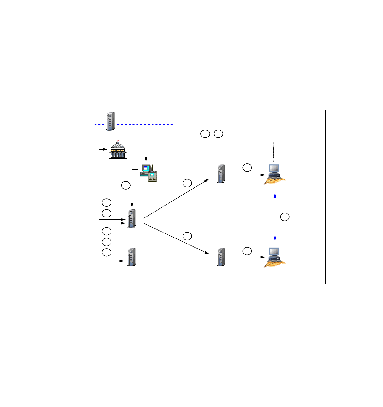
1.2.1 Session in a single-TMR environment
In order to fully understand how a Remote Control session works, it is important
to know in detail the entire data flow between the different elements of IBM Tivoli
Remote Control, starting with the most simple scenario.
Data flow for single-TMR session
Figure 1-2 shows in detail how a Remote Control session works in a single-TMR
environment without firewall restrictions.
A
TMR Server
D
PR
A
RC Tool
C
E
B
RC Server
F
G
Endpoint Mgr Endpoint GW
I
Endpoint GW
H
Figure 1-2 RC session data flow in a single-TMR environment
Based on Figure 1-2, here we provide a description of each step, from the time
the Tivoli Administrator opens the Remote Control Tool (RC Tool) until the
connection is established between the Controller and the Target.
The legend used in this diagram is explained as follows:
A The Tivoli Administrator must first open an RC Tool to be able to
select a Target from a list. As the RC Tool is located in a Policy
Region, it needs to be opened as well.
I
Controller
J
H
Target
14 IBM Tivoli Remote Control Across Firewalls
Page 35

B As soon as the RC Tool is opened, the Remote Control Server needs
to validate the Controller by checking:
– If the Controller is an Endpoint
– If the label of the Endpoint is the same as of the hostname of the
Controller
– If the interpreter of the Controller is supported and able to start a
Remote Control session
In order to get this information, the Remote Control Server needs to
contact the Endpoint Manager.
C If the Controller is validated, the Remote Control Server loads a
subset of the Remote Control policies from the Policy Region where
the RC Tool is located. For our examples, we will call these
policies. These
opened. No more are loaded for the time the Tool is active.
D At this point, the Tivoli Administrator can start a Remote Control
session by clicking the Run button of the RC Tool after selecting a
Ta r ge t .
E The Remote Control Server needs to load the rest of the Remote
Control policies. These policies are more network related and, for
example, specifies if a Remote Control Proxy or a Remote Control
Gateway should be used and which port are defined to start the
session. Unlike the basis policies, these Remote Control policies are
loaded every time a new session is started from this RC Tool.
Example 1-1 shows which policies are read when the session starts,
and which are read when the RC Tool is opened.
basis policies are only accessed when the RC Tool is
basis
F As soon as all Remote Control policies are loaded, the Remote
Control Server needs to obtain additional information for both the
Controller and the Target, such as their IP addresses. In order to get
this information, the Remote Control Server must contact the
Endpoint Manager.
G Before initiating the connection, the Remote Control Server needs to
know if the Target needs to be reached using an Endpoint
Proxy/Gateway proxy infrastructure or not. If the Target is a proxied
Endpoint, the Remote Control Server should send the request
through an Endpoint Proxy instead of using the standard Tivoli
Endpoint Gateway communication process.
H As soon as the Remote Control Server knows how it should contact
the Target, it sends the nd_start_target method down to the Target
and waits for the process to start. The local process started on the
Target machine is named EQNRCMAI.EXE.
Chapter 1. Remote Control sessions overview 15
Page 36

I As soon as the Target is started, the Remote Control Server sends
the nd_start_controller method to the Controller and waits for the
process to start. The local process started on the Controller machine
is named EQNRSMAI.EXE.
J The Remote Control session is now established. It is important to
notice that once the session established, the Controller talks directly
with the Target; this is a peer-to-peer communication. The Target is
listening on port 2501 (port 2502 for File Transfer and port 2503 for
chat) by default. On the Controller side, by default, the port is
assigned by the communication stack. However, these ports could
be easily changed by configuring the rc_def_ports Remote Control
Policy.
Tracing for single-TMR session
Example 1-1 is a subset of the output from a IBM Tivoli Management Framework
odstat command. It shows each method used to start a Remote Control session
in a single-TMR environment as described above. This trace was captured from
the time when a Tivoli Administrator opened an RC Tool until the session was
established after the Administrator clicked the Run button of this RC Tool. This
trace helps to fully depict the data flow shown in Figure 1-2 on page 14.
From the trace file, we can see what basis Remote Control policies are loaded
when the Tivoli Administrator opens the RC Tool, and all the network related
Remote Control policies that are loaded each time a Target request is started
from a Controller. We can also see that the session is first started on the Target
and then on the Controller before the peer-to-peer connection is established.
Example 1-1 RC session trace in a single-TMR environment
*******************************************************************************
Remote Control Tool is opened and RC Controller is checked.
*******************************************************************************
0.0.0 get_name_registry
1562174364.1.26 lookup
1562174364.1.1418#PcController::controller# _get_info
1562174364.1.26 lookup
1562174364.1.26 lookup
1562174364.1.4 lookup_id
1562174364.1.4##6@LCFData::ep_tnr_info_s describe
1562174364.1.26 lookup
1562174364.1.531#TMF_LCF::EpMgr# get_endpoint_key_value
1562174364.1.1413#PcRC::RemoteControl# get_policy_region
1562174364.1.1413#PcRC::RemoteControl# get_policy_region_name
1562174364.1.1413#PcRC::RemoteControl# _get_label
16 IBM Tivoli Remote Control Across Firewalls
Page 37

*******************************************************************************
“Basis” Remote Control Policies are loaded.
*******************************************************************************
1562174364.1.1127#TMF_PolicyRegion::GUI# rc_def_define
1562174364.1.1127#TMF_PolicyRegion::GUI# rc_def_uncheckedlist
0.0.0 get_name_registry
1562174364.1.26 lookup
1562174364.1.14#TMF_SysAdmin::Library# find_members
1562174364.1.184#TMF_SysAdmin::InstanceManager# find_members
1562174364.1.26 lookup
1562174364.1.4 lookup_id
1562174364.1.4##2@TMF_PolicyRegion::GUI describe
1562174364.1.4##2@TMF_PolicyRegion::GUI _get_type
1562174364.1.1139#TMF_PolicyRegion::GUI# find_members
0.0.0 get_name_registry
1562174364.1.26 lookup
1562174364.1.14#TMF_SysAdmin::Library# find_members
1562174364.1.184#TMF_SysAdmin::InstanceManager# find_members
1562174364.1.26 lookup
1562174364.1.4 lookup_id
1562174364.1.4##2@TMF_PolicyRegion::GUI describe
1562174364.1.4##2@TMF_PolicyRegion::GUI _get_type
1562174364.1.1141#TMF_PolicyRegion::GUI# find_members
1562174364.1.1413#PcRC::RemoteControl# _get_pres_object
1562174364.1.635#TMF_UI::Presentation# _get_dialogs
1562174364.1.635#TMF_UI::Presentation# _get_bitmaps
1562174364.1.1127#TMF_PolicyRegion::GUI# rc_def_command
1562174364.1.1127#TMF_PolicyRegion::GUI# rc_def_gw
1562174364.1.178#TMF_Administrator::Configuration_GUI# _get_label
1562174364.1.1127#TMF_PolicyRegion::GUI# rc_def_rcmode
1562174364.1.1127#TMF_PolicyRegion::GUI# rc_def_ftmode
1562174364.1.1127#TMF_PolicyRegion::GUI# rc_def_grace_time
1562174364.1.1127#TMF_PolicyRegion::GUI# rc_def_timeout_op
1562174364.1.1127#TMF_PolicyRegion::GUI# rc_def_optimize
1562174364.1.1127#TMF_PolicyRegion::GUI# rc_def_initstate
1562174364.1.1127#TMF_PolicyRegion::GUI# rc_def_alt_t
1562174364.1.1127#TMF_PolicyRegion::GUI# rc_def_backgrnd
1562174364.1.1127#TMF_PolicyRegion::GUI# rc_def_rate
1562174364.1.1127#TMF_PolicyRegion::GUI# rc_def_color
1562174364.1.1127#TMF_PolicyRegion::GUI# rc_def_inactivity
1562174364.1.1127#TMF_PolicyRegion::GUI# rc_def_gw
1562174364.1.1127#TMF_PolicyRegion::GUI# rc_def_comp
*******************************************************************************
Remote Control session is initiated by pressing the Run button of the RC Tool
*******************************************************************************
Chapter 1. Remote Control sessions overview 17
Page 38

1562174364.1.1413#PcRC::RemoteControl# remote_control
1562174364.1.1127#TMF_PolicyRegion::GUI# rc_def_gw
1562174364.1.1127#TMF_PolicyRegion::GUI# rc_def_ports
1562174364.1.1127#TMF_PolicyRegion::GUI# rc_def_encryption
1562174364.1.1127#TMF_PolicyRegion::GUI# rc_def_proxy
1562174364.1.26 lookup
1562174364.1.531#TMF_LCF::EpMgr# get_endpoint_key_value
1562174364.21.517+#TMF_Endpoint::Endpoint# _get_label
1562174364.17.517+#TMF_Endpoint::Endpoint# _get_label
1562174364.1.26 lookup
1562174364.1.531#TMF_LCF::EpMgr# get_endpoint_key_value
1562174364.1.531#TMF_LCF::EpMgr# get_endpoint_key_value
1562174364.21.517+#TMF_Endpoint::Endpoint# is_proxied_ep
1562174364.21.517+#TMF_Endpoint::Endpoint# nd_start_target
1562174364.1.26 lookup
1562174364.1.531#TMF_LCF::EpMgr# get_endpoint_key_value
1562174364.17.517+#TMF_Endpoint::Endpoint# nd_start_controller
1562174364.1.26 lookup
1562174364.1.531#TMF_LCF::EpMgr# get_endpoint_key_value
In order to further explain the Remote Control session process, it is necessary to
understand how the Remote Control Server knows which Controller the session
is initiated from, and which Target the session should be started to. This
information can be found in the IBM Tivoli Management Framework wtrace
command output (wtrace -jHk $DBDIR). This trace was captured at the same
time as the odstat command trace. The following examples show the detailed
information from the wtrace output about the most important lines of the IBM
Tivoli Management Framework odstat trace file shown in Example 1-1 on
page 16.
As a reference, the following information is important to understand the content
of the examples:
The object ID of the Target is 1562174364.21.517+#TMF_Endpoint::Endpoint#
The object ID of the Controller is
1562174364.17.517+#TMF_Endpoint::Endpoint#
The Object ID of the Remote Control Tool
1562174364.1.1413#PcRC::RemoteControl#
The Tivoli Administrator who initiates this session is
Root_ITSO-region(ITSO\Administrator@ITSO)
Example 1-2 details the remote_control method which could also be named the
Target request. It refers to the following line in Example 1-1 on page 16:
1562174364.1.1413#PcRC::RemoteControl# remote_control
18 IBM Tivoli Remote Control Across Firewalls
Page 39

Example 1-2 The remote_control method from a single-TMR environment
loc-ic 687 M-hdoq 1-426 776
Time run: [Mon 27-Jan 17:11:33]
Object ID: 1562174364.1.1413#PcRC::RemoteControl#
Method: remote_control
Principal: ITSO\Administrator@ITSO (8731208/0)
Path: /w32-ix86/TME/PCREMOTE/pcremote
Trans Id:
{
1562174364:1,1562174364:1,220:135
}
#4
Input Data: (encoded):
{
251658240
[
"WD_DIALOG_OWNER=1562174364.1.1413#PcRC::RemoteControl#"
"WD_GADGET_PATH=" "WD_SOURCE_PATH=btn_run" "WD_DIALOG_NAME
=pcremote" "WD_DIALOG_INSTANCE=3668:0" "WD_DESKTOP_OID=1562
174364.1.549#TMF_UI::Extd_Desktop#" "WD_DESKTOP_PID=3436"
"WD_DESKTOP_HOST=ITSO" "WD_DESKTOP_FQ_HOST=ITSO" "WD_DISPLAY
=ITSO:0" "WD_OCO_OID=1562174364.1.178#TMF_Administrator:
:Configuration_GUI#" "WD_VERSION=1" "WD_TYPE=Windows"
"LANG=en" "LC_ALL=EN_US"
]
}
"1562174364.21.517+#TMF_Endpoint::Endpoint#" "1562174364.17.517
+#TMF_Endpoint::Endpoint#" 67109120 "controla" " /R50 /B /C8"
"" "Root_ITSO-region(ITSO\Administrator@ITSO)
Example 1-3 details the is_proxied_ep method. It refers to the following line in
Example 1-1 on page 16:
1562174364.21.517+#TMF_Endpoint::Endpoint# is_proxied_ep
This method checks if the Target is behind an Endpoint Proxy/Gateway Proxy
architecture. If the result is true, Remote Control knows that an Endpoint Proxy
must be used to contact the Target. We can see that the result of this method is
false; this means that the Target is not an Endpoint connected to a Gateway
Proxy.
Chapter 1. Remote Control sessions overview 19
Page 40

Example 1-3 The is_proxied_ep method from a single-TMR environment
loc-oc 699 9
Results: (encoded):
false
Example 1-4 details the nd_start_target method. It refers to the following line in
Example 1-1 on page 16:
1562174364.21.517+#TMF_Endpoint::Endpoint# nd_start_target
This method is used to start the local Remote Control process on the Target. The
wtrace command output doesn’t show much information about this method in
this type of architecture. However, it is important to know which method is used
to start the session on the Target because, in some different situations, more
information will be available for this method.
The return code of this method is 0; this means that the session starts without an
error.
Example 1-4 The nd_start_target method from a single-TMR environment
loc-oc 700 23
Results: (encoded):
"" 0
Example 1-4 detailed the nd_start_controller method. The odstat line is:
1562174364.17.517+#TMF_Endpoint::Endpoint# nd_start_controller
This method is used to start the local Remote Control process on the Controller.
The wtrace process doesn’t show much information about this method in this
type of architecture. However, it is important to know which method is used to
start the session on the Controller because, in some different situations, more
information will be available for this method.
The return code of this method is 0; this means that the session starts without
error.
Example 1-5 The nd_start_controller method from a single-TMR environment
loc-oc 703 12
Results: (encoded):
0
20 IBM Tivoli Remote Control Across Firewalls
Page 41

1.2.2 Session in a multi-TMR environment
In order to continue to master the Remote Control session processes, it is also
important to know in detail the whole data flow between the different elements of
IBM Tivoli Remote Control in a multi-TMR environment. In a HUB-Spoke
architecture, all managed resources should be placed in the Spoke TMR, and all
profiles dedicated for the management should be created in the HUB TMR. As
RC Tools are managed resources, we assume that they are created in the Spoke
TMR. We also assume that the Targets are all managed by the Spoke TMR.
However, in order to let the Tivoli Administrator manage the Spoke TMR’s
resources from the HUB TMR, the Controller has to be declared in the HUB
TMR. This is because the resources of one Spoke TMR should never be able to
directly access resources of another Spoke TMR; only the HUB TMR resources
could manage all others. Furthermore, some resources, such as Endpoints,
Policy Region, and RemoteControl, need to be exchanged between the HUB and
Spoke TMRs. For more information about resources exchange between TMRs,
refer to the
GC32-0803.
Data flow for a multi-TMR session
Figure 1-3 shows in detail how a Remote Control session is working in a
HUB-Spoke TMR environment without firewall restrictions.
Tivoli Management Framework Planning for Deployment Guide
,
Chapter 1. Remote Control sessions overview 21
Page 42

HUB TMR Server
A
E
K
HUB RCL
Collection
Endpoint GW
Spoke RC
Tool
HUB RC
Server
HUB Endpoint Mgr
H
C
K
K
Spoke TMR Server
Spoke
PR
A
Spoke RC
Tool
D
F
B
Spoke RC
Server
G
I
Spoke Endpoint Mgr Spoke
Figure 1-3 RC session data flow in a multi-TMR environment
K
HUB
Controller
L
J
J
Target
Endpoint GW
Based on Figure 1-3, here we detail each step from the time when the Tivoli
Administrator opens an RC Tool from a Collection located in the HUB TMR until
the connection is established between the Controller and the Target.
The legend used in Figure 1-3 is explained as follows:
A The Tivoli Administrator must first open an RC Tool to be able to
select a Target from a list. As the RC Tool is located in a Policy
Region of the Spoke TMR, a Collection containing the Spoke RC
Tool is available in the HUB TMR.
B As soon as the RC Tool on the Spoke is opened, the Spoke Remote
Control Server needs to validate the Controller by checking:
– If the Controller is an Endpoint.
22 IBM Tivoli Remote Control Across Firewalls
Page 43

– If the label of the Endpoint is the same as of the hostname of the
Controller
– If the interpreter of the Controller is supported and able to start a
Remote Control session.
In order to get this information, the Spoke Remote Control Server
needs to contact the Spoke Endpoint Manager.
C As the Controller is not an Endpoint of the Spoke TMR, thus not
known by the Spoke Endpoint Manager, the Spoke Endpoint
Manager must get the Region ID from the Controller Object ID and
must find a way to contact the Endpoint Manager of this other TMR
known by the Region ID. As soon as the Spoke Endpoint Manager
find the way to contact the HUB Endpoint Manager, it transfers the
request it receives from the Spoke Remote Control Server and waits
for the return.
D If the Controller, based on the information received from the HUB
Endpoint Manager, is authorized to be a Controller, the Spoke
Remote Control server loads a subset of the Remote Control
policies. For our examples, we will call these policies
These policies are not loaded not from the Spoke RC Tool but from
the Spoke Policy Region where the Tool is located. These
policies are only accessed when the RC Tool is opened and no more
loaded for the time the Tool is active.
basis policies.
basis
E At this point, the Tivoli Administrator could decide to start a session
by clicking the Run button of the Spoke Remote Control Tool after
selecting a Target.
F The Spoke Remote Control Server needs to load the rest of the
Remote Control policies. These policies are more network related
and, for example, specify if a Remote Control Proxy or a Remote
Control Gateway should be used and which ports are defined to start
the session. Unlike the basis policies, these Remote Control policies
are loaded every time a new session is started from this Spoke RC
Tool. Example 1-7 on page 25 shows which policies are read when
the session starts and which are read when the RC Tool is opened.
G As soon as all Remote Control policies are loaded, the Spoke
Remote Control Server needs to obtain additional information for
both the Controller and the Target, such as their IP addresses. In
order to get this information, the Remote Control Server must contact
the Spoke Endpoint Manager.
Chapter 1. Remote Control sessions overview 23
Page 44

H The Spoke Endpoint Manager is able to provide information for the
Target machine as this Endpoint is part of the same TMR. However,
for the Controller, once again, it could not find any information for it
inside its Endpoint Database. The Spoke Endpoint Manager needs to
extract the Region ID of the Controller Object ID and must find a way
to contact the HUB Endpoint Manager. As soon the Spoke Endpoint
Manager find the way to contact the HUB Endpoint Manager, it
transfers the request it receives from the Spoke Remote Control
Server and waits for the return.
I Before initiating the connection, the Spoke Remote Control Server
needs to know if the Target needs to be reached using an Endpoint
Proxy/Gateway proxy infrastructure or not. If the Target is a proxied
Endpoint, the Spoke Remote Control Server should send the request
through an Endpoint Proxy instead of using the standard Tivoli
Endpoint Gateway communication process.
J As soon as the Spoke Remote Control Server knows how to contact
the Target, it sends the nd_start_target method down to the Target
and waits for the process to starts. The local process started on the
machine is named EQNRCMAI.EXE.
K As soon as the Target is started, the Spoke Remote Control Server
sends an nd_start_controller method to the Controller, but as it
knows that the Controller is not part of the Spoke TMR, it forwards
the request to the HUB TMR. The HUB Remote Control Server is
sending the nd_start_controller method to the Controller and waits
for the process to start. The local process started on the machine is
named EQNRSMAI.EXE.
L The Remote Control session is now established. Notice that once the
session established, the Controller talks directly with the Target; this
is a peer-to-peer communication. The Target is listening on port 2501
(port 2502 for File Transfer and port 2503 for chat) by default. On the
Controller side, by default, the port is assigned by the communication
stack. However, these ports could be easily changed by configuring
the rc_def_ports Remote Control Policy.
Tracing for a multi-TMR session
Example 1-6 and Example 1-7 show subsets of IBM Tivoli Management
Framework odstat command output from the HUB TMR and the Spoke TMR
respectively. They show each method used to start a Remote Control session in
a multi-TMR environment described above. This trace was captured from the
time the Tivoli Administrator opened an RC Tool until the session was
established after the Administrator clicked the Run button of this RC Tool. This
trace helps to fully depict the data flow that was shown in Figure 1-3 on page 22.
24 IBM Tivoli Remote Control Across Firewalls
Page 45

From Example 1-7, we could analyze that all methods needed to get information
from the HUB TMR are initiated on the Spoke TMR. Furthermore, all of these
methods will be found again in the HUB TMR trace file. Even if these methods
are initiated by the Spoke TMR, they are nevertheless managed by the HUB
TMR. In the Spoke TMR trace file (Example 1-7), we could also see that all
basis
Remote Control policies are loaded when the Tivoli Administrator opens the RC
Tool, and that all network related Remote Control policies are loaded each time a
Target request is started from a Controller. In addition to that, we could also
remark that the session is first started on the Target and then on the Controller
before the peer-to-peer connection between them is established.
In order to understand the information shown in the trace files, the Region IDs of
the HUB and Spoke TMRs in our environment are:
HUB TMR:
1380596993
Spoke TMR: 1519322503
Example 1-6 is the trace file from the HUB TMR Server.
Example 1-6 RC session trace from the HUB TMR in a multi-TMR environment
1380596993.1.536#TMF_LCF::EpMgr# get_endpoint_key_value
1380596993.1.536#TMF_LCF::EpMgr# get_endpoint_key_value
1380596993.1.179#TMF_Administrator::Configuration_GUI# _get_label
1380596993.1.631#TMF_UI::Extd_Desktop# connect
1380596993.7.522+#TMF_Endpoint::Endpoint# _get_label
1380596993.1.536#TMF_LCF::EpMgr# get_endpoint_key_value
1380596993.7.522+#TMF_Endpoint::Endpoint# nd_start_controller
1380596993.1.536#TMF_LCF::EpMgr# get_endpoint_key_value
Example 1-7 is the trace file from the Spoke TMR Server.
Example 1-7 RC session trace from the Spoke TMR in a multi-TMR environment
*******************************************************************************
Remote Control Tool is opened and RC Controller is checked.
*******************************************************************************
0.0.0 get_name_registry
1519322503.1.26 lookup
1519322503.1.26 lookup
1519322503.1.26 lookup
1519322503.1.26 lookup
1519322503.1.26 lookup
1519322503.1.4 lookup_id
1519322503.1.4##6@LCFData::ep_tnr_info_s describe
1519322503.1.26 lookup
1519322503.1.536#TMF_LCF::EpMgr# get_endpoint_key_value
Chapter 1. Remote Control sessions overview 25
Page 46

1380596993.1.536#TMF_LCF::EpMgr# get_endpoint_key_value
1519322503.1.26 lookup
1519322503.1.536#TMF_LCF::EpMgr# get_endpoint_key_value
1380596993.1.536#TMF_LCF::EpMgr# get_endpoint_key_value
1519322503.1.707#PcRC::RemoteControl# get_policy_region
1519322503.1.707#PcRC::RemoteControl# get_policy_region_name
1519322503.1.707#PcRC::RemoteControl# _get_label
*******************************************************************************
“Basis” Remote Control Policies are loaded.
*******************************************************************************
1519322503.1.705#TMF_PolicyRegion::GUI# rc_def_define
1519322503.1.705#TMF_PolicyRegion::GUI# rc_def_uncheckedlist
0.0.0 get_name_registry
1519322503.1.26 lookup
1519322503.1.14#TMF_SysAdmin::Library# lookup_object
1519322503.1.521#TMF_SysAdmin::InstanceManager# get_instances_interface
1519322503.1.14#TMF_SysAdmin::Library# select_instance_managers
1519322503.1.26 get_all
1519322503.1.26 lookup
1519322503.1.4 lookup_id
1519322503.1.4##6@LCFData::ep_tnr_info_s describe
1519322503.1.707#PcRC::RemoteControl# _get_pres_object
1519322503.1.679#TMF_UI::Presentation# _get_dialogs
1519322503.1.679#TMF_UI::Presentation# _get_bitmaps
1519322503.1.705#TMF_PolicyRegion::GUI# rc_def_command
1519322503.1.705#TMF_PolicyRegion::GUI# rc_def_gw
1380596993.1.179#TMF_Administrator::Configuration_GUI# _get_label
1519322503.1.705#TMF_PolicyRegion::GUI# rc_def_rcmode
1519322503.1.705#TMF_PolicyRegion::GUI# rc_def_ftmode
1519322503.1.705#TMF_PolicyRegion::GUI# rc_def_grace_time
1519322503.1.705#TMF_PolicyRegion::GUI# rc_def_timeout_op
1519322503.1.705#TMF_PolicyRegion::GUI# rc_def_optimize
1519322503.1.705#TMF_PolicyRegion::GUI# rc_def_initstate
1519322503.1.705#TMF_PolicyRegion::GUI# rc_def_alt_t
1519322503.1.705#TMF_PolicyRegion::GUI# rc_def_backgrnd
1519322503.1.705#TMF_PolicyRegion::GUI# rc_def_rate
1519322503.1.705#TMF_PolicyRegion::GUI# rc_def_color
1519322503.1.705#TMF_PolicyRegion::GUI# rc_def_inactivity
1519322503.1.705#TMF_PolicyRegion::GUI# rc_def_gw
1519322503.1.705#TMF_PolicyRegion::GUI# rc_def_comp
1380596993.1.631#TMF_UI::Extd_Desktop# connect
1519322503.1.26 lookup
*******************************************************************************
Remote Control session is initiated by pressing the Run button of the RC Tool
*******************************************************************************
26 IBM Tivoli Remote Control Across Firewalls
Page 47

1519322503.1.707#PcRC::RemoteControl# remote_control
1519322503.1.705#TMF_PolicyRegion::GUI# rc_def_gw
1519322503.1.705#TMF_PolicyRegion::GUI# rc_def_ports
1519322503.1.705#TMF_PolicyRegion::GUI# rc_def_encryption
1519322503.1.705#TMF_PolicyRegion::GUI# rc_def_proxy
1519322503.1.26 lookup
1519322503.1.536#TMF_LCF::EpMgr# get_endpoint_key_value
1519322503.18.522+#TMF_Endpoint::Endpoint# _get_label
1380596993.7.522+#TMF_Endpoint::Endpoint# _get_label
1519322503.1.26 lookup
1519322503.1.536#TMF_LCF::EpMgr# get_endpoint_key_value
1519322503.1.536#TMF_LCF::EpMgr# get_endpoint_key_value
1519322503.18.522+#TMF_Endpoint::Endpoint# is_proxied_ep
1519322503.18.522+#TMF_Endpoint::Endpoint# nd_start_target
1519322503.1.26 lookup
1519322503.1.536#TMF_LCF::EpMgr# get_endpoint_key_value
1380596993.1.536#TMF_LCF::EpMgr# get_endpoint_key_value
1380596993.7.522+#TMF_Endpoint::Endpoint# nd_start_controller
1519322503.1.26 lookup
1519322503.1.536#TMF_LCF::EpMgr# get_endpoint_key_value
1380596993.1.536#TMF_LCF::EpMgr# get_endpoint_key_value
1519322503.1.26 lookup
1519322503.1.88#TMF_SysAdmin::InstanceManager# connect
In order to explain how the Spoke Remote Control Server knows which
Controller the session is initiated from and which Target the session should be
started to, we need to analyze the output of the wtrace command from the Spoke
TMR Server. This trace was captured at the same time as the odstat command
trace.
The following examples will show the detailed information from the wtrace
command output about the most important lines of the IBM Tivoli Management
Framework odstat trace file shown in Example 1-6 on page 25 and in
Example 1-7 on page 25.
As a reference, the following information is important to understand the content
of the examples:
The Object ID of the Target is
1519322503.18.522+#TMF_Endpoint::Endpoint#
The Object ID of the Controller is
1380596993.7.522+#TMF_Endpoint::Endpoint#
The Object ID of the RC Tool is 1519322503.1.707#PcRC::RemoteControl#
The Tivoli Administrator who initiates the section is
root@lpar07.itsc.austin.ibm.com
Chapter 1. Remote Control sessions overview 27
Page 48

Example 1-8 details the remote_control method started from the Spoke TMR
Server which could also be named the Target request. It refers to the following
line in Example 1-7 on page 25:
1519322503.1.707#PcRC::RemoteControl# remote_control
Example 1-8 The remote_control method from a Spoke TMR
loc-ic 4778 M-hdoq 1-4728 782
Time run: [Tue 28-Jan 17:47:15]
Object ID: 1519322503.1.707#PcRC::RemoteControl#
Method: remote_control
Principal: root@lpar07.itsc.austin.ibm.com (-2/-2)
Path: /aix4-r1/TME/PCREMOTE/pcremote
Trans Id:
{
1519322503:1,1519322503:1,7:1207
}
#4
Input Data: (encoded):
{
14
[
"WD_DIALOG_OWNER=1519322503.1.707#PcRC::RemoteControl#"
"WD_GADGET_PATH=" "WD_SOURCE_PATH=btn_run" "WD_DIALOG_NAME
=pcremote" "WD_DIALOG_INSTANCE=30278:0" "WD_DESKTOP_OID=138
0596993.1.631#TMF_UI::Extd_Desktop#" "WD_DESKTOP_PID=1360"
"WD_DESKTOP_HOST=TIC01008" "WD_DESKTOP_FQ_HOST=TIC01008"
"WD_DISPLAY=TIC01008:0" "WD_OCO_OID=1380596993.1.179#TMF_A
dministrator::Configuration_GUI#" "WD_VERSION=1" "WD_TYPE=Wi
ndows" "LANG=en"
]
}
"1519322503.18.522+#TMF_Endpoint::Endpoint#" "1380596993.7.522+
#TMF_Endpoint::Endpoint#" 65540 "controla" " /R50 /B /C8" ""
"Root_tic01010-region(root@lpar07.itsc.austin.ibm.com)"
Example 1-9 details the is_proxied_ep method started from the Spoke TMR
Server. It refers to the following line in Example 1-7 on page 25:
1519322503.18.522+#TMF_Endpoint::Endpoint# is_proxied_ep
This method checks if the Target is behind an Endpoint Proxy/Gateway Proxy
architecture. If the result is true, Remote Control knows that an Endpoint Proxy
must be used to contact the Target. We see that the result of this method is false;
this means that the Target is not an Endpoint connected to a Gateway Proxy.
28 IBM Tivoli Remote Control Across Firewalls
Page 49

Example 1-9 The is_proxied_ep method from a Spoke TMR
loc-oc 4695 9
Results: (encoded):
false
Example 1-10 details the nd_start_target method started from the Spoke TMR
Server. It refers to the following line in Example 1-7 on page 25:
1519322503.18.522+#TMF_Endpoint::Endpoint# nd_start_target
This method is used to start the local Remote Control process on the Target. The
return code of this method is 0; this means that the session starts without error.
Example 1-10 The nd_start_target method from a Spoke TMR
loc-oc 4791 23
Results: (encoded):
"" 0
Example 1-11 details the nd_start_controller method started from the Spoke
TMR Server. It refers to the following line in Example 1-7 on page 25:
1380596993.7.522+#TMF_Endpoint::Endpoint# nd_start_controller
This method is used to start the local Remote Control process on the Controller.
However, this method is first started from the Spoke TMR, and as the Endpoint
Manager of this TMR doesn’t know the Controller Endpoint, the method must be
transferred to the HUB TMR with all needed information.
As a reference, the Target IP address is 9.3.4.247 and the Controller IP address
is 9.3.4.244.
The return code of this method is 0; this means that the session starts without
error.
Example 1-11 The nd_start_controller method from a Spoke TMR
rem-ic 4795 M-H 1-4778 236
Time run: [Tue 28-Jan 17:47:22]
Object ID: 1380596993.7.522+#TMF_Endpoint::Endpoint#
Method: nd_start_controller
Principal: root@lpar07.itsc.austin.ibm.com (0/0)
Path:
Input Data: (encoded):
"\tivoli\pcremote\eqnrsmai.exe"
{
1
Chapter 1. Remote Control sessions overview 29
Page 50

[
"/I9.3.4.247 /
],
,((!?+;
]
/Ntic01006 /
],
,((!?+;
]
/B18 /A /T /
]
;+?!((,,
]
/HRoot_tic01010-region(root@lpar07.itsc.austin.ibm.com) /
]
;+?!((,,
]
"
]
}
65540 "9.3.4.244"
rem-oc 4795 12
Results: (encoded):
0
Example 1-12 details the nd_start_controller method started from the HUB
TMR Server. It refers to the following line in Example 1-6 on page 25:
1380596993.7.522+#TMF_Endpoint::Endpoint# nd_start_controller
As soon as the Spoke TMR asked the HUB TMR Server to start the Controller,
the same nd_start_controller method is started on the HUB TMR Server. The
return code of this method is 0; this means that the session starts without error.
Example 1-12 The nd_start_controller method from a HUB TMR
loc-oc 6483 12
Results: (encoded):
0
30 IBM Tivoli Remote Control Across Firewalls
Page 51

1.2.3 Session using a Remote Control Gateway
In the following sections we describe how Remote Control sessions are
established in a firewall environment using the Remote Control Gateway
component for both single-TMR and multi-TMR environments. As this technology
had been previously developed to allow Remote Control sessions in a firewall
environment before the Remote Control Proxy technology was announced, we
won’t go into details on this process, and no trace will be discussed.
Nevertheless, it could be interesting to have an idea of how it works to compare
and understand the two different technologies.
The Remote Control Gateway must be installed on top of a Tivoli Endpoint
Gateway. If you match the Remote Control Gateway port to your firewall
configurations, you enable all Controllers to access all the Targets that reside on
the other side of the firewall, through the same Remote Control Gateway.
Furthermore, the Remote Control Gateway can’t be used to bridge two different
LAN.
Data flow for RC Gateway/single-TMR session
Figure 1-4 shows in detail how a Remote Control session works using a Remote
Control Gateway in a single-TMR environment with firewall restrictions.
Chapter 1. Remote Control sessions overview 31
Page 52
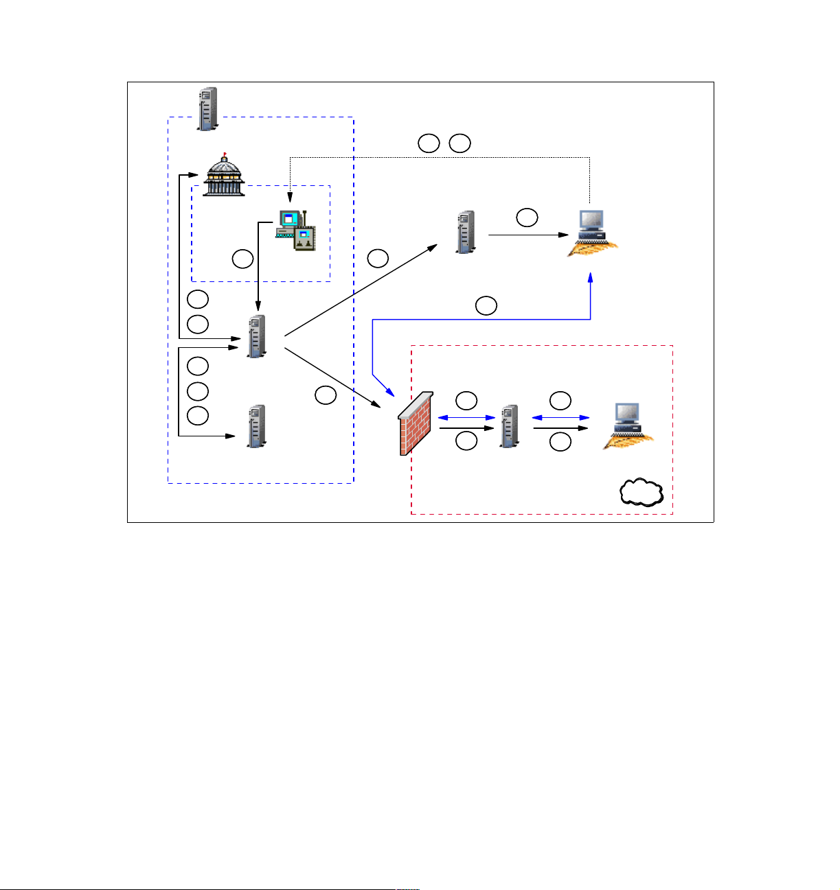
TMR Server
A
D
PR
C
E
B
F
G
Endpoint Mgr
A
RC Tool
RC Server
I
H
Firewall
Endpoint GW
J
J
H
Endpoint GW
RC Gateway
I
Figure 1-4 RC session data flow in an RC Gateway/single-TMR environment
Based on Figure 1-4, here we detail each step from the time the Tivoli
Administrator opens a Remote Control Tool until the connection is established
between the Controller and the Target.
Controller
J
H
Target
DMZ
The legend used in Figure 1-4 is explained as follows:
Steps A, B,C, D, E, F, G, H and I remain the same as for a Remote Control
session in single-TMR environment without firewall restriction. Refer to “Data
flow for single-TMR session” on page 14 for detailed information about these
steps.
The remaining step is different and is defined as follows:
J The rc_def_gw policy has been configured to force the usage of the
Remote Control Gateway, and the Remote Control Server has been
informed of that on step E. The Remote Control server then has
32 IBM Tivoli Remote Control Across Firewalls
Page 53

informed the Controller (step I) to use the Remote Control Gateway
in order to contact the Target. As the Controller knows on which
Managed Node the Remote Control Gateway is installed and which
port has to be used, it starts to communicate with the Target using
this specific network path. The Remote Control session is now
established. It is important to notice that once the session
established, the Controller talks directly with the Target, but it’s
not a
peer-to-peer communication (Controller-Target) anymore, as the
communication flow must always go through the Remote Control
Gateway. The Target is listening on the port defined in the rc_def_gw
policy. If 0 is specified as the parameter, the port is assigned by the
communication stack. On the Controller side, by default, the port is
assigned by the communication stack. However, this port could be
easily fixed by configuring the rc_def_ports Remote Control Policy.
In order to force the Remote Control session to use a Remote Control Gateway,
the rc_def_gw default policy method needs to be configured as shown in
Example 1-13.
Example 1-13 The rc_def_gw default policy method for Remote Control
#!/bin/sh
#
# Default policy method for Remote Control gateway
#
# This policy method determines whether or not to
# use the Remote Control gateway.
#
# Possible values:
# NO Do not use the Remote Control gateway.
# YES <ManagedNode-label> <GatewayPort> <MaxSessions> IP:<IP-Port>
# Use the specified Remote Control gateway,
# where:
# <ManagedNode-label> is the name of the managed node
# to be used as Remote Control gateway.
# <GatewayPort> is the TCP/IP port used by the Remote
# Control gateway to listen for connection request from
# controllers.
# <MaxSessions> is the number of Tivoli Remote Control
# sessions between a controller and target that the Remote
# Control gateway can handle on the same incoming port.
# The maximum value is 64.
# <IP-Port> is the local TCP/IP port used by the Remote
# Control gateway to communicate with TCP/IP targets.
# If it has the value 0, the Remote Control gateway uses
# a port generated by the communication stack.
#
# Default value: NO
Chapter 1. Remote Control sessions overview 33
Page 54
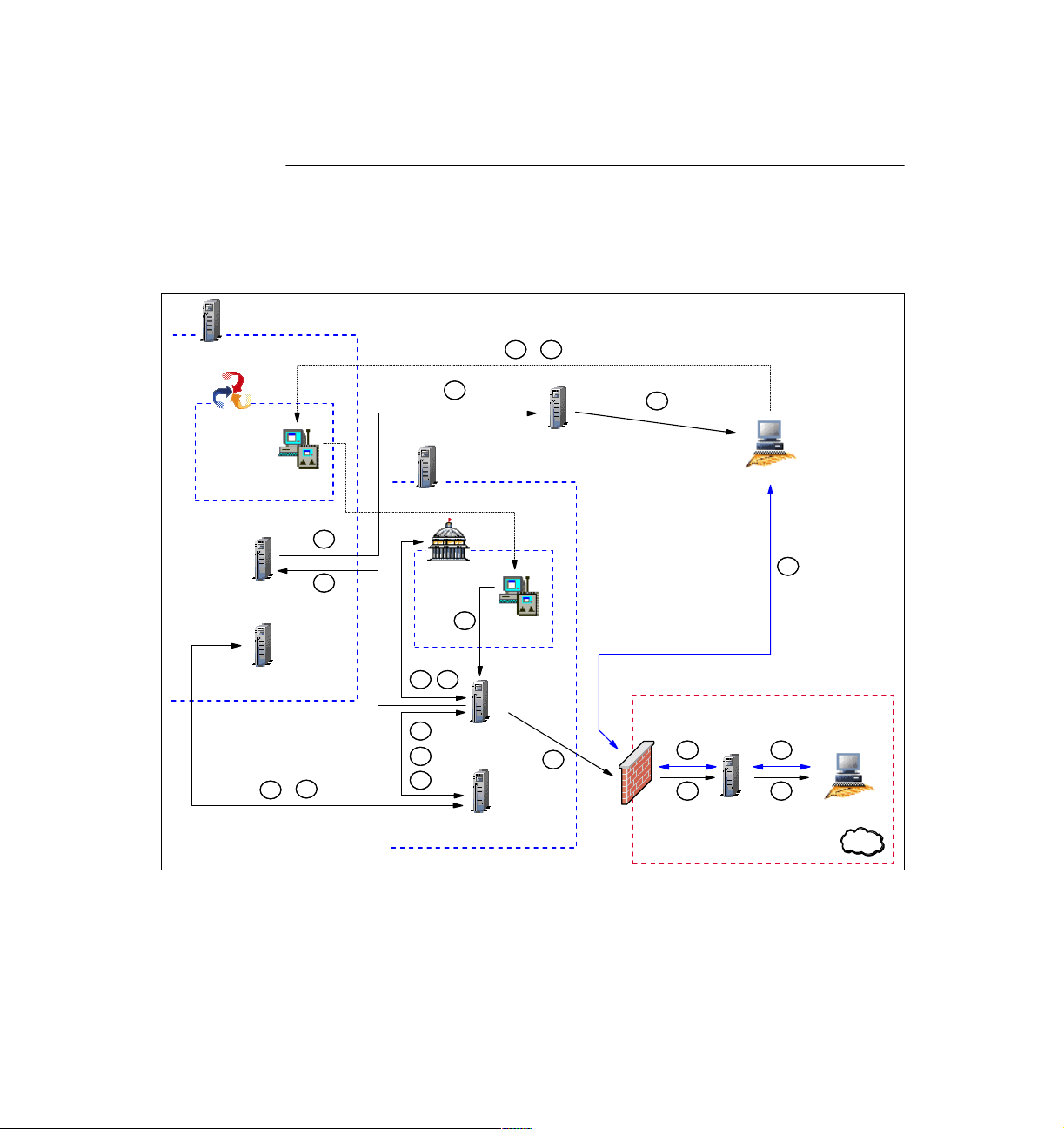
HUB TMR Server
echo "YES tic01002 8877 64 IP:0"
exit 0
Data flow for an RC Gateway/multi-TMR session
Figure 1-5 shows in detail how a Remote Control session works using a Remote
Control Gateway in a multi-TMR environment with firewall restrictions.
A
E
HUB RCL
Collection
Spoke RC
HUB RC
Server
HUB Endpoint Mgr
C
Tool
K
HUB
Endpoint GW
Spoke TMR Server
K
K
H
Spoke
PR
A
Spoke RC
Tool
D
F
B
Spoke RC
Server
G
I
Spoke Endpoint Mgr
J
K
Firewall
Figure 1-5 RC session data flow in an RC Gateway/multi-TMR environment
Controller
L L
J J
Endpoint GW
RC Gateway
L
Target
DMZ
Based on Figure 1-5, here we detail each step from the time when the Tivoli
Administrator opens a Remote Control Tool until the connection is established
between the Controller and the Target.
34 IBM Tivoli Remote Control Across Firewalls
Page 55

The legend used in Figure 1-5 is explained as follows:
Steps A, B,C, D, E, F, G, H, I, J, and K remain the same as for a Remote Control
session in a multi-TMR environment without the firewall restriction. Refer to “Data
flow for a multi-TMR session” on page 21 for detailed information about these
steps.
The remaining step is different and is defined as follows:
L The rc_def_gw policy has been configured to force the usage of the
Remote Control Gateway and the Remote Control Server has been
informed of that on step F. The Remote Control server then has
informed the Controller (step K) to use the Remote Control Gateway
in order to contact the Target. As the Controller knows on which
Managed Node the Remote Control Gateway is installed and which
port has to be used, it could start to communicate with the Target
using this specific network path. The Remote Control session is now
established. It is important to notice that once the session
established, the Controller talks directly with the Target, but it’s
peer-to-peer communication (Controller-Target) anymore, as the
communication flow must always go through the Remote Control
Gateway. The Target is listening on port defined in the rc_def_gw
policy. If 0 is specified as parameter, the port is assigned by the
communication stack. On the Controller side, by default, the port is
assigned by the communication stack. However, this port could be
easily fixed by configuring the rc_def_ports Remote Control Policy.
not a
In order to force the Remote Control session to use a Remote Control Gateway,
the rc_def_gw default policy method needs to be configured as shown in
Example 1-13 on page 33. This has to be done in the Spoke TMR where the
Remote Control Object is located.
1.2.4 Session using Remote Control Proxies Standalone
In the following sections we describe the Remote Control Proxy Standalone
architecture for both single-TMR and multi-TMR environments.
The Remote Control Proxy components enable machines on a side of a firewall
to communicate, through a common definable port, to machines on the other
side of the firewall. Thus, the Controller is able to start a session with a Target by
minimizing the impact on the security infrastructure.
However, the Remote Control Proxy Standalone solution could only be used if a
standard Tivoli Endpoint Gateway is installed in the same network zone as the
Targets. Otherwise, the Remote Control Proxy on top of the Tivoli Firewall
Security Toolbox solution needs to be deployed.
Chapter 1. Remote Control sessions overview 35
Page 56

The RC Target Proxy emulates the Target located in another network zone to the
Controller. The Target Proxy must be able to communicate with the Controller
without any firewall constraints, and thus must be located in the same network
zone as the Controller.
On the other side, the RC Controller Proxy emulates the Controller located in
another zone to the Target. The Controller Proxy must be able to communicate
with the Target without any firewall constraints, and thus must be located in the
same network zone as the Target.
Data flow for RC Proxy Standalone/single-TMR session
Figure 1-6 shows in detail how a Remote Control session works using a Remote
Control Proxy Standalone architecture in a single-TMR environment with firewall
restrictions.
TMR Server
PR
C
E
B
F
G
Endpoint Mgr
A
RC Tool
RC Server
A
D
I
Endpoint GW
RC Target Proxy
H
I
Controller
J
J
Firewall
J
H
Figure 1-6 RC session data flow in an RC Proxy Standalone/single-TMR
RC Controller Proxy
Endpoint GW
J
Target
H
DMZ
36 IBM Tivoli Remote Control Across Firewalls
Page 57

Based on Figure 1-6, here we detail each step from the time the Tivoli
Administrator opens a Remote Control Tool until the connection is established
between the Controller and the Target using the Remote Control Proxies.
The legend used in Figure 1-6 is explained as follows:
Steps A, B,C, D, E, F, G, H and I are similar to a Remote Control session in
single-TMR environment without firewall restriction. Refer to “Data flow for
single-TMR session” on page 14 for detailed information about these steps.
The remaining step is different and defined as follows:
J Both sessions on the Target and on the Controller are now started.
At this step, the Controller needs to establish the link to control the
Target. The rc_def_proxy policy has been configured to force the
usage of the Remote Control Proxies and the Remote Control Server
has been informed of that on step E. The Remote Control server then
has informed the Controller (step I) to use the RC Target Proxy in
order to contact the Target. The Controller is able now to transfer the
connection request to the RC Target Proxy as it got its IP address.
When the RC Target Proxy receives the request containing the IP
address of the requested Target, it can start searching in the
rcproxy.route file for the RC Controller Proxy the Target is
connected to. In fact, this file contains a list of all distant Endpoints
and their assigned RC Controller Proxy and needs to be manually
customized. For more information about how to configure this file,
refer to 3.3.2, “Remote Control Proxy configuration” on page 104.
The RC Target Proxy then contacts the correspondent RC Controller
Proxy to forward the Target connection request. The RC Controller
Proxy uses the Target information stored in the first request to start a
session with the Target.
The Remote Control session is now established. It is important to
notice that once the session established, the Controller talks directly
with the Target, but it’s
not a peer-to-peer communication
(Controller-Target) anymore, as the communication flow must always
go through the Remote Control Proxies.
The Target is listening on port defined in the rc_def_ports policy.
On the Controller side, by default, the port is assigned by the
communication stack. However, these ports could be easily changed
by configuring the rc_def_ports Remote Control Policies. The RC
Target Proxy and the RC Controller Proxy are listening on the port
defined during the installation process. The port specified in the
rc_def_proxy policy must be the same as defined during the
installation process of the RC Target Proxy. The configuration of
these RC Proxies ports could be reviewed by editing the rcproxy.cfg
Chapter 1. Remote Control sessions overview 37
Page 58

configuration file. However, if you decided to change this port, you
need to also review the rc_def_proxy policy. For more information
about the RC Proxies configuration files, refer to
Control User’s Guide
, SC23-4842.
IBM Tivoli Remote
Sometimes, the Controller could be in a secure zone and managed by a local
Tivoli Endpoint Gateway and the Target could be in another secure zone and
also be managed by a local Tivoli Endpoint Gateway. In this case, two firewalls
separate the Controller and its RC Target Proxy from the Target and its RC
Controller Proxy. The TFST Relay could be installed in the zone between the two
secure zones and used to pass the information between the RC Target Proxy
and the RC Controller Proxy.
In order to implement the Remote Control session to use Remote Control
Proxies, the rc_def_proxy default policy method needs to be configured as
shown in Example 1-14.
Example 1-14 The rc_def_proxy default policy method for Remote Control
#!/bin/sh
#
# Default policy method for Remote Control Proxy
#
# This policy method determines whether to use Remote Control Proxies.
# If you use Remote Control Proxies, rc_def_proxy defines how the controller
# uses the Remote Control Proxies to start a session with a target across a
# firewall.
#
# Possible values:
#
# NO Do not use the Remote Control Proxies.
#
# YES <configuration type> <rc proxy ip address> <rc proxy port>
# Use the Remote Control Proxies, where:
#
# <configuration type>
# Identifies the following scenarios:
#
# auto
# The controller and Remote Control Proxies
# search the route to the target using the
# information stored by
# Tivoli Firewall Security Toolbox.
#
# manual
# The Remote Control Proxies run as standalone.
# The controller uses the network address that
# you specify in this method to reach
38 IBM Tivoli Remote Control Across Firewalls
Page 59

# the machine where the target
# proxy runs.
#
# <rc proxy ip address>
# Identifies the machine where the target proxy
# runs. You must use this parameter only with
# the manual configuration type.
#
# <rc proxy port>
# Identifies the port that the target proxy uses to
# communicate with the controller or the controller
# proxy.
#
# Default value: NO
#
#
# Examples follow.
#
# First example:
# YES manual 192.168.100.50 3501
#
# Second example:
# YES auto 3501
#
# Third example:
# NO
#
echo "YES manual 9.3.4.169 8888"
exit 0
Data flow for an RC Proxy Standalone/multi-TMR session
Figure 1-7 shows in detail how a Remote Control session works using a Remote
Control Proxy Standalone architecture in a multi-TMR environment with firewall
restrictions.
Chapter 1. Remote Control sessions overview 39
Page 60

HUB TMR Server
A
E
HUB RCL
Collection
Spoke RC
HUB RC
Server
HUB Endpoint Mgr
C
Tool
K
HUB
Endpoint GW
Spoke TMR Server
K
K
H
Spoke
PR
A
Spoke RC
Tool
D
F
B
Spoke RC
Server
G
I
Spoke Endpoint Mgr
J
K
L
Firewal l
Figure 1-7 RC session data flow in an RC Proxy Standalone/multi-TMR
Controller
RC Target Proxy
L
RC Controller Proxy
J
Endpoint GW
L
L
Target
J
DMZ
Based on Figure 1-7, here we detail each step from the time the Tivoli
Administrator opens a Remote Control Tool until the connection is established
between the Controller and the Target using the Remote Control Proxies.
The legend used in Figure 1-7 is explained as follows:
Steps A, B,C, D, E, F, G, H, I, J and K are similar to a Remote Control session in
multi-TMR environment without firewall restriction. Refer to “Data flow for a
multi-TMR session” on page 21 for detailed information about these steps.
The remaining step is different and defined as follows:
L Both sessions on the Target and on the Controller are now started.
At this step, the Controller need to establish the link to control the
Target. The rc_def_proxy policy has been configured to force the
usage of the Remote Control Proxies and the Remote Control Server
40 IBM Tivoli Remote Control Across Firewalls
Page 61

has been informed of that on step F. The Remote Control server then
has informed the Controller (step K) to use the RC Target Proxy in
order to contact the Target. The Controller is able now to transfer the
connection request to the RC Target Proxy as it got its IP address.
When the RC Target Proxy receives the request containing the IP
address of the requested Target, it can start searching in the
rcproxy.route file for the RC Controller Proxy the Target is
connected to. In fact, this file contains a list of all distant Endpoints
and their assigned RC Controller Proxy and needs to be manually
customized. For more information about how to configure this file,
refer to 3.3.2, “Remote Control Proxy configuration” on page 104.
The RC Target Proxy then contacts the correspondent RC Controller
Proxy to forward the Target connection request. The RC Controller
Proxy uses the Target information stored in the first request to start a
session with the Target.
The Remote Control session is now established. It is important to
notice that once the session established, the Controller talks directly
with the Target, but it’s
(Controller-Target) anymore, as the communication flow must always
go through the Remote Control Proxies.
The Target is listening on port defined in the rc_def_ports policy.
On the Controller side, by default, the port is assigned by the
communication stack. However, these ports could be easily changed
by configuring the rc_def_ports Remote Control Policies. The RC
Target Proxy and the RC Controller Proxy are listening on the port
defined during the installation process. The port specified in the
rc_def_proxy policy must be the same as defined during the
installation process of the RC Target Proxy. The configuration of
these RC Proxies ports could be reviewed by editing the rcproxy.cfg
configuration file. However, if you decided to change this port, you
need to also review the rc_def_proxy policy. For more information
about the RC Proxies configuration files, refer to
Control User’s Guide
not a peer-to-peer communication
IBM Tivoli Remote
, SC23-4842
Sometimes, the Controller could be in a secure zone and managed by a local
Tivoli Endpoint Gateway and the Target could be in another secure zone and
also managed by a local Tivoli Endpoint Gateway. In this case, two firewalls
separate the Controller and RC Target Proxy from the Target and RC Controller
Proxy. The TFST Relay could be installed in the zone between the two secure
zones and used to pass the information from the RC Target Proxy to the RC
Controller Proxy
Chapter 1. Remote Control sessions overview 41
Page 62

In order to implement the Remote Control session to use Remote Control
Proxies, the rc_def_proxy default policy method needs to be configured as
shown in Example 1-14 on page 38. This has to be done in the Spoke TMR
where the Remote Control Object is located.
Tracing for RC Proxy Standalone
The Tivoli methods used to start a session in a Remote Control Proxy
Standalone architecture are the same used to start a session in a non-secure
environment. Refer to Example 1-1 on page 16 for a subset of an IBM Tivoli
Management Framework odstat output trace file for a single-TMR architecture
and to the Example 1-6 on page 25 and Example 1-7 on page 25 for multi-TMR
architecture.
Sections “Tracing for single-TMR session” on page 16 and “Tracing for a
multi-TMR session” on page 24 provided the details of the most important
methods used to start a Remote Control session both in a single-TMR and
multi-TMR architecture. As mentioned, the methods are almost the same to start
a Remote Control session in a secure environment. Thus, we only provide in this
section the main differences for the most important methods.
The Target request, managed by the remote_control method, remains the same
in a secure environment. For more information about this method, refer to
Example 1-2 on page 19 for a single-TMR architecture and to Example 1-8 on
page 28 for a multi-TMR architecture.
Example 1-15 details the is_proxied_ep method started from either the TMR
Server in a single-TMR architecture or from the Spoke TMR Server in a
multi-TMR architecture. It refers to the following line in Example 1-7 on page 25:
1519322503.29.522+#TMF_Endpoint::Endpoint# is_proxied_ep
This method checks if the Target is behind an Endpoint Proxy/Gateway Proxy
architecture. If the result is true, Remote Control knows that an Endpoint Proxy
must be used to contact the Target. We see that the result of this method is
false; this means that the Target is not an Endpoint connected to a Gateway
Proxy.
As a reference, the following information is important to understand the content
of the examples:
The Target IP address is 10.10.10.7
The RC Target Proxy IP address is 9.3.4.169 and it is defined in the
rc_def_proxy policy file
The Controller IP address is 9.3.4.244
42 IBM Tivoli Remote Control Across Firewalls
Page 63

Example 1-15 The is_proxied_ep method for an RC Proxy Standalone architecture
rem-ic 695 M-H 1-683 21
Time run: [Thu 30-Jan 11:42:46]
Object ID: 1519322503.29.522+#TMF_Endpoint::Endpoint#
Method: is_proxied_ep
Principal: root@tic01002 (0/0)
Path:
Input Data: (encoded):
"10.10.10.7"
rem-oc 695 9
Results: (encoded):
false
Example 1-16 details the nd_start_target method started from either the TMR
Server in a single-TMR architecture or from the Spoke TMR Server in a
multi-TMR architecture. It refers to the following line in Example 1-7 on page 25:
1519322503.18.522+#TMF_Endpoint::Endpoint# nd_start_target
This method is used to start the local Remote Control process on the Target. The
return code of this method is 0; this means that the session starts without error.
Example 1-16 The nd_start_target method for an RC Proxy Standalone architecture
rem-ic 1517 M-H 1-1504 199
Time run: [Thu 30-Jan 13:10:39]
Object ID: 1519322503.29.522+#TMF_Endpoint::Endpoint#
Method: nd_start_target
Principal: root@tic01002 (0/0)
Path:
Input Data: (encoded):
"\tivoli\pcremote\eqnrcmai.exe"
{
3
[
"10.10.10.7" "/HRoot_tic01002-region(root@tic01002)"
" /R50 /B /C8 /V1519322503.1.702#PcRC::RemoteControl# /I"
]
}
65540
rem-oc 1517 23
Results: (encoded):
Chapter 1. Remote Control sessions overview 43
Page 64

"" 0
Example 1-17 details the nd_start_controller method started from the Spoke
TMR Server in a multi-TMR architecture because it shows more useful
information to understand how the information about the Target Proxy is passed
to the Controller. It refers to the following line in Example 1-7 on page 25:
1380596993.7.522+#TMF_Endpoint::Endpoint# nd_start_controller
This method is used to start the local Remote Control process on the Controller.
The 8888 number, in fact, is the port number on which the Target Proxy is
listening. This port is configurable and defined in the rc_def_proxy Policy. The
return code of this method is 0; this means that the session starts without error.
Example 1-17 The nd_start_controller method for RC Proxy Standalone architecture
rem-ic 972 M-H 1-955 256
Time run: [Thu 30-Jan 11:49:00]
Object ID: 1380596993.7.522+#TMF_Endpoint::Endpoint#
Method: nd_start_controller
Principal: root@lpar07.itsc.austin.ibm.com (0/0)
Path:
Input Data: (encoded):
"\tivoli\pcremote\eqnrsmai.exe"
{
1
[
"/I10.10.10.7 /
],
,((!?+;
]
/Ntic01007 /
],
,((!?+;
]
/C8888 /F9.3.4.169 /B29 /A /T /
]
;+?!((,,
]
/HRoot_tic01010-region(root@lpar07.itsc.austin.ibm.com) /
]
;+?!((,,
]
"
]
}
65540 "9.3.4.244"
44 IBM Tivoli Remote Control Across Firewalls
Page 65

rem-oc 972 12
Results: (encoded):
0
1.2.5 Session using Remote Control Proxies in a TFST environment
In the following sections we describe the Remote Control Proxy architecture
running on top of Tivoli Firewall Security Toolbox for both single-TMR and
multi-TMR environments.
The Remote Control Proxy components enable machines on one side of a
firewall to communicate, through a common definable port, with machines on the
other side of the firewall. The Controller is able to start a Target session by
minimizing the impact on the security infrastructure.
The Remote Control Proxy-TFST solution can only be used if a Tivoli Firewall
Security Toolbox environment is already deployed.
The Endpoint Proxy emulates the Endpoints located in another network zone to
the standard Tivoli Gateway located in the same network zone as the TMR
Server. Thus, the Endpoint Proxy is able to find the path to contact all distant
Endpoints. In this context, the RC Target Proxy, which emulates the Target
located in another network zone, could take the advantage of the Endpoint Proxy
to find the way to contact the Targets. However, the Target Proxy must be able to
communicate with the Controller without any firewall constraints, and thus must
be located in the same network zone as the Controller.
On the other side, the RC Controller Proxy emulates the Controller located in
another zone to the Target. The RC Controller Proxy must be able to
communicate with the Target without any firewall constraints, and thus must be
located in the same network zone as the Target. Furthermore, as the RC Target
Proxy is installed on top of the Endpoint Proxy, the RC Controller Proxy must be
installed on the top of the Gateway Proxy, which emulates a standard Tivoli
Gateway to the distant Endpoints.
Data flow for RC Proxy-TFST/single-TMR session
Figure 1-8 shows in detail how a Remote Control session works using a Remote
Control Proxy - TFST architecture in a single-TMR environment with firewall
restrictions:
Chapter 1. Remote Control sessions overview 45
Page 66

A
D
TMR Server
PR
C
E
B
F
G
Endpoint Mgr
A
RC Tool
RC Server
Endpoint GW
I
H
Firewall
DMZ
I
Controller
J
RC Target Proxy
J
J
H
Endpoint Proxy
H
J
RC Contr. Proxy
Firewall
J
H
Gateway Proxy
Target
H
External
J
H
Relay 2 TFST
Relay 1 TFST
J
H
Figure 1-8 RC session data flow in an RC Proxy-TFST/single-TMR environment
Based on Figure 1-8, here we detail each step from the time the Tivoli
Administrator opens a Remote Control Tool until the connection is established
between the Controller and the Target through the Remote Control Proxies.
The legend used in Figure 1-8 is explained as follows:
Steps A, B,C, D, E, F, G and I remain the same as for a Remote Control session
in single-TMR environment without firewall restriction. Refer to “Data flow for
single-TMR session” on page 14 for detailed information about these steps.
The remaining steps are different and are defined as follows:
H This step remains almost the same as for a standard session in a
non-secure environment. However, in a standard process the
nd_start_target method is sent to the Target using the standard
46 IBM Tivoli Remote Control Across Firewalls
Page 67

Endpoint Communication Protocol packets. In a TFST environment,
these packets are encapsulated by the Endpoint Proxy inside
common HTTP packets. HTTP protocol has been chosen, as it is
“firewall friendly” protocol. The packets are then rebuilt into Tivoli
proprietary communication protocol by the Gateway proxy to let the
distant Targets understand the order to start an RC session.
When the request arrives from the standard Tivoli environment, it
contains the label of the distant Endpoint, which is the Target in this
case. The Endpoint Proxy owns its proper Endpoint Database where
key information about each distant Endpoint is stored and notably its
Gateway Proxy. Using this information, the Endpoint Proxy is able to
forward the request to the correct Gateway Proxy, which will forward
it at the end to the Endpoint.
In the situation depicted in Figure 1-8 on page 46, there are two
firewalls separating the standard Tivoli environment from the distant
Endpoints. To let the Endpoint Proxy, which needs to be on the same
network zone that the Tivoli Endpoint Gateway, communicate with
the Gateway Proxy, which needs to be close to the distant Endpoints,
a second instance of the Relay is needed in the zone between the
firewalls. Its role it just to forward the packets to the final destination
between the different network zones. Multiple Relays could be
chained to cross multiple secure zones.
J Both sessions on the Target and on the Controller are now started.
At this step, the Controller need to establish the link to control the
Target. The rc_def_proxy policy has been configured to force the
usage of the Remote Control Proxies and the Remote Control Server
has been informed of that on step E. The Remote Control server then
has informed the Controller (step I) to use the RC Target Proxy in
order to contact the Target. The Controller is able now to transfer the
connection request to the RC Target Proxy.
As only the RC Target Proxy port is defined in the rc_def_proxy
policy in an auto mode, the Controller only receives the address of
the Endpoint Proxy. As the RC Target Proxy must be installed on the
same machine as the Endpoint Proxy, the Controller can forward the
Target request to the RC Target Proxy using the address of the
Endpoint Proxy.
When the Target Proxy receives the request, it needs to find which
RC Controller Proxy the Endpoint is attached to. In a Tivoli Firewall
Security Toolbox environment, the Endpoint Proxy is in charge to
manage the key information of the Endpoint. To know the right path
to contact the Target, the RC Target Proxy needs to ask the Endpoint
Proxy for this information. The Endpoint Proxy provides the host
Chapter 1. Remote Control sessions overview 47
Page 68

name of the Gateway Proxy which the Target is connected to. As the
RC Controller Proxy must be installed on the same machine as the
Gateway Proxy, the RC Target proxy is able to connect to this RC
Controller Proxy and forward the Target request using the Gateway
Proxy IP Address provided by the Endpoint Proxy. The RC Controller
Proxy then uses the Target information stored in the first request to
start a session with the Target.
The Remote Control session is now established. It is important to
notice that once the session established, the Controller talks directly
with the Target, but it’s
(Controller-Target) anymore, as the communication flow must always
go through the Remote Control Proxies.
The Target is listening on port defined in the rc_def_ports policy.
On the Controller side, by default, the port is assigned by the
communication stack. However, these ports could be easily changed
by configuring the rc_def_ports Remote Control Policies. The RC
Target Proxy and the RC Controller Proxy are listening on the port
defined during the installation process. The port specified in the
rc_def_proxy policy must be the same as defined during the
installation process of the RC Target Proxy. The configuration of
these RC Proxies ports could be reviewed by editing the rcproxy.cfg
configuration file. However, if you decided to change this port, you
need to also review the rc_def_proxy policy. For more information
about the RC Proxies configuration files, refer to
Control User’s Guide
not a peer-to-peer communication
IBM Tivoli Remote
, SC23-4842.
In the scenario depicted in Figure 1-8 on page 46, there are two
firewalls separating the standard Tivoli environment from the distant
Endpoints. To let the RC Target Proxy, which needs to be on the
same network zone that the Controller, communicate with the RC
Controller Proxy, which needs to be close to the Target, a second
instance of a Relay is needed. Its role it just to forward the packet to
the final destination between the different network zones. Multiple
Relays could be chained to cross all multiple secure zones. The
Relay is not a Remote Control Component, it is a Tivoli Firewall
Security Toolbox one. In fact, one instance of the Relay is needed to
manage network flow between the Endpoint Proxy and Gateway
Proxy and another instance of the same Relay need to be installed
on the same machine as the first Relay instance to manage the
network flow between the Remote Control Proxies.
In order to implement the Remote Control session to use Remote Control
Proxies, the rc_def_proxy default policy method needs to be configured, for
instance, as shown in Example 1-18.
48 IBM Tivoli Remote Control Across Firewalls
Page 69

Example 1-18 The rc_def_proxy default policy method for Remote Control
#!/bin/sh
#
# Default policy method for Remote Control Proxy
#
# This policy method determines whether to use Remote Control Proxies.
# If you use Remote Control Proxies, rc_def_proxy defines how the controller
# uses the Remote Control Proxies to start a session with a target across a
# firewall.
#
# Possible values:
#
# NO Do not use the Remote Control Proxies.
#
# YES <configuration type> <rc proxy ip address> <rc proxy port>
# Use the Remote Control Proxies, where:
#
# <configuration type>
# Identifies the following scenarios:
#
# auto
# The controller and Remote Control Proxies
# search the route to the target using the
# information stored by
# Tivoli Firewall Security Toolbox.
#
# manual
# The Remote Control Proxies run as standalone.
# The controller uses the network address that
# you specify in this method to reach
# the machine where the target
# proxy runs.
#
# <rc proxy ip address>
# Identifies the machine where the target proxy
# runs. You must use this parameter only with
# the manual configuration type.
#
# <rc proxy port>
# Identifies the port that the target proxy uses to
# communicate with the controller or the controller
# proxy.
#
# Default value: NO
#
#
# Examples follow.
#
Chapter 1. Remote Control sessions overview 49
Page 70

# First example:
# YES manual 192.168.100.50 3501
#
# Second example:
# YES auto 3501
#
# Third example:
# NO
#
echo "YES auto 5020"
exit 0
Data flow for RC Proxy-TFST/multi-TMR session
Figure 1-9 shows in detail how a Remote Control session works using a Remote
Control Proxy - TFST architecture in a multi-TMR environment with firewall
restrictions:
50 IBM Tivoli Remote Control Across Firewalls
Page 71
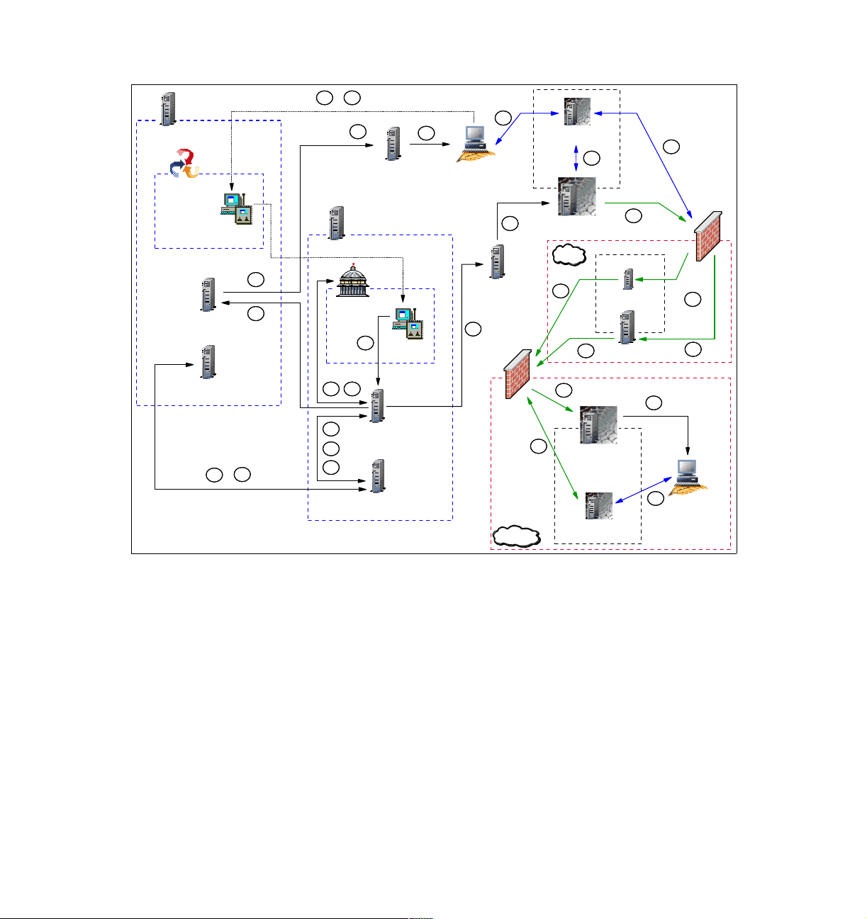
HUB TMR Server
HUB RCL
Collection
HUB RC
Server
HUB Endpoint Mgr
Spoke RC
Tool
H
C
A
E
K
Endpoint GW
Spoke TMR Server
K
K
Spoke
PR
A
D
F
B
Spoke RC
Server
G
I
Spoke Endpoint Mgr
HUB
Spoke RC
Tool
K
Controller
L
J
Spoke
Endpoint GW
J
Firewall
RC Target Proxy
L
Endpoint Proxy
DMZ
L
J
J
L
Gateway Proxy
J
Relay 2 TFST
Relay 1 TFST
L
Firewall
L
J
J
L
Target
External
RC Contr. Proxy
Figure 1-9 RC session data flow in an RC Proxy-TFST/multi-TMR environment
Based on Figure 1-9, here we detail each step from the time the Tivoli
Administrator opens a Remote Control Tool until the connection is established
between the Controller and the Target through the Remote Control Proxies.
The legend used in Figure 1-9 is explained as follows:
Steps A, B,C, D, E, F, G, H, I and K remain the same as for a Remote Control
session in a multi-TMR environment without firewall restriction. Refer to “Data
flow for a multi-TMR session” on page 21 for detailed information about these
steps.
The remaining steps are different and are defined as follows:
J This step remains almost the same as for a standard session in a
non-secure environment. However, in a standard process, the
Chapter 1. Remote Control sessions overview 51
Page 72

nd_start_target method is sent to the Target using the standard
Endpoint Communication Protocol packets. In a TFST environment,
these packets are encapsulated by the Endpoint Proxy inside
common HTTP packets. HTTP protocol has been chosen, as it is
considered a “firewall friendly” protocol. The packets are then rebuilt
into Tivoli proprietary protocol by the Gateway proxy to let the distant
Targets understand the order to start an RC session.
When the request arrives from the standard Tivoli environment, it
contains the label of the distant Endpoint, which is the Target in this
case. The Endpoint Proxy owns its proper Endpoint Database where
key information about each distant Endpoint is stored and notably its
Gateway Proxy. Using this information, the Endpoint Proxy is able to
forward the request to the right Gateway Proxy which will forward it at
the end to the Endpoint.
In the situation depicted in Figure 1-9 on page 51, there are two
firewalls separating the standard Tivoli environment from the distant
Endpoints. To let the Endpoint Proxy (which needs to be on the same
network zone as the Tivoli Endpoint Gateway) communicate with the
Gateway Proxy (which needs to be close to the distant Endpoints), a
second instance of the Relay is needed in the zone between the
firewalls. Its role is just to forward the packets to the final destination
between the different network zones. Multiple Relays could be
chained to cross multiple secure zones.
L Both sessions on the Target and on the Controller are now started.
At this step, the Controller need to establish the link to control the
Target. The rc_def_proxy policy has been configured to force the
usage of the Remote Control Proxies and the Remote Control Server
has been informed of that on step I. The Remote Control server then
has informed the Controller (step K) to use the RC Target Proxy in
order to contact the Target. The Controller is able now to transfer the
connection request to the RC Target Proxy.
As only the RC Target Proxy port is defined in the rc_def_proxy
policy in an auto mode, the Controller only receives the address of
the Endpoint Proxy. As the RC Target Proxy must be installed on the
same machine as the Endpoint Proxy, the Controller can forward the
Target request to the RC Target Proxy using the address of the
Endpoint Proxy.
When the Target Proxy receives the request, it needs to find on
which RC Controller Proxy the Endpoint is attached to. In a TFST
environment, the Endpoint Proxy is in charge to manage the key
information of the Endpoint. To know the right path to contact the
Target, the RC Target Proxy needs to ask the Endpoint Proxy for this
information. The Endpoint Proxy provides the host name of the
52 IBM Tivoli Remote Control Across Firewalls
Page 73

Gateway Proxy on which the Target is connected to. As the RC
Controller Proxy must be installed on the same machine as the
Gateway Proxy, the RC Target proxy is able to connect to this RC
Controller Proxy and forward the Target request using the Gateway
Proxy Address provided by the Endpoint Proxy. The RC Controller
Proxy uses the Target information stored in the first request to start a
session with the Target.
The Remote Control session is now established. It is important to
notice that once the session established, the Controller talks directly
with the Target, but it’s NOT a peer-to-peer communication
(Controller-Target) anymore, as the communication flow must always
go through the Remote Control Proxies.
The Target is listening on port define in the rc_def_port policy.
On the Controller side, by default, the port is assigned by the
communication stack. However, these ports could be easily changed
by configuring the rc_def_ports Remote Control Policies. The RC
Target Proxy and the RC Controller proxy are listening on the port
defined during the installation process. The port specified in the
rc_def_proxy policy must be the same as defined during the
installation process of the RC Target Proxy. The configuration of
these RC Proxies port could be reviewed by editing the rcproxy.cfg
configuration file. However, if you decided to change this port, you
need to also review the rc_def_proxy policy. For more information
about the RC Proxies configuration files, refer to
Control User’s Guide
, SC23-4842.
IBM Tivoli Remote
In the situation depicted in Figure 1-9 on page 51, there are two
firewalls separating the standard Tivoli environment from the distant
Endpoints. To let the RC Target Proxy (which needs to be on the
same network zone as the Controller) communicate with the RC
Controller Proxy (which needs to be close to the Target), a second
instance of the Relay is needed. Its role is just to forward the packet
to the final destination between the different network zones. Multiple
Relays could be chained to cross all multiple secure zones. The
Relay is not a Remote Control Component, it is a Tivoli Firewall
Security Toolbox one. In fact, one instance of the Relay is needed to
manage network flow between the Endpoint Proxy and Gateway
Proxy and another instance of the same Relay need to be installed
on the same machine as the first Relay instance to manage the
network flow between the Remote Control Proxies.
In order to implement the Remote Control session to use Remote Control
Proxies, the rc_def_proxy default policy method needs to be configured as
shown in Example 1-18 on page 49. This has to be done in the Spoke TMR
where the Remote Control Object is located.
Chapter 1. Remote Control sessions overview 53
Page 74

Tracing for RC Proxy-TFST
The methods used to start a session in a Remote Control Proxy-TFST
architecture are the same that are used to start a session in a non-secure
environment. Refer to Example 1-1 on page 16 for a subset of an IBM Tivoli
Management Framework odstat command output for a single-TMR architecture;
and to Example 1-6 on page 25 and Example 1-7 on page 25 for multi-TMR
architecture.
In “Tracing for single-TMR session” on page 16 and “Tracing for a multi-TMR
session” on page 24, we provided the detail of the most important methods used
to start a Remote Control session both in a single-TMR and multi-TMR
architecture. As mentioned, the methods are almost the same to start a Remote
Control session in a secure environment. Thus, we only provide in this section
the main differences for the most important methods.
The Target request, managed by the remote_control method, remains the same
in a secure environment. For more information about this method, refer to
Example 1-2 on page 19 for a single-TMR architecture and to Example 1-8 on
page 28 for a multi-TMR architecture.
The Example 1-19 details the is_proxied_ep method started from either the
TMR Server in a single-TMR architecture or from the Spoke TMR Server in a
multi-TMR architecture. It refers to the following line in Example 1-7 on page 25:
1380596993.12.522+#TMF_Endpoint::Endpoint# is_proxied_ep
This method checks if the Target is behind an Endpoint Proxy/Gateway Proxy
architecture. If the result is true, Remote Control knows that an Endpoint Proxy
must be used to contact the Target. We see that the result of this method is true;
this means that the Target is an Endpoint connected to a Gateway Proxy.
Example 1-19 The is_proxied_ep method for an RC Proxy-TFST architecture
loc-oc 11620 9
Results: (encoded):
true
Example 1-20 details the nd_start_target method started from either the TMR
Server in a single-TMR architecture or from the Spoke TMR Server in a
multi-TMR architecture. It refers to the following line in Example 1-7 on page 25:
1380596993.12.522+#TMF_Endpoint::Endpoint# nd_start_target
This method is used to start the local Remote Control process on the Target. A
return code of 0; this means that the session starts without error.
54 IBM Tivoli Remote Control Across Firewalls
Page 75

Example 1-20 The nd_start_target method for an RC Proxy-TFST architecture
loc-oc 11621 23
Results: (encoded):
"" 0
Example 1-21 details the nd_start_controller method started from the Spoke
TMR Server in a multi-TMR architecture and it shows more useful information to
understand how the information about the Target Proxy is passed to the
Controller. It refers to the following line in Example 1-7 on page 25:
1380596993.7.522+#TMF_Endpoint::Endpoint# nd_start_controller
This method is used to start the local Remote Control process on the Controller.
As a reference, the following information is needed to interpret Example 1-21.
The Target IP address is 9.3.5.29
The Controller IP address is 9.3.4.244
As the Target Proxy is installed on the same machine as the Endpoint Proxy,
the Controller doesn’t need this to know the Target Proxy IP address.
The 5020 number, in fact, is the port number on which the Target Proxy is
listening. This port is defined in the rc_def_proxy Policy. The return code of this
method is 0; this means that the session starts without error.
Example 1-21 The nd_start_controller method for an RC Proxy-TFST architecture
rem-ic 11625 M-H 1-11608 227
Time run: [Thu 30-Jan 18:34:04]
Object ID: 1519322503.35.522+#TMF_Endpoint::Endpoint#
Method: nd_start_controller
Principal: root@tic01002 (0/0)
Path:
Input Data: (encoded):
"\tivoli\pcremote\eqnrsmai.exe"
{
1
[
"/I9.3.5.29 /
],
,((!?+;
]
/Ntic01007 /
],
,((!?+;
]
/C5020 /E /B12 /M /T /
Chapter 1. Remote Control sessions overview 55
Page 76

]
;+?!((,,
]
/HRoot_tic01002-region(root@tic01002) /
]
;+?!((,,
]
"
]
}
65540 "9.3.4.244"
rem-oc 11625 12
Results: (encoded):
0
56 IBM Tivoli Remote Control Across Firewalls
Page 77

Chapter 2. Implementation planning
In this chapter we provide considerations to ensure an effective implementation
of IBM Tivoli Remote Control (ITRC) within environments across an enterprise
protected by firewalls.
IBM Tivoli Remote Control is dependent on a number of requirements and
supporting applications as the network constraints, the enterprise IT security
policies, the Tivoli Management Framework design and, in some situations, the
Tivoli Firewall Security Toolbox configuration, which make planning an essential
task in order to ensure a successful deployment.
2
Before implementing IBM Tivoli Remote Control in secured areas, you need to
consider the design of your network topology and analyze all technical, network,
and security requirements. This should include a Remote Control physical design
in order to place all IBM Tivoli Remote Control components efficiently, and a
Remote Control Logical design in order to configure all required Remote Control
policies and roles. You should also consider the hardware and software
requirements and their dependencies on the various functional pieces of the
other applications that support the IBM Tivoli Remote Control solution.
The main topics concerning planning discussions in this chapter are:
Considerations regarding the Remote Control design
Planning for IBM Tivoli Remote Control
Case study scenarios of IBM Tivoli Remote Control implementation planning
© Copyright IBM Corp. 2003. All rights reserved. 57
Page 78

2.1 Design
In this section we address design considerations for the implementation of IBM
Tivoli Remote Control in a secure environment. In fact, we assume that the Tivoli
environment is already deployed within the enterprise. Thus, no information on
planning for the IBM Tivoli Management Framework and the Tivoli Firewall
Security Toolbox is provided in this section. For more information about the IBM
Tivoli Management Framework architecture, refer to the
Framework Planning for Deployment Guide
information about the Tivoli Firewall Security Toolbox architecture, refer to the
Firewall Security Toolbox User ’s Guide
Furthermore, as the main topic of this book is to describe IBM Tivoli Remote
Control in a firewall environment, this section focuses more on the IBM Tivoli
Remote Control Proxy planning considerations than on the whole picture of IBM
Tivoli Remote Control planning. You can get more information about architecture
considerations and configuration for a standard IBM Tivoli Remote Control
environment in the
We should also point out that we will not cover planning for the Remote Control
component, as the Remote Control Proxies provide a better technology and are
more flexible in responding to all security constraints an enterprise may have.
2.1.1 Logical design
Tivoli Management
, GC32-0803, and for more
, GC23-4826.
IBM Tivoli Remote Control User’s Guide
, SC23-4842.
In order to force the RC Controller to use an RC Target Proxy, some specific
Remote Control policies need to be configured. This means that a new Logical
structure must be defined for each secure environment served by a different RC
Target-Controller Proxy architecture.
In order to satisfy this requirement, and because the Remote Control object is a
Tivoli managed resource, a new Policy Region must be created to host the new
Remote Control Tool (RC Tool) object. This RC Tool will manage the list of
Targets for a specific secure zone served by the same RC Target Proxy. All RC
Tools created in this Policy Region will respond to the same set of RC policies as
they apply to a Policy Region and not to a specific RC Object. You should create
as many Policy Regions as RC Target-Controller Proxy architectures you plan to
have.
The main RC policies that need be reviewed for a secure environment are:
rc_def_proxy: Defines whether to use Remote Control Proxies or not.
rc_def_ports: Defines the ports to use for Controller-Target communications.
rc_def_encryption: Defines data encryption using DES method.
58 IBM Tivoli Remote Control Across Firewalls
Page 79

The remaining RC Policies should follow the same rules defined for all other RC
Objects. They don’t have a direct impact on the way IBM Tivoli Remote Control
works across firewalls. However, they could also be reviewed in order to fulfill
some new requirements concerning the type of actions (for example, Remote
Control, File Transfer, or Chat) that a Tivoli Administrator is able to use in a
secure environment.
For more information about how to configure the Remote Control policies, refer
to the
IBM Tivoli Remote Control User’s Guide
If you have defined the Administrator Roles at the Resource level rather than at
the TMR level, you need to assign the Remote Control roles for the new Policy
Regions hosting the new Remote Control Objects to the Administrator.
2.1.2 Physical design
This section addresses the Physical design for the implementation of IBM Tivoli
Remote Control across firewalls. The Physical design develops the underlying
physical infrastructure on which the solution will operate. Sufficient time needs to
be allocated to ensure that the correct design has been developed because
when deployed and operational, the Physical design may be difficult to change
without a disruption of the IBM Tivoli Remote Control environment or, at worst, a
disruption of the entire Tivoli infrastructure.
Before defining where the different components of the IBM Tivoli Remote Control
Proxy — and, if necessary, the TFST components — should be installed, you
first need to identify and determine the existing firewall environment as well as
the architecture and all the restrictions that these firewalls impose on your IBM
Tivoli Remote Control environment. In addition, the placement of all the other
IBM Tivoli Remote Control components (such as RC Controllers and Targets)
needs to be identified, especially which network zone they are located in.
, SC23-4842.
As explained in 1.2, “IBM Tivoli Remote Control sessions overview” on page 12,
the scenarios supported by IBM Tivoli Remote Control can be divided into two
categories corresponding to the firewall placement:
1. Scenarios where a Tivoli Endpoint Gateway is installed in the same secure
network zone as the Targets, and the Controllers are located in another
network zone managed by another Tivoli Endpoint Gateway. In this case, the
IBM Tivoli Remote Control Proxy could be installed as a Standalone solution,
as the Tivoli Firewall Security Toolbox does not need to be deployed.
However, this means that Targets and/or Controllers are separated from their
TMR Server by one firewall.
Chapter 2. Implementation planning 59
Page 80

2. Scenarios where the Targets and/or Controllers are separated from their
standard Tivoli Endpoint Gateway by a firewall. In this case, a Tivoli Firewall
Security Toolbox is needed to manage these Endpoints. IBM Tivoli Remote
Control must be installed on top of the Tivoli Firewall Security Toolbox
architecture in order for it to be able to contact the Endpoint separated from
their TMR Server by, at least, one firewall or more. Such a solution is often
referred to as a Non-Standalone or RCProxy-TFST solution.
At this point, you should know if an IBM Tivoli Remote Control Proxy Standalone
solution or a Non-Standalone solution has to be deployed.
In a case of a Non-Standalone solution, you need to identify the placement of
both the Endpoint Proxy and Gateway Proxy. If the RC Controller is in the same
network zone as the Endpoint Proxy, the RC Target Proxy must be installed on
top of the Endpoint Proxy (same physical machine). Similarly, the RC Controller
Proxy must be installed on top of the Gateway Proxy. Otherwise, if the RC
Controller is in the same network zone as the Gateway Proxy, the RC Target
Proxy must installed on top of the Gateway Proxy, and the RC Controller Proxy
on top of the Endpoint Proxy.
However, if the intention is to have RC Controllers and RC Targets in both
network zones (more secure and less secure), an RC Target Proxy and an RC
Controller could be installed at the same time on top of the Endpoint Proxy and
also on top of the Gateway Proxy. If one or many Relays are already installed to
let the Endpoint Proxy communicate with the Gateway Proxy through more than
one firewall, a new instance of the Relay needs to be installed on top of all
Relays already installed (same physical machine) in order to permit the RC
Proxies to communicate together through a dedicated channel.
In a case of a Standalone solution, if the RC Controller is in the same network
zone as the TMR Server, the RC Target Proxy must be installed inside the more
secure zone and the RC Controller Proxy in the less secure zone. Otherwise, if
the RC Controller is in the less secure network zone, the RC Target Proxy must
be installed in the less secure zone, and the RC Controller Proxy in the more
secure zone. However, if you plan to have RC Controllers and RC Targets in
both network zones (more secure and less secure), an RC Target Proxy and an
RC Controller Proxy could be installed at the same time in the less secure and
also in the more secure network zone.
In some situations, the RC Target Proxy needs to cross more than one firewall to
contact the RC Controller Proxy. In this case, you must plan to use a Tivoli
Firewall Security Toolbox Relay. This component is also able to transfer the RC
Target Proxy information to the RC Controller Proxy information even in a
Standalone solution.
60 IBM Tivoli Remote Control Across Firewalls
Page 81

Having decided where to place the different components, you need now to
decide on the Parent-Child relationship. In other words, to define which one of
the RC Target Proxy or the RC Controller Proxy must be the Parent and which
one must the Child. For more information about the Parent-Child concept, refer
to the 1.1.4, “Parent-Child concept” on page 10.
Furthermore, in both Standalone and Non-Standalone solutions, you must get
the security rules defined to manage these secure network zones from your
enterprise Security Officer. These rules define which type of communication you
will be able to use to cross the firewalls (bidirectional or unidirectional), and
which network zone the communication could be initiated from. For more
information about the different type of communication, refer to the 1.1.5, “Proxy
connection types” on page 11.
As soon as you know which type of communication you are able to use, you
need to define the Source and the Destination of the communication and, of
course, the network ports that will be used to communicate. The following section
provides a list of communication ports for either a bidirectional or unidirectional
communications. This information should be discussed with the Security Officer
and documented as new firewall policies within your enterprise standard Security
documentation.
Note: The terms bidirectional and unidirectional communication can be
misleading sometimes. In the context of this redbook, they refer to the
communication initiation step. Unidirectional communication between two
components means that the communication can only be initiated by one of the
components. Bidirectional communication between two components means
that the communication can be initiated by either one of the components.
2.1.3 Network considerations
IBM Tivoli Remote Control Proxies encapsulate the Tivoli proprietary protocol
using the Hyper Text Transfer Protocol (HTTP) for communication.
When planning your IBM Tivoli Remote Control Proxy solution, you should take
the following as considerations in order to improve RC Target Proxy and RC
Controller Proxy networking performance:
Introduce high-speed network adapters on all IBM Tivoli Remote Control
Proxies.
Use local file system storage for binaries, libraries and data.
Place the RC Target Proxy and RC Controller Proxy in a high-speed segment
so that it could faster serves the different requests.
Chapter 2. Implementation planning 61
Page 82

Regarding the network communication for IBM Tivoli Remote Control, it is
important to notice that the communication pipe between the RC Proxies is
always opened and started as soon as the local RC Proxies services are started.
If a Relay is part of the architecture, the communication pipes between the RC
Proxies and the Relay are also always opened and started at the service startup
time. The communication channels between the RC Controller and the RC
Target Proxy and between the RC Target and the RC Controller Proxy are
opened only when the remote session is started.
Note: The information provided in the following tables could be used to
configure the filtering rules of the firewall.
Note: The following sections mainly provide information about the Remote
Control Proxies network communication. These communications are the same
even if the Remote Control Proxy is a Standalone or a Non-Standalone
solution. However, the information provided could also help you to understand
the network communication between an Endpoint Proxy and a Gateway
Proxy, as the Proxy concept is almost the same for the both products.
Furthermore, as the Proxy configuration files are the same, you could replace
the RC Target Proxy by the Endpoint Proxy and the RC Controller Proxy by
the Gateway Proxy in the sections below. However, you will find more
information about the Endpoint Proxy/Gateway Proxy communication in the
redbook,
Tivoli Enterprise Management Across Firewalls
, SG24-5510 .
Note: In order to better explain the different ports used by IBM Tivoli Remote
Control, we assume that the RC Target Proxy is the Parent Proxy and that the
RC Controller Proxy is the Child Proxy. However, the communications ports
concept will work the same if the RC Target Proxy is installed on the Child
Proxy and the RC Controller Proxy on the Parent Proxy.
Unidirectional communication without Relay
Table 2-1 provides an exhaustive list of communication ports required to allow
the RC Controller to communicate with the RC Target located in another network
zone using a unidirectional communication type between the RC Proxies. In this
situation, the Parent Proxy, which is the RC Target Proxy, is the
comments following the table refer to the numbered notes inside the table.
62 IBM Tivoli Remote Control Across Firewalls
initiator
. The
Page 83

Table 2-1 RC ports for unidirectional communication - Parent/initiator
Source Destination Protocol Description
Type
(Service)
Controller
(eqnrsmai)
Target Proxy
(rcproxy)
Controller
Proxy
(rcproxy)
Port
(Single /
Range)
random or
1
defined
(single)
random or
3
defined
(single or
range)
random
(single)
Type
(Service)
Target Proxy
(rcproxy)
Controller
Proxy
(rcproxy)
Target
(eqnrcmai)
Port
(Single /
Range)
2
9494
(single)
4
defined
(single)
6
2501
(single)
TCP Started at request.
Communication in the
same network zone.
No firewall rule needed.
TCP Started at service time.
Communication between
two network zones.
Firewall rule needed.
Default polling interval is
2 seconds
TCP Started at request.
Communication in the
same network zone.
No firewall rule needed.
5
.
Comments:
1. This port can be fixed in the rc_def_ports RC Policy.
2. This default port could be changed using the proxy-port parameter in the
[rcproxy] section of the Parent rcproxy.cfg file, that in this case is the RC
Target Proxy configuration file. This port must match with the port defined in
the rc_def_proxy RC Policy.
3. This port or port range could be fixed by configuring the local-port-range
parameter in the [children-cm-info] section of the Parent rcproxy.cfg file,
in this case the RC Target Proxy configuration file.
4. This port must be configured using the parent-local-port parameter in the
[communication-layer] section of the Child rcproxy.cfg file, in this case the
RC Controller Proxy configuration file. This port must match with the port
specified in the children-remote-list parameter in the
[communication-layer] section of the Parent rcproxy.cfg file, in this case
the RC Target Proxy configuration file.
5. The default polling interval could be changed by configuring the
polling-interval parameter in the [children-cm-info] section of the
Parent rcproxy.cfg file, in this case the RC Target Proxy configuration file, as
it is the initiator.
Chapter 2. Implementation planning 63
Page 84

6. This default port is for a Remote Control session and could be changed in the
rc_def_ports RC Policy. The default port for a File Transfer session is 2502
and could also be changed in the rc_def_ports RC Policy.
For more information about how to configure the RC Policies or the Proxy
configuration files, refer to the
IBM Tivoli Remote Control User’s Guide
SC23-4842.
Table 2-2 provides the same information as provided in Table 2-1 on page 63, but
in this situation, the Parent Proxy, which is the RC Target Proxy, is the
The comments following the table refer to the numbered notes inside the table.
Table 2-2 RC ports for unidirectional communication - Parent/listener
Source Destination Protocol Description
,
listener
.
Type
(Service)
Controller
(eqnrsmai)
Controller
Proxy
(rcproxy)
Controller
Proxy
(rcproxy)
Port
(Single /
Range)
random or
1
defined
(single)
random or
3
defined
(single or
range)
random
(single)
Type
(Service)
Target Proxy
(rcproxy)
Target Proxy
(rcproxy)
Target
(eqnrcmai)
Port
(Single /
Range)
2
9494
(single)
defined
(single)
6
2501
(single)
TCP Started at request.
Communication in the
same network zone.
No firewall rule needed.
4
TCP Started at service time.
Communication between
two network zones.
Firewall rule needed.
Default polling interval is 2
seconds
TCP Started at request.
Communication in the
same network zone.
No firewall rule needed.
5
.
Comments:
1. This port could be fixed in the rc_def_ports RC Policy.
2. This default port could be changed using the proxy-port parameter in the
[rcproxy] section of the Parent rcproxy.cfg file, in this case the RC Target
Proxy configuration file. This port must be the same as defined in the
rc_def_proxy RC Policy.
3. This port or port range could be fixed by configuring the local-port-range
parameter in the [parent-cm-info] section of the Child rcproxy.cfg file, in
this case the RC Controller Proxy configuration file.
64 IBM Tivoli Remote Control Across Firewalls
Page 85

4. This port must be configured using the children-local-port parameter in the
[communication-layer] section of the Parent rcproxy.cfg file, in this case
the RC Target Proxy configuration file. This port must be the same as
specified in the parent-remote-port parameter in the [communication-layer]
section of the Child rcproxy.cfg file, in this case the RC Controller Proxy
configuration file.
5. The default polling interval could be changed by configuring the
polling-interval parameter in the [parent-cm-info] section of the Child
rcproxy.cfg file, in this case the RC Controller Proxy configuration file, as it is
the initiator.
6. This default port is for a Remote Control session and could be changed in the
rc_def_ports RC Policy. The default port for a File Transfer session is 2502
and could also be changed in the rc_def_ports RC Policy.
For more information about how to configure the RC Policies or the Proxy
configuration files, refer to the
IBM Tivoli Remote Control User’s Guide
,
SC23-4842.
Unidirectional communication with Relay
Table 2-3 describes the same type of communication as detailed in Table 2-1 on
page 63, but a new element, a Relay, has been introduced between the two RC
Proxies. In this situation, the Parent Proxies, which are the RC Target Proxy and
the Relay towards the RC Controller Proxy, are the
following the table refer to the numbered notes inside the table.
initiator
s. The comments
Table 2-3 RC ports for unidirectional communication - Relay - Parents/initiators
Source Destination Protocol Description
Type
(Service)
Controller
(eqnrsmai)
Target Proxy
(rcproxy)
Port
(Single /
Range)
random or
1
defined
(single)
random or
3
defined
(single or
range)
Type
(Service)
Target Pr oxy
(rcproxy)
Relay
(Relay)
Port
(Single /
Range)
2
9494
(single)
defined
(single)
TCP Started at request.
4
TCP Started at service time.
Chapter 2. Implementation planning 65
Communication in the
same network zone.
No firewall rule needed.
Communication between
two network zones.
Firewall rule needed.
Default polling interval is 2
seconds
5
.
Page 86

Source Destination Protocol Description
Type
(Service)
Relay
(Relay)
Controller
Proxy
(rcproxy)
Port
(Single /
Range)
random or
6
defined
(single or
range)
random
(single or
range)
Type
(Service)
Controller
Proxy
(rcproxy)
Targ et
(eqnrcmai)
Port
(Single /
Range)
defined
(single)
9
2501
(single)
7
TCP Started at service time.
Communication between
two network zones.
Firewall rule needed.
Default polling interval is 2
seconds
TCP Started at request.
Communication in the
same network zone.
No firewall rule needed.
8
.
Comments:
1. This port could be fixed in the rc_def_ports RC Policy.
2. This default port could be changed using the proxy-port parameter in the
[rcproxy] section of the Parent rcproxy.cfg file, in this case the RC Target
Proxy configuration file. This port must be the same as defined in the
rc_def_proxy RC Policy.
3. This port or port range could be fixed by configuring the local-port-range
parameter in the [children-cm-info] section of the Parent rcproxy.cfg file,
in this case the RC Target Proxy configuration file.
4. This port must be configured using the parent-local-port parameter in the
[communication-layer] section of the Relay Relay.cfg file. This port must be
the same as specified in the children-remote-list parameter in the
[communication-layer] section of the Parent rcproxy.cfg file, in this case
the RC Target Proxy configuration file.
5. The default polling interval could be changed by configuring the
polling-interval parameter in the [children-cm-info] section of the
Parent rcproxy.cfg file, in this case the RC Target Proxy configuration file, as
it is the initiator.
6. This port or port range could be fixed by configuring the local-port-range
parameter in the [children-cm-info] section of the Relay Relay.cfg file.
7. This port must be configured in the parent-local-port parameter in the
[communication-layer] section of the Child rcproxy.cfg file, in this case the
RC Controller Proxy configuration file. This port must be the same as
specified in the children-remote-list parameter in the
[communication-layer] section of the Parent rcproxy.cfg file, in this case
the RC Target Proxy configuration file.
66 IBM Tivoli Remote Control Across Firewalls
Page 87

8. The default polling interval could be changed by configuring the
polling-interval parameter in the [children-cm-info] section of the Relay
Relay.cfg file, as it is the initiator.
9. This default port is for a Remote Control session and could be changed in the
rc_def_ports RC Policy. The default port for a File Transfer session is 2502
and could also be changed in the rc_def_ports RC Policy.
For more information about how to configure the RC Policies or the Proxy
configuration files, refer to the
IBM Tivoli Remote Control User’s Guide
SC23-4842.
Table 2-4 provides the same information as given in Table 2-3 on page 65, but in
this situation, the Parent Proxies, which are the RC Target Proxy and the Relay
towards the RC Controller Proxy, are the
listeners
. The comments following the
table refer to the numbered notes inside the table.
Table 2-4 RC ports for unidirectional communication - Relay - Parents/listeners
Source Destination Protocol Description
,
Type
(Service)
Controller
(eqnrsmai)
Relay
(Relay)
Controller
Proxy
(rcproxy)
Controller
Proxy
(rcproxy)
Port
(Single /
Range)
random or
1
defined
(single)
random or
3
defined
(single or
range)
random or
6
defined
(single or
range)
random
(single or
range)
Type
(Service)
Target Proxy
(rcproxy)
Target Proxy
(rcproxy)
Relay
(Relay)
Target
(eqnrcmai)
Port
(Single /
Range)
2
9494
(single)
defined
(single)
defined
(single)
9
2501
(single)
TCP Started at request.
Communication in the
same network zone.
No firewall rule needed.
4
TCP Started at service time.
Communication between
two network zones.
Firewall rule needed.
Default polling interval is 2
seconds
7
TCP Started at service time.
Communication between
two network zones.
Firewall rule needed.
Default polling interval is 2
seconds
TCP Started at request.
Communication in the
same network zone.
No firewall rule needed.
5
.
8
.
Chapter 2. Implementation planning 67
Page 88

Comments:
1. This port could be fixed in the rc_def_ports RC Policy
2. This default port could be changed using the proxy-port parameter in the
[rcproxy] section of the Parent rcproxy.cfg file, in this case the RC Target
Proxy configuration file. This port must be the same as defined in the
rc_def_proxy RC Policy.
3. This port or port range could be fixed by configuring the local-port-range
parameter in the [parent-cm-info] section of the Relay Relay.cfg file.
4. This port must be configured using the children-local-port parameter in the
[communication-layer] section of the Parent rcproxy.cfg file, in this case
the RC Target Proxy configuration file. This port must be the same as
specified in the parent-remote-port parameter in the [communication-layer]
section of the Child rcproxy.cfg file, in this case the Relay configuration file.
5. The default polling interval could be changed by configuring the
polling-interval parameter in the [parent-cm-info] section of the Relay
Relay.cfg file, as it is the initiator.
6. This port or port range could be fixed by configuring the local-port-range
parameter in the [parent-cm-info] section of the Child rcproxy.cfg file, in
this case the RC Controller Proxy configuration file.
7. This port must be configured using the children-local-port parameter in the
[communication-layer] section of the Relay Relay.cfg file. This port must be
the same as specified in the parent-remote-port parameter in the
[communication-layer] section of the Child rcproxy.cfg file, in this case the
RC Controller Proxy configuration file.
8. The default polling interval could be changed by configuring the
polling-interval parameter in the [parent-cm-info] section of the Child
rcproxy.cfg file, in this case the RC Controller Proxy configuration file, as it is
the initiator.
9. This default port is for a Remote Control session and could be changed in the
rc_def_ports RC Policy. The default port for a File Transfer session is 2502
and could also be changed in the rc_def_ports RC Policy.
For more information about how to configure the RC Policies or the Proxy
configuration files, refer to the
SC23-4842.
68 IBM Tivoli Remote Control Across Firewalls
IBM Tivoli Remote Control User’s Guide
,
Page 89

Note: A Relay could, at the same time, be an initiator and a listener, as it is a
Child towards the RC Target Proxy and a Parent towards the RC Controller
Proxy in our scenario. The information provided in the Table 2-3 on page 65
and Table 2-4 on page 67 can help you to understand all scenarios.
If the Relay is a Child listener and a Parent listener, get the Child listener
communication ports in Table 2-3 on page 65 and the Parent listener ports in
Table 2-4 on page 67. Conversely, if the Relay is a Child initiator and a Parent
initiator, get the Child initiator communication ports in Table 2-4 on page 67
and the Parent initiator communication ports in Table 2-3 on page 65.
Bidirectional communication without Relay
Table 2-5 provides an exhaustive list of communication ports required to allow
the RC Controller to communicate with the RC Target located in another network
zone using a bidirectional communication type between the RC Proxies. The
comments following the table refer to the numbered notes inside the table.
Table 2-5 RC ports for bidirectional communication
Source Destination Protocol Description
Type
(Service)
Controller
(eqnrsmai)
Target Proxy
(rcproxy)
Controller
Proxy
(rcproxy)
Controller
Proxy
(rcproxy)
Port
(Single /
Range)
random or
1
defined
(single)
random or
3
defined
(single or
range)
random or
5
defined
(single or
range)
random
(single)
Type
(Service)
Tar g e t Pr ox y
(rcproxy)
Controller
Proxy
(rcproxy)
Tar g e t Pr ox y
(rcproxy)
Ta r g et
(eqnrcmai)
Port
(Single /
Range)
2
9494
(single)
4
defined
(single)
6
defined
(single)
7
2501
(single)
TCP Started at request.
Communication in the
same network zone.
No firewall rule needed.
TCP Started at service time.
Communication between
two network zones.
Firewall rule needed.
TCP Started at service time.
Communication between
two network zones.
Firewall rule needed.
TCP Started at request.
Communication in the
same network zone.
No firewall rule needed.
Chapter 2. Implementation planning 69
Page 90

Comments:
1. This port could be fixed in the rc_def_ports RC Policy
2. This default port could be changed using the proxy-port parameter in the
[rcproxy] section of the Parent rcproxy.cfg file, in this case the RC Target
Proxy configuration file. This port must be the same as defined in the
rc_def_proxy RC Policy.
3. This port or port range could be fixed by configuring the local-port-range
parameter in the [children-cm-info] section of the Parent rcproxy.cfg file,
in this case the RC Target Proxy configuration file.
4. This port must be configured using the parent-local-port parameter in the
[communication-layer] section of the Child rcproxy.cfg file, in this case the
RC Controller Proxy configuration file. This port must be the same as
specified in the children-remote-list parameter in the
[communication-layer] section of the Parent rcproxy.cfg file, in this case
the RC Target Proxy configuration file.
5. This port or port range could be fixed by configuring the local-port-range
parameter in the [parent-cm-info] section of the Child rcproxy.cfg file, in
this case the RC Controller Proxy configuration file.
6. This port must be configured using the children-local-port parameter in the
[communication-layer] section of the Parent rcproxy.cfg file, in this case
the RC Target Proxy configuration file. This port must be the same as
specified in the parent-remote-port parameter in the [communication-layer]
section of the Child rcproxy.cfg file, in this case the RC Controller Proxy
configuration file.
7. This default port is for a Remote Control session and could be changed in the
rc_def_ports RC Policy. The default port for a File Transfer session is 2502
and could also be changed in the rc_def_ports RC Policy.
For more information about how to configure the RC Policies or the Proxy
configuration files, refer to the
SC23-4842.
Bidirectional communication with Relay
Table 2-6 describes the same type of communication as detailed in Table 2-5 on
page 69, but a new element, a Relay, has been introduced between the two RC
Proxies. The comments following the table refer to the numbered notes inside
the table.
70 IBM Tivoli Remote Control Across Firewalls
IBM Tivoli Remote Control User’s Guide
,
Page 91

Table 2-6 RC ports for bidirectional communication with Relay
Source Destination Protocol Description
Type
(Service)
Controller
(eqnrsmai)
Target Proxy
(rcproxy)
Relay
(Relay)
Relay
(Relay)
Controller
Proxy
(rcproxy)
Controller
Proxy
(rcproxy)
Port
(Single /
Range)
random or
1
defined
(single)
random or
3
defined
(single or
range)
random or
5
defined
(single or
range)
random or
7
defined
(single or
range)
random or
9
defined
(single or
range)
random
(single)
Type
(Service)
Target Pr oxy
(rcproxy)
Relay
(Relay)
Target Pr oxy
(rcproxy)
Controller
Proxy
(rcproxy)
Relay
(Relay)
Targ et
(eqnrcmai)
Port
(Single /
Range)
2
9494
(single)
defined
(single)
defined
(single)
defined
(single)
defined
(single)
11
2501
(single)
TCP Started at request.
Communication in the
same network zone.
No firewall rule needed.
4
TCP Started at service time.
Communication between
two network zones.
Firewall rule needed.
6
TCP Started at service time.
Communication between
two network zones.
Firewall rule needed.
8
TCP Started at service time.
Communication between
two network zones.
Firewall rule needed.
10
TCP Started at service time.
Communication between
two network zones.
Firewall rule needed.
TCP Started at request.
Communication in the
same network zone.
No firewall rule needed.
Comments:
1. This port could be fixed in the rc_def_ports RC Policy
2. This default port could be changed using the proxy_port parameter in the
[rcproxy] section of the Parent rcproxy.cfg file, in this case the RC Target
Proxy configuration file. This port must be the same as defined in the
rc_def_proxy RC Policy.
3. This port or port range could be fixed by configuring the local-port-range
parameter in the [children-cm-info] section of the Parent rcproxy.cfg file,
in this case the RC Target Proxy configuration file.
Chapter 2. Implementation planning 71
Page 92

4. This port must be configured using the parent-local-port parameter in the
[communication-layer] section of the Relay Relay.cfg file. This port must be
the same as specified in the children-remote-list parameter in the
[communication-layer] section of the Parent rcproxy.cfg file, in this case
the RC Target Proxy configuration file.
5. This port or port range could be fixed by configuring the local-port-range
parameter in the [parent-cm-info] section of the Relay Relay.cfg file.
6. This port must be configured using the children-local-port parameter in the
[communication-layer] section of the Parent rcproxy.cfg file, in this case
the RC Target Proxy configuration file. This port must be the same as
specified in the parent-remote-port parameter in the [communication-layer]
section of the Child rcproxy.cfg file, in this case the Relay configuration file.
7. This port or port range could be fixed by configuring the local-port-range
parameter in the [children-cm-info] section of the Relay Relay.cfg file.
8. This port must be configured in the parent-local-port parameter in the
[communication-layer] section of the Child rcproxy.cfg file, in this case the
RC Controller Proxy configuration file. This port must be the same as
specified in the children-remote-list parameter in the
[communication-layer] section of the Parent rcproxy.cfg file, in this case
the RC Target Proxy configuration file.
9. This port or port range could be fixed by configuring the local-port-range
parameter in the [parent-cm-info] section of the Child rcproxy.cfg file, in
this case the RC Controller Proxy configuration file.
10.This port must be configured using the children-local-port parameter in the
[communication-layer] section of the Relay Relay.cfg file. This port must be
the same as specified in the parent-remote-port parameter in the
[communication-layer] section of the Child rcproxy.cfg file, in this case the
RC Controller Proxy configuration file.
11.This default port is for a Remote Control session and could be changed in the
rc_def_ports RC Policy. The default port for a File Transfer session is 2502
and could also be changed in the rc_def_ports RC Policy.
For more information about how to configure the RC Policies or the Proxy
configuration files, refer to the
SC23-4842.
72 IBM Tivoli Remote Control Across Firewalls
IBM Tivoli Remote Control User’s Guide
,
Page 93

Note: A Relay could, at the same time, be a Parent of the RC Controller Proxy
and Child of the RC Target Proxy in our scenario. This means that the
communication between the Relay and the RC Target Proxy could be
unidirectional and bidirectional between the Relay and the RC Controller
Proxy. The tables provided in 2.1.3, “Network considerations” on page 61 can
help you to understand all of the scenarios.
If the communication between the Relay and the RC Target or Controller
Proxy is unidirectional, refer to “Unidirectional communication with Relay” on
page 65. If the communication between the Relay and the RC Controller or
Target Proxy is bidirectional, refer to “Bidirectional communication with Relay”
on page 70.
2.2 Planning for IBM Tivoli Remote Control Proxy
As IBM Tivoli Remote Control Proxies require additional supporting applications,
such as the Tivoli Management Framework and, optionally, the Tivoli Firewall
Security Toolbox in an RC Proxy Non-Standalone environment, the entire
installation process, including Tivoli installation and firewall configuration phases,
is depicted in Figure 2-1 on page 74 and Figure 2-2 on page 75. However, in this
section, we do not discuss the installation process for each of the pre-requisite
application; instead we focus on the installation process for the IBM Tivoli
Remote Control Proxies.
Figure 2-1 shows the entire installation process, which includes the supporting
application and the required firewall configurations phases for an IBM Tivoli
Remote Control Proxy Standalone environment.
Chapter 2. Implementation planning 73
Page 94

Phase 1
1. Install a TRM Server
2. Define the IOM Range port and configure your Firewall
3. Install Endpoint Gateways in the more and less secure zone.
4. Deploy the Endpoints in the more and less secure zone
1
TMR Server
Firew all
2
3
Endpoint GW
4
Endpoint
Phase 2
5. Install a Remote Control Server
6. Create a new Policy Region with the RemoteControl managed
resource
7. Create a new Remote Control Tool and configure the Remote
Control policies to force the usage of the Remote Control Proxy.
Phase 3a
8. Define the communication ports between the RC Proxies and the
type of communication (uni or bidirectional) and configure the Firewall
9. Install the Target Proxy and define if it will be the Parent or the Child
10. Install the Cont. Proxy and define if it will be the Child or the Parent
Phase 3b
8. Define the communication ports between the RC Proxies and the
type of communication (uni or bidirectional) and configure the multiple
Firewalls
9. Install the Target Proxy and define if it will be the Parent or the Child
10. Install the TFST Relay(s)
11. Install the Cont. Proxy and define if it will be the Child or the Parent
5
RC Server
8
Firewall
8
Firewall
PR
Target Proxy
Target Proxy
Figure 2-1 Planning overview for RC Proxy in a Standalone environment
Figure 2-2 shows the entire installation process, which includes the supporting
application and the required firewall configurations phases for a IBM Tivoli
Remote Control Proxy RCProxy-TFST environment.
6
9
9
7
RC Tool
10
Controller Proxy
10
Relay TF ST
11
Controller Proxy
74 IBM Tivoli Remote Control Across Firewalls
Page 95

Phase 1
1. Install a TRM Server
2. Install Endpoint Gateways in the more secure zone.
3. Deploy the Endpoints in the more secure zone
2
TMR Server1Endpoint GW
3
Endpoint
Phase 2
4. Install a Remote Control Server
5. Create a new Policy Region with the RemoteControl managed
resource
6. Create a new Remote Control Tool and configure the Remote
Control policies to force the usage of the Remote Control Proxy.
Phase 3a
7. Define the communication ports between the Endpoint/Gateway
Proxy and the type of communication (uni or bidirectional) and
configure the Firewall
8. Install the Endpoint Proxy and define it as the Parent
9. Install the Gateway Proxy and define it as the Child
10. Deploy the Endpoints in the less secure zone
Phase 3b
7. Define the communication ports between the Endpoint/Gateway
Proxy and the type of communication (uni or bidirectional) and
configure the Firewall
8. Install the Endpoint Proxy and define it as the Parent
9. Install the TFST Relay(s) and define it as the Child and as the Parent
10. Install the Gateway Proxy and define it as the Child
11. Deploy the Endpoints in the less secure zone
Phase 4a
11. Define the ports between the RC Proxies and the type of
communication (uni or bidirectional) and configure the Firewall
12. Install the RC Target Proxy on top of the Endpoint or Gateway
Proxy and define it as the Parent or the Child
13. Install the RC Controller Proxy on top of the Endpoint or Gateway
Proxy and define it as the Child or the Parent
4
RC Server
7
Firewall
7
Firewall
11
Firewall
5
PR
8
Endpoint Proxy
8 10
Endpoint
Proxy
12
Target Proxy
Gateway Proxy
9
Relay
TFST
Controller Proxy
6
RC Tool
9
Gateway
Proxy
13
10
Endpoint
11
Endpoint
Phase 4b
12. Define the ports between the RC Proxies and the type of
communication (uni or bidirectional) and configure the Firewall
13. Install the RC Target Proxy on top of the Endpoint or Gateway Proxy
and define it as the Parent or the Child
14. Install a second instance of the TFST Relay and define it as the
Child and as the Parent
15. Install the RC Controller Proxy on top of the Endpoint or Gateway
Proxy and define it as the Child or the Parent
Firewall
12
13
Target Proxy
Figure 2-2 Planning overview for Remote Control Proxy in a TFST environment
Chapter 2. Implementation planning 75
14
Relay TFST
15
Controller Pr oxy
Page 96

Supporting applications requirements
Before installing any IBM Tivoli Remote Control Proxy, you must have the
following software components installed, up and running:
IBM Tivoli Management Framework 3.7.1 or higher.
IBM Tivoli Remote Control 3.8 or higher.
Tivoli Firewall Security Toolbox 1.3 or higher for an RC Proxy
Non-Standalone architecture.
In addition, you must install:
IBM Tivoli Management Framework Agent of the IBM Tivoli Management
Framework 3.7.1 or higher (lcf version 91 or higher) on the workstations that
should work as Controllers and Targets.
IBM Tivoli Management Framework desktop on the workstations where you
want to use the Tivoli Remote Control graphical user interface.
You need to have one of the following Web browsers on the workstations where
you want to use the IBM Tivoli Remote Control Web interface:
Netscape 4.6 or later
Internet Explorer 5.0 or 5.5+SP1®
Hardware requirements
Table 2-7 lists the minimum hardware requirements. These requirements are
only for the IBM Tivoli Remote Control Proxies. If you plan to use a
Non-Standalone solution, you should also take in consideration the hardware
requirements for the Tivoli Firewall Security Toolbox.
Table 2-7 Hardware requirements for IBM Tivoli Remote Control Proxy
HW Intel platforms AIX® platforms SUN platforms
Processor Any Pentium systems Any pSeries™ systems Any SPARC systems
RAM 64 MB minimum
128 MB recommended
Hard disk 28.3 MB for Windows
35.7 MB for Linux
64 MB RAM minimum
128 MB recommended
32.1MB 57.8 MB
64 MB RAM minimum
128 MB recommended
Always refer to the IBM Tivoli Remote Control Release Notes, SC23-4844, for
up-to-date hardware requirements for IBM Tivoli Remote Control Proxies.
76 IBM Tivoli Remote Control Across Firewalls
Page 97

Software requirements
Before starting the installation of the IBM Tivoli Remote Control Proxy, you
should have installed the minimum product levels listed in the Table 2-8. These
requirements are only for the IBM Tivoli Remote Control Proxies. If you plan to
use a Non-Standalone solution, you should also take in consideration the
software requirements for the Tivoli Firewall Security Toolbox. Please always
refer to the IBM Tivoli Remote Control Release Notes, SC23-4844 for up-to-date
software requirements for IBM Tivoli Remote Control Proxies.
Table 2-8 Software requirements for IBM Tivoli Remote Control Proxy
Operating
system
AIX ® 4.3.3 (4330-02 ML) / 5.1
Solaris
Operating
Environment
Red Hat Linux
Server
SuSE Linux 7.3
TurboLinux 6.5
Windows 2000 Server / Advanced Server
Required version
7 / 8
(All JRE 1.3 and Java 2 SDK, Standard Edition, v1.3.1 patches can
be located at:
http://java.sun.com/j2se/1.3/install-solaris-patches.html)
7.1 / 7.2
For the UNIX platform, you need to have 48 MB of available space in the /tmp file
system.
Information you will need for the installation
The IBM Tivoli Remote Control Proxy Standalone installation process will require
you to fill in the following information, and will offer advice about the values you
can use during the installation process:
Common parts for all installation types, Standalone and Non-Standalone:
You will be asked for the following information:
– Licence acceptance:
You must accept the licence agreement.
– The destination directory for the installation:
By default, the Directory is as follows:
On Windows: C:\Program Files\Tivoli Sytems\Remote Control Proxy
On UNIX: /opt/Tivoli Systems/Remote Control Proxy
Chapter 2. Implementation planning 77
Page 98

This file system will contain the binaries and configuration files for the
application. It is recommended to install such applications in another
Logical Partition than the Operating System. Furthermore, a directory
structure with no spaces in the name could be easier to manage — just in
case the directory name might be used in a script, for example.
– Type of installation:
If you choose to add a label to this Proxy, then this Proxy will become a
Child. Otherwise, the Proxy will become a Parent.
Note: This step only concerns an RC Proxy Standalone installation
process. In a Non-Standalone process, the setup application discovers
if either an Endpoint or Gateway Proxy is installed on the local machine.
Then, it defines the RC Proxy as the Parent if it discovers an Endpoint
Proxy, and the RC Proxy as the Child if it discovers a Gateway Proxy.
If the installation refers to a Standalone mode with a Parent proxy, or an
installation on top of an existing Endpoint Proxy, the process will ask for the
following information:
– A listening port for the Parent from which it listens for Child connections:
This information will be saved in the children_local_port parameter in
the [communication-layer] section of the rcproxy.cfg configuration file.
– An IP Address of the Child (or DNS name) and on which port this Child will
be listening for the Parent connections. Repeat this step for all Children
you need to define for this Parent.
This information will be saved in the children_remote_list parameter in
the [communication-layer] section of the rcproxy.cfg configuration file.
– A type of connection:
This choice must be in accordance with the security rules defined by your
Security Officer regarding how communication must be exchanged
between different network zones. Refer to 1.1.5, “Proxy connection types”
on page 11 for more information about the different types of
communications.
This information will be saved in the children_cm_type parameter in the
[communication-layer] section of the rcproxy.cfg configuration file. If the
connection type selected is unidirectional, the Parent role is saved in the
connection-mode parameter in the [children-cm-info] section of the
rcproxy.cfg configuration file.
78 IBM Tivoli Remote Control Across Firewalls
Page 99

– A list of Tivoli Endpoints that will act as Targets with their dedicated
Remote Control Proxy:
This list will be used to find the route to contact the RC Target. This
information will be saved in the rcproxy.route definition file.
Note: This step only concerns an RC Proxy Standalone installation
process. In a Non-Standalone process, this information is managed by
the Endpoint Proxy and the RC Proxy does not need to maintain a local
route file.
– A Proxy role:
You have to define if the Parent proxy will act as an RC Target or an RC
Controller Proxy.
For the RC Target Proxy, the process will ask you for the following
information:
• A port from which it listens for RC Controller connections:
This port must be the same as registered in the rc_def_proxy Policy.
This information will be saved in the proxy-port parameter in the
[rcproxy] section of the rcproxy.cfg configuration file.
– A listening port for commands of a command line:
This information will be saved in the cmdline-port parameter in the
[rcproxy] section of the rcproxy.cfg configuration file.
If the installation concerns a Standalone Child installation or an installation on
top of a Gateway Proxy, the process will ask you for the following information:
– A Proxy label:
This information is used to identify the Child Proxy to its Parent Proxy. It
will be saved in the proxy-label parameter in the [rcproxy] section of the
rcproxy.cfg configuration file.
Note: This step only concerns an RC Proxy Standalone installation
process. In a Non-Standalone process, the Proxy label will be the same
name defined for the Gateway Proxy.
– A port to be used to listen to Parent connections:
This information will be saved in the parent_local_port parameter in the
[communication-layer] section of the rcproxy.cfg configuration file.
Chapter 2. Implementation planning 79
Page 100

– The IP Address (or DNS name) of the Parent:
This information will be saved in the parent-remote-host parameter in the
[communication-layer] section of the rcproxy.cfg configuration file.
– The listening port of the Parent:
This information will be saved in the parent-remote-port parameter in the
[communication-layer] section of the rcproxy.cfg configuration file.
– The type of connection:
This choice must be in accordance with the security rules defined by your
Security Officer regarding how communication must be exchanged
between different network zones. Refer to 1.1.5, “Proxy connection types”
on page 11 for more information about the different type of
communications.
This information will be saved in the parent_cm_type parameter in the
[communication-layer] section of the rcproxy.cfg configuration file. If the
connection type selected is unidirectional, the Child role is saved in the
connection-mode parameter in the [parent-cm-info] section of the
rcproxy.cfg configuration file.
– A Proxy role:
You have to define if this Child will be an RC Target Proxy or an RC
Controller Proxy.
For the RC Target Proxy, the process will ask you for the following
information:
• A port from which it listens for RC Controller connections.
This port must be the same as registered in the rc_def_proxy Policy.
This information will be saved in the proxy-port parameter in the
[rcproxy] section of the rcproxy.cfg configuration file.
– A listening port for commands of a command line:
This information will be saved in the cmdline-port parameter in the
[rcproxy] section of the rcproxy.cfg configuration file.
2.3 Implementation planning case study scenario
Next, we provide a case study scenario which will help you to understand where
to place the different components of the IBM Tivoli Remote Control Proxy, and in
which situation an RC Proxy Standalone or an RC Proxy Non-Standalone
solution should be selected.
80 IBM Tivoli Remote Control Across Firewalls
 Loading...