

Page 1

SureMark 4610 Printers
User’s Guide for
Models TI1, TI2, TI3, TI4, TI8, TI9 , TG3,
TG4, TG8, TG9, TF6, and TM6
GA27-4151-07Updated April 2, 2009
Page 2

Page 3

SureMark 4610 Printers
User’s Guide for
Models TI1, TI2, TI3, TI4, TI8, TI9 , TG3,
TG4, TG8, TG9, TF6, and TM6
GA27-4151-07Updated April 2, 2009
Page 4

Updated April 2, 2009
Note
Before using this information and the product it supports, be sure to read Appendix H, “Safety information,” on page 197 and
the general information under Appendix I, “Notices,” on page 203.
April 2009
This edition applies to IBM SureMark Printer Models TI1, TI2, TI3, TI4, TI8, TI9, TG3, TG4, TG8, TG9, TF6 and TM6.
Current versions of Retail Store Solutions documentation are available on the IBM Retail Store Solutions Web site at
http://www.ibm.com/solutions/retail/store/support/. Click Publications.
A form for reader’s comments is also provided at the back of this publication. If the form has been removed, address
your comments to:
IBM Corporation
Retail Store Solutions Information Development
Department ZBDA
PO Box 12195
Research Triangle Park, North Carolina 27709 USA
When you send information to IBM, you grant IBM a nonexclusive right to use or distribute whatever information you
supply in any way it believes appropriate without incurring any obligation to you.
© Copyright International Business Machines Corporation 1997, 2006.
US Government Users Restricted Rights – Use, duplication or disclosure restricted by GSA ADP Schedule Contract
with IBM Corp.
Page 5

Updated April 2, 2009
Contents
%%
Figures ............................xi
Tables............................xiii
Preface ...........................xv
Who should read this manual....................xv
How this manual is organized ...................xv
Related publications and diskettes..................xvi
Where to find more information ...................xvi
Tell us what you think ......................xvi
Summary of changes .....................xvii
GA27-4151-07 (April, 2009) ....................xvii
GA27-4151-07 (February/March, 2007 update) .............xvii
GA27-4151-07 (May, 2006) ....................xvii
Web-only update GA27-4151-06 (December, 2005) ...........xvii
GA27-4151-06 (August, 2005) ...................xvii
Web-only update for corrections to GA27-4151-05 (August, 2004) ......xvii
Web-only update for corrections to GA27-4151-05 (August, 2003) ......xvii
Web-only update for Model TI8, GA27-4151-05 (April, 2003) .......xviii
Web-only update for GA27-4151-04 (March, 2002) ...........xviii
Web update for GA27-4151-04 (June, 2001) .............xviii
GA27-4151-04 ........................xviii
GA27-4151-03 .........................xix
GA27-4151-02 .........................xx
Part 1. General information ..........................1
Chapter 1. Introduction ......................3
Printer overview .........................3
Description of models .......................4
Features used with the SureMark printers ..............6
Comparison of the SureMark models ................7
Planning information .......................9
Your responsibilities ......................9
Limitations ..........................9
Communication interfaces ....................10
Temperature and humidity limits .................10
Physical dimensions ......................10
Power requirements ......................12
Hardware requirements .....................13
Software requirements .....................13
Resident code pages .....................15
Bar codes ..........................15
Chapter 2. Installation instructions.................17
Unpacking the printer ......................18
Installing a SureMark printer ....................18
Installing for EIA-232/RS-485 communication .............18
Installing SureMark for USB communication .............21
Using the wall mounting feature...................23
Installing the fillers .......................24
Installing fillers for EIA-232/RS-485 printers .............24
© Copyright IBM Corp. 1997, 2006 iii
Page 6

Updated April 2, 2009
Installing fillers for USB printers..................26
EIA-232 communication mode selections (all models except TI8, TI9, TG8, TG9) 28
Baud rate selection ......................28
EIA-232 communications protocol selection .............28
EIA-232 communication mode selections (Models TI8, TI9, TG8, TG9) ....30
Baud rate selection ......................30
EIA-232 communications protocol selection .............30
USB communication mode ....................31
USB selection .........................31
Chapter 3. SureMark installation, service, and utility software ......33
Software adjustments (Models TI1, TI2, TI3, TI4, TI8, TI9, TG3, TG4, TG8, and
TG9) ............................34
Offline configurations for Models TI8, TI9, TG8, TG9 ..........34
Using the IBM Diagnostics for the POS Systems and Peripherals (all models
except Models TI1 and TI2) ..................34
Using the reference/service diskettes (Models TI1 and TI2) .......35
4610 fonts and logos utilities ....................37
Utility diskette ........................37
IBM Diagnostics for POS Systems and Peripherals package (all models
except TI1 and TI2) .....................37
Proportional font conversion utility ..................37
Firmware update ........................37
Using a firmware update diskette (Models TI1 and TI2 only) .......38
Using POSS for Windows to update SureMark printer firmware (RS-485 and
USB only) .........................39
Using JavaPOS for Windows to update SureMark printer firmware (EIA-232,
RS-485, and USB)......................39
Updating SureMark firmware using temporary EIA-232 attachment .....40
Limitation on updating firmware ..................41
Emulating the IBM Model 3 or Model 4 printers .............41
Limitations for emulation ....................41
Printing saved data ......................41
Emulating an Epson single-station printer (single-station only) .......43
Enabling Epson emulation....................43
Limitations for Epson emulation ..................43
MICR data parser sample code (Models TI2, TI4, TI8, TI9, TG4, TG8, and TG9
only) ............................44
Resources on the Internet .....................44
Part 2. Models TI1, TI2, TI3, TI4, TI8, TI9, TG3, TG4, TG8, TG9 .........45
Chapter 4. Operation ......................47
Operating controls and indicators ..................47
Ribbon loading .........................51
Paper loading .........................53
Clearing jams in the check flipper area ................55
%%
iv SureMark Printers User’s Guide
MICR reader read head cleaning ..................56
Thermal print head cleaning ....................57
Document scanner cleaning (Model TI8, TI9, TG8, TG9) .........59
Document scanner calibration (Models TI8, TI9, TG8, TG9) ........60
Chapter 5. Testing and problem analysis ..............61
Testing the printer ........................61
Offline tests ..........................62
Customer receipt test .....................62
Page 7

Updated April 2, 2009
Document insert test ......................63
MICR reader and check flipper test (Models TI2, TI4, TI8, TI9, TG4, TG8, and
TG9 only) .........................65
EIA-232 hex dump ......................66
Resetting the printer - offline ...................66
Electronic journal dump.....................66
Problem determination ......................67
Part 3. Models TF6 and TM6 .........................69
Chapter 6. Operation (Models TF6 and TM6) .............71
Operating controls and indicators ..................71
Paper loading .........................71
Thermal print head cleaning ....................73
Chapter 7. Testing and problem analysis (Models TF6 and TM6) .....75
Testing the printer ........................75
Offline test ..........................76
EIA-232 hex dump .......................77
Resetting the printer - offline ....................78
Problem determination ......................78
Part 4. Appendixes..............................79
Appendix A. Consumable supplies.................81
Paper specifications .......................81
Thermal paper ........................81
Document insert forms (Models TI1, TI2, TI3, TI4, TI8, TI9, TG3, TG4, TG8,
and TG9 only) .......................82
Print ribbons (Models TI1, TI2, TI3, TI4, TI8, TI9, TG3, TG4, TG8, and TG9
only) ............................83
%%
%%
Expendable supplies .......................83
Appendix B. Printer maintenance procedures ............85
Product care procedures .....................85
Service provider system maintenance procedures ............85
Models TI1, TI2, TI3, TI4, TI8, TI9, TG3, TG4, TG8, and TG9 .......85
Models TF6 and TM6 .....................85
Appendix C. Technical information .................87
General description .......................87
Specifications .........................87
Memory units .........................89
Immediate commands ......................89
Voltage conversion circuitry ....................89
RS-485 serial I/O parameters ...................90
Cash drawer connector pin assignments ...............90
EIA-232 connector pin assignments .................91
EIA-232 parameters .......................91
USB connector pin assignments ..................92
Code page definitions ......................92
Generic code page ......................93
Code page 437........................94
Code page 858........................95
Code page 860........................96
Contents v
Page 8

Updated April 2, 2009
Code page 863........................97
Code page 865........................98
Character fonts .........................98
Thermal printing font ......................98
Impact printing fonts (Models TI1, TI2, TI3, TI4, TI8, TI9, TG3, TG4, TG8, and
TG9) ...........................99
Appendix D. EIA-232 programming information ...........101
EIA-232 commands summary by function...............104
Alphabetized EIA-232 commands summary ..............108
System commands .......................111
Exercise program ......................111
Verify previous commands completed ...............111
Status request........................112
Extended address command-request printer ID ...........112
Preset or Onetime-Set commands .................114
All models .........................114
Models TI8 and TI9 only ....................114
Download graphics (logo) commands ...............115
Predefine messages .....................117
Download user-defined characters ................118
Thermal code page ......................119
Proportional font .......................120
Impact code page ......................122
Flash storage write ......................123
Erase flash EPROM sector ...................123
Send checksum of flash EPROM sector ..............124
Microcode tolerance (MCT) information - loading ...........124
Microcode tolerance (MCT) information - request ...........125
Setup commands .......................129
Set print mode .......................129
Set or cancel double-wide mode .................130
Set or cancel double-high mode .................131
Set or cancel underline mode ..................131
Set or cancel overline mode ..................131
Set or cancel invert mode ...................131
Set or cancel emphasized printing ................132
Select maximum print speed ..................132
Set or cancel unidirectional printing ................133
Request document length for landscape print ............133
Set document length for landscape print ..............133
Set print station .......................134
Select user-defined or resident character sets ............134
Set code page .......................135
Set intercharacter spacing ...................135
Set or cancel rotated characters .................135
Set print station parameters...................136
Select 1/8-inch line spacing ...................136
Select 1/6-inch line spacing ...................136
Select color printing......................137
Set line spacing using minimum units ...............137
Set sheet eject length .....................138
Set horizontal tab positions ...................138
Set left margin position ....................138
Set relative position......................139
Align positions........................139
vi SureMark Printers User’s Guide
Page 9

Updated April 2, 2009
Set error recovery function ...................140
Define document wait time ...................141
Status sent to system .....................141
Select character for reprinted lines ................142
Re-initialize the printer.....................142
Enable or disable the feed buttons ................143
Enable or disable the beeper (Models TF6 and TM6 only) .......143
Enable or disable upside-down printing ..............144
Select character size for scalable fonts ..............145
Fix font matrix........................146
Print logo inline .......................146
Select thermal paper .....................147
Bar code commands ......................147
Print bar code........................147
Select horizontal size of bar code ................152
Select bar code height ....................152
Select printing position of human readable information (HRI) ......152
Select font for HRI ......................153
Print PDF417 bar code ....................153
Print PDF417 bar code using binary mode .............154
Select PDF417 ECC (error correction codewords) level ........154
Select aspect ratio PDF417 bar code ...............155
Enable PDF417 truncation ...................155
Print character commands ....................156
Print and line feed ......................156
Print and line feed ......................156
Print, form feed, and cut the paper (FF) ..............156
Print and feed paper n lines...................156
Print and feed paper using minimum units .............156
Print and feed paper in reverse using minimum units .........157
Print graphic messages .....................157
Select and print a graphics (logo) command.............157
Print predefined graphics (logo) command .............159
Print predefined messages ...................159
Miscellaneous commands ....................160
Tab to next tab stop .....................160
Return home (select print head location) ..............160
Paper cut/DI eject ......................161
Generate drive pulse for cash drawer ...............161
Retrieve the flash storage ...................161
Retrieve size of user flash storage ................162
Retrieve printer usage statistics .................162
Check processing commands (Models TI2, TI4, TI8, TI9, TG4, TG8, and TG9
only) ...........................164
Models TI8 and TI9 MICR read commands .............164
MICR read .........................165
Flip check .........................166
Document scanner commands...................166
Start scan .........................166
Print scanned image .....................168
Store scanned image and/or select partial image for retrieval ......169
Retrieve scanned image ....................172
Scanner calibration ......................173
Retrieve next image location ..................174
Retrieve first unread image location ................174
Select compression format and scanned image threshold ........174
Contents vii
Page 10

Updated April 2, 2009
Asynchronous (real-time) commands ................175
Real-time requests ......................175
Data buffer management and batch printing ..............176
Reset line count .......................176
Disable line count ......................176
Hold printing until buffer is released ................177
Page mode printing commands ..................177
Select page mode ......................177
Select standard mode .....................177
Select printable area .....................178
Select printing direction/position .................178
Set vertical position......................178
Set relative vertical position ...................179
Set left margin position (standard mode), set absolute print position (page
mode) ..........................179
Set relative horizontal position ..................180
Set printing position......................180
Print and form feed and cut the paper ...............181
Print page in page mode ....................181
Clear print data in page mode ..................181
Document handling .......................181
Portrait mode ........................181
Landscape mode ......................182
Status summary .......................184
Message from the printer....................184
Status byte 1 ........................184
Status byte 2 ........................185
Status byte 3 ........................185
Status byte 4 ........................185
Status byte 5 ........................186
Status byte 6 ........................186
Status byte 7 ........................186
Status byte 8 ........................186
Appendix E. Uploading electronic journal data ...........187
Enable the upload of EJ data ...................187
Disable the upload of EJ data ...................187
Upload the EJ data .......................188
Request the size of the EJ space .................188
Erase the EJ data in the printer ..................188
Appendix F. Proportional fonts ..................189
Preparing the fonts .......................189
Implementing proportional fonts ..................189
Layout using align commands ..................190
Layout using set tab position ..................191
Appendix G. Emulation support for Epson single-station printer.....193
Commands supported in emulation mode...............193
Commands with limited support in emulation mode ...........195
Commands not supported in emulation mode .............196
Connectivity differences .....................196
Functional differences ......................196
Appendix H. Safety information .................197
viii SureMark Printers User’s Guide
Page 11

Updated April 2, 2009
Appendix I. Notices ......................203
Electronic emission notices ....................205
Federal Communications Commission (FCC) statement ........205
European Union EMC Directive conformance statement ........205
Industry Canada Class A Emission Compliance statement .......206
Avis de conformité aux normes d’Industrie Canada ..........206
Germany .........................206
Australia and New Zealand ...................206
Chinese Class A warning statement................207
Japanese power line harmonics compliance statement.........207
Japanese Voluntary Control Council for Interference (VCCI) statement 207
Korean communications statement ................207
Taiwanese Class A warning statement ...............208
Taiwan contact information ....................208
Cable ferrite requirement.....................208
Electrostatic Discharge (ESD) ...................208
Product Recycling and disposal ..................209
Battery return program .....................210
For Taiwan:.........................210
For the European Union: ....................211
For California: ........................211
Flat panel displays .......................212
Monitors and workstations ....................212
Trademarks..........................212
Index ............................213
Contents ix
Page 12

Updated April 2, 2009
x SureMark Printers User’s Guide
Page 13

Updated April 2, 2009
Figures
1. IBM SureMark printers .............................3
2. SureMark printer dimensions (Models TI1, TI2, TI3, TI4, TG3, and TG4) ..........11
3. SureMark printer dimensions (Models TI8, TI9, TG8, TG9) ...............11
4. SureMark printer dimensions (Models TF6 and TM6) .................12
5. Cable connectors and EIA-232 settings switch for thermal/impact SureMark printers ......18
6. Cable connectors for single-station SureMark printers .................19
7. EIA-232 mode switches for single-station SureMark printers ...............19
8. EIA-232 and RS-485 cable routing for single-station SureMark printers ...........20
9. USB Ports for thermal/impact SureMark printers ...................21
10. USB ports for single-station SureMark printers ....................22
11. USB cable routing for single-station SureMark printers .................22
12. Mounting a single-station SureMark on a wall ....................24
13. Installing the fillers for EIA-232/RS-485 systems ...................25
14. Installing the fillers for USB systems........................27
15. SurePOS 500 integration ............................28
16. Adjustment and alignment printouts ........................36
17. Switch for Epson emulation ...........................43
18. SureMark printer indicators, controls, and printing stations (Models TI1, TI2, TI3, TI4, TI8, TI9,
TG3, TG4, TG8, and TG9) ...........................47
19. Inserting checks for all models except TF6 and TM6 ..................48
20. Inserting checks or documents in a Model TI2, TI4, TI8, TI9, TG4, TG8, or TG9 printer .....48
21. Inserting checks or documents in a Model TI2 or TI4 printer ...............49
22. Side insertion of documents in a Model TI8 printer ..................49
23. Printable area of an inserted document (portrait) ...................50
24. Printable area of an inserted document (landscape) ..................50
25. Opening the ribbon cover............................51
26. Ribbon cartridge loading ............................51
27. Ribbon path around the print head ........................52
28. Paper cover (Models TI1, TI2, TI3, TI4, TI8, TI9, TG3, TG4, TG8, and TG9) .........53
29. Paper loading path (Models TI1, TI2, TI3,TI4, TI8, TI9, TG3, TG4, TG8, and TG9) .......54
30. Removing the lower document insert cover .....................55
31. Removing the check flipper cartridge (except Models TI8, TI9) ..............56
%%
32. MICR reader read head ............................57
33. Print head and print line area (Models TI1, TI2, TI3, TI4, TI8, TI9, TG3, TG4, TG8, and TG9) 58
34. Scanner and print head location (Model TI8, TI9, TG8, TG9) ...............59
35. Printer buttons ................................62
36. Offline printer test pattern from the customer receipt station (Models TI1, TI2, TI3, TI4, TI8, TI9,
TG3, TG4, TG8, TG9) .............................64
37. MICR reader test results (Models TI2, TI4, and TG4): Good noise level ...........65
38. MICR reader test results (Models TI8, TI9, TG8, TG9): Good noise level ..........65
39. MICR reader test results: Noise level needs adjusting .................66
40. SureMark printer indicator, control, and printing station (Models TF6 and TM6) ........71
41. Paper loading path (Models TF6 and TM6) .....................72
42. Print head and print line area (Models TF6 and TM6) .................73
43. Offline printer test pattern (Models TF6 and TM6) ...................77
44. Printer’s resident character set - generic code page ..................93
45. Code Page 437 ...............................94
46. Code Page 858 ...............................95
47. Code Page 860 ...............................96
48. Code Page 863 ...............................97
49. Code Page 865 ...............................98
50. Proportional font example ...........................122
51. Scanned image layout ............................169
© Copyright IBM Corp. 1997, 2006 xi
Page 14

Updated April 2, 2009
52. Scanned image organization ..........................170
xii SureMark Printers User’s Guide
Page 15

Updated April 2, 2009
Tables
1. Warranty information ..............................5
2. J2 connector pin assignments ..........................12
3. Troubleshooting (Models TI1, TI2, TI3, TI4, TI8, TI9, TG3, TG4, TG8, and TG9)........67
4. Troubleshooting (Models TF6 and TM6) ......................78
5. Station characteristics .............................88
6. Sound characteristics .............................88
7. Cash drawer connector pin assignments ......................90
8. EIA-232 connector pin functions .........................91
9. 9-pin to 9-pin EIA-232 connector layout ......................91
10. 25-pin to 25-pin EIA-232 connector layout .....................91
11. Standard USB connector pin assignments .....................92
12. Powered USB connector pin assignments .....................92
13. Driver documentation by operating system .....................103
14. EIA-232 commands organized by function .....................104
15. EIA-232 commands in alphabetical order .....................108
16. Memory allocation for Models TI8 and TI9 functions .................115
17. MCT command definitions ...........................125
18. Fonts for Models TI3, TI4, TG3, TG4, TG8, TG9, TI8, TI9, TF6, and TM6 .........129
19. Fonts for Models TI1 and TI2 ..........................130
20. Width and height for scalable fonts........................145
21. Code 128 character set ............................149
22. Print bar code examples ...........................152
23. Buffer sizes ................................158
24. Retrievable usage data ............................162
25. Data table .................................172
26. Average size for a personal check with little background data ..............174
27. Print direction ...............................178
28. Commands supported in Epson emulation mode...................193
29. Commands with limited support in Epson emulation mode ...............195
30. Commands not supported in Epson emulation mode .................196
© Copyright IBM Corp. 1997, 2006 xiii
Page 16

Updated April 2, 2009
xiv SureMark Printers User’s Guide
Page 17

Updated April 2, 2009
Preface
This manual assists you with installation, testing, and problem determination of
®
SureMark™printers.
IBM
Who should read this manual
This manual is intended for use by persons who are installing, testing, or
programming an IBM SureMark printer. The manual should also be used for
problem determination on the printer.
How this manual is organized
Part 1, “General information,” on page 1 contains information that applies to
SureMark printers in general:
v Chapter 1, “Introduction” provides an overview of the features and options of the
SureMark printers.
v Chapter 2, “Installation instructions” provides information on installing the
SureMark printers.
v Chapter 3, “SureMark installation, service, and utility software” provides
information about using SureMark utilities to setup or modify your system
configuration.
Part 2, “Models TI1, TI2, TI3, TI4, TI8, TI9, TG3, TG4, TG8, TG9,” on page 45
contains information that is specific to the thermal/impact SureMark printers:
v Chapter 4, “Operation” provides information about the controls and indicators.
Ribbon loading and paper loading instructions are also included.
v Chapter 5, “Testing and problem analysis” provides information on testing and on
problem determination.
Part 3, “Models TF6 and TM6,” on page 69 contains information that is specific to
the single-station SureMark printers:
v Chapter 6, “Operation (Models TF6 and TM6)” provides information on the
controls and indicators. Paper loading instructions are also included.
v Chapter 7, “Testing and problem analysis (Models TF6 and TM6)” provides
information on testing and on problem determination.
The appendixes contain the following information:
v Appendix A, “Consumable supplies” provides information about consumable
supplies.
v Appendix C, “Technical information” provides information about technical
specifications.
v Appendix D, “EIA-232 programming information” provides information about
EIA-232 programming commands.
v Appendix E, “Uploading electronic journal data” provides information about
uploading electronic journal data while the SureMark is in Model 4 emulation
mode.
v Appendix F, “Proportional fonts” provides information about creating and using
proportional fonts.
v Appendix G, “Emulation support for Epson single-station printer” provides
expanded information about Epson emulation mode.
© Copyright IBM Corp. 1997, 2006 xv
Page 18

v Appendix H, “Safety information” provides important safety warnings in several
languages.
v Appendix I, “Notices” provides information about trademarks and electronic
emission notices.
v For California: provides information about perchlorate material.
Related publications and diskettes
v IBM SureMark Printers: Hardware Service Manual, GY27-0355
v IBM SureMark Printers: Fonts and Logos Utility Diskette
v IBM SureMark Printers: Firmware Update Diskettes
v IBM 4693 Point-of-Sale Terminals Reference Diskette
v IBM 4694/4695 Point-of-Sale Terminals Service Diskette
v IBM Safety Information—Read This First, GA27-4004.
v IBM SurePOS 700 Series: System Reference, SA27-4220.
v IBM SurePOS 500 Series: System Reference, SA27-4255.
v POSS Programming Reference and User’s Guide, SC30-3560
Diskettes are available by download from the Internet. See “Resources on the
Internet” on page 44 for more information.
Updated April 2, 2009
For information about ordering IBM publications not shipped with the SureMark
printers, contact your IBM representative or your place of purchase.
Where to find more information
A CD-ROM is available that contains books that are part of the IBM Retail Store
Solutions Library Collection, SK2T-0331.
Current versions of Retail Store Solutions documentation and downloadable
diskettes are available on our Web site. See “Resources on the Internet” on page
44 for information about accessing the site.
Tell us what you think
Your feedback is important in helping to provide the most accurate and high-quality
information. Please take a few moments to tell us what you think about this book.
The only way for us to know if you are satisfied with our books, or how we might
improve their quality, is through feedback from customers like you. If you have any
comments about this book, there is a comment form at the back of this book. You
can also get a copy of the form from the PDF version of the book on the Web.
To access a PDF version of this book, visit the Retail Store Solutions Web site at
http://www.ibm.com/solutions/retail/store/support/. From there, select Publications.
After you have filled out the form, return it by mail, by fax, or by giving it to an IBM
representative. If applicable, include a reference to the specific location of the text
on which you are commenting. For instance, include the page or table number.
Between major revisions of this manual we may make minor technical updates. The
latest softcopy version of this manual is available under Publications on the IBM
Retail Store Solutions Web site.
xvi SureMark Printers User’s Guide
Page 19

Updated April 2, 2009
Summary of changes
This section summarizes the changes included in the latest editions of this manual.
GA27-4151-07 (April, 2009)
%
%
%
%
%
This update provides changes to the MICR reader read head cleaning procedures,
expandable supplies, and product care procedures.
Changes or additions to the text are indicated by a change bar (%) to the left of the
text.
GA27-4151-07 (February/March, 2007 update)
v Model 3 and Model 4 emulation support notes
v Various clarifications and corrections
v Updated notices Appendix I, “Notices,” on page 203
GA27-4151-07 (May, 2006)
This update provides new part numbers for existing products that are manufactured
using updated methods or materials required in certain jurisdictions, such as the
European Union. It also includes other edits based on user feedback.
Web-only update GA27-4151-06 (December, 2005)
This update provides new and updated commands and programming information,
and more references to Models TI8/TG8 and TI9/TG9.
GA27-4151-06 (August, 2005)
This Web-only update adds Model TI9 and TG9, as well as references to Model
TI8.
Web-only update for corrections to GA27-4151-05 (August, 2004)
Corrections and clarifications for:
v “Paper specifications” on page 81
v “Microcode tolerance (MCT) information - request” on page 125
v “Re-initialize the printer” on page 142
v “Start scan” on page 166
v “Select standard mode” on page 177
v Minor changes to formatting
Web-only update for corrections to GA27-4151-05 (August, 2003)
Corrections and clarifications for:
v “Document scanner calibration (Models TI8, TI9, TG8, TG9)” on page 60
v Minor changes to formatting
© Copyright IBM Corp. 1997, 2006 xvii
Page 20

Web-only update for Model TI8, GA27-4151-05 (April, 2003)
This update adds the new Model TI8 to this User’s Guide. This model provides
document-scanning capability and a powered flipper.
Web-only update for GA27-4151-04 (March, 2002)
This update contains changes to the paper loading procedure for Models TF6 and
TM6.
Web update for GA27-4151-04 (June, 2001)
This update contains the following changes and additions:
v The location of the Euro character for code page 858 has been corrected. See
“Code page 858” on page 95.
v Information on the new Models TG3 and TG4.
v Command format details about bar codes 128a and 128b.
v Flash memory usage message. See the remarks in Flash storage write on page
123.
v New table for Code 128 character set. See Table 21 on page 149.
v The commands in Appendix D, “EIA-232 programming information,” on page 101
are to be used for EIA-232 connections only. Additional information about where
to find commands when using RS-485 or USB communications has been added
to the beginning of that appendix.
Updated April 2, 2009
GA27-4151-04
This edition adds information about the new single-station SureMark printers, which
are Models TF6 and TM6, and also about updates for Models TI3 and TI4.
Changes for this edition include:
v Because there are important differences between Models TF6 and TM6, which
are single-station SureMark printers, and the thermal/impact SureMark printers,
the book has been reorganized into three parts.
– Part 1 contains information that is similar for all SureMark models. Information
about the new single-station printers has been added throughout this part.
– Part 2 contains information that is specific to the thermal/impact SureMark
printer Models TI1, TI2, TI3, TI4, TG3, and TG4.
– Part 3 contains information that is specific to the new single-station SureMark
printer Models TF6 and TM6.
v A new thermal font has been added. See “Set print mode” on page 129 and
“Thermal printing font” on page 98.
v Support for emulation of an Epson single-station printer has been added. See
“Emulating an Epson single-station printer (single-station only)” on page 43 for
information about how to enable emulation and an overview of the limitations to
using emulation mode. See Appendix G, “Emulation support for Epson
single-station printer,” on page 193 for detailed information about what Epson
commands are supported in emulation mode.
v A font conversion utility has been added as part of the support for proportional
fonts. See “Proportional font conversion utility” on page 37.
xviii SureMark Printers User’s Guide
Page 21

Updated April 2, 2009
v Information about uploading electronic journal data while the printer is emulating
a Model 4 printer has been added. See Appendix E, “Uploading electronic journal
data,” on page 187.
v The following commands have been added:
Note: These commands are not supported for Models TI1 and TI2. Currently
installed Model TI3, TG3, TI4, and TG4 printers support these commands
after you download the latest firmware.
– “Proportional font” on page 120
– “Select color printing” on page 137
– n=09 (Align Column Right) for “Align positions” on page 139
– “Enable or disable upside-down printing” on page 144
– “Select character size for scalable fonts” on page 145
– “Fix font matrix” on page 146
– “Print logo inline” on page 146
– “Select thermal paper” on page 147
– n=09 (Code 128A, 128B, and 128C) for “Print bar code” on page 147
v The following command, which is supported only on Models TF6 and TM6, has
been added:
– “Enable or disable the beeper (Models TF6 and TM6 only)” on page 143
GA27-4151-03
This edition includes information for the support of a USB logic card.
Information that was added includes:
v “USB connector pin assignments” on page 92.
v USB information has been added to “Voltage conversion circuitry” on page 89.
v The part number for the available USB cables has been added to “Features used
with the SureMark printers” on page 6.
v Information about your responsibilities when using USB communications has
been added to “Planning information” on page 9.
v The data rate for USB communications has been added to “Communication
interfaces” on page 10.
v USB information has been added to “Hardware requirements” on page 13.
v Information about installing the SureMark printer for use with USB
communications has been added to “Installing SureMark for USB communication”
on page 21.
v Information about installing fillers for the SureMark printer when the USB feature
is used has been added to “Installing fillers for USB printers” on page 26.
v Communication mode information for USB has been added to “USB
communication mode” on page 31.
v Relevant information for performing problem determination with USB has been
added to Table 3 on page 67.
Summary of changes xix
Page 22

GA27-4151-02
Updated April 2, 2009
This edition includes information about two new models of the SureMark printer:
Model TI3 and Model TI4. Because Model TI3 is a new version of Model TI1, and
Model TI4 is a new version of Model TI2, in some cases only the new model
number was added to the existing text.
Information that was added includes:
v “Comparison of the SureMark models” on page 7, which describes the
microcode, hardware, and operating system differences.
v “Firmware update” on page 37, which describes the methods that you can use to
update the SureMark firmware.
v “Enable or disable the feed buttons” on page 143 and “Select maximum print
speed” on page 132, which describe new EIA-232 commands.
Information that was changed includes:
v “Software requirements” on page 13, which includes operating system and driver
requirements, and application requirements.
v “Code page definitions” on page 92. Code page 850, which is resident in Model
TI1 and TI2, has been replaced in this document by code page 858, which is
resident in Models TI3 and TI4. Code page 858 is the same as code page 850
plus the euro character symbol.
v Zero (0) is no longer valid for the EIA-232 command “Microcode tolerance (MCT)
information - request” on page 125.
v The Remarks under “Define document wait time” on page 141 have been
corrected and expanded.
Because documentation, drivers, and diskettes are now available on the Web,
“Resources on the Internet” on page 44 was added to describe how to locate the
applicable Web site.
Along with these changes and additions, the manual was also reorganized. The
information that was in Appendixes B and E, along with some additional information,
is now in Chapter 3, “SureMark installation, service, and utility software,” on page
33.
xx SureMark Printers User’s Guide
Page 23

Updated April 2, 2009
Part 1. General information
This part contains descriptions of the SureMark printers and information about
installing the printers.
© Copyright IBM Corp. 1997, 2006 1
Page 24

Updated April 2, 2009
2 SureMark Printers User’s Guide
Page 25

Updated April 2, 2009
Chapter 1. Introduction
Printer overview .........................3
Description of models .......................4
Features used with the SureMark printers ..............6
Comparison of the SureMark models ................7
Differences among SureMark models ...............7
Differences between Models TI3, TI4, TI8, TI9, TG3, TG4, TG8, TG9, and
Models TF6, TM6 .....................8
Planning information .......................9
Your responsibilities ......................9
Limitations ..........................9
Communication interfaces ....................10
Temperature and humidity limits .................10
Physical dimensions ......................10
Models TI1, TI2, TI3, TI4, TG3, and TG4 .............10
Models TI8, TI9, TG8, TG9 ..................11
Models TF6 and TM6 ....................12
Power requirements ......................12
Hardware requirements .....................13
Software requirements .....................13
Operating system requirements .................13
Application requirements ...................14
Resident code pages .....................15
Bar codes ..........................15
Printer overview
Figure 1. IBM SureMark printers
The IBM SureMark printers are high-performance, high-function printers. The
SureMark is available in several models:
v Models TI3, TI4, TG3, and TG4 feature a thermal customer receipt station and an
impact document insert station. The dual print heads enable quiet, fast printing at
the customer receipt station while providing the capability to print and frank
© Copyright IBM Corp. 1997, 2006 3
Page 26

Updated April 2, 2009
checks and to print multipart forms through the document insert station. (Models
TI1 and TI2 are older versions of Models TI3 and TI4, respectively. Production of
the older models has ceased.)
v Models TI8, TI9, TG8, and TG9 provide a document scanner and a powered
flipper, in addition to all the features of Model TI4.
v Models TF6 and TM6 are single-station thermal printers. They contain no
document insert station. These models cost less, weigh less, and have a smaller
footprint than the thermal/impact SureMark printers. Models TF6 and TM6 have
been designed for wall mounting, if desired by the retailer.
All SureMark printers provide:
v Fast, quiet receipt printing
v Easy paper loading
v 256-KB flash memory for storing messages, logos, code pages, and electronic
journal data
v Models TI8, TI9, TG8 and TG9 have 1 MB of flash memory for scanned image
storage
v Bar code generation
v Downloadable fonts and code pages
v Downloadable microcode
v Small footprint
v Support for EIA-232 (RS-232) and RS-485 (EIA-485) interfaces
Note: RS-232 and EIA-232 are synonymous; EIA-232 is used throughout this
v Support for Universal Serial Bus (USB) interface
The single-station SureMark printers, the SureMark Model TI8, TI9, TG8 and TG9,
and SureMark Models TI3, TI4, TG3, and TG4 that have been updated with the
latest firmware, support the following in the thermal station:
v Proportional fonts
v Scalable fonts
v Color printing: black plus one accent on two-color thermal paper (thermal station
only)
v Upside-down printing
Additional features of some SureMark models include:
v Single-pass handling of checks (Models TI2, TI4, TI8, TI9, TG4, TG8, TG9)
v Easy-to-load ribbon cartridge (Models TI1, TI2, TI3, TI4, TI8, TI9, TG3, TG4,
TG8, TG9)
v Epson emulation (Models TF6, TM6)
v Document scanning (Models TI8, TG8, TI9, TG9)
v Check 21 compliance (Models TI9, TG9)
Description of models
document. RS-485 and EIA-485 are synonymous; RS-485 is used
throughout this document.
Note: All TGx models are functionally equivalent to the corresponding TIx models.
The SureMark printers are available in the following models:
4 SureMark Printers User’s Guide
TGx models have iron gray covers, while TIx models have pearl white
covers.
Page 27

Updated April 2, 2009
Models TI1 and TI3
Standard models that support receipt and document printing. (Model TI1
can no longer be ordered.)
Models T12 and TI4
High-function models that feature improved check handling. Check handling
uses the magnetic character ink recognition (MICR) reader and check
flipper that are included in these models. (Model TI2 can no longer be
ordered.)
With one insertion of a check into a Model TI2, TI4, TI8, or TI9 printer, the
printer uses its MICR reader to read the magnetic-ink-character line on the
check, franks the check, and prints the face of the check. While the printer
is processing the check, the operator is free to attend to the customer’s
needs, which shortens the total transaction time.
Model TI8
In addition to the features of the Model TI4, these models have a document
scanner feature. Scanned documents can be stored and retrieved in TIFF,
JPEG, and BMP formats. The Model TI8 has increased flipper speed due to
a powered flipper. (Model TI8 can no longer be ordered.)
Model TI9
In addition to the features of the Model TI8, the TI9 is compliant with Check
21 legislation, which means that it enables single-insertion check handling
and scanning of both sides of the full length of the document.
Models TF6 and TM6
Smaller models that contain only a thermal customer receipt station.
Because there is no document insert station, these models do not support
document printing.
Models TF6 and TM6 have an audible alarm, a spill-resistant design, and
an optional wall mount.
For Food Service customers, Model TF6 covers match the IBM SurePOS
™
500 Series systems. For Retail customers, Model TM6 covers match the
IBM 4694 systems if the EIA-232/RS-485 interface is ordered, and the
covers match the IBM SurePOS 700 Series systems if the USB interface is
ordered.
Note: Model TG3 is functionally equivalent to TI3, TG4 is functionally equivalent to
TI4, and so on.
Table 1 shows the warranty information for each printer model.
Table 1. Warranty information
Machine type Description Warranty
service
4610-TI3 EIA-232, RS-485, USB (Pearl white covers) IOR 24x7 none
4610-TI4 EIA-232, RS-485, USB (Pearl white covers) IOR 24x7 none
4610-TI5 (DBCS,
AP only)
4610-TI8 EIA-232, RS-485, USB (Pearl white covers) IOR 24x7 none
4610-TI9 EIA-232, RS-485, USB (Pearl white covers) IOR 24x7 none
4610-TM6 EIA-232, RS-485, USB (Pearl white covers) IOR 24x7 none
EIA-232, RS-485, USB (Pearl white covers) IOR 24x7 none
Warranty
upgrade
Chapter 1. Introduction 5
Page 28

Updated April 2, 2009
Table 1. Warranty information (continued)
Machine type Description Warranty
service
4610-TM7
(DBCS, AP only)
4610-TF6 TM6 with iron gray covers Depot
4610-TF7 TM7 with iron gray covers Depot
4610-IF6 Functionally equivalent to TF6 with iron gray
4610-TG3 Functionally equivalent to Model TI3 with iron
4610-TG4 Functionally equivalent to Model TI4 with iron
4610-TG5
(DBCS, AP only)
4610-TG8 Functionally equivalent to Model TI8 with iron
4610-TG9 Functionally equivalent to Model TI9 with iron
4610-DG3 Functionally equivalent to Model TG3 but
4610-DG4 Functionally equivalent to Model TG4 but
4610-DI3 Functionally equivalent to Model TI3 but with
4610-DI4 Functionally equivalent to Model TI4 but with
4610-DI8 Functionally equivalent to Model TI8 but with
4610-DI9 Functionally equivalent to Model TI9 but with
4610-DM6 Functionally equivalent to Model TM6 but
4610-DG8 Functionally equivalent to Model TG8 but
4610-DG9 Functionally equivalent to Model TG9 but
EIA-232, RS-485, USB (Pearl white covers) IOR 24x7 none
repair
repair
IOR 24x7 none
covers but with IOR warranty
IOR 24x7 none
gray covers
IOR 24x7 none
gray covers
Functionally equivalent to Model TI5 with iron
gray covers
gray covers
gray covers
with Depot warranty
with Depot warranty
Depot warranty
Depot warranty
Depot warranty
Depot warranty
with Depot warranty
with Depot warranty
with Depot warranty
IOR 24x7 none
IOR 24x7 none
IOR 24x7 none
Depot
repair
Depot
repair
Depot
repair
Depot
repair
Depot
repair
Depot
repair
Depot
repair
Depot
repair
Depot
repair
Warranty
upgrade
IOR 24x7,
9x5
IOR 24x7,
9x5
IOR 24x7,
9x5
IOR 24x7,
9x5
IOR 24x7,
9x5
IOR 24x7,
9x5
IOR 24x7,
9x5
IOR 24x7,
9x5
IOR 24x7,
9x5
IOR 24x7,
9x5
IOR 24x7,
9x5
Note: IOR 24x7 is IBM on-site repair 24 hours times seven days per week. 9x5 is
nine hours per day for five days per week.
Features used with the SureMark printers
All models support the following features:
v Integration Panel
v 40-Character VFD or LCD Post Extension
v Distributed Printer Cable (RS-485)
v Integrated Cable (RS-485)
6 SureMark Printers User’s Guide
Page 29

Updated April 2, 2009
v Short EIA-232 Communications Cable, 2 m (about 6.6 ft), P/N 40N4780
v Long EIA-232 Communications Cable, 4 m (about 13.1 ft), P/N 40N4781
v Power Supply (EIA-232 and USB), P/N 40N5051
v Power Cords (country-specific)
v EIA-232/RS-485 Interface Card
Models TI3, TI4, TI8, TI9, TG3, TG4, TG8, TG9, TM6 and TF6 support the following
features:
v USB Cable, Powered, 0.5 m (about 1.6 ft), P/N 40N4715
v USB Cable, Powered, 3.8 m (about 12.5 ft), P/N 40N4716
v USB Cable, Standard, 5.0 m (about 16.4 ft), P/N 40N4767
v USB Interface Card
Because a cash drawer can attach directly to the SureMark, all models also support
the following features:
v Compact Cash Drawer, Vertical Till
v Compact Cash Drawer, Horizontal Till
v Full-size Cash Drawer, Adjustable Till
v Full-size Cash Drawer, Fixed Till Insert
v Short Cash Drawer Cable, P/N 40N4778
v Long Cash Drawer Cable, P/N 40N4779
Comparison of the SureMark models
The SureMark models can be divided into three groups:
v Models TI1 and TI2 can no longer be ordered. Because these are not currently
being manufactured, they do not support some functions that are on the current
models.
v Models TI3, TI4, TI8, TI9, TG3, TG4, TG8, and TG9 have a thermal print station
for customer receipts and an impact print station for document processing. These
models are currently being manufactured.
– Models TI8 and TG8 additionally have document scanning.
– Models TI9 and TG9 additionally have document scanning compliant with
Check 21.
v Models TF6 and TM6 have only a thermal print station for customer receipts.
Differences among SureMark models
v Different microcode is required to operate each of the following groups of
printers:
– Models TI1 and TI2
– Models TI3, TI4, TG3, TG4, TM6, TF6
– Models TI3, TI4, TG3, TG4, TF6, TM6 with the 2 MB card option
– Models TI3, TI4, TG3, and TG4 with the 8 MB card option
– Models TI8, TI9, TG8, and TG9
v Total amount of data space available for the download of graphic messages is
65 376 bytes for Models TI1 and TI2, but only 65 136 bytes for Models TI3, TI4,
TG3, and TG4. Models TI8, TI9, TG8, and TG9 have from 0 KB to 1 MB, user
allocatable.
Chapter 1. Introduction 7
Page 30

Updated April 2, 2009
v Memory allocated to store incoming commands and data is 16 KB for Models
TI3, TI4, TI8, TI9, TG3, TG4, TG8, and TG9, but only 4 KB for Models TI1 and
TI2.
v Models TI3, TI4, TI8, TI9, TG3, TG4, TG8, and TG9 operate at higher speeds
than Models TI1 and TI2.
v Code page 858, which contains the euro character symbol, is resident in Models
TI3, TI4, TI8, TI9, TG3, and TG4. Code page 850, which contains all character
symbols from code page 858 excluding the euro character symbol, is resident in
Models TI1 and TI2.
v The second byte of the device ID specifies what model of SureMark is being
used. The 4690 OS uses the printer model to determine the name of the
microcode update file:
– ADXPJPUF.DAT for Models TI1 and TI2
– ADXPJPFF.DAT for Models TI3, TI4, TG3, TG4, TM6, TF6
– ADXPJP2F.DAT for Models TI3, TI4, TG3, and TG4 with the 2 MB card option
– For microcode update information for Models TI8, TI9, TG8, and TG9, see the
IBM Retail Store Solutions Web site at http://www.ibm.com/solutions/retail/
store/support/.
Differences between Models TI3, TI4, TI8, TI9, TG3, TG4, TG8, TG9, and Models TF6, TM6
Models TF6 and TM6 are single-station thermal printers. These models do not
include an impact station. Therefore they can not be used for any of the check
handling that thermal/impact SureMark Models TI3, TI4, TI8, TI9, TG3, TG4, TG8,
and TG9 support.
The single-station SureMark printers have a lower weight, lower cost, and smaller
footprint than the thermal/impact printers. The single-station SureMark printers are
designed to provide a cost-effective printer in environments that do not require
document printing and check processing.
The single-station SureMark printers are spill-resistant, which makes them a good
choice for food service customers. In the single-station printers, the logic card and
interface card are mounted vertically, which minimizes the possibility of damage
from spills. (In the thermal/impact printers, although the logic card is mounted
vertically, the interface card is mounted horizontally.) For particularly hazardous
locations, an optional spill cover is available for Models TF6 and TM6.
Models TI3, TI4, TI8, TI9, TG3, TG4, TG8, and TG9 have a trap-door design that
allows you to easily change to a new interface, for example when upgrading from
EIA-232 to USB. To change the interface on a single-station SureMark, you must
remove the bottom cover, then remove both the logic card and the interface card
(they are joined by a connector).
The single-station SureMark printers support a 90 mm diameter paper roll, instead
of the 80 mm paper roll that is used with the thermal/impact printers. The
single-station printers also support an external larger paper roll via RPQ. When the
external paper roll is used, the paper feeds into the printer through a slot in the
bottom cover of the printer.
A power switch is located inside the top cover of the single-station SureMark
printers. Power to the thermal/impact SureMark printers is controlled by the system
or by an external power supply.
8 SureMark Printers User’s Guide
Page 31

Updated April 2, 2009
Because of their smaller size and lighter weight, the single-station SureMark
printers are designed for wall mounting. Like the other SureMark printers, they can
also be mounted on a system unit or a countertop.
Planning information
This section contains information that helps you plan your environment, supply
requirements, and power requirements.
Your responsibilities
You are responsible for replenishing consumable supplies, including roll paper for
the thermal (customer receipt station) printer, and, depending on your model, forms,
ribbon cartridges for the impact (document insert) station, and MICR read head
cleaning cards for the MICR reader. (See Appendix A, “Consumable supplies,” on
page 81.)
It is your responsibility to update printer firmware as needed prior to installing
printers, and as desired during the printer’s life.
If you plan to use EIA-232 communications, you are responsible for ordering a 24 V
dc power supply with a power cord. You are also responsible for ordering the
EIA-232 cable.
Limitations
Note: If a 3-wire EIA-232 cable is to be used, the printer must be set to
XON/XOFF mode. (See “EIA-232 communications protocol selection” on
page 28.)
If you plan to use RS-485 communications, you are responsible for ordering the
RS-485 cable.
If you plan to use USB communications, you are responsible for ordering one of the
following:
v A powered USB cable. The 3.8-m USB cable for a distributed configuration is
P/N 40N4716 and the 0.5-m USB cable for an integrated configuration is P/N
40N4715.
v A standard USB cable, P/N 40N4767, with a Type B connector for the printer,
and a power brick.
With SureMark printer models you can use an electronic journaling
application. Electronic journaling eliminates the need to store paper journal tapes
and the time-consuming task of searching papers should the need arise.
SureMark printers have a safety feature which slows printing if excessive duty
cycles are used. This feature protects the printer hardware from potential damage
and should not be noticeable during normal operation.
For Model TI2, TI4, TI8, and TI9, sources of electromagnetic noise (for example,
displays, security towers, and other sources) can interfere with the MICR read
head. The printer is equipped to filter noise from many of these devices. If the
MICR reader does not function properly, rearranging the printer relative to the
device may improve MICR reading. The noise source should be as far away as
possible from the right side of the printer. For additional information on
troubleshooting MICR reader problems, see “Offline tests” on page 62.
Chapter 1. Introduction 9
Page 32

The single-insert check handling feature of SureMark Models TI2, TI4, TI8, TI9,
TG4, TG8, and TG9 is provided as an added convenience when customer service
is a priority. Checks in good condition will feed reliably; damaged checks may not.
Communication interfaces
All SureMark printers can support the EIA-232 and RS-485 interfaces. Models TI3,
TI4, TI8, TI9, TG3, TG4, TG8, TG9, TM6, and TF6 can also support the USB
interface. For SureMark models that can support the USB interface, you can
upgrade installed printers from EIA-232/RS-485 to USB by ordering a USB interface
card.
EIA-232 supports 9600 and 19 200 bps baud rates and, in the Models TI8, TG8,
TI9, and TG9 only, 115 200 bps.
RS-485 operates at a 187.5 Kbps baud rate.
USB supports data rates up to 12 Mbps.
Temperature and humidity limits
Shipping -40° to 60° C (-40° to 140° F) with 5% to 100% relative humidity
including condensation, but excluding rain
Updated April 2, 2009
Storage 0° to 60° C (32° to 140° F)
Operating 0° to 40° C (32° to 104° F) with 8% to 80% relative humidity
To allow convection cooling, ventilation holes in the covers must not be blocked.
Physical dimensions
Models TI1, TI2, TI3, TI4, TG3, and TG4 all have the same dimensions. Models TI8,
TI9, TG8, are TG9 are taller, whereas Models TF6 and TM6 have a smaller
footprint.
Models TI1, TI2, TI3, TI4, TG3, and TG4
Width 190.5 mm (7.5 in.)
Depth 255 mm (10 in.)
Height Front: 140 mm (5.5 in.), Rear: 190 mm (7.5 in.)
Weight 4.4 kg (9.6 lb) without paper
10 SureMark Printers User’s Guide
Page 33

Updated April 2, 2009
190.5 mm
(7.5 in.)
140 mm
(5.5 in.)
255 mm
(10 in.)
Figure 2. SureMark printer dimensions (Models TI1, TI2, TI3, TI4, TG3, and TG4)
200.5 mm
(7.9 in.)
190.5 mm
(7.5 in.)
Models TI8, TI9, TG8, TG9
Width 190.5 mm (7.5 in.)
Depth 255 mm (10 in.)
Height Front: 153.4 mm (6.0 in.), Rear: 199.5 mm (7.9 in.)
Weight 4.9 kg (10.8 lb) without paper
199.5 mm
(7.9 in.)
153.4 mm
(6.0 in.)
255 mm
(10 in.)
200.5 mm
(7.9 in.)
190.5 mm
(7.5 in.)
Figure 3. SureMark printer dimensions (Models TI8, TI9, TG8, TG9)
Chapter 1. Introduction 11
Page 34

Models TF6 and TM6
Width 145 mm (5.7 in.)
Depth 177 mm (7.0 in.)
Height Front: 95 mm (3.7 in.), Rear: 121 mm (4.8 in.)
Weight 1.4 kg (3.0 lb) without paper
121 mm
(4.8 in.)
Updated April 2, 2009
95 mm
(3.7 in.)
Figure 4. SureMark printer dimensions (Models TF6 and TM6)
Power requirements
SureMark printers do not contain a power supply. When the printer is operating in
EIA-232 mode, an external power supply must be attached to connector J2 of the
interface card of the printer. This connector is located under the printer and is
accessible without removing the printer covers. (See Figure 5 on page 18 for
thermal/impact SureMark printers, and Figure 6 on page 19 for single-station
SureMark printers.) Connector J2 has the following pin functions:
Table 2. J2 connector pin assignments
Pin Signal
1 +24Vdc
2 Not Connected
3 Ground
177 mm
(7.0 in.)
145 mm
(5.7 in.)
When the SureMark is operating in RS-485 mode, power is supplied to the printer
from the IBM POS system. The system supplies 38V dc and 5V dc to the printer.
When the SureMark has the USB feature installed and is using the powered USB
cable with a SurePOS 700 Series system, 24 V is supplied from the system unit.
12 SureMark Printers User’s Guide
Page 35

Updated April 2, 2009
When the SureMark has the USB feature installed and is using a 4-wire cable with
a Type B connector, an external power brick (+24 V dc) must be used.
Hardware requirements
SureMark printers work with the following systems:
v IBM 4614 SureOne
v IBM 4683 systems (RS-485 connection only)
v IBM 4693 systems
v IBM 4694 systems
v IBM 4695 systems (EIA-232 connection only and with power supply)
v 7497 POS Attachment Adapter (RPQ 8Q1238 in US, RS-485 only)
v PC or other store controller with an EIA-232 or USB port
v SurePOS 700 Series systems
v SurePOS 500 Series systems
v SurePOS 300 Series systems
v IBM Self Checkout solution
Software requirements
Operating system requirements
POSS drivers can be downloaded from the Retail Store Solutions Web site. See
“Resources on the Internet” on page 44 for more information.
®
POS terminal (EIA-232 connection only)
If you use the RS-485 interface, you must use POSS or 4690 OS drivers. If you use
the EIA-232 interface, use the commands described in Appendix D, “EIA-232
programming information,” on page 101.
EIA-232 interface: When using the EIA-232 interface, attach thermal/impact
SureMark printers to systems that are running one of these operating systems:
v Windows
®
XP Professional
v Novell Linux®Point of Service (NLPOS)
v IBM Retail Environment for SUSE Linux
v Windows 2000 Professional with OPOS and JavaPOS support from POS Suite
V1.2 or later
v Windows 98 Second Edition or Windows NT
®
4.0 with OPOS and JavaPOS
support from POS Suite V1.0 or later
When using the EIA-232 interface, attach single-station SureMark printers to
systems that are running Windows 2000 Professional, Windows 98 Second Edition,
or Windows NT 4.0 with OPOS and JavaPOS support from POS Suite V1.3.1 or
later.
RS-485 interface: When using the RS-485 interface, attach thermal/impact
SureMark printers to systems that are running one of these operating systems:
v 4690 Operating System Version 1 at maintenance level 9910, 4690 OS V2 or
4690 OS V2R3
v IBM Retail Environment for SUSE Linux
v Novell Linux Point of Service
v IBM PC DOS 2000 or later with POSS for DOS V1.60(b) plus delta package
160(D), or later
v Windows XP Professional
v Windows 2000 Professional with:
– POSS for Windows from POS Suite V1.1 or later
– OPOS and JavaPOS support from POS Suite V1.2 or later
Chapter 1. Introduction 13
Page 36

Updated April 2, 2009
v Windows 98 Second Edition or Windows NT 4.0 with POSS for Windows, OPOS
and JavaPOS support from POS Suite V1.0 or later
When using the RS-485 interface, attach single-station SureMark printers to
systems that are running one of these operating systems:
v IBM PC DOS 2000 with POSS for DOS V2.10 or later (Model TM6 only)
v Windows XP Professional, Windows 2000 Professional, Windows 98 Second
Edition, or Windows NT 4.0 with:
– POSS for Windows from POS Suite V1.3.0 or later
– IBM Retail Environment for SUSE Linux
– OPOS and JavaPOS support from POS Suite V1.3.1 or later
USB interface: When using the USB interface, attach thermal/impact SureMark
printers to systems that are running one of these operating systems:
v 4690 OS V2R3, which includes JavaPOS 1.4
v Windows XP Professional
v IBM Retail Environment for SUSE Linux
v Novell Linux Point of Service
v Windows 2000 Professional with:
– POSS for Windows from POS Suite V1.1 or later
– OPOS and JavaPOS support from POS Suite V1.2 or later
v Windows 98 Second Edition or Windows NT 4.0 with POSS for Windows, OPOS
and JavaPOS support from POS Suite V1.0 or later
When using the USB interface, attach single-station SureMark printers to systems
that are running one of these operating systems:
v Windows XP Professional, Windows 2000 Professional, Windows 98 Second
Edition, or Windows NT 4.0 with:
– POSS for Windows from POS Suite V1.3.0 or later
– OPOS and JavaPOS support from POS Suite V1.3.1 or later
Application requirements
Customers must be at these application levels (or higher) when running the 4690
OS:
Application Name Product
Number
IBM SUREPOS Application Client/Server
Environment for 4690 OS
IBM Chain Drug Sales Application 5669-212 9701 with PRPQ 5799-QYP
IBM 4680/4690 General Sales Application 5696-546 9701 with APAR IR33229 and
IBM 4680/4690 Supermarket Application 5696-536 9701 with APAR IR33228 plus
™
StoreFlow
Notes:
1. Where available, supports Models TI3, TI4, TG3, and TG4 at the point of sale.
2. 4690 Terminal Services for Windows NT is required when you use Windows NT 4.0 or
Windows 2000 as the primary operating system with these 4690 applications.
(see note 1) Release 1.4
5745-C44 N/A
Maintenance Level
PRPQ 5799-QYN
PRPQ 5799-QYL
14 SureMark Printers User’s Guide
Page 37

Updated April 2, 2009
Resident code pages
These code pages are resident in the printer:
v Generic
v 437 (US)
v 850 (International) – only Models TI1 and TI2
v 858 (International) – only Models TI3, TI4, TI8, TG3, TG4, TF6 and TM6
v 860 (Portuguese)
v 863 (Canadian French)
v 865 (Norwegian)
Additional code pages (four thermal and two impact) can be downloaded, if desired,
using diskettes that are available on the Web. See “Resources on the Internet” on
page 44 for more information about downloading diskettes.
Bar codes
SureMark printers can generate these bar codes:
v UPC-A
v UPC-E
v JAN13 (EAN-13)
v JAN8 (EAN-8)
v Code 39
v ITF
v Codabar
v Code 128C
v Codes 128A, 128B, and 128C (only Models TI3, TI4, TI8, TI9, TG3, TG4, TG8,
TG9, TF6 and TM6)
v Code 93
v PDF417
Chapter 1. Introduction 15
Page 38

Updated April 2, 2009
16 SureMark Printers User’s Guide
Page 39

Updated April 2, 2009
Chapter 2. Installation instructions
Unpacking the printer ......................18
Installing a SureMark printer ....................18
Installing for EIA-232/RS-485 communication .............18
Installing SureMark for USB communication .............21
Using the wall mounting feature...................23
Installing the fillers .......................24
Installing fillers for EIA-232/RS-485 printers .............24
Installing fillers for USB printers..................26
EIA-232 communication mode selections (all models except TI8, TI9, TG8, TG9) 28
Baud rate selection ......................28
EIA-232 communications protocol selection .............28
DTR/DSR control ......................29
XON/XOFF control .....................29
EIA-232 communication mode selections (Models TI8, TI9, TG8, TG9) ....30
Baud rate selection ......................30
EIA-232 communications protocol selection .............30
DTR/DSR control ......................30
XON/XOFF control .....................30
USB communication mode ....................31
USB selection .........................31
Before installing an IBM SureMark printer, be sure to read “Electronic emission
notices” on page 205.
DANGER
To avoid a shock hazard, do not connect or disconnect any cables
or perform installation, maintenance, or reconfiguration of this
product during an electrical storm.
DANGER
To avoid shock hazard:
The power cord must be connected to a properly wired and
earthed receptacle.
Any equipment to which this product will be attached must also
be connected to properly wired receptacles.
Note: For translations of these safety notices, see IBM Safety Information—Read
This First, GA27-4004.
© Copyright IBM Corp. 1997, 2006 17
Page 40

Unpacking the printer
Note: Save all packing material and shipping containers.
1. Remove the SureMark printer from the shipping container and place it on a flat
surface.
2. Open any shipping containers of additional options and accessories to install
with the SureMark printer.
3. Carefully remove any remaining packing material and packing tape.
Installing a SureMark printer
This section describes SureMark printer installation.
Installing for EIA-232/RS-485 communication
1. Power the system off and disconnect the EIA-232 power supply.
2. Locate the rear cable connectors.
3. If you are using the EIA-232 communication port:
a. For all models except TI8, TG8, TI9, TG9, check the settings on the
EIA-232 mode switch, which is near the rear cable connections. See
Figure 5 for thermal/impact printers. See Figure 6 on page 19 and Figure 7
on page 19 for single-station printers.
Updated April 2, 2009
Notes:
1) If the EIA-232 communication cable has only 3 wires or if the system
output is 3 pins (2 signals and a ground), you must use XON/XOFF
mode.
2) Models TI8, TG8, TI9, TG9 do not have a mode switch for EIA-232
settings. See “EIA-232 communication mode selections (Models TI8,
TI9, TG8, TG9)” on page 30.
b. Connect the power supply to the printer.
1
OFF
2
EIA-232
Mode
Switch
(some
models)
Cash
Drawer
Por t
Power Supply
Port (EIA-232
Only)
EIA 232
Por t
RS-485 Port
Figure 5. Cable connectors and EIA-232 settings switch for thermal/impact SureMark printers.
(View is from the bottom rear of the printer)
18 SureMark Printers User’s Guide
Page 41

Updated April 2, 2009
Power supply port (EIA-232 only)
EIA-232 port
RS-485 port
Cash drawer connector
Figure 6. Cable connectors for single-station SureMark printers. (View is from the bottom rear
of the printer)
OFF
4
3
2
1
EIA-232 mode switches
Cash drawer connector
Figure 7. EIA-232 mode switches for single-station SureMark printers. (View is from the
bottom rear of the printer)
4. Connect the RS-485 or EIA-232 communication cable to the correct port.
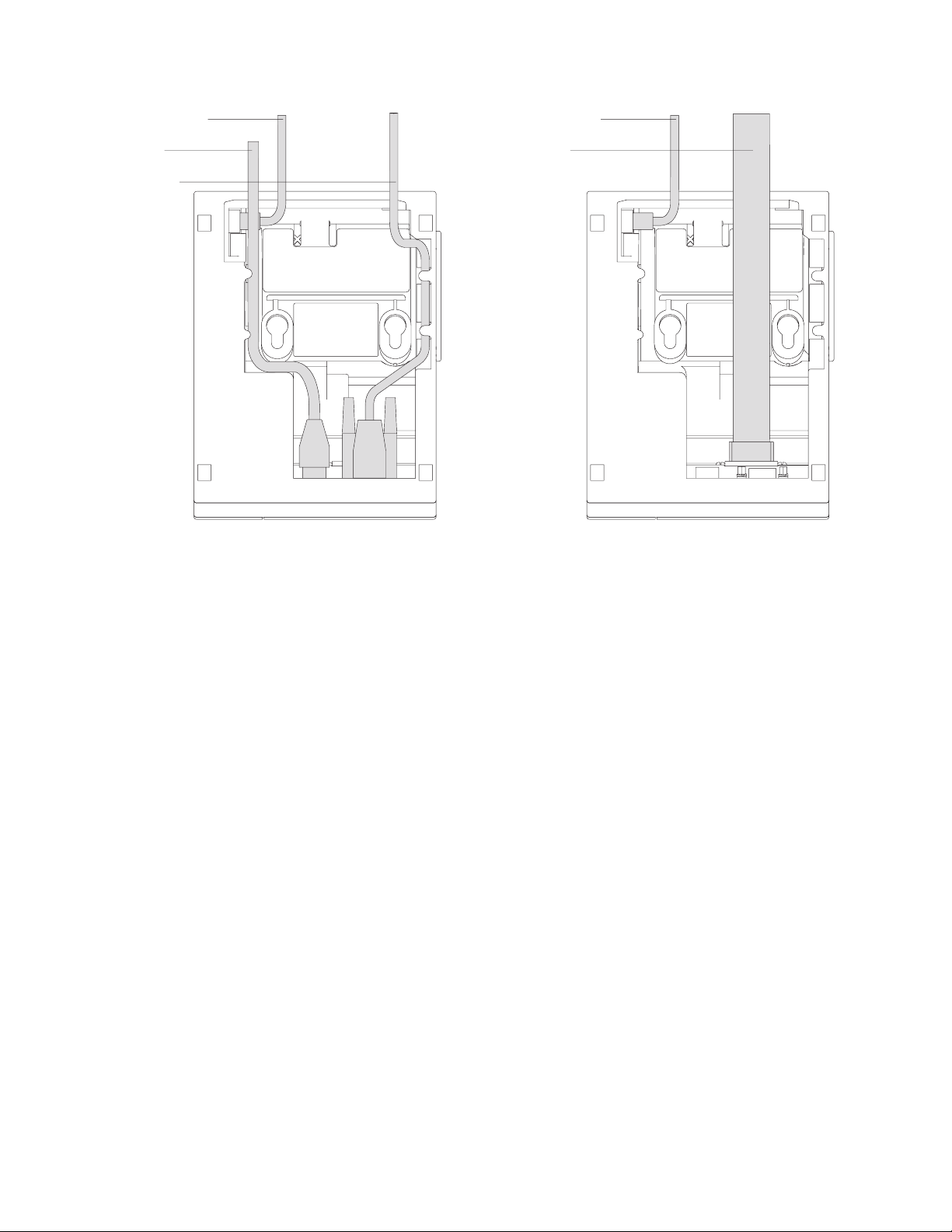
5. For single-station printers, route any power cord and cables as shown in
Figure 8 on page 20.
Chapter 2. Installation instructions 19
Page 42
Updated April 2, 2009
Cash drawer cable
Power cord
EIA-232 cable
Figure 8. EIA-232 and RS-485 cable routing for single-station SureMark printers
Cash drawer cable
RS-485 cable
6. Connect any other signal cables for I/O devices to the correct ports.
7. Check that all signal cables are installed and seated in the correct ports.
8. If you are installing the printer on an integrated unit:
a. Pull out the locking lever at the left side of the system unit. (wide systems
only)
b. For single-station printers, place the printer in the square-shaped filler
panel.
c. Route the keyboard cable to the side of the tab as shown in Figure 13 on
page 25.
d. Route all cables attached to the printer through the center opening of the
system unit and place the printer (with its filler panel, if it is a single-station
printer) on the system unit.
e. If you have additional fillers to install, go to “Installing the fillers” on page
24.
f. Lift the system unit rear cover and attach any cables from the printer to the
system unit. (If this is a EIA-232-attached printer, reattach the brick power
cord if you had to detach it to route it through the center opening.)
9. Power on the printer by either:
v Connecting the brick power supply cable to a properly wired and grounded
power source and powering it on.
v Powering on the POS system unit for an RS-485-attached printer.
Attention: Never connect both voltage sources to the printer at the same
time, even if one of the sources is powered off. Potential system damage
could occur under these conditions.
10. For single-station SureMark printers, turn on the power on/off switch on the
printer.
20 SureMark Printers User’s Guide
Page 43

Updated April 2, 2009
11. For thermal/impact SureMark printers, locate the ribbon cartridge and install it
in the printer. (See “Ribbon loading” on page 51.) Be sure that the ribbon is
routed through the print head correctly.
12. Load the paper roll into the printer. See “Paper loading” on page 53 for
thermal/impact SureMark printers or “Paper loading” on page 71 for
single-station SureMark printers.
13. Installation is now complete. Go to Chapter 5, “Testing and problem analysis,”
on page 61 for thermal/impact printers or Chapter 7, “Testing and problem
analysis (Models TF6 and TM6),” on page 75 for single-station printers and run
the offline tests.
Installing SureMark for USB communication
1. Disconnect the power brick from the printer, if one is connected.
2. Locate the rear cable connectors on the printer.
Cash
Drawer
Por t
Figure 9. USB Ports for thermal/impact SureMark printers. (View is from the bottom rear of
the printer)
Power
Supply
Por t
Powered
USB Port
Standard
USB Port
Chapter 2. Installation instructions 21
Page 44
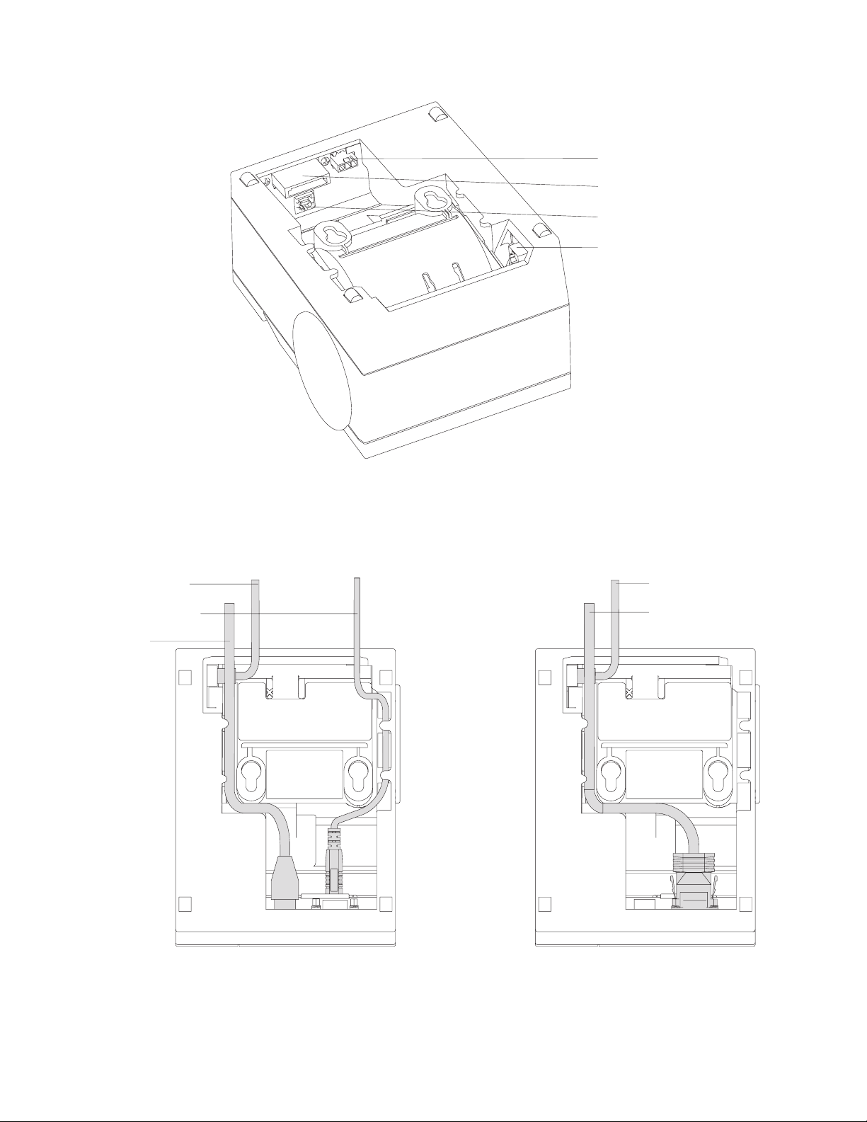
Updated April 2, 2009
Power supply port
Powered USB port
Standard USB port
Cash drawer connector
Cash drawer cable
Standard USB cable
Power cord
Figure 10. USB ports for single-station SureMark printers. (View is from the bottom rear of
the printer)
3. For single-station printers, route any power cord and cables as shown in
Figure 11.
Cash drawer cable
Powered USB cable
Figure 11. USB cable routing for single-station SureMark printers
4. Connect the USB communication cable to the correct port.
5. Connect any other signal cables for I/O devices to the correct ports.
22 SureMark Printers User’s Guide
Page 45

Updated April 2, 2009
6. Check that all signal cables are installed and seated in the correct ports.
7. If you are installing the printer on an integrated SurePOS 700 Series system:
a. For single-station printers, place the printer in the square-shaped filler
panel.
b. Route all cables attached to the printer through a rear opening of the
system unit and place the printer (with its filler panel, if it is a single-station
printer) on the system unit.
c. Make the side of the printer overlap the tab on the side of the system unit
(wide systems only).
d. If you have additional fillers to install, go to “Installing the fillers” on page
24.
e. If a fence or I/O tray is installed, lift the system unit rear cover and attach
any cables from the printer to the system unit. (If a power brick was
disconnected at the beginning of the installation or is needed because a
standard USB cable is being used, attach the power brick.)
8. If you are using a power brick, power on the printer by connecting the power
brick supply cable to a properly wired and grounded power source and
powering it on.
9. For single-station SureMark printers, turn on the power on/off switch on the
printer.
10. For thermal/impact printers, locate the ribbon cartridge and install it in the
printer. (See “Ribbon loading” on page 51.) Be sure that the ribbon is routed
through the print head correctly.
11. Load the paper roll into the printer. See “Paper loading” on page 53 for
thermal/impact SureMark printers or “Paper loading” on page 71 for
single-station SureMark printers.
12. Installation is now complete. Go to Chapter 5, “Testing and problem analysis,”
on page 61 for thermal/impact printers or Chapter 7, “Testing and problem
analysis (Models TF6 and TM6),” on page 75 for single-station printers and run
the offline tests.
Using the wall mounting feature
Because of their light weight and small footprint, the single-station SureMark
printers can be mounted on a wall. This is a useful feature when counter space is
limited.
Note: To correctly function in a wall mount, a SureMark printer must have paper
roll pivots.
To use the printer with the wall mounting feature:
1. Position the mounting bracket on a wall that has no dangerous objects, such as
electrical wires or pipes hidden beneath the wall surface.
Note: Position the bracket so that the installed printer will not extend more than
10 cm (4 in.) into a walk, hall, corridor, passageway or aisle.
2. Attach the bracket securely to the wall with four 6 mm (0.25 in.) screws. The
screws are not provided. You should use fasteners that are suitable for the type
of wall construction, such that the bracket is securely attached to the wall. For
walls that are constructed of gypsum wallboard on wood or metal studs, use
four good-quality medium-capacity or high-capacity hollow-wall anchors.
3. Route the communication cable up the wall surface or through the bracket.
Chapter 2. Installation instructions 23
Page 46

Updated April 2, 2009
4. Connect the cables to the printer.
5. Place the SureMark printer on the two bracket posts. Slide the printer down until
a click sounds.
Wall bracket
Mounting posts
Screws (not provided)
SureMark with top cover open
Figure 12. Mounting a single-station SureMark on a wall
Installing the fillers
Installing fillers for EIA-232/RS-485 printers
Notes:
1. On an integrated unit, pull out on the locking lever at the left side of system unit.
2. Ensure that the side of each filler overlaps the tab on the side of the system
unit.
To install fillers:
1. Power the system off and disconnect the EIA-232 power supply (if connected).
See Figure 5 on page 18.
2. If you have a video display on an integrated system:
a. Move the display on its arm to the side and remove any tape holding the
alignment ring.
b. Remove the knockout section of the display filler.
c. Align the display filler with the alignment ring and slide the filler onto the
ring. Press the display filler into place. See Figure 13 on page 25.
24 SureMark Printers User’s Guide
Page 47

Updated April 2, 2009
Knockout
Section
Display Filler
Printer Filler
Alignment
Ring
Display Filler
Keyboard Filler
Ta b
Locking Lever Cable
Figure 13. Installing the fillers for EIA-232/RS-485 systems
3. If you do not have a video display, place the display filler on the system unit.
Chapter 2. Installation instructions 25
Page 48

4. If you have a short keyboard, place the keyboard filler beside the keyboard. See
Figure 13 on page 25.
5. Place the printer filler beside the display filler. Make sure you route the printer
cable to the side, as shown in Figure 13 on page 25.
Installing fillers for USB printers
1. Disconnect the power brick from the printer (if connected).
2. Place the display filler appropriate for the video display on the system unit. See
Figure 14 on page 27.
3. If you have a short keyboard, place the keyboard filler beside the keyboard. See
Figure 14 on page 27.
4. Place the printer filler beside the display filler. Make sure you route the
keyboard cable to the side, as shown in Figure 14 on page 27.
Updated April 2, 2009
26 SureMark Printers User’s Guide
Page 49

Updated April 2, 2009
Knockout
Section
Display Filler
Printer Filler
Alignment
Ring
Display Filler
KeyboardFiller
Ta b
Cable
Locking Lever
Figure 14. Installing the fillers for USB systems
Chapter 2. Installation instructions 27
Page 50

Updated April 2, 2009
Figure 15. SurePOS 500 integration
EIA-232 communication mode selections (all models except TI8, TI9, TG8, TG9)
Switch settings described in this section apply only when the printer is connected to
the system with the EIA-232 cable. The switch is accessible without removing the
printer covers. (See Figure 5 on page 18 to see how to access the switch.)
Baud rate selection
SureMark printers support two EIA-232 baud rates, 9600 and 19 200 bps. The baud
rate is selected using switch 1 on the EIA-232 settings switch. Set the switch as
follows:
Switch 1 OFF 9600 bps
Switch 1 ON 19 200 bps
The printer normally ships with switch 1 in the OFF position, which selects the 9600
bps baud rate.
EIA-232 communications protocol selection
SureMark printers support EIA-232 protocol using either DTR/DSR or XON/XOFF to
control data transmission. XON/XOFF mode uses system and printer software to
control the flow of data. This is called flow control.
Use switch 2 on the EIA-232 settings switch to select the mode. Switch settings
are:
Switch 2 OFF DTR/DSR control
28 SureMark Printers User’s Guide
Page 51

Updated April 2, 2009
Switch 2 ON XON/XOFF control (required with a 3-wire interface)
The printer normally ships with switch 2 in the OFF position, which selects
DTR/DSR control.
DTR/DSR control
DSR DSR is an output from the printer. It indicates when the printer is ready to
receive data. A DSR signal becomes inactive when the printer is not ready
to receive data (for example, at power-on reset or when its buffer is full).
DTR DTR is an input to the printer. It indicates to the printer that the system is
ready to receive data. A DTR signal becomes inactive when the system is
not ready to receive data (for example, at power-on reset or when its buffer
is full).
XON/XOFF control
XON = DC1 (X'11')
XOFF = DC3 (X'13')
During XON/XOFF control, the printer transmits an XON every 3 seconds after a
power-on reset (POR) completes to indicate the printer is ready to receive data.
When the first message is received, the printer stops transmitting the XON signal.
The printer transmits an XOFF when the EIA-232 input buffer is 80% full, after
which it transmits one XON when the buffer is 20% full.
XON/XOFF transparent mode operation: This is the default mode. See
“Message from the printer” on page 184 for the format of printer to system
messages, which include a byte count, status bytes, and optional extended status
bytes or user data.
Transparent mode should always be used when selecting XON/XOFF mode for
Models TI8 and TI9.
XON and XOFF are transmitted independently, and can occur at any point inside or
outside of messages transmitted by the printer. When a message includes optional
user data, the byte count (bytes 1 and 2) can include X'10', X'11', or X'13'. When
X'10', X'11', or X'13' occur in transparent XON/XOFF mode, the byte count is
bit-exclusive-ORed with X'21' and is prefixed by the DLE (X'10') character to
become:
Value in message Becomes
X'10' X'1031'
X'11' X'1030'
X'13' X'1032'
User data with X'10', X'11', or X'13' is also treated this way in transparent
XON/XOFF mode. The byte count is not incremented for such extra characters.
Determining XON/XOFF control: You can determine whether XON/XOFF control
is being used by sending the extended address command and checking the feature
byte, bit 3. If this bit is set, the printer is in XON/XOFF mode. (See “Extended
address command-request printer ID” on page 112.)
Disabling XON/XOFF transparent mode: You can disable transparent
XON/XOFF mode as described in “Real-time requests” on page 175. When
Chapter 2. Installation instructions 29
Page 52

Updated April 2, 2009
disabled, X'10', X'11', or X'13' can occur within messages. However, because such
values are actual count bytes or data bytes and are not XON or XOFF characters
(DLE, XON, and XOFF characters do not occur within messages), no transform
takes place. The values are not bit-exclusive-ORed with X'21' because no transform
occurs for such values within messages as it does during transparent XON/XOFF
mode. DLE, XON, or XOFF occur only before or after a message.
EIA-232 communication mode selections (Models TI8, TI9, TG8, TG9)
Settings described in this section apply only when the printer is connected to the
system with the EIA-232 cable.
Baud rate selection
You must have power ON and paper installed in the thermal print station.
1. Open both the document cover and the receipt cover.
2. Press and hold both operator buttons until the Customer Receipt (CR) light
blinks rapidly.
3. Close the Document Insert (DI) cover. This is the front cover.
4. Close the CR cover. This is the rear cover. A menu is printed on the CR paper.
5. Follow the instructions on the menu to set the baud rate and the communication
protocol. The information provided in “EIA-232 communications protocol
selection” describes the selections and their purposes.
EIA-232 communications protocol selection
SureMark printers support the EIA-232 protocol using either DTR/DSR or
XON/XOFF to control data transmission. XON/XOFF mode uses system and printer
software to control the flow of data. This is called flow control.
DTR/DSR control
DSR DSR is an output from the printer. It indicates when the printer is ready to
receive data. A DSR signal becomes inactive when the printer is not ready
to receive data (for example, at power-on reset or when its buffer is full).
DTR DTR is an input to the printer. It indicates to the printer that the system is
ready to receive data. A DTR signal becomes inactive when the system is
not ready to receive data (for example, at power-on reset or when its buffer
is full).
XON/XOFF control
XON = DC1 (X'11')
XOFF = DC3 (X'13')
During XON/XOFF control, the printer transmits an XON every 3 seconds after a
POR completes to indicate the printer is ready to receive data. When the first
message is received, the printer stops transmitting the XON signal. The printer
transmits an XOFF when the EIA-232 input buffer is 80% full, after which it
transmits one XON when the buffer is 20% full.
XON/XOFF transparent mode operation: This is the default mode. See
“Message from the printer” on page 184 for the format of printer to system
messages, which include a byte count, status bytes, and optional extended status
bytes or user data.
30 SureMark Printers User’s Guide
Page 53

Updated April 2, 2009
XON and XOFF signals are always transmitted independently and are not inside
any part of the message, including the byte count, status bytes, or user data. When
a message includes optional user data, the byte count (bytes 1 and 2) can include
X'10', X'11', or X'13'. When X'10', X'11', or X'13' occur in transparent XON/XOFF
mode, the byte count is bit-exclusive-ORed with X'21' and is prefixed by the DLE
(X'10') character to become:
Value in message Becomes
X'10' X'1031'
X'11' X'1030'
X'13' X'1032'
User data with X'10', X'11', or X'13' is also treated this way in transparent
XON/XOFF mode. The byte count is not incremented for such extra characters.
Determining XON/XOFF control: You can determine whether or not XON/XOFF
control is being used by sending the extended address command and checking bit
3 of the feature byte. If this bit is set, the printer is in XON/XOFF mode. (See
“Extended address command-request printer ID” on page 112.)
Disabling XON/XOFF transparent mode: You can disable transparent
XON/XOFF mode as described in “Real-time requests” on page 175. When
disabled, X'10', X'11', or X'13' can occur within messages. The values are not
bit-exclusive-ORed with X'21' because no transform occurs for such values within
messages as it does during transparent XON/XOFF mode.
Note: Disabling XON/XOFF transparent mode should be done with Model TI4 only.
It is not recommended with Model TI8.
USB communication mode
No switches or special commands are required for USB communication. With the
USB interface card and cables in place, the system automatically detects the printer
when it is attached and performs any necessary setup. The printer operates at data
rates up to 12 Mbps.
USB selection
USB is an industry standard communication interface. It is used to attach devices
such as printers, displays, and keyboards to personal computers or to IBM POS
systems that have USB ports. The standard USB port (with a power brick) is used
to attach the SureMark to personal computers. The powered USB port is used to
attach the SureMark to IBM POS systems. See Figure 9 on page 21 for the
thermal/impact SureMark printers and Figure 10 on page 22 for the single-station
SureMark printers.
Chapter 2. Installation instructions 31
Page 54

Updated April 2, 2009
32 SureMark Printers User’s Guide
Page 55

Updated April 2, 2009
Chapter 3. SureMark installation, service, and utility software
Software adjustments (Models TI1, TI2, TI3, TI4, TI8, TI9, TG3, TG4, TG8, and
TG9) ............................34
Offline configurations for Models TI8, TI9, TG8, TG9 ..........34
Using the IBM Diagnostics for the POS Systems and Peripherals (all models
except Models TI1 and TI2) ..................34
Using the reference/service diskettes (Models TI1 and TI2) .......35
4610 fonts and logos utilities ....................37
Utility diskette ........................37
IBM Diagnostics for POS Systems and Peripherals package (all models
except TI1 and TI2) .....................37
Proportional font conversion utility ..................37
Firmware update ........................37
Using a firmware update diskette (Models TI1 and TI2 only) .......38
Using POSS for Windows to update SureMark printer firmware (RS-485 and
USB only) .........................39
Using JavaPOS for Windows to update SureMark printer firmware (EIA-232,
RS-485, and USB)......................39
Automatic update ......................39
Command line utility (AipFlash46s) ...............40
Updating SureMark firmware using temporary EIA-232 attachment .....40
Limitation on updating firmware ..................41
Emulating the IBM Model 3 or Model 4 printers .............41
Limitations for emulation ....................41
Printing saved data ......................41
Printing buffer data on thermal/impact printers ...........42
Printing buffer data on single-station printers ............42
Emulating an Epson single-station printer (single-station only) .......43
Enabling Epson emulation....................43
Limitations for Epson emulation ..................43
MICR data parser sample code (Models TI2, TI4, TI8, TI9, TG4, TG8, and TG9
only) ............................44
Resources on the Internet .....................44
This chapter describes how to make software adjustments using either the IBM
Diagnostics for POS Systems and Peripherals (POSS for Windows, RS-485 and
USB only) or diskettes and other resources that are available from the Retail Store
Solutions Web site. See “Resources on the Internet” on page 44 for more
information.
© Copyright IBM Corp. 1997, 2006 33
Page 56

Updated April 2, 2009
Software adjustments (Models TI1, TI2, TI3, TI4, TI8, TI9, TG3, TG4, TG8, and TG9)
When a printer main logic card is replaced, the following software adjustments
should be run:
v Character alignment procedure (see Figure 16 on page 36)
v Document insert front load print line adjustment (see Figure 16 on page 36)
v Document landscape adjustment (see Figure 16 on page 36)
v Store printer's serial number
v Update the firmware to the latest level
v Reset printer statistics
v Scanner calibration (Models TI8, TI9, TG8, TG9)
v 4610 Model configuration (If the configuration is not set correctly, the printer may
act unpredictably.)
Notes:
1. Cards for TI1s and TI2s are set up as TI2s.
2. Cards for Tx3s and Tx4s are set up as Tx4s.
3. Cards for Tx8s and Tx9s are set up as Tx8s.
Depending on your SureMark model, you can use the following to make software
adjustments to the printer:
v Offline configuration for Models TI8, TI9, TG8, TG9
v IBM Diagnostics for POS Systems and Peripherals (except Models TI1 and TI2)
v Reference/service diskettes (Models TI1 and TI2 only)
Offline configurations for Models TI8, TI9, TG8, TG9
You must use the calibration procedure to calibrate the scanner.
You must have power ON and paper installed in the thermal print station.
1. Open both the document cover and the receipt cover.
2. Press and hold both operator buttons until the Customer Receipt (CR) light
blinks rapidly.
3. Close the Document Insert (DI) cover. This is the front cover.
4. Close the CR cover. This is the rear cover. A menu is printed on the CR paper.
5. Follow the instructions on the menu to:
v set the EIA-232 parameter
v set the baud rate
v set the communication protocol
v invoke scanner calibration
v set the 4610 model configuration
The information provided in “EIA-232 communications protocol selection” on
page 30 describes the selections and their purposes.
Using the IBM Diagnostics for the POS Systems and Peripherals (all models except Models TI1 and TI2)
The IBM Diagnostics for the POS Systems and Peripherals is a GUI-based
diagnostic package on a USB flash drive. It is used to troubleshoot hardware
problems, and it includes these 4610 printer utilities:
34 SureMark Printers User’s Guide
Page 57

Updated April 2, 2009
v Microcode update
v Logo download
v Message download
v Printer Configuration Utility, which includes:
– Scanner calibration
– Print current adjustment values (see Figure 16 on page 36)
– Character alignment procedure (see Figure 16 on page 36)
– Backlash adjustment (document landscape, see Figure 16 on page 36)
– DI front load print line adjustment (see Figure 16 on page 36)
– Set serial number
– Reset printer statistics
– Set printer type (4610 model configuration)
Using the reference/service diskettes (Models TI1 and TI2)
1. Load the reference/service diskette. See the hardware service manual for your
system for reference/service diskette procedures.
2. Select Test Menu.
3. Select Run POS Device Tests for an RS-485 connection. Select EIA-232 4610
Printer Test for an EIA-232 connection.
4. If another system is attached, select the system whose printer you want to
adjust. This is unnecessary when there is no other system attached.
5. Select Printer Utilities.
6. Select the adjustment you want to make from the menu.
v Print current adjustment values: see Figure 16 on page 36.
v Character alignment procedure: see Figure 16 on page 36.
v DI front load print line adjustment: see Figure 16 on page 36.
v Document landscape adjustment: see Figure 16 on page 36.
v Engineering use only
v Change 4610 Model Configuration
v Reset printer statistics
Note: Because the first four adjustments affect only the document insert
station, they are not displayed as selectable options if the printer is a
single-station SureMark.
Chapter 3. SureMark installation, service, and utility software 35
Page 58

CURRENT ADJUSTMENT VALUES
H 5 = Character alignment
TL5 = Top line front insert
BL3 = Bottom line top insert
CHARACTER ALIGNMENT PROCEDURE
Updated April 2, 2009
TL1
TL2
TL3
TL4
TL5
TL6
TL7
TL8
TL9
Measure from the top edge of this
paper to the top of each print line.
Press the key (1-9) that corresponds
to the print line that is closest to 5MM.
Press the key (1-9) that corresponds
to the pair of H's that appear to be
most aligned
5 = selected line
Figure 16. Adjustment and alignment printouts
7. Follow the instructions that are printed on the printer or displayed on the screen.
8. Press S1 (Esc on the Enhanced A/N Keyboard) to return to the previous menu.
36 SureMark Printers User’s Guide
Page 59

Updated April 2, 2009
4610 fonts and logos utilities
There are utilities available on the Retail Store Solutions Web site. Depending on
your model, you may either use the utility diskette or use the IBM Diagnostics for
POS Systems and Peripherals package.
The utility program allows you to perform the following functions:
v Update printer firmware
v Configure the printer model
v Create, edit, and download user-defined character fonts, logo images, and
messages
v Download proportional fonts (not supported for Models TI1 and TI2)
v Convert fonts and logo files from impact to thermal
Utility diskette
This utility is for both EIA-232 and RS-485 operation. You can download the utility
from the Retail Store Solutions Web site. See “Resources on the Internet” on page
44 for more information.
From the same Web site, you can also download the following sample files for use
with the utility program:
v User-defined characters file
v Message file
v Logo file
IBM Diagnostics for POS Systems and Peripherals package (all models except TI1 and TI2)
This utility is for EIA-232, RS-485, and USB operation. Refer to the README file in
this package for details on how to run these utilities.
Proportional font conversion utility
As part of its support for proportional fonts, IBM provides three TrueType fonts and
a utility that you can use to convert the fonts to files that the SureMark printer can
use.
The application and instructions for downloading the converted fonts are available
from the Retail Store Solutions Web site. See “Resources on the Internet” on page
44 for more information.
Note: You might have TrueType fonts other than those supplied by IBM on your
system. Before using the conversion utility to convert and download any
non-IBM fonts for use by the SureMark printer, you must confirm that you
have received authorization from the owner of the fonts to convert and
download the fonts.
Firmware update
The SureMark printer has the capability to receive SureMark firmware updates from
the host system unit to which it is attached for either RS-485-attached,
EIA-232-attached, or USB-attached SureMark printers.
The following mediums can be used to update the SureMark firmware:
v Firmware update diskettes
Chapter 3. SureMark installation, service, and utility software 37
Page 60

v POSS for Windows 4610 Printer Firmware Update Program
v Alternative 4610 firmware update method via EIA-232 attachment cable
Use the appropriate procedure that follows to update the SureMark firmware, after
downloading the latest level software from the Retail Store Solutions Web site (see
“Resources on the Internet” on page 44).
Using a firmware update diskette (Models TI1 and TI2 only)
Use a firmware update diskette to update the firmware in configurations when the
SureMark is attached by either an EIA-232 or RS-485 cable and when the system
has a floppy diskette drive, a PC keyboard, and display.
1. Download the latest level of firmware update diskette from the Web (see
“Resources on the Internet” on page 44). You can select from several update
methods, including attended, unattended, and automatic.
2. Insert the firmware update diskette in drive A.
3. Power on the system unit that has the SureMark attached by either an EIA-232
or RS-485 cable.
4. Select RS-485 or EIA-232 connection.
5. Follow the messages displayed to complete the firmware update.
a. Press Enter (OK) at the logo screen to proceed.
b. Choose connection type (RS-485 or EIA-232). For EIA-232 connections,
also make the following selections (refer to the communications mode
selections switches, located on the bottom rear of the SureMark printer, to
determine the following selections):
v Communications port (COM1, COM2, COM3, COM4)
v Baud rate (9600 or 19 200 bps)
v Control Flow (DTR/DSR or XON/XOFF)
c. Press Enter (OK) to proceed.
d. Press F10 (Menu).
e. Select O (Operations).
f. Select A (Advanced Options).
g. Select U (Update Firmware).
h. Press Enter twice to select the desired firmware image file (usually only the
latest firmware image file is available for selection).
i. Press Enter (YES) again to commit to firmware update.
j. The Information screen will display the update percent completed.
Updated April 2, 2009
6. After the firmware update is complete, the SureMark printer will be reset.
a. Press Enter (OK) to confirm.
b. Press Alt+X (Exit).
c. Press Enter to exit.
7. Remove the diskette from drive A.
8. Press Ctrl+Alt+Del to reboot the system.
38 SureMark Printers User’s Guide
Note: The SureMark flash update will take several minutes. Do not power off
the host system or the SureMark printer after the update has started.
Page 61

Updated April 2, 2009
Using POSS for Windows to update SureMark printer firmware (RS-485 and USB only)
Windows users with SureMark printers can use the POSS for Windows 4610 Printer
Firmware Update program (AIPFLD46.EXE) to update SureMark firmware. For
additional information, refer to the POSS Programming Reference and User’s
Guide.
Note: POSS Suite V1.0.0 or greater is required to use this utility.
1. Download the latest SureMark firmware update image file from the Web. The file
is:
v AIP46MC.HEX for Models TI1 and TI2
v AIP46MCH.HEX for Models TI3, TI4, TG3, and TG4. This file is also for
single-station printers with 512 KB or 8 MB of memory
v AIP46MCD.HEX for Models TI3, TI4, TG3, TG4, TF6, and TM6 with the 2 MB
memory option.
v For Model TI8, see the IBM Retail Store Solutions Web site at
http://www.ibm.com/solutions/retail/store/support/.
2. Copy the latest SureMark firmware update image file to the C:\POS\BIN
directory. Because the file in the directory is more current than the old file, the
firmware will be automatically updated when the system is powered off and
back on.
3. To update the firmware manually, enter the AIPFLD46.EXE -S slot_number -P
port_number -F microcode_file [-Q] command to update the SureMark firmware,
where:
slot_number
SureMark slot number, usually = 1. The slot number must be specified
with decimal values only; hexadecimal values are not accepted.
port_number
SureMark port number specified with a decimal value, usually = 17
microcode_file
Either C:\POS\BIN\AIP46MC.HEX, C:\POS\BIN\AIP46MCH.HEX, or
C:\POS\BIN\AIP46MCD.HEX
-Q (Optional) Quiet mode installation (no progress information)
4. The SureMark flash update will take several minutes.
Using JavaPOS for Windows to update SureMark printer firmware (EIA-232, RS-485, and USB)
The firmware can be updated by automatic update or by the command line utility.
Automatic update
Follow these steps to update the POSPrinter firmware for Linux:
1. Obtain the appropriate flash file from the Web:
v AIP46MCH.HEX for 4610 Tx3, Tx4 and Tx6
v AIP46MCD.HEX for 4610 TI5 and TI7
v AIP46TI8.HEX for TI8 and TI9
Go to http://www.ibm.com/solutions/retail/store/support/. Click the links to
JavaPOS POSPrinter support.
2. Create an rs485 directory as follows:
Chapter 3. SureMark installation, service, and utility software 39
Page 62

Updated April 2, 2009
v For Linux, go to the directory /opt/ibm/javapos/flash on the target system and
create an rs485 directory. This is done as shown in the following example:
% cd /opt/ibm/javapos/flash
% mkdir rs485
v For Windows, go to the directory root install directory\IBMJPOS\res\
flash on the target system and create an rs485 directory. This is shown in
the following example, where the root install directory is C:\POS.
C:\> cd\POS\IBMJPOS\res\flash
C:\> mkdir rs485
3. Place the correct flash file (ensure it matches the printer type) into the new
directory.
4. Make sure the printer is attached and reboot the system. (The flash will take a
few minutes to complete during boot-up.)
Command line utility (AipFlash46s)
The IBM 4610 printer firmware can be downloaded using a command utility. The
syntax for the utility is java com.ibm.jpos.util.flash.AipFlash46s [param]
[RS-485_flash_filename].
Valid values for the variables are:
param -e: flash printer EC level
RS-485_flash_filename
Includes the absolute path name of the flash file (for example:
/opt/ibm/javapos/flash/aipmch46.hex)
Updating SureMark firmware using temporary EIA-232 attachment
To use the firmware update diskettes to update SureMark firmware for
configurations that do not have a floppy diskette drive and PC display and
keyboard, you must provide a temporary EIA-232 attachment to a host PC that
does have a floppy diskette drive.
Note: A 4610 firmware update diskette at V3.10 or greater is required to use this
utility.
Before starting the firmware update, you must obtain the following parts:
v EIA-232 attachment cable, either 2 meters in length (P/N 40N4780) or 4 meters
in length (P/N 86H2195).
v SureMark Power Supply for EIA-232 configurations only (P/N 40N5051).
If the SureMark is currently attached to a host system unit that does not support a
floppy diskette drive, use the following procedure to temporarily connect the printer
to a host PC that has a floppy diskette drive, EIA-232 port, PC keyboard and
display.
1. Disconnect the SureMark (RS-485 #7) attachment cable and temporarily
connect a EIA-232 attachment cable to the SureMark.
2. Connect the SureMark via the EIA-232 port connector to an alternate host PC
that has a floppy diskette drive.
3. Follow the procedure in “Using a firmware update diskette (Models TI1 and TI2
only)” on page 38 to complete the SureMark firmware update.
4. Reconnect the SureMark to the original host system unit using the original
attachment cables.
40 SureMark Printers User’s Guide
Page 63

Updated April 2, 2009
Limitation on updating firmware
The following limitation must be considered when updating firmware on the
SureMark printer:
v SureMark firmware update can not be performed if the printer currently has
Model 4 emulation enabled. If emulation is enabled, temporarily disable Model 4
emulation, then start the SureMark firmware update. After the firmware update is
complete, re-enable Model 4 emulation. See “Emulating the IBM Model 3 or
Model 4 printers” for additional information.
Emulating the IBM Model 3 or Model 4 printers
Note: All SureMark firmware levels for Models TI3, TI4, TG3, TG4, TF6 and TM6
support emulation; no other models support this emulation.
It is possible to emulate the IBM Model 3 or Model 4 printer with the SureMark
printer. You must change the configuration to enable the SureMark to emulate the
Model 3 or Model 4 printers.
To set up the Model 3 or Model 4 emulation, use the IBM Diagnostics for POS
Systems and Peripherals package. Refer to the README file in that package for
the Change Printer Type utility.
Note: Model 3 and Model 4 emulation is not supported in firmware levels 43 and
greater. For the latest level of firmware that includes Model 3 and 4
emulation please use the Model 4 Emulation Support diskette.
Limitations for emulation
The following limitations must be considered when using the SureMark printer to
emulate the Model 3 or Model 4 printer.
v Printing the face of checks requires application changes (franking the back of
checks should not).
v Printing wide documents may require changes. The document station on the
Model 4 printer supports 86 characters, the SureMark supports 47 characters.
v Journal commands can be ignored or stored in the flash memory of the printer.
This needs to be decided when the printer is initially configured.
v There is no top document registration (documents must be inserted from the
front).
v User-defined special characters are not supported.
v Because SureMark Models TF6 and TM6 do not have a document insert station,
they do not emulate document station commands.
v Emulation mode does not support the Model 4A double-byte character set.
v For RS-485, emulation mode is currently only supported on 4690 OS and DOS
systems. For USB, emulation mode is currently only supported on 4690 OS.
Emulation is not supported for EIA-232.
v On the DI portrait station, 1 inch = 51 motor steps (1 mm = 2 steps). This is
different from a Model 3 or 4 printer, where 1 inch = 48 steps.
Printing saved data
When the printer is offline in Model 3 or 4 emulation mode and the option for
storing data to the printer is selected, it is possible to fill up the printer flash
memory. When the memory is full, a printer error indicates the journal station is out
Chapter 3. SureMark installation, service, and utility software 41
Page 64

Updated April 2, 2009
of paper. You can empty the printer buffer by printing out the data that is stored in
the flash memory. The data prints on the customer receipt station. The data in the
buffer is erased only after the last line of data is printed.
Note: If the SureMark has the 2 MB option installed, up to three rolls of paper
might be needed to print all the electronic journal data.
You can upload an electronic journal while in Model 4 emulation mode. See
Appendix E, “Uploading electronic journal data,” on page 187 for detailed
information.
Printing buffer data on thermal/impact printers
To print the buffer data from the beginning:
1. Press and hold both buttons. When the printer ready indicator begins blinking,
release both buttons.
2. Press and release both buttons again.
Notes:
1. If the SureMark printer encounters an error (for example, the paper runs out or
the cover is opened) while printing the data, the data remains intact.
2. To stop printing the data, open and close the ribbon cover. When you are ready
to print the data, use the procedure above to restart printing from the beginning.
3. To stop printing and restart at the current position, open and close the paper
cover. Printing immediately restarts.
Printing buffer data on single-station printers
To print the buffer data from the beginning:
1. Open the top cover. The LED will flash quickly.
2. Press and hold the paper feed button for 5 seconds.
Note: The paper feed button is the small button next to the LED.
3. The LED will show one short blink, accompanied by a beep, followed by a 1
second pause.
4. Press and hold the paper feed button for 5 seconds.
5. The LED will change to a long blink. The beeper will sound continuously.
6. Close the cover to begin printing the electronic journal data.
Notes:
1. If the SureMark printer encounters an error (for example, the paper runs out or
the cover is opened) while printing the data, the data remains intact.
2. To stop printing the data, open the top cover, turn the printer power switch OFF,
turn the printer power switch back ON, and close the top cover. When you are
ready to print the data, use the procedure above to restart printing from the
beginning.
3. To stop printing and restart at the current position, open and close the top cover.
Printing immediately restarts.
4. To return the printer to normal mode, press and release the paper feed button a
third time before closing the top cover.
42 SureMark Printers User’s Guide
Page 65

Updated April 2, 2009
Emulating an Epson single-station printer (single-station only)
Emulation of an Epson single-station printer is supported on the single-station
SureMark printers. See Appendix G, “Emulation support for Epson single-station
printer,” on page 193.
Enabling Epson emulation
To enable emulation of an Epson single-station printer on a single-station SureMark
printer, you must set switch 3 on the main logic card. See Figure 17 for the location
of the switch.
OFF
4
3
2
1
EIA-232 mode switches
Figure 17. Switch for Epson emulation
Limitations for Epson emulation
The following limitations must be considered when using a single-station SureMark
printer to emulate an Epson single-station printer:
v Logos and downloadable characters are supported in emulation mode. However,
because the Epson printer prints at 180 dpi and the SureMark prints at 200 dpi,
the emulated printout will be smaller.
v Emulation of page mode is not supported on the SureMark.
v Epson supports the Select paper sensor to stop printing command. IBM does not
support a low paper sensor.
v In order to implement fixes, new functionality, and other improvements, new
releases of printer microcode are routinely published. It is advisable that you run
the most recent version of firmware on the printer; however, the 4610 firmware
can not be updated when running in Epson emulation mode. Therefore, you must
first switch the printer to native mode, to upgrade the microcode.
Cash drawer connector
Chapter 3. SureMark installation, service, and utility software 43
Page 66

Updated April 2, 2009
MICR data parser sample code (Models TI2, TI4, TI8, TI9, TG4, TG8, and TG9 only)
The MICR data parser download package includes:
v Sample source code (in C) that contains algorithms for parsing MICR data from a
check.
v An exception data file that is used with the parsing code. You can edit this file to
add new check formats, if necessary.
Refer to the README file in this download package for additional information.
Resources on the Internet
The IBM Retail Store Solutions Web site at http://www.ibm.com/solutions/retail/store/
support/ contains publications for the SureMark printer. The Web site also provides
access to diskettes, drivers, and miscellaneous documentation, such as README
files and information about OEM papers that have been certified.
Select IBM SureMark Printer. The displayed page contains links both to
documentation and to diskettes and drivers that you can download for the SureMark
printers.
44 SureMark Printers User’s Guide
Page 67

Updated April 2, 2009
Part 2. Models TI1, TI2, TI3, TI4, TI8, TI9, TG3, TG4, TG8, TG9
This part contains operational, testing, and problem determination information for
the thermal/impact SureMark printers Models TI1, TI2, TI3, TI4, TI8, TI9, TG3, TG4,
TG8, TG9. All references to Model TI3 pertain to Model TG3, references to TI4
pertain to Model TG4, and so on.
© Copyright IBM Corp. 1997, 2006 45
Page 68

Updated April 2, 2009
46 SureMark Printers User’s Guide
Page 69

Updated April 2, 2009
Chapter 4. Operation
Operating controls and indicators ..................47
Ribbon loading .........................51
Paper loading .........................53
Clearing jams in the check flipper area ................55
%%
Operating controls and indicators
MICR reader read head cleaning ..................56
Thermal print head cleaning ....................57
Document scanner cleaning (Model TI8, TI9, TG8, TG9) .........59
Document scanner calibration (Models TI8, TI9, TG8, TG9) ........60
Note: All covers must be installed on the SureMark printer during operation.
There are two triangular-shaped buttons and two LED indicators located on top of
the printer. The buttons serve multiple functions.
When the topmost indicator is on continuously, the printer is powered ON and ready
for printing. When the indicator blinks, one of the following conditions exists:
v The printer is out of paper.
v The cover is open.
v The printer is offline.
v The printer has a nonrecoverable home error.
The second LED is the Document Present indicator. It lights when a document is
inserted far enough into the document insert station to reach the DI sensor. When
this LED blinks, the DI station is waiting for you to insert a document.
The topmost button is the customer receipt paper feed button. Press this button to
advance the CR paper. The lower button is the document feed button. Press this
button to advance the document.
If you press both buttons at the same time and then release them, the document
insert throat opens. The throat must be open to insert a document from the side.
Press and then release both buttons again to close the throat.
Both buttons are also used to test the printer. See “Offline tests” on page 62 for
additional button functions.
Paper Cover
Customer Receipt Printer
Ribbon Cover
Document Printer
Figure 18. SureMark printer indicators, controls, and printing stations (Models TI1, TI2, TI3,
TI4, TI8, TI9, TG3, TG4, TG8, and TG9)
Printer Ready LED
Customer Receipt Feed Button
Document Present LED
Document Feed Button
The printer is capable of printing verification information on a check and printing
information on an inserted document. Figure 19 on page 48, Figure 20 on page 48,
and Figure 21 on page 49 show the correct positioning of checks and documents in
© Copyright IBM Corp. 1997, 2006 47
Page 70

Updated April 2, 2009
SureMark printers with impact (document insert) stations. Those figures also show
how to side load a document to align it exactly where you want it to be printed.
Notes:
1. When side loading a Model TI8 or TG8, the document must be placed lower
than with the other models.
2. Side loading is not available with Models TI9 and TG9.
Insertion of Check
for MICR Reading
Insertion of Check
for Printing the Face
and Franking
PayToThe
Order Of
Endorse Here
For Financial Usage Only
Do Not Sign / Write / Stamp BelowThis Line
Federal Reserve Bank Regulation CC
Memo
041117847096 095867238671 4001
Figure 19. Inserting checks for all models except TF6 and TM6
Insertion of Document
(Front Load)
4001
19
$
Dollars
Figure 20. Inserting checks or documents in a Model TI2, TI4, TI8, TI9, TG4, TG8, or TG9
printer
48 SureMark Printers User’s Guide
Page 71

Updated April 2, 2009
Insertion of Document
(Side Load)
Print Position
Figure 21. Inserting checks or documents in a Model TI2 or TI4 printer
Figure 22. Side insertion of documents in a Model TI8 printer
Figure 23 and Figure 24 on page 50 show the printable area on an inserted
document for both portrait and landscape.
Chapter 4. Operation 49
Page 72

Updated April 2, 2009
Figure 23. Printable area of an inserted document (portrait)
Figure 24. Printable area of an inserted document (landscape)
50 SureMark Printers User’s Guide
Page 73

Updated April 2, 2009
Ribbon loading
1. Open the ribbon cover. As the cover is opened, the print head moves to a
position where you can easily load a ribbon.
Figure 25. Opening the ribbon cover
2. If there is already a ribbon cartridge installed, remove it by lifting it straight up.
Note: You might need to grasp the body of the cartridge rather than the top to
remove it.
Figure 26. Ribbon cartridge loading
Chapter 4. Operation 51
Page 74

Updated April 2, 2009
3. Maintain ribbon tension by turning the ribbon cartridge knob as shown in
Figure 26 on page 51. Lower the cartridge into position until the notches on its
sides snap into place on the printer guides. Once the cartridge is in place, turn
the knob until the ribbon slides into place between the print head and the ribbon
shield. See Figure 27 for correct ribbon positioning.
Ribbon Shield
Printhead
Correct
Figure 27. Ribbon path around the print head
4. Close the ribbon cover.
Not Correct
52 SureMark Printers User’s Guide
Page 75

Updated April 2, 2009
Paper loading
1. Open the paper cover.
2. If there is any unused paper or if there is an empty paper roll core in the paper
roll bucket inside the printer, remove it before inserting a new paper roll. You
can throw the core in the trash can.
Note: Refer to the label on the inside of the paper cover for a diagram of how
to load paper.
Figure 28. Paper cover (Models TI1, TI2, TI3, TI4, TI8, TI9, TG3, TG4, TG8, and TG9)
3. See Figure 29 on page 54 and place the paper roll into the paper roll bucket as
shown. The leading edge of the paper should come from the direction of the
front of the printer and go across the top of the roll as shown in the diagram. If
it feeds from the bottom of the roll, nothing will be printed on the paper.
Note: The thermal print head will not print on paper with glue on it. If the new
paper roll was sealed by glue, tear off the 6 to 8 inches of paper with
glue on it before loading it.
Chapter 4. Operation 53
Page 76

Updated April 2, 2009
Not Correct Correct
Thermal
Platen
Figure 29. Paper loading path (Models TI1, TI2, TI3,TI4, TI8, TI9, TG3, TG4, TG8, and TG9)
Paper Roll
Paper
Roll Core
4. See Figure 29. Place the leading edge of the paper over the metal guide.
5. Close the paper cover.
6. Press the customer receipt feed button to advance the paper, to verify that the
paper is feeding correctly. Feed 30 cm (about 1 ft.) of paper through to test for
correct alignment.
Attention: Do not pull the receipt paper out of the printer with the paper access
cover closed. This disengages the paper feed. The paper feed motor must then
catch up before the printer can feed the paper, which causes missing lines or partial
lines of print. Use the customer receipt feed button to advance the receipt and all
lines will print.
54 SureMark Printers User’s Guide
Page 77
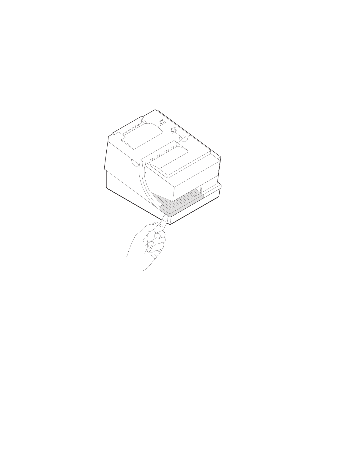
Updated April 2, 2009
Clearing jams in the check flipper area
This procedure is for the SureMark printer Models TI2, TI4, TI8, and TI9 (MICR
Reader and Check Flipper features) only.
If a check jams in the Check Flipper mechanism:
1. Lift up the left front corner of the lower document insert cover and pull the cover
from the printer. (See Figure 30.)
Figure 30. Removing the lower document insert cover
2. The action you take in this step depends on whether the document is visible
and can be removed:
v If you can remove the document:
a. Remove the document.
b. Replace the lower document insert cover.
c. You are finished with this procedure.
v If you can not remove the document, continue with Step 3.
3. Lift up the tab on the left side of the check flipper cartridge and remove the
assembly from the printer. (See Figure 31 on page 56.)
Note: For printers with a powered flipper (Models TI8, TI9, TG8, TG9) the
cartridge is attached to the printer with an electrical cable and can not be
removed. Simply raise the front edge of the cartridge to remove a
jammed document underneath.
Chapter 4. Operation 55
Page 78

Updated April 2, 2009
Figure 31. Removing the check flipper cartridge (except Models TI8, TI9)
4. Reach inside the document insert station and carefully remove the jammed
check.
5. Reinstall the check flipper cartridge and the lower DI cover.
MICR reader read head cleaning
%
%
%
%
%
%
%
%
%
%
%
The MICR reader read head should be cleaned after 10000 checks are processed
or every 3 months, as required.
1. Open the ribbon cover.
2. Move the impact printhead to its rightmost position.
3. Rotate the document sensor assembly towards the front of the printer to expose
the MICR read head.
4. Use a cotton swab that is lightly soaked with alcohol to wipe any residue or dirt
from the MICR read head surface.
5. Gently return the document sensor assembly to its original position.
56 SureMark Printers User’s Guide
Page 79
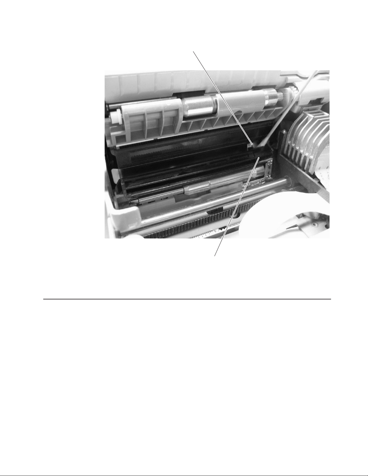
Updated April 2, 2009
%
MICR Read Head
%
%
%
Figure 32. MICR reader read head
Thermal print head cleaning
The thermal print head can be cleaned whenever print quality deteriorates.
1. Open the paper cover.
2. Using a cotton swab soaked in isopropyl alcohol, gently wipe the print head
several times on its print line and on the surrounding area. See Figure 33 on
page 58.
Document Sensor Assembly
Chapter 4. Operation 57
Page 80

Detailed View of Thermal Printhead
Updated April 2, 2009
Thermal Print Line
Paper Cover
Figure 33. Print head and print line area (Models TI1, TI2, TI3, TI4, TI8, TI9, TG3, TG4, TG8, and TG9)
3. Wipe off any residual alcohol with a dry swab.
If print quality does not improve after cleaning the thermal print head, call for
service.
58 SureMark Printers User’s Guide
Page 81

Updated April 2, 2009
Document scanner cleaning (Model TI8, TI9, TG8, TG9)
The scanner surface should be cleaned after 10 000 documents or every three
months or whenever image quality deteriorates.
1. Open the ribbon cover. See Figure 34.
Registration Plate
Print Head
Scanner
Surface
Figure 34. Scanner and print head location (Model TI8, TI9, TG8, TG9)
2. Move the impact print head to its rightmost position, as shown.
3. Rotate the scanner registration plate 180° up to expose the glass scanner
surface. See Figure 34.
4. Use a cotton swab that is lightly soaked with alcohol to wipe any residue from
the scanner glass surface.
5. Gently return the scanner registration plate to its original position.
6. The scanner should be recalibrated after it has been cleaned. See “Document
scanner calibration (Models TI8, TI9, TG8, TG9)” on page 60.
Ribbon Access Cover
Chapter 4. Operation 59
Page 82

Document scanner calibration (Models TI8, TI9, TG8, TG9)
The printer must have power ON. Use a clean sheet of white copier paper (not
recycled paper) as the calibration target. Fold the paper in half. (Optional: cut paper
to 4.25 in. wide.)
1. Always begin by making sure the scanner window is clean.
2. Put paper in the CR station (paper will be used for printing in later step).
3. Insert the target paper into the document insert station as you would insert a
check. The folded edge should be up (or inserted first) and the right edge
should be against the right side of the paper path. Press the DI button to
automatically advance the paper to the ready position.
4. Enter offline mode by doing the following:
a. Open the CR cover and the DI cover.
b. Press and hold both buttons until the LED flashes rapidly.
c. Close the DI cover.
d. Close the CR cover.
5. Follow the directions that are printed in the CR station to perform the calibration.
6. Remove the target paper when complete.
7. Power the printer OFF and then ON for the changes to take effect.
Updated April 2, 2009
60 SureMark Printers User’s Guide
Page 83

Updated April 2, 2009
Chapter 5. Testing and problem analysis
DANGER
To avoid a shock hazard, do not connect or disconnect any cables
or perform installation, maintenance, or reconfiguration of this
product during an electrical storm.
DANGER
To avoid shock hazard:
The power cord must be connected to a properly wired and
earthed receptacle.
Any equipment to which this product will be attached must also
be connected to properly wired receptacles.
Note: For translations of these safety notices, see IBM Safety Information—Read
Testing the printer
When you power ON the SureMark printer, it runs a power-on self-test (POST). If
the POST finds no errors, the printer is ready for operation. Follow this procedure to
determine if there are errors.
Note: Never connect or disconnect the printer when power is applied (when LEDs
1. If the printer is powered ON, power OFF the printer and power it ON again.
This First, GA27-4004.
are ON).
v If the printer is attached to the system with the EIA-232 cable or the standard
USB cable with a power brick, disconnect the power cord, then reconnect the
power cord to a properly wired and grounded power source.
v If the printer is attached to the system with the RS-485 cable, power OFF the
POS system, and then power ON the system, which also powers ON the
printer.
v If the printer is attached to the system with a powered USB cable, the USB
attached printer can be hot-plugged.
© Copyright IBM Corp. 1997, 2006 61
Page 84

Figure 35. Printer buttons
Updated April 2, 2009
Printer Ready LED
Customer Receipt Feed Button
Document Present LED
Document Feed Button
2. Check the status of the Printer Ready indicator:
Printer ready indicator ON:
The power-on self-test completed successfully.
Printer ready indicator OFF or blinking:
The POST failed.
3. If the POST fails or if you suspect problems with your system, see “Problem
determination” on page 67.
4. See “Offline tests” and run the offline tests. If the offline tests fail or you suspect
problems with your system, see “Problem determination” on page 67.
Offline tests
The following offline tests are used as diagnostic tools to ensure the printer is
operating correctly.
Customer receipt test
1. Press and hold both buttons to enter offline mode. When the printer ready
indicator begins blinking, release both buttons.
2. Press and release the customer receipt feed button to start this test.
3. See Figure 36 on page 64 and verify that your printer has printed correct
information for your model and configuration:
v MICR reader enabled and check flipper enabled (Model TI2, TI4, TI8, TI9,
TG4, TG8, TG9)
v Optical scanner enabled (Model TI8, TI9, TG8, TG9)
v Full check scan enabled (Model TI9, TG9)
v Double-byte character sets enabled (2 MB RPQ)
v EIA-232 or RS-485 serial interface or USB interface
v 2 MB card with user flash storage enabled (Model TI3, TI4, TG3, TG4)
v 2 MB card in single-byte mode (2 MB RPQ)
v Applicable parameters for EIA-232 communications:
– Baud rate (9600, 19 200, or 115 200 bps)
– DTR/DSR or XON/XOFF control
v A solid line should appear as the last line of the test pattern.
If any characters that appear in Figure 36 on page 64 are missing from the test
pattern that you print, or if the solid line is missing, go to “Problem
determination” on page 67.
62 SureMark Printers User’s Guide
Page 85

Updated April 2, 2009
Document insert test
1. Insert a document in the document insert station. The document present
indicator should come on.
v If the document present indicator does not come on, realign the document.
v If pressing the document feed button does not feed the document, go to
“Problem determination” on page 67.
2. Press and hold both buttons to enter offline mode. When the printer ready
indicator begins blinking, release both buttons.
3. Press and release the document feed button to print the test pattern. The test
pattern includes all printable characters in the resident code page, printed in the
default font.
4. See Figure 36 on page 64 and verify that your printer has printed correct
information for your model and configuration:
v MICR reader enabled and check flipper enabled (Model TI2, TI4, TI8, TI9,
TG4, TG8, TG9)
v Optical scanner enabled (Model TI8, TI9, TG8, TG9)
v Full check scan enabled (Model TI9, TG9)
v Double-byte character sets enabled (2 MB RPQ)
v EIA-232 or RS-485 serial interface or USB interface
v 2 MB card with user flash storage enabled (Model TI3, TI4, TG3, TG4)
v 2 MB card in single-byte mode (2 MB RPQ)
v Applicable parameters for EIA-232 communications:
– Baud rate (9600, 19 200, or 115 200 bps)
– DTR/DSR or XON/XOFF control
v A solid line should appear as the last line of the test pattern.
If any characters that appear in Figure 36 on page 64 are missing from the test
pattern that you print, or if the solid line is missing, go to “Problem
determination” on page 67.
Chapter 5. Testing and problem analysis 63
Page 86

Updated April 2, 2009
Figure 36. Offline printer test pattern from the customer receipt station (Models TI1, TI2, TI3,
TI4, TI8, TI9, TG3, TG4, TG8, TG9)
Test Pattern Notes:
1. The serial number that prints will be the actual serial number of your printer.
2. The microcode level will be the actual level of your printer’s microcode.
3. The serial interface will be specified as EIA-232, RS-485,orUSB, depending on
which interface is used to attach the printer to the system unit.
4. The line speed information appears only when the EIA-232 interface is used.
The value can be either 9.6 Kbps or 19.2 Kbps, depending on the EIA-232
switch settings. See “EIA-232 communication mode selections (all models
except TI8, TI9, TG8, TG9)” on page 28.
5. The EIA-232 control mode information appears only when the EIA-232 interface
is used. The value can be either DTR/DSR or XON/XOFF, depending on the
EIA-232 switch settings. See “EIA-232 communication mode selections (all
models except TI8, TI9, TG8, TG9)” on page 28 or “EIA-232 communication
mode selections (Models TI8, TI9, TG8, TG9)” on page 30.
6. The feature enabled lines will appear only when the feature is installed.
7. These lines break at different points for the test pattern printed in the document
insert station.
8. This section contains printer usage statistics that you can use for problem
determination.
9. The line across the bottom should be solid with no blank spaces.
64 SureMark Printers User’s Guide
Page 87

Updated April 2, 2009
MICR reader and check flipper test (Models TI2, TI4, TI8, TI9, TG4, TG8, and TG9 only)
Attention: Failure to perform these steps in the sequence shown will cause the
entire electronic journal to print on the CR station. Printing the electronic journal
erases the information from flash storage.
1. Insert the check face down with the magnetic ink characters to the right.
2. Press and hold both buttons to enter offline mode. When the printer ready
indicator begins blinking, release both buttons.
3. Press and release both buttons again.
4. The printer will then perform a self-test of the MICR/flipper function.
5. Remove the check.
Characters that match the magnetic ink characters are printed on the customer
receipt and the check is flipped over. Characters that can not be read will be
replaced with question marks and will be printed at the customer receipt station. If
the characters are not read properly or the check does not flip, go to “Problem
determination” on page 67.
If the Model TI2, TI4, TI8, TI9, TG4, TG8, or TG9 detects noise, it prints a message
on the customer receipt below the magnetic characters from the check (Figure 37
and Figure 39 on page 66 are examples; actual numbers may vary). The message
shows noise characteristics. You can use the noise level to position your printer to
minimize outside interference with the MICR reader. An acceptable noise level is
less than 5 percent, if possible.
Sources of electromagnetic noise (for example, displays, security towers, and other
sources) can interfere with the MICR reader read head. If the printer shows an
external noise source, rearrange the printer to make the noise source as far away
as possible from the right side of the printer. This may eliminate the external noise.
Figure 37. MICR reader test results (Models TI2, TI4, and TG4): Good noise level
Magnetic: T1234567890T 0860861190A 0671
Optical 1: T1234567890T 0860861190A 0671
Optical 2: T1234567890T 0860861190A 0671
Composite result:
T1234567890T 0860861190A 0671
The average MICR signal is 99% of normal
Figure 38. MICR reader test results (Models TI8, TI9, TG8, TG9): Good noise level
Chapter 5. Testing and problem analysis 65
Page 88

Updated April 2, 2009
Figure 39. MICR reader test results: Noise level needs adjusting
Scanned check printout (ModelsTI8, TI9, TG8, TG9)
Following the description of the test, Models TI8, TI9, TG8, and TG9 also print a
copy of the check that has been scanned. This printout is in black and white, not
grayscale.
EIA-232 hex dump
To enable hex dump mode for the printer:
Power off the printer, press and hold the paper feed button and then power on the
printer with the paper feed button still pressed.
To exit, power OFF or reset the printer.
Resetting the printer - offline
1. Press and hold both buttons (Customer Receipt Feed button and Document
Feed button) to enter offline mode.
2. Release both buttons when the Printer Ready indicator begins to blink.
3. Open the customer receipt cover, then close it. The printer resets.
Electronic journal dump
Note: Electronic journal data must be formatted and stored as printed lines for the
journal data to be printed in readable format.
1. Press and hold both buttons (Customer Receipt Feed button and Document
Feed button) to enter offline mode.
2. Release both buttons when the Printer Ready indicator begins to blink.
3. Press and release both buttons.
66 SureMark Printers User’s Guide
Page 89

Updated April 2, 2009
Problem determination
Any problems that arise with a SureMark printer are either software errors or
hardware failures. This section contains information to help you determine the
cause of a problem and how to solve it.
If the SureMark printer fails, use Table 3 to identify and report the problem. Follow
the procedures described in the table. If you can not identify and solve the problem,
call your service representative.
Table 3. Troubleshooting (Models TI1, TI2, TI3, TI4, TI8, TI9, TG3, TG4, TG8, and TG9)
If the problem is... Then do this...
Printer ready indicator is OFF.
Printer ready indicator is blinking.
Checks not flipping Go to “Clearing jams in the check flipper area” on page 55.
Checks not reading Go to “MICR reader read head cleaning” on page 56 or “Document scanner
Customer receipt station is feeding
paper, but is not printing.
Document insert station is not
printing
Scanned images streaked, too
light, or too dark
v If connected to a system using the RS-485 communication port, check that
the system is powered ON and cable 7 is connected.
v If using the EIA-232 communication port or a USB port with a power brick,
check that the brick power supply is connected to the printer and plugged into
an ac power source.
v If using USB communication with a powered USB cable, check that the
system is powered ON.
v Check that the customer receipt station has paper loaded correctly. Close the
cover and push the Customer Receipt Feed button to feed a small amount of
paper.
v Check the document insert station print head and paper path for any
obstructions.
v Check that the paper and ribbon covers are closed.
cleaning (Model TI8, TI9, TG8, TG9)” on page 59 or “Document scanner
calibration (Models TI8, TI9, TG8, TG9)” on page 60.
v Ensure that the paper roll is not upside down. Go to “Paper loading” on page
53.
v Clean the print head. See “Thermal print head cleaning” on page 57.
v Check the paper path.
v Check to see if the ribbon is installed correctly.
v Change the ribbon, go to “Ribbon loading” on page 51.
v Clean the scanner window. Go to “Document scanner cleaning (Model TI8,
TI9, TG8, TG9)” on page 59.
v Calibrate the scanner. Go to “Document scanner calibration (Models TI8, TI9,
TG8, TG9)” on page 60
v Clean or replace the registration plate.
Notes:
1. Record all symptoms before calling for service.
2. If you receive software error messages, refer to the application program’s
software manual.
3. Call your service representative.
Chapter 5. Testing and problem analysis 67
Page 90

Updated April 2, 2009
68 SureMark Printers User’s Guide
Page 91

Updated April 2, 2009
Part 3. Models TF6 and TM6
This part contains operational, testing, and problem determination information for
SureMark printer Models TF6 and TM6.
© Copyright IBM Corp. 1997, 2006 69
Page 92

Updated April 2, 2009
70 SureMark Printers User’s Guide
Page 93

Updated April 2, 2009
Chapter 6. Operation (Models TF6 and TM6)
Operating controls and indicators ..................71
Paper loading .........................71
Thermal print head cleaning ....................73
Note: All covers must be installed on the SureMark printer during operation.
Operating controls and indicators
There is one triangular-shaped button and one LED indicator located on top of the
printer.
When the LED indicator is on continuously, the printer is powered ON and ready for
printing. When the indicator blinks, one of the following conditions exists:
v The printer is offline (offline testing is enabled).
v The printer is out of paper.
v The cover is open.
v The cutter is jammed.
See “Offline test” on page 76 for additional button functions.
Paper loading
Top cover
Printer ready
LED
Customer receipt
feed button
Figure 40. SureMark printer indicator, control, and printing station (Models TF6 and TM6)
1. Open the paper cover.
2. If there is any unused paper or if there is an empty paper roll core in the paper
roll holder inside the printer, remove it before inserting a new paper roll. You can
throw the core in the trash can.
3. Drop the roll into the bucket. The leading edge of the paper should come from
the direction of the back of the printer and go across the bottom of the roll as
shown in the diagram. See Figure 41 on page 72.
Note: The thermal print head will not print on paper with glue on it. If the new
paper roll was sealed by glue, tear off the 15 to 20 cm (6 to 8 in.) of
paper with glue on it before loading it.
© Copyright IBM Corp. 1997, 2006 71
Page 94

Paper roll
Updated April 2, 2009
Top cover
Metal
Spring
Bucket
Figure 41. Paper loading path (Models TF6 and TM6)
4. Pull the end of the paper up over the paper roll and toward the back of the
printer.
Note: Refer to the label on the inside of the bottom cover for a diagram of how
to load paper.
5. Close the paper cover.
6. Press the customer receipt feed button to advance the paper and verify that the
paper is feeding correctly. Feed 30 cm (about 1 ft) of paper through to test for
correct alignment.
Attention: Do not pull the receipt paper out of the printer with the paper access
cover closed. This might cause partial lines of print. Use the customer receipt feed
button to advance the receipt.
72 SureMark Printers User’s Guide
Page 95

Updated April 2, 2009
Thermal print head cleaning
The thermal print head can be cleaned whenever print quality deteriorates.
1. Open the paper cover.
2. Using a cotton swab soaked in isopropyl alcohol, gently wipe the print head
several times on its print line and on the surrounding area. See Figure 42.
3. Wipe off any residual alcohol with a dry swab.
If print quality does not improve after cleaning the thermal print head, call for
service.
Detail View of Thermal Print Head
Thermal Print Line
Figure 42. Print head and print line area (Models TF6 and TM6)
Chapter 6. Operation (Models TF6 and TM6) 73
Page 96

Updated April 2, 2009
74 SureMark Printers User’s Guide
Page 97

Updated April 2, 2009
Chapter 7. Testing and problem analysis (Models TF6 and TM6)
Testing the printer ........................75
Offline test ..........................76
EIA-232 hex dump .......................77
Resetting the printer - offline ....................78
Problem determination ......................78
DANGER
To avoid a shock hazard, do not connect or disconnect any cables
or perform installation, maintenance, or reconfiguration of this
product during an electrical storm.
DANGER
To avoid shock hazard:
Note: For translations of these safety notices, see IBM Safety Information—Read
Testing the printer
When you power on the SureMark printer, it runs a power-on self-test (POST). If the
POST finds no errors, the printer is ready for operation. Follow this procedure to
determine if there are errors.
Note: Never connect or disconnect the printer when power is applied (when the
1. If the printer is powered on, power OFF the printer and power it on again.
The power cord must be connected to a properly wired and
earthed receptacle.
Any equipment to which this product will be attached must also
be connected to properly wired receptacles.
This First, GA27-4004.
LED is on).
v If the printer is attached to the system with the EIA-232 cable or the standard
USB cable with a power brick, disconnect the power cord, then reconnect the
power cord to a properly wired and grounded power source.
v If the printer is attached to the system with the RS-485 cable, power OFF the
POS system, and then power on the system, which also powers on the
printer.
v If the printer is attached to the system with a powered USB cable, the USB
attached printer can be hot-plugged.
v For single-station printers, use the printer’s power ON/OFF switch that is
located under the top cover. Power OFF the printer, then power ON the
printer.
© Copyright IBM Corp. 1997, 2006 75
Page 98

Updated April 2, 2009
Top cover
Printer ready
LED
Customer receipt
feed button
2. Check the status of the Printer Ready indicator:
Printer Ready indicator ON:
The POST completed successfully.
Printer Ready indicator OFF or blinking:
The POST failed.
3. If the POST fails or if you suspect problems with your system, see “Problem
determination” on page 78.
4. See “Offline test” and run the offline test. If the offline test fails or you suspect
problems with your system, see “Problem determination” on page 78.
Offline test
An offline printing test is provided as a diagnostic tool to ensure the printer is
operating correctly.
1. Open the top cover.
2. Press and hold the paper feed button for 5 seconds. The LED indicator will
make one quick flash followed by a pause. The beeper will make a short single
tone periodically.
Note: The paper feed button is the small button next to the LED.
3. Release the paper feed button.
4. Close the top cover.
5. See Figure 43 on page 77 and verify that your printer has printed correct
information for your model and configuration:
v 2 MB card with user flash storage enabled
v EIA-232, RS-485, or USB serial interface
v Applicable parameters for EIA-232 communications:
– Baud rate (9600 or 19 200 bps)
– DTR/DSR or XON/XOFF control
v A solid line should appear as the last line of the test pattern.
If any characters that appear in Figure 43 on page 77 are missing from the test
pattern you print, or if the solid line is missing, go to Table 4 on page 78.
76 SureMark Printers User’s Guide
Page 99

Updated April 2, 2009
The Printers S/N is 12345678
Microcode EC level is 30
Serial Interface:RS232
Serial Interface
Serial Interface
|"#$%&'()*+,-./0123456789:;<->?ABCDEFGHIKJK
LMNOPQRSTUVWXYZ[\]^_ abcdefghijklmnopqrstuvw
xyz{|}~.CьйвдаеcклипомДЕЙжЖфцтыщяЦЬш£ШSsбнуъ
БСGg¿ · · · · ¡ · · БВА ¢ · · · · · · · · ãà ·
H III · · · · · · · · · · · · · Ð ·
I х КЛИНОПМУЯOO хХµюЮUUUyY±ч
Cuts: 12301
CR Characters Printed: 77626
CR Motor Steps: 88974
CR Cover Openings: 40
CR Cut Fails: 7
Figure 43. Offline printer test pattern (Models TF6 and TM6)
: 19.2K Baud, XON / XOFF
·
I
^
^
```
`
`
1
2
3
4
5
,
6
7
8
9
Test Pattern Notes:
1. The serial number that prints will be the actual serial number of your printer. (If
the logic card has been replaced, this number must be reset to the original
serial number.)
2. The microcode level will be the actual level of your printer’s microcode.
3. The serial interface will be specified as EIA-232, RS-485,orUSB, depending on
which interface is used to attach the printer to the system unit.
4. The line speed information appears only when the EIA-232 interface is used.
The value can be either 9.6 K Baud or 19.2 K Baud, depending on the EIA-232
switch settings. See “EIA-232 communication mode selections (all models
except TI8, TI9, TG8, TG9)” on page 28.
5. The EIA-232 control mode information appears only when the EIA-232 interface
is used. The value can be either DTR/DSR or XON/XOFF, depending on the
EIA-232 switch settings. See “EIA-232 communication mode selections (all
models except TI8, TI9, TG8, TG9)” on page 28.
6. The feature-enabled lines will appear only when a feature is installed.
7. This section contains the test pattern.
8. This section contains printer usage statistics that you can use for problem
determination.
9. The line across the bottom should be solid with no blank spaces.
EIA-232 hex dump
An EIA-232 hex dump is provided to help diagnose problems with Models TM6 and
TF6.
To enable hex dump mode for the Model TF6 or TM6 printer:
Power off the printer, press and hold the paper feed button and then power on the
printer with the paper feed button still pressed.
Chapter 7. Testing and problem analysis (Models TF6 and TM6) 77
Page 100

To exit, power OFF or reset the printer.
Resetting the printer - offline
To reset the printer:
1. Open the top cover.
2. Power off the printer using the power ON/OFF switch that is located in the right
front corner of the printer.
3. Power on the printer.
Problem determination
Any problems that arise with a SureMark printer are either software errors or
hardware failures. This section contains information to help you determine the
cause of a problem and how to solve it.
If the SureMark printer fails, use Table 4 to identify and report the problem. Follow
the procedures described in the table. If you can not identify and solve the problem,
call your service representative.
Table 4. Troubleshooting (Models TF6 and TM6)
If the problem is... Then do this...
Printer ready indicator is OFF.
Printer ready indicator is blinking.
Customer receipt station is feeding
paper, but is not printing.
v Check that the printer power switch, which is located under the top cover, is
set ON.
v If connected to a system using the RS-485 communication port, check that
the system is powered on and cable 7 is connected.
v If using the EIA-232 communication port or a USB port with a power brick,
check that the brick power supply is connected to the printer and plugged into
an ac power source.
v If using USB communication with a powered USB cable, check that the
system is powered ON.
v Check that the customer receipt station has paper loaded correctly. Close the
cover and push the Customer Receipt Feed button to feed a small amount of
paper.
v Check that the cover is closed.
v Ensure that the paper roll is in correctly. Go to “Paper loading” on page 53.
v Clean the print head. See “Thermal print head cleaning” on page 57.
Updated April 2, 2009
Notes:
1. Record all symptoms before calling for service.
2. If you receive software error messages, refer to the application program’s
software manual.
3. Call your service representative.
78 SureMark Printers User’s Guide
 Loading...