

Page 1

SureMark Printers
DBCS User’s Guide
GA27-4256-00updated March 18, 2002
Page 2

updated March 18, 2002
Note
Before using this information and the product it supports, be sure to read “Safety Information” on page xi and the general
information under Appendix G, “Notices” on page 173.
Third Edition (September 2000)
This edition applies to IBM SureMark Printers, models TI5, TG5,, TF7 and TM7. This edition replaces publication
GA18-7710-01.
Order publications through your IBM representative or the IBM branch office serving your locality. Publications are
not stocked at the address given below.
A form for reader’s comments is also provided at the back of this publication. If the form has been removed, address
your comments to:
IBM Corporation, Information Development, Department CJMA
PO Box 12195
Research Triangle Park, North Carolina, 27709 USA
When you send information to IBM, you grant IBM a nonexclusive right to use or distribute whatever information you
supply in any way it believes appropriate without incurring any obligation to you.
© Copyright International Business Machines Corporation 1999,2001. All rights reserved.
US Government Users Restricted Rights – Use, duplication or disclosure restricted by GSA ADP Schedule Contract
with IBM Corp.
Page 3

updated March 18, 2002
Contents
Preface ............................ix
Who Should Read This Manual ...................ix
How This Manual Is Organized ...................ix
Related Publications and Diskettes ..................x
Where to Find More Information ...................x
Tell Us What You Think ......................x
Safety Information ........................xi
Summary of Changes .....................xix
Web-only Update for GA27-4256-01 (March 2002)............xix
Web-only Update for GA27-4256-01 (June 2001) ............xix
GA18-7710-01 .........................xix
GA27-4256-00 .........................xix
Figures ...........................xxi
Tables ...........................xxiii
Part 1. General Information ..........................1
Chapter 1. Introduction ......................3
Printer Overview .........................3
Description of Models .......................4
Features Used with the SureMark Printers ..............5
Planning Information .......................5
Your Responsibilities ......................5
Limitations ..........................6
Communication Interfaces ....................6
Temperature and Humidity Limits..................7
Physical Dimensions ......................7
Power Requirements ......................8
Hardware Requirements .....................8
Software Requirements .....................9
Single-Byte Character Set (SBCS) Code Pages ............9
Double-Byte Character Set (DBCS) Code Pages ...........10
Bar Codes .........................10
Chapter 2. Installation Instructions .................11
Unpacking the Printer ......................11
Installing the SureMark Printers ...................12
Installing for RS-232/RS-485 Communication .............12
||
||
||
Installing for USB Communication .................15
Using the Wall Mounting Feature ..................18
Installing the Fillers .......................19
Installing Fillers for RS-232/RS-485 Printers .............19
Installing Fillers for USB Printers .................21
RS-232 Communication Mode Selections ...............23
Baud Rate Selection ......................23
RS-232 Communications Protocol Selection .............23
USB Communication Mode ....................25
USB Selection .........................25
Chapter 3. SureMark Installation, Service, and Utility Software ......27
© Copyright IBM Corp. 1999,2001 iii
Page 4

updated March 18, 2002
Software Adjustments (Models TI5 and TG5 Only) ............27
Using the 4690 Operating System .................27
||
Using IBM Point-of-Sale Device Diagnostics .............28
Using Reference/Service Diskettes (RS-485 or RS-232 Only) .......28
4610 DBCS Installation Utility Diskette ................31
DBCS Code Page Download ....................31
4610 DBCS Installation Utility Diskette Code Page Download.......31
DBCS Code Page Download – POSS for Windows (RS-485 and USB only) 33
DBCS User-Defined Character Download ...............35
Firmware Update ........................36
4610 DBCS Installation Utility Diskette for Updating SureMark Firmware. . . 36
Using POSS For Windows for Updating SureMark Firmware (RS-485 and
USB Only).........................37
Using 4690 OS 4610 Utility to Update SureMark Firmware ........38
Updating 4610 Firmware Using RS-232 Attachment Cable ........38
Limitation on Updating Firmware .................39
Emulating the IBM Model 3 or Model 4 Printers .............39
Enabling Emulation Using 4610 DBCS Installation Utility Diskette .....39
Enabling Emulation Using 4690 On-Line Terminal Diagnostics ......40
Limitations for Emulation ....................40
Printing Saved Data ......................41
Emulating an Epson Single-Station Printer (Single-Station SureMark Only) . . . 41
Enabling Epson Emulation....................42
Limitations for Epson Emulation..................42
Changing the Printer Mode between DBCS and SBCS ..........42
Proportional Font Conversion Utility .................43
Resources on the Internet .....................43
Part 2. Models TI5 and TG5..........................45
Chapter 4. Operation (Models TI5 and TG5) .............47
Operating Controls and Indicators ..................47
Ribbon Loading ........................49
Paper Loading .........................51
Thermal Printhead Cleaning ....................53
Chapter 5. Testing and Problem Analysis – Models TI5 and TG5 .....55
Testing the Printer........................55
Offline Tests ..........................56
Customer Receipt Test .....................56
Document Insert Test .....................56
Resetting the Printer - Offline ..................59
Problem Determination .....................59
Part 3. Models TF7 and TM7 .........................61
Chapter 6. Operation (Models TF7 and TM7) .............63
Operating Controls and Indicators ..................63
Paper Loading .........................63
Thermal Printhead Cleaning ....................66
Chapter 7. Testing and Problem Analysis – Models TF7 and TM7 .....67
Testing the Printer........................67
Offline Test ..........................68
RS-232 Hex Dump .......................69
iv SureMark DBCS User’s Guide
Page 5

updated March 18, 2002
Resetting the Printer - Offline ...................70
Problem Determination ......................70
Part 4. Appendixes..............................71
Appendix A. Consumable Supplies ................73
Paper Specifications .......................73
Thermal Paper ........................73
Document Insert Forms (Models TI5 and TG5 Only) ..........74
Print Ribbons (Models TI5 and TG5 Only) ..............75
Appendix B. Technical Information .................77
General Description .......................77
Specifications .........................77
Memory Units .........................79
Immediate Commands ......................79
Voltage Conversion Circuitry ....................79
RS-485 Serial I/O Parameters ...................80
Cash Drawer Connector Pin Assignments ...............80
RS-232 Connector Pin Assignments .................80
RS-232 Parameters .......................81
||
USB Connector Pin Assignments ..................81
Code Page Definitions ......................82
Generic Code Page ......................83
Code Page 437 .......................84
Code Page 858 .......................85
Code Page 860 .......................86
Code Page 863 .......................87
Code Page 865 .......................88
Code Page 932 .......................89
Code Page 949 .......................90
Code Page 950 .......................91
Code Page 1381 .......................92
Character Fonts ........................93
Thermal Printing Font .....................93
Impact Printing Fonts (Models TI5 and TG5 Only) ...........94
Appendix C. RS-232 Programming Information ...........100
RS-232 Commands Summary by Function ..............100
Alphabetized RS-232 Commands Summary ..............104
System Commands .......................107
Exercise Program ......................107
Verify Previous Commands Completed ..............107
Status Request .......................107
Extended Address Command – Request Printer ID ..........107
Preset or Onetime-Set Commands .................109
Download Graphics (Logo) Commands ..............109
Predefine Messages .....................111
Download User-Defined Characters ................112
Download Double-Byte Characters ................117
Flash Storage Write .....................121
Erase Flash EPROM Sector ..................121
Send Checksum of Flash EPROM Sector .............122
Microcode Tolerance (MCT) Information - Loading ..........122
Microcode Tolerance (MCT) Information - Request ..........123
DBCS Address Vectors ....................125
Contents v
Page 6

updated March 18, 2002
Setup Commands .......................125
Set Print Mode .......................125
Set or Cancel Double-Wide Mode ................126
Set or Cancel Double-High Mode.................127
Set or Cancel Underline Mode..................127
Set or Cancel Overline Mode ..................127
Set or Cancel Invert Mode ...................127
Set or Cancel Emphasized Printing ................128
Set or Cancel High Quality Print Mode...............128
Set Print Station .......................128
Select User-Defined or Resident Character Sets ...........129
Set Code Page .......................129
Set Inter-Character Spacing...................129
Set Inter-Character Spacing – DBCS ...............130
Set or Cancel Rotated Characters ................130
Set Print Station Parameters ..................130
Select 1/8-Inch Line Spacing ..................131
Select 1/6-Inch Line Spacing ..................131
Select Color Printing .....................132
Set Line Spacing Using Minimum Units ..............132
Set Sheet Eject Length ....................133
Set Horizontal Tab Positions ..................133
Set Left Margin Position ....................133
Set Relative Position .....................134
Align Positions .......................134
Set or Cancel Unidirectional Printing ...............135
Set Error Recovery Function ..................136
Define Document Wait Time ..................136
Status Sent to System.....................137
Select Character for Reprinted Lines ...............137
Reinitialize the Printer .....................138
Enable or Disable the Feed Buttons (Models TI5 and TG5 Only) .....138
Enable or Disable the Beeper (Models TF7 and TM7 Only) .......139
Enable or Disable Upside-Down Printing ..............139
Select Character Size for Scalable Fonts ..............140
Fix Font Matrix .......................141
Print Logo Inline .......................141
Enable or Disable Two-Color Printing ...............141
Bar Code Commands ......................142
Print Bar Code .......................142
Select Horizontal Size of Bar Code ................145
Select Bar Code Height ....................146
Select Printing Position of Human Readable Information (HRI) ......146
Select Font for HRI ......................146
Print PDF417 Bar Code ....................147
Select PDF417 ECC (Error Correction Codewords) Level ........147
Select Aspect Ratio PDF417 Bar Code ..............148
Enable PDF417 Truncation ...................148
Print Character Commands ....................148
Print and Line Feed......................148
Print and Line Feed......................149
Print, Form Feed, and Cut the Paper (FF) .............149
Print and Feed Paper n lines ..................149
Print and Feed Paper Using Minimum Units .............149
Print Graphic Messages .....................150
Select and Print a Graphics (Logo) Command ............150
vi SureMark DBCS User’s Guide
Page 7

updated March 18, 2002
||
Print Predefined Graphics (Logo) Command ............151
Print Predefined Messages ...................152
Miscellaneous Commands ....................152
Tab to Next Tab Stop .....................152
Return Home (Select Printhead Location)..............153
Paper Cut/DI Eject ......................153
Generate Drive Pulse for Cash Drawer ..............153
Retrieve the Flash Storage ...................154
Retrieve Size of User Flash Storage ...............154
Retrieve Printer Usage Statistics .................154
Asynchronous (Real-Time) Commands ...............155
Real-Time Requests .....................156
Data Buffer Management and Batch Printing .............157
Reset Line Count ......................157
Disable Line Count ......................157
Hold Printing Until Buffer is Released ...............157
Document Handling.......................157
Portrait Mode ........................158
Landscape Mode ......................158
Status Summary .......................160
Message from the Printer ...................160
Status Byte 1 ........................160
Status Byte 2 ........................161
Status Byte 3 ........................161
Status Byte 4 ........................162
Status Byte 5 ........................162
Status Byte 6 ........................162
Status Byte 7 ........................162
Status Byte 8 ........................162
Appendix D. Uploading Electronic Journal Data ...........163
Enable the Upload of EJ Data ...................163
Disable the Upload of EJ Data...................163
Upload the EJ Data.......................163
Request the Size of the EJ Space .................164
Erase the EJ Data in the Printer ..................164
Appendix E. Proportional Fonts .................165
Preparing the Fonts.......................165
Implementing Proportional Fonts ..................165
Layout Using Align Commands .................165
Layout using Set Tab Position ..................166
Appendix F. Emulation Support for Epson Single-Station Printer ....169
Commands Supported in Emulation Mode ..............169
Commands with Limited Support in Emulation Mode ..........171
Commands Not Supported in Emulation Mode .............172
Connectivity Differences .....................172
Appendix G. Notices ......................173
Electronic Emission Notices....................173
Federal Communications Commission (FCC) Statement ........173
Industry Canada Class A Emission Compliance Statement .......173
Avis de conformité aux normes d’Industrie Canada ..........173
European Union (EU) Mark of Conformity Statement .........174
Japanese Voluntary Control Council for Interference (VCCI) Statement 175
Contents vii
Page 8

updated March 18, 2002
Korean Communications Statement ................175
Chinese Class A warning statement ................175
Taiwanese Class A Warning Statement ..............175
Australia / New Zealand Compliance Statement ...........176
Trademarks..........................176
Index ............................177
viii SureMark DBCS User’s Guide
Page 9

updated March 18, 2002
Preface
This manual assists you with installing, testing, and performing problem
determination for models TI5, TF7, and TM7 of the IBM SureMark Printer.
Who Should Read This Manual
This manual is intended for use by persons who are installing, testing, or
programming a Model TI5, TF7 or TM7 IBM SureMark Printer. The manual should
also be used for problem determination on the printer.
How This Manual Is Organized
Part 1 contains information that applies to SureMark printers in general:
v Chapter 1, “Introduction” provides an overview of the features and options of the
SureMark printers.
v Chapter 2, “Installation Instructions”–provides information on installing the
SureMark printers.
v Chapter 3, “SureMark Installation, Service, and Utility Software”–provides
information about using SureMark utilities to setup or modify your system
configuration.
Part 2 contains information that is specific to the thermal/impact SureMark printer,
Models TI5 and TG5:
v Chapter 4, “Operation (Models TI5 and TG5)”–provides information about the
controls and indicators. Ribbon loading and paper loading instructions are also
included.
v Chapter 5, “Testing and Problem Analysis – Models TI5 and TG5”–provides
information on testing and on problem determination.
Part 3 contains information that is specific to the single-station SureMark printers,
models TF7 and TM7:
v Chapter 6, “Operation (Models TF7 and TM7)”–provides information on the
controls and indicators. Paper loading instructions are also included.
v Chapter 7, “Testing and Problem Analysis – Models TF7 and TM7”–provides
information on testing and on problem determination.
The appendixes contain the following information:
v Appendix A, “Consumable Supplies”–information about consumable supplies.
v Appendix B, “Technical Information”–information about technical specifications.
v Appendix C, “RS-232 Programming Information”–information about RS-232
programming commands.
v Appendix D, “Uploading Electronic Journal Data”–information about uploading
electronic journal data while the SureMark is in Model 4 emulation mode.
v Appendix E, “Proportional Fonts”–information about creating and using
proportional fonts.
v Appendix F, “Emulation Support for Epson Single-Station Printer”–expanded
information about Epson emulation mode.
v Appendix G, “Notices”–information about trademarks and electronic emission
notices
© Copyright IBM Corp. 1999,2001 ix
Page 10

Related Publications and Diskettes
v IBM SureMark Printers: DBCS Hardware Service Manual, GY27-0397
v IBM SureMark Printers: DBCS Installation Utilities Diskette
v IBM 4693 Point-of-Sale Terminals Reference Diskette
v IBM 4694/4695 Point-of-Sale Terminals Service Diskette
v IBM Safety Information – Read This First, GA27-4004
v IBM SurePOS 700 Series: System Reference, SA27-4220
v IBM SurePOS 500 Series: System Reference, SA27-4255
v POSS Programming Reference and User’s Guide, SC30-3560
The diskettes are only available by download from the Internet. See “Resources on
the Internet” on page 43 for more information.
For information about ordering IBM publications that are not shipped with the
SureMark printers, contact your IBM representative or your place of purchase.
Where to Find More Information
A CD-ROM is available that contains books that are part of the IBM Retail Store
Solutions Library Collection, SK2T-0331.
updated March 18, 2002
Current versions of Retail Store Solutions documentation and downloadable
diskettes are available on the IBM Retail Store Solutions Web site. See “Resources
on the Internet” on page 43 for information about accessing the site.
Tell Us What You Think
Your feedback is important in helping to provide the most accurate and high-quality
information. Please take a few moments to tell us what you think about this book.
The only way for us to know if you are satisfied with our books, or how we might
improve their quality, is through feedback from customers like you. If you have any
comments about this book, there is a comment form at the back of this book. You
can also get a copy of the form from the PDF version of the book on the Web.
To access a PDF version of this book, visit the Retail Store Solutions Web site at:
http://www.ibm.com/solutions/retail/store
From there, select Support at the left, then select Publications.
After you have filled out the form, return it by mail, by fax, or by giving it to an IBM
representative. If applicable, include a reference to the specific location of the text
on which you are commenting. For instance, include the page or table number.
Between major revisions of this manual we may make minor technical updates. The
latest softcopy version of this manual is available under Publications on the IBM
Retail Store Solutions Web site.
x SureMark DBCS User’s Guide
Page 11
updated March 18, 2002
Safety Information
Before you begin to install this product, read the safety information in IBM
Safety Information - Read This First, GA27-4004. This booklet describes safe
procedures for cabling and plugging in electrical equipment.
Voordat u begint met de installatie van dit produkt, moet u eerst de
veiligheidsinstructies lezen in de brochure Veiligheidsinstructies—Lees dit
eerst, GA27-4004. Hierin wordt beschreven hoe u electrische apparatuur op
een veilige manier moet bekabelen en aansluiten.
Danger:
Gevaar:
Preface xi
Page 12
updated March 18, 2002
Perigo:
Antes de começar a instalar este produto, leia as informações de segurança
contidas em Informações Sobre Seguranaça—Leia Isto Primeiro, GA27-4004.
Esse folheto descreve procedimentos de segurança para a instalaçãode
cabos e conexões em equipamentos elétricos.
Fare!
Før du installerer dette produkt, skal du lse sikkerhedsforskrifterne i
Sikkerhedsforskrifter—Lœs dette fø rst GA27-4004. Vejledningen beskriver
den fremgangsmåde, du skal bruge ved tilslutning af kabler og udstyr.
Gevaar
Voordat u begint met het installeren van dit produkt, dient u eerst de
veiligheidsrichtlijnen te lezen die zijn vermeld in de publikatie IBM Safety
Information - Read This First, GA27-4004. In dit boekje vindt u veilige
procedures voor het aansluiten van elektrische appratuur.
VAARA
Ennen kuin aloitat tämän tuotteen asennuksen, lue julkaisussa
Turvaohjeet—Luetämä ensin, GA27-4004, olevat turvaohjeet. Tässä kirjasessa
on ohjeet siitä, miten sä hkölaitteet kaapeloidaan ja kytketään turvallisesti.
xii SureMark DBCS User’s Guide
Page 13
updated March 18, 2002
Danger
Avant d’installer le présent produit, consultez le livret Informations pour la
sécurité–Lisez-moi d’ abord, GA27-4004, qui dé crit les procédures à
respecter pour effectuer les opérations de câ blage et brancher les
équipements électriques en toute sécurité.
Vorsicht
Bevor mit der Installation des Produktes begonnen wird, die
Sicherheitshinweise in Sicherheitsinformationen—Bitte zuerst lesen, IBM Form
GA27-4004. Diese Veröffentlichung beschreibt die Sicherheitsvorkehrungen für
das Verkabeln und Anschlieβen elektrischer Geräte.
Vigyázat
Mielôtt megkezdi a berendezés üzembe helyezését, olvassa el a IBM Safety
Information — Read This First, GA27–4004 kö nyvecskében leírt biztonsági
informá ciókat. Ez a kö nyv leírja, milyen biztonsági intézkedéseket kell
megtenni az elektromos berendezés huzalozásakor illetve csatlakoztatásakor.
Pericolo
prima di iniziare l’installazione di questo prodotto, leggere le informazioni
relative alla sicurezza riportate nell’opuscolo Informazioni di sicurezza—Prime
informazioni da leggere in cui sono descritte le procedure per il cablaggio ed il
collegamento di apparecchiature elettriche.
Preface xiii
Page 14
updated March 18, 2002
Fare
Før du begynner å installere dette produktet, må du lese
sikkerhetsinformasjonen i Sikkerhetsinformasjon—Les dette fø rst, GA27–4004
som beskriver sikkerhetsrutinene for kabling og tilkobling av elektrisk utstyr.
Perigo
Antes de iniciar a instalação deste produto, leia as informações de segurança
Informações de Segurança—Leia Primeiro, GA27–4004. Este documento
descreve como efectuar, de um modo seguro, as ligações eléctricas dos
equipamentos.
Peligro
Antes de empezar a instalar este producto, lea la información de seguridad en
Información de Seguridad—Lea Esto Primero, GA27–4004. Este documento
describe los procedimientos de sequridad para cablear y enchufar equipos
eléctricos.
xiv SureMark DBCS User’s Guide
Page 15
updated March 18, 2002
Varning—livsfara
Innan du börjar installera den här produkten börduläsa sä
kerhetsinformationen i dikumentet Säkerhetsföreskrifter—Läs detta fö rst,
GA27–4004. Där beskrivs hur du på ett säkert sätt ansluter elektrisk
utrustning.
Preface xv
Page 16
IBM
updated March 18, 2002
IBM
xvi SureMark DBCS User’s Guide
GA27-4004
GA27-4004
Page 17
updated March 18, 2002
Preface xvii
Page 18

updated March 18, 2002
xviii SureMark DBCS User’s Guide
Page 19

updated March 18, 2002
Summary of Changes
This section summarizes the changes included in the latest editions of this manual.
Web-only Update for GA27-4256-01 (March 2002)
This update contains updates to the paper loading procedure for models TM6 and
TF6. See “Paper Loading” on page 63.
Web-only Update for GA27-4256-01 (June 2001)
This edition includes the updates for the TG5 model.
GA18-7710-01
This edition includes information for the support of a USB logic card.
Information that was added includes:
v “USB Connector Pin Assignments” on page 81.
v USB information has been added to “Voltage Conversion Circuitry” on page 79
and “Hardware Requirements” on page 8.
v The part number for the available USB cables has been added to “Features
Used with the SureMark Printers” on page 5.
v Information about your responsibilities when using USB communications has
been added to “Planning Information” on page 5.
v The data rate for USB communications has been added to “Communication
Interfaces” on page 6.
v Information about installing the SureMark printer for use with USB
communications has been added to “Installing for USB Communication” on
page 15.
v Information about installing fillers for the SureMark printer when using USB
communications has been added to “Installing Fillers for USB Printers” on
page 21.
v Communication mode information for USB has been added to “USB
Communication Mode” on page 25.
v Relevant information for performing problem determination with USB has been
added to Table 6 on page 59.
GA27-4256-00
This edition includes information for the support of the new single-station SureMark
printers, which are models TF7 and TM7, and also information about new functions
and commands for Model TI5. Changed or new information is indicated by a
revision bar (|) in the left margin. (There are no revision bars in the margin of
figures. Refer to “Figures” on page xxi for revision bars that show which figures
have been changed.)
Changes for this edition include:
v Because there are important differences between models TF7 and TM7, which
are single-station SureMark printers, and the Model TI5 thermal/impact SureMark
printer, the book has been reorganized into three parts.
© Copyright IBM Corp. 1999,2001 xix
Page 20

updated March 18, 2002
– Part 1, “General Information” on page 1 contains information that is similar for
all SureMark models. Information about the new single-station printers has
been added throughout this part.
– Part 2, “Models TI5 and TG5” on page 45 contains information that is specific
to the Model TI5 thermal/impact SureMark printer.
– Part 3, “Models TF7 and TM7” on page 61 contains information that is specific
to the new single-station SureMark printers – models TF7 and TM7.
v A new thermal font has been added. See “Set Print Mode” on page 125 and
“Thermal Printing Font” on page 93.
v Support for emulation of an Epson single-station printer has been added.
(Emulation is only available when the SureMark is in SBCS mode.) See
“Emulating an Epson Single-Station Printer (Single-Station SureMark Only)” on
page 41 for information about how to enable emulation and an overview of the
limitations to using emulation mode. See Appendix F, “Emulation Support for
Epson Single-Station Printer” on page 169 for detailed information about what
Epson commands are supported in emulation mode.
v A font conversion utility has been added as part of the support for proportional
fonts. See “Proportional Font Conversion Utility” on page 43.
v Information about uploading electronic journal data while the printer is emulating
a Model 4 printer has been added. See Appendix D, “Uploading Electronic
Journal Data” on page 163.
v The following commands have been added:
–“Proportional Font” on page 114
–“Select Color Printing” on page 132
– n=09 (Align Column Right) for “Align Positions” on page 134
–“Enable or Disable Upside-Down Printing” on page 139
–“Select Character Size for Scalable Fonts” on page 140
–“Fix Font Matrix” on page 141
–“Print Logo Inline” on page 141
–“Enable or Disable Two-Color Printing” on page 141
– n=09 (Code 128A, 128B, and 128C) for “Print Bar Code” on page 142
v The following command, which is supported only on models TF7 and TM7, has
been added:
–“Enable or Disable the Beeper (Models TF7 and TM7 Only)” on page 138
xx SureMark DBCS User’s Guide
Page 21

updated March 18, 2002
Figures
1. IBM SureMark Printers .............................3
2. SureMark Printer Dimensions – Models TI5 and TG5 ..................7
3. SureMark Printer Dimensions – Models TF7 and TM7 .................8
4. Cable Connectors and RS-232 Settings Switch for Thermal/Impact SureMark Printers .....12
5. Cable Connectors for Single-Station SureMark Printers .................13
6. RS-232 Mode Switches for Single-Station SureMark Printers...............13
7. RS-232 and RS-485 Cable Routing for Single-Station SureMark Printers ..........14
||
8. USB Ports for Thermal/Impact SureMark Printers (View is from the bottom rear of the printer) 15
||
9. USB Ports for Single-Station SureMark Printers ...................16
||
10. USB Cable Routing for Single-Station SureMark Printers ................16
11. Mounting a Single-Station SureMark on a Wall ....................18
12. Installing the Fillers for RS-232/RS-485 Systems ...................20
||
13. Installing the Fillers for USB Systems .......................22
14. Adjustment and Alignment Printouts ........................30
15. Switch for Epson Emulation ...........................42
16. SureMark Printer - Indicators, Controls, and Printing Stations (Models TI5 and TG5) ......47
17. Inserting Documents .............................48
18. Printable Area of an Inserted Document (Portrait) ...................48
19. Printable Area of an Inserted Document (Landscape) .................49
20. Opening the Ribbon Cover ...........................49
21. Ribbon Cartridge Loading ...........................50
22. Ribbon Path around the Printhead ........................50
23. Paper Cover – Models TI5 and TG5 ........................51
24. Paper Loading Path –: Models TI5 and TG5 .....................52
25. Printhead and Print Line Area – Models TI5 and TG5 .................53
26. Offline Printer Test Pattern – Customer Receipt Station (Models TI5 and TG5) ........57
27. SureMark Printer - Indicator, Control, and Printing Station (Models TF7 and TM7) .......63
||
28. Paper Loading Path..............................64
29. Paper Loading Path (Models TF7 and TM7) .....................65
30. Printhead and Print Line Area (Models TF7 and TM7) .................66
31. Offline Printer Test Pattern – Models TF7 and TM7 ..................69
32. Printer’s Resident Character Set - Generic Code Page .................83
33. Code Page 437 ...............................84
34. Code Page 858 ...............................85
35. Code Page 860 ...............................86
36. Code Page 863 ...............................87
37. Code Page 865 ...............................88
38. Code Page 932 ...............................89
39. Code Page 949 ...............................90
40. Code Page 950 ...............................91
41. Code Page 1381 ...............................92
42. Proportional Font Example ...........................116
© Copyright IBM Corp. 1999,2001 xxi
Page 22

updated March 18, 2002
xxii SureMark DBCS User’s Guide
Page 23

updated March 18, 2002
Tables
1. Warranty Information ..............................1
2. Adjustment Procedures Using 4690 Operating System .................28
||
3. Adjustment Procedures Using the Point-of-Sale Device Diagnostics ............28
4. Font Files for DBCS Code Pages .........................33
5. UDC Font File Names for DBCS Code Pages ....................36
6. Troubleshooting – Models TI5 and TG5 ......................59
7. Troubleshooting – Models TF7 and TM7 ......................70
8. Station Characteristics .............................78
9. Sound Characteristics .............................78
10. 9-pin to 9-pin RS-232 Connector Layout ......................81
11. 25-pin to 25-pin RS-232 Connector Layout .....................81
12. RS-232 Commands Organized by Function ....................100
13. RS-232 Commands in Alphabetical Order .....................104
14. Address Ranges for DBCS Code Pages ......................118
15. MCT Command Definitions...........................123
16. Fonts for Models TI5, TG5, TF7, and TM7 .....................126
17. Width and Height for Scalable Fonts .......................140
||
18. Code 128 character set ............................143
19. Retrievable Usage Data ............................155
20. Commands Supported in Epson Emulation Mode ..................169
21. Commands with Limited Support in Epson Emulation Mode...............171
22. Commands Not Supported in Epson Emulation Mode .................172
© Copyright IBM Corp. 1999,2001 xxiii
Page 24

updated March 18, 2002
xxiv SureMark DBCS User’s Guide
Page 25

updated March 18, 2002
Part 1. General Information
This part contains descriptions of the SureMark printers that support DBCS mode
and information about installing the printers.
The following table shows the warranty information for each printer model.
Table 1. Warranty Information
Machine type Description Warranty
4610-TI3 Attaches to the IBM 4694/4800.
RS232, RS485, USB (Pearl white
covers)
4610-TI4 Attaches to the IBM 4694/4800.
RS232, RS485, USB (Pearl white
covers)
4610-TI5 (DBCS
– AP only)
4610-TM6 Attaches to the IBM 4694/4800.
4610-TM7
(DBCS – AP
only)
4610-TF6 TM6 with iron gray covers to match
4610-TF7 TM7 with iron gray covers to match
4610-IF6 Functionally equivalent to TF6 with
4610-TG3 Functionally equivalent to Model TI3
4610-TG4 Functionally equivalent to Model TI4
4610-TG5
(DBCS – AP
only)
4610-DG3 Functionally equivalent to Model
4610-DG4 Functionally equivalent to Model
4610-DI3 Functionally equivalent to Model TI3
4610-DI4 Functionally equivalent to Model TI4
4610-DM6 Functionally equivalent to Model
Attaches to the IBM 4694/4800.
RS232, RS485, USB (Pearl white
covers)
RS232, RS485, USB (Pearl white
covers)
Attaches to the IBM 4694/4800.
RS232, RS485, USB (Pearl white
covers)
4840
4840
iron gray covers but with IOR
warranty
with iron gray covers to match the
IBM 4840
with iron gray covers to match the
IBM 4840
Functionally equivalent to Model TI5
with iron gray covers to match the
IBM 4840
TG3 but with Depot warranty
TG4 but with Depot warranty
but with Depot warranty
but with Depot warranty
TM6 but with Depot warranty
Warranty
service
IOR 24x7 none
IOR 24x7 none
IOR 24x7 none
IOR 24x7 none
IOR 24x7 none
Depot repair IOR 24x7 IOR
Depot repair IOR 24x7, IOR
IOR 24x7 none
IOR 24x7 none
IOR 24x7 none
IOR 24x7 none
Depot repair IOR 24x7, 9x5
Depot repair IOR 24x7, 9x5
Depot repair IOR 24x7, 9x5
Depot repair IOR 24x7, 9x5
Depot repair IOR 24x7, 9x5
upgrade
9x5
9x5
© Copyright IBM Corp. 1999,2001 1
Page 26

updated March 18, 2002
Note: IOR 24x7 is IBM onsite repair 24 hours times seven days per week. 9x5 is
nine hours per day for five days per week.
2 SureMark DBCS User’s Guide
Page 27
updated March 18, 2002
Chapter 1. Introduction
Printer Overview .........................3
Description of Models .......................4
Features Used with the SureMark Printers ..............5
Planning Information .......................5
Your Responsibilities ......................5
Limitations ..........................6
Communication Interfaces ....................6
Temperature and Humidity Limits..................7
Physical Dimensions ......................7
Models TI5 and TG5 .....................7
Models TF7 and TM7 .....................7
Power Requirements ......................8
Hardware Requirements .....................8
Software Requirements .....................9
Operating System Requirements .................9
Application Requirements ...................9
Single-Byte Character Set (SBCS) Code Pages ............9
Double-Byte Character Set (DBCS) Code Pages ...........10
Bar Codes .........................10
Printer Overview
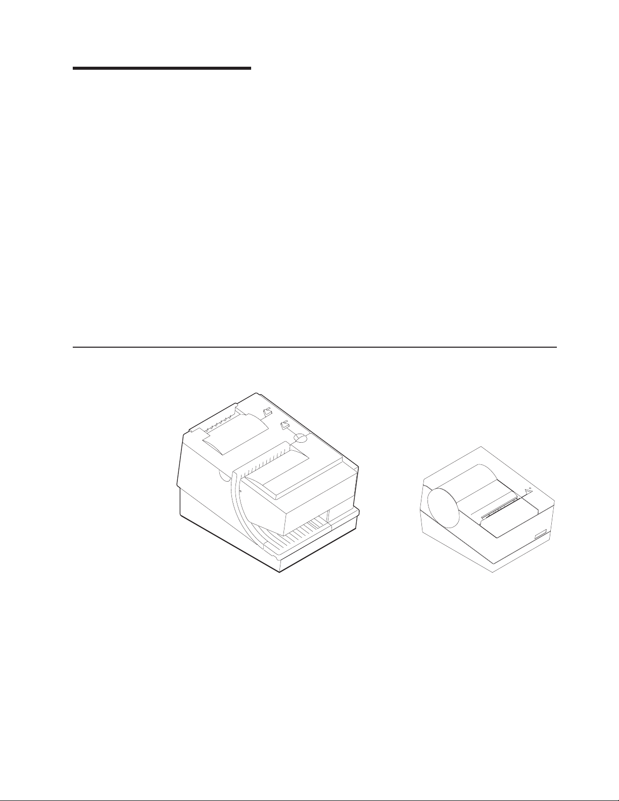
Figure 1. IBM SureMark Printers
The IBM SureMark printers are high-performance, high-function printers. The
SureMark is available in several models:
v Models TI5 and TG5 feature a thermal customer receipt station and an impact
v Models TF7 and TM7 are single-station thermal printers. They contain no
document insert station. The dual printheads enable quiet, fast printing at the
customer receipt station while providing the capability to print and frank checks
and to print multipart forms through the document insert station.
document insert station. These models cost less, weigh less, and have a smaller
footprint than the Models TI5 and TG5 printer. Models TF7 and TM7 have been
designed for wall mounting, if desired by the retailer.
© Copyright IBM Corp. 1999,2001 3
Page 28

updated March 18, 2002
All SureMark printers provide:
v Fast, quiet receipt printing
v Easy paper loading
v 2-MB flash memory for storing messages, logos, code pages, and double-byte
character sets
v Bar code generation
v Downloadable fonts and code pages
v Downloadable microcode
v Small footprint
v Support for RS-232 (EIA 232) and RS-485 (EIA 485) interfaces
The single-station SureMark printers, and also SureMark Models TI5 and TG5
printers that have been updated with the latest firmware, support the following in the
thermal station:
v Proportional fonts (SBCS only)
v Scalable fonts
v Color printing – black plus one accent on two-color thermal paper (thermal
station only)
v Upside-down printing
Additional features of some SureMark models include:
v Support for USB interface (models TI5, TG5, and TM7)
v Easy-to-load ribbon cartridge (Models TI5 and TG5)
v Epson emulation (models TF7 and TM7, SBCS only)
Description of Models
SureMark printers are available in the following models that can operate in either
single-byte character set (SBCS) mode or double-byte character set (DBCS) mode:
|
|
|
|
Models TI5 and TG5
Models TF7 and TM7
When any of these printers operates in DBCS mode, you can use one of the
following character sets (characters must be downloaded to the printer from the
Utility Diskette or using POSS for Windows):
v Japanese
v Korean
v Traditional Chinese
v Simplified Chinese
Standard models that supports receipt and document printing. Model TG5 is
equivalent to Model TI5 but with iron gray covers to match the IBM 4840
system units.
Smaller models that contain only a thermal customer receipt station.
Because there is no document insert station, these models do not support
document printing.
Models TF7 and TM7 have an audible alarm, a spill-resistant design, and
an optional wall mount.
For Food Service customers, the covers on Model TF7 match the IBM
SurePOS 500 Series systems. For Retail customers, the covers on Model
TM7 match the IBM 4694 systems if the RS-232/RS-485 interface is
ordered, and match the IBM SurePOS 700 Series systems if the USB
interface is ordered.
4 SureMark DBCS User’s Guide
Page 29

updated March 18, 2002
Note: IOR 24x7 is IBM onsite repair 24 hours times seven days per week. 9x5 is
nine hours per day for five days per week.
Features Used with the SureMark Printers
All models support the following features:
v Integration Panel
v 40-Character VFD Post Extension
v Distributed Printer Cable (RS-485)
v Integrated Cable (RS-485)
v Short RS-232 Communications Cable, 2 m (about 6.6 ft), P/N 86H2192
v Long RS-232 Communications Cable, 4 m (about 13.1 ft), P/N 86H2195
|
|
|
v Power Supply (RS-232 and USB), P/N 42H1176
v Power Cords (country-specific)
v RS-232/RS-485 Interface Card
Models TI5, TG5, and TM7 support the following features:
v USB Cable — Powered, 0.5 m (about 1.6 ft), P/N 01L1646
v USB Cable — Powered, 3.8 m (about 12.5 ft), P/N 01L647
v USB Cable — Standard, 5.0 m (about 16.4 ft), P/N 08L2014
v USB Interface Card
Because a cash drawer can attach directly to the SureMark, all models also support
the following features:
v Compact Cash Drawer - Vertical Till
v Compact Cash Drawer - Horizontal Till
v Full-size Cash Drawer - Adjustable Till
v Full-size Cash Drawer - Fixed Till Insert
v Short Cash Drawer Cable, P/N 72H3802
v Long Cash Drawer Cable, P/N 72H3803
Planning Information
Your Responsibilities
You are responsible for replenishing consumable supplies, including roll paper for
the thermal (customer receipt station) printer, and, depending on your model, forms
and ribbon cartridges for the impact (document insert) station. (See Appendix A,
“Consumable Supplies”.)
The customer must load the appropriate DBCS fonts in the printer.
If you plan to use RS-232 communications, you are responsible for ordering a 24 V
dc power supply with a power cord. You are also responsible for ordering the
RS-232 cable.
Note: If a 3-wire RS-232 cable is to be used, the printer must be set to XON/XOFF
mode. (See “RS-232 Communications Protocol Selection” on page 23.)
|
|
It is the customers responsibilities to update printer firmware as needed prior to
installing printers and as desired during the printer’s life.
Chapter 1. Introduction 5
Page 30

updated March 18, 2002
If you plan to use RS-485 communications, you are responsible for ordering the
RS-485 cable.
|
|
|
|
|
|
If you plan to use USB communications, you are responsible for ordering one of the
following:
v A powered USB cable, P/N 08L2014.
v A standard USB cable with a Type B connector for the printer, and a power brick.
The 3.8-m USB cable for a distributed configuration is P/N 01L1647 and the
0.5-m USB cable for an integrated configuration is P/N 01L1646.
SureMark printers have no physical journal station. You must use an
electronic journaling application instead. Electronic journaling eliminates the
need to store paper journal tapes and the time-consuming task of searching papers
should the need arise.
Limitations
SureMark printers have a safety feature that slows printing if excessive duty cycles
are used. This feature protects the printer hardware from potential damage and
should not be noticeable during normal operation.
Communication Interfaces
All SureMark printers can support the RS-232 and RS-485 interfaces. Models TI5,
TG5, and TM7 can also support the USB interface. For SureMark models that can
support the USB interface, you can upgrade installed printers from RS-232/RS-485
to USB by ordering a USB interface card.
RS-232 supports 9600 and 19 200 baud rates. RS-485 operates at a 187.5K baud
rate. USB supports data rates up to 12 Mbps.
6 SureMark DBCS User’s Guide
Page 31

updated March 18, 2002
Temperature and Humidity Limits
Shipping -40° to 60° C (-40° to 140° F) with 5% to 100% relative humidity
including condensation, but excluding rain
Storage 0to60° C (32 to 140° F)
Operating 0to40° C (32 to 104° F) with 8 to 80% relative humidity
To allow convection cooling, ventilation holes in the covers must not be blocked.
Physical Dimensions
Models TI5 and TG5
Width 190.5 mm (7.5 in.)
Depth 255 mm (10 in.)
Height Front: 140 mm (5.5 in.), Rear: 190 mm (7.5 in.)
Weight 4.4 kg (9.6 lb)
190 mm
(7.5 in.)
255 m
(10 in.)
m
Figure 2. SureMark Printer Dimensions – Models TI5 and TG5
200.5 m
(7.9 in.)
m
190.5 m
(7.5 in.)
m
Models TF7 and TM7
Width 145 mm (5.7 in.)
Depth 177 mm (7.0 in.)
Height Front: 95 mm (3.7 in.), Rear: 121 mm (4.8 in.)
Weight 1.4 kg (3.0 lb) without paper
1
4
0
m
(5
m
.5
in
.)
Chapter 1. Introduction 7
Page 32

121 m
(4.8 in.)
updated March 18, 2002
m
9
5
m
(3
m
.7
in
.)
177 m
(7.0 in.)
m
145 mm
(5.7 in.)
Figure 3. SureMark Printer Dimensions – Models TF7 and TM7
Power Requirements
The SureMark printers do not contain a power supply. When the printer is operating
in RS-232 mode, an external power supply must be attached to connector J2 of the
interface card of the printer. This connector is located under the printer and is
accessible without removing the printer covers. (See Figure 4 on page 12 for
thermal/impact SureMark printers, and Figure 5 on page 13 for single-station
SureMark printers.) Connector J2 has the following pin functions:
Pin Signal
1 +24Vdc
2 Not Connected
3 Ground
When the SureMark printer is operating in RS-485 mode, power is supplied to the
printer from the IBM POS system. The system supplies 5V, 24 V, or 38 V dc to the
printer.
|
|
|
|
When the SureMark printer has the USB feature installed and is using the powered
USB cable, 24V is supplied from the system unit.
When the SureMark printer has the USB feature installed and is using a 4-wire
cable with a Type B connector, you must use an external power brick (+24V dc).
Hardware Requirements
The SureMark printers work with the following systems:
v IBM 4694 systems (both SBCS and DBCS models)
v 4614 (RS-232 connection only with power supply)
v IBM 4695 systems (RS-232 connection only and with power supply)
8 SureMark DBCS User’s Guide
Page 33

updated March 18, 2002
v PC or other store controller with an RS-232 or USB port
|
v SurePOS 700 Series systems (USB connection only)
v SurePOS 500 Series systems (RS-232 connection only)
Software Requirements
Operating System Requirements
When using the RS-485 interface, attach SureMark printers to systems that are
running one of these operating systems:
v IBM PC DOS 2000 or later with POSS for DOS V1.60(c) or later
v Windows Version 3.1 or later with POSS for Windows V1.43 or later
v Windows NT Version 3.51 or later with POSS for Windows V1.43 or later
v Windows 95/98 with POSS for Windows V1.43 or later
v 4690 OS V2R4, when available
|
|
|
|
When using the USB interface, attach SureMark printers to systems that are
running one of these operating systems:
v Windows 98, 2nd Edition with POSS for Windows V2.00 or later
v Windows 2000 Professional with POSS for Windows V2.00 or later
When using the RS-232 or RS-485 interface, you can use OLE for Retail POS
(OPOS) V1.4.0 with the following operating systems, if POSS for Windows V1.43 or
later is first installed:
v Windows 95
v Windows NT 4.0
POSS drivers can be downloaded from the Retail Store Solutions Web site. See
“Resources on the Internet” on page 43 for more information.
If you use the RS-485 interface, you must use POSS or 4690 OS drivers. If you use
the RS-232 interface, use the commands described in Appendix C, “RS-232
Programming Information” on page 97.
Application Requirements
Many IBM retail applications run on the 4690 OS in single-byte mode. The
applications can be modified to run in double-byte mode with customer
engagement.
Customers must be at these application levels (or higher) when running the 4690
OS:
Application Name Product
IBM SUREPOS Application Client/Server Environment
for 4690 OS
IBM 4680 Chain Drug Sales Application 5669-212 9201
IBM 4680-4690 General Sales Application 5696-546 9701
IBM 4680-4690 Supermarket Application 5696-536 9701
Single-Byte Character Set (SBCS) Code Pages
These SBCS code pages are resident in the printer:
v Generic
v 437 (US)
v 858 (International)
Maintenance
Number
5745-C44 N/A
Level
Chapter 1. Introduction 9
Page 34

v 860 (Portuguese)
v 863 (Canadian French)
v 865 (Norwegian)
When you download a DBCS code page, the SBCS code page of the character set
is downloaded as user-defined code page 1. Additional code pages (three thermal
and one impact) can be downloaded, if desired, using the 4610 DBCS Installation
Utility Diskette. The diskette is available on the Web. See “Resources on the
Internet” on page 43 for more information.
Double-Byte Character Set (DBCS) Code Pages
The following DBCS code pages are available for downloading to Models TI5, TG5,
TF7, and TM7 of the SureMark printer:
v 932 (Japanese
v 949 (Korean)
v 950 (Traditional Chinese)
v 1381 (Simplified Chinese)
Use the 4610 DBCS Installation Utility Diskette to download the code pages. The
diskette is available on the Web. See “Resources on the Internet” on page 43 for
more information.
updated March 18, 2002
Bar Codes
When you download a DBCS code page, the SBCS code page of the character set
is downloaded as user-defined code page 1.
All character sets cannot be resident simultaneously.
SureMark printers can generate these bar codes:
v UPC-A
v UPC-E
v JAN13 (EAN-13)
v JAN8 (EAN-8)
v Code 39
v ITF
v Codabar
v Code 128C
v Codes 128A, 128B, and 128C (requires latest firmware for Models TI5 and TG5)
v Code 93
v PDF 417
10 SureMark DBCS User’s Guide
Page 35

updated March 18, 2002
Chapter 2. Installation Instructions
Unpacking the Printer ......................11
Installing the SureMark Printers ...................12
Installing for RS-232/RS-485 Communication .............12
||
||
||
Installing for USB Communication .................15
Using the Wall Mounting Feature ..................18
Installing the Fillers .......................19
Installing Fillers for RS-232/RS-485 Printers .............19
Installing Fillers for USB Printers .................21
RS-232 Communication Mode Selections ...............23
Baud Rate Selection ......................23
RS-232 Communications Protocol Selection .............23
DTR/DSR Control ......................23
XON/XOFF Control .....................24
USB Communication Mode ....................25
USB Selection .........................25
Before installing a SureMark printer, be sure to read “Electronic Emission Notices”
on page 173.
DANGER
To avoid a shock hazard, do not connect or disconnect any cables
or perform installation, maintenance, or reconfiguration of this
product during an electrical storm.
DANGER
To avoid shock hazard:
The power cord must be connected to a properly wired and
earthed receptacle.
Any equipment to which this product will be attached must also
be connected to properly wired receptacles.
Note: For translations of these safety notices, see IBM Safety Information – Read
This First, GA27–4004.
Unpacking the Printer
Note: Save all packing material and shipping containers.
1. Remove the SureMark printer from the shipping container and place it on a flat
surface.
2. Open any shipping containers of additional options and accessories to install
with the SureMark printer.
3. Carefully remove any remaining packing material and packing tape.
© Copyright IBM Corp. 1999,2001 11
Page 36

Installing the SureMark Printers
Installing for RS-232/RS-485 Communication
1. Power the system off and disconnect the RS-232 power supply.
2. Locate the rear cable connectors.
3. If you are using the RS-232 communication port:
a. Check the settings on the RS-232 mode switch, which is near the rear
cable connections. (See Figure 4.) See “RS-232 Communication Mode
Selections” on page 23 for information on switch settings.
Note: If the RS-232 communication cable has only 3 wires or if the system
output is 3 pins (2 signals and a ground), you must use XON/XOFF
mode.
b. Connect the power supply to the printer.
4. Connect the RS-485 or RS-232 communication cable to the correct port.
updated March 18, 2002
1
OFF
2
RS 232
Mode
Switch
Figure 4. Cable Connectors and RS-232 Settings Switch for Thermal/Impact SureMark Printers. (View is from the
bottom rear of the printer.)
Cash
Drawer
Por t
Power Supply
Por t (RS 232
Only)
RS 232
Por t
RS 485 Port
12 SureMark DBCS User’s Guide
Page 37

updated March 18, 2002
Power supply port (RS-232 only)
RS-232 port
RS-485 port
Cash drawer connector
Figure 5. Cable Connectors for Single-Station SureMark Printers. (View is from the bottom rear of the printer)
OFF
4
3
2
1
RS-232 mode switches
Cash drawer connector
Figure 6. RS-232 Mode Switches for Single-Station SureMark Printers. (View is from the bottom rear of the printer)
5. For single-station printers, route any power cord and cables as shown in
Figure 7 on page 14.
Chapter 2. Installation Instructions 13
Page 38

updated March 18, 2002
Cash drawer cable
Power cord
RS-232 cable
Figure 7. RS-232 and RS-485 Cable Routing for Single-Station SureMark Printers
Cash drawer cable
RS-485 cable
6. Connect any other signal cables for I/O devices to the correct ports.
7. Check that all signal cables are installed and seated in the correct ports.
8. If you are installing the printer on an integrated unit:
a. Pull out the locking lever at the left side of the system unit. (wide systems
only)
b. For single-station printers, place the printer in the square-shaped filler
panel.
c. Route the keyboard cable to the side of the tab as shown in Figure 12 on
page 20.
d. Route all cables attached to the printer through the center opening of the
system unit and place the printer (with its filler panel, if it is a single-station
printer) on the system unit.
e. If you have fillers to install, go to “Installing the Fillers” on page 19.
f. Lift the system unit rear cover and attach any cables from the printer to the
system unit. (If this is a RS-232-attached printer, reattach the brick power
cord if you had to detach it to route it through the center opening.)
9. Power on the printer by either:
v Connecting the brick power supply cable to a properly wired and grounded
power source and powering it on
v Powering on the POS system unit for an RS-485-attached printer.
Note: Both voltage sources should not be connected to the printer at the
same time, even if one of the sources is powered off. Potential
system damage could occur under these conditions.
10. For single-station SureMark printers, turn on the power on/off switch on the
printer.
14 SureMark DBCS User’s Guide
Page 39

updated March 18, 2002
11. For thermal/impact printers, locate the ribbon cartridge and install it in the
printer. (See “Ribbon Loading” on page 49.) Be sure that the ribbon is routed
through the printhead correctly.
12. Load the paper roll into the printer. See “Paper Loading” on page 51 for
thermal/impact SureMark printers or “Paper Loading” on page 63 for
single-station SureMark printers.
13. Installation is now complete. Go to Chapter 5, “Testing and Problem Analysis –
Models TI5 and TG5” on page 55 for thermal/impact printers or Chapter 7,
“Testing and Problem Analysis – Models TF7 and TM7” on page 67 for
single-station printers and run the offline tests.
Installing for USB Communication
|
|
|
1. Disconnect the power brick from the printer, if one is connected.
2. Locate the rear cable connectors.
||
Cash
Drawer
Por t
Figure 8. USB Ports for Thermal/Impact SureMark Printers (View is from the bottom rear of the printer)
Power
Supply
Por t
Powered
USB Port
Standard
USB Port
Chapter 2. Installation Instructions 15
Page 40

updated March 18, 2002
|
Power supply port
Powered USB port
Standard USB port
Cash drawer connector
|
|
|
|
|
|
|
|
Cash drawer cable
Standard USB cable
Power cord
Figure 9. USB Ports for Single-Station SureMark Printers. (View is from the bottom rear of
the printer)
3. For single-station printers, route any power cord and cables as shown in
Figure 10.
Cash drawer cable
Powered USB cable
|
Figure 10. USB Cable Routing for Single-Station SureMark Printers
|
|
|
|
4. Connect the USB communication cable to the correct port.
5. Connect any other signal cables for I/O devices to the correct ports.
16 SureMark DBCS User’s Guide
Page 41

updated March 18, 2002
|
|
|
|
|
|
|
|
|
|
|
|
|
|
|
|
|
|
|
|
|
|
|
|
|
|
|
|
|
|
6. Check that all signal cables are installed and seated in the correct ports.
7. If you are installing the printer on an integrated SurePOS 700 Series system:
a. For single-station printers, place the printer in the square-shaped filler
panel.
b. Route all cables attached to the printer through a rear opening of the
system unit and place the printer (with its filler panel, if it is a single-station
printer) on the system unit.
c. Make the side of the printer overlap the tab on the side of the system unit.
(wide systems only)
d. If you have additional fillers to install, go to “Installing the Fillers” on
page 19.
e. If a fence or I/O tray is installed, lift the system unit rear cover and attach
any cables from the printer to the system unit. (If a power brick was
disconnected at the beginning of the installation or is needed because a
standard USB cable is being used, attach the power brick.)
8. If you are using a power brick, power on the printer by connecting the power
brick supply cable to a properly wired and grounded power source and
powering it on.
9. For single-station SureMark printers, turn on the power on/off switch on the
printer.
10. For thermal/impact printers, locate the ribbon cartridge and install it in the
printer. (See “Ribbon Loading” on page 49.) Be sure that the ribbon is routed
through the printhead correctly.
11. Load the paper roll into the printer. See “Paper Loading” on page 51 for
thermal/impact SureMark printers or “Paper Loading” on page 63 for
single-station SureMark printers.
12. Installation is now complete. Go to Chapter 5, “Testing and Problem Analysis –
Models TI5 and TG5” on page 55 for thermal/impact printers or Chapter 7,
“Testing and Problem Analysis – Models TF7 and TM7” on page 67 for
single-station printers and run the offline tests.
Chapter 2. Installation Instructions 17
Page 42

Using the Wall Mounting Feature
Because of their light weight and small footprint, the single-station SureMark
printers can be mounted on a wall. This is a useful feature when counter space is
limited.
To use the printer with the wall mounting feature:
1. Position the mounting bracket on a wall that has no dangerous objects, such as
electrical wires or pipes, hidden beneath the wall surface.
Note: Position the bracket so that the installed printer will not extend more than
10 cm (4 in.) into a walk, hall, corridor, passageway or aisle.
2. Attach the bracket securely to the wall with four 6-mm (0.25-in.) screws. The
screws are not provided. You should use fasteners that are suitable for the type
of wall construction, such that the bracket is securely attached to the wall. For
walls that are constructed of gypsum wallboard on wood or metal studs, use
four good-quality medium-capacity or high-capacity hollow-wall anchors.
3. Route the communication cable up the wall surface or through the bracket.
4. Connect the cables to the printer.
5. Place the SureMark printer on the two bracket posts. Slide the printer down until
a click sounds.
updated March 18, 2002
Wall bracket
Mounting posts
Screws (not provided)
SureMark with top cover open
Figure 11. Mounting a Single-Station SureMark on a Wall
18 SureMark DBCS User’s Guide
Page 43

updated March 18, 2002
Installing the Fillers
Installing Fillers for RS-232/RS-485 Printers
Notes:
1. On an integrated unit, pull out on the locking lever at the left side of system unit.
2. Ensure that the side of each filler overlaps the tab on the side of the system
unit.
To install fillers:
1. Power off the system and disconnect the RS-232 power supply (if connected).
See Figure 4 on page 12.
2. If you have a video display on an integrated system:
a. Move the display on its arm to the side and remove any tape holding the
alignment ring.
b. Remove the knockout section of the display filler.
c. Align the display filler with the alignment ring and slide the filler onto the
ring. Press the display filler into place. See Figure 12 on page 20.
3. If you do not have a video display, place the display filler on the system unit. Do
not remove the knockout section. See Figure 12 on page 20.
4. If you have a short keyboard, place the keyboard filler beside the keyboard. See
Figure 12 on page 20.
5. Place the printer filler beside the display filler. Make sure you route the printer
cable to the side, as shown in Figure 12 on page 20.
Chapter 2. Installation Instructions 19
Page 44

updated March 18, 2002
Knockout
Section
Display Filler
Printer Filler
Alignment
Ring
Display Filler
Keyboard Filler
Ta b
Locking Lever Cable
Figure 12. Installing the Fillers for RS-232/RS-485 Systems
20 SureMark DBCS User’s Guide
Page 45

updated March 18, 2002
Installing Fillers for USB Printers
|
|
|
|
|
|
|
|
|
|
1. Disconnect the power brick from the printer, if one is connected.
2. Place the display filler appropriate for the video display on the system unit. Do
not remove the knockout section unless you have an integrated video mount.
See Figure 13 on page 22.
3. If you have a short keyboard, place the keyboard filler beside the keyboard. See
Figure 13 on page 22.
4. Place the printer filler beside the display filler. Make sure you route the
keyboard cable to the side, as shown in Figure 13 on page 22.
Chapter 2. Installation Instructions 21
Page 46

updated March 18, 2002
Knockout
Section
Display Filler
Printer Filler
Alignment
Ring
Display Filler
Keyboard Filler
Ta b
Cable
Figure 13. Installing the Fillers for USB Systems. (SurePOS 700 Series system is shown as an example.)
22 SureMark DBCS User’s Guide
Page 47

updated March 18, 2002
RS-232 Communication Mode Selections
Switch settings described in this section apply only when the printer is connected to
the system with the RS-232 cable. The switch is accessible without removing the
printer covers. (See Figure 4 on page 12 to see how to access the switch.)
Baud Rate Selection
SureMark printers support two RS-232 baud rates, 9600 and 19 200. The baud rate
is selected using switch 1 on the RS-232 settings switch. Set the switch as follows:
Switch 1 OFF 9600 baud
Switch 1 ON 19 200 baud
The printer normally ships with switch 1 in the OFF position, which selects the 9600
baud rate.
RS-232 Communications Protocol Selection
SureMark printers support RS-232 protocol using either DTR/DSR or XON/XOFF to
control data transmission. XON/XOFF mode uses system and printer software to
control the flow of data.
Use switch 2 on the RS-232 settings switch to select the mode. Switch settings are:
Switch 2 OFF DTR/DSR control
Switch 2 ON XON/XOFF control (must use with a 3-wire interface)
The printer normally ships with switch 2 in the OFF position, which selects
DTR/DSR control.
DTR/DSR Control
DSR Definition: DSR is an output from the printer. It indicates when the printer is
ready to receive data.
DTR Definition: DTR is an input to the printer. It indicates to the printer that the
system is ready to receive data.
DSR Operation: A DSR signal becomes inactive when the printer is not ready to
receive data (for example, at power-on reset or when its buffer is full).
Chapter 2. Installation Instructions 23
Page 48

updated March 18, 2002
DTR Operation: A DTR signal becomes inactive when the system is not ready to
receive data (for example, at power-on reset or when its buffer is full).
XON/XOFF Control
XON Definition: = DC1 (X'11')
XOFF Definition: = DC3 (X'13')
During XON/XOFF control, the printer transmits an XON every 3 seconds after a
power on reset (POR) completes to indicate the printer is ready to receive data.
When the first message is received, the printer stops transmitting the XON signal.
The printer transmits an XOFF when the RS-232 input buffer is 80% full after which
it transmits one XON when the buffer is 20% full.
XON/XOFF Transparent Mode Operation
This is the default mode. See “Message from the Printer” on page 160 for the
format of printer to system messages, which include a byte count, status bytes, and
optional extended status bytes or user data.
XON and XOFF signals are always transmitted independently and are not inside
any part of the message, including the byte count, status bytes, or user data. When
a message includes optional user data, the byte count (bytes 1 and 2) can include
X'10', X'11', or X'13'. When X'10', X'11', or X'13' occur in transparent XON/XOFF
mode, the byte count is bit-exclusive-OR’ed with X'21' and is prefixed by the DLE
(X'10') character to become:
Value in Message Becomes
X'10' X'1031'
X'11' X'1030'
X'13' X'1032'
User data with X'10', X'11', or X'13' is also treated this way in transparent
XON/XOFF mode. The byte count is not incremented for such extra characters.
Determining XON/XOFF Control
You can determine whether XON/XOFF control is being used by sending the
extended address command and checking the feature byte, bit 3. If this bit is set,
the printer is in XON/XOFF mode. (See “Extended Address Command – Request
Printer ID” on page 107.
Disabling XON/XOFF Transparent Mode
You can disable transparent XON/XOFF mode as described in “Real-Time
Requests” on page 156. When disabled, X'10', X'11', or X'13' can occur within
messages. However, because such values are actual count bytes or data bytes and
are not XON or XOFF characters (DLE, XON, and XOFF characters do not occur
within messages), no transform takes place. The values are not bit-exclusive-OR’ed
with X'21' because no transform occurs for such values within messages as it does
during transparent XON/XOFF mode. DLE, XON, or XOFF occur only before or
after a message.
24 SureMark DBCS User’s Guide
Page 49

updated March 18, 2002
USB Communication Mode
|
|
|
|
|
USB Selection
No switches or special commands are required for USB communication. With the
USB interface card and cables in place, the system automatically detects the printer
when it is attached and performs any necessary setup. The printer operates at data
rates up to 12 Mbps.
Universal serial bus (USB) is an industry standard communication interface. It is
used to attach devices, such as printers, displays, and keyboards, to personal
computers or IBM POS systems that have USB ports. The standard USB port (with
a power brick) is used to attach the SureMark to personal computers. The powered
USB port is used to attach the SureMark to IBM POS systems. See Figure 8 on
page 15 for the thermal/impact SureMark printers and Figure 9 on page 16 for the
single-station SureMark printers.
Chapter 2. Installation Instructions 25
Page 50

updated March 18, 2002
26 SureMark DBCS User’s Guide
Page 51

updated March 18, 2002
Chapter 3. SureMark Installation, Service, and Utility Software
Software Adjustments (Models TI5 and TG5 Only) ............27
Using the 4690 Operating System .................27
||
Using IBM Point-of-Sale Device Diagnostics .............28
Using Reference/Service Diskettes (RS-485 or RS-232 Only) .......28
4610 DBCS Installation Utility Diskette ................31
DBCS Code Page Download ....................31
4610 DBCS Installation Utility Diskette Code Page Download.......31
DBCS Code Page Download – POSS for Windows (RS-485 and USB only) 33
DBCS User-Defined Character Download ...............35
Firmware Update ........................36
4610 DBCS Installation Utility Diskette for Updating SureMark Firmware. . . 36
Using POSS For Windows for Updating SureMark Firmware (RS-485 and
USB Only).........................37
Using 4690 OS 4610 Utility to Update SureMark Firmware ........38
Updating 4610 Firmware Using RS-232 Attachment Cable ........38
Limitation on Updating Firmware .................39
Emulating the IBM Model 3 or Model 4 Printers .............39
Enabling Emulation Using 4610 DBCS Installation Utility Diskette .....39
Enabling Emulation Using 4690 On-Line Terminal Diagnostics ......40
Limitations for Emulation ....................40
Printing Saved Data ......................41
Printing Buffer Data – Thermal/Impact SureMark Models TI5 and TG5 41
Printing Buffer Data – Single-Station SureMark Printers ........41
Emulating an Epson Single-Station Printer (Single-Station SureMark Only) . . . 41
Enabling Epson Emulation....................42
Limitations for Epson Emulation..................42
Changing the Printer Mode between DBCS and SBCS ..........42
Proportional Font Conversion Utility .................43
Resources on the Internet .....................43
This chapter describes how to make software adjustments using the 4690 OS, IBM
POS Device Diagnostics (POSS for Windows, RS-485 and USB only), or diskettes
and other resources that are available from the Retail Store Solutions Web site.
See “Resources on the Internet” on page 43 for more information.
Software Adjustments (Models TI5 and TG5 Only)
Depending on your operating system and whether the printer is operating in SBCS
or DBCS mode, you can use the following to make software adjustments to a
SureMark printer:
v 4690 Operating System
v IBM POS Device Diagnostics
v Reference/service diskettes
Using the 4690 Operating System
Note: This procedure is applicable only in SBCS mode, when DBCS is supported
by customer engagement, or with 4690 OS V2R4, when it is available.
1. Start Utility Mode by pressing S1, typing 95, and then pressing S2.
2. When “enter request” is displayed, enter the keying sequence from the table for
the procedure you want to do.
© Copyright IBM Corp. 1999,2001 27
Page 52

3. Press S2 to advance through the various parts of the printer adjustment steps.
4. Type 99and then press S2 to exit.
Table 2. Adjustment Procedures Using 4690 Operating System
Procedure Keying Sequence
Print Current Adjustment Values - see Figure 14 on page 30. 7, 2, 1, S2
Character Alignment Procedure - see Figure 14 on page 30. 7, 2, 2, S2
DI Front Load Print Line Adjustment - see Figure 14 on
page 30.
Backlash Adjustment (Landscape) 7, 2, 5, S2
Engineering Use Only 7, 2, 7, S2
Hardware Setup Option 7, 2, 8, S2
Update Printer Firmware 7, 2, 9, S2
Using IBM Point-of-Sale Device Diagnostics
|
|
|
|
|
|
|
This utility is for RS-485 and USB only.
1. Start the IBM Point-of-Sale Device Diagnostics application from the Windows
Start menu.
2. Click 4610 Printer.
3. Click Device Utility.
4. Select the appropriate tab for the desired adjustment:
updated March 18, 2002
7, 2, 3, S2
|
|
||
||
||
||
||
||
||
||
||
||
||
Table 3. Adjustment Procedures Using the Point-of-Sale Device Diagnostics
Procedure Tab
Character Alignment Adjustments
DI Front Load Adjustment Adjustments
Backlash Adjustment (Landscape) Adjustments
Engineering Use Only Read MCT
Firmware Update Firmware Update
Reset Thermal Print Head Statistics Reset Stats
Reset CR Motor Statistics Reset Stats
Reset Impact Print Head Statistics Reset Stats
Reset DI Motor Statistics Reset Stats
Reset Transport Motor Statistics Reset Stats
Using Reference/Service Diskettes (RS-485 or RS-232 Only)
1. Load the reference/service diskette. See the hardware service manual for your
system for reference/service diskette procedures.
2. Select Test Menu.
3. Select Run POS Device Tests for an RS-485 connection. Select RS232 4610
Printer Test for an RS-232 connection.
4. If another system is attached, select the system whose printer you want to
adjust. This is unnecessary when there is no other system attached.
5. Select Printer Utilities.
6. Select the adjustment you want to make from the menu.
28 SureMark DBCS User’s Guide
Page 53

updated March 18, 2002
v Print current adjustment values - see Figure 14 on page 30.
v Character alignment procedure - see Figure 14 on page 30.
v DI front load print line adjustment - see Figure 14 on page 30.
v Document landscape adjustment - see Figure 14 on page 30.
v Engineering use only
v Change 4610 Model Configuration
v Reset printer statistics
Note: Because the first four adjustments affect only the document insert
station, they are not displayed as selectable options if the printer is a
single-station SureMark.
7. Follow the instructions that are printed on the printer or displayed on the screen.
8. Press S1 (Esc on the Enhanced A/N Keyboard) to return to the previous menu.
Chapter 3. SureMark Installation, Service, and Utility Software 29
Page 54

CURRENT ADJUSTMENT VALUES
H 5 = Character alignment
TL5 = Top line front insert
BL3 = Bottom line top insert
CHARACTER ALIGNMENT PROCEDURE
updated March 18, 2002
TL1
TL2
TL3
TL4
TL5
TL6
TL7
TL8
TL9
Measure from the top edge of this
paper to the top of each print line.
Press the key (1-9) that corresponds
to the print line that is closest to 5MM.
Press the key (1-9) that corresponds
to the pair of H's that appear to be
most aligned
5 = selected line
Figure 14. Adjustment and Alignment Printouts
30 SureMark DBCS User’s Guide
Page 55

updated March 18, 2002
4610 DBCS Installation Utility Diskette
This utility is for both RS-232 and RS-485 operation. It includes:
v The latest level of firmware for the printer
v A README file that describes how to use the utility program.
v A utility program that performs the following functions:
– Update printer firmware
– Configure the printer model
– Create, edit, and download SBCS user-defined character font, logo image,
and messages
– Edit and download DBCS code pages and DBCS user-defined character font
– Convert fonts and logo files from impact to thermal
v Sample files for the utility program:
– An SBCS user-defined character file
– A message file
– A logo file
v Utility program to enable/disable Model 4 Printer emulation (SBCS mode only)
v Utility program to change the printer mode between DBCS and SBCS
DBCS Code Page Download
SureMark models TI5, TG5, TF7, and TM7 can receive a DBCS code page from an
attached host system connected by an RS-485 cable (cable 7), an RS-232 cable, or
a USB cable.
The following mediums can be used to download a DBCS code page:
v 4610 DBCS Installation Utility Diskette code page download (RS-485 or RS-232
connection)
v POSS for Windows DBCS code page download (RS-485 or USB connection)
v 4690 OS V2R4 font download, when available
After downloading the latest level software from the Retail Store Solutions Web site
(see “Resources on the Internet” on page 43), use the appropriate procedure that
follows to download a DBCS code page.
4610 DBCS Installation Utility Diskette Code Page Download
Use the 4610 DBCS Installation Utility Diskette to download a DBCS code page to
a SureMark that is connected to a system unit by either an RS-232 or RS-485
cable.
To download a diskette font, perform the following steps:
1. Download the fonts diskette from the Retail Store Solutions Web site (see
“Resources on the Internet” on page 43).
2. Download the latest level of the 4610 DBCS Installation Utility Diskette from
the Retail Store Solutions Web site (see “Resources on the Internet” on
page 43). Place the file that you download, which is 4610dbcs.exe, in a
temporary directory. Run 4610dbcs.exe in a DOS window to create the
diskette. If you are using Windows NT, you might need to use FORCEDOS.
3. Insert the 4610 DBCS Installation Utility Diskette in drive A.
4. Power on the system unit to which the SureMark is connected.
5. Select Run Printer Utility for the RS-232 or RS-485 connection.
6. Follow the displayed instructions to complete the font download.
Chapter 3. SureMark Installation, Service, and Utility Software 31
Page 56

updated March 18, 2002
a. Press Enter (OK) at the logo screen.
b. Select the connection type (RS-485 or RS-232).
For the RS-232 connection, also select the following:
v Communications port (COM1, COM2, COM3, COM4)
v Baud rate (9600 or 19 200)
v Control flow (DTR/DSR or XON/XOFF)
v IRQ test
Refer to the communication mode selection switches located at the bottom
rear of the SureMark printer when making the above selection.
c. Press Enter (OK).
d. Select the printer model, then select Enter (OK).
e. Select F10 (Menu).
f. Select O (Operations).
g. Select F (Download Fonts).
h. If you want to selectively download code pages, go to Step 6j. Otherwise,
select one of the font sets from the font set menu, then select D
(Download). Use this option with POSS for Windows, OPOS, or JavaPOS
drivers.
The following DBCS font files are downloaded to the printer when you
select Yes (you can change the list of files in a:\utility\fontset.dat before
selecting Yes):
v DBCS for thermal printhead
v DBCS for impact printhead
v SBCS for user-defined thermal code page 1
v SBCS for user-defined impact code page 1
v DBCS user-defined character for thermal printhead
v DBCS user-defined character for impact printhead
i. When prompted, insert the appropriate DBCS Font Diskette in drive A (see
“Resources on the Internet” on page 43 for information about downloading
the diskette), then select OK.
Go to Step 7.
j. Select S (Selective Download).
k. Select E (Erase EPROM).
l. Select the code set (SBCS or DBCS), code page, station (Thermal or
m. Select B (Browse) and specify the font file, if required.
n. Select D (Download).
o. Select Yes. When prompted, insert the appropriate DBCS Font Diskette in
p. Go to Step 7.
7. After the font download has completed,
32 SureMark DBCS User’s Guide
Note: If you are using the 4610 DBCS Installation Utility Diskette with a
printer that will be used with POSS for Windows, OPOS, or
JavaPOS drivers, then do not use the selective download. If you
use the selective download with those drivers, the drivers will not
recognize what DBCS code page has been downloaded.
Impact), and characters (Normal or User-Defined).
drive A (see “Resources on the Internet” on page 43 for information about
downloading the diskette), then select OK.
Page 57

updated March 18, 2002
a. Press Done for confirmation if Download (Step 6h on page 32) was used.
Press OK for confirmation if Selective Download (Step 6j on page 32) was
used.
b. Press C (Close) to close the dialog.
c. Press Alt-X (Exit) to exit the menu.
d. Press Enter to exit the utility.
8. When prompted, reinsert the 4610 DBCS Installation Utility Diskette, then
press Enter.
9. Remove the diskette from drive A.
10. Press Ctrl-Alt-Delete to reboot the system.
DBCS Code Page Download – POSS for Windows (RS-485 and USB only)
DBCS fonts must be manually loaded into the SureMark printer. The process
requires files that are downloaded from the IBM Retail Store Solutions Web site,
including the 4610CVNT.EXE and AIPFNT46.EXE programs. For details, refer to the
POSS Programming Reference and User’s Guide.
Note: This utility requires POS Suite V1.0.0 or greater. POS Suite includes POSS
for Windows.
1. Download the latest DBCS font files from the IBM Retail Store Solutions Web
site to the same directory in which POSS for Windows is installed, which is
usually the C:\POS\BIN directory. To access the files on the Web:
a. Go to the IBM Retail Store Solutions Web site at
http://www.ibm.com/solutions/retail/store
b. Select Support at the left edge of the main page.
c. Under IBM SurePOS Systems and Peripherals, select IBM SureMark
Printer.
d. Select the link to the Model TI5 and TG5 support page.
e. Select the font files that you want to download.
The files for each DBCS code page are shown in Table 4.
Table 4. Font Files for DBCS Code Pages
Code Page File Name Codeset Station Where to Download
932
Japan
Gothic Style
932
Japan
Mincho Style
jpngh16.fnt
jpngz16.fnt
jpngh24.fnt
jpngz24.fnt
judcz16.fnt
judcz24.fnt
jpnmh16.fnt
jpnmz16.fnt
jpnmh24.fnt
jpnmz24.fnt
judcz16.fnt
judcz24.fnt
SBCS
DBCS
SBCS
DBCS
DBCS
DBCS
SBCS
DBCS
SBCS
DBCS
DBCS
DBCS
Impact
Impact
Thermal
Thermal
Thermal
Thermal
Impact
Impact
Thermal
Thermal
Thermal
Thermal
Chapter 3. SureMark Installation, Service, and Utility Software 33
Impact code page 1
Impact DBCS
Thermal code page 1
Thermal DBCS
Impact DBCS UDC
Thermal DBCS UDC
Impact code page 1
Impact DBCS
Thermal code page 1
Thermal DBCS
Impact DBCS UDC
Thermal DBCS UDC
Page 58

updated March 18, 2002
Table 4. Font Files for DBCS Code Pages (continued)
Code Page File Name Codeset Station Where to Download
949
Korea
1381
Chinese
PRC
(Simplified)
950
Chinese
Taiwan
(Traditional)
950
Chinese
Taiwan
(Traditional)
kormh16.fnt
kormz16.fnt
kormh24.fnt
kormz24.fnt
kudcz16.fnt
kudcz24.fnt
prcmh16.fnt
prcmz16.fnt
prcmh24.fnt
prcmz24.fnt
pudcz16.fnt
pudcz24.fnt
rocmh16.fnt (Note 1)
rocmz16.fnt
rocmh24.fnt
rocmz24a.fnt (Note 2)
rocmz24b.fnt (Note 2)
rudcz16.fnt
rudcz24.fnt
rocmh16b.fnt (Note 1)
rocmz16.fnt
rocmh24.fnt
rocmz24a.fnt (Note 2)
rocmz24b.fnt (Note 2)
rudcz16.fnt
rudcz24.fnt
SBCS
DBCS
SBCS
DBCS
DBCS
DBCS
SBCS
DBCS
SBCS
DBCS
DBCS
DBCS
SBCS
DBCS
SBCS
DBCS
DBCS
DBCS
DBCS
SBCS
DBCS
SBCS
DBCS
DBCS
DBCS
DBCS
Impact
Impact
Thermal
Thermal
Thermal
Thermal
Impact
Impact
Thermal
Thermal
Thermal
Thermal
Impact
Impact
Thermal
Thermal
Thermal
Thermal
Thermal
Impact
Impact
Thermal
Thermal
Thermal
Thermal
Thermal
Impact code page 1
Impact DBCS
Thermal code page 1
Thermal DBCS
Impact DBCS UDC
Thermal DBCS UDC
Impact code page 1
Impact DBCS
Thermal code page 1
Thermal DBCS
Impact DBCS UDC
Thermal DBCS UDC
Impact code page 1
Impact DBCS
Thermal code page 1
Thermal DBCS
Thermal DBCS
Impact DBCS UDC
Thermal DBCS UDC
Impact code page 1
Impact DBCS
Thermal code page 1
Thermal DBCS
Thermal DBCS
Impact DBCS UDC
Thermal DBCS UDC
Notes:
a. The file rocmh16b.fnt contains bold fonts and the file rocmh16.fnt contains
normal fonts.
b. The file rocmz24a.fnt contains the BIG-5 code set and the IBM Selected
non-Chinese character set (first byte A1-F9 and second byte 40-7E, A1-FE).
The file rocmz24b.fnt contains the IBM Selected non-Chinese/Chinese
character set (first byte F2-F9 and second byte 81-A0).
2. Download the 4610CVNT.EXE program and the configuration files that it uses.
To access the program and its files:
a. Go to the IBM Retail Store Solutions Web site at
http://www.ibm.com/solutions/retail/store
b. Select Support at the left edge of the main page.
c. Under SurePOS Peripherals, select IBM SureMark Printer.
d. Select the link to the Model TI5 and TG5 support page.
e. Select Font Utility Package to download the zipped file that contains the
program and the configuration files.
f. Unzip the program and the configuration files into the same directory that
contains the font files that you previously downloaded.
3. Enter the 4610CVNT config_file command to create the font file that will be
loaded into the printer. config_file is the name of the appropriate configuration
file from the following list:
JPNGS932.CFG
Code page 932, Japan, Gothic style
34 SureMark DBCS User’s Guide
Page 59

updated March 18, 2002
JPNMS932.CFG
Code page 932, Japan, Mincho style
KORMS949.CFG
Code page 949, Korea
CHNM1381.CFG
Code page 1381, Chinese – PRC
CHNM950N.CFG
Code page 950, Chinese – Taiwan, normal impact SBCS
CHNM950B.CFG
Code page 950, Chinese – Taiwan, bold impact SBCS
4. The font file is created. The file name is XXX.FON, where XXX is the same as
the configuration file. For example, when you run the 4610CVNT program with
JPNMS932.CFG, the font file is JPNMS932.FON.
5. Enter the following command to download the font set to the printer
(AIPFNT46.EXE should be in the same directory in which POSS for Windows is
installed, which is usually C:\POS:\BIN)
AIPFNT46 -s slot_number -p port_number -f font_file
where:
slot_number
The SureMark slot number. This is usually 1.
port_number
The SureMark port number. This is usually 17.
font_file
The name of the file created by the 4610CVNT.EXE program.
6. Wait a while. The SureMark font download takes several minutes.
DBCS User-Defined Character Download
To create a new character, use the 4610 DBCS Installation Utility Diskette with a
SureMark that is connected to a system unit by either an RS-232 or RS-485 cable.
The system unit must have a diskette drive, a PC keyboard, and a display.
To download a user-defined character:
1. Download the latest level of the 4610 DBCS Installation Utility Diskette from the
Retail Store Solutions Web site (see “Resources on the Internet” on page 43).
2. Insert the 4610 DBCS Installation Utility Diskette in drive A.
3. Power on the system unit to which the SureMark is connected.
4. Select Run Printer Utility for the RS-232 or RS-485 connection.
5. Follow the displayed instructions to complete the font download.
a. Press Enter (OK) at the logo screen.
b. Select the connection type (RS-485 or RS-232).
For the RS-232 connection, also select the following:
v Communications port (COM1, COM2, COM3, COM4)
v Baud rate (9600 or 19 200)
v Control flow (DTR/DSR or XON/XOFF)
Refer to the communication mode selection switches located at the bottom
rear of the SureMark printer when making the above selection.
Chapter 3. SureMark Installation, Service, and Utility Software 35
Page 60

updated March 18, 2002
c. Press Enter (OK).
d. Select F10 (Menu).
e. Select E (Edit).
f. Select D (Edit Font File).
g. Insert the font diskette, which includes the DBCS UDC font files. The DBCS
UDC font file names for each code page and type of station are shown in
Table 5.
Table 5. UDC Font File Names for DBCS Code Pages
Code Page File Name Station
932 (Japan) judcz16.fnt
judcz24.fnt
949 (Korea) kudcz16.fnt
kudcz24.fnt
1381 (PRC) pudcz16.fnt
pudcz24.fnt
950 (Taiwan) rudcz16.fnt
rudcz24.fnt
Impact
Thermal
Impact
Thermal
Impact
Thermal
Impact
Thermal
h. Select a font file and press Enter (OK).
i. Edit the font and save it.
6. To download the file, see “DBCS Code Page Download” on page 31.
Firmware Update
|
|
The SureMark printer has the capability to receive firmware updates from the host
system unit to which it is attached for RS-485, RS-232, or USB connections.
The following mediums can be used to update the SureMark firmware:
v 4610 DBCS Installation Utility Diskette Firmware Update
v POSS for Windows 4610 Printer Firmware Update Program
v 4690 OS 4610 Utility
v Alternative SureMark firmware update method via RS-232 attachment cable
Use the appropriate procedure that follows to update the SureMark firmware, after
downloading the latest level software from the Retail Store Solutions Web site (see
“Resources on the Internet” on page 43).
4610 DBCS Installation Utility Diskette for Updating SureMark Firmware
To update the firmware in SureMark configurations, use the 4610 DBCS Installation
Utility Diskette with a SureMark that is connected to a system unit by an RS-232 or
RS-485 cable. The system unit must have a diskette drive, a PC keyboard, and a
display.
To update the firmware:
1. Download the latest level 4610 DBCS Installation Utility Diskette from the Retail
Store Solutions Web site (see “Resources on the Internet” on page 43).
2. Insert the 4610 DBCS Installation Utility Diskette in drive A.
3. Power on the system unit that has the SureMark attached by an RS-232 or
RS-485 cable.
36 SureMark DBCS User’s Guide
Page 61

updated March 18, 2002
4. Select Run Printer Utility for RS-485 or RS-232 connection.
5. Follow the displayed messages to complete the firmware update.
a. Press Enter (OK) at the logo screen.
b. Select the connection type (RS-485 or RS-232).
For the RS-232 connection, also select the following:
v Communications port (COM1, COM2, COM3, COM4)
v Baud rate (9600 or 19 200)
v Control flow (DTR/DSR or XON/XOFF)
Refer to the communication mode selection switches, which are located at
the bottom rear of the SureMark printer, when making the above selection.
c. Press Enter (OK) to proceed.
d. Select F10 (Menu).
e. Select O (Operations).
f. Select A (Advanced Options).
g. Select U (Update Firmware).
h. Press Enter twice to select the desired firmware image file (usually only the
latest firmware image file is available for selection).
i. Press Enter (Yes) again to commit to firmware update.
j. The Information screen will display the firmware update percent completed.
Note: The SureMark flash update will take several minutes. Do not power
off the host system or SureMark printer after the update has started.
6. After the firmware update is complete, the SureMark printer will be reset.
a. Press Enter (OK) to confirm.
b. Press Alt-X (Exit).
c. Press Enter to exit.
7. Remove the diskette from drive A.
8. Press Ctrl-Alt-Delete to reboot the system.
Using POSS For Windows for Updating SureMark Firmware (RS-485 and USB Only)
If you use a Windows operating system with the SureMark, you can use the POSS
for Windows 4610 Printer Firmware Update program (AIPFLD46.EXE) to update
SureMark firmware. For additional information, refer to the POSS Programming
Reference and User’s Guide.
Note: This utility requires POS Suite V1.0.0 or greater. POS Suite includes POSS
for Windows.
1. Download the latest SureMark firmware update image file from the IBM Retail
Store Solutions Web site (see “Resources on the Internet” on page 43) to the
C:\POS\BIN directory. The file is AIP46MC5.HEX for models TI5, TG5, TF7, and
TM7. Because the file in the directory is more current than the old file, the
firmware will be automatically updated when the system is powered off, then
powered on.
2. To update the SureMark firmware manually, enter the following command:
AIPFLD46.EXE -S slot_number -P port_number -F microcode_file [-Q]
where:
Chapter 3. SureMark Installation, Service, and Utility Software 37
Page 62

slot_number
The SureMark slot number, which is usually 1. The slot number must be
specified with decimal values only; hexadecimal values are not
accepted.
port_number
The SureMark port number, which is usually 17. The port number must
be specified with a decimal value.
microcode_file
Must be C:\POS\BIN\AIP46MC5.HEX.
-Q Quiet mode installation (no progress information)
3. The SureMark flash update will take several minutes.
updated March 18, 2002
|
|
|
|
Note: USB printers connected to one of the SurePOS 700 Series systems can also
use the IBM Point-of-Sale Device Diagnostics, which is included in the POS
Suite, to update firmware. See IBM SurePOS 700 Series System Reference
for information about the IBM Point-of-Sale Device Diagnostics.
Using 4690 OS 4610 Utility to Update SureMark Firmware
|
|
|
|
|
|
|
|
|
|
|
4690 OS users with SureMark printers that use RS-485 or USB connections to
attach to medialess systems can update SureMark firmware (flash) by using the
4690 OS 4610 Utility Program function of 4690 OS.
Note: 4690 OS level 9910 or greater is required to use this utility.
1. To invoke the utility, press Ctrl S1, 95, Ctrl S2.
2. Press 729, Ctrl, S2 at the ENTER REQUEST prompt.
3. Press 1, Ctrl S2 to continue.
4. Message T7175 will display to confirm that the flash update has started.
5. The SureMark flash update will take several minutes. Message ″T9514 Enter
Request″ displays after the 4610 flash update completes.
6. Enter 99, Ctrl S2 to end the SureMark utility.
Updating 4610 Firmware Using RS-232 Attachment Cable
To use the 4610 DBCS Installation Utility Diskette to update SureMark firmware for
configurations that do not have a diskette drive and display and PC keyboard, you
must provide a temporary RS-232 attachment to a host PC that does have a
diskette drive.
Before starting the firmware update, you must obtain the following parts:
v RS-232 attachment cable, either 2 meters in length (P/N 86H2192) or 4 meters in
length (P/N 86H2195).
v SureMark Power Supply (for RS-232 configurations only), P/N 42H1176.
If the SureMark is currently attached to a host system unit that does not support a
diskette drive, use the following procedure to temporarily connect the SureMark to a
host PC that has a diskette drive, RS-232 port, PC keyboard and display.
1. Disconnect the SureMark (RS-485 #7) attachment cable and temporarily
connect an RS-232 attachment cable to the SureMark.
2. Connect the SureMark via the RS-232 port connector to an alternate host PC
that has a diskette drive.
38 SureMark DBCS User’s Guide
Page 63

updated March 18, 2002
3. Follow the procedure in “4610 DBCS Installation Utility Diskette for Updating
SureMark Firmware” on page 36, starting with Step 1, to complete the printer
firmware update.
4. Reconnect the SureMark to the original host system unit using the original
attachment cables.
Limitation on Updating Firmware
The following limitation must be considered when updating firmware on the
SureMark printer:
v SureMark firmware update cannot be performed if the printer currently has Model
4 emulation enabled. If emulation is enabled, temporarily disable Model 4
emulation, then start the SureMark firmware update. After the firmware update is
complete, re-enable Model 4 emulation. See “Emulating the IBM Model 3 or
Model 4 Printers” for additional information.
Emulating the IBM Model 3 or Model 4 Printers
Note: This procedure only applies to SBCS mode.
It is possible to emulate the IBM Model 3 or Model 4 printer with the SureMark
printer. You must change the configuration to enable the SureMark to emulate the
Model 3 or Model 4 printers.
The following mediums can be used to set up Model 3 or Model 4 emulation:
v For systems with diskette drives, use the 4610 DBCS Installation Utility Diskette
(see “Enabling Emulation Using 4610 DBCS Installation Utility Diskette”).
Download the latest level diskette from the Retail Store Solutions Web site (see
“Resources on the Internet” on page 43).
v For medialess systems using the 4690 OS, use the 4690 OS Online Terminal
Diagnostics (see “Enabling Emulation Using 4690 On-Line Terminal Diagnostics”
on page 40).
Enabling Emulation Using 4610 DBCS Installation Utility Diskette
The following information is also available in the 4610MOD4.TXT file on the
diskette.
Notes:
1. All SureMark firmware levels for models TI5, TG5, TF7, and TM7 support
emulation.
2. 4610 DBCS Installation Utility Diskette V1.00 or later is required.
To set up Model 3 or Model 4 emulation using the 4610 DBCS Installation Utility
Diskette:
1. Insert the 4610 DBCS Installation Utility Diskette in drive A.
2. Power on the system unit.
3. Select MOD4 when the menu is displayed.
4. Perform the specified steps to either enable or disable emulation.
To enable when emulation is currently disabled:
1. Select one of the following:
v Model 4 emulation with Offline mode disabled
v Model 4 emulation with Offline mode enabled
Chapter 3. SureMark Installation, Service, and Utility Software 39
Page 64

updated March 18, 2002
The printer is reconfigured.
2. Press Ctrl-Alt-Delete to reboot the system. The system IPLs.
To disable when emulation is currently enabled:
1. Select Disable Model 4 emulation.
2. Press Ctrl-Alt-Delete to reboot the system. The system IPLs.
Enabling Emulation Using 4690 On-Line Terminal Diagnostics
Note: 4690 OS Version 1 level 9740 or greater is required to use this utility.
To set up Model 3 or Model 4 emulation using the 4690 On-Line Terminal
Diagnostics:
1. To invoke the utility, press Ctrl S1, 95 Ctrl S2.
2. At the ENTER REQUEST prompt, press 728, Ctrl, S2. This brings up the
function to switch the mode of the printer.
3. Perform the specified steps to either enable or disable emulation. The operating
system recognizes the current state of printer emulation and displays the
appropriate prompts.
To enable emulation:
1. Select TI3.
2. At the Activate Model 3/4 Emulation 1=N, 2=Y, S2 prompt, enter 2 to enable
Model 3/4 emulation.
3. At the Using EJ in Offline Mode? 1=N, 2=Y, S2 prompt, select Y if you want to
store all the journal data in the printer’s flash memory.
To disable emulation:
1. At the Disable Mod 3/4 Emulation 1=N, 2=Y, S2 prompt, enter 2 to disable
Model 3/4 emulation.
Limitations for Emulation
The following limitations must be considered when using the SureMark printer to
emulate the Model 3 or Model 4 printer.
v Emulation mode is supported only in SBCS mode.
v Printing the face of checks requires application changes (franking the back of
checks should not).
v Printing wide documents may require changes. The document station on the
Model 4 printer supports 86 characters, the SureMark supports 47 characters.
v Journal commands can be ignored or stored in the printer’s flash memory. This
needs to be decided when the printer is initially configured.
v There is no top document registration (documents must be inserted from the
front).
v User-defined special characters are not supported.
v Emulation mode does not support the Model 4A double-byte character set.
|
|
|
v For RS-485, emulation mode is currently only supported on 4690 OS and DOS
systems. For USB, emulation mode is currently only supported on 4690 OS.
Emulation is not supported for RS-232.
40 SureMark DBCS User’s Guide
Page 65

updated March 18, 2002
Printing Saved Data
When the printer is offline in Model 3/4 emulation mode and the option for storing
data to the printer was selected, it is possible to fill up the printer flash memory.
When the memory is full, a printer error indicates the journal station is out of paper.
You can empty the printer buffer by printing out the data that is stored in the flash
memory. The data prints on the customer receipt station. The data in the buffer is
erased only after the last line of data is printed.
Printing Buffer Data – Thermal/Impact SureMark Models TI5 and TG5
To print the buffer data from the beginning:
1. Press and hold both buttons. When the printer ready indicator begins blinking,
release both buttons.
2. Press and release both buttons again.
Notes:
1. If the SureMark printer encounters an error (for example, the paper runs out or
the cover is opened) while printing the data, the data remains intact.
2. To stop printing the data, open and close the ribbon cover. When you are ready
to print the data, use the procedure above to restart printing from the beginning.
3. To stop printing and restart at the current position, open and close the paper
cover. Printing immediately restarts.
Printing Buffer Data – Single-Station SureMark Printers
To print the buffer data from the beginning:
1. Open the top cover. The LED will flash quickly.
2. Press and hold the paper feed button for 5 seconds.
3. The LED will show one short blink, accompanied by a beep, followed by a
1-second pause.
4. Press and hold the paper feed button for 5 seconds.
5. The LED will change to a long blink. The beeper will sound continuously.
6. Close the cover to begin printing the electronic journal data.
Notes:
1. If the SureMark printer encounters an error (for example, the paper runs out or
the cover is opened) while printing the data, the data remains intact.
2. To stop printing the data, open the top cover, turn the printer power switch ON,
turn the printer power switch OFF, and close the top cover. When you are ready
to print the data, use the procedure above to restart printing from the beginning.
3. To stop printing and restart at the current position, open and close the top cover.
Printing immediately restarts.
4. Pressing and releasing the paper feed button a third time before closing the top
cover will cause the printer to return to normal mode.
Emulating an Epson Single-Station Printer (Single-Station SureMark Only)
Emultation of an Epson single-station printer is supported on the single-station
SureMark printers in SBCS mode.
Chapter 3. SureMark Installation, Service, and Utility Software 41
Page 66

Enabling Epson Emulation
To enable emulation of an Epson single-station printer on a single-station SureMark
printer, you must set switch 3 on the main logic card. See Figure 15.
updated March 18, 2002
OFF
4
3
2
1
RS-232 mode switches
Cash drawer connector
Figure 15. Switch for Epson Emulation
Limitations for Epson Emulation
The following limitations must be considered when using the SureMark printer to
emulate an Epson single-station printer.
v Logos and downloadable characters are supported in emulation mode. However,
because the Epson printer prints at 150 dpi and the SureMark prints at 200 dpi,
the emulated printout will be smaller.
v Emulation of page mode is not supported on the SureMark.
v Epson supports the Select paper sensor to stop printing command. IBM does not
support a low paper sensor.
Changing the Printer Mode between DBCS and SBCS
To disable DBCS printing (that is, to enter SBCS mode), use the 4610 DBCS
Installation Utility Diskette.
Note: This procedure requires 4610 DBCS Installation Utility Diskette V1.00 or
later.
1. Insert the 4610 DBCS Installation Utility Diskette in drive A.
2. Power on the system unit.
3. Select Change Printer Mode when the menu is displayed.
4. Perform the specified steps to change the printer mode.
To set to DBCS Mode:
a. Select DBCS Mode.
b. Press Ctrl-Alt-Delete to reboot the system. The system IPLs.
To set to SBCS Mode:
a. Select SBCS Mode.
42 SureMark DBCS User’s Guide
Page 67

updated March 18, 2002
b. Press Ctrl-Alt-Delete to reboot the system. The system IPLs.
Proportional Font Conversion Utility
As part of its support for proportional fonts, IBM provides three TrueType fonts and
a utility that you can use to convert the fonts to files that the SureMark printer can
use.
The application and instructions for downloading the converted fonts are available
from the Retail Store Solutions Web site. See “Resources on the Internet” for more
information.
Note: You might have TrueType fonts other than those supplied by IBM on your
system. Before using the conversion utility to convert and download any
non-IBM fonts for use by the SureMark printer, you must confirm that you
have received authorization from the owner of the fonts to convert and
download the fonts.
Resources on the Internet
The IBM Retail Store Solutions Web site at
http://www.ibm.com/solutions/retail/store contains publications for the
SureMark Printer. The Web site also provides access to diskettes, drivers, and
miscellaneous documentation, such as README files and OEM paper certification
information.
Select Support at the left on the main page of the Web site, then select IBM
SureMark Printer. The displayed page contains links both to documentation and to
diskettes and drivers that you can download for the SureMark printers.
Chapter 3. SureMark Installation, Service, and Utility Software 43
Page 68

updated March 18, 2002
44 SureMark DBCS User’s Guide
Page 69

updated March 18, 2002
Part 2. Models TI5 and TG5
This part contains operational, testing, and problem determination information for
SureMark Models TI5 and TG5 is a thermal/impact printer with DBCS support.
© Copyright IBM Corp. 1999,2001 45
Page 70

updated March 18, 2002
46 SureMark DBCS User’s Guide
Page 71

updated March 18, 2002
Chapter 4. Operation (Models TI5 and TG5)
Operating Controls and Indicators ..................47
Ribbon Loading ........................49
Paper Loading .........................51
Thermal Printhead Cleaning ....................53
Note: All covers must be installed on the SureMark printer during operation.
Operating Controls and Indicators
There are two triangular-shaped buttons and two LED indicators located on top of
the printer. The buttons serve multiple functions.
When the topmost indicator is on continuously, the printer is powered ON and ready
for printing. When the indicator blinks, one of the following conditions exists:
v The printer is out of paper.
v The cover is open.
v The printer is offline.
v The printer has a nonrecoverable home error.
The second LED is the Document Present indicator. It lights when a document is
inserted far enough into the document insert (DI) station to reach the DI sensor.
When this LED blinks, the DI station is waiting for you to insert a document.
The topmost button is the customer receipt (CR) paper feed button. Press this
button to advance the CR paper. The lower button is the document feed button.
Press this button to advance the document.
If you press both buttons at the same time and then release them, the document
insert throat opens. The throat must be open to insert a document from the side.
Press and then release both buttons again to close the throat.
Both buttons are also used to test the printer. See “Offline Tests” on page 56 for
additional button functions.
Paper Cover
Customer Receipt Printer
Ribbon Cover
Document Printer
Figure 16. SureMark Printer - Indicators, Controls, and Printing Stations (Models TI5 and
TG5)
Printer Ready LED
Customer Receipt Feed Button
Document Present LED
Document Feed Button
The printer is capable of printing information on an inserted document. Figure 17 on
page 48 shows how to side load a document to align it exactly where you want it to
be printed.
© Copyright IBM Corp. 1999,2001 47
Page 72

updated March 18, 2002
Figure 17. Inserting Documents
Figure 18 and Figure 19 on page 49 show the printable area on an inserted
document for both portrait and landscape.
Figure 18. Printable Area of an Inserted Document (Portrait)
48 SureMark DBCS User’s Guide
Page 73

updated March 18, 2002
Ribbon Loading
Figure 19. Printable Area of an Inserted Document (Landscape)
1. Open the ribbon cover. As the cover is opened, the printhead moves to a
position where you can easily load a ribbon.
Figure 20. Opening the Ribbon Cover
2. If there is already a ribbon cartridge installed, remove it by lifting it straight up.
Chapter 4. Operation (Models TI5 and TG5) 49
Page 74

updated March 18, 2002
Note: You might need to grab the body of the cartridge rather than the top to
remove it.
Figure 21. Ribbon Cartridge Loading
3. Maintain ribbon tension by turning the ribbon cartridge knob as shown in
Figure 21. Lower the cartridge into position until the notches on its sides snap
into place on the printer guides. Once the cartridge is in place, turn the knob
until the ribbon slides into place between the printhead and the ribbon shield.
See Figure 22 for correct ribbon positioning.
Ribbon Shield
Printhead
Correct
Figure 22. Ribbon Path around the Printhead
Not Correct
4. Close the ribbon cover.
50 SureMark DBCS User’s Guide
Page 75

updated March 18, 2002
Paper Loading
1. Open the paper cover.
2. If there is any unused paper or if there is an empty paper roll core in the paper
roll bucket inside the printer, remove it before inserting a new paper roll. You
can throw the core in the trash can.
Figure 23. Paper Cover – Models TI5 and TG5
Note: Refer to the label on the inside of the paper cover for a diagram of how
to load paper.
3. See Figure 24 on page 52 and place the paper roll into the paper roll bucket as
shown. The leading edge of the paper should come from the direction of the
front of the printer and go across the top of the roll as shown in the diagram. If
it feeds from the bottom of the roll, nothing will be printed on the paper.
Note: The thermal printhead will not print on paper with glue on it. If the new
paper roll was sealed by glue, tear off the 6 to 8 inches of paper with
glue on it before loading it. Or, you can advance the paper after loading
to get rid of the glued paper.
Chapter 4. Operation (Models TI5 and TG5) 51
Page 76

updated March 18, 2002
Not Correct Correct
Thermal
Platen
Figure 24. Paper Loading Path –: Models TI5 and TG5
Paper Roll
Paper
Roll Core
4. Place the leading edge of the paper over the metal guide. See Figure 24.
5. Close the paper cover.
6. Press the customer receipt feed button to advance the paper to verify that the
paper is feeding correctly. Feed 30 cm (about 1 ft) of paper through to test for
correct alignment.
Attention: Do not pull the receipt paper out of the printer with the paper access
cover closed. This disengages the paper feed. The paper feed motor must then
catch up before the printer can feed the paper, which causes missing lines or partial
lines of print. Use the customer receipt feed button to advance the receipt and all
lines will print.
52 SureMark DBCS User’s Guide
Page 77

updated March 18, 2002
Thermal Printhead Cleaning
The thermal printhead can be cleaned whenever print quality deteriorates.
1. Open the paper cover.
2. Using a cotton swab soaked in isopropyl alcohol, gently wipe the printhead
several times on its print line and on the surrounding area. See Figure 25.
3. Wipe off any residual alcohol with a dry swab.
If print quality does not improve after cleaning the thermal printhead, call for
service.
Detailed View of Thermal Printhead
Thermal Print Line
Paper Cover
Figure 25. Printhead and Print Line Area – Models TI5 and TG5
Chapter 4. Operation (Models TI5 and TG5) 53
Page 78

updated March 18, 2002
54 SureMark DBCS User’s Guide
Page 79

updated March 18, 2002
Chapter 5. Testing and Problem Analysis – Models TI5 and TG5
DANGER
To avoid a shock hazard, do not connect or disconnect any cables
or perform installation, maintenance, or reconfiguration of this
product during an electrical storm.
DANGER
To avoid shock hazard:
The power cord must be connected to a properly wired and
earthed receptacle.
Any equipment to which this product will be attached must also
be connected to properly wired receptacles.
Testing the Printer
|
|
|
|
|
Note: For translations of these safety notices, see IBM Safety Information — Read
This First, GA27–4004.
When you power on the SureMark printer, it runs a power-on self-test (POST). If the
POST finds no errors, the printer is ready for operation. Follow this procedure to
determine if there are errors.
Note: Never connect or disconnect the printer when power is applied (when LEDs
are on).
1. If the printer is powered on, power off the printer and power it on again.
v If the printer is attached to the system with the RS-232 cable or the standard
USB cable with a power brick, disconnect the power cord, then reconnect the
power cord to a properly wired and grounded power source.
v If the printer is attached to the system with the RS-485 cable, power off the
POS system, and then power on the system, which also powers on the
printer.
v If the printer is attached to the system with a powered USB cable, the
USB-attached printer can be hot-plugged.
© Copyright IBM Corp. 1999,2001 55
Page 80

updated March 18, 2002
Printer Ready LED
Customer Receipt Feed Button
Document Present LED
Document Feed Button
2. Check the status of the Printer Ready indicator:
Printer ready indicator ON:
The Power On Self Test completed successfully.
Printer ready indicator OFF or blinking:
The POST failed.
3. If the POST fails or if you suspect problems with your system, see “Problem
Determination” on page 59.
4. See “Offline Tests” and run the offline tests. If the offline tests fail or you suspect
problems with your system, see “Problem Determination” on page 59.
Offline Tests
The following offline tests are used as diagnostic tools to ensure the printer is
operating correctly.
Customer Receipt Test
1. Press and hold both buttons to enter offline mode. When the printer ready
indicator begins blinking, release both buttons.
2. Press and release the customer receipt feed button to start this test.
3. See Figure 26 on page 57 and verify that your printer has printed correct
information for your model and configuration:
v Double-byte enabled for Models TI5 and TG5
|
v RS-232 or RS-485 serial interface or USB interface
v Applicable parameters for RS-232 communications:
v A solid line should appear as the last line of the test pattern.
If any characters that appear in Figure 26 on page 57 are missing from the test
pattern you print, or if the solid line is missing, go to “Problem Determination” on
page 59.
Document Insert Test
1. Insert a document in the document insert station. The document present
indicator should come on.
If the document present indicator does not come on, realign the document.
If pressing the document feed button does not feed the document, go to
“Problem Determination” on page 59.
– 9600 or 19 200 baud rate
– DTR/DSR or XON/XOFF control
56 SureMark DBCS User’s Guide
Page 81

updated March 18, 2002
|
T
The Printers S/N is 12345678
2. Press and hold both buttons to enter offline mode. When the printer ready
indicator begins blinking, release both buttons.
3. Press and release the document feed button to print the test pattern. The test
pattern includes all printable characters in the resident code page, printed in the
default font.
4. See Figure 26 and verify that your printer has printed correct information for
your model and configuration:
v Model type (double-byte enabled for Models TI5 and TG5).
v Communication options (RS-232, RS-485, or USB).
v RS-232 parameters, if applicable.
v A solid line should appear as the last line of the test pattern.
If any characters that appear in Figure 26 are missing from the test pattern you
print, or if the solid line is missing, go to “Problem Determination” on page 59.
1
Microcode EC level is 30
Serial Interface:RS232
Serial Interface
Serial Interface
Double Byte Character Sets
|"#$%&'()*+,-./0123456789:;<->?ABCDEFGHIKJK
LMNOPQRSTUVWXYZ[\]^_ abcdefghijklmnopqrstuvw
xyz{|}~.CьйвдаеcклипомДЕЙжЖфцтыщяЦЬш£ШSsбнуъ
БСGg¿ · · · · ¡ · · БВА ¢ · · · · · · · · ãà ·
HIII · · · · · · · · · · · · ·Ð ·
I х КЛИНОПМУЯOO õÕµþÞUUUyY±÷
Cuts:
CR Characters Printed:
CR Motor Steps:
CR Cover Openings:
DI Characters Printed:
DI Feed Motor Steps:
DI Transport Motor Passes:
DI Home Errors:
DI Cover Openings:
DI Documents Inserted:
Figure 26. Offline Printer Test Pattern – Customer Receipt Station (Models TI5 and TG5)
: 19.2K Baud, XON / XOFF
·
I
^
^
```
`
`
139
142834
659340
593
11589
68453
5174
2
3
58
Test Pattern Notes:
1. The serial number that prints will be the actual serial number of your printer.
2. The microcode level will be the actual level of your printer’s microcode.
|
|
3. The serial interface will be specified as RS232, RS485,orUSB, depending on
which interface is used to attach the printer to the system unit.
4. The line speed information appears only when the RS-232 interface is used.
The value can be either 9.6 K Baud or 19.2 K Baud, depending on the RS-232
switch settings. (See “RS-232 Communication Mode Selections” on page 23.)
5. The RS-232 control mode information appears only when the RS-232 interface
is used. The value can be either DTR/DSR or XON/XOFF, depending on the
RS-232 switch settings. (See “RS-232 Communication Mode Selections” on
page 23.)
2
3
4
5
,
6
7
8
9
Chapter 5. Testing and Problem Analysis – Models TI5 and TG5 57
Page 82

updated March 18, 2002
6. The feature enabled lines will appear only when the feature is installed.
7. These lines break at different points for the test pattern printed in the document
insert (DI) station.
8. This section contains printer usage statistics that you can use for problem
determination.
9. The line across the bottom should be solid with no blank spaces.
58 SureMark DBCS User’s Guide
Page 83

updated March 18, 2002
Resetting the Printer - Offline
1. Press and hold both buttons (Customer Receipt Feed button and Document
Feed button) to enter offline mode. Release both buttons when the Printer
Ready indicator begins to blink.
2. Open the customer receipt cover, then close it. The printer resets.
Problem Determination
Any problems that arise with a SureMark printer are either software errors or
hardware failures. This section contains information to help you determine the
cause of a problem and how to solve it.
If the SureMark printer fails, use Table 6 to identify and report the problem. Follow
the procedures described in the table. If you cannot identify and solve the problem,
call your service representative.
Table 6. Troubleshooting – Models TI5 and TG5
If the problem is... Here’s what to do...
Printer ready indicator is off.
|
|
|
|
|
Printer ready indicator is blinking.
Customer receipt station is feeding
paper, but is not printing.
Document insert station is not
printing
v If connected to a system using the RS-485 communication port, check that the
system is powered on and cable 7 is connected.
v If using the RS-232 communication port or a USB port with a power brick,
check that the brick power supply is connected to the printer and plugged into
an ac power source.
v If using USB communication with a powered USB cable, check that the
system is powered on.
v Check that the customer receipt station has paper loaded correctly. Close the
cover and push the Customer Receipt Feed button to feed a small amount of
paper.
v Check the document insert station printhead and paper path for any
obstructions.
v Check that the paper and ribbon covers are closed.
v Ensure that the paper roll is not upside down. Go to “Paper Loading” on
page 51.
v Clean the printhead. See “Thermal Printhead Cleaning” on page 53.
v Check the paper path.
v Check to see if the ribbon is installed correctly.
v Change the ribbon, go to “Ribbon Loading” on page 49.
Notes:
1. Record all symptoms before calling for service.
2. If you receive software error messages, refer to the application program’s
software manual.
3. Call your service representative.
Chapter 5. Testing and Problem Analysis – Models TI5 and TG5 59
Page 84

updated March 18, 2002
60 SureMark DBCS User’s Guide
Page 85

updated March 18, 2002
Part 3. Models TF7 and TM7
This part contains operational, testing, and problem determination information for
SureMark models TF7 and TM7. These models are the single-station SureMark
printers with DBCS support.
© Copyright IBM Corp. 1999,2001 61
Page 86

updated March 18, 2002
62 SureMark DBCS User’s Guide
Page 87

updated March 18, 2002
Chapter 6. Operation (Models TF7 and TM7)
Operating Controls and Indicators ..................63
Paper Loading .........................63
Thermal Printhead Cleaning ....................66
Note: All covers must be installed on the SureMark printer during operation.
Operating Controls and Indicators
There is one triangular-shaped button and one light-emitting diode (LED) indicator
located on top of the printer.
When the LED indicator is on continuously, the printer is powered on and ready for
printing. When the indicator blinks, one of the following conditions exists:
v The printer is offline (offline testing is enabled).
v The printer is out of paper.
v The cover is open.
v The cutter is jammed.
See “Offline Test” on page 68 for additional button functions.
Paper Loading
|
|
|
|
|
|
Top cov e r
Printer ready
LED
Customer receipt
feed button
Figure 27. SureMark Printer - Indicator, Control, and Printing Station (Models TF7 and TM7)
1. Open the paper cover.
2. If there is any unused paper or if there is an empty paper roll core in the paper
roll holder inside the printer, remove it before inserting a new paper roll. You can
throw the core in the trash can.
3. If the printer is configured for ″snap in″ paper loading (two white spheres are
present behind the metal springs), then place the paper roll onto the paper roll
holder as shown in Figure 28 on page 64; otherwise, drop the roll into the
bucket. The leading edge of the paper should come from the direction of the
back of the printer and go across the bottom of the roll as shown in the
diagram.
|
|
|
|
|
© Copyright IBM Corp. 1999,2001 63
Note: The thermal printhead will not print on paper with glue on it. If the new
paper roll was sealed by glue, tear off the 15 to 20 cm (6 to 8 in.) of
paper with glue on it before loading it. Or, you can advance the paper
after loading to get rid of the glued paper.
Page 88

Top cover
updated March 18, 2002
Paper roll
Figure 28. Paper Loading Path
4. Pull the end of the paper up over the paper roll and toward the back of the
Sphere
Metal
Spring
Bucket
printer.
Note: Refer to the label on the inside of the bottom cover for a diagram of how
5. Close the paper cover.
6. Press the customer receipt feed button to advance the paper and verify that the
paper is feeding correctly. Feed 30 cm (about 1 ft) of paper through to test for
correct alignment.
64 SureMark DBCS User’s Guide
to load paper.
Page 89

updated March 18, 2002
Top cover
Paper roll
Figure 29. Paper Loading Path (Models TF7 and TM7)
Sphere
Metal
Spring
Bucket
Attention: Do not pull the receipt paper out of the printer with the paper access
cover closed. This might cause partial lines of print. Use the customer receipt feed
button to advance the receipt.
Chapter 6. Operation (Models TF7 and TM7) 65
Page 90

Thermal Printhead Cleaning
The thermal printhead can be cleaned whenever print quality deteriorates.
1. Open the paper cover.
2. Using a cotton swab soaked in isopropyl alcohol, gently wipe the printhead
several times on its print line and on the surrounding area. See Figure 30.
3. Wipe off any residual alcohol with a dry swab.
If print quality does not improve after cleaning the thermal printhead, call for
service.
Detail View of Thermal Print Head
Thermal Print Line
updated March 18, 2002
Figure 30. Printhead and Print Line Area (Models TF7 and TM7)
66 SureMark DBCS User’s Guide
Page 91

updated March 18, 2002
Chapter 7. Testing and Problem Analysis – Models TF7 and TM7
DANGER
To avoid a shock hazard, do not connect or disconnect any cables
or perform installation, maintenance, or reconfiguration of this
product during an electrical storm.
DANGER
To avoid shock hazard:
The power cord must be connected to a properly wired and
earthed receptacle.
Any equipment to which this product will be attached must also
be connected to properly wired receptacles.
Note: For translations of these safety notices, see IBM Safety Information — Read
Testing the Printer
When you power on the SureMark printer, it runs a power-on self-test (POST). If the
POST finds no errors, the printer is ready for operation. Follow this procedure to
determine if there are errors.
Note: Never connect or disconnect the printer when power is applied (when the
1. If the printer is powered on, power OFF the printer and power it on again.
This First, GA27-4004.
LED is on).
v If the printer is attached to the system with the RS-232 cable or the standard
USB cable with a power brick, disconnect the power cord, then reconnect the
power cord to a properly wired and grounded power source.
v If the printer is attached to the system with the RS-485 cable, power OFF the
POS system, and then power on the system, which also powers on the
printer.
v If the printer is attached to the system with a powered USB cable, the USB
attached printer can be hot-plugged.
v For single-station printers, use the printer’s power on/off switch that is located
under the top cover. Power OFF the printer, then power ON the printer
© Copyright IBM Corp. 1999,2001 67
Page 92

updated March 18, 2002
Top cov e r
Printer ready
LED
Customer receipt
feed button
2. Check the status of the Printer Ready indicator:
Printer Ready indicator ON:
The power-on self test completed successfully.
Printer Ready indicator OFF or blinking:
The POST failed.
3. If the POST fails or if you suspect problems with your system, see “Problem
Determination” on page 70.
4. See “Offline Test” and run the offline test. If the offline test fails or you suspect
problems with your system, see “Problem Determination” on page 70.
Offline Test
|
An offline printing test is provided as a diagnostic tool to ensure the printer is
operating correctly.
1. Open the top cover.
2. Press and hold the paper feed button for 5 seconds. The LED indicator will
make one quick flash followed by a pause. The beeper will make a short single
tone periodically.
3. Release the paper feed button.
4. Close the top cover.
5. See Figure 31 on page 69 and verify that your printer has printed correct
information for your model and configuration:
v Double-byte enabled
v RS-232, RS-485 or USB serial interface
v Applicable parameters for RS-232 communications:
– 9600 or 19 200 baud rate
– DTR/DSR or XON/XOFF control
v A solid line should appear as the last line of the test pattern.
If any characters that appear in Figure 31 on page 69 are missing from the test
pattern you print, or if the solid line is missing, go to Table 7 on page 70.
68 SureMark DBCS User’s Guide
Page 93

updated March 18, 2002
T
The Printers S/N is 12345678
1
Microcode EC level is 30
Serial Interface:RS232
Serial Interface
Serial Interface
Double Byte Character Sets
|"#$%&'()*+,-./0123456789:;<->?ABCDEFGHIKJK
LMNOPQRSTUVWXYZ[\]^_ abcdefghijklmnopqrstuvw
xyz{|}~.CьйвдаеcклипомДЕЙжЖфцтыщяЦЬш£ШSsбнуъ
БСGg¿ · · · · ¡ · · БВА ¢ · · · · · · · · ãà ·
H III · · · · · · · · · · · · ·Ð ·
I х КЛИНОПМУЯOO õÕµþÞUUUyY±÷
Cuts: 12363
CR Characters Printed: 77626
CR Motor Steps: 88974
CR Cover Openings: 17
CR Cut Fails: 7
Figure 31. Offline Printer Test Pattern – Models TF7 and TM7
: 19.2K Baud, XON / XOFF
·
I
^
^
```
`
`
2
3
4
5
,
6
7
8
9
Test Pattern Notes:
1. The serial number that prints will be the actual serial number of your printer. (If
the logic card has been replaced, this number must be reset to the original
serial number.)
2. The microcode level will be the actual level of your printer’s microcode.
3. The serial interface will be specified as RS232, RS485,orUSB, depending on
which interface is used to attach the printer to the system unit.
4. The line speed information appears only when the RS-232 interface is used.
The value can be either 9.6K baud or 19.2K baud, depending on the RS-232
switch settings. (See “RS-232 Communication Mode Selections” on page 23.)
5. The RS-232 control mode information appears only when the RS-232 interface
is used. The value can be either DTR/DSR or XON/XOFF, depending on the
RS-232 switch settings. (See “RS-232 Communication Mode Selections” on
page 23.)
6. The feature-enabled lines will appear only when a feature is installed.
7. This section contains the print test pattern.
8. This section contains printer usage statistics that you can use for problem
determination.
9. The line across the bottom should be solid with no blank spaces.
RS-232 Hex Dump
An RS-232 hex dump is provided to help diagnose problems with models TM7 and
TF7.
To enable hex dump mode for the Model TF7 or TM7 printer, press and hold the
paper feed button while the printer is powered on. If the top cover is open, this also
puts the printer in power-up offline mode.
Chapter 7. Testing and Problem Analysis – Models TF7 and TM7 69
Page 94

Resetting the Printer - Offline
To reset the printer:
1. Open the top cover.
2. Power off the printer using the power on/off switch that is located in the right
front corner of the printer.
3. Power on the printer.
Problem Determination
Any problems that arise with a SureMark printer are either software errors or
hardware failures. This section contains information to help you determine the
cause of a problem and how to solve it.
If the SureMark printer fails, use Table 7 to identify and report the problem. Follow
the procedures described in the table. If you cannot identify and solve the problem,
call your service representative.
Table 7. Troubleshooting – Models TF7 and TM7
If the problem is... Here’s what to do...
Printer ready indicator is OFF.
Printer ready indicator is blinking.
Customer receipt station is feeding
paper, but is not printing.
v Check that the printer power switch, which is located under the top cover, is
set ON.
v If connected to a system using the RS-485 communication port, check that the
system is powered on and cable 7 is connected.
v If using the RS-232 communication port or a USB port with a power brick,
check that the brick power supply is connected to the printer and plugged into
an ac power source.
v If using USB communication with a powered USB cable, check that the
system is powered ON.
v Check that the customer receipt station has paper loaded correctly. Close the
cover and push the Customer Receipt Feed button to feed a small amount of
paper.
v Check that the cover is closed.
v Ensure that the paper roll is in correctly. Go to “Paper Loading” on page 51.
v Clean the printhead. See “Thermal Printhead Cleaning” on page 53.
updated March 18, 2002
Notes:
1. Record all symptoms before calling for service.
2. If you receive software error messages, refer to the application program’s
software manual.
3. Call your service representative.
70 SureMark DBCS User’s Guide
Page 95

updated March 18, 2002
Part 4. Appendixes
© Copyright IBM Corp. 1999,2001 71
Page 96

updated March 18, 2002
72 SureMark DBCS User’s Guide
Page 97

updated March 18, 2002
Appendix A. Consumable Supplies
Paper Specifications .......................73
Thermal Paper ........................73
Document Insert Forms (Models TI5 and TG5 Only) ..........74
Single and Multipart Form Specifications .............75
Print Ribbons (Models TI5 and TG5 Only) ..............75
Paper Specifications
Attention: Using an inferior grade of paper can affect print quality and the life of
printheads and the printer mechanism. See “Resources on the Internet” on page 43
for information about OEM paper certifications for the SureMark.
Thermal Paper
The paper used in the thermal receipt station must meet the following requirements:
Width 79.5 ± 0.5 mm (3.13 ± 0.02 in.)
Outside Diameter
80 mm (3.15 in.) maximum for SureMark Models TI5 and TG5
90 mm (3.54 in.) maximum for single-station SureMark printers
Thickness
0.057 ± 0.008 mm (0.00224 ± 0.0003 in.)
0.065 ± 0.005 mm (0.00256 ± 0.0002 in.)
0.075 ± 0.005 mm (0.00295 ± 0.0002 in.)
Weight
55 ± 3 g/m₂ (14.7 ± 0.8 lb)
The paper must be wound with the printing side facing out and with the outer edge
glued to prevent unraveling. The paper should not be attached to the core in any
manner. There should be 1.5 to 2.1 m (5 to 7 ft.) of red stripe at the end of the roll.
Note: Non-topcoated thermal paper can be recycled along with other paper
products. They can also be incinerated and sent to landfills with no more
effect on the environment than regular office paper waste.
Important
Printer reliability and performance are directly related to the quality of the
supplies used by the customer. The published parameters for printer
performance are established using supplies that meet the specifications listed
above.
Thermal paper with post-processing, such as (but not limited to) watermarks,
coupons, or advertisements printed on the front or back of the paper, is not
covered by IBM’s specifications. Some inks and printing processes will work
acceptably, while others will not. Printer problems that are caused by supplies
that do not meet IBM’s specifications may result in a billable service call,
regardless of the existence of a service contract.
© Copyright IBM Corp. 1999,2001 73
Page 98

Document Insert Forms (Models TI5 and TG5 Only)
The printers will accommodate single and multipart forms.
updated March 18, 2002
74 SureMark DBCS User’s Guide
Page 99

updated March 18, 2002
Single and Multipart Form Specifications
Specification Value
Minimum width: 50 mm (2 in.)
Maximum thickness of multipart forms: 0.47 mm (0.0185 in.)
Maximum thickness of front sheet, multipart
forms:
Minimum thickness of single-part form: 0.10 mm (0.004 in.)
Note: Test all forms in the printer to ensure acceptable performance prior to buying
a significant quantity. There should be no binding holes or other holes within
10 mm (0.4 in.) from the right edge of the form.
Print Ribbons (Models TI5 and TG5 Only)
The ribbon is an Epson ERC-35 or equivalent.
Attention: Using an inferior grade of ribbon can affect print quality and the life of
printheads and the printer mechanism.
0.08 mm (0.003 in.)
Appendix A. Consumable Supplies 75
Page 100

updated March 18, 2002
76 SureMark DBCS User’s Guide
 Loading...