

Page 1

IBM Mobile Systems
ThinkPad 560Z (2640) Computer
Hardware Maintenance Manual
August 1998
S10L-9625-00
Page 2

Note
Before using this information and the product it
supports, be sure to read the general information
under “Notices” on page 84.
First Edition (August 1998)
The following paragraph does not apply to the United
Kingdom or any country where such provisions are
inconsistent with local law:
INTERNATIONAL BUSINESS MACHINES
CORPORATION PROVIDES THIS PUBLICATION “AS IS”
WITHOUT ANY WARRANTY OF ANY KIND, EITHER
EXPRESS OR IMPLIED, INCLUDING, BUT NOT LIMITED
TO, THE LIMITED WARRANTIES OF
MERCHANTABILITY OR FITNESS FOR A PARTICULAR
PURPOSE. Some states do not allow disclaimer or
express or implied warranties in certain transactions;
therefore, this statement may not apply to you.
This publication could include technical inaccuracies or
typographical errors. Changes are periodically made to
the information herein; these changes will be incorporated
in new editions of the publication. IBM may make
improvements or changes to the products or the programs
described in this publication at any time.
It is possible that this publication may contain references
to, or information about, IBM products (machines and
programs), programming, or services that are not
announced in your country. Such references or
information must not be construed to mean that IBM
intends to announce such IBM products, programming, or
services in your country.
Requests for technical information about IBM products
should be made to your IBM authorized dealer or your IBM
marketing representative.
Copyright International Business Machines
Corporation 1998. All rights reserved. Note to US
Government Users – Documentation related to restricted
rights – Use, duplication, or disclosure is subject to
restrictions set forth in GSA ADP Schedule Contract with
IBM Corp.
Page 3

ThinkPad 560Z HMM
Read This First .................. 3
Screw Tightening Information .......... 4
Product Overview . . . . . . . . . . . . . . . . . 8
Checkout Guide . . . . . . . . . . . . . . . . . 10
Diskette Drive Checkout ............ 11
Keyboard or Auxiliary Input Device Checkout . . 11
Memory Checkout . . . . . . . . . . . . . . . 12
Fan Checkout . . . . . . . . . . . . . . . . . 13
Port Replicator Checkout ............ 13
Power Systems Checkout ........... 14
Status Indicator Checkout ........... 17
System Board and CPU Mini-Cartridge Checkout 17
TrackPoint Checkout . . . . . . . . . . . . . . 18
Power Management Features ........... 19
Standby Mode . . . . . . . . . . . . . . . . . 19
Suspend Mode . . . . . . . . . . . . . . . . 19
Hibernation Mode . . . . . . . . . . . . . . . 20
Symptom-to-FRU Index . . . . . . . . . . . . . . 21
Numeric Error Codes .............. 21
Beep Symptoms . . . . . . . . . . . . . . . . 27
Function-Related Symptoms . . . . . . . . . . 28
Indicator-Related Symptoms . . . . . . . . . . 28
Infrared-Related Symptoms . . . . . . . . . . . 29
Keyboard- or TrackPoint-Related Symptoms . . . 29
LCD-Related Symptoms . . . . . . . . . . . . 30
Peripheral-Device-Related Symptoms . . . . . . 30
Power-Related Symptoms . . . . . . . . . . . 31
Other Symptoms . . . . . . . . . . . . . . . . 31
Intermittent Problems . . . . . . . . . . . . . 31
Undetermined Problems . . . . . . . . . . . . 31
Running the Diagnostics .............. 33
PC Card (PCMCIA) Slots Test ......... 34
Universal Serial Bus (USB) Test ........ 34
Displaying the Error Log ............ 34
Checking the Installed Devices List ....... 35
Diagnostic Error Codes ............ 36
Related Service Procedures ............ 39
Status Indicators . . . . . . . . . . . . . . . . 39
Password Combinations . . . . . . . . . . . . 40
Running a Low-Level Format .......... 40
Fn Key Combinations ............. 41
FRU Removals and Replacements ......... 42
Important Notice . . . . . . . . . . . . . . . . 42
FRU Service Procedures ............ 43
Removal Reference . . . . . . . . . . . . . . 44
1010 Backup Battery . . . . . . . . . . . . . 45
1020 DIMM Card (If Installed) ......... 46
1030 Battery Pack . . . . . . . . . . . . . . 47
1040 Hard Disk Drive ............. 48
1050 Keyboard Bezel . . . . . . . . . . . . . 49
1060 Keyboard Unit . . . . . . . . . . . . . . 52
Copyright IBM Corp. 1998 1
Page 4

1070 LCD Assembly . . . . . . . . . . . . . 53
1080 Speaker . . . . . . . . . . . . . . . . . 55
1081 HDD Flat Cable ............. 56
1090 PC Card Slot Assembly ......... 57
1100 Heat Sink . . . . . . . . . . . . . . . . 58
1110 CPU Mini Cartridge ........... 59
1120 Fan . . . . . . . . . . . . . . . . . . . 61
1130 System Board . . . . . . . . . . . . . . 62
2010 LCD Front Cover ............ 64
2020 LCD Panel . . . . . . . . . . . . . . . 66
2030 LCD Inverter Card ............ 67
2040 LCD Cable and Hinges .......... 68
3010 ThinkPad Port Replicator with Advanced
EtherJet Feature . . . . . . . . . . . . . . . 70
Locations . . . . . . . . . . . . . . . . . . . . . 72
Front View . . . . . . . . . . . . . . . . . . 72
Bottom View . . . . . . . . . . . . . . . . . . 73
Rear View . . . . . . . . . . . . . . . . . . . 74
Parts List for Model 560Z ............. 75
LCD Assembly ................. 77
Keyboards . . . . . . . . . . . . . . . . . . 78
Miscellaneous and Option Parts List ...... 79
Notices . . . . . . . . . . . . . . . . . . . . . . 84
Trademarks . . . . . . . . . . . . . . . . . . 84
2
Page 5

Read This First
Before you go to the checkout guide, be sure to read this
section.
Important Notes
Only certified trained personnel should
service the computer.
Read the FRU Removal and Replacement
procedures before replacing any FRUs.
Be extremely careful during write operations
such as copying, saving, or formatting.
Drives in the computer that you are servicing
might have been rearranged, or the drive startup
sequence might have been altered. If you select
an incorrect drive, data or programs might be
overwritten.
Replace FRUs only for the correct model.
When you replace a FRU, make sure the model
of the machine and FRU part number are correct
by referring to the FRU parts list.
A FRU should not be replaced because of a
single, unreproducible failure. Single failures
can occur from a variety of reasons that have
nothing to do with a hardware defect, such as:
cosmic radiation, electrostatic discharge, or
software errors. FRU replacement should be
considered only when a recurring problem exists.
If this is suspected, clear the error log and run
the test again. Do not replace any FRUs if log
errors do not reappear.
Be careful not to replace a nondefective FRU.
ThinkPad 560Z HMM 3
Page 6
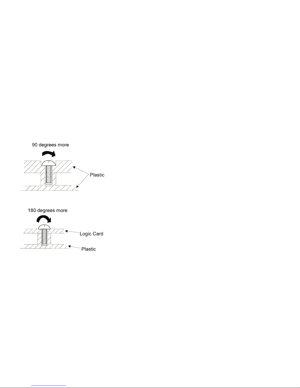
Screw Tightening Information
Loose screws can cause a reliability problem. The IBM
ThinkPad computer addresses this problem with
nylon-coated screws. Tighten screws as follows:
Plastic to plastic
Turn an additional 90 degrees after the screw head
touches the surface of the plastic part:
Logic card to plastic
Turn an additional 180 degrees after the screw head
touches the surface of the logic card:
Torque driver
If you have a torque driver, refer to the “Torque”
instruction with each step.
How to Use Error Messages: Use the error
codes displayed on the screen to diagnose failures. If
more than one error code is displayed, begin the diagnosis
with the first error code. Whatever caused the first error
code can result in false error codes being displayed. If no
error code is displayed, see if the error symptom is listed
in the “Symptom-to-FRU Index” on page 21.
Port Replicator Problems: If you suspect a
problem with the port replicator, see “Port Replicator
Checkout” on page 13.
How to Diagnose Multiple FRUs: When the
adapter or the device has more than one FRU, the error
code could be caused by any of them. Before replacing
multiple FRUs, try removing or exchanging each FRU, one
by one in the designated sequence, to see if the symptoms
change.
4
Page 7

What to Do First: The service personnel must fill in
the following information in the parts exchange form or
parts return form that is attached to the returned FRU:
1. Name and phone number of service personnel
2. Date of service
3. Date that the machine failed
4. Date of purchase
5. Failure symptoms, error codes appearing on the
display, and beep symptoms
6. Procedure index and page number in which the
failing FRU was detected
7. Failing FRU name and part number
8. Machine type, model number, and serial number
9. Customer's name and address
Before checking problems with the computer, determine
whether the damage is covered under the warranty by
referring to the following:
Note for Warranty: During the warranty period, the
customer may be responsible for repair costs if the
computer damage was caused by misuse,
accident, modification, unsuitable physical or
operating environment, or improper maintenance by
the customer. The following list provides some
common items that are not covered under warranty
and some symptoms that may indicate that the
system was subjected to stress beyond normal
use:
The following is not covered under the warranty:
LCD panel cracked by applying excessive for or
by being dropped
Scratched (cosmetic) parts
Cracked or broken plastic parts, broken latches,
broken pins, or broken connectors caused by
excessive force
Damage caused by liquid spilled into the system
Damage caused by improperly inserting a PC
Card or installing an incompatible card
Damage caused by foreign material in the FDD
Diskette drive damage caused by pressing the
diskette drive cover or inserting diskettes with
multiple labels
Damaged or bent diskette eject button
CD-ROM drive damage caused by shock from
excessive force, or by being dropped
Fuses blown by attaching a nonsupported device
Forgotten computer password (making the
computer unusable).
ThinkPad 560Z HMM 5
Page 8
The following symptoms might indicate damage
caused by nonwarranted activities:
Missing parts might be a symptom of
unauthorized service or modification.
HDD spindles can become noisy from being
subjected to excessive force or from being
dropped.
I9990303 errors can be caused by exposure to
strong magnetic fields.
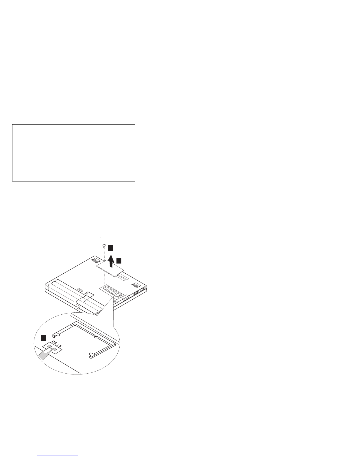
How to Disable the Power-On Password:
When Only the Power-on Password is Set.
1. Power off the computer.
2. Turn the computer upside down.
3. Loosen the DIMM socket lid screw 1 , and
remove the DIMM socket lid 2 .
4. Short the power-on password jumper pads
(R522) 3 .
1
2
3
5. Power on the computer and wait until the POST
ends. The password is cleared.
6. Reinstall the DIMM socket lid, and turn the
computer right side up.
7. Verify that the password prompt does not
appear.
8. To reactivate the password, set the password
again.
6
Page 9

When Both Power-on Password and Supervisor
Password are Set
1. Power off the computer.
2. Press and hold F1; then power on the computer.
After a few seconds, the password prompt
appears.
3. Enter your supervisor password. The
Easy-setup Main Menu appears.
4. Select Password and then Power on.A
rectangular box appears.
5. Enter your supervisor password and press the
Space bar once.
6. Press Enter twice.
7. Select Exit.
8. Select Restart on the Easy-Setup Main Menu
and wait until the POST ends.
9. Reinstall the DIMM socket lid, and turn the
computer right side up.
Verify that the password prompt does not appear.
To reactivate the password, set the password again.
Power Shutdown Switch: The Power Shutdown
switch resets the system regardless of the microcode
status and forces a power off. Use this push button to
power off when power is not completely off or when the
microcode is in a hung state.
See “Bottom View” on page 73 for the location of this
switch.
ThinkPad 560Z HMM 7
Page 10

Product Overview
The following table is an overview of the system features
of the IBM ThinkPad 560 series:
Feature Description
Processor 560X
Intel Pentium MMX 200 MHz, L2
cache
Intel Pentium MMX 233 MHz, L2
cache
560Z
Intel Pentium II 233 MHz, L2
cache
Intel Pentium II 300 MHz, L2
cache
Bus Architecture PCI Bus
Memory
(Standard)
Memory (Option) Maximum of 96MB for 560X.
CMOS RAM 560X/560Z
VGA Video 560X
Diskette Drive
(External)
Hard Disk Drive 560X
560X
32MB (on the system board)
560Z
32MB (on the system board)
64MB (on the system board)
Maximum of 96MB for 560Z when the
base memory is 32MB.
Maximum of 128MB for 560Z when the
base memory is 64MB.
242 bytes
12.1-inch, 256K colors 800×600
pixel DSTN color LCD
12.1-inch, 256K colors, 800×600
pixel TFT color LCD
560Z
12.1-inch, 16M colors, 800×600
pixel TFT color LCD
1.44MB (2-mode), 3.5-inch
1.44MB (3-mode), 3.5-inch, for
Japan
2.1GB, 2.5-inch, IDE interface
4.0GB, 2.5-inch, IDE interface
560Z
4.0GB, 2.5-inch, IDE interface
6.4GB, 2.5-inch, IDE interface
8
Page 11

Feature Description
I/O Port Serial
Audio 16-bit audio
Infrared Transfer 560X/560Z
PCMCIA One Type-III
AC Adapter 56 Watt type
Parallel
USB
External monitor
Headphone
Microphone
Port replicator
Internal speaker
Internal microphone
Mechanical volume (560X)
Software volume (560Z)
IrDA 1.1
or two Type-I / Type-II
560X/560Z
CardBus support
ThinkPad 560Z HMM 9
Page 12

Checkout Guide
Use the following procedure as a guide for computer
problems.
Note: The diagnostic tests are intended to test only IBM
products. Non-IBM products, prototype cards, or
modified options can give false errors and invalid
system responses.
1. Obtain the failing symptoms in as much detail as
possible.
2. Verify the symptoms by attempting to re-create the
failure by running the diagnostic test or by repeating
the same operation.
Note: To run the diagnostics, refer to “Running the
Diagnostics” on page 33.
3. Use the following table with the verified symptom to
determine which page to go to. Search the
symptoms column, and find the description that best
matches your symptom; then go to the page shown in
the “Go To” column.
Symptoms (Verified) Go To
Power failure (The
power indicator does not
go on or stay on).
POST does not
complete. No beep or
error codes are
indicated.
POST beeps, but no
error codes are
displayed.
POST detected an error
and displayed numeric
error codes.
The diagnostic test
detected an error and
displayed a FRU code.
The configuration is not
the same as the
installed devices.
Other symptoms (such
as LCD display
problems).
“Power Systems
Checkout” on page 14.
“Symptom-to-FRU
Index” on page 21, and
then use the No Beep
Symptoms table.
“Symptom-to-FRU
Index” on page 21, and
then use the Beep
Symptoms table.
“Symptom-to-FRU
Index” on page 21, and
then use the Numeric
Error Codes table.
“Running the
Diagnostics” on
page 33.
“Checking the Installed
Devices List” on
page 35.
“Symptom-to-FRU
Index” on page 21, and
then use the Other
Symptoms table.
10
Page 13

Symptoms (Verified) Go To
Symptoms cannot be
re-created (Intermittent
problems).
Use the
customer-reported
symptoms and go to
“Symptom-to-FRU
Index” on page 21.
Diskette Drive Checkout
Do the following to isolate the problem to a controller,
drive, or diskette. A blank, write-enabled, formatted 2HD
diskette is required.
FDD-1
represents an external diskette drive attached
through the external diskette drive connector.
represents the external diskette drive attached to the port
replicator.
Attention: Make sure that the diskette does not have more
than one label attached to it. Multiple labels can cause
damage to the drive or cause the drive to fail.
Do the following to select the test device:
See “Running the Diagnostics” on page 33 for details.
1. Go to the advanced diagnostic mode by pressing
Ctrl+A from the Easy-Setup test menu.
2. Click on Exit twice.
3. Click on FDD-1 or FDD-2 to start the test.
4. Insert the blank diskette when instructed and follow
the instructions on the screen.
5. If the controller test detects an error, FRU code 10
appears. Replace the system board.
6. If the controller test runs without errors, the drive
read/write tests start automatically. If a drive test
detects an error, FRU code 50 for FDD-1 or 51 for
FDD-2 appears. If the diskette itself is known to be
good, replace the drive.
7. If the FDD-2 test detects an error, move the drive to
the computer's diskette drive connector directly, if
possible, and test it again as FDD-1.
If no errors occur in the FDD-1 position, the drive is
not defective. Go to “Port Replicator Checkout” on
page 13 to isolate the port replicator problem.
FDD-2
Keyboard or Auxiliary Input Device
Checkout
If the internal keyboard does not work or an unexpected
character appears, make sure that the flexible keyboard
cable is firmly connected to the system board. If it is firmly
connected, then run the Keyboard Test. If an external
keyboard is connected, remove it before running the
ThinkPad 560Z HMM
11
Page 14

Keyboard Test for the internal keyboard. See “Running
the Diagnostics” on page 33 for details.
Note: When the Fn key is pressed, a black square briefly
appears.
If the Keyboard Test detects a keyboard problem, do the
following one at a time to correct the problem. Do not
replace a nondefective FRU:
Replace the flexible keyboard cable.
Replace the keyboard.
Replace the system board.
The following auxiliary input devices are supported for this
computer:
Numeric keypad
Mouse (PS/2 compatible)
External keyboard (with keyboard/mouse cable)
If any of these devices do not work, reseat the cable
connector and repeat the failing operation.
If the problem does not recur, the problem may have been
in the connector. Recheck the connector.
If the problem is not corrected, replace the device and then
the system board.
Memory Checkout
EDO DIMM cards are available for increasing the memory
capacity.
DIMM Displayed
No DIMM card
installed
8 MB
(not supported
by 560Z)
16 MB 48576 KB 81344 KB
32 MB 64960 KB 97728 KB
64 MB 97728 KB 130496 KB
Value
(32MB Base)
32192 KB 64960 KB
40384 KB 73152 KB
Displayed
Value
(64MB Base)
Memory errors might stop system operations, show error
messages on the screen, or hang the system.
Use the following procedure to isolate memory problems.
Note: Make sure that the DIMM card is fully installed into
the connector. A loose connection can cause an
error.
See “Running the Diagnostics” on page 33 for details.
1. Power off the computer and remove the DIMM card
from its slot (if installed).
12
Page 15

2. Press and hold the F1 key; then power on the
computer. Hold the F1 key down until the
Easy-Setup menu appears.
3. Select Test and press Enter.
4. Select Memory and press Enter to run the memory
test on base memory. If an error appears, replace
the system board.
5. Power off the computer and reinstall the DIMM card;
then power on the computer. Verify the memory size;
then test the memory. If an error appears, replace
the DIMM card.
If memory problems occur, use the loop option to repeat
the test. If the test detects an error, an error log will be
printed on the printer connected to the parallel port. See
“Displaying the Error Log” on page 34 for more
information.
Flash Memory Update: System setup programs
and diagnostic tests are stored in the flash memory. The
flash memory update is required for the following
conditions:
New versions of system programs
New features or options
To update the flash memory, do the following:
1. Get the appropriate diskette containing the update.
2. Insert the System Program Service Diskette into
drive A and power on the computer.
3. Select Update system programs from the menu.
Fan Checkout
To check the fan, do the following:
1. Start Easy-Setup.
2. Click on Test. The fan will start so you can check the
air turbulance at the fan louver.
3. Press Ctrl + A to enter the advanced diagnostic
mode. The ThinkPad FRU Connections window
appears. If the fan connector is not connected, the
Fan not connected message appears.
4. Click on Exit. The keyboard layout appears on the
screen.
5. Click on Exit again.
6. Click on System Board then press Enter to run the
test.
Follow the description in the window. If the test
detects a fan problem, replace it.
Port Replicator Checkout
Use the following procedure to isolate a port replicator
problem. The port replicator attaches to the system
expansion connector at the bottom of the computer.
1. Power off the computer.
ThinkPad 560Z HMM
13
Page 16

2. Remove the failing devices from the port replicator.
3. Unplug the AC adapter from the port replicator, if
attached.
4. Remove the port replicator from the computer.
5. Reconnect the failing device directly to the computer.
(If another device is already connected to the
computer, remove it first.)
6. Go to the “Running the Diagnostics” on page 33 and
run the diagnostics.
7. If the advanced diagnostic device test did not find an
error, suspect a problem with the port replicator of the
system expansion bus.
8. Power off the computer and reconnect the port
replicator.
9. Power on the computer and run the following
advanced diagnostic tests:
Serial port test with the wrap plug (P/N 72X8546)
installed on the port replicator
Universal serial bus test with the test cable (P/N
05K2580) [see “Universal Serial Bus (USB) Test”
on page 34]
Parallel port test with the wrap plug (P/N
72X8546) installed on the port replicator
PC Card (PCMCIA) test with the PC test card
(P/N 35G4703) installed
FDD-2 device test on the failing device with a
scratch diskette
10. If diagnostic errors appear, replace the port replicator
or the diskette drive. If the problem remains after the
replacement, replace the system board.
11. If power problem appears only when the port
replicator is used, replace the port replicator.
If power shutdown occurs intermittently when using PC
Card devices via a port replicator, suspect an over-current
problem. Some PC Card devices use more power; if the
maximum usage of each devices occurs simultaneously,
the total current will exceed the limit, thereby causing a
power shutdown. Isolate this problem by removing one of
the devices, and use the computer under the same
condition, and see whether a power shutdown occurs. Do
this procedure for all devices to determine the cause.
Power Systems Checkout
To verify the symptom of the problem, power on the
computer using each of the following power sources.
1. Remove the battery pack and the diskette drive.
2. Connect the AC Adapter and check that power is
supplied.
3. Disconnect the AC Adapter and install the charged
battery pack; then check that power is supplied by the
battery pack.
If you suspect a power problem, see the appropriate power
supply checkout in the following list:
14
Page 17

“Checking the AC Adapter” on page 15
“Checking Operational Charging”
“Checking the Battery Pack” on page 16
“Checking the Backup Battery” on page 16
Checking the AC Adapter: You are here
because the computer fails only when the AC Adapter is
used:
If the power problem occurs only when the port
replicator is used, replace the port replicator.
If the power-on indicator does not turn on, check the
power cord of the AC Adapter for correct continuity
and installation.
If the operational charge does not work, go to
“Checking Operational Charging.”
1. Unplug the AC Adapter cable from the computer and
measure the output voltage at the plug of the AC
Adapter cable. See the following figure:
Pin Voltage (V dc)
1 +14.5 to +17.0
2 Ground
If the voltage is not good, replace the AC Adapter.
If the voltage is within the range, do the following:
Replace the system board.
If the problem is not corrected, go to
“Undetermined Problems” on page 31.
Note: An audible noise from the AC Adapter does not
always indicate a defect.
Checking Operational Charging: To check
operational charging, use a discharged battery pack or a
battery pack that has less than 50% of the total power
remaining when installed in the computer.
Perform operational charging. If the battery status
indicator does not turn on, remove the battery pack and let
it return to room temperature. Reinstall the battery pack.
If the charge indicator still does not turn on, replace the
battery pack.
If the charge indicator still does not turn on, replace the
system board. Then reinstall the battery pack. If the
ThinkPad 560Z HMM 15
Page 18
reinstalled battery pack is not charged, go to the next
section.
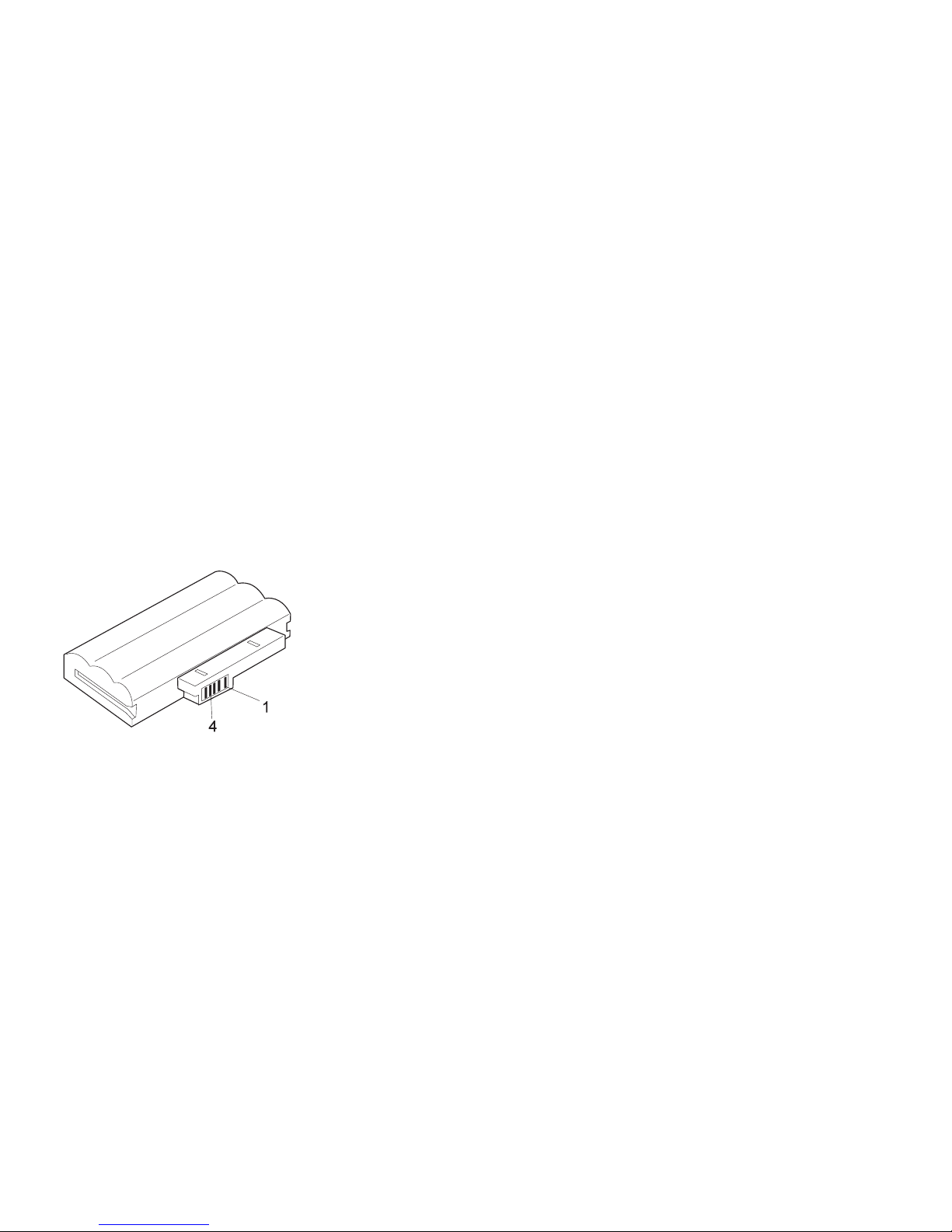
Checking the Battery Pack: Battery charging will
not start until the Fuel-Gauge shows that less than 95% of
the total power remains; with this condition the battery
pack will charge to 100% of its capacity. This protects the
battery pack from being overcharged or having a
shortened life.
Do the following:
1. Power off the computer.
2. Remove the battery pack and measure the voltage
between battery terminals 1 (+) and 4 (−). See the
following figure:
3. If the voltage is less than +11.0 V dc, the battery pack
has been discharged. Recharge the battery pack.
Note: In this case, the battery pack is
over-discharged. It takes the at least 2 hours
to recharge the battery pack even if the
indicator does not turn on.
If the voltage is still less than +11.0 V dc after
recharging, replace the battery pack.
4. If the voltage is more than +11.0 V dc, measure the
resistance between battery pack terminals 3 and 4.
The resistance must be 4 to 30 K ohm.
If the resistance is not correct, replace the battery
pack. If the resistance is correct, replace the system
board.
Checking the Backup Battery
1. Power off the computer and unplug the AC Adapter
from the computer.
2. Turn the computer upside down.
3. Remove the backup battery (see “1010 Backup
Battery” on page 45).
4. Measure the voltage of the backup battery. See the
following figure.
Note: Be careful not to measure the wrong side of
the backup battery.
16
Page 19
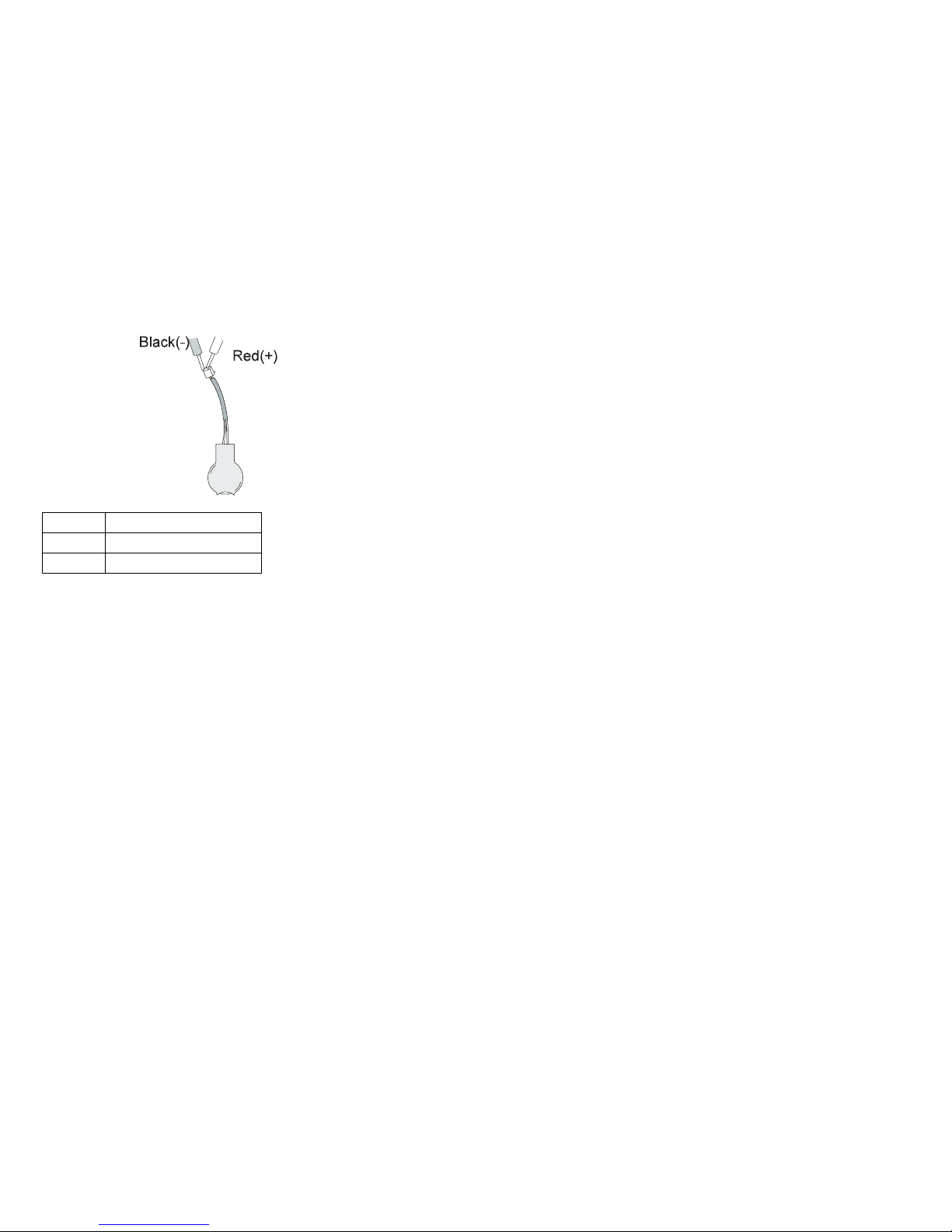
Wire Voltage (V dc)
Red +2.5 to +3.7
Black Ground
If the voltage is correct, replace the system board.
If the voltage is not correct, replace the backup
battery.
If the backup battery discharges quickly after
replacement, replace the system board.
Status Indicator Checkout
If an LED problem occurs, do the following:
1. Power off the computer.
2. Power on the computer.
3. All the LEDs in the indicator panel, except the Hard
Disk In Use LED, should turn on for a moment soon
after the computer is powered on. Make sure they
turn on.
If the problems persists, replace the system board.
System Board and CPU Mini-Cartridge
Checkout
The system board and the CPU mini-cartridge FRUs
perform the operation on the computer. Processor
problems can be caused by either FRU. Generally, the
CPU mini-cartridge has a lower failure rate. If a numeric
code indicates the system board or the CPU mini-cartridge
as failing, do the following procedure to isolate the
problem:
1. Run the system board test to verify the symptom.
This test verifies both the system board and the CPU
mini-cartrige. If no error is detected, return to
“Undetermined Problems” on page 31.
Note: Do not touch the keyboard and the pointing
device when the system board is being tested.
This might cause unexpected errors.
2. If FRU code 10 appears, replace the system board,
but do not replace the CPU mini-cartrige. Transfer
ThinkPad 560Z HMM
17
Page 20

the CPU mini-cartrige from the old system board to
the new system board.
3. If FRU code 11 appears, reseat the CPU
mini-cartridge.
4. Rerun the test to verify the fix.
5. If FRU code 11 remains, replace the CPU
mini-cartridge.
If this procedure does not correct the problem, go to
“Undetermined Problems” on page 31.
TrackPoint Checkout
If the TrackPoint does not work, do the following:
1. Run the ThinkPad Configurations program and check
if the TrackPoint is enabled.
2. If it is not, select Enable and enable it.
3. If you still have a problem, continue to the next step.
4. Go to the Easy-Setup menu.
5. Move to an item with the TrackPoint.
6. Press either the left or the right click button.
7. Verify that both buttons work correctly.
8. Move to another item with the TrackPoint.
9. Press the TrackPoint. (Press-to-Select).
10. Verify that the item is selected.
11. If the problem still persists, do the following one at a
Drifting Pointer
There may be cases when the pointer drifts for a
short while on the screen, this is not a hardware
problem. This movement can occur when a
slight, steady pressure is applied to the
TrackPoint. No service action needs to be taken.
time:
Warning: Do not replace a nondefective FRU.
Reseat the TrackPoint cable.
Replace the keyboard.
Replace the system board.
18
Page 21

Power Management Features
Three power management modes are provided by the
computer to reduce power consumption and prolong
battery power.
Standby Mode
In standby mode, the following occurs:
The LCD backlight turns off.
The hard disk drive motor stops.
The speaker is muted.
The computer enters standby mode when the Fn + F3
keys are pressed.
The computer exits standby and resumes normal operation
when any key is pressed.
Note: Standby mode in Windows 98 is called suspend
mode in Windows 95.
Suspend Mode
The following events occur in addition to what occurs in
standby mode when the computer enters suspend mode:
The LCD is powered off.
The hard disk drive is powered off.
The CPU stops.
Note: Suspend mode in Windows 95 is called standby
mode in Windows 98.
The following events cause the computer to enter suspend
mode:
The Fn + F4 keys are pressed.
The LCD cover is closed.
If you add a check mark to the Will not suspend
even if LCD is closed box in the “Power
Management Properties” window, the computer will
not enter suspend mode even if the LCD is closed.
The LCD only turns off.
The Suspend button is selected in the Fuel-Gauge
program.
The specified time has elapsed from the last
operation with the keyboard, the TrackPoint, the hard
disk drive, the parallel connector, or the diskette drive;
or the AC Adapter is plugged in.
In Windows 95, the timer is set by the Suspend
Timer in the “Power Properties” window.
In Windows 98, the timer is set by the System
standby timer in the “Power Management Properties”
window.
The battery indicator blinks orange indicating that the
battery power is low.
If you add a check mark to the Hibernate when
battery becomes low box in the “Power
ThinkPad 560Z HMM
19
Page 22

Management Properties” window, the computer enters
hibernation mode under this condition.
Note: In Windows 98, the Alarms setting in the
“Power Management Properties” window may
not be synchronous with the actual low battery
condition which shows a blinking then a
steady orange and may cause the alarm to
sound prematurely.
Note: The computer cannot enter suspend mode when it
is attached to a docking station.
The following events cause the computer to resume
operation from suspend mode:
The Fn key is pressed.
The LCD cover is opened.
The power switch is turned on.
The resume timer is set.
In Windows 95, you can set the time in the resume
on timer in the “Power Management Properties”
window.
In Windows 98, the Scheduled Tasks setting has
priority over the resume on timer in the “Power
Management Properties” window.
Note: The computer does not accept any event
immediately after it enters suspend mode.
Therefore, wait a few seconds before taking
any action to reenter operation mode.
Hibernation Mode
In hibernation mode, the following occurs:
The system status, RAM, VRAM, and setup data are
stored on the hard disk.
The system is powered off.
The following events cause the computer to enter
hibernation mode:
The Fn + F12 keys are pressed.
The Hibernation button is selected in the Fuel-Gauge
program.
The power switch is turned off and hibernation mode
is set to Hibernate by Power Switch???.
The timer conditions are satisfied in suspend mode
(for operating systems other than Windows 98).
A critically low battery condition occurs and
hibernation mode is set to Hibernate when battery
becomes low.
The computer exits hibernation mode and resumes
operation when the Power switch is pressed. When power
is turned on, the hibernation file in the boot record on the
hard disk drive is read and system status is restored from
the hard disk drive.
20
Page 23

Symptom-to-FRU Index
The Symptom-to-FRU Index is a list containing symptoms,
errors, the possible causes. The most likely cause is listed
first.
Note: Perform the FRU replacement or actions in the
sequence shown in the “FRU/Action in Sequence”
column. If a FRU replacement does not solve the
problem, put the original part back in the computer.
Do not replace a nondefective FRU.
This index can also help you determine the next possible
FRUs to be replaced when servicing a computer.
Numeric error codes show the errors detected in POST or
system operation. In the following error codes, X can be
any number.
If no codes are available, use narrative symptoms.
If the symptom is not listed, go to “Undetermined
Problems” on page 31.
Note: For IBM devices not supported by diagnostic
codes in the ThinkPad notebook computers,
see the manual for that device.
Numeric Error Codes
Symptom / Error FRU / Action in Sequence
10X
101 Interrupt
failure.
102 Timer failure.
103 Timer interrupt
failure.
104 Protected
mode failure.
105 Last 8042
command not
accepted.
107 NMI test
failure.
108 Timer bus test
failure.
109 Low meg-chip
select test.
110
(Planar parity.)
ThinkPad 560Z HMM 21
1. System board.
1. Go to “Memory
Checkout” on
page 12.
2. DIMM card.
3. Detach the expansion
unit if it is attached to
the computer.
4. System board.
Page 24

Symptom / Error FRU / Action in Sequence
111
(I/O parity.)
127
(Cache error)
158
(Hard disk password was
not set even though the
supervisor password is set.)
159
(Hard disk password is not
set the same as the
supervisor password.)
161
(Dead battery.)
163
(Time and date were not
set.)
173
(Configuration data was
lost.)
174
(Configuration error:
Perform“Checking the
Installed Devices List” on
page 35 before changing
any FRUs.)
175, 177, 178
175 EEPROM
CRC #1 error.
177 Supervisor
password
check sum
error.
178 EEPROM is
not functional.
183
(Incorrect password entered
at the supervisor password
prompt.)
184
(Power-on password check
sum error.)
1. Go to “Memory
Checkout” on
page 12.
2. Port replicator.
3. System board.
1. CPU mini-cartridge.
2. System board.
1. Set the password for
hard disk drive.
1. Set the correct
password for hard
disk drive.
1. Go to “Checking the
Backup Battery” on
page 16.
2. Backup battery.
3. System board.
1. Set time and date.
2. System board.
1. Select OK in the error
screen; then set the
time and date.
2. Backup battery.
3. System board.
1. Check device
configuration.
2. Hard disk drive
assembly.
3. System board.
1. System board.
1. Have the user
examine the
password.
1. Reset the power-on
password in
Easy-Setup.
22
Page 25

Symptom / Error FRU / Action in Sequence
185
(The startup sequence is
not valid. Suspect that
power was off when the
startup sequence was being
updated.)
186 1. System Board.
188
(EEPROM CRC #2 error.)
190
(A depleted battery pack
was installed when the
power was on.)
191XX
(PM initialization error.)
192
(A fan error.)
195
(The configuration read from
the hibernation area does
not match the actual
configuration.)
196
(A read error occurred in the
hibernation area of the hard
disk drive.)
199XX
(Resume error.)
1XX 1. System board.
225
(An unsupported memory
module.)
2XX
201 Memory data
error.
202 Memory line
error 00–15.
203 Memory line
error 16–23.
205 Memory test
failure on
on-board
memory.
221 ROM to RAM
remap error.
1. Reset the startup
sequence in
Easy-Setup.
1. System board.
1. Go to “Checking the
Battery Pack” on
page 16.
1. System board.
1. Fan.
2. System board.
1. Check if the
configuration was
changed.
For example, check if
a DIMM card was
added.
1. Run the hard disk
drive test.
2. Reseat the HDD flat
cable.
3. Hard disk drive.
1. System board.
1. Check if a supported
DIMM card is
installed.
2. DIMM card.
3. System board.
1. Go to “Memory
Checkout” on
page 12.
2. DIMM card.
3. System board.
ThinkPad 560Z HMM 23
Page 26

Symptom / Error FRU / Action in Sequence
301, 303, 304, 305, 3XX
301 Keyboard
error.
601, 6XX
601 Diskette drive
or controller
error.
602
(Diskette read error.)
604
(Unacceptable ID was read
from the diskette drive.)
11XX
1101 Serial_A test
failure.
12XX
1201 Serial_B test
failure.
17XX
1701 Hard disk
controller
failure.
1780, 1790 Hard disk 0
error.
1781, 1791 Hard disk 1
error.
1801
(An unsupported port
replicator.)
24XX
2401 System board
video error.
1. Go to “Keyboard or
Auxiliary Input
Device Checkout” on
page 11.
2. Keyboard.
3. External numeric
keypad.
4. External keyboard.
5. Keyboard/mouse
cable.
6. System board.
1. Go to “Diskette Drive
Checkout” on
page 11.
2. Diskette drive
assembly.
3. Diskette.
4. System board.
1. Go to “Diskette Drive
Checkout” on
page 11.
2. Diskette.
3. Diskette drive
assembly.
1. Go to “Diskette Drive
Checkout” on
page 11.
2. Diskette drive
assembly.
3. System board.
1. Serial device.
2. Communication cable.
3. System board.
1. System board
(infrared).
1. HDD flat cable.
2. Hard disk drive..
3. System board.
1. Make sure that the
correct port
replicator is
connected. See page
79.
1. System board.
24
Page 27

Symptom / Error FRU / Action in Sequence
808X
8081 PCMCIA
presence test
failure.
(PCMCIA
revision
number also
checked.)
8082 PCMCIA
register test
failure.
860X
(Pointing device error when
TrackPoint is disabled.)
8601 System bus
error–8042
mouse
interface.
8602 External
mouse error.
8603 System bus
error or
mouse error.
861X
(Pointing device error when
TrackPoint is enabled.)
8611 System bus
error–I/F
between 8042
and IPDC.
8612 TrackPoint
error.
8613 System board
or TrackPoint
error.
I9990301
I9990302
I9990305
I9990301 Hard disk
error.
I9990302 Invalid hard
disk boot
record.
I9990305 No bootable
device.
I9990303
(Bank–2 flash ROM check
sum error.)
1. PC Card slot
assembly.
2. PCMCIA device.
3. System board.
1. External mouse.
2. External keyboard.
3. System board.
1. Reseat the keyboard
cable on the system
board.
2. Keyboard.
3. External mouse.
4. System board.
1. Check that the
operating system is
installed in the hard
disk drive. If not,
install the operating
system.
2. Reseat the boot
device.
3. Reseat the HDD flat
cable.
4. Check the startup
sequence for the
correct boot device.
5. Check that the
operating system has
no failure and is
installed correctly.
1. System board.
ThinkPad 560Z HMM 25
Page 28

Symptom / Error FRU / Action in Sequence
Other codes not listed
above.
1. Go to “Undetermined
Problems” on
page 31.
26
Page 29

Beep Symptoms
Symptom / Error FRU / Action in Sequence
Continuous beeps. System board.
One beep and a blank,
unreadable, or flashing
LCD.
One beep, and the message
“Unable to access boot
source.”
One long and two short
beeps, and a blank or
unreadable LCD.
One long beep followed by
four short beeps each time
the Power switch is
operated.
(System cannot power on
due to low battery voltage.)
One beep every second.
(System is shutting down
due to low battery voltage.)
Two short beeps with error
codes.
Two short beeps with blank
screen.
1. Reseat the LCD
connector.
2. LCD assembly.
3. System board.
1. Boot device.
2. System board.
1. System board.
2. LCD assembly.
Connect the AC Adapter
or install a fully charged
battery.
Connect the AC Adapter
or install a fully charged
battery. (Allow the
system to completely shut
down before changing the
battery.)
POST error. See
“Numeric Error Codes” on
page 21.
System board.
No Beep Symptoms
Symptom / Error FRU / Action in Sequence
No beep, power-on indicator
not on, and a blank LCD
during POST.
No beep, power-on indicator
on, and a blank LCD during
POST.
No beep, power-on indicator
on, and a blinking cursor
only during POST.
No beep during POST but
system runs correctly.
ThinkPad 560Z HMM 27
1. Go to “Power
Systems Checkout”
on page 14.
2. System board.
3. CPU Mini-Cartridge.
4. Check the power
outlet.
1. System board.
2. CPU Mini-Cartridge.
1. System board.
2. CPU Mini-Cartridge.
1. Turn the volume up
and check the
speaker.
2. Speaker.
3. System board.
Page 30

Function-Related Symptoms
Symptom / Error FRU / Action in Sequence
The system does not
suspend or resume when
the LCD is closed or
opened.
The battery Fuel-Gauge
does not go higher than
90%.
The memory count (size)
appears different from
actual size.
The system configuration
does not match the installed
devices.
The system hangs
intermittently.
1. Go to “Suspend
Mode” on page 19,
and check that the
computer can enter
suspend mode.
2. Boot an operating
system and press
Fn+F4. If the
computer enters
suspend mode,
suspect that the
application program is
not working properly.
3. LCD assembly.
4. System board.
Go to “Checking the
Battery Pack” on page 16
and see the note.
Go to “Memory Checkout”
on page 12.
Go to “Checking the
Installed Devices List” on
page 35.
Go to “Intermittent
Problems” on page 31.
Indicator-Related Symptoms
Symptom / Error FRU / Action in Sequence
The indicator incorrectly
remains off or on, but
system runs correctly.
The battery power status
indicator blinks from green,
yellow, to orange.
The battery indicator does
not turn on when the battery
is installed.
28
System board.
1. Check that a correct
battery is installed.
2. Battery pack.
3. System board.
1. Battery pack.
2. System board.
Page 31

Infrared-Related Symptoms
Symptom / Error FRU / Action in Sequence
Unable to communicate
using the Infrared (IR) Port.
1. Make sure the setup
for the IR is correct.
Use the ThinkPad
Configurations utility.
2. Make sure there are
no fluorescent lights
near the computer.
The computer may
receive optical noise
from the fluorescent
light.
3. Run the advanced
diagnostic test. If an
error occurs and a
FRU code is displayed,
replace the parts
shown by the FRU
code.
Keyboard- or TrackPoint-Related
Symptoms
Symptom / Error FRU / Action in Sequence
The keyboard (one or more
keys) does not work.
The TrackPoint does not
work.
The pointer moves
automatically or does not
work correctly.
1. Reseat the keyboard
cable on the system
board.
2. Keyboard.
3. System board.
1. Reseat the keyboard
cable on the system
board.
2. Go to “TrackPoint
Checkout” on page 18.
3. Keyboard.
4. System board.
See “TrackPoint
Checkout” on page 18.
ThinkPad 560Z HMM 29
Page 32

LCD-Related Symptoms
Important
The TFT LCD for the notebook computer contains
over 2,359,296 thin-film transistors (TFTs). A small
number of missing, discolored, or lighted dots (on all
the time) is characteristic of TFT LCD technology, but
excessive pixel problems can cause viewing concerns.
The LCD should be replaced if the number of missing,
discolored, or lighted dots in any background is 21 or
more.
Symptom / Error FRU / Action in Sequence
No beep, power-on indicator
on, and a blank LCD during
POST.
LCD backlight not
working.
LCD too dark.
LCD brightness cannot
be adjusted.
LCD contrast cannot
be adjusted.
LCD screen
unreadable.
Characters missing
pels.
Screen abnormal.
Wrong color displayed.
LCD has extra horizontal or
vertical lines displayed.
1. Reseat the CPU
mini-cartridge.
2. System board.
1. Reseat the LCD
connectors.
2. LCD inverter card.
3. LCD assembly.
4. System board.
1. See important note
for “LCD-Related
Symptoms.”
2. Reseat all LCD
connectors.
3. LCD assembly.
4. System board.
LCD assembly.
Peripheral-Device-Related Symptoms
Symptom / Error FRU / Action in Sequence
The external monitor does
not work correctly.
Printer problems. 1. Run printer self-test.
Serial or parallel port device
problems.
30
Connect the external
monitor to another PC. If
the monitor works fine,
replace the system board.
If not, replace the external
monitor.
2. Parallel port wrap test.
3. System board.
4. Printer cable.
1. Run serial/parallel
port wrap test.
2. Device.
3. System board.
4. Device cable.
Page 33

Power-Related Symptoms
Symptom / Error FRU / Action in Sequence
Power shuts down during
operation.
The system does not power
off.
(See “Power Shutdown
Switch” on page 7.)
1. Go to “Power
Systems Checkout”
on page 14.
2. Battery pack.
3. Remove the battery
pack and let it cool for
2 hours.
4. System board.
5. Check the power
outlet.
1. Press the Power
Shutdown switch.
2. System board.
Other Symptoms
Symptom / Error FRU / Action in Sequence
Errors occur only when the
port replicator is used.
PC Card slot pin is
damaged.
Note: If you cannot find a symptom or an error in this list
and the problem remains, see “Undetermined
Problems.”
See “Port Replicator
Checkout” on page 13.
PC Card slots assembly.
Intermittent Problems
Intermittent system hang problems can be caused by a
variety of reasons that have nothing to do with a hardware
defect, such as: cosmic radiation, electrostatic discharge,
or software errors. FRU replacement should be
considered only when a recurring problem exists.
When analyzing the intermittent problem, do the following:
1. Run the advanced diagnostic test for the system
board in loop mode at least 10 times.
2. If no error is detected, do not replace any FRUs.
3. If any error is detected, replace the FRU shown by
the FRU code. Rerun the test to verify that no more
errors exist.
Undetermined Problems
You are here because the diagnostic tests did not identify
which adapter or device failed, installed devices are
incorrect, a short circuit is suspected, or the system is
inoperative. Follow these procedures to isolate the failing
FRU (do not isolate nondefective FRUs).
Verify that all attached devices are supported by the
computer.
ThinkPad 560Z HMM
31
Page 34

Verify that the power supply being used at the time of the
failure is operating correctly. (See “Power Systems
Checkout” on page 14):
1. Power off the computer.
2. Visually check them for damage. If any problems are
found, replace the FRU.
3. Remove or disconnect all of the following devices:
a. Non-IBM devices.
b. Devices attached to the port replicator.
c. Printer, mouse, and other external devices.
d. Battery pack.
e. Hard disk drive.
f. External diskette drive.
g. DIMM card.
h. PC cards.
4. Power on the computer.
5. Determine if the problem has changed.
6. If the problem does not recur, reconnect the removed
devices one at a time until you find the failing FRU.
7. If the problem remains, replace the following FRUs
one at a time. Do not replace a nondefective FRU.
a. System board.
b. LCD assembly.
c. CPU mini-cartridge.
32
Page 35

Running the Diagnostics
Use either the TrackPoint or the cursor move keys to
interact with the tests.
The following table lists the special tools used for the
diagnostics:
Tool Name Part Number
PC Test Card 35G4703
Tri-Connector wrap plug 72X8546
USB parallel test cable 05K2580
Use either the TrackPoint or the cursor move keys to
interact with the tests. The Enter key works the same as
selecting the OK icon to reply OK.
1. Press and hold F1; then power on the computer.
Hold F1 down until the Easy-Setup menu appears.
2. Click on Test. The basic diagnostic menu appears.
3. Click on a device to run the test. The test progress
screen appears; then OK appears under the tested
device icon when the test ends without any errors.
4. Start the Advanced Diagnostic test by pressing
Ctrl+A on the basic diagnostic menu. The ThinkPad
FRU connections window appears.
5. Click on Exit or press the Esc key. The keyboard
test window appears.
6. When you press a key, a mark appears or disappears
on the corresponding key position on the screen.
Repeat this step for any keys that need to be tested.
You can run the keyboard test if you press Ctrl+K
key at the advanced diagnostic menu.
7. To exit the keyboard test, click on Exit or press
Ctrl+Break. The Advanced Diagnostics menu
appears:
ThinkPad 560Z HMM 33
Page 36

8. Click on a device to test it, or click on Test All to test
all devices.
Click on Looptest to run the tests in a repeated loop.
The loop option menu appears. Click on a device;
the mark appears beside the selected device.
Repeat this step to select multiple devices. Click on
OK to start the diagnostic loop. If no device is
selected, all devices tests are looped.
9. To exit the loop, keep pressing Ctrl+Pause until the
test exits. A beep sounds to notify that the exit
interrupt is sensed by the test program. Press Esc to
exit from the loop test.
PC Card (PCMCIA) Slots Test
The green LED on the PC test card (P/N 35G4703) turns
on when the PC Card (PCMCIA) slot test is running. If the
LED does not turn on, check that the card is installed
correctly by reseating it. If the LED still does not turn on
after the card is reseated, try using another slot for the
test. If the LED still does not turn on and the test fails,
replace the FRU shown by the diagnostic error code.
Universal Serial Bus (USB) Test
At the advanced diagnostic test menu, connect the USB
parallel test cable (P/N 05K2580) to the computer shown
below:
1
2
Click on to run the test. Follow the instructions on
the screen. OK appears if the test passed, but three lines
of error codes appear if the test failed. The defective FRU
must be the system board.
Use the cable number 2 for an external USB port, such as
a port replicator.
Displaying the Error Log
Diagnostic errors are printed on a printer that is attached
to the parallel port when the error is detected. The error is
also logged in the system memory.
34
Page 37

Use the following procedure to display the errors:
1. Enter the advanced diagnostic test.
2. Press Ctrl+E.
3. The error log appears.
4. To exit the screen, click on Exit or press Esc key.
The error log is not saved when system power is turned
off.
Checking the Installed Devices List
If a device is installed but the icon appears in a gray shade
rather than a dark shade on the basic diagnostics test
menu, the device is defective. Reseat the device
connectors. If the symptom remains, replace the device or
the system board.
If a device that is not installed appears in a dark shade (for
no
example, FDD-2 appears in a dark shade when
FDD is installed), do the following:
1. Replace the first device in the configuration, such as
an FDD-1.
2. If the problem persists, replace the system board.
The Parallel, and Serial icons are always displayed in a
dark shade, because the icons represent subsystems of
the system board and not the attachment of the devices.
The FDD-1 icon represents the first drive in the system
configuration for each type of device. For Model 560Z,
FDD-1 represents an external diskette drive attached
through the external diskette drive connector. Similarly,
the FDD-2 icon represents the second drive, usually
attached through a port replicator.
second
ThinkPad 560Z HMM 35
Page 38

Diagnostic Error Codes
If an error is detected, the following appears:
Large X on the left side of the device icon.
Device ID (three digits).
Error code (two digits).
FRU code (four digits).
The device ID and error code indicate the detailed portion
of the FRU that caused the error. If replacing a FRU does
not correct the problem, see the device ID or error code
from the previous failure. If they have changed, the cause
might be that the new FRU is detective or that the FRU
was incorrectly installed.
Device ID: If an error is detected by the diagnostic
tests, a three-digit device ID is displayed, indicating the
suspected device.
Icon Device ID Suspected Device
001 System board
003 Keyboard
007 Math coprocessor
086 Pointing device
002 Memory
050 VGA display
054 Neomagic display
017 Hard disk drive
36
CPU mini-cartridge
Page 39

Icon Device ID Suspected Device
FDD-2
006 External diskette drive
2
066 External diskette drive
080 PCMCIA
or FDD connector of the
computer
or FDD Connector of the
port replicator
088 External PC Card
009 Parallel port
011 Serial port
154 Universal serial bus
155 External universal serial
103 IR
153 Audio (Crystal)
(PCMCIA)
(USB)
bus (USB)
ThinkPad 560Z HMM 37
Page 40

FRU Codes: If an error is detected by the diagnostic
tests, a four-digit FRU code is displayed. The FRU code
indicates two suspected FRUs. Replace the FRU that is
indicated by the
FRU that indicated by the
is assigned to code 00. If only one FRU is suspected, the
other FRU code is filled with zeros. See the reference
page before replacing the FRU.
FRU Code FRU
10 System board
11 CPU Mini Cartridge
20 Memory (See “Memory Checkout” on
30 Reserved
32 External keyboard
33 External mouse
34 AC Adapter
35 Speaker
36 Battery pack
38 Fan
40 LCD assembly
45 External monitor
50 1. Reseat the diskette drive (FDD-1)
51 1. Reseat the diskette drive (FDD-2)
60 1. Reseat the hard disk drive
70 Port replicator (PC Card)
72 PC Card slot assembly
73 Port replicator (USB)
two leftmost digits
two rightmost digits.
page 12.)
2. Diskette drive (FDD-1)
2. Diskette drive (FDD-2)
2. Hard disk drive
first; then replace the
No FRU
If the problem persists after replacement of the FRUs, go
to “Undetermined Problems” on page 31.
38
Page 41

Related Service Procedures
This section provides information about the following:
“Status Indicators”
“Password Combinations” on page 40
“Running a Low-Level Format” on page 40
“Fn Key Combinations” on page 41
Status Indicators
The system status indicators show the current computer
status in different colors (green and orange):
1
A
ThinkPad 560Z HMM 39
Page 42

Symbol Color Meaning
1 Battery Green The battery is fully charged.
Orange The battery is being charged.
2 Hard Disk
In Use
Blinking
orange
Orange Data is being read from or
The battery needs to be
charged.
written to the hard disk drive.
3 Numeric
Lock
4 Caps
Lock
5 Scroll
Lock
6 Suspend
Mode
7 Power On Green Power on
Green The numeric keypad on the
Green Caps lock mode is enabled.
Green The arrow keys can be used
Green Suspend mode
Blinking
Green
keyboard is enabled.
as screen-scroll function
keys.
Entering suspend mode or
hibernation mode, or is
resuming normal operation.
Password Combinations
The Model 560Z supports the following passwords:
Power-on password (POP)
Hard disk password (HDP)
Supervisor password (PAP)
The password combinations are:
When the
prompt appears, but the HDP prompt does not
appear.
When the
prompts appear.
When the
enabled but the HDP prompt does not appear. The
HDP is then set to the same password as the PAP.
POP
is the same as the
POP
is not the same as the
PAP
is used, the
HDP
HDP
is automatically
, a POP
HDP
, all of the
Running a Low-Level Format
Do the following to format the hard disk.
Attention: Make sure the drive address to be formatted is
correct. This procedure erases all information on the disk.
1. Power off the computer.
2. Press and hold F1; then power on the computer.
40
Page 43

3. Hold F1 until the Easy-Setup menu appears.
4. Click on the Test icon. The basic diagnostic menu
appears.
5. Press Ctrl + A to enter Advanced Diagnostics mode.
The ThinkPad FRU Connections menu appears.
6. Click on Exit. The Keyboard Test menu appears.
7. Click on Exit again.
8. Press Ctrl + L. The Low Level Format menu
appears.
9. Follow the instructions on the menu.
Fn Key Combinations
The following table shows the Fn key and function key
combinations and their corresponding functions.
The Fn key works independently from the operating
system. The operating system obtains the status through
the system management interface to control the system.
Fn + Description
F1 Reserved
F2 Fuel-Gauge display on or off
F3 Invokes standby mode
F4 Invokes suspend mode
F5 Reserved
F6 Reserved
F7 Switches between the LCD and an external
F8 Switches between screen expansion on and
F9 Reserved
F10 Reserved
F11 In Window 98, you can change only the CPU
F12 Invokes hibernation mode
monitor
off (no symbol on the key)
speed.
For other operating systems, this key
switches the power management mode
between;
High Performance, Automatic, and
Customized.
ThinkPad 560Z HMM 41
Page 44

FRU Removals and Replacements
This section contains information about removals and
replacements.
Do not damage any part. Only certified and trained
personnel should service the computer.
The arrows in the “Removals and Replacements”
section show the direction of movement to remove a
FRU, or to turn a screw to release the FRU. The
arrows are marked in numeric order, in square
callouts, to show the correct sequence of removal.
When other FRUs must be removed before the failing
FRU is removed, they are listed at the top of the
page.
To replace a FRU, reverse the removal procedure
and follow any notes that pertain to replacement.
See “Locations” for internal cable connections and
arrangement information.
When replacing a FRU, use the correct screw size as
shown in the procedures.
CAUTION:
Before removing any FRU, power off the computer,
unplug all power cords from electrical outlets, remove
the battery pack, and then disconnect any
interconnecting cables.
CAUTION:
The battery pack contains small amounts of nickel. Do
not disassemble it, throw it into fire or water, or
short-circuit it. Dispose of the battery pack as
required by local ordinances or regulations.
Attention: Before the computer is powered on after FRU
replacement, make sure all screws, springs, or other small
parts are in place and are not left loose inside the
computer. Verify this by shaking the computer and
listening for rattling sounds. Metallic parts or metal flakes
can cause electrical short circuits.
Attention: The system board is sensitive to, and can be
damaged by, electrostatic discharge. Establish personal
grounding by touching a ground point with one hand before
touching these units.
An electrostatic discharge (ESD) strap (P/N 6405959) must
be used to establish personal grounding.
Important Notice
This computer uses special nylon-coated screws with the
following characteristics:
They maintain tight connections.
They do not easily come loose, even with shock or
vibration.
But:
They need additional force to tighten.
42
Page 45

They should be used only once.
Do the following when you service this machine:
Keep the screw kit (P/N 12J0808) in your tool bag.
Always use new screws.
Use a torque screwdriver if you have one.
FRU Service Procedures
Review the following procedures before replacing any
FRUs.
Replacing the System Board
Restoring the System Unit Serial Number
The system unit serial number is written on the label
attached to the bottom cover of the computer and is also
stored as vital product data (VPD) in the EEPROM on the
system board.
When you replace the system board, you must set the
system unit serial number on the new system board to its
original number as follows:
1. Press and hold F1 and power on the computer.
2. Hold down F1 until the Easy-Setup menu appears.
3. Click on Config.
4. Press Ctrl + N. The System Unit Serial Number
menu appears.
5. Follow the instructions on the menu.
Notes:
1. Do not power-off the computer during the restoring
process.
Updating the Universally Unique IDentifier (UUID)
The Universally Unique IDentifier (UUID) is a 128-bit
number uniquely assigned to your computer at production
and stored in the EEPROM of your system board. The
algorithm that generates the unique number is designed to
provide unique IDs until the year 3400 A.D. Consequently,
no two computers in the world have the same number.
When you replace the system board, you must set the
UUID on the new system board as follows:
1. Press and hold F1 and power on the computer.
2. Hold down F1 until the Easy-Setup menu appears.
3. Click on Config.
4. Press Ctrl + G. The UUID menu appears.
5. Press F5 to generate a new UUID and press Enter to
overwrite it to the EEPROM.
ThinkPad 560Z HMM
43
Page 46

Removal Reference
Refer to the following chart for going to the removal
procedure:
Ref. No. FRU Page
1010 Backup Battery 45
1020 DIMM Card 46
1030 Battery Pack 47
1040 Hard Disk Driver 48
1050 Keyboard Bezel 49
1060 Keyboard Unit 52
1070 LCD Assembly 53
1080 Speaker 55
1081 HDD Flat Cable 56
1090 PC Card Slot Assembly 57
1100 Heat Sink 58
1110 CPU Mini Cartridge 59
1120 Fan 61
1130 System Board 62
2010 LCD Front Cover 64
2020 LCD Panel 66
2030 LCD Inverter Card 67
2040 LCD Cable and Hinges 68
3010 ThinkPad Port Replicator
with Advanced EtherJet
Feature
No.
70
44
Page 47

1010 Backup Battery
CAUTION:
The backup battery is a lithium battery and can cause
a fire, an explosion, or severe burns. Do not recharge
it, remove its polarized connector, disassemble it, heat
it above 100°C (212°F), incinerate it, or expose its cell
contents to water. Dispose of the battery as required
by local ordinances or regulations. Use of an
incorrect battery can result in ignition or explosion of
the battery. Replacement batteries can be ordered
from IBM or IBM Authorized Dealers.
Turn the computer upside down.
1
2
3
Note: When putting back the battery, connect the battery
connector using a small screwdriver and place the
battery in a slanted position.
Step Size (Quantity) Torque
1 M2.5 x 7 mm, black bind (1) 4 kgcm
When re-installing: Make sure you use the correct screw,
and tighten it firmly to the torque shown in the table if you
have a torque screwdriver. Never use a screw that you
removed. Use a new one. Make sure the screw is
tightened firmly (see “Screw Tightening Information” on
page 4 if you do not have a torque screwdriver).
ThinkPad 560Z HMM 45
Page 48

1020 DIMM Card (If Installed)
Turn the computer upside down.
1
2
4
3
3
Step Size (Quantity) Torque
1 M2.5 x 7 mm, black pan-head (1) 4 kgcm
When re-installing: Make sure you use the correct screw,
and tighten it firmly to the torque shown in the table if you
have a torque screwdriver. Never use a screw that you
removed. Use a new one. Make sure the screw is
tightened firmly (see “Screw Tightening Information” on
page 4 if you do not have a torque screwdriver).
46
Page 49

1030 Battery Pack
Turn the computer upside down.
1
2
ThinkPad 560Z HMM 47
Page 50

1040 Hard Disk Drive
Warning
Do not drop or apply any shock.
Do not apply pressure to the cover.
Do not touch the connector.
The hard disk drive is sensitive. Incorrect handling
can cause damage and permanent loss of data on the
hard disk. Before removing the hard disk drive, make
a backup copy of all the data on the hard disk. Never
remove the drive while the system is operating, in
suspend mode, or in hibernation mode.
Note:
For 560X, if you are replacing a 4GB hard disk
drive, reuse the shield and the tape (P/N 05K4690).
Battery Pack (1030)
1
2
3
Step Size (Quantity) Torque
1 M3 x 4 mm, coin screw (1) 4 kgcm
When re-installing: Make sure you use the correct screw,
and tighten all screws firmly to the torque shown in the table if
you have a torque screwdriver. Never use a screw that you
removed. Use a new one. Make sure the screws are
tightened firmly (see “Screw Tightening Information” on
page 4 if you do not have a torque screwdriver).
48
Page 51

1050 Keyboard Bezel
Battery Pack (1030)
3
3
Step Size (Quantity) Torque
1 M2.5 x 14 mm, black bind (1) 3 kgcm
2 M2.5 x 10 mm, black bind (3) 4 kgcm
3 M2.5 x 7 mm, black bind (7) 4 kgcm
When re-installing: Make sure you use the correct screw,
and tighten all screws firmly to the torque shown in the table if
you have a torque screwdriver. Never use a screw that you
removed. Use a new one. Make sure the screws are
tightened firmly (see “Screw Tightening Information” on
page 4 if you do not have a torque screwdriver).
2
1
ThinkPad 560Z HMM 49
Page 52

4
6
5
Latch
7
7
7
50
7
Page 53

10
8
You can easily disassemble the LCD release latch. To
reassemble it, do as shown:
9
ThinkPad 560Z HMM 51
Page 54

1060 Keyboard Unit
Battery Pack (1030)
Keyboard Bezel (1050)
After removing the screws 1 , remove the left and right
hinge support brackets 2 , the three brackets 3 , and the
gasket 4 .
When re-installing
1
3
2
3
4
2
3
When re-installing
Suspend Switch
Step Size (Quantity) Torque
1 M2.5 x 4 mm, black plain-head (5) 4 kgcm
When re-installing: Make sure you use the correct screw,
and tighten all screws firmly to the torque shown in the table if
you have a torque screwdriver. Never use a screw that you
removed. Use a new one. Make sure the screws are
tightened firmly (see “Screw Tightening Information” on
page 4 if you do not have a torque screwdriver).
52
Page 55

1070 LCD Assembly
Battery Pack (1030)
Keyboard Bezel (1050)
Note: For the LCD Assembly removal and replacement,
go to “2010 LCD Front Cover” on page 64.
5
2
3
4
When re-installing
Step Size (Quantity) Torque
1 M2.5 x 7 mm, black plain-head (2) 4 kgcm
2 M2.5 x 5 mm, yellow bind (2) 4 kgcm
ThinkPad 560Z HMM 53
Page 56

Step Size (Quantity) Torque
3 M2.5 x 2 mm, yellow bind (1) 2 kgcm
When re-installing: Make sure you use the correct screw,
and tighten all screws firmly to the torque shown in the table if
you have a torque screwdriver. Never use a screw that you
removed. Use a new one. Make sure the screws are
tightened firmly (see “Screw Tightening Information” on
page 4 if you do not have a torque screwdriver).
54
Page 57

1080 Speaker
Battery Pack (1030)
Keyboard Bezel (1050)
ThinkPad 560Z HMM 55
Page 58

1081 HDD Flat Cable
Battery Pack (1030)
Keyboard Bezel (1050)
1
2
Step Size (Quantity) Torque
1 M2.5 x 5 mm, yellow bind (3) 3 kgcm
When re-installing: Make sure you use the correct screw,
and tighten all screws firmly to the torque shown in the table if
you have a torque screwdriver. Never use a screw that you
removed. Use a new one. Make sure the screws are
tightened firmly (see “Screw Tightening Information” on
page 4 if you do not have a torque screwdriver).
56
Page 59

1090 PC Card Slot Assembly
Battery Pack (1030)
Keyboard Bezel (1050)
Note: Before removing and replacing the PC Card slot
assembly, make sure that the PC Cards are
removed and the eject levers are not sticking out.
Step Size (Quantity) Torque
1 M2.5 x 4 mm, black bind (4) 4 kgcm
When re-installing: Make sure you use the correct screw,
and tighten all screws firmly to the torque shown in the table if
you have a torque screwdriver. Never use a screw that you
removed. Use a new one. Make sure the screws are
tightened firmly (see “Screw Tightening Information” on
page 4 if you do not have a torque screwdriver).
ThinkPad 560Z HMM 57
Page 60

1100 Heat Sink
Battery Pack (1030)
Keyboard Bezel (1050)
Step Size (Quantity) Torque
1 M2 x 4 mm, yellow pan-head (4) 2 kgcm
When re-installing: Make sure you use the correct screw,
and tighten all screws firmly to the torque shown in the table if
you have a torque screwdriver. Never use a screw that you
removed. Use a new one. Make sure the screws are
tightened firmly (see “Screw Tightening Information” on
page 4 if you do not have a torque screwdriver).
58
Page 61

1110 CPU Mini Cartridge
Battery Pack (1030)
Keyboard Bezel (1050)
Heat Sink (1100)
When removing:
In order to avoid damaging the CPU cartridge, do not tilt it
for more than 10 mm from the system board.
1
Max. 10 mm
2
3
ThinkPad 560Z HMM 59
Page 62

When re-installing:
1. Do not touch the connector pins.
2. Do not touch the module.
3. Place the CPU mini cartridge on the system board so
the the screw holes align with posts A, B, C, and D
on the system board.
4. Press and hold down Area 1 1 ; then, press Area 2
2 .
5. Apply grease (0.2 grams) over the module.
B
D
A
Connector Pins
C
Module
1
Area 1
2
Area 2
60
Page 63

1120 Fan
Battery Pack (1030)
Keyboard Bezel (1050)
Heat Sink (1100)
Apply grease (0.2 grams) over the module. Refer to step
5 on page 60 for the location of the module.
Notes:
1. Do not touch the rotor or the blade of the fan when
assembling or disassembling. You may break it.
2. Do not pinch the fan cable when re-installing the fan.
Step Size (Quantity) Torque
1 M2 x 8 mm, yellow flat-head (2) 2 kgcm
When re-installing: Make sure you use the correct screw,
and tighten all screws firmly to the torque shown in the table if
you have a torque screwdriver. Never use a screw that you
removed. Use a new one. Make sure the screws are
tightened firmly (see “Screw Tightening Information” on
page 4 if you do not have a torque screwdriver).
ThinkPad 560Z HMM 61
Page 64

1130 System Board
DIMM (If Installed) (1020)
Battery Pack (1030)
Hard Disk Drive (1040)
Keyboard Bezel (1050)
LCD Assembly (1070)
Speaker (1080)
HDD Flat Cable (1081)
PC Card Slot Assembly (1090)
Heat Sink (1100)
CPU Mini Cartridge (1110)
Fan (1120)
Apply grease (0.2 grams) over the module. Refer to step
5 on page 60 for the location of the module.
Notes:
1. The system unit serial number must be restored when
the system board is replaced. Select the option Set
system identification on the maintenance diskette.
The flash ROM on the system board contains the vital
product data (VPD)—that is, the system unit serial
number, system board system number, and other
computer-unique data.
2. Do not power off the computer when restoring the
VPD. The system unit serial number label is attached
to the base cover.
Step Size (Quantity) Torque
2
3 M2 x 3 mm, yellow pan-head (2) 1.5 kgcm
When re-installing: Make sure you use the correct screw,
and tighten all screws firmly to the torque shown in the table if
you have a torque screwdriver. Never use a screw that you
removed. Use a new one. Make sure the screws are
tightened firmly (see “Screw Tightening Information” on
page 4 if you do not have a torque screwdriver).
Hex stud screw, silver hex-head
(6)
4 kgcm
62
Page 65

4
5
7
Step Size (Quantity) Torque
5 M2.5 x 4 mm, black bind (4) 4 kgcm
When re-installing: Make sure you use the correct screw,
and tighten all screws firmly to the torque shown in the table if
you have a torque screwdriver. Never use a screw that you
removed. Use a new one. Make sure the screws are
tightened firmly (see “Screw Tightening Information” on
page 4 if you do not have a torque screwdriver).
6
ThinkPad 560Z HMM 63
Page 66

2010 LCD Front Cover
Battery Pack (1030)
Keyboard Bezel (1040)
Keyboard Unit (1050)
LCD Assembly (1060)
Important
The LCD for the notebook computer contains over
2,359,296 thin-film transistors (TFTs). A small number
of missing, discolored, or constantly lighted dots is
characteristic of TFT LCD technology, but excessive
pixel problems can cause viewing concerns. The LCD
should be replaced if the number of missing,
discolored, or lighted dots in any background is 21 or
more.
Step Size (Quantity) Torque
2
When re-installing: Make sure you use the correct screw,
and tighten all screws firmly to the torque shown in the table if
you have a torque screwdriver. Never use a screw that you
removed. Use a new one. Make sure the screws are
tightened firmly (see “Screw Tightening Information” on
page 4 if you do not have a torque screwdriver).
M2.5 x 5.5 mm, brass flat-head
(3)
3 kgcm
64
Page 67

The LCD front cover has several latches. Release
the latches as shown in step 3 .
4
3
When re-installing
Reverse side
When re-installing:
Make sure that all eight hooks are engaged
properly.
Make sure that the slide knobs work correctly.
4
Hooks
ThinkPad 560Z HMM 65
Page 68

2020 LCD Panel
Battery Pack (1030)
Keyboard Bezel (1040)
Keyboard Unit (1050)
LCD Assembly (1060)
LCD Front Cover (2010)
1
4
4
3
When re-installing
1
2
Step Size (Quantity) Torque
1
When re-installing: Make sure you use the correct screw,
and tighten all screws firmly to the torque shown in the table if
you have a torque screwdriver. Never use a screw that you
removed. Use a new one. Make sure the screws are
tightened firmly (see “Screw Tightening Information” on
page 4 if you do not have a torque screwdriver).
M2.5 x 5.5 mm, brass flat-head
(4)
3 kgcm
66
Page 69

2030 LCD Inverter Card
Battery Pack (1030)
Keyboard Bezel (1040)
Keyboard Unit (1050)
LCD Assembly (1060)
LCD Front Cover (2010)
LCD Panel (2020)
Step Size (Quantity) Torque
M2.5 x 3.0 mm, brass flat-head
2
(2)
When re-installing: Make sure you use the correct screw,
and tighten all screws firmly to the torque shown in the table if
you have a torque screwdriver. Never use a screw that you
removed. Use a new one. Make sure the screws are
tightened firmly (see “Screw Tightening Information” on
page 4 if you do not have a torque screwdriver).
3 kgcm
Warning: Be careful of high voltage on the cable.
Connect the LCD connector firmly to the inverter
card by lining them up straight:
ThinkPad 560Z HMM 67
Page 70

2040 LCD Cable and Hinges
DIMM (If Installed) (1020)
Battery Pack (1030)
Keyboard Bezel (1040)
Keyboard Unit (1050)
LCD Assembly (1060)
LCD Front Cover (2010)
LCD Panel (2020)
12: LCD cable
34: Hinges
3
4
When re-installing the
LCD cable, see the next page.
1
2
Copper Tape
4
3
When re-installing the
left hinge, see the next page.
Step Size (Quantity) Torque
1
3
When re-installing: Make sure you use the correct screw,
and tighten all screws firmly to the torque shown in the table if
you have a torque screwdriver. Never use a screw that you
removed. Use a new one. Make sure the screws are
tightened firmly (see “Screw Tightening Information” on
page 4 if you do not have a torque screwdriver).
M2.5 x 5.5 mm, brass flat-head
(2)
M2.5 x 5.5 mm, brass flat-head
(3)
3 kgcm
3 kgcm
68
Page 71

When re-installing:
See the following figure:
If you are replacing hinges of the TFT panel, put a
spacer (P/N 05K4658) on the left hinge as shown
below:
Copper
Tape
ThinkPad 560Z HMM 69
Page 72

3010 ThinkPad Port Replicator with
Advanced EtherJet Feature
Step Size (Quantity) Torque
1
3
When re-installing: Make sure you use the correct screw,
and tighten all screws firmly to the torque shown in the table if
you have a torque screwdriver. Never use a screw that you
removed. Use a new one. Make sure the screws are
tightened firmly (see “Screw Tightening Information” on
page 4 if you do not have a torque screwdriver).
M2.5 x 5.5 mm, brass flat-head
(2)
M2.5 x 5.5 mm, brass flat-head
(3)
3 kgcm
3 kgcm
5
6
5
70
Page 73

Upper Cover
Assembly
Box Assembly
7
When re-installing
ThinkPad 560Z HMM 71
Page 74

Locations
Front View
1 LCD
2 Brightness Control
3 Headphone Jack
4 Microphone/Line-In Jack
5 Infrared Port
6 PC Card Slots
7 PC Card Eject Buttons
8 Battery Pack
9 TrackPoint, Left and Right Buttons
1 LCD Latch
11 Fn Key
12 Keyboard
13 Indicator Panel
14 Built-in Microphone
13
11
10
12
14
1
2
3
4
5
9
8
6
7
72
Page 75

Bottom View
1 System-Expansion Connectors
2 Security Keyhole
3 Memory Slot
4 Hard Disk Drive Slot
5 Battery Pack
6 Battery Pack Latch
7 Backup Battery Slot
8 Power Shutdown Switch
7
8
1
6
2
2
3
5
4
ThinkPad 560Z HMM 73
Page 76

Rear View
1 External Diskette Drive Connector
2 Fan Louver
3 Power Switch
4 Security Keyhole
5 Power Jack
6 External-Input-Device Connector
7 Universal Serial Port
8 Serial Connector
9 Parallel Connector
1 External Monitor Connector
11 Connector Cover
11
1
2
3
4
8
8910
74
567
Page 77

Parts List for Model 560Z
19
2
2
2
2
10
9
1
2
2
2
3
4
18
17
20
16
15
20
20
20
8
5
6
7
11
12
13
20
21
14
ThinkPad 560Z HMM 75
Page 78

Ref No. FRU Name FRU No.
1 LCDAssembly
(See LCD Assembly on page 77.)
2 Keyboard Bezel Kit includes: 05K5424
Keyboard Bezel Assembly
Hinge Support Bracket (Left & Right)
Keyboard Bracket (3 Pcs)
Gasket
3 Keyboard (
See Keyboards on page 78.)
4 TrackPointCap 84G6536
5 Speaker 05K5421
6 EMI Bracket I/O 46H4032
7 System Board (32MB) 10L1145
System Board (64MB) 10L1164
8 CPU Mini Cartridge (233 MHz) 10L1023
CPU Mini Cartridge (300 MHz) 10L1150
9 Fan 05K5420
10 HeatSink 05K5418
11 Card-BusSlot 05K5422
12 Rubber Cap I/O 46H4151
13 BaseCover 05K5417
14 PC Card Cover 12J1691
15 BackupBattery 12J1695
16 FDD Connector Cover 12J1692
17 Hard Disk Drive Assembly
4.0GB HDD Assembly (9.5 mm) 22L0024
withSpacer
4.0GB HDD Assembly (12.5 mm) 83H7085
6.4GB HDD Assembly (12.5 mm) 83H7103
18 HDD Flat Cable 05K2759
19 BatteryPack 46H4144
20 MechanicalParts 05K5423
HDDLid
Power Switch Knob
DIMM Socket Lid
Backup Battery Compartment Lid
Bracket Battery Guide
21 ScrewKit 05K5419
Screw M2-L4 -MC/Heat Sink(10) 4761072
Screw M2-L8 -Fan(10) 4761170
ScrewM2-L2(10) 05K5571
ScrewM2.5-L2(10) 05K5572
ScrewM2.5-L11(10) 05K5575
HDD Screw Kit 05K6073
External FDD (2-mode) 10H4056
External FDD (3-mode) 39F2086
External FDD Cable 12J1711
AC Adapter (56W)
2-pin 11J8974
3-pin 11J8956
Screw Cap, Front 66G5046
Screw Cap, Bottom 11J8919
76
Page 79

LCD Assembly
7
5b
1
2
3
4
5a
6
Ref. No. FRU Name FRU No.
1 LCD Cover Set 05K4602
2 Control Knob 12J9664
3 LCD Panel 05K9353
4 LCD Inverter Card 10L0916
5 Shield Kit 05K5656
a.Inverter Shield
b.LCD Shield
6 LCD Cable 05K2794
7 Hinge Left/Right 05K5657
ThinkPad 560Z HMM
7
1
77
Page 80

Keyboards
U.S. English 02K4785
Japanese 02K4786
U.K. English 02K4787
Canadian French 02K4788
German 02K4789
French 02K4790
Dutch 02K4791
Swedish/Finnish 02K4792
Norwegian 02K4793
Danish 02K4794
Italian 02K4795
Spanish 02K4796
Swiss 02K4797
Portuguese 02K4798
Latin Spanish 02K4799
Korean 02K4800
Belgian 02K4801
Turkish 02K4802
Taiwan 02K4803
Nomenclature FRU No.
78
Page 81

Miscellaneous and Option Parts List
Miscellaneous Parts
Option Parts
FRU Name FRU No.
Screw Kit (including nylon-coated screws) 12J0808
Screw Kit (M2.5 x 3.5 mm, nylon-coated) 97H3917
Screw Kit (M2.5 x 6.5 mm, nylon-coated) 97H3918
Screw Kit (M2.5 x 11.5 mm, nylon-coated) 97H3919
Screw Kit (LCD) 46H4160
Notes
1. When you replace the AC Adapter, use the one
for the country you are in even if the computer is
from a different country.
2. The warranty for the system unit does not apply
to all options.
Headset 85G1529
Microphone 66G7871
Box Assembly 05K4874
FRU Name FRU No.
6.4GB HDD Assembly (12.5 mm) 02K0520
PS/2 Miniature Mouse 95F5723
ThinkPad Port Replicator
with Advanced EtherJet Feature
Upper Cover Assembly 05K4875
ThinkPad 560 Port Replicator I 05K4645
DIMM 16MB (60 ns) 01K1115
DIMM 32MB (60 ns) 42H2769
DIMM 64MB (60 ns) 42H2817
Interface Cable to System for Keyboard 84G2531
Interface Cable to Keyboard for Keypad 84G2532
Mini-DIN to Mini-DIN Cable 84G6474
ThinkPad 560Z HMM
79
Page 82

Numeric Keypad
Belgian 95F5741
Canadian French 95F5466
Danish 95F5467
Dutch 95F5467
French 95F6313
German 95F6314
Greek 95F5467
Hebrew 95F5741
Icelandic 95F5467
Italian 95F6316
Japanese 79F6401
Norwegian 95F5467
Spanish 95F6315
Swiss French 95F5711
Swiss German 95F5715
Turkish 95F5467
U.K. English 95F5741
U.S. English 95F5741
FRU Name FRU No.
Swedish or Finnish 95F5468
Black Keypad
French 84G6286
German 84G6280
Italian 84G6292
Norwegian 84G6310
Swedish 84G6304
U.K. English 84G6298
U.S. English 84G2530
FRU Name FRU No.
Black Keyboard
French 84G6285
German 84G6279
Italian 84G6291
Norwegian 84G6309
Swedish 84G6303
U.K. English 84G6297
U.S. English 84G2529
FRU Name FRU No.
Accessories
FRU Name FRU No.
Keyboard/Mouse Cable 54G0444
80
Page 83

Tools
FRU Name FRU No.
Tri-Connector Wrap Plug 72X8546
PC Test Card 35G4703
USB Parallel Test Cable 05K2580
Screwdriver Kit 95F3598
Torque Screwdriver 05K4695
5mm Socket Wrench 05K4694
Screwdriver 05K4693
ThinkPad 560Z HMM
81
Page 84

Power Cords
IBM power cords for a specific country are usually
available only in that country:
For 2-pin power cords:
IBM
Power
Cord
Part
Number
13H5264 Bahamas, Barbados, Bermuda, Bolivia, Canada,
13H5267 Abu Dhabi, Albania, Antigua, Bahrain, Brunei,
13H5270 Austria, Belgium, Bulgaria, Chile, Czech
13H5273 Japan
13H5276 Argentina, Australia, New Guinea, New Zealand,
13H5279 Bangladesh, Pakistan, South Africa, Sri Lanka
Used in These Countries
Cayman Islands, Colombia, Costa Rica,
Dominican Republic, Ecuador, El Salvador,
Guatemala, Guyana, Haiti, Honduras, Jamaica,
Korea (South), Mexico, Netherlands Antilles,
Nicaragua, Panama, Peru, Philippines, Saudi
Arabia, Suriname, Taiwan, Thailand, Trinidad
(West Indies), United States of America,
Venezuela
Dubai, Fiji, India, Ireland, Kenya, Kuwait, Macao,
Malaysia, Nigeria, Oman, People's Republic of
China (including Hong Kong), Qatar, Singapore,
United Kingdom
Republic, Denmark, Egypt, Finland, France,
Germany, Greece, Hungary, Iceland, Indonesia,
Israel, Italy, Netherlands, Norway, Poland,
Portugal, Romania, Slovakia, Spain, Sweden,
Switzerland, Turkey, former Yugoslavia
Papua, Paraguay, Uruguay
82
Page 85

For 3-pin slim power cords:
IBM
Power
Cord
P/N
76H3514 Argentina, Australia, Papua New Guinea, New
76H3516 Bahamas, Barbados, Bermuda, Bolivia, Canada,
76H3518 Austria, Belgium, Bulgaria, Czech Republic,
76H3520 Denmark
76H3522 Bangladesh, Pakistan, South Africa, Sri Lanka
76H3524 Abu Dhabi, Albania, Antigua, Bahrain, Brunei,
76H3526 Japan
76H3528 Switzerland, Liechtenstein
76H3530 Chile, Ethiopia, Italy, Libya
76H3532 Israel
76H3535 Korea
Used in These Countries
Zealand, Paraguay, Uruguay
Cayman Islands, Colombia, Costa Rica,
Dominican Republic, Ecuador, El Salvador,
Guatemala, Guyana, Haiti, Honduras, Jamaica,
Mexico, Netherlands Antilles, Nicaragua,
Panama, Peru, Philippines, Saudi Arabia,
Suriname, Taiwan, Trinidad (West Indies),
United States of America, Venezuela, Thailand
Egypt, Finland, France, Germany, Greece,
Hungary, Iceland, Indonesia, Netherlands,
Norway, Poland, Portugal, Romania, Slovakia,
Spain, Sweden, Turkey, former Yugoslavia
Dubai, Fiji, India, Ireland, Kenya, Kuwait, Macao,
Malaysia, Nigeria, Oman, People's Republic of
China (including Hong Kong), Qatar, Singapore,
United Kingdom
ThinkPad 560Z HMM 83
Page 86

Notices
References in this publication to IBM products, programs,
or services do not imply that IBM intends to make these
available in all countries in which IBM operates. Any
reference to an IBM product, program, or service is not
intended to state or imply that only that IBM product,
program, or service may be used. Any functionally
equivalent product, program, or service that does not
infringe any of the intellectual property rights of IBM may
be used instead of the IBM product, program, or service.
The evaluation and verification of operation in conjunction
with other products, except those expressly designated by
IBM, are the responsibility of the user.
IBM may have patents or pending patent applications
covering subject matter in this document. The furnishing
of this document does not give you any license to these
patents. You can send license inquiries, in writing, to the
IBM Director of Licensing, IBM Corporation, 500 Columbus
Avenue, Thornwood, NY 10594, U.S.A.
Trademarks
The following terms are trademarks of the IBM Corporation
in the United States or other countries or both:
IBM
ThinkPad
TrackPoint
Microsoft, Windows, and the Windows 95 flag logo are
trademarks or registered trademarks of Microsoft
Corporation.
Pentium , MMX , ProShare , LANDesk , and
ActionMedia are trademarks or registered trademarks of
Intel Corporation in the U.S. and other countries.
Other company, product, and service names, which may
be denoted by a double asterisk (**), may be trademarks
or service marks of others.
84
Page 87

ThinkPad 560Z HMM 85
Page 88

Part Number: 10L9625
Printed in U.S.A.
 Loading...