

IBM SAN Volume Controller, 2145-CF8, 2145-8A4, 2145-8G4, 2145-8F4 Hardware Maintenance Manual
...Page 1

System Storage SAN Volume Controller
Hardware Maintenance Guide
Version 6 Release 1
GC27-2226-03
Page 2

Page 3

System Storage SAN Volume Controller
Hardware Maintenance Guide
Version 6 Release 1
GC27-2226-03
Page 4

Note
Before using this information and the product it supports, read the general information in
“Notices” on page 291, the information in the “Safety and environmental notices” on page xiii, as
well as the information in the IBM Environmental Notices and User Guide on the documentation CD.
This edition applies to the IBM System Storage SAN Volume Controller, Version 6.1.0, and to all subsequent releases
and modifications until otherwise indicated in new editions.
This edition replaces GC27-2226-01.
© Copyright IBM Corporation 2003, 2010.
US Government Users Restricted Rights – Use, duplication or disclosure restricted by GSA ADP Schedule Contract
with IBM Corp.
Page 5

Contents
Figures ...............v
Tables ...............xi
Safety and environmental notices . . . xiii
General safety .............xiii
Electrical safety ............xiv
Inspecting the SAN Volume Controller for unsafe
conditions ...............xv
External device check ..........xvi
Internal device checks .........xvi
Checking the grounding of SAN Volume Controller,
the uninterruptible power supply, and the
redundant ac-power switch .........xvi
Inspecting the uninterruptible power supply for
unsafe conditions............xviii
Uninterruptible power-supply requirements . . . xviii
Emergency power-off shutdown .......xix
Handling static-sensitive devices .......xix
Environmental notices and statements .....xix
Product recycling and disposal.......xix
About this guide ..........xxi
Who should use this guide .........xxi
Summary of changes ...........xxi
Emphasis ...............xxi
SAN Volume Controller library and related
publications ..............xxi
Related Web sites............xxiii
How to order IBM publications .......xxiii
Sending your comments .........xxiii
Chapter 1. Parts listing ........1
SAN Volume Controller 2145-CF8 parts .....1
SAN Volume Controller 2145-8A4 parts .....5
SAN Volume Controller 2145-8G4 parts .....8
SAN Volume Controller 2145-8F4 parts .....12
SAN Volume Controller 2145-8F2 parts .....13
Redundant ac-power switch parts .......16
2145 UPS-1U parts ............16
Power cables for the 2145 UPS-1U ......17
Chapter 2. Removing and replacing
parts ...............19
Enabling concurrent maintenance .......19
Preparing to remove and replace parts .....20
Working inside the node with the power on . . . 20
Removing and replacing SAN Volume Controller
parts.................20
Removing the cable-management arm ....20
Replacing the cable-management arm ....25
Removing the cable-retention bracket .....29
Replacing the cable-retention bracket .....34
Removing the SAN Volume Controller from a
rack ................40
Replacing the SAN Volume Controller in a rack 48
Removing the support rails for a SAN Volume
Controller ..............54
Installing the support rails for a SAN Volume
Controller ..............58
Removing the top cover .........68
Replacing the top cover .........72
Removing the service controller ......75
Replacing the service controller .......85
Replacing a disk drive and a service controller on
the SAN Volume Controller ........92
Removing and replacing the SAN Volume
Controller power-cable assembly ......92
Removing the memory modules (DIMM) . . . 94
Replacing the memory modules (DIMM) . . . 98
Removing the disk drive .........99
Replacing the disk drive.........107
Removing a solid-state drive (SSD) .....111
Replacing a solid-state drive (SSD) .....113
Removing the disk-drive backplane .....115
Replacing the disk-drive backplane .....121
Removing the CMOS battery .......128
Replacing the CMOS battery .......134
Removing the power supply .......140
Replacing the power supply .......146
Removing the power backplane ......154
Replacing the power backplane ......156
Removing and replacing the frame assembly 158
Removing and replacing the fibre-channel SFP
transceiver on a SAN Volume Controller node . 160
Removing the fibre-channel adapter assembly 161
Replacing the fibre-channel adapter assembly 168
Removing the high-speed SAS adapter ....172
Replacing the high-speed SAS adapter ....173
Removing the high-speed SAS adapter, the
adapter cable, and the solid-state drive (SSD). . 175
Replacing the high-speed SAS adapter, the
adapter cable, and the solid-state drive (SSD). . 178
Removing the disk-controller and USB riser-card
assembly ..............181
Replacing the disk-controller and USB riser-card
assembly ..............183
Removing the PCI express riser card assembly 187
Replacing the PCI express riser-card assembly 188
Removing the operator-information panel
assembly ..............188
Replacing the operator-information panel
assembly ..............196
Removing the operator-information panel cable 203
Replacing the operator-information panel cable 206
Removing the fans ..........209
Replacing the fans ...........214
© Copyright IBM Corp. 2003, 2010 iii
Page 6

Removing the SAN Volume Controller 2145-8F2
or SAN Volume Controller 2145-8F4 fan holder
and fan backplanes ..........220
Replacing the SAN Volume Controller 2145-8F2
or SAN Volume Controller 2145-8F4 fan holder
and fan backplanes ..........220
Removing the microprocessor .......221
Replacing the microprocessor .......228
Removing the SAN Volume Controller 2145-8F4
or SAN Volume Controller 2145-8F2 VRM . . . 239
Replacing the SAN Volume Controller 2145-8F2
or SAN Volume Controller 2145-8F4 VRM . . . 239
Removing the SAN Volume Controller system
board ...............240
Replacing the SAN Volume Controller system
board ...............254
Removing the redundant ac-power switch ....267
Replacing the redundant ac-power switch ....268
Removing and replacing 2145 UPS-1U parts . . . 270
Removing and replacing the 2145 UPS-1U
power cable-retention bracket .......271
Removing the 2145 UPS-1U .......272
Replacing the 2145 UPS-1U ........275
Removing the support rails for a 2145 UPS-1U 280
Installing the support rails for the 2145 UPS-1U 281
Removing the power cable from the 2145
UPS-1U ..............283
Removing the 2145 UPS-1U battery .....284
Replacing the 2145 UPS-1U battery .....286
Notices ..............291
Trademarks ..............293
Electronic emission notices .........293
Federal Communications Commission (FCC)
statement..............293
Industry Canada compliance statement ....293
Avis de conformité à la réglementation
d'Industrie Canada ..........294
New Zealand compliance statement .....294
European Union EMC Directive conformance
statement..............294
Germany compliance statement ......294
Japanese Voluntary Control Council for
Interference (VCCI) statement .......295
People's Republic of China Class A Electronic
Emission Statement ..........295
International Electrotechnical Commission (IEC)
statement..............295
United Kingdom telecommunications
requirements ............295
Korean Class A Electronic Emission Statement 295
Taiwan Class A compliance statement ....296
European Contact Information ....297
Taiwan Contact Information .....299
Index ...............301
Appendix. Accessibility .......289
iv
IBM SAN Volume Controller Hardware Maintenance Guide
Page 7

Figures
1. Exploded view of the SAN Volume Controller
2145-CF8 node ............2
2. Exploded view of the SAN Volume Controller
2145-8A4 node ............6
3. Exploded view of the SAN Volume Controller
2145-8G4 node ............9
4. Exploded view of the SAN Volume Controller
2145-8F4 node............12
5. Exploded view of the SAN Volume Controller
2145-8F2 node............14
6. View of the redundant ac-power switch FRU 16
7. Exploded view of the 2145 UPS-1U hardware 17
8. SAN Volume Controller 2145-CF8
cable-management arm, support rails, and
associated parts ...........21
9. SAN Volume Controller 2145-CF8 release
latches and mounting screws.......22
10. SAN Volume Controller 2145-CF8 cables in the
cable-management arm ........22
11. SAN Volume Controller 2145-CF8
cable-management arm on the support arm . . 23
12. Removing the SAN Volume Controller
2145-CF8 cable-management arm mounting
bracket ..............24
13. Freeing the swing end of the SAN Volume
Controller 2145-CF8 support arm .....24
14. Removing the SAN Volume Controller
2145-CF8 cable-management stop bracket . . 25
15. Detaching the SAN Volume Controller
2145-CF8 cable-management support arm . . 25
16. Rack rear: Attaching the SAN Volume
Controller 2145-CF8 cable-management
support arm ............26
17. Rack rear: Installing the SAN Volume
Controller 2145-CF8 cable-management stop
bracket ..............26
18. Attaching the free end of the SAN Volume
Controller 2145-CF8 support arm .....26
19. Rack rear: Installing the SAN Volume
Controller 2145-CF8 cable-management arm
mounting bracket ..........27
20. SAN Volume Controller 2145-CF8
cable-management arm on the support arm . . 28
21. SAN Volume Controller 2145-CF8 cables in the
cable-management arm ........29
22. SAN Volume Controller 2145-CF8
cable-retention brackets ........30
23. SAN Volume Controller 2145-8A4 with the
cable-retention bracket installed ......31
24. SAN Volume Controller 2145-8G4 cable
retention bracket - type A ........32
25. SAN Volume Controller 2145-8G4 cable
retention bracket - type B ........32
26. The SAN Volume Controller 2145-8G4 with the
cable-retention bracket attached ......33
27. The SAN Volume Controller 2145-8G4 with
cable-retention bracket type B attached . . . 34
28. SAN Volume Controller 2145-CF8
cable-retention brackets ........35
29. Raising the SAN Volume Controller 2145-CF8
locking levers of the slide rails of the rack . . 36
30. Retaining screw on the SAN Volume
Controller 2145-8A4 node ........36
31. Installing the SAN Volume Controller
2145-8A4 cable retention bracket .....37
32. SAN Volume Controller 2145-8G4 cable
retention bracket - type A ........38
33. SAN Volume Controller 2145-8G4 cable
retention bracket - type B ........38
34. The SAN Volume Controller 2145-8G4 before
you attach the cable-retention bracket ....39
35. The SAN Volume Controller 2145-8G4 with
cable-retention bracket type B attached . . . 40
36. Attaching the cable retention bracket to the
SAN Volume Controller 2145-8F4 power cable . 40
37. Removing the SAN Volume Controller
2145-CF8 from the rack ........43
38. The captive thumbscrews that secure the node
and the shipping brackets ........45
39. Removing the SAN Volume Controller
2145-8G4 from the rack ........47
40. Installing the SAN Volume Controller
2145-CF8 node in the slide rails of the rack . . 51
41. Raising the SAN Volume Controller 2145-CF8
locking levers of the slide rails of the rack . . 51
42. The captive thumbscrews that secure the node
and the shipping brackets ........52
43. The captive thumbscrews that secure the node
and the shipping brackets ........53
44. Aligning the SAN Volume Controller 2145-8G4
with the rack slides ..........53
45. Sliding the SAN Volume Controller 2145-8F4
into the rack ............54
46. Disengaging the SAN Volume Controller
2145-CF8 slide rails from the rear of the rack . 55
47. Removing the SAN Volume Controller
2145-CF8 slide rails from the rack .....55
48. The rail-adjustment bracket and the release tab
on the rear rail-locking carrier ......56
49. Removing the latch strike from the front of the
slide rail .............57
50. Removing the right slide rail from the front of
the rack ..............57
51. The left support rail for the SAN Volume
Controller .............58
52. Installing the SAN Volume Controller
2145-CF8 slide rails on the rack ......59
53. Installing the rear of a SAN Volume Controller
2145-CF8 slide rail in the rear of the rack . . 59
© Copyright IBM Corp. 2003, 2010 v
Page 8

54. Installing the front of a SAN Volume
Controller 2145-CF8 slide rail in the front of
the rack ..............60
55. SAN Volume Controller 2145-8A4 support-rails
installation kit............60
56. A closed rail-locking carrier at the front of the
support rail for the SAN Volume Controller
2145-8A4 .............61
57. An open rail-locking carrier at the rear of the
support rail for the SAN Volume Controller
2145-8A4 .............62
58. Aligning the pins on the left front support rail
for the SAN Volume Controller 2145-8A4 with
the front mounting flange ........63
59. SAN Volume Controller 2145-8G4 support rails
installation kit............64
60. Inserting the right slide rail into the rear rack
mounting flange ...........64
61. Extending the right slide rail .......65
62. Attaching the latch strike to the front of the
slide rail .............65
63. Retracting the latch-lock carrier ......66
64. Opening the front latch-lock carrier assembly 66
65. Opening the back latch-lock carrier assembly 67
66. Installing the front end of the rail .....67
67. Closing the latch-lock carrier assembly . . . 68
68. Removing the SAN Volume Controller
2145-CF8 cover ...........69
69. Removing the SAN Volume Controller
2145-8A4 cover ...........70
70. The SAN Volume Controller 2145-8G4 with fan
door open .............71
71. SAN Volume Controller 2145-8F2 or SAN
Volume Controller 2145-8F4 with fan doors
open ...............72
72. Replacing the SAN Volume Controller
2145-CF8 cover ...........73
73. Raising the SAN Volume Controller 2145-CF8
locking levers of the slide rails of the rack . . 73
74. SAN Volume Controller 2145-8G4 with the fan
door open .............74
75. SAN Volume Controller 2145-8F2 with the
access doors open ..........75
76. Left release button of a SAN Volume
Controller 2145-CF8 service controller ....77
77. Service controller for the SAN Volume
Controller 2145-CF8 with attached USB cable . 77
78. SAN Volume Controller 2145-CF8 service
controller .............78
79. Removing and replacing the USB cable in the
SAN Volume Controller 2145-CF8 service
controller .............79
80. USB service-controller cable connected to the
disk controller and USB riser card in the SAN
Volume Controller 2145-CF8 .......80
81. USB service-controller cable connector on the
USB riser card ...........81
82. SAN Volume Controller 2145-8A4 service
controller release button ........82
83. SAN Volume Controller 2145-8G4 service
controller release button ........83
84. Removing the service controller from the SAN
Volume Controller 2145-8G4 .......83
85. SAN Volume Controller 2145-8F2 or SAN
Volume Controller 2145-8F4 with fan doors
open ...............84
86. SAN Volume Controller 2145-8F2 or SAN
Volume Controller 2145-8F4 service controller . 85
87. SAN Volume Controller 2145-CF8 service
controller .............86
88. Raising the SAN Volume Controller 2145-CF8
locking levers of the slide rails of the rack . . 87
89. SAN Volume Controller 2145-8A4 service
controller .............88
90. SAN Volume Controller 2145-8G4 service
controller .............89
91. SAN Volume Controller 2145-8F2 or SAN
Volume Controller 2145-8F4 service controller . 91
92. SAN Volume Controller 2145-8F2 or SAN
Volume Controller 2145-8F4 with fan doors
open ...............91
93. Power LED on the SAN Volume Controller
models 2145-CF8, 2145-8A4, 2145-8G4, and
2145-8F4 or 2145-8F2 operator-information
panel...............93
94. SAN Volume Controller models 2145-CF8,
2145-8A4, 2145-8G4, and 2145-8F4 or 2145-8F2
power-control button .........94
95. Locating the SAN Volume Controller 2145-CF8
memory modules ..........95
96. Locating the SAN Volume Controller 2145-8A4
memory modules ..........96
97. Locating the SAN Volume Controller 2145-8G4
memory modules ..........96
98. Locating the SAN Volume Controller 2145-8F2
or SAN Volume Controller 2145-8F4 memory
modules .............97
99. Removing the memory modules .....98
100. Replacing a memory module.......99
101. SAN Volume Controller 2145-8A4 SATA disk
drive ..............100
102. Removing the SATA disk drive .....101
103. SAN Volume Controller 2145-4F2 disk drive
and front panel ...........102
104. Attaching the rails to the SAN Volume
Controller 2145-4F2 disk drive ......102
105. Boot drive for the SAN Volume Controller
2145-CF8 .............104
106. Drive-bay filler panel and disk-drive handle
for the SAN Volume Controller 2145-CF8 . . 104
107. Drive IDs for SAN Volume Controller
2145-CF8 .............105
108. SAN Volume Controller 2145-8A4 SATA disk
drive ..............106
109. Removing the SATA disk drive .....107
110. Drive-bay filler panel and disk-drive handle
for the SAN Volume Controller 2145-CF8 . . 108
111. Raising the SAN Volume Controller 2145-CF8
locking levers of the slide rails of the rack . . 109
vi IBM SAN Volume Controller Hardware Maintenance Guide
Page 9

112. Attaching the rails assembly to the SATA disk
drive for the SAN Volume Controller
2145-8A4 and the SAN Volume Controller
2145-8G4 .............110
113. Service controller for the SAN Volume
Controller 2145-CF8 with attached USB cable . 112
114. Solid-state drive (SSD) for the SAN Volume
Controller 2145-CF8 .........113
115. SAN Volume Controller 2145-CF8 drive and
drive-bay filler ...........114
116. Raising the SAN Volume Controller 2145-CF8
locking levers of the slide rails of the rack . . 115
117. Boot-disk SAS cable and the high-speed SAS
cable connected to the disk backplane in the
SAN Volume Controller 2145-CF8 .....116
118. The SAN Volume Controller 2145-CF8 disk
backplane .............117
119. SAN Volume Controller 2145-8A4 SATA cable
connectors ............118
120. Air deflector for the SAN Volume Controller
2145-8A4 power supply ........118
121. SAN Volume Controller 2145-8A4 power
supply connectors ..........119
122. The SAN Volume Controller 2145-8G4
disk-drive backplane connectors .....120
123. The SAN Volume Controller 2145-8G4 SATA
disk drive and back plate .......120
124. The SAN Volume Controller 2145-CF8 disk
backplane.............121
125. Boot-disk SAS cable and the high-speed SAS
cable connected to the disk backplane in the
SAN Volume Controller 2145-CF8 .....122
126. Boot-disk SAS cable routed through the blue
bulkhead clip and connected to the SAS disk
controller in the SAN Volume Controller
2145-CF8 .............123
127. Raising the SAN Volume Controller 2145-CF8
locking levers of the slide rails of the rack . . 124
128. Air deflector for the SAN Volume Controller
2145-8A4 power supply ........124
129. SAN Volume Controller 2145-8A4 power
supply connectors ..........125
130. SAN Volume Controller 2145-8A4 SATA
cables ..............126
131. The SAN Volume Controller 2145-8G4 SATA
disk drive and back plate .......127
132. The SAN Volume Controller 2145-8G4
disk-drive backplane connectors .....127
133. Location of the SAN Volume Controller
2145-CF8 CMOS battery holder .....129
134. SAN Volume Controller 2145-CF8 CMOS
battery holder ...........129
135. Locating the SAN Volume Controller
2145-8A4 CMOS battery ........130
136. Removing the SAN Volume Controller
2145-8A4 CMOS battery ........131
137. Location of the SAN Volume Controller
2145-8G4 CMOS battery holder .....132
138. SAN Volume Controller 2145-8G4 CMOS
battery holder ...........132
139. Location of the CMOS battery on the SAN
Volume Controller 2145-8F2 or the SAN
Volume Controller 2145-8F4 .......133
140. SAN Volume Controller 2145-8F2 or the SAN
Volume Controller 2145-8F4 CMOS battery
holder ..............134
141. Location of the SAN Volume Controller
2145-CF8 CMOS battery holder .....135
142. SAN Volume Controller 2145-CF8 CMOS
battery holder ...........135
143. Raising the SAN Volume Controller 2145-CF8
locking levers of the slide rails of the rack . . 136
144. Locating the SAN Volume Controller
2145-8A4 CMOS battery ........137
145. Installing the SAN Volume Controller
2145-8A4 CMOS battery ........137
146. Location of the SAN Volume Controller
2145-8G4 CMOS battery holder .....138
147. SAN Volume Controller 2145-8G4 CMOS
battery holder ...........139
148. Location of the CMOS battery on the SAN
Volume Controller 2145-8F2 or the SAN
Volume Controller 2145-8F4 .......140
149. CMOS battery socket .........140
150. SAN Volume Controller 2145-CF8 power
supply ..............142
151. SATA connectors on the SAN Volume
Controller 2145-8A4 system board ....143
152. Power P5 connector on the SAN Volume
Controller 2145-8A4 power supply ....144
153. The retention clip for the SAN Volume
Controller 2145-8A4 power-supply cables . . 144
154. The SAN Volume Controller 2145-8A4
power-supply ...........145
155. SAN Volume Controller 2145-8G4 power
supply ..............145
156. Removing the SAN Volume Controller
2145-8F2 power supply ........146
157. SAN Volume Controller 2145-CF8 power
supply ..............148
158. SAN Volume Controller 2145-CF8 ac, dc, and
power-error LEDs ..........149
159. Air deflector for the SAN Volume Controller
2145-8A4 power supply ........149
160. SATA connectors on the SAN Volume
Controller 2145-8A4 system board ....150
161. The retention clip for the SAN Volume
Controller 2145-8A4 power-supply cables . . 151
162. SAN Volume Controller 2145-8G4 power
supply ..............152
163. SAN Volume Controller 2145-8G4 ac and dc
LEDs ..............153
164. SAN Volume Controller 2145-8F2 power
supply ..............153
165. SAN Volume Controller 2145-8F2 or SAN
Volume Controller 2145-8F4 ac and dc power
LEDs ..............154
166. SAN Volume Controller 2145-8G4 power
backplane.............155
167. SAN Volume Controller 2145-8F4 or SAN
Volume Controller 2145-8F2 power backplane. 156
Figures vii
Page 10

168. SAN Volume Controller 2145-8G4 power
backplane.............157
169. Replacing the SAN Volume Controller
2145-8F4 or SAN Volume Controller 2145-8F2
power backplane ..........158
170. Fibre-channel SFP transceiver ......161
ee
171. Connectors on the rear of the SAN Volume
Controller 2145-CF8 .........161
172. The SAN Volume Controller 2145-CF8
fibre-channel adapter .........163
173. Removing the fibre-channel riser-card
assembly for the SAN Volume Controller
2145-CF8 .............163
174. SAN Volume Controller 2145-8A4 riser-card
assembly .............164
175. Fibre-channel SFP transceiver ......164
176. The physical port numbers for the SAN
Volume Controller 2145-8G4 ......165
177. Removing the riser-card assembly from the
SAN Volume Controller 2145-8G4 .....165
178. Rear view of the SAN Volume Controller
2145-8F2 with fibre-channel ports indicated . 166
179. Rear view of the SAN Volume Controller
2145-8F4 .............166
180. SAN Volume Controller 2145-8F2 or SAN
Volume Controller 2145-8F4 PCI slot 1 card
retainer .............167
181. SAN Volume Controller 2145-8F2 riser card
and low profile adapter ........167
182. SAN Volume Controller 2145-8F2 or SAN
Volume Controller 2145-8F4 slot 2 adapter . . 168
183. Replacing the riser-card assembly for the
SAN Volume Controller 2145-8G4 .....169
184. The SAN Volume Controller 2145-CF8
fibre-channel adapter .........169
185. SAN Volume Controller 2145-8A4 riser-card
assembly .............170
186. Replacing the riser-card assembly for the
SAN Volume Controller 2145-8G4 .....171
187. SAN Volume Controller 2145-8F2 or SAN
Volume Controller 2145-8F4 PCI slot 1 card
retainer .............171
188. High-speed SAS adapter assembly mounted
in the back rail of the SAN Volume Controller
2145-CF8 .............173
189. Removing the high-speed SAS riser-card
assembly for the SAN Volume Controller
2145-CF8 .............173
190. Replacing the high-speed SAS riser-card
assembly for the SAN Volume Controller
2145-CF8 .............174
191. High-speed SAS adapter assembly mounted
in the back rail of the SAN Volume Controller
2145-CF8 .............175
192. High-speed SAS adapter assembly and
high-speed SAS cable in the SAN Volume
Controller 2145-CF8 .........176
193. Boot-disk SAS cable routed through the blue
bulkhead clip and connected to the SAS disk
controller in the SAN Volume Controller
2145-CF8 .............177
194. Boot-disk SAS cable and the high-speed SAS
cable connected to the disk backplane in the
SAN Volume Controller 2145-CF8 .....178
195. High-speed SAS adapter assembly and
high-speed SAS cable in the SAN Volume
Controller 2145-CF8 .........179
196. Boot-disk SAS cable and the high-speed SAS
cable connected to the disk backplane in the
SAN Volume Controller 2145-CF8 .....180
197. Boot-disk SAS cable routed through the blue
bulkhead clip and connected to the SAS disk
controller in the SAN Volume Controller
2145-CF8 .............181
198. USB riser-card assembly for the SAN Volume
Controller 2145-CF8 .........182
199. Disengaging the disk-controller
front-retention bracket and removing the riser
assembly and disk controller ......183
200. Engaging the disk-controller front-retention
bracket and replacing the riser assembly and
disk controller ...........184
201. USB riser-card assembly for the SAN Volume
Controller 2145-CF8 .........185
202. USB service-controller cable connected to the
disk controller and USB riser card in the SAN
Volume Controller 2145-CF8 ......185
203. Boot-disk SAS cable and the high-speed SAS
cable connected to the disk backplane in the
SAN Volume Controller 2145-CF8 .....186
204. Boot-disk SAS cable routed through the blue
bulkhead clip and connected to the SAS disk
controller in the SAN Volume Controller
2145-CF8 .............187
205. Using the release tab to remove the SAN
Volume Controller 2145-CF8
operator-information panel .......189
206. SAN Volume Controller 2145-8A4
operator-information panel .......190
207. SAN Volume Controller 2145-8G4 dummy
CD/DVD drive ...........191
208. Removing the CD interposer card.....191
209. SAN Volume Controller 2145-8G4 fan 3 192
210. SAN Volume Controller 2145-8G4 air baffle 193
211. SAN Volume Controller 2145-8G4 video, USB,
and the CD/DVD cables ........194
212. SAN Volume Controller 2145-8G4
operator-information panel .......195
213. Removing the SAN Volume Controller
2145-8G4 operator-information panel....195
214. SAN Volume Controller 2145-8F4
operator-information panel .......196
215. SAN Volume Controller 2145-8F2 with
exposed operator-information panel ....196
216. Replacing the SAN Volume Controller
2145-CF8 operator-information panel....197
217. Connecting the SAN Volume Controller
2145-CF8 operator-information panel cable . . 198
218. Raising the SAN Volume Controller 2145-CF8
locking levers of the slide rails of the rack . . 198
219. SAN Volume Controller 2145-8A4
operator-information panel .......199
viii IBM SAN Volume Controller Hardware Maintenance Guide
Page 11

220. SAN Volume Controller 2145-8G4
operator-information panel .......200
221. SAN Volume Controller 2145-8G4 video, USB,
and the CD/DVD cables ........200
222. SAN Volume Controller 2145-8G4 air baffle 201
223. SAN Volume Controller 2145-8G4 fan 3 202
224. SAN Volume Controller 2145-8G4 dummy
CD/DVD drive ...........202
225. Replacing the operator-information panel 203
226. Disconnecting the SAN Volume Controller
2145-CF8 operator-information panel cable . . 204
227. SAN Volume Controller 2145-8A4
operator-information panel .......205
228. Connectors for the operator-information panel
on the SAN Volume Controller 2145-8A4
system board ...........206
229. Connecting the SAN Volume Controller
2145-CF8 operator-information panel cable . . 207
230. Raising the SAN Volume Controller 2145-CF8
locking levers of the slide rails of the rack . . 208
231. Connectors for the operator-information panel
on the SAN Volume Controller 2145-8A4
system board ...........209
232. SAN Volume Controller 2145-CF8 fan
locations and connectors ........210
233. Removing or replacing a fan in the SAN
Volume Controller 2145-CF8 node.....211
234. Connectors for the SAN Volume Controller
2145-8A4 heat exchange fans ......212
235. SAN Volume Controller 2145-8G4 fan doors,
locations, and connectors .......213
236. SAN Volume Controller 2145-8F2 with the
access doors open ..........214
237. SAN Volume Controller 2145-8F2 fan
locations .............214
238. SAN Volume Controller 2145-CF8 fan
locations and connectors ........215
239. Removing or replacing a fan in the SAN
Volume Controller 2145-CF8 node.....216
240. Raising the SAN Volume Controller 2145-CF8
locking levers of the slide rails of the rack . . 217
241. A close up of the SAN Volume Controller
2145-8A4 fan............218
242. Routing the SAN Volume Controller 2145-8A4
fan cable .............218
243. SAN Volume Controller 2145-8G4 fan doors,
locations, and connectors .......219
244. Removing the heat sink from the SAN
Volume Controller 2145-CF8 microprocessor . 222
245. Opening the SAN Volume Controller
2145-CF8 microprocessor-bracket frame . . . 223
246. SAN Volume Controller 2145-8A4 air baffle
and heat-exchanger assembly ......224
247. The SAN Volume Controller 2145-8A4
microprocessor bracket frame fully opened . 225
248. Removing the heat sink from the
microprocessor ...........226
249. The microprocessor release lever and bracket
frame fully opened..........226
250. Location of the microprocessor and VRM
sockets..............227
251. Opening the SAN Volume Controller
2145-CF8 microprocessor-bracket frame . . . 229
252. Closing the SAN Volume Controller 2145-CF8
microprocessor-bracket frame ......230
253. Applying thermal grease to the SAN Volume
Controller 2145-CF8 microprocessor ....230
254. Installing the heat sink on the SAN Volume
Controller 2145-CF8 microprocessor ....231
255. Raising the SAN Volume Controller 2145-CF8
locking levers of the slide rails of the rack . . 232
256. SAN Volume Controller 2145-8A4
microprocessor ...........233
257. Complete set of nine thermal grease dots on
the SAN Volume Controller 2145-8A4
microprocessor ...........234
258. Alignment pins on the SAN Volume
Controller 2145-8A4 heat-exchanger assembly . 234
259. Aligning the microprocessor with the socket 236
260. Installing the heat sink ........236
261. Microprocessor locking lever in open position 237
262. Microprocessor and heat sink locations 238
263. Location of the microprocessor and VRM
sockets..............239
264. Removing and replacing the SAN Volume
Controller 2145-CF8 system board ....242
265. Connectors that are used on the SAN Volume
Controller 2145-8A4 system board ....243
266. SAN Volume Controller 2145-8A4 SATA cable
connectors ............244
267. SAN Volume Controller 2145-8A4 power
supply connectors ..........245
268. The IDE connector on the SAN Volume
Controller 2145-8A4 system board ....245
269. Connectors for the SAN Volume Controller
2145-8A4 heat exchange fans ......246
270. SAN Volume Controller 2145-8A4 system
board and microprocessor retention module . 247
271. Connectors on the SAN Volume Controller
2145-8G4 system board ........249
272. Left air baffle on the SAN Volume Controller
2145-8G4 .............249
273. Connectors on the right front side of the SAN
Volume Controller 2145-8G4 system board . . 250
274. Disk power cable connector and power
backplane on the SAN Volume Controller
2145-8G4 system board ........251
275. Right air baffle on the SAN Volume
Controller 2145-8G4 system board ....251
276. Removing thermal grease from the SAN
Volume Controller 2145-8G4 microprocessor . 252
277. Serial and video ports on the SAN Volume
Controller 2145-8G4 .........253
278. The placement of the screws that secure the
SAN Volume Controller 2145-8G4 system
board ..............253
279. SAN Volume Controller 2145-8G4 system
board ..............254
280. Removing and replacing the SAN Volume
Controller 2145-CF8 system board ....255
281. Raising the SAN Volume Controller 2145-CF8
locking levers of the slide rails of the rack . . 256
Figures ix
Page 12

282. The SAN Volume Controller 2145-8A4
microprocessor bracket frame fully opened . 258
283. SAN Volume Controller 2145-8G4 system
board ..............260
284. The placement of the screws that secure the
SAN Volume Controller 2145-8G4 system
board ..............261
285. Serial and video ports on the SAN Volume
Controller 2145-8G4 .........261
286. Installing the microprocessor ......262
287. Estimating the position of the thermal grease
dots...............263
288. Complete set of nine thermal grease dots on
the microprocessor..........263
289. Right air baffle on the SAN Volume
Controller 2145-8G4 system board ....264
290. Connectors on the right front side of the SAN
Volume Controller 2145-8G4 system board . . 265
291. Left air baffle on the SAN Volume Controller
2145-8G4 .............266
292. Connectors on the SAN Volume Controller
2145-8G4 system board ........266
293. Attaching the mounting plates ......269
294. Power cable clips ..........270
295. 2145 UPS-1U power cable-retention bracket
hardware .............271
296. 2145 UPS-1U power cable-retention bracket 271
297. 2145 UPS-1U power cable-retention bracket 272
298. The 2145 UPS-1U front-panel assembly 273
299. 2145 UPS-1U (rear view) ........273
300. Removing the 2145 UPS-1U front panel 274
301. The 2145 UPS-1U internal-battery connector 274
302. The 2145 UPS-1U internal battery connector
with protective tape .........275
303. Mounting screws for the 2145 UPS-1U 275
304. Installing the support rails for a 2145 UPS-1U
into the rack ............276
305. Mounting screws for the 2145 UPS-1U 277
306. Removing the 2145 UPS-1U front panel 277
307. The 2145 UPS-1U internal battery connector
with protective tape .........278
308. The 2145 UPS-1U with internal battery
connectors in place..........278
309. The 2145 UPS-1U cable retention bracket
connected to the 2145 UPS-1U ......279
310. 2145 UPS-1U (rear view) ........279
311. 2145 UPS-1U front-panel assembly ....279
312. Removing the front screws from the 2145
UPS-1U .............280
313. Removing the front rail on the 2145 UPS-1U 280
314. Removing the rear rail on the 2145 UPS-1U 281
315. Installing the support rails for a 2145 UPS-1U
into the rack ............281
316. Adjusting the rail depth on the 2145 UPS-1U 282
317. Securing the rear rail on the 2145 UPS-1U 282
318. Securing the front rail on the 2145 UPS-1U 283
319. Front and back panels for the 2145 UPS-1U 284
320. Removing the 2145 UPS-1U front panel 285
321. The 2145 UPS-1U internal battery connector
with protective tape .........285
322. Removing the 2145 UPS-1U battery ....286
323. Replacing the 2145 UPS-1U battery ....287
324. The 2145 UPS-1U internal-battery connector 287
325. Replacing the 2145 UPS-1U front panel 288
x IBM SAN Volume Controller Hardware Maintenance Guide
Page 13

Tables
1. Other IBM publications ........xxii
2. IBM documentation and related websites xxii
3. FRUs in the SAN Volume Controller 2145-CF8
parts assembly ............3
4. FRUs to which SAN Volume Controller
2145-CF8 service procedures do not refer . . . 5
5. FRU parts for the long-wave small form-factor
e
ee
pluggable (SFP) transceiver feature .....5
6. FRUs that are exchanged within SAN Volume
Controller 2145-8A4 service procedures . . . 6
7. FRUs that are not exchanged within SAN
Volume Controller 2145-8A4 service procedures . 8
8. Distinctive characteristics of the SAN Volume
Controller 2145-8G4 versions .......9
9. FRU part numbers that are unique for the
SAN Volume Controller 2145-8G4 Rev 1
version ..............10
10. FRU part numbers that are unique for the
SAN Volume Controller 2145-8G4 Rev 2
version ..............10
11. FRUs in the SAN Volume Controller 2145-8G4
parts assembly ...........10
12. FRUs that are not referenced by SAN Volume
Controller 2145-8G4 service procedures . . . 11
13. SAN Volume Controller 2145-8F4 frame
assembly .............12
14. Items not included in the SAN Volume
Controller 2145-8F4 frame assembly ....13
15. SAN Volume Controller 2145-8F2 frame
assembly .............14
16. Items not included in the SAN Volume
Controller 2145-8F2 frame assembly ....15
17. Redundant ac-power switch .......16
18. 2145 UPS-1U part numbers .......17
19. Cable-management arm and associated parts
descriptions and quantities .......21
20. Instructions for removing the SFP transceiver 160
© Copyright IBM Corp. 2003, 2010 xi
Page 14

xii IBM SAN Volume Controller Hardware Maintenance Guide
Page 15
Safety and environmental notices
Review the multilingual safety notices for the IBM®System Storage®SAN Volume Controller, redundant
ac-power switch, and the uninterruptible power supply before you install and use the product.
1
Suitability for telecommunication environment: This product is not intended to connect directly or
1
indirectly by any means whatsoever to interfaces of public telecommunications networks.
To find the translated text for a caution or danger notice:
1. Look for the identification number at the end of each caution notice or each danger notice. In the
following examples, the numbers (C001) and (D002) are the identification numbers.
CAUTION:
A caution notice indicates the presence of a hazard that has the potential of causing moderate or
minor personal injury. (C001)
DANGER
A danger notice indicates the presence of a hazard that has the potential of causing death or
serious personal injury. (D002)
2. Locate IBM Systems Safety Notices with the user publications that were provided with the SAN Volume
Controller hardware.
3. Find the matching identification number in the IBM Systems Safety Notices. Then review the topics
concerning the safety notices to ensure that you are in compliance.
4. Optionally, read the multilingual safety instructions on the SAN Volume Controller website. Go to
Support for SAN Volume Controller (2145) website at www.ibm.com/storage/support/2145, click the
current product documentation link, and then click Multi-language.
General safety
When you service the SAN Volume Controller, redundant ac-power switch, or the uninterruptible power
supply, follow general safety guidelines.
Use the following general rules to ensure safety to yourself and others:
v Observe good housekeeping in the area where the devices are kept during and after maintenance.
v Follow the guidelines when lifting any heavy object:
1. Ensure that you can stand safely without slipping.
2. Distribute the weight of the object equally between your feet.
3. Use a slow lifting force. Never move suddenly or twist when you attempt to lift.
4. Lift by standing or by pushing up with your leg muscles; this action removes the strain from the
muscles in your back. Do not attempt to lift any objects that weigh more than 18 kg (40 lb) or objects that
you think are too heavy for you.
v Do not perform any action that causes a hazard to the customer, or that makes the equipment unsafe.
v Before you start the device, ensure that other service representatives and customer's personnel are not
in a hazardous position.
v Place removed covers and other parts in a safe place, away from all personnel, while you are servicing
the unit.
v Keep your tool case away from walk areas so that other people will not trip over it.
v Do not wear loose clothing that can be trapped in the moving parts of a device. Ensure that your
sleeves are fastened or rolled up above your elbows. If your hair is long, fasten it.
© Copyright IBM Corp. 2003, 2010 xiii
Page 16

v Insert the ends of your necktie or scarf inside clothing or fasten it with a nonconducting clip,
approximately 8 cm (3 in.) from the end.
v Do not wear jewelry, chains, metal-frame eyeglasses, or metal fasteners for your clothing.
Remember: Metal objects are good electrical conductors.
v Wear safety glasses when you are: hammering, drilling, soldering, cutting wire, attaching springs,
using solvents, or working in any other conditions that might be hazardous to your eyes.
v After service, reinstall all safety shields, guards, labels, and ground wires. Replace any safety device
that is worn or defective.
v Reinstall all covers correctly after you have finished servicing the unit.
Electrical safety
Observe these rules when working on electrical equipment.
CAUTION:
Electrical current from power, telephone, and communication cables can be hazardous. To avoid
personal injury or equipment damage, disconnect the attached power cords, telecommunication
systems, networks, and modems before you open the machine covers, unless instructed otherwise in
the installation and configuration procedures. (26)
Important: Use only approved tools and test equipment. Some hand tools have handles covered with a
soft material that does not insulate you when working with live electrical currents. Many customers have,
near their equipment, rubber floor mats that contain small conductive fibers to decrease electrostatic
discharges. Do not use this type of mat to protect yourself from electrical shock.
v Find the room emergency power-off (EPO) switch, disconnecting switch, or electrical outlet. If an
electrical accident occurs, you can then operate the switch or unplug the power cord quickly.
v Do not work alone under hazardous conditions or near equipment that has hazardous voltages.
v Disconnect all power before the following activities:
– Performing a mechanical inspection
– Working near power supplies
– Removing or installing main units
v Before you start to work on the unit, unplug the power cord. If you cannot unplug it, ask the customer
to power off the wall box that supplies power to the device and to lock the wall box in the off position.
v If you need to work on a device that has exposed electrical circuits, observe the following precautions:
– Ensure that another person, familiar with the power-off controls, is near you.
Remember: Another person must be there to switch off the power, if necessary.
– Use only one hand when working with electrical equipment that has the power turned on; keep the
other hand in your pocket or behind your back.
Remember: There must be a complete circuit to cause electrical shock. By observing the previous
rule, you might prevent a current from passing through your body.
– When using testers, set the controls correctly and use the approved probe leads and accessories for
that tester.
– Stand on suitable rubber mats (obtained locally, if necessary) to insulate you from grounds such as
metal floor strips and machine frames.
Observe the special safety precautions when you work with very high voltages; these instructions are
in the safety sections of maintenance information. Use extreme care when measuring high voltages.
v Regularly inspect and maintain your electrical hand tools for safe operational condition.
v Do not use worn or broken tools and testers.
xiv IBM SAN Volume Controller Hardware Maintenance Guide
Page 17

v Never assume that power has been disconnected from a circuit. First, check that power has been powered
off.
v Always look carefully for possible hazards in your work area. Examples of these hazards are moist
floors, nongrounded power extension cables, power surges, and missing safety grounds.
v Do not touch live electrical circuits with the reflective surface of a plastic dental mirror. The surface is
conductive; such touching can cause personal injury and device damage.
v Do not service the following parts with the power on when they are removed from their normal
operating places in a device. (This practice ensures correct grounding of the units.)
– Power supply units
– Pumps
– Blowers and fans
– Motor generators
– And similar units
v If an electrical accident occurs:
– Use caution; do not become a victim yourself.
– Switch off power.
– Send another person to get medical aid.
Inspecting the SAN Volume Controller for unsafe conditions
Use caution when working in any potential safety hazardous situation that is not covered in the safety
checks. If unsafe conditions are present, determine how serious the hazards are and whether you can
continue before you correct the problem.
Before you start the safety inspection, make sure that the power is off, and that the power cord is
disconnected.
Each device has required safety items installed to protect users and IBM service personnel from injury.
This guide addresses only those items.
Important: Good judgment must also be used to identify potential safety hazards due to the attachment
of non-IBM features or options not covered by this inspection guide.
If any unsafe conditions are present, you must determine how serious the apparent hazard could be and
whether you can continue without first correcting the problem. For example, consider the following
conditions and their potential safety hazards:
Electrical hazards (especially primary power)
Primary voltage on the frame can cause serious or lethal electrical shock.
Explosive hazards
A damaged CRT face or a bulging capacitor can cause serious injury.
Mechanical hazards
Loose or missing items (for example, nuts and screws) can cause serious injury.
To inspect each SAN Volume Controller node for unsafe conditions, perform the following steps. If
necessary, see any suitable safety publications.
1. Turn off SAN Volume Controller and disconnect the power cord.
2. Check the frame for damage (loose, broken, or sharp edges).
3. Check the power cables using the following steps:
Safety and environmental notices xv
Page 18

a. Ensure that the third-wire ground connector is in good condition. Use a meter to check that the
third-wire ground continuity is 0.1 ohm or less between the external ground pin and the frame
ground.
b. Ensure that the power cord is the appropriate type, as specified in the parts listings.
c. Ensure that the insulation is not worn or damaged.
4. Check for any obvious nonstandard changes, both inside and outside the unit. Use good judgment
about the safety of any such changes.
5. Check inside SAN Volume Controller for any obvious unsafe conditions, such as metal particles,
contamination, water or other fluids, or marks of overheating, fire, or smoke damage.
6. Check for worn, damaged, or pinched cables.
7. Ensure that the voltage that is specified on the product-information label matches the specified
voltage of the electrical power outlet. If necessary, verify the voltage.
8. Inspect the power-supply assemblies and check that the fasteners (screws or rivets) in the cover of the
power-supply unit have not been removed or disturbed.
9. Before connecting SAN Volume Controller to the storage area network (SAN), check the grounding.
External device check
Ensure that you perform an external device check before you install or service the SAN Volume
Controller.
To conduct an external device check, perform the following steps:
1. Verify that all external covers are present and are not damaged.
2. Ensure that all latches and hinges are in the correct operating condition.
3. If SAN Volume Controller is not installed in a rack cabinet, check for loose or broken feet.
4. Check the power cord for damage.
5. Check the external signal cable for damage.
6. Check the cover for sharp edges, damage, or alterations that expose the internal parts of the device.
7. Correct any problems that you find.
Internal device checks
Ensure that you perform an internal device check before you install or service SAN Volume Controller.
To conduct the internal device check, perform the following steps:
1. Check for any non-IBM changes that might have been made to the device. If any are present, obtain
the “Non-IBM Alteration Attachment Survey,” form number R009, from the IBM branch office.
Complete the form and return it to the branch office.
2. Check the condition of the inside of the device for any metal or other contaminants, or any
indications of water, other fluid, fire, or smoke damage.
3. Check for any obvious mechanical problems, such as loose components.
4. Check any exposed cables and connectors for wear, cracks, or pinching.
Checking the grounding of SAN Volume Controller, the uninterruptible
power supply, and the redundant ac-power switch
Ensure that you understand how to check the grounding of a SAN Volume Controller, the uninterruptible
power supply, and the optional redundant ac-power switch feature.
To test the grounding of a SAN Volume Controller node, perform the following steps. Follow the steps
for the SAN Volume Controller configuration that you are using. Before you start, confirm that you know
xvi IBM SAN Volume Controller Hardware Maintenance Guide
Page 19

the SAN Volume Controller model type, the uninterruptible power-supply type, and whether you are
using redundant ac power. Determine the location of the signal cables that are attached to the SAN
Volume Controller.
When you are asked to test the grounding continuity, use your local procedures to perform the test. The
test is successful if the measured resistance is 0.1 ohm or less.
Attention: Some electrical circuits can be damaged if the external signal cables are present at the SAN
Volume Controller while it is undergoing a grounding test.
1. Ensure that the SAN Volume Controller node is powered off. See MAP 5350: Powering off a SAN
Volume Controller node in the IBM System Storage SAN Volume Controller 2145 Troubleshooting Guide.
2. If the uninterruptible power supply is a 2145 UPS, ensure that other SAN Volume Controller nodes
that are powered from the uninterruptible power supply are powered off.
3. Use the power button to power off the uninterruptible power supply.
4. Disconnect all signal cables from the SAN Volume Controller node, which includes the following
cables:
v The fibre-channel cables
v The Ethernet cable or cables
v The serial cable that is connected to the uninterruptible power supply
5. Disconnect all signal cables from the uninterruptible power supply. If the uninterruptible power
supply is a 2145 UPS, there might be multiple signal cables.
6. If the uninterruptible power supply is a 2145 UPS, disconnect any power cables that are connected to
SAN Volume Controller nodes, except the one that is being tested.
7. If redundant ac power is not used, disconnect the uninterruptible power-supply power cable from
the site power-distribution unit.
8. If redundant ac power is used, turn off any SAN Volume Controller that is being supplied from the
redundant ac-power switch, and remove the power cable to this system from the redundant
ac-power switch.
9. If redundant ac power is used, disconnect both input power leads from the site power distribution
units.
10. If redundant ac power is not used, test the grounding continuity between a conductive area on the
SAN Volume Controller frame and the ground pin on the plug of the uninterruptible power-supply
input-power cable.
11. If redundant ac power is used, test the grounding continuity between a conductive area on the SAN
Volume Controller frame and the ground pin on the plug of the main power cable of the redundant
ac-power switch. If the test is successful, test the grounding continuity between a conductive area on
the SAN Volume Controller frame and the ground pin on the plug of the backup power cable of the
redundant ac-power switch. Both tests must be successful.
12. After you have completed testing the grounding continuity, perform one of the following procedures,
depending on the outcome of the test.
v If the test is successful, reconnect any cables that were removed, and power on any
uninterruptible power-supply units and SAN Volume Controller nodes that were powered off.
v If the test was not successful, ensure that all cables are securely connected. If the test still fails, test
the individual system components. Before you test the individual components, remove all cables
from the components. If any component test fails, replace the component. After each component
has been tested and the failing ones have been replaced, repeat the complete system test by
returning to step 1.
Test the components in the following order:
a. The SAN Volume Controller node, from the frame to the ground pin of the input power
receptacle
Safety and environmental notices xvii
Page 20

b. The uninterruptible power supply from the ground pin of the input power receptacle to the
ground conductor of the output power receptacle
c. If used, the redundant ac-power switch from the ground pin of the main input power
receptacle to the ground conductor of the output power receptacle, and from the ground pin of
the backup input power receptacle to the ground conductor of the output power receptacle
d. The SAN Volume Controller node to uninterruptible power-supply power-cable assembly,
between the two ground conductors of the power cable
e. The uninterruptible power-supply input-power cable, between the two ground conductors of
the power cable
f. If used, the redundant ac-power switch main input-power cable, between the two ground
conductors of the cable
g. If used, the redundant ac-power switch backup input-power cable, between the two ground
conductors of the cable
Inspecting the uninterruptible power supply for unsafe conditions
Ensure that you take the time to inspect the uninterruptible power supply for unsafe conditions.
Consider the following conditions and their potential safety hazards:
Electrical hazards (especially primary power)
Primary voltage on the frame can cause serious or lethal electrical shock.
Explosive hazards
A bulging capacitor can cause serious injury.
Mechanical hazards
Loose or missing items (for example, nuts and screws) can cause serious injury.
Use caution when working in a potential safety hazard that is not covered in the safety checks. If unsafe
conditions are present, determine how serious the hazards are and whether you can continue before you
correct the problem.
Using the following inspection checklist as a guide, inspect the uninterruptible power supply for unsafe
conditions. If necessary, see any suitable safety publications.
1. If any equipment has been damaged during the shipment, keep the shipping cartons and packing
materials.
2. To file a claim for the shipping damage, perform the following steps:
a. File with the carrier within fifteen days of receipt of the equipment.
b. Send a copy of the damage claim within fifteen days to your service support representative.
Uninterruptible power-supply requirements
Ensure that you comply with the requirements for the uninterruptible power supply.
The following list describes requirements for the 2145 UPS-1U:
v The voltage that is supplied to the 2145 UPS-1U must be 200-240 V single phase.
v The frequency that is supplied must be 50 or 60 Hz.
Note: The 2145 UPS-1U has an integrated circuit breaker and does not need external protection.
xviii IBM SAN Volume Controller Hardware Maintenance Guide
Page 21

Attention:
v If the uninterruptible power supply is cascaded from another uninterruptible power supply, the source
uninterruptible power supply must have at least three times the capacity per phase and the total
harmonic distortion must be less than 5%.
v The uninterruptible power supply also must have input voltage capture that has a slew rate of no
more than 3 Hz per second.
Emergency power-off shutdown
The SAN Volume Controller and each uninterruptible power supply support emergency power-off (EPO)
shutdowns.
Handling static-sensitive devices
Ensure that you understand how to handle devices that are sensitive to static electricity.
Attention: Static electricity can damage electronic devices and your system. To avoid damage, keep
static-sensitive devices in their static-protective bags until you are ready to install them.
To reduce the possibility of electrostatic discharge, observe the following precautions:
v Limit your movement. Movement can cause static electricity to build up around you.
v Handle the device carefully, holding it by its edges or frame.
v Do not touch solder joints, pins, or exposed printed circuitry.
v Do not leave the device where others can handle and possibly damage the device.
v While the device is still in its antistatic bag, touch it to an unpainted metal part of the system unit for
at least two seconds. (This action removes static electricity from the package and from your body.)
v Remove the device from its package and install it directly into your SAN Volume Controller, without
putting it down. If it is necessary to put the device down, place it onto its static-protective bag. (If your
device is an adapter, place it component-side up.) Do not place the device onto the cover of the SAN
Volume Controller or onto a metal table.
v Take additional care when you handle devices during cold weather because heating reduces indoor
humidity and increases static electricity.
Environmental notices and statements
You must become familiar with the environmental notices and statements.
The following topics describe the environmental notices and statements that are applicable to this
product.
Product recycling and disposal
Ensure that you are aware of the materials that must be recycled. Before using this information and the
product that it supports, read the IBM Environmental Notices and User Guide on the IBM Environmental
Notices CD.
Safety and environmental notices xix
Page 22

xx IBM SAN Volume Controller Hardware Maintenance Guide
Page 23
About this guide
This guide describes how to service the IBM System Storage SAN Volume Controller.
The chapter that follows shows you the parts assembly for each SAN Volume Controller model, the
redundant ac-power switch, and the uninterruptible power supply.
You are also provided with step-by-step procedures to remove and replace parts for the SAN Volume
Controller and the uninterruptible power supply.
Note: The IBM System Storage SAN Volume Controller Hardware Maintenance Guide and the IBM System
Storage SAN Volume Controller 2145 Troubleshooting Guide were formerly combined in one book that was
titled IBM System Storage SAN Volume Controller Service Guide.
Who should use this guide
This guide is intended for the systems services representative who is responsible for the service of the
SAN Volume Controller, the redundant ac-power switch, and the uninterruptible power supply.
Summary of changes
This document contains terminology, maintenance, and editorial changes.
Technical changes or additions to the text and illustrations are indicated by a vertical line to the left of
the change. This summary of changes describes new functions that have been added to this release.
Emphasis
Different typefaces are used in this guide to show emphasis.
The following typefaces are used to show emphasis:
Boldface Text in boldface represents menu items and command
names.
Italics Text in italics is used to emphasize a word. In command
syntax, it is used for variables for which you supply
actual values, such as a default directory or the name of
a cluster.
Monospace Text in monospace identifies the data or commands that
you type, samples of command output, examples of
program code or messages from the system, or names of
command flags, parameters, arguments, and name-value
pairs.
SAN Volume Controller library and related publications
Product manuals, other publications, and websites contain information that relates to SAN Volume
Controller.
© Copyright IBM Corp. 2003, 2010 xxi
Page 24

SAN Volume Controller Information Center
The IBM System Storage SAN Volume Controller Information Center contains all of the information that
is required to install, configure, and manage the SAN Volume Controller. The information center is
updated between SAN Volume Controller product releases to provide the most current documentation.
The information center is available at the following website:
publib.boulder.ibm.com/infocenter/svc/ic/index.jsp
SAN Volume Controller library
Unless otherwise noted, the publications in the SAN Volume Controller library are available in Adobe
portable document format (PDF) from the following website:
Support for SAN Volume Controller (2145) website at www.ibm.com/storage/support/2145
Other IBM publications
Table 1 lists IBM publications that contain information related to the SAN Volume Controller.
Table 1. Other IBM publications
Title Description Order number
IBM System Storage Productivity
Center Introduction and Planning
Guide
Read This First: Installing the IBM
System Storage Productivity Center
IBM System Storage Productivity
Center User's Guide
IBM System Storage Multipath
Subsystem Device Driver User's Guide
This guide introduces the IBM System
Storage Productivity Center hardware and
software.
This guide describes how to install the
IBM System Storage Productivity Center
hardware.
This guide describes how to configure the
IBM System Storage Productivity Center
software.
This guide describes the IBM System
Storage Multipath Subsystem Device
Driver for IBM System Storage products
and how to use it with the SAN Volume
Controller.
SC23-8824
GI11-8938
SC27-2336
GC52-1309
IBM documentation and related websites
Table 2 lists websites that provide publications and other information about the SAN Volume Controller
or related products or technologies.
Table 2. IBM documentation and related websites
Website Address
Support for SAN Volume Controller (2145) Support for SAN Volume Controller (2145) website at
Support for IBM System Storage and IBM
TotalStorage
IBM Publications Center www.ibm.com/e-business/linkweb/publications/servlet/pbi.wss
IBM Redbooks
xxii IBM SAN Volume Controller Hardware Maintenance Guide
®
products
®
publications www.redbooks.ibm.com/
www.ibm.com/storage/support/2145
www.ibm.com/storage/support/
Page 25
Related accessibility information
To view a PDF file, you need Adobe Acrobat Reader, which can be downloaded from the Adobe website:
www.adobe.com/support/downloads/main.html
Related Web sites
The following Web sites provide information about SAN Volume Controller or related products or
technologies:
Type of information Web site
SAN Volume Controller support Support for SAN Volume Controller (2145) website at www.ibm.com/
storage/support/2145
Technical support for IBM storage
products
www.ibm.com/storage/support/
How to order IBM publications
The IBM Publications Center is a worldwide central repository for IBM product publications and
marketing material.
The IBM Publications Center offers customized search functions to help you find the publications that
you need. Some publications are available for you to view or download at no charge. You can also order
publications. The publications center displays prices in your local currency. You can access the IBM
Publications Center through the following Web site:
www.ibm.com/e-business/linkweb/publications/servlet/pbi.wss
Sending your comments
To submit any comments about this book or any other SAN Volume Controller documentation:
v Go to the feedback page on the website for the SAN Volume Controller Information Center at
publib.boulder.ibm.com/infocenter/svc/ic/index.jsp?topic=/com.ibm.storage.svc.console.doc/
feedback.htm. There you can use the feedback page to enter and submit comments or browse to the
topic and use the feedback link in the running footer of that page to identify the topic for which you
have a comment.
v Send your comments by email to starpubs@us.ibm.com. Include the following information in your
email:
– Publication title
– Publication form number
– Page, table, or illustration numbers that you are commenting on
– A detailed description of any information that should be changed
About this guide xxiii
Page 26

xxiv IBM SAN Volume Controller Hardware Maintenance Guide
Page 27

Chapter 1. Parts listing
Part numbers are available for the different parts and field-replaceable units (FRUs) of the SAN Volume
Controller nodes, the redundant ac-power switch, and the uninterruptible power-supply unit.
SAN Volume Controller supports several different node types. A label on the front of the node indicates
the SAN Volume Controller node type, hardware revision (if appropriate), and serial number.
SAN Volume Controller 2145-CF8 parts
You might have to replace a SAN Volume Controller 2145-CF8 field-replaceable unit (FRU).
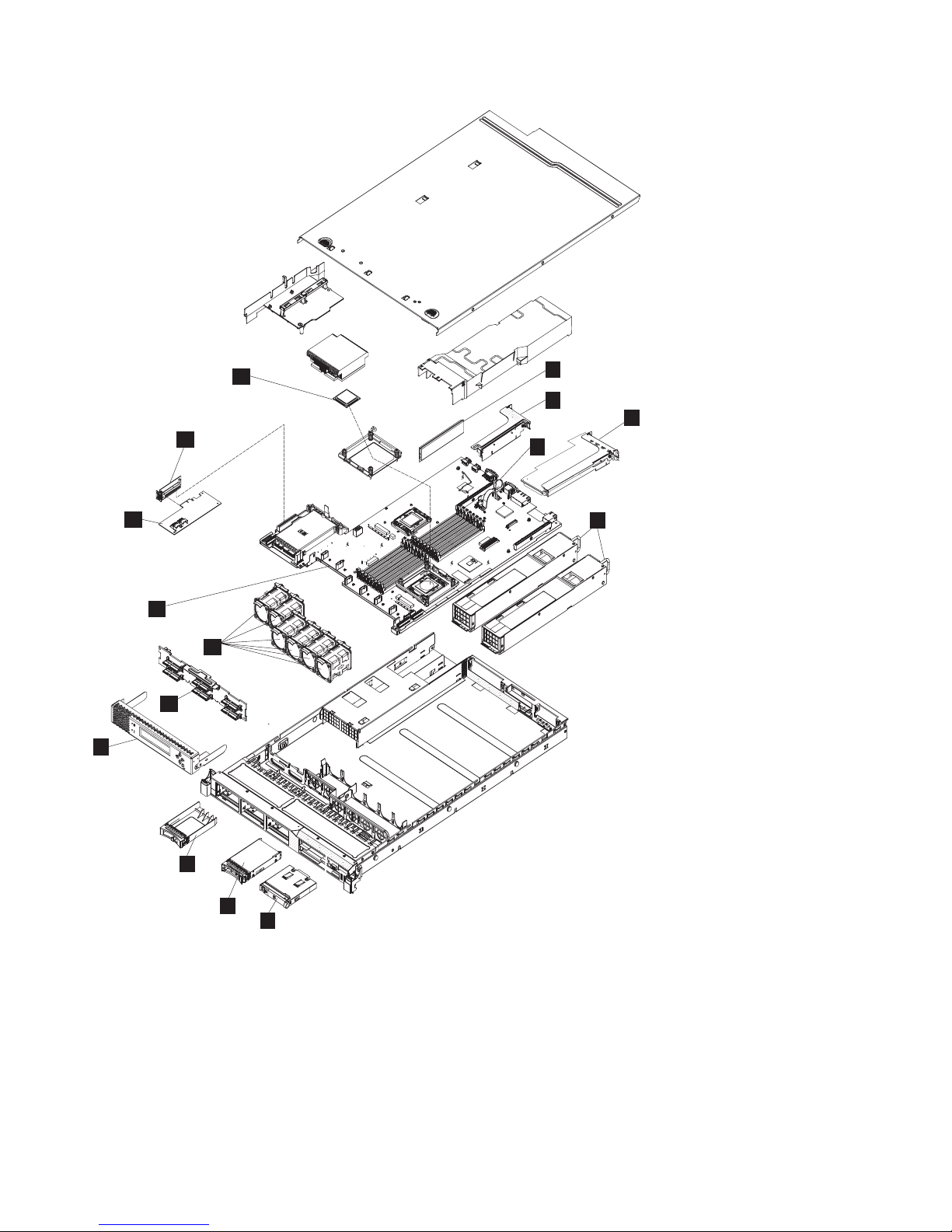
Figure 1 on page 2 shows how the different parts of the SAN Volume Controller 2145-CF8 are assembled.
© Copyright IBM Corp. 2003, 2010 1
Page 28
14
15
1
2
4
3
13
12
11
10
9
8
7
6
Figure 1. Exploded view of the SAN Volume Controller 2145-CF8 node
svc_nn1en026
5
The following tables identify part numbers and provide brief descriptions of the SAN Volume Controller
2145-CF8 parts. Use the assembly index number to locate and identify the parts that are shown in
Figure 1.
v Table 3 on page 3 calls out the FRUs that are referred to in service procedures.
v Table 4 on page 5 lists the FRUs that are not referred to by any SAN Volume Controller 2145-CF8
service procedure, but that might be replaced in some circumstances.
v “SAN Volume Controller 2145-CF8 parts” on page 1 lists the FRUs that are related to the optional
solid-state drive (SSD) features.
2 IBM SAN Volume Controller Hardware Maintenance Guide
Page 29
Table 3. FRUs in the SAN Volume Controller 2145-CF8 parts assembly
Assembly
index Part number Units Description
-1 44T1493 6 Memory module
4 GB memory module, DDR3-1333 2RX4 LP RDIMM
-2 31P1340 1 Optional: High speed SAS adapter
An assembly that includes a high speed SAS adapter card that
provides connectivity for up to four solid-state drives (SSDs), a
riser card, a blanking plate, and screws.
-3 33F8354 1 CMOS battery
3.0 volt battery on the system board that maintains power to back
up system BIOS settings.
-4 31P1337 1 4-port fibre-channel adapter
e
e
e
e
e
e
e
e
e
-5 39Y7201 2 Power supply unit
-6 44E4372 1 Operator-information panel
-7 42D0673 1 Disk drive
-8 44T2248 4 Drive bay blank EMC filler assembly
-9 31P1339 1 Service controller
-10 43V7071 1 Disk backplane
A fibre-channel host bus adapter (HBA) assembly that connects
the SVC CF8 to the fibre-channel fabric. It is located in PCI slot 1.
The adapter assembly includes the fibre-channel PCI Express
adapter, four short-wave small form-factor pluggable (SFP)
transceivers, the riser card, and the bracket.
Note: If the system is using alternative fibre-channel SFP
transceivers, replace the SFP transceivers on the FRU part with
the SFP transceivers from the fibre-channel adapter that is being
replaced.
Ac power supply, 675 Watt
This assembly includes the information panel that contains the
power-control button and diagnostics LEDs.
The serial-attached SCSI (SAS) 2.5 inch disk drive, which, when
ordered as a replacement, might be a supported compatible drive
of at least the same capacity as the one being replaced.
The service controller includes the front-panel display, buttons,
and associated electronics.
-11 43V6929 6 Fan assembly
-12 43V7072 1 System board
Hot-swap SAS 2.5” disk-drive backplane
The fan assembly is used in each of the six fan positions.
The system board is also called the planar.
Note: This part is the system board only. When replaced, you
must also have alcohol wipes and thermal grease.
Chapter 1. Parts listing 3
Page 30
Table 3. FRUs in the SAN Volume Controller 2145-CF8 parts assembly (continued)
Assembly
index Part number Units Description
-13 44E8690 1 Disk controller
SAS controller card for the SAS 2.5 inch disk drive that also
includes the riser card.
-14 44E8690 1 Disk controller / USB riser card
Riser card that connects the disk controller to the system board
and provides the USB port to which the service controller cable
connects.
-15 46D1266 1 Microprocessor
2.40 GHz Quad-core microprocessor
Note: This part is the microprocessor only. When replaced, you
must also have alcohol wipes and thermal grease.
- 31P1338 4 Short-wave SFP transceivers
1
1
1
1
1
1
1
1
- 31P1206 1 Service controller cable
- 43V6922 1 Disk signal cable
- 46C4148 1 Disk power cable
- 31P1294 1 Power cable assembly
- 49Y4817 1 Cable-management arm
- 46C4139 1 Operator information panel cable
Small form-factor pluggable (SFP) fibre-channel transceiver that
provides an auto-negotiating 2, 4, or 8 gigabits-per-second
short-wave optical connection on the 4-port fibre-channel adapter.
Note: It is possible that SFP transceivers other than those shipped
with the product are in use on the fibre-channel host bus adapter.
It is a customer responsibility to obtain replacement parts for such
SFP transceivers. The FRU part number is shown as “Non
standard - supplied by customer” in the vital product data.
The USB cable used to connect the service controller to the system
board.
200 mm SAS disk signal cable
SAS disk power cable
The cable assembly that connects the SAN Volume Controller and
the 2145 UPS-1U. The assembly consists of two power cables
bundled with a serial cable.
- 41Y9292 - Thermal grease
- 59P4739 - Alcohol wipe
4 IBM SAN Volume Controller Hardware Maintenance Guide
Cable that connects the operator information panel to the system
board
Grease that helps provide a thermal seal between the processor
and the heat sink
Cleaning wipe
Page 31

Table 4. FRUs to which SAN Volume Controller 2145-CF8 service procedures do not refer
Description Part number Quantity
Top cover 43V6933 1
Front panel moulding that surrounds the operator information panel 49Y4818 1
Air baffle kit (microprocessor and memory) 43V6931 1
Heat sink 49Y4820 1
Base chassis 49Y4813 1
Rail kit used to install the node in a rack 49Y4816 1
Cable management arm assembly 49Y4817 1
Cable retention bracket 31P1243 1
Front panel USB cable 43V6920 1
Front bezel assembly 49Y4818 1
DVD drive bay filler 49Y4824 1
240VA safety cover 49Y4823 1
HDD I2C signal cable 43V7023 1
e
Table 5. FRU parts for the long-wave small form-factor pluggable (SFP) transceiver feature
e
e
e
ee
Description
e
eee
e
Long-wave SFP transceiver FRU
Part
number
31P1345 1 to 4 5608
Quantity Feature Code
e
Long-wave SFP transceiver that provides an auto-negotiating 2, 4, or 8
e
gigabits-per-second 10 kilometer (km) long-wave optical connection on
e
the 4-port fibre-channel adapter.
e
Note: It is possible that SFP transceiver other than those shipped with
e
the product are in use on the fibre-channel host bus adapter. It is a
e
customer responsibility to obtain replacement parts for such SFP
e
transceiver. The FRU part number is shown as “Non standard - supplied
e
by customer” in the vital product data.
e
SAN Volume Controller 2145-8A4 parts
You might need to replace a SAN Volume Controller 2145-8A4 field replaceable unit (FRU).
Figure 2 on page 6 shows how the different parts of the SAN Volume Controller 2145-8A4 are assembled.
Chapter 1. Parts listing 5
Page 32

Figure 2. Exploded view of the SAN Volume Controller 2145-8A4 node
v Table 6 provides the part numbers and a brief description for parts that are exchanged within SAN
Volume Controller 2145-8A4 service procedures.
v Table 7 on page 8 provides the part numbers and a brief description for parts that are not exchanged
within SAN Volume Controller 2145-8A4 service procedures.
Use the assembly index number to locate and identify the parts that are shown in Figure 2.
Table 6. FRUs that are exchanged within SAN Volume Controller 2145-8A4 service procedures
Assembly index Part number Units Description
-2 41Y2854 4 Memory, 2 GB PC2-5300
-3 43W5112 1 Riser card, PCI Express
6 IBM SAN Volume Controller Hardware Maintenance Guide
ECC
Page 33

Table 6. FRUs that are exchanged within SAN Volume Controller 2145-8A4 service procedures (continued)
Assembly index Part number Units Description
-4 31P0937 1 4-port fibre-channel host
bus adapter
- 23R2770 4 Fibre-channel SFP
transceiver
-5 43W5103 1 System board (You need 1
alcohol wipe and 1 thermal
grease syringe when you
replace this FRU. If you do
not already have these,
order them before you
begin to replace the part.)
-6 39M4347 1 Disk cable assembly (A
SATA disk drive back plate
with 2 SATA cables)
-7 39Y7289 1 Power supply, 351 watt
-8 39M4322 5 Fan (40 mm)
-10 41Y8247 1 Hard disk drive, 3.5 in,
simple-swap SATA
This disk drive, when
ordered as a replacement,
will be a supported
compatible drive of at least
the same capacity as the
one being replaced.
-12 31P1157 1 Service controller, including
the front-panel display and
the display and control
buttons
-13 42C1513 1 Operator-information panel
- 39M6266 1 Operator-information panel
cable
-15 44X0204 1 Microprocessor, 3.0 GHz 6
MB dual core (You need 1
alcohol wipe and 1 thermal
grease syringe when you
replace this FRU. If you do
not already have these,
order them before you
begin to replace the part.)
- 33F8354 1 Battery, 3.0V
Chapter 1. Parts listing 7
Page 34

Table 6. FRUs that are exchanged within SAN Volume Controller 2145-8A4 service procedures (continued)
Assembly index Part number Units Description
- 31P1177 1 Power cable assembly
(SAN Volume Controller to
the 2145 UPS-1U).
The SAN Volume
Controller 2145-8A4 does
not work with previous
versions of the power cable
assembly. The correct
power cable assembly is
indicated by the red tape
that is used to bind the
cables together.
- 12R9914 1 External fibre-channel
cable, LC–LC, 5.0 m (16.4
ft)
- 12R9915 1 External fibre-channel
cable, LC–LC, 25.0 m (82 ft)
- 59P4739 1 Alcohol wipe
- 41Y9292 1 Thermal grease
Table 7. FRUs that are not exchanged within SAN Volume Controller 2145-8A4 service procedures
Assembly index Part number Quantity Description
- 32P9107 1 Support rail kit
- 31P1171 1 Cable retention bracket
- 43W5119 1 Chassis
1 42C1284 1 Top cover
9 42C1286 1 Drive cage
11 43W5115 1 Front bezel
14 39M6296 1 Air baffle
16 43W5117 1 Heat-sink assembly
retention module
17 43W5116 1 Heat-sink assembly
- 42C1282 1 3.5 in. SATA service label
- 43W5113 1 Service label
- 43W5114 1 CRU/FRU label
- 39M4351 2 Bracket ear
SAN Volume Controller 2145-8G4 parts
You might need to replace a SAN Volume Controller 2145-8G4 field replaceable unit (FRU).
Figure 3 on page 9 shows how the different parts of the SAN Volume Controller 2145-8G4 are assembled.
8 IBM SAN Volume Controller Hardware Maintenance Guide
Page 35

1
2
3
4
10
11
12
13
14
15
5
6
7
8
Figure 3. Exploded view of the SAN Volume Controller 2145-8G4 node
There are two versions of the SAN Volume Controller 2145-8G4 node: Rev 1 and Rev 2. The differences
between these two versions are in the memory and processor configuration. See Table 8 to determine
which version you have. In addition, the vital product data (VPD) for the node indicates the correct part
numbers for nodes that are working in a cluster.
Table 8. Distinctive characteristics of the SAN Volume Controller 2145-8G4 versions
Rev 1 version Rev 2 version
There is one label on the front of the node and it does
not include a revision number
9
svc00222
There are two labels on the front of the node; the larger
label is positioned on the optical drive filler panel and
includes the revision number
Chapter 1. Parts listing 9
Page 36

Table 8. Distinctive characteristics of the SAN Volume Controller 2145-8G4 versions (continued)
Rev 1 version Rev 2 version
Has two microprocessors Has one microprocessor
Has eight memory modules Has four memory modules
Has a serial number in the format mm-Fxxxx Has a serial number in the format mm-Gxxxx
The following tables identify part numbers and provide brief descriptions of the SAN Volume Controller
2145-8G4 parts. Use the assembly index number to locate and identify the parts that are shown in
Figure 3 on page 9.
v Table 9 lists the parts that are unique for the Rev 1 version.
v Table 10 lists the parts that are unique for the Rev 2 version.
v Table 11 lists the parts that are used with both versions.
v Table 12 on page 11 lists the FRUs that are not referred to by any SAN Volume Controller 2145-8G4
service procedure.
Table 9. FRU part numbers that are unique for the SAN Volume Controller 2145-8G4 Rev 1 version
Assembly index Part number Units Description
-2 42C4228 2 Microprocessor, 2.33 GHz
with heat sink
-3 39M5784 8 Memory, 1 GB ECC DRR2
Table 10. FRU part numbers that are unique for the SAN Volume Controller 2145-8G4 Rev 2 version
Assembly index Part number Units Description
-2 44R5646 1 Microprocessor, 2.5 GHz
(You need 1 alcohol wipe
and 1 thermal grease
syringe when you replace
this FRU. If you do not
already have these, order
them before you begin to
replace the part.)
-3 39M5790 4 Memory, 2 GB ECC DRR2
Table 11. FRUs in the SAN Volume Controller 2145-8G4 parts assembly
Assembly index Part number Units Description
-1 43W0609 1 Top cover
-4 31P0937 1 4-port fibre-channel host
bus adapter
-5 32R2883 1 Riser card, PCI Express
(Slot 1)
-6 31P1090 1 System board (You need 2
alcohol wipes and 2
thermal grease syringes
when you replace this FRU.
If you do not already have
these, order them before
you begin to replace the
part.)
-7 39Y7189 1 Power supply, 670 watt
10 IBM SAN Volume Controller Hardware Maintenance Guide
Page 37

Table 11. FRUs in the SAN Volume Controller 2145-8G4 parts assembly (continued)
Assembly index Part number Units Description
-8 and -15 26K8083 6 Fan assembly
- 33F8354 1 Battery, 3.0V
-9 43W0625 1 Operator-information panel
-10 31P0908 1 Service controller
-11 41Y8247 1 Hard disk drive, 3.5 in,
simple-swap SATA
(beginning with SAN
Volume Controller 4.3.1)
This disk drive, when
ordered as a replacement,
will be a supported
compatible drive of at least
the same capacity as the
one being replaced.
-12 32R2823 1 Simple-swap SATA disk
drive cage
-13 26K8060 1 Disk-drive backplane
-14 39Y6972 1 Power back plane
- 23R2770 1 Fibre-channel SFP
transceiver
- 31P1063 1 Power cable assembly
(SAN Volume Controller to
2145 UPS-1U)
- 39M5700 1 External fibre-channel
cable, LC–LC, 5.0 m (16.4
ft)
- 39M5701 1 External fibre-channel
cable, LC–LC, 25.0 m (82 ft)
- 59P4739 1 Alcohol wipe
- 41Y9292 1 Thermal grease
Table 12. FRUs that are not referenced by SAN Volume Controller 2145-8G4 service procedures
Part number Quantity Description
39Y9510 1 Kit, toolless rail
31P1045 1 Cable retainer assembly
26K8058 2 Front panel USB cable
32R2820 1 3.5 in. SATA service label
39Y9420 1 Air flow parts
39Y9423 2 Heat sink assembly
39Y9507 1 Media bezel assembly
43W0610 1 Service labels assembly
39Y9522 1 Main panel weldment
42C3983 1 Optical interposer card
43V4869 1 CRU/FRU label
Chapter 1. Parts listing 11
Page 38

Table 12. FRUs that are not referenced by SAN Volume Controller 2145-8G4 service procedures (continued)
Part number Quantity Description
39Y9507 1 Media bezel assembly
32R2823 1 3.5 in. SATA cartridge assembly
SAN Volume Controller 2145-8F4 parts
You might need to replace a SAN Volume Controller 2145-8F4 field replaceable unit (FRU).
Figure 4 shows how the different parts of the SAN Volume Controller 2145-8F4 are assembled.
1
2
3
4
14
13
5
6
7
8
9
11
12
10
Figure 4. Exploded view of the SAN Volume Controller 2145-8F4 node
svc00173
Table 13 provides the part numbers and a brief description of the frame assembly parts that are labeled in
Figure 4. The frame assembly comprises all the parts except the service controller and fibre-channel cards.
These parts are listed in Table 14 on page 13.
Table 13. SAN Volume Controller 2145-8F4 frame assembly
Assembly index Part number Units Description
31P0705 1 Frame assembly
12 IBM SAN Volume Controller Hardware Maintenance Guide
Page 39

Table 13. SAN Volume Controller 2145-8F4 frame assembly (continued)
Assembly index Part number Units Description
- 31P0769 1 80GB SATA HDD
This disk drive, when ordered as a replacement, will be a
supported compatible drive of at least the same capacity as the
one being replaced.
-1 23K4219 1 Top cover
-3 90P1956 1 Riser card, PCI Express
-4 39R9058 2 Heat sink
-5 13M8293 2 Microprocessor, 3.0 GHz
-6 90P5282 1 Heat sink retention module
- 90P5284 1 Chassis
- 23K4209 1 Cage assembly
-7 39Y6958 1 System board
-8 39Y7261 2 Voltage regulator module (VRM), 1U/75A
-9 39Y7169 1 Power supply, 585 watt
- 40K8157 1 Power backplane
- 33F8354 1 Battery, 3.0V
- 40K8160 1 Cable, fan power
- 40K8159 1 Cable, signal, front panel
-10 42C9719 1 Operator information panel
-11 40K8156 1 Fan holder with fan backplanes
-13 40K8139 3 Fan, 40×40×28
-14 40K8140 4 Fan, 40×40×56
- 73P2870 8 Memory, 1 GB ECC DRR2
Table 14. Items not included in the SAN Volume Controller 2145-8F4 frame assembly
Assembly index Part number Units Description
-2 31P0714 1 4-port fibre-channel host bus adapter
- 23R2770 1 Fibre-channel SFP transceiver
-12 31P0708 1 Service controller
- 23K4218 1 Kit, toolless rail
- 31P1063 1 Power cable assembly (SAN Volume Controller to the 2145
UPS-1U)
- 31P0715 1 Cable retainer
- 39M5699 External Fibre Channel cable, LC–LC, 1.0 m (3.3 ft)
- 39M5700 External Fibre Channel cable, LC–LC, 5.0 m (16.4 ft)
- 39M5701 External Fibre Channel cable, LC–LC, 25.0 m (82 ft)
- 12R9321 External Fibre Channel cable, LC–SC/LC, 1.0 m (3.3 ft)
SAN Volume Controller 2145-8F2 parts
You might need to replace a SAN Volume Controller 2145-8F2 field replaceable unit (FRU).
Chapter 1. Parts listing 13
Page 40

Figure 5 shows how the different parts for the SAN Volume Controller 2145-8F2 are assembled.
1
2
3
4
5
6
16
15
7
8
9
10
11
12
14
13
Figure 5. Exploded view of the SAN Volume Controller 2145-8F2 node
svc00109
Table 15 provides the part numbers and a brief description of the frame assembly parts that are labeled in
Figure 5. The frame assembly comprises all of the parts except the service controller and fibre-channel
cards. These parts are listed in Table 16 on page 15.
Table 15. SAN Volume Controller 2145-8F2 frame assembly
Assembly index Part number Units Description
64P7934 1 Frame assembly
-1 23K4219 1 Top cover
- 64P8332 1 80GB SATA HDD
-3 23K4211 1 Riser card, PCI (full height)
-4 90P1957 1 Riser card, PCI (low profile)
-6 90P5281 2 Heat sink
14 IBM SAN Volume Controller Hardware Maintenance Guide
Page 41

Table 15. SAN Volume Controller 2145-8F2 frame assembly (continued)
Assembly index Part number Units Description
-7 13M8293 2 Microprocessor, 3.0 GHz
-8 90P5282 1 Heat sink retention module
- 90P5284 1 Chassis
- 23K4209 1 Cage assembly
-9 32R1730 1 System board
-10 24R2698 2 VRM, 1U/75A
-11 24R2640 1 Power supply assembly
- 23K4515 1 Power backplane
- 33F8354 1 Battery, 3.0V
- 33P2352 1 Cable, fan power
- 25R4052 1 Cable, signal, front panel
-12 23K4992 1 Fan holder with fan
backplanes
-13 23K4490 1 Operator information panel
-15 23K4217 3 Fan, 40×40×28
-16 33P2335 4 Fan, 40×40×56
- 73P2870 8 Memory, 1 GB ECC DRR2
Table 16. Items not included in the SAN Volume Controller 2145-8F2 frame assembly
Assembly index Part number Units Description
-2 64P7783 1 Fibre-channel HBA (full
height)
-5 64P7813 1 Fibre-channel HBA (low
profile)
- 23R2770 1 Fibre-channel SFP
transceiver
-14 64P7874 1 Service controller
- 64P7940 1 Input power cable
assembly, (SAN Volume
Controller 2145-8F2 to the
2145 UPS-1U)
- 23K4218 1 Kit, toolless rail
- 39M5699 External fibre-channel
cable, LC–LC, 1.0 m (3.3 ft)
- 39M5700 External fibre-channel
cable, LC–LC, 5.0 m (16.4
ft)
- 39M5701 External fibre-channel
cable, LC–LC, 25.0 m (82 ft)
- 12R9321 External fibre-channel
cable, LC–SC/LC, 1.0 m
(3.3 ft)
Chapter 1. Parts listing 15
Page 42

Redundant ac-power switch parts
There is a single field-replaceable unit (FRU) assembly for the redundant ac power feature. It consists of
the switch and two input-power cables.
The redundant ac-power switch is an optional feature that makes the SAN Volume Controller nodes
resilient to the failure of a single power circuit. The redundant ac-power switch is not a replacement for
an uninterruptible power supply. You must still use a uninterruptible power supply for each node.
Figure 6 shows the redundant ac-power switch.
Table 17 lists the part numbers for the redundant ac-power switch.
svc00297
Figure 6. View of the redundant ac-power switch FRU
Table 17. Redundant ac-power switch
Part number Units Description
31P0896 1 Redundant ac-power switch assembly
2145 UPS-1U parts
The 2145 UPS-1U is assembled from four separate parts.
A 2145 UPS-1U powers one SAN Volume Controller node. Figure 7 on page 17 shows the parts that make
up the 2145 UPS-1U.
16 IBM SAN Volume Controller Hardware Maintenance Guide
Page 43

1
2
3
4
Figure 7. Exploded view of the 2145 UPS-1U hardware
Table 18 lists the different parts that are labeled in Figure 7.
Table 18. 2145 UPS-1U part numbers
Assembly
index Part number Units Description
31P1318 1 2145 UPS-1U assembly
Uninterruptible power supply assembly for use with 2145-CF8
31P0875 1 2145 UPS-1U assembly
Uninterruptible power supply assembly for use with 2145-8F2,
2145-8F4, 2145-8G4, and 2145-8A4.
The 31P1318 FRU part might be substituted for this FRU.
-1 Not available 1 Chassis assembly
5
svc00002
This item cannot be ordered and is supplied as part of the 2145
UPS-1U assembly.
-2 31P0710 1 Battery pack assembly
-3 Not available 1 Battery plate
This item cannot be ordered and is supplied as part of the 2145
UPS-1U assembly.
-4 31P0709 1 Front panel
-5 31P1060 1 2145 UPS-1U cable retention bracket kit
- 31P0711 1 Support rail kit, contains rails, nut clips, and screws
- 39M5376 1 Input-power cable, power distribution unit to the 2145 UPS-1U.
- 39M5116 1 Main power cable for the United States.
Power cables for the 2145 UPS-1U
If you do not connect the 2145 UPS-1U to a rack power-distribution unit (PDU) or redundant ac-power
switch, you must follow your country or region's power requirements to choose the appropriate power
cable for the 2145 UPS-1U.
The 2145 UPS-1U is supplied with an IEC 320-C13 to C14 jumper to connect it to a rack PDU. You can
also use this cable to connect the 2145 UPS-1U to the redundant ac-power switch.
Chapter 1. Parts listing 17
Page 44

The following table lists the power cable options for your country or region.
Connection type
(attached plug
designed for 200 -
Country or region Length
United States of America (Chicago), Canada,
Mexico
Bahamas, Barbados, Bermuda, Bolivia, Brazil,
Canada, Cayman Islands, Colombia, Costa
Rica, Dominican Republic, Ecuador, El
Salvador, Guatemala, Guyana, Haiti,
Honduras, Jamaica, Japan, Korea (South),
Liberia, Mexico, Netherlands Antilles,
Nicaragua, Panama, Peru, Philippines, Saudi
Arabia, Suriname, Taiwan, Trinidad (West
Indies), United States of America, Venezuela
Afghanistan, Algeria, Andorra, Angola,
Austria, Belgium, Benin, Bulgaria, Burkina
Faso, Burundi, Cameroon, Central African
Republic, Chad, Czech Republic, Egypt,
Finland, France, French Guiana, Germany,
Greece, Guinea, Hungary, Iceland, Indonesia,
Iran, Ivory Coast, Jordan, Lebanon,
Luxembourg, Macao S.A.R. of China,
Malagasy, Mali, Martinique, Mauritania,
Mauritius, Monaco, Morocco, Mozambique,
Netherlands, New Caledonia, Niger, Norway,
Poland, Portugal, Romania, Senegal, Slovakia,
Spain, Sudan, Sweden, Syria, Togo, Tunisia,
Turkey, former USSR, Vietnam, former
Yugoslavia, Zaire, Zimbabwe
Antigua, Bahrain, Brunei, Channel Islands,
Hong Kong S.A.R. of China, Cyprus, Dubai,
Fiji, Ghana, India, Iraq, Ireland, Kenya,
Kuwait, Malawi, Malaysia, Malta, Nepal,
Nigeria, Polynesia, Qatar, Sierra Leone,
Singapore, Tanzania, Uganda, United
Kingdom, Yemen, Zambia
Argentina 2.8 m (9 ft) IRAM 2073 39M5068
Argentina, Australia, New Zealand, Papua
New Guinea, Paraguay, Uruguay, Western
Samoa
Bangladesh, Burma, Pakistan, South Africa, Sri
Lanka
Chile, Ethiopia, Italy, Libya, Somalia 2.8 m (9 ft) CEI 23-16 39M5165
People's Republic of China 2.8 m (9 ft) GB 2099.1 39M5206
Denmark 2.8 m (9 ft) DK2-5a 39M5130
Israel 2.8 m (9 ft) SI 32 39M5172
Liechtenstein, Switzerland 2.8 m (9 ft) IEC 60884 Stnd. Sheet
Thailand 2.8 m (9 ft) NEMA 6-15P 39M5095
1.8 m (6 ft) NEMA L6-15P 39M5115
2.8 m (9 ft) NEMA L6-15P 39M5116
2.8 m (9 ft) CEE 7-VII 39M5123
2.8 m (9 ft) BS 1363/A 39M5151
2.8 m (9 ft) AS/NZS 3112/2000 39M5102
2.8 m (9 ft) SABS 164 39M5144
240 V ac input) Part number
39M5158
416534?2 (CH Type
12)
18 IBM SAN Volume Controller Hardware Maintenance Guide
Page 45

Chapter 2. Removing and replacing parts
You can remove and replace field-replaceable units (FRUs) from the SAN Volume Controller, redundant
ac-power switch, and uninterruptible power supply.
Each FRU has its own removal procedure. Sometimes you can find that a step within a procedure might
refer you to a different remove/replace procedure. You might want to complete the new procedure before
you continue with the first procedure that you started.
Remove or replace parts only when you are directed to do so by the IBM System Storage SAN Volume
Controller 2145 Troubleshooting Guide. Start all problem determination and repair procedures with MAP
5000.
Enabling concurrent maintenance
To allow concurrent maintenance, SAN Volume Controllers must be configured in pairs.
While one SAN Volume Controller is being serviced, the other keeps the I/O group operational. With
concurrent maintenance, all field-replaceable units (FRUs) can be removed, replaced, and tested on one
SAN Volume Controller while the SAN and host systems are powered on and doing productive work.
Attention: Do not remove the power from both SAN Volume Controllers unless the procedures instruct
you to do so.
Perform the following checks to verify that concurrent maintenance is enabled.
1. Confirm that no hosts have dependencies on the node.
When shutting down a node that is part of a cluster or when deleting the node from a cluster, you
can use either the management GUI or a command-line interface (CLI) command. In the management
GUI, click System Status. Click the correct node and click Manage to display all the volumes that are
dependent on a node. You can also use the node parameter with the svcinfo lsdependentvdisks CLI
command to view dependent volumes.
If dependent volumes exist, determine if the volumes are being used. If the volumes are being used,
either restore the redundant configuration or suspend the host application. If a dependent quorum
disk is reported, repair the access to the quorum disk or modify the quorum disk configuration.
2. Ensure that the host multipathing device drivers can fail over to the partner node.
Some host multipathing device drivers take a while to update after changes are made on the fabric.
Do not shut down a node or delete the node from a cluster if the partner node in the I/O group to
which the node belongs has not been online for more than 30 minutes.
If possible, check the status of the host multipathing device drivers before shutting down a node to
ensure that the device drivers can fail over to the partner node.
When shutting down the node, see MAP 5350 in the IBM System Storage SAN Volume Controller 2145
Troubleshooting Guide for a description of how to check for dependencies on the node during the
procedure to turn off the node.
When deleting a node from the cluster, see "Deleting a node from a cluster using the management GUI"
in the IBM System Storage SAN Volume Controller 2145 Troubleshooting Guide for a description of node
information to retain to avoid data corruption when adding the node back to the cluster, how to ensure
that the multipathing device driver does not rediscover any paths that are manually removed, and for
other considerations regarding dependent volumes.
© Copyright IBM Corp. 2003, 2010 19
Page 46

For more information about working with dependent volumes, see the following topics:
v "Listing node-dependent VDisks (volumes) using the CLI" in the IBM System Storage SAN Volume
Controller 2145 Troubleshooting Guide
v "lsnodedependentvdisks" command description in the IBM System Storage SAN Volume Controller
Command-Line Interface User's Guide
Preparing to remove and replace parts
Before you remove and replace parts, you must be aware of all safety issues.
First, read the safety precautions in the IBM Systems Safety Notices. These guidelines help you safely work
with the SAN Volume Controller, redundant ac-power switch, and uninterruptible power supply.
Working inside the node with the power on
When you are servicing the SAN Volume Controller node, you might need to turn on the node while the
cover is off.
Attention: Static electricity that is released to internal components when the node is turned on might
cause the node to halt, which might result in the loss of data. To avoid this potential problem, always use
an electrostatic-discharge wrist strap or other grounding system when you work inside the node with the
power on.
You might be instructed to turn on the node and look at system-board LEDs while the cover is off.
Follow these guidelines when you work inside a node that is turned on:
v Avoid wearing loose-fitting clothing on your forearms. Button long-sleeved shirts before working
inside the server; do not wear cuff links while you are working inside the node.
v Do not allow your necktie or scarf to hang inside the node.
v Remove jewelry, such as bracelets, necklaces, rings, and loose-fitting wrist watches.
v Remove items from your shirt pocket, such as pens and pencils, that could fall into the node as you
lean over it.
v Avoid dropping any metallic objects, such as paper clips, hairpins, and screws, into the node.
Removing and replacing SAN Volume Controller parts
The remove and replace procedures for the SAN Volume Controller field replaceable units are described
in the topics that follow.
Removing the cable-management arm
You can remove the SAN Volume Controller 2145-CF8 cable-management arm from the rack.
Removing the SAN Volume Controller 2145-CF8 cable-management arm
Remove the SAN Volume Controller 2145-CF8 cable-management arm that routes and secures the power
cables and other cables.
The parts involved in removing the cable-management arm are shown in Figure 8 on page 21.
20 IBM SAN Volume Controller Hardware Maintenance Guide
Page 47

10
9
8
6
1
2
3
4
5
7
Figure 8. SAN Volume Controller 2145-CF8 cable-management arm, support rails, and associated parts
Table 19. Cable-management arm and associated parts descriptions and quantities
Reference Description Quantity
1 Slide rail (left) 1
2 Slide rail (right) 1
3 Large cable tie 1
4 Cable ties 5
5 M6 screws 4
6 10-32 screws 2
7 Cable-management support arm 1
8 Cable-management arm mounting bracket 1
9 Cable-management arm stop bracket 1
10 Cable-management arm assembly 1
svc_bb1ka200
The cable-management arm is installed to pivot from the left side of the SAN Volume Controller
2145-CF8 rack.
To remove the cable-management arm, perform the following steps:
1. Remove all power from the node, as described in MAP 5350 in the IBM System Storage SAN Volume
Controller 2145 Troubleshooting Guide.
2. Disconnect all cables from the back of the SAN Volume Controller 2145-CF8 node.
3. Slide the SAN Volume Controller 2145-CF8 away from the back of the rack.
a. Remove any optional M6 screws, as shown by 1 in Figure 9 on page 22, from the front of the
node.
b. To release the node from the rack, press the orange release latches 2 and slide the SAN Volume
Controller 2145-CF8 node forward until it latches in the service position.
Chapter 2. Removing and replacing parts 21
Page 48

1
2
svc_bb1ka051
Figure 9. SAN Volume Controller 2145-CF8 release latches and mounting screws
4. Disconnect the power cords and other cables from the cable-management arm.
a. Remove the cable ties or hook-and-loop fasteners.
b. Free the cables and power cords from the cable-management arm, as shown by 1 in Figure 10.
1
Figure 10. SAN Volume Controller 2145-CF8 cables in the cable-management arm
5. Remove the cable-management arm from the support arm.
a. Pull out the cable-management arm pin, as shown by 3 in Figure 11 on page 23, then slide the
cable-management arm tab out of the slot 4 on the outside of the slide rail.
b. Pull the tab until it is free.
c. Pull out the other cable-management arm pin 1, then slide the cable-management arm tab 2
out of the slot on the inside of the slide rail.
d. Pull the tab until it is free.
22 IBM SAN Volume Controller Hardware Maintenance Guide
svc00547
Page 49

4
2
3
1
svc_bb1ka225
Figure 11. SAN Volume Controller 2145-CF8 cable-management arm on the support arm
6. Remove the cable-management mounting bracket from the same slide rail onto which the
cable-management arm was installed.
The cable-management support arm is not shown in Figure 12 on page 24.
Pull out the mounting bracket pin 1 and slide the mounting bracket 2 out of the left slide rail.
Pull the bracket from the slide rail until it is free.
Chapter 2. Removing and replacing parts 23
Page 50

2
1
svc_bb1ka041
Figure 12. Removing the SAN Volume Controller 2145-CF8 cable-management arm mounting bracket
7. To free the swing end of the support arm from the backside of the slide rail, push the blue latch on
the cable-support-arm stop bracket on the right rail to open the cable-management arm, pivoting the
arm on the left rail, as shown by 1 in Figure 13, and then slide the bracket 2 from the slide rail.
2
1
svc_bb1ka036
Figure 13. Freeing the swing end of the SAN Volume Controller 2145-CF8 support arm
8. Remove the L-shaped cable-management stop bracket on the unattached end of the support arm. Turn
the bracket, as shown by 1 in Figure 14 on page 25 to free it from the support arm. Then lift the
cable-management stop bracket 2 from the support arm.
24 IBM SAN Volume Controller Hardware Maintenance Guide
Page 51

1
2
svc_bb1ka031
Figure 14. Removing the SAN Volume Controller 2145-CF8 cable-management stop bracket
9. Disconnect the attached end of the support arm, as shown by 1 in Figure 15, from the same slide
rail from which you detached the cable-management arm.
2
1
svc_bb1ka026
Figure 15. Detaching the SAN Volume Controller 2145-CF8 cable-management support arm
Replacing the cable-management arm
Replace the cable-management arm after you install the SAN Volume Controller 2145-CF8 node into the
rack.
Replacing the SAN Volume Controller 2145-CF8 cable-management arm
The SAN Volume Controller 2145-CF8 uses a cable-management arm to route and secure power cables
and other cables.
Replace the SAN Volume Controller 2145-CF8 cable-management arm after you replace the node in the
rack.
The cable-management arm is installed to pivot from the left side of the SAN Volume Controller
2145-CF8 rack, when viewed from the rear of the rack.
To attach the cable-management arm, perform the following steps:
1. At the rear of the rack, connect one end of the support arm, as shown by 1 in Figure 16 on page 26,
to the same slide rail to which you plan to attach the cable-management arm so that you can swing
the other end of the support arm 2 toward the rack.
Chapter 2. Removing and replacing parts 25
Page 52

2
2
1
svc_bb1ka025
Figure 16. Rack rear: Attaching the SAN Volume Controller 2145-CF8 cable-management support arm
2. Install the L-shaped cable-management stop bracket, as shown by 1 in Figure 17 on the unattached
end of the support arm. Turn the bracket 2 to secure it to the support arm.
2
1
svc_bb1ka030
Figure 17. Rack rear: Installing the SAN Volume Controller 2145-CF8 cable-management stop bracket
3. To attach the other side of the support arm to the backside of the slide rail, push the blue latch on the
cable-support-arm stop bracket, as shown by 1 in Figure 18, to slide the bracket 2 into the slide
rail.
2
1
svc_bb1ka035
Figure 18. Attaching the free end of the SAN Volume Controller 2145-CF8 support arm
26 IBM SAN Volume Controller Hardware Maintenance Guide
Page 53

4. To install the cable-management arm assembly, you must place the cable-management arm mounting
bracket into the same slide rail onto which you installed the cable-management support arm.
The cable-management support arm is not shown in Figure 19.
Push the blue latch on the cable-support-arm stop bracket 1 to slide the mounting bracket 2 into
the left slide rail. Push the bracket into the slide rail until the bracket snaps into place.
2
1
Figure 19. Rack rear: Installing the SAN Volume Controller 2145-CF8 cable-management arm mounting bracket
svc_bb1ka040
5. Place the cable-management arm on the support arm.
a. Pull out the cable-management arm pin, as shown by 1 in Figure 20 on page 28, then slide the
cable-management arm tab 2 into the slot on the inside of the slide rail.
b. Push the tab until it snaps into place.
c. Pull out the other cable-management arm pin 3, then slide the cable-management arm tab into
the slot 4 on the outside of the slide rail.
d. Push the tab until it snaps into place.
Chapter 2. Removing and replacing parts 27
Page 54

4
2
3
1
svc_bb1ka225
Figure 20. SAN Volume Controller 2145-CF8 cable-management arm on the support arm
6. Attach the power cords and data cables to the rear of the node.
a. Route the cables and power cords on the cable-management arm, as shown by 1 in Figure 21 on
page 29.
If you attach the arm properly and route the cables properly, the arm swings into the rack as you
pull the node forward in the rack, opening to allow the cables to follow the node toward the front
of the rack. You can perform some service procedures from the fully extended rail position
without disconnecting the fibre-channel cables and the Ethernet cables. You can also perform some
service procedures without turning off the node or disconnecting the power cables.
b. Secure the cables with cable ties or hook-and-loop fasteners.
Note: Leave some slack in all of the cables to avoid tension in the cables as the cable-management
arm moves.
28 IBM SAN Volume Controller Hardware Maintenance Guide
Page 55

1
svc00547
Figure 21. SAN Volume Controller 2145-CF8 cables in the cable-management arm
7. Slide the SAN Volume Controller 2145-CF8 into the rack until it snaps into place.
8. Connect all cables to the back of the SAN Volume Controller 2145-CF8 node.
Removing the cable-retention bracket
The SAN Volume Controller models 2145-CF8, 2145-8A4, 2145-8G4, 2145-8F4, and 2145-8F2 provide a
cable-retention bracket, which ensures that the node does not mistakenly become unplugged from the
uninterruptible power supply.
Removing the SAN Volume Controller 2145-CF8 cable-retention brackets
You can remove the two SAN Volume Controller 2145-CF8 cable-retention brackets when removing the
power cords from the node.
DANGER
Multiple power cords. The product might be equipped with multiple power cords. To remove all
hazardous voltages, disconnect all power cords.
The SAN Volume Controller 2145-CF8 uses two toolless cable-retention brackets, one to retain each cable
from the uninterruptible power-supply to one of the two SAN Volume Controller 2145-CF8 power
supplies, as shown in Figure 22 on page 30.
Chapter 2. Removing and replacing parts 29
Page 56

2
1
Figure 22. SAN Volume Controller 2145-CF8 cable-retention brackets
Each cable-retention bracket attaches to the back of the SAN Volume Controller 2145-CF8 node. The
brackets connect without screws.
This service action requires you to:
v Optionally, turn off the node.
v Disconnect the power cable that the retention bracket is on.
To remove a cable-retention bracket, perform these steps:
1. Read the safety information to which “Preparing to remove and replace parts” on page 20 refers.
2. Optional: Follow the procedure in MAP 5350 in the IBM System Storage SAN Volume Controller 2145
Troubleshooting Guide to verify that the node data is mirrored and synchronized, and that there are no
dependent volumes before turning off the node.
Important: If you decide to hot swap a power supply, and that is why you are removing the cable
retention bracket, use MAP 5350 to make all of the necessary checks that ensure that the partner node
in the I/O group can take over all I/O group operations, if necessary, and that there are no dependent
VDisks on the node. With the partner node available and no dependent VDisks on the node, you do
not lose access to data if this node accidentally powers off.
3. Pull back the cable-management arm if you are working from the rear of the rack, or slide the node
out of the rack to the fully extended rail position if you are working from the front.
4. When the node is completely turned off, from under the cable, carefully push the spring clip away
from the cable to free the cable-retention bracket from the handle on the power supply.
The spring clip is shown by 1 in Figure 22.
5. Pull both the bracket and the cable (2) away from the SAN Volume Controller 2145-CF8 power
supply.
6. Remove the cable-retention bracket from the power cord.
Removing the SAN Volume Controller 2145-8A4 cable retention bracket
The cable-retention bracket attaches to the back of the SAN Volume Controller 2145-8A4 node. It is
connected with one screw that already holds the rear plate of the power supply in place.
Remove the cable-retention bracket before you remove the SAN Volume Controller 2145-8A4 node from
the rack.
To remove the bracket from the node, perform the following steps:
30 IBM SAN Volume Controller Hardware Maintenance Guide
Page 57

1. With the node turned off, unscrew the retaining screw1, shown in Figure 23, half a turn, but do not
fully loosen or remove it.
1
svc00475
Figure 23. SAN Volume Controller 2145-8A4 with the cable-retention bracket installed
2. Slide the bracket to the right just enough to disengage the screw.
3. Squeeze the top and bottom of the bracket together slightly and turn the bracket at a slight angle to
remove both lips of the bracket from the node frame.
4. Slide the bracket back onto the power cable and then slide it off the cable.
5. Remove the power cable.
Removing the SAN Volume Controller 2145-8G4 cable retention bracket
The SAN Volume Controller 2145-8G4 uses one of two different cable-retention brackets. Depending on
which bracket you have, use the appropriate instructions to remove and replace the cable-retention
bracket.
v If your cable-retention bracket looks like the bracket in Figure 24 on page 32, go to “Removing the
SAN Volume Controller 2145-8G4 cable retention bracket - option A” on page 32.
Chapter 2. Removing and replacing parts 31
Page 58

svc00363
Figure 24. SAN Volume Controller 2145-8G4 cable retention bracket - type A
v If your cable-retention bracket looks like the bracket in Figure 25, go to “Removing the SAN Volume
Controller 2145-8G4 cable retention bracket - option B” on page 33.
svc00362
Figure 25. SAN Volume Controller 2145-8G4 cable retention bracket - type B
Removing the SAN Volume Controller 2145-8G4 cable retention bracket - option A:
The cable-retention bracket attaches to the back of the SAN Volume Controller 2145-8G4 node. It is
connected with the screws that already hold the rear plate of the power supply in place.
Remove the cable-retention bracket before you remove the SAN Volume Controller 2145-8G4 node from
the rack.
32 IBM SAN Volume Controller Hardware Maintenance Guide
Page 59

To remove the cable-retention bracket, perform these steps:
1. Carefully remove the two retaining screws on the right side of the power supply rear plate shown in
Figure 26.
svc00365
Figure 26. The SAN Volume Controller 2145-8G4 with the cable-retention bracket attached
2. Remove the bracket.
3. Replace the screws in the power supply rear plate.
Removing the SAN Volume Controller 2145-8G4 cable retention bracket - option B:
Remove the cable-retention bracket before you remove the SAN Volume Controller 2145-8G4 from the
rack.
To remove the cable-retention bracket, perform these steps:
1. Remove the securing bolt from the node side rail (shown in Figure 27 on page 34) next to the power
supply.
Chapter 2. Removing and replacing parts 33
Page 60

svc00302
Figure 27. The SAN Volume Controller 2145-8G4 with cable-retention bracket type B attached
2. Remove the bracket.
3. Replace the bolt in the node side rail.
Removing the SAN Volume Controller 2145-8F4 cable retention bracket
The cable-retention bracket attaches to the back of the SAN Volume Controller 2145-8F4 node. It is
connected with one screw that already holds the rear plate of the power supply in place.
Remove the cable-retention bracket before you remove the SAN Volume Controller 2145-8F4 node from
the rack.
To remove the bracket from the node, perform the following steps:
1. With the node turned off, pull the cable-retention bracket backward slightly to disengage the bracket
from the slot at the rear of the support rail.
2. Slide the bracket out of the support rail and then move it to the right away from the cable.
3. Remove the power cable.
Replacing the cable-retention bracket
Replace the cable-retention bracket after you install SAN Volume Controller model 2145-8A4, 2145-8G4,
or 2145-8F4 into the rack.
Replacing the SAN Volume Controller 2145-CF8 cable-retention brackets
Replace one of the two cable-retention brackets on the back of the SAN Volume Controller 2145-CF8 to
anchor the power cord that runs from the uninterruptible power-supply to one of the two SAN Volume
Controller 2145-CF8 power supplies.
DANGER
Multiple power cords. The product might be equipped with multiple power cords. To remove all
hazardous voltages, disconnect all power cords.
The SAN Volume Controller 2145-CF8 uses two toolless cable-retention brackets, one to retain each cable
from the uninterruptible power-supply to one of the two SAN Volume Controller 2145-CF8 power
supplies, as shown in Figure 28 on page 35.
34 IBM SAN Volume Controller Hardware Maintenance Guide
Page 61

2
1
Figure 28. SAN Volume Controller 2145-CF8 cable-retention brackets
Each cable-retention bracket attaches to the back of the SAN Volume Controller 2145-CF8 node. The
brackets connect without screws.
To replace each cable-retention bracket, perform these steps:
1. If you removed the node from the rack, replace the node in the rack, as described in “Replacing the
SAN Volume Controller in a rack” on page 48.
2. If you removed any fibre-channel or Ethernet cables, use the labels you placed on each cable to
replace all fibre-channel and Ethernet cables in the same ports from which they were removed.
3. Loosely install the cable-retention bracket on a power cord by slipping the power cord into the notch
on the rear of the bracket.
4. Align the cable-retention bracket on the power cord so that the bracket is to the left of the cord, as
shown by 2 in Figure 28.
5. Align the power cord with the power connector on the power supply and the bracket with the
power-supply handle.
6. Push the power cord into the power connector on the power supply.
7. Carefully push the bracket against the power-supply handle to force the spring clip (1) over the
leading edge of the handle.
8. Lift the locking levers (1 in Figure 29 on page 36) on the slide rails and push the server 2 all the
way into the rack until it clicks into place.
Chapter 2. Removing and replacing parts 35
Page 62

svc_bb1ka055
Figure 29. Raising the SAN Volume Controller 2145-CF8 locking levers of the slide rails of the rack
9. Turn on the node.
Replacing the SAN Volume Controller 2145-8A4 cable retention bracket
The cable-retention bracket attaches to the back of the SAN Volume Controller 2145-8A4 node. It is
connected to the back of the node with the screw that already holds the rear plate of the power supply in
place.
To attach the bracket, perform the following steps:
1. Insert the power cable in the node.
2. Unscrew the retaining screw 1 that is located next to the power cable socket three full turns, but do
not fully remove the screw, as shown in Figure 30.
Figure 30. Retaining screw on the SAN Volume Controller 2145-8A4 node
3. Slide the bracket jaw over the power cable.
4. Slide the bracket down the cable until it is next to the power plug and slightly to the right of where it
needs to be.
5. Place the bottom lip of the retention bracket in the node chassis as shown in Figure 31 on page 37.
Turn the bracket at a slight angle, squeeze the top and bottom together, and position the top lip in
36 IBM SAN Volume Controller Hardware Maintenance Guide
1
svc00480
Page 63

place behind the chassis back plate.
svc00477
Figure 31. Installing the SAN Volume Controller 2145-8A4 cable retention bracket
6. Slide the bracket to the left until the side lip of the retention bracket goes behind the screw. Tighten
the screw.
Replacing the SAN Volume Controller 2145-8G4 cable retention bracket
The SAN Volume Controller 2145-8G4 uses one of two different cable-retention brackets. Depending on
which bracket you have, use the appropriate instructions to remove and replace the cable-retention
bracket.
v If your cable-retention bracket looks like the following, go to “Replacing the cable-retention bracket -
option A” on page 38.
Chapter 2. Removing and replacing parts 37
Page 64

svc00363
Figure 32. SAN Volume Controller 2145-8G4 cable retention bracket - type A
v If your cable-retention bracket looks like the following, go to “Replacing the cable-retention bracket -
option B” on page 39.
svc00362
Figure 33. SAN Volume Controller 2145-8G4 cable retention bracket - type B
Replacing the cable-retention bracket - option A:
The cable-retention bracket attaches to the back of the SAN Volume Controller 2145-8G4 node. It is
connected with the screws that already hold the rear plate of the power supply in place.
Replace the SAN Volume Controller 2145-8G4 cable retention bracket after you replace the node in the
rack.
38 IBM SAN Volume Controller Hardware Maintenance Guide
Page 65

To attach the bracket to the rack rail, perform the following steps:
1. With the node powered off and the power cable removed, loosen and remove the two screws
the right side of the rear plate that covers the power supply fan unit, as shown in Figure 34.
1
svc00364
1
on
Figure 34. The SAN Volume Controller 2145-8G4 before you attach the cable-retention bracket
2. Rotate the power supply handle out of the way.
3. Insert the power cable.
4. Position the cable-retention bracket so that the power cable runs through the slot in the bracket. Align
the screw holes in the bracket with the holes that are in the rear plate where you removed the two
screws.
5. Replace the top screw.
6. Move the power supply handle back into place over the retention bracket, and replace the lower
screw so that it holds the power supply handle, cable-retention bracket, and power supply rear plate
in place.
Replacing the cable-retention bracket - option B:
Replace the SAN Volume Controller 2145-8G4 cable retention bracket after you replace the node in the
rack.
Install the SAN Volume Controller 2145-8G4 cable retention bracket after you install the node in the rack.
To attach the bracket to the rack rail, perform the following steps:
1. Install the power cable into the power supply.
2. At the back of the cabinet, remove the securing bolt from the node side rail next to the power supply,
as shown in Figure 35 on page 40.
Chapter 2. Removing and replacing parts 39
Page 66

svc00302
Figure 35. The SAN Volume Controller 2145-8G4 with cable-retention bracket type B attached
3. Slide the cable-retention bracket over the cable and position it over the side rail. Secure it in place
using the original bolt.
Replacing the SAN Volume Controller 2145-8F4 cable retention bracket
The cable-retention bracket attaches to the support rail at the back of the SAN Volume Controller
2145-8F4 node.
To attach the bracket, perform the following steps:
1. Insert the power cable in the node.
2. Insert the bracket onto the power cable so that the power cable is held by the slot on the end of the
bracket. Figure 36 provides a view of how to align the cable-retention bracket with the cable.
Figure 36. Attaching the cable retention bracket to the SAN Volume Controller 2145-8F4 power cable
3. Position the cable-retention bracket against the support rail and attach the bracket onto the slot in the
rear of the rail.
Removing the SAN Volume Controller from a rack
During some service procedures, you might need to remove the SAN Volume Controller from a rack.
40 IBM SAN Volume Controller Hardware Maintenance Guide
svc00175
Page 67

Turning off the SAN Volume Controller node
When instructed to do so, shut down and turn off the SAN Volume Controller node before you remove
and replace parts.
For information about how to turn off the SAN Volume Controller and retain access to its data, see MAP
5350 in the IBM System Storage SAN Volume Controller 2145 Troubleshooting Guide.
Attention: Unless host systems or fibre-channel switches must be switched off for another reason, do
not turn them off when you are servicing the SAN Volume Controller. Shut down the SAN Volume
Controller before you remove the power cables. You can connect or disconnect Ethernet and fibre-channel
cables at any time.
Removing the SAN Volume Controller 2145-CF8 from a rack
Use these instructions when you are prompted to remove a SAN Volume Controller 2145-CF8 from a
rack.
DANGER
Multiple power cords. The product might be equipped with multiple power cords. To remove all
hazardous voltages, disconnect all power cords.
Attention: Do not touch the power control switches on adjacent SAN Volume Controller nodes when
you remove or install SAN Volume Controller nodes in a rack. Touching these switches on adjacent SAN
Volume Controller nodes might cause those devices to turn off and make customer data inaccessible.
Use the reference numbers in parentheses at the end of each notice, such as (C003) for example, to find
the matching translated notice in IBM Systems Safety Notices.
Chapter 2. Removing and replacing parts 41
Page 68

DANGER
Observe the following precautions when working on or around your IT rack system:
v Heavy equipment–personal injury or equipment damage might result if mishandled.
v Always lower the leveling pads on the rack cabinet.
v Always install stabilizer brackets on the rack cabinet.
v To avoid hazardous conditions due to uneven mechanical loading, always install the heaviest
devices in the bottom of the rack cabinet. Always install servers and optional devices starting
from the bottom of the rack cabinet.
v Rack-mounted devices are not to be used as shelves or work spaces. Do not place objects on top
of rack-mounted devices.
v Each rack cabinet might have more than one power cord. Be sure to disconnect all power cords in
the rack cabinet when directed to disconnect power during servicing.
v Connect all devices installed in a rack cabinet to power devices installed in the same rack
cabinet. Do not plug a power cord from a device installed in one rack cabinet into a power
device installed in a different rack cabinet.
v An electrical outlet that is not correctly wired could place hazardous voltage on the metal parts of
the system or the devices that attach to the system. It is the responsibility of the customer to
ensure that the outlet is correctly wired and grounded to prevent an electrical shock.
(R001 part 1 of 2)
DANGER
v Do not install a unit in a rack where the internal rack ambient temperatures will exceed the
manufacturer's recommended ambient temperature for all your rack-mounted devices.
v Do not install a unit in a rack where the air flow is compromised. Ensure that air flow is not
blocked or reduced on any side, front, or back of a unit used for air flow through the unit.
v Consideration should be given to the connection of the equipment to the supply circuit so that
overloading of the circuits does not compromise the supply wiring or overcurrent protection. To
provide the correct power connection to a rack, refer to the rating labels located on the
equipment in the rack to determine the total power requirement of the supply circuit.
v (For sliding drawers) Do not pull out or install any drawer or feature if the rack stabilizer
brackets are not attached to the rack. Do not pull out more than one drawer at a time. The rack
might become unstable if you pull out more than one drawer at a time.
v (For fixed drawers) This drawer is a fixed drawer and must not be moved for servicing unless
specified by the manufacturer. Attempting to move the drawer partially or completely out of the
rack might cause the rack to become unstable or cause the drawer to fall out of the rack.
(R001 part 2 of 2)
Important:
You can perform most service actions when the node is fully extended from the rack on its slide rails.
42 IBM SAN Volume Controller Hardware Maintenance Guide
Page 69

To remove the SAN Volume Controller 2145-CF8 from the rack, complete these steps:
1. Follow the procedure in MAP 5350 in the IBM System Storage SAN Volume Controller 2145
Troubleshooting Guide to verify that the node data is mirrored and synchronized, and that there are no
dependent volumes before turning off the node..
2. Pull back the cable-management arm if you are working from the rear of the rack, or slide the node
out of the rack to the fully extended rail position if you are working from the front.
3. To make sure that you can replace all cables in the same ports from which they were removed, record
the position of all fibre-channel and Ethernet cables; then remove all cables from the back of the node.
4. Pull forward the two white catches (1 in Figure 37) on the side of the rails, and lift up the front of
the node very slightly.
5. Support the node from the front and the back and pull the node forward slightly and lift to remove
the node from the back of the rails (3).
svc_bb1ka060
Figure 37. Removing the SAN Volume Controller 2145-CF8 from the rack
Removing the SAN Volume Controller 2145-8A4 from a rack
Use these instructions when you are prompted to remove a SAN Volume Controller 2145-8A4 from a
rack.
If the SAN Volume Controller is not already turned off, see "Turning off the SAN Volume Controller
node" in the IBM System Storage SAN Volume Controller 2145 Troubleshooting Guide .
Attention: Do not touch the power control switches on adjacent SAN Volume Controller nodes when
you remove or install SAN Volume Controller nodes in a rack. Touching these switches on adjacent SAN
Volume Controller nodes might cause those devices to turn off and make customer data inaccessible.
Use the reference numbers in parentheses at the end of each notice, such as (C003) for example, to find
the matching translated notice in IBM Systems Safety Notices.
Chapter 2. Removing and replacing parts 43
Page 70

DANGER
Observe the following precautions when working on or around your IT rack system:
v Heavy equipment–personal injury or equipment damage might result if mishandled.
v Always lower the leveling pads on the rack cabinet.
v Always install stabilizer brackets on the rack cabinet.
v To avoid hazardous conditions due to uneven mechanical loading, always install the heaviest
devices in the bottom of the rack cabinet. Always install servers and optional devices starting
from the bottom of the rack cabinet.
v Rack-mounted devices are not to be used as shelves or work spaces. Do not place objects on top
of rack-mounted devices.
v Each rack cabinet might have more than one power cord. Be sure to disconnect all power cords in
the rack cabinet when directed to disconnect power during servicing.
v Connect all devices installed in a rack cabinet to power devices installed in the same rack
cabinet. Do not plug a power cord from a device installed in one rack cabinet into a power
device installed in a different rack cabinet.
v An electrical outlet that is not correctly wired could place hazardous voltage on the metal parts of
the system or the devices that attach to the system. It is the responsibility of the customer to
ensure that the outlet is correctly wired and grounded to prevent an electrical shock.
(R001 part 1 of 2)
DANGER
v Do not install a unit in a rack where the internal rack ambient temperatures will exceed the
manufacturer's recommended ambient temperature for all your rack-mounted devices.
v Do not install a unit in a rack where the air flow is compromised. Ensure that air flow is not
blocked or reduced on any side, front, or back of a unit used for air flow through the unit.
v Consideration should be given to the connection of the equipment to the supply circuit so that
overloading of the circuits does not compromise the supply wiring or overcurrent protection. To
provide the correct power connection to a rack, refer to the rating labels located on the
equipment in the rack to determine the total power requirement of the supply circuit.
v (For sliding drawers) Do not pull out or install any drawer or feature if the rack stabilizer
brackets are not attached to the rack. Do not pull out more than one drawer at a time. The rack
might become unstable if you pull out more than one drawer at a time.
v (For fixed drawers) This drawer is a fixed drawer and must not be moved for servicing unless
specified by the manufacturer. Attempting to move the drawer partially or completely out of the
rack might cause the rack to become unstable or cause the drawer to fall out of the rack.
(R001 part 2 of 2)
To remove the SAN Volume Controller 2145-8A4 from a rack, complete these steps:
1. Remove the cable-retention bracket and disconnect the power cable from the node. See “Removing the
cable-retention bracket” on page 29.
44 IBM SAN Volume Controller Hardware Maintenance Guide
Page 71

2. To make sure that you can replace all cables in the same ports from which they were removed, record
the position of all fibre-channel and Ethernet cables; then remove all cables from the back of the node.
1
3. Loosen the captive thumbscrews (
in Figure 38) that secure the node to the front mounting flanges.
Figure 38. The captive thumbscrews that secure the node and the shipping brackets
4. Pull the SAN Volume Controller 2145-8A4 node completely out of the slides.
Removing the SAN Volume Controller 2145-8G4 from a rack
Use these instructions when you are prompted to remove a SAN Volume Controller 2145-8G4 from a
rack.
If the SAN Volume Controller is not already turned off, see "Turning off the SAN Volume Controller
node" in the IBM System Storage SAN Volume Controller 2145 Troubleshooting Guide .
Attention: Do not touch the power control switches on adjacent SAN Volume Controller nodes when
you remove or install SAN Volume Controller nodes in a rack. Touching these switches on adjacent SAN
Volume Controller nodes might cause those devices to turn off and make customer data inaccessible.
Use the reference numbers in parentheses at the end of each notice, such as (C003) for example, to find
the matching translated notice in IBM Systems Safety Notices.
Chapter 2. Removing and replacing parts 45
Page 72

DANGER
Observe the following precautions when working on or around your IT rack system:
v Heavy equipment–personal injury or equipment damage might result if mishandled.
v Always lower the leveling pads on the rack cabinet.
v Always install stabilizer brackets on the rack cabinet.
v To avoid hazardous conditions due to uneven mechanical loading, always install the heaviest
devices in the bottom of the rack cabinet. Always install servers and optional devices starting
from the bottom of the rack cabinet.
v Rack-mounted devices are not to be used as shelves or work spaces. Do not place objects on top
of rack-mounted devices.
v Each rack cabinet might have more than one power cord. Be sure to disconnect all power cords in
the rack cabinet when directed to disconnect power during servicing.
v Connect all devices installed in a rack cabinet to power devices installed in the same rack
cabinet. Do not plug a power cord from a device installed in one rack cabinet into a power
device installed in a different rack cabinet.
v An electrical outlet that is not correctly wired could place hazardous voltage on the metal parts of
the system or the devices that attach to the system. It is the responsibility of the customer to
ensure that the outlet is correctly wired and grounded to prevent an electrical shock.
(R001 part 1 of 2)
DANGER
v Do not install a unit in a rack where the internal rack ambient temperatures will exceed the
manufacturer's recommended ambient temperature for all your rack-mounted devices.
v Do not install a unit in a rack where the air flow is compromised. Ensure that air flow is not
blocked or reduced on any side, front, or back of a unit used for air flow through the unit.
v Consideration should be given to the connection of the equipment to the supply circuit so that
overloading of the circuits does not compromise the supply wiring or overcurrent protection. To
provide the correct power connection to a rack, refer to the rating labels located on the
equipment in the rack to determine the total power requirement of the supply circuit.
v (For sliding drawers) Do not pull out or install any drawer or feature if the rack stabilizer
brackets are not attached to the rack. Do not pull out more than one drawer at a time. The rack
might become unstable if you pull out more than one drawer at a time.
v (For fixed drawers) This drawer is a fixed drawer and must not be moved for servicing unless
specified by the manufacturer. Attempting to move the drawer partially or completely out of the
rack might cause the rack to become unstable or cause the drawer to fall out of the rack.
(R001 part 2 of 2)
To remove the SAN Volume Controller 2145-8G4 from a rack, complete these steps:
1. Remove the cable-retention bracket and disconnect the power cable from the node. See “Removing the
cable-retention bracket” on page 29.
46 IBM SAN Volume Controller Hardware Maintenance Guide
Page 73

2. To make sure that you can replace all cables in the same ports from which they were removed, record
the position of all fibre-channel and Ethernet cables; then remove all cables from the back of the node.
3. Slide the SAN Volume Controller 2145-8G4 node forward until it latches in the service position.
4. Position yourself to support the weight of the node when it is no longer held by the slides and then
1
press the rear slide release latches (
in Figure 39) on both sides of the SAN Volume Controller
2145-8G4 node.
5. Pull the node forward and remove it from the rack.
1
2
Figure 39. Removing the SAN Volume Controller 2145-8G4 from the rack
svc00235
Removing the SAN Volume Controller 2145-8F4 or SAN Volume Controller
2145-8F2 from a rack
Use these instructions when you are directed to remove a SAN Volume Controller 2145-8F4 or SAN
Volume Controller 2145-8F2 from a rack.
If the SAN Volume Controller is not already turned off, see "Turning off the SAN Volume Controller
node" in the IBM System Storage SAN Volume Controller 2145 Troubleshooting Guide .
Attention: Do not touch the power control switches on adjacent SAN Volume Controller nodes when
you remove or install SAN Volume Controller nodes in a rack. Touching these switches on adjacent SAN
Volume Controller nodes might cause those devices to turn off and make customer data inaccessible.
Use the reference numbers in parentheses at the end of each notice, such as (C003) for example, to find
the matching translated notice in IBM Systems Safety Notices.
DANGER
Observe the following precautions when working on or around your IT rack system:
v Heavy equipment–personal injury or equipment damage might result if mishandled.
v Always lower the leveling pads on the rack cabinet.
v Always install stabilizer brackets on the rack cabinet.
v To avoid hazardous conditions due to uneven mechanical loading, always install the heaviest
devices in the bottom of the rack cabinet. Always install servers and optional devices starting
from the bottom of the rack cabinet.
v Rack-mounted devices are not to be used as shelves or work spaces. Do not place objects on top
of rack-mounted devices.
Chapter 2. Removing and replacing parts 47
Page 74

v Each rack cabinet might have more than one power cord. Be sure to disconnect all power cords in
the rack cabinet when directed to disconnect power during servicing.
v Connect all devices installed in a rack cabinet to power devices installed in the same rack
cabinet. Do not plug a power cord from a device installed in one rack cabinet into a power
device installed in a different rack cabinet.
v An electrical outlet that is not correctly wired could place hazardous voltage on the metal parts of
the system or the devices that attach to the system. It is the responsibility of the customer to
ensure that the outlet is correctly wired and grounded to prevent an electrical shock.
(R001 part 1 of 2)
DANGER
v Do not install a unit in a rack where the internal rack ambient temperatures will exceed the
manufacturer's recommended ambient temperature for all your rack-mounted devices.
v Do not install a unit in a rack where the air flow is compromised. Ensure that air flow is not
blocked or reduced on any side, front, or back of a unit used for air flow through the unit.
v Consideration should be given to the connection of the equipment to the supply circuit so that
overloading of the circuits does not compromise the supply wiring or overcurrent protection. To
provide the correct power connection to a rack, refer to the rating labels located on the
equipment in the rack to determine the total power requirement of the supply circuit.
v (For sliding drawers) Do not pull out or install any drawer or feature if the rack stabilizer
brackets are not attached to the rack. Do not pull out more than one drawer at a time. The rack
might become unstable if you pull out more than one drawer at a time.
v (For fixed drawers) This drawer is a fixed drawer and must not be moved for servicing unless
specified by the manufacturer. Attempting to move the drawer partially or completely out of the
rack might cause the rack to become unstable or cause the drawer to fall out of the rack.
(R001 part 2 of 2)
To remove the SAN Volume Controller 2145-8F4 or the SAN Volume Controller 2145-8F2 node from a
rack, complete these steps:
1. To make sure that you can replace all cables in the same ports from which they were removed, record
the position of all fibre-channel and Ethernet cables; then remove all cables from the back of the node.
2. Unlatch the two latches on the front of the rack.
3. Pull the node forward and remove it from the rack.
Replacing the SAN Volume Controller in a rack
You must use caution when you replace the SAN Volume Controller in a rack.
Note: If you have recently replaced a field-replaceable unit (FRU) in the node, the repaired node
normally rejoins the cluster as soon as it is powered-on and has completed its self-tests. There are some
exceptions to this, such as when a disk drive has been replaced, or when for some other reason the node
has lost its identity or the integrity of its cluster metadata. Under these circumstances, the node goes
offline. If you are performing this repair under directed maintenance procedures, those procedures will
48 IBM SAN Volume Controller Hardware Maintenance Guide
Page 75

automatically restore the node to the cluster. If you are not performing the repair under directed
maintenance procedures, you might be required to delete and add the node back into the cluster.
DANGER
Observe the following precautions when working on or around your IT rack system:
v Heavy equipment–personal injury or equipment damage might result if mishandled.
v Always lower the leveling pads on the rack cabinet.
v Always install stabilizer brackets on the rack cabinet.
v To avoid hazardous conditions due to uneven mechanical loading, always install the heaviest
devices in the bottom of the rack cabinet. Always install servers and optional devices starting
from the bottom of the rack cabinet.
v Rack-mounted devices are not to be used as shelves or work spaces. Do not place objects on top
of rack-mounted devices.
v Each rack cabinet might have more than one power cord. Be sure to disconnect all power cords in
the rack cabinet when directed to disconnect power during servicing.
v Connect all devices installed in a rack cabinet to power devices installed in the same rack
cabinet. Do not plug a power cord from a device installed in one rack cabinet into a power
device installed in a different rack cabinet.
v An electrical outlet that is not correctly wired could place hazardous voltage on the metal parts of
the system or the devices that attach to the system. It is the responsibility of the customer to
ensure that the outlet is correctly wired and grounded to prevent an electrical shock.
(R001 part 1 of 2)
DANGER
Chapter 2. Removing and replacing parts 49
Page 76

v Do not install a unit in a rack where the internal rack ambient temperatures will exceed the
manufacturer's recommended ambient temperature for all your rack-mounted devices.
v Do not install a unit in a rack where the air flow is compromised. Ensure that air flow is not
blocked or reduced on any side, front, or back of a unit used for air flow through the unit.
v Consideration should be given to the connection of the equipment to the supply circuit so that
overloading of the circuits does not compromise the supply wiring or overcurrent protection. To
provide the correct power connection to a rack, refer to the rating labels located on the
equipment in the rack to determine the total power requirement of the supply circuit.
v (For sliding drawers) Do not pull out or install any drawer or feature if the rack stabilizer
brackets are not attached to the rack. Do not pull out more than one drawer at a time. The rack
might become unstable if you pull out more than one drawer at a time.
v (For fixed drawers) This drawer is a fixed drawer and must not be moved for servicing unless
specified by the manufacturer. Attempting to move the drawer partially or completely out of the
rack might cause the rack to become unstable or cause the drawer to fall out of the rack.
(R001 part 2 of 2)
Replacing the SAN Volume Controller 2145-CF8 in a rack
Follow these instructions when you are prompted to replace the SAN Volume Controller 2145-CF8.
Attention: Do not touch the power control switches on adjacent SAN Volume Controller nodes when
you remove or install SAN Volume Controller nodes in a rack. Touching these switches on adjacent SAN
Volume Controller nodes might cause those devices to turn off and make customer data inaccessible.
Use the reference numbers in parentheses at the end of each notice, such as (C003) for example, to find
the matching translated notice in IBM Systems Safety Notices.
Perform the following steps to replace the SAN Volume Controller 2145-CF8 in a rack:
1. Place the SAN Volume Controller 2145-CF8 in the rails on the rack.
a. Pull the slide rails forward (1 in Figure 40 on page 51) until they click twice into place.
b. Carefully lift the server and tilt it into position over the slide rails so that the rear nail heads 2
on the server line up with the rear slots 3 on the slide rails.
c. Slide the server down until the rear nail heads slip into the two rear slots; then slowly lower the
front of the server 4 until the other nail heads slip into the other slots on the slide rails.
d. Verify that the front latch 5 slides over the nail heads.
50 IBM SAN Volume Controller Hardware Maintenance Guide
Page 77

svc_bb1ka020
Figure 40. Installing the SAN Volume Controller 2145-CF8 node in the slide rails of the rack
2. Lift the locking levers (1 in Figure 41) on the slide rails and push the server 2 all the way into the
rack until it clicks into place.
svc_bb1ka055
Figure 41. Raising the SAN Volume Controller 2145-CF8 locking levers of the slide rails of the rack
3. Replace the cable-management arm. See “Replacing the cable-management arm” on page 25.
4. Reconnect the fibre-channel and Ethernet cables. Ensure that you replace the fibre-channel and
Ethernet cables in the same ports from which they were removed.
5. Connect the power cable to the node and replace the cable-retention bracket. See “Replacing the
cable-retention bracket” on page 34.
6. Replace the cable-management arm, as described in “Replacing the cable-management arm” on page
25.
7. Turn on the node.
Replacing the SAN Volume Controller 2145-8A4 in a rack
Follow these instructions when you are prompted to replace the SAN Volume Controller 2145-8A4.
Attention: Do not touch the power control switches on adjacent SAN Volume Controller nodes when
you remove or install SAN Volume Controller nodes in a rack. Touching these switches on adjacent SAN
Volume Controller nodes might cause those devices to turn off and make customer data inaccessible.
Perform the following steps to replace the SAN Volume Controller 2145-8A4 node in a rack:
Chapter 2. Removing and replacing parts 51
Page 78

1. Align the node on the slide rails and push the node fully into the rack. Secure the node to the front
mounting flanges with the captive thumbscrews (1 in Figure 42).
Figure 42. The captive thumbscrews that secure the node and the shipping brackets
2. Reconnect the fibre-channel and Ethernet cables. Ensure that you replace the fibre-channel and
Ethernet cables in the same ports from which they were removed.
3. Replace the cable-retention bracket. See “Replacing the cable-retention bracket” on page 34.
Replacing the SAN Volume Controller 2145-8G4 in a rack
Follow these instructions when you are prompted to replace the SAN Volume Controller 2145-8G4.
Attention: Do not touch the power control switches on adjacent SAN Volume Controller nodes when
you remove or install SAN Volume Controller nodes in a rack. Touching these switches on adjacent SAN
Volume Controller nodes might cause those devices to turn off and make customer data inaccessible.
Perform the following steps to replace the SAN Volume Controller 2145-8G4 in a rack:
1. Fully extend the support slides.
2. Align the node on the slide rails and push the node fully into the rack. Secure the node to the front
mounting flanges with the captive thumbscrews (1 in Figure 43 on page 53).
52 IBM SAN Volume Controller Hardware Maintenance Guide
Page 79

Figure 43. The captive thumbscrews that secure the node and the shipping brackets
3. Align the two rear wheels on the node with the opening in the slides and then push the node into the
slides until the rear slide release latches (2 in Figure 44) click into place, locking the node in the
slides.
svc00236
Figure 44. Aligning the SAN Volume Controller 2145-8G4 with the rack slides
4. Reconnect the fibre-channel and Ethernet cables. Ensure that you replace the fibre-channel and
Ethernet cables in the same ports from which they were removed.
Chapter 2. Removing and replacing parts 53
Page 80

5. Connect the power cable to the node and replace the cable-retention bracket. See “Replacing the
cable-retention bracket” on page 34.
6. Turn on the node.
Replacing the SAN Volume Controller 2145-8F4 or SAN Volume Controller
2145-8F2 in a rack
Follow these instructions when you are prompted to replace the SAN Volume Controller 2145-8F4 or the
SAN Volume Controller 2145-8F2 in a rack.
Attention: Do not touch the power control switches on adjacent SAN Volume Controller nodes when
you remove or install SAN Volume Controller nodes in a rack. Touching these switches on adjacent SAN
Volume Controller nodes might cause those devices to turn off and make customer data inaccessible.
Perform the following steps to replace the SAN Volume Controller 2145-8F4 or the SAN Volume
Controller 2145-8F2 in the rack:
1. Slide the SAN Volume Controller 2145-8F4 or the SAN Volume Controller 2145-8F2 node into the rack.
2. Latch the two latches on the front of the rack to attach the node to the rack. (1 in Figure 45).
Note: The front of the rail assembly looks different from the front, as you can see in Figure 45.
Figure 45. Sliding the SAN Volume Controller 2145-8F4 into the rack
3. Reconnect the fibre-channel and Ethernet cables. Ensure that you replace the fibre-channel and
Ethernet cables in the same ports from which they were removed.
4. Connect the power cable to the node and replace the cable-retention bracket. See “Replacing the
cable-retention bracket” on page 34.
5. Turn on the node.
Removing the support rails for a SAN Volume Controller
The SAN Volume Controller support rails can be removed if you need to move the SAN Volume
Controller.
54 IBM SAN Volume Controller Hardware Maintenance Guide
svc00081
Page 81

Removing the support rails for the SAN Volume Controller 2145-CF8
R
This topic describes how to remove the SAN Volume Controller 2145-CF8 support rails.
Perform the following steps to remove the SAN Volume Controller 2145-CF8 support rails:
1. Remove the SAN Volume Controller 2145-CF8 node, as described in “Removing the SAN Volume
Controller 2145-CF8 from a rack” on page 41.
2. Remove the cable-management arm, as described in “Removing the SAN Volume Controller 2145-CF8
cable-management arm” on page 20.
3. Disengage the slide rails from the rear of the rack.
a. Push in the pins in the order shown by 1 and 2 in Figure 46.
b. Lift slightly; then push back on the rail 3.
svc_bb1ka065
Figure 46. Disengaging the SAN Volume Controller 2145-CF8 slide rails from the rear of the rack
4. Remove the side rails from the front of the rack and remove the rails.
a. To remove the slide rails from the front of the rack, push up the front tab (1 in Figure 47) and
slide out the front latch 2.
b. Lift up slightly (3); then slide the rail backward 4. Remove the slide rail from the rack.
svc_bb1ka070
Figure 47. Removing the SAN Volume Controller 2145-CF8 slide rails from the rack
Removing the support rails for the SAN Volume Controller 2145-8A4
You can remove the support rails that hold the SAN Volume Controller 2145-8A4 node.
To remove the SAN Volume Controller 2145-8A4 support rails, perform the following steps:
Chapter 2. Removing and replacing parts 55
Page 82

1. Remove the M6 screw
1
from the front and rear brackets.
Figure 48. The rail-adjustment bracket and the release tab on the rear rail-locking carrier
3
2. Starting from the rear, press the release tab
rail-adjustment bracket
2
toward the center of the rack until it snaps into place. Lift the tab that
backwards, away from the rail. Push the
secures the rear of the slide rail to the rear mounting flange.
3. Repeat step 2 to remove the front bracket and then remove the support rail from the rack.
4. Repeat steps 1 through 3 for the other support rail.
Removing the support rails for the SAN Volume Controller 2145-8G4
This topic describes how to remove the SAN Volume Controller 2145-8G4 support rails.
Perform the following steps to remove the SAN Volume Controller 2145-8G4 support rails:
3
1. Loosen and remove the captive screw
and latch strike
shown in Figure 49 on page 57, to release the slide rail
from the right rear mounting flange and release the other slide rail in the same way.
1
from the left rear mounting flange, as
2
. Loosen and remove the captive screw
56 IBM SAN Volume Controller Hardware Maintenance Guide
Page 83

3
svc00237
Figure 49. Removing the latch strike from the front of the slide rail
2. Loosen and remove the captive screw from the front of the right rail and then remove the latch strike.
Remove the captive screw and latch strike from the front of the left rail in the same way.
1
3. Push the rail pins
out of the front rack mounting flange, as shown in Figure 50, to shorten the
right slide rail and remove it from the front flange. Then pull the right slide rail forward to remove
the slide rail from the rear rack mounting flange. Remove the left slide rail in the same way.
2
Figure 50. Removing the right slide rail from the front of the rack
Removing the support rails for the SAN Volume Controller 2145-8F4 or SAN
Volume Controller 2145-8F2
This topic describes how to remove the SAN Volume Controller 2145-8F4 or SAN Volume Controller
2145-8F2 support rails.
Perform the following steps to remove the SAN Volume Controller support rails:
1. Go to the front of the left support rail.
2. Put your left index finger onto the back edge of the latch lever 2 and your left thumb on the front
edge of the latch lock 1, as shown in Figure 51 on page 58.
svc00261
Chapter 2. Removing and replacing parts 57
Page 84

2
1
Figure 51. The left support rail for the SAN Volume Controller
3. Gently move the latch lock inward and push the latch-lock carrier toward the back of the rack until it
latches onto the rail.
4. Pull the rail out from the front rack-mounting flange.
5. Repeat the action at the back of the rail.
6. Remove the rail from the rack.
7. Repeat steps 2 on page 57 through 6 for the right support rail.
Installing the support rails for a SAN Volume Controller
You must install the support rails that hold the SAN Volume Controller.
The instructions for installing the SAN Volume Controller are found in the topics that follow.
Installing the support rails for the SAN Volume Controller 2145-CF8
Install the support rails that hold the SAN Volume Controller 2145-CF8 in the rack.
When you are ready to install the support rails, use the hardware-location chart of the customer and the
Electronic Industries Alliance (EIA) positions on the rack to determine where in the rack that the SAN
Volume Controller 2145-CF8 node is to be installed.
Perform the following steps to install the support rails for the SAN Volume Controller 2145-CF8:
1. Optional: You might find it helpful, with some types of racks, to remove the rack doors and side
panels to provide easier access during installation.
2. Prepare each slide rail for installation.
a. Select one of the slide rails that is marked with either an R (right) or an L (left), as shown in
Figure 52 on page 59.
b. Push up on the front moveable tab 1.
c. Pull out the front latch 2 and slide out the front side rail.
d. If a thumbscrew is installed in the slide rail 3, remove it.
58 IBM SAN Volume Controller Hardware Maintenance Guide
Page 85

L
svc_bb1ka005
Figure 52. Installing the SAN Volume Controller 2145-CF8 slide rails on the rack
3. Install the rear of the rail into the rear of the rack.
a. Line up the three pins on the rear of the slide rail with the three holes in the selected U on the
rear of the rack.
b. Push the rails so that the pins go into the holes, as shown by 1 in Figure 53.
c. Drop the slide rail down 2 until it latches into place.
U
U
U
Figure 53. Installing the rear of a SAN Volume Controller 2145-CF8 slide rail in the rear of the rack
4. Install the front of the rail into the front of the rack.
a. Pull the slide rail forward and insert the metal of the rack between the front latch and the pins, as
shown by 1 in Figure 54 on page 60.
Insert the two pins into the two lower holes in the U on the front of the rack.
b. Drop the rail into place until it clicks.
c. Push the front latch 2 in all the way.
svc_bb1ka010b
Chapter 2. Removing and replacing parts 59
Page 86

svc_bb1ka015
Figure 54. Installing the front of a SAN Volume Controller 2145-CF8 slide rail in the front of the rack
5. Install the other rail in the same manner.
The installation of the support rails for the SAN Volume Controller 2145-CF8 is complete.
Installing the support rails for the SAN Volume Controller 2145-8A4
You must install the support rails that hold the SAN Volume Controller 2145-8A4 node.
Figure 55 shows the items that you need to install the SAN Volume Controller 2145-8A4 node in a rack.
Figure 55. SAN Volume Controller 2145-8A4 support-rails installation kit
1 Rear of rail
2 Shipping bracket
3 M6 screws (6)
4 Rack mounting rails
5 Front of rail
Notes:
v With some types of racks, you might find it helpful to remove the rack doors and side panels to
provide easier access during installation.
v The slide rails are marked (RIGHT / FRONT and LEFT / FRONT) for proper placement on the rack
flanges.
60 IBM SAN Volume Controller Hardware Maintenance Guide
Page 87

v The front and back of each rail has a spring-loaded rail-locking carrier, which can be locked in the
open position and then released when the rail is in the rack.
When you are ready to install the support rails, use the customer's hardware-location chart and the
Electronic Industries Alliance (EIA) positions on the rack to determine where in the rack that the SAN
Volume Controller node is to be installed.
Perform the following steps to install the support rails:
1. Ensure that the rail-locking carriers at the front and rear of each support rail are open. The
mechanism to open is similar at each end. If a locking mechanism is closed, as shown in Figure 56
(for a front bracket), open it.
svc00465
Figure 56. A closed rail-locking carrier at the front of the support rail for the SAN Volume Controller 2145-8A4
To open the rail-locking carrier, push the small tab 3 back away from the rail and slide the larger
tab 2 toward the center of the slide rail. Slide the rail-locking carrier approximately 15 mm toward
the end of the slide rail until the rail-locking carrier locks in the open position, as shown in Figure 57
on page 62 (which shows the rear bracket).
Chapter 2. Removing and replacing parts 61
Page 88

Figure 57. An open rail-locking carrier at the rear of the support rail for the SAN Volume Controller 2145-8A4
2. Position the rail at the correct height in the rack.
a. Start from the front and align the pins (1 in Figure 58 on page 63) on the front rail-locking
carrier with the holes on the rack mounting flange 2.
b. Release the rail-locking latch by pushing the smaller blue tab 3 away from the rail. The pins
spring into the closed position. Ensure that the pins go fully through the holes in the mounting
flange, as shown in Figure 58 on page 63.
c. At the rear of the rack, align the pins on the rear rail-locking carrier with the holes on the rack
mounting flange.
62 IBM SAN Volume Controller Hardware Maintenance Guide
Page 89

Figure 58. Aligning the pins on the left front support rail for the SAN Volume Controller 2145-8A4 with the front
mounting flange
3. Insert one of the M6 screws into the front and rear locking latches and tighten.
4. Repeat the instructions in steps 1 on page 61 through 3 with the right support rail.
Installing the support rails for the SAN Volume Controller 2145-8G4
You must install the support rails that hold the SAN Volume Controller 2145-8G4.
When you are ready to install the support rails, use the customer's hardware-location chart and the
Electronic Industries Alliance (EIA) positions on the rack to determine where in the rack that the SAN
Volume Controller node is to be installed.
Perform the following steps to install the support rails (shown in Figure 59 on page 64) for the SAN
Volume Controller 2145-8G4:
1. Make sure you have all the items that you need for installing the support rails.
Chapter 2. Removing and replacing parts 63
Page 90

Figure 59. SAN Volume Controller 2145-8G4 support rails installation kit
1
Rear of rail
2
Rack mounting rails
3
M6 screws
4
Latches
5
Front of rail
Note: You might find it helpful, with some types of racks, to remove the rack doors and side panels
to provide easier access during installation.
2. Check the labels on the support rails. Each rail has a label that indicates which is the front end of the
rail and whether the rail is for the left or right side of the rack. Perform this procedure for both rails.
2
3. Insert the right slide rail
1
pins
protruding through the flange.
2
into the rear rack mounting flange, as shown in Figure 60, with the rail
Figure 60. Inserting the right slide rail into the rear rack mounting flange
4. Extend the right slide rail
2
on page 65, with the rail pins
way.
64 IBM SAN Volume Controller Hardware Maintenance Guide
svc00240
and insert it into the front rack mounting flange, as shown in Figure 61
1
protruding through the flange. Insert the left slide rail in the same
Page 91

2
Figure 61. Extending the right slide rail
svc00239
5. Attach one latch strike
3
screw
. Turn the screw only finger tight. Attach the other latch strike to the front of the left rail in
1
to the front of the right rail2, as shown in Figure 62, using the captive
the same way.
2
3
svc00238
Figure 62. Attaching the latch strike to the front of the slide rail
6. Attach the slide rail to the left rear mounting flange with a single screw and latch strike. The screw
should be only finger tight. Likewise, attach the other slide rail to the right rear mounting flange. The
installation of the support rails for the SAN Volume Controller 2145-8G4 is complete.
Installing the support rails for the SAN Volume Controller 2145-8F4 or the SAN
Volume Controller 2145-8F2
You must install the support rails that hold the SAN Volume Controller 2145-8F4 or the SAN Volume
Controller 2145-8F2.
When you are ready to install the support rails, use the customer's hardware-location chart and the
Electronic Industries Alliance (EIA) positions on the rack to determine where in the rack that the SAN
Volume Controller node is to be installed.
Perform the following steps to install the support rails:
Chapter 2. Removing and replacing parts 65
Page 92

1. Check the labels on the support rails. Each rail has a label that indicates which is the front end of the
rail and whether the rail is for the left or right side of the rack. Perform this procedure for both rails.
2. Put your index finger against the side of the latch-lever, 1 in Figure 63, and put your thumb
against the front of the latch-lock 2.
2
1
Figure 63. Retracting the latch-lock carrier
1 Latch lever
2 Latch lock
3. Gently push the latch lock 2 away from the rail as you move the latch lever 1 toward the far
end of the rail (Figure 64). The latch-lock carrier assembly slides against the spring tension.
2
121
23nl1c
Figure 64. Opening the front latch-lock carrier assembly
1 Latch lever
2 Latch lock
4. Continue to slide the latch-lock carrier for approximately 13 mm (0.5 in). The latch-lever engages a
hole in the back bracket assembly and holds the latch-lock carrier in the retracted position.
66 IBM SAN Volume Controller Hardware Maintenance Guide
Page 93

5. Push the back rail bracket 1 (Figure 65) toward the front of the rail until it stops. The rail is now at
its shortest adjustment.
Figure 65. Opening the back latch-lock carrier assembly
1 Latch-lever
2 Latch-lock
3 Back rail bracket
6. Place the front end of the left rail in the rack cabinet. Align the top of the front bracket 1
(Figure 66) with the required EIA marking that is on the rack.
2
1
3
Figure 66. Installing the front end of the rail
1 Front bracket
2 Rack-mounting flange
3 Locating pins
Chapter 2. Removing and replacing parts 67
Page 94

7. Align the locating pins 3 with the holes that are in the rack-mounting flange.
8. Push the latch lock 2 (Figure 67) away from the rail to release the carrier. The latch-lock carrier
slides toward the front of the rack and the locating pins project through the holes that are in the
front flange and in the front rail bracket.
Important: Ensure that the locating pins are fully extended through the front rail bracket.
2
1
Figure 67. Closing the latch-lock carrier assembly
1 Latch-lever
2 Latch-lock
9. Push the back rail bracket toward the rear of the rack and align the locating pins with the
rack-mounting flange.
10. Push the latch lock 2 away from the rail to release the carrier. The latch-lock carrier slides toward
the rear of the rack, and the locating pins project through the holes that are in the rear flange and in
the rear rail bracket.
Important: Ensure that the locating pins are fully extended through the rear rail bracket.
11. On the rear of each rail, press the blue release tab and slide the shipping bracket off the slide rail.
Store the shipping bracket for further use.
Removing the top cover
You can remove the top cover of the SAN Volume Controller node if maintenance is necessary.
Removing the SAN Volume Controller 2145-CF8 top cover
Remove the SAN Volume Controller 2145-CF8 top cover to gain access to node components.
Important: Before you turn on the node, replace the cover for proper cooling and airflow. Operating the
node for extended periods of time (more than 30 minutes) with the cover removed might damage
components.
68 IBM SAN Volume Controller Hardware Maintenance Guide
Page 95

DANGER
Multiple power cords. The product might be equipped with multiple power cords. To remove all
hazardous voltages, disconnect all power cords.
To remove the SAN Volume Controller 2145-CF8 cover, complete the following steps:
1. Read the safety information to which “Preparing to remove and replace parts” on page 20 refers.
2. Optional: Follow the procedure in MAP 5350 in the IBM System Storage SAN Volume Controller 2145
Troubleshooting Guide to verify that the node data is mirrored and synchronized, and that there are no
dependent volumes before turning off the node.
Most maintenance procedures that require you to remove the cover are performed with:
v The node turned off
v The power cables disconnected
v The data cables connected
Depending on the part that you are removing or replacing, you might be able to leave the power
cords and the data cables connected. The removal or replacement procedure for each part describes
what to do about power, the power cords, and the data cables.
If you are removing or replacing a hot-swap fan, for example, you can leave the node turned on, the
power cords connected, and the data cables connected. However, do not run the node for longer than
thirty minutes without the cover. If you must take a longer time, turn off the node as directed in MAP
5350.
3. Pull back the cable-management arm if you are working from the rear of the rack, or slide the node
out of the rack to the fully extended rail position if you are working from the front.
You can perform most service actions when the node is fully extended from the rack on its slide rails.
4. Optional: When the node is completely turned off, remove the cable-retention brackets and disconnect
the power cables, as described in “Removing the cable-retention bracket” on page 29.
5. Optional: To make sure that you can replace all cables in the same ports from which they were
removed, label the port position of each fibre-channel and Ethernet cable; then remove all cables from
the back of the node.
6. Optional: Remove the node from the rack and place it on a flat, static-protective surface. See
“Removing the SAN Volume Controller from a rack” on page 40.
7. Press down firmly on the blue tab (2 in Figure 68) that secures the cover (1) and slide the cover
toward the rear of the node until the cover disengages the chassis.
1
Figure 68. Removing the SAN Volume Controller 2145-CF8 cover
1 Cover
2
Chapter 2. Removing and replacing parts 69
Page 96

2 Blue locking tab
8. Lift the cover off the SAN Volume Controller 2145-CF8 and set it aside.
Removing the SAN Volume Controller 2145-8A4 top cover
This topic describes how to remove the top cover of the SAN Volume Controller 2145-8A4 node.
Attention: Never remove the top cover with power applied. To remove all power from the node, see
MAP 5350 in the IBM System Storage SAN Volume Controller 2145 Troubleshooting Guide.
To remove the SAN Volume Controller 2145-8A4 cover, complete the following steps.
1. Read the safety information that is referenced in “Preparing to remove and replace parts” on page 20.
2.
1
3. Press the cover-release button
1
, which is shown in Figure 69.
svc00461
Figure 69. Removing the SAN Volume Controller 2145-8A4 cover
4. Slide the cover back approximately 1.3 cm (0.5 in); then, lift it off the node.
Removing the SAN Volume Controller 2145-8G4 top cover
This topic describes how to remove the SAN Volume Controller 2145-8G4 top cover.
Important: Before you turn on the node, replace the cover for proper cooling and airflow. Operating the
node for extended periods of time (more than 30 minutes) with the cover removed might damage
components.
To remove the SAN Volume Controller 2145-8G4 cover, complete the following steps.
Attention: Never remove the top cover with power applied. To remove all power from the node, see
MAP 5350 in the IBM System Storage SAN Volume Controller 2145 Troubleshooting Guide.
1. Read the safety information that is referenced in “Preparing to remove and replace parts” on page 20.
2.
3. Loosen the thumbscrew (1 in Figure 70 on page 71) that secures the cover at the rear of the SAN
Volume Controller 2145-8G4.
70 IBM SAN Volume Controller Hardware Maintenance Guide
Page 97

1
2
svc00243
Figure 70. The SAN Volume Controller 2145-8G4 with fan door open
4. Open the fan door 2. To open the fan door, slide the two latches to the right, and raise the door
panel.
5. Remove the SAN Volume Controller 2145-8G4 cover:
a. Slide the cover slightly toward the rear of the SAN Volume Controller 2145-8G4 until it comes
free. Make sure that the cover tabs all slide away from the insets that are on the front, rear, and
sides of the SAN Volume Controller 2145-8G4.
b. Lift the cover off the SAN Volume Controller 2145-8G4 and set the cover aside.
Removing the SAN Volume Controller 2145-8F4 or SAN Volume Controller
2145-8F2 top cover
This topic describes how to remove the SAN Volume Controller 2145-8F4 or SAN Volume Controller
2145-8F2 top cover.
Important: Before you turn on the node, replace the cover for proper cooling and airflow. Operating the
node for extended periods of time (more than 30 minutes) with the cover removed might damage
components.
Before you remove the cover, you must remove all power from the node. To remove all power from the
node, see MAP 5350 in the IBM System Storage SAN Volume Controller 2145 Troubleshooting Guide.
Perform the following steps to remove the SAN Volume Controller 2145-8F4 or SAN Volume Controller
2145-8F2 top cover:
1. Remove the server from the rack:
a. Pull the node out, about a third of the way, until it stops.
b. Slide both side release latches (left and right) toward the front of the node. Make sure that both
2
rail-lock pins (
remove it from the rack.
in Figure 71 on page 72) are in a vertical position, pull the node out, and
Chapter 2. Removing and replacing parts 71
Page 98

5
3
2
1
4
Figure 71. SAN Volume Controller 2145-8F2 or SAN Volume Controller 2145-8F4 with fan doors open
svc00086
1 Side release latch
2 Rail lock pin
3 Fan door A
4 Fan door B
5 Cover release latch
2. Open fan door A 3 and fan door B 4. To open fan door A, slide the slide latch to the left and lift
up the door panel. To open fan door B, slide the two slide latches to the right and lift up the door
panel.
3. Perform the following steps to remove the SAN Volume Controller 2145-8F4 or SAN Volume
Controller 2145-8F2 cover:
a. Lift up the cover release latch 5 and slide the cover to the rear of the node.
b. Make sure that the SAN Volume Controller 2145-8F4 or SAN Volume Controller 2145-8F2 cover
slides away from the insets that are on the front, rear, and sides of the SAN Volume Controller
2145-8F4 or SAN Volume Controller 2145-8F2 cover.
c. Lift the cover off the node and set the cover aside.
Replacing the top cover
You must replace the top cover on the SAN Volume Controller node after maintenance is completed.
Replacing the SAN Volume Controller 2145-CF8 top cover
This topic describes how to replace the SAN Volume Controller 2145-CF8 top cover.
Important: Before you slide the cover forward, make sure that all the tabs on both the front, rear, and
side of the cover engage the chassis correctly. If all the tabs do not engage the chassis correctly, it will be
very difficult to remove the cover later.
To replace the top cover on the SAN Volume Controller 2145-CF8, complete the following steps:
1. If you removed the node from the rack, replace the node in the rack, as described in “Replacing the
SAN Volume Controller in a rack” on page 48.
2. Make sure that all cables, adapters, and other components are installed and seated correctly and that
you have not left loose tools or parts inside the node. Make sure that all internal cables are correctly
routed. If you disconnected the fibre-channel and Ethernet cables, make sure that each cable is
reconnected to the same port from which it was removed.
72 IBM SAN Volume Controller Hardware Maintenance Guide
Page 99

3. If you removed the power cords, replace the power cords and the cable-retention brackets, as
described in “Replacing the cable-retention bracket” on page 34.
4. Position the cover on top of the SAN Volume Controller 2145-CF8.
Important: Before you slide the cover forward, make sure that all the tabs on both the front, rear, and
side of the cover engage the chassis correctly. If all the tabs do not engage the chassis correctly, it will
be very difficult to remove the cover later.
5. Slide the cover toward the front of the node, as shown in Figure 72.
1
2
Figure 72. Replacing the SAN Volume Controller 2145-CF8 cover
1 Cover
2 Blue locking tab
6. Verify that the cover correctly engages all the inset tabs on the node.
7. Lift the locking levers (1 in Figure 73) on the slide rails and push the server 2 all the way into the
rack until it clicks into place.
svc_bb1ka055
Figure 73. Raising the SAN Volume Controller 2145-CF8 locking levers of the slide rails of the rack
8. If you turned off the node during the service procedure, turn on the node.
Chapter 2. Removing and replacing parts 73
Page 100

Replacing the SAN Volume Controller 2145-8A4 top cover
This topic describes how to replace the SAN Volume Controller 2145-8A4 top cover.
To replace the top cover on the SAN Volume Controller 2145-8A4, complete the following steps:
1. Make sure that all internal cables are correctly routed so that they do not interfere with the cover
installation.
2. Set the cover on top of the node so that approximately 1.3 cm (0.5 in) extends from the rear.
3. Slide the cover forward and into position.
4. Replace the node in the rack.
Replacing the SAN Volume Controller 2145-8G4 top cover
This topic describes how to replace the SAN Volume Controller 2145-8G4 top cover.
Important: Before you slide the cover forward, make sure that all the tabs on both the front, rear, and
side of the cover engage the chassis correctly. If all the tabs do not engage the chassis correctly, it will be
very difficult to remove the cover later.
To replace the top cover on the SAN Volume Controller 2145-8G4, complete the following steps:
1. Position the internal cables so that they do not interfere with the cover installation.
2. Position the cover on top of the SAN Volume Controller 2145-8G4 and open the fan door.
3. Tighten the thumbscrew 1, which is shown in Figure 74, until the cover correctly engages all the
inset tabs on the SAN Volume Controller 2145-8G4.
1
2
svc00247
Figure 74. SAN Volume Controller 2145-8G4 with the fan door open
4. Close the fan door 2.
5. Replace the node in the rack.
Replacing the SAN Volume Controller 2145-8F4 or SAN Volume Controller
2145-8F2 top cover
This topic describes how to replace the SAN Volume Controller 2145-8F4 or SAN Volume Controller
2145-8F2 top cover.
Important: Before you turn on the node, replace the cover for proper cooling and airflow. Operating the
node for extended periods of time (more than 30 minutes) with the cover removed might damage
components.
74 IBM SAN Volume Controller Hardware Maintenance Guide
 Loading...