

Page 1

ERserver
BladeCenter HS40
Type 8839
Hardware Maintenance Manual and Troubleshooting
Guide
Page 2

Page 3

ER s e r v e r
BladeCenter HS40
Type 8839
Hardware Maintenance Manual and Troubleshooting
Guide
Page 4

US
Note:
Before using this information and the product it supports, read the information in Appendix C,
“Notices,” on page 149.
Fourth Edition (May 2004)
Note:
The most recent version of this document is available at http://www.ibm.com/pc/support.
© Copyright International Business Machines Corporation 2004. All rights reserved.
Government Users Restricted Rights – Use, duplication or disclosure restricted by GSA ADP Schedule Contract
with IBM Corp.
Page 5

Be
©
About this manual
This manual contains diagnostic information, a Symptom-to-FRU index, service
information, error codes, error messages, and configuration information for the IBM
BladeCenter
™
HS40 Type 8839 blade server.
Important: The field replaceable unit (FRU) procedures are intended for trained
servicers who are familiar with IBM BladeCenter products. See the
parts listing in Chapter 7, “Parts listing, Type 8839,” on page 105 to
determine if the component being replaced is a customer replaceable
unit (CRU) or a FRU. If a problem with the HS40 blade server is
suspected, see “Checkout procedure” on page 21 before taking any
further action.
Important safety information
sure to read all caution and danger statements in this book before performing
any of the instructions. See Appendix B, “Safety information,” on page 109.
Leia todas as instruções de cuidado e perigo antes de executar qualquer operação.
Prenez connaissance de toutes les consignes de type Attention et Danger avant de
procéder aux opérations décrites par les instructions.
®
Online support
Lesen Sie alle Sicherheitshinweise, bevor Sie eine Anweisung ausführen.
Accertarsi di leggere tutti gli avvisi di attenzione e di pericolo prima di effettuare
qualsiasi operazione.
Lea atentamente todas las declaraciones de precaución y peligro ante de llevar a
cabo cualquier operación.
WARNING: Handling the cord on this product or cords associated with accessories
sold with this product, will expose you to lead, a chemical known to the State of
California to cause cancer, and birth defects or other reproductive harm. Wash
hands after handling.
ADVERTENCIA: El contacto con el cable de este producto o con cables de
accesorios que se venden junto con este producto, pueden exponerle al plomo, un
elemento químico que en el estado de California de los Estados Unidos está
considerado como un causante de cancer y de defectos congénitos, además de
otros riesgos reproductivos. Lávese las manos después de usar el producto.
You can download the most current diagnostic, BIOS flash, and device driver files
from http://www.ibm.com/pc/support on the World Wide Web.
Copyright IBM Corp. 2004
iii
Page 6

iv
BladeCenter HS40 Type 8839: Hardware Maintenance Manual and Troubleshooting Guide
Page 7

©
Contents
About this manual . . . . . . . . . . . . . . . . . . . . . . . iii
Important safety information . . . . . . . . . . . . . . . . . . . . iii
Online support . . . . . . . . . . . . . . . . . . . . . . . . . iii
Chapter 1. Introduction . . . . . . . . . . . . . . . . . . . . . .1
Related publications . . . . . . . . . . . . . . . . . . . . . . .2
Features and specifications . . . . . . . . . . . . . . . . . . . . .4
BladeCenter HS40 specifications for non-NEBS/ETSI environments . . . . .4
BladeCenter HS40 specifications for NEBS/ETSI environments . . . . . .5
Notices and statements used in this book . . . . . . . . . . . . . . .6
Power, controls, and indicators . . . . . . . . . . . . . . . . . . .6
Turning on the blade server . . . . . . . . . . . . . . . . . . . .6
Turning off the blade server . . . . . . . . . . . . . . . . . . . .7
Controls and LEDs . . . . . . . . . . . . . . . . . . . . . . .8
Chapter 2. Configuring the blade server . . . . . . . . . . . . . . .11
Using the Configuration/Setup Utility program . . . . . . . . . . . . . .11
Starting the Configuration/Setup Utility program . . . . . . . . . . . .11
Configuration/Setup Utility menu choices . . . . . . . . . . . . . .12
Using passwords . . . . . . . . . . . . . . . . . . . . . . .14
Using the ServerGuide Setup and Installation CD . . . . . . . . . . . .14
ServerGuide features . . . . . . . . . . . . . . . . . . . . .15
Setup and configuration overview . . . . . . . . . . . . . . . . .15
Typical operating-system installation . . . . . . . . . . . . . . . .15
Installing your operating system without ServerGuide . . . . . . . . . .16
Using the PXE boot agent utility program . . . . . . . . . . . . . . .16
Firmware updates . . . . . . . . . . . . . . . . . . . . . . . .17
Configuring the Gigabit Ethernet controllers . . . . . . . . . . . . . .17
Blade server Ethernet controller enumeration . . . . . . . . . . . . . .18
Command-line interface and serial over LAN . . . . . . . . . . . . . .19
Copyright IBM Corp. 2004
Chapter 3. Diagnostics . . . . . . . . . . . . . . . . . . . . .21
Checkout procedure . . . . . . . . . . . . . . . . . . . . . . .21
Diagnostic tools overview . . . . . . . . . . . . . . . . . . . . .22
POST error logs . . . . . . . . . . . . . . . . . . . . . . . .23
Viewing the System Event Log (SEL) . . . . . . . . . . . . . . . . .23
SEL Manager main window . . . . . . . . . . . . . . . . . . .25
Application Framework Help subsystem . . . . . . . . . . . . . . .25
Running the SEL Viewer . . . . . . . . . . . . . . . . . . . .25
Diagnostic programs and error messages . . . . . . . . . . . . . . .25
Diagnostic text messages . . . . . . . . . . . . . . . . . . . .26
Starting the diagnostic programs . . . . . . . . . . . . . . . . .26
Viewing the test log . . . . . . . . . . . . . . . . . . . . . .27
Diagnostic error message tables . . . . . . . . . . . . . . . . .27
Diagnosing problems using the light path diagnostics feature . . . . . . . .27
Memory errors . . . . . . . . . . . . . . . . . . . . . . . . .29
Recovering the BIOS code . . . . . . . . . . . . . . . . . . . .30
Clearing CMOS memory . . . . . . . . . . . . . . . . . . . . .31
Chapter 4. Installing options . . . . . . . . . . . . . . . . . . .33
Installation guidelines . . . . . . . . . . . . . . . . . . . . . .33
System reliability considerations . . . . . . . . . . . . . . . . .33
Handling static-sensitive devices . . . . . . . . . . . . . . . . .33
v
Page 8

vi
Major components of the BladeCenter HS40 Type 8839 blade server . . . . .34
Processor board components . . . . . . . . . . . . . . . . . . .35
I/O board components . . . . . . . . . . . . . . . . . . . . . .35
LED locations . . . . . . . . . . . . . . . . . . . . . . . . .36
Switches and jumpers . . . . . . . . . . . . . . . . . . . . . .38
Switches . . . . . . . . . . . . . . . . . . . . . . . . . .38
Jumpers . . . . . . . . . . . . . . . . . . . . . . . . . .38
Removing the blade server from the BladeCenter unit . . . . . . . . . .39
Opening the blade server cover . . . . . . . . . . . . . . . . . . .40
Removing the blade server bezel assembly . . . . . . . . . . . . . .42
Installing IDE drives . . . . . . . . . . . . . . . . . . . . . . .43
Installing memory modules . . . . . . . . . . . . . . . . . . . .44
Installing an additional microprocessor . . . . . . . . . . . . . . . .46
Installing an I/O expansion card . . . . . . . . . . . . . . . . . . .49
Installing a PCI I/O expansion unit . . . . . . . . . . . . . . . . . .51
Installing a SCSI storage expansion unit . . . . . . . . . . . . . . .51
Installing a SCSI hot-swap hard disk drive . . . . . . . . . . . . . . .57
Replacing a SCSI hot-swap hard disk drive . . . . . . . . . . . . . .59
Replacing the battery . . . . . . . . . . . . . . . . . . . . . .59
Completing the installation . . . . . . . . . . . . . . . . . . . . .62
Installing the blade server bezel assembly . . . . . . . . . . . . . .62
Closing the blade server cover . . . . . . . . . . . . . . . . . .63
Installing the blade server in the BladeCenter unit . . . . . . . . . . .65
Updating your blade server configuration . . . . . . . . . . . . . .67
Input/output connectors and devices . . . . . . . . . . . . . . . . .68
Chapter 5. Service replaceable units . . . . . . . . . . . . . . . .69
Microprocessor removal . . . . . . . . . . . . . . . . . . . . .69
Thermal grease . . . . . . . . . . . . . . . . . . . . . . . . .72
Processor board . . . . . . . . . . . . . . . . . . . . . . . .72
I/O board . . . . . . . . . . . . . . . . . . . . . . . . . . .74
Chapter 6. Symptom-to-FRU index . . . . . . . . . . . . . . . . .77
Beep codes . . . . . . . . . . . . . . . . . . . . . . . . . .77
BIOS-generated beep codes . . . . . . . . . . . . . . . . . . .77
Baseboard management controller (BMC) beep codes . . . . . . . . .78
No-beep symptoms . . . . . . . . . . . . . . . . . . . . . . .78
POST error codes . . . . . . . . . . . . . . . . . . . . . . . .79
Diagnostic error codes . . . . . . . . . . . . . . . . . . . . . .83
Light path diagnostics . . . . . . . . . . . . . . . . . . . . . .86
Error symptoms . . . . . . . . . . . . . . . . . . . . . . . .87
Error messages and error codes . . . . . . . . . . . . . . . . . .96
Service processor error messages . . . . . . . . . . . . . . . . . .96
SCSI error codes . . . . . . . . . . . . . . . . . . . . . . . .97
Temperature error messages . . . . . . . . . . . . . . . . . . . .97
Power error messages . . . . . . . . . . . . . . . . . . . . . .97
System shutdown . . . . . . . . . . . . . . . . . . . . . . . 100
System errors . . . . . . . . . . . . . . . . . . . . . . . . 100
Temperature-related system shutdown . . . . . . . . . . . . . . . 101
Hard disk drive checkout . . . . . . . . . . . . . . . . . . . . . 101
Undetermined problems . . . . . . . . . . . . . . . . . . . . . 101
Problem determination tips . . . . . . . . . . . . . . . . . . . . 102
Chapter 7. Parts listing, Type 8839 . . . . . . . . . . . . . . . . 105
Appendix A. Getting help and technical assistance . . . . . . . . . . 107
BladeCenter HS40 Type 8839: Hardware Maintenance Manual and Troubleshooting Guide
Page 9

Before you call . . . . . . . . . . . . . . . . . . . . . . . . 107
Using the documentation . . . . . . . . . . . . . . . . . . . . . 107
Getting help and information from the World Wide Web . . . . . . . . . 108
Software service and support . . . . . . . . . . . . . . . . . . . 108
Hardware service and support . . . . . . . . . . . . . . . . . . . 108
Appendix B. Safety information . . . . . . . . . . . . . . . . . 109
General safety . . . . . . . . . . . . . . . . . . . . . . . . 109
Electrical safety . . . . . . . . . . . . . . . . . . . . . . . .110
Safety inspection guide . . . . . . . . . . . . . . . . . . . . . 111
Handling electrostatic discharge-sensitive devices . . . . . . . . . . .112
Grounding requirements . . . . . . . . . . . . . . . . . . . . .112
Safety notices (multi-lingual translations) . . . . . . . . . . . . . . .113
Appendix C. Notices . . . . . . . . . . . . . . . . . . . . . . 149
Edition notice . . . . . . . . . . . . . . . . . . . . . . . . . 149
Trademarks . . . . . . . . . . . . . . . . . . . . . . . . . . 150
Important notes . . . . . . . . . . . . . . . . . . . . . . . . 150
Product recycling and disposal . . . . . . . . . . . . . . . . . . 151
Battery return program . . . . . . . . . . . . . . . . . . . . . 151
Electronic emission notices . . . . . . . . . . . . . . . . . . . . 152
Federal Communications Commission (FCC) statement . . . . . . . . 152
Industry Canada Class A emission compliance statement . . . . . . . . 152
Australia and New Zealand Class A statement . . . . . . . . . . . . 152
United Kingdom telecommunications safety requirement . . . . . . . . 152
European Union EMC Directive conformance statement . . . . . . . . 153
Taiwanese Class A warning statement . . . . . . . . . . . . . . . 153
Chinese Class A warning statement . . . . . . . . . . . . . . . . 153
Japanese Voluntary Control Council for Interference (VCCI) statement
153
Power cords . . . . . . . . . . . . . . . . . . . . . . . . . 154
Index . . . . . . . . . . . . . . . . . . . . . . . . . . . . 157
Contents
vii
Page 10

viii
BladeCenter HS40 Type 8839: Hardware Maintenance Manual and Troubleshooting Guide
Page 11

in an
A
in
A
in
on
©
Chapter 1. Introduction
The IBM BladeCenter HS40 Type 8839 blade server is based on the IBM Enterprise
X-Architecture
™
technologies1.
The HS40 blade server is a double-width blade-model server and can be installed
IBM Eserver BladeCenter Type 8677 unit or IBM Eserver BladeCenter T
Types 8720 and 8730 units.
Note: Unless otherwise stated, references to the BladeCenter unit also apply to the
BladeCenter T unit.
combination of single-width HS20 blade servers and double-width HS40 blade
servers can be installed in the same BladeCenter unit. These high-performance
blade servers are ideally suited for networking environments that require superior
microprocessor performance, efficient memory management, flexibility, and reliable
data storage.
This Hardware Maintenance Manual and Troubleshooting Guide and other
publications that provide detailed information about your blade server are provided
Portable Document Format (PDF) on the IBM BladeCenter Documentation CD.
The machine type, model number, and serial number are on the ID label that is
behind the control-panel door on the front of the blade server and on a label on the
left side of the blade server that is visible when the blade server is not in the
BladeCenter unit. You will need these numbers when you register your blade server
with IBM.
Note: The illustrations in this document might differ slightly from your hardware.
Release
levers
Release
button
set of user labels comes with the blade server. When you install the blade server
the BladeCenter unit, write identifying information on a label and place the label
the BladeCenter unit bezel.
1. Enterprise X-Architecture technology takes full advantage of existing IBM technologies to build powerful, scalable, and reliable
™
Intel
processor-based servers. For more information about IBM Enterprise X-Architecture, go to
http://www.ibm.com/pc/us/eserver/xseries/xarchitecture/enterprise/index.html.
Copyright IBM Corp. 2004
1
Page 12

2
The following illustration shows the placement of the label, just below the blade
server, on the BladeCenter unit.
CD CD
CD
User
label
Important: Do not place the label on the blade server itself or in any way block the
ventilation holes on the blade server.
The following illustration shows the placement of the label, just to the side of the
blade server, on the BladeCenter T unit.
Related publications
This Hardware Maintenance Manual and Troubleshooting Guide is provided in
Portable Document Format (PDF). It contains information to help you solve a
problem yourself or to provide helpful information to a service technician.
CMM
1
CD
CMM
2
User
CD
CD
label
BladeCenter HS40 Type 8839: Hardware Maintenance Manual and Troubleshooting Guide
Page 13

CD
v
v
v
v
v
v
v
v
v
to be
CD or
In addition to this Hardware Maintenance Manual and Troubleshooting Guide, the
following documentation is provided in PDF on the IBM BladeCenter Documentation
that comes with your IBM BladeCenter HS40 Type 8839 blade server:
Safety Information
This publication contains translated caution and danger statements. Each caution
and danger statement that appears in the documentation has a number that you
can use to locate the corresponding statement in your language in the Safety
Information book.
BladeCenter HS40 Type 8839 Installation and User’s Guide
This publication provides general information about the blade server, including
information about features, how to configure the server, and how to get help.
Eserver BladeCenter Type 8677 Installation and User’s Guide
This publication contains instructions for setting up and configuring the
BladeCenter unit and basic instructions for installing some options. It also
contains general information about the BladeCenter unit.
Eserver BladeCenter Type 8677 Hardware Maintenance Manual and
Troubleshooting Guide
This publication contains the information to help you solve BladeCenter problems
yourself and information for service technicians.
Eserver BladeCenter Type 8677 Rack Installation Instructions
This publication contains instructions for installing the BladeCenter unit in a rack.
BladeCenter T Types 8720 and 8730 Installation and User’s Guide
This document contains instructions for setting up and configuring the
BladeCenter T unit and basic instructions for installing some options. It also
contains general information about the BladeCenter T unit.
BladeCenter T Types 8720 and 8730 Hardware Maintenance Manual and
Troubleshooting Guide
This document contains information to help you solve BladeCenter T problems
yourself, and information for service technicians.
BladeCenter T Types 8720 and 8730 Rack Installation Instructions
This document contains instructions for installing the BladeCenter T unit in a
rack.
IBM eServer BladeCenter Serial over LAN Setup Guide
This document explains how to update and configure BladeCenter components
for Serial over LAN (SOL) operation. The SOL connection provides access to the
text-console command prompt on each blade server, enabling the blade servers
managed from a remote location.
Additional documentation might be included on the IBM BladeCenter Documentation
the IBM BladeCenter T Documentation CD.
Chapter 1. Introduction
3
Page 14

v
v L2
on
v
v
v
v
x4
v
v
v
v
v
v
v
v
v
v
v
v
v
v
v
v
v
v
v
–
to
–
to
m
–
–
–
1.
2.
4
Features and specifications
This section provides a summary of the features and specifications of your blade
server. Use the Configuration/Setup Utility program in your server to determine the
specific type of microprocessor that is in the blade server.
BladeCenter HS40 specifications for non-NEBS/ETSI environments
The following table provides a summary of the features and specifications of your
BladeCenter HS40 Type 8839 blade server operating in a non-NEBS/ETSI
environment.
Note: Power, cooling, removable-media drives, external ports, and advanced
system management are provided by the IBM Eserver BladeCenter Type
8677 and IBM Eserver BladeCenter T Types 8720 and 8730.
Microprocessor:
Supports up to 4 microprocessors
Intel Xeon 2.0 GHz or faster
and L3 caches, size dependant
microprocessor
Memory:
Eight double data rate (DDR)
PC2100 184-pin DIMM sockets
Minimum: 512 MB
Maximum: 16 GB
1
Type: 2-way interleaved, DDR,
PC2100, ECC SDRAM registered
(Chipkill) dual inline memory
modules (DIMMs) only
Supports 256 MB, 512 MB, 1 GB,
and 2 GB DIMMs
Hot Spare memory
Expansion:
Two I/O expansion card
connectors
Drives:
Support for up to two Ultra320
SCSI hot-swap hard disk drives
available in an optional SCSI
storage expansion unit
Size:
Height: 24.5 cm (9.7 inches)
Depth: 44.6 cm (17.6 inches)
Width: 5.9 cm (2.32 inches)
Maximum weight: 7.0 kg (15.4 lb)
Integrated
functions:
Four Gigabit Ethernet controllers
ATI Radeon 7000 video controller
Light path diagnostics
Local service processor
IDE hard disk drive controller (the
IDE controller is reserved for
future use and is not available for
this server type)
RS-485 interface for
communication with the
management module
Integrated Baseboard
Management Controller
Universal Serial Bus (USB) v1.1
for communication with keyboard,
mouse, diskette drive, and
CD-ROM drive
2
Serial over LAN (SOL)
management interface
Electrical
input:
Input power: 400 W, maximum
Predictive Failure Analysis (PFA)
alerts:
Microprocessor
Memory
Hard disk drives
Environment:
Air temperature:
Blade server on: 10° to 35°C (50°
95°F). Altitude: 0 to 914 m
(2998.69 ft)
Blade server on: 10° to 32°C (50°
95°F). Altitude: 914 m to 2134
(2998.69 ft to 7000 ft)
Blade server off: -40° to 60°C
(-40° to 140° F)
v
Humidity:
Blade server on: 8% to 80%
Blade server off: 5% to 80%
Notes:
You might have to enable large-memory support for your operating system to
access all of the memory that is installed in your blade server. See the
documentation for your operating system for information.
The operating system in the blade server must provide USB support for the
blade server to recognize and use the keyboard, mouse, CD-ROM drive, and
diskette drive. The BladeCenter unit uses USB for internal communications with
these devices.
BladeCenter HS40 Type 8839: Hardware Maintenance Manual and Troubleshooting Guide
Page 15

v
v L2
on
v
v
v
v
x4
v
v
v
v
v
v
v
v
v
v
v
v
v
v
v
v
v
v
v
–
to
–
to
–
to
–
to
–
–
–
to
kg
–
of
1
1.
2.
BladeCenter HS40 specifications for NEBS/ETSI environments
The following table provides a summary of the features and specifications of the
BladeCenter T HS40 Type 8839 blade server operating in a NEBS/ETSI
environment.
Note: Power, cooling, removable-media drives, external ports, and advanced
system management are provided by the IBM Eserver BladeCenter T Type
8720.
Microprocessor:
Supports up to 4 microprocessors
Intel Xeon 2.0 GHz or faster
and L3 caches, size dependant
microprocessor
Memory:
Eight double data rate (DDR)
PC2100 184-pin DIMM sockets
Minimum: 512 MB
Maximum: 16 GB
1
Type: 2-way interleaved, DDR,
PC2100, ECC SDRAM registered
(Chipkill) dual inline memory
modules (DIMMs) only
Supports 256 MB, 512 MB, 1 GB,
and 2 GB DIMMs
Hot Spare memory
Expansion:
Two I/O expansion card
connectors
Drives:
Support for up to two Ultra320
SCSI hot-swap hard disk drives
available in an optional SCSI
storage expansion unit
Size:
Height: 24.5 cm (9.7 inches)
Depth: 44.6 cm (17.6 inches)
Width: 5.9 cm (2.32 inches)
Maximum weight: 7.0 kg (15.4 lb)
Integrated
functions:
Four Gigabit Ethernet controllers
ATI Radeon 7000 video controller
Light path diagnostics
Local service processor
IDE hard disk drive controller (the
IDE controller is reserved for
future use and is not available for
this server type)
RS-485 interface for
communication with management
module
Integrated Baseboard
Management Controller
Universal Serial Bus (USB) v1.1
for communication with keyboard,
mouse, diskette drive, and
CD-ROM drive
2
Serial over LAN (SOL)
management interface
Electrical
input:
Input power: 400 W, maximum
Predictive Failure Analysis (PFA)
alerts:
Microprocessor
Memory
Hard disk drives
Environment
(NEBS):
Air temperature:
Blade server on: 5° to 40°C (41°
104°F). Altitude: -60 to 1800 m
(-197 to 6000 ft)
Blade server on (short term): -5°
55°C (23° to 131°F) Altitude:
-60 to 1800 m (-197 to 6000 ft)
Blade server on: 5° to 30°C (41°
86°F). Altitude: 1800 to 4000 m
(6000 to 13 000 ft)
Blade server on (short term): -5°
45°C (23° to 113°F). Altitude:
1800 to 4000 m (6000 to 13 000
ft)
Blade server off: -40° to 70°C
(-40° to 158°F)
v
Humidity:
Blade server on: 5% to 80%
Blade server on (short term): 5%
90% but not to exceed 0.024
water/kg of dry air
Blade server off: uncontrolled
″Short term″ refers to a period
Note:
not more than 96 consecutive hours
and a total of not more than 15 days in
year. (This refers to a total of 360
hours in any given year, but no more
than 15 occurrences during that 1-year
period.)
Notes:
You might have to enable large-memory support for your operating system to
access all of the memory that is installed in your blade server. See the
documentation for your operating system for information.
The operating system in the blade server must provide USB support for the
blade server to recognize and use the keyboard, mouse, CD-ROM drive, and an
external diskette drive. The BladeCenter T unit uses USB for internal
communications with these devices.
Chapter 1. Introduction
5
Page 16

v
v
v
v
to
v
v
1.
2.
If a
v
6
Notices and statements used in this book
The caution and danger statements used in this book also appear in the multilingual
Safety Information book provided on the IBM BladeCenter Documentation CD. Each
caution and danger statement is numbered for reference to the corresponding
statement in the safety book.
The following notices and statements are used in the documentation:
Note: These notices provide important tips, guidance, or advice.
Important: These notices provide information or advice that might help you avoid
inconvenient or problem situations.
Attention: These notices indicate possible damage to programs, devices, or
data. An attention notice is placed just before the instruction or situation in which
damage could occur.
Caution: These statements indicate situations that can be potentially hazardous
you. A caution statement is placed just before the description of a potentially
hazardous procedure step or situation.
Danger: These statements indicate situations that can be potentially lethal or
extremely hazardous to you. A danger statement is placed just before the
description of a potentially lethal or extremely hazardous procedure step or
situation.
Power, controls, and indicators
This chapter describes the power features, how to turn on and turn off the blade
server, and what the controls and indicators mean.
Turning on the blade server
After you connect the blade server to power through the BladeCenter unit, the blade
server can start in any of the following ways.
Note: Unless otherwise stated, references to the BladeCenter unit also apply to the
BladeCenter T unit.
You can press the power-control button on the front of the blade server (behind
the control panel door) to start the server.
Notes:
After you connect the power cords of your BladeCenter unit to the electrical
outlets, wait until the power-on LED on the blade server flashes slowly before
pressing the blade server power-control button. During this time, the service
processor in the BladeCenter management module is initializing; therefore,
the power-control button on the blade server does not respond.
While the blade server is starting up, the power-on LED on the front of the
server is lit steady. See “Controls and LEDs” on page 8 for the power-on LED
states.
power failure occurs, the BladeCenter unit and then the blade server can
v
start automatically when power is restored (if the blade server is configured
through the BladeCenter management module to do so).
You can turn on the blade server remotely by means of the service processor in
the BladeCenter management module.
BladeCenter HS40 Type 8839: Hardware Maintenance Manual and Troubleshooting Guide
Page 17

If
–
–
v
v If
v
v
your operating system supports the Wake on LAN
server power-on LED is flashing slowly, the Wake on LAN feature can turn on the
blade server under the following conditions:
The Wake on LAN feature has not been disabled through the
management-module Web interface.
The blade server was previously turned on and the operating system was shut
down properly.
Turning off the blade server
When you turn off the blade server, it is still connected to power through the
BladeCenter unit. The blade server can respond to requests from the service
processor, such as a remote request to turn on the blade server. To remove all
power from the blade server, you must remove it from the BladeCenter unit.
Shut down your operating system before you turn off the blade server. See your
operating system documentation for information about shutting down the operating
system. Improper shutdown of a blade server will prevent that blade server from
being restarted using Wake on LAN.
The blade server can be turned off in any of the following ways:
You can press the power-control button on the blade server (behind the control
panel door). This starts an orderly shutdown of the operating system, if this
feature is supported by your operating system.
®
feature and the blade
Note: After turning off the blade server, wait at least 5 seconds before you press
the power-control button to turn on the blade server again.
the operating system stops functioning, you can press and hold the
power-control button for more than 4 seconds to turn off the blade server.
The management module can turn off the blade server.
Note:
After turning off the blade server, wait at least 30 seconds for the hard disk
drives to stop spinning before you remove the blade server from the
BladeCenter unit.
Chapter 1. Introduction
7
Page 18

is no
on
to
8
Controls and LEDs
This section describes the controls and light-emitting diodes (LEDs) on the blade
server. You must open the door to access the controls and LEDs.
Note: The control panel door is shown in the closed (normal) position in this
illustration. You must open the control panel door to access the
power-control button.
CD/diskette/USB
select button
Blade-error
CD
LED
Information
LED
Location
LED
Keyboard/ mouse/
video select button
Activity
LED
Power-on
LED
Power-control button
CD/diskette/USB select button: Press this button to associate the CD-ROM drive,
diskette drive, and USB port with this blade server. The LED on this button flashes
while the request is being processed, then is steady when the ownership of the
CD-ROM drive, diskette drive, and USB port has been transferred to this blade
server. It can take approximately 20 seconds for the operating system in this blade
server to recognize the CD-ROM drive, diskette drive, and USB port.
The operating system in the blade server must provide USB support for the blade
server to recognize and use the CD-ROM drive, diskette drive, and USB port. The
BladeCenter unit uses USB for internal communication with these devices. If there
response when you press the CD/diskette/USB select button, you can use the
management-module Web interface to see whether local control has been disabled
the blade server.
Keyboard/mouse/video select button: Press this button to associate the keyboard
port, mouse port, and video port with this blade server. The LED on this button
flashes while the request is being processed, then is steady when the ownership of
the keyboard, mouse, and video has been transferred to this blade server. It can
take up to 20 seconds to switch the keyboard, video, and mouse control to the
blade server.
Although the keyboard that is attached to the BladeCenter unit is a PS/2®-style
keyboard, communication with it is through the Universal Serial Bus (USB). The
operating system in the blade server must provide USB support for the blade server
recognize and use the keyboard and mouse. The BladeCenter unit uses USB for
internal communication with these devices. When you are running an operating
system that does not have USB device drivers, the keyboard responds very slowly.
BladeCenter HS40 Type 8839: Hardware Maintenance Manual and Troubleshooting Guide
Page 19

v
v
v
v
v
v
If
If
1
Power-control button: This button is located behind the control panel door. Press
this button to manually turn the blade server on or off.
Note: This button has effect only if local power control is enabled for the blade
server. Local power control is enabled and disabled through the BladeCenter
management module Web interface.
Power-on LED: This green LED indicates the power status of the blade server in
the following manner:
Flashing rapidly - The service processor on the blade server is handshaking with
the BladeCenter management module.
Flashing slowly - The blade server has power but is not turned on.
Lit continuously - The blade server has power and is turned on.
Activity
LED: When this green LED is lit, it indicates that there is hard disk drive or
network activity.
Location LED: When this blue LED is lit, it has been turned on remotely by the
system administrator to aid in visually locating the blade server. The location LED
can be turned off through the BladeCenter management-module Web interface or
through the IBM Director Console.
Running the blade server integrated diagnostics
Running a BIOS update diskette on a blade server
Updating the diagnostics on a blade server
there is no response when you press the keyboard/mouse/video select button,
you can use the management-module Web interface to see whether local control
has been disabled on the blade server.
You can also press keyboard keys in the following sequence to switch
keyboard/mouse/video control between blade servers:
NumLock NumLock blade server number Enter
where blade server number is the two-digit number for the blade bay in which
the blade server is installed. A blade server that occupies more than one blade
bay is identified by the lowest bay number that it occupies.
you install the Microsoft
®
Windows
®
2000 operating system on the blade server
while it is not the current owner of the keyboard, video, and mouse, a delay of up to
minute occurs the first time you switch the keyboard, video, and mouse to the
blade server. During this one-time-only delay, the blade server device manager
enumerates the keyboard, video, and mouse and loads the device drivers. All
subsequent switching takes place in the normal keyboard-video-mouse switching
time frame (up to 20 seconds).
Information LED: When this LED is lit, it indicates that a noncritical event has
occurred. A light path diagnostics LED on the processor board or I/O board is also
lit to help isolate the error. The information LED can be turned off through the
BladeCenter management-module Web interface or through the IBM Director
Console.
Blade-error LED: When this amber LED is lit, it indicates that a system error has
occurred in the blade server. The blade-error LED will turn off only after the error is
corrected.
Chapter 1. Introduction
9
Page 20

10
BladeCenter HS40 Type 8839: Hardware Maintenance Manual and Troubleshooting Guide
Page 21

v
v
v
it to
v
To
1.
2.
3.
©
Chapter 2. Configuring the blade server
The following configuration programs come with your blade server:
Configuration/Setup Utility program
The Configuration/Setup Utility program is part of the basic input/output system
(BIOS) code in your blade server. Use it to change interrupt request (IRQ)
settings, set the date and time, and set passwords. See “Using the
Configuration/Setup Utility program” for more information.
IBM ServerGuide Setup and Installation CD
The ServerGuide program provides software-setup tools and installation tools
that are designed for your blade server. Use this CD during the installation of
your blade server to configure basic hardware features, such as a SCSI
controller with RAID capabilities, and to simplify the installation of your operating
system. For information about using this CD, see “Using the ServerGuide Setup
and Installation CD” on page 14.
Preboot Execution Environment (PXE) boot agent utility program
The PXE boot agent utility program is part of the BIOS code in your server. Use
change network startup (boot) protocols and startup order and to select
operating-system wake-up support. For information about using this utility
program, see “Using the PXE boot agent utility program” on page 16.
IBM Remote Deployment Manager (RDM) Version 4.11 Update 3 or later
IBM Remote Deployment Manager (RDM) is available for purchase. You can use
the IBM RDM Version 4.11 Update 3 or later to install a BIOS code update onto
the blade server. For information about using this product, see the IBM Eserver
BladeCenterHS40 Type 8839 Installation and User’s Guide.
determine if your operating system supports the RDM program or for updated
information about RDM and information about purchasing the software, go to
http://www.ibm.com/pc/ww/eserver/xseries/systems_management/index.html.
For information about setting up your network configuration for remote
management, such as with the IBM Director products, depending on your blade
server, see the IBM Eserver BladeCenter Planning and Installation Guide or the
IBM Eserver BladeCenter T Planning and Installation Guide. You can obtain the
planning guides from http://www.ibm.com/pc/support/.
Using the Configuration/Setup Utility program
This section provides the instructions to start the Configuration/Setup Utility program
and descriptions of the menu choices.
Starting the Configuration/Setup Utility program
Complete the following steps to start the Configuration/Setup Utility program:
Turn on the blade server and watch the monitor screen.
When the prompt Press F1 for Configuration/Setup appears, press F1.
Select settings to view or change.
Copyright IBM Corp. 2004
11
Page 22

on
v
v
of
v
–
–
v
v
12
Configuration/Setup Utility menu choices
The following choices are on the Configuration/Setup Utility main menu. Depending
the version of the BIOS code in your blade server, some menu choices might
differ slightly from these descriptions.
System Summary
Select this choice to display configuration information, including the type, speed,
and cache sizes of the microprocessors and the amount of installed memory.
When you make configuration changes through other options in the
Configuration/Setup Utility program, the changes are reflected in the system
summary; you cannot change settings directly in the system summary.
Select Processor Summary to view information about the microprocessors
installed in the blade server.
System Information
Select this choice to display information about your blade server, such as: the
machine type and model of your blade server, the serial number, and the revision
level or issue date of the BIOS and diagnostics code stored in electrically
erasable programmable ROM (EEPROM). When you make configuration
changes through other options in the Configuration/Setup Utility program, some
those changes are reflected in the system information; you cannot change
settings directly in the system information.
Devices and I/O Ports
Select this choice to enable or disable the Ethernet controllers. Enable is the
default setting for the Ethernet controller. If you disable a device, it cannot be
configured, and the operating system will not be able to detect it (this is
equivalent to disconnecting the device). If you disable the Ethernet controller, the
blade server will have no Ethernet capability.
Remote Console Redirection
Select this choice to enable serial over LAN (SOL) and to set remote console
communication parameters.
System MAC Addresses
Select this choice to set and view the MAC addresses for the Ethernet
controllers on the blade server.
Date and Time
v
Select this choice to set the system date and time, in 24-hour format
(hour:minute:second).
System Security
Select this choice to set or change the password (see “Using passwords” on
page 14 for more information).
Start Options
Select this choice to view or change the start options. Start options take effect
when you start your blade server. You can set keyboard operating characteristics,
such as whether the blade server starts with the keyboard number lock on or off.
You can also enable a virus-detection test that checks for changes in the boot
record when the blade server starts.
Note: To set the startup sequence, which is the order in which the blade server
checks devices to find a boot record, you must use the BladeCenter
management-module Web interface. You can enable the blade server to
run without a diskette drive or keyboard. The Extensible Firmware
Interface (EFI) start option should not be selected for any of the startup or
boot device fields.
BladeCenter HS40 Type 8839: Hardware Maintenance Manual and Troubleshooting Guide
Page 23

→
v
–
If a
To
of
in
–
–
–
as
–
v
v
If the EFI is accidentally started, after the boot process is complete type
Ctrl+Alt+Delete at the Shell > prompt; then, press F1 when the prompt
Press F1 for Configuration/Setup appears and remove EFI as a startup
option in the Startup Options
Startup Sequence screen.
Advanced Setup
Select this choice to change settings for advanced hardware features.
Important: The server might malfunction if these options are incorrectly
configured. Follow the instructions on the screen carefully.
Memory Settings
Select this choice to check memory status and to adjust other memory
settings.
memory error is detected during POST or memory configuration, the blade
server automatically disables the failing memory pair and continues operating
with reduced memory. After the problem is corrected, you must enable
Retesting of Disabled DIMMs. This will cause the disabled memory
connectors to be retested during POST and enabled if they are operating
correctly.
maintain optimum system operation in the event of a memory failure, you
can enable the Hot Spare Row feature. This feature removes the failed
memory from the system configuration and activates a Hot Spare Memory pair
DIMMs to replace the failed memory pair of DIMMs. Before you can enable
the Hot Spare Memory feature, at least two pairs of DIMMs must be installed
the blade server that adhere to the special requirements described in
“Installing memory modules” on page 44.
CPU Options
Select this choice to enable or disable hyper-threading and adjust
microprocessor performance settings. If enabled, hyper-threading will only be
active if it is supported by your operating system.
PCI Bus Control
Select this choice to view and configure the master-latency-timer value for the
blade server.
USB Configuration
Select this choice to enable and configure USB devices. All devices in the
BladeCenter media tray and the BladeCenter keyboard and mouse are viewed
USB devices by the blade server.
FRB
Select this choice to configure the blade server Integrated System
Management Processor (ISMP), including how the ISMP responds to POST
errors, the time limit for blade server expansion option detection, and blade
server microprocessor detection and activation.
Error Logs
v
Select this choice to enable and clear the blade server error and event logs.
Error and event logs are viewed using the BladeCenter management-module
Web interface. See the BladeCenter Management Module User’s Guide on the
IBM BladeCenter Documentation CD or the BladeCenter T Management Module
User’s Guide on the IBM BladeCenter T Documentation CD for information and
instructions.
Save Settings
Select this choice to save the changes you have made in the settings and exit
from the Configuration/Setup Utility program.
Restore Settings
Chapter 2. Configuring the blade server
13
Page 24

v
v
If
If a
To
at
v An
v
v
14
Using passwords
From the System Security choice, you can set, change, and delete the supervisor
password. You can also set when this password needs to be entered. If you set the
password to Power-on, you must type the password to complete the system
startup. Setting the password to Setup restricts access to the Configuration/Setup
Utility program.
You can use any combination of up to six characters (A–Z, a–z, and 0–9) for the
password. Keep a record of your password in a secure place.
Select this choice to cancel the changes you have made in the settings and
restore the previous settings.
Load Default Settings
Select this choice to cancel the changes you have made in the settings and
restore the factory settings.
Exit Setup
Select this choice to exit from the Configuration/Setup Utility program without
saving the changes you might have made in the settings.
you forget the password, change the position of the power-on password clear
switch (switch 2 on switch block S6H1 on the I/O board) to clear the power-on
password. Shut down the operating system, turn off the blade server, and remove
the blade server from the BladeCenter unit to access the switches. After you
change the position of the switch, you can start the Configuration/Setup Utility
program and change the power-on password the next time the server is turned on.
Move the switch back to the previous position after the password is changed. See
“Switches and jumpers” on page 38 for the location of switch block 2.
Using the ServerGuide Setup and Installation CD
The ServerGuide
installation program that is designed for your IBM blade server. The ServerGuide
program detects the blade server model and hardware options that are installed and
uses that information during setup to configure the hardware. The ServerGuide
program simplifies operating-system installations by providing updated device
drivers and, in some cases, installing them automatically.
Note: The ServerGuide program works only with 32-bit Windows operating
systems.
later version of the ServerGuide program is available, you can download a free
image of the ServerGuide Setup and Installation CD, or you can purchase the CD.
download the image, go to the IBM ServerGuide Web page at
http://www.ibm.com/pc/qtechinfo/MIGR-4ZKPPT.html. To purchase the latest
ServerGuide Setup and Installation CD, go to the ServerGuide fulfillment Web site
http://www.ibm.com/pc/coupon/.
™
Setup and Installation CD includes an easy-to-use setup and
The ServerGuide program has the following features to make setup easier:
easy-to-use interface
Diskette-free setup, and configuration programs that are based on detected
hardware
ServeRAID Manager program, which configures your SCSI controller with RAID
capabilities
BladeCenter HS40 Type 8839: Hardware Maintenance Manual and Troubleshooting Guide
Page 25

v
v
v
v
v
v
v
v
v
v
v
v
v
Device drivers that are provided for your blade server model and detected
hardware
Operating-system partition size and file-system type that are selectable during
setup
ServerGuide features
Features and functions can vary slightly with different versions of the ServerGuide
program. To learn more about the version that you have, start the ServerGuide
Setup and Installation CD and view the online overview. Not all features are
supported on all blade server models.
The ServerGuide program requires a supported IBM blade server that is associated
with an enabled startable (bootable) CD-ROM drive. In addition to the ServerGuide
Setup and Installation CD, you must have your operating-system CD to install your
operating system.
The ServerGuide program has the following features:
Sets system date and time
Detects the SCSI RAID adapter, controller, or integrated SCSI controller with
RAID capabilities and runs the SCSI RAID configuration program (with LSI chip
sets for ServeRAID adapters only)
Checks the microcode (firmware) levels of a ServeRAID adapter and determines
whether a later level is available from the CD
Detects installed hardware options and provides updated device drivers for most
adapters and devices
Provides diskette-free installation for supported Windows operating systems
Includes an online readme file with links to tips for your hardware and
operating-system installation
Setup and configuration overview
When you use the ServerGuide Setup and Installation CD, you do not need setup
diskettes. You can use the CD to configure any supported IBM blade server model.
The setup program provides a list of tasks that are required to set up your blade
server model. On a blade server with an optional SCSI storage expansion unit, you
can run the SCSI RAID configuration program to create logical drives.
Note: Features and functions can vary slightly with different versions of the
ServerGuide program.
When you start the ServerGuide Setup and Installation CD, the program prompts
you to complete the following tasks:
Select your language.
Select your keyboard layout and country.
View the overview to learn about ServerGuide features.
View the readme file to review installation tips for your operating system and
adapter.
Start the operating-system installation. You will need your operating-system CD.
Typical operating-system installation
You can use the ServerGuide program to shorten your installation time. The
ServerGuide program provides the device drivers that are required for your
hardware and for the operating system that you are installing. This section
describes a typical ServerGuide operating-system installation.
Chapter 2. Configuring the blade server
15
Page 26

1.
2.
3.
4.
be
If
1. Go to
2. In
3. On
4. In
5.
6. In
7.
1.
2.
If
3.
4.
16
Note: Features and functions can vary slightly with different versions of the
ServerGuide program.
After you have completed the setup process, the operating-system installation
program starts. (You will need your operating-system CD to complete the
installation.)
The ServerGuide program stores information about the blade server model,
service processor, hard disk drive controllers, and network adapters. Then, the
program checks the CD for newer device drivers. This information is stored and
then passed to the operating-system installation program.
The ServerGuide program presents operating-system partition options that are
based on your operating-system selection and the installed hard disk drives.
The ServerGuide program prompts you to insert your operating-system CD and
restart the server. At this point, the installation program for the operating system
takes control to complete the installation. The BladeCenter CD-ROM drive must
associated with the blade server before you perform this step.
Installing your operating system without ServerGuide
you have already configured the blade server hardware and you decide not to use
the ServerGuide program to install your operating system, complete the following
steps to download the latest operating-system installation instructions from the IBM
Support Web page:
http://www.ibm.com/pc/support/.
the Download section, click Downloads & drivers.
the “Downloads and drivers” page, in the Brand field, select Servers.
the Family field, select BladeCenter HS40.
Click Continue.
the View by document type field, select OS installation.
Select the instructions for your operating system.
Using the PXE boot agent utility program
This program is a built-in, menu-driven configuration utility program that you can
use to select the boot protocol and other boot options and select a power
management option.
Note: The remote program load (RPL) selection for the boot protocol option is not
supported for this server.
Complete the following steps to start the PXE boot agent utility program:
Turn on the server.
When the Broadcom NetXtreme Boot Agent vX.X.X prompt appears, press
Ctrl+S. You have 2 seconds (by default) to press Ctrl+S after the prompt
appears.
the PXE setup prompt is not displayed, use the Configuration/Setup Utility
program to enable the Ethernet PXE/DHCP option.
Use the arrow keys and press Enter to select a choice from the menu.
Follow the instructions on the screen to change the settings of the selected
items; then, press Enter.
BladeCenter HS40 Type 8839: Hardware Maintenance Manual and Troubleshooting Guide
Page 27

No No No
1
No No No
No No 1
v
v
v
v
v
v
v
v
Firmware updates
IBM will periodically make firmware updates available for your blade server. Use the
following table to determine the methods you can use to install these firmware
updates.
Update
Firmware
Blade server
BIOS code
Blade server
diagnostic code
Blade server
service processor
code
You must set up a custom task.
diskette
Yes
Yes
Yes
RDM
Yes
Yes
Yes
Update
Xpress
Yes
Yes
Yes
Management-
module
Web interface
Yes
Switch-module
Web interface
Switch-module
Telnet interface
Important: To avoid problems and to maintain proper system performance, always
make sure that the blade server BIOS code, service processor
firmware, and diagnostic firmware levels are consistent for all blade
servers within the BladeCenter unit.
The service processor in your blade server provides the following features:
Continuous health monitoring and control
Configurable notification and alerts
Event logs that are timestamped, saved in nonvolatile memory, and can be
attached to e-mail alerts
Remote graphics console redirection
Point-to-point protocol (PPP) support
Remote power control
Remote firmware update and access to critical server settings
Around-the-clock access to the blade server, even if the server is turned off
some time, you might need to flash the service processor to apply the latest
At
firmware. Download the latest firmware for your blade server service processor from
the IBM Support Web site at http://www.ibm.com/pc/support/. Use the BladeCenter
management-module Web interface to flash the service processor. The Web
interface is described in the IBM Eserver BladeCenter Type 8677 Installation and
User’s Guide on the IBM BladeCenter Documentation CD and IBM Eserver
BladeCenter T Types 8720 and 8730 Installation and User’s Guide on the IBM
BladeCenter T Documentation CD.
Configuring the Gigabit Ethernet controllers
Four Ethernet controllers are integrated on the blade server system board. Each
controller provides a 1000-Mbps full-duplex interface for connecting to one of the
Ethernet-compatible switch modules in I/O-module bays 1 and 2, which enables
simultaneous transmission and reception of data on the Ethernet local area network
(LAN). Each Ethernet controller on the system board is routed to a different switch
module in I/O-module bay 1 or bay 2. The routing from Ethernet controller to
I/O-module bay will vary according to blade server type and the operating system
Chapter 2. Configuring the blade server
17
Page 28

1.
1. 2.
→
→
3.
4.
18
that is installed. See “Blade server Ethernet controller enumeration” for information
about how to determine the routing from Ethernet controller to I/O-module bay for
your blade server.
Note: Other types of blade servers, such as the BladeCenter HS20 Type 8678
blade server, that are installed in the same BladeCenter unit as this
BladeCenter HS40 Type 8839 blade server might have different Ethernet
controller routing. See the documentation that comes with the other blade
servers for detailed information.
You do not need to set any jumpers or configure the controllers for the blade server
operating system. However, you must install a device driver to enable the blade
server operating system to address the Ethernet controllers. For device drivers and
information about configuring your Ethernet controllers, see the Intel Ethernet
Software CD that comes with your blade server. For updated information about
configuring the controllers, go to the IBM Support Web site at
http://www.ibm.com/pc/support/.
Your Ethernet controllers support failover, which provides automatic redundancy for
your Ethernet controllers. Without failover, you can have one Ethernet controller
from each server attached to each virtual LAN or subnet. With failover, you can
configure more than one Ethernet controller from each server to attach to the same
virtual LAN or subnet. Any one of the integrated Ethernet controllers can be
configured as the primary Ethernet controller. If you have configured the controllers
for failover and the primary link fails, a secondary controller takes over. When the
primary link is restored, the Ethernet traffic switches back to the primary Ethernet
controller. (See your operating system device driver documentation for information
about configuring for failover.)
Important: To support failover on the blade server Ethernet controllers, the Ethernet
switch modules in the BladeCenter unit must have identical configurations.
Blade server Ethernet controller enumeration
The enumeration of the Ethernet controllers in a blade server is operating-system
dependent. You can verify the Ethernet controller designations a blade server uses
through your operating-system settings.
The routing of an Ethernet controller to a particular I/O-module bay depends on the
type of blade server. You can verify which Ethernet controller is routed to which
I/O-module bay by using the following test:
Install only one Ethernet switch module or pass-thru module in I/O-module bay
Make sure that the ports on the switch module or pass-thru module are enabled
(click Switch Tasks
management-module Web-based user interface).
Enable only one of the Ethernet controllers on the blade server. Note the
designation that the blade server operating system has for the controller.
Ping an external computer on the network connected to the switch module. If
you can ping the external computer, the Ethernet controller that you enabled is
associated with the switch module in I/O-module bay 1. The other Ethernet
controller in the blade server is associated with the switch module in I/O-module
bay 2.
Management
Advanced Switch Management in the
BladeCenter HS40 Type 8839: Hardware Maintenance Manual and Troubleshooting Guide
Page 29

If you have installed an I/O expansion card on a blade server, communications from
the option are routed to I/O-module bays 3 and 4. You can verify which controller on
the card is routed to which I/O-module bay by performing the same test, using a
controller on the I/O expansion card and a compatible switch module or pass-thru
module in switch bay 3 or 4.
Command-line interface and serial over LAN
The IBM Eserver BladeCenter Management Module Command-Line Interface
provides direct access to BladeCenter management functions as an alternative to
using the management-module Web interface. Using the command-line interface,
you can issue commands to control the power and configuration of the blade server
and other components installed in the BladeCenter unit. The command-line
interface also provides access to the text-console command prompt for your blade
server through a serial over LAN (SOL) connection. See the IBM Eserver
BladeCenter Management Module Command-Line Interface User’s Guide and the
IBM Eserver BladeCenter Serial Over LAN Setup Guide for information and
instructions.
Chapter 2. Configuring the blade server
19
Page 30

20
BladeCenter HS40 Type 8839: Hardware Maintenance Manual and Troubleshooting Guide
Page 31

If
v
v
v
v
1. If
2. If
3. If
4.
on
5.
23
©
Chapter 3. Diagnostics
This section provides basic troubleshooting information to help you solve some
common problems that might occur with the blade server.
you cannot locate and correct the problem using the information in this chapter,
see Appendix A, “Getting help and technical assistance,” on page 107 for more
information.
Checkout procedure
Follow the checkout procedure for diagnosing hardware problems. Review the
following information before performing the checkout procedure:
Read the safety information beginning on page 109.
The IBM Enhanced Diagnostics programs test the major components of the
blade server: the processor board, the input/output (I/O) board, Ethernet
controller, video controller, RAM, keyboard, mouse (pointing device), serial ports,
and hard disk drives. You can also use them to test some external devices. If you
are not sure whether a problem is caused by the hardware or by the software,
you can use the diagnostics programs to confirm that the hardware is working
correctly. The diagnostics programs are stored in the upgradeable read-only
memory (ROM). IBM Director provides a real-time diagnostics program that tests
the major components of the blade server while the server operating system is
running. The diagnostics can be downloaded from
http://www.ibm.com/pc/support/.
When you run the diagnostic programs, a single problem might cause several
error messages. When this occurs, work to correct the cause of the first error
message. After the cause of the first error message is corrected, the other error
messages might not occur the next time you run the test.
Important:
more than one error code is displayed, correct the first error. The other
error codes might not occur the next time you run the diagnostic programs.
the server is suspended and a POST error code is displayed, see “POST
error codes” on page 79.
the server is suspended and no error message is displayed, see “Error
symptoms” on page 87 and “Undetermined problems” on page 101.
For information about power-supply problems, see “Power error messages”
page 97.
For intermittent problems, check the error log; see “POST error logs” on page
and “Diagnostic programs and error messages” on page 25.
Copyright IBM Corp. 2004
21
Page 32

1.
2.
3.
4.
5.
6.
an
7.
8.
9.
v
v
If
If
v
v
1. As of
22
001 COMPLETE THE FOLLOWING STEPS TO PERFORM THE CHECKOUT
PROCEDURE.
Turn off the server and all external devices, if any are attached.
Check all cables and power cords.
Set all display controls to the middle position.
Turn on all external devices.
Turn on the server.
Record any POST error messages that are displayed on the screen. If
error is displayed, look up the first error in “POST error codes” on
page 79.
Check the information LED panel blade error LED; if it is lit, see
“Diagnosing problems using the light path diagnostics feature” on page
27.
Check the system-error log. If an error was recorded, see Chapter 6,
“Symptom-to-FRU index,” on page 77.
Start the diagnostic programs.
10.
Check for the following responses:
One beep
Readable instructions or the main menu
002
DID YOU RECEIVE BOTH OF THE CORRECT RESPONSES?
NO. Find the failure symptom in Chapter 6, “Symptom-to-FRU index,” on
page 77.
YES. Run the diagnostic programs. If necessary, see “Diagnostic programs
and error messages” on page 25.
you receive an error, see Chapter 6, “Symptom-to-FRU index,” on page
77.
the diagnostic programs were completed successfully and you still
suspect a problem, see “Undetermined problems” on page 101.
Diagnostic tools overview
The following tools are available to help you diagnose and solve hardware-related
problems:
Beep codes and error messages
The beep codes indicate that the power-on self-test (POST) or the baseboard
management controller (BMC) have detected a problem during startup. Error
messages also appear during startup if POST detects a hardware-configuration
problem. See “Beep codes” on page 77 for more information.
Diagnostic programs and error messages
Real Time Diagnostics tests the major components of the BladeCenter unit,
including the managemente modules, switch modules, CD-ROM drive, diskette
drive, and the blade server, while the server operating system is running. Real
Time Diagnostics can either be plugged into an existing IBM Director
environment or installed without IBM Director present. For documentation and
download information for the Real Time Diagnostics, go to
http://www.ibm.com/servers/xseries/systems_management/xseries_sm.html.
Notes:
BladeCenter T unit. If you have the BladeCenter T unit, see the IBM
Eserver BladeCenter HS40 Type 8839 Installation and User’s Guide for
more information.
BladeCenter HS40 Type 8839: Hardware Maintenance Manual and Troubleshooting Guide
the date of this document, the IBM Director CD does not come with the
Page 33

v
If
If
1. If a
2. A
to
up
of
v
POST error logs
2.
See “Diagnostic programs and error messages” on page 25 for more
information.
Error symptom charts
v
These charts list problem symptoms and steps to correct the problems. See
“Error symptoms” on page 87 for more information.
Light path diagnostics
Use the light path diagnostics to diagnose system errors quickly. See
“Diagnosing problems using the light path diagnostics feature” on page 27 for
more information.
When you turn on the server, it performs a series of tests to check the operation of
server components and some of the options that are installed in the blade server.
This series of tests is called the power-on self-test, or POST.
POST finishes without detecting any problems, the first screen of the operating
system or application program appears.
POST detects a problem, one or more beeps sound, and an error message
appears on the screen. See “Beep codes” on page 77 and “POST error codes” on
page 79 for more information.
Notes:
power-on password is set, you must type the password and press Enter,
when prompted, before POST will continue.
single problem might cause several error messages. When this occurs, work
correct the cause of the first error message. After you correct the cause of
the first error message, the other error messages usually will not occur the next
time you run the test.
Viewing the System Event Log (SEL)
The System Setup Utility (SSU) is used to view the System Event Log (SEL)
records. Running the ssu.bat file provided on the SSU media invokes the SSU
environment by running the Application Framework (AF). If the system starts up
directly from the SSU media, this batch file starts automatically. If the system starts
from a different media, the SSU can be started manually. When started in local
execution mode (the default mode), the SSU accepts user input from the keyboard
and or mouse and presents a graphical user interface (GUI) on the primary monitor.
The SSU can run on writable or non-writable, removable or non-removable media.
However, if the SSU media is non-writable, any user preference changes will be lost
when you exit the utility. This includes any changes made to color, operating mode,
language, and any other options that may be available from the various modules
included with the SSU.
The SSU automatically launches the SEL Manager after initializing the main window
the AF.
The SEL Manager Add-In provides services to view the SEL stored on the server
management storage device of a server. The SEL Manager provides support to
perform the following functions:
Examine all SEL entries stored in the non-volatile storage area of the server.
Chapter 3. Diagnostics
23
Page 34

v
v
24
v
Examine SEL entries from a previously stored file.
Save the SEL entries to a file.
Clear the SEL entries from the non-volatile storage area.
BladeCenter HS40 Type 8839: Hardware Maintenance Manual and Troubleshooting Guide
Page 35

by
In
1.
2.
3.
be
SEL Manager main window
The main window of the SEL Manager provides access to all the features of the
add-in through a series of menus. Each menu item supports an accelerator key,
which is indicated by an underlined letter in VGA mode or a highlighted letter in text
mode.
The SEL Manager main window is based on a multi-column format. All SEL entries
are displayed in this window, one system event per row. Each column can be sorted
clicking on the column heading. The event number is tied to the particular event
even if another column sorts the list. The F4 key shifts the event columns left, while
the F5 key shifts the event columns right.
Application Framework Help subsystem
addition to the main window, the application framework (AF) also provides a help
subsystem that is used by both the AF and each add-in included with the SSU. The
help subsystem includes three windows: the Help Display Window, the Help
Contents Window, and the Help Search Window.
The Help Display Window is accessible through the Help button on the AF main
window or via the F1 accelerator key (to provide context-sensitive help). The Help
Display Window displays information about a help topic.
Running the SEL Viewer
You can run the SSU SEL Viewer from the Resource CD that comes with the blade
server. The latest SSU utility image can be downloaded from the IBM Support Web
site at http://www.ibm.com/eserver/support/. If you download the latest image of the
SSU utility, complete the following steps:
Create diskette of the image.
Start your blade server with the diskette.
The SSU will launch once the setup is complete.
Diagnostic programs and error messages
The server diagnostic programs are stored in ROM on the processor board. These
programs are the primary method of testing the major components of the blade
server.
Diagnostic error messages indicate that a problem exists; they are not intended to
used to identify a failing part. Troubleshooting and servicing of complex
problems that are indicated by error messages should be performed by trained
service personnel.
Sometimes the first error to occur causes additional errors. In this case, the blade
server displays more than one error message. Always follow the suggested action
instructions for the first error message that appears.
The following sections contain the error messages that might appear in the detailed
test log and summary log when the diagnostic programs are run.
Chapter 3. Diagnostics
25
Page 36

is
A
is an
1.
2.
3.
4.
a. If
b.
26
Diagnostic text messages
While a test is running, the name of the test is displayed on the screen. If the test
detects an error or is abnormally ended, a message is displayed to indicate the
reason that the test stopped. The message is in the following form:
Result test_specific_string
where:
Result
one of the following results:
Passed
Failed
The test was completed without any errors.
The test detected an error.
User Aborted You stopped the diagnostic test before it was completed.
Not Applicable
You attempted to test a device that is not present in the
server.
Aborted
The test could not proceed because of the server
configuration.
Warning
(for example, a device that was to be tested is not
installed).
test_specific_string
error code or other information about the error.
Starting the diagnostic programs
You can press F1 while running the diagnostic programs to obtain help information.
You also can press F1 from within a help screen to obtain online documentation
from which you can select different categories. To exit from the help information,
press Esc.
Complete the following steps to start the diagnostic programs:
Turn on the blade server and watch the screen.
possible problem was reported during the diagnostic test
Note: When running the diagnostic programs, make sure that the blade server
When the message F2 for Diagnostics appears, press F2.
After the diagnostic programs start, select either Extended or Basic from the
top of the screen.
When the Diagnostic Programs screen appears, select the test you want to run
from the list that appears; then, follow the instructions on the screen.
Notes:
the blade server stops during testing and you cannot continue, restart the
blade server and try running the diagnostic programs again. If the problem
remains, replace the component that was being tested when the blade
server stopped.
The keyboard and mouse (pointing device) tests assume that a keyboard
and mouse are attached to the BladeCenter and that the blade server
controls them.
BladeCenter HS40 Type 8839: Hardware Maintenance Manual and Troubleshooting Guide
controls the needed components for the tests, including the CD-ROM
drive, diskette drive, and USB port. Use the selection buttons on the
blade server to make necessary adjustments.
Page 37

If
d.
1.
2. To
1.
2. If
If
To
c.
the diagnostic programs do not detect any hardware errors but the problem
If
remains during normal server operations, a software error might be the cause. If
you suspect a software problem, see the information that comes with the software
package.
Viewing the test log
When the tests are completed, you can view the test log by selecting Utility from
the top of the screen and then selecting View Test Log.
you run the diagnostic programs with either no mouse or a mouse
attached to the BladeCenter unit that is not controlled by the blade server,
you will not be able to navigate between test categories using the Next Cat
and Prev Cat buttons. All other functions provided by mouse-selectable
buttons are also available using the function keys.
You can view server configuration information (such as system configuration,
memory contents, and device drivers) by selecting Hardware Info from the
top of the screen.
Notes:
You can view the test log only while you are in the diagnostic programs. When
you exit the diagnostic programs, the test log is cleared (saved test logs are not
affected). To save the test log so that you can view it later, click Save Log on
the diagnostic programs screen and specify a location and name for the saved
log file.
save the test log to a diskette, you must use a diskette that you have
formatted yourself; this function does not work with preformatted diskettes. If the
diskette has sufficient space for the test log, the diskette may contain other
data.
Diagnostic error message tables
For descriptions of the error messages that might appear when you run the
diagnostic programs, see “Diagnostic error codes” on page 83.
Notes:
Depending on your server configuration, some of these error messages might
not appear when you run the diagnostic programs.
diagnostic error messages appear that are not listed in the error message
tables, make sure that your server has the latest levels of BIOS, service
processor, and diagnostics microcode installed.
Diagnosing problems using the light path diagnostics feature
the system-error LED on the system LED panel on the front or rear of the
BladeCenter unit is lit, one or more error LEDs on the BladeCenter unit components
also might be lit. These LEDs help identify the cause of the problem.
locate the actual component that caused the error, you must locate the lit error
LED on that component.
The following illustrations show the location of the LEDs and LED power switch on
the processor board and I/O board. You might need to refer to these illustrations
when solving problems with the blade server. You need to remove the blade server
from the BladeCenter unit, open the cover, and press one of the Light Path
Diagnostics buttons to light any error LEDs that were turned on during blade server
operation. These LEDs will remain lit for a maximum of 25 seconds.
Chapter 3. Diagnostics
27
Page 38

28
The following illustration shows the LEDs on the processor board.
Microprocessor 2 error LED (DS5H4)
Microprocessor 1 error LED (DS5H5)
Microprocessor 4 error LED (DS5H2)
Light path
diagnostics
LED (green)
(DS9J1)
Light path diagnostics
button (SW9J1)
DIMM 8
DIMM 7
DIMM 6
DIMM 5
DIMM 4
DIMM 3
DIMM 2
DIMM 1
Microprocessor 3 error LED (DS5H1)
Microprocessor mismatch
error LED (DS5H3)
Microprocessor socket 1
Microprocessor socket 2
DIMM 1 error LED (DS6C1)
DIMM 2 error LED (DS6D1)
DIMM 3 error LED (DS6D2)
DIMM 4 error LED (DS6E1)
DIMM 5 error LED (DS6F1)
DIMM 6 error LED (DS6G1)
DIMM 7 error LED (DS6G2)
DIMM 8 error LED (DS6H1)
Microprocessor socket 3
Microprocessor socket 4
BladeCenter HS40 Type 8839: Hardware Maintenance Manual and Troubleshooting Guide
Page 39

A
1.
2.
3.
4.
If a
1.
2.
3.
The following illustration shows the LEDs on the I/O board.
Board error
(DS7A2)
Processor
board
error LED (DS8A2)
Light path
diagnostics
button (S8A1)
Light path
diagnostics LED (green)
(DS8A1)
Secondary IDE
error LED (DS6H1)
BMC error LED (DS7B1)
NMI error LED (DS7A3)
Temperature error LED (DS7A4)
I/O board error LED (DS7A1)
Primary IDE
error LED (DS2H1)
Memory errors
For example:
blade server error has occurred and you have noted that the blade server
blade-error LED is lit on the blade server control panel. You then:
Remove the blade server from the BladeCenter unit.
Place the blade server on a flat, non-conductive surface.
Remove the cover from the blade server.
Press and hold the light path diagnostics button to relight the LEDs that were lit
before you removed the blade server from the BladeCenter unit. The LEDs will
remain lit for as long as you press the button, to a maximum of 25 seconds.
Use the table at “Light path diagnostics” on page 86 to help determine the cause of
the error and the action you should take.
memory problem occurs, complete the following steps before replacing a DIMM:
Reseat both DIMMs in the bank.
Check for a memory type mismatch in the bank.
Run the diagnostic programs.
For more information about memory, see “Installing memory modules” on page 44.
Chapter 3. Diagnostics
29
Page 40

If
To
1.
2.
3.
4.
5.
6.
7.
8.
30
Recovering the BIOS code
the BIOS code has become damaged, such as from a power failure during a flash
update, the blade server might appear to be nonfunctional (no video, no beeps).
You can recover the BIOS code using the BIOS code page jumper (J1E2) and a
BIOS flash diskette.
Note: To obtain a BIOS flash diskette, download a BIOS flash diskette image from
the World Wide Web. Go to http://www.ibm.com/pc/support/, click IBM
Server Support, and make the selections for your server.
The flash memory of the blade server consists of a primary page and a backup
page. The J1E2 jumper controls which page is used to start the blade server. If the
BIOS code in the primary page is damaged, you can use the backup page to start
the blade server; then, start the BIOS flash diskette to restore the BIOS code to the
primary page.
recover the BIOS code, complete the following steps:
Turn off the blade server, and remove the blade server from the BladeCenter
unit (see “Removing the blade server from the BladeCenter unit” on page 39).
Remove the cover (see “Opening the blade server cover” on page 40).
Locate the BIOS code page jumper (J1E2) on the I/O board.
Configuration
switch block (S6H1)
3
2
1
BIOS code
page jumper
(J1E2)
Light path
diagnostics button (S8A1)
Move J1E2 to pins 2 and 3 to enable BIOS recovery mode.
Replace the cover, and reinstall the blade server in the BladeCenter unit,
making sure the media tray is selected by the relevant blade server.
Insert the BIOS flash diskette into the diskette drive.
Restart the blade server. The server begins the power-on self-test (POST).
Select 1 - Update POST/BIOS from the menu that contains various flash
(update) options.
BladeCenter HS40 Type 8839: Hardware Maintenance Manual and Troubleshooting Guide
Page 41

If
1.
2.
3.
4.
5.
6.
7.
8.
9.
When you are prompted whether you want to move the current POST/BIOS
image to the backup ROM location, press N.
Attention:
you press Y, the damaged BIOS will be copied into the
secondary page.
10.
When you are prompted whether you want to save the current code to a
diskette, press N.
11.
Select your language (0 through 5), and press Enter to accept your choice.
Attention: Do not restart the blade server at this time.
Remove the flash diskette from the diskette drive.
12.
13.
Turn off the blade server, remove it from the BladeCenter, and remove the
cover of the blade server.
14.
Move the J1E2 jumper to pins 1 and 2 to return to normal startup mode.
15.
Replace the cover, and reinstall the blade server in the BladeCenter unit; then
restart the blade server. The blade server starts.
Statement 21
CAUTION:
Hazardous energy is present when the blade server is connected to the power
source. Always replace the blade cover before installing the blade server.
Clearing CMOS memory
Complete the following steps to clear CMOS memory:
Review the safety information beginning on page 109.
Turn off the blade server, and remove the blade server from the BladeCenter
unit.
Open the top cover.
Find the configuration switch block on the I/O board. For the location of the
configuration switch block, see “Switches and jumpers” on page 38.
Flip switch 3 from the Off position to the On position.
Wait 10 seconds; then, flip the switch to the Off position.
Reconnect all external cables and the power cord.
Turn on all attached devices, and restart the blade server.
Chapter 3. Diagnostics
31
Page 42

32
BladeCenter HS40 Type 8839: Hardware Maintenance Manual and Troubleshooting Guide
Page 43

v
v
v
v
to
v
v
To
To
v
v
v
v Do
©
Chapter 4. Installing options
This chapter provides instructions for adding options to your blade server. Some
option-removal instructions are provided in case you need to remove one option to
install another.
Installation guidelines
Before you begin installing options in your blade server, read the following
information:
Read the safety information beginning on page 109 and the guidelines in
“Handling static-sensitive devices.” This information will help you work safely with
your blade server and options.
Back up all important data before you make changes to disk drives.
Before you remove a hot-swap blade server from the BladeCenter unit, you must
shut down the operating system and turn off the blade server. You do not have to
shut down the BladeCenter unit itself.
Blue on a component indicates touch points, where you can grip the component
remove it from or install it in the server, open or close a latch, and so on.
Orange on a component or an orange label on or near a component indicates
that the component can be hot-swapped, which means that if the server and
operating system support hot-swap capability, you can remove or install the
component while the server is running. (Orange can also indicate touch points on
hot-swap components.) See the instructions for removing or installing a specific
hot-swap component for any additional procedures that you might have to
perform before you remove or install the component.
For a list of supported options for your blade server, go to
http://www.ibm.com/pc/us/compat/.
System reliability considerations
help ensure proper cooling and system reliability, make sure that each
microprocessor socket always contains either a microprocessor heat-sink filler or a
microprocessor and heat sink and that the air baffle is correctly installed.
Handling static-sensitive devices
Attention: Static electricity can damage electronic devices and your system. To
avoid damage, keep static-sensitive devices in their static-protective packages until
you are ready to install them.
reduce the possibility of electrostatic discharge, observe the following
precautions:
When working on the BladeCenter T unit, use an electrostatic discharge (ESD)
wrist strap, especially when you will be handling modules, options, and blade
servers. To work properly, the wrist strap must have a good contact at both ends
(touching your skin at one end and firmly connected to the ESD connector on the
front or back of the BladeCenter T unit).
Limit your movement. Movement can cause static electricity to build up around
you.
Handle the device carefully, holding it by its edges or its frame.
not touch solder joints, pins, or exposed printed circuitry.
Copyright IBM Corp. 2004
33
Page 44

Do
v
2
v
on a
v
34
v
not leave the device where others can handle and possibly damage the
device.
While the device is still in its static-protective package, touch it to an unpainted
metal part of the BladeCenter unit or any unpainted metal surface on any other
grounded rack component in the rack you are installing the device in for at least
seconds. This drains static electricity from the package and from your body.
Remove the device from its package and install it directly into your blade server
without setting it down. If it is necessary to set the device down, place it in its
static-protective package. Do not place the device on your blade server cover or
metal table.
Take additional care when handling devices during cold weather. Heating reduces
indoor humidity and increases static electricity.
Major components of the BladeCenter HS40 Type 8839 blade server
The following illustration shows the locations of major components in your blade
server. You need to remove the blade server from the BladeCenter unit and remove
the blade server cover to see the components.
Note: The illustrations in this document might differ slightly from your hardware.
Blade expansion
connector terminator
Air baffle
Microprocessor
heat-sink
(up to 4)
Microprocessor
(up to 4)
Microprocessor
heat-sink filler
(up to 3)
Bezel
Top cover
I/O board
DIMM
(up to 8)
Processor board
BladeCenter HS40 Type 8839: Hardware Maintenance Manual and Troubleshooting Guide
Page 45

Processor board components
The following illustration shows the components on the processor board.
DIMM socket 8 (J9H1)
DIMM socket 7 (J9G1)
DIMM socket 6 (J9F1)
DIMM socket 5 (J9E2)
DIMM socket 4 (J9E1)
DIMM 8
DIMM 7
DIMM 6
DIMM 5
DIMM 4
DIMM 3
DIMM 2
DIMM 1
DIMM socket 3 (J9D1)
DIMM socket 2 (J9C2)
DIMM socket 1 (J9B3)
Microprocessor
socket 1
Microprocessor
socket 2
Control panel
connector (J1A1)
Flex-cable connectors
(to I/O board)
I/O board components
The following illustration shows the components on the I/O board.
I/O expansion
option 1 connectors
Microprocessor
socket 4
J8H1 connector
Microprocessor
socket 3
J4H1 connector
Battery
I/O expansion
option 2 connectors
Flex-cable
connectors
(to processor board)
Blade expansion
connector (J3A1)
Chapter 4. Installing options
35
Page 46

36
LED locations
The following illustrations show the LEDs and LED power switch on the processor
board and I/O board. You need to remove the blade server from the BladeCenter
unit, open the cover, and press one of the Light path diagnostics buttons to light
any error LEDs that were lit during blade server operation. These LEDs will remain
lit for a maximum of 25 seconds. See “Light path diagnostics” on page 86 for
detailed information about this feature.
The following illustration shows the LEDs on the processor board.
Microprocessor 2 error LED (DS5H4)
Microprocessor 1 error LED (DS5H5)
Microprocessor 4 error LED (DS5H2)
Light path
diagnostics
LED (green)
(DS9J1)
Light path diagnostics
button (SW9J1)
DIMM 8
DIMM 7
DIMM 6
DIMM 5
DIMM 4
DIMM 3
DIMM 2
DIMM 1
Microprocessor 3 error LED (DS5H1)
Microprocessor mismatch
error LED (DS5H3)
Microprocessor socket 1
Microprocessor socket 2
DIMM 1 error LED (DS6C1)
DIMM 2 error LED (DS6D1)
DIMM 3 error LED (DS6D2)
DIMM 4 error LED (DS6E1)
DIMM 5 error LED (DS6F1)
DIMM 6 error LED (DS6G1)
DIMM 7 error LED (DS6G2)
DIMM 8 error LED (DS6H1)
Microprocessor socket 3
Microprocessor socket 4
BladeCenter HS40 Type 8839: Hardware Maintenance Manual and Troubleshooting Guide
Page 47

The following illustration shows the LEDs on the I/O board.
Board error
(DS7A2)
Processor
board
error LED (DS8A2)
Light path
diagnostics
button (S8A1)
Light path
diagnostics LED (green)
(DS8A1)
Secondary IDE
error LED (DS6H1)
BMC error LED (DS7B1)
NMI error LED (DS7A3)
Temperature error LED (DS7A4)
I/O board error LED (DS7A1)
Primary IDE
error LED (DS2H1)
Chapter 4. Installing options
37
Page 48

1
2
3
3,
38
Switches and jumpers
The following illustration shows the switches and jumpers on the I/O board.
Configuration
switch block (S6H1)
3
2
1
BIOS code
page jumper
(J1E2)
Switches
Table 1 describes the function of each switch on switch block (S6H1).
Table 1. Configuration Switch block (S6H1)
Switch
number
through 5
Default value
Off
Off
Off
Switch
description
Reserved
Password disable
Reserved
Jumpers
When the BIOS code page jumper (J1E2) is moved from pins 1 and 2 to pins 2 and
you can start the blade server from a backup BIOS page. The default position is
pins 1 and 2. See the blade server Hardware Maintenance Manual and
Troubleshooting Guide on the IBM BladeCenter Documentation CD for more
information.
Note: If you start the blade server from the backup page because the primary
BIOS page has become damaged, you need to flash the primary BIOS code.
See “Recovering the BIOS code” on page 30 for instructions.
Light path
diagnostics button (S8A1)
BladeCenter HS40 Type 8839: Hardware Maintenance Manual and Troubleshooting Guide
Page 49

v To
T
v
Removing the blade server from the BladeCenter unit
The following illustration shows how to remove the blade server from the
BladeCenter unit.
The following illustration shows how to remove the blade server from the
BladeCenter T unit.
Type 8720 or 8730
N
C
I
A
U
C
D
O
!
C
CDCD
A
CDCD
N
C
I
A
U
C
D
O
!
CD
W
0
0
3
1
D
S
E
C
A
A
C
!
O
D
C
A
I
C
N
CDCD
Bezel assembly
Attention:
maintain proper system cooling, do not operate the BladeCenter unit without
either a blade server, expansion unit, or filler blade installed in each blade bay for
more than 1 minute for the BladeCenter unit and 20 minutes for the BladeCenter
unit.
Note the bay number. Reinstalling a blade server into a different bay than the
one from which it was removed could have unintended consequences. Some
configuration information and update options are established according to bay
number; if you reinstall the blade server into a different bay, you might need to
reconfigure the blade server.
Chapter 4. Installing options
39
Page 50

1. If
2.
3.
4.
1.
2.
40
Complete the following steps to remove the blade server:
the blade server is operating, shut down the operating system; then, press the
power-control button (behind the blade server control panel door) to turn off the
blade server. See “Controls and LEDs” on page 8 for more information about
the location of the power-control button.
Attention: Wait at least 30 seconds, until the drives stop spinning, before
proceeding to the next step.
Open the two release levers as shown in the illustration. The blade server
moves out of the bay approximately 0.6 cm (0.25 inch).
Note: You must remove the bezel assembly from the BladeCenter T unit before
you can access the blade server. Firmly grip the blue touch points (at the
top-left and top-right sides of the bezel) and forcefully pull forward, lifting
the bezel up and away from the BladeCenter T unit. Carefully set the
bezel assembly aside in a safe place.
Pull the blade server out of the bay. Spring-loaded doors further back in the bay
move into place to cover the bay temporarily.
Place either a filler blade or another blade server in the bay within 1 minute for
the BladeCenter unit and 20 minutes for the BladeCenter T unit. The recessed
spring-loaded doors will move out of the way as you insert the blade server or
filler blade.
Opening the blade server cover
The following illustration shows how to open the cover on the blade server.
Cover
pins
Air baffle
Blade cover
Blade-cover
release
Complete the following steps to open the blade server cover:
Review the safety information beginning on page 109 and “Installation
guidelines” on page 33.
Carefully lay the blade server down on a flat, nonconductive surface, with the
cover side up.
BladeCenter HS40 Type 8839: Hardware Maintenance Manual and Troubleshooting Guide
Blade-cover
release
Page 51

4.
3.
Press the blade-cover release on each side of the blade server and lift the
cover open, as shown in the illustration.
Lay the cover flat, or lift it from the blade server.
Statement 21:
CAUTION:
Hazardous energy is present when the blade server is connected to the power
source. Always replace the blade cover before installing the blade server.
Chapter 4. Installing options
41
Page 52

To
1.
2.
3.
4.
5.
6.
42
Removing the blade server bezel assembly
install certain options, you must first remove the blade server bezel assembly.
Complete the following steps to remove the blade server bezel assembly:
Review the safety information beginning on page 109 and “Installation
guidelines” on page 33.
Open the blade server cover (see “Opening the blade server cover” on page 40
for instructions), and lift it off the blade server.
Press the bezel-assembly release, and rotate the bezel assembly away from the
blade server chassis; then, unhook the tabs on the bottom of the bezel from the
holes on the server chassis, and remove the bezel.
Bezel-assembly release
Bezel-assembly release
Disconnect the control-panel cable from the control-panel connector.
Control-panel
connector
Control-panel
cable
Pull the bezel assembly away from the blade server.
Store the bezel assembly in a safe place.
BladeCenter HS40 Type 8839: Hardware Maintenance Manual and Troubleshooting Guide
Page 53

on a
an
1.
2.
3.
4.
40
Installing IDE drives
Your blade server has two connectors on the I/O board for installing optional
2.5-inch IDE drives (either hard disk drives or flash drives). Each IDE connector is
separate bus. Some models come with at least one IDE flash drive already
installed.
Attention: To maintain proper system cooling, do not operate the BladeCenter
unit without either a blade server, expansion unit, or filler blade installed in each
blade bay for more than 1 minute for the BladeCenter unit and 20 minutes for the
BladeCenter T unit.
Important:
Ensure that the storage capacities and speeds of the drives are
identical when configuring or replacing drives in a mirrored
configuration.
IDE drive
Tr ay
Riser card
Complete the following steps to install a 2.5-inch IDE drive.
Note: Do not install an IDE drive into IDE connector 2 if you intend to also install
area as the second IDE drive.
Read the safety information beginning on page 109 and “Installation
guidelines” on page 33.
Shut down the operating system, turn off the blade server, and remove the
blade server from the BladeCenter unit. See “Removing the blade server from
the BladeCenter unit” on page 39 for instructions.
Carefully lay the blade server on a flat, static-protective surface.
Open the blade server cover (see “Opening the blade server cover” on page
optional I/O expansion card. The I/O expansion card occupies the same
for instructions).
Chapter 4. Installing options
43
Page 54

6.
7.
8.
9.
If
v
v
1 GB (2 GB
v
4
3
2
1
v
v If
44
5.
Insert the riser card from the option kit into an IDE connector on the blade
server I/O board.
Important: IDE drives must be installed in the following order: IDE connector 1
first, then IDE connector 2.
Place the IDE drive tray from the option kit over the riser card as shown in the
illustration, aligning the tray with the screw holes on the I/O board. Two of the
screw holes have screws in them.
Remove the tray temporarily; then, remove the two screws from the screw
holes on the I/O board and replace the tray. Secure the tray to the I/O board
with screws from the kit.
Set any jumpers or switches on the IDE drive.
Important: Both IDE drives must be set to Master.
Attention: Do not press on the top of the IDE drive. Pressing the top could
damage the IDE drive.
Place the IDE drive into the tray and push it, from the rear edge of the IDE
drive, into the connector on the riser card until the IDE drive moves past the
lever at the back of the tray. The IDE drive clicks into place.
10.
you have other options to install or remove, do so now; otherwise, go to
“Completing the installation” on page 62.
Installing memory modules
The following notes describe the types of dual inline memory modules (DIMMs) that
the blade server supports and other information that you must consider when
installing DIMMs:
The processor board contains eight DIMM connectors and supports two-way
memory interleaving.
The DIMM options supported for your blade server are 256 MB, 512 MB, and
when available). Your blade server supports a minimum of 512 MB
and a maximum of 8 GB (16 GB with availability of 2 GB DIMMs) of system
memory.
Your blade server comes with two DIMMs installed in the DIMM 4 and DIMM 8
memory connectors (J9E1 and J9H1, respectively). When you install additional
DIMMs, be sure to install them as pairs in the connectors and order shown in the
following table.
Pair
First
Second
Third
Fourth
Both DIMMs in a pair must be the same size, type, and technology. You can mix
compatible DIMMs from various manufacturers.
you are using the hot-spare memory feature, all DIMMs that are installed in the
blade server must be the same size, type, and technology. If you are not using
the hot-spare memory feature, the DIMMs of one memory pair do not have to
match the DIMMs of the other memory pairs. To use the hot-spare memory
feature, at least two DIMM pairs must be installed in the blade server. The hot
spare memory feature is enabled using the Configuration/Setup Utility program
(see “Configuration/Setup Utility menu choices” on page 12 for information).
DIMM connectors
and 8 (J9E1, J9H1)
and 7 (J9D1, J9G1)
and 6 (J9C2, J9F1)
and 5 (J9B3, J9E2)
BladeCenter HS40 Type 8839: Hardware Maintenance Manual and Troubleshooting Guide
Page 55
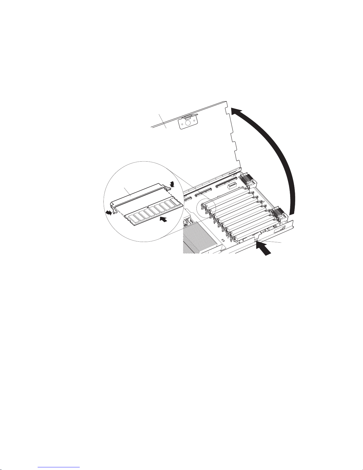
v
1.
2.
3.
4.
40
5.
6.
7.
on
8. To
a.
v
Install only 2.5 V, 184-pin, double-data-rate (DDR), PC2100, registered
synchronous dynamic random-access memory (SDRAM) with error correcting
code (ECC) DIMMs. These DIMMs must be compatible with the latest PC2100
SDRAM Registered DIMM specification, which is available from
http://www.jedec.org/.
Before you begin, read the documentation that comes with the DIMMs.
The following illustration shows how to install DIMMs on the processor board.
I/O-board tray
DIMM socket
DIMM 1
DIMM 2
DIMM 3
DIMM 4
DIMM 5
DIMM 6
DIMM 7
DIMM 8
I/O tray release
Complete the following steps to install a DIMM:
Review the safety information beginning on page 109 and “Installation
guidelines” on page 33.
Shut down the operating system, turn off the blade server, and remove the
blade server from the BladeCenter unit. See “Removing the blade server from
the BladeCenter unit” on page 39 for instructions.
Carefully lay the blade server on a flat, nonconductive surface.
Open the blade server cover (see “Opening the blade server cover” on page
for instructions) and lift it off the blade server.
Press the I/O-tray release and rotate the I/O-tray open, as shown in the
illustration. The I/O tray is hinged and will support itself in the open position.
Locate the DIMM connectors on the processor board. Determine the
connectors into which you will install the DIMMs (see the table on page 44.).
Touch the static-protective package that contains the DIMM option to any
unpainted metal surface on the BladeCenter chassis or any unpainted surface
any other grounded rack component. Then, remove the DIMM from the
package.
install the DIMMs, repeat the following steps for each DIMM that you install:
Turn the DIMM so that the DIMM keys align correctly with the connector on
the processor board.
Chapter 4. Installing options
45
Page 56

b.
9.
If
v
v
v
v
v
46
Attention: To avoid breaking the retaining clips or damaging the DIMM
connectors, handle the clips gently.
Insert the DIMM by pressing the DIMM along the guides into the connector.
Make sure that the retaining clips snap into the closed positions.
Important: If there is a gap between the DIMM and the retaining clips, the
DIMM has not been correctly installed. In this case, open the retaining clips
and remove the DIMM; then, reinsert the DIMM.
Before closing the I/O tray, check that all components are installed and seated
correctly and that you have not left loose tools or parts inside the blade server.
Pivot the I/O tray to the closed position until it clicks into place.
10.
you have other options to install or remove, do so now; otherwise, go to
“Completing the installation” on page 62.
Installing an additional microprocessor
The following notes describe the type of microprocessor that your blade server
supports and other information that you must consider when installing a
microprocessor:
Your blade server supports up to four microprocessors. With two or four
microprocessors, your blade server can operate as a symmetric multiprocessing
(SMP) server. With one or three microprocessors, the blade server will not
operate as an SMP server; however, installing more than one microprocessor will
still result in improved server performance, even if the blade server is not
configured for SMP operation. With SMP, certain operating systems and
application programs can distribute the processing load between the
microprocessors. To use SMP, obtain an SMP-capable operating system. For a
list of supported operating systems and other options, go to
http://www.ibm.com/pc/us/compat/.
Attention: To ensure proper server operation when you install an additional
microprocessor, use microprocessors that have the same cache size and type,
and the same clock speed. Internal and external clock frequencies of all
microprocessors installed in the server must be identical (including system bus
speed).
For a list of microprocessors supported by your blade server, go to the
ServerProven
Thoroughly review the documentation that comes with the microprocessor, so
that you can determine whether you need to update the blade server BIOS code.
The latest level of BIOS code for your blade server is available from the World
Wide Web. See Appendix A, “Getting help and technical assistance,” on page
107 for the World Wide Web addresses.
The microprocessor sockets in this blade server contain built-in termination for
the microprocessor bus; therefore, terminator cards are not required for empty
microprocessor sockets. However, for proper airflow, an empty microprocessor
socket must contain a microprocessor heat-sink filler, sometimes called a
microprocessor baffle.
The microprocessor speeds are automatically set for this blade server; therefore,
you do not need to set any microprocessor frequency-selection jumpers or
switches.
®
list at http://www.ibm.com/pc/us/compat/.
BladeCenter HS40 Type 8839: Hardware Maintenance Manual and Troubleshooting Guide
Page 57

1.
2.
3.
4.
40
5.
6.
7.
8.
9.
a.
b.
on
The following illustration shows how to install the additional microprocessors on the
processor board.
Microprocessor-locking lever
Heat sink
Heat-sink-retention
mechanism
Microprocessor
Microprocessorheat-sink filler
Complete the following steps to install an additional microprocessor:
Review the safety information beginning on page 109 and “Installation
guidelines” on page 33.
Shut down the operating system, turn off the blade server, and remove the
blade server from the BladeCenter unit. See “Removing the blade server from
the BladeCenter unit” on page 39 for instructions.
Carefully lay the blade server on a flat, nonconductive surface.
Open the blade server cover (see “Opening the blade server cover” on page
for instructions) and lift it off the blade server.
Lift and remove the air baffle covering the microprocessors.
Locate the microprocessor socket on the processor board. (See “Processor
board components” on page 35 for numbering order of processors.)
Note: Processors must be installed in order, starting with microprocessor 1,
Using a #2 screwdriver, loosen the captive screw on the heat-sink retention
mechanism, and rotate the mechanism up.
Remove the microprocessor heat-sink filler.
Install the microprocessor:
then microprocessors 2, 3, and 4.
Remove the protective cover, tape, or label from the surface of the
microprocessor socket, if one is present.
Touch the static-protective package containing the new microprocessor to
any unpainted metal surface on the BladeCenter chassis or any unpainted
surface on any other grounded rack component; then, remove the
microprocessor from the package.
Attention: Do not use any tools or sharp objects to lift the locking lever
the microprocessor socket. Failure to do so might result in permanent
damage to the processor board.
Chapter 4. Installing options
47
Page 58

or
d.
of
v Do
v
48
c.
Rotate the locking lever on the microprocessor socket from its closed and
locked position until it stops or clicks in the fully open position
(approximately a 135° angle), as shown.
Attention: You must make sure that the locking lever on the
microprocessor socket is in the fully open position before you insert the
microprocessor in the socket. Failure to do so might result in permanent
damage to the microprocessor, microprocessor socket, and processor
board.
Lever
fully
open
Lever closed
Lever closed
Center the microprocessor over the microprocessor socket. Align the
triangle on the corner of the microprocessor with the triangle on the corner
the socket, and carefully press the microprocessor into the socket.
Microprocessor
Alignment marks
Lever
fully
open
Microprocessor
socket
Attention:
Carefully close the lever to secure the microprocessor in the socket.
e.
BladeCenter HS40 Type 8839: Hardware Maintenance Manual and Troubleshooting Guide
not use excessive force when pressing the microprocessor into the
socket.
Make sure that the microprocessor is oriented and aligned correctly in
the socket before you try to close the lever.
Page 59

a.
is
1) Do
2) Do
If
10.
Install a heat sink on the microprocessor:
Remove the plastic protective cover from the bottom of the heat sink, if one
present.
Attention:
not set down the heat sink after you remove the plastic cover.
not touch the thermal grease on the bottom of the heat sink.
Touching the thermal grease will contaminate it. If the thermal grease
becomes contaminated, contact your service technician.
b.
Align and place the heat sink on top of the microprocessor. Press firmly on
the heat sink.
Lower the retention mechanism; then, screw down the captive mounting screw
11.
using a #2 Pillips screwdriver. Do not over-tighten the screw. If you are using a
torque wrench, tighten the screws to 8,5 to 13 Nm (6.3 to 9.6 foot-pounds).
Attention: To help ensure proper cooling and system reliability the air baffle
must be correctly positioned and fully seated.
12.
Install the air baffle covering microprocessor 1 and microprocessor 4, making
sure that the air baffle is positioned and pushed down so that both heat sink
captive mounting screws are through the holes in the air baffle.
Air baffle
13.
you have other options to install or remove, do so now; otherwise, go to
“Completing the installation” on page 62.
Installing an I/O expansion card
You can add one or two optional I/O expansion cards to your blade server to give
the blade server up to four additional network connections for communicating on a
network. Each I/O expansion card provides two additional network connections that
are routed through switch-module bays 3 and 4 of the BladeCenter unit. If two I/O
expansion cards are installed, both expansion cards must be of the same type.
Attention: When you add an I/O expansion card, you must make sure that the
switch modules in switch-module bays 3 and 4 on the BladeCenter unit both
support the I/O expansion card network-interface type. For example, if you add an
Ethernet expansion card to your blade server, the modules in switch-module bays 3
and 4 on the BladeCenter unit must both be compatible with the Ethernet expansion
card. All other I/O expansion cards that are installed on other blade servers in the
BladeCenter unit must also be compatible with these switch modules. In this
example, you could then install two Ethernet switch modules, two pass-thru
modules, or one Ethernet switch module and one pass-thru module. Because
pass-thru modules are compatible with a variety of I/O expansion cards, installing
two pass-thru modules would allow use of several different types of compatible I/O
expansion cards within the same BladeCenter unit.
Microprocessor 1 and 4
heat sink captive mounting screws
Chapter 4. Installing options
49
Page 60

If
be
1.
2.
3.
4.
5.
6.
a.
b.
c.
50
Important:
you are installing only one I/O expansion card in the blade server, it must
installed in I/O expansion card location 2.
The following illustration shows how to install an I/O expansion card on the blade
server. The same procedure is used to install an expansion card in either I/O
expansion card location; however, the illustration shows installing an expansion card
only in I/O expansion card location 2.
I/O expansion card
Screws
Screws
I/O expansion
card tray
Screws
Complete the following steps to install an I/O expansion card:
Review the safety information beginning on page 109 and “Installation
guidelines” on page 33.
Shut down the operating system, turn off the blade server, and remove the
blade server from the BladeCenter unit (see “Removing the blade server from
the BladeCenter unit” on page 39 for information).
Carefully lay the blade server on a flat, nonconductive surface.
Open the blade server cover (see “Opening the blade server cover” on page 40
for instructions), and lift it off the blade server.
Remove the two screws near connector J8H1 (or connector J4H1, if you are
installing an I/O expansion card in I/O expansion location 1) that secure the I/O
board to the chassis, as shown in the illustration.
Install the I/O expansion card:
Install the I/O expansion card tray. Secure the tray to the I/O board with the
four long screws from the option kit, as shown in the illustration.
Orient the I/O expansion card as shown in the illustration.
Slide the notch in the narrow end of the card into the raised hook on the
tray; then, gently pivot the wide end of the card into the I/O expansion card
connectors, as shown in the illustration.
BladeCenter HS40 Type 8839: Hardware Maintenance Manual and Troubleshooting Guide
Page 61

8. If
7.
See the documentation that comes with the I/O expansion card for device-driver
and configuration information to complete the installation of the I/O expansion
card. Some documentation might also be on the IBM BladeCenter
Documentation CD that comes with the BladeCenter unit.
you have other options to install or remove, do so now; otherwise, go to
“Completing the installation” on page 62.
Installing a PCI I/O expansion unit
You can install up to two PCI adapters by installing the Peripheral Card Interface
(PCI) I/O Expansion Unit on the blade server.
The following illustration shows how to install a PCI I/O Expansion Unit on a blade
server.
PCI I/O Expansion Unit
option
Blade expansion
connector terminator
Cover
pins
Air baffle
For complete information about installing this expansion unit, see the Installation
Instructions that comes with the optional expansion unit.
Installing a SCSI storage expansion unit
Attention: You must install a SCSI storage expansion unit that is specified for use
with the IBM HS40 Type 8839 blade server. Two types of SCSI storage expansion
units are available for BladeCenter products, only one of which is compatible with
the IBM HS40 Type 8839 blade server. See the ServerProven list at
http://www.ibm.com/pc/us/compat/ for more information.
Chapter 4. Installing options
51
Page 62

1.
2.
3.
52
To use SCSI hard disk drives with your blade server, install a SCSI storage
expansion unit, such as the IBM BladeCenter SCSI Storage Expansion Unit, on the
blade server. You will then be able to install two 3.5-inch, hot-swap, SCSI, 1-inch
(26 mm) slim-high hard disk drives in the expansion unit, for use by the blade
server. The SCSI controller in the BladeCenter SCSI storage expansion unit
supports embedded mirroring, which is similar to RAID level-1.
Important: To avoid potential performance and reliability problems when
configuring or replacing drives in a mirrored configuration, make sure
that the storage capacities and speeds of the drives are identical.
After you install the SCSI storage expansion unit on your blade server, the blade
server and expansion unit are a unit that occupies three blade bays in the
BladeCenter unit.
Attention: To ensure proper cooling and system reliability, make sure that each of
the SCSI hard disk drive bays on the SCSI storage expansion unit contains either a
hot-swap SCSI hard disk drive or a filler panel.
Complete the following steps to install the SCSI storage expansion unit.
Note: The illustrations used in this procedure depict the installation process on a
BladeCenter HS40 blade server in a BladeCenter Type 8677 unit. These
illustrations might differ slightly from your hardware. However, this installation
process is the same regardless of the BladeCenter unit.
Review the safety information beginning on page 109 and “Installation
guidelines” on page 33.
Shut down the operating system, turn off the blade server, and remove the
blade server from the BladeCenter unit (see “Removing the blade server from
the BladeCenter unit” on page 39 for instructions).
Carefully lay the blade server on a flat, nonconductive surface.
BladeCenter HS40 Type 8839: Hardware Maintenance Manual and Troubleshooting Guide
Page 63

a.
b.
5.
6.
4.
Remove the blade server cover.
Open the blade server cover (see “Opening the blade server cover” on
page 40 for instructions), and lift it off the blade server.
Blade cover
Cover
pins
Blade-cover
release
Air baffle
Blade-cover
release
Store the cover in a safe place.
Locate the blade expansion connector on the processor board and remove the
terminator from the connector.
Blade expansion
connector terminator
Before installing the SCSI storage expansion unit, check that all components
are installed and seated correctly and that you have not left loose tools or
parts inside the blade server.
Attention: To help ensure proper cooling and system reliability, the air baffle
must be correctly positioned and fully seated.
Chapter 4. Installing options
53
Page 64

is
8.
54
7.
Make sure that the air baffle covering microprocessor 1 and microprocessor 4
positioned and pushed down so that both heat sink captive mounting screws
are through the holes in the air baffle.
Air baffle
Microprocessor 1 and 4
heat sink captive mounting screws
Install the SCSI storage expansion unit:
BladeCenter HS40 Type 8839: Hardware Maintenance Manual and Troubleshooting Guide
Page 65

a.
b.
Attention: Install only a SCSI storage expansion unit that is specified for use
with the IBM HS40 Type 8839 blade server. Compatible SCSI storage
expansion units do not have a shield, as shown in the following illustration.
Use SCSI storage expansion
unit with no shield
Do not use SCSI storage expansion
with shield
No shield Shield
Orient the storage expansion unit as shown in the illustration.
SCSI storage
expansion unit
Cover pins
Blade-cover
release
Air baffle
Blade-cover
release
Lower the storage expansion unit so that the slots at the rear slide down
onto the pins at the rear of the blade server.
Chapter 4. Installing options
55
Page 66

9.
If
56
c.
Pivot the storage expansion unit closed, and press it firmly into place until
the cover-release latches click. The connector on the expansion unit
automatically aligns with and connects to the blade expansion connector
(J3A1) on the processor board.
Insert the combined blade and expansion unit into three adjacent BladeCenter
unit bays.
Note: When any blade server or option is in blade bay 7 through 14 (in the
10.
Turn on the blade server.
11.
you have not already done so, install the LSI SCSI device drivers for your
operating system. LSI device drivers are on the ServerGuide Setup and
BladeCenter HS40 Type 8839: Hardware Maintenance Manual and Troubleshooting Guide
BladeCenter unit) or blade bay 5 through 8 (in the BladeCenter T unit),
power modules must be present in all four power bays.
Page 67

to
0
1
is
If
If a
Installation CD that comes with the BladeCenter unit. You can also get the
latest version of the drivers from the IBM Support Web site at
http://www.ibm.com/pc/support/.
the storage expansion unit installed on your blade server, you can install up to
With
two hot-swap SCSI hard disk drives in the expansion unit and configure them for
embedded mirroring (RAID level 1). Each SCSI device must have a unique SCSI
ID. This ID enables the SCSI controller in the expansion option to identify the
device and ensure that different devices on the same SCSI channel do not attempt
transfer data simultaneously. The SCSI IDs for the hard disk drives in the
expansion unit are permanent (not configurable). Table 2 lists the SCSI IDs for the
hard disk drives that are installed in the expansion unit. See “Installing a SCSI
hot-swap hard disk drive” for instructions for installing hard disk drives.
Table 2. SCSI IDs for hot-swap hard disk drives in the expansion unit
Device
Drive bay 1
Drive bay 2
SCSI ID
Note: SCSI ID 7 is usually reserved for the SCSI controller; however, this SCSI ID
changeable through the ServeRAID
configuration utility program.
Use the Configuration/Setup Utility program in the blade server to enable or disable
the SCSI controller in the storage expansion unit. See the documentation that
comes with the storage expansion unit for information about configuring the storage
expansion unit and SCSI hard disk drives.
Installing a SCSI hot-swap hard disk drive
you have installed a SCSI storage expansion unit on the blade server, you can
install up to two SCSI hot-swap hard disk drives in the bays in the expansion unit.
hot-swap hard disk drive in the expansion unit fails, you can replace it without
turning off the blade server. Therefore, you have the advantage of continuing to
operate your blade server while a hard disk drive in this unit is removed or installed.
Each hot-swap drive has two indicator LEDs. If the amber hard disk drive status
LED for a drive is lit continuously, that drive is faulty and must be replaced.
Each hot-swap drive that you plan to install must be mounted in a hot-swap-drive
tray. The drive must have a Single Connector Attachment (SCA) connector.
Hot-swap-drive trays come with hot-swap drives.
™
configuration program or the LSI
Chapter 4. Installing options
57
Page 68

1.
2.
3.
a.
b.
c.
d.
e.
v If
v If
58
The following illustration shows how to install a SCSI hot-swap hard disk drive.
Note: The illustrations used in this procedure depict the installation process on a
BladeCenter HS40 blade server in a BladeCenter Type 8677 unit. These
illustrations might differ slightly from your hardware. However, this installation
process is the same regardless of the BladeCenter unit.
Filler panel
Blade
Drive handle
(in open position)
Storage
expansion unit
Hard disk drive
Complete the following steps to install a drive in a storage expansion unit.
Attention: To maintain proper system cooling, do not operate the BladeCenter
unit for more than 1 minute without either a hot-swap hard disk drive or a filler
panel installed in each storage expansion unit bay.
Review the safety information beginning on page Appendix B, “Safety
information,” on page 109 and “Installation guidelines” on page 33.
Remove the filler panel from one of the empty hot-swap bays by inserting your
finger into the depression at the top of the filler panel and pulling it away from
the expansion unit.
Install the SCSI hot-swap hard disk drive:
Make sure that the tray handle is open (that is, perpendicular to the hard
disk drive).
Align the hard disk drive assembly with the guide rails in the bay.
Gently push the hard disk drive assembly into the bay until the drive stops.
Push the tray handle to the closed (locked) position.
Check the hard disk drive LEDs to make sure that the hard disk drive is
operating correctly.
the amber hard disk drive status LED for a hard disk drive is lit
continuously, the hard disk drive is faulty and needs to be replaced.
the green hard disk drive activity LED is flashing, the hard disk drive is
being accessed.
See the documentation that comes with the expansion unit for information about
configuring the expansion unit and SCSI hard disk drives.
BladeCenter HS40 Type 8839: Hardware Maintenance Manual and Troubleshooting Guide
Page 69

If a
1.
2.
of
3.
4.
5.
If
Replacing a SCSI hot-swap hard disk drive
hard disk drive in the storage expansion unit fails, you can replace it without
turning off the blade server.
Complete the following steps to replace a SCSI hot-swap hard disk drive in a
storage expansion unit hot-swap bay.
Note: The illustrations used in this procedure depict the installation process on a
BladeCenter HS40 blade server in a BladeCenter Type 8677 unit. These
illustrations might differ slightly from your hardware. However, this installation
process is the same regardless of the BladeCenter unit.
Hard disk drive
Blade server
Filler panel
Storage
expansion unit
Attention: To maintain proper system cooling, do not operate the BladeCenter
unit for more than 1 minute without either a hot-swap hard disk drive or a filler
panel installed in each storage expansion unit bay.
Review the safety information beginning on page 109 and “Installation
guidelines” on page 33.
Locate the defective hard disk drive (look for an amber status LED on the front
the hard disk drive).
Make sure that the hard disk drive has stopped spinning.
Move the handle on the hard disk drive to the open position (perpendicular to
the hard disk drive), and pull the hot-swap hard disk drive assembly from the
bay.
Within 1 minute, install the replacement hard disk drive in the hot-swap bay (see
“Installing a SCSI hot-swap hard disk drive” on page 57 for instructions).
Replacing the battery
IBM has designed this product with your safety in mind. The lithium battery must be
handled correctly to avoid possible danger. If you replace the battery, you must
adhere to the following instructions.
Note: In the U. S., call 1-800-IBM-4333 for information about battery disposal.
you replace the original lithium battery with a heavy-metal battery or a battery with
heavy-metal components, be aware of the following environmental consideration.
Chapter 4. Installing options
59
Page 70

To
a
Do
v
v
v
of
1.
2.
3.
4.
40
60
Batteries and accumulators that contain heavy metals must not be disposed of with
normal domestic waste. They will be taken back free of charge by the manufacturer,
distributor, or representative, to be recycled or disposed of in a proper manner.
order replacement batteries, call 1-800-426-7378 within the United States, and
1-800-465-7999 or 1-800-465-6666 within Canada. Outside the U.S. and Canada,
call your IBM reseller or IBM marketing representative.
Note: After you replace the battery, you must reconfigure your blade server and
reset the system date and time.
Statement 2:
CAUTION:
When replacing the lithium battery, use only IBM Part Number 33F8354 or an
equivalent type battery recommended by the manufacturer. If your system has
module containing a lithium battery, replace it only with the same module
type made by the same manufacturer. The battery contains lithium and can
explode if not properly used, handled, or disposed of.
not:
Throw or immerse into water
Heat to more than 100°C (212°F)
Repair or disassemble
Dispose
the battery as required by local ordinances or regulations.
Complete the following steps to replace the battery:
Review the safety information beginning on page 109 and “Installation
guidelines” on page 33.
Follow any special handling and installation instructions supplied with the
battery.
Turn off the blade server and remove the blade from the BladeCenter unit (see
“Removing the blade server from the BladeCenter unit” on page 39 for
instructions).
Open the blade server cover (see “Opening the blade server cover” on page
for instructions) and lift it off the blade server.
BladeCenter HS40 Type 8839: Hardware Maintenance Manual and Troubleshooting Guide
Page 71
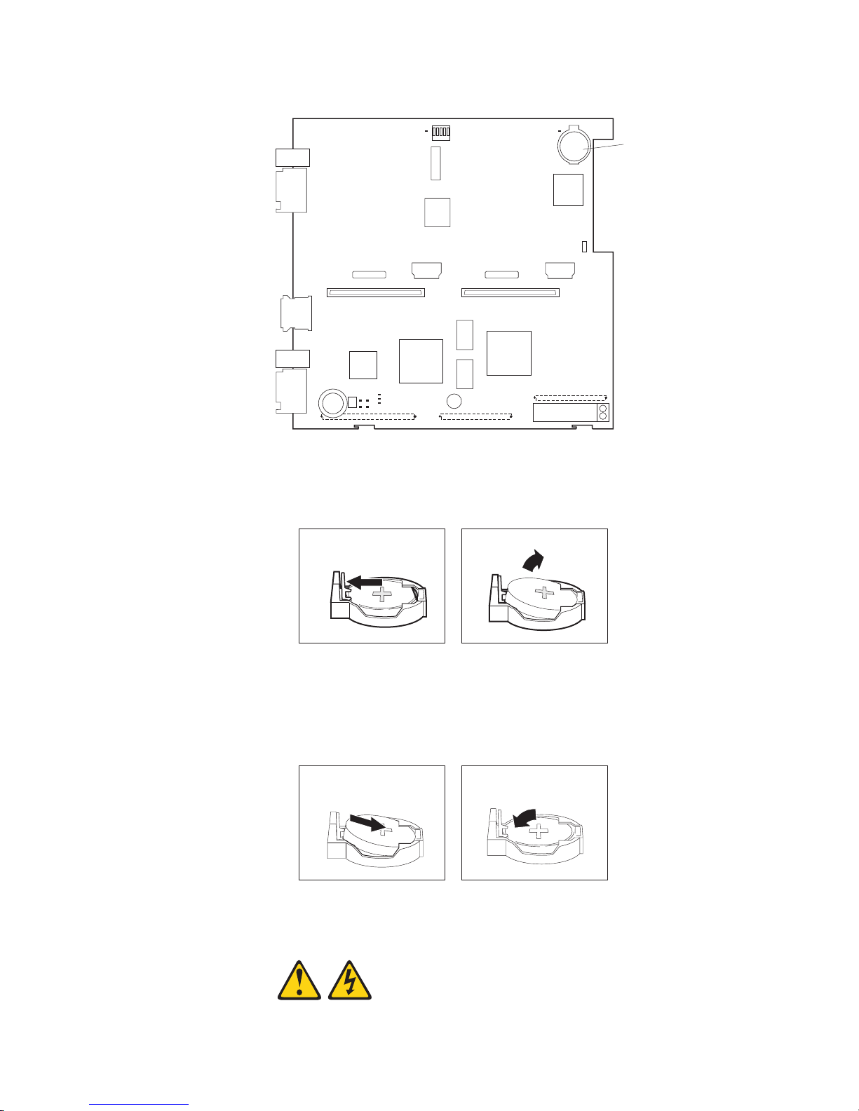
6.
a.
b.
7.
a.
b. As
8.
5.
Locate the battery on the I/O board.
Battery
Remove the battery:
Use your fingers to pinch the battery retainer; then, rotate the battery up
and out from its socket.
Use your fingernail to slide the battery out from under the battery clip.
Insert the new battery:
Tilt the battery so that you can insert it into the socket, under the battery
clip.
you slide it under the battery clip, press the battery down into the
socket until the battery retainer secures it in place.
Close the blade server cover (see “Closing the blade server cover” on page
63).
Statement 21:
Chapter 4. Installing options
61
Page 72

9.
To
1.
2.
3.
4.
If
62
CAUTION:
Hazardous energy is present when the blade server is connected to the
power source. Always replace the blade cover before installing the blade
server.
Reinsert the blade server into the bay in the BladeCenter unit.
10.
Turn on the blade server.
11.
Start the blade server Configuration/Setup Utility program and set configuration
parameters as needed (see “Using the Configuration/Setup Utility program” on
page 11 for information).
Completing the installation
complete the installation, perform the following tasks. Instructions for each task
are in the following sections.
Reinstall the blade server bezel assembly, if you removed it (see “Installing the
blade server bezel assembly”).
Attention: To help ensure proper cooling and system reliability, the air baffle
must be correctly positioned and fully seated.
Close the blade server cover, unless you installed the SCSI storage expansion
unit option (see “Closing the blade server cover” on page 63).
Statement 21:
CAUTION:
Hazardous energy is present when the blade server is connected to the
power source. Always replace the blade cover before installing the blade
server.
Reinstall the blade server into the BladeCenter unit (see “Installing the blade
server in the BladeCenter unit” on page 65).
Turn on the blade server (see “Turning on the blade server” on page 6).
Note: Reinstall the bezel assembly on the BladeCenter T unit after you have
finished turning on the blades. However, if you installed an option such as a
PCI I/O Expansion Unit with PCI adapters that require cables, you will not be
able to install the bezel assembly, which contains an air filter for the
BladeCenter T unit. If you cannot install the bezel assembly, a filter must be
provided on the rack. See the IBM Eserver BladeCenter T Planning and
Installation Guide for information about installing an air filter on the rack (you
can obtain the planning guide from http://www.ibm.com/pc/support/).
For certain options, run the blade server Configuration/Setup Utility program
5.
(see “Updating your blade server configuration” on page 67).
Note:
you have just connected the power cords of your BladeCenter unit to
electrical outlets, you will have to wait until the power-on LED on the blade
server flashes slowly before pressing the power-control button on a blade
server.
Installing the blade server bezel assembly
Complete the following steps to install the blade server bezel assembly.
BladeCenter HS40 Type 8839: Hardware Maintenance Manual and Troubleshooting Guide
Page 73

2.
3.
at
1.
Review the safety information beginning on page 109 and “Installation
guidelines” on page 33.
Connect the control-panel cable to the control-panel connector on the processor
board.
Control-panel
connector
Control-panel
cable
Insert the tabs on the bottom of the bezel up into the matching holes on the
server chassis; then, rotate the top of the bezel toward the server until the tabs
the top of the bezel snap into place.
Closing the blade server cover
Important: The blade server cannot be inserted into the BladeCenter unit until the
cover is installed and closed or a SCSI storage expansion unit is installed. Do not
attempt to override this protection.
Chapter 4. Installing options
63
Page 74

1.
2. If
3.
4.
5.
of
6.
64
The following illustration shows how to close the blade server cover.
Blade cover
Cover
pins
Air baffle
Complete the following steps to close the blade server cover:
Review the safety information beginning on page 109 and “Installation
guidelines” on page 33.
you removed the blade bezel assembly, replace it now. See “Installing the
blade server bezel assembly” on page 62 for instructions.
Before closing the cover, check that all components are installed and seated
correctly and that you have not left loose tools or parts inside the blade server.
Attention: To help ensure proper cooling and system reliability the air baffle
must be correctly positioned and fully seated.
Make sure that the air baffle covering microprocessor 1 and microprocessor 4 is
positioned and pushed down so that both heat sink captive mounting screws are
through the holes in the air baffle.
Air baffle
Lower the cover so that the slots at the rear slide down onto the pins at the rear
the blade server, as shown in the illustration.
Pivot the cover to the closed position as shown in the illustration, until it clicks
into place.
BladeCenter HS40 Type 8839: Hardware Maintenance Manual and Troubleshooting Guide
Microprocessor 1 and 4
heat sink captive mounting screws
Page 75

1.
2. If
3.
a.
Installing the blade server in the BladeCenter unit
Note: The illustrations used in this procedure depict the installation process on a
BladeCenter HS40 blade server in a BladeCenter Type 8677 unit. These
illustrations might differ slightly from your hardware. However, this installation
process is the same regardless of the BladeCenter unit.
Blade server
Filler blade
Complete the following steps to install a blade server in the BladeCenter unit.
Statement 21:
CAUTION:
Hazardous energy is present when the blade server is connected to the power
source. Always replace the blade cover before installing the blade server.
Attention: If you reinstall a blade that you removed, you must install it in the
same bays from which you removed it. Some blade server configuration information
and update options are established according to bay number. Reinstalling a blade
server into different bays than those from which it was removed could have
unintended consequences, and you might need to reconfigure the blade server.
Review the safety information beginning on page 109 and “Installation
guidelines” on page 33 through “Handling static-sensitive devices” on page 33.
you have not done so already, install any required options, such as
microprocessors or memory, in the blade server.
Select the bays for the blade server.
Notes:
The HS40 blade server requires two adjacent bays.
Chapter 4. Installing options
65
Page 76
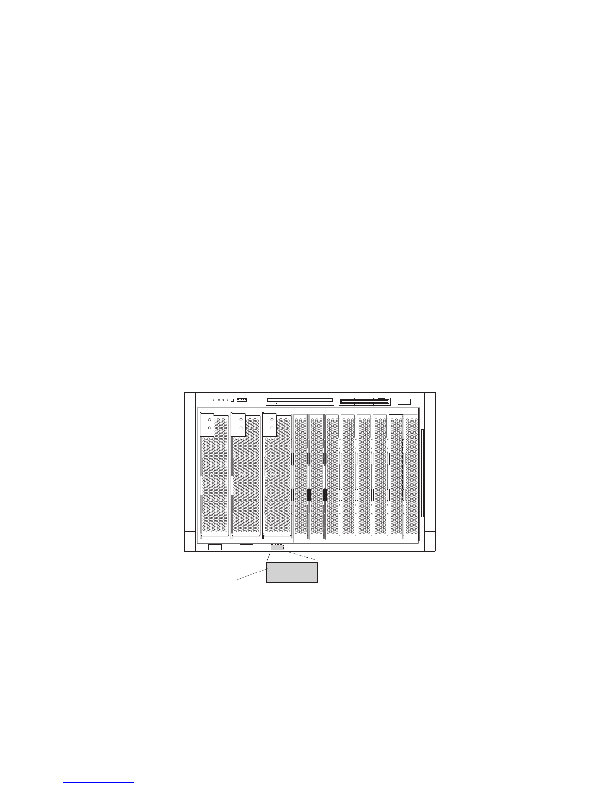
If
c.
Do
4.
5.
6.
7.
8.
9.
66
b.
the blade server has a SCSI storage expansion unit installed on it, the
blade server and expansion option require three adjacent bays.
When any blade server or option is in blade bays 7 through 14, power
modules must be installed in power bays 1 and 2, and power modules
must be installed in power bays 3 and 4.
Attention: To help ensure proper cooling, performance, and system
reliability, make sure that each of the blade bays on the front of the
BladeCenter unit has a blade server, expansion unit, or filler blade installed.
not operate the BladeCenter unit for more than 1 minute or the
BladeCenter T unit for more than 20 minutes without either a blade server,
expansion unit, or filler blade installed in each blade bay.
Make sure that the release levers on the blade server are in the open position
(perpendicular to the blade).
Slide the blade server into the bay until it stops. The spring-loaded doors
further back in the bay that cover the bay opening move out of the way as you
insert the blade server.
Push the release levers on the front of the blade server closed.
Turn on the blade server. See “Turning on the blade server” on page 6 for
instructions.
Make sure that the power-on LED on the blade control panel is lit continuously,
indicating that the blade server is receiving power and is turned on.
Write identifying information on one of the user labels that comes with the
blade server; then, place the label on the BladeCenter unit bezel just below the
blade server, as shown in the following illustration.
CD CD
CD
User
label
Important: Do not place the label on the blade server or block the ventilation
holes on the blade server in any way.
BladeCenter HS40 Type 8839: Hardware Maintenance Manual and Troubleshooting Guide
Page 77

If
as a
T
If
The following illustration shows the placement of the label, just to the side of
the blade server, on the BladeCenter T unit.
CMM
1
CD
CMM
2
User
CD
CD
10.
you have other blades to install, do so now.
Note: Reinstall the bezel assembly on the BladeCenter T unit after you have
finished turning on the blades. However, if you installed an option such
PCI I/O Expansion Unit with PCI adapters that require cables, you
will not be able to install the bezel assembly, which contains an air filter
for the BladeCenter T unit. If you cannot install the bezel assembly, a
filter must be provided on the rack. See the IBM Eserver BladeCenter
Planning and Installation Guide for information about installing an air
filter on the rack (you can obtain the planning guide from
http://www.ibm.com/pc/support/).
label
If this is the initial installation for a blade server in the BladeCenter unit, you must
configure the blade server with the blade server Configuration/Setup Utility and
install the blade server operating system. See “Updating your blade server
configuration” and the IBM Eserver BladeCenter HS40 Type 8839 Installation and
User’s Guide for details.
Updating your blade server configuration
When you start your blade server for the first time after you add or remove an
internal option or external SCSI device (if the storage expansion unit has been
installed), you might receive a message that the configuration has changed. The
blade server Configuration/Setup Utility program starts automatically so that you can
save the new configuration settings. For more information, see “Using the
Configuration/Setup Utility program” on page 11.
Some options have device drivers that you must install. See the documentation that
comes with each option for information about installing device drivers.
your blade server comes with more than one microprocessor or if your blade
server comes with one microprocessor and you have installed additional
microprocessors, your blade server might be able to operate as an SMP server. You
Chapter 4. Installing options
67
Page 78

68
might need to upgrade the operating system to support SMP. For more information,
see IBM Eserver BladeCenter HS40 Type 8839 Installation and User’s Guide and
your operating-system documentation.
Input/output connectors and devices
The input/output connectors that are available to your blade server are supplied by
the BladeCenter unit. See the documentation that comes with your BladeCenter unit
for information about the input/output connectors.
The blade server has two selection buttons on the control panel: the
CD/diskette/USB select button and the keyboard/mouse/video select button. See
“Controls and LEDs” on page 8 for information about these buttons and their
functions.
The Ethernet controllers on your blade server communicate with the network
through the Ethernet-compatible switch modules on the BladeCenter unit. Network
signals to and from the blade server or any I/O expansion cards are automatically
routed to a same-network-interface switch module through circuitry in the
BladeCenter unit.
BladeCenter HS40 Type 8839: Hardware Maintenance Manual and Troubleshooting Guide
Page 79

v
v
v
1.
2.
3.
4.
on
5.
6.
©
Chapter 5. Service replaceable units
This chapter describes the removal of server components.
Important: The field replaceable unit (FRU) procedures are intended for trained
servicers who are familiar with IBM products. See the parts listing in
Chapter 7, “Parts listing, Type 8839,” on page 105 to determine
whether a component being replaced is a customer replaceable unit
(CRU) or a FRU.
Microprocessor removal
Note:
Read “Installation guidelines” on page 33.
Read the safety notices beginning on page 109.
Read “Handling electrostatic discharge-sensitive devices” on page 112.
Complete
the following steps to remove a microprocessor:
Shut down the operating system, turn off the blade server, and remove the
blade server from the BladeCenter unit (see “Removing the blade server from
the BladeCenter unit” on page 39).
Carefully lay the blade server on a flat, nonconductive surface.
Open the blade server cover (see “Opening the blade server cover” on page 40
for instructions).
Remove the bezel assembly (see “Removing the blade server bezel assembly”
page 42 for instructions).
Identify the microprocessor to be removed.
Note: If you are replacing a failed microprocessor, make sure that you have
selected the correct microprocessor for replacement (see “Light path
diagnostics” on page 86).
Remove the air baffle.
Copyright IBM Corp. 2004
69
Page 80

a.
b.
8.
70
7.
Remove the heat sink:
Loosen the captive screw, and lift the retention bar.
Gently pull the heat sink off the microprocessor.
Rotate the locking lever on the microprocessor socket from its closed and
locked position until it stops or clicks in the fully open position (approximately
135° angle), as shown.
Attention: You must make sure that the locking lever on the microprocessor
socket is in the fully open position before you remove the microprocessor from
the socket. Failure to do so might result in permanent damage to the
microprocessor, microprocessor socket, and system board.
Lever
Lever closed
fully
open
BladeCenter HS40 Type 8839: Hardware Maintenance Manual and Troubleshooting Guide
Lever closed
Lever
fully
open
Page 81

To
9.
Lift the microprocessor out of the socket.
install a microprocessor, see “Installing an additional microprocessor” on page 46
for instructions.
Attention: If you are not installing a replacement microprocessor in socket 2, you
must reinstall the microprocessor baffle in that socket.
Chapter 5. Service replaceable units
71
Page 82

v
v
v
on
1.
2.
3.
4.
is
5.
6.
v
v
72
Thermal grease
This section contains information about removing and replacing the thermal grease
between the heat sink and the microprocessor. The thermal grease must be
replaced whenever the heat sink has been removed from the top of the
microprocessor and is going to be reused or when debris is found in the grease.
Note:
Read “Installation guidelines” on page 33.
Read the safety notices beginning on page 109.
Read “Handling electrostatic discharge-sensitive devices” on page 112.
Complete
the following steps to replace damaged or contaminated thermal grease
the microprocessor and heat sink:
Place the heat sink on a clean work surface.
Remove the cleaning pad from its package, and unfold it completely.
Use the cleaning pad to wipe the thermal grease from the bottom of the heat
sink.
Note: Be sure that all of the thermal grease is removed.
Use a clean area of the cleaning pad to wipe the thermal grease from the
microprocessor; then, dispose of the cleaning pad after all of the thermal grease
removed.
Use the thermal grease syringe to place 16 uniformly spaced dots of 0.01 mL
each on the top of the microprocessor.
Microprocessor
0.01 mL of
thermal grease
Note: 0.01 mL is one tick mark on the syringe. If the grease is properly applied,
Install the heat sink onto the microprocessor as described in “Installing an
additional microprocessor” on page 46.
Processor board
When replacing the processor board, you must either update the system with the
latest firmware or restore the pre-existing firmware that the customer provides on a
diskette or CD image.
Note:
Read “Installation guidelines” on page 33.
Read the safety notices beginning on page 109.
BladeCenter HS40 Type 8839: Hardware Maintenance Manual and Troubleshooting Guide
approximately half (0.22 mL) of the grease will remain in the syringe.
Page 83

1.
2.
3.
4.
5.
6.
a. A
b. A
8.
v
Read “Handling electrostatic discharge-sensitive devices” on page 112.
Complete
the following steps to remove the processor board:
Shut down the operating system, and turn off the blade server (see “Turning off
the blade server” on page 7).
Remove the blade server from the BladeCenter unit (see “Removing the blade
server from the BladeCenter unit” on page 39).
Remove the blade server bezel assembly (see “Removing the blade server
bezel assembly” on page 42).
Remove the blade server cover (see “Opening the blade server cover” on page
40) or SCSI storage expansion unit (see “Installing a SCSI storage expansion
unit” on page 51).
Pivot the I/O board tray to the upward position.
Remove all components (see the appropriate installation instructions and
reverse the steps), and place them on a static-protective surface for
reinstallation.
Notes:
microprocessor assembly comes with a new heat sink.
processor board does not come with a heat sink. When replacing the
processor board and reinstalling an existing microprocessor, be sure to
re-install the heat sink (see “Thermal grease” on page 72).
Remove the six screws that secure the heat-sink retention bracket to the
7.
processor board and the blade server chassis, and put the screws and the
module in a safe place.
Remove the heat-sink retention bracket from the blade server.
Chapter 5. Service replaceable units
73
Page 84

9.
v
v
v
1.
2.
3.
4.
5.
6.
74
Note the alignment of the heat-sink retention bracket (the arrow on the bracket
aligns with the arrow on the processor board). You will need to align the bracket
the same way when reinstalling it.
Remove the processor board carefully from the blade server chassis.
I/O board
Reverse these steps to install the replacement processor board.
Note: Two self-adhesive labels come with the processor board. Apply one on top of
the existing Ethernet MAC address label on the bottom of the blade chassis.
The other label remains with the owner.
When replacing the I/O board, you must either update the system with the latest
firmware or restore the pre-existing firmware that the customer provides on a
diskette or CD image.
Note:
Read “Installation guidelines” on page 33.
Read the safety notices beginning on page 109.
Read “Handling electrostatic discharge-sensitive devices” on page 112.
Complete
the following steps to remove the I/O board:
Shut down the operating system, and turn off the blade server (see “Turning off
the blade server” on page 7).
Remove the blade server from the BladeCenter unit (see “Removing the blade
server from the BladeCenter unit” on page 39).
Remove the blade server bezel assembly (see “Removing the blade server
bezel assembly” on page 42).
Remove the blade server cover (see “Opening the blade server cover” on page
40) or SCSI storage expansion unit (see “Installing a SCSI storage expansion
unit” on page 51).
Pivot the I/O board tray to the upward position, and remove the cable
connecting the I/O board to the processor board.
Remove all components (see the appropriate installation instructions and
reverse the steps), and place them on a static-protective surface for
reinstallation.
BladeCenter HS40 Type 8839: Hardware Maintenance Manual and Troubleshooting Guide
Page 85

8.
7.
Remove the other seven screws that secure the I/O board to the blade chassis,
and put the screws in a safe place.
Pull the I/O board carefully out of the blade chassis.
Reverse these steps to install the replacement I/O board.
Chapter 5. Service replaceable units
75
Page 86

76
BladeCenter HS40 Type 8839: Hardware Maintenance Manual and Troubleshooting Guide
Page 87

1.
2.
3.
a
1
1.
2.
6
1.
2.
7
1.
2.
©
Chapter 6. Symptom-to-FRU index
Use this index to aid in locating failing or failed components in the HS40 Type 8839
blade server.
Notes:
Check the configuration before you replace a FRU. Configuration problems can
cause false errors and symptoms.
For IBM devices not supported by this index, refer to the manual for that device.
Always start with “Checkout procedure” on page 21.
The symptom-to-FRU index lists symptoms, errors, and the possible causes of
common failures. The most likely cause is listed first. Use this symptom-to-FRU
index to help you decide which FRUs to have available when servicing the server.
The left column of the tables in this index lists error codes or messages, and the
right column lists one or more suggested actions or FRUs to replace.
Note: In tables with more than two columns, multiple columns are required to
describe the error symptoms.
Take the action (or replace the FRU) suggested first in the list of the right column,
then restart the server to see if the problem has been corrected before taking
further action.
Note: Reseat a suspected component or reconnect a cable before replacing the
component.
POST error codes and messages are displayed on the screen and in the
management-module error log.
Beep codes
Beep symptoms are short tones or a series of short tones separated by pauses that
indicate system-error conditions. Both the system BIOS and the baseboard
management controller (BMC) emit beep codes (see the following two sections).
BIOS-generated beep codes
The following table lists the POST error beep codes. Typically, prior to system video
initialization, the BIOS uses these beep codes to inform users of error conditions.
Note: See Chapter 7, “Parts listing, Type 8839,” on page 105 to determine which components should be replaced by
field service technician.
Number of beeps/symptom
FRU/action
(Memory refresh timer error)
(Keyboard controller BAT test error)
(General exception error.)
Copyright IBM Corp. 2004
DIMM
Processor board
I/O board
Processor board
I/O board
Processor board
77
Page 88

a
5
1.
2.
3.
6
1.
2.
3.
7
1.
2.
1.
2.
1.
2.
1.
2.
1.
2.
3.
4.
1.
2.
3.
4.
5.
a
No
No
78
Note: See Chapter 7, “Parts listing, Type 8839,” on page 105 to determine which components should be replaced by
field service technician.
Number of beeps/symptom
short, 1 long
(No memory found in system)
FRU/action
Install or reseat memory, then perform a blade server reset.
DIMMs.
Processor board.
short, 1 long
(Memory is not DDR type)
Replace with supported DIMMs.
DIMMs.
Processor board.
short, 1 long
(SMBUS error. Memory
enumerations cannot proceed.)
Processor board
I/O board
Baseboard management controller (BMC) beep codes
The following table lists the BMC error beep codes.
Beep code/symptom
1-5-1-1 (Microprocessor
failure)
1-5-2-2 (No
microprocessors)
1-5-2-3 (VID mismatch,
population rules violation,
microprocessor mismatch)
1-5-4-2 (Power fault: dc
power unexpectedly lost)
1-5-4-4 (Power control fault)
FRU/action
Microprocessor
Processor board
Microprocessor
Processor board
Make sure all microprocessors are supported by the
BIOS and of the same family, model, stepping, speed,
and cache size.
Microprocessor.
Reseat blade server and power cycle the blade
server.
Reseat dc power cable.
Processor board.
I/O board.
Reseat blade server and power cycle the blade
server.
Flex cable.
Auxiliary power cable.
Processor board.
I/O board.
No-beep symptoms
Note: See Chapter 7, “Parts listing, Type 8839,” on page 105 to determine which components should be replaced by
field service technician.
No-beep symptom
beep and no video (System
error LED is OFF)
beep and no video (System
Attention LED is ON)
BladeCenter HS40 Type 8839: Hardware Maintenance Manual and Troubleshooting Guide
FRU/action
See “Undetermined problems” on page 101.
See “Diagnosing problems using the light path diagnostics feature” on page
27.
Page 89

In
a
1.
2.
3.
1.
2.
1.
2.
3.
4.
1.
2.
3.
4.
POST error codes
The following table lists error codes that might be sent to the management module
for error logging as BMC pass-through error entries for the management module
system-error log (SEL).
Note: The syntax of error logging between the management module and the SEL
might be different. Local SEL error codes might differ from the SEL entries
logged by the management module for identical event types.
the following error codes, X can be any number or letter.
Note: See Chapter 7, “Parts listing, Type 8839,” on page 105 to determine which components should be replaced by
field service technician.
Error code/symptom
0000
(Timer error)
0005
(CMOS checksum bad loading defaults)
0012
(CMOS date/time not set)
0040
(Refresh timer test failed)
0044
(DMA controller error)
0045
(DMA-1 error)
0046
(DMA-2 error)
004C
(Keyboard/interface error)
004D
(Primary master hard disk error)
004F
(Secondary master hard disk error)
0055
(Primary master drive - ATAPI
incompatible)
0057
(Secondary master drive - ATAPI
incompatible)
005D
(ATA SMART failure error (dynamic string))
FRU/action
Run diagnostics.
Battery.
I/O board.
Information only; no action required.
Run the Configuration/Setup Utility program, and set the date and
time.
I/O board
Processor board
I/O board
I/O board
I/O board
I/O board
Reset primary hard disk.
Run diagnostics.
Primary hard disk.
I/O board.
Reset secondary hard disk.
Run diagnostics.
Secondary hard disk.
I/O board.
Primary master hard disk drive
Secondary master hard disk drive
ATA drive
Chapter 6. Symptom-to-FRU index
79
Page 90

a
1.
2.
1.
2.
1.
2.
3.
1.
2.
3.
4.
1.
2.
3.
4.
1.
2.
3.
4.
1.
2.
3.
4.
1.
2.
1.
2.
1.
2.
1.
2.
1.
2.
80
Note: See Chapter 7, “Parts listing, Type 8839,” on page 105 to determine which components should be replaced by
field service technician.
Error code/symptom
196
(Processor cache mismatch detected)
198
(Processor speed mismatch detected)
289
(Non-matching or missing DIMMs, user
has not installed DIMMs correctly, or
DIMM disabled by POST or user)
8120
(Microprocessor 1 thermal trip error)
FRU/action
Microprocessor
Processor board
Microprocessor
Processor board
Run the Configuration/Setup Utility program.
Disabled DIMM.
System board
Check cooling.
Replace blowers if needed.
Run the Configuration/Setup Utility program, and enable the
processor retest.
Microprocessor 1.
8121
(Microprocessor 2 thermal trip error)
Check cooling.
Replace blowers if needed.
Run the Configuration/Setup Utility program, and enable the
processor retest.
Microprocessor 2.
8122
(Microprocessor 3 thermal trip error)
Check cooling.
Replace blowers if needed.
Run the Configuration/Setup Utility program, and enable the
processor retest.
Microprocessor 3.
8123
(Microprocessor 4 thermal trip error)
Check cooling.
Replace blowers if needed.
Run the Configuration/Setup Utility program, and enable the
processor retest.
Microprocessor 4.
8130
(Microprocessor 1 disabled)
Run the Configuration/Setup Utility program, and enable the
processor retest.
Microprocessor 1.
8131
(Microprocessor 2 disabled)
Run the Configuration/Setup Utility program, and enable the
processor retest.
Microprocessor 2.
8133
(Microprocessor 3 disabled)
Run the Configuration/Setup Utility program, and enable the
processor retest.
Microprocessor 3.
8134
(Microprocessor 4 disabled)
Run the Configuration/Setup Utility program, and enable the
processor retest.
Microprocessor 4.
8140
(Microprocessor 1 failed FRB-3 timer)
Run the Configuration/Setup Utility program, and enable the
processor retest.
Microprocessor 1.
BladeCenter HS40 Type 8839: Hardware Maintenance Manual and Troubleshooting Guide
Page 91

a
1.
2.
1.
2.
1.
2.
1.
2.
3.
4.
1.
2.
3.
1.
2.
1.
2.
1.
2.
1.
2.
1.
2.
to
1.
2.
1.
2.
3.
4.
5.
Note: See Chapter 7, “Parts listing, Type 8839,” on page 105 to determine which components should be replaced by
field service technician.
Error code/symptom
8141
(Microprocessor 2 failed FRB-3 timer)
FRU/action
Run the Configuration/Setup Utility program, and enable the
processor retest.
Microprocessor 2.
8142
(Microprocessor 3 failed FRB-3 timer)
Run the Configuration/Setup Utility program, and enable the
processor retest.
Microprocessor 3.
8143
(Microprocessor 4 failed FRB-3 timer)
Run the Configuration/Setup Utility program, and enable the
processor retest.
Microprocessor 4.
8160
(Microprocessor missing microcode)
Update BIOS code.
Check latest BIOS release notes for supported microprocessors.
Replace microprocessor with supported microprocessor.
Update BIOS to current level.
8180
(BIOS does not support current stepping
for microprocessor 1)
Replace microprocessor.
Make sure that all microprocessors are the same stepping, speed,
family, and cache size.
Update BIOS to current level.
8192
(L2 Cache size mismatch)
Microproocessor.
Make sure all processors are the same stepping, speed, family, and
cache size.
8193
(CPUID, Processor Stepping are different)
Make sure all processors are the same stepping, speed, family,
and cache size.
Microprocessor.
8194
(CPUID, Processor Family are different)
Make sure all processors are the same stepping, speed, family,
and cache size.
Microprocessor.
8196
(Processor Models are different)
Make sure all processors are the same stepping, speed, family,
and cache size.
Microprocessor.
8197
(CPU Speed mismatch)
Make sure all processors are the same stepping, speed, family,
and cache size.
Microprocessor.
8300
(Baseboard Management Controller failed
function)
8301
(Front Panel Controller failed to function)
Update the BMC and SDRs with the most current versions that
are compatible with your system configuration.
I/O board.
Microprocessor 1
Microprocessor 2
Microprocessor 3
Microprocessor 4
Processor board
Chapter 6. Symptom-to-FRU index
81
Page 92

a
1.
2.
1.
2.
1.
2.
3.
1.
2.
1.
2.
a
1.
2.
3.
1.
2.
3.
1.
2.
3.
1.
2.
3.
82
Note: See Chapter 7, “Parts listing, Type 8839,” on page 105 to determine which components should be replaced by
field service technician.
Error code/symptom
84F2
(Server management interface failed)
FRU/action
Update the BMC and SDRs with the most current versions that
are compatible with your system configuration.
I/O board.
84F3
(BMC in update mode)
The BMC recovery jumper is in the active position and the BMC
can be updated.
After updating the BMC, move the jumper to the inactive position.
84F4
(Sensor Data Record empty)
Update the BMC and SDRs with the most current versions that
are compatible with your system configuration.
I/O board.
Processor board.
84FF
Clear the System Event Log.
(System Event Log full)
00150900
(SERR/PERR detected on PCI bus.)
00151730
(IMB parity/CRC error)
PCI-X adapter
I/O board
DIMM
Processor board
The following errors appear on the screen during POST and in the
management-module error log.
Note: See Chapter 7, “Parts listing, Type 8839,” on page 105 to determine which components should be replaced by
field service technician.
Error code/symptom
Microprocessor 1 internal error (IERR)
Microprocessor 2 internal error (IERR)
Microprocessor 3 internal error (IERR)
Microprocessor 4 internal error (IERR)
FRU/action
Run the Configuration/Setup Utility program, and enable the
microprocessor retest.
Microprocessor 1.
Processor board.
Run the Configuration/Setup Utility program, and enable the
microprocessor retest.
Microprocessor 2.
Processor board.
Run the Configuration/Setup Utility program, and enable the
microprocessor retest.
Microprocessor 3.
Processor board.
Run the Configuration/Setup Utility program, and enable the
microprocessor retest.
Microprocessor 4.
Processor board.
BladeCenter HS40 Type 8839: Hardware Maintenance Manual and Troubleshooting Guide
Page 93

a
1.
2.
1. No
2. If
1.
2.
1.
2.
1.
2.
1.
2.
be
1.
2.
3.
4.
Diagnostic error codes
Note: In the following error codes, if XXX is 000, 195, or 197, do not replace a
FRU.
000 The blade server passed the test.
195 The Esc key was pressed to stop the test.
197 Warning; a hardware failure might not have occurred.
For all error codes, replace the FRU or take the action indicated.
Note: See Chapter 7, “Parts listing, Type 8839,” on page 105 to determine which components should be replaced by
field service technician.
Error code/symptom
001-XXX-000
(Failed core tests)
001-XXX-001
(Failed core tests)
001-250-000
(Failed processor board ECC)
001-250-001
(Failed processor board ECC)
005-XXX-000
(Failed video test)
030-XXX-000
(Failed internal SCSI interface test)
035-XXX-099
075-XXX-000
(Failed power supply test)
089-XXX-001
(Failed microprocessor test)
089-XXX-002
(Failed optional microprocessor test)
089-XXX-003
(Failed microprocessor test)
089-XXX-004
(Failed optional microprocessor test)
165-060-000 (Service Processor: ASM may
busy)
FRU/action
Processor board
Processor board
Processor board
Processor board
Processor board
SCSI storage expansion unit
System board
adapters were found.
adapter is installed re-check connection.
Power supply
Microprocessor 1
System board
Optional microprocessor 2
System board
Microprocessor 3
System board
Optional microprocessor 4
System board
Rerun the diagnostic test.
Fix other error conditions that may be keeping ASM busy. Refer to
the error log and diagnostic panel.
Power down the blade server, and reseat it in the chassis.
System board.
Chapter 6. Symptom-to-FRU index
83
Page 94

a
1.
2.
3.
4.
1.
2.
1.
2.
3.
be
1.
2.
3.
4.
1.
2.
1.
2.
3.
1.
2.
1.
2.
1.
2.
3.
1.
2.
3.
=
1.
2.
1.
2.
3.
84
Note: See Chapter 7, “Parts listing, Type 8839,” on page 105 to determine which components should be replaced by
field service technician.
Error code/symptom
165-198-000 (Service Processor: Aborted)
FRU/action
Rerun the diagnostic test
Fix other error conditions that may be keeping ASM busy. Refer to
the error log and diagnostic panel.
Power down the blade server, and reseat it in the chassis.
System board.
165-201-000 (Service Processor: Failed)
Power down blade server and reseat it in chassis.
System board.
165-330-000 (Service Processor: Failed)
165-342-000 (Service Processor: Failed)
Update to the latest ROM diagnostic level and retry
Ensure latest firmware levels for ASM and BIOS are installed.
Power down the blade server, and reseat it in the chassis.
System board.
166-198-000 System Management:
Aborted
(Unable to communicate with ASM. It may
busy. Run the test again.)
Run the diagnostic test again.
Correct other error conditions and retry. These include other failed
system management tests and items logged in the System Error
Log of the management module.
Power down the blade server, and reseat it in the chassis.
System board.
166-201-001 System Management: Failed
(I2C bus error(s) See SERVPROC and
DIAGS entries in event log.)
166-201-002 System Management: Failed
(I2C bus error(s) See SERVPROC and
DIAGS entries in event log.)
DIMMs
System board
Reseat I2C cable between the operator information card and
the system board.
Operator information card.
System board.
166-201-003 System Management: Failed
(I2C bus error(s) See SERVPROC and
DIAGS entries in event log.)
166-201-004 System Management: Failed
(I2C bus error(s) See SERVPROC and
DIAGS entries in event log.)
166-201-005 System Management: Failed
(I2C bus error(s) See SERVPROC and
DIAGS entries in event log.)
I/O adapter
System board
SCSI storage expansion unit
System board
DIMMs
Microprocessors
System board
166-342-000 System Management: Failed
(ASM adapter BIST indicate failed tests.)
Ensure the latest firmware levels for Remote Supervisor
Adapter and BIOS are installed.
Power down the blade server, and reseat it in the chassis.
Remote Supervisor Adapter.
166-400-000 System Management: Failed
(ISMP self test result failed tests: x where x
Flash, RAM, or ROM.)
167-300-XXX ISMP: Failed
indicates failure in self test.)
(ISMP
Reflash or update firmware for ISMP.
System board.
Remove and reinstall the blade server in the BladeCenter unit.
Reflash or update firmware for ISMP.
I/O board.
BladeCenter HS40 Type 8839: Hardware Maintenance Manual and Troubleshooting Guide
Page 95

a
1.
2.
1.
2.
3.
1.
2.
3.
1.
2.
1.
2.
1.
2.
1.
2.
1.
a.
b.
c. If
d. If
e. If
f. If
3. If
1.
2.
1.
2.
1.
2.
Note: See Chapter 7, “Parts listing, Type 8839,” on page 105 to determine which components should be replaced by
field service technician.
Error code/symptom
167-400-001 ISMP: Failed
FRU/action
I/O board
(ISMP failed to communicate with I/O
board.)
167-400-002 ISMP: Failed
(ISMP failed to communicate with processor
board.)
167-400-003 ISMP: Failed
failed to communicate with
(ISMP
processors.)
Processor board
I/O board
Processor board
I/O board
Microprocessor
167-400-004 ISMP: Failed
(ISMP failed to communicate with DIMMs.)
Processor board
I/O board
DIMMs
180-XXX-001
(Failed front LED panel test.)
180-XXX-000 (Diagnostics LED failure)
180-XXX-001
(Failed front LED panel test)
180-XXX-002
Front panel
I/O board
Run diagnostics panel LED test for the failing LED.
Front bezel with customer interface card
System board
System board
(Failed diagnostics LED panel test)
180-XXX-003
System board
(Failed system board LED test)
180-XXX-005
(Failed SCSI backplane LED test)
201-XXX-0nn
(Failed memory test.)
201-XXX-Y99
(Multiple DIMM failure, see error text)
SCSI storage expansion unit
System board
Replace DIMM nn, where nn is the DIMM number.
System board.
Isolate the failing DIMM.
Replace a DIMM in bank with a known good DIMM.
Rerun memory diagnostic for the failing bank.
test fails, mark replaced DIMM as good DIMM.
test passes, mark replaced DIMM as bad DIMM.
DIMM tested is bad, replace the bad DIMM.
DIMM tested is good, do not replace it.
Repeat steps 1a through 1f with other DIMMs in the failing bank
2.
until the error is corrected.
error is not corrected, replace system board.
202-XXX-001
(Failed system cache test)
202-XXX-002
(Failed system cache test)
202-XXX-003
(Failed system cache test)
Microprocessor 1
System board
Microprocessor 2
System board
Microprocessor 3
System board
Chapter 6. Symptom-to-FRU index
85
Page 96

a
1.
2.
1.
2.
An
or
An
A
1.
2.
1.
2.
1.
2.
86
Note: See Chapter 7, “Parts listing, Type 8839,” on page 105 to determine which components should be replaced by
field service technician.
Error code/symptom
202-XXX-004
(Failed system cache test)
217-198-XXX
FRU/action
Microprocessor 4
System board
SCSI storage expansion unit
(Could not establish drive parameters)
217-XXX-000
Hard disk drive 1
(Failed hard disk drive test)
Note: If RAID is configured, the hard disk
drive number refers to the RAID logical
array.
217-XXX-001
Hard disk drive 2
(Failed hard disk test)
Note: If RAID is configured, the hard disk
number refers to the RAID logical array.
405-XXX-000
(Failed Ethernet test on controller on the
system board)
Verify that Ethernet is not disabled in BIOS.
System board.
Light path diagnostics
Lit blade-error
LED
None
DIMM error
Processor board
fault
I/O board fault
Cause
error has occurred and cannot be isolated,
the service processor has failed.
memory error occurred.
The integrated VRM on the blade server
processor board has failed.
The integrated VRM on the blade server I/O
board has failed.
Action
error has occurred that is not
represented by a Light Path Diagnostics
LED. Check the system error log for more
information about the error.
Reseat the DIMM indicated by the lit
DIMM failure LED.
Replace the DIMM.
Multiple DIMM LEDs do not necessarily
Note:
indicate multiple DIMM failures. If more than
one DIMM LED is on, reseat/replace one
DIMM at a time until error goes away. Refer to
the BladeCenter management module system
error log for further isolation.
Replace the blade server cover, reinsert
the blade server in the system chassis,
and then restart the blade server. (See
“Removing the blade server from the
BladeCenter unit” on page 39 for
instructions).
Replace the processor board.
Replace the blade server cover, reinsert
the blade server in the system chassis,
and then restart the blade server. (See
“Removing the blade server from the
BladeCenter unit” on page 39 for
instructions).
Replace the I/O board.
BladeCenter HS40 Type 8839: Hardware Maintenance Manual and Troubleshooting Guide
Page 97

1.
2.
3.
1.
2.
1.
2.
A
1.
2.
3.
If
If
v
v
v
Lit blade-error
LED
Board
temperature error
Cause
The system temperature has exceeded a
threshold level.
Processor x error The microprocessor has failed.
Processor
The processors do not match.
mismatch
BMC fault
NMI error
The BMC self-test has detected a failure
non-maskable interrupt has occurred.
Action
Check to see if a blower on the
BladeCenter unit has failed. If it has,
replace the blower.
Make sure the room temperature is not too
high. (See “Features and specifications” on
page 4 for temperature information.)
Check the management module for
ThermTrip errors and replace
microprocessors as needed.
Make sure that the microprocessor
indicated by the lit LED is installed
correctly. (See “Installing an additional
microprocessor” on page 46 for installation
instructions).
Replace the microprocessor.
Make sure that all microprocessors have
the same cache size and type and the same
clock speed. Internal and external clock
frequencies must be identical; also see
“Error symptoms.”
Reset and initialize the blade server and
I/O board.
Replace the I/O board.
Replace the blade server cover, reinsert
the blade server in the BladeCenter unit,
and then restart the blade server.
Check the system error log for information
about the error.
Replace the processor board and the I/O
board. See “Processor board” on page 72
and “I/O board” on page 74 for instructions.
Error symptoms
You can use the error symptom table to find solutions to problems that have definite
symptoms.
you cannot find the problem in the error symptom charts, go to “Starting the
diagnostic programs” on page 26 to test the server.
you have just added new software or a new option and your server is not
working, do the following before using the error symptom charts:
Remove the software or device that you just added.
Run the diagnostic tests to determine if your server is running correctly.
Reinstall the new software or new device.
the following table, if the entry in the FRU/action column is a suggested action,
In
perform that action; if it is the name of a component, reseat the component and
replace it if necessary. The most likely cause of the symptom is listed first.
Chapter 6. Symptom-to-FRU index
87
Page 98

a
1.
v
v
3.
CD is
1.
2.
3.
1.
2.
3.
1.
rm
2.
x, is
is
1.
2.
3.
4.
88
Note: See Chapter 7, “Parts listing, Type 8839,” on page 105 to determine which components should be replaced by
field service technician.
CD-ROM drive problems
Symptom
CD-ROM drive is not
recognized.
FRU/action
Make sure that:
All cables and jumpers are installed correctly.
The correct device driver is installed for the CD-ROM drive.
Run CD-ROM drive diagnostics.
2.
CD-ROM drive.
not working properly.
Clean the CD.
Run CD-ROM drive diagnostics.
CD-ROM drive.
CD-ROM drive tray is not
working. (The server must be
turned on.)
Insert the end of a straightened paper clip into the manual tray-release
opening.
Run CD-ROM drive diagnostics.
CD-ROM drive.
CD-ROM drive is seen as
/dev/sr0 by SuSE. (If the SuSE
Linux operating system is
installed remotely onto a blade
server that is not the current
owner of the media tray
Establish a link between /dev/sr0 and /dev/cdrom as follows:
Enter the following command:
/dev/cdrom; ln -s /dev/sr0 /dev/cdrom
Insert the following line in the /etc/fstab file:
/dev/cdrom /media/cdrom auto ro,noauto,user,exec 0 0
(CD-ROM drive, diskette drive,
and USB port), SuSE sees the
CD-ROM drive as /dev/sr0
instead of /dev/cdrom.)
CD-ROM drive is not
recognized after being
switched back to blade server
running Windows 2000
Advanced Server with SP3
applied. (When the CD-ROM
drive is owned by blade server
switched to another blade
server, then is switched back to
blade server x, the operating
system in blade server x no
Note: Because the BladeCenter unit uses a USB bus to communicate with the
media tray devices, switching ownership of the media tray to another blade server
the same as unplugging a USB device. Before switching ownership of the
CD-ROM drive (media tray) to another blade server, safely stop the media tray
devices on the blade server that currently owns the media tray, as follows:
Double-click the Unplug or Eject Hardware icon in the Windows taskbar at the
bottom right of the screen.
Select USB Floppy and click Stop.
Select USB Mass Storage Device and click Stop.
Click Close.
longer recognizes the CD-ROM
You
drive. This happens when you
can now safely switch ownership of the media tray to another blade server.
have not safely stopped the
drives before switching
ownership of the CD-ROM
drive, diskette drive, and USB
port (media tray).)
BladeCenter HS40 Type 8839: Hardware Maintenance Manual and Troubleshooting Guide
Page 99

a
1. If
v
v
–
v
v
v
To
3.
4.
5.
6.
a
1.
2.
a
a
by
1.
2. If
1.
2. If
Note: See Chapter 7, “Parts listing, Type 8839,” on page 105 to determine which components should be replaced by
field service technician.
Diskette drive problems
Symptom
Diskette drive activity LED
stays on, or the system
bypasses the diskette drive.
FRU/action
there is a diskette in the drive, make sure that:
The diskette is inserted correctly in the drive.
The diskette is good and not damaged. (Try another diskette if you have
one.)
The drive light comes on (one-second flash) when the diskette is inserted.
v
The diskette contains the necessary files to start the computer.
The diskette drive is enabled in the Configuration/Setup utility program.
The software program is working properly.
The cable is installed correctly (in the proper orientation).
prevent diskette drive read/write errors, be sure the distance between
2.
monitors and diskette drives is at least 76 mm (3 in.).
Cable.
Run diskette drive diagnostics.
Diskette drive.
Media tray card.
Note: See Chapter 7, “Parts listing, Type 8839,” on page 105 to determine which components should be replaced by
field service technician.
Expansion enclosure problems
Symptom
The SCSI storage expansion
unit used to work but does
not work now.
FRU/action
Make sure that the enclosure is installed correctly.
For more information, see your SCSI storage expansion unit documentation.
Note: See Chapter 7, “Parts listing, Type 8839,” on page 105 to determine which components should be replaced by
field service technician.
General problems
Symptom
Problems such as broken
FRU/action
Broken CRU/FRU
cover locks or indicator LEDs
not working
Note: See Chapter 7, “Parts listing, Type 8839,” on page 105 to determine which components should be replaced by
field service technician.
Hard disk drive problems
Symptom
Not all drives are recognized
the hard disk drive
diagnostic test (Fixed Disk
test).
System stops responding
during hard disk drive
diagnostic test.
FRU/action
Remove the first drive not recognized and try the hard disk drive
diagnostic test again.
the remaining drives are recognized, replace the drive you removed with a
new one.
Remove the hard disk drive being tested when the computer stopped
responding and try the diagnostic test again.
the hard disk drive diagnostic test runs successfully, replace the drive you
removed with a new one.
Chapter 6. Symptom-to-FRU index
89
Page 100

a
A
v
v
a
1.
v
v
3.
1.
v
v
v
v
v
v
3.
Do
90
Note: See Chapter 7, “Parts listing, Type 8839,” on page 105 to determine which components should be replaced by
field service technician.
Intermittent problems
Symptom
problem occurs only
occasionally and is difficult to
detect.
FRU/action
Make sure that:
When the server is turned on, air is flowing from the rear of the server at the
blower grill. If there is no airflow, the blower is not working. This causes the
server to overheat and shut down.
Ensure that the SCSI bus and devices are configured correctly.
Note: See Chapter 7, “Parts listing, Type 8839,” on page 105 to determine which components should be replaced by
field service technician.
Keyboard, mouse, or pointing-device problems
Symptom
All or some keys on the
keyboard do not work.
FRU/action
Make sure that:
The keyboard cable is securely connected to the BladeCenter management
module, and the keyboard and mouse cables are not reversed.
Both the computer and the monitor are turned on.
Keyboard.
2.
Management module on the BladeCenter unit; see the IBM BladeCenter Type
8677 Hardware Maintenance Manual and Troubleshooting Guide on the IBM
BladeCenter Documentation CD.
The mouse or pointing device
does not work.
Make sure that:
The keyboard/mouse/video select button LED on the front of the blade
server is lit, indicating that the blade server is connected to the shared
BladeCenter monitor.
The mouse or pointing-device cable is securely connected to the
BladeCenter management module, and that the keyboard and mouse cables
are not reversed.
The mouse works correctly with other blade servers.
The mouse device drivers are installed correctly.
Both the computer and the monitor are turned on.
The mouse is recognized as a USB device, not PS2, by your blade server.
Although the mouse is a PS2-style device, communication with the mouse is
through an internal USB bus in the BladeCenter chassis. Some operating
systems permit you to select the type of mouse during installation of the
operating system. Select USB.
Mouse or pointing device.
2.
Management module on the BladeCenter unit; see the IBM BladeCenter Type
8677 Hardware Maintenance Manual and Troubleshooting Guide on the IBM
BladeCenter Documentation CD.
Mouse function lost during
Red Hat installation.
If, while installing Red Hat Linux 7.3 to a blade server, you or someone else
selects a different blade server as owner of the keyboard, video, and monitor
(KVM), you might lose mouse function for the installation process.
packages (after the ’About to Install’ window).
BladeCenter HS40 Type 8839: Hardware Maintenance Manual and Troubleshooting Guide
not switch KVM owners until the installation process begins to install the
 Loading...