

Page 1
8271 N
WAYS
E
THERNET
LAN S
WITCH
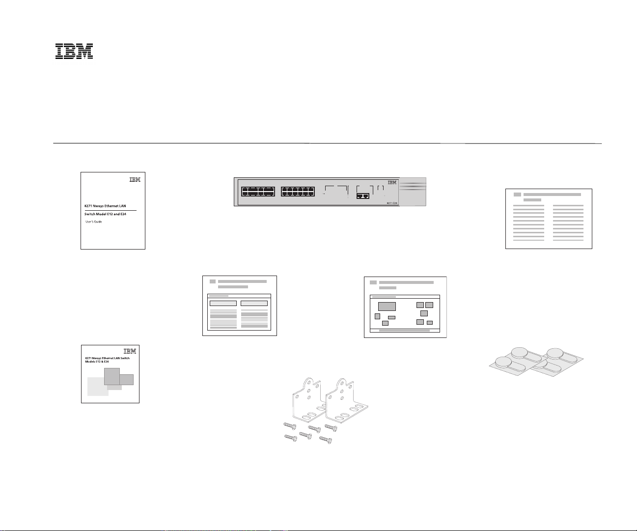
Package Contents
User’s Guide
Version 1.0
M
ODELS
Q
UICK INSTALLATION
E12
1x
13x
AND
green
6x 7x
18x 19x
12x
flashinggreen
TCVR
5
334
112
5
4
2
131314
17
151516
24x
14
17
16
8271 Model E12 (02L0876)
8271 Model E24 (02L0877)
Quick Reference Guide
E24
G
Status
=enabled,linkOK
=disabled,linkOK
off
=linkfail
667788991010111112
18181919202021212222232324
Module
Packet
12
Status
24
Status
Unit
10BASE-T/100BASE-TX
2
1
3
4
6
5
Power/Self test
25 26 PacketPacket
8
7
25 26 Status
25x 26x
Quick Installation Guide
UIDE
Release Notes
CD-ROM
4 x rubber feet
2 x mounting brackets and 6 x fixing screws
Page 2
Installing the Switch
DANGER: SD21-0030.
The User’s Guide also contains further information
on the following steps.
Powering-up the Switch
1
Plug the power cord into the power socket at the rear
of the Switch.
2
Plug the other end of the power cord into your power
outlet.
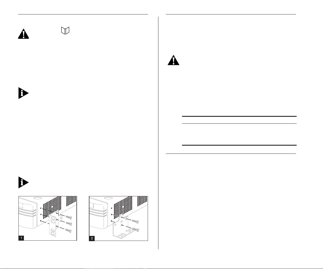
Installing into a 19-inch Rack
Fit the brackets as shown in 1 to each side of the unit.
Following the manufacturer’s instructions, secure the
unit into the rack.
You must use the screws supplied with the mounting
brackets. Damage caused to the unit by using incorrect
screws will invalidate your warranty.
Installing on a Wall
Place the Switch the right way up on a hard flat surface, with the front panel facing towards you. Fit the
brackets as shown in 2 to each side of the unit. Ensure
that the wall you are using is smooth, flat, dry and
sturdy. Attach a piece of plywood securely to the wall
if necessary. Position the base of the Switch against the
wall, ensuring that the ventilation holes face sidewards
and the front panel faces upwards. Secure using suitable screws and fixings (not provided).
You must use the screws supplied with the mounting
brackets. Damage caused to the unit by using incorrect
screws will invalidate your warranty.
DANGER:
It is essential that the mains socket
outlet is installed near to the unit and is accessible. You can only disconnect the unit by removing
the appliance coupler from the unit.
The Switch powers-up and runs through its Power On
Self Test (POST), which takes approximately 12 seconds. When the POST is complete, check the
Power/Self Test LED to see that your Switch is operating correctly.
Color State
Green The Switch is powered-up and operating normally.
Yellow The Switch has failed its POST.
Off The Switch is not receiving power.
Further Information
You can find further information about installing and
powering-up the Switch in the
Ethernet LAN Switch Model E12 and E24 User’s
Guide”
, Part Number 02L0884
IBM 8271 Nways
“
Part Number: 02L0885
Published: July, 1998
 Loading...