

Page 1

WebSphere
Version 6.2
®
IBM WebSphere Partner Gateway Enterprise and Advanced Editions
Administration Guide
Page 2

Note
Before using this information and the product it supports, read the information in “Notices” on page 253.
April 2010
This edition applies to version 6.2, release 0, modification 0 of IBM WebSphere Partner Gateway Enterprise Edition
(product number 5724-L69) and version 6.2, release 0, modification 0 of Advanced Edition (product number
5724-L68) and to all subsequent releases and modifications until otherwise indicated in new editions.
When you send information to IBM, you grant IBM a nonexclusive right to use or distribute the information in any
way it believes appropriate without incurring any obligation to you.
© Copyright International Business Machines Corporation 2007, 2008.
US Government Users Restricted Rights – Use, duplication or disclosure restricted by GSA ADP Schedule Contract
with IBM Corp.
Page 3

Contents
Chapter 1. About this book ......1
Audience ...............1
Roles, access levels, and responsibilities .....1
Typographic conventions ..........2
Related documents ............3
New in release 6.2 ............3
Chapter 2. Managing the WebSphere
Partner Gateway component
applications .............5
Managing WebSphere Partner Gateway components
in a simple mode system ..........5
Managing WebSphere Partner Gateway components
in a distributed mode system .........6
The Deployment Manager ..........7
Starting and stopping servers from the command
line ................8
Starting and stopping FTP Management Server
from command line ...........8
Starting and stopping the components in a simple
distributed mode system .........9
Starting servers in a simple distributed mode
system ...............9
Stopping servers in a simple distributed mode
system ...............10
Starting and stopping the components in a full
distributed mode system .........11
Starting servers in a full distributed mode system 11
Stopping servers in a full distributed mode
system ...............12
Chapter 3. Basic Community Console
tasks ...............15
Logging in to the Community Console .....15
Navigating through the Community Console . . . 16
Community Console icons .........16
Logging off from the Community Console ....18
Chapter 4. Hub administration tasks . . 19
Managing password policy .........19
Changing database connectivity, database user and
password ...............20
Managing event codes ...........20
Viewing and editing event codes ......21
Exporting event code names ........21
Specifying events that can be notified ....22
Document Validation Errors .........22
Managing receivers ............22
Viewing and editing receiver details .....22
Enabling or disabling receivers .......22
Deleting receivers ...........23
Localizing HTTP synchronous target time out . . . 23
Managing interactions and document definitions . . 23
Managing XML formats ..........24
Large file support ...........25
Enabling or disabling actions ........25
Managing handlers ............25
Importing a handler ..........26
Deleting a handler ...........26
Configuring the content-type attribute in
handlers ..............26
Managing maps .............27
Updating validation maps ........27
Viewing validation maps Where used ....27
Deleting validation maps .........27
Managing transformation maps.......27
Managing EDI FA maps .........28
Managing EDI .............28
Envelope profile ............28
Enveloper ..............29
Connection profiles ...........30
Control number initialization .......30
Current control numbers .........31
Managing system configuration data .....32
Configuring the alert mail server .......33
Viewing system activity ..........33
Managing event delivery ..........34
Managing API calls............34
Managing Document Manager information ....35
Maximum hold time ..........35
Maximum files-per-poll-interval ......35
Supporting ebMS ............36
Uploading a CPA to WebSphere Partner Gateway 36
Non-prepopulated attributes........37
Algorithms supported by the ebMS .....38
Configuration details for validating Webservices . . 38
Using non-repudiation logging ........39
Using message store ...........39
Prerequisite to setup WebSphere Partner Gateway WebSphere Transformation Extender Integration
Environment ..............40
Chapter 5. Account administration
tasks ...............41
Managing partner profiles .........41
Viewing and editing partner profiles .....41
Searching for partners ..........41
Deleting partners ...........42
Managing destination configurations ......42
Required information for destination
configuration .............42
Viewing and editing destinations ......43
Viewing and editing default destination ....45
Viewing destination Where used ......45
Deleting destination ..........45
Uploading transports ..........46
Deleting transports ...........46
Transport and destination retries ......46
Forward proxy support .........49
© Copyright IBM Corp. 2007, 2008 iii
Page 4

Managing certificates ...........49
Configuring the certpath related properties . . . 51
Viewing and editing digital certificates ....52
Disabling a digital certificate .......53
Changing B2B attribute values ........53
Managing partner connections ........54
Connection components .........54
Connection duplication .........55
Searching for connections.........55
Changing connection configurations .....57
Managing exclusion lists ..........58
Adding partners to the exclusion list .....59
Editing the exclusion list .........59
Chapter 6. Administering partner
migration..............61
Using the migration utility from the command line 61
Invoking from the command line ......63
Mapping of XML element with Console .....65
Exporting partner migration .........67
Considerations when creating your own import data 69
Manual validation of the import file .....69
Migration configuration type dependencies . . . 69
Export/Import order ..........72
BCG and DIS Import ...........73
Non-migratable configurations ........73
Limitations of the migration utilities .....73
Forward proxy migration.........73
Chapter 7. LDAP support for logon
authentication ...........75
Using LDAP ..............75
Enabling the container managed authentication
mechanism ..............75
Enabling J2EE security..........75
User names and groups .........76
Stopping the use of LDAP authentication ....76
Sample LDAP configuration .........77
Configuring the WebSphere Application Server
for the standalone IBM Tivoli Directory Server . 77
Specifying LDAP users to use the WebSphere
Partner Gateway Console.........79
Chapter 8. Support for IPv6 ......81
Enabling tunneling IPv6 over IPv4.......81
RHEL Linux 3 ............81
Windows 2003/XP ...........81
HP-UX 11i ..............82
Enabling IPV6 .............82
Configuring attributes ...........83
Chapter 10. Analyzing document flows 89
Document Analysis tool ..........89
Viewing the state of documents in the system . . 90
Viewing documents in the system ......90
Viewing process and event details ......91
Document Volume Report .........91
Creating a Document Volume Report .....91
Exporting the Document Volume Report....92
Printing reports ............92
Test Partner Connection ..........92
Pinging ebMS partners .........93
Web Server result codes .........93
EDI Reports ..............96
EDI FA Overdue Search .........96
EDI Rejected Transaction Search ......97
FTP Reports ..............99
FTP Statistics .............99
FTP Connections ...........99
Chapter 11. Viewing events and
documents ............101
Event Viewer .............101
Event types .............102
Searching for events ..........102
Viewing event details..........103
Error events .............103
AS Viewer ..............104
Searching for messages .........105
Viewing message details.........106
RosettaNet Viewer............107
Searching for RosettaNet processes .....107
Viewing RosettaNet process details .....108
Viewing raw documents .........109
Document Viewer ............109
Searching for documents ........109
Viewing document details, events, and raw
documents .............111
Mass document resend .........112
Viewing EDI documents .........113
Document Validation Errors .......114
Viewing data validation errors.......115
Stopping a document that is in process ....116
Re-sending failed and successful documents . . 116
ebMS Viewer .............118
Searching for ebMS processes .......118
Viewing ebMS process details .......119
Viewing raw documents .........119
Requesting and viewing the status of a
document .............120
Destination Queue............120
Chapter 9. Managing the Destination
Queue ...............85
Viewing the Destination Queue........85
Viewing queued documents .........86
Stopping the processing of documents from the
destination queue ............87
Viewing destination details .........88
Changing destination status .........88
iv IBM WebSphere Partner Gateway Enterprise and Advanced Editions: Administration Guide
Chapter 12. Simulating production
traffic ...............121
Preparing to test ............122
Setting up test scenarios ..........122
Sample scenarios ...........123
Uploading and viewing your requests and
responses...............125
Initiating and viewing document type .....125
Searching for an open document ......126
Page 5

Responding to an open document .....126
Removing an open document .......127
Chapter 13. Archiving ........129
Archiver configuration ..........129
View archiver task...........129
Archiver task modification ........131
Export and Import of archiver configuration . . 132
Archiver runtime tasks ..........132
Archiver reports ............133
Archiver Restore ............135
Restoring archived data of WebSphere Partner
Gateway V6.1 and earlier ........136
Searching the restored documents .....136
User intervention for archiving .......137
Archiver Restrictions ...........138
Chapter 14. Using logging and tracing
features ..............139
Log and trace files ............139
Log file management ...........140
Trace file management ..........141
Configuring tracing in a simple mode system 142
Setting tracing in a distributed mode system 142
Tracing tasks common to both types of systems 143
Setting log detail levels .........144
Identifying WebSphere Partner Gateway trace
messages ..............145
EDI, XML, ROD subcomponent tracing.....145
Interpreting WebSphere Application Server log and
trace messages .............146
WebSphere Application Server event types . . 146
Integrated FTP Server logging ........146
Chapter 15. FTP Server Configuration
Management............149
FTP user management ..........150
Chapter 16. Relocation and
Redeployment of WebSphere Partner
Gateway .............151
Prerequisites..............151
Restoring the configuration details .....152
Changing host name and IP address of WebSphere
Partner Gateway ............152
Changing the host name and port number of
database ...............153
Changing the port numbers ........153
Relocation and redeployment examples.....154
Chapter 17. Troubleshooting .....157
Avoiding long processing time on large encrypted
AS documents .............158
Avoiding long processing time for large encrypted
documents ..............159
Avoiding out-of-memory errors .......159
Document Manager memory configuration . . 159
Document Manager workload .......160
Document structure ..........160
Increasing the heap size .........160
Collating data for multiple languages .....160
Ensuring sufficient virtual memory for DB2 agents 161
Fixing DB2 SQL errors ..........161
SQLCODE -444 error ..........162
SQLCODE -289 error ..........162
SQLCODE -1225 error .........162
SQL 0964C Transaction log full error on the
BCGMAS database ..........162
IBM service log unreadable .........163
WebSphere Application Server informational
messages ...............163
Increasing the Receiver timeout setting .....163
Optimizing database query performance ....164
Resolving event 210031 ..........164
Documents routed twice when network is lost or
document manager server shutdown abruptly . . 165
0A1 generated with data validation errors....165
EDI reports export the first 1000 records only . . 165
Console does not start after a server restart . . . 165
FTPScripting Receiver receives
StringIndexOutofBoundsException ......166
Error scenario ............166
Working scenario ...........166
Receiver Failure to read Configuration File . . . 166
Configuring Users to receiving Alerts Notification 166
Resolving ClassNotFoundException for User Exit
classes................167
Reprocessing events and business documents that
fail to log to the database .........167
Disabling JIT in a WebSphere Application Server
when WebSphere Partner Gateway produces a
javacore ...............168
Defining a custom transport type.......168
Resolving WebSphere Partner Gateway errors
BCG210031 and BCG240415 ........168
Creating File directory destination on a drive other
than C: ...............169
Preventing partner transactions from being
processed by WebSphere Partner Gateway....169
Fixing the browser ERROR: 500 .......170
Downloading CRL for SSL transactions .....170
Databinding in JMS Exports/Imports within
WebSphere Process Server .........171
Fixing test partner connection for SSL connections 172
Fixing errors BCGEDIEV0O56 and BCG210001 . . 172
Fixing ORA-00988 error ..........172
Configuring Content-Types attribute for the fixed
workflow handlers ...........172
Fixing BCG210013 error ..........173
Increasing buffer size to prevent document
transmission low performance........174
WebSphere Partner Gateway hub installer logs
error messages .............174
DB password required error in bcgHubInstall.log 175
Using revocation check and using CRL DP support 175
Returning document volume report search
information about the console ........175
Loading the native library .........176
Fixing error TCPC0003E and CHFW0029E ....176
CA certificate expiration ..........177
Contents v
Page 6

VCBaseException in the SystemOut.log .....178
Reporting file size for documents greater than
2GB................178
SSL handshake fails because no certificate received 178
Fixing the hanging threads warning ......179
Stopping the Document Manager exception . . . 179
Fixing WebSphere MQ messages .......180
MQJMS2007 error ...........180
MQJMS2013 error ...........181
java.security.InvalidKeyException: Illegal key size
or default parameter ...........181
The MDN status of ’unknown’ for AS transactions 181
Servers fail to start after applying fixes .....181
Correcting the shortcut ports for WebSphere
Application Server ...........182
Avoiding duplicate document delivery when there
is more than one router ..........182
Rendering of tab headings on displays with
resolution greater than 1024 ........183
Documents not processed when using Oracle 9i
Release 2 ...............183
Document processing when the database goes
down ................183
java.lang.NoClassDefFoundError with
reprocessDbLoggingErrors.bat ........184
Recovery process when queue and disk is full or
unavailable ..............184
Workflow Handler Runtime Error ......184
Error while invoking WebSphere Transformation
Extender Map .............185
IBM Support Assistant (ISA) Plugin ......185
Partner Migration Utility with LDAP .....185
AS signature failure for interop content type . . . 186
Appendix A - performance
considerations ...........187
Managing queue overflow .........187
Generating summary data .........187
Appendix B - failed events......189
Appendix C - component-specific
system attributes..........223
Configuring attributes as WebSphere Application
Server ND environment variables ......223
Editing RosettaNet attribute values ......223
Editing FTP Administration .......224
Attribute tables .............228
Notices ..............253
Programming interface information ......255
Trademarks and service marks .......255
Index ...............257
vi
IBM WebSphere Partner Gateway Enterprise and Advanced Editions: Administration Guide
Page 7

Chapter 1. About this book
This document describes how WebSphere Partner Gateway can be maintained to
suit the requirements of the business-to-business (B2B) trading community. This
guide assumes that you have already performed the necessary hub configuration
tasks provided in the WebSphere Partner Gateway Hub Configuration Guide.
Audience
Administrators maintain WebSphere Partner Gateway. This book assumes two
types of administrators:
v Hub administrator: is the super user in the community. The hub administrator is
responsible for overall hub community configuration and management,
including partner configuration and connection activation.
v Account administrator: has access to a subset of the hub administrator features
and is the main administrative user for the internal partner or external partner.
v Internal Partner: is the primary company and driving force within the hub
community. Internal partner is responsible for the purchase and creation of the
hub community. In addition, the internal partner provides the definition of the
electronic business process transactions that happen between them and their
external partners.
v External Partner: is the company that does business with the internal partner
through the hub community. External partners have to complete a configuration
process to connect to the hub community. Once connected, external partners can
exchange electronic business documents with the internal partner.
Refer to WebSphere Partner Gateway Partner Guide for more information on hub
administrator, internal partner, and external partner.
Roles, access levels, and responsibilities
In WebSphere Partner Gateway, the hub administrator sets up the profiles of the
partners. A partner always has at least one administrator user and can have
additional users added by the administrator of that profile.
To illustrate the concept of roles, a simple implementation of WebSphere Partner
Gateway with a minimum of three profiles is described as follows:
Hub Operator
This is a system defined profile that will be included on the machine during
installation. The Hub Operator profile has one defined user name, hubadmin,
which is the super-user of the system and can accomplish any configuration task.
You can relate this role to the IT group that runs the actual WebSphere Partner
Gateway server, but is not actively sending documents back and forth. There can
be only one Hub Operator type participant.
Internal Partner
This partner is created by the hubadmin user. This user is the company that
bought the WebSphere Partner Gateway and is running the system. There can be
many internal partners, but only one default internal partner. Businesses act as
© Copyright IBM Corp. 2007, 2008 1
Page 8

both Hub Operator and internal partner if they do not delegate the task of
configuring and monitoring the WebSphere Partner Gateway system to some
internal IT group or a third-party company.
External Partner
This is the partner with which the internal partner communicates. There can be
multiple partners of this type. If the partner has its own implementation of
WebSphere Partner Gateway, then it becomes the internal partner on its own
system and a external partner on this one.
Each of these profiles has at least one user ID. As mentioned above, Hub Operator
profile is the hubadmin super-user of the system. The other two profiles will each
have an admin user assigned to them upon initial creation. These users, in turn,
can create other users with equal or less abilities. Each of these admin users has
certain configuration abilities. For example, the hubadmin user can create any
object on the system such as the internal partner or load system-wide security
certificates. The internal partner role can create participants or connections. The
external partner role is the most limited in scope and can view its own documents
and configure the local destinations to which the internal partner has to deliver
documents.
Typographic conventions
This document uses the following conventions.
Table 1. Typographic conventions
Convention Description
Monospace font Text in this font indicates text that you type, values for
arguments or command options, examples and code
examples, or information that the system prints on the
screen (message text or prompts).
bold Boldface text indicates graphical user interface controls (for
example, online button names, menu names, or menu
options) and column headings in tables and text.
italics Text in italics indicates emphasis, book titles, new terms
and terms that are defined in the text, variable names, or
letters of the alphabet used as letters.
Italic monospace font Text in italic monospace font indicates variable names
within monospace-font text.
ProductDir ProductDir represents the directory where the product is
installed. All IBM WebSphere Partner Gateway product
path names are relative to the directory where the IBM
WebSphere Partner Gateway product is installed on your
system.
%text% and $text Text within percent signs (%) indicates the value of the
Windows
equivalent notation in a UNIX
indicating the value of the text UNIX environment variable.
Underlined colored text Underlined colored text indicates a cross-reference. Click the
text to go to the object of the reference.
(R)
text system variable or user variable. The
(R)
environment is $text,
2 IBM WebSphere Partner Gateway Enterprise and Advanced Editions: Administration Guide
Page 9

Table 1. Typographic conventions (continued)
Convention Description
Text in a blue outline (In PDF files only) An outline around text indicates a
“ ” (quotation marks) (In PDF files only) Quotation marks surround
{} In a syntax line, curly braces surround a set of options from
[] In a syntax line, square brackets surround optional
<> Angle brackets surround variable elements of a name to
/ or \ Backslashes (\) are used as separators in directory paths in
Related documents
cross-reference. Click the outlined text to go to the object of
the reference. This convention is the equivalent for PDF files
of the “Underlined colored text” convention included in this
table.
cross-references to other sections of the document.
which you must choose one and only one.
parameters.
distinguish them from one another. For example,
<server_name><connector_name>tmp.log.
Windows installations. For UNIX installations, substitute
slashes (/) for backslashes.
The complete set of documentation available with this product includes
comprehensive information about installing, configuring, administering, and using
WebSphere Partner Gateway Enterprise and Advanced Editions.
You can download the documentation or read it directly online at the following
site:
http://www.ibm.com/software/integration/wspartnergateway/library/
Note: Refer to Technical Support Technotes and Flashes in WebSphere Partner
Gateway Support Web site for the latest information about this product.
Access
http://www.ibm.com/software/integration/wspartnergateway/support/ and
select the component area of interest.
New in release 6.2
WebSphere Partner Gateway V6.2 supports the following new features:
v Integration with WebSphere Transformation Extender using WebSphere Partner
Gateway’s extensibility framework
v ISA V4 support for log file collection and transmission
v Certificate upload and configuration enhancements
v Links to error messages with message details
v WebSphere Partner Gateway First Steps page enhancements
v Scripts to update WebSphere Partner Gateway settings for relocation and
redeployment
Chapter 1. About this book 3
Page 10

v Ability to run installation verification test (IVT) at the end of WebSphere Partner
Gateway component installation
v Ability to export and import complete WebSphere Partner Gateway
configuration
v Support for auto-upgrade to minimize manual upgrade effort
v Console based archiver with scheduler
v Ability to federate into an existing WebSphere Application Server cell
v Support for Secure File Transfer Protocol (SFTP)
v CPP/CPA Editor for ebXML Message Service (ebMS)
v Enhancements
– Improved archiver performance
– Improved document throughput performance for AS2 and large files
For more details about the new 6.2 features, see http://www-01.ibm.com/
software/integration/wspartnergateway/about/
4 IBM WebSphere Partner Gateway Enterprise and Advanced Editions: Administration Guide
Page 11

Chapter 2. Managing the WebSphere Partner Gateway
component applications
Managing the WebSphere Partner Gateway component applications means starting,
stopping, and configuring the application servers that host the WebSphere Partner
Gateway components. These administrative tasks generally involve using
WebSphere Application Server interfaces that control and configure a set of
application servers where the WebSphere Partner Gateway components are
deployed by the installation process.
How you manage the WebSphere Partner Gateway component applications
depends on whether the product was installed using a simple topology or a
distributed topology. In this document, the terms simple mode and distributed
mode are used to refer to the topology chosen during product installation.
Note: See the WebSphere Partner Gateway Installation Guide for details on simple and
distributed topologies.
The administrator managing WebSphere Partner Gateway components is aware of
the mode of installation (simple or distributed).
In a simple mode installation, the WebSphere Partner Gateway components are all
installed on the same computer using one application server called server1.As
simple mode system does not use Deployment Manager, the mechanics of starting
and stopping the WebSphere Partner Gateway components are similar to usage of
WebSphere Application Server base (rather than network deployment).
All the computers can have WebSphere Application Server installed, but only the
Deployment Manager requires the installation of WebSphere Application Server
Network Deployment.
The application servers hosting the WebSphere Partner Gateway components are
all logically contained in a Deployment Manager cell that is administered using the
Deployment Manager application. However, the distinction is hidden when you
use the Deployment Manager for administration tasks. The Deployment Manager
console provides a view of the distributed WebSphere Partner Gateway component
applications that hides the details about where they are installed.
Managing WebSphere Partner Gateway components in a simple mode
system
For a simple mode system, it is necessary to know how to start and stop the
application server that hosts all of the WebSphere Partner Gateway components.
To start the WebSphere Partner Gateway components, run one of the following
scripts:
v UNIX
v Windows
(R)
<install dir>/bin/bcgStartServer.sh
(R)
<install dir>\bin\bcgStartServer.bat
© Copyright IBM Corp. 2007, 2008 5
Page 12

To stop the WebSphere Partner Gateway components, run one of the following
scripts:
Note: You do not have to specify a server name. The server name is always
server1 when simple mode is used.
v UNIX
v Windows
(R)
<install dir>/bin/bcgStopServer.sh
(R)
<install dir>\bin\bcgStopServer.bat
Managing WebSphere Partner Gateway components in a distributed
mode system
For a distributed mode system, the WebSphere Deployment Manager application is
used to control all of the WebSphere Partner Gateway applications. One of the
computers in the distributed mode system is chosen during installation to host the
Deployment Manager. When the WebSphere Partner Gateway applications are
installed, the application server or servers that they are installed on are placed
under control of the Deployment Manager. As the system administrator, you
manage the WebSphere Partner Gateway components by using the Deployment
Manager. This provides a single point of access to all the components, even if they
are on different computers.
See the WebSphere Application Server Network Deployment product
documentation for a detailed description of the way that a Deployment Manager is
used to administer application servers. For purposes of this document, there are
some terms and concepts regarding the way that the Deployment Manager
operates.
Distributed topology terms and concepts
v The system consists of one or more nodes.
v The WebSphere Deployment Manager is an application that runs on one of the
nodes in the system.
v The WebSphere Partner Gateway components (console, receiver, and router) are
installed on application servers on the nodes in the system.
v The default messaging support of WebSphere Application Server is used, so
bcgmas server contains the message queues required by WebSphere Partner
Gateway for its internal messaging support.
v Each node that hosts WebSphere Partner Gateway components has a special
application called the node agent. The node agent provides a connection
between the application servers on the node and the Deployment Manager
application.
v The nodes are combined into a logical grouping called a cell. The Deployment
Manager provides you with a view of the cell from which you can manage the
applications in the system.
v The application servers on the nodes within the cell are organized into clusters.
All the application servers in a cluster have the same WebSphere Partner
Gateway components.
v The cell is administered by the central WebSphere Deployment Manager. This
means that:
– All the servers within the cell can be started, stopped, and modified from the
Deployment Manager.
6 IBM WebSphere Partner Gateway Enterprise and Advanced Editions: Administration Guide
Page 13

– The internal messaging can be managed from the Deployment Manager.
v There are two variations on distributed mode called simple distributed mode
and full distributed mode.
– In simple distributed mode all three WebSphere Partner Gateway components
are part of the same cluster. This also includes a cluster of bcgmas server.
– In full distributed mode each component is typically in its own cluster, for
example the console is in a bcgconsole cluster, receiver in a bcgreceiver
cluster, and the document manager in a bcgdocmgr cluster. In addition there is
a messaging bcgmas cluster used for internal communication between the
WebSphere Partner Gateway components.
The Deployment Manager
The role of the Deployment Manager is to give you a single view of all of the
application servers in the cell from which you can administer the servers. To
achieve this, a node agent has to be running on each node that hosts WebSphere
Partner Gateway components. The Deployment Manager uses the node agents to
interact with the application servers in the system. During a distributed mode
installation, for each node in the system a node agent is installed and configured to
communicate with the Deployment Manager.
You use the Deployment Manager’s web interface to manage the applications that
are in the cell. If for some reason the Deployment Manager is not available then
the WebSphere Partner Gateway components can be manually started or stopped
from the command line, but other administration tasks cannot be performed until
the Deployment Manager is available again.
The most common administration task that is performed is starting and stopping
the WebSphere Partner Gateway components. Other administration tasks like
configuring a server for logging and tracing or changing the startup parameters for
the Java Virtual Machine used by a server can also be performed with the
Deployment Manager.
To use the Deployment Manager:
1. Start the node agent on each node that hosts WebSphere Partner Gateway
applications and the node where the bcgmas server is installed. To start the
node agent on a computer use the WebSphere startNode script with no
arguments. This script is located in the <WebSphere Partner Gateway install
dir>/wasND/Profiles/bcgprofile/bin directory.
2. Start the Deployment Manager. To start the Deployment Manager use the
WebSphere Partner Gateway bcgStartServer script with no arguments. This
script is located in the <Deployment Manager install dir>\bin directory.
3. Open an appropriate Internet browser.
4. Navigate to http://<computer name or IP address of the Deployment
Manager>:55090/ibm/console to open the WebSphere Integrated Solutions
Console Welcome login screen, and log in.
Note: A user id is not required for logging in. On the left side of the Welcome
screen you will see a list of tasks that can be done from this console.
5. To start or to stop all servers in a cluster:
v In the left pane click Clusters
v In the right pane, select the cluster to start or stop.
v Click start or stop
Chapter 2. Managing the WebSphere Partner Gateway component applications 7
Page 14

Note: This operation may take a few minutes. You can refresh the view
periodically to see the status.
6. To start or to stop individual servers:
a. In the left pane click Application Servers
b. In the right pane, select the server for the node to start or stop.
Note: Remember that a node represents an instance of WebSphere
Application Server deployed on a computer in your system.
c. Click start or stop.
Starting and stopping servers from the command line
About this task
When the Deployment Manager is not available, the WebSphere Partner Gateway
components in a distributed mode system can be manually started and stopped on
the individual computers. General administration tasks, for example changing
log/trace settings, cannot be performed unless the Deployment Manager is
available.
To use the command line scripts:
1. Start the node agent on each node that hosts WebSphere Partner Gateway
applications and the node where the bcgmas server is installed. To start the
node agent on a computer, use the WebSphere startNode script with no
arguments. This script is located in the WebSphere Partner Gateway Install
Dir/wasND/Profiles/bcgprofile/bin directory.
2. Start each WebSphere Partner Gateway server by running the startServer
script located in the <WebSphere Parnter Gateway Install Dir>/wasND/
Profiles/bcgprofile/bin directory on the computer where the server was
installed. The syntax is:
startServer <server_name>
Where the server_name is bcgconsole,bcgreceiver, bcgdocmgr or bcgmas.
3. Stop each WebSphere Partner Gateway server by running the stopServer script
located in the WebSphere Partner Gateway Install Dir/wasND/Profiles/
bcgprofile/bin directory on the computer where the server was installed.
The syntax is:
stopServer <server_name>
Where the server_name is bcgconsole,bcgreceiver, bcgdocmgr or bcgmas.
Starting and stopping FTP Management Server from command
line
The FTP Management server must be running to manage the FTP server from
WebSphere Partner Gateway console. To start the FTP Management server on a
computer, use the startftpmgmtserver script. This script is located at WebSphere
Partner Gateway Install Dir/ftpserver/bin. This script does not require any
command line arguments. The Integrated FTP Server is started implicitly when the
FTP Management server starts.
To Stop the FTP Management server on a computer, use stopftpmgmtserver script.
This script is located in the WPG Install Dir/ftpserver/bin. This script does not
8 IBM WebSphere Partner Gateway Enterprise and Advanced Editions: Administration Guide
Page 15

require any command line arguments. The Integrated FTP Server is stopped
implicitly when the FTP Management server stops.
Note: This is applicable for all deployment modes.
Starting and stopping the components in a simple distributed
mode system
There are two clusters in a simple distributed mode system:
bcgmasCluster
The messaging cluster that has messaging servers. There has to be at least
one messaging server running for the WebSphere Partner Gateway
components to operate.
bcgserverCluster
The WebSphere Partner Gateway component cluster that has servers
named bcgserver. All three components (console, receiver and router) are
installed on the bcgserver.
The names shown here are default names used by the installer. Be aware that the
installer might have chosen different names and that you must use these names if
the default names were not used.
Starting servers in a simple distributed mode system
Before starting your server in a simple distributed mode system, start the
messaging servers prior to starting the WebSphere Partner Gateway component
servers.
Starting all the servers using the Deployment Manager
About this task
1. Confirm that the node agent is running for each node with the bcgmas server
and the bcgserver installed.
2. Using the Deployment Manager console, select the messaging cluster
bcgmasCluster and click Start.
3. Wait for the bcgmasCluster to start before performing the next step.
4. Select the bcgserverCluster and click Start.
Starting individual servers on each computer
About this task
1. Confirm that the node agent(s) are running for each node with the bcgmas
server and the bcgserver installed.
2. Select the messaging bcgmas server and click Start.
3. Repeat the previous step starting all of the other bcgmas servers.
Note: Wait until at least one of the messaging servers has started before
starting the WebSphere Partner Gateway component servers.
4. Select the bcgserver server and click Start.
5. Repeat step 4 to start all of the required component servers. A cluster can
contain more than one server. You can select any of the servers in the cluster,
and start them.
Chapter 2. Managing the WebSphere Partner Gateway component applications 9
Page 16

Starting the servers when the Deployment Manager is
unavailable
About this task
If the Deployment Manager is unavailable for use, you can Start the messaging
bcgmas and the bcgserver servers manually with the following steps:
1. Confirm that the node agents are running for each node with the bcgmas server
and the bcgserver installed.
2. Start each WebSphere Partner Gateway server by running the startServer
script located in the <WebSphere Install Dir>/wasND/Profiles/bcgprofile/bin
directory on the computer where the server is installed.
The syntax is for starting the messaging server, console, receiver, or Document
Manager for the component servers is:
startServer <server_name>
Where server_name is bcgmas for starting the messaging server, and bcgserver
for the component servers.
Stopping servers in a simple distributed mode system
When stopping servers in a simple distributed mode system stop the WebSphere
Partner Gateway component servers before stopping the messaging servers.
Stopping all the servers using the Deployment Manager
About this task
1. Select the bcgserverCluster and click Stop. Wait for the cluster to stop before
performing the next step.
2. Select the messaging cluster bcgmasCluster and click Stop.
Stopping the individual servers on each computer
About this task
If you do not want to stop all servers in each cluster, you can stop the servers on
each computer where they are installed. To stop the servers on each computer,
perform the following steps:
1. Select the bcgserver server to stop and click Stop.
2. Repeat the previous step until you have stopped all of the servers you want to
stop. Wait for the servers to stop before performing the next step.
3. Select the bcgmas server messaging you want to stop and click Stop.
4. Repeat the previous step until you have stopped all of the servers. If any of the
bcgserver servers are still running then leave at least one bcgmas server
running.
Stopping the servers when the Deployment Manager is
unavailable
About this task
First, stop the bcgserver servers before the messaging bcgmas servers.
1. Confirm that the node agents are running for each node with the bcgmas server
and the bcgserver installed.
2. Stop each WebSphere Partner Gateway server by running the stopServer script
located in the <WebSphere Parnter Gateway Install Dir>/wasND/Profiles/
bcgprofile/bin directory on the computer where the server is installed.
10 IBM WebSphere Partner Gateway Enterprise and Advanced Editions: Administration Guide
Page 17

The syntax is for stopping the messaging server or bcgserver for the component
servers is:
stopServer <server_name>
Where server_name is bcgmas for stopping the messaging server, and bcgserver
for the component servers.
Starting and stopping the components in a full distributed
mode system
Before you begin, you must know that there are four clusters in full distributed
mode system. They are as follows:
v bcgmasCluster
The messaging cluster that has messaging servers named bcgmas. There must be
at least one messaging server running for the WebSphere Partner Gateway
components to operate.
v bcgconsoleCluster
The WebSphere Partner Gateway Console component cluster that has servers
named bcgconsole.
v bcgreceiverCluster
The WebSphere Partner Gateway Receiver component cluster that has servers
named bcgreceiver.
v bcgdocmgrCluster
The WebSphere Partner Gateway Document Manager component cluster that has
servers named bcgdocmgr.
The names shown here are the installation default names. Be aware that during
installation, the installer might have chosen different names and you must use
these names instead of the default names.
Starting servers in a full distributed mode system
To start your servers in a full distributed mode system, the startup sequence is as
follows:
1. Messaging servers
2. WebSphere Partner Gateway document manager servers
3. WebSphere Partner Gateway receiver servers (or console servers)
4. WebSphere Partner Gateway console servers (or receiver servers)
Note: The receiver and console servers can be started in either order.
Starting all the servers using the Deployment Manager
About this task
1. Select the messaging cluster bcgmasCluster and click Start.
Note: Wait until the cluster has started before starting the WebSphere Partner
Gateway component clusters.
2. Select the bcgdocmgrCluster and click Start.
3. Select the bcgreceiverCluster (or the bcgconsoleCluster) and click Start.
4. Select the bcgconsoleCluster (or the bcgreceiverCluster) and click Start.
Chapter 2. Managing the WebSphere Partner Gateway component applications 11
Page 18

Starting individual servers on each computer
About this task
1. Select the messaging bcgmas server to start and click Start.
Note: Wait until at least one of the servers has started before starting the
WebSphere Partner Gateway component servers.
2. Repeat the previous step until you have started all of the servers.
3. Select the bcgdocmgr server to start and click Start.
4. Repeat the previous step until you have started all of the servers.
5. Select the bcgreceiver (or bcgconsole) server to start and click Start.
6. Repeat the previous step until you have started all of the servers.
7. Select the bcgconsole (or bcgreceiver) server to start and click Start.
8. Repeat the previous step until you have started all of the servers.
Note: If more than one servers have to be started, then select those servers, and
click Start.
Starting the servers when the Deployment Manager is
unavailable
About this task
Note: Start the servers in the order shown in the previous section.
1. For each node with the bcgmas server and any of the WebSphere Partner
Gateway component servers installed make sure that the node agent(s) are
running.
2. Start each WebSphere Partner Gateway server by running the startServer
script located in the <WebSphere Partner Gateway Install Dir>/wasND/
Profiles/bcgprofile/bin directory on the computer where the server was
installed. The syntax is:
startServer <server name>
Where server name is bcgmas for starting the messaging server, bcgconsole,
bcgreceiver and bcgdocmgr for the component servers.
Note: Start bcgmas server first and then start the rest of the servers.
Note: Ensure that the user you use to start and stop the server is WPG user and is
not the root user.
Stopping servers in a full distributed mode system
It is important to note that the shutdown sequence is the opposite of the startup
sequence. It is as follows:
1. WebSphere Partner Gateway console (or receiver) servers.
2. WebSphere Partner Gateway receiver (or console) servers.
Note: The receiver and console servers can be stopped in either order.
3. WebSphere Partner Gateway document manager servers.
4. Messaging servers.
12 IBM WebSphere Partner Gateway Enterprise and Advanced Editions: Administration Guide
Page 19

Stopping all the servers using the Deployment Manager
About this task
1. Select the bcgconsoleCluster (or bcgreceiverCluster) and click Stop.
2. Select the bcgreceiverCluster (or bcgconsoleCluster) and click Stop.
3. Select the bcgdocmgrCluster and click Stop.
Note: Wait until the cluster has stopped before stopping the messaging cluster.
4. Select the messaging cluster bcgmasCluster and click Stop.
Stopping individual servers on each computer at a time
About this task
If you do not want to stop all servers in each cluster, you can stop the servers on
each computer where they are installed. To stop a server where it is installed,
perform the following steps:
1. Select the bcgconsole (or bcgreceiver) server to stop and click Stop.
2. Repeat the previous step until you have stopped all of the servers you want to
stop.
3. Select the bcgreceiver (or bcgconsole) server to stop and click Stop.
4. Repeat the previous step until you have stopped all of the servers yo want to
stop.
5. Select the bcgdocmgr server to stop and click Stop.
6. Repeat the previous step until you have stopped all the servers you want to
stop.
7. Wait until the servers have stopped before stopping the messaging servers.
8. Select the bcgmas server messaging you want to stop and click Stop.
9. Repeat the previous step until you have stopped all of the servers.
Note: If some of the WebSphere Partner Gateway component servers are still
running then keep at least one bcgmas server running.
Stopping the servers when the Deployment Manager is
unavailable
About this task
It is important to note that you must stop the WebSphere Partner Gateway servers
before the messaging bcgmas servers.
1. Confirm that for each node with the bcgmas server and any of the WebSphere
Partner Gateway component servers installed make sure that the node agent(s)
are running.
2. Stop each WebSphere Partner Gateway server by running the stopServer script
located in the <WebSphere Partner Gateway Install Dir>/wasND/Profiles/
bcgprofile/bin directory on the computer where the server was installed. The
syntax is:
stopServer <server_name>
Where server_name is bcgmas for stopping the messaging server, bcgconsole,
bcgreceiver and bcgdocmgr for the component servers.
Chapter 2. Managing the WebSphere Partner Gateway component applications 13
Page 20

14 IBM WebSphere Partner Gateway Enterprise and Advanced Editions: Administration Guide
Page 21

Chapter 3. Basic Community Console tasks
The tasks described in this guide are performed using the WebSphere Partner
Gateway Community Console. The Community Console is a Web application
providing a secure access point accessible through a web browser.
Topics covered in this chapter include:
v “ Logging in to the Community Console”
v “ Navigating through the Community Console” on page 16
v “Community Console icons” on page 16
v “ Logging off from the Community Console” on page 18
Logging in to the Community Console
The Community Console requires one of the following Web browsers:
(R)
v Microsoft
v Mozilla version 1.7.8 or later.
v Firefox version 1.5 or later.
Be sure to install the latest available service pack and updates for your browser.
Note: The Community Console requires cookie support to be turned on to
maintain session information. No personal information is stored in the cookie and
it expires when the browser is closed.
Internet Explorer version 6.0 with SP1 or 7.
For optimum viewing, use a minimum screen resolution of 1024 x 768.
To log in to the Community Console, follow these steps:
1. Type the following URL in the location field of any Web browser:
http://hostname.domain:58080/console (unsecure)
https://hostname.domain:58443/console (secure)
Where hostname and domain are the name and location of the computer hosting
the Community Console component.
2. In the Community Console login window, in the User Name field, type the
appropriate name:
v For the hub administrator, the default user name is hubadmin.
v For the operator administrator, the default user name is Admin.
3. In the Password field, type the password for your site. The default password is
Pa55word.
4. In the Company Login Name field, type the Admin login name. The default
login name for both the hub administrator and operator administrator user is
Operator
Note: If user IDs and passwords are going to be centrally managed from
Lightweight Directory Access Protocol (LDAP) then a Company Login Name
field will not display. For further information about LDAP see the section,
Chapter 7, “LDAP support for logon authentication,” on page 75.
5. Click Login.
© Copyright IBM Corp. 2007, 2008 15
Page 22
6. The first time you log in, the system prompts you to create a new password.
Type a new password, then type it again in the verify field.
7. Click Save.
Navigating through the Community Console
The Community Console consists of various menus used to configure WebSphere
Partner Gateway.
The following two links appear at the top-right corner of each window:
v Logout
Logs off the current WebSphere Partner Gateway session. The application
continues to run on the server. To log in again, follow the procedure under “
Logging in to the Community Console” on page 15.
v Help
Opens the online help for WebSphere Partner Gateway.
Note: If you do not see a help window after clicking help, check to make sure
you are not running a popup blocker.
Community Console icons
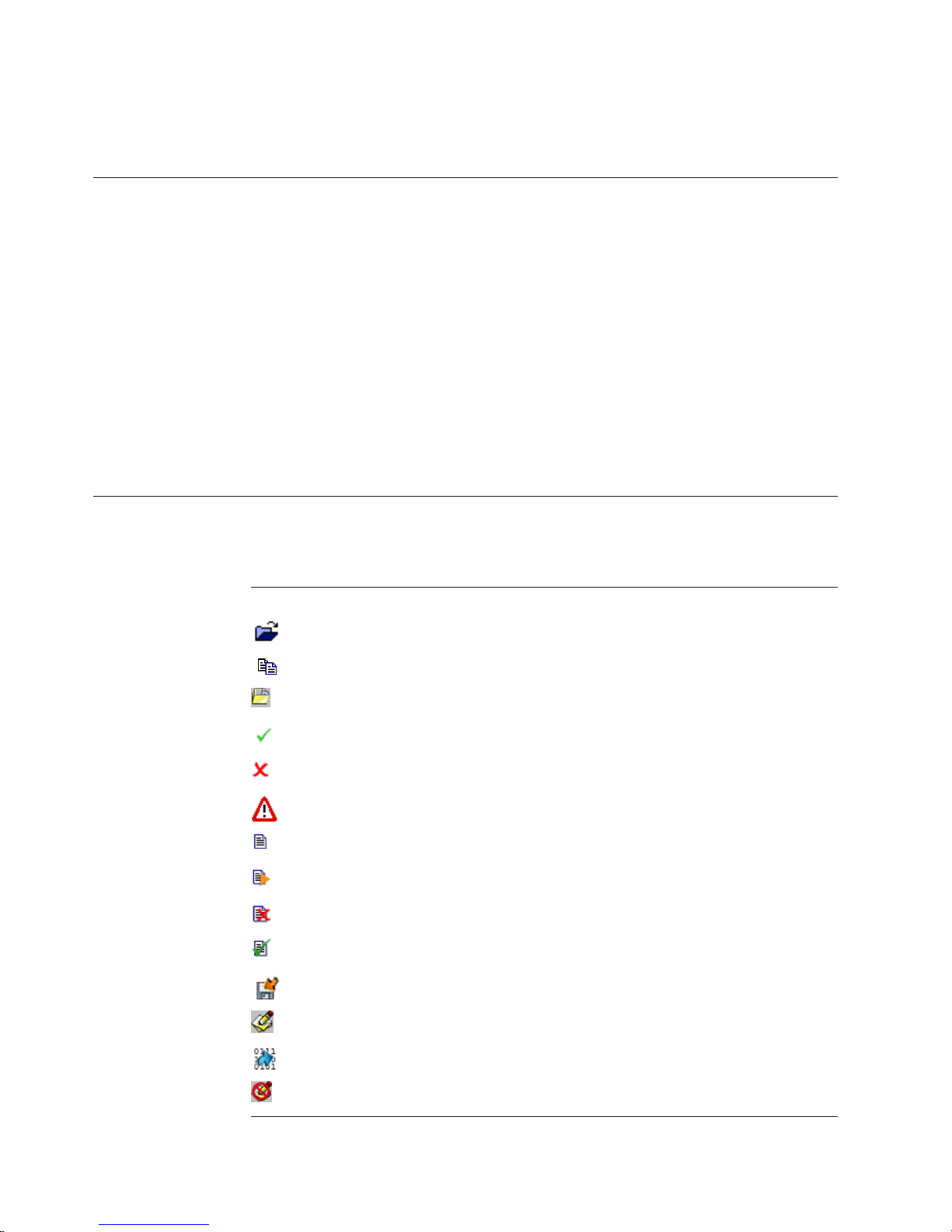
Table 2 lists the icons that are used throughout the Community Console windows.
Table 2. Community Console Icons
Icon Icon name
Collapse
Copy
Data contained
Activate
Delete
Destination disabled
Display raw document
Document in progress
Document processing failed
Document processing successful
Download map
16 IBM WebSphere Partner Gateway Enterprise and Advanced Editions: Administration Guide
Edit
Edit attribute values
Edit off
Page 23
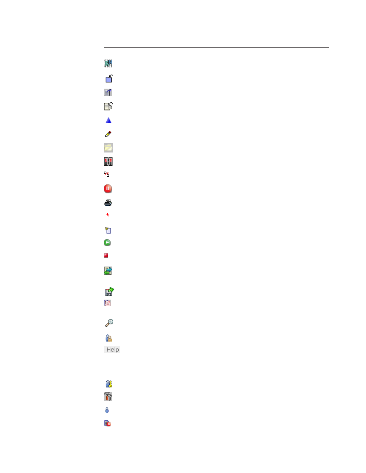
Table 2. Community Console Icons (continued)
Icon Icon name
Edit RosettaNet attribute values
Expand
Export information
Export report
Hide search criteria
Modify
No data contained
Open calendar
Out of sequence
Pause
Print
Required input
Role; click to create role
Start
Stop Submitted
Synchronous data flow. No icon is displayed for
asynchronous transactions
Upload map
View a previously sent original document when
there is a duplicate document event
View details
View group memberships
View Help system
Note: The Help icon is translated when using the
console with one of the IBM supported language
locales.
View permissions
View the Document Definition attribute setup
View users
View validation errors
Chapter 3. Basic Community Console tasks 17
Page 24

Table 2. Community Console Icons (continued)
Icon Icon name
Where used
Logging off from the Community Console
When you finish using the Community Console, click Logout at the top-right side
of any Console window. The system logs you out and returns you to the Console
Login window.
18 IBM WebSphere Partner Gateway Enterprise and Advanced Editions: Administration Guide
Page 25

Chapter 4. Hub administration tasks
This chapter describes the tasks that only a hub administrator can perform. These
tasks are:
v “Managing password policy”
v “Changing database connectivity, database user and password” on page 20
v “Managing event codes” on page 20
v “Managing receivers” on page 22
v “Managing interactions and document definitions” on page 23
v “Managing XML formats” on page 24
v “Enabling or disabling actions” on page 25
v “Managing handlers” on page 25
v “Managing maps” on page 27
v “Managing EDI” on page 28
v “Configuring the alert mail server” on page 33
v “Viewing system activity” on page 33
v “Managing event delivery” on page 34
v “Managing API calls” on page 34
v “Supporting ebMS” on page 36
v “Configuration details for validating Webservices” on page 38
v “Using non-repudiation logging” on page 39
v “Using message store” on page 39
v “Prerequisite to setup WebSphere Partner Gateway - WebSphere Transformation
Extender Integration Environment” on page 40
Managing password policy
You can set up a password policy for the hub community, if you want to use
values other than those set (by the system) as defaults. The password policy
applies to all users who log in to the Community Console.
You can change the following elements of the password policy:
v Minimum Length, which represents the minimum number of characters the
partner has to use for the password. The default is 8 characters.
v Expire Time, which represents the number of days until the password expires.
The default is 30 days.
v Uniqueness, which specifies the number of passwords to be held in a history
file. A partner cannot use an old password if it exists in the history file. The
default is 10 passwords.
v Special Characters, when selected, indicates that passwords has to contain at
least three of the following types of special characters:
– Uppercase characters
– Lowercase characters
– Numeric characters
– Special characters
This setting enables stricter security requirements when passwords are
composed of English characters (ASCII). The default setting is off. It is
© Copyright IBM Corp. 2007, 2008 19
Page 26

recommended that Special Characters remain off when passwords are composed
of international characters. Non-English-language character sets might not
contain the required three out of four character types.
The special characters supported by the system are as follows: ’#’, ’@’, ’$’, ’&’,
’+’.
v Name Variation Checking, when selected, prevents the use of passwords that
comprise an easily guessed variation of the user’s login or full name. This field
is selected by default.
To change the default values:
1. Click Hub Admin > Console Configuration > Password Policy. The Password
Policy page is displayed.
2. Click Edit.
3. Change any of the default values to the ones you want to use for your
password policy.
4. Click Save.
Changing database connectivity, database user and password
About this task
After installation, you can change the database of the WebSphere Partner Gateway
components. You can also change the name of the database user and the database
user’s password.
You can change the connectivity properties for the database by modifying the data
sources. The data sources are configured in the WebSphere Application Server for
use by the component applications. You can use the WebSphere Application Server
admin console to modify the data sources.
To configure the database connections used by the components, perform the
following steps:
1. Use a browser to view the administrative console.
2. Click Resources > JDBC > Data sources in the left pane of the console.
3. Locate the data source that you want to change. Look at the JNDI names for
the sources that are available and choose the one you want to change based on
the node and server name.
4. Click the data source name to view and change the database name, host, and
port number.
5. Click JAAS-J2C authentication data and then choose an alias to view and
change the user ID and password used for the connection to the database.
6. Click OK to make the changes, and then click Save to save them.
Managing event codes
An event is logged for important activities or information within WebSphere
Partner Gateway. There are some pre-defined events with specific event codes. To
view the event codes, navigate to Hub Admin > Hub Configuration > Event
Codes. You can export them to other applications and can set the alert status of the
event code as well.
20 IBM WebSphere Partner Gateway Enterprise and Advanced Editions: Administration Guide
Page 27

Viewing and editing event codes
About this task
The following procedure describes how to view the details of an event code. You
can edit the visibility and alert status of the event code and view its severity.
1. Click Hub Admin > Hub Configuration > Event Codes.
2. On the Event Codes window, click the View details icon next to the event code
whose details you want to view.
3. On the Event Code Details window, set the parameters described in Table 3:
Table 3. Event code details
Parameter Description
Event Code A read-only field that shows the unique number for this event
code.
Event Name A read-only field that shows the name used to identify the event
in relation to the action that triggered the event.
Internal Description A read-only field that describes the circumstances that triggered
it.
Visibility Select the users who can view the event code: Community
Operator, Manager, partner, or any combination of the three.
Severity A read-only field that shows the seriousness associated with this
event code, from Debug (least serious) to Critical (most serious):
Debug Low-level system operations and support. Visibility and
use of the debug information are subject to the
permission level of the user.
Info Successful system operations. These events also provide
the status of documents being processed. Informational
events require no user action.
Warning
Non-critical anomalies in document processing or
system functions that enable the operation to continue.
Error Anomalies in document processing that cause the
process to end.
Critical Services that end because of a system failure. Critical
events require intervention by support personnel.
Alertable Select to display the Event Name in the list on the Define tab of
the Alert window. This sets an alert for this event.
Exporting event code names
About this task
You can choose to save only the event name in the event list (Export Names), or to
save the internal descriptions (Export List) in the event list in text format. Follow
these steps:
1. Click Hub Admin > Hub Configuration > Event Codes.
2. On the Event Codes window, click Export Names to save the list of events
with the event names only. Or, click Export List to save the list of events with
their internal descriptions only.
Chapter 4. Hub administration tasks 21
Page 28

Specifying events that can be notified
About this task
An event is logged for important activities or information within WebSphere
Partner Gateway. There are some pre-defined events with specific event codes. To
view the event codes, navigate to Hub Admin > Hub Configuration > Event
Codes. When an event is set as alertable, the event appears in the Event Name list
of the Alert page. You can then set an alert for the event.
To make events alertable:
1. Click Hub Admin > Hub Configuration > Event Codes.
The Event Codes page is displayed.
2. To enable the alerts for the event, perform the following:
v Click the View details icon next to the event code.
The Event Code Details page is displayed.
v Select Alertable.
Document Validation Errors
To view document validation errors, click the View document icon on the
Document details page under the Document Viewer tab. For more information
about document validation errors, see “Document Validation Errors” on page 114.
Managing receivers
The Receiver List window is used to view and edit existing receivers details, and
enable, disable, or delete receivers.
Viewing and editing receiver details
About this task
The following procedure describes how to view details for a receiver. As part of
this procedure, you can edit the parameters of the receivers:
1. Click Hub Admin > Hub Configuration > Receivers
2. On the Receiver List window, click the View details icon next to the receiver
whose details you want to view. The Console displays the Receiver Details
window.
3. On the Receiver Details window, click the Edit icon.
4. Edit the parameters as necessary.
5. Click Save.
Enabling or disabling receivers
About this task
You can enable or disable receivers from the Receiver List window by clicking
Enabled or Disabled in the Status column. You can also enable or disable the
receiver by following these steps:
1. Click Hub Admin > Hub Configuration > Receivers.
2. On the Receiver List window, click the View Details icon to view the receiver
details.
22 IBM WebSphere Partner Gateway Enterprise and Advanced Editions: Administration Guide
Page 29

3. Click Edit icon to edit the receiver parameters.
4. In the Status field, select either Enabled or Disabled option to change the
receiver status.
Deleting receivers
About this task
You can delete receivers that you are not going to use. Note that the deletion
occurs immediately. There is no warning message asking you to confirm this step.
1. Click Hub Admin > Hub Configuration > Receivers.
Note: The receiver in the following step is immediately deleted without a
warning message. Be sure that you want to delete the receiver.
2. On the Receiver List window, click the Delete icon next to the receiver you
want to delete.
Localizing HTTP synchronous target time out
About this task
WebSphere Partner Gateway allows you to have a localized synchronous time out
and synchronous connection values for every HTTP Receiver. The synchronous
connection value cannot exceed the container allowed TCP connection limit. The
maximum synchronous connection per receiver alone is controlled in the super set
of container limit. Web container (WebSphere Application Server) is configured
separately through managed application to allow or limit the number of HTTP
connections. To modify the values of Max sync time out and Max sync
connection:
1. Navigate to Receiver creation page > Hubadmin > Receivers.
2. Click Edit icon corresponding to the HTTP receiver.
3. Modify the values of Max sync time out and Max sync connection.
Note: Max sync time out does not accept negative values. Entering the value zero
for Max synchronous connection removes the restriction of Max sync connection
over any receiver.
Managing interactions and document definitions
About this task
To enable, disable, or edit interactions between two document definitions, follow
these steps:
1. Click Hub Admin > Hub Configuration > Document Definition.
2. Click Manage Interactions.
3. Enter the search criteria that WebSphere Partner Gateway will use to find the
interaction you want to enable, disable, or edit.
4. Click Search. The system finds all interactions that meet your search criteria.
5. To enable an interaction, click the Activate icon next to the interaction you
want to enable. Click OK to confirm. WebSphere Partner Gateway replaces the
Activate icon with the Deactivate icon. This indicates that the interaction is
enabled.
Chapter 4. Hub administration tasks 23
Page 30

6. To disable an interaction, click the Disabled Default Definition icon next to
the interaction. Click OK to confirm. WebSphere Partner Gateway replaces the
Delete icon with the Enabled Default Definition icon. This indicates that the
interaction is disabled.
7. To edit an interaction, click the Edit icon next to the interaction. In the Editing
window, edit the interaction, then click Save.
To view where an interaction is being used, follow these steps:
1. Click Hub Admin > Hub Configuration > Document Definition.
2. Click Manage Interactions.
3. Enter the search criteria that will be used by WebSphere Partner Gateway to
find the interaction you want to view.
4. Click Search. The system finds all interactions that meet your search criteria.
5. Click Where used icon. This lists all the connections where this interaction is
used. Every page will have a maximum of 10 connection information for that
particular interaction.
To delete an interaction, follow these steps:
1. Click Hub Admin > Hub Configuration > Document Definition.
2. Click Manage Interactions.
3. Type the search criteria that WebSphere Partner Gateway uses to find the
interaction you want to delete.
4. Click Search. The system finds all interactions that meet your search criteria.
5. Click Delete icon. A warning message is displayed when the interaction is used
by any of the channels.
6. Click OK to delete the interaction along with its corresponding channels.
To find out where document definitions are being used, follow these steps:
WHERE USED icon displays information on where all the selected Document
definition is being used.
1. Click Hub Admin > Hub Configuration > Document Definition.
2. Click Where used icon of the document definition you want to view. This lists
all the interactions and B2B capabilities where this document definition is used.
To delete a document definition, follow these steps:
1. Click Hub Admin > Hub Configuration > Document Definition.
2. Click Delete icon against the document definition you want to delete. The
warning message is displayed only if the Document definition is used by any
of interaction or B2B capabilities.
3. Click OK in the warning message window. This will delete the corresponding
channels, interactions, B2B capabilities of all the partners, and all the related
attributes of the Document definition.
4. Click Cancel in the warning message window to abort deletion.
Managing XML formats
You can use the Manage XML Formats windows to access the XML formats in the
system. XML formats are organized using XML document families. Using the
console, you can add, delete, and modify XML document families. For each family
you can add, delete, and modify the XML formats in the family. You can also copy
formats in a family, and move formats from one family to another.
24 IBM WebSphere Partner Gateway Enterprise and Advanced Editions: Administration Guide
Page 31

For complete information about creating XML document families and formats, see
the WebSphere Partner Gateway Hub Configuration Guide.
Large file support
WebSphere Partner Gateway can use XPath version 1.0 expressions in formats. The
processing power of XPath support limits the size of files that can be used with
full XPath XML formats. To enable large files to be processed, set the large file
processing option when defining the document family.
The Large file options list includes the following options:
v None
v Use large file processor
v Use namespace-aware large file processor
Select a large file option if you are writing XML formats for large documents that
cannot be handled using the full XPath processor. The namespace-aware option
specifies that the element paths include namespace prefixes when they appear in a
document.
Note: This option cannot be changed once the family is created. This is because
the document family might already include XML formats that will be made
incorrect if the family type is changed.
Formats in a family with the large file processing option selected have limited
XPath processing power. When using the large file processing option on a
document family, the following limitations are placed on the expressions used in
the XML formats that are stored in the family:
1. Only simple element paths that begin at the root of the document can be used.
2. Element paths cannot include namespace prefixes even though they can appear
in the documents.
Enabling or disabling actions
The Actions window displays all actions available for use in a connection. Both
system-supplied actions (which are labeled Product in the Provider column) and
user-created actions are listed.
To enable or disable the actions, perform the following steps:
v Click Hub Admin > Hub Configuration > Actions to display the Actions
window.
v Change the Status (Enabled or Disabled) of the action. Click Save.
Managing handlers
The HandlersList window displays all the handlers that are available for use with
an action, receiver, destination, or fixed workflow. Both system-supplied handlers
which are labeled Product in the Provider column and any user-defined handlers
that have been uploaded are listed.
You can use the HandlersList window to view information about the available
handlers, including the type of handler, its class name, and whether it is supplied
by WebSphere Partner Gateway or by a user. You can also import or delete a
handler.
Chapter 4. Hub administration tasks 25
Page 32

Importing a handler
About this task
To import a new handler into your environment, follow these steps:
1. Click Hub Admin > Hub Configuration > Handlers.
2. On the HandlersList window, click Import.
3. For File, enter the name of an XML file that represents the handler you want to
import, or use the Browse option to navigate to the file.
4. Optionally, indicate whether you want the handler committed to the database.
If you click Ye s, the handler will be available for use. If you click No, the
handler will not be available for use. The default is Yes .
5. Optionally, indicate whether you want the file to overwrite a file with the same
name. If you click Ye s, and the file you are uploading matches the name of an
existing handler file, the existing file will be replaced by the uploaded file. You
would use this feature if changes had been made to a user-supplied handler,
and you wanted to replace the existing handler with an updated version. The
default is No.
6. Click Upload.
After a handler file is uploaded, it appears in the list of available handlers.
Deleting a handler
About this task
To delete a handler, follow these steps:
1. Click Hub Admin > Hub Configuration > Handlers.
2. On the HandlersList page, click the Delete icon next to the handler you want
to delete.
Configuring the content-type attribute in handlers
About this task
In some cases, the Document Manager may not be able to route some EDI-X12
documents with text/plain attributes until they are configured. The Handlers such
asBinaryChannelParseHandler, XMLRouterBizHandler,
EDIRouterBizProcessHandler support comma-separated content-type values. For
these handlers, the text/plain content-type has to be added manually.
Note: Do not change the handler values unless advised to do so by an IBM
representative.
Perform the following steps to add the text/plain attribute to these handlers.
1. Click Hub Admin > Fixed Workflow > ChannelParseFactory.
2. Select EDIRouterBizProcessHandler and click the Edit icon.
3. In the configured list, select EDIRouterBizProcessHandler and click Configure.
4. Edit the content-types attribute by adding text/plain to the content type.
5. Click Save.
26 IBM WebSphere Partner Gateway Enterprise and Advanced Editions: Administration Guide
Page 33

Managing maps
Updating validation maps
Viewing validation maps Where used
This section describes how to manage the different types of maps available for use
with WebSphere Partner Gateway.
About this task
Use this procedure to update a validation map currently in the system:
1. Click Hub Admin > Hub Configuration > Maps > Validation Maps.
The validation maps currently in the system are displayed.
2. Click the Download map icon to download the validation map to your local
computer. Update the map as required.
3. Click the Upload map icon to load the updated map to the system.
About this task
Use this procedure to view the usage of validation maps, that is, where all the
validation map is being used:
1. Click Hub Admin > Hub Configuration > Maps > Validation Maps.
The validation maps currently in the system are displayed.
2. Click Where used icon to list all the routing objects that use the validation
map.
Deleting validation maps
About this task
Use this procedure to delete validation maps:
1. Click Hub Admin > Hub Configuration > Maps > Validation Maps.
The validation maps currently in the system are displayed.
2. Click Delete icon.
Note: A warning message is displayed to verify whether the selected validation
map is used by any of the document definitions. If the validation map is not
used by any of the routing objects, the warning message is not displayed.
3. Click OK in the warning message window to confirm deletion. Before deletion
the validation map is dereferenced from the document definitions. Click Cancel
to abort delete operation.
Managing transformation maps
About this task
Use the Manage Transformation Maps page to view a list of transformation maps
that are currently in the system or search for a specific map.
From this page, you can perform the following tasks:
v Perform a search (name, description) for a specific map.
v View the transformation maps currently in the system.
1. Click the Details icon to display details about a map.
Chapter 4. Hub administration tasks 27
Page 34

2. Click the Download map icon to download a transformation map to your local
computer. This is useful when you have to update a map.
3. Click the Upload map icon to upload an updated map to the system.
See the WebSphere Partner Gateway Hub Configuration Guide for details on creating a
new transformation map.
Managing EDI FA maps
About this task
Use the Manage EDI Functional Acknowledgment Maps page to view a list of
functional acknowledgment (FA) maps that are currently in the system or search
for a specific map. A FA map can be associated with routing objects; however, the
attribute values cannot be edited.
From this page, you can perform the following tasks:
v Perform a search (name, description) for a specific map.
v View the FA maps that are currently in the system.
1. Click the View details icon to display details about a map.
2. Click the Where used icon to see where a FA map is used.
3. Click the Delete icon to delete an FA map.
Managing EDI
Envelope profile
You can modify many attributes that pertain to the exchange of EDI interchanges.
For example, you can change the default values that are provided for all
envelopes, you can define specific envelopes to be used for certain exchanges, you
can set up control numbers that are assigned to the various parts of an
interchange, and you can set connection profiles so that the same interchange can
be delivered in a different way. These tasks are described in this section.
Use the Envelope profiles window to view, edit, create, or delete an envelope
profile record. The EDI standard (X12, UCS, EDIFACT) is shown for each listed
profile.
See the WebSphere Partner Gateway Hub Configuration Guide for descriptions of each
Envelope Profile Attribute for the EDI standards.
Editing envelope profile records
About this task
1. Click Hub Admin > Hub Configuration > EDI > Envelope Profile.
2. Click the View details icon next to the Envelope profile name that you want to
edit.
3. Select the envelope profile type that you want to change and click the Edit
icon.
The selected envelope profile attribute values (general, interchange, group, or
transaction) are displayed. See the WebSphere Partner Gateway Hub Configuration
Guide for attribute descriptions.
4. Update the envelope profile attribute values, and click Save. See the WebSphere
Partner Gateway Hub Configuration Guide for attribute descriptions.
28 IBM WebSphere Partner Gateway Enterprise and Advanced Editions: Administration Guide
Page 35

Creating envelope profile records
About this task
1. Click Hub Admin > Hub Configuration > EDI > Envelope Profile.
2. Click Create in the Envelope profiles window.
3. Type a value for the following fields:
v Envelope profile name: Type a unique name for the new envelope profile.
This is a required field.
Note: If the name is not unique (there is an existing envelope profile with
the same name), an error message is returned when you attempt to save the
new envelope profile.
v Description: This is an optional value. Type a brief description of the
envelope profile.
4. Select the EDI Standard type (X12, UCS, or EDIFACT) in the list that is
applicable to the new profile. This is a required field.
After selecting a value in the EDI Standard list, the envelope profile attributes
specific to that standard (General, Interchange, Group, or Transaction) are
automatically displayed.
5. Update the envelope profile attribute values, and click Save. See WebSphere
Partner Gateway Hub Configuration Guide for attribute descriptions.
Deleting envelope profile records
About this task
1. Click Hub Admin > Hub Configuration > EDI > Envelope Profile.
2. Click the Delete icon next to the Envelope profile name that you want to
delete.
Enveloper
About this task
Use the Enveloper page to view and edit the Lock and Queue and Scheduling
values for the enveloper.
1. Click Hub Admin > Hub Configuration > EDI > Enveloper.
2. Click the Edit icon to edit the Scheduler attributes.
3. Click Save.
v For Maximum Lock Time, type the maximum amount of time (in seconds)
for the database lock. This value is rendered in seconds. The lock is used to
prevent multiple Enveloper instances from accessing the same data.
v For Maximum Queue Age, type the maximum amount of time (in seconds)
for queued requests to obtain the database lock. This value is rendered in
seconds.
v Use Batch Mode is a global setting and is selected by default. When batch
mode is turned on, the EDI Enveloper envelopes transactions in batches.
Clear the Use Batch Mode check box and turn the batch mode off.
v Click either Interval Based Scheduling (selected by default) or Calendar
Based Scheduling. For Interval Based Scheduling, type the amount of time
(in seconds) for the interval. For Calendar Based Scheduling, click Daily
Schedule, Weekly Schedule,orCustom Schedule, and set the schedule
accordingly.
Chapter 4. Hub administration tasks 29
Page 36

Connection profiles
You use connection profiles with de-enveloped transactions and with EDI
interchanges created by the Enveloper. For transactions, the connection profile
determines how the transaction is processed after it is de-enveloped. For
interchanges, the connection profile determines how the interchange is delivered.
Use the Connection Profile window to create a new profile or to edit existing
profile information. The name of each currently defined profile and its description,
if any, are shown in the Connection Profiles List. See the WebSphere Partner Gateway
Hub Configuration Guide for more information about Connection Profiles.
Editing connection profiles
About this task
1. Click Hub Admin > Hub Configuration > EDI > Connection Profiles.
2. Click the View details icon to display the Connection Profile Details page,
which provides a listing of all the attribute values for the connection profile.
3. Click the Edit icon and edit the attributes.
4. Click Save.
Creating connection profiles
About this task
1. Click Hub Admin > Hub Configuration > EDI > Connection Profiles.
2. Click Create Connection Profile to create a new connection profile.
3. Type the applicable information in the following profile attribute fields:
v Connection Profile Name - an unique name identifier for the new profile.
This is the only required field.
v Description - a brief description of the connection profile.
v Qualifier1 - the value that determines which connection to use for an EDI
interchange.
v EDI Usage Type - indicates whether this is a test, production, or information
interchange.
v Application Sender ID - the application or company division associated
with the sender of the group.
v Application Receiver ID - the application or company division associated
with the recipient of the group.
v Password - if a password is required between the application sender and
application receiver.
4. Click Save. The Connection Profiles Details page for the newly created
connection profile is displayed.
Deleting connection profiles
About this task
1. Click Hub Admin > Hub Configuration > EDI > Connection Profiles.
2. Click the Delete icon to delete the connection profile.
Control number initialization
About this task
Use the Control Number Configuration page to configure control numbers that the
Enveloper will use. You can also search for one or more control-number partners
by name or by using wildcard search criteria, and optionally, EDI capability.
30 IBM WebSphere Partner Gateway Enterprise and Advanced Editions: Administration Guide
Page 37

Wildcard searches can contain any combination of letters and asterisks (*) in place
of other letters. A search using only an asterisk (*) as the search string returns a list
of all EDI-capable partners. See the WebSphere Partner Gateway Hub Configuration
Guide for more information about control numbers and control number masks.
1. Click Hub Admin > Hub Configuration > EDI > Control Number
Initialization.
2. Type the search criteria in the Partner Name field. The criteria can be either the
name of a partner or wildcard search criteria. If you are not searching for
EDI-capable partners, clear the EDI-capable check box. By default, the check
box is selected. If you are searching for EDI-capable partners, leave the check
box selected. Click Search to display the information fitting your search criteria
in the Control Number Configuration list page.
Note: If your search does not return any results, the following message is
displayed: ″No results were found based on your search criteria.″ Click Search
to return to the Control Number Configuration search page, and perform
another search using new search criteria.
3. Click the View details icon next to the partner.
4. The partner’s current control number assignments (if any) are listed on the
Control Number Configuration Details page. Click the Edit icon to add or
change the values.
5. Type (or change) the value next to Interchange to indicate the number you
want to use to initialize control number generation for interchanges.
6. Type (or change) the value next to Group to indicate the number you want to
use to initialize control number generation for groups. Alternatively, you can
click Mask and type a mask to be used instead of a fixed value.
7. Type (or change) the value next to Transaction to indicate the number you
want to use to initialize control number generation for transactions.
Alternatively, you can click Mask and type a mask to be used instead of a fixed
value.
8. Click Save.
Current control numbers
About this task
Use the Control Number Status Search page to search for the control number
status for a partner-pair.
1. Click Hub Admin > Hub Configuration > EDI > Current Control Numbers
2. Use the following options to search for one or more From partners and to
search for one or more To partners.
v partner Name: The name of a specific partner. The search function is case
sensitive, so enter the partner name exactly as it appears in the system.
Note: Select both From partner and a To partner.
v Find EDI-capable: By default, this check box is selected. If you are not
searching for EDI-capable partners, clear the EDI-capable check box. If you
are searching for EDI-capable partners, leave the check box selected.
v Search: Click to initiate a search.
v Search results: The search results are displayed in this field. By default, the
search results field contains one preselected entry, Any partner. To search for
Chapter 4. Hub administration tasks 31
Page 38

all partners, leave the Partner Name field blank, and click Search. To search
for a specific partner, type the name in the Partner Name field, and then
click Search.
v Display Current Status: Click to display the control-number status values for
the selected partner-pair.
3. Click the Edit icon to make changes.
CAUTION:
Use the Edit and Reset All options for special circumstances only, as they can
cause duplicate control number.
4. Do one of the following actions:
v Click Save to save all changes and return to the Control Number Status list.
v Click Return to cancel all changes and return to Control Number Status list.
v Click Reset All to reset the status for the partner-pair so that the status
values are reset by the next message exchange that occurs between the
partners.
Managing system configuration data
System configuration data specifies how WebSphere Partner Gateway components
access system resources. These resources vary depending on your own installation.
Some of this data is used to establish communication between components while
other data establishes the allocation of system resources to each component.
In the WebSphere Partner Gateway, the system configuration data is saved in the
database and configured by the hubadmin user through the console.
As the database is shared by all of the hub component instances, there might be
times when component instances require their own configuration and not use the
shared configuration data. To handle this situation, the components are always
checked, using server scope, for the attribute values in the WebSphere Application
Server environment before obtaining the attribute data from the central database.
Check WebSphere Application Server documentation for the steps to define
variables with server scope. You can implement these actions using the WebSphere
Application Server admin console, or specifically designed scripts.
Accessing the system configuration data
About this task
To access the system configuration data perform the following steps:
1. Log in as hubadmin.
2. Click System Administration from the menu tabs.
Note: Use the second row of navigation tabs to select from Common
Properties, Console Administration, Document Manager Administration,
Feature Administration, and Receiver Administration. Each of these tabs
access configuration data screens or to additional navigation tabs. See
“Appendix C - component-specific system attributes” on page 223 for detailed
information about specific configuration data and how to locate it from the
console.
3. Navigate to the configuration page you want to edit.
4. Click Edit on that page and change the data.
5. Click Save to save the changes to the database or Cancel to discard them.
32 IBM WebSphere Partner Gateway Enterprise and Advanced Editions: Administration Guide
Page 39

After changing data, most changes are made immediately without restarting the
system. Changes that require one or more components to be restarted are noted in
Appendix C“Appendix C - component-specific system attributes” on page 223.
Note: You should not change any of these values unless you are very familiar with
the way the WebSphere Partner Gateway product operates. Typically system
configuration data is changed only by experienced systems or support engineers. If
you do change this data, record the original value or values so you can revert to
your original values if it becomes necessary.
Configuring the alert mail server
Alerts are text-based e-mail messages notifying partners of a system event. If you
are going to use these alerts, configure the SMTP server along with the reply-to
e-mail addresses. You must configure the reply-to e-mail addresses in the event
there are delivery difficulties.
To locate the configuration attributes, navigate to System Administration >
DocMgr Administration > Alert Engine within the WebSphere Partner Gateway
console.
The attributes are:
v bcg.alertNotifications.mailHost
v bcg.alertNotifications.mailFrom
v bcg.alertNotifications.mailReplyTo
v bcg.alertNotifications.mailEnvelopeFrom
Additional descriptions regarding the purpose and values for these attributes are
located in Table 58 on page 237.
Viewing system activity
About this task
WebSphere Partner Gateway periodically summarizes data about system activity.
This summary-service data is the information you see when you use the Document
Analysis or Document Volume Report functions.
Use the Summary Service Properties window to edit how often the data is
generated. This window also displays the date and time that the summary data
was last updated.
To change the time interval, follow these steps:
1. Click System Administration > DocMgr Administration > Others >Summary
Engine.
2. On the Summary Service Properties window, click the Edit icon next to
Processing Interval (in Minutes).
3. Type a value (from 1 through 60), indicating the number of minutes before data
is summarized again. The default value is 15.
4. Click Save.
Chapter 4. Hub administration tasks 33
Page 40

Managing event delivery
About this task
With WebSphere Partner Gateway, you can choose to publish system-generated
events to an application (for example, a monitoring application). You publish these
events to a JMS queue. From the Event Publishing Properties page, you can view
the status of event publishing and the associated JMS configuration (if one exists),
or you can change the status.
Note: On some Windows versions (prior to XP), you might have to change the
default values of the JMS Queue Factory Name and the JMS Queue Name if you
want to use the default Event Delivery feature. You must change the value for JMS
Queue Factory Name from WBIC/QCF to WBIC\\QCF and the value for JMS Queue
Name from jms/bcg/queue/deliveryQ to jms\\bcg\\queue\\deliveryQ.
To activate event publishing, follow these steps:
1. Click System Administration > Event Processing > Event Delivery
Information.
2. In the Event Publishing Properties window, click the Edit icon next to Enable
Event Publication. Then enter or change the values for the JMS properties.
See the WebSphere Partner Gateway Hub Configuration Guide for the property
descriptions.
3. Click Save.
Managing API calls
About this task
Partners can make application programming interface (API) calls (instead of using
the Community Console) to perform certain tasks.
To change the setting of the administration API, follow these steps:
1. Click System Administration > Feature Administration > Administration API.
2. On the Administration API Properties window, click the Edit icon next to
Enable the XML Based API.
3. Select the check box to enable the use of the API, or clear the check box to
disable the use of the API.
4. Click Save.
Note: The XML-based administrative API is deprecated.
The migration utility that is introduced by WebSphere Partner Gateway can be
used instead of the administrative API to perform the creation and update tasks.
Creation and update tasks formerly only performed using the administrative API
can now be performed by using a migration import file that has the new or
updated information.
The import file is described by the XML schema that is provided with the
migration utility. You can use a development tool such as Rational Application
Developer to produce an import XML file that conforms to the schema. By
importing this file with the migration utility, you can load new partner definitions
including contacts and business IDs for the partners. You can also update existing
partner definitions by importing them with the migration utility. With the
34 IBM WebSphere Partner Gateway Enterprise and Advanced Editions: Administration Guide
Page 41

administrative API, you can list some of the configuration artifacts in a system. A
full export of the system using the migration utility provides listings of partner
capabilities, partner connections, and receivers (targets) in the exported XML file.
Managing Document Manager information
You can use the admin console to view and modify the Document Manager
administration properties. Document Manager obtains files to process by polling
three file system folders that are shared by the other components of the WebSphere
Partner Gateway system. As multiple Document Manager processes (each process
can have multiple threads) can access the file system folders, WebSphere Partner
Gateway locks the documents so only one process (thread) can process the
document in the shared folder.
Maximum hold time
Set the maximum-lock-hold-time values for each of the three folders (Main,
Synchronous, and Signal) to configure the maximum lock time that one of the
document acquisition engine (DAE) processes (threads) can keep the lock on the
document while processing the document.
v In Main folder, type a value (in seconds) representing the maximum lock
holding time for the DAE instance that polls the main inbound directory (for
example: router_in folder under Common). The default value is 3 seconds.
v In Synchronous folder, type a value (in seconds) representing the maximum
lock holding time for the DAE instance that polls the synchronous message’s
directory (for example: sync_in folder under Common). The default value is 3
seconds.
v In Signal folder, type a value (in seconds) representing the maximum lock
holding time for the DAE instance that polls the signal message’s directory (for
example: signal_in folder under Common). The default value is 3 seconds.
Maximum files-per-poll-interval
About this task
Set the maximum-files-per-poll-interval values for each of the three folders (Main,
Synchronous, and Signal) to configure the maximum number of files that will be
handled by each DAE thread to process.
v In Main folder, type a value (greater than 0) representing the maximum number
of files for the DAE instance that polls the main inbound directory (router_in) to
process. The default value is 5.
v In Synchronous folder, type a value (greater than 0) representing the maximum
number of files for the DAE instance that polls the synchronous message’s
directory (sync_in) to process. The default value is 5.
v In Signal folder, type a value (greater than 0) representing the maximum
number of files for the DAE instance that polls the signal message’s directory
(signal_in) to process. The default value is 5.
To view or modify the administration properties:
1. Click System Administration > DocMgr Administration > BPE-DAE.
2. Select one of the tabs that is displayed under the BPE-DAE tab to access either
the Main, Signal, or Synchronous property values.
The Document Manager Administration page shows the properties in read-only
mode.
Chapter 4. Hub administration tasks 35
Page 42

3. Click the Edit icon to modify the properties.
4. Click Save.
Supporting ebMS
WebSphere Partner Gateway supports ebXML Message Service (ebMS) mechanism.
The ebMS defines the message enveloping and header document schema used to
transfer ebXML messages in a communications protocol. ebMS is defined as a set
of layered extensions to the base SOAP and SOAP with attachments, specifications.
It contains structures for a message header used to route and deliver the message,
and a payload section. ebMS focuses on transporting a payload from one party to
another, which may include intermediaries. It is important to keep in mind that
ebMS does not validate the business processes or the correctness of the ebXML
content being sent. The function of ebMS is to assure the sender of a secure and
intact transmission of the ebXML payload. ebMS uses Collaboration Protocol
Agreements (CPA) to determine how and what kind of data is transmitted between
two parties.
Uploading a CPA to WebSphere Partner Gateway
A CPA defines all the valid, visible, and enforceable electronic data interactions
between two parties. The CPA is an agreement between two parties as to how they
will exchange electronic data. If a CPA is provided, it can be uploaded into
WebSphere Partner Gateway to aid in configuring the product. If a CPA has not
been provided, the product can be configured manually.
There are two ways to upload a CPA: from the Document Definition page or from
the Hub Admin page.
Uploading from the Document Definition page
About this task
Perform the following to upload a CPA:
1. Click Hub Admin > Hub Configuration > Document Definition.
2. Click the Upload/Download Packages link on the top of the screen.
3. Select ebMS CPA as the package type and click Submit.
4. Click the Upload CPA link on the top of the screen.
5. Click Browse, locate the appropriate file, and click Open.
6. Ensure that ebMS Version 2.0 is selected.
7. Click Upload.
After a successfully completing the upload, you will have both the internal and
external partners created. The internal and external partner business-to-business
capabilities are enabled, interactions and connections made, and respective
destinations created as well. It is important to note that if an error occurs during a
CPA upload then any configuration made during the upload is not rolled back.
Note: To prevent the accidental replacement of existing certificates, you must
manually upload any certificates in the CPA that are stored in the file system.
While creating the interaction the default action is set to Pass Through. The
following are the additional flows made for supporting ebMS:
v Ping
v Status Request
36 IBM WebSphere Partner Gateway Enterprise and Advanced Editions: Administration Guide
Page 43

v Error
During runtime when processing an ebMS document from a Partner, WebSphere
Partner Gateway validates that the ebMS interaction conforms to the ebMS
configuration (for example if encryption is required) and if there is a non conformance the document is failed. The specific failure events can be viewed in
the Document or ebMS viewers.
Uploading the CPA from the ebMS page
About this task
Perform the following to upload a CPA:
1. Click Hub Admin > Hub Configuration > ebMS.
2. Click Upload CPA.
3. Click Browse and select the appropriate CPA package.
4. Ensure that ebMS Version 2.0 is selected.
5. Click Upload.
During the CPA upload process, you will be asked to select the internal partner
from the partners present in the CPA.
Non-prepopulated attributes
Attribute values are set at connection level during the upload of the CPA. Some
attributes however, do not have pre-populated values. The following is the list of
such attributes and example values:
v Encryption Mime Parameter
Values can be:
i. smime-type=”enveloped-data”
ii. type=”text/xml” version=”1.0”
v Encryption Constituent
Values can be:
i. text/xml:application/binary:application/edi
ii. */xml
Note: Values are separated by the colon ( : ) delimiter
v Packaging Mime Parameter
Values can be:
i. type=”text/xml” version=”1.0”
ii. type=”multipart/related”
v Packaging Constituent
Values can be:
i. text/xml:application/pkcs7-mime
ii. text/xml:application/binary:application/edi
Note: text/xml must be the first element.
v Exclude from Signature
Values can be as follows:
i. application/binary:text/xml:application/pkcs7-mime
ii. application/pkcs7-mime
Chapter 4. Hub administration tasks 37
Page 44

Algorithms supported by the ebMS
There are various algorithms supported by the ebMS including:
v “Digest and Signature algorithms”
v “XML encryption and SMIME encryption algorithms”
Digest and Signature algorithms
The digest algorithms supported are as follows:
v SHA1
v SHA256
v SHA512
v RIPEMD160
The signature algorithms supported are as follows:
v DSA-SHA1
v RSA-SHA1
If the signing fails because of a configuration issue, an event is logged that reads
Signing Failed. Similarly if the signature verification fails, an event reading,
Signature Verification Failed is logged and an ebMS error message is generated
containing information as to why the signature verification process failed.
XML encryption and SMIME encryption algorithms
There are two supported protocols for ebMS encryption; XML encryption and
SMIME encryption.
If you are using the XML encryption, you can use the following algorithms:
1. 3-des-cbc
2. aes-128-cbc
3. aes-192-cbc
4. aes-256-cbc
If you are using the using SMIME encryption, you can use the following
algorithms:
1. 3-des-cbc
2. aes-128-cbc.
3. aes-192-cbc
4. aes-256-cbc
5. rc2-128-cbc
Configuration details for validating Webservices
This feature validates SOAP Body or Payload that is available under SOAP
Envelope. Payload validation is supported only for XML Payloads in SOAP
Envelope. This also enables the De-Envelope of SOAP Envelope before introducing
the SOAP Body for further processing. Note that the De-Envelope of SOAP
Envelope happens only in the event of asynchronous communication. See the
WebSphere Partner Gateway Hub Configuration Guide for more information on
Validating WebServices. To validate Payload under SOAP Envelope, you need to
perform the following additional configurations on the top of Webservice channel
configuration:
38 IBM WebSphere Partner Gateway Enterprise and Advanced Editions: Administration Guide
Page 45

v Upload the necessary validation map to WebSphere Partner Gateway. See
Configuring document types chapter of WebSphere Partner Gateway Hub Configuration
Guide for uploading validation maps onto WebSphere Partner gateway.
v For DTD based validation, associate DTD against validation map under its
respective WebService channel. See Configuring document types chapter of
WebSphere Partner Gateway Hub Configuration Guide for associating validation
map to channel.
v For schema-based validation, optionally, you can associate the validation map
under its respective Webservice channel.
v While uploading schema into WebSphere Partner Gateway, use the SystemId for
file name. If you follow the WebSphere Partner Gateway schema location
functionality and industry standard way of specifying the schema location in
XML, it is not required to externally associate schema against validation map
under the respective Webservice channel.
v Choose the built-in action SOAP Body Validate to validate SOAP Body under
the Webservice request channel.
v You can optionally choose not to validate the response by setting the Response
Validation routing object attribute to ″No″. On the target side, modify the
routing object attribute Response Validation.
v By enabling/disabling Content Validation routing object attribute, the content
validation over payload XML can be altered. By default, Content Validation is
enabled.
Using non-repudiation logging
About this task
WebSphere Partner Gateway increases the configuration options for using
non-repudiation by enabling a Trading Partner or internal partner to configure it at
the package, protocol, and document flow levels. By using this configuration, you
can start or stop non-repudiation for each connection rather than stopping all the
connections.
For example, to initiate non-repudiation for an AS2 connection between a Trading
partner and a internal partner perform the following steps:
1. Create a partner connection between AS > None.
2. List the partner connection between Trading Partner and Community Manager.
3. Edit the attributes for the AS2 package setting the NonRepudiationRequired
attribute to yes.
4. Edit the attributes for the none package setting the NonRepudiationRequired
attribute to no.
See the WebSphere Partner Gateway Hub Configuration Guide for more information
about setting the non-repudiation attributes at the package, protocol, and
document type.
Using message store
About this task
WebSphere Partner Gateway increases the configuration options for using message
store by enabling a trading partner or internal partner to configure it at the
package, protocol, and document flow levels. By using this configuration, you have
Chapter 4. Hub administration tasks 39
Page 46

the flexibility to decide which documents are to be persisted in the message store.
You can choose not to store an inbound, outbound or both inbound and outbound
WebSphere Partner Gateway documents in message store.
For example, to configure the message store option for an AS2 connection between
a trading partner and a internal partner, perform the following steps:
1. Create a partner connection between AS > None.
2. List the partner connection between trading partner and internal partner.
3. Edit the attributes for the AS2 package and set the Message Store Required
attribute to Yes.
4. Edit the attributes for the none package and set the Message Store Required
attribute to No.
See the WebSphere Partner Gateway Hub Configuration Guide for more information
about setting the message store attributes at the package, protocol, and document
type.
Prerequisite to setup WebSphere Partner Gateway - WebSphere
Transformation Extender Integration Environment
Before you begin
Here are the prerequisites required to setup the integration environment of
WebSphere Partner Gateway and WebSphere Transformation Extender:
1. WebSphere Partner Gateway V6.2 is installed and running.
2. WebSphere Transformation Extender V8.2 is installed and running.
3. WebSphere Transformation Extender server must have access to the WebSphere
Partner Gateway common file system.
4. Copy the dtxpi.jar from the WebSphere Transformation Extender installation
directory into the directory <WebSphere Partner Gateway Install>\router\lib\
userexits. This jar file contains the WebSphere Transformation Extender
runtime classes that are required to invoke WebSphere Transformation Extender
for performing the transformation.
5. Restart WebSphere Partner Gateway bcgdocmgr server to pick up the new jar
files.
6. Add WebSphere Transformation Extender installation directory in the system
path even if you are not using the WebSphere Transformation Extender RMI
Server, instead running the environment locally. Restart WebSphere Partner
Gateway to pick up the new path settings.
7. If using the WebSphere Transformation Extender RMI Server, then start the
Server.
8. Open a command prompt and access WebSphere Transformation Extender
install directory. Enter the command startRMIServer.bat -verbose. The
verbose option will display the port number of the RMI Server that it is
listening.
9. In WebSphere Partner Gateway console, provide values for the attributes:
v wtx.rmihostname
v wtx.rmiport
v rmiuseserver
v bcg.wtx.mapLocation, which is under system administration tab
40 IBM WebSphere Partner Gateway Enterprise and Advanced Editions: Administration Guide
Page 47

Chapter 5. Account administration tasks
This chapter describes the tasks that can be performed by the Account Admin.
These tasks are:
v “Managing partner profiles”
v “Managing destination configurations” on page 42
v “Managing certificates” on page 49
v “Changing B2B attribute values” on page 53
v “Managing partner connections” on page 54
v “Managing exclusion lists” on page 58
Managing partner profiles
Use the Account Admin partners feature to enable users who are hub
administrators to create, view, edit, and delete partner profiles. A partner profile
identifies companies (partners) to the system. See the WebSphere Partner Gateway
Hub Configuration Guide for information about creating partner profiles.
Note: Internal partner and external partner users can edit only their own partner
profile.
Viewing and editing partner profiles
About this task
Follow these steps to view and edit partner profiles:
1. Click Account Admin.
2. Click Search.
3. Click the View details icon next to the partner whose details you want to view.
4. On the Partner Details window, click the Edit icon.
5. Modify the partner profile as necessary.
Note: If you click Reset User Passwords, the Community Console displays a
confirmation window. Click OK to proceed or click Cancel to retain the
passwords. Resetting the password forces all users for that partner to enter a
new password at the next login.
6. Click Save.
Searching for partners
About this task
From the Partners window, you can find partners that meet your search criteria.
Follow these steps to find a partner:
1. Click Account Admin.
2. Type the partner name or business ID in the appropriate field.
3. Click Search. The system finds the partners that match your criteria.
4. To change the partner status, click Enabled or Disabled in the Status column.
5. To view the details for a partner, click the View details icon next to the partner.
© Copyright IBM Corp. 2007, 2008 41
Page 48

6. Click the Edit icon to edit the partner profile.
7. Click Save.
Deleting partners
About this task
To delete a partner, follow these steps:
1. Click Account Admin.
2. Type the partner name or business ID in the appropriate field.
3. Click Search. The system finds the partners that match your criteria.
4. Click the Delete icon to delete a partner.
5. Confirm the deletion and save your changes.
Managing destination configurations
Destinations manage the transport information used in routing documents to their
proper destination in the hub community. The outbound Transport protocol
determines which information is used during destination configuration. For
information about creating destinations, see the WebSphere Partner Gateway Hub
Configuration Guide.
Required information for destination configuration
The transport type determines the parameter information required for destination
setup. In Table 4, the boxes marked with an X require configuration information,
boxes marked with the letter O are optional. See Table 5 on page 43 for the
destination parameter descriptions.
Note: The ability to edit certain destination configuration values varies with the
permission level of the user.
Table 4. Required transport information
Required transport
information
AuthenticationRequired OO
Auto Queue O O O O O O
Connection Timeout X XXXX
FTPS Mode O
JMS Factory Name X
JMS JNDI Factory Name X
JMS Message Class X
JMS Message Type O
JMS Queue Name X
Lock User O
Number of Threads X X X X X X
Password O OOOOOOO
Provider URL Package O
Retry Count X XXXXXXX
Retry Interval X XXXXXXX
Server IP X
Receiver URI X X X X X X X
User Id O
User Name O O O O O O O
HTTP
transport
HTTPS
transport
FTP
transport
FTPS
transport
FTP
Scripting
transport
File
Directory
transport
JMS
transport
SMTP
transport
42 IBM WebSphere Partner Gateway Enterprise and Advanced Editions: Administration Guide
Page 49

Table 4. Required transport information (continued)
Required transport
information
Validate Client IP O O O O
Validate Client SSL Cert O
HTTP
transport
HTTPS
transport
FTP
transport
Note:
1. When the Authentication Required option of a destination is on, and the user
name and password provided, the destination passes the user name and
password to the external system that it connects to for document delivery. For a
JMS destination, the user name and password are used as the credentials for
JNDI look up of the JMS Queue Connection Factory. Note that JMS over
WebSphere MQ does not enforce JNDI authentication when file-based JNDI is
used to connect to a JMS queue.
2. Username and password are required for FTPS authentication unless the FTPS
server you are negotiating with is mapping the user, based on a presented
client certificate. Check with the FTPS server administrator for implementation
details.
Viewing and editing destinations
About this task
FTPS
transport
FTP
Scripting
transport
File
Directory
transport
JMS
transport
SMTP
transport
To view and edit destinations, follow these steps:
1. Click Account Admin > Profiles > Destinations.
2. Click Online or Offline in the Access column to change the access of a
destination.
3. Click Enabled or Disabled in the Status column to change the status of a
destination.
4. Click the View details icon to view destination details.
5. Click the Edit icon.
6. On the Destination Detail window, edit the destination parameters that are
described in Table 5.
7. Click Save.
You can also delete the destination by clicking Delete.
Table 5. Destination parameter descriptions
Parameter Description
Authentication Required If enabled, user name and password are supplied with JMS or
SMTP messages.
Auto Queue If auto queue is enabled, then if the document delivery fails the
first time, the destination is put offline and the document and
subsequent documents are queued for delivery later. The
destination has to be put online manually. If auto-queue is
disabled, and if the document delivery fails, retries are done.
The destination is not put offline.
Calendar Based
Scheduling
Configuration Point
Handlers
Connection Timeout Number of seconds a socket will remain open with no traffic.
When this option is selected, the documents associated with that
destination are processed based on the selected schedule.
Used to specify which handlers are used for preprocessing and
postprocessing.
Default value is 120 seconds (2 minutes).
Chapter 5. Account administration tasks 43
Page 50

Table 5. Destination parameter descriptions (continued)
Parameter Description
Description Optional description of the destination.
FTPS Mode Select Yes or No to control whether a secure connection is used.
Destination Name Name used to identify the destination.
Note: Destination Name is a user-defined free format field.
While uniqueness is not required, users should use different
names for individual destinations to avoid potential confusion.
Interval Based Scheduling When this option is selected, the destination processes the
documents at the specified interval of time.
JMS Factory Name Name of the Java
(TM)
class the JMS provider will use to generate
connection to the JMS queue.
JMS JNDI Factory Name Factory name used to connect to the name service.
JMS Message Class Class of message.
JMS Message Type Type of JMS message.
JMS Queue Name Queue name where JMS messages are stored.
Lock Retry Interval
(Seconds)
Amount of time that the FTP Script component will wait
between lock retry attempts.
Lock Retry Count Number of times that the FTP Script component will attempt to
obtain the lock.
Lock User Select Yes or No to control whether the concurrent connections
can be made.
Maximum Lock Time
(Seconds)
Maximum amount of time that the FTP Script component will
hold the lock. After the maximum time, the lock is returned to
the database.
Maximum Queue Age
(Seconds
Maximum amount of time that the FTP Script component
remains in the lock request queue. It is placed in the lock
request queue when it is denied a lock request.
Number of Threads Number of threads allocated for routing a document. Default
value is 3. This parameter is available to users who are hub
administrators.
Online / Offline Indicate whether the destination is online or offline. If offline,
documents are queued until the destination is placed online.
Password Password for secure access through the partner firewall.
Provider URL Package Name of classes or JAR file that Java uses to understand JMS
Context URL.
Retry Count Maximum number of times the system tries to send a document
before it fails. Default value is 3.
Retry Interval Amount of time that the destination should wait in between
retry attempts. Default value is 300 (5 minutes).
Script File The FTP script that contains the FTP commands.
Server IP Server IP address.
Status Indicates whether the destination is enabled or disabled. If
disabled, documents passing through the destination fail
processing.
Receiver URI Uniform Resource Identifier (URI) of the partner.
Thread Nbr Number of documents that should be processed simultaneously.
Transport Protocol for routing documents (see “Required information for
destination configuration” on page 42).
Use Unique File Name Creates a unique file name.
User defined attributes For FTP script files, users can add their own attributes, which
can be defined in the console. These attributes are read at the
destination and replaced in the script file.
User Id Required to access the FTP server.
User Name User name for secure access through the partner firewall.
44 IBM WebSphere Partner Gateway Enterprise and Advanced Editions: Administration Guide
Page 51

Table 5. Destination parameter descriptions (continued)
Parameter Description
Validate Client IP Validates the IP address of the sending partner before processing
the document. Used with the destination that is selected as a
source destination for a connection.
Validate Client SSL Cert Validates the sending partner’s digital certificate against the
business id associated with the document before processing the
document. Used with the destination that is selected as a source
destination for a connection.
Viewing and editing default destination
About this task
Follow these steps to view default destinations configured for the system and edit
them:
1. Click Account Admin > Profiles > Destinations.
2. Click View Default Destinations in the upper right corner of the window. The
Console displays a list of all Operation Modes with their associated
destinations.
3. To view information associated with a default destination, click the View
details icon next to the destination.
4. Edit the information as required, then click Save.
Viewing destination Where used
About this task
To view the details of where all a particular destination is employed, use the
following procedure:
1. Click Account Admin > Profiles > {Partner} >Destinations.
2. From the destination list, click Where used icon against the appropriate
destination. The list of where all the selected destination is being used is
displayed.
Note: This screen is provided with paging info as there could be many
channels using the destination. Every page will hold a maximum of 10
connections.
Deleting destination
About this task
This delete destination feature is available for all the destinations except for default
destination. To delete a destination, use the following procedure:
1. Click Account Admin > Profiles > Destinations.
2. From the list of destinations, click the Delete icon that is against the destination
to be deleted.
Note: The Delete icon will not be available for the default destination. Also, a
warning message is displayed if the destination is used by any channel. In case
you need information about the usage of the destination, see “Viewing
destination Where used.”
Chapter 5. Account administration tasks 45
Page 52

3. Click OK in the warning window to confirm deletion.
Uploading transports
About this task
Use the following procedure to upload a transport.
1. Click Account Admin > Profiles > Destinations.
2. Select Manage Transport Type.
3. Click Browse and select the transport.
4. Select whether to commit the new transport to the database.
5. Select whether to overwrite the existing data.
6. Click Upload.
Deleting transports
About this task
If you no longer require a transport, use the following procedure to delete it.
1. Click Account Admin > Profiles > Destinations.
2. Select Manage Transport Type.
3. Click the Delete icon next to the listed transport.
Transport and destination retries
When delivery of a document to a partner destination fails, WebSphere Partner
Gateway attempts to deliver the document again. Each attempt is called a retry.
Retry functionality exists at two levels in WebSphere Partner Gateway: transport
and destination.
Transport retries
Transport retries are built-in, low-level retries that apply to all destinations. The
motivation for low-level retries is that transient failures are inherent in the
networks over which delivery is attempted, particularly the Internet. Thus, the
delivery system is designed to retry automatically without requiring the user to
define the retry parameters explicitly. The number of transport retries
(bcg.delivery.gwTransportMaxRetries) and the time interval between retries
(bcg.delivery.gwTransportRetryInterval) are defined in the Console under System
Administration > DocMgr Administration > Delivery Manager. The default
values are 3 retries at 3 second intervals. If the retry interval is set to 0 then no
Transport retry is attempted, but the destination retry will still occur.
Destination retries (also called document retries)
Destination retry parameters (the number of retries and the interval between
retries) are configured by the user in the destination properties. If the retry interval
is set to 0 then no retry occurs regardless of the settings for Transport retry.
Typically the destination retry interval is longer than the built-in transport retries.
The intent is to specify sufficient time for the user to correct the problem that is
preventing delivery. For example, the destination Web server might be down, or
the destination URL might be incorrect. Setting the parameter values requires that
the user assign values for each destination.
For each destination retry (user defined), WebSphere Partner Gateway will
automatically perform the transport retries. For example, if three destination retries
are specified, the system retry pattern is:
46 IBM WebSphere Partner Gateway Enterprise and Advanced Editions: Administration Guide
Page 53

v First attempt fails
v Destination retry 1 fails
Transport retry 1 fails
Transport retry 2 fails
Transport retry 3 fails
v Destination retry 2 fails
Transport retry 1 fails
Transport retry 2 fails
Transport retry 3 fails
v Destination retry 3 fails
Transport retry 1 fails
Transport retry 2 fails
Transport retry 3 fails
v Document fails delivery
Every failed delivery attempt generates a warning event that is visible in the
Community Console.
Retry example
The following example is an interaction for a retry using an HTTP destination.
Configuration
Transport: retries = 2, interval = 3000 ms (3 seconds)
Console HTTP Destination: retries = 3, interval = 20 seconds, Connection timeout =
120 seconds.
1. The Delivery Manager calls the HTTP Destination Sender. The HTTP
Destination Sender then sends the request but does not get the response within
the connection time out value of 120 seconds (from the Connection time out
value specified).
2. Console Gateway retry 1 of 3.
The Delivery Manager checks the Console Gateway level retries. If it is greater
than 0, then the delivery Manager waits for the specified Console interval (in
this case, 20 seconds).
a. The HTTP Destination Sender sends the request, but does not get the
response within the connection timeout of 120 seconds (from the
Connection timeout).
b. The Delivery Manager waits for the specified Sleep per Transport properties
interval of 3000 ms.
c. The HTTP Destination Sender sends the request, but does not get a response
within the connection timeout of 120 seconds (from the Connection
timeout).
This is Transport retry 1 of 2.
d. The Delivery Manager waits for the specified Sleep per Transport properties
interval of 3000 ms.
e. HTTP Destination Sender sends the request, but does not get the response
within the connection timeout of 120 seconds (from the Connection
timeout).
This is Transport retry 2 of 2.
3. Console Gateway retry 2 of 3.
Chapter 5. Account administration tasks 47
Page 54

The Delivery Manager waits for the specified Console interval of 20 seconds
before starting Console Gateway retry 2 of 3.
a. The HTTP Destination Sender sends the request, but does not get the
response within the connection timeout of 120 seconds (from the
Connection timeout).
b. The Delivery Manager waits for the specified Sleep per Transport properties
interval of 3000 ms.
c. The HTTP Destination Sender sends the request, but does not get the
response within the connection timeout of 120 seconds (from the Connection
timeout).
This is Transport retry 1 of 2.
d. The Delivery Manager waits for the specified Sleep per Transport properties
interval of 3000 ms.
e. The HTTP Destination Sender sends the request, but does not get the
response within the connection timeout of 120 seconds (from the
Connection timeout).
This is Transport retry 2 of 2.
4. Console Gateway retry 3 of 3.
The Delivery Manager waits for the specified Console interval of 20 seconds
before starting Console Gateway retry 3 of 3.
a. The HTTP Destination Sender sends the request, but does not get the
response within the connection timeout of 120 seconds (from the
Connection timeout).
b. The Delivery Manager waits for the specified Sleep per Transport properties
interval of 3000 ms.
c. The HTTP Destination Sender sends the request, but does not get the
response within the connection timeout of 120 seconds (from the Connection
timeout).
This is Transport retry 1 of 2.
d. The Delivery Manager waits for the specified Sleep per Transport properties
interval of 3000 ms.
e. The HTTP Destination Sender sends the request, but does not get the
response within the connection timeout of 120 seconds (from the
Connection timeout).
This is Transport retry 2 of 2.
At this point, if the document has not been sent, the document is moved to the
Gateway failed directory.
For the previous scenario, the following overall time intervals occur:
48 IBM WebSphere Partner Gateway Enterprise and Advanced Editions: Administration Guide
Page 55

120 seconds (Item 1 on page 47) – Console Gateway Connection timeout.
Item 1 subtotal = 120 seconds
20 seconds (Item 2 on page 47) – Console Gateway Interval (Console retry 1 of 3)
120 seconds (Item 2a on page 47) – Console Gateway Connection timeout.
3 seconds (Item 2b on page 47) – Transport Interval (Transport retry 1 of 2)
120 seconds (Item 2c on page 47) – Console Gateway Connection timeout.
3 seconds (Item 2d on page 47) – Transport Interval (Transport retry 2 of 2)
120 seconds (Item 2e on page 47) – Console Gateway Connection timeout.
Item 2 subtotal = 386 seconds
20 seconds (Item 3 on page 47) – Console Gateway Interval (Console retry 2 of 3)
120 seconds (Item 3a on page 48) – Console Gateway Connection timeout.
3 seconds (Item 3b on page 48) – Transport Interval (Transport retry 1 of 2)
120 seconds (Item 3c on page 48) – Console Gateway Connection timeout.
3 seconds (Item 3d on page 48) – Transport Interval (Transport retry 2 of 2)
120 seconds (Item 3e on page 48) – Console Gateway Connection timeout.
Item 3 subtotal = 386 seconds
20 seconds (Item 4 on page 48) – Console Gateway Interval (Console retry 3 of 3)
120 seconds (Item 4a on page 48) – Console Gateway Connection timeout.
3 seconds (Item 4b on page 48) – Transport Interval (Transport retry 1 of 2)
120 seconds (Item 4c on page 48) – Console Gateway Connection timeout.
3 seconds (Item 4d on page 48) – Transport Interval (Transport retry 2 of 2)
120 seconds (Item 4e on page 48) – Console Gateway Connection timeout.
Item 4 subtotal = 386 seconds
Total time interval for all items = 1278 seconds (approximately 21 minutes)
In the instance where the connection does not time out but is refused, the
preceding scenario is still started but the 120 second Connection time out period
does not occur since the connection was immediately refused.
Forward proxy support
For the HTTP and HTTPS transports, you can set up forward proxy support so
that documents are sent through a configured proxy server. With WebSphere
Partner Gateway you can set up the following support types:
v Proxy support over HTTP
v Proxy support over HTTPS
v Proxy support over HTTPS with authentication
v Proxy support over SOCKS
After you set up a forward proxy, you can make it global for the transport by
making it the default forward proxy destination (for example, all HTTP
destinations make use of the forward proxy). For each individual destination you
can then choose not to use the default Forward proxy server or you can select to
use a different Forward proxy server. See the WebSphere Partner Gateway Hub
Configuration Guide for more information about Forward proxy support.
Managing certificates
A digital certificate is an online identification credential, similar to a driver’s
license or passport. A digital certificate can be used to identify an individual or an
organization. A digital certificate contains user identification information and user’s
public key. It binds the key to the user name, and is either self-signed or signed by
a Certifying Authority.
Chapter 5. Account administration tasks 49
Page 56

Digital signatures are calculations based on an electronic document using
public-key cryptography. Through this process, the digital signature is tied to the
document being signed and to the signer, and cannot be reproduced. With the
passage of the federal digital signature bill, digitally signed electronic transactions
have the same legal weight as transactions signed in ink.
WebSphere Partner Gateway uses digital certificates to verify the authenticity of
business document transactions between the internal partners and external
partners. They are also used for encryption and decryption.
You can specify a primary and a secondary certificate to ensure that the document
exchange is not interrupted. The primary is used for all transactions. The
secondary is used if the primary is expired.
Digital certificates are uploaded and identified during the configuration process.
If a certificate is expired or revoked, it is disabled and is reflected as such in the
console. However, this is not applicable to the certificates uploaded as
Root/Intermediate certificates. If the primary certificate is expired, it is disabled
and the secondary certificate will be set as the primary. An event is generated
when a certificate is found to be expired.
The Certificate Usage option is available based on the certificate type selected. In
the Hub Operator profile, Certificate Usage can be set for Digital Signature,
Encryption, or SSL Client certificate. In the partner profile, Certificate Usage can be
set for Encryption certificate. If the same certificate is to be used for different
purposes, for example, for Digital Signature and Encryption in Hub Operator
profile, it has to be loaded twice, once for the Digital Signature, and again for the
Encryption certificate. However, if the certificate is used for Digital Signature and
for SSL Client, then the corresponding check boxes can be set in the same
certificate entry.
Secondary certificates can also be loaded twice, once for Digital Signature and
again for SSL Client. If so, the same pattern has to be followed for the secondary
certificates. For example, if the primary certificates were loaded as different
certificates for Digital Signature and for SSL Client, then secondary certificates has
to be loaded as different certificate entries (even though the certificate may be the
same).
For complete certpath building and validation, you are required to upload all of
the certificates in the certificate chain. For example, if the certificate chain contains
certificates A -> B -> C -> D, where A -> B means A is the issuer of B, then
certificates A, B, and C should be uploaded as root certificates. If one of the
certificates is not available, the certpath is not built and the transaction is
unsuccessful. The CA certificates can be obtained from the Certificate Repositories
maintained by the Certificate Authorities. Root and intermediate certificates can
only be uploaded in the Hub Operator profile.
Note: Before you can use the procedures in the following sections, the certificates
must be loaded into the system. For more information about loading the
certificates, see the WebSphere Partner Gateway Hub Configuration Guide.
The Certificate Management view allows you to modify certificate sets that are
used for a specific participant connection. An option to filter is provided. Modify
the certificate sets that are used in the connection. Alternatively, this can be done
from the participant connection itself. Steps to manage Certificates sets:
50 IBM WebSphere Partner Gateway Enterprise and Advanced Editions: Administration Guide
Page 57

1. In the Console, navigate to Profile > {Partner} > Certificate > Certificate
Management
2. If you have logged in as a Hub Operator, then choose an internal partner and
external partner. Make sure that both the values are not ″ALL″.
3. Click Search to filter partners or subset of partners.
Note: The From and To packages are preloaded based on the partners. The
subsets will also be displayed in the table based on your selection. The table
columns have SSL client, Digital Signature (this will be disabled when the From
partner is set to ″ALL″) and encryption (will be disabled if the To partner is set
to ″ALL″. The rows have operation type).
4. Update the Certificate sets and click Save. The changes will be reflected at the
connection level.
Configuring the certpath related properties
The certpath properties can be configured using the WebSphere Application Server
admin console and the WebSphere Partner Gateway console. Access these
properties by clicking System Configuration > DocMgr Configuration > Security.
The properties are displayed using a read-only view. If you want to edit them,
click the Edit icon. The following descriptions are brief summaries of the
configuring process used with the certpath related properties.
bcg.CRLDir
This property contains the name of the directory where the CRLs are
stored. The default value is:
<WebSphere Partner Gateway Install Dir>/common/security/crl
bcg.checkRevocationStatus
This property specifies if the revocation status is checked. The valid values
for this property are true, false and blank.
If the value is set to either true or blank, the revocation status of the digital
certificates is checked. If the value is set to false, the revocation status is
not checked.
The default value and recommended setting of this property is true.
bcg.build_complete_certpath
This property specifies if the certpath is built to the root certificate or to
the issuer certificate. The valid values for this property are true, false and
blank.
If the value is set to true or blank, the certpath is built to the root
certificate. If the value is set to false, the certpath is built to the issuer
certificate only.
The default value and recommended setting of this property is true.
Configuring CRLDP
Configuring CRL DP (Certificate Revocation List Distribution Point) requires you
to:
v Set the Java Virtual Machine to enable or disable CRLDP
v Set the HTTP proxy host and port
Changing the Java Virtual Machine settings for CRLDP:
Chapter 5. Account administration tasks 51
Page 58

About this task
To view and change the Java Virtual Machine configuration for an application
server process, use the Java Virtual Machine page of the Administrative console or
use the WebSphere Application Server Admin console to change the configuration
through scripting.
1. In the Administrative console, select Servers > Application Servers ><server>
> Java and Process Management > Process Definition > Java Virtual Machine.
2. Specify values for the Java Virtual Machine settings as mentioned below and
click OK.
3. When the next page displays, click Save on the console task bar to save the
changes to the master configuration
4. Restart the application server.
For more details on configuring the Java Virtual Machine, see the WebSphere
Application Server documentation.
To enable the use of CRLDP, set the com.ibm.security.enableCRLDP Java Virtual
Machine property in the Generic JVM Properties field to true as follows:
-D-com.ibm.security.enableCRLDP=true
To disable the use of CRL DP, set the com.ibm.security.enableCRLDP Java Virtual
Machine property in the Generic JVM Properties field to false as follows:
-D-com.ibm.security.enableCRLDP=false
Setting HTTP Proxy host and port for CRL DP: Set the following Java Virtual
Machine properties in the Generic JVM Properties field:
-D http.proxyHost=<proxy host name or ip address>
-D http.proxyPort=<proxy port number>
To remove the HTTP proxy host and port, remove the following properties from
the Java Virtual Machine properties in the Generic JVM Properties field:
-D http.proxyHost
-D http.proxyPort
Note: Whenever one of these properties changes, the change must be made for all
the servers on which WebSphere Partner Gateway applications are running.
Viewing and editing digital certificates
About this task
Use the following procedure to list and edit digital certificates stored under the
Hub Operator profile (previously uploaded to system).
Note: To view and edit certificates stored under a trading partner profile, first
select the trading partner in the Partner Search page and then select the
Certificates tab.
1. Click Account Admin > Profiles > Certificates. The Console displays the
Digital Certificate List.
Note: Red digital certificate dates indicate that the certificate has expired or is
not yet valid.
52 IBM WebSphere Partner Gateway Enterprise and Advanced Editions: Administration Guide
Page 59

2. Click the View details icon next to a certificate. The Console displays the
Viewing Certificate Details window.
3. Click the Edit icon to edit the digital certificate.
4. Update the following parameters in the window, then click Save.
Table 6. Digital Certificate Parameters
Parameter Description
Certificate name Specify the name of the certificate.
Description Provide brief description about the certificate.
Status Select Enabled to show the status (valid or invalid) of the
certificate. Select Disabled to disable the certificate.
Disabling a digital certificate
About this task
If you do not want to use a digital certificate, use the following procedure to
disable it.
1. Click Account Admin > Profiles > Certificates. The Console displays the
Digital Certificate List.
2. Click the View details icon next to the certificate you want to disable.
3. Click the Edit icon to edit certificate details.
4. For Status select Disabled.
5. Click Save.
Note: When a primary certificate is disabled, the corresponding secondary
certificate is made primary. When a secondary certificate is disabled, a warning is
displayed that there is no secondary certificate.
Changing B2B attribute values
About this task
To change the attribute values in a Document Definition, use the following
procedure.
Note: Changes to the attribute values for a higher-level Document Definition will
be inherited by the lower-level definitions within the same node.
1. Click Account Admin > Profiles > {Partner} >B2B Capabilities. The Console
displays the B2B capabilities window.
2. Click to individually expand a node to the appropriate Document Definition
level or select a number from 0–4 or All to expand all displayed Document
Definition nodes to the selected level.
3. Click the Edit icon to modify the appropriate attribute values in the Update
column.
4. Click Save.
Chapter 5. Account administration tasks 53
Page 60

Managing partner connections
Partner connections are the mechanism that enables the system to process and
route documents between the internal partner and its various partners.
Connections contain the information necessary for the proper exchange of each
document type including RosettaNet Trading Partner Agreement attributes,
transport protocol, document processing action, operation mode, and partner
destination. A document cannot be routed unless a connection exists between the
internal partner and one of its partners.
The system automatically creates connections between the internal partners and
external partners based on their B2B capabilities. The data typed in the B2B
Capabilities module of the Community Console determines the functionality of
each available connection. The configuration of each connection can be modified to
fit the needs of the hub community.
Connection components
Individual connections are composed of four components:
v Attributes
v Action
v Destination
v Operation Mode
Once the system creates a connection, all four components can be modified to
tailor its routing and processing functionality. Table 7 describes each component.
Table 7. Manage partner components
Component Description
Attributes Attributes are the information the connection uses for various document
processing and routing functions such as validation, checking for
encryption, and retry count.
To increase the efficiency when creating connections, the attributes for a
new connection are inherited from the B2B capabilities of the partners
automatically.
Action Action is the sequence of steps the system uses to process a particular
document. Each connection typically consists of one or more steps,
including transformation, duplicate check, validation, or passthrough
routing. You can select the appropriate action for each connection.
Destination Each connection contains a destination and a return destination. The return
destination contains the URI and transport information of the partner
initiating a document flow. Business signals such as receipt
acknowledgments and general exceptions are sent to the initiating partner
through the return destination. The destination options Validate Client IP
and Validate Client SSL Cert apply to the return destination.
The destination contains the URI and transport information of the partner
receiving a document type.
Operation
Mode
Operation Mode identifies the nature of a document being exchanged. A
connection can contain multiple operation modes to accommodate the
routing and processing of the same document to more than one system.
This improves connection efficiency by multiplying the use of a single
connection for production, test, or routing to multiple systems within one
organization.
54 IBM WebSphere Partner Gateway Enterprise and Advanced Editions: Administration Guide
Page 61

Connection duplication
The system avoids inadvertent duplication of connections by uniquely identifying
each connection based on the following parameters:
v Source Partner
v Source package and version
v Source protocol and version
v Source document type and version
v Source Activity (if defined)
v Source Action (if defined)
v Target Partner
For example if there are two connections with the same source partner, source
document and target partner, both connections cannot be activated even if the
target document is different in each of the connections. In this case, one of the
connections must be deactivated.
Note: EDI documents can have multiple connections as described if an additional
Connection profile is associated with them. The values configured for a Connection
Profile is used to add additional criteria for uniquely identifying the connection.
Searching for connections
To access connections, you search for them. There are two ways to search for
connections:
v Using the Managing Connections window to search for connections by selecting
the Source and Receiver. See “Performing a basic search for connections” on
page 56.
v Using the system’s Advanced Search facility to specify additional search criteria
including Business ID, initiating and receiving packages and protocols, and
initiating and receiving document flows. See “Performing an advanced search
for connections” on page 56.
Use the following procedure to perform a basic search for connections. When
selecting a source and a target, observe the following guidelines:
v The source and target has to be unique.
v Do not mix a production destination with a test destination when selecting
source and receiver; otherwise, an error occurs. Both the source and the target
has to be production or test destinations.
1. Click Account Admin > Connections > Partner Connections. The Console
displays the Manage Connections window
2. Under Source, select a Source
3. Under Target, select a Target
Note: To create a new connection, the Source and Target has to be unique.
4. Click Search to find the connections that match your criteria.
5. Click the appropriate item as necessary:
– Click Deactivate icon to disable a connection.
– Click Enabled icon to enable a connection.
– Click Attributes to display the Connection Attributes window, where you
can view and change connection attributes. For more information, see
“Changing partner attribute values” on page 57.
Chapter 5. Account administration tasks 55
Page 62

– Click Actions to display the Connection Details page, where you can view
and change the Action. For more information, see “Selecting a new action”
on page 58.
– Click Destinations to display the Connection Management Destinations
window, where you can view and change the Return Destinations or
Destinations. For more information, see “Changing the destination or
return destination” on page 58.
6. To activate a connection, click Activate. The Console displays the Manage
Connections window. This window shows the package, protocol, and
document type for the Source and Receiver, as well as options for viewing
and changing partner-connection status and parameters.
Performing a basic search for connections
About this task
Use the following procedure to perform a basic search for connections. When
selecting a source and a target, observe the following guidelines:
v The source and target must be unique.
v Do not mix a production destination with a test destination when selecting
source and target; otherwise, an error occurs. Both the source and the target
must be production or test destinations.
1. Click Account Admin > Connections > Partner Connections. The Console
displays the Manage Connections window.
2. Under Source, select a Source.
3. Under Target, select a Target.
Note: To create a new connection, the Source and Target must be unique.
4. Click Search to find the connections that match your criteria.
5. To activate a connection, click Activate. The Console displays the Manage
Connections window. This window shows the package, protocol, and
document type for the Source and Receiver, as well as options for viewing
and changing partner-connection status and parameters.
6. Click the appropriate item as necessary:
– Clicking the Deactivate icon disables a connection.
– Clicking the Enabled icon enables a connection.
– Clicking Attributes displays the Connection Attributes window, where
you can view and change connection attributes. For more information, see
“Changing partner attribute values” on page 57.
– Clicking Actions displays the Connection Details window, where you can
view and change the Action. For more information, see “Selecting a new
action” on page 58.
– Clicking Destinations displays the Connection Management Destinations
window, where you can view and change the Return Destinations or
Destinations. For more information, see “Changing the destination or
return destination” on page 58.
Performing an advanced search for connections
About this task
Use the following procedure to conduct an advanced search for connections. When
selecting a Source and a Target, observe the following guidelines:
v The Source and Target must be unique.
56 IBM WebSphere Partner Gateway Enterprise and Advanced Editions: Administration Guide
Page 63

v Do not mix a production destination with a test destination when selecting
Source and Target; otherwise, an error occurs. Both the Source and the Target
must be production or test destinations.
1. Click Account Admin > Connections > Partner Connections. The Console
displays the Manage Connections window.
2. Click Advanced Search in the upper right corner of the window.
3. Complete the following parameters as shown in Table 8:
Table 8. Advanced Search window
Parameter Description
Search By Partner Name Names of the Source and Target.
Search By Business ID Business IDs of the Source and Target. Includes DUNS,
DUNS+4, and Freeform.
Source Package Package used by the Source.
Target Package Package used by the Target.
Source Protocol Protocol used by the Source.
Target Protocol Protocol used by the Target.
Source Document Type Document type used by the Source.
Target Document Type Document type used by the Target.
Connection Status Enables the search for enabled and disabled connections.
4. Click Search. The system finds the connections that match your criteria.
Changing connection configurations
About this task
To change the configuration of a connection, use the following procedure.
1. Click Account Admin > Partner Connections. The Console displays the
Manage Connections window.
2. Perform a basic search for connections (see “Performing a basic search for
connections” on page 56) or advanced search for connections (“Performing an
advanced search for connections” on page 56).
3. See the appropriate section:
v “Changing partner attribute values”
v “Selecting a new action” on page 58
v “Selecting a new transformation map” on page 58
v “Changing the destination or return destination” on page 58
v “Disabling or deactivating a connection” on page 58.
Changing partner attribute values
About this task
To change partner attribute values, use the following procedure.
1. Click Attributes for either the Source or Target partner.
Chapter 5. Account administration tasks 57
Page 64

2. In the Scope list, select Connection if the attribute changes will apply to all the
operation modes associated with the connection, or select an operation mode to
which the changes will apply.
3. Click the Expand icon and expand the node to the Document Definition whose
attribute values will be changed.
4. Update the attribute value.
5. Click Save.
Selecting a new action
About this task
To select a new action, use the following procedure.
1. Click Actions.
2. Select the new action from the list.
3. Click Save.
Selecting a new transformation map
About this task
To select a new transformation map, use the following procedure.
1. Click Actions.
2. Select the new transformation map from the list.
3. Click Save.
Changing the destination or return destination
About this task
To change the return destination or destination, use the following procedure.
1. Click Destination.
2. Select the destination or return destination from the list.
3. Click Save.
Disabling or deactivating a connection
To disable or deactivate a connection, click the Deactivate icon in the Enabled
column. The connection display color changes to gray, indicating that the
connection has been disabled. To re-enable the connection, click the Activate icon.
For EDI documents, there can be several connections that apply to the same
partners. The various connections are differentiated using connection profiles.
Deleting a connection with an associated connection profile name will delete the
connection from the system. Only a base-level connection without an associated
connection profile can be deactivated. For more information about Connection
Profiles, see the WebSphere Partner Gateway Hub Configuration Guide.
Managing exclusion lists
An exclusion list lets the hub administrator configure the Document Manager to
restrict RosettaNet notifications sent to the internal partner from its trading
partners. Trading partners are identified by name and business ID.
The following notifications can be selected for routing restriction:
v 0A1 - Notification of Failure
58 IBM WebSphere Partner Gateway Enterprise and Advanced Editions: Administration Guide
Page 65

Sent to the internal partner by a partner that cannot complete a particular
document type.
v Backend Event
A system-generated XML file sent to notify the internal partner that the partner
has received a business document successfully.
Adding partners to the exclusion list
About this task
Use the following procedure to add a partner to the Exclusion List.
1. Click Account Admin > Exclusion List. The Console displays the Exclusion
List window.
2. Select a partner from the Partner Name list. The Console displays a list of
partners and their business ID and exclusion status. Send All Notifications is
selected by default.
Editing the exclusion list
About this task
There might be times when you must edit the Exclusion List. For example, you
might want to restrict a notification from being routed to the internal partner.
1. Click Account Admin > Exclusion List. The Console displays the Exclusion
List window.
2. Select a partner from the Partner Name list. The Console displays a list of
partners, their business ID and exclusion status.
3. Click the Edit icon next to the notification you want to edit.
4. Select the check box below the notification to restrict the notification from being
routed to the internal partner. Select Send All Notifications to remove all
routing restrictions.
Chapter 5. Account administration tasks 59
Page 66

60 IBM WebSphere Partner Gateway Enterprise and Advanced Editions: Administration Guide
Page 67

Chapter 6. Administering partner migration
The configuration migration utility enables you to selectively export and import
WebSphere Partner Gateway configuration data. This differs from other
data-moving options like database backup and restore because data is selectively
extracted when it is exported with the utility and a database backup is not
normally selective. The configuration migration utility enables you to import
configuration without overwriting configuration that is already present on a
system, while database restoration from a backup typically overwrites existing
data.
The configuration migration utility exports selected partner and system definitions
into an XML file and a set of supporting files. You can subsequently import these
files into another system, moving the configuration across systems.
Note: When transferring data from one system to another, both systems must use
the same version of WebSphere Partner Gateway.
The migration utility is used primarily to move configuration data from a
development and testing system to a production system, but you can also load
configuration data from an XML file that you create based on the XML schema
provided.
There are two options available for running the migration utility:
1. A command line interface is provided so the migration utility can be started
using a script.
2. An API is provided so user-written Java programs can invoke the migration
utility. See the WebSphere Partner Gateway Programming Guide for more
information about using the API.
The migration utility is implemented as a standalone Java application that calls
WebSphere Partner Gateway remotely. The utility is packaged in a .zip file named
BCGMigrationUtil.zip. This file is installed by the hub installer in this directory:
hub installation/console/support.
Using the migration utility from the command line
About this task
Before you can use the migration utility, you must extract the
BCGMigrationUtil.zip file on the workstation where you will run the utility. After
the utility files are extracted to your local file system, perform the following
prerequisite steps:
1. The console component for the WebSphere Partner Gateway system that you
will export from or import into must be running. Note that the utility can be
run on a different workstation than where the console component is installed.
This is because the utility accesses the console using the IIOP (EJB) protocol
over a network. Connectivity between the workstations is required, and the
IIOP port (typically 58809) of the console has to be available from the
workstation where the utility runs.
2. You must have Java 5 available on the workstation where the utility will run.
In your machine install JDK1.5.
© Copyright IBM Corp. 2007, 2008 61
Page 68

When you run the command line script to start the utility, it obtains the system
environment variable JAVA_HOME for this location. If JAVA_HOME is
undefined, then the script will prompt for you to enter the home location for
Java 5. For example, you can use the copy of Java 5 that is installed for use by
WebSphere Application Server. To do this, you would use the value <WebSphere
Install Dir>\java.
Another system environment variable named MIGRATION_PATH can be set to
point to the location where BCGMigrationUtil.zip was extracted. If the
MIGRATION_PATH is undefined, then the script will prompt you to enter a
path to this directory. The directory that MIGRATION_PATH points to is the
directory called bcgmigrate under the directory where the .zip file is extracted.
For example, if you want to extract the files to the directory c:\IBM\migration,
then you should set MIGRATION_PATH to c:\IBM\migration\bcgmigrate.
Note: Ensure that you have Execute file permission for bcgmigrate.bat/
bcgmigrate.sh to run bcgmigrate command. This is applicable for UNIX
platform.
3. If you are exporting data, an export options file is required. The export options
file specifies what types of data are to be extracted by the utility. Configuration
data can be exported for the following items in a system:
v Enveloper schedules
v Event codes
v Transport and operation modes
v Handler definitions (metadata only, user-written executable code jar files are
transferred manually)
v Fixed workflow definitions (metadata only, user-written executable code jar
files are transferred manually)
v Variable workflow definitions (metadata only, user-written executable code
jar files are transferred manually)
v Proxy configurations and Envelope profiles
v Connection profiles and Validation maps and Transformation maps
v FA maps and Receiver instance data
v XML document families and formats
v Routing definitions (packages, protocols, and document types)
v Partner profile data (including contacts, addresses, EDI control number data,
and destination data)
v B2B Capabilities for partners
v Partner connections
v Alert notifications
v Group configuration
v User configuration
v FTP user configuration
v Certificates
v Error flow configuration
v System admin properties
v Archiver configuration
A sample export options file named export.zip is available in the directory
migration utility root/samples/export. This file exports all of the supported
configuration data types from a system. The options file can be an XML file or
62 IBM WebSphere Partner Gateway Enterprise and Advanced Editions: Administration Guide
Page 69

a .zip file holding an XML file. The XML must conform to the XML schema
bcgMigrationExport.xsd located in migration utility root/schemas directory.
Note: Ensure that the dependency requirements between export types are met.
These dependencies are outlined further in the topic Migrating configuration type
dependencies.
4. If you are importing data, you must have data to import. The import file can be
produced by exporting data, or you can write your own that contains
definitions you want to load into a system. After exporting, the exported data
is contained in a .zip file. The .zip file includes an XML file that conforms to
the XML schema bcgMigrationImport.xsd located in migration utility
root/schemas directory. This XML file includes data that can be used by the
import code to re-create the configuration types you exported.
The .zip file also includes these files:
v The exported validation, transformation, and FA maps
v RoutingObjects.zip containing the internal representations of the exported
routing objects (packages, protocols, and document types).
Follow these steps to write your own import file:
v Create an XML file that conforms to bcgMigrationImport.xsd.
You must be sure that the dependency requirements between import types
are met. For more information regarding dependencies see, Configuration
type dependencies.
v If any maps or routing objects are described in the import XML, create a .zip
file with the XML file in the root directory for the .zip file.
The directories are as follows:
– The routing objects are in a file called RoutingObjects.zip within the
RoutingObjects directory in the root.
– The transformation maps are in the TransformationMaps directory in the
root.
– The validation maps are in the ValidationMaps directory in the root.
– The FA maps are in the FAMaps directory in the root.
Note: If you are importing any file directory receivers, the receiver system
cannot already have the file directory used by the receiver in its file system.
Be sure to delete any such directories before importing.
5. The migration utility has to log on to the console that you are using. The
WebSphere Partner Gateway user account must have permission to export or
import configurations. The hub administrator user has this permission. If you
want to use an account other than hub administrator or a user who is a
member of the Hubadmin group, you must enable the permission to use the
migration module for the user. By default this permission is disabled.
Invoking from the command line
You can migrate configuration data from one WebSphere Partner Gateway instance
to another WebSphere Partner Gateway instance using a command line utility.
After completing the prerequisite steps to use the utility, you can invoke the utility
by running the batch file bcgmigrate.bat or shell script bcgmigrate.sh. These files
are located in:
v For Windows: \<migration utility root>\bcgmigrate\bin\
v For Linux/UNIX: /<migration utility root>/bcgmigrate/bin/
Chapter 6. Administering partner migration 63
Page 70

Note: The user should either belong to Hubadmin group or another group under
Operator that has the migration module permission enabled.
If you issue the script with no arguments, a help prompt is displayed with the
required arguments and syntax.
The command line invocation syntax for Windows is as follows:
bcgmigrate [-h hostname:bootstrap_port] [-a import|export] [-f filename with path]
[-u userid] [-p password] [-r root_path [-o] [-d 1..5] ]
For a UNIX system, the invocation is similar, except you use bcgmigrate.sh instead
of bcgmigrate.
Legend:
v -h is the hostname:bootstrap port where the console component is running
v -a is the activity (which can be either import or export). By default, it is export.
v -f is the fully qualified file name of the export option file or the import
configuration file.
v -u is the WebSphere Partner Gateway user ID that has migration permission
v -p is the WebSphere Partner Gateway user password
v -o is the overwrite option
Note: The overwrite option is only used by the import activity. If you do not
include -o then only new configurations are created and existing configuration
data is not changed. Including -o means existing configuration may be
overwritten if they are different within the imported data.
v -d is the debug level from 1 to 5 where 5 provides the most debug output. The
-d argument is optional and can be omitted. If it is omitted, only errors are
logged.
v -r is the root path where exported data is stored and the log file is written. The
-r argument is optional and can be omitted. If it is omitted, exported data is
written under the directory specified by the -f option.
Example command for export
The following is an example command for export on a Windows system:
bcgmigrate -h localhost:58809 -a export -f D:\partnerMigration\export.xml
-u hubadmin -p admin123 -r d:\partnermigration\output -d 5
For a UNIX system, the invocation is similar, except you use bcgmigrate.sh instead
of bcgmigrate.bat and directory path has forward slash.
The output for the example is saved under the root directory specified by the -r
option.
The output is written to a .zip file named BCGMigration_<IP or host name
provided in -h option>.zip. Logs are written to the file BCGMigration.log.Ifthe
-r option is not specified for an export, then the output will be placed in the
directory configured in -f option.
Example command for import
The following is an example command for import on a Windows system:
bcgmigrate.bat -h localhost:58809 -a import
-f D:\partnerMigration\BCGMigration_localhost.zip -u hubadmin -p admin123
-r d:\partnermigration\output -d 5
64 IBM WebSphere Partner Gateway Enterprise and Advanced Editions: Administration Guide
Page 71

For a UNIX system, the invocation is similar, except you use bcgmigrate.sh instead
of bcgmigrate.bat. Once the import is completed, the logs are written to the file
BCGMigration.log.Ifthe-r option is not specified for an import, then the output
will be placed in the directory configured in -f option. For a Windows system,
Once the import is completed, the logs are written to the file BCGMigration.log.If
the -r option is not specified for an import, then the output will be placed in the
directory configured in -f
Mapping of XML element with Console
The exported file or the file to be imported will be in XML format. The XML
elements may not depict the exact name on the console. The following table shows
the mapping between console screen and root elements in the XML file. The table
contains only the views and element names and not the individual fields on the
screen. If the element name is a link in the view, it is represented in italics.
Table 9. Map of XML element with Console
Element name in XML Console view
EnveloperSchedulingInfo Hub Admin > Hub Configuration > EDI >
TransportTypeInfo Hub Admin > Hub Configuration > Receivers >
DestinationTypeInfo Account Admin > Partner > Destinations > create
HandlerInfo Hub Admin > Hub Configuration > Handlers.
FixedWorkflowStepInfo Hub Admin > Hub Configuration > Fixed
WorkflowInfo Hub Admin > Hub Configuration > Actions. Each
EnvelopeProfileInfo Hub Admin > Hub Configuration > EDI >
MapInfo Hub Admin > Hub Configuration > Maps >
TransformMapInfo Hub Admin > Hub Configuration > Maps >
FAMapInfo Hub Admin > Hub Configuration > Maps > FA
Enveloper.
Manage Transport Types and Account Admin >
Partner > Destinations > Manage Transport Types.
destination . Operation Mode is represented by
DestinationTypeInfo.
There are four more sub menus Action, Fixed
Workflow, Destination, and Receiver.
Workflow > Inbound and Hub Admin > Hub
Configuration > Fixed Workflow > Outbound.
Each step is represented as
FixedWorkflowStepInfo.
Action in the list page is represented as
WorkflowInfo
Envelope Profile. Each envelope profile in the list
page is represented by EnvelopeProfileInfo.
Validation Maps. Each map in the list page is
represented as MapInfo. There will be an inner tag
routingNameList. It represent the routing object
names to which the validation map is linked.
Transformation Maps. Each map in the list page is
represented as TransformMapInfo.
Maps. Each map in the list page is represented as
FAMapInfo. There will be an inner tag
routingNameList. It represents the routing object
names to which the FA map is linked.
Chapter 6. Administering partner migration 65
Page 72

Table 9. Map of XML element with Console (continued)
Element name in XML Console view
ReceiverInfo Hub Admin > Hub Configuration > Receivers.
Each receiver in the list page is represented by
ReceiverInfo.
ProtocolFamilyInfo Hub Admin > Hub Configuration > XML formats.
Each document family is represented by
ProtocolFamilyInfo.
RoutingObjectPkgInfo Hub Admin > Hub Configuration > Document
Definitions. The RoutingObjectPkgInfo is just a
place holder. There will be a folder RoutingObject
and a zip file RoutingObjects.zip under it. This is
the zip file which contains all the package
information in xml format. The xml file is same as
that of downloaded package from Hub Admin >
Hub Configuration > Document Definitions >
Upload/Download Packages.
ValidObjInteractInfo Hub Admin > Hub Configuration > Document
Definitions > Manage Interactions > Search. Each
Interaction in the list is represented by
ValidObjInteractInfo.
PartnerInfo Account Admin > Partner . PartnerInfo represents
each partner in the list.
ContactInfo Account Admin > Partner > Contacts. ContactInfo
represents each contact in the list.
PartnerAddressInfo Account Admin > Partner > Addresses.
PartnerAddressInfo represents each address in the
list.
ParticipantControlInfo Hub Admin > Hub Configuration > EDI > Control
Number Initialization > Search.
ParticipantControlInfo represents each partner’s
initial control numbers.
ConnectionProfileInfo Hub Admin > Hub Configuration > EDI >
ConnectionProfile. Each connection profile in the
list page is represented by ConnectionProfileInfo.
GatewayInfo Account Admin > Partner > Destinations. The
details of each destination listed is represented in
GatewayInfo.
DefaultGatewayInfo Account Admin > Partner > Destinations > View
Default Destinations. Each row in the view
represents DefaultGatewayInfo.
CapabilityInfo Account Admin > Partner > B2B Capabilities . The
bright rows in the tree with either enabled or
disabled state are represented by CapabilityInfo.
There is an edit attribute icon that takes the
attributes. These attributes are also part of
CapabilityInfo in the form of ROAttrValueInfo.
66 IBM WebSphere Partner Gateway Enterprise and Advanced Editions: Administration Guide
Page 73

Table 9. Map of XML element with Console (continued)
Element name in XML Console view
ChannelInfo Account Admin > Participant Connections >
Search. Each row that is activated and deactivated.
Initially all the connections are in deactivated
state. They are available for connection creations.
Once it is activated, the actual connections are
created. Though it is deactivated, the connection
still exists. The connections that are not even
activated once are not actual connections.
ProxyConfigInfo Account Admin > Destinations > Forward Proxy
Support. Each row in the list page is represented
by ProxyConfigInfo.
EventCodeInfo Hub Admin > Hub Configuration > Event Codes.
AlertInfo Account Admin > Alerts.
CertificateInfo Account Admin > Partners > Certificates.
CertificateInfo represents the details of each
certificate.
SetMgmtInfo Account Admin > Partners > Sets. SetMgmtInfo
represents the details of each set. Also, Account
Admin > Partners > Certificate Management
contains the details of the certificate management
configurations for packages and partners.
SetDestTypeInfo Account Admin > Connections > Participant
Connections > Certificates. SetDestTypeInfo
represents the details of certificates sets used in
the connections.
GroupInfo Account Admin > Partners > Groups. GroupInfo
represents each group in the list.
UserInfo Account Admin > Partners > Users. UserInfo
represents each user in the list.
FTPUserInfo Account Admin > Profiles > Users > FTP User.
You can also access FTPUserInfo by navigating to
Account Admin > FTP User Management.
FTPUserInfo represents each FTP user in the list.
ErrorFlowInfo Account Admin > Error Flows. ErrorFlowInfo
represents each error flow in the list.
SystemAdminInfo System Administration
ArchiverInfo Hub Admin > Hub Configuration > Archiver >
Archiver Configuration.
Exporting partner migration
The command line utility retrieves the location of option file. The option file
should be in XML format or ZIP format and must be located in the same machine.
Export option file does not have any attributes for tags. If the option file is in the
form of zip, the zip contains ″XML a″ option. The input from POJO can be an
InputStream instead of a file. The result will be stored in another XML file in the
same folder with the name BCGMigration_HostName.xml. As the same file can be
used as input for import function, a common name, BCGMigration_HostName.xml
is used. A POJO can also call the partner migration utility to export the
configuration. The option file or input stream is one of the inputs. Internal
Chapter 6. Administering partner migration 67
Page 74

identifiers such as the id, rowTS and time stamp is not exported during export.
Only the logical identifiers such as name, description is exported. The
configurations like Handler Types that does not have user defined configuration is
not exported. Export option file contains the following options:
1. Partner – each partner is specified by the tag. This option exports partner
profile information such as partner information, IP address, business ids,
contacts and addresses. When partner option is provided, the following options
also can be provided in inner tags:
a. Gateways – All or None. When Gateways are exported, the Default
Gateways is also exported.
b. B2B Capabilities – All or None
c. Connections – All or None
d. Initial Control Numbers – All or None
e. Group configuration – All or None
f. User configuration – All or None
g. FTP user configuration – All or None
h. Certificates – All or None
i. Error flow configuration – All or None
j. Archiver configuration – All or None
2. Global configuration
a. Targets – All or None
b. Enveloper
c. Transport Types
d. Destination Types
e. Handlers – All or None
f. Handler attributes – All or None for a handler
g. Actions – All or None
h. Fixed workflow – All or None
i. EnvelopeProfiles – All or None
j. Validation maps – All or None
k. Transformation maps – All or None
l. EDI FA Maps – All or None
m. EDI FA Maps – All or None
n. Global DFDs – All or None
o. Interactions – All or None
p. XML Format Family – All or None
q. Connection profile - All or None
r. Proxy configuration – All or None
s. Event Codes – All or None
t. Alert Notifications – All alert notifications or selected alert notifications or
None.
u. System admin properties – All or None
68 IBM WebSphere Partner Gateway Enterprise and Advanced Editions: Administration Guide
Page 75

Considerations when creating your own import data
If you decide to create your own import file or to edit an import file that was
created by the export utility, there are several things that you must consider. Not
only does your XML file need to conform to the XML schema for an import file,
but there are rules about the content of the file that are not controlled by the
schema.
Manual validation of the import file
If you invoke your migration utility from the command line using the partner
migration script, your data is not validated as it is not using the console. For
instance, it is possible to create an incorrect partner ID using a migration script
whereas this is not possible using the console. Data entered into the console is
validated by the console. For example, you may enter a DUNS ID containing
alphabetic characters from the command line, but this is not possible from the
console because a DUNS ID must contain numeric characters only.
Remember: It is important to manually validate all of your data before you enter
it from the command line.
Migration configuration type dependencies
Configurable items can be broadly classified into three sections based on
dependencies, namely Independent Items, First level dependent items, and
Complex dependent items. Some configuration types have no dependencies. For
example, a partner definition can be created without referring to any other
configured entity in the system. Independent items are the configurable items that
do not have any dependency before importing them into the target system.
Other configuration types cannot exist by themselves because they depend on
other entities in the system. For example, a destination is associated with a partner,
so it cannot exist unless the partner also exists.
To ensure that dependency items are always available, the content and ordering of
the items in export and import files are important. When an export is performed,
any item that has dependencies must be exported after any dependency items. The
XML file reflects this ordering. Using the same logic, when the import is
performed, the dependency items are imported before the dependent items.
If you selectively export configuration types, you must ensure that you specify
dependency types for all dependent types. It is also important if you create an
import file using the schema definition. The schema enforces the ordering, but not
the content. So if you define an import file incorrectly, for example, you forget to
provide a dependency item or incorrectly defining a dependency item, that item
will fail when you attempt an import of it.
Independent configuration items
The following configurable types are independent. Other configuration types
depend on these items, but these items do not directly depend on other system
items.
v Enveloper Scheduling
v Event codes
v Transport types
v Destination types
v Envelope profiles
v Connection Profiles
Chapter 6. Administering partner migration 69
Page 76

v Proxy configurations
v Validation maps
v FA Maps
v Partners
v System admin properties
It is important to note that validation maps and FA maps are independent items
when considered individually. But to be useful, they have to be linked to routing
object definitions in the system. If the routing objects are not imported, the maps
might exist in the system without the links. Because this is an indirect dependency,
the migration utility can export and import map types without the routing object
that refer to them.
Dependent configuration items
First level dependent items are the configurable items that have dependency on
independent items or on one of first level dependent items. The import may either
fail or generate unexpected runtime behavior if the dependent items are not
imported. The following configuration types are First level dependent items:
v Routing objects
Routing objects are dependent on import of envelope profile and FA Map. The
validation map is imported as a part of routing objects. If the routing objects of
the source system has association with any of the profiles or maps, the runtime
behavior may not be as expected. If the routing objects of the source system do
not have any association with envelope profiles and FA maps, the runtime
behavior will be as expected even if the envelope profiles and FA Maps are not
imported.
v Handlers
Transport types
v FA Map links
FA Map links require FA Map import and routing object import. If the routing
objects are not imported, the links will be created with the existing routing
objects. If the routing object does not exist, the link will not be created.
v Validation map links
Validation map links require Validation map import and routing object import. If
the routing objects are not imported, the links will be created with the existing
routing objects. If the routing object does not exist, the link will not be created
v Fixed workflow
Handlers
v Variable workflow (actions)
Handlers
v Contacts
Partners
v Addresses
Partners
v Control number initialization
Partners
v XML families and format
Routing objects
v Destinations
Transport types, destination types, and handlers
70 IBM WebSphere Partner Gateway Enterprise and Advanced Editions: Administration Guide
Page 77

v Transformation maps
Routing objects
v User configuration
Partners and Group configuration
v FTP User Configuration
User configuration, Group configuration, and Partners
v Group configuration
Partners
v Certificates
Partners, Certificate sets, Destination types, and Routing objects
Complex dependent items are the configurable items that are dependent on
independent items and are more complex than first level dependent items. The
following configuration types are Complex dependent items:
1. Interactions – are dependent on routing object , actions and transform map. If
either routing object or action is not imported, Interaction will not be imported.
2. Receivers – are dependent on transport type import, destination type import
and handler import. Receiver import will not be performed if any of the
mentioned imports are not performed. Importing receiver without the above
configurable items may cause the import activity exit.
3. Gateways – are dependent on transport type import, destination type import
and handler import. Gateway import will not be performed if any one of the
mentioned imports are not performed. Importing Gateways without the above
configurable items may cause the import activity exit.
4. B2B Capabilities – B2B Capabilities migration is one of the most complex
dependent items. It is dependent on routing object import, FA Map import,
envelope profile import and Partner import. If either partner import or routing
object import is not performed, then B2B capabilities will not be imported.
5. Connection – Connection is the most complex dependent item. Connection
import is dependent on routing object import, interaction import, partner
import, B2B capabilities import, gateways import, actions import, and
connection profile import. If any one of the listed configurable items is not
imported, importing connections may cause exit of import activity
6. Alert Notifications – are dependent on routing objects, partners, event codes,
and contacts.
7. Error flow configuration - are dependent on routing objects, partners, and event
codes.
8. Archiver configuration - are dependent on routing objects and partners.
Validation map and FA Map are routing object attributes. Transform map is an
attribute of interaction. Transform map is linked to a “from routing object id” and
“to routing object id” in the detail view of transform map. Validation map and FA
Map can be linked to a particular routing object id in their detail view. When a
map is linked, it can be used as an option for association. Assume that the
validation map attribute is configured for routing object AS-Binary. MapA and
MapB are linked to AS-Binary. If the AS-Binary edit attribute view under document
flow definitions has validation map, then the value will be “select a map from the
list” and the drop-down will have MapA and MapB. One of the map can be
selected and associated as the attribute.
So linking makes the map eligible to be one of the options and association makes
the map suitable for use at runtime. The same holds true for FA Map and
Chapter 6. Administering partner migration 71
Page 78

Transform map. Transform map is slightly different as it is used at interaction
instead of routing object. But the concept of linking and association is same.
Export/Import order
The generated XML file during export and the input XML file during import
should follow the sequence. The order is arranged such that independent items are
imported first followed by partners and partner dependant items.
1. Enveloper
2. Event Codes
3. Transport Types
4. Destination Types
5. Handler Info
6. Handler Attributes
7. Fixed Workflow
8. Actions
9. Proxy Configuration
10. Envelope Profiles
11. Connection Profiles
12. Validation Maps
13. Transform Maps
14. EDI FA Maps
15. Targets
16. XML format family
17. Routing Objects
18. FA Map links
19. Validation Map links
20. Transform Map links
21. Interactions
22. Partners
23. Group configuration
24. Contacts
25. Addresses
26. Control Number Initialization
27. Alert Notifications
28. B2B Capabilities
29. Connections
30. Gateways
31. Certificates
32. User configuration
33. FTP users
34. Error flow configuration
35. Archiver configuration
36. System Admin properties
72 IBM WebSphere Partner Gateway Enterprise and Advanced Editions: Administration Guide
Page 79

BCG and DIS Import
BCG migration utility also imports maps and routing objects. When the production
system has maps and routing objects imported through DIS tool, the BCG
migration utility will overwrite, if overwrite option is enabled. If you import the
run time environment (maps and routing objects) through DIS client, DIS import
must be performed after BCG Import, so that the target production system will
have the configuration required at run time.
Non-migratable configurations
The following configuration data are not migrated:
v CPA
The Community Partner Agreement (CPA) is meant only for production system.
It does not exist on the test system.
v Reports and logs are not migrated. They are not configuration items.
v Also, EDI Map data and related information is not migrated.
Limitations of the migration utilities
v If any error occurs during migration, the transactions are not rolled back. In case
of import, errors occur due to the following reasons:
– The exported file is edited manually and the required information is
removed.
– The manually created import file does not have all the required information
for each object.
– The newly configurable item is created when the utility is executed.
– An existing configurable item is updated when the utility is executed
v Only partner migrations and connections can be migrated selectively. All other
migrations must be migrated as a whole.
v If an export is made from a source system that uses a different file system type
than the receiver system, the XML document contained in the exported output
requires manual updates to correct any file-system specific <targetURL>
elements. These elements must be corrected to match the receiver file system
environment before the import is performed.
Forward proxy migration
Forward proxies are used by HTTP/S destinations, as a placeholder during the
import process. The production environment (receiver system) might not have the
same proxies as those of the test environment (source system). After the import,
the administrator might have to change the proxy related information to reflect
that of the production environment. If the test environment is same as that of
production environment, the administrator need not make changes.
Note: The overwrite option is disabled for forward proxies. So if a forward proxy
exists on the receiver system, the import utility will not change it.
Chapter 6. Administering partner migration 73
Page 80

74 IBM WebSphere Partner Gateway Enterprise and Advanced Editions: Administration Guide
Page 81

Chapter 7. LDAP support for logon authentication
In addition to using WebSphere Partner Gateway partner registry for console
authentication, WebSphere Partner Gateway supports Lightweight Directory Access
Protocol (LDAP) container-based authentication that uses the WebSphere
Application Server authentication mechanism. WebSphere Application Server
supports 3 types of authentication:
1. LDAP registry
2. Local operating system registry
3. Custom registry
WebSphere Partner Gateway uses WebSphere Application Server LDAP registry
authentication. By enabling the container managed authentication in applications
like WebSphere Partner Gateway which are deployed in WebSphere Application
Server, the administrator can manage user authentication in a central location
outside of the WebSphere Partner Gateway application.
Using LDAP
Use LDAP when Container based authentication is selected:
v During installation.
v By setting the attribute bcg.ldap.containerauth located in Console System
Administration > Common Properties to True.
Enabling the container managed authentication mechanism
To enable the container managed authentication mechanism, set the
bcg.ldap.containerauth property value to True in the WebSphere Partner Gateway
console, then configure the WebSphere Application Server Global Security setting
to use LDAP. After you have enabled the authentication, users are authenticated
against the LDAP server when logging into WebSphere Partner Gateway.
Note: When LDAP is enabled during the installation process, the administrator
must ensure that the configured LDAP server is given a user named hubadmin,
This is a valid logon user name for LDAP authentication regardless of whatever
logon type is chosen.
Enabling J2EE security
About this task
If you are enabling J2EE security in addition to WebSphere Application Server
global security, create a policy file (for example: wpg.policy) for the Java Runtime
Environment (JRE) granting the necessary security permissions. To add this file
into the JRE, perform the following steps:
1. Make an entry in the java.security file residing in the WASND_ROOT/java/jre/
lib/security folder.
The syntax for the new entry in the java.security file is:
policy.url.3=file:///fully qualified path/wpg.policy
2. Restart all of the Java processes.
© Copyright IBM Corp. 2007, 2008 75
Page 82

User names and groups
Groups provide superuser permissions to all users who are members of the
Hubadmin group. By using groups, more than one user can have Hub
Administrative responsibilities while maintaining password security.
Because unique user names are required on an LDAP server, user names must be
unique on WebSphere Partner Gateway as well. If you are creating a new user and
the user name already exists in the same or a different partner, you will see an
error message stating, A User with this name already exists. In this situation,
input another user name into the console and continue. If you are migrating to a
new version of WebSphere Partner Gateway wherein there is no restriction on user
names, then a double asterisk ** is displayed next to any duplicate user name
indicating that it already exists in the same or another partner. Change one of the
user names so that they are unique from one another.
Note: New users and groups, which are added to the LDAP server and WAS
Admin console, must also be added in the WebSphere Partner Gateway console in
order to be active.
Stopping the use of LDAP authentication
You might have to stop LDAP authentication under the following circumstances:
v The LDAP server stops or permanently goes down.
v Container based authentication was chosen when installing WebSphere Partner
Gateway but the LDAP server is not ready.
Notes for UNIX users:
1. UNIX users who use DB2 must log in as the db2instance user and use the
db2instance username and password to run the script.
2. UNIX users who use Oracle must log in as the oracle user and use the
username and password given at the time of installation to run the script.
To stop WebSphere Partner Gateway from using LDAP for accessing passwords
and instead use the WebSphere Partner Gateway database to store passwords, run
the following script:
v bcgResetAuthentication.bat for Windows
v bcgResetAuthentication.sh for UNIX
This script requires the following input parameters:
- database schema owner user ID
- database schema owner password
The script requires these parameters to connect to the WebSphere Partner Gateway
database.
Note: If you are using a DB2 database, start the script from a DB2 command line.
This script is located in the {dbloader install location}/scripts/{database
type} directory.
This script:
v Sets the attribute bcg.ldap.containerauth located in the Console System
Administration > Console Properties > Common Attributes to False.
76 IBM WebSphere Partner Gateway Enterprise and Advanced Editions: Administration Guide
Page 83

v Resets the hubadmin user ID password to the installation default and the
database is now used to store passwords.
Note: After these scripts are run, any passwords that were configured in LDAP
must be reentered for each defined user using the WebSphere Partner Gateway
Console.
Sample LDAP configuration
The following section has the instructions on how to configure the WebSphere
Application Server so that it can connect to the LDAP Servers for the
authentication of the deployed application. However, this section does not address
LDAP Server administration which is specific to the site where it is installed. For
more complete information about configuring the LDAP Servers or the
administration of the LDAP Server, see the WebSphere Application Server
documentation.
Configuring the WebSphere Application Server for the
standalone IBM Tivoli Directory Server
About this task
To configure a standalone LDAP server for WebSphere Partner Gateway, you can
install the IBM Tivoli Directory server and configure the WebSphere Application
Server to authenticate users in the LDAP server.
1. Install the IBM Tivoli Directory server. Follow the instructions in the
installation guide that comes with IBM Tivoli Directory server.
Installation Tips:
v The username used to install the product should be the same as the DB2
instance name and must be a member of the administrators and the
DB2Admin groups.
v The directory server name should be the same as the DB2 name.
v Create a user named DB2 and include the user name into the administrators
and DB2admin groups.
v Login as the DB2 user and install.
After you have successfully installed the IBM Tivoli Directory server, continue
with the next step to start creating users for the LDAP server.
2. Start the LDAP directory server using the following command:
idsslapd -I db2
3. Start the WebSphere Application Server that comes with LDAP.
4. Access the WebSphere Application Server admin page for LDAP using the
following address:
http://<ip>:12000/IDSWebApp/IDSjsp/Login.jsp
5. Login using console administration ID:
Username: superadmin
Password: secret
6. Go to Console Administrator > Manage console server and add your LDAP
server from the list.
7. Logoff the console administration ID.
Chapter 7. LDAP support for logon authentication 77
Page 84

8. Select your LDAP server and login using the administrator username and
password.
9. Go to Server Administration > Manage server properties > Suffices and add
a suffix (for example, o=ibm, c=us).
10. Click Apply.
11. Go to Directory Management-Add an entry and select Organization in
Structural object classes.
12. Click Next.
13. In the present screen, select the default values (aixAuxAccount) and click
Next.
14. Specify the following settings:
Relative DN='o=ibm'
Reqd attributes= o='ibm'
Parent DN= 'c=us'
Note: The values provided for the settings are shown as an example.
15. Click Finish.
16. Create a user and add a directory entry under 'o=ibm,c=us'.
For example, to add user 'cn=user1,o=ibm,c=us':
a. Select the 'Person' structural object class so that you get 'password' as an
optional attribute.
b. Specify sn='user1',cn='user1'.
c. In the optional attributes, specify the password=<password>.
After installing the LDAP server and creating a user, configure the WebSphere
Application Server with this LDAP server with the following steps:
17. Click on Security > Secure administration, applications, and infrastructure.
18. In the right pane of the page click Security Configuration Wizard. The wizard
opens to step 1 of 4 for configuration.
19. For step 1, select Enable application security and click Next to go to step 2 of
the configuration wizard.
20. For step 2, select standalone LDAP registry and click Next to go to step 3 of
the configuration wizard.
21. For step 3 of the wizard, you specify the following information about the
LDAP server that is running and click Next.
a. Primary administrative user name: user created in LDAP (for example,
cn=user1,o=ibm,c=us)
b. Type of LDAP server: IBM_Tivoli Directory_Server
c. Host: <IPaddress of LDAP server>
d. Port: <port of your LDAP server> (for example, 389)
e. Base Distinguished Name: o=ibm,c=us
f. Bind distinguished name (DN): <ldapadmin name> (for example: cn=root).
g. Bind password: <ldap admin password>
22. For step 4, a summary of the configuration information specified on the
previous pages is shown. Verify the information and click Finish and Save
configuration.
23. Restart the WebSphere Application Server.
Stop the server using the following command:
stopserver <servername> -username <ldap_username> -password <ldap_password>
78 IBM WebSphere Partner Gateway Enterprise and Advanced Editions: Administration Guide
Page 85

Restart the server using the following command:
startserver <servername> -username <ldap_username> -password <ldap_password>
Now the user can login using any username created in the IBM Tivoli
Directory server.
Specifying LDAP users to use the WebSphere Partner
Gateway Console
About this task
After authentication in LDAP server, you must associate the LDAP user with the
Hubuser role. Only users who are members of this role can enter the application
after authentication. To define LDAP users as a member of this role:
1. Start the WebSphere application server that has the Console application
deployed.
2. Select Applications > Enterprise Applications and then click BCGConsole
3. On the right side of the page, in the Additional Properties pane, click Security
role to user/group mapping.
4. You can either specify that all successfully authenticated users are made
member of the Hubuser role or that only certain users are to be included.
v To include all authenticated users, select All Authenticated? under the role
named Hubuser.
v To include certain users only, click Look up users and include only selected
users to be a member of Hubuser role.
Chapter 7. LDAP support for logon authentication 79
Page 86

80 IBM WebSphere Partner Gateway Enterprise and Advanced Editions: Administration Guide
Page 87

Chapter 8. Support for IPv6
Internet Protocol version 6 (IPv6) is an extension over the current IPv4 protocol.
IPv6 features support for 128 bit address as opposed to the 32 bit address
supported by IPv4. Except the change in address format, no other configuration
changes are required for IPv6 in the Community Console.
The difference between IPv4 and IPv6 configuration is a change in IP address or
URL format.
v If you are using the IPv4 protocol then write the address as in this example:
9.183.12.12.
v If you are using the IPv6 protocol then write the IP in brackets (’[ ’and ’]’) as in
this example: [0::9.183.12.12]
v If you are using the IPv6 protocol and an HTTP address then write the IP within
the square brackets (’[’ and ’]’) as in this example: http://
[::FFFF:129.144.52.38]:80/index.htm
v If it is IPv6 and FTP address then write the IP within the square brackets (’[’ and
’]’), as in this example: ftp://[::FFFF:129.144.52.38]:80/index.htm
Enabling tunneling IPv6 over IPv4
The IPv6 protocol cannot be used throughout the entire Internet so you must
encapsulate IPv6 packets within IPv4 and ″tunnel″ through networks where only
IPv4 is available.
RHEL Linux 3
About this task
To enable tunneling on an RHEL Linux 3 platform, follow the steps below:
1. Login as the Root user.
2. Add the line add - NETWORKING_IPV6=yes to the file etc/sysconfig/network.
3. Save the file and exit.
4. Add the following lines to the file etc/sysconfig/network-scripts/ifcfg-
eth0.
a. add - IPV6INIT=yes
b. add - IPV6TO4INIT=yes
5. Save the file and exit.
6. Issue ifconfig from the command prompt.
The system automatically generates an IPv6 address. Use this address for
configuring receivers and destinations in WebSphere Partner Gateway.
Windows 2003/XP
To configure IPv6 on a Windows 2003/XP system, follow the Microsoft guidelines
at http://www.microsoft.com/windowsserver2003/techinfo/overview/
ipv6faq.mspx. If you are operating on a IPv6 supported Windows platform consult
your system administrator to enable the tunneling feature.
© Copyright IBM Corp. 2007, 2008 81
Page 88

HP-UX 11i
Enabling IPV6
About this task
To enable tunneling on an HP-UX 11i , follow the steps below:
1. Login as the Root user.
2. To enable tunneling add the line IPV6_TUNNEL="1" to the file
/etc/rc.config.d/netconf-ipv6.
3. Assign the following parameters in the file /etc/rc.config.d/netconf-ipv6:
IPV6_DESTINATION[0]=
IPV6_GATEWAY[0]=” ” (if set to 1 the gateway is
remote, if set to 0 the gateway is local)
IPV6_ROUTE_COUNT[0]=
IPV6_ROUTE_ARGS[0]=
See the comment text in the netconf-ipv6 file and the route(1m) man page for
more information.
4. Save the file and exit.
5. The changes can be activated in one of the following two ways:
v By rebooting the system.
v By issuing the ifconfig and route commands to make equivalent
configuration settings.
About this task
To configure IPV6, change the Java Virtual Machine parameter for runtime support
in the WebSphere Application Server console. To change the Java Virtual Machine
parameter:
1. Log in to the WebSphere Application Server Admin console.
2. Go to Servers > Application servers and select server.
3. Select each server and change the java.net.preferIPv4Stack property using
the following process:
a. Select the server (bcgdocmgr, bcgreceiver, or bcgconsole).
b. On the Configuration page, expand Java and Process Management in the
Server infrastructure section of the page and select Process Definition.
c. On the Process definition configuration page, select Java Virtual Machine in
the Additional Properties section.
d. Select Custom Properties.
e. Change the property java.net.IPv4Stack to false.
f. Click Apply and then Save to complete this configuration.
g. Repeat this process for each server.
4. After you have changed the java.net.IPv4Stack for each server, a Full
Resynchronization of the node is required for Full Distributed Mode. To
resynchronize the node, go to System Administration> nodes and select
bcgnode. Click Full Resynchronize.
Note: The synchronization can take approximately 5 to 10 minutes.
5. Restart all of the servers.
82 IBM WebSphere Partner Gateway Enterprise and Advanced Editions: Administration Guide
Page 89

Configuring attributes
About this task
If the workstation where the Document Manager is installed is configured with
IPv6 and documents are sent using a destination based on IPv6 protocol, then the
IPv6 address of the workstation must be configured. To configure the workstation
address:
1. Log in to the WebSphere Gateway Console.
2. Go to System Administration > DocMgr Administration > Delivery Manager
Attributes.
3. Click the Editing publishing info properties icon.
4. Type the IPv6 address of the local workstation where the hub is running in the
bcg.router.ipv6.address property.
Note: If more than one instance of document manager exists, leave the
property bcg.router.ipv6.address blank.
5. Click Save.
6. For Receiver, go to System Administration > Receiver Administration >
Others.
7. Type the IPv6 address of the local workstation where the hub is running in the
bcg.receiver.ipv6 property.
Note: If more than one instance of receiver exists, leave the property
bcg.receiver.ipv6 blank.
8. Click Save.
Chapter 8. Support for IPv6 83
Page 90

84 IBM WebSphere Partner Gateway Enterprise and Advanced Editions: Administration Guide
Page 91

Chapter 9. Managing the Destination Queue
The Destination Queue lets you view documents queued for delivery from any
destination in the system. You can also:
v View all Partner destinations that have documents queued for delivery.
v Display documents in a queue.
v Enable or disable destinations.
The Destination Queue hold messages that are waiting to be sent from WebSphere
Partner Gateway to partner destinations.
The Destination Queue can be used to ensure that time-sensitive documents are
not left standing in the queue. It can also be used to ensure that the maximum
number of documents to be queued is not exceeded. Using the Destination Queue,
you can:
v See a list of all destinations containing documents queued for delivery
v View a document that has been in a destination queue for an extended amount
of time (30 seconds or more). You can also view document details to
troubleshoot documents from the queue.
Note: If you are implementing an FTP Scripting Destination with an interval or
calendar schedule, documents may stay in this queue for an extended period
until that interval or date and time is reached. This is expected operation, and
the documents should not be removed from the queue.
v View destination details to ensure proper operation. Documents backing up in a
Destination Queue can indicate a fault in the delivery manager or destination.
v Confirm destination status. An offline destination causes documents to collect in
the queue until the destination is placed online. Destination status does not
affect connection functionality, and documents continue to be processed and
placed in the queue for delivery.
v Limit the size of the Destination Queue list with the Partner Name and
Destination fields.
Viewing the Destination Queue
About this task
To view a list of documents residing in the destination queue, use the following
procedure:
1. Select Viewers > Destination Queue. The Console displays the Destination
Queue window.
© Copyright IBM Corp. 2007, 2008 85
Page 92

2. Input the parameters shown in Table 10.
Table 10. Destination Queue window
Criteria Description
Partner Name To complete this field you can:
1. Specify the Partner name.
2. Specify part of the partner name in this field and click Show
Partners. Select the partner from the partner list.
3. Specify the wildcard * and click Show Partners. Select the
partner from the partner list.
Clicking Show Partners displays a Partner field on the page. The
Partner field lists all the available partners in alphabetical order.
Destination The first item in this list is All, which is selected by default. The
rest of the list is an ordered list of destination transports. On this
list, you can select only a single destination. The default is All.
Note: The Destination list is automatically populated with the
selected partner’s destinations and the list is presented in
alphabetical order.
Queued at least Minimum number of minutes a document has been waiting in the
destination queue. For example, if 6 minutes is selected, all
destinations containing documents that have been waiting for
delivery for 6 minutes or more will be displayed. The default is 0.
Sort By Sort search results by Partner (default) or Destination Name.
Refresh Turn refresh on or off (default).
Minimum Queued Minimum number of documents in a destination queue. The default
is 1.
Direction Click Ascend to display documents starting with the oldest time
stamp or end of the alphabet, or Descend to display documents
starting with the most recent time stamp or the beginning of the
alphabet.
Refresh Rate Number of seconds the Console waits before updating displayed
data.
3. Click Search. The system finds all documents in the destination that match
your search criteria. Table 11 shows the information returned from the search.
Table 11. Results after destination queue search
Criteria Description
Partner Trading partner associated with destination
Destination Name of the destination
Queued Number of documents in the destination queue waiting for
delivery. Link to destination details
State Shows whether the destination is online or offline
Note: For the Console to display a destination, the destination must meet all the
requirements of the search criteria.
Viewing queued documents
About this task
To view documents queued for a specific Partner:
1. Click Viewers > Destination Queue.
2. From the Destination Queue Search window, click Documents Search.
86 IBM WebSphere Partner Gateway Enterprise and Advanced Editions: Administration Guide
Page 93

3. From the Queue Documents Search window, specify the search criteria (see
Table 12).
Table 12. Queue Documents Search window
Criteria Description
Partner Name To complete this field you can:
1. Specify the Partner name in the field.
2. Specify part of the partner name in this field and click Show
Partners. Select the partner from the list.
3. Specify the wildcard * and click Show Partners. Select the
partner from the partner list.
Note: Clicking Show Partners displays a Partner field on the page.
The Partner field lists all the available partners in alphabetical
order.
Destination The first item in this list is All, which is selected by default. The
rest of the list is an ordered list of destination transports. On this
list, you can select only a single destination. The default is All.
Note: The Destination list is automatically populated with the
selected partner’s destinations and the list is presented in
alphabetical list.
Sort By Select whether the list should be sorted by Partners (the default), by
Destinations, Reference ID, or Queued timestamp (the time the
document was last sent).
Reference ID Type the unique identification number assigned to the document by
the system.
Direction Click Ascend to display documents starting with the oldest time
stamp or beginning of the alphabet, or Descend to display
documents starting with the most recent time stamp or end of the
alphabet.
Document ID Type the unique identification number assigned to the document by
the source partner.
Results Per Page Specifies the number of documents displayed on a page.
Maximum Documents
Allowed
Specifies the number of records to be displayed.
4. Click Search. The results of the queues search are displayed.
Stopping the processing of documents from the destination queue
About this task
Using the Destination Queue, you can make a request to WebSphere Partner
Gateway to stop processing the document. When you click Stop process icon, your
request to stop processing the document is submitted and the status of the
document is shown as Stop Submitted. This status means that the request to stop
processing the document has been submitted.
The following procedure describes how to stop processing the documents.
1. Click Viewers > Destination Queue.
2. From the Destination Queue window, click Documents Search.
3. Complete the parameters in the window (see Table 12).
4. Click Search. The results of the queues search are displayed.
5. Click the Stop process icon to stop the processing of the document.
Chapter 9. Managing the Destination Queue 87
Page 94

Note: If the document is already processed by document manager when you click
Stop process icon, the Stop Process action from console will not have any impact.
Viewing destination details
About this task
To view information about a particular destination, including a list of documents
in the queue, use the following procedure:
1. Click Viewers > Destination Queue.
2. From the Destination Queue window, type the search criteria (see Table 10 on
page 86).
3. Click Search.
4. From the list of destinations, click the document count link in the Queued
column to open the Queued Documents Search screen.
5. Click Search in Queued Documents Search. The Destination details and a list of
queued documents are displayed.
Changing destination status
About this task
To place a destination online or offline, use the following procedure:
1. Click Viewers > Destination Queue.
2. From the Destination Queue window, type the search criteria (see Table 10 on
page 86).
3. Click Search.
4. From the list of destinations, click the document count link in the Queued
column. Destination details and a list of queued documents appear.
5. Click Online in Destination Info to place a destination offline, or click Offline
to place destination online. (You must be logged in as hubadmin to change
destination status.)
88 IBM WebSphere Partner Gateway Enterprise and Advanced Editions: Administration Guide
Page 95

Chapter 10. Analyzing document flows
Use the Document Analysis tool to get a detailed overview of the number of
documents in the system sorted by state:
v Received
v In Progress
v Failed
v Successful
You can focus your search using the following criteria:
v Date
v Time
v Type of process (To or From)
v Operation Mode
v Protocol
v Document type
v Process version
The Document Volume Report helps manage, track, and troubleshoot the flow of
your business documents by locating and viewing the failed documents and
investigating the reason for these failures. The report displays the volume of
documents processed by the system within a specific time period, and can be
viewed, printed, and saved (exported) to send to other staff members. You can
customize this report to view information based on specific search criteria.
The Test Partner Connection tool is used to test the connection to the destination.
Features covered in this chapter include:
v “Document Analysis tool”
v “Document Volume Report” on page 91
v “Test Partner Connection” on page 92
v “EDI Reports” on page 96
v “FTP Reports” on page 99
Document Analysis tool
Use the Document Analysis tool to get a detailed overview of the number of
documents in the system, organized by state, within a specific time period.
Use the search criteria to locate failed documents and investigate the reason for the
failures.
© Copyright IBM Corp. 2007, 2008 89
Page 96

Viewing the state of documents in the system
The following table describes the different document states.
Table 13. Document states
State Description
Received The document has been received by the system and is waiting to
be processed.
In Progress The document is currently in one of the following processing
steps:
v Incomplete For example, the system is waiting for other
documents.
v Data Validation For example, the system is checking
document content.
v Translation For example, the system is converting the
document to another protocol.
v Queue For example, the document is waiting to be routed to
the external partner or internal partner.
Failed Document processing was interrupted because of errors in the
system, errors in data validation, or duplicates.
Successful The final message that completes document processing has been
transmitted from the system to the receiver partner.
Viewing documents in the system
About this task
The following procedure describes how to view documents in the system:
1. Click Tools > Document Analysis.
2. From the Document Analysis Search window, select the search criteria from the
lists.
Table 14 describes the values that you can specify to determine which
documents are displayed.
Table 14. Document search criteria
Value Description
Start Date & Time The date and time the process was initiated.
End Date & Time The date and time the process was completed.
Source Partner The partner that initiated the business process (internal partner
only).
Receiver Partner The partner that received the business process (internal partner
only).
Search On Search on From document type or To document type.
Operation Mode For example, All, Production, Test, CPS Partner, or CPS Manager.
Test is only available on systems that support the test Operation
Mode.
Package Describes document format, packaging, encryption, and
content-type identification.
Protocol Document protocol available to the partners.
Document Type Specific business process.
Sort By Sort results by From Partner Name or To Partner Name.
Refresh Controls if the search results are refreshed periodically (internal
partner only).
Refresh Rate Controls how often search results are refreshed (used by internal
partner only).
90 IBM WebSphere Partner Gateway Enterprise and Advanced Editions: Administration Guide
Page 97

3. Click Search. The system displays the Document Analysis Summary.
Viewing process and event details
About this task
The following procedure describes how to view process and event details:
1. Click Tools > Document Analysis. The system displays the Document Analysis
Search window.
2. Select the search criteria from the lists.
3. Click Search. The system displays the Document Analysis Summary.
4. Click the View details icon next to the Source and Receiver Partners that you
want to view. The system displays a list of all documents for the selected
partners. Document quantity is arranged in columns by document processing
state.
5. Under the individual document flows shown in the Document Analysis
Summary select the quantity link in the Received, In Progress, Failed, or
Successful columns. The system presents document processing details in the
Document Analysis Report. If you selected Failed, the report also includes a
Document Event Summary.
Document Volume Report
The Document Volume Report is a valuable tool used to manage, track, and
troubleshoot the flow of your business documents. The report displays the volume
of documents processed by the system within a specific time period. This report
can be viewed, printed, and saved (exported) to send to other staff members.
You can customize this report to view information based on specific search criteria.
The Document Volume Report shows the number of documents currently in
process by their state:
Table 15. Document States
Value Description
Total Received The total number of documents received by system.
In Progress Documents that are In Progress are being tested and validated.
No error has been detected, but the process is not yet complete.
Failed Document processing was interrupted because of an error.
Successful The final message that completes document processing has been
transmitted from the system to the receiver partner.
Use this report to perform the following tasks:
v Determine if key business processes have completed
v Track trends in process volume for cost control
v Manage process quality, success and failure
v Track process efficiency
Creating a Document Volume Report
About this task
The following procedure describes how to create a document volume report:
Chapter 10. Analyzing document flows 91
Page 98

1. Click Tools > Document Volume Report. The system displays the Document
Volume Report Search window.
2. Select the search criteria from the lists.
Table 16. Document Volume Report Search Criteria
Value Description
Start date & time The date and time the process was initiated.
End date & time The date and time the process was completed.
Source Partner The partner that initiated the business process (internal partner
only).
Receiver Partner The partner that received the business process (internal partner
only).
Search on Search on From document type or To document type.
Operation Mode Production or test. Test only available on systems that support
the test Operation Mode.
Package Describes document format, packaging, encryption, and
content-type identification.
Protocol Type of process protocol, for example, XML, EDI, flat file.
Document Type Specific business process.
Sort By Sort results by this criteria (Document Type or Receiver
Document Type).
Results Per Page Number of records displayed per page.
3. Click Search. The system displays the report.
Exporting the Document Volume Report
About this task
1. Click Tools > Document Volume Report. The system displays the Document
Volume Report Search window.
2. Select the search criteria from the lists.
3. Click Search. The system displays the report.
4. Click the Export report icon to export the report. Navigate to the location
where you want to save the file.
Note: Reports are saved as comma-separated value (csv) files.
Printing reports
About this task
1. Click Tools > Document Volume Report. The system displays the Document
Volume Report Search window.
2. Select the search criteria from the lists.
3. Click Search. The system displays the report.
4. Click the Print icon to print the report.
Test Partner Connection
The Test Partner Connection feature is used to test the destination or Web server. If
you are the internal partner, you can also select a specific partner. The test consists
of sending a blank POST request to a destination or URL. For example, the request
is similar to entering the Yahoo Web address (www.yahoo.com) into your browser
address field. Nothing is sent; it is an empty request. The response received from
the destination or Web server will indicate its status:
92 IBM WebSphere Partner Gateway Enterprise and Advanced Editions: Administration Guide
Page 99

v If a response is returned, the server is up.
v If nothing is returned, the server is down.
Important: The Test Partner Connection feature works with HTTP that does not
require any connection parameters.
To test a partner connection:
1. Click Tools > Test Partner Connection.
2. From the Test Partner Connection window, select the test criteria from the lists.
Table 17. Test Partner Connection values
Value Description
To Partner The name of a specific To Partner to be tested (internal partner
only).
From Partner The name of a specific From Partner to be tested (external partner
only). This field is only available if Ping ebMS is selected in the
Command field.
Destination Displays available destinations based on the to partner selected.
URL Dynamically populated based on the destination selected.
Command Post, Get or Ping ebMS. For more information about Ping ebMS,
see “Pinging ebMS partners.”
3. Click Test. The system displays the test results. For information about the
status code returned, see “Web Server result codes.”
Pinging ebMS partners
About this task
From the Test Partner connection page, you can ping ebMS partners. This means
that you can send a ping message to a partner, and, if the partner is up and ready
to receive, the partner responds with a pong message. Once you upload a CPA, the
ping-pong connection is created.
For the Ping to work connections have to be defined with the partner involved.
For details, see the section for pinging ebMS partners in the WebSphere Partner
Gateway Hub Configuration Guide.
To ping an ebMS partner, complete the following steps:
1. Click Tools > Test Partner Connection.
2. For Command, select PING ebMS.
3. Select From Partner and To Partner.
4. Optionally, select a Destination or type a URL.
5. Click Test to send a ping message.
To determine the status of the ping message, click Ping Status. The status for the
last ping request then displays under Results.
Note: The last ping request may have been initiated from the Test Partner
Connection or from a Document Viewer re-send of an existing Ping document.
Web Server result codes
The following sections describe the server result codes:
Chapter 10. Analyzing document flows 93
Page 100

200 Series
v 200-OK
Successful transmission. This is not an error.
v 201 - Created
The request has been fulfilled and resulted in the creation of a new resource. The
newly created resource can be referenced by the URLs returned in the
URL-header field of the response, with the most specific URL for the resource
given by a Location header field.
v 202 - Accepted
The request has been accepted for processing, but the processing has not yet
completed.
v 203 - Non-Authoritative Information
The returned META information in the Entity-Header is not the definitive set as
available from the origin server, but is gathered from a local or vendor-acquired
copy.
v 204 - No Content
The server has fulfilled the request, but there is no new information to send
back.
v 206 - Partial Content
You requested a range of bytes in the file, and here they are. This is new in
HTTP 1.1
300 Series
v 301 - Moved Permanently
The requested resource has been assigned a new permanent URL and any future
references to this resource should be done using one of the returned URLs.
v 302 - Moved Temporarily
The requested resource resides temporarily under a new URL. Redirection to a
new URL. The original page has moved. This is not an error; most browsers
invisibly fetch the new page when they see this result.
400 Series
v 400 - Bad Request
The request might not be understood by the server because it has a malformed
syntax. Bad request was made by the client.
v 401 - Unauthorized
The request requires user authentication. The response must include a
WWW-Authenticate header field containing a challenge applicable to the
requested source. The user asked for a document but did not provide a valid
user name or password.
v 402 - Payment Required
This code is not currently supported, but is reserved for future use.
v 403 - Forbidden
The server understood the request but is refusing to perform the request because
of an unspecified reason. Access is explicitly denied to this document. (This
might happen because the web server doesn’t have read permission for the file
you’re requesting.) The server refuses to send you this file. Maybe permission
has been explicitly turned off.
v 404 - Not Found
94 IBM WebSphere Partner Gateway Enterprise and Advanced Editions: Administration Guide
 Loading...