

Page 1
IBM OEM Storage Products
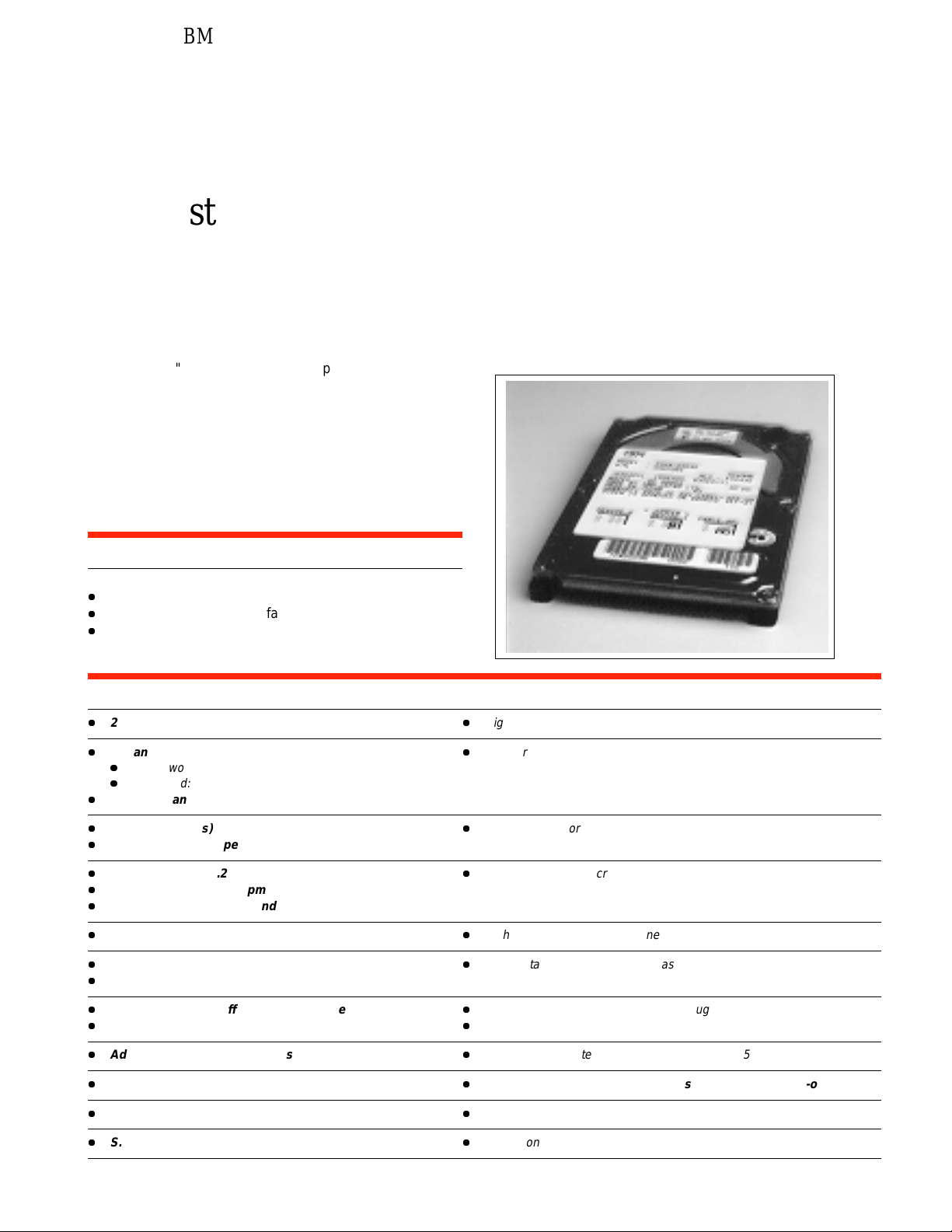
Travelstar 3GN
DYKA-22160 and DYKA-23240
The latest 2.5" disk drives from IBM provide up t o 3240MB
in a slim 9.5mm high package. Using the latest MR head
technology, IBM’s patented No-ID sector formatting, the
SMART function and advanced power saving modes and
IBM’s new ‘Load/Unload heads’ technology, IBM provides
high performance, high capacity drives, particularly suited
to the mobile computing market, and its increasing
application of multimedia.
IBM
Applications
MM
High performance portable computers
MM
Non-IT - process control/fax
MM
Removable/secure storage units.
Features Benefits
MM
2160/3240MB at (512 bytes/sector)
MM
Enhanced IDE interface with Ultra-DMA data transfer
MM
Single word:mode 2 (8.3MB/sec)
MM
Multi word:mode 2(33.3MB/sec)
MM
PIO data transfer - mode 4(16.6MB/sec)
MM
Shock 700G(1ms) non-operational
MM
Shock 150G(2ms) operational
MM
Media data rate 56.2-93.5 Mbits/s
MM
Rotational speed 4200 rpm
MM
Average seek 13 milliseconds (Read)
MM
Magneto resistive heads
MM
No-ID sector formatting
MM
PRML Data channel
MM
High capacity in slim 2.5 Inch form factor
MM
Popular interface with excellent performance
MM
Robust design for portable computing applications
MM
Excellent data rate across disk surface
MM
High areal density, low component count
MM
More data stored per track, increased sustained data transfer rate
MM
90KB segmented buffer with write cache
MM
Enhanced ECC on the fly
MM
Advanced power saving modes
MM
Load/unload heads
MM
Spin up 2.8 sec (typical)
MM
S.M.A.R.T. function
MM
Fast access to data and improved throughput
MM
High reliability
MM
Low power for battery powered applications (0.65 watt at idle state)
MM
Increased durability during power save modes and non-operation
MM
Fast recovery from standby
MM
Protection of user data
Page 2
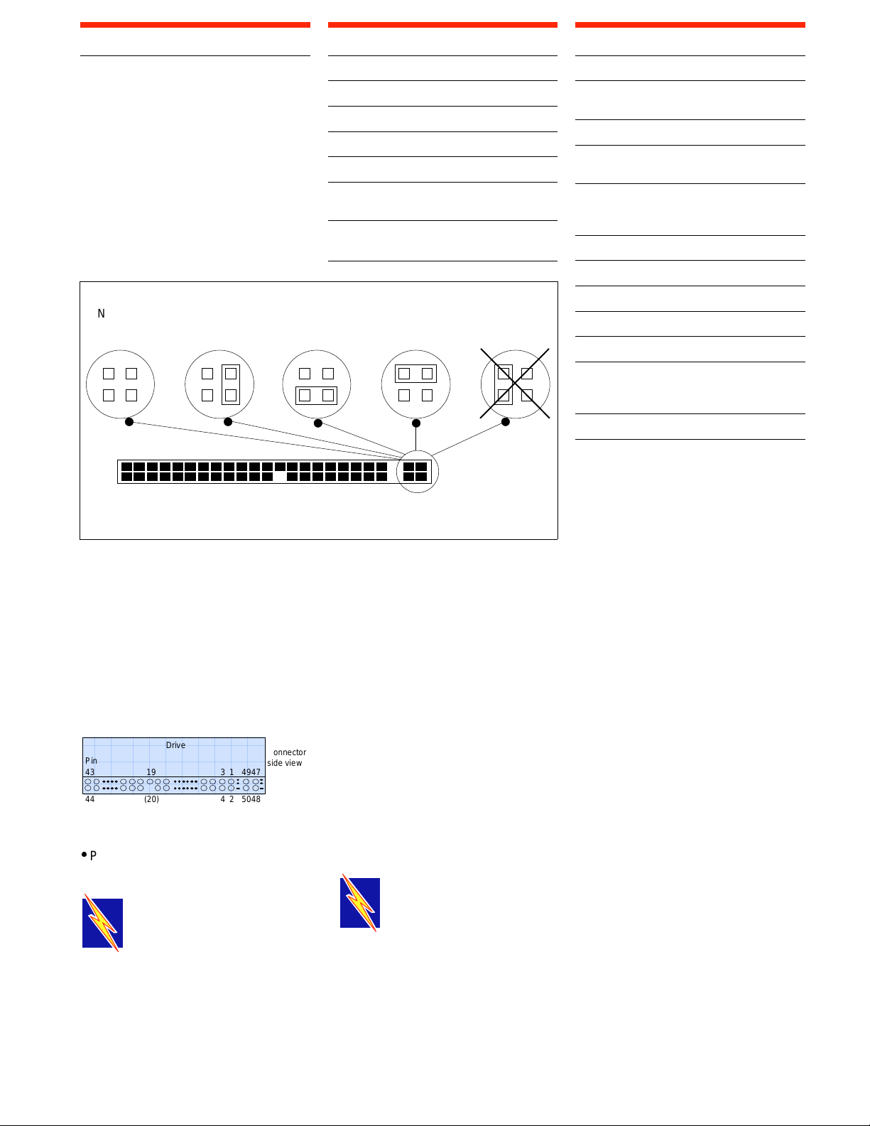
Electrical Connector Locations
AAAA
AAAA
AAAA
AAAA
AAAA
AAAA
AAAA
A
A
A
A
A
A
A
A
A
AAA
AA
AA
Data Organisation (Logical)
DC Power Requirements
Drive Address
Jumper positions are available at the
interface connector to determine the
drive address.
Using Cable Selection, the drive
address depends on the condition of pin
28 of the AT interface cable. In the case
when pin 28 is ground or low, the drive
is a Master. If pin 28 is open or high
level, the drive is a Slave.
No
Jumper
(Master)
49 47
50 48
Jumper
Position-1
(Slave)
Jumper
Position-3
(Cable Selection)
When grounded, no spin-up at POR.49-pin:
When open/pull-up, normal spin-up at POR.
Cabling
The maximum cable length from the
host system to the HDD plus circuit
pattern in the host system shall not
exceed 18 inches.
DYKA 22160 23240
Head Number 16 16
Sectors/Track 63 63
Cylinder Number 4200 6304
Sector Size 512 512
Total Customer
Usable Data Sectors 4,233,600 6,354,432
Total Customer
Usable Data Bytes
2167603200 3253469184
Jumper
Postion-4
(Reserved)
(=Master)
Never Attach
A Ju mper
Here!
Nominal Supply + 5 volts
Power Supply Ripple
(0-20Mhz)
Tolerance
1
2
100mv p-p max
± 5%
Supply Current Pop.Mean
(Nominal Condition)
Low Power Idle 3< 0.13A RMS Max (0.65W)
Active Idle <0.17A RMS Max (0.85W)
Performance Idle < 0.37A RMS Max (1.85W)
Read average
4
<0.40A RMS Max (2.0W)
Write average 4 < 0.42A RMS Max (2.1W)
Seek average
5
< 0.46A RMS Max (2.3W)
Standby < 0.06A RMS Max (0.3W)
Sleep < 0.02A RMS Max (0. 1W)
Start up (max.) 6 < 0.94A RMS Max (4.7W)
(average from
power on to ready)
6
< 0.70A RMS Max (3.5W)
Supply Rise Time 7 -100 ms
Notes:
1
The maximum supply ripple is
measured at 5V input of the HDD.
2
The disk drive shall not incur
damage for an over voltage
condition of +25% (maximum
duration of 20 ms) on the 5 volt
nominal supply.
3
The Idle current is specified at inner
track.
AT Signal Connector
The AT signal connector is designed to
mate with Dupont part number 69764044 or equivalent.
AAA
AAAA
AAAA
AAAA
AAAA
AAAA
AAAA
AAAA
AAA
AAAA
AAAA
AAA
AAAA
AAAA
AAA
AAAA
AAAA
Pin
AAA
AAAA
AAAA
AAA
AAAA
AAAA
43 19 3 1 4947
AAA
AAAA
AAAA
AAA
AAAA
AAAA
AAA
AAAA
AAAA
AAA
AAAA
AAAA
AAAA
AAAA
AAAA
AAAA
AAAA
AAAA
AAAA
AAAA
AAAA
Drive
AAAA
AAAA
AAAA
AAAA
AAAA
AAAA
AAAA
AAAA
AAAA
AAAA
AAAA
AAAA
AAAA
AAAA
AAAA
AAAA
AAAA
AAAA
AAAA
AAAA
AAAA
AAAA
AAAA
AAAA
AAAA
AAAA
AAAA
AAAA
AAAA
AAAA
AAAA
AAAA
AAAA
AAAA
AAAA
AAAA
AA
AA
AA
AA
AA
AA
AA
AA
AA
AA
485024(20)44
Connector
side view
Note:
Pin position 20 is left blank for secure
connector insertion
.
Warning: This disk drive can
be damaged Electrostatic
Discharge, please follow
recommended ESD procedures
unpacking or handling the drive. Ask
your dealer for details if you need
assistance.
4
The read/write current is specified
based on three operations of 63
sector read/write per 100 msec.
5
The seek average current is specified
based on three operations per 100
msec.
6
The worst case operating current
Includes motor surge.
PACKAGING: The drive must be protected against Electrostatic
Discharge especially when being handled. The safest way to avoid
damage is to put the drive in an anti static bag before ESD wrist straps
etc. are removed.
Drives should only be shipped in approved containers, severe damage can be
caused to the drive if the packaging does not adequately protect against the
shock levels induced when a box is dropped. Consult your IBM marketing
Page 3

Command Description
-DIOR
IORDY
-DIOW
IORDY
-DIOR
-DIOW
Conventional
Definition
The following Commands are supported
by the Drive:
Commands (Hex) P
Check Power Mode (E5) 3
Check Power Mode* (98) 3
Execute Drive Diagnostics (90) 3
Flush Cache (E7) 3
Format Track (50) 2
Format Unit (F7) 3+
Identify Device (EC) 1
Identify Device DMA (EE) 4
Idle (E3) 3
Idle* (97) 3
Idle Immediate (E1) 3
Idle Immediate* (95) 3
Initialise Drive Parameters (91) 3
Read Buffer (E4) 1
Read DMA (retry) (C8) 4
Read DMA (no retry) (C9) 4
Read Long (retry) (22) 1
Read Long (no retry) (23) 1
Read Multiple (C4) 1
Read Native Max LBA/CYL (F8) 3+
Read Sectors (retry) (20) 1
Read Sectors (no retry) (21) 1
Read Verify Sectors (retry) (40) 3
Read Verify Sectors (no retry) (41) 3
Recalibrate (1X) 3
Security Disable Password (F6) 2
Security Erase Prepare (F3) 3
Security Erase Unit (F4) 2
Security Freeze Lock (F5) 3
Security Set Password (F1) 2
Security Unlock (F2) 2
Seek (7X) 3
Set Features (EF) 3
Set Max LBA/CYL (F9) 3+
Set Multiple Mode (C6) 3
Sleep (E6) 3
Sleep* (99) 3
SMART Disable Operations (B0) 3
SMART Enable/Disable
Attribute Autosave (B0) 3
SMART Enable Operations (B0) 3
SMART Execute Off-Line
Data Collection (B0) 3
SMART Read Attribute Values (B0) 1
SMART Read Attribute Thresholds (B0) 1
SMART Return Status (B0) 3
SMART Save Attribute Values (B0) 3
Standby (E2) 3
Standby* (96) 3
Standby Immediate (EO) 3
Standby Immediate* (94) 3
Write Buffer (E8) 2
Write DMA (retry) (CA) 4
Write DMA (no retry) (CB) 4
Write Long (retry) (32) 2
Write Long (no retry) (33) 2
Write Multiple (C5) 2
Write Sectors (retry) (30) 2
Write Sectors (no retry) (31) 2
Write Verify (3C) 2
(P)rotocol:
1 PIO data IN command
2 PIO data OUT command
3 Non data command
4 DMA command
+ Vendor specific command
*Alternate command codes for previous defined
commands.
Signal Definition
The pin assignments of interface
signals are listed as follows:
PIN Signal I/O PIN Signal I/O
01 -HRESET I 02 GND
03 HDO7 I/O 04 HDO8 I/O
05 HDO6 I/O 06 HDO9 I/O
07 HDO5 I/O 08 HD10 I/O
09 HDO4 I/O 10 HD11 I/O
11 HDO3 I/O 12 HD12 I/O
13 HDO2 I/O 14 HD13 I/O
15 HDO1 I/O 16 HD14 I/O
17 HDOO I/O 18 HD15 I/O
19 GND (20) Key
21 DMARQ O 22 GND
23 -DIOW* I 24 GND
25 -DIOR* I 26 GND
27 IORDY* O 28 CSEL I
29 -DMACK I 30 GND
31 INTRQ O 32 - HIOCS16 O
33 DAO1 I 34 -PDIAG I/O
35 DAOO I 36 DAO2 I
37 -CSO I 38 -CS1 I
39 -DASP I/O 40 GND
41 +5V Logic PWR 42 +5V Motor PWR
43 GND 44 (Res)
Note:
“O” Designates an output from the
Drive.
“I” Designates an input from the
Drive.
“I/O” Designates an input/output
common.
“PWR” Designates a power supply to
the Drive.
“(Res)” Designates reserved pins which
must be left unconnected.
“*” These signal lines are redifined
during the Ultra DMA protocol to
provide special functions as
detailed in the table below:-
Special
Definition
(Ultra DMA)
Write
Operation
Read
Operation
-DDMARDY
HSTROBE
STOP
-HDMARDY
DSTROBE
STOP
Note: There are two input pins for +5
Volt power supply, “+5V LOGIC” and
“+5V MOTOR”. “+5V LOGIC” is
connected to the internal logic circuits
and “+5V MOTOR” is connected to the
spindle motor and motor driver.
Page 4

It is possible to turn on and off “+5V
AAAA
AAAA
AAAA
AAAA
AAAA
AAAA
A
A
A
A
A
A
LOGIC” by an external switch circuit to
reduce power consumption to the least
possible. In this mode, a voltage drop
out due to the motor spin up current
can be reduced by connecting “+5V
MOTOR” line into the system power
source directly.
If the above power management option
is used, all signal lines that will be
electrically active in the host system
while the HDD is disconnected from
power line shall be isolated by
Three-State line drivers. Internal
leakage through ESD protection circuit
may pull down LPUL (Least Positive Up
Level) of logic signal below
specification.
N.B. When the heads are unloaded,
they rest in a small detent. To prevent
the heads from being thrown off the
ramp during angular acceleration, a
bi-directional, normally open,
mechanical latch engages with the
actuator to stop it turning in the head
loading direction. This action causes a
‘rattle’ sound to be heard which can be
mistaken for loose parts.
Adaptive Battery Life Extension
IBM Travelstar products incorporate
software which automatically
determines the correct time to start
removing power from the drive
electronics.
respond to a new command within 40
milliseconds. The transition from
performance idle to active idle is
controlled by IBM’s patented Adaptivity
Battery Life Extender technology.
Low Power Idle
The drive is spinning but is not per
forming a command. Additionally the
drive had determined that the previous
command sequence (group of
associated commands) is complete.
Some of the drive electronics have been
powered down but it can still respond to
a new command within about 40
milliseconds. The transition from
performance idle to low power idle is
controlled by IBM's patented Adaptive
Battery Life Extender technology.
Use both lines in parallel, for regular
HDD applications.
Caution
DO NOT PRESS!
Breather Hole
MM
Do not press when you take
out the drive.
MM
Do not press when you carry
the drive.
MM
Attach the drive free from
pressing force.
MM
Do not cover Breather Hole.
Load / Unload Heads
Most software and operating systems
make use of a disk drive in bursts. The
Travelstar drives monitor the
commands which are sent from the
host to detect patterns which indicate
that a command sequence is active or
has completed. The drive can then
conserve power after each command
sequence is finished by putting the drive
into low overall power consumption and
longer battery life with no loss in
performance. If the host system
changes the number or frequency of
commands which it sends then the disk
drive will adapt automatically to this
new pattern.
Operating Models
To provide the greatest flexibility of
operation with optimum performance
and power consumption the drive has a
number of operating modes. These are
defined below.
Active Mode
The drive is performing a command,
writing cached data to disk or filling a
read ahead buffer.
Standby
The drive is not spinning and is not
performing a command. All electronics
except for the command interface is
turned off. The transition to standby is
controlled by a programmable timer
which is set by the host system using
standard ATA commands. After
receiving a new command, the drive will
start spinning again and perform the
command within 2 to 3 seconds
(typically).
Sleep
The drive is not spinning and is not
performing commands. All of the
electronics is turned off. The transition
to sleep mode is controlled by a
command which is sent by the host
system. The transition from sleep can
only be triggered by a reset.
Electromagnetic Compatibility
The drive meets the following EMC
requirements when installed in a host
system and exercised with a random
accessing routine at maximum data
rate:
One of the major advances in this
generation of products is the Load ?
Unload mechanism. When properly
used, it allows 300,000 start/stops, an
8-10x advancement.
The heads are unloaded by invoking
one of the following commands:
SOFT RESET
STANDBY
STANDBY IMMEDIATE
SLEEP
It is also invoked as one of the idle
modes. After a short period of inactivity
the adaptive Battery Life Extender
power managemen will unload the
heads to conserve energy.
Performance Idle
The drive is spinning but is not per
forming a command. It can respond
immediately if a new command is
received. The transition from active
mode to performance idle mode is
controlled by the arrival and completion
of commands from the host system.
Active Idle
The drive is spinning but is not
performing a command. Additionally
the drive had determined that the
previous command sequence (group of
associated commands) is complete.
Some of the drive electronics have
been powered down but it can still
United States Federal Communication
Commission (FCC) Rules and
Regulations Part 15, subject J Computer Devices “Class B Limits”.
European Economic Community (ECC)
directive #76/889 related to the control
of radio frequency interference and the
Verband Deutscher Elektrotechniker
(VDE) requirements of Germany
(GOP).
The product is certified for compliance
to EC directive 89/336/EEC.
Page 5

C-Tick Mark complies with Australian
100.2 ±
0.25
69.85
±
0.25
76.6
±0.
2
5
14
±0.
2
5
9.5 +0/-0.5
3±0.25
The recommended mounting screw
torque is 3.0 ± 0.5 kgf.cm.
The recommended mounting screw
depth is 3.0 ± 0.3mm for bottom and
3.5 ± 0.5mm for horizontal mounting.
AAAA
AAAA
AAAA
AAAA
AAAA
AAAA
AAAA
AAAA
AAAA
AAAA
AAAA
AAAA
AAAA
AAAA
AAAA
AAAA
AAAA
AAAA
AAAA
AAAA
AAAA
AAAA
AAAA
AAAA
AAAA
AAAA
AAAA
AAAA
AAAA
AAAA
AAAA
AAAA
AAAA
AAAA
AAAA
AAAA
AAAA
AAAA
AAAA
AAAA
AAAA
AAAA
AAAA
AAAA
AAAA
AAAA
AAAA
AAAA
AAAA
AAAA
AAAA
AAAA
AAAA
AAAA
AAAA
AAAA
AAAA
AAAA
AAAA
AAAA
AAAA
AAAA
AAAA
AAA
AAA
AAA
AAA
AAA
AAA
AAA
AAA
AAA
AAAA
AAAA
AAAA
AAAA
AAAA
AAAA
AAAA
AAAA
AAAA
AAAA
AAAA
AAAA
AAAA
AAAA
AAAA
AAAA
AAAA
AAAA
AAAA
AAAA
AAAA
AAAA
AAAA
AAAA
AAAA
AAAA
AAAA
AAAA
AAAA
AAAA
AAAA
AAAA
AAAA
AAAA
AAAA
AAAA
AAAA
AAAA
AAAA
AAAA
AAAA
AAAA
AAAA
AAAA
AAAA
AAAA
AAAA
AAAA
AAAA
AAAA
AAAA
AAAA
AAAA
AAAA
AAAA
AAAA
AAAA
AAAA
AAAA
AAAA
AAAA
AAAA
AAAA
AAAA
AAAA
AAAA
AAAA
AAAA
AAAA
AAAA
AAAA
AAAA
AAAA
AAAA
AAAA
AAAA
AAAA
AAAA
AAAA
AAAA
AAAA
AAAA
AAAA
AAAA
AAAA
AAAA
AAAA
AAAA
AAAA
AAAA
AAAA
AAAA
AAAA
AAAA
AAAA
AAAA
AAAA
AAAA
AAAA
AAAA
AAAA
AAAA
AAAA
AAAA
AAAA
AAAA
AAAA
AAAA
AAAA
AAAA
AAAA
AAAA
AAAA
AAAA
AAAA
AAAA
AAAA
AAAA
AAAA
AAAA
AAAA
AAAA
AAAA
AAAA
AAAA
AAAA
AAAA
AAAA
AAAA
AAAA
AAAA
AAAA
AAAA
AAAA
AAAA
AAAA
AAAA
AAAA
AAAA
AAAA
A
A
A
A
A
A
A
A
A
A
A
A
A
A
A
A
A
A
A
A
A
A
A
A
AAAA
AAAA
AAAA
AAAA
AAAA
AAAA
AAAA
(4x) M3
76.6 ±0.25
14 ±0.25
Rear Front
61.72 ±0.25
3.86±0.2
EMC standard, AS/NZS 3348:1995
CLASS-B.
Operating Environment
Relative Humidity:
Operating 8% to 90%
non-condensing
Non-Operating 5% to 95%
non-condensing
Wet Bulb Temperature:
Maximum Wet Bulb:
Operating 29.4°C
non-condensing
Non-Operating 40°C
non-condensing
Elevation:
Operating Altitude -300 to 3000m
Non Operating Altitude -300 to 12000m
Temperature:
Operating 5° to 55°C
Non Operating -40° to 65°C
Temperature Gradient 20°C per hour
Air Cooling Requirement
The host system must provide sufficient
air flow across the drive to maintain the
temperature at less than 60°C
(measured at the centre o f the files' top
cover).
parameters, S.M.A.R.T. devices employ
sophisticated data analysis algorithms
to predict the likelihood of near - term
degradation or fault condition. By
alerting the host system of a negative
reliability status condition, the host
system can warn the user of the
impending risk of data loss and advise
the user of appropriate action.
Since S.M.A.R.T. utilises the internal
device microprocessor and other
devices resources, there may be some
small overhead associated with its
operation. However, special care has
been taken in the design of the
S.M.A.R.T. algorithms to minimise the
impact to host system performance.
Actual impact of S.M.A.R.T. overhead
is dependent on the specific device
design and the usage patterns of the
host system. To further ensure minimal
impact to the user, S.M.A.R.T. capable
devices are shipped from the device
manufacturer's factory with the
S.M.A.R.T. feature disabled. S.M.A.R.T.
capable devices can be enabled by the
system OEMs at time of system
integration or in the field by after market
products.
Note: For further details see drive
specification.
Mechanical Data
10.14 ±0.25
Operating Shock
The drive will withstand (with no hard
error) a 150G half-sine wave shock
pulse of 2ms duration or 10G for 11ms.
Non-Operating Shock
The drive will withstand (with no
permanent damage or degradation in
performance) a 120G half-sine wave
shock pulse of 11ms duration or 700G
for 1ms.
Operating and non Operating
Vibration
Due to the complexity of this subject we
recommend that users contact the
Distributor to discuss how to perform
the necessary measurements if they
believe this to be an area which
requires evaluation.
S.M.A.R.T. Function
The intent of self - monitoring, analysis
and reporting technology (S.M.A.R.T.)
is to protect user data and prevent
unscheduled system downtime that
may be caused by predictable
degradation and/ or fault of the device.
By monitoring and storing critical
performance and calibration
Dimensions DYKA-22160/23240
Height (mm) 12.7
Width (mm) 69.85
Length (mm) 100.2
Weight (grams) 99 Typical
Mounting Orientation
5
2
±0.
3.99
Page 6

IBM OEM Europe
PO Box 41
North Harbour
Portsmouth
Hampshire
PO6 3AU
United Kingdom
Telephone: (44) 1705 561000
IBM Corporation
Storage Systems Division
5600 Cottle Road
San Jose, CA 95193
(408) 256-8000
Japan Headquarters: (81) 466-45-1384
Asia-Pacific Headquarters: (65) 320-1503
Internet access at:
http://www.ibm.com/storage/hddtech
Registered in England: No. 741598
Registered Office: PO Box 41, North Harbour,
Portsmouth. Hampshire P06 3AU.
UK company-wide registration to ISO90001.
Certificate number FM12587.
IBM is the registered trademark of International
Business Machines Corporation.
AMP is a trademark of AMP Incorporated
Molex is a trademark of Molex Incorporated
DATA MATE is a trademark of AMP Incorporated
Other company, product and service names may be
trademarks or service marks of others.
Produced by European SIT Lab.
© International Business Machines Corporation 1997.
This data sheet is not a substitute for the full
production specification, which should be used when
detailed information is required.
Product Description data represents IBM’s design
objectives and is provided for comparative purposes;
actual results may vary based on a variety of factors.
This product data does not constitute a warranty.
Questions regarding IBM’s warranty terms or
methodology used to derive this data should be
referred to your IBM OEM representative. Data
subject to change without notice.
Date:27th November 1997
Distributor:
IBM
 Loading...