

Page 1

Front cover
The IBM TotalStorage Storage
DS8000 Series:s:
Concepts and ArchitectureArchitecture
Advanced features and performance
breakthrough with POWER5 technology
Configuration flexibility with LPAR
and virtualization
Highly scalable solutions for
on demand storage
Cathy Warrick
Olivier Alluis
Werner Bauer
Heinz Blaschek
Andre Fourie
Juan Antonio Garay
Torsten Knobloch
Donald C Laing
Christine O’Sullivan
Stu S Preacher
Torsten Rothenwaldt
Tetsuroh Sano
Jing Nan Tang
Anthony Vandewerdt
Alexander Warmuth
Roland Wolf
ibm.com/redbooks
Page 2

Page 3

International Technical Support Organization
The IBM TotalStorage DS8000 Series:
Concepts and Architecture
April 2005
SG24-6452-00
Page 4

Note: Before using this information and the product it supports, read the information in “Notices” on
page xiii.
First Edition (April 2005)
This edition applies to the DS8000 series per the October 12, 2004 announcement. Please note that
pre-release code was used for the screen captures and command output; some details may vary from the
generally available product.
Note: This book is based on a pre-GA version of a product and may not apply when the product becomes
generally available. We recommend that you consult the product documentation or follow-on versions of
this redbook for more current information.
© Copyright International Business Machines Corporation 2005. All rights reserved.
Note to U.S. Government Users Restricted Rights -- Use, duplication or disclosure restricted by GSA ADP Schedule
Contract with IBM Corp.
Page 5

Contents
Notices . . . . . . . . . . . . . . . . . . . . . . . . . . . . . . . . . . . . . . . . . . . . . . . . . . . . . . . . . . . . . . . . xiii
Trademarks . . . . . . . . . . . . . . . . . . . . . . . . . . . . . . . . . . . . . . . . . . . . . . . . . . . . . . . . . . . . . xiv
Preface . . . . . . . . . . . . . . . . . . . . . . . . . . . . . . . . . . . . . . . . . . . . . . . . . . . . . . . . . . . . . . . . . xv
The team that wrote this redbook. . . . . . . . . . . . . . . . . . . . . . . . . . . . . . . . . . . . . . . . . . . . . .xv
Become a published author . . . . . . . . . . . . . . . . . . . . . . . . . . . . . . . . . . . . . . . . . . . . . . . . . xix
Comments welcome. . . . . . . . . . . . . . . . . . . . . . . . . . . . . . . . . . . . . . . . . . . . . . . . . . . . . . . xix
Part 1. Introduction. . . . . . . . . . . . . . . . . . . . . . . . . . . . . . . . . . . . . . . . . . . . . . . . . . . . . . . . . . . . . . . . . . . . 1
Chapter 1. Introduction to the DS8000 series. . . . . . . . . . . . . . . . . . . . . . . . . . . . . . . . . . 3
1.1 The DS8000, a member of the TotalStorage DS family . . . . . . . . . . . . . . . . . . . . . . . . . 4
1.1.1 Infrastructure Simplification. . . . . . . . . . . . . . . . . . . . . . . . . . . . . . . . . . . . . . . . . . . 4
1.1.2 Business Continuity . . . . . . . . . . . . . . . . . . . . . . . . . . . . . . . . . . . . . . . . . . . . . . . . 4
1.1.3 Information Lifecycle Management . . . . . . . . . . . . . . . . . . . . . . . . . . . . . . . . . . . . . 4
1.2 Overview of the DS8000 series. . . . . . . . . . . . . . . . . . . . . . . . . . . . . . . . . . . . . . . . . . . . 4
1.2.1 Hardware overview . . . . . . . . . . . . . . . . . . . . . . . . . . . . . . . . . . . . . . . . . . . . . . . . . 6
1.2.2 Storage capacity . . . . . . . . . . . . . . . . . . . . . . . . . . . . . . . . . . . . . . . . . . . . . . . . . . . 7
1.2.3 Storage system logical partitions (LPARs) . . . . . . . . . . . . . . . . . . . . . . . . . . . . . . . 7
1.2.4 Supported environments. . . . . . . . . . . . . . . . . . . . . . . . . . . . . . . . . . . . . . . . . . . . . 8
1.2.5 Resiliency Family for Business Continuity . . . . . . . . . . . . . . . . . . . . . . . . . . . . . . . 8
1.2.6 Interoperability . . . . . . . . . . . . . . . . . . . . . . . . . . . . . . . . . . . . . . . . . . . . . . . . . . . 10
1.2.7 Service and setup . . . . . . . . . . . . . . . . . . . . . . . . . . . . . . . . . . . . . . . . . . . . . . . . . 10
1.3 Positioning. . . . . . . . . . . . . . . . . . . . . . . . . . . . . . . . . . . . . . . . . . . . . . . . . . . . . . . . . . . 11
1.3.1 Common set of functions . . . . . . . . . . . . . . . . . . . . . . . . . . . . . . . . . . . . . . . . . . . 11
1.3.2 Common management functions . . . . . . . . . . . . . . . . . . . . . . . . . . . . . . . . . . . . . 12
1.3.3 Scalability and configuration flexibility. . . . . . . . . . . . . . . . . . . . . . . . . . . . . . . . . . 13
1.3.4 Future directions of storage system LPARs . . . . . . . . . . . . . . . . . . . . . . . . . . . . . 13
1.4 Performance . . . . . . . . . . . . . . . . . . . . . . . . . . . . . . . . . . . . . . . . . . . . . . . . . . . . . . . . . 14
1.4.1 Sequential Prefetching in Adaptive Replacement Cache (SARC) . . . . . . . . . . . . 14
1.4.2 IBM TotalStorage Multipath Subsystem Device Driver (SDD) . . . . . . . . . . . . . . . 14
1.4.3 Performance for zSeries . . . . . . . . . . . . . . . . . . . . . . . . . . . . . . . . . . . . . . . . . . . . 14
1.5 Summary. . . . . . . . . . . . . . . . . . . . . . . . . . . . . . . . . . . . . . . . . . . . . . . . . . . . . . . . . . . . 15
Part 2. Architecture. . . . . . . . . . . . . . . . . . . . . . . . . . . . . . . . . . . . . . . . . . . . . . . . . . . . . . . . . . . . . . . . . . . 17
Chapter 2. Components . . . . . . . . . . . . . . . . . . . . . . . . . . . . . . . . . . . . . . . . . . . . . . . . . . 19
2.1 Frames . . . . . . . . . . . . . . . . . . . . . . . . . . . . . . . . . . . . . . . . . . . . . . . . . . . . . . . . . . . . . 20
2.1.1 Base frame . . . . . . . . . . . . . . . . . . . . . . . . . . . . . . . . . . . . . . . . . . . . . . . . . . . . . . 20
2.1.2 Expansion frame . . . . . . . . . . . . . . . . . . . . . . . . . . . . . . . . . . . . . . . . . . . . . . . . . . 21
2.1.3 Rack operator panel . . . . . . . . . . . . . . . . . . . . . . . . . . . . . . . . . . . . . . . . . . . . . . . 21
2.2 Architecture . . . . . . . . . . . . . . . . . . . . . . . . . . . . . . . . . . . . . . . . . . . . . . . . . . . . . . . . . . 22
2.2.1 Server-based SMP design . . . . . . . . . . . . . . . . . . . . . . . . . . . . . . . . . . . . . . . . . . 24
2.2.2 Cache management . . . . . . . . . . . . . . . . . . . . . . . . . . . . . . . . . . . . . . . . . . . . . . . 24
2.3 Processor complex . . . . . . . . . . . . . . . . . . . . . . . . . . . . . . . . . . . . . . . . . . . . . . . . . . . . 26
2.3.1 RIO-G . . . . . . . . . . . . . . . . . . . . . . . . . . . . . . . . . . . . . . . . . . . . . . . . . . . . . . . . . . 29
2.3.2 I/O enclosures . . . . . . . . . . . . . . . . . . . . . . . . . . . . . . . . . . . . . . . . . . . . . . . . . . . . 29
2.4 Disk subsystem . . . . . . . . . . . . . . . . . . . . . . . . . . . . . . . . . . . . . . . . . . . . . . . . . . . . . . . 30
2.4.1 Device adapters . . . . . . . . . . . . . . . . . . . . . . . . . . . . . . . . . . . . . . . . . . . . . . . . . . 30
© Copyright IBM Corp. 2005. All rights reserved. iii
Page 6

2.4.2 Disk enclosures. . . . . . . . . . . . . . . . . . . . . . . . . . . . . . . . . . . . . . . . . . . . . . . . . . . 31
2.5 Host adapters . . . . . . . . . . . . . . . . . . . . . . . . . . . . . . . . . . . . . . . . . . . . . . . . . . . . . . . . 37
2.5.1 FICON and Fibre Channel protocol host adapters . . . . . . . . . . . . . . . . . . . . . . . . 38
2.6 Power and cooling. . . . . . . . . . . . . . . . . . . . . . . . . . . . . . . . . . . . . . . . . . . . . . . . . . . . . 39
2.7 Management console network . . . . . . . . . . . . . . . . . . . . . . . . . . . . . . . . . . . . . . . . . . . 40
2.8 Summary. . . . . . . . . . . . . . . . . . . . . . . . . . . . . . . . . . . . . . . . . . . . . . . . . . . . . . . . . . . . 41
Chapter 3. Storage system LPARs (Logical partitions). . . . . . . . . . . . . . . . . . . . . . . . . 43
3.1 Introduction to logical partitioning . . . . . . . . . . . . . . . . . . . . . . . . . . . . . . . . . . . . . . . . . 44
3.1.1 Virtualization Engine technology . . . . . . . . . . . . . . . . . . . . . . . . . . . . . . . . . . . . . . 44
3.1.2 Partitioning concepts. . . . . . . . . . . . . . . . . . . . . . . . . . . . . . . . . . . . . . . . . . . . . . . 44
3.1.3 Why Logically Partition? . . . . . . . . . . . . . . . . . . . . . . . . . . . . . . . . . . . . . . . . . . . . 47
3.2 DS8000 and LPAR . . . . . . . . . . . . . . . . . . . . . . . . . . . . . . . . . . . . . . . . . . . . . . . . . . . . 48
3.2.1 LPAR and storage facility images . . . . . . . . . . . . . . . . . . . . . . . . . . . . . . . . . . . . . 48
3.2.2 DS8300 LPAR implementation . . . . . . . . . . . . . . . . . . . . . . . . . . . . . . . . . . . . . . . 49
3.2.3 Storage facility image hardware components . . . . . . . . . . . . . . . . . . . . . . . . . . . . 50
3.2.4 DS8300 Model 9A2 configuration options. . . . . . . . . . . . . . . . . . . . . . . . . . . . . . . 52
3.3 LPAR security through POWER™ Hypervisor (PHYP). . . . . . . . . . . . . . . . . . . . . . . . . 54
3.4 LPAR and Copy Services . . . . . . . . . . . . . . . . . . . . . . . . . . . . . . . . . . . . . . . . . . . . . . . 55
3.5 LPAR benefits . . . . . . . . . . . . . . . . . . . . . . . . . . . . . . . . . . . . . . . . . . . . . . . . . . . . . . . . 56
3.6 Summary. . . . . . . . . . . . . . . . . . . . . . . . . . . . . . . . . . . . . . . . . . . . . . . . . . . . . . . . . . . . 59
Chapter 4. RAS . . . . . . . . . . . . . . . . . . . . . . . . . . . . . . . . . . . . . . . . . . . . . . . . . . . . . . . . . 61
4.1 Naming . . . . . . . . . . . . . . . . . . . . . . . . . . . . . . . . . . . . . . . . . . . . . . . . . . . . . . . . . . . . . 62
4.2 Processor complex RAS . . . . . . . . . . . . . . . . . . . . . . . . . . . . . . . . . . . . . . . . . . . . . . . . 63
4.3 Hypervisor: Storage image independence . . . . . . . . . . . . . . . . . . . . . . . . . . . . . . . . . . 66
4.3.1 RIO-G - a self-healing interconnect. . . . . . . . . . . . . . . . . . . . . . . . . . . . . . . . . . . . 67
4.3.2 I/O enclosure. . . . . . . . . . . . . . . . . . . . . . . . . . . . . . . . . . . . . . . . . . . . . . . . . . . . . 67
4.4 Server RAS . . . . . . . . . . . . . . . . . . . . . . . . . . . . . . . . . . . . . . . . . . . . . . . . . . . . . . . . . . 67
4.4.1 Metadata checks . . . . . . . . . . . . . . . . . . . . . . . . . . . . . . . . . . . . . . . . . . . . . . . . . . 67
4.4.2 Server failover and failback. . . . . . . . . . . . . . . . . . . . . . . . . . . . . . . . . . . . . . . . . . 68
4.4.3 NVS recovery after complete power loss . . . . . . . . . . . . . . . . . . . . . . . . . . . . . . . 70
4.5 Host connection availability. . . . . . . . . . . . . . . . . . . . . . . . . . . . . . . . . . . . . . . . . . . . . . 71
4.5.1 Open systems host connection. . . . . . . . . . . . . . . . . . . . . . . . . . . . . . . . . . . . . . . 74
4.5.2 zSeries host connection . . . . . . . . . . . . . . . . . . . . . . . . . . . . . . . . . . . . . . . . . . . . 74
4.6 Disk subsystem . . . . . . . . . . . . . . . . . . . . . . . . . . . . . . . . . . . . . . . . . . . . . . . . . . . . . . . 75
4.6.1 Disk path redundancy . . . . . . . . . . . . . . . . . . . . . . . . . . . . . . . . . . . . . . . . . . . . . . 75
4.6.2 RAID-5 overview . . . . . . . . . . . . . . . . . . . . . . . . . . . . . . . . . . . . . . . . . . . . . . . . . . 76
4.6.3 RAID-10 overview . . . . . . . . . . . . . . . . . . . . . . . . . . . . . . . . . . . . . . . . . . . . . . . . . 76
4.6.4 Spare creation. . . . . . . . . . . . . . . . . . . . . . . . . . . . . . . . . . . . . . . . . . . . . . . . . . . . 77
4.6.5 Predictive Failure Analysis® (PFA) . . . . . . . . . . . . . . . . . . . . . . . . . . . . . . . . . . . . 78
4.6.6 Disk scrubbing . . . . . . . . . . . . . . . . . . . . . . . . . . . . . . . . . . . . . . . . . . . . . . . . . . . 79
4.7 Power and cooling. . . . . . . . . . . . . . . . . . . . . . . . . . . . . . . . . . . . . . . . . . . . . . . . . . . . . 79
4.7.1 Building power loss . . . . . . . . . . . . . . . . . . . . . . . . . . . . . . . . . . . . . . . . . . . . . . . . 80
4.7.2 Power fluctuation protection . . . . . . . . . . . . . . . . . . . . . . . . . . . . . . . . . . . . . . . . . 80
4.7.3 Power control of the DS8000 . . . . . . . . . . . . . . . . . . . . . . . . . . . . . . . . . . . . . . . . 80
4.7.4 Emergency power off (EPO) . . . . . . . . . . . . . . . . . . . . . . . . . . . . . . . . . . . . . . . . . 80
4.8 Microcode updates . . . . . . . . . . . . . . . . . . . . . . . . . . . . . . . . . . . . . . . . . . . . . . . . . . . . 81
4.9 Management console . . . . . . . . . . . . . . . . . . . . . . . . . . . . . . . . . . . . . . . . . . . . . . . . . . 82
4.10 Summary. . . . . . . . . . . . . . . . . . . . . . . . . . . . . . . . . . . . . . . . . . . . . . . . . . . . . . . . . . . 82
Chapter 5. Virtualization concepts . . . . . . . . . . . . . . . . . . . . . . . . . . . . . . . . . . . . . . . . . 83
5.1 Virtualization definition . . . . . . . . . . . . . . . . . . . . . . . . . . . . . . . . . . . . . . . . . . . . . . . . . 84
5.2 Storage system virtualization . . . . . . . . . . . . . . . . . . . . . . . . . . . . . . . . . . . . . . . . . . . . 84
iv DS8000 Series: Concepts and Architecture
Page 7

5.3 The abstraction layers for disk virtualization . . . . . . . . . . . . . . . . . . . . . . . . . . . . . . . . . 85
5.3.1 Array sites . . . . . . . . . . . . . . . . . . . . . . . . . . . . . . . . . . . . . . . . . . . . . . . . . . . . . . . 86
5.3.2 Arrays . . . . . . . . . . . . . . . . . . . . . . . . . . . . . . . . . . . . . . . . . . . . . . . . . . . . . . . . . . 87
5.3.3 Ranks . . . . . . . . . . . . . . . . . . . . . . . . . . . . . . . . . . . . . . . . . . . . . . . . . . . . . . . . . . 88
5.3.4 Extent pools . . . . . . . . . . . . . . . . . . . . . . . . . . . . . . . . . . . . . . . . . . . . . . . . . . . . . 89
5.3.5 Logical volumes . . . . . . . . . . . . . . . . . . . . . . . . . . . . . . . . . . . . . . . . . . . . . . . . . . 91
5.3.6 Logical subsystems (LSS). . . . . . . . . . . . . . . . . . . . . . . . . . . . . . . . . . . . . . . . . . . 94
5.3.7 Volume access . . . . . . . . . . . . . . . . . . . . . . . . . . . . . . . . . . . . . . . . . . . . . . . . . . . 96
5.3.8 Summary of the virtualization hierarchy . . . . . . . . . . . . . . . . . . . . . . . . . . . . . . . . 98
5.3.9 Placement of data . . . . . . . . . . . . . . . . . . . . . . . . . . . . . . . . . . . . . . . . . . . . . . . . . 99
5.4 Benefits of virtualization . . . . . . . . . . . . . . . . . . . . . . . . . . . . . . . . . . . . . . . . . . . . . . . 100
Chapter 6. IBM TotalStorage DS8000 model overview and scalability. . . . . . . . . . . . 103
6.1 DS8000 highlights . . . . . . . . . . . . . . . . . . . . . . . . . . . . . . . . . . . . . . . . . . . . . . . . . . . . 104
6.1.1 Model naming conventions . . . . . . . . . . . . . . . . . . . . . . . . . . . . . . . . . . . . . . . . . 104
6.1.2 DS8100 Model 921 . . . . . . . . . . . . . . . . . . . . . . . . . . . . . . . . . . . . . . . . . . . . . . . 105
6.1.3 DS8300 Models 922 and 9A2 . . . . . . . . . . . . . . . . . . . . . . . . . . . . . . . . . . . . . . . 106
6.2 Model comparison . . . . . . . . . . . . . . . . . . . . . . . . . . . . . . . . . . . . . . . . . . . . . . . . . . . . 108
6.3 Designed for scalability . . . . . . . . . . . . . . . . . . . . . . . . . . . . . . . . . . . . . . . . . . . . . . . . 109
6.3.1 Scalability for capacity . . . . . . . . . . . . . . . . . . . . . . . . . . . . . . . . . . . . . . . . . . . . 109
6.3.2 Scalability for performance . . . . . . . . . . . . . . . . . . . . . . . . . . . . . . . . . . . . . . . . . 110
6.3.3 Model upgrades . . . . . . . . . . . . . . . . . . . . . . . . . . . . . . . . . . . . . . . . . . . . . . . . . 113
Chapter 7. Copy Services. . . . . . . . . . . . . . . . . . . . . . . . . . . . . . . . . . . . . . . . . . . . . . . . 115
7.1 Introduction to Copy Services . . . . . . . . . . . . . . . . . . . . . . . . . . . . . . . . . . . . . . . . . . . 116
7.2 Copy Services functions . . . . . . . . . . . . . . . . . . . . . . . . . . . . . . . . . . . . . . . . . . . . . . . 116
7.2.1 Point-in-Time Copy (FlashCopy). . . . . . . . . . . . . . . . . . . . . . . . . . . . . . . . . . . . . 116
7.2.2 FlashCopy options . . . . . . . . . . . . . . . . . . . . . . . . . . . . . . . . . . . . . . . . . . . . . . . 118
7.2.3 Remote Mirror and Copy (Peer-to-Peer Remote Copy) . . . . . . . . . . . . . . . . . . . 123
7.2.4 Comparison of the Remote Mirror and Copy functions. . . . . . . . . . . . . . . . . . . . 130
7.2.5 What is a Consistency Group? . . . . . . . . . . . . . . . . . . . . . . . . . . . . . . . . . . . . . . 132
7.3 Interfaces for Copy Services . . . . . . . . . . . . . . . . . . . . . . . . . . . . . . . . . . . . . . . . . . . . 136
7.3.1 Storage Hardware Management Console (S-HMC) . . . . . . . . . . . . . . . . . . . . . . 136
7.3.2 DS Storage Manager Web-based interface . . . . . . . . . . . . . . . . . . . . . . . . . . . . 137
7.3.3 DS Command-Line Interface (DS CLI) . . . . . . . . . . . . . . . . . . . . . . . . . . . . . . . . 138
7.3.4 DS Open application programming Interface (API). . . . . . . . . . . . . . . . . . . . . . . 138
7.4 Interoperability with ESS . . . . . . . . . . . . . . . . . . . . . . . . . . . . . . . . . . . . . . . . . . . . . . . 139
7.5 Future Plans . . . . . . . . . . . . . . . . . . . . . . . . . . . . . . . . . . . . . . . . . . . . . . . . . . . . . . . . 139
Part 3. Planning and configuration . . . . . . . . . . . . . . . . . . . . . . . . . . . . . . . . . . . . . . . . . . . . . . . . . . . . . 141
Chapter 8. Installation planning. . . . . . . . . . . . . . . . . . . . . . . . . . . . . . . . . . . . . . . . . . . 143
8.1 General considerations . . . . . . . . . . . . . . . . . . . . . . . . . . . . . . . . . . . . . . . . . . . . . . . . 144
8.2 Delivery requirements . . . . . . . . . . . . . . . . . . . . . . . . . . . . . . . . . . . . . . . . . . . . . . . . . 144
8.3 Installation site preparation . . . . . . . . . . . . . . . . . . . . . . . . . . . . . . . . . . . . . . . . . . . . . 145
8.3.1 Floor and space requirements . . . . . . . . . . . . . . . . . . . . . . . . . . . . . . . . . . . . . . 145
8.3.2 Power requirements . . . . . . . . . . . . . . . . . . . . . . . . . . . . . . . . . . . . . . . . . . . . . . 147
8.3.3 Environmental requirements . . . . . . . . . . . . . . . . . . . . . . . . . . . . . . . . . . . . . . . . 149
8.4 Host attachment . . . . . . . . . . . . . . . . . . . . . . . . . . . . . . . . . . . . . . . . . . . . . . . . . . . . . 150
8.4.1 Attaching to open systems hosts . . . . . . . . . . . . . . . . . . . . . . . . . . . . . . . . . . . . 150
8.4.2 ESCON-attached S/390 and zSeries hosts . . . . . . . . . . . . . . . . . . . . . . . . . . . . 151
8.4.3 FICON-attached S/390 and zSeries hosts . . . . . . . . . . . . . . . . . . . . . . . . . . . . . 151
8.4.4 Where to get the updated information for host attachment . . . . . . . . . . . . . . . . . 152
8.5 Network and SAN requirements . . . . . . . . . . . . . . . . . . . . . . . . . . . . . . . . . . . . . . . . . 153
Contents v
Page 8

8.5.1 S-HMC network requirements. . . . . . . . . . . . . . . . . . . . . . . . . . . . . . . . . . . . . . . 153
8.5.2 Remote support connection requirements . . . . . . . . . . . . . . . . . . . . . . . . . . . . . 154
8.5.3 Remote power control requirements . . . . . . . . . . . . . . . . . . . . . . . . . . . . . . . . . . 154
8.5.4 SAN requirements. . . . . . . . . . . . . . . . . . . . . . . . . . . . . . . . . . . . . . . . . . . . . . . . 154
Chapter 9. Configuration planning . . . . . . . . . . . . . . . . . . . . . . . . . . . . . . . . . . . . . . . . 157
9.1 Configuration planning overview . . . . . . . . . . . . . . . . . . . . . . . . . . . . . . . . . . . . . . . . . 158
9.2 Storage Hardware Management Console (S-HMC) . . . . . . . . . . . . . . . . . . . . . . . . . . 158
9.2.1 External S-HMC . . . . . . . . . . . . . . . . . . . . . . . . . . . . . . . . . . . . . . . . . . . . . . . . . 159
9.2.2 S-HMC software components . . . . . . . . . . . . . . . . . . . . . . . . . . . . . . . . . . . . . . . 160
9.2.3 S-HMC network topology . . . . . . . . . . . . . . . . . . . . . . . . . . . . . . . . . . . . . . . . . . 162
9.2.4 FTP Offload option . . . . . . . . . . . . . . . . . . . . . . . . . . . . . . . . . . . . . . . . . . . . . . . 166
9.3 DS8000 licensed functions . . . . . . . . . . . . . . . . . . . . . . . . . . . . . . . . . . . . . . . . . . . . . 167
9.3.1 Operating environment license (OEL) - required feature . . . . . . . . . . . . . . . . . . 167
9.3.2 Point-in-Time Copy function (2244 Model PTC) . . . . . . . . . . . . . . . . . . . . . . . . . 168
9.3.3 Remote Mirror and Copy functions (2244 Model RMC) . . . . . . . . . . . . . . . . . . . 169
9.3.4 Remote Mirror for z/OS (2244 Model RMZ) . . . . . . . . . . . . . . . . . . . . . . . . . . . . 169
9.3.5 Parallel Access Volumes (2244 Model PAV) . . . . . . . . . . . . . . . . . . . . . . . . . . . 170
9.3.6 Ordering licensed functions . . . . . . . . . . . . . . . . . . . . . . . . . . . . . . . . . . . . . . . . 170
9.3.7 Disk storage feature activation . . . . . . . . . . . . . . . . . . . . . . . . . . . . . . . . . . . . . . 173
9.3.8 Scenarios for managing licensing . . . . . . . . . . . . . . . . . . . . . . . . . . . . . . . . . . . . 174
9.4 Capacity planning . . . . . . . . . . . . . . . . . . . . . . . . . . . . . . . . . . . . . . . . . . . . . . . . . . . . 174
9.4.1 Logical configurations . . . . . . . . . . . . . . . . . . . . . . . . . . . . . . . . . . . . . . . . . . . . . 174
9.4.2 Sparing rules . . . . . . . . . . . . . . . . . . . . . . . . . . . . . . . . . . . . . . . . . . . . . . . . . . . . 176
9.4.3 Sparing examples . . . . . . . . . . . . . . . . . . . . . . . . . . . . . . . . . . . . . . . . . . . . . . . . 177
9.4.4 IBM Standby Capacity on Demand (Standby CoD) . . . . . . . . . . . . . . . . . . . . . . 180
9.4.5 Capacity and well-balanced configuration. . . . . . . . . . . . . . . . . . . . . . . . . . . . . . 181
9.5 Data migration planning . . . . . . . . . . . . . . . . . . . . . . . . . . . . . . . . . . . . . . . . . . . . . . . 183
9.5.1 Operating system mirroring. . . . . . . . . . . . . . . . . . . . . . . . . . . . . . . . . . . . . . . . . 184
9.5.2 Basic commands. . . . . . . . . . . . . . . . . . . . . . . . . . . . . . . . . . . . . . . . . . . . . . . . . 184
9.5.3 Software packages . . . . . . . . . . . . . . . . . . . . . . . . . . . . . . . . . . . . . . . . . . . . . . . 184
9.5.4 Remote copy technologies . . . . . . . . . . . . . . . . . . . . . . . . . . . . . . . . . . . . . . . . . 184
9.5.5 Migration services and appliances . . . . . . . . . . . . . . . . . . . . . . . . . . . . . . . . . . . 185
9.5.6 z/OS data migration methods . . . . . . . . . . . . . . . . . . . . . . . . . . . . . . . . . . . . . . . 185
9.6 Planning for performance . . . . . . . . . . . . . . . . . . . . . . . . . . . . . . . . . . . . . . . . . . . . . . 186
9.6.1 Disk Magic . . . . . . . . . . . . . . . . . . . . . . . . . . . . . . . . . . . . . . . . . . . . . . . . . . . . . 187
9.6.2 Size of cache storage . . . . . . . . . . . . . . . . . . . . . . . . . . . . . . . . . . . . . . . . . . . . . 187
9.6.3 Number of host ports/channels . . . . . . . . . . . . . . . . . . . . . . . . . . . . . . . . . . . . . . 187
9.6.4 Remote copy . . . . . . . . . . . . . . . . . . . . . . . . . . . . . . . . . . . . . . . . . . . . . . . . . . . . 187
9.6.5 Parallel Access Volumes (z/OS only) . . . . . . . . . . . . . . . . . . . . . . . . . . . . . . . . . 187
9.6.6 I/O priority queuing (z/OS only). . . . . . . . . . . . . . . . . . . . . . . . . . . . . . . . . . . . . . 187
9.6.7 Monitoring performance . . . . . . . . . . . . . . . . . . . . . . . . . . . . . . . . . . . . . . . . . . . 187
9.6.8 Hot spot avoidance . . . . . . . . . . . . . . . . . . . . . . . . . . . . . . . . . . . . . . . . . . . . . . . 188
Chapter 10. The DS Storage Manager - logical configuration. . . . . . . . . . . . . . . . . . . 189
10.1 Configuration hierarchy, terminology, and concepts . . . . . . . . . . . . . . . . . . . . . . . . . 190
10.1.1 Storage configuration terminology . . . . . . . . . . . . . . . . . . . . . . . . . . . . . . . . . . 190
10.1.2 Summary of the DS Storage Manager logical configuration steps . . . . . . . . . . 199
10.2 Introducing the GUI and logical configuration panels . . . . . . . . . . . . . . . . . . . . . . . . 202
10.2.1 Connecting to the DS8000 . . . . . . . . . . . . . . . . . . . . . . . . . . . . . . . . . . . . . . . . 202
10.2.2 The Welcome panel . . . . . . . . . . . . . . . . . . . . . . . . . . . . . . . . . . . . . . . . . . . . . 203
10.2.3 Navigating the GUI . . . . . . . . . . . . . . . . . . . . . . . . . . . . . . . . . . . . . . . . . . . . . . 208
10.3 The logical configuration process . . . . . . . . . . . . . . . . . . . . . . . . . . . . . . . . . . . . . . . 211
vi DS8000 Series: Concepts and Architecture
Page 9

10.3.1 Configuring a storage complex . . . . . . . . . . . . . . . . . . . . . . . . . . . . . . . . . . . . . 211
10.3.2 Configuring the storage unit . . . . . . . . . . . . . . . . . . . . . . . . . . . . . . . . . . . . . . . 212
10.3.3 Configuring the logical host systems. . . . . . . . . . . . . . . . . . . . . . . . . . . . . . . . . 216
10.3.4 Creating arrays from array sites . . . . . . . . . . . . . . . . . . . . . . . . . . . . . . . . . . . . 219
10.3.5 Creating extent pools . . . . . . . . . . . . . . . . . . . . . . . . . . . . . . . . . . . . . . . . . . . . 221
10.3.6 Creating FB volumes from extents . . . . . . . . . . . . . . . . . . . . . . . . . . . . . . . . . . 222
10.3.7 Creating volume groups . . . . . . . . . . . . . . . . . . . . . . . . . . . . . . . . . . . . . . . . . . 224
10.3.8 Assigning LUNs to the hosts. . . . . . . . . . . . . . . . . . . . . . . . . . . . . . . . . . . . . . . 226
10.3.9 Deleting LUNs and recovering space in the extent pool . . . . . . . . . . . . . . . . . . 226
10.3.10 Creating CKD LCUs . . . . . . . . . . . . . . . . . . . . . . . . . . . . . . . . . . . . . . . . . . . . 227
10.3.11 Creating CKD volumes . . . . . . . . . . . . . . . . . . . . . . . . . . . . . . . . . . . . . . . . . . 227
10.3.12 Displaying the storage unit WWNN. . . . . . . . . . . . . . . . . . . . . . . . . . . . . . . . . 228
10.4 Summary. . . . . . . . . . . . . . . . . . . . . . . . . . . . . . . . . . . . . . . . . . . . . . . . . . . . . . . . . . 229
Chapter 11. DS CLI . . . . . . . . . . . . . . . . . . . . . . . . . . . . . . . . . . . . . . . . . . . . . . . . . . . . . 231
11.1 Introduction . . . . . . . . . . . . . . . . . . . . . . . . . . . . . . . . . . . . . . . . . . . . . . . . . . . . . . . . 232
11.2 Functionality . . . . . . . . . . . . . . . . . . . . . . . . . . . . . . . . . . . . . . . . . . . . . . . . . . . . . . . 232
11.3 Supported environments . . . . . . . . . . . . . . . . . . . . . . . . . . . . . . . . . . . . . . . . . . . . . . 233
11.4 Installation methods . . . . . . . . . . . . . . . . . . . . . . . . . . . . . . . . . . . . . . . . . . . . . . . . . 233
11.5 Command flow . . . . . . . . . . . . . . . . . . . . . . . . . . . . . . . . . . . . . . . . . . . . . . . . . . . . . 234
11.6 User security . . . . . . . . . . . . . . . . . . . . . . . . . . . . . . . . . . . . . . . . . . . . . . . . . . . . . . . 239
11.7 Usage concepts . . . . . . . . . . . . . . . . . . . . . . . . . . . . . . . . . . . . . . . . . . . . . . . . . . . . 239
11.7.1 Command modes . . . . . . . . . . . . . . . . . . . . . . . . . . . . . . . . . . . . . . . . . . . . . . . 239
11.7.2 Syntax conventions. . . . . . . . . . . . . . . . . . . . . . . . . . . . . . . . . . . . . . . . . . . . . . 241
11.7.3 User assistance . . . . . . . . . . . . . . . . . . . . . . . . . . . . . . . . . . . . . . . . . . . . . . . . 241
11.7.4 Return codes. . . . . . . . . . . . . . . . . . . . . . . . . . . . . . . . . . . . . . . . . . . . . . . . . . . 242
11.8 Usage examples . . . . . . . . . . . . . . . . . . . . . . . . . . . . . . . . . . . . . . . . . . . . . . . . . . . . 243
11.9 Mixed device environments and migration . . . . . . . . . . . . . . . . . . . . . . . . . . . . . . . . 244
11.9.1 Migration tasks . . . . . . . . . . . . . . . . . . . . . . . . . . . . . . . . . . . . . . . . . . . . . . . . . 245
11.10 DS CLI migration example . . . . . . . . . . . . . . . . . . . . . . . . . . . . . . . . . . . . . . . . . . . 245
11.10.1 Determining the saved tasks to be migrated. . . . . . . . . . . . . . . . . . . . . . . . . . 245
11.10.2 Collecting the task details . . . . . . . . . . . . . . . . . . . . . . . . . . . . . . . . . . . . . . . . 246
11.10.3 Converting the saved task to a DS CLI command . . . . . . . . . . . . . . . . . . . . . 247
11.10.4 Using DS CLI commands via a single command or script . . . . . . . . . . . . . . . 249
11.11 Summary . . . . . . . . . . . . . . . . . . . . . . . . . . . . . . . . . . . . . . . . . . . . . . . . . . . . . . . . . 251
Chapter 12. Performance considerations . . . . . . . . . . . . . . . . . . . . . . . . . . . . . . . . . . . 253
12.1 What is the challenge? . . . . . . . . . . . . . . . . . . . . . . . . . . . . . . . . . . . . . . . . . . . . . . . 254
12.1.1 Speed gap between server and disk storage . . . . . . . . . . . . . . . . . . . . . . . . . . 254
12.1.2 New and enhanced functions . . . . . . . . . . . . . . . . . . . . . . . . . . . . . . . . . . . . . . 254
12.2 Where do we start? . . . . . . . . . . . . . . . . . . . . . . . . . . . . . . . . . . . . . . . . . . . . . . . . . . 255
12.2.1 SSA backend interconnection . . . . . . . . . . . . . . . . . . . . . . . . . . . . . . . . . . . . . . 256
12.2.2 Arrays across loops . . . . . . . . . . . . . . . . . . . . . . . . . . . . . . . . . . . . . . . . . . . . . 256
12.2.3 Switch from ESCON to FICON ports . . . . . . . . . . . . . . . . . . . . . . . . . . . . . . . . 256
12.2.4 PPRC over Fibre Channel links . . . . . . . . . . . . . . . . . . . . . . . . . . . . . . . . . . . . 256
12.2.5 Fixed LSS to RAID rank affinity and increasing DDM size . . . . . . . . . . . . . . . . 256
12.3 How does the DS8000 address the challenge? . . . . . . . . . . . . . . . . . . . . . . . . . . . . 257
12.3.1 Fibre Channel switched disk interconnection at the back end . . . . . . . . . . . . . 257
12.3.2 Fibre Channel device adapter . . . . . . . . . . . . . . . . . . . . . . . . . . . . . . . . . . . . . . 260
12.3.3 New four-port host adapters . . . . . . . . . . . . . . . . . . . . . . . . . . . . . . . . . . . . . . . 260
12.3.4 POWER5 - Heart of the DS8000 dual cluster design . . . . . . . . . . . . . . . . . . . . 261
12.3.5 Vertical growth and scalability. . . . . . . . . . . . . . . . . . . . . . . . . . . . . . . . . . . . . . 264
12.4 Performance and sizing considerations for open systems . . . . . . . . . . . . . . . . . . . . 264
Contents vii
Page 10

12.4.1 Workload characteristics. . . . . . . . . . . . . . . . . . . . . . . . . . . . . . . . . . . . . . . . . . 265
12.4.2 Cache size considerations for open systems . . . . . . . . . . . . . . . . . . . . . . . . . . 265
12.4.3 Data placement in the DS8000 . . . . . . . . . . . . . . . . . . . . . . . . . . . . . . . . . . . . . 265
12.4.4 LVM striping . . . . . . . . . . . . . . . . . . . . . . . . . . . . . . . . . . . . . . . . . . . . . . . . . . . 266
12.4.5 Determining the number of connections between the host and DS8000 . . . . . 267
12.4.6 Determining the number of paths to a LUN. . . . . . . . . . . . . . . . . . . . . . . . . . . . 268
12.4.7 Determining where to attach the host . . . . . . . . . . . . . . . . . . . . . . . . . . . . . . . . 268
12.5 Performance and sizing considerations for z/OS . . . . . . . . . . . . . . . . . . . . . . . . . . . 269
12.5.1 Connect to zSeries hosts . . . . . . . . . . . . . . . . . . . . . . . . . . . . . . . . . . . . . . . . . 269
12.5.2 Performance potential in z/OS environments . . . . . . . . . . . . . . . . . . . . . . . . . . 270
12.5.3 Appropriate DS8000 size in z/OS environments. . . . . . . . . . . . . . . . . . . . . . . . 271
12.5.4 Configuration recommendations for z/OS . . . . . . . . . . . . . . . . . . . . . . . . . . . . . 274
12.6 Summary. . . . . . . . . . . . . . . . . . . . . . . . . . . . . . . . . . . . . . . . . . . . . . . . . . . . . . . . . . 278
Part 4. Implementation and management in the z/OS environment. . . . . . . . . . . . . . . . . . . . . . . . . . . 279
Chapter 13. zSeries software enhancements . . . . . . . . . . . . . . . . . . . . . . . . . . . . . . . . 281
13.1 Software enhancements for the DS8000 . . . . . . . . . . . . . . . . . . . . . . . . . . . . . . . . . 282
13.2 z/OS enhancements . . . . . . . . . . . . . . . . . . . . . . . . . . . . . . . . . . . . . . . . . . . . . . . . . 282
13.2.1 Scalability support. . . . . . . . . . . . . . . . . . . . . . . . . . . . . . . . . . . . . . . . . . . . . . . 282
13.2.2 Large Volume Support (LVS) . . . . . . . . . . . . . . . . . . . . . . . . . . . . . . . . . . . . . . 283
13.2.3 Read availability mask support . . . . . . . . . . . . . . . . . . . . . . . . . . . . . . . . . . . . . 283
13.2.4 Initial Program Load (IPL) enhancements. . . . . . . . . . . . . . . . . . . . . . . . . . . . . 284
13.2.5 DS8000 definition to host software . . . . . . . . . . . . . . . . . . . . . . . . . . . . . . . . . . 284
13.2.6 Read control unit and device recognition for DS8000. . . . . . . . . . . . . . . . . . . . 284
13.2.7 New performance statistics. . . . . . . . . . . . . . . . . . . . . . . . . . . . . . . . . . . . . . . . 285
13.2.8 Resource Management Facility (RMF) . . . . . . . . . . . . . . . . . . . . . . . . . . . . . . . 289
13.2.9 Migration considerations . . . . . . . . . . . . . . . . . . . . . . . . . . . . . . . . . . . . . . . . . . 290
13.2.10 Coexistence considerations . . . . . . . . . . . . . . . . . . . . . . . . . . . . . . . . . . . . . . 290
13.3 z/VM enhancements . . . . . . . . . . . . . . . . . . . . . . . . . . . . . . . . . . . . . . . . . . . . . . . . . 290
13.4 z/VSE enhancements . . . . . . . . . . . . . . . . . . . . . . . . . . . . . . . . . . . . . . . . . . . . . . . . 290
13.5 TPF enhancements . . . . . . . . . . . . . . . . . . . . . . . . . . . . . . . . . . . . . . . . . . . . . . . . . . 291
Chapter 14. Data migration in zSeries environments . . . . . . . . . . . . . . . . . . . . . . . . . 293
14.1 Define migration objectives in z/OS environments . . . . . . . . . . . . . . . . . . . . . . . . . . 294
14.1.1 Consolidate storage subsystems . . . . . . . . . . . . . . . . . . . . . . . . . . . . . . . . . . . 294
14.1.2 Consolidate logical volumes . . . . . . . . . . . . . . . . . . . . . . . . . . . . . . . . . . . . . . . 295
14.1.3 Keep source and target volume size at the current size . . . . . . . . . . . . . . . . . . 297
14.1.4 Summary of data migration objectives . . . . . . . . . . . . . . . . . . . . . . . . . . . . . . . 298
14.2 Data migration based on physical migration . . . . . . . . . . . . . . . . . . . . . . . . . . . . . . . 298
14.2.1 Physical migration with DFSMSdss and other storage software. . . . . . . . . . . . 298
14.2.2 Software- and hardware-based data migration. . . . . . . . . . . . . . . . . . . . . . . . . 299
14.2.3 Hardware- or microcode-based migration. . . . . . . . . . . . . . . . . . . . . . . . . . . . . 302
14.3 Data migration based on logical migration . . . . . . . . . . . . . . . . . . . . . . . . . . . . . . . . 307
14.3.1 Data Set Services Utility . . . . . . . . . . . . . . . . . . . . . . . . . . . . . . . . . . . . . . . . . . 307
14.3.2 Hierarchical Storage Manager, DFSMShsm . . . . . . . . . . . . . . . . . . . . . . . . . . . 308
14.3.3 System utilities . . . . . . . . . . . . . . . . . . . . . . . . . . . . . . . . . . . . . . . . . . . . . . . . . 308
14.3.4 Data migration within the System-managed storage environment . . . . . . . . . . 308
14.3.5 Summary of logical data migration based on software utilities . . . . . . . . . . . . . 314
14.4 Combine physical and logical data migration . . . . . . . . . . . . . . . . . . . . . . . . . . . . . . 314
14.5 z/VM and VSE/ESA data migration . . . . . . . . . . . . . . . . . . . . . . . . . . . . . . . . . . . . . . 315
14.6 Summary of data migration . . . . . . . . . . . . . . . . . . . . . . . . . . . . . . . . . . . . . . . . . . . . 315
Part 5. Implementation and management in the open systems environment. . . . . . . . . . . . . . . . . . . 317
viii DS8000 Series: Concepts and Architecture
Page 11

Chapter 15. Open systems support and software . . . . . . . . . . . . . . . . . . . . . . . . . . . . 319
15.1 Open systems support . . . . . . . . . . . . . . . . . . . . . . . . . . . . . . . . . . . . . . . . . . . . . . . 320
15.1.1 Supported operating systems and servers . . . . . . . . . . . . . . . . . . . . . . . . . . . . 320
15.1.2 Where to look for updated and detailed information . . . . . . . . . . . . . . . . . . . . . 320
15.1.3 Differences to the ESS 2105. . . . . . . . . . . . . . . . . . . . . . . . . . . . . . . . . . . . . . . 322
15.1.4 Boot support . . . . . . . . . . . . . . . . . . . . . . . . . . . . . . . . . . . . . . . . . . . . . . . . . . . 323
15.1.5 Additional supported configurations (RPQ). . . . . . . . . . . . . . . . . . . . . . . . . . . . 323
15.1.6 Differences in interoperability between the DS8000 and DS6000 . . . . . . . . . . 323
15.2 Subsystem Device Driver . . . . . . . . . . . . . . . . . . . . . . . . . . . . . . . . . . . . . . . . . . . . . 324
15.3 Other multipathing solutions . . . . . . . . . . . . . . . . . . . . . . . . . . . . . . . . . . . . . . . . . . . 325
15.4 DS CLI. . . . . . . . . . . . . . . . . . . . . . . . . . . . . . . . . . . . . . . . . . . . . . . . . . . . . . . . . . . . 325
15.5 IBM TotalStorage Productivity Center . . . . . . . . . . . . . . . . . . . . . . . . . . . . . . . . . . . . 326
15.5.1 Device Manager . . . . . . . . . . . . . . . . . . . . . . . . . . . . . . . . . . . . . . . . . . . . . . . . 328
15.5.2 TPC for Disk . . . . . . . . . . . . . . . . . . . . . . . . . . . . . . . . . . . . . . . . . . . . . . . . . . . 329
15.5.3 TPC for Replication. . . . . . . . . . . . . . . . . . . . . . . . . . . . . . . . . . . . . . . . . . . . . 330
15.6 Global Mirror Utility . . . . . . . . . . . . . . . . . . . . . . . . . . . . . . . . . . . . . . . . . . . . . . . . . . 330
15.7 Enterprise Remote Copy Management Facility (eRCMF) . . . . . . . . . . . . . . . . . . . . . 331
15.8 Summary. . . . . . . . . . . . . . . . . . . . . . . . . . . . . . . . . . . . . . . . . . . . . . . . . . . . . . . . . . 331
Chapter 16. Data migration in the open systems environment. . . . . . . . . . . . . . . . . . 333
16.1 Introduction . . . . . . . . . . . . . . . . . . . . . . . . . . . . . . . . . . . . . . . . . . . . . . . . . . . . . . . . 334
16.2 Comparison of migration methods . . . . . . . . . . . . . . . . . . . . . . . . . . . . . . . . . . . . . . 335
16.2.1 Host operating system-based migration . . . . . . . . . . . . . . . . . . . . . . . . . . . . . . 335
16.2.2 Subsystem-based data migration . . . . . . . . . . . . . . . . . . . . . . . . . . . . . . . . . . . 339
16.2.3 IBM Piper migration . . . . . . . . . . . . . . . . . . . . . . . . . . . . . . . . . . . . . . . . . . . . . 341
16.2.4 Other migration applications . . . . . . . . . . . . . . . . . . . . . . . . . . . . . . . . . . . . . . . 342
16.3 IBM migration services . . . . . . . . . . . . . . . . . . . . . . . . . . . . . . . . . . . . . . . . . . . . . . . 342
16.4 Summary. . . . . . . . . . . . . . . . . . . . . . . . . . . . . . . . . . . . . . . . . . . . . . . . . . . . . . . . . . 342
Appendix A. Open systems operating systems specifics. . . . . . . . . . . . . . . . . . . . . . 343
General considerations . . . . . . . . . . . . . . . . . . . . . . . . . . . . . . . . . . . . . . . . . . . . . . . . . . . 344
The DS8000 Host Systems Attachment Guide . . . . . . . . . . . . . . . . . . . . . . . . . . . . . . . 344
Planning . . . . . . . . . . . . . . . . . . . . . . . . . . . . . . . . . . . . . . . . . . . . . . . . . . . . . . . . . . . . 344
UNIX performance monitoring tools . . . . . . . . . . . . . . . . . . . . . . . . . . . . . . . . . . . . . . . . . . 345
IOSTAT . . . . . . . . . . . . . . . . . . . . . . . . . . . . . . . . . . . . . . . . . . . . . . . . . . . . . . . . . . . . . 345
System Activity Report (SAR) . . . . . . . . . . . . . . . . . . . . . . . . . . . . . . . . . . . . . . . . . . . . 346
VMSTAT . . . . . . . . . . . . . . . . . . . . . . . . . . . . . . . . . . . . . . . . . . . . . . . . . . . . . . . . . . . . 347
IBM AIX . . . . . . . . . . . . . . . . . . . . . . . . . . . . . . . . . . . . . . . . . . . . . . . . . . . . . . . . . . . . . . . 347
Other publications . . . . . . . . . . . . . . . . . . . . . . . . . . . . . . . . . . . . . . . . . . . . . . . . . . . . . 348
The AIX host attachment scripts . . . . . . . . . . . . . . . . . . . . . . . . . . . . . . . . . . . . . . . . . . 348
Finding the World Wide Port Names. . . . . . . . . . . . . . . . . . . . . . . . . . . . . . . . . . . . . . . 348
Managing multiple paths . . . . . . . . . . . . . . . . . . . . . . . . . . . . . . . . . . . . . . . . . . . . . . . . 349
LVM configuration . . . . . . . . . . . . . . . . . . . . . . . . . . . . . . . . . . . . . . . . . . . . . . . . . . . . . 352
AIX access methods for I/O . . . . . . . . . . . . . . . . . . . . . . . . . . . . . . . . . . . . . . . . . . . . . 352
Boot device support . . . . . . . . . . . . . . . . . . . . . . . . . . . . . . . . . . . . . . . . . . . . . . . . . . . 353
AIX on IBM iSeries . . . . . . . . . . . . . . . . . . . . . . . . . . . . . . . . . . . . . . . . . . . . . . . . . . . . 353
Monitoring I/O performance . . . . . . . . . . . . . . . . . . . . . . . . . . . . . . . . . . . . . . . . . . . . . 354
Linux. . . . . . . . . . . . . . . . . . . . . . . . . . . . . . . . . . . . . . . . . . . . . . . . . . . . . . . . . . . . . . . . . . 356
Support issues that distinguish Linux from other operating systems . . . . . . . . . . . . . . 356
Existing reference material . . . . . . . . . . . . . . . . . . . . . . . . . . . . . . . . . . . . . . . . . . . . . . 357
Important Linux issues . . . . . . . . . . . . . . . . . . . . . . . . . . . . . . . . . . . . . . . . . . . . . . . . . 358
Linux on IBM iSeries . . . . . . . . . . . . . . . . . . . . . . . . . . . . . . . . . . . . . . . . . . . . . . . . . . . 363
Troubleshooting and monitoring . . . . . . . . . . . . . . . . . . . . . . . . . . . . . . . . . . . . . . . . . . 364
Microsoft Windows 2000/2003 . . . . . . . . . . . . . . . . . . . . . . . . . . . . . . . . . . . . . . . . . . . . . . 366
Contents ix
Page 12

HBA and operating system settings . . . . . . . . . . . . . . . . . . . . . . . . . . . . . . . . . . . . . . . 366
SDD for Windows . . . . . . . . . . . . . . . . . . . . . . . . . . . . . . . . . . . . . . . . . . . . . . . . . . . . . 366
Windows Server 2003 VDS support . . . . . . . . . . . . . . . . . . . . . . . . . . . . . . . . . . . . . . . 367
HP OpenVMS. . . . . . . . . . . . . . . . . . . . . . . . . . . . . . . . . . . . . . . . . . . . . . . . . . . . . . . . . . . 368
FC port configuration . . . . . . . . . . . . . . . . . . . . . . . . . . . . . . . . . . . . . . . . . . . . . . . . . . 368
Volume configuration . . . . . . . . . . . . . . . . . . . . . . . . . . . . . . . . . . . . . . . . . . . . . . . . . . 369
Command Console LUN . . . . . . . . . . . . . . . . . . . . . . . . . . . . . . . . . . . . . . . . . . . . . . . . 370
OpenVMS volume shadowing. . . . . . . . . . . . . . . . . . . . . . . . . . . . . . . . . . . . . . . . . . . . 370
Appendix B. Using DS8000 with iSeries . . . . . . . . . . . . . . . . . . . . . . . . . . . . . . . . . . . . 373
Supported environment . . . . . . . . . . . . . . . . . . . . . . . . . . . . . . . . . . . . . . . . . . . . . . . . . . . 374
Hardware . . . . . . . . . . . . . . . . . . . . . . . . . . . . . . . . . . . . . . . . . . . . . . . . . . . . . . . . . . . 374
Software . . . . . . . . . . . . . . . . . . . . . . . . . . . . . . . . . . . . . . . . . . . . . . . . . . . . . . . . . . . . 374
Logical volume sizes . . . . . . . . . . . . . . . . . . . . . . . . . . . . . . . . . . . . . . . . . . . . . . . . . . . . . 374
Protected versus unprotected volumes . . . . . . . . . . . . . . . . . . . . . . . . . . . . . . . . . . . . . . . 375
Changing LUN protection . . . . . . . . . . . . . . . . . . . . . . . . . . . . . . . . . . . . . . . . . . . . . . . 375
Adding volumes to iSeries configuration . . . . . . . . . . . . . . . . . . . . . . . . . . . . . . . . . . . . . . 376
Using 5250 interface . . . . . . . . . . . . . . . . . . . . . . . . . . . . . . . . . . . . . . . . . . . . . . . . . . . 376
Adding volumes to an Independent Auxiliary Storage Pool . . . . . . . . . . . . . . . . . . . . . 378
Multipath. . . . . . . . . . . . . . . . . . . . . . . . . . . . . . . . . . . . . . . . . . . . . . . . . . . . . . . . . . . . . . . 386
Avoiding single points of failure . . . . . . . . . . . . . . . . . . . . . . . . . . . . . . . . . . . . . . . . . . 386
Configuring multipath . . . . . . . . . . . . . . . . . . . . . . . . . . . . . . . . . . . . . . . . . . . . . . . . . . 387
Adding multipath volumes to iSeries using 5250 interface . . . . . . . . . . . . . . . . . . . . . . 388
Adding volumes to iSeries using iSeries Navigator. . . . . . . . . . . . . . . . . . . . . . . . . . . . 390
Managing multipath volumes using iSeries Navigator . . . . . . . . . . . . . . . . . . . . . . . . . 392
Multipath rules for multiple iSeries systems or partitions . . . . . . . . . . . . . . . . . . . . . . . 395
Changing from single path to multipath. . . . . . . . . . . . . . . . . . . . . . . . . . . . . . . . . . . . . 396
Sizing guidelines . . . . . . . . . . . . . . . . . . . . . . . . . . . . . . . . . . . . . . . . . . . . . . . . . . . . . . . . 396
Planning for arrays and DDMs . . . . . . . . . . . . . . . . . . . . . . . . . . . . . . . . . . . . . . . . . . . 397
Cache . . . . . . . . . . . . . . . . . . . . . . . . . . . . . . . . . . . . . . . . . . . . . . . . . . . . . . . . . . . . . . 397
Number of iSeries Fibre Channel adapters. . . . . . . . . . . . . . . . . . . . . . . . . . . . . . . . . . 398
Size and number of LUNs. . . . . . . . . . . . . . . . . . . . . . . . . . . . . . . . . . . . . . . . . . . . . . . 398
Recommended number of ranks. . . . . . . . . . . . . . . . . . . . . . . . . . . . . . . . . . . . . . . . . . 399
Sharing ranks between iSeries and other servers . . . . . . . . . . . . . . . . . . . . . . . . . . . . 399
Connecting via SAN switches . . . . . . . . . . . . . . . . . . . . . . . . . . . . . . . . . . . . . . . . . . . . 400
Migration . . . . . . . . . . . . . . . . . . . . . . . . . . . . . . . . . . . . . . . . . . . . . . . . . . . . . . . . . . . . . . 400
OS/400 mirroring. . . . . . . . . . . . . . . . . . . . . . . . . . . . . . . . . . . . . . . . . . . . . . . . . . . . . . 400
Metro Mirror and Global Copy. . . . . . . . . . . . . . . . . . . . . . . . . . . . . . . . . . . . . . . . . . . . 400
OS/400 data migration . . . . . . . . . . . . . . . . . . . . . . . . . . . . . . . . . . . . . . . . . . . . . . . . . 401
Copy Services for iSeries . . . . . . . . . . . . . . . . . . . . . . . . . . . . . . . . . . . . . . . . . . . . . . . . . . 403
FlashCopy. . . . . . . . . . . . . . . . . . . . . . . . . . . . . . . . . . . . . . . . . . . . . . . . . . . . . . . . . . . 403
Remote Mirror and Copy. . . . . . . . . . . . . . . . . . . . . . . . . . . . . . . . . . . . . . . . . . . . . . . . 403
iSeries toolkit for Copy Services . . . . . . . . . . . . . . . . . . . . . . . . . . . . . . . . . . . . . . . . . . 404
AIX on IBM iSeries . . . . . . . . . . . . . . . . . . . . . . . . . . . . . . . . . . . . . . . . . . . . . . . . . . . . . . . 404
Linux on IBM iSeries . . . . . . . . . . . . . . . . . . . . . . . . . . . . . . . . . . . . . . . . . . . . . . . . . . . . . 405
Appendix C. Service and support offerings . . . . . . . . . . . . . . . . . . . . . . . . . . . . . . . . . 407
IBM Web sites for service offerings . . . . . . . . . . . . . . . . . . . . . . . . . . . . . . . . . . . . . . . . . . 408
IBM service offerings . . . . . . . . . . . . . . . . . . . . . . . . . . . . . . . . . . . . . . . . . . . . . . . . . . . . . 408
IBM Operational Support Services - Support Line . . . . . . . . . . . . . . . . . . . . . . . . . . . . . . . 410
Related publications . . . . . . . . . . . . . . . . . . . . . . . . . . . . . . . . . . . . . . . . . . . . . . . . . . . . 413
IBM Redbooks . . . . . . . . . . . . . . . . . . . . . . . . . . . . . . . . . . . . . . . . . . . . . . . . . . . . . . . . . . 413
Other publications . . . . . . . . . . . . . . . . . . . . . . . . . . . . . . . . . . . . . . . . . . . . . . . . . . . . . . . 413
x DS8000 Series: Concepts and Architecture
Page 13

Online resources . . . . . . . . . . . . . . . . . . . . . . . . . . . . . . . . . . . . . . . . . . . . . . . . . . . . . . . . 414
How to get IBM Redbooks . . . . . . . . . . . . . . . . . . . . . . . . . . . . . . . . . . . . . . . . . . . . . . . . . 415
Help from IBM . . . . . . . . . . . . . . . . . . . . . . . . . . . . . . . . . . . . . . . . . . . . . . . . . . . . . . . . . . 415
Index . . . . . . . . . . . . . . . . . . . . . . . . . . . . . . . . . . . . . . . . . . . . . . . . . . . . . . . . . . . . . . . . . 417
Contents xi
Page 14

xii DS8000 Series: Concepts and Architecture
Page 15

Notices
This information was developed for products and services offered in the U.S.A.
IBM may not offer the products, services, or features discussed in this document in other countries. Consult
your local IBM representative for information on the products and services currently available in your area.
Any reference to an IBM product, program, or service is not intended to state or imply that only that IBM
product, program, or service may be used. Any functionally equivalent product, program, or service that does
not infringe any IBM intellectual property right may be used instead. However, it is the user's responsibility to
evaluate and verify the operation of any non-IBM product, program, or service.
IBM may have patents or pending patent applications covering subject matter described in this document. The
furnishing of this document does not give you any license to these patents. You can send license inquiries, in
writing, to:
IBM Director of Licensing, IBM Corporation, North Castle Drive Armonk, NY 10504-1785 U.S.A.
The following paragraph does not apply to the United Kingdom or any other country where such provisions
are inconsistent with local law: INTERNATIONAL BUSINESS MACHINES CORPORATION PROVIDES THIS
PUBLICATION "AS IS" WITHOUT WARRANTY OF ANY KIND, EITHER EXPRESS OR IMPLIED,
INCLUDING, BUT NOT LIMITED TO, THE IMPLIED WARRANTIES OF NON-INFRINGEMENT,
MERCHANTABILITY OR FITNESS FOR A PARTICULAR PURPOSE. Some states do not allow disclaimer of
express or implied warranties in certain transactions, therefore, this statement may not apply to you.
This information could include technical inaccuracies or typographical errors. Changes are periodically made
to the information herein; these changes will be incorporated in new editions of the publication. IBM may make
improvements and/or changes in the product(s) and/or the program(s) described in this publication at any time
without notice.
Any references in this information to non-IBM Web sites are provided for convenience only and do not in any
manner serve as an endorsement of those Web sites. The materials at those Web sites are not part of the
materials for this IBM product and use of those Web sites is at your own risk.
IBM may use or distribute any of the information you supply in any way it believes appropriate without
incurring any obligation to you.
Information concerning non-IBM products was obtained from the suppliers of those products, their published
announcements or other publicly available sources. IBM has not tested those products and cannot confirm the
accuracy of performance, compatibility or any other claims related to non-IBM products. Questions on the
capabilities of non-IBM products should be addressed to the suppliers of those products.
This information contains examples of data and reports used in daily business operations. To illustrate them
as completely as possible, the examples include the names of individuals, companies, brands, and products.
All of these names are fictitious and any similarity to the names and addresses used by an actual business
enterprise is entirely coincidental.
COPYRIGHT LICENSE:
This information contains sample application programs in source language, which illustrates programming
techniques on various operating platforms. You may copy, modify, and distribute these sample programs in
any form without payment to IBM, for the purposes of developing, using, marketing or distributing application
programs conforming to the application programming interface for the operating platform for which the sample
programs are written. These examples have not been thoroughly tested under all conditions. IBM, therefore,
cannot guarantee or imply reliability, serviceability, or function of these programs. You may copy, modify, and
distribute these sample programs in any form without payment to IBM for the purposes of developing, using,
marketing, or distributing application programs conforming to IBM's application programming interfaces.
© Copyright IBM Corp. 2005. All rights reserved. xiii
Page 16

Trademarks
The following terms are trademarks of the International Business Machines Corporation in the United States,
other countries, or both:
Eserver®
Redbooks (logo) ™
ibm.com®
iSeries™
i5/OS™
pSeries®
xSeries®
z/OS®
z/VM®
zSeries®
AIX 5L™
AIX®
AS/400®
BladeCenter™
Chipkill™
CICS®
DB2®
DFSMS/MVS®
DFSMS/VM®
DFSMSdss™
DFSMShsm™
DFSORT™
Enterprise Storage Server®
Enterprise Systems Connection
Architecture®
ESCON®
FlashCopy®
Footprint®
FICON®
Geographically Dispersed Parallel
Sysplex™
GDPS®
Hypervisor™
HACMP™
IBM®
IMS™
Lotus Notes®
Lotus®
Micro-Partitioning™
Multiprise®
MVS™
Notes®
OS/390®
OS/400®
Parallel Sysplex®
PowerPC®
Predictive Failure Analysis®
POWER™
POWER5™
Redbooks™
RMF™
RS/6000®
S/390®
Seascape®
System/38™
Tivoli®
TotalStorage Proven™
TotalStorage®
Virtualization Engine™
VSE/ESA™
The following terms are trademarks of other companies:
Java and all Java-based trademarks and logos are trademarks or registered trademarks of Sun
Microsystems, Inc. in the United States, other countries, or both.
Microsoft, Windows, Windows NT, and the Windows logo are trademarks of Microsoft Corporation in the
United States, other countries, or both.
Intel, Intel Inside (logos), and Pentium are trademarks of Intel Corporation in the United States, other
countries, or both.
UNIX is a registered trademark of The Open Group in the United States and other countries.
Linux is a trademark of Linus Torvalds in the United States, other countries, or both.
Other company, product, and service names may be trademarks or service marks of others.
xiv DS8000 Series: Concepts and Architecture
Page 17

Preface
This IBM® Redbook describes the IBM TotalStorage® DS8000 series of storage servers, its
architecture, logical design, hardware design and components, advanced functions,
performance features, and specific characteristics. The information contained in this redbook
is useful for those who need a general understanding of this powerful new series of disk
enterprise storage servers, as well as for those looking for a more detailed understanding of
how the DS8000 series is designed and operates.
The DS8000 series is a follow-on product to the IBM TotalStorage Enterprise Storage
Server® with new functions related to storage virtualization and flexibility. This book
describes the virtualization hierarchy that now includes virtualization of a whole storage
subsystem. This is possible by utilizing IBM’s pSeries® POWER5™-based server technology
and its Virtualization Engine™ LPAR technology. This LPAR technology offers totally new
options to configure and manage storage.
In addition to the logical and physical description of the DS8000 series, the fundamentals of
the configuration process are also described in this redbook. This is useful information for
proper planning and configuration for installing the DS8000 series, as well as for the efficient
management of this powerful storage subsystem.
Characteristics of the DS8000 series described in this redbook also include the DS8000 copy
functions: FlashCopy®, Metro Mirror, Global Copy, Global Mirror and z/OS® Global Mirror.
The performance features, particularly the new switched FC-AL implementation of the
DS8000 series, are also explained, so that the user can better optimize the storage resources
of the computing center.
The team that wrote this redbook
This redbook was produced by a team of specialists from around the world working at the
Washington Systems Center in Gaithersburg, MD.
Cathy Warrick is a project leader and Certified IT Specialist in the IBM International
Technical Support Organization. She has over 25 years of experience in IBM with large
systems, open systems, and storage, including education on products internally and for the
field. Prior to joining the ITSO two years ago, she developed the Technical Leadership
education program for the IBM and IBM Business Partner’s technical field force and was the
program manager for the Storage Top Gun classes.
Olivier Alluis has worked in the IT field for nearly seven years. After starting his career in the
French Atomic Research Industry (CEA - Commissariat à l'Energie Atomique), he joined IBM
in 1998. He has been a Product Engineer for the IBM High End Systems, specializing in the
development of the IBM DWDM solution. Four years ago, he joined the SAN pre-sales
support team in the Product and Solution Support Center in Montpellier working in the
Advanced Technical Support organization for EMEA. He is now responsible for the Early
Shipment Programs for the Storage Disk systems in EMEA. Olivier’s areas of expertise
include: high-end storage solutions (IBM ESS), virtualization (SAN Volume Controller), SAN
and interconnected product solutions (CISCO, McDATA, CNT, Brocade, ADVA, NORTEL,
DWDM technology, CWDM technology). His areas of interest include storage remote copy on
long-distance connectivity for business continuance and disaster recovery solutions.
© Copyright IBM Corp. 2005. All rights reserved. xv
Page 18

Werner Bauer is a certified IT specialist in Germany. He has 25 years of experience in
storage software and hardware, as well as S/390®. He holds a degree in Economics from the
University of Heidelberg. His areas of expertise include disaster recovery solutions in
enterprises utilizing the unique capabilities and features of the IBM Enterprise Storage
Server, ESS. He has written extensively in various redbooks, including Technical Updates on
DFSMS/MVS® 1.3, 1.4, 1.5. and Transactional VSAM.
Heinz Blaschek is an IT DASD Support Specialist in Germany. He has 11 years of
experience in S/390 customer environments as a HW-CE. Starting in 1997 he was a member
of the DASD EMEA Support Group in Mainz Germany. In 1999, he became a member of the
DASD Backoffice Mainz Germany (support center EMEA for ESS) with the current focus of
supporting the remote copy functions for the ESS. Since 2004 he has been a member of the
VET (Virtual EMEA Team), which is responsible for the EMEA support of DASD systems. His
areas of expertise include all large and medium-system DASD products, particularly the IBM
TotalStorage Enterprise Storage Server.
Andre Fourie is a Senior IT Specialist at IBM Global Services, South Africa. He holds a BSc
(Computer Science) degree from the University of South Africa (UNISA) and has more than
14 years of experience in the IT industry. Before joining IBM he worked as an Application
Programmer and later as a Systems Programmer, where his responsibilities included MVS,
OS/390®, z/OS, and storage implementation and support services. His areas of expertise
include IBM S/390 Advanced Copy Services, as well as high-end disk and tape solutions. He
has co-authored one previous zSeries® Copy Services redbook.
Juan Antonio Garay is a Storage Systems Field Technical Sales Specialist in Germany. He
has five years of experience in supporting and implementing z/OS and Open Systems
storage solutions and providing technical support in IBM. His areas of expertise include the
IBM TotalStorage Enterprise Storage Server, when attached to various server platforms, and
the design and support of Storage Area Networks. He is currently engaged in providing
support for open systems storage across multiple platforms and a wide customer base.
Torsten Knobloch has worked for IBM for six years. Currently he is an IT Specialist on the
Customer Solutions Team at the Mainz TotalStorage Interoperability Center (TIC) in
Germany. There he performs Proof of Concept and System Integration Tests in the Disk
Storage area. Before joining the TIC he worked in Disk Manufacturing in Mainz as a Process
Engineer.
Donald (Chuck) Laing is a Senior Systems Management Integration Professional,
specializing in open systems UNIX® disk administration in the IBM South Delivery Center
(SDC). He has co-authored four previous IBM Redbooks™ on the IBM TotalStorage
Enterprise Storage Server. He holds a degree in Computer Science. Chuck’s responsibilities
include planning and implementation of midrange storage products. His responsibilities also
include department-wide education and cross training on various storage products such as
the ESS and FAStT. He has worked at IBM for six and a half years. Before joining IBM,
Chuck was a hardware CE on UNIX systems for ten years and taught basic UNIX at Midland
College for six and a half years in Midland, Texas.
Christine O’Sullivan is an IT Storage Specialist in the ATS PSSC storage benchmark center
at Montpellier, France. She joined IBM in 1988 and was a System Engineer during her first six
years. She has seven years of experience in the pSeries systems and storage. Her areas of
expertise and main responsibilities are ESS, storage performance, disaster recovery
solutions, AIX® and Oracle databases. She is involved in proof of concept and benchmarks
for tuning and optimizing storage environments. She has written several papers about ESS
Copy Services and disaster recovery solutions in an Oracle/pSeries environment.
Stu Preacher has worked for IBM for over 30 years, starting as a Computer Operator before
becoming a Systems Engineer. Much of his time has been spent in the midrange area,
xvi DS8000 Series: Concepts and Architecture
Page 19

working on System/34, System/38™, AS/400®, and iSeries™. Most recently, he has focused
on iSeries Storage, and at the beginning of 2004, he transferred into the IBM TotalStorage
division. Over the years, Stu has been a co-author for many Redbooks, including “iSeries in
Storage Area Networks” and “Moving Applications to Independent ASPs.” His work in these
areas has formed a natural base for working with the new TotalStorage DS6000 and DS8000.
Torsten Rothenwaldt is a Storage Architect in Germany. He holds a degree in mathematics
from Friedrich Schiller University at Jena, Germany. His areas of interest are high availability
solutions and databases, primarily for the Windows® operating systems. Before joining IBM
in 1996, he worked in industrial research in electron optics, and as a Software Developer and
System Manager in OpenVMS environments.
Tetsuroh Sano has worked in AP Advanced Technical Support in Japan for the last five
years. His focus areas are open system storage subsystems (especially the IBM
TotalStorage Enterprise Storage Server) and SAN hardware. His responsibilities include
product introduction, skill transfer, technical support for sales opportunities, solution
assurance, and critical situation support.
Jing Nan Tang is an Advisory IT Specialist working in ATS for the TotalStorage team of IBM
China. He has nine years of experience in the IT field. His main job responsibility is providing
technical support and IBM storage solutions to IBM professionals, Business Partners, and
Customers. His areas of expertise include solution design and implementation for IBM
TotalStorage Disk products (Enterprise Storage Server, FAStT, Copy Services, Performance
Tuning), SAN Volume Controller, and Storage Area Networks across open systems.
Anthony Vandewerdt is an Accredited IT Specialist who has worked for IBM Australia for 15
years. He has worked on a wide variety of IBM products and for the last four years has
specialized in storage systems problem determination. He has extensive experience on the
IBM ESS, SAN, 3494 VTS and wave division multiplexors. He is a founding member of the
Australian Storage Central team, responsible for screening and managing all storage-related
service calls for Australia/New Zealand.
Alexander Warmuth is an IT Specialist who joined IBM in 1993. Since 2001 he has worked
in Technical Sales Support for IBM TotalStorage. He holds a degree in Electrical Engineering
from the University of Erlangen, Germany. His areas of expertise include Linux® and IBM
storage as well as business continuity solutions for Linux and other open system
environments.
Roland Wolf has been with IBM for 18 years. He started his work in IBM Germany in second
level support for VM. After five years he shifted to S/390 hardware support for three years.
For the past ten years he has worked as a Systems Engineer in Field Technical Support for
Storage, focusing on the disk products. His areas of expertise include mainly high-end disk
storage systems with PPRC, FlashCopy, and XRC, but he is also experienced in SAN and
midrange storage systems in the Open Storage environment. He holds a Ph.D. in Theoretical
Physics and is an IBM Certified IT Specialist.
Preface xvii
Page 20

Front row - Cathy, Torsten R, Torsten K, Andre, Toni, Werner, Tetsuroh. Back row - Roland, Olivier,
Anthony, Tang, Christine, Alex, Stu, Heinz, Chuck.
We want to thank all the members of John Amann’s team at the Washington Systems Center
in Gaithersburg, MD for hosting us. Craig Gordon and Rosemary McCutchen were especially
helpful in getting us access to beta code and hardware.
Thanks to the following people for their contributions to this project:
Susan Barrett
IBM Austin
James Cammarata
IBM Chicago
Dave Heggen
IBM Dallas
John Amann, Craig Gordon, Rosemary McCutchen
IBM Gaithersburg
Hartmut Bohnacker, Michael Eggloff, Matthias Gubitz, Ulrich Rendels, Jens Wissenbach,
Dietmar Zeller
IBM Germany
Brian Sherman
IBM Markham
Ray Koehler
IBM Minneapolis
John Staubi
IBM Poughkeepsie
Steve Grillo, Duikaruna Soepangkat, David Vaughn
IBM Raleigh
Amit Dave, Selwyn Dickey, Chuck Grimm, Nick Harris, Andy Kulich, Joe Prisco, Jim Tuckwell,
Joe Writz
IBM Rochester
Charlie Burger, Gene Cullum, Michael Factor, Brian Kraemer, Ling Pong, Jeff Steffan, Pete
Urbisci, Steve Van Gundy, Diane Williams
IBM San Jose
Jana Jamsek
IBM Slovenia
xviii DS8000 Series: Concepts and Architecture
Page 21

Gerry Cote
IBM Southfield
Dari Durnas
IBM Tampa
Linda Benhase, Jerry Boyle, Helen Burton, John Elliott, Kenneth Hallam, Lloyd Johnson, Carl
Jones, Arik Kol, Rob Kubo, Lee La Frese, Charles Lynn, Dave Mora, Bonnie Pulver, Nicki
Rich, Rick Ripberger, Gail Spear, Jim Springer, Teresa Swingler, Tony Vecchiarelli, John
Walkovich, Steve West, Glenn Wightwick, Allen Wright, Bryan Wright
IBM Tucson
Nick Clayton
IBM United Kingdom
Steve Chase
IBM Waltham
Rob Jackard
IBM Wayne
Many thanks to the graphics editor, Emma Jacobs, and the editor, Alison Chandler.
Become a published author
Join us for a two- to six-week residency program! Help write an IBM Redbook dealing with
specific products or solutions, while getting hands-on experience with leading-edge
technologies. You'll team with IBM technical professionals, Business Partners and/or
customers.
Your efforts will help increase product acceptance and customer satisfaction. As a bonus,
you'll develop a network of contacts in IBM development labs, and increase your productivity
and marketability.
Find out more about the residency program, browse the residency index, and apply online at:
ibm.com/redbooks/residencies.html
Comments welcome
Your comments are important to us!
We want our Redbooks to be as helpful as possible. Send us your comments about this or
other Redbooks in one of the following ways:
Use the online Contact us review redbook form found at:
ibm.com/redbooks
Send your comments in an email to:
redbook@us.ibm.com
Mail your comments to:
IBM Corporation, International Technical Support Organization
Dept. QXXE Building 80-E2
650 Harry Road
San Jose, California 95120-6099
Preface xix
Page 22

xx DS8000 Series: Concepts and Architecture
Page 23

Part 1 Introduction
In this part we introduce the IBM TotalStorage DS8000 series and its key features. These
include:
Product overview
Part 1
Positioning
Performance
© Copyright IBM Corp. 2005. All rights reserved. 1
Page 24

2 DS8000 Series: Concepts and Architecture
Page 25

1
Chapter 1. Introduction to the DS8000 series
This chapter provides an overview of the features, functions, and benefits of the IBM
TotalStorage DS8000 series of storage servers. The topics covered include:
The IBM on demand marketing strategy regarding the DS8000
Overview of the DS8000 components and features
Positioning and benefits of the DS8000
The performance features of the DS8000
© Copyright IBM Corp. 2005. All rights reserved. 3
Page 26

1.1 The DS8000, a member of the TotalStorage DS family
IBM has a wide range of product offerings that are based on open standards and that share a
common set of tools, interfaces, and innovative features. The IBM TotalStorage DS family
and its new member, the DS8000, gives you the freedom to choose the right combination of
solutions for your current needs and the flexibility to help your infrastructure evolve as your
needs change. The TotalStorage DS family is designed to offer high availability, multiplatform
support, and simplified management tools, all to help you cost effectively adjust to an on
demand world.
1.1.1 Infrastructure Simplification
The DS8000 series is designed to break through to a new dimension of on demand storage,
offering an extraordinary opportunity to consolidate existing heterogeneous storage
environments, helping lower costs, improve management efficiency, and free valuable floor
space. Incorporating IBM’s first implementation of storage system Logical Partitions (LPARs)
means that two independent workloads can be run on completely independent and separate
virtual DS8000 storage systems, with independent operating environments, all within a single
physical DS8000. This unique feature of the DS8000 series, which will be available in the
DS8300 Model 9A2, helps deliver opportunities for new levels of efficiency and cost
effectiveness.
1.1.2 Business Continuity
The DS8000 series is designed for the most demanding, mission-critical environments
requiring extremely high availability, performance, and scalability. The DS8000 series is
designed to avoid single points of failure and provide outstanding availability. With the
additional advantages of IBM FlashCopy, data availability can be enhanced even further; for
instance, production workloads can continue execution concurrent with data backups. Metro
Mirror and Global Mirror business continuity solutions are designed to provide the advanced
functionality and flexibility needed to tailor a business continuity environment for almost any
recovery point or recovery time objective. The addition of IBM solution integration packages
spanning a variety of heterogeneous operating environments offers even more cost-effective
ways to implement business continuity solutions.
1.1.3 Information Lifecycle Management
The DS8000 is designed as the solution for data when it is at its most on demand, highest
priority phase of the data life cycle. One of the advantages IBM offers is the complete set of
disk, tape, and software solutions designed to allow customers to create storage
environments that support optimal life cycle management and cost requirements.
1.2 Overview of the DS8000 series
The IBM TotalStorage DS8000 is a new high-performance, high-capacity series of disk
storage systems. An example is shown in Figure 1-1 on page 5. It offers balanced
performance that is up to 6 times higher than the previous IBM TotalStorage Enterprise
Storage Server (ESS) Model 800. The capacity scales linearly from 1.1 TB up to 192 TB.
With the implementation of the POWER5 Server Technology in the DS8000 it is possible to
create storage system logical partitions (LPARs) that can be used for completely separate
production, test, or other unique storage environments.
4 DS8000 Series: Concepts and Architecture
Page 27

The DS8000 is a flexible and extendable disk storage subsystem because it is designed to
add and adapt to new technologies as they become available.
In the entirely new packaging there are also new management tools, like the DS Storage
Manager and the DS Command-Line Interface (CLI), which allow for the management and
configuration of the DS8000 series as well as the DS6000 series.
The DS8000 series is designed for 24x7 environments in terms of availability while still
providing the industry leading remote mirror and copy functions to ensure business continuity.
Figure 1-1 DS8000 - Base frame
The IBM TotalStorage DS8000 highlights include that it:
Delivers robust, flexible, and cost-effective disk storage for mission-critical workloads
Helps to ensure exceptionally high system availability for continuous operations
Scales to 192 TB and facilitates unprecedented asset protection with model-to-model field
upgrades
Supports storage sharing and consolidation for a wide variety of operating systems and
mixed server environments
Helps increase storage administration productivity with centralized and simplified
management
Provides the creation of multiple storage system LPARs, that can be used for completely
separate production, test, or other unique storage environments
Occupies 20 percent less floor space than the ESS Model 800's base frame, and holds
even more capacity
Provides the industry’s first four year warranty
Chapter 1. Introduction to the DS8000 series 5
Page 28

1.2.1 Hardware overview
The hardware has been optimized to provide enhancements in terms of performance,
connectivity, and reliability. From an architectural point of view the DS8000 series has not
changed much with respect to the fundamental architecture of the previous ESS models and
75% of the operating environment remains the same as for the ESS Model 800. This ensures
that the DS8000 can leverage a very stable and well-proven operating environment, offering
the optimum in availability.
The DS8000 series features several models in a new, higher-density footprint than the ESS
Model 800, providing configuration flexibility. For more information on the different models
see Chapter 6, “IBM TotalStorage DS8000 model overview and scalability” on page 103.
In this section we give a short description of the main hardware components.
POWER5 processor technology
The DS8000 series exploits the IBM POWER5 technology, which is the foundation of the
storage system LPARs. The DS8100 Model 921 utilizes the 64-bit microprocessors’ dual
2-way processor complexes and the DS8300 Model 922/9A2 uses the 64-bit dual 4-way
processor complexes. Within the POWER5 servers the DS8000 series offers up to 256 GB of
cache, which is up to 4 times as much as the previous ESS models.
Internal fabric
DS8000 comes with a high bandwidth, fault tolerant internal interconnection, which is also
used in the IBM pSeries Server. It is called RIO-2 (Remote I/O) and can operate at speeds up
to 1 GHz and offers a 2 GB per second sustained bandwidth per link.
Switched Fibre Channel Arbitrated Loop (FC-AL)
The disk interconnection has changed in comparison to the previous ESS. Instead of the SSA
loops there is now a switched FC-AL implementation. This offers a point-to-point connection
to each drive and adapter, so that there are 4 paths available from the controllers to each disk
drive.
Fibre Channel disk drives
The DS8000 offers a selection of industry standard Fibre Channel disk drives. There are
73 GB with 15k revolutions per minute (RPM), 146 GB (10k RPM) and 300 GB (10k RPM)
disk drive modules (DDMs) available. The 300 GB DDMs allow a single system to scale up to
192 TB of capacity.
Host adapters
The DS8000 offers enhanced connectivity with the availability of four-port Fibre
Channel/FICON® host adapters. The 2 Gb/sec Fibre Channel/FICON host adapters, which
are offered in longwave and shortwave, can also auto-negotiate to 1 Gb/sec link speeds. This
flexibility enables immediate exploitation of the benefits offered by the higher performance,
2 Gb/sec SAN-based solutions, while also maintaining compatibility with existing 1 Gb/sec
infrastructures. In addition, the four-ports on the adapter can be configured with an intermix of
Fibre Channel Protocol (FCP) and FICON. This can help protect your investment in fibre
adapters, and increase your ability to migrate to new servers. The DS8000 also offers
two-port ESCON® adapters. A DS8000 can support up to a maximum of 32 host adapters,
which provide up to 128 Fibre Channel/FICON ports.
6 DS8000 Series: Concepts and Architecture
Page 29

Storage Hardware Management Console (S-HMC) for the DS8000
The DS8000 offers a new integrated management console. This console is the service and
configuration portal for up to eight DS8000s in the future. Initially there will be one
management console for one DS8000 storage subsystem. The S-HMC is the focal point for
configuration and Copy Services management, which can be done by the integrated
keyboard display or remotely via a Web browser.
For more information on all of the internal components see Chapter 2, “Components” on
page 19.
1.2.2 Storage capacity
The physical capacity for the DS8000 is purchased via disk drive sets. A disk drive set
contains sixteen identical disk drives, which have the same capacity and the same revolution
per minute (RPM). Disk drive sets are available in:
73 GB (15,000 RPM)
146 GB (10,000 RPM)
300 GB (10,000 RPM)
For additional flexibility, feature conversions are available to exchange existing disk drive sets
when purchasing new disk drive sets with higher capacity, or higher speed disk drives.
In the first frame, there is space for a maximum of 128 disk drive modules (DDMs) and every
expansion frame can contain 256 DDMs. Thus there is, at the moment, a maximum limit of
640 DDMs, which in combination with the 300 GB drives gives a maximum capacity of
192 TB.
The DS8000 can be configured as RAID-5, RAID-10, or a combination of both. As a
price/performance leader, RAID-5 offers excellent performance for many customer
applications, while RAID-10 can offer better performance for selected applications.
Price, performance, and capacity can further be optimized to help meet specific application
and business requirements through the intermix of 73 GB (15K RPM), 146 GB (10K RPM) or
300 GB (10K RPM) drives.
Note: Initially the intermixing of DDMs in one frame is not supported. At the present time it
is only possible to have an intermix of DDMs between two frames, but this limitation will be
removed in the future.
IBM Standby Capacity on Demand offering for the DS8000
Standby Capacity on Demand (Standby CoD) provides standby on-demand storage for the
DS8000 and allows you to access the extra storage capacity whenever the need arises. With
Standby CoD, IBM installs up to 64 drives (in increments of 16) in your DS8000. At any time,
you can logically configure your Standby CoD capacity for use. It is a non-disruptive activity
that does not require intervention from IBM. Upon logical configuration, you will be charged
for the capacity.
For more information about capacity planning see 9.4, “Capacity planning” on page 174.
1.2.3 Storage system logical partitions (LPARs)
The DS8000 series provides storage system LPARs as a first in the industry. This means that
you can run two completely segregated, independent, virtual storage images with differing
Chapter 1. Introduction to the DS8000 series 7
Page 30

workloads, and with different operating environments, within a single physical DS8000
storage subsystem. The LPAR functionality is available in the DS8300 Model 9A2.
The first application of the pSeries Virtualization Engine technology in the DS8000 will
partition the subsystem into two virtual storage system images. The processors, memory,
adapters, and disk drives are split between the images. There is a robust isolation between
the two images via hardware and the POWER5 Hypervisor™ firmware.
Initially each storage system LPAR has access to:
50 percent of the processors
50 percent of the processor memory
Up to 16 host adapters
Up to 320 disk drives (up to 96 TB of capacity)
With these separate resources, each storage system LPAR can run the same or different
versions of microcode, and can be used for completely separate production, test, or other
unique storage environments within this single physical system. This may enable storage
consolidations, where separate storage subsystems were previously required, helping to
increase management efficiency and cost effectiveness.
A detailed description of the LPAR implementation in the DS8000 series is in Chapter 3,
“Storage system LPARs (Logical partitions)” on page 43.
1.2.4 Supported environments
The DS8000 series offers connectivity support across a broad range of server environments,
including IBM eServer zSeries, pSeries, eServer p5, iSeries, eServer i5, and xSeries®
servers, servers from Sun and Hewlett-Packard, and non-IBM Intel®-based servers. The
operating system support for the DS8000 series is almost the same as for the previous ESS
Model 800; there are over 90 supported platforms. This rich support of heterogeneous
environments and attachments, along with the flexibility to easily partition the DS8000 series
storage capacity among the attached environments, can help support storage consolidation
requirements and dynamic, changing environments.
1.2.5 Resiliency Family for Business Continuity
Business Continuity means that business processes and business-critical applications need
to be available at all times and so it is very important to have a storage environment that
offers resiliency across both planned and unplanned outages.
The DS8000 supports a rich set of Copy Service functions and management tools that can be
used to build solutions to help meet business continuance requirements. These include IBM
TotalStorage Resiliency Family Point-in-Time Copy and Remote Mirror and Copy solutions
that are currently supported by the Enterprise Storage Server.
Note: Remote Mirror and Copy was referred to as Peer-to-Peer Remote Copy (PPRC) in
earlier documentation for the IBM TotalStorage Enterprise Storage Server.
You can manage Copy Services functions through the DS Command-Line Interface (CLI)
called the IBM TotalStorage DS CLI and the Web-based interface called the IBM
TotalStorage DS Storage Manager. The DS Storage Manager allows you to set up and
manage data copy features from anywhere that network access is available.
8 DS8000 Series: Concepts and Architecture
Page 31

IBM TotalStorage FlashCopy
FlashCopy can help reduce or eliminate planned outages for critical applications. FlashCopy
is designed to provide the same point-in-time copy capability for logical volumes on the
DS6000 series and the DS8000 series as FlashCopy V2 does for ESS, and allows access to
the source data and the copy almost immediately.
FlashCopy supports many advanced capabilities, including:
Data Set FlashCopy
Data Set FlashCopy allows a FlashCopy of a data set in a zSeries environment.
Multiple Relationship FlashCopy
Multiple Relationship FlashCopy allows a source volume to have multiple targets
simultaneously.
Incremental FlashCopy
Incremental FlashCopy provides the capability to update a FlashCopy target without
having to recopy the entire volume.
FlashCopy to a Remote Mirror primary
FlashCopy to a Remote Mirror primary gives you the possibility to use a FlashCopy target
volume also as a remote mirror primary volume. This process allows you to create a
point-in-time copy and then make a copy of that data at a remote site.
Consistency Group commands
Consistency Group commands allow DS8000 series systems to hold off I/O activity to a
LUN or volume until the FlashCopy Consistency Group command is issued. Consistency
groups can be used to help create a consistent point-in-time copy across multiple LUNs or
volumes, and even across multiple DS8000s.
Inband Commands over Remote Mirror link
In a remote mirror environment, commands to manage FlashCopy at the remote site can
be issued from the local or intermediate site and transmitted over the remote mirror Fibre
Channel links. This eliminates the need for a network connection to the remote site solely
for the management of FlashCopy.
IBM TotalStorage Metro Mirror (Synchronous PPRC)
Metro Mirror is a remote data mirroring technique for all supported servers, including z/OS
and open systems. It is designed to constantly maintain an up-to-date copy of the local
application data at a remote site which is within the metropolitan area (typically up to 300 km
away using DWDM). With synchronous mirroring techniques, data currency is maintained
between sites, though the distance can have some impact on performance. Metro Mirror is
used primarily as part of a business continuance solution for protecting data against disk
storage system loss or complete site failure.
IBM TotalStorage Global Copy (PPRC Extended Distance, PPRC-XD)
Global Copy is an asynchronous remote copy function for z/OS and open systems for longer
distances than are possible with Metro Mirror. With Global Copy, write operations complete on
the primary storage system before they are received by the secondary storage system. This
capability is designed to prevent the primary system’s performance from being affected by
wait time from writes on the secondary system. Therefore, the primary and secondary copies
can be separated by any distance. This function is appropriate for remote data migration,
off-site backups and transmission of inactive database logs at virtually unlimited distances.
Chapter 1. Introduction to the DS8000 series 9
Page 32

IBM TotalStorage Global Mirror (Asynchronous PPRC)
Global Mirror copying provides a two-site extended distance remote mirroring function for
z/OS and open systems servers. With Global Mirror, the data that the host writes to the
storage unit at the local site is asynchronously shadowed to the storage unit at the remote
site. A consistent copy of the data is then automatically maintained on the storage unit at the
remote site.This two-site data mirroring function is designed to provide a high performance,
cost effective, global distance data replication and disaster recovery solution.
IBM TotalStorage z/OS Global Mirror (Extended Remote Copy XRC)
z/OS Global Mirror is a remote data mirroring function available for the z/OS and OS/390
operating systems. It maintains a copy of the data asynchronously at a remote location over
unlimited distances. z/OS Global Mirror is well suited for large zSeries server workloads and
can be used for business continuance solutions, workload movement, and data migration.
IBM TotalStorage z/OS Metro/Global Mirror
This mirroring capability uses z/OS Global Mirror to mirror primary site data to a location that
is a long distance away and also uses Metro Mirror to mirror primary site data to a location
within the metropolitan area. This enables a z/OS three-site high availability and disaster
recovery solution for even greater protection from unplanned outages.
Three-site solution
A combination of Global Mirror and Global Copy, called Metro/Global Copy is available on the
ESS 750 and ESS 800. It is a three site approach that was previously called Asynchronous
Cascading PPRC. You first copy your data synchronously to an intermediate site and from
there you go asynchronously to a more distant site.
Note: Metro/Global Copy is not available on the DS8000. According to the announcement
letter IBM has issued a Statement of General Direction:
IBM intends to offer a long-distance business continuance solution across three sites
allowing for recovery from the secondary or tertiary site with full data consistency.
For more information about Copy Services see Chapter 7, “Copy Services” on page 115.
1.2.6 Interoperability
As we mentioned before, the DS8000 supports a broad range of server environments. But
there is another big advantage regarding interoperability. The DS8000 Remote Mirror and
Copy functions can interoperate between the DS8000, the DS6000, and ESS Models
750/800/800Turbo. This offers a dramatically increased flexibility in developing mirroring and
remote copy solutions, and also the opportunity to deploy business continuity solutions at
lower costs than have been previously available.
1.2.7 Service and setup
The installation of the DS8000 will be performed by IBM in accordance to the installation
procedure for this machine. The customer’s responsibility is the installation planning, the
retrieval and installation of feature activation codes, and the logical configuration planning
and application. This hasn’t changed in regard to the previous ESS model.
For maintenance and service operations, the Storage Hardware Management Console
(S-HMC) is the focal point. The management console is a dedicated workstation that is
10 DS8000 Series: Concepts and Architecture
Page 33

physically located (installed) inside the DS8000 subsystem and can automatically monitor the
state of your system, notifying you and IBM when service is required.
The S-HMC is also the interface for remote services (call home and call back). Remote
connections can be configured to meet customer requirements. It is possible to allow one or
more of the following: call on error (machine detected), connection for a few days (customer
initiated), and remote error investigation (service initiated). The remote connection between
the management console and the IBM service organization will be done via a virtual private
network (VPN) point-to-point connection over the internet or modem.
The DS8000 comes with a four year warranty on both hardware and software. This is
outstanding in the industry and shows IBM’s confidence in this product. Once again, this
makes the DS8000 a product with a low total cost of ownership (TCO).
1.3 Positioning
The IBM TotalStorage DS8000 is designed to provide exceptional performance, scalability,
and flexibility while supporting 24 x 7 operations to help provide the access and protection
demanded by today's business environments. It also delivers the flexibility and centralized
management needed to lower long-term costs. It is part of a complete set of disk storage
products that are all part of the IBM TotalStorage DS Family and is the IBM disk product of
choice for environments that require the utmost in reliability, scalability, and performance for
mission-critical workloads.
1.3.1 Common set of functions
The DS8000 series supports many useful features and functions which are not limited to the
DS8000 series. There is a set of common functions that can be used on the DS6000 series
as well as the DS8000 series. Thus there is only one set of skills necessary to manage both
families. This helps to reduce the management costs and the total cost of ownership.
The common functions for storage management include the IBM TotalStorage DS Storage
Manager, which is the Web-based graphical user interface, the IBM TotalStorage DS
Command-Line Interface (CLI), and the IBM TotalStorage DS open application programming
interface (API).
FlashCopy, Metro Mirror, Global Copy, and Global Mirror are the common functions regarding
the Advanced Copy Services. In addition to this, the DS6000/DS8000 series mirroring
solutions are also compatible between IBM TotalStorage ESS 800 and ESS 750, which offers
a new era in flexibility and cost effectiveness in designing business continuity solutions.
DS8000 compared to ESS
The DS8000 is the next generation of the Enterprise Storage Server, so all functions which
are available in the ESS are also available in the DS8000 (with the exception of Metro/Global
Copy). From a consolidation point of view, it is now possible to replace four ESS Model 800s
with one DS8300. And with the LPAR implementation you get an additional consolidation
opportunity because you get two storage system logical partitions in one physical machine.
Since the mirror solutions are compatible between the ESS and the DS8000 series, it is
possible to think about a setup for a disaster recovery solution with the high performance
DS8000 at the primary site and the ESS at the secondary site, where the same performance
is not required.
Chapter 1. Introduction to the DS8000 series 11
Page 34

DS8000 compared to DS6000
DS6000 and DS8000 now offer an enterprise continuum of storage solutions. All copy
functions (with the exception of Global Mirror for z/OS Global Mirror, which is only available
on the DS8000) are available on both systems. You can do Metro Mirror, Global Mirror, and
Global Copy between the two series. The CLI commands and the GUI look the same for both
systems.
Obviously the DS8000 can deliver a higher throughput and scales higher than the DS6000,
but not all customers need this high throughput and capacity. You can choose the system that
fits your needs. Both systems support the same SAN infrastructure and the same host
systems.
So it is very easy to have a mixed environment with DS8000 and DS6000 systems to optimize
the cost effectiveness of your storage solution, while providing the cost efficiencies of
common skills and management functions.
Logical partitioning with some DS8000 models is not available on the DS6000. For more
information about the DS6000 refer to The IBM TotalStorage DS6000 Series: Concepts and
Architecture, SG24-6471.
1.3.2 Common management functions
The DS8000 series offers new management tools and interfaces which are also applicable to
the DS6000 series.
IBM TotalStorage DS Storage Manager
The DS Storage Manager is a Web-based graphical user interface (GUI) that is used to
perform logical configurations and Copy Services management functions. It can be accessed
from any location that has network access using a Web browser. You have the following
options to use the DS Storage Manager:
Simulated (Offline) configuration
This application allows the user to create or modify logical configurations when
disconnected from the network. After creating the configuration, you can save it and then
apply it to a network-attached storage unit at a later time.
Real-time (Online) configuration
This provides real-time management support for logical configuration and Copy Services
features for a network-attached storage unit.
IBM TotalStorage DS Command-Line Interface (DS CLI)
The DS CLI is a single CLI that has the ability to perform a full set of commands for logical
configuration and Copy Services activities. It is now possible to combine the DS CLI
commands into a script. This can enhance your productivity since it eliminates the previous
requirement for you to create and save a task using the GUI. The DS CLI can also issue Copy
Services commands to an ESS Model 750, ESS Model 800, or DS6000 series system.
The following list highlights a few of the specific types of functions that you can perform with
the DS Command-Line Interface:
Check and verify your storage unit configuration
Check the current Copy Services configuration that is used by the storage unit
Create new logical storage and Copy Services configuration settings
Modify or delete logical storage and Copy Services configuration settings
12 DS8000 Series: Concepts and Architecture
Page 35

The DS CLI is described in detail in Chapter 11, “DS CLI” on page 231.
DS Open application programming interface
The DS Open application programming interface (API) is a non-proprietary storage
management client application that supports routine LUN management activities, such as
LUN creation, mapping and masking, and the creation or deletion of RAID-5 and RAID-10
volume spaces. The DS Open API also enables Copy Services functions such as FlashCopy
and Remote Mirror and Copy.
1.3.3 Scalability and configuration flexibility
With the IBM TotalStorage DS8000 you are getting the opportunity to have a linearly scalable
capacity growth up to 192 TB. The architecture is designed to scale with today’s 300 GB disk
technology to over 1 PB. However, the theoretical architectural limit, based on addressing
capabilities, is an incredible 96 PB.
With the DS8000 series there are various choices of base and expansion models, so it is
possible to configure the storage units to meet your particular performance and configuration
needs. The DS8100 (Model 921) features a dual two-way processor complex and support for
one expansion frame. The DS8300 (Models 922 and 9A2) features a dual four-way processor
complex and support for one or two expansion frames. The Model 9A2 supports two IBM
TotalStorage System LPARs (Logical Partitions) in one physical DS8000.
The DS8100 offers up to 128 GB of processor memory and the DS8300 offers up to 256 GB
of processor memory. In addition, the Non-Volatile Storage (NVS) scales to the processor
memory size selected, which can also help optimize performance.
Another important feature regarding flexibility is the LUN/Volume Virtualization. It is now
possible to create and delete a LUN or volume without affecting other LUNs on the RAID
rank. When you delete a LUN or a volume, the capacity can be reused, for example, to form a
LUN of a different size. The possibility to allocate LUNs or volumes by spanning RAID ranks
allows you to create LUNs or volumes to a maximum size of 2 TB.
The access to LUNs by the host systems is controlled via volume groups. Hosts or disks in
the same volume group share access to data. This is the new form of LUN masking.
The DS8000 series allows:
Up to 255 logical subsystems (LSS); with two storage system LPARs, up to 510 LSSs
Up to 65280 logical devices; with two storage system LPARs, up to 130560 logical devices
1.3.4 Future directions of storage system LPARs
IBM's plans for the future include offering even more flexibility in the use of storage system
LPARs. Current plans call for offering a more granular I/O allocation. Also, the processor
resource allocation between LPARs is expected to move from 50/50 to possibilities like 25/75,
0/100, 10/90 or 20/80. Not only will the processor resources be more flexible, but in the
future, plans call for the movement of memory more dynamically between the storage system
LPARs.
These are all features that can react to changing workload and performance requirements,
showing the enormous flexibility of the DS8000 series.
Another idea designed to maximize the value of using the storage system LPARs is to have
application LPARs. IBM is currently evaluating which kind of potential storage applications
Chapter 1. Introduction to the DS8000 series 13
Page 36

offer the most value to the customers. On the list of possible applications are, for example,
Backup/Recovery applications (TSM, Legato, Veritas, and so on).
1.4 Performance
The IBM TotalStorage DS8000 offers optimally balanced performance, which is up to six
times the throughput of the Enterprise Storage Server Model 800. This is possible because
the DS8000 incorporates many performance enhancements, like the dual-clustered
POWER5 servers, new four-port 2 GB Fibre Channel/FICON host adapters, new Fibre
Channel disk drives, and the high-bandwidth, fault-tolerant internal interconnections.
With all these new components, the DS8000 is positioned at the top of the high performance
category.
1.4.1 Sequential Prefetching in Adaptive Replacement Cache (SARC)
Another performance enhancer is the new self-learning cache algorithm. The DS8000 series
caching technology improves cache efficiency and enhances cache hit ratios. The
patent-pending algorithm used in the DS8000 series and the DS6000 series is called
Sequential Prefetching in Adaptive Replacement Cache (SARC).
SARC provides the following:
Sophisticated, patented algorithms to determine what data should be stored in cache
based upon the recent access and frequency needs of the hosts
Pre-fetching, which anticipates data prior to a host request and loads it into cache
Self-Learning algorithms to adaptively and dynamically learn what data should be stored
in cache based upon the frequency needs of the hosts
1.4.2 IBM TotalStorage Multipath Subsystem Device Driver (SDD)
SDD is a pseudo device driver on the host system designed to support the multipath
configuration environments in IBM products. It provides load balancing and enhanced data
availability capability. By distributing the I/O workload over multiple active paths, SDD
provides dynamic load balancing and eliminates data-flow bottlenecks. SDD also helps
eliminate a potential single point of failure by automatically re-routing I/O operations when a
path failure occurs.
SDD is provided with the DS8000 series at no additional charge. Fibre Channel (SCSI-FCP)
attachment configurations are supported in the AIX, HP-UX, Linux, Microsoft® Windows,
Novell NetWare, and Sun Solaris environments.
1.4.3 Performance for zSeries
The DS8000 series supports the following IBM performance innovations for zSeries
environments:
FICON extends the ability of the DS8000 series system to deliver high bandwidth potential
to the logical volumes needing it, when they need it. Older technologies are limited by the
bandwidth of a single disk drive or a single ESCON channel, but FICON, working together
with other DS8000 series functions, provides a high-speed pipe supporting a multiplexed
operation.
Parallel Access Volumes (PAV) enable a single zSeries server to simultaneously
process multiple I/O operations to the same logical volume, which can help to significantly
14 DS8000 Series: Concepts and Architecture
Page 37

reduce device queue delays. This is achieved by defining multiple addresses per volume.
With Dynamic PAV, the assignment of addresses to volumes can be automatically
managed to help the workload meet its performance objectives and reduce overall
queuing. PAV is an optional feature on the DS8000 series.
Multiple Allegiance expands the simultaneous logical volume access capability across
multiple zSeries servers. This function, along with PAV, enables the DS8000 series to
process more I/Os in parallel, helping to improve performance and enabling greater use of
large volumes.
I/O priority queuing allows the DS8000 series to use I/O priority information provided by
the z/OS Workload Manager to manage the processing sequence of I/O operations.
Chapter 12, “Performance considerations” on page 253, gives you more information about
the performance aspects of the DS8000 family.
1.5 Summary
In this chapter we gave you a short overview of the benefits and features of the new DS8000
series and showed you why the DS8000 series offers:
Balanced performance, which is up to six times that of the ESS Model 800
Linear scalability up to 192 TB (designed for 1 PB)
Integrated solution capability with storage system LPARs
Flexibility due to dramatic addressing enhancements
Extensibility, because the DS8000 is designed to add/adapt new technologies
All new management tools
Availability, since the DS8000 is designed for 24x7 environments
Resiliency through industry-leading Remote Mirror and Copy capability
Low long term cost, achieved by providing the industry’s first 4 year warranty, and
model-to-model upgradeability
More details about these enhancements, and the concepts and architecture of the DS8000
series, are included in the remaining chapters of this redbook.
Chapter 1. Introduction to the DS8000 series 15
Page 38

16 DS8000 Series: Concepts and Architecture
Page 39

Part 2 Architecture
In this part we describe various aspects of the DS8000 series architecture. These include:
Hardware components
The LPAR feature
RAS - Reliability, Availability, and Serviceability
Part 2
Virtualization concepts
Overview of the models
Copy Services
© Copyright IBM Corp. 2005. All rights reserved. 17
Page 40

18 DS8000 Series: Concepts and Architecture
Page 41

Chapter 2. Components
This chapter describes the components used to create the DS8000. This chapter is intended
for people who wish to get a clear picture of what the individual components look like and the
architecture that holds them together.
In this chapter we introduce:
Frames
Architecture
2
Processor complexes
Disk subsystem
Host adapters
Power and cooling
Management console network
© Copyright IBM Corp. 2005. All rights reserved. 19
Page 42

2.1 Frames
The DS8000 is designed for modular expansion. From a high-level view there appear to be
three types of frames available for the DS8000. However, on closer inspection, the frames
themselves are almost identical. The only variations are what combinations of processors, I/O
enclosures, batteries, and disks the frames contain.
Figure 2-1 is an attempt to show some of the frame variations that are possible with the
DS8000. The left-hand frame is a base frame that contains the processors (eServer p5 570s).
The center frame is an expansion frame that contains additional I/O enclosures but no
additional processors. The right-hand frame is an expansion frame that contains just disk
(and no processors, I/O enclosures, or batteries). Each frame contains a frame power area
with power supplies and other power-related hardware.
Rack
power
control
Primary
power
supply
Primary
power
supply
Battery
Backup unit
Battery
Backup unit
Battery
Backup unit
Cooling plenum
disk enclosure pair
disk enclosure pair
disk enclosure pair
disk enclosure pair
eServer p5 570
eServer p5 570
I/O
Enclosure 1
I/O
Enclosure 3
I/O
enclosure 0
I/O
enclosure 2
Fan
sense
card
Primary
power
supply
Primary
power
supply
Battery
Backup unit
Battery
backup unit
Battery
Backup unit
Cooling plenum
disk enclosure pair
disk enclosure pair
disk enclosure pair
disk enclosure pair
disk enclosure pair
disk enclosure pair
disk enclosure pair
disk enclosure pair
I/O
Enclosure 5
I/O
Enclosure 7
I/O
enclosure 4
I/O
enclosure 6
Fan
sense
card
Primary
power
supply
Primary
power
supply
Cooling plenum
disk enclosure pair
disk enclosure pair
disk enclosure pair
disk enclosure pair
disk enclosure pair
disk enclosure pair
disk enclosure pair
disk enclosure pair
Figure 2-1 DS8000 frame possibilities
2.1.1 Base frame
The left-hand side of the base frame (viewed from the front of the machine) is the frame
power area. Only the base frame contains rack power control cards (RPC) to control power
sequencing for the storage unit. It also contains a fan sense card to monitor the fans in that
frame. The base frame contains two primary power supplies (PPSs) to convert input AC into
DC power. The power area also contains two or three battery backup units (BBUs) depending
on the model and configuration.
The base frame can contain up to eight disk enclosures, each can contain up to 16 disk
drives. In a maximum configuration, the base frame can hold 128 disk drives. Above the disk
enclosures are cooling fans located in a cooling plenum.
20 DS8000 Series: Concepts and Architecture
Page 43

Between the disk enclosures and the processor complexes are two Ethernet switches, a
Storage Hardware Management Console (an S-HMC) and a keyboard/display module.
The base frame contains two processor complexes. These eServer p5 570 servers contain
the processor and memory that drive all functions within the DS8000. In the ESS we referred
to them as
partition each processor complex into two LPARs, each of which is the equivalent of a Shark
cluster.
Finally, the base frame contains four I/O enclosures. These I/O enclosures provide
connectivity between the adapters and the processors. The adapters contained in the I/O
enclosures can be either device or host adapters (DAs or HAs). The communication path
used for adapter to processor complex communication is the RIO-G loop. This loop not only
joins the I/O enclosures to the processor complexes, it also allows the processor complexes
to communicate with each other.
clusters, but this term is no longer relevant. We now have the ability to logically
2.1.2 Expansion frame
The left-hand side of each expansion frame (viewed from the front of the machine) is the
frame power area. The expansion frames do not contain rack power control cards; these
cards are only present in the base frame. They do contain a fan sense card to monitor the
fans in that frame. Each expansion frame contains two primary power supplies (PPS) to
convert the AC input into DC power. Finally, the power area may contain three battery backup
units (BBUs) depending on the model and configuration.
Each expansion frame can hold up to 16 disk enclosures which contain the disk drives. They
are described as
configuration, an expansion frame can hold 256 disk drives. Above the disk enclosures are
cooling fans located in a cooling plenum.
An expansion frame can contain I/O enclosures and adapters if it is the first expansion frame
that is attached to either a model 922 or a model 9A2. The second expansion frame in a
model 922 or 9A2 configuration cannot have I/O enclosures and adapters, nor can any
expansion frame that is attached to a model 921. If the expansion frame contains I/O
enclosures, the enclosures provide connectivity between the adapters and the processors.
The adapters contained in the I/O enclosures can be either device or host adapters.
16-packs because each enclosure can hold 16 disks. In a maximum
2.1.3 Rack operator panel
Each DS8000 frame features an operator panel. This panel has three indicators and an
emergency power off switch (an EPO switch). Figure 2-2 on page 22 depicts the operator
panel. Each panel has two line cord indicators (one for each line cord). For normal operation
both of these indicators should be on, to indicate that each line cord is supplying correct
power to the frame. There is also a fault indicator. If this indicator is illuminated you should
use the DS Storage Manager GUI or the Storage Hardware Management Console (S-HMC)
to determine why this indicator is on.
There is also an EPO switch on each operator panel. This switch is only for emergencies.
Tripping the EPO switch will bypass all power sequencing control and result in immediate
removal of system power. A small cover must be lifted to operate it. Do not trip this switch
unless the DS8000 is creating a safety hazard or is placing human life at risk.
Chapter 2. Components 21
Page 44

Line cord
indicators
Fault indicator
EPO switch cover
Figure 2-2 Rack operator panel
You will note that there is not a power on/off switch on the operator panel. This is because
power sequencing is managed via the S-HMC. This is to ensure that all data in non-volatile
storage (known as modified data) is de-staged properly to disk prior to power down. It is thus
not possible to shut down or power off the DS8000 from the operator panel (except in an
emergency, with the EPO switch mentioned previously).
2.2 Architecture
Now that we have described the frames themselves, we use the rest of this chapter to explore
the technical details of each of the components. The architecture that connects these
components is pictured in Figure 2-3 on page 23.
In effect, the DS8000 consists of two processor complexes. Each processor complex has
access to multiple host adapters to connect to channel, FICON, and ESCON hosts. Each
DS8000 can potentially have up to 32 host adapters. To access the disk subsystem, each
complex uses several four-port Fibre Channel arbitrated loop (FC-AL) device adapters. A
DS8000 can potentially have up to sixteen of these adapters arranged into eight pairs. Each
adapter connects the complex to two separate switched Fibre Channel networks. Each
switched network attaches disk enclosures that each contain up to 16 disks. Each enclosure
contains two 20-port Fibre Channel switches. Of these 20 ports, 16 are used to attach to the
16 disks in the enclosure and the remaining four are used to either interconnect with other
enclosures or to the device adapters. Each disk is attached to both switches. Whenever the
device adapter connects to a disk, it uses a switched connection to transfer data. This means
that all data travels via the shortest possible path.
The attached hosts interact with software which is running on the complexes to access data
on logical volumes. Each complex will host at least one instance of this software (which is
called a
write requests to the logical volumes on the disk arrays. During write requests, the servers
server), which runs in a logical partition (an LPAR). The servers manage all read and
22 DS8000 Series: Concepts and Architecture
Page 45

use fast-write, in which the data is written to volatile memory on one complex and persistent
memory on the other complex. The server then reports the write as complete before it has
been written to disk. This provides much faster write performance. Persistent memory is also
called NVS or non-volatile storage.
Processor
Complex 0
Volatile
memory
Persistent memory
N-way
SMP
SAN fabric
Processor
Complex 1
Host ports
Host adapter
in I/O enclosure
First RIO-G loop
RIO-G
Device adapter
in I/O enclosure
Host adapter
in I/O enclosure
Device adapter
in I/O enclosure
Volatile
memory
Persistent memory
N-way
SMP
RIO-G
Front storage
enclosure with
16 DDMs
Figure 2-3 DS8000 architecture
Fibre channel switch
Fibre channel switch
Fibre channel switch
Fibre channel switch
Rear storage
enclosure with
16 DDMs
When a host performs a read operation, the servers fetch the data from the disk arrays via the
high performance switched disk architecture. The data is then cached in volatile memory in
case it is required again. The servers attempt to anticipate future reads by an algorithm
known as SARC (Sequential prefetching in Adaptive Replacement Cache
). Data is held in
cache as long as possible using this smart algorithm. If a cache hit occurs where requested
data is already in cache, then the host does not have to wait for it to be fetched from the
disks.
Both the device and host adapters operate on a high bandwidth fault-tolerant interconnect
known as the RIO-G. The RIO-G design allows the sharing of host adapters between servers
and offers exceptional performance and reliability.
Chapter 2. Components 23
Page 46

If you can view Figure 2-3 on page 23 in color, you can use the colors as indicators of how the
DS8000 hardware is shared between the servers (the cross hatched color is green and the
lighter color is yellow). On the left side, the green server is running on the left-hand processor
complex. The green server uses the N-way SMP of the complex to perform its operations. It
records its write data and caches its read data in the volatile memory of the left-hand
complex. For fast-write data it has a persistent memory area on the right-hand processor
complex. To access the disk arrays under its management (the disks also being pictured in
green), it has its own device adapter (again in green). The yellow server on the right operates
in an identical fashion. The host adapters (in dark red) are deliberately not colored green or
yellow because they are shared between both servers.
2.2.1 Server-based SMP design
The DS8000 benefits from a fully assembled, leading edge processor and memory system.
Using SMPs as the primary processing engine sets the DS8000 apart from other disk storage
systems on the market. Additionally, the POWER5 processors used in the DS8000 support
the execution of two independent threads concurrently. This capability is referred to as
simultaneous multi-threading (SMT). The two threads running on the single processor share
a common L1 cache. The SMP/SMT design minimizes the likelihood of idle or overworked
processors, while a distributed processor design is more susceptible to an unbalanced
relationship of tasks to processors.
The design decision to use SMP memory as I/O cache is a key element of IBM’s storage
architecture. Although a separate I/O cache could provide fast access, it cannot match the
access speed of the SMP main memory. The decision to use the SMP main memory as the
cache proved itself in three generations of IBM’s Enterprise Storage Server (ESS 2105). The
performance roughly doubled with each generation. This performance improvement can be
traced to the capabilities of the completely integrated SMP, the processor speeds, the L1/L2
cache sizes and speeds, the memory bandwidth and response time, and the PCI bus
performance.
With the DS8000, the cache access has been accelerated further by making the Non-Volatile
Storage a part of the SMP memory.
All memory installed on any processor complex is accessible to all processors in that
complex. The addresses assigned to the memory are common across all processors in the
same complex. On the other hand, using the main memory of the SMP as the cache, leads to
a partitioned cache. Each processor has access to the processor complex’s main memory but
not to that of the other complex. You should keep this in mind with respect to load balancing
between processor complexes.
2.2.2 Cache management
Most if not all high-end disk systems have internal cache integrated into the system design,
and some amount of system cache is required for operation. Over time, cache sizes have
dramatically increased, but the ratio of cache size to system disk capacity has remained
nearly the same.
The DS6000 and DS8000 use the patent-pending
Replacement Cache (SARC)
partnership with IBM Research. It is a self-tuning, self-optimizing solution for a wide range of
workloads with a varying mix of sequential and random I/O streams. SARC is inspired by the
Adaptive Replacement Cache (ARC) algorithm and inherits many features from it. For a
detailed description of ARC see N. Megiddo and D. S. Modha, “Outperforming LRU with an
adaptive replacement cache algorithm,” IEEE Computer, vol. 37, no. 4, pp. 58–65, 2004.
Sequential Prefetching in Adaptive
algorithm, developed by IBM Storage Development in
24 DS8000 Series: Concepts and Architecture
Page 47

SARC basically attempts to determine four things:
When data is copied into the cache.
Which data is copied into the cache.
Which data is evicted when the cache becomes full.
How does the algorithm dynamically adapt to different workloads.
The DS8000 cache is organized in 4K byte pages called cache pages or slots. This unit of
allocation (which is smaller than the values used in other storage systems) ensures that small
I/Os do not waste cache memory.
The decision to copy some amount of data into the DS8000 cache can be triggered from two
policies: demand paging and prefetching.
cache page) are brought in only on a cache miss. Demand paging is always active for all
volumes and ensures that I/O patterns with some locality find at least some recently used
data in the cache.
Demand paging means that eight disk blocks (a 4K
Prefetching means that data is copied into the cache speculatively even before it is
requested. To prefetch, a prediction of likely future data accesses is needed. Because
effective, sophisticated prediction schemes need extensive history of page accesses (which
is not feasible in real-life systems), SARC uses prefetching for sequential workloads.
Sequential access patterns naturally arise in video-on-demand, database scans, copy,
backup, and recovery. The goal of sequential prefetching is to detect sequential access and
effectively pre-load the cache with data so as to minimize cache misses.
For prefetching, the cache management uses tracks. A
(16 cache pages). To detect a sequential access pattern, counters are maintained with every
track to record if a track has been accessed together with its predecessor. Sequential
prefetching becomes active only when these counters suggest a sequential access pattern. In
this manner, the DS6000/DS8000 monitors application read-I/O patterns and dynamically
determines whether it is optimal to stage into cache:
Just the page requested
That page requested plus remaining data on the disk track
An entire disk track (or a set of disk tracks) which has (have) not yet been requested
The decision of when and what to prefetch is essentially made on a per-application basis
(rather than a system-wide basis) to be sensitive to the different data reference patterns of
different applications that can be running concurrently.
To decide which pages are evicted when the cache is full, sequential and random
(non-sequential) data is separated into different lists (see Figure 2-4 on page 26). A page
which has been brought into the cache by simple demand paging is added to the MRU (Most
Recently Used) head of the RANDOM list. Without further I/O access, it goes down to the
LRU (Least Recently Used) bottom. A page which has been brought into the cache by a
sequential access or by sequential prefetching is added to the MRU head of the SEQ list and
then goes in that list. Additional rules control the migration of pages between the lists so as to
not keep the same pages in memory twice.
track is a set of 128 disk blocks
Chapter 2. Components 25
Page 48

RANDOM
SEQ
MRU
RANDOM bottom
LRU
Figure 2-4 Cache lists of the SARC algorithm for random and sequential data
MRU
Desired size
SEQ bottom
LRU
To follow workload changes, the algorithm trades cache space between the RANDOM and
SEQ lists dynamically and adaptively. This makes SARC scan-resistant, so that one-time
sequential requests do not pollute the whole cache. SARC maintains a desired size
parameter for the sequential list. The desired size is continually adapted in response to the
workload. Specifically, if the bottom portion of the SEQ list is found to be more valuable than
the bottom portion of the RANDOM list, then the desired size is increased; otherwise, the
desired size is decreased. The constant adaptation strives to make optimal use of limited
cache space and delivers greater throughput and faster response times for a given cache
size.
Additionally, the algorithm modifies dynamically not only the sizes of the two lists, but also the
rate at which the sizes are adapted. In a steady state, pages are evicted from the cache at the
rate of cache misses. A larger (respectively, a smaller) rate of misses effects a faster
(respectively, a slower) rate of adaptation.
Other implementation details take into account the relation of read and write (NVS) cache,
efficient de-staging, and the cooperation with Copy Services. In this manner, the DS6000 and
DS8000 cache management goes far beyond the usual variants of the LRU/LFU (Least
Recently Used / Least Frequently Used) approaches.
2.3 Processor complex
The DS8000 base frame contains two processor complexes. The Model 921 has 2-way
processors while the Model 922 and Model 9A2 have 4-way processors. (2-way means that
each processor complex has 2 CPUs, while 4-way means that each processor complex has 4
CPUs.)
The DS8000 features IBM POWER5 server technology. Depending on workload, the
maximum host I/O operations per second of the DS8100 Model 921 is up to three times the
maximum operations per second of the ESS Model 800. The maximum host I/O operations
per second of the DS8300 Model 922 or 9A2 is up to six times the maximum of the ESS
Model 800.
26 DS8000 Series: Concepts and Architecture
Page 49

For details on the server hardware used in the DS8000, refer to IBM p5 570 Technical
Overview and Introduction, REDP-9117, available at:
http://www.redbooks.ibm.com
The symmetric multiprocessor (SMP) p5 570 system features 2-way or 4-way, copper-based,
SOI-based POWER5 microprocessors running at 1.5 GHz or 1.9 GHz with 36 MB off-chip
Level 3 cache configurations. The system is based on a concept of system building blocks.
The p5 570 processor complexes are facilitated with the use of processor interconnect and
system flex cables that enable as many as four 4-way p5 570 processor complexes to be
connected to achieve a true 16-way SMP combined system. How these features are
implemented in the DS8000 might vary.
One p5 570 processor complex includes:
Five hot-plug PCI-X slots with Enhanced Error Handling (EEH)
An enhanced blind-swap mechanism that allows hot-swap replacement or installation of
PCI-X adapters without sliding the enclosure into the service position
Two Ultra320 SCSI controllers
One10/100/1000 Mbps integrated dual-port Ethernet controller
Two serial ports
Two USB 2.0 ports
Two HMC Ethernet ports
Four remote RIO-G ports
Two System Power Control Network (SPCN) ports
The p5 570 includes two 3-pack front-accessible, hot-swap-capable disk bays. The six disk
bays of one IBM Server p5 570 processor complex can accommodate up to 880.8 GB of disk
storage using the 146.8 GB Ultra320 SCSI disk drives. Two additional media bays are used to
accept optional slim-line media devices, such as DVD-ROM or DVD-RAM drives. The p5 570
also has I/O expansion capability using the RIO-G interconnect. How these features are
implemented in the DS8000 might vary.
Chapter 2. Components 27
Page 50

Power supply 1
Power supply 2
Front view
Rear view
Processor cards
PCI-X adapters in
blind-swap carriers
DVD-rom drives
SCSI disk drives
Operator panel
Power supply 1
Power supply 2
PCI-X slots
Figure 2-5 Processor complex
Processor memory
The DS8100 Model 921 offers up to 128 GB of processor memory and the DS8300 Models
922 and 9A2 offer up to 256 GB of processor memory. Half of this will be located in each
processor complex. In addition, the Non-Volatile Storage (NVS) scales to the processor
memory size selected, which can also help optimize performance.
Service processor and SPCN
The service processor (SP) is an embedded controller that is based on a PowerPC® 405GP
processor (PPC405). The SPCN is the system power control network that is used to control
the power of the attached I/O subsystem. The SPCN control software and the service
processor software are run on the same PPC405 processor.
The SP performs predictive failure analysis based on any recoverable processor errors. The
SP can monitor the operation of the firmware during the boot process, and it can monitor the
operating system for loss of control. This enables the service processor to take appropriate
action.
The SPCN monitors environmentals such as power, fans, and temperature. Environmental
critical and non-critical conditions can generate Early Power-Off Warning (EPOW) events.
Critical events trigger appropriate signals from the hardware to the affected components to
RIO-G ports
RIO-G ports
28 DS8000 Series: Concepts and Architecture
Page 51

2.3.1 RIO-G
prevent any data loss without operating system or firmware involvement. Non-critical
environmental events are also logged and reported.
The RIO-G ports are used for I/O expansion to external I/O drawers. RIO stands for remote
I/O. The RIO-G is evolved from earlier versions of the RIO interconnect.
Each RIO-G port can operate at 1 GHz in bidirectional mode and is capable of passing data in
each direction on each cycle of the port. It is designed as a high performance self-healing
interconnect. The p5 570 provides two external RIO-G ports, and an adapter card adds two
more. Two ports on each processor complex form a loop.
I/O enclosure I/O enclosure
Processor
Complex 0
RIO-G ports
Loop 0
I/O enclosure I/O enclosure
I/O enclosure I/O enclosure
Processor
Complex 1
RIO-G ports
Loop 1
I/O enclosure I/O enclosure
Figure 2-6 DS8000 RIO-G port layout
Figure 2-6 illustrates how the RIO-G cabling is laid out in a DS8000 that has eight I/O
drawers. This would only occur if an expansion frame were installed. The DS8000 RIO-G
cabling will vary based on the model. A two-way DS8000 model will have one RIO-G loop. A
four-way DS8000 model will have two RIO-G loops. Each loop will support four disk
enclosures.
2.3.2 I/O enclosures
All base models contain I/O enclosures and adapters. The I/O enclosures hold the adapters
and provide connectivity between the adapters and the processors. Device adapters and host
adapters are installed in the I/O enclosure. Each I/O enclosure has 6 slots. Each slot supports
PCI-X adapters running at 64 bit, 133 Mhz. Slots 3 and 6 are used for the device adapters.
The remaining slots are available to install up to four host adapters per I/O enclosure.
Chapter 2. Components 29
Page 52

Single I/O enclosure
Two I/O enclosures
side by side
Redundant
power supplies
Figure 2-7 I/O enclosures
Each I/O enclosure has the following attributes:
4U rack-mountable enclosure
Six PCI-X slots: 3.3 V, keyed, 133 MHz blind-swap hot-plug
Default redundant hot-plug power and cooling devices
Two RIO-G and two SPCN ports
2.4 Disk subsystem
The DS8000 series offers a selection of Fibre Channel disk drives, including 300 GB drives,
allowing a DS8100 to scale up to 115.2 TB of capacity and a DS8300 to scale up to 192 TB of
capacity. The disk subsystem consists of three components:
First, located in the I/O enclosures are the device adapters. These are RAID controllers
that are used by the storage images to access the RAID arrays.
Front view
SPCN
ports
RIO-G
ports
Slots: 1
Rear view
23
456
Second, the device adapters connect to switched controller cards in the disk enclosures.
This creates a switched Fibre Channel disk network.
Finally, we have the disks themselves. The disks are commonly referred to as disk drive
modules (DDMs).
2.4.1 Device adapters
Each DS8000 device adapter (DA) card offers four 2Gbps FC-AL ports. These ports are used
to connect the processor complexes to the disk enclosures. The adapter is responsible for
managing, monitoring, and rebuilding the RAID arrays. The adapter provides remarkable
performance thanks to a new high function/high performance ASIC. To ensure maximum data
30 DS8000 Series: Concepts and Architecture
Page 53
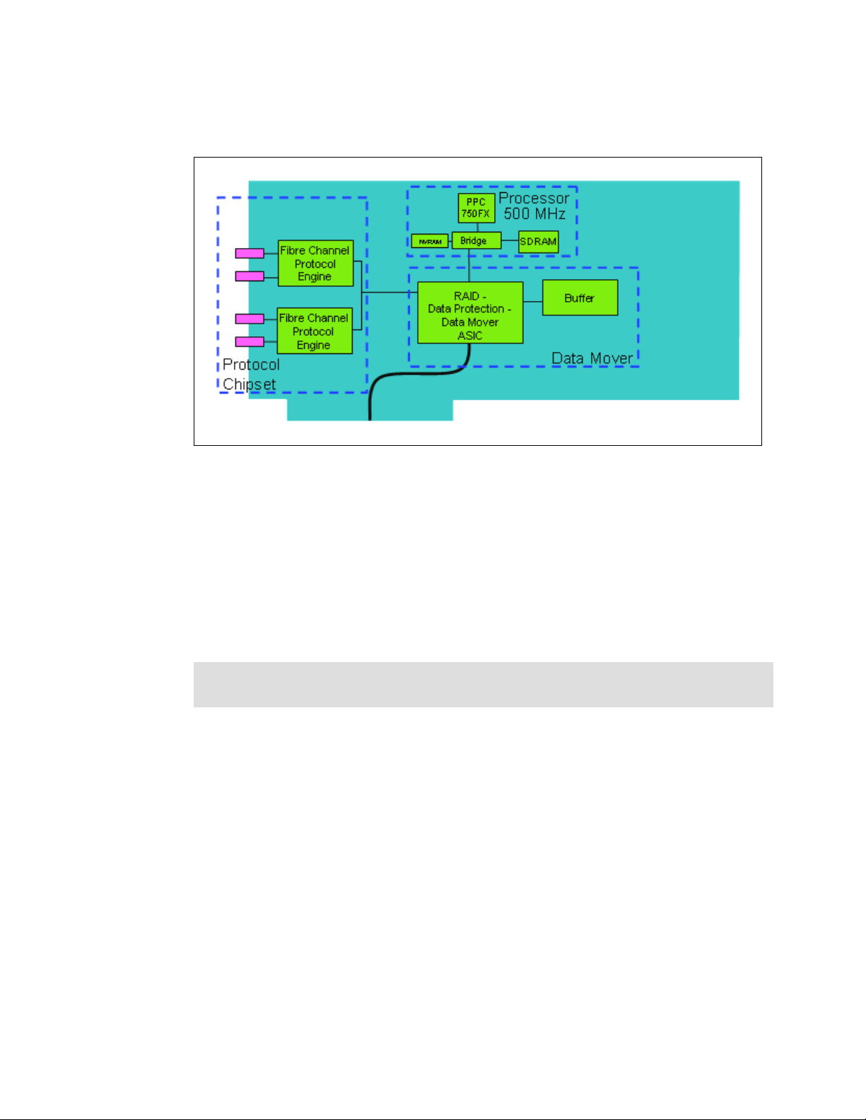
integrity it supports metadata creation and checking. The device adapter design is shown in
Figure 2-8.
Figure 2-8 DS8000 device adapter
The DAs are installed in pairs because each storage partition requires its own adapter to
connect to each disk enclosure for redundancy. This is why we refer to them as DA pairs.
2.4.2 Disk enclosures
Each DS8000 frame contains either 8 or 16 disk enclosures depending on whether it is a
base or expansion frame. Half of the disk enclosures are accessed from the front of the
frame, and half from the rear. Each DS8000 disk enclosure contains a total of 16 DDMs or
dummy carriers. A dummy carrier looks very similar to a DDM in appearance but contains no
electronics. The enclosure is pictured in Figure 2-9 on page 32.
Note: If a DDM is not present, its slot must be occupied by a dummy carrier. This is
because without a drive or a dummy, cooling air does not circulate correctly.
Each DDM is an industry standard FC-AL disk. Each disk plugs into the disk enclosure
backplane. The backplane is the electronic and physical backbone of the disk enclosure.
Chapter 2. Components 31
Page 54

Figure 2-9 DS8000 disk enclosure
Non-switched FC-AL drawbacks
In a standard FC-AL disk enclosure all of the disks are arranged in a loop, as depicted in
Figure 2-10. This loop-based architecture means that data flows through all disks before
arriving at either end of the device adapter (shown here as the
Figure 2-10 Industry standard FC-AL disk enclosure
The main problems with standard FC-AL access to DDMs are:
The full loop is required to participate in data transfer. Full discovery of the loop via LIP
(loop initialization protocol) is required before any data transfer. Loop stability can be
affected by DDM failures.
Storage Server).
In the event of a disk failure, it can be difficult to identify the cause of a loop breakage,
leading to complex problem determination.
There is a performance dropoff when the number of devices in the loop increases.
To expand the loop it is normally necessary to partially open it. If mistakes are made, a
complete loop outage can result.
32 DS8000 Series: Concepts and Architecture
Page 55

These problems are solved with the
switched FC-AL implementation on the DS8000.
Switched FC-AL advantages
The DS8000 uses switched FC-AL technology to link the device adapter (DA) pairs and the
DDMs. Switched FC-AL uses the standard FC-AL protocol, but the physical implementation is
different. The key features of switched FC-AL technology are:
Standard FC-AL communication protocol from DA to DDMs.
Direct point-to-point links are established between DA and DDM.
Isolation capabilities in case of DDM failures, providing easy problem determination.
Predictive failure statistics.
Simplified expansion; for example, no cable re-routing is required when adding another
disk enclosure.
The DS8000 architecture employs dual redundant switched FC-AL access to each of the disk
enclosures. The key benefits of doing this are:
Two independent networks to access the disk enclosures.
Four access paths to each DDM.
Each device adapter port operates independently.
Double the bandwidth over traditional FC-AL loop implementations.
In Figure 2-11 each DDM is depicted as being attached to two separate Fibre Channel
switches. This means that with two device adapters, we have four effective data paths to each
disk, each path operating at 2Gb/sec. Note that this diagram shows one switched disk
network attached to each DA. Each DA can actually support two switched networks.
Fibre channel switch
server 0
device
adapter
server 1
device
adapter
Fibre channel switch
Figure 2-11 DS8000 disk enclosure
When a connection is made between the device adapter and a disk, the connection is a
switched connection that uses arbitrated loop protocol. This means that a mini-loop is created
between the device adapter and the disk. Figure 2-12 on page 34 depicts four simultaneous
and independent connections, one from each device adapter port.
Chapter 2. Components 33
Page 56

Switched connections
server 0
Fibre channel switch
device
adapter
server 1
device
adapter
Fibre channel switch
Figure 2-12 Disk enclosure switched connections
DS8000 switched FC-AL implementation
For a more detailed look at how the switched disk architecture expands in the DS8000 you
should refer to Figure 2-13 on page 35. It depicts how each DS8000 device adapter connects
to two disk networks called loops. Expansion is achieved by adding enclosures to the
expansion ports of each switch. Each loop can potentially have up to six enclosures, but this
will vary depending on machine model and DA pair number. The front enclosures are those
that are physically located at the front of the machine. The rear enclosures are located at the
rear of the machine.
34 DS8000 Series: Concepts and Architecture
Page 57

Rear storage
enclosure N max=6
15
0
FC switch
Rear
enclosures
Server 0 device
adapter
Front
enclosures
Rear storage
enclosure 2
Rear storage
enclosure 1
Front storage
enclosure 1
Front storage
enclosure 2
Front storage
enclosure N max=6
15
0
15
0
0
15
0
15
0
15
8 or 16 DDMs per
enclosure
2Gbs FC-AL link
4 FC-AL Ports
Server 1 device
adapter
Figure 2-13 DS8000 switched disk expansion
Expansion
Expansion enclosures are added in pairs and disks are added in groups of 16. On the ESS
Model 800, the term 8-pack was used to describe an enclosure with eight disks in it. For the
DS8000, we use the term 16-pack, though this term really describes the 16 DDMs found in
one disk enclosure. It takes two orders of 16 DDMs to fully populate a disk enclosure pair
(front and rear).
To provide an example, if a machine had six disk enclosures total, it would have three at the
front and three at the rear. If all the enclosures were fully populated with disks, and an
additional order of 16 DDMs was purchased, then two new disk enclosures would be added,
one at the front and one at the rear. The switched networks do not need to be
these enclosures. They are simply added to the end of the
go in the front enclosure and half would go in the rear enclosure. If an additional 16 DDMs
were ordered later, they would be used to completely fill that pair of disk enclosures.
Arrays and spares
Array sites containing eight DDMs are created as DDMs are installed. During configuration,
discussed in Chapter 10, “The DS Storage Manager - logical configuration” on page 189, the
user will have the choice of creating a RAID-5 or RAID-10 array by choosing one array site.
The first four array sites created on a DA pair each contribute one DDM to be a spare. So at
least four spares are created per DA pair, depending on the disk intermix.
broken to add
loop. Half of the 16 DDMs would
Chapter 2. Components 35
Page 58

The intention is to only have four spares per DA pair, but this number may increase depending
on DDM intermix. We need to have four DDMs of the largest capacity and at least two DDMs
of the fastest RPM. If all DDMs are the same size and RPM, then four spares will be sufficient.
Arrays across loops
Each array site consists of eight DDMs. Four DDMs are taken from the front enclosure in an
enclosure pair, and four are taken from the rear enclosure in the pair. This means that when a
RAID array is created on the array site, half of the array is on each enclosure. Because the
front enclosures are on one switched loop, and the rear enclosures are on a second switched
loop, this splits the array across two loops. This is called
To better understand AAL refer to Figure 2-14 and Figure 2-15. To make the diagrams clearer,
only 16 DDMs are shown, eight in each disk enclosure. When fully populated, there would be
16 DDMs in each enclosure. Regardless, the diagram represents a valid configuration.
Figure 2-14 is used to depict the device adapter pair layout. One DA pair creates two switched
loops. The front enclosures populate one loop while the rear enclosures populate the other
loop. Each enclosure places two switches onto each loop. Each enclosure can hold up to 16
DDMs. DDMs are purchased in groups of 16. Half of the new DDMs go into the front
enclosure and half go into the rear enclosure.
array across loops (AAL).
Device adapter pair
loop 0
Server
0
device
adapter
loop 1
Figure 2-14 DS8000 switched loop layout
Fibre channel switch 1
Front enclosure
Rear enclosure
4
loop 0
2
Server
1
device
adapter
3
loop 1
There are two separate
switches in each enclosure.
Having established the physical layout, the diagram is now changed to reflect the layout of the
array sites, as shown in Figure 2-15 on page 37. Array site 0 in green (the darker disks) uses
the four left-hand DDMs in each enclosure. Array site 1 in yellow (the lighter disks), uses the
four right-hand DDMs in each enclosure. When an array is created on each array site, half of
36 DS8000 Series: Concepts and Architecture
Page 59

loop 0
the array is placed on each loop. If the disk enclosures were fully populated with DDMs, there
would be four array sites.
Fibre channel switch 1
loop 0
2
Server
0
device
adapter
loop 1
Server
Array site 0
Array site 1
1
device
adapter
3
loop 1
4
There are two separate
switches in each enclosure.
Figure 2-15 Array across loop
AAL benefits
AAL is used to increase performance. When the device adapter writes a stripe of data to a
RAID-5 array, it sends half of the write to each switched loop. By splitting the workload in this
manner, each loop is worked evenly, which improves performance. If RAID-10 is used, two
RAID-0 arrays are created. Each loop hosts one RAID-0 array. When servicing read I/O, half
of the reads can be sent to each loop, again improving performance by balancing workload
across loops.
DDMs
Each DDM is hot plugable and has two indicators. The green indicator shows disk activity
while the amber indicator is used with light path diagnostics to allow for easy identification and
replacement of a failed DDM.
At present the DS8000 allows the choice of three different DDM types:
73 GB, 15K RPM drive
146 GB, 10K RPM drive
300 GB, 10K RPM drive
2.5 Host adapters
The DS8000 supports two types of host adapters: ESCON and Fibre Channel/FICON. It does
not support SCSI adapters.
Chapter 2. Components 37
Page 60

The ESCON adapter in the DS8000 is a dual ported host adapter for connection to older
zSeries hosts that do not support FICON. The ports on the ESCON card use the MT-RJ type
connector.
Control units and logical paths
ESCON architecture recognizes only 16 3990 logical control units (LCUs) even though the
DS8000 is capable of emulating far more (these extra control units can be used by FICON).
Half of the LCUs (even numbered) are in server 0, and the other half (odd-numbered) are in
server 1. Because the ESCON host adapters can connect to both servers, each adapter can
address all 16 LCUs.
An ESCON link consists of two fibers, one for each direction, connected at each end by an
ESCON connector to an ESCON port. Each ESCON adapter card supports two ESCON
ports or links, and each link supports 64 logical paths.
ESCON distances
For connections without repeaters, the ESCON distances are 2 km with 50 micron multimode
fiber, and 3 km with 62.5 micron multimode fiber. The DS8000 supports all models of the IBM
9032 ESCON directors that can be used to extend the cabling distances.
Remote Mirror and Copy with ESCON
The initial implementation of the ESS 2105 Remote Mirror and Copy function (better known
as PPRC or Peer-to-Peer Remote Copy) used ESCON adapters. This was known as PPRC
Version 1. The ESCON adapters in the DS8000 do not support any form of Remote Mirror
and Copy. If you wish to create a remote mirror between a DS8000 and an ESS 800 or
another DS8000 or DS6000, you must use Fibre Channel adapters. You cannot have a
remote mirror relationship between a DS8000 and an ESS E20 or F20 because the E20/F20
only support Remote Mirror and Copy over ESCON.
ESCON supported servers
ESCON is used for attaching the DS8000 to the IBM S/390 and zSeries servers. The most
current list of supported servers is at this Web site:
http://www.storage.ibm.com/hardsoft/products/DS8000/supserver.htm
This site should be consulted regularly because it has the most up-to-date information on
server attachment support.
2.5.1 FICON and Fibre Channel protocol host adapters
Fibre Channel is a technology standard that allows data to be transferred from one node to
another at high speeds and great distances (up to 10 km and beyond). The DS8000 uses
Fibre Channel protocol to transmit SCSI traffic inside Fibre Channel frames. It also uses Fibre
Channel to transmit FICON traffic, which uses Fibre Channel frames to carry zSeries I/O.
Each DS8000 Fibre Channel card offers four 2 Gbps Fibre Channel ports. The cable
connector required to attach to this card is an LC type. Each port independently
auto-negotiates to either 2 Gbps or 1 Gbps link speed. Each of the 4 ports on one DS8000
adapter can also independently be either Fibre Channel protocol (FCP) or FICON, though the
ports are initially defined as switched point to point FCP. Selected ports will be configured to
FICON automatically based on the definition of a FICON host. Each port can be either FICON
or Fibre Channel protocol (FCP). The personality of the port is changeable via the DS
Storage Manager GUI. A port cannot be both FICON and FCP simultaneously, but it can be
changed as required.
38 DS8000 Series: Concepts and Architecture
Page 61

The card itself is PCI-X 64 Bit 133 MHz. The card is driven by a new high function, high
performance ASIC. To ensure maximum data integrity, it supports metadata creation and
checking. Each Fibre Channel port supports a maximum of 509 host login IDs. This allows for
the creation of very large storage area networks (SANs). The design of the card is depicted in
Figure 2-16.
Processor
Protocol
QDR
Fibre Channel
Protocol
Engine
Fibre Channel
Protocol
Engine
QDR
PPC
750GX
Data Protection
Data Mover
ASIC
1 GHz
Buffer
Flash
Data Mover
Chipset
Figure 2-16 DS8000 FICON/FCP host adapter
Fibre Channel supported servers
The current list of servers supported by the Fibre Channel attachment is at this Web site:
http://www.storage.ibm.com/hardsoft/products/DS8000/supserver.htm
This document should be consulted regularly because it has the most up-to-date information
on server attachment support.
Fibre Channel distances
There are two types of host adapter cards you can select: long wave and short wave. With
long-wave laser, you can connect nodes at distances of up to 10 km (non-repeated). With
short wave you are limited to a distance of 300 to 500 metres (non-repeated). All ports on
each card must be either long wave or short wave (there can be no mixing of types within a
card).
2.6 Power and cooling
The DS8000 power and cooling system is highly redundant.
Rack Power Control cards (RPC)
The DS8000 has a pair of redundant RPC cards that are used to control certain aspects of
power sequencing throughout the DS8000. These cards are attached to the Service
Processor (SP) card in each processor, which allows them to communicate both with the
Storage Hardware Management Console (S-HMC) and the storage facility image LPARs. The
RPCs also communicate with each primary power supply and indirectly with each rack’s fan
sense cards and the disk enclosures in each frame.
Chapter 2. Components 39
Page 62

Primary power supplies
The DS8000 primary power supply (PPS) converts input AC voltage into DC voltage. There
are high and low voltage versions of the PPS because of the varying voltages used
throughout the world. Also, because the line cord connector requirements vary widely
throughout the world, the line cord may not come with a suitable connector for your nation’s
preferred outlet. This may need to be replaced by an electrician once the machine is
delivered.
There are two redundant PPSs in each frame of the DS8000. Each PPS is capable of
powering the frame by itself. The PPS creates 208V output power for the processor complex
and I/O enclosure power supplies. It also creates 5V and 12V DC power for the disk
enclosures. There may also be an optional booster module that will allow the PPSs to
temporarily run the disk enclosures off battery, if the extended power line disturbance feature
has been purchased (see Chapter 4, “RAS” on page 61, for a complete explanation as to why
this feature may or may not be necessary for your installation).
Each PPS has internal fans to supply cooling for that power supply.
Processor and I/O enclosure power supplies
Each processor and I/O enclosure has dual redundant power supplies to convert 208V DC
into the required voltages for that enclosure or complex. Each enclosure also has its own
cooling fans.
Disk enclosure power and cooling
The disk enclosures do not have separate power supplies since they draw power directly from
the PPSs. They do, however, have cooling fans located in a plenum above the enclosures.
They draw cooling air through the front of each enclosure and exhaust air out of the top of the
frame.
Battery backup assemblies
The backup battery assemblies help protect data in the event of a loss of external power. The
model 921 contains two battery backup assemblies while the model 922 and 9A2 contain
three of them (to support the 4-way processors). In the event of a complete loss of input AC
power, the battery assemblies are used to allow the contents of NVS memory to be written to
a number of DDMs internal to the processor complex, prior to power off.
The FC-AL DDMs are not protected from power loss unless the extended power line
disturbance feature has been purchased.
2.7 Management console network
All base models ship with one Storage Hardware Management Console (S-HMC), a keyboard
and display, plus two Ethernet switches.
S-HMC
The S-HMC is the focal point for configuration, Copy Services management, and
maintenance activities. It is possible to order two management consoles to act as a redundant
pair. A typical configuration would be to have one internal and one external management
console. The internal S-HMC will contain a PCI modem for remote service.
40 DS8000 Series: Concepts and Architecture
Page 63

Ethernet switches
In addition to the Fibre Channel switches installed in each disk enclosure, the DS8000 base
frame contains two 16-port Ethernet switches. Two switches are supplied to allow the
creation of a fully redundant management network. Each processor complex has multiple
connections to each switch. This is to allow each server to access each switch. This switch
cannot be used for any equipment not associated with the DS8000. The switches get power
from the internal power bus and thus do not require separate power outlets.
2.8 Summary
This chapter has described the various components that make up a DS8000. For additional
information, there is documentation available at:
http://www-1.ibm.com/servers/storage/support/disk/index.html
Chapter 2. Components 41
Page 64

42 DS8000 Series: Concepts and Architecture
Page 65

3
Chapter 3. Storage system LPARs (Logical
partitions)
This chapter provides information about storage system Logical Partitions (LPARs) in the
DS8000.
The following topics are discussed in detail:
Introduction to LPARs
DS8000 and LPARs
– LPAR and storage facility images (SFIs)
– DS8300 LPAR implementation
– Hardware components of a storage facility image
– DS8300 Model 9A2 configuration options
LPAR security and protection
LPAR and Copy Services
LPAR benefits
© Copyright IBM Corp. 2005. All rights reserved. 43
Page 66

3.1 Introduction to logical partitioning
Logical partitioning allows the division of a single server into several completely independent
virtual servers or partitions.
IBM began work on logical partitioning in the late 1960s, using S/360 mainframe systems with
the precursors of VM, specifically CP40. Since then, logical partitioning on IBM mainframes
(now called IBM zSeries) has evolved from a predominantly physical partitioning scheme
based on hardware boundaries to one that allows for virtual and shared resources with
dynamic load balancing. In 1999 IBM implemented LPAR support on the AS/400 (now called
IBM iSeries) platform and on pSeries in 2001. In 2000 IBM announced the ability to run the
Linux operating system in an LPAR or on top of VM on a zSeries server, to create thousands
of Linux instances on a single system.
3.1.1 Virtualization Engine technology
IBM Virtualization Engine is comprised of a suite of system services and technologies that
form key elements of IBM’s on demand computing model. It treats resources of individual
servers, storage, and networking products as if in a single pool, allowing access and
management of resources across an organization more efficiently. Virtualization is a critical
component in the on demand operating environment. The system technologies implemented
in the POWER5 processor provide a significant advancement in the enablement of functions
required for operating in this environment.
LPAR is one component of the POWER5 system technology that is part of the IBM
Virtualization Engine.
Using IBM Virtualization Engine technology, selected models of the DS8000 series can be
used as a single, large storage system, or can be used as multiple storage systems with
logical partitioning (LPAR) capabilities. IBM LPAR technology, which is unique in the storage
industry, allows the resources of the storage system to be allocated into separate logical
storage system partitions, each of which is totally independent and isolated. Virtualization
Engine (VE) delivers the capabilities to simplify the infrastructure by allowing the
management of heterogeneous partitions/servers on a single system.
3.1.2 Partitioning concepts
It is appropriate to clarify the terms and definitions by which we classify these mechanisms.
Note: The following sections discuss partitioning concepts in general and not all are
applicable to the DS8000.
Partitions
When a multi-processor computer is subdivided into multiple, independent operating system
images, those independent operating environments are called partitions. The resources on
the system are allocated to specific partitions.
Resources
Resources are defined as a system’s processors, memory, and I/O slots. I/O slots can be
populated by different adapters, such as Ethernet, SCSI, Fibre Channel or other device
controllers. A disk is allocated to a partition by assigning it the I/O slot that contains the disk’s
controller.
44 DS8000 Series: Concepts and Architecture
Page 67

Building block
A building block is a collection of system resources, such as processors, memory, and I/O
connections.
Physical partitioning (PPAR)
In physical partitioning, the partitions are divided along hardware boundaries. Each partition
might run a different version of the same operating system. The number of partitions relies on
the hardware. Physical partitions have the advantage of allowing complete isolation of
operations from operations running on other processors, thus ensuring their availability and
uptime. Processors, I/O boards, memory, and interconnects are not shared, allowing
applications that are business-critical or for which there are security concerns to be
completely isolated. The disadvantage of physical partitioning is that machines cannot be
divided into as many partitions as those that use logical partitioning, and users can't
consolidate many lightweight applications on one machine.
Logical partitioning (LPAR)
A logical partition uses hardware and firmware to logically partition the resources on a
system. LPARs logically separate the operating system images, so there is not a dependency
on the hardware building blocks.
A logical partition consists of processors, memory, and I/O slots that are a subset of the pool
of available resources within a system, as shown in Figure 3-1 on page 46. While there are
configuration rules, the granularity of the units of resources that can be allocated to partitions
is very flexible. It is possible to add just a small amount of memory, if that is all that is needed,
without a dependency on the size of the memory controller or without having to add more
processors or I/O slots that are not needed.
LPAR differs from physical partitioning in the way resources are grouped to form a partition.
Logical partitions do not need to conform to the physical boundaries of the building blocks
used to build the server. Instead of grouping by physical building blocks, LPAR adds more
flexibility to select components from the entire pool of available system resources.
Chapter 3. Storage system LPARs (Logical partitions) 45
Page 68

Logical Partition
Logical
Partition 0
Processor
Cache
I/O I/O I/O I/O I/O I/O I/O I/O I/O I/O I/O I/O
Figure 3-1 Logical partition
Logical Partition 1 Logical Partition 2
Processor
Cache
Processor
Cache
Processor
Cache
Processor
Cache
Processor
Memory
hardware management console
Cache
Software and hardware fault isolation
Because a partition hosts an independent operating system image, there is strong software
isolation
. This means that a job or software crash in one partition will not effect the resources
in another partition.
Dynamic logical partitioning
Starting from AIX 5L™ Version 5.2, IBM supports dynamic logical partitioning (also known as
DLPAR) in partitions on several logical partitioning capable IBM pSeries server models.
The dynamic logical partitioning function allows resources, such as CPUs, memory, and I/O
slots, to be added to or removed from a partition, as well as allowing the resources to be
moved between two partitions, without an operating system reboot (
on the fly).
Micro-Partitioning™
With AIX 5.3, partitioning capabilities are enhanced to include sub-processor partitioning, or
Micro-Partitioning. With Micro-Partitioning it is possible to allocate less than a full physical
processor to a logical partition.
The benefit of Micro-Partitioning is that it allows increased overall utilization of system
resources by automatically applying only the required amount of processor resource needed
by each partition.
Virtual I/O
On POWER5 servers, I/O resources (disks and adapters) can be shared through Virtual I/O.
Virtual I/O provides the ability to dedicate I/O adapters and devices to a virtual server,
46 DS8000 Series: Concepts and Architecture
Page 69

allowing the on-demand allocation of those resources to different partitions and the
management of I/O devices. The physical resources are owned by the Virtual I/O server.
3.1.3 Why Logically Partition?
There is a demand to provide greater flexibility for high-end systems, particularly the ability to
subdivide them into smaller partitions that are capable of running a version of an operating
system or a specific set of application workloads.
The main reasons for partitioning a large system are as follows:
Server consolidation
A highly reliable server with sufficient processing capacity and capable of being partitioned
can address the need for server consolidation by logically subdividing the server into a
number of separate, smaller systems. This way, the application isolation needs can be met in
a consolidated environment, with the additional benefits of reduced floor space, a single point
of management, and easier redistribution of resources as workloads change. Increasing or
decreasing the resources allocated to partitions can facilitate better utilization of a server that
is exposed to large variations in workload.
Production and test environments
Generally, production and test environments should be isolated from each other. Without
partitioning, the only practical way of performing application development and testing is to
purchase additional hardware and software.
Partitioning is a way to set aside a portion of the system resources to use for testing new
versions of applications and operating systems, while the production environment continues
to run. This eliminates the need for additional servers dedicated to testing, and provides more
confidence that the test versions will migrate smoothly into production because they are
tested on the production hardware system.
Consolidation of multiple versions of the same OS or applications
The flexibility inherent in LPAR greatly aids the scheduling and implementation of normal
upgrade and system maintenance activities. All the preparatory activities involved in
upgrading an application or even an operating system could be completed in a separate
partition. An LPAR can be created to test applications under new versions of the operating
system prior to upgrading the production environments. Instead of having a separate server
for this function, a minimum set of resources can be temporarily used to create a new LPAR
where the tests are performed. When the partition is no longer needed, its resources can be
incorporated back into the other LPARs.
Application isolation
Partitioning isolates an application from another in a different partition. For example, two
applications on one symmetric multi-processing (SMP) system could interfere with each other
or compete for the same resources. By separating the applications into their own partitions,
they cannot interfere with each other. Also, if one application were to hang or crash the
operating system, this would not have an effect on the other partitions. Also, applications are
prevented from consuming excess resources, which could starve other applications of
resources they require.
Increased hardware utilization
Partitioning is a way to achieve better hardware utilization when software does not scale well
across large numbers of processors. Where possible, running multiple instances of an
Chapter 3. Storage system LPARs (Logical partitions) 47
Page 70

application on separate smaller partitions can provide better throughput than running a single
large instance of the application.
Increased flexibility of resource allocation
A workload with resource requirements that change over time can be managed more easily
within a partition that can be altered to meet the varying demands of the workload.
3.2 DS8000 and LPAR
In the first part of this chapter we discussed the LPAR features in general. In this section we
provide information on how the LPAR functionality is implemented in the DS8000 series.
The DS8000 series is a server-based disk storage system. With the integration of the
POWER5 eServer p5 570 into the DS8000 series, IBM offers the first implementation of the
server LPAR functionality in a disk storage system.
The storage system LPAR functionality is currently supported in the DS8300 Model 9A2. It
provides two virtual storage systems in one physical machine. Each storage system LPAR
can run its own level of licensed internal code (LIC).
The resource allocation for processors, memory, and I/O slots in the two storage system
LPARs on the DS8300 is currently divided into a fixed ratio of 50/50.
Note: The allocation for resources will be more flexible. According to the announcement
letter IBM has issued a Statement of General Direction:
IBM intends to enhance the Virtualization Engine partitioning capabilities of selected
models of the DS8000 series to provide greater flexibility in the allocation and
management of resources between images.
Between the two storage facility images there exists a robust isolation via hardware; for
example, separated RIO-G loops, and the POWER5 Hypervisor, which is described in more
detail in section 3.3, “LPAR security through POWER™ Hypervisor (PHYP)” on page 54.
3.2.1 LPAR and storage facility images
Before we start to explain how the LPAR functionality is implemented in the DS8300, we want
to clarify some terms and naming conventions. Figure 3-2 on page 49 illustrates these terms.
48 DS8000 Series: Concepts and Architecture
Page 71

Processor
Processor
complex 0
complex 1
Storage
LPAR01 LPAR11
Facility
Image 1
Storage
LPAR02
Facility
LPAR12
Image 2
LPARxy
x=Processor complex number
y=Storage facility number
Figure 3-2 DS8300 Model 9A2 - LPAR and storage facility image
The DS8300 series incorporates two eServer p5 570s. We call each of these a processor
complex
complex on the DS8300 is divided into two LPARs. An
processor complex that support the execution of an operating system. The
image
. Each processor complex supports one or more LPARs. Currently each processor
LPAR is a set of resources on a
storage facility
is built from a pair of LPARs, one on each processor complex.
Figure 3-2 shows that LPAR01 from processor complex 0 and LPAR11 from processor
complex 1 instantiate storage facility image 1. LPAR02 from processor complex 0 and
LPAR12 from processor complex 1 instantiate the second storage facility image.
Important: It is important to understand that an LPAR in a processor complex is not the
same as a storage facility image in the DS8300.
3.2.2 DS8300 LPAR implementation
Each storage facility image will use the machine type/model number/serial number of the
DS8300 Model 9A2 base frame. The frame serial number will end with
of the serial number will be replaced by a number in the range
identifies the DS8000 image. Initially, this character will be a
two storage facility images available. The serial number is needed to distinguish between the
storage facility images in the GUI, CLI, and for licensing and allocating the licenses between
the storage facility images.
The first release of the LPAR functionality in the DS8300 Model 9A2 provides a split between
the resources in a 50/50 ratio as depicted in Figure 3-3 on page 50.
0. The last character
one to eight that uniquely
1or a 2, because there are only
Chapter 3. Storage system LPARs (Logical partitions) 49
Page 72

Processor complex 0
Storage
enclosures
Processor complex 1
Storage
Facility
RIO-G RIO-G
I/O drawers
Image 1
(LPAR01) (LPAR11)
Storage
RIO-G RIO-G
I/O drawers
Facility
Image 2
(LPAR02) (LPAR12)
enclosures
Figure 3-3 DS8300 LPAR resource allocation
Each storage facility image has access to:
50 percent of the processors
50 percent of the processor memory
Storage
Facility
Image 1
Storage
Facility
Image 2
Storage
1 loop of the RIO-G interconnection
Up to 16 host adapters (4 I/O drawers with up to 4 host adapters)
Up to 320 disk drives (up to 96 TB of capacity)
3.2.3 Storage facility image hardware components
In this section we explain which hardware resources are required to build a storage facility
image.
The management of the resource allocation between LPARs on a pSeries is done via the
Storage Hardware Management Console (S-HMC). Because the DS8300 Model 9A2
provides a fixed split between the two storage facility images, there is no management or
configuration necessary via the S-HMC. The DS8300 comes pre-configured with all required
LPAR resources assigned to either storage facility image.
Figure 3-4 on page 51 shows the split of all available resources between the two storage
facility images. Each storage facility image has 50% of all available resources.
50 DS8000 Series: Concepts and Architecture
Page 73

Storage Facility Image 1
Processors2 Processors
Memory
AA'
boot
data data
boot
data data
RIO-G interface
RIO-G interface
RIO-G interface
SCSI controller
Ethernet-Port
HA DAHA HA HADA
I/O drawer
0
HA DAHA HA HADA
I/O drawer
1
Processor complex 1Processor complex 0Processor complex 0
RIO-G interface
RIO-G interface
RIO-G interface
SCSI controller
Ethernet -Port
Ethernet -Port
Processors2 Processors
Memory
BB'
boot
data data
boot
data data
S-HMC
CD/DVD
CC'
boot
boot
data data
Memory
2 Processors
data data
Ethernet-Port
SCSI controller
RIO-G interface
RIO-G interface
RIO-G interface
HA DAHA HA HADA
HA DAHA HA HADA
I/O drawer
Ethernet -Port
Ethernet-Port
SCSI controller
3
SCSI controller
RIO-G interface
RIO-G interface
RIO-G interface
RIO-G interface
DD'
boot
data data
Memory
2 Processors
boot
data data
I/O drawer
2
Storage Facility Image 2
Figure 3-4 Storage facility image resource allocation in the processor complexes of the DS8300
I/O resources
For one storage facility image, the following hardware resources are required:
2 SCSI controllers with 2 disk drives each
CD/DVD
2 Ethernet ports (to communicate with the S-HMC)
1 Thin Device Media Bay (for example, CD or DVD; can be shared between the LPARs)
Each storage facility image will have two physical disk drives in each processor complex.
Each disk drive will contain three logical volumes, the boot volume and two logical volumes
for the memory save dump function. These three logical volumes are then mirrored across the
two physical disk drives for each LPAR. In Figure 3-4, for example, the disks A/A' are mirrors.
For the DS8300 Model 9A2, there will be four drives total in one physical processor complex.
Processor and memory allocations
In the DS8300 Model 9A2 each processor complex has four processors and up to 128 GB
memory. Initially there is also a 50/50 split for processor and memory allocation.
Therefore, every LPAR has two processors and so every storage facility image has four
processors.
The memory limit depends on the total amount of available memory in the whole system.
Currently there are the following memory allocations per storage facility available:
32 GB (16 GB per processor complex, 16 GB per storage facility image)
64 GB (32 GB per processor complex, 32 GB per storage facility image)
128 GB (64 GB per processor complex, 64 GB per storage facility image)
256 GB (128 GB per processor complex, 128 GB per storage facility image)
Chapter 3. Storage system LPARs (Logical partitions) 51
Page 74

RIO-G interconnect separation
Figure 3-4 on page 51 depicts that the RIO-G interconnection is also split between the two
storage facility images. The RIO-G interconnection is divided into 2 loops. Each RIO-G loop is
dedicated to a given storage facility image. All I/O enclosures on the RIO-G loop with the
associated host adapters and drive adapters are dedicated to the storage facility image that
owns the RIO-G loop.
As a result of the strict separation of the two images, the following configuration options exist:
Each storage facility image is assigned to one dedicated RIO-G loop; if an image is offline,
its RIO-G loop is not available.
All I/O enclosures on a given RIO-G loop are dedicated to the image that owns the RIO-G
loop.
Host adapter and device adapters on a given loop are dedicated to the associated image
that owns this RIO-G loop.
Disk enclosures and storage devices behind a given device adapter pair are dedicated to
the image that owns the RIO-G loop.
Configuring of capacity to an image is managed through the placement of disk enclosures
on a specific DA pair dedicated to this image.
3.2.4 DS8300 Model 9A2 configuration options
In this section we explain which configuration options are available for the DS8300 Model
9A2.
The Model 9A2 (base frame) has:
32 to 128 DDMs
– Up to 64 DDMs per storage facility image, in increments of 16 DDMs
System memory
– 32, 64, 128, 256 GB (half of the amount of memory is assigned to each storage facility
image)
Four I/O bays
– Two bays assigned to storage facility image 1 and two bays assigned to storage facility
image 2
– Each bay contains:
• Up to 4 host adapters
• Up to 2 device adapters
S-HMC, keyboard/display, and 2 Ethernet switches
The first Model 9AE (expansion frame) has:
An additional four I/O bays
Two bays are assigned to storage facility image 1 and two bays are assigned to storage
facility image 2.
Each bay contains:
– Up to 4 host adapters
– Up to 2 device adapters
52 DS8000 Series: Concepts and Architecture
Page 75

An additional 256 DDMs
– Up to 128 DDMs per storage facility image
The second Model 9AE (expansion frame) has:
An additional 256 DDMs
– Up to 128 drives per storage facility image
A fully configured DS8300 with storage facility images has one base frame and two expansion
frames. The first expansion frame (9AE) has additional I/O drawers and disk drive modules
(DDMs), while the second expansion frame contains additional DDMs.
Figure 3-5 provides an example of how a fully populated DS8300 might be configured. The
disk enclosures are assigned to storage facility image 1 (yellow, or lighter if not viewed in
color) or storage facility image 2 (green, or darker). When ordering additional disk capacity, it
can be allocated to either storage facility image 1 or storage facility image 2. The cabling is
pre-determined and in this example there is an empty pair of disk enclosures assigned for the
next increment of disk to be added to storage facility image 2.
Storage
Facility
Image 1
Storage
Facility
Image 1
I/O drawer
0
I/O drawer
2
Storage
enclosure
Storage
enclosure
Storage
enclosure
Storage
enclosure
Processor
complex 0
Processor
complex 1
Storage
Facility
Image 2
Storage
Facility
Image 2
I/O drawer
1
I/O drawer
3
I/O draw er
4
I/O draw er
6
Storage
enclosure
Storage
enclosure
Storage
enclosure
Storage
enclosure
Storage
enclosure
Storage
enclosure
Storage
enclosure
Storage
enclosure
Storage
enclosure
Storage
enclosure
Storage
enclosure
Storage
enclosure
Empty storage
enclosure
Empty storage
enclosure
Storage
enclosure
Storage
enclosure
I/O drawer
5
I/O drawer
7
Figure 3-5 DS8300 example configuration
Model conversion
The Model 9A2 has a fixed 50/50 split into two storage facility images. However, there are
various model conversions available. For example, it is possible to switch from Model 9A2 to a
full system machine, which is the Model 922. Table 3-1 shows all possible model conversions
regarding the LPAR functionality.
Chapter 3. Storage system LPARs (Logical partitions) 53
Page 76

Table 3-1 Model conversions regarding LPAR functionality
From Model To Model
921 (2-way processors without LPAR) 9A2 (4-way processors with LPAR)
922 (4-way processors without LPAR) 9A2 (4-way processors with LPAR)
9A2 (4-way processors with LPAR) 922 (4-way processors without LPAR)
92E (expansion frame without LPAR) 9AE (expansion frame with LPAR)
9AE (expansion frame with LPAR) 92E (expansion frame without LPAR)
Note: Every model conversion is a disruptive operation.
3.3 LPAR security through POWER™ Hypervisor (PHYP)
The DS8300 Model 9A2 provides two storage facility images. This offers a number of
desirable business advantages. But it also can raise some concerns about security and
protection of the storage facility images in the DS8000 series. In this section we explain how
the DS8300 delivers robust isolation between the two storage facility images.
One aspect of LPAR protection and security is that the DS8300 has a dedicated allocation of
the hardware resources for the two facility images. There is a clear split of processors,
memory, I/O slots, and disk enclosures between the two images.
Another important security feature which is implemented in the pSeries server is called the
POWER Hypervisor (PHYP). It enforces partition integrity by providing a security layer
between logical partitions. The POWER Hypervisor is a component of system firmware that
will always be installed and activated, regardless of the system configuration. It operates as a
hidden partition, with no processor resources assigned to it.
Figure 3-6 on page 55 illustrates a set of address mapping mechanisms which are described
in the following paragraphs.
In a partitioned environment, the POWER Hypervisor is loaded into the first Physical Memory
Block (PMB) at the physical address zero and reserves the PMB. From then on, it is not
possible for an LPAR to access directly the physical memory. Every memory access is
controlled by the POWER Hypervisor.
Each partition has its own exclusive page table, which is also controlled by the POWER
Hypervisor. Processors use these tables to transparently convert a program's virtual address
into the physical address where that page has been mapped into physical memory.
In a partitioned environment, the operating system uses hypervisor services to manage the
translation control entry (TCE) tables. The operating system communicates the desired I/O
bus address to logical mapping, and the hypervisor translates that into the I/O bus address to
physical mapping within the specific TCE table. The hypervisor needs a dedicated memory
region for the TCE tables to translate the I/O address to the partition memory address, then
the hypervisor can perform direct memory access (DMA) transfers to the PCI adapters.
54 DS8000 Series: Concepts and Architecture
Page 77

LPAR Protection in IBM POWER5™ Hardware
HypervisorControlled
TCE Tables
For DMA
Partition 1
Proc
Proc
Proc
Partition 2
Proc
Proc
Proc
HypervisorControlled
Page Tables
N
N
N
Real Addresses
0
0
0
Real Addresses
Virtual Addresses
Virtual Addresses
Virtual Addresses
Virtual Addresses
I/O Load/Store
I/O Loa d/St ore
Physical
Memory
{
Addr N
Addr N
{
The Hardware and Hypervisor manage the real to virtual memory
mapping to provide robust isolation between partitions
Figure 3-6 LPAR protection - POWER Hypervisor
Addr 0
Addr 0
Partition 1
I/O Slot
I/O Slot
I/O Slot
Bus Addresses
Bus Addresses
I/O Slot
Partition 2
I/O Slot
I/O Slot
Bus Addresses
Bus Addresses
3.4 LPAR and Copy Services
In this section we provide some specific information about the Copy Services functions
related to the LPAR functionality on the DS8300. An example for this can be seen in
Figure 3-7 on page 56.
Chapter 3. Storage system LPARs (Logical partitions) 55
Page 78

DS8300 Storage Facility Images and Copy Services
ü
ü
Storage Facility Image 1
ü
ü
Storage Facility Image 1
PPRC
PPRC
Primary
Primary
PPRC
PPRC
Secondary
Secondary
PPRC
PPRC
Primary
Primary
Storage Facility Image 2
Storage Facility Image 2
PPRC
PPRC
Secondary
Secondary
FlashCopy
FlashCopy
Source
Source
FlashCopy
FlashCopy
Target
Target
FlashCopy
FlashCopy
Source
Source
üRemote Mirroring and Copy (PPRC) within a Storage Facility Image or across Storage Facility Images
üRemote Mirroring and Copy (PPRC) within a Storage Facility Image or across Storage Facility Images
üFlashCopy within a Storage Facility Image
üFlashCopy within a Storage Facility Image
Figure 3-7 DS8300 storage facility images and Copy Services
û
û
FlashCopy
FlashCopy
Target
Target
FlashCopy
The DS8000 series fully supports the FlashCopy V2 capabilities that the ESS Model 800
currently provides. One function of FlashCopy V2 was the ability to have the source and
target of a FlashCopy relationship reside anywhere within the ESS (commonly referred to as
cross LSS support). On a DS8300 Model 9A2, the source and target must reside within the
same storage facility image.
A source volume of a FlashCopy located in one storage facility image cannot have a target
volume in the second storage facility image, as illustrated in Figure 3-7.
Remote mirroring
A Remote Mirror and Copy relationship is supported across storage facility images. The
primary server could be located in one storage facility image and the secondary in another
storage facility image within the same DS8300.
For more information about Copy Services refer to Chapter 7, “Copy Services” on page 115.
3.5 LPAR benefits
The exploitation of the LPAR technology in the DS8300 Model 9A2 offers many potential
benefits. You get a reduction in floor space, power requirements, and cooling requirements
through consolidation of multiple stand-alone storage functions.
It helps you to simplify your IT infrastructure through a reduced system management effort.
You also can reduce your storage infrastructure complexity and your physical asset
management.
56 DS8000 Series: Concepts and Architecture
Page 79

The hardware-based LPAR implementation ensures data integrity. The fact that you can
create dual, independent, completely segregated virtual storage systems helps you to
optimize the utilization of your investment, and helps to segregate workloads and protect
them from one another.
The following are examples of possible scenarios where storage facility images would be
useful:
Two production workloads
The production environments can be split, for example, by operating system, application,
or organizational boundaries. For example, some customers maintain separate physical
ESS 800s with z/OS hosts on one and open hosts on the other. A DS8300 could maintain
this isolation within a single physical storage system.
Production and development partitions
It is possible to separate the production environment from a development partition. On one
partition you can develop and test new applications, completely segregated from a
mission-critical production workload running in another storage facility image.
Dedicated partition resources
As a service provider you could provide dedicated resources to each customer, thereby
satisfying security and service level agreements, while having the environment all
contained on one physical DS8300.
Production and data mining
For database purposes you can imagine a scenario where your production database is
running in the first storage facility image and a copy of the production database is running
in the second storage facility image. You can perform analysis and data mining on it
without interfering with the production database.
Business continuance (secondary) within the same physical array
You can use the two partitions to test Copy Services solutions or you can use them for
multiple copy scenarios in a production environment.
Information Lifecycle Management (ILM) partition with fewer resources, slower DDMs
One storage facility image can utilize, for example, only fast disk drive modules to ensure
high performance for the production environment, and the other storage facility image can
use fewer and slower DDMs to ensure Information Lifecycle Management at a lower cost.
Figure 3-8 on page 58 depicts one example for storage facility images in the DS8300.
Chapter 3. Storage system LPARs (Logical partitions) 57
Page 80

System 1
Open System
System 2
zSeries
Storage Facility Image 1
Capacity: 20 TB Fixed Block ( FB)
LIC level: A
License function: Point-in-time Co py
License feature: FlashCopy
LUN0
LUN1
LUN2
DS8300 Model 9A2
(Physical Capacity: 30 TB)
3390-3
3390-3
Storage Facility Image 2
Capacity: 10 TB Count Key Data ( CKD)
LIC level: B
License function: no Copy function
License feature: no Copy feature
Figure 3-8 Example of storage facility images in the DS8300
This example shows a DS8300 with a total physical capacity of 30 TB. In this case, a
minimum Operating Environment License (OEL) is required to cover the 30 TB capacity. The
DS8300 is split into two storage facility images. Storage facility image 1 is used for an Open
System environment and utilizes 20 TB of fixed block data. Storage facility image 2 is used for
a zSeries environment and uses 10 TB of count key data.
To utilize FlashCopy on the entire capacity would require a 30 TB FlashCopy license.
However, as in this example, it is possible to have a FlashCopy license for storage facility
image 1 for 20 TB only. In this example for the zSeries environment, no copy function is
needed, so there is no need to purchase a Copy Services license for storage facility image 2.
You can find more information about the licensed functions in 9.3, “DS8000 licensed
functions” on page 167.
This example also shows the possibility of running two different licensed internal code (LIC)
levels in the storage facility images.
Addressing capabilities with storage facility images
Figure 3-9 on page 59 highlights the enormous enhancements of the addressing capabilities
that you get with the DS8300 in LPAR mode in comparison to the previous ESS Model 800.
58 DS8000 Series: Concepts and Architecture
Page 81

DS8300 addressing capabilities
Figure 3-9 Comparison with ESS Model 800 and DS8300 with and without LPAR
3.6 Summary
The DS8000 series delivers the first use of the POWER5 processor IBM Virtualization Engine
logical partitioning capability. This storage system LPAR technology is designed to enable the
creation of two completely separate storage systems, which can run the same or different
versions of the licensed internal code. The storage facility images can be used for production,
test, or other unique storage environments, and they operate within a single physical
enclosure. Each storage facility image can be established to support the specific performance
requirements of a different, heterogeneous workload. The DS8000 series robust partitioning
implementation helps to isolate and protect the storage facility images. These storage system
LPAR capabilities are designed to help simplify systems by maximizing management
efficiency, cost effectiveness, and flexibility.
ESS 800
ESS 800
DS8300
DS8300
255
255
63.75K
63.75K
63.75K
63.75K
63.75K
63.75K
509
509
8K
8K
2K
2K
512
512
256
256
DS8300 with LPAR
DS8300 with LPAR
51032Max Logical Subsystems
51032Max Logical Subsystems
127.5K8KMax Logical Devices
127.5K8KMax Logical Devices
127.5K4KMax Logical CKD Devices
127.5K4KMax Logical CKD Devices
127.5K4KMax Logical FB Devices
127.5K4KMax Logical FB Devices
509128Max N-Port Logins/Port
509128Max N-Port Logins/Port
16K512Max N-Port Logins
16K512Max N-Port Logins
2K256Max Logical Paths/FC Port
2K256Max Logical Paths/FC Port
512256Max Logical Paths/CU Image
512256Max Logical Paths/CU Image
256128Max Path Groups/CU Image
256128Max Path Groups/CU Image
Chapter 3. Storage system LPARs (Logical partitions) 59
Page 82

60 DS8000 Series: Concepts and Architecture
Page 83

Chapter 4. RAS
This chapter describes the RAS (reliability, availability, serviceability) characteristics of the
DS8000. It will discuss:
Naming
Processor complex RAS
Hypervisor: Storage image independence
Server RAS
4
Host connection availability
Disk subsystem
Power and cooling
Microcode updates
Management console
© Copyright IBM Corp. 2005. All rights reserved. 61
Page 84

4.1 Naming
It is important to understand the naming conventions used to describe DS8000 components
and constructs in order to fully appreciate the discussion of RAS concepts.
Storage complex
This term describes a group of DS8000s managed by a single Management Console. A
storage complex may consist of just a single DS8000 storage unit.
Storage unit
A storage unit consists of a single DS8000 (including expansion frames). If your organization
has one DS8000, then you have a single storage complex that contains a single storage unit.
Storage facility image
In ESS 800 terms, a storage facility image (SFI) is the entire ESS 800. In a DS8000, an SFI is
a union of two logical partitions (LPARs), one from each processor complex. Each LPAR
hosts one server. The SFI would have control of one or more device adapter pairs and two or
more disk enclosures. Sometimes an SFI might also be referred to as just a storage image.
Processor
complex 0
Processor
complex 1
Storage
server 0
facility
server 1
image 1
LPARs
Figure 4-1 Single image mode
In Figure 4-1 server 0 and server 1 create storage facility image 1.
Logical partitions and servers
In a DS8000, a server is effectively the software that uses a logical partition (an LPAR), and
that has access to a percentage of the memory and processor resources available on a
processor complex. At GA, this percentage will be either 50% (model 9A2) or 100% (model
921 or 922). In ESS 800 terms, a server is a cluster. So in an ESS 800 we had two servers
and one storage facility image per storage unit. However, with a DS8000 we can create
logical partitions (LPARs). This allows the creation of four servers, two on each processor
complex. One server on each processor complex is used to form a storage image. If there are
four servers, there are effectively two separate storage subsystems existing inside one
DS8000 storage unit.
62 DS8000 Series: Concepts and Architecture
Page 85

LPARs
Processor
complex 0
Processor
complex 1
Storage
Server 0
facility
Server 1
image 1
Storage
Server 0
facility
Server 1
image 2
LPARs
Figure 4-2 Dual image mode
In Figure 4-2 we have two storage facility images (SFIs). The upper server 0 and upper server
1 form SFI 1. The lower server 0 and lower server 1 form SFI 2. In each SFI, server 0 is the
darker color (green) and server 1 is the lighter color (yellow). SFI 1 and SFI 2 may share
common hardware (the processor complexes) but they are completely separate from an
operational point of view.
Note: You may think that the lower server 0 and lower server 1 should be called server 2
and server 3. While this may make sense from a numerical point of view (for example,
there are four servers so why not number them from 0 to 3), but each SFI is not aware of
the other’s existence. Each SFI must have a server 0 and a server 1, regardless of how
many SFIs or servers there are in a DS8000 storage unit.
Processor complex
A processor complex is one p5 570 pSeries system unit. Two processor complexes form a
redundant pair such that if either processor complex fails, the servers on the remaining
processor complex can continue to run the storage image. In an ESS 800, we would have
referred to a processor complex as a cluster.
4.2 Processor complex RAS
The p5 570 is an integral part of the DS8000 architecture. It is designed to provide an
extensive set of reliability, availability, and serviceability (RAS) features that include improved
fault isolation, recovery from errors without stopping the processor complex, avoidance of
recurring failures, and predictive failure analysis.
Chapter 4. RAS 63
Page 86

Reliability, availability, and serviceability
Excellent quality and reliability are inherent in all aspects of the IBM Server p5 design and
manufacturing. The fundamental objective of the design approach is to minimize outages.
The RAS features help to ensure that the system performs reliably, and efficiently handles
any failures that may occur. This is achieved by using capabilities that are provided by both
the hardware, AIX 5L, and RAS code written specifically for the DS8000. The following
sections describe the RAS leadership features of IBM Server p5 systems in more detail.
Fault avoidance
POWER5 systems are built to keep errors from ever happening. This quality-based design
includes such features as reduced power consumption and cooler operating temperatures for
increased reliability, enabled by the use of copper chip circuitry, SOI (silicon on insulator), and
dynamic clock-gating. It also uses mainframe-inspired components and technologies.
First Failure Data Capture
If a problem should occur, the ability to diagnose it correctly is a fundamental requirement
upon which improved availability is based. The p5 570 incorporates advanced capability in
start-up diagnostics and in run-time First Failure Data Capture (FFDC) based on strategic
error checkers built into the chips.
Any errors that are detected by the pervasive error checkers are captured into Fault Isolation
Registers (FIRs), which can be interrogated by the service processor (SP). The SP in the p5
570 has the capability to access system components using special-purpose service
processor ports or by access to the error registers.
The FIRs are important because they enable an error to be uniquely identified, thus enabling
the appropriate action to be taken. Appropriate actions might include such things as a bus
retry, ECC (error checking and correction), or system firmware recovery routines. Recovery
routines could include dynamic deallocation of potentially failing components.
Errors are logged into the system non-volatile random access memory (NVRAM) and the SP
event history log, along with a notification of the event to AIX for capture in the operating
system error log. Diagnostic Error Log Analysis (diagela) routines analyze the error log
entries and invoke a suitable action, such as issuing a warning message. If the error can be
recovered, or after suitable maintenance, the service processor resets the FIRs so that they
can accurately record any future errors.
The ability to correctly diagnose any pending or firm errors is a key requirement before any
dynamic or persistent component deallocation or any other reconfiguration can take place.
Permanent monitoring
The SP that is included in the p5 570 provides a way to monitor the system even when the
main processor is inoperable. The next subsection offers a more detailed description of the
monitoring functions in the p5 570.
Mutual surveillance
The SP can monitor the operation of the firmware during the boot process, and it can monitor
the operating system for loss of control. This enables the service processor to take
appropriate action when it detects that the firmware or the operating system has lost control.
Mutual surveillance also enables the operating system to monitor for service processor
activity and can request a service processor repair action if necessary.
Environmental monitoring
Environmental monitoring related to power, fans, and temperature is performed by the
System Power Control Network (SPCN). Environmental critical and non-critical conditions
64 DS8000 Series: Concepts and Architecture
Page 87

generate Early Power-Off Warning (EPOW) events. Critical events (for example, a Class 5 AC
power loss) trigger appropriate signals from hardware to the affected components to prevent
any data loss without operating system or firmware involvement. Non-critical environmental
events are logged and reported using Event Scan. The operating system cannot program or
access the temperature threshold using the SP.
Temperature monitoring is also performed. If the ambient temperature goes above a preset
operating range, then the rotation speed of the cooling fans can be increased. Temperature
monitoring also warns the internal microcode of potential environment-related problems. An
orderly system shutdown will occur when the operating temperature exceeds a critical level.
Voltage monitoring provides warning and an orderly system shutdown when the voltage is out
of operational specification.
Self-healing
For a system to be self-healing, it must be able to recover from a failing component by first
detecting and isolating the failed component. It should then be able to take it offline, fix or
isolate it, and then reintroduce the fixed or replaced component into service without any
application disruption. Examples include:
Bit steering to redundant memory in the event of a failed memory module to keep the
server operational
Bit scattering, thus allowing for error correction and continued operation in the presence of
a complete chip failure (Chipkill™ recovery)
Single-bit error correction using ECC without reaching error thresholds for main, L2, and
L3 cache memory
L3 cache line deletes extended from 2 to 10 for additional self-healing
ECC extended to inter-chip connections on fabric and processor bus
Memory scrubbing to help prevent soft-error memory faults
Dynamic processor deallocation
Memory reliability, fault tolerance, and integrity
The p5 570 uses Error Checking and Correcting (ECC) circuitry for system memory to correct
single-bit memory failures and to detect double-bit. Detection of double-bit memory failures
helps maintain data integrity. Furthermore, the memory chips are organized such that the
failure of any specific memory module only affects a single bit within a four-bit ECC word
(bit-scattering), thus allowing for error correction and continued operation in the presence of a
complete chip failure (Chipkill recovery).
The memory DIMMs also utilize memory scrubbing and thresholding to determine when
memory modules within each bank of memory should be used to replace ones that have
exceeded their threshold of error count (dynamic bit-steering). Memory scrubbing is the
process of reading the contents of the memory during idle time and checking and correcting
any single-bit errors that have accumulated by passing the data through the ECC logic. This
function is a hardware function on the memory controller chip and does not influence normal
system memory performance.
N+1 redundancy
The use of redundant parts, specifically the following ones, allows the p5 570 to remain
operational with full resources:
Redundant spare memory bits in L1, L2, L3, and main memory
Redundant fans
Redundant power supplies
Chapter 4. RAS 65
Page 88

Fault masking
If corrections and retries succeed and do not exceed threshold limits, the system remains
operational with full resources and no client or IBM Service Representative intervention is
required.
Resource deallocation
If recoverable errors exceed threshold limits, resources can be deallocated with the system
remaining operational, allowing deferred maintenance at a convenient time.
Dynamic deallocation of potentially failing components is non-disruptive, allowing the system
to continue to run. Persistent deallocation occurs when a failed component is detected; it is
then deactivated at a subsequent reboot.
Dynamic deallocation functions include:
Processor
L3 cache lines
Partial L2 cache deallocation
PCI-X bus and slots
Persistent deallocation functions include:
Processor
Memory
Deconfigure or bypass failing I/O adapters
L3 cache
Following a hardware error that has been flagged by the service processor, the subsequent
reboot of the server invokes extended diagnostics. If a processor or L3 cache has been
marked for deconfiguration by persistent processor deallocation, the boot process will attempt
to proceed to completion with the faulty device automatically deconfigured. Failing I/O
adapters will be deconfigured or bypassed during the boot process.
Concurrent Maintenance
Concurrent Maintenance provides replacement of the following parts while the processor
complex remains running:
Disk drives
Cooling fans
Power Subsystems
PCI-X adapter cards
4.3 Hypervisor: Storage image independence
A logical partition (LPAR) is a set of resources on a processor complex that supply enough
hardware to support the ability to boot and run an operating system (which we call a server).
The LPARs created on a DS8000 processor complex are used to form storage images. These
LPARs share not only the common hardware on the processor complex, including CPUs,
memory, internal SCSI disks and other media bays (such as DVD-RAM), but also hardware
common between the two processor complexes. This hardware includes such things as the
I/O enclosures and the adapters installed within them.
66 DS8000 Series: Concepts and Architecture
Page 89

A mechanism must exist to allow this sharing of resources in a seamless way. This
mechanism is called the
The hypervisor provides the following capabilities:
Reserved memory partitions allow the setting aside of a certain portion of memory to use
as cache and a certain portion to use as NVS.
Preserved memory support allows the contents of the NVS and cache memory areas to
be protected in the event of a server reboot.
The sharing of I/O enclosures and I/O slots between LPARs within one storage image.
I/O enclosure initialization control so that when one server is being initialized it doesn’t
initialize an I/O adapter that is in use by another server.
Memory block transfer between LPARs to allow messaging.
Shared memory space between I/O adapters and LPARs to allow messaging.
The ability of an LPAR to power off an I/O adapter slot or enclosure or force the reboot of
another LPAR.
Automatic reboot of a frozen LPAR or hypervisor.
hypervisor.
4.3.1 RIO-G - a self-healing interconnect
The RIO-G interconnect is also commonly called RIO-2. Each RIO-G port can operate at 1
GHz in bidirectional mode and is capable of passing data in each direction on each cycle of
the port. This creates a redundant high-speed interconnect that allows servers on either
storage complex to access resources on any RIO-G loop. If the resource is not accessible
from one server, requests can be routed to the other server to be sent out on an alternate
RIO-G port.
4.3.2 I/O enclosure
The DS8000 I/O enclosures use hot-swap PCI-X adapters These adapters are in blind-swap
hot-plug cassettes, which allow them to be replaced concurrently. Each slot can be
independently powered off for concurrent replacement of a failed adapter, installation of a
new adapter, or removal of an old one.
In addition, each I/O enclosure has N+1 power and cooling in the form of two power supplies
with integrated fans. The power supplies can be concurrently replaced and a single power
supply is capable of supplying DC power to an I/O drawer.
4.4 Server RAS
The DS8000 design is built upon IBM’s highly redundant storage architecture. It also has the
benefit of more than five years of ESS 2105 development. The DS8000 thus employs similar
methodology to the ESS to provide data integrity when performing write operations and
server failover.
4.4.1 Metadata checks
When application data enters the DS8000, special codes or metadata, also known as
redundancy checks, are appended to that data. This metadata remains associated with the
application data as it is transferred throughout the DS8000. The metadata is checked by
various internal components to validate the integrity of the data as it moves throughout the
Chapter 4. RAS 67
Page 90

disk system. It is also checked by the DS8000 before the data is sent to the host in response
to a read I/O request. Further, the metadata also contains information used as an additional
level of verification to confirm that the data being returned to the host is coming from the
desired location on the disk.
4.4.2 Server failover and failback
To understand the process of server failover and failback, we have to understand the logical
construction of the DS8000. To better understand the contents of this section, you may want
to refer to Chapter 10, “The DS Storage Manager - logical configuration” on page 189.
In short, to create logical volumes on the DS8000, we work through the following constructs:
We start with DDMs that are installed into pre-defined array sites.
These array sites are used to form RAID-5 or RAID-10 arrays.
These RAID arrays then become members of a rank.
Each rank then becomes a member of an extent pool. Each extent pool has an affinity to
either server 0 or server 1. Each extent pool is either open systems FB (fixed block) or
zSeries CKD (count key data).
Within each extent pool we create logical volumes, which for open systems are called
LUNs and for zSeries, 3390 volumes. LUN stands for
for SCSI addressing. Each logical volume belongs to a logical subsystem (LSS).
For open systems the LSS membership is not that important (unless you are using Copy
Services), but for zSeries, the LSS is the logical control unit (LCU) which equates to a 3990 (a
z/Series disk controller which the DS8000 emulates). What is important, is that LSSs that
have an even identifying number have an affinity with server 0, while LSSs that have an odd
identifying number have an affinity with server 1. When a host operating system issues a
write to a logical volume, the DS8000 host adapter directs that write to the server that
the LSS of which that logical volume is a member.
logical unit number, which is used
owns
If the DS8000 is being used to operate a single storage image then the following examples
refer to two servers, one running on each processor complex. If a processor complex were to
fail then one server would fail. Likewise, if a server itself were to fail, then it would have the
same effect as the loss of the processor complex it runs on.
If, however, the DS8000 is divided into two storage images, then each processor complex will
be hosting two servers. In this case, a processor complex failure would result in the loss of
two servers. The effect on each server would be identical. The failover processes performed
by each storage image would proceed independently.
Data flow
When a write is issued to a volume, this write normally gets directed to the server that owns
this volume. The data flow is that the write is placed into the cache memory of the owning
server. The write data is also placed into the NVS memory of the alternate server.
68 DS8000 Series: Concepts and Architecture
Page 91

NVS
for odd
LSSs
NVS
for even
LSSs
Cache
memory
for even
LSSs
Server 0
Figure 4-3 Normal data flow
Figure 4-3 illustrates how the cache memory of server 0 is used for all logical volumes that
are members of the even LSSs. Likewise, the cache memory of server 1 supports all logical
volumes that are members of odd LSSs. But for every write that gets placed into cache,
another copy gets placed into the NVS memory located in the alternate server. Thus the
normal flow of data for a write is:
1. Data is written to cache memory in the owning server.
2. Data is written to NVS memory of the alternate server.
3. The write is reported to the attached host as having been completed.
4. The write is destaged from the cache memory to disk.
5. The write is discarded from the NVS memory of the alternate server.
Under normal operation, both DS8000 servers are actively processing I/O requests. This
section describes the failover and failback procedures that occur between the DS8000
servers when an abnormal condition has affected one of them.
Cache
memory
for odd
LSSs
Server 1
Failover
In the example depicted in Figure 4-4 on page 70, server 0 has failed. The remaining server
has to take over all of its functions. The RAID arrays, because they are connected to both
servers, can be accessed from the device adapters used by server 1.
From a data integrity point of view, the real issue is the un-destaged or modified data that
belonged to server 1 (that was in the NVS of server 0). Since the DS8000 now has only one
copy of that data (which is currently residing in the cache memory of server 1), it will now take
the following steps:
1. It destages the contents of its NVS to the disk subsystem.
2. The NVS and cache of server 1 are divided in two, half for the odd LSSs and half for the
even LSSs.
3. Server 1 now begins processing the writes (and reads) for
all the LSSs.
Chapter 4. RAS 69
Page 92

NVS
for odd
LSSs
NVS
for
even
LSSs
NVS
for
odd
LSSs
Cache
memory
for even
LSSs
Server 0
Cache
LSSs
Cache
for
even
LSSs
Server 1
for
odd
Failover
Figure 4-4 Server 0 failing over its function to server 1
This entire process is known as a failover. After failover the DS8000 now operates as
depicted in Figure 4-4. Server 1 now owns all the LSSs, which means all reads and writes will
be serviced by server 1. The NVS inside server 1 is now used for both odd and even LSSs.
The entire failover process should be invisible to the attached hosts, apart from the possibility
of some temporary disk errors.
Failback
When the failed server has been repaired and restarted, the failback process is activated.
Server 1 starts using the NVS in server 0 again, and the ownership of the even LSSs is
transferred back to server 0. Normal operations with both controllers active then resumes.
Just like the failover process, the failback process is invisible to the attached hosts.
In general, recovery actions on the DS8000 do not impact I/O operation latency by more than
15 seconds. With certain limitations on configurations and advanced functions, this impact to
latency can be limited to 8 seconds. On logical volumes that are not configured with RAID-10
storage, certain RAID-related recoveries may cause latency impacts in excess of 15 seconds.
If you have real time response requirements in this area, contact IBM to determine the latest
information on how to manage your storage to meet your requirements,
4.4.3 NVS recovery after complete power loss
During normal operation, the DS8000 preserves fast writes using the NVS copy in the
alternate server. To ensure these fast writes are not lost, the DS8000 contains battery backup
units (BBUs). If all the batteries were to fail (which is extremely unlikely since the batteries are
in an N+1 redundant configuration), the DS8000 would lose this protection and consequently
that DS8000 would take all servers offline. If power is lost to a single primary power supply
this does not affect the ability of the other power supply to keep all batteries charged, so all
servers would remain online.
70 DS8000 Series: Concepts and Architecture
Page 93

The single purpose of the batteries is to preserve the NVS area of server memory in the event
of a complete loss of input power to the DS8000. If both power supplies in the base frame
were to stop receiving input power, the servers would be informed that they were now running
on batteries and immediately begin a shutdown procedure. Unless the power line disturbance
feature has been purchased, the BBUs are not used to keep the disks spinning. Even if they
do keep spinning, the design is to not move the data from NVS to the FC-AL disk arrays.
Instead, each processor complex has a number of internal SCSI disks which are available to
store the contents of NVS. When an on-battery condition related shutdown begins, the
following events occur:
1. All host adapter I/O is blocked.
2. Each server begins copying its NVS data to internal disk. For each server, two copies are
made of the NVS data in that server.
3. When the copy process is complete, each server shuts down AIX.
4. When AIX shutdown in each server is complete (or a timer expires), the DS8000 is
powered down.
When power is restored to the DS8000, the following process occurs:
1. The processor complexes power on and perform power on self tests.
2. Each server then begins boot up.
3. At a certain stage in the boot process, the server detects NVS data on its internal SCSI
disks and begins to destage it to the FC-AL disks.
4. When the battery units reach a certain level of charge, the servers come online.
An important point is that the servers will not come online until the batteries are fully charged.
In many cases, sufficient charging will occur during the power on self test and storage image
initialization. However, if a complete discharge of the batteries has occurred, which may
happen if multiple power outages occur in a short period of time, then recharging may take up
to two hours.
Because the contents of NVS are written to the internal SCSI disks of the DS8000 processor
complex and not held in battery protected NVS-RAM, the contents of NVS can be preserved
indefinitely. This means that unlike the DS6000 or ESS800, you are not held to a fixed limit of
time before power must be restored.
4.5 Host connection availability
Each DS8000 Fibre Channel host adapter card provides four ports for connection either
directly to a host, or to a Fibre Channel SAN switch.
Single or multiple path
Unlike the DS6000, the DS8000 does not use the concept of preferred path, since the host
adapters are shared between the servers. To show this concept, Figure 4-5 on page 72
depicts a potential machine configuration. In this example, a DS8100 Model 921 has two I/O
enclosures (which are enclosures 2 and 3). Each enclosure has four host adapters: two Fibre
Channel and two ESCON. I/O enclosure slots 3 and 6 are not depicted because they are
reserved for device adapter (DA) cards. If a host were to only have a single path to a DS8000
as shown in Figure 4-5, then it would still be able to access volumes belonging to all LSSs
because the host adapter will direct the I/O to the correct server. However, if an error were to
occur either on the host adapter (HA), host port (HP), or I/O enclosure, then all connectivity
would be lost. Clearly the host bus adapter (HBA) in the attached host is also a single point of
failure.
Chapter 4. RAS 71
Page 94

Single pathed host
HBA
Server
owning all
RIO-G
even LSS
logical
volumes
Figure 4-5 Single pathed host
RIO-G
It is always preferable that hosts that access the DS8000 have at least two connections to
separate host ports in separate host adapters on separate I/O enclosures, as depicted in
Figure 4-6 on page 73. In this example, the host is attached to different Fibre Channel host
adapters in different I/O enclosures. This is also important because during a microcode
update, an I/O enclosure may need to be taken offline. This configuration allows the host to
survive a hardware failure on any component on either path.
HPHP
HPHP
Fibre
channel
Slot 1
RIO-G RIO-G
RIO-G
HPHP
Fibre
channel
Slot 2
I/O enclosure 2
HPHP
HPHP HPHP
ESCON
Slot 4
ESCON
Slot 5
RIO-G
I/O enclosure 3
Slot 1
Fibre
channel
HP HP
HP HP
Slot 2
Fibre
channel
HP HP
HP HP
Slot 4
ESCON
Slot 5
ESCON
HP HPHP HP
RIO-G
RIO-G
Server
owning all
odd LSS
logical
volumes
72 DS8000 Series: Concepts and Architecture
Page 95

Dual pathed host
Server
owning all
even LSS
logical
volumes
RIO-G
RIO-G
HBA
HPHP
HPHP
Fibre
channel
Fibre
channel
Slot 1
RIO-G RIO-G
RIO-G
I/O enclosure 2
HPHP
Slot 2
HPHP
HBA
HPHP HPHP
ESCON
Slot 4
ESCON
Slot 5
RIO-G
I/O enclosure 3
Slot 1
Fibre
channel
HP HP
HP HP
Slot 2
Fibre
channel
HP HP
HP HP
Slot 4
ESCON
Slot 5
ESCON
HP HPHP HP
RIO-G
RIO-G
Server
owning all
odd LSS
logical
volumes
Figure 4-6 Dual pathed host
SAN/FICON/ESCON switches
Because a large number of hosts may be connected to the DS8000, each using multiple
paths, the number of host adapter ports that are available in the DS8000 may not be sufficient
to accommodate all the connections. The solution to this problem is the use of SAN switches
or directors to switch logical connections from multiple hosts. In a zSeries environment you
will need to select a SAN switch or director that also supports FICON. ESCON-attached hosts
may need an ESCON director.
A logic or power failure in a switch or director can interrupt communication between hosts and
the DS8000. We recommend that more than one switch or director be provided to ensure
continued availability. Ports from two different host adapters in two different I/O enclosures
should be configured to go through each of two directors. The complete failure of either
director leaves half the paths still operating.
Multi-pathing software
Each attached host operating system now requires a mechanism to allow it to manage
multiple paths to the same device, and to preferably load balance these requests. Also, when
a failure occurs on one redundant path, then the attached host must have a mechanism to
allow it to detect that one path is gone and route all I/O requests for those logical devices to
an alternative path. Finally, it should be able to detect when the path has been restored so
that the I/O can again be load balanced. The mechanism that will be used varies by attached
host operating system and environment as detailed in the next two sections.
Chapter 4. RAS 73
Page 96

4.5.1 Open systems host connection
In the majority of open systems environments, IBM strongly recommends the use of the
Subsystem Device Driver (SDD) to manage both path failover and preferred path
determination. SDD is a software product that IBM supplies free of charge to all customers
who use ESS 2105, SAN Volume Controller (SVC), DS6000, or DS8000. There will be a new
version of SDD that will also allow SDD to manage pathing to the DS6000 and DS8000
(Version 1.6).
SDD provides availability through automatic I/O path failover. If a failure occurs in the data
path between the host and the DS8000, SDD automatically switches the I/O to another path.
SDD will also automatically set the failed path back online after a repair is made. SDD also
improves performance by sharing I/O operations to a common disk over multiple active paths
to distribute and balance the I/O workload. SDD also supports the concept of preferred path
for the DS6000 and SVC.
SDD is not available for every supported operating system. Refer to the IBM TotalStorage
DS8000 Host Systems Attachment Guide, SC26-7628, and the interoperability Web site for
direction as to which multi-pathing software may be required. Some devices, such as the IBM
SAN Volume Controller (SVC), do not require any multi-pathing software because the internal
software in the device already supports multi-pathing. The interoperability Web site is:
http://www.ibm.com/servers/storage/disk/ds8000/interop.html
4.5.2 zSeries host connection
In the zSeries environment, the normal practice is to provide multiple paths from each host to
a disk subsystem. Typically, four paths are installed. The channels in each host that can
access each Logical Control Unit (LCU) in the DS8000 are defined in the HCD (hardware
configuration definition) or IOCDS (I/O configuration data set) for that host. Dynamic Path
Selection (DPS) allows the channel subsystem to select any available (non-busy) path to
initiate an operation to the disk subsystem. Dynamic Path Reconnect (DPR) allows the
DS8000 to select any available path to a host to reconnect and resume a disconnected
operation; for example, to transfer data after disconnection due to a cache miss.
These functions are part of the zSeries architecture and are managed by the channel
subsystem in the host and the DS8000.
A physical FICON/ESCON path is established when the DS8000 port sees light on the fiber
(for example, a cable is plugged in to a DS8000 host adapter, a processor or the DS8000 is
powered on, or a path is configured online by OS/390). At this time, logical paths are
established through the port between the host and some or all of the LCUs in the DS8000,
controlled by the HCD definition for that host. This happens for each physical path between a
zSeries CPU and the DS8000. There may be multiple system images in a CPU. Logical paths
are established for each system image. The DS8000 then knows which paths can be used to
communicate between each LCU and each host.
CUIR
Control Unit Initiated Reconfiguration (CUIR) prevents loss of access to volumes in zSeries
environments due to wrong path handling. This function automates channel path
management in zSeries environments, in support of selected DS8000 service actions.
Control Unit Initiated Reconfiguration is available for the DS8000 when operated in the z/OS
and z/VM® environments. The CUIR function automates channel path vary on and vary off
actions to minimize manual operator intervention during selected DS8000 service actions.
74 DS8000 Series: Concepts and Architecture
Page 97

CUIR allows the DS8000 to request that all attached system images set all paths required for
a particular service action to the offline state. System images with the appropriate level of
software support will respond to such requests by varying off the affected paths, and either
notifying the DS8000 subsystem that the paths are offline, or that it cannot take the paths
offline. CUIR reduces manual operator intervention and the possibility of human error during
maintenance actions, at the same time reducing the time required for the maintenance. This
is particularly useful in environments where there are many systems attached to a DS8000.
4.6 Disk subsystem
The DS8000 currently supports only RAID-5 and RAID-10. It does not support the non-RAID
configuration of disks better known as JBOD (just a bunch of disks).
4.6.1 Disk path redundancy
Each DDM in the DS8000 is attached to two 20-port SAN switches. These switches are built
into the disk enclosure controller cards. Figure 4-7 illustrates the redundancy features of the
DS8000 switched disk architecture. Each disk has two separate connections to the
backplane. This allows it to be simultaneously attached to both switches. If either disk
enclosure controller card is removed from the enclosure, the switch that is included in that
card is also removed. However, the switch in the remaining controller card retains the ability
to communicate with all the disks and both device adapters (DAs) in a pair. Equally, each DA
has a path to each switch, so it also can tolerate the loss of a single path. If both paths from
one DA fail, then it cannot access the switches; however, the other DA retains connection.
to next
expansion
enclosure
Fibre channel switch
Storage enclosure backplane
Server 0
device adapter
Server 1
device adapter
Midplane
to next
expansion
enclosure
Fibre channel switch
Figure 4-7 Switched disk connections
Chapter 4. RAS 75
Page 98

Figure 4-7 also shows the connection paths for expansion on the far left and far right. The
paths from the switches travel to the switches in the next disk enclosure. Because expansion
is done in this linear fashion, the addition of more enclosures is completely non-disruptive.
4.6.2 RAID-5 overview
RAID-5 is one of the most commonly used forms of RAID protection.
RAID-5 theory
The DS8000 series supports RAID-5 arrays. RAID-5 is a method of spreading volume data
plus parity data across multiple disk drives. RAID-5 provides faster performance by striping
data across a defined set of DDMs. Data protection is provided by the generation of parity
information for every stripe of data. If an array member fails, then its contents can be
regenerated by using the parity data.
RAID-5 implementation in the DS8000
In a DS8000, a RAID-5 array built on one array site will contain either seven or eight disks
depending on whether the array site is supplying a spare. A seven-disk array effectively uses
one disk for parity, so it is referred to as a 6+P array (where the P stands for parity). The
reason only 7 disks are available to a 6+P array is that the eighth disk in the array site used to
build the array was used as a spare. This we then refer to as a 6+P+S array site (where the S
stands for spare). An 8-disk array also effectively uses 1 disk for parity, so it is referred to as
a 7+P array.
Drive failure
When a disk drive module fails in a RAID-5 array, the device adapter starts an operation to
reconstruct the data that was on the failed drive onto one of the spare drives. The spare that
is used will be chosen based on a smart algorithm that looks at the location of the spares and
the size and location of the failed DDM. The rebuild is performed by reading the
corresponding data and parity in each stripe from the remaining drives in the array,
performing an exclusive-OR operation to recreate the data, then writing this data to the spare
drive.
While this data reconstruction is going on, the device adapter can still service read and write
requests to the array from the hosts. There may be some degradation in performance while
the sparing operation is in progress because some DA and switched network resources are
being used to do the reconstruction. Due to the switch-based architecture, this effect will be
minimal. Additionally, any read requests for data on the failed drive requires data to be read
from the other drives in the array and then the DA performs an operation to reconstruct the
data.
Performance of the RAID-5 array returns to normal when the data reconstruction onto the
spare device completes. The time taken for sparing can vary, depending on the size of the
failed DDM and the workload on the array, the switched network, and the DA. The use of
arrays across loops (AAL) both speeds up rebuild time and decreases the impact of a rebuild.
4.6.3 RAID-10 overview
RAID-10 is not as commonly used as RAID-5, mainly because more raw disk capacity is
needed for every GB of effective capacity.
76 DS8000 Series: Concepts and Architecture
Page 99

RAID-10 theory
RAID-10 provides high availability by combining features of RAID-0 and RAID-1. RAID-0
optimizes performance by striping volume data across multiple disk drives at a time. RAID-1
provides disk mirroring, which duplicates data between two disk drives. By combining the
features of RAID-0 and RAID-1, RAID-10 provides a second optimization for fault tolerance.
Data is striped across half of the disk drives in the RAID-1 array. The same data is also
striped across the other half of the array, creating a mirror. Access to data is preserved if one
disk in each mirrored pair remains available. RAID-10 offers faster data reads and writes than
RAID-5 because it does not need to manage parity. However, with half of the DDMs in the
group used for data and the other half to mirror that data, RAID-10 disk groups have less
capacity than RAID-5 disk groups.
RAID-10 implementation in the DS8000
In the DS8000 the RAID-10 implementation is achieved using either six or eight DDMs. If
spares exist on the array site, then six DDMs are used to make a three-disk RAID-0 array
which is then mirrored. If spares do not exist on the array site then eight DDMs are used to
make a four-disk RAID-0 array which is then mirrored.
Drive failure
When a disk drive module (DDM) fails in a RAID-10 array, the controller starts an operation to
reconstruct the data from the failed drive onto one of the hot spare drives. The spare that is
used will be chosen based on a smart algorithm that looks at the location of the spares and
the size and location of the failed DDM. Remember a RAID-10 array is effectively a RAID-0
array that is mirrored. Thus when a drive fails in one of the RAID-0 arrays, we can rebuild the
failed drive by reading the data from the equivalent drive in the other RAID-0 array.
While this data reconstruction is going on, the DA can still service read and write requests to
the array from the hosts. There may be some degradation in performance while the sparing
operation is in progress because some DA and switched network resources are being used to
do the reconstruction. Due to the switch-based architecture of the DS8000, this effect will be
minimal. Read requests for data on the failed drive should not be affected because they can
all be directed to the good RAID-1 array.
Write operations will not be affected. Performance of the RAID-10 array returns to normal
when the data reconstruction onto the spare device completes. The time taken for sparing
can vary, depending on the size of the failed DDM and the workload on the array and the DA.
Arrays across loops
The DS8000 implements the concept of arrays across loops (AAL). With AAL, an array site is
actually split into two halves. Half of the site is located on the first disk loop of a DA pair and
the other half is located on the second disk loop of that DA pair. It is implemented primarily to
maximize performance. However, in RAID-10 we are able to take advantage of AAL to
provide a higher level of redundancy. The DS8000 RAS code will deliberately ensure that one
RAID-0 array is maintained on each of the two loops created by a DA pair. This means that in
the extremely unlikely event of a complete loop outage, the DS8000 would not lose access to
the RAID-10 array. This is because while one RAID-0 array is offline, the other remains
available to service disk I/O.
4.6.4 Spare creation
When the array sites are created on a DS8000, the DS8000 microcode determines which
sites will contain spares. The first four array sites will normally each contribute one spare to
the DA pair, with two spares being placed on each loop. In general, each device adapter pair
will thus have access to four spares.
Chapter 4. RAS 77
Page 100

On the ESS 800 the spare creation policy was to have four DDMs on each SSA loop for each
DDM type. This meant that on a specific SSA loop it was possible to have 12 spare DDMs if
you chose to populate a loop with three different DDM sizes. With the DS8000 the intention is
to not do this. A minimum of one spare is created for each array site defined until the following
conditions are met:
A minimum of 4 spares per DA pair
A minimum of 4 spares of the largest capacity array site on the DA pair
A minimum of 2 spares of capacity and RPM greater than or equal to the fastest array site
of any given capacity on the DA pair
Floating spares
The DS8000 implements a smart floating technique for spare DDMs. On an ESS 800, the
floats. This means that when a DDM fails and the data it contained is rebuilt onto a
spare
spare, then when the disk is replaced, the replacement disk becomes the spare. The data is
not migrated to another DDM, such as the DDM in the original position the failed DDM
occupied. So in other words, on an ESS 800 there is no post repair processing.
The DS8000 microcode may choose to allow the hot spare to remain where it has been
moved, but it may instead choose to migrate the spare to a more optimum position. This will
be done to better balance the spares across the DA pairs, the loops, and the enclosures. It
may be preferable that a DDM that is currently in use as an array member be converted to a
spare. In this case the data on that DDM will be migrated in the background onto an existing
spare. This process does not
number of available spares in the DS8000 until the migration process is complete.
fail the disk that is being migrated, though it does reduce the
A smart process will be used to ensure that the larger or higher RPM DDMs always act as
spares. This is preferable because if we were to rebuild the contents of a 146 GB DDM onto a
300 GB DDM, then approximately half of the 300 GB DDM will be wasted since that space is
not needed. The problem here is that the failed 146 GB DDM will be replaced with a new
146 GB DDM. So the DS8000 microcode will most likely migrate the data back onto the
recently replaced 146 GB DDM. When this process completes, the 146 GB DDM will rejoin
the array and the 300 GB DDM will become the spare again. Another example would be if we
fail a 73 GB 15k RPM DDM onto a 146 GB 10k RPM DDM. This means that the data has now
moved to a slower DDM, but the replacement DDM will be the same as the failed DDM. This
means the array will have a mix of RPMs. This is not desirable. Again, a smart migrate of the
data will be performed once suitable spares have become available.
Hot plugable DDMs
Replacement of a failed drive does not affect the operation of the DS8000 because the drives
are fully hot plugable. Due to the fact that each disk plugs into a switch, there is no loop break
associated with the removal or replacement of a disk. In addition there is no potentially
disruptive loop initialization process.
4.6.5 Predictive Failure Analysis® (PFA)
The drives used in the DS8000 incorporate Predictive Failure Analysis (PFA) and can
anticipate certain forms of failures by keeping internal statistics of read and write errors. If the
error rates exceed predetermined threshold values, the drive will be nominated for
replacement. Because the drive has not yet failed, data can be copied directly to a spare
drive. This avoids using RAID recovery to reconstruct all of the data onto the spare drive.
78 DS8000 Series: Concepts and Architecture
 Loading...