

Page 1
68-pin model
DDYS-309170
IBM storage products
Quick installation guide
Ultrastar 36LZX
Ultra 160 SCSI
DDYS-336950Models:
DDYS-318350
Handling precautions
Ÿ Do not open the electrostatic discharge (ESD) bag
containing the drive until required.
Ÿ Do not apply pressure on the drive during handling
or installation.
Ÿ To prevent damage from impact or vibration
always set the drive down gently.
Ÿ Handle the drive carefully by the edges. Do not
touch the exposed printed circuit board or any
electronic components.
Ÿ Do not cover the breather hole! Covering the
breather hole may result in loss of data.
Ÿ Save the packaging materials including the ESD
bag in the event that the drive must be returned.
Installing the drive
1. Backup all data.
2. Record the serial number and part number of your
hard drive for future reference.
3. Turn off the computer and remove the computer
system cover.
4. Before handling the hard disk drive, discharge any
static electricity from yourself and your clothing.
With one hand touch an unpainted metal surface
on your computer chassis, then touch the ESD
bag with the other hand for a minimum of two
seconds.
5. Remove the hard drive from the ESD bag.
6. Unplug the computer.
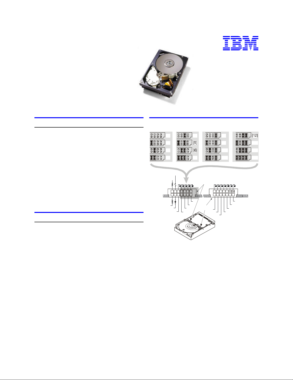
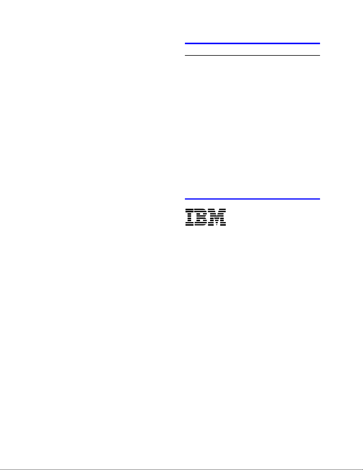
7. Assign a SCSI address to the drive by installing a
jumper on one or more ID bits—D,E,F,G—as
shown on jumper block J-4 in the following
illustrations.
8. Select the desired options by installing the appropriate jumpers. Refer to items A–N in the following
table.
Address jumper and drive option blocks
[0]
[1]
[2]
[3]
+5 V dc
1
+5 V dc
R1
3
5
6
R2
A
B
C
[X] = Address number
Address 6—
Shipping Default
Address 7—
Normally reserved for the host adapter
R1. Resistor value—150 Ohm
R2. Resistor value—150 Ohm for 68-pin
model;
80-pin model—Not Used (0 Ohm)
A. LED: Connect to LED cathode—
(68-pin model); Connected to LED
out pin 77—(80-pin model)
B. Termination power—used only on
for 68-pin model
[4]
[7]
7 9
13
111
1210
14
842
G
F
E
D
J4
J6
C. Force Single-ended Mode
D. ID Bit 0 E. ID Bit 1
F. ID Bit 2 G. ID Bit 3
H. Enable auto spin—68-pin model;
Disable auto spin—80-pin model
I. Auto start delay
J. Delay start 6/12
K. Disable Parity
L. Target Initiated sync negotiation
M. Disable unit attention
N. Reserved
[8]
[9]
[10]
[11]
5 7 9
1 3
4
6 14
2
H
K
I
J
[13]
[14]
[15]
12108
N
M
L
IBM Technology Group Support Center version 1.0
Page 1
Page 2
IBM storage products
SPECIAL NOTES:
Ÿ For this drive to operate in LVD mode all SCSI de-
vices including the SCSI bus host adapter must be
LVD devices.
Ÿ The drive is designed to detect if the SCSI bus is
LVD or SE. The drive will function based upon the
mode that it detects. If for some reason the drive
cannot detect an SE mode bus, place a jumper on
pins 5 and 6 of jumper block J-4 to force SE mode.
Ÿ On 68 pin drives termination power must be pro-
vided. In most cases it is provided by the host
adapter. If it is not provided by the host adapter,
install a jumper on pins 3 and 4 of jumper block J-4
to enable termination power. See the illustration
above. (The 80 pin drive does not provide termination power.)
9. For a 68 pin drive attach the power cable and
ensure that one end of the SCSI cable is connected
to the host adapter. Attach a terminator to the end
of the SCSI cable furthest from the host adapter. If
the drive is the only device on the SCSI cable,
attach it to the cable connector closest to the terminator. Additional drives may be attached to any
unused connector. (The 80 pin drive is plugged
into server backplanes and requires no cables.)
10. Using the appropriate brackets or rails, mount the
drive with any of its six surfaces facing down. Retrieve any loose screws or parts from within the
computer.
11. Ensure the proper routing of cable(s).
12. Plug in your computer. Do not turn it on.
13. Insert the operating system (OS) setup diskette into
the floppy drive.
14. Turn on your computer.
Ÿ If the system boots up, turn off your computer
and replace the cover.
Ÿ If your system does not boot up, turn off your
computer and check all connections and settings. Turn on and boot the system.
Ÿ If the system still fails to boot up, turn off your
computer and remove the new drive to return
the system to its original configuration. Contact
the IBM Hard Disk Drive Technical Support
Center.
Partitioning and formatting (using DOS 5.0 or later)
CAUTION: Partitioning and formatting will destroy any
previous data. When partitioning and formatting a drive
in a system with more than one drive be sure that you
select the correct hard drive.
1. With the OS setup diskette inserted in the floppy
drive, turn on the computer.
2. At the DOS prompt type FDISK, press ENTER, and
follow the instructions on the screen.
3. To format the primary system drive, type FORMAT
C:/S at the DOS command prompt and press
ENTER. The /S parameter makes C: the operating
system startup drive.
4. To format a second drive (not C:), type FORMAT X:
(where X is the drive letter assigned by FDISK) at
the DOS prompt and press ENTER.
5. Remove the diskette and restart your computer. The
partitioning and formatting is complete.
6. Install the operating system.
®
© International Business Machines Corporation 2000
www.ibm.com/harddrive
IBM Technology Group Support Center
Telephone: 888.426.5214 or 507.286.5825
E-mail: drive@us.ibm.com
Singapore Technology Group Support Center
Telephone: 1800.418.9595 or 65.6.418.9595
E-mail: drive@sg.ibm.com
UK Technology Group Support Center
Telephone: 44.1475.898.125
E-mail: drive@uk.ibm.com
Germany Technology Group Support Center
Telephone: 49.7032.153050
E-mail: drive@de.ibm.com
IBM Systems Storage Division
5600 Cottle Road
San Jose CA 95193
www.ibm.com/storage
Printed in the United States of America
03-2000
All Rights Reserved
IBM is the registered trademark and Ultrastar is the trademark of International Business
Machines Corporation.
Other company, product, and service names may be trademarks or service marks of others.
Produced by the IBM Technology Group Support Center.
Hard Disk Drive Specifications for Ultrastar 36LP (Revision 1.0)
Product Description data represents IBM’s design objectives and is provided for comparative
purposes; actual results may vary based on a variety of factors. This product data does not
constitute a warranty. Questions regarding IBM’s warranty terms or methodology used to
derive this data should be referred to the IBM Technology Group Support Center. Data
subject to change without notice.
Date: 10 March 2000
IBM Technology Group Support Center version 1.0
Page 2
 Loading...