

Page 1
IBM storage products
Quick installation guide
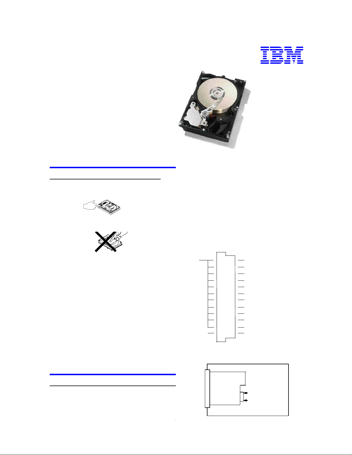
Ultrastar 9ES
SCSI
Models: DDRS-34560
DDRS-39130
Handling precautions
1. Do not cover the breather hole! Covering the
breather hole may result in loss of data.
1. Each drive on the SCSI bus must have a unique
address. Fifty pin (narrow SCSI) devices have 8 possible addresses (0-7) with address 7 (highest priority)
normally reserved for the controller. Sixty-eight and
eighty pin (wide SCSI) devices have 16 possible
addresses (0-15).
2. SCSI address bits 3 (68 & 80 pin only), 2, 1, and 0
Setting the address
2. Do not press on the drive! Do not apply any force
to the drive during handling or installation.
3. Always handle the drive with care to prevent
damage from shock, vibration, or electrostatic discharge (ESD).
4. Do not open the static-protective bag containing the
drive until required. Static electricity can damage the
drive.
5. Turn off and unplug your computer. Remove cover.
6. When installing the drive, touch a grounded,
unpainted metal surface with the static-protective
package containing the drive for at least two seconds.
(This drains static electricity from the package and
from your body.)
7. Handle the drive carefully by the edges. Do not
touch any exposed printed circuit board.
of the 12-pin Option Jumper Block are used to select
the SCSI device ID. The shipping default is ID 6 (bits
2 and 1).
Note: SCSI address bit 3 is reserved on the 50-pin models
Ground
23 (1) 24
21 (2) 22
19 (3) 20
17 (4) 18
15 (5) 16
13 (6) 14
11 (7) 12
9 (8) 10
7 (9) 8
5 (10) 6
3 (11) 4
1 (12) 2
Bit 3
Bit 2
Bit 1
Bit 0
Enable Auto Spin Up
Enable SCSI Terminator (50,68 pin)
Disable Unit Attention
Enable TI-SDTR (50-pin)
Enable TI-SDTR/WDTR (68, 80 pin)
Enable Auto Start Delay
Delay Start 6/12
Disable SCSI Parity Check
LED CathodLED Anode
8. Save the drive packaging material including the
ESD bag in the event that the drive must be returned.
Place the drive in an anti-static bag before placing it in
the shipping container. The warranty will be void if
the drive is not returned in IBM approved packaging.
Power
Connector
Logic Card
Back side of drive
Installation procedure
SCSI I/F
It is advisable to backup all data before proceeding
with the installation.
Connector
JP1
Option blcok
JP12
This procedure may require use of a bootable System
Diskette containing FDISK.COM and FORMAT.COM.
IBM Hard Disk Drive Technical Support Center version 3.0
Page 1
Page 2

IBM storage products
Note: In the table below, “off” means a jumper is not
in place and “on” means a jumper is in place.
AddressBit 0Bit 1Bit 2Bit 3
0offoffoffoff
1onoffoffoff
2offonoffoff
3ononoffoff
4offoffonoff
5onoffonoff
6*offononoff
7onononoff
8offoffoffon
9onoffoffon
10offonoffon
11ononoffon
12offoffonon
13onoffonon
14offononon
15onononon
* Shipping Default
Attaching the drive
1. Turn off the computer, unplug the power cord, and
open the case.
2. The DDRS drive requires Active Termination on
both ends of the SCSI cable (the SCSI controller
normally provides internal termination for one end of
the cable). If the DDRS drive is the only device on the
SCSI cable, attach it to the end of the 68 pin cable
furthest from the controller and enable termination by
placing a jumper on position 6 of the Option Jumper
Block. If the drive is attached to a cable that contains
other devices and the new drive is not attached to the
end of the cable, jumper position 6 must be open and
Active Termination must be supplied by the device at
the end of the cable.
3. Select the other option jumpers as required by your
computer.
4. Attach the power connector.
Mounting the drive
1. Mount the drive securely, using the appropriate
brackets or rails, in any axes, using four 6-32 UNC
metric screws in the bottom or side mounting holes.
2. The maximum screw insertion depth for bottom
mounting is 6.0 mm (.23 in) and for side mounting is
3.5 mm (.14 in).
Configuring your computer
1. Plug in the power cord and power on your computer. Consult your SCSI adapter users guide for
information on configuring a new hard disk drive.
2. Follow the Operating System instructions to format
and partition your drive.
If your system will not boot up after complete
installation, recheck all settings. If the system still
fails to boot up, remove the new drive to return the
system to its original configuration and call the IBM
Hard Disk Drive Technical Support Center.
®
© International Business Machines Corporation 1999
www.ibm.com/harddrive
IBM Hard Disk Drive Technical Support Center
Dept. D8M
3605 Highway 52 North
Rochester, MN 55901
Telephone: 888.IBM.5214 or 507.253.4110
Fax: 507.253.DRIVE
E-mail: drive@us.ibm.com
Singapore Technical Support Center
Telephone: 65.840.9292
E-mail: drive@sg.ibm.com
IBM Systems Storage Division
5600 Cottle Road
San Jose, CA 95193
www.ibm.com/storage
Asia-Pacific Headquarters: 65.320.1234
European Headquarters: 44.01.705.561.871
Japan Sales Branch Office: 81.46645.1039
Printed in the United States of America
01-99
All Rights Reserved
IBM is the registered trademark of International Business Machines Corporation.
Other company, product, and service names may be trademarks or service marks of others.
Produced by the IBM Hard Disk Drive Technical Support Center.
OEM Hard Disk Drive Specifications for DDRS-39130 / DDRS-34560 (Revision 2.0)
Product Description data represents IBM’s design objectives and is provided for com-
parative purposes; actual results may vary based on a variety of factors. This product data
does not constitute a warranty. Questions regarding IBM’s warranty terms or methodology used to derive this data should be referred to the IBM Hard Disk Drive Technical
Support Center. Data subject to change without notice.
Date: 6 January 1999
IBM Hard Disk Drive Technical Support Center version 3.0
Page 2
 Loading...