

Page 1

IBM System Storage DCS3860 Storage System
Installation, User's, and Maintenance
Guide
SC27-5942-00
Page 2

Note
Before using this information and the product it supports, be sure to read the general information in the “Safety” on page
ix and “Notices” on page 161 sections.
This edition applies to the IBM System Storage DCS3860 Storage System with controller firmware version 7.86, and
to all subsequent releases and modifications until otherwise indicated in new editions.
This is the first edition.
Printed in the U.S.A.
© Copyright IBM Corporation 2013.
US Government Users Restricted Rights – Use, duplication or disclosure restricted by GSA ADP Schedule Contract
with IBM Corp.
Page 3

Contents
Figures ...............v
Tables ...............vii
Safety ...............ix
About this document ........xv
Who should read this document .......xv
How this document is organized .......xv
Getting information, help, and service .....xvi
Before you call ............xvi
Using the documentation ........xvi
Finding Storage Manager software, controller
firmware, and README files .......xvi
IBM System Storage Productivity Center . . . xvii
Essential websites for DCS3860 support
information .............xvii
Software service and support .......xvii
Hardware service and support ......xviii
Fire suppression systems ........xviii
Chapter 1. Introduction ........1
Overview ...............1
SAS defined ..............1
Operating system support .........2
DCS3860 Features.............2
Inventory checklist ............3
Receiving product updates and support
notifications .............5
Best practices guidelines .........5
DCS3860 components ...........6
Drive drawers .............7
Disk Drive Modules (DDMs) ........8
Controllers ..............9
Environmental Service Modules (ESMs) ....12
Power supplies ............13
Fan assemblies ............14
Software and hardware compatibility and upgrades 15
Software and firmware support code upgrades 15
Determining firmware versions.......16
Specifications ..............17
Area requirements ...........17
Environmental requirements and specifications 18
Electrical requirements .........21
Heat output, airflow, and cooling ......22
Chapter 2. Installing the DCS3860 . . . 25
Installation overview ...........25
Installation sequence ...........25
Handling static-sensitive devices .......26
Preparing for installation ..........26
Unpacking the shipping box........27
Tools and hardware required .......29
Preparing the site ...........29
Preparing the rack ...........30
Installing the support rails .........30
Installing and removing the handles ......35
Installing the handles ..........35
Removing the handles..........35
Installing the DCS3860 into the rack cabinet using a
lift tool ................35
Installing the DCS3860 into the rack cabinet without
using a lift tool .............38
Installing the DDMs ...........39
Chapter 3. Cabling the DCS3860
storage system ...........43
Controller connectors (with SAS host interface card) 43
Enclosure ID Settings ...........44
Working with SAS cables ..........44
Cabling the EXP3800 expansion enclosure ....46
ESM connectors ............46
Connecting the EXP3800 expansion enclosure . . 46
Adding a storage enclosure to a running
dual-controller configuration .......47
Redundant drive channel pair .......48
Connecting secondary management interface
cables ...............49
Configuring the storage system.......49
Cabling the power supply .........52
Relocating the DCS3860 ..........52
Chapter 4. Operating the DCS3860
storage system and EXP3800
expansion enclosure.........55
Performing the DCS3860 Health Check process . . 55
Hardware inspection ...........56
Powering on the DCS3860 .........56
Installing the IBM DS Storage Manager .....58
Monitoring status through software ......59
Firmware updates ...........60
Troubleshooting the storage system .....60
Checking the LEDs ............61
Front LEDs .............61
Controller LEDs ............62
ESM LEDs..............63
Fan assembly LEDs...........64
AC power-supply LEDs .........65
Drive drawer LEDs ...........65
Disk drive LEDs............66
Seven-segment numeric display LEDs ....68
Cache memory and cache battery .......68
Cache memory ............69
Controller cache battery .........69
Cache battery learn cycle .........69
Turning off the storage system ........70
Performing an emergency shutdown ......72
Restoring power after an unexpected shutdown . . 73
Recovering from an overheated power supply. . . 74
© Copyright IBM Corp. 2013 iii
Page 4

Chapter 5. Replacing components . . . 77
Replacing components...........77
Service Action Allowed LED.........77
Working with controllers ..........77
Removing a controller ...........78
Removing and installing a cover .......79
Replacing a controller ...........80
Removing and disposing of the system-board
lithium battery .............84
Replacing a host interface adapter .......85
Working with hot-swap DDMs ........88
Installing hot-swap hard disk drives .....92
Replacing hot-swap hard disk drives .....92
Replacing multiple DDMs ........94
Replacing an ac power supply ........98
Replacing a memory cache battery ......103
Replacing the memory cache DIMM ......106
Replacing the bezel ...........106
Working with environmental service modules . . 107
Replacing an ESM............107
Replacing a fan assembly .........108
Replacing a drive drawer .........109
Replacing an enclosure chassis........115
Chapter 6. Hardware maintenance . . 123
General checkout ............123
Solving problems ............123
Troubleshooting problems in the DCS3860
storage system ............124
Parts listing ..............132
Seven-segment display sequence codes and their
causes ................134
Determining basic information of drive FRUs . . 138
Chapter 7. Records .........141
Identification numbers ..........141
Storage system and controller information record 142
Sample information record ........142
Installed device records ..........143
Chapter 8. Rack mounting template 145
Chapter 9. Specifications for non-IBM
rack installation ..........149
General safety requirements for IBM products
installed in a non-IBM rack or cabinet .....149
Rack specifications ...........151
Chapter 10. Power cords ......157
Notices ..............161
Trademarks ..............162
Important notes ............163
Particulate contamination .........163
Documentation format ..........164
Noise ................164
Electronic emission notices .........165
Federal Communications Commission Statement 165
Industry Canada Compliance Statement . . . 165
Australia and New Zealand Class A Statement 165
European Union Electromagnetic Compatibility
Directive ..............165
Germany Electromagnetic Compatibility
Directive ..............166
People's Republic of China Class A Statement 167
Taiwan Class A Statement ........167
Taiwan Contact Information .......167
Japan Voluntary Control Council for Interference
Class A Statement ...........168
Japan Electronics and Information Technology
Industries Association Statement ......168
Russia Electromagnetic Interference Class A
Statement .............168
Glossary .............169
Index ...............181
iv
IBM System Storage DCS3860 Storage System: Installation, User's, and Maintenance Guide
Page 5

Figures
1. Isometric view of the DCS3860 ......6
2. DCS3860 hot-swap drive drawers .....7
3. DCS3860 drive drawer .........8
4. Location of the DCS3860 controllers .....9
5. Cache battery and memory cache DIMM
locations .............11
6. ESM SAS port locations........12
7. Location of seven-segment numeric display on
ESM...............13
8. Power supply components .......14
9. Fan assembly components .......15
10. Storage expansion enclosure airflow ....15
11. DCS3860 airflow ...........20
12. Example of cold aisle/hot aisle rack
configuration ............23
13. Front rack mounting template ......31
14. Rear rack mounting template ......32
15. DCS3860 drive drawer with labeled disk
drives ..............40
16. DCS3860 storage system ........43
17. Mini-SAS cable ...........44
18. Connecting a mini-SAS cable.......45
19. Removing a mini-SAS cable .......45
20. ESM connectors ...........46
21. Connecting the first EXP3800 expansion
enclosure .............47
22. Adding enclosures ..........48
23. Host-agent (in-band) management .....50
24. Direct (out-of-band) management method 51
25. Power-supply switches and connectors for
DCS3860 dc models..........57
26. DCS3860 front LEDs and controls .....61
27. DCS3860 storage system and EXP3800 storage
enclosure front LEDs .........61
28. Controller LEDs ...........62
29. SAS host port adapter LEDs .......63
30. ESM LEDs .............64
31. Fan assembly LEDs ..........64
32. AC power-supply LEDs ........65
33. Drive drawer LEDs ..........66
34. Disk drive LEDs ...........67
35. Numeric display LEDs .........68
36. Removing a controller .........79
37. Removing the cover ..........80
38. Removing and replacing a controller ....82
39. Removing the battery unit from the controller 83
40. Location of the Lithium battery ......85
41. Four screws on the cover plate ......86
42. Removing the HIC connector ......87
43. Aligning the HIC connector .......88
44. Opening the drive drawer .......90
45. Inserting a hard disk drive into the connector 91
46. Raising the drive handle ........91
47. Aligning the drive ..........91
48. Locking the drive in place .......92
49. Replacing a power supply .......102
50. Removing a controller ........104
51. Removing a battery unit from the controller 105
52. Memory cache DIMM location ......106
53. Removing the bezel .........107
54. Removing an environmental service module 108
55. Removing a fan assembly .......109
56. Rear view of the storage expansion enclosure
with the right fan assembly removed....111
57. Vertical mounting bracket that connects to the
midplane .............112
58. Horizontal mounting bracket that connects to
the drive drawer ..........112
59. Drive drawer release lever on the side of the
drive drawer ............113
60. Lock-out tumbler located above the drawer
guide ..............114
61. Removing a fan assembly .......116
62. Rear view of the storage expansion enclosure
with the right fan assembly removed....117
63. Vertical mounting bracket that connects to the
midplane .............118
64. Horizontal mounting bracket that connects to
the drive drawer ..........118
65. Drive drawer release lever on the side of the
drive drawer ............119
66. Lock-out tumbler located above the drawer
guide ..............119
67. DCS3860 storage system enclosure parts list 133
68. Seven-segment alphanumeric characters 134
69. An IBM hologram label example .....139
70. Front rack mounting template ......146
71. Rear rack mounting template ......147
72. Top View of non-IBM Rack Specifications
Dimensions ............152
73. Rack specifications dimensions, top front
view ..............153
74. Rack specifications dimensions, bottom front
view ..............153
© Copyright IBM Corp. 2013 v
Page 6

vi IBM System Storage DCS3860 Storage System: Installation, User's, and Maintenance Guide
Page 7

Tables
1. DCS3860 features ...........2
2. Minimum DCS3860 software and firmware
versions..............16
3. DCS3860 storage expansion enclosure
dimensions (with disk drives) ......17
4. DCS3860 weights ..........18
5. DCS3860 component weights ......18
6. DCS3860 shipping carton dimensions when
shipped with drives..........18
7. DCS3860 shipping carton dimensions when
shipped without drives ........18
8. Temperature and humidity requirements for
storage expansion enclosure when in storage
or in transit ............19
9. DCS3860 altitude ranges ........19
10. DCS3860 power and heat dissipation ....20
11. Random vibration power spectral density 20
12. DCS3860 sound levels .........21
13. DCS3860 AC power requirements .....21
14. Legend to the DCS3860 storage system
diagram..............43
15. Fan assembly LEDs ..........65
16. Drive drawer LEDs ..........66
17. Disk drive LEDs ...........67
18. Drive state indicated by the LEDs .....67
19. Drive LED activity ..........89
20. Troubleshooting...........124
21. Parts listing (DCS3860 storage system and
EXP3800 expansion enclosure) ......133
22. Seven-segment display sequence code
definitions ............135
23. Repeating sequences on the seven-segment
display and corresponding errors .....136
24. Controller numeric display diagnostic codes 137
25. ESM numeric display diagnostic codes 138
26. Hard disk drive record ........141
27. Storage system and controller information
record ..............142
28. Sample information record .......143
29. IBM power cords ..........157
30. Limits for particulates and gases .....164
© Copyright IBM Corp. 2013 vii
Page 8

viii IBM System Storage DCS3860 Storage System: Installation, User's, and Maintenance Guide
Page 9

Safety
The caution and danger statements that this document contains can be referenced
in the multilingual IBM®Safety Information document that is provided with your
IBM System Storage
danger statement is numbered for easy reference to the corresponding statements
in the translated document.
v Danger: These statements indicate situations that can be potentially lethal or
extremely hazardous to you. A danger statement is placed just before the
description of a potentially lethal or extremely hazardous procedure, step, or
situation.
v Caution: These statements indicate situations that can be potentially hazardous
to you. A caution statement is placed just before the description of a potentially
hazardous procedure step or situation.
v Attention: These notices indicate possible damage to programs, devices, or data.
An attention notice is placed just before the instruction or situation in which
damage could occur.
Before installing this product, read the following danger and caution notices.
®
DCS3860 storage expansion enclosure. Each caution and
Statement 1
© Copyright IBM Corp. 2013 ix
Page 10
DANGER
Electrical current from power, telephone, and communication cables is
hazardous.
To avoid a shock hazard:
v Do not connect or disconnect any cables or perform installation,
maintenance, or reconfiguration of this product during an electrical storm.
v Connect all power cords to a properly wired and grounded electrical outlet.
v Connect to properly wired outlets any equipment that will be attached to
this product.
v When possible, use one hand only to connect or disconnect signal cables.
v Never turn on any equipment when there is evidence of fire, water, or
structural damage.
v Disconnect the attached power cords, telecommunications systems,
networks, and modems before you open the device covers, unless
instructed otherwise in the installation and configuration procedures.
v Connect and disconnect cables as described in the following table when
installing, moving, or opening covers on this product or attached devices.
To Connect: To Disconnect:
1. Turn everything OFF.
2. First, attach all cables to devices.
3. Attach signal cables to connectors.
4. Attach power cords to outlet.
5. Turn device ON.
1. Turn everything OFF.
2. First, remove power cords from outlet.
3. Remove signal cables from connectors.
4. Remove all cables from devices.
Statement 2
CAUTION:
When replacing the lithium battery, use only an equivalent type battery
recommended by the manufacturer. If your system has a module containing a
lithium battery, replace it only with the same module type made by the same
manufacturer. The battery contains lithium and can explode if not properly used,
handled, or disposed of.
Do not:
v Throw or immerse into water
v Heat to more than 100° C (212° F)
v Repair or disassemble
Dispose of the battery as required by local ordinances or regulations.
x IBM System Storage DCS3860 Storage System: Installation, User's, and Maintenance Guide
Page 11

Statement 3
CAUTION:
When laser products (such as CD-ROMs, DVD drives, fibre optic devices, or
transmitters) are installed, do not:
v Remove the covers of the laser product as it might expose the product to
hazardous laser radiation. There are no serviceable parts inside the device.
v Perform procedures, or use controls or adjustments, other than those specified
in this guide, as it might cause radiation exposure.
DANGER
Some laser products contain an embedded Class 3A or Class 3B laser diode.
When laser radiation is open, do not stare into the beam or view with optical
instruments.
Class 1 Laser statement
Class 1 Laser Product
Laser Klasse 1
Laser Klass 1
Luokan 1 Laserlaite
Apparell Laser de Calsse 1À
IEC 825-11993 CENELEC EN 60 825
Statement 4
≥ 18 kg (39.7 lb) ≥ 32 kg (70.5 lb) ≥ 55 kg (121.2 lb)
CAUTION:
Use safe practices when lifting.
Safety xi
Page 12
Statement 5
CAUTION:
The power control button on the device and the power switch on the power
supply do not turn off the electrical current supplied to the device. The device
also might have more than one power cord. To remove all electrical current from
the device, ensure that all power cords are disconnected from the power source.
2
1
Statement 8
CAUTION:
Never remove the cover on a power supply or any part that has the following
label attached.
Hazardous voltage, current, and energy levels are present inside any component
that has this label attached. There are no serviceable parts inside these
components. If you suspect a problem with one of these parts, contact a service
technician.
Statement 29
xii IBM System Storage DCS3860 Storage System: Installation, User's, and Maintenance Guide
Page 13
CAUTION:
This equipment is designed to permit the connection of the earthed conductor of
the dc supply circuit to the earthing conductor at the equipment.
This equipment is designed to permit the connection of the earthed conductor of
the dc supply circuit to the earthing conductor at the equipment. If this
connection is made, all of the following conditions must be met:
v This equipment shall be connected directly to the dc supply system earthing
electrode conductor or to a bonding jumper from an earthing terminal bar or
bus to which the dc supply system earthing electrode conductor is connected.
v This equipment shall be located in the same immediate area (such as, adjacent
cabinets) as any other equipment that has a connection between the earthed
conductor of the same dc supply circuit and the earthing conductor, and also
the point of earthing of the dc system. The dc system shall not be earthed
elsewhere.
v The dc supply source shall be located within the same premises as this
equipment.
v Switching or disconnecting devices shall not be in the earthed circuit
conductor between the dc source and the point of connection of the earthing
electrode conductor.
Statement 30
CAUTION:
To reduce the risk of electric shock or energy hazards:
v This equipment must be installed by trained service personnel in a
restricted-access location, as defined by the NEC and IEC 60950-1, First
Edition, The Standard for Safety of Information Technology Equipment.
v Connect the equipment to a reliably grounded safety extra low voltage (SELV)
source. An SELV source is a secondary circuit that is designed so that normal
and single fault conditions do not cause the voltages to exceed a safe level (60
V direct current).
v The branch circuit overcurrent protection must be rated 20 A.
v Use 12 American Wire Gauge (AWG) or 2.5 mm2 copper conductor only, not
exceeding 4.5 meters in length.
v Incorporate a readily available approved and rated disconnect device in the
field wiring.
CAUTION:
This unit has more than one power source. To remove all power from the unit,
all dc MAINS must be disconnected.
Safety xiii
Page 14

Cable Warning
WARNING: Handling the cord on this product or cords associated with
accessories sold with this product, will expose you to lead, a chemical known to
the State of California to cause cancer, and birth defects or other reproductive
harm. Wash hands after handling.
xiv IBM System Storage DCS3860 Storage System: Installation, User's, and Maintenance Guide
Page 15

About this document
This document provides instructions for installing and customizing the IBM
System Storage DCS3860 storage system and the EXP3800 expansion enclosure. It
also provides maintenance procedures and troubleshooting information.
Who should read this document
This document is intended for system operators and service technicians who have
extensive knowledge of Fibre Channel Serial Attached SCSI (SAS) and network
technology.
How this document is organized
Chapter 1, “Introduction,” on page 1 describes the IBM System Storage DCS3860
storage system and the EXP3800 expansion enclosure. This chapter includes an
inventory checklist and an overview of the storage expansion enclosure features,
operating specifications, and components.
Chapter 2, “Installing the DCS3860,” on page 25 contains information on how to
install the DCS3860.
Chapter 3, “Cabling the DCS3860 storage system,” on page 43 contains information
on how to cable the DCS3860.
Chapter 4, “Operating the DCS3860 storage system and EXP3800 expansion
enclosure,” on page 55 contains information on how to power on and off the
storage expansion enclosure, recover from an overheated power supply,
troubleshoot the storage expansion enclosure, and interpret LEDs.
Chapter 5, “Replacing components,” on page 77 contains step-by-step instructions
about how to install or remove customer replaceable units (CRUs), such as hard
disk drives, power supplies, fan assemblies, environmental service modules
(ESMs), drive drawers, and SFP modules.
Chapter 6, “Hardware maintenance,” on page 123 describes problems and
symptoms that are specific to your storage expansion enclosure. It also provides a
parts list for the DCS3860.
Chapter 7, “Records,” on page 141 provides a table that you can use to record and
update important information about your DCS3860, including serial number and
device records. Whenever you add options to your DCS3860, be sure to update the
information in this table.
Chapter 8, “Rack mounting template,” on page 145 provides the rack mounting
templates for installation of the DCS3860. If you want to tear out the templates
from the document for use during installation, use these copies of the templates.
Chapter 9, “Specifications for non-IBM rack installation,” on page 149 provides
safety requirements and rack specifications for installing DCS3860 storage systems
and DCS3860 storage expansion enclosures into non-IBM racks.
© Copyright IBM Corp. 2013 xv
Page 16

Chapter 10, “Power cords,” on page 157 lists power cord information for the
DCS3860.
Getting information, help, and service
If you need help, service, or technical assistance or just want more information
about IBM products, you will find a wide variety of sources available from IBM to
assist you. This section contains information about where to go for additional
information about IBM and IBM products, what to do if you experience a problem
with your system, and whom to call for service, if it is necessary.
Before you call
Before you call, take these steps to try to solve the problem yourself:
v Check all cables to make sure that they are connected.
v Check the power switches to make sure that the system is turned on.
v Use the troubleshooting information in your system documentation, and use the
diagnostic tools that come with your system.
v Check for technical information, hints, tips, and new device drivers at the IBM
System Storage Disk Support Web site pages that are listed in this section.
v Use an IBM discussion forum on the IBM Web site to ask questions.
You can solve many problems without outside assistance by following the
troubleshooting procedures that IBM provides in the DS Storage Manager online
help or in the documents that are provided with your system and software. The
information that comes with your system also describes the diagnostic tests that
you can perform. Most systems, operating systems, and programs come with
information that contains troubleshooting procedures and explanations of error
messages and error codes. If you suspect a software problem, see the information
for the operating system or program.
Using the documentation
Information about your IBM system and preinstalled software, if any, is available
in the documents that come with your system; this includes printed books, online
documents, README files, and help files. See the troubleshooting information in
your system documentation for instructions for using the diagnostic programs. The
troubleshooting information or the diagnostic programs might tell you that you
need additional or updated device drivers or other software.
Finding Storage Manager software, controller firmware, and README files
IBM DS Storage Manager software and controller firmware versions are available
on the product DVD and can also be downloaded from the web.
Important: Before you install IBM DS Storage Manager software, consult the
README file. Updated README files contain the latest device driver versions,
firmware levels, limitations, and other information not found in this document.
Storage Manager README files are available on the web, at the following address:
http://www.ibm.com/support/entry/portal
xvi IBM System Storage DCS3860 Storage System: Installation, User's, and Maintenance Guide
Page 17

To access the documentation related to your storage system, operating system, and
DS Storage Manager version from the IBM support portal, complete the following
steps:
1. Go to http://www.ibm.com/support/entry/portal.
2. Under Choose your products, click Browse for a product or Search for a
product.
3. Under Choose your task, click Documentation.
4. Under See your results, click View your page.
5. In the Product documentation box, click the link for the publication that you
want to access.
IBM System Storage Productivity Center
The IBM System Storage Productivity Center (SSPC) is an integrated hardware and
software solution that provides a single point of entry for managing IBM System
Storage, IBM System Storage SAN Volume Controller clusters, and other
components of your data storage infrastructure. Therefore, you can use the IBM
System Storage Productivity Center to manage multiple IBM System Storage
product configurations from a single management interface.
To learn how to incorporate the DS Storage Manager with the IBM System Storage
Productivity Center, see the IBM System Storage Productivity Center Information
Center at the following website:
publib.boulder.ibm.com/infocenter/tivihelp/v4r1/index.jsp
Essential websites for DCS3860 support information
The most up-to-date information about DCS3860 storage systems and IBM DS
Storage Manager, including documentation and the most recent software, firmware,
and NVSRAM downloads, is available on the IBM support portal. To access these:
1. Go to http://www.ibm.com/support/entry/portal.
2. Under Choose your products, click Browse for a product or Search for a
product.
3. Under Choose your task, click Downloads.
4. Under See your results, click View your page.
5. In the Downloads and fixes, click the link for the download that you want to
access.
Software service and support
Through the IBM Support Line, for a fee you can get telephone assistance with
usage, configuration, and software problems. For information about which
products are supported by Support Line in your country or region, go to the
following website:
www.ibm.com/services/sl/products
For more information about the IBM Support Line and other IBM services, check
the following websites:
v www.ibm.com/services
v www.ibm.com/planetwide
About this document xvii
Page 18

Hardware service and support
You can receive hardware service through IBM Integrated Technology Services or
through your IBM reseller, if your reseller is authorized by IBM to provide
warranty service. Go to the following Web site for support telephone numbers:
www.ibm.com/planetwide
In the U.S. and Canada, hardware service and support is available 24 hours a day,
7 days a week. In the U.K., these services are available Monday through Friday,
from 9 a.m. to 6 p.m.
Fire suppression systems
A fire suppression system is the responsibility of the customer. The customer's own
insurance underwriter, local fire marshal, or a local building inspector, or both,
should be consulted in selecting a fire suppression system that provides the correct
level of coverage and protection. IBM designs and manufactures equipment to
internal and external standards that require certain environments for reliable
operation. Because IBM does not test any equipment for compatibility with fire
suppression systems, IBM does not make compatibility claims of any kind nor
does IBM provide recommendations on fire suppression systems.
xviii IBM System Storage DCS3860 Storage System: Installation, User's, and Maintenance Guide
Page 19

Chapter 1. Introduction
This section describes the operating specifications, features, and components for
the IBM System Storage DCS3860 storage system and EXP3800 expansion unit.
Note: For Ethernet Interfaces: DCS3860 storage system is not intended to be
connected directly or indirectly by any means whatsoever to interfaces of public
telecommunication networks.
This chapter also includes an inventory checklist and important information about
best practices guidelines and product updates for your DCS3860.
Overview
The DCS3860 storage system is designed to meet the storage needs of highly
scalable, data streaming applications in high-performance computing
environments. The DCS3860 is a high-performance system that is designed to meet
midrange storage requirements. This high-availability, modular, and scalable
storage system provides SAN-attached 6 Gbps Serial Attached SCSI (SAS)
connectivity, support for RAID levels 0, 1, 3, 5, 6, and 10, data access and data
protection, and other advanced functions.
Note: RAID 6 uses a P+Q design implementation. When RAID level 1 is
implemented and there are more than two drives, RAID level 10 is automatically
implemented.
SAS defined
The DCS3860 storage system supports attachment of the EXP3800 expansion
enclosure. The DCS3860 supports configurations of SAS and Near-Line SAS disks,
or a mix of these types of disk drives. For details on the maximum number of disk
drives supported, maximum storage capacity, and other features of the storage
system, see “DCS3860 Features” on page 2.
The DCS3860 is a 4U, rack-mountable storage enclosure that supports up to two
redundant, dual-active RAID storage controllers or environmental service modules,
depending on the model. As a standard, the DCS3860 storage system RAID
controllers have two 6 Gbps x4 SAS expansion ports on the base controller. Each
controller has an additional slot in which you can install a Host Interface Card
(HIC). For details on the supported HIC, see “DCS3860 Features” on page 2.
The IBM DS Storage Manager client is also available for the DCS3860 storage
system. This storage management software is designed to help centralize storage
management, simplify partitioning of the DCS3860 series storage into as many as
512 partitions, and strategically allocate storage capacity to maximize storage
space.
The Serial Attached SCSI (SAS) is a point-to-point serial architecture that replaces
the parallel SCSI bus technology but still retains usage of the standard SCSI
command set. The SAS point-to-point architecture provides a dedicated,
full-duplex channel that can transfer data at 6 Gbps in each direction. The Serial
SCSI Protocol (SSP) is used to support SAS-only drives.
© Copyright IBM Corp. 2013 1
Page 20

Nearline SAS or NL-SAS drives are enterprise SATA drives that offer a native SAS
interface. NL-SAS drives support dual I/O ports allowing for redundant data
paths, a faster interface compared to SATA, and the ability to support the SCSI
command set.
Operating system support
For host operating system support, refer to the IBM DCS3860 product at the IBM
System Storage Interoperation Center (SSIC):
www.ibm.com/systems/support/storage/config/ssic/index.jsp
DCS3860 Features
For a list of the operating specifications, such as weight, height, and heat output,
see “Specifications” on page 17.
Table 1. DCS3860 features
General:
v Modular components
– RAID storage controller modules
– Environmental services modules
(ESMs)
– Power supplies
– Fan assembly
– High-capacity disk drives
Storage system:
v RAID controllers:
– Expansion: Two 26 pin, mini-SAS
connector per controller
– Dual 1 Gbps Ethernet management
ports
– Seven segment display
v Power supply:
– 2 hot-swap 1755-watt (200 - 240 V ac)
standard
– Redundant power
v Premium Feature Options:
– Performance Read Cache
Storage expansion
enclosure:
v ESM:
– Host interface: Two
26-pin, mini-SAS
connectors per
controller
– Expansion: One 26
pin, mini-SAS
connector per
controller
– Single 100 Mbps
Ethernet debug
port
– Seven segment
display
v Power supply:
– 2 hot-swap
1755-watt (200 240 V ac) standard
– Redundant power
2 IBM System Storage DCS3860 Storage System: Installation, User's, and Maintenance Guide
Page 21

Table 1. DCS3860 features (continued)
v Technology
– Support for RAID 0, 1, 3, 5, 6, and 10
disk arrays
– Support for up to 360 SAS or NL-SAS
disk drives when using five additional
expansion enclosures
– Controller cache size of 12 GB per
controller for a total of 24 GB per
storage system
– Storage capacity up to 1440 TB
– Each controller supports 1 host
interface adapter. Support for:
- 6 Gbps SAS
– Redundant controllers or ESMs,
power supply, and fan assemblies
– Hot-swap technology for controllers
and power supply
v User interface
– Built-in power, activity, and fault
LEDs, identification labeling on
components, rear LEDs, and
connectors
– Easy-to-replace drives, power
supplies, fan assemblies, controllers,
and ESMs
Inventory checklist
The following illustration and inventory list display the items that you need to
install the storage expansion enclosure in the rack cabinet. If any items are missing
or damaged, contact your place of purchase.
Chapter 1. Introduction 3
Page 22

Note: The illustration might differ slightly from your hardware.
Fan
assembly (2)
PDU jumper cord
Clip nuts (4)
M5 x 8 mm
screws (16)
Handles (4)
Bezel
Rear brackets
Support rails
Power
supply (2)
Storage
enclosure
Controller
or ESM (2)
Drive drawer
assembly (5)
After you unpack the DCS3860, ensure that you have the following items:
v 4U-high storage enclosure (1)
– A box containing Disk Drive Modules (if you have ordered: the box may be
shipped in this carton or separately)
– Drive drawer assemblies (5)
– Fan assemblies (2)
– Power supplies (2)
– ESMs (2) (for 1813 80E)
– Controllers (2) (for 1813 86C)
v Handles (4), packaged in a smaller box inside the shipping box
v Bezel (1)
v Rack-mounting hardware kit (1), packaged in a smaller box inside the shipping
box, including:
– Rails (2), right and left assembly
– Rear brackets (2)
– M5 black hex-head slotted screws (16)
dcsi0057
4 IBM System Storage DCS3860 Storage System: Installation, User's, and Maintenance Guide
Page 23

Note: The screws are either preinstalled in the support rails or packaged in a
plastic bag.
– Washers (8)
– Clip nuts (4)
Important: The DCS3860 does not ship with region-specific ac power cords. You
must obtain the IBM-approved power cords for your region. For more information,
see Chapter 10, “Power cords,” on page 157.
Receiving product updates and support notifications
Download the latest versions of these packages at the time of initial installation
and when product updates become available.
v DS Storage Manager host software
v DCS3860 storage system controller firmware and NVSRAM
v EXP3800 expansion unit ESM firmware
v Drive firmware
Important
Subscribe to support notifications for product updates and update the system with
the latest firmware.
For more information about how to register for support notifications, see the Stay
Informed section of the IBM Disk Support website.
Best practices guidelines
IBM recommends guidelines or best practices for optimal operation of your system.
v Ensure that your system is in an optimal state before you shut it down. Never
turn off the power if any Service Action Required LED is lit. Ensure that you
resolve any error conditions before you shut down the system.
v Back up the data on your storage drives periodically.
v To maintain power redundancy, plug the right and left power supplies of the
DCS3860 storage system into two independent external power circuits through
the distribution units that are inside a rack cabinet or directly into external
receptacles. The DCS3860 storage system and all its attached expansion
enclosures can then have power in the event that only one power circuit is
available. Also, during an unattended restoration of power, the storage devices
in the configuration can power on simultaneously.
Note: Do not overload the circuits that power your storage system and storage
expansion enclosures. Use additional pairs of power distribution units (PDUs) if
necessary. Refer to Table 10 on page 20 for information about storage expansion
enclosure power requirements. Contact your IBM service representative for
additional information.
v Before a planned system shutdown or after system additions, removals, or
modifications (including firmware updates, logical drive creations, storage
partitioning definitions, hardware changes, and so on), complete the following
tasks:
1. Save the storage system profile.
2. Save the storage system configuration.
3. Save the Collect All Support Data (CASD).
Chapter 1. Introduction 5
Page 24

Ensure that you save the files in a location other than in the logical drives,
which were created for the storage system.
For more information about how to complete these tasks, check the IBM DS
Storage Manager online help or the IBM DS Storage Manager guide for your
operating system.
v During any maintenance or attended power on procedure, carefully follow the
power on sequence listed in “Restoring power after an unexpected shutdown”
on page 73. Ensure that each component of the system is powered on in the
correct order, so that the controller can optimally access all the storage systems.
v The storage system supports simultaneous power on to the system components.
However, you must always follow the power on sequence listed in “Restoring
power after an unexpected shutdown” on page 73.
v A storage system in an optimal state should recover automatically from an
unexpected shutdown and an unattended restoration of power to system
components. After power is restored, call IBM support if any of the following
conditions occur:
– The storage system logical drives and systems do not display in the DS
Storage Manager graphical user interface (GUI).
– The storage system logical drives and systems are not online.
– The storage system logical drives and systems are degraded.
DCS3860 components
The DCS3860 storage system directs and manages the I/O activity between a host
and the drives in a RAID array. The EXP3800 expansion unit provides additional
storage capacity to the storage system.
Figure 1 shows the DCS3860 unit without the front bezel in place.
Note: The illustrations in this document might differ slightly from your hardware.
Figure 1. Isometric view of the DCS3860
6 IBM System Storage DCS3860 Storage System: Installation, User's, and Maintenance Guide
dcsi0031
Page 25

The DCS3860 has the following removable components. These components, called
field replaceable units (FRUs), are accessible from the front or back of the
enclosure.
v Five drive drawers, including the right and left cable chains.
v 20 minimum to 60 maximum Disk Drive Modules (DDMs)
v Two RAID controllers (for the 1813-86C)
v Two environmental service modules (ESMs) (for the 1813-80E)
v Two power supplies
v Two fan assemblies
You can use the hot-swap features of the DCS3860 to remove and replace DDMs,
power supplies, fan assemblies, ESMs, and RAID controllers without turning off
the enclosure. You can maintain the availability of your system while a hot-swap
device is removed, installed, or replaced.
The EXP3800 expansion unit is designed for use with the DCS3860 storage system.
The DCS3860 storage system can support up to five EXP3800 expansion enclosures
for a total of 360 disk drive modules (DDM).
Drive drawers
The DCS3860 storage system and EXP3800 expansion enclosure have five
removable drive drawers that are accessible from the front of the enclosure. Each
drive drawer can contain up to 12 disk drives (see Figure 3 on page 8). With the
drive drawers fully populated, the DCS3860 can support up to 60 DDMs. (see
Figure 2).
Note: Drive drawers might be referred to as drive trays in other publications.
1
Drive
drawers
Figure 2. DCS3860 hot-swap drive drawers
2
3
4
!
5
dcsq0004
Chapter 1. Introduction 7
Page 26
Front-row
drives
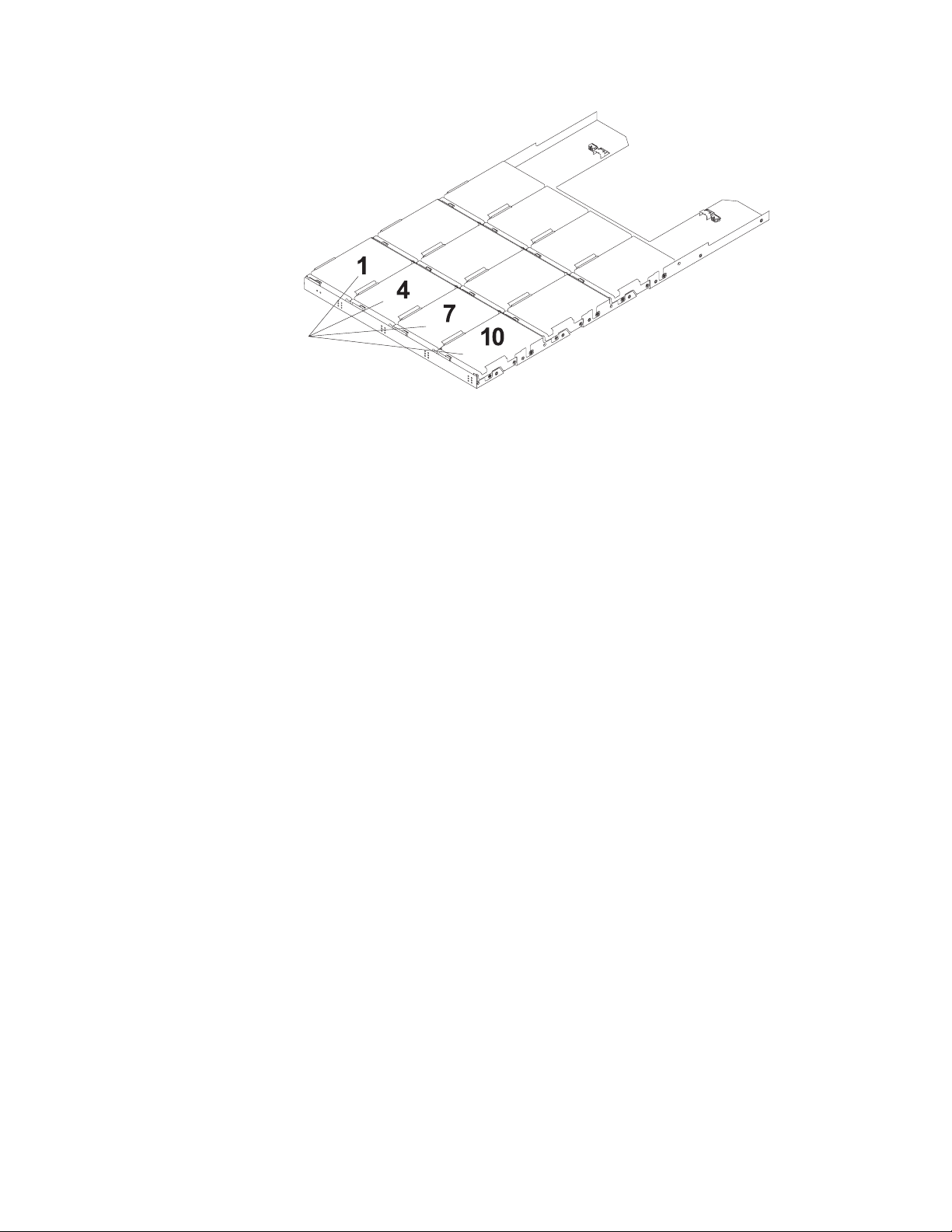
Figure 3. DCS3860 drive drawer
Important: The installation order within each drive drawer is from left to right in
rows. Slots 1, 4, 7, and 10 must have a drive installed in these locations to ensure
that there is sufficient airflow to the drives (see Figure 3). To verify these slots,
consult the overlay on the front of each of the five drive drawers. Ensure that the
four drives in each row are next to each other. The long edge of each drive must
touch the drive next to it. To maintain uniform airflow across all drive drawers, the
storage expansion enclosure must be configured with a minimum of 20 drives,
with four drives in the front row of each of the five drive drawers.
Disk Drive Modules (DDMs)
The DCS3860 supports up to 60 DDMs in five drive drawers that are accessible
from the front of the storage expansion enclosure. The disk drawer system board
supports 6 Gbps SAS (Serial Attached SCSI) and Near-Line SAS interface.
Attention: The DCS3860 and EXP3800 DDMs and the EXP5060 SATA DDMs are
not compatible. Do not use the DCS3860 DDMs in an EXP5060 storage expansion
enclosures. Similarly, do not use the EXP5060 SATA DDMs in a DCS3860 enclosure.
There are no serviceable parts in a DDM FRU. If the DDM FRU fails, it must be
replaced. When replacing a DDM FRU, ensure that you order and install the
correct DDM FRU.
Attention:
1. After you remove a drive FRU, wait 90 seconds before replacing or reseating
the drive FRU to allow the drive to properly spin down. Failure to do so can
cause undesired events.
2. Never hot-swap a drive FRU when its green Activity LED is flashing. Hot-swap
a drive FRU only when its associated blue Service Action Allowed LED is lit
and the drive is inactive.
If the DDM you want to remove is not in a failed or bypass state, always use the
DS Storage Manager client program either to place the DDM in a failed state or to
place the array that is associated with the DDM (or DDMs) in an offline state
before you remove it from the enclosure.
8 IBM System Storage DCS3860 Storage System: Installation, User's, and Maintenance Guide
Page 27
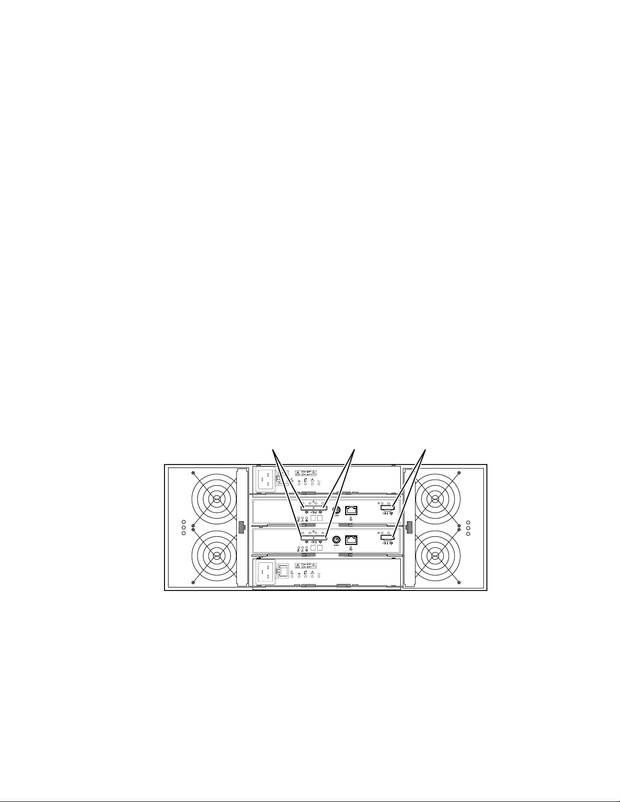
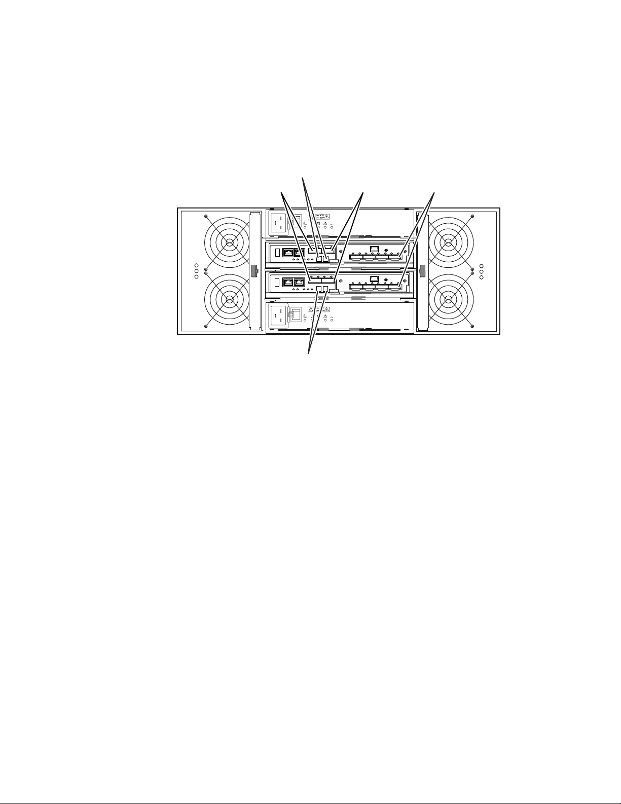
Controllers
The DCS3860 storage system (1813-86C) has two redundant controllers, which can
be hot-swapped. The controllers contain the storage system control logic, interface
ports, and LEDs. The controllers install from the rear of the storage enclosure.
Controller A is installed in storage bridge bay slot A (SBB A) and controller B is
installed in storage bridge bay slot B (SBB B). All connections to the hosts and the
expansion enclosures are made through the controllers. Figure 4 shows the location
of the controllers in the DCS3860.
SBB A
2
1
I
O
ACDC
SBB B
Controller or ESM
Controller or ESM
2
1
I
O
ACDC
dcsi0030
Figure 4. Location of the DCS3860 controllers
Note: To preserve optimal airflow, do not remove a failed controller FRU from the
DCS3860 chassis until you are ready to replace it with a new FRU.
Information about the condition of the controllers is conveyed by indicator LEDs
on the controller. See “Controller LEDs” on page 62 for more information about the
LEDs found on the RAID controller.
Controller cable connections
The SAS ports, Ethernet ports, and the optional HIC on a DCS3860 system are
depicted with a diagram. Each controller contains the following connections:
v Two 6 Gbps x4 SAS expansion ports to connect EXP3800 expansion enclosures
v Two RJ-45 Ethernet ports for system management
v Support for one optional host interface card (HIC)
Attention: The DCS3860 storage system controllers must be identical to each
other in hardware (host port adapter and cache size) and firmware. If you install a
host port adapter in one controller, you must install an identical host port adapter
in the other controller.
Expansion ports
Each controller has two 6 Gbps x4 SAS expansion ports to connect expansion
enclosures to the storage system. The four SAS expansion ports (two on each
controller) are used to form a redundant drive channel.
Ethernet management ports
The Ethernet connections provide for out-of-band management of the controller.
Each controller has two RJ-45 Ethernet ports that support either 100Base-T or
1000Base-T connections.
Chapter 1. Introduction 9
Page 28

One Ethernet port on each controller is used for daily management of the storage
system. The second port is reserved for service personnel or acts as a backup port
if the primary port fails.
1. Connect the management station to the management port of the system.
2. Start IBM DS Storage Manager from your management station. The Enterprise
Management and Confirm Initial Automatic Discovery window opens.
3. Complete one of the following tasks:
v If the DHCP server is set up, select Automatic Discovery from the Enterprise
Management Window to discover the storage system. After the initial
automatic discovery is complete, the Enterprise Management window
displays all hosts and storage system that are attached to the local
subnetwork.
Note: Ensure that the management station is under the same DHCP service.
To discover storage system that are outside of the local subnetwork, click
Edit > Add Storage Subsystem and manually enter the IP address of the
storage system controller management ports or the IP address of a remote
host.
v If the DHCP server is not set up, set the IP addresses of the storage system
controller management ports to the same subnet of default IP addresses for
the controllers.
The default IP address for each controller is as follows:
– Port 1 on controller A is 192.168.128.101
– Port 2 on controller A is 192.168.129.101
– Port 1 on controller B is 192.168.128.102
– Port 2 on controller B is 192.168.129.102
– The subnet mask for both Ethernet ports is 255.255.255.0
4. Click Rename the Storage Subsystem. Use the serial number of the storage
system as the first part of the system name. The host name has a maximum of
30 characters.
5. Click Locate the Storage Subsystem. A blue LED flashes on the front of the
selected storage system. Label the storage system with its associated name.
6. Highlight the storage system and click Tools > Manage Storage Subsystem to
open the Subsystem Management window and the Task Assistant.
7. If the storage system is not in Optimal state, click the Recover from Failure
icon in the Task Assistant. Follow the steps in the Recovery Guru. When the
system is Optimal, close the Task Assistant.
8. In the Subsystem Management window, click Storage Subsystem > View >
Profile. Click the Controller Firmware, NVSRAM, ESM Firmware, Drive
Product ID, and Firmware Versions tabs, and write each number in the
following table for future use.
Controller firmware:
NVSRAM:
ESM firmware:
Drive product ID:
Firmware versions:
9. Save the profile for future use and close the profile window.
10 IBM System Storage DCS3860 Storage System: Installation, User's, and Maintenance Guide
Page 29
Note: Save a copy of the storage system profile and the Collect All Support
Data bundle when you make configuration changes to the storage system.
Serial port
The serial port on each controller uses a 6-pin Mini-DIN connector. This port is
intended to be used by service personnel only to provide diagnostic operations on
the RAID controllers. The maximum baud rate is 115200 bps and the factory
default baud rate is 38400 bps.
Attention: Incorrect use of the serial port can result in loss of data access and, in
some cases, in loss of data. Do not make any connections to the serial port unless
you do so under the direct guidance of IBM support personnel.
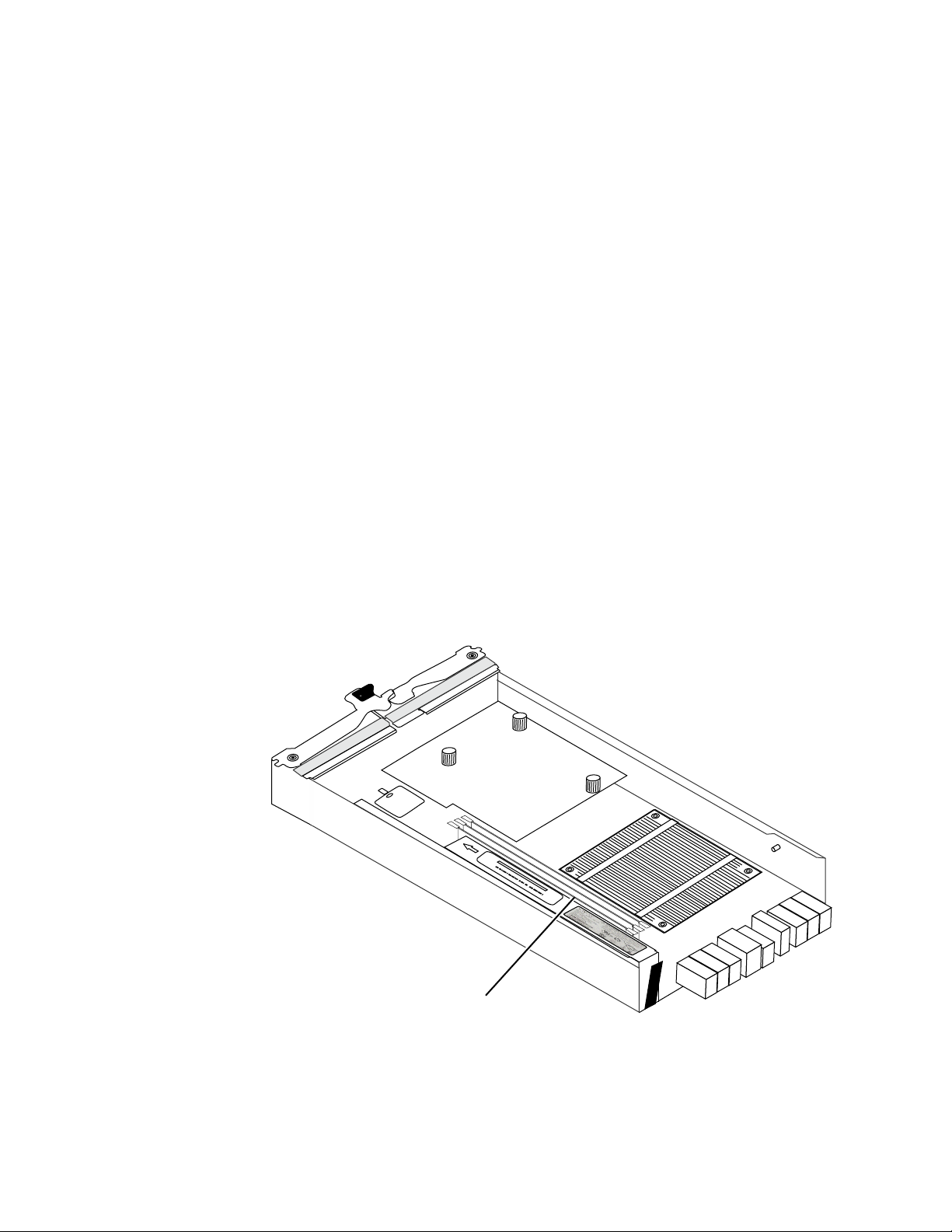
Cache memory
The data cache memory is a buffer used to temporarily store hard disk drive data
during data read and write operations. Each RAID controller has data cache
memory. The Cache Active LED on the controller turns on when the cache contains
data that is not written to the hard disk drives. The Cache Active LED is off when
there is no data stored in cache. The DCS3860 storage system is available with 24
GB (12 GB per controller) of cache memory.
Cache battery backup module
Each controller contains 12 GB cache memory. The controller also contains a sealed,
rechargeable lithium ion battery that maintains data in the cache so that it can be
transferred to flash memory if the power fails.
Figure 5 shows the locations of the cache battery and memory cache DIMM in the
controller.
Memory cache DIMMs (three)
Figure 5. Cache battery and memory cache DIMM locations
dcsi0074
The battery chargers in the power supplies perform a battery-learn test when the
storage system is started for the first time and on a regularly scheduled interval
thereafter. Data caching starts after the battery tests are completed.
Chapter 1. Introduction 11
Page 30
The condition of the battery is indicated by an LED on the rear of the controller
(see “Controller LEDs” on page 62 for the location of the battery fault LED and
conditions that the LED indicates). You can also check the status of the battery
using the IBM DS Storage Manager.
Environmental Service Modules (ESMs)
The ESMs are at the back of the EXP3800 expansion enclosure. The ESM in SBB A
is called ESM A, while the ESM in SBB B is called ESM B. One ESM continues to
operate if the other ESM fails.
Note: To preserve the optimal airflow, do not remove a failed ESM FRU from the
DCS3860 chassis until you are ready to replace it with a new FRU.
The ESMs contain the storage expansion enclosure control logic, interface ports,
and LEDs. Each ESM has two 6 Gbps x4 SAS IN ports and a single 6 Gbps x4 SAS
OUT port. The SAS IN ports are used to connect the ESM to a RAID controller or
another ESM. The SAS OUT port is used to cascade that ESM to another enclosure.
The use of both ports on each ESM results in a redundant drive connection.
Figure 6 shows the location of the SAS IN and OUT ports on the ESMs.
The DCS3860 ESMs support automatic ESM firmware synchronization. With this
function, a new ESM with a different version of ESM firmware can automatically
synchronize with the firmware version of the existing ESM in the enclosure. To
enable automatic ESM firmware synchronization, ensure that:
1. The IBM DS Storage Manager Event Monitor is installed and running.
2. The storage system is defined in the Enterprise Management window of the
IBM DS Storage Manager client (SMclient).
SAS out connectorSAS in connector 2SAS in connector 1
2
1
I
O
I
O
Lnk Lnk Lnk Lnk
1
8 8
Lnk Lnk Lnk Lnk
1
8 8
2
1
ACDC
2
ID/Diag
2
ID/Diag
ACDC
Lnk Lnk
Lnk Lnk
dcsi0002
Figure 6. ESM SAS port locations
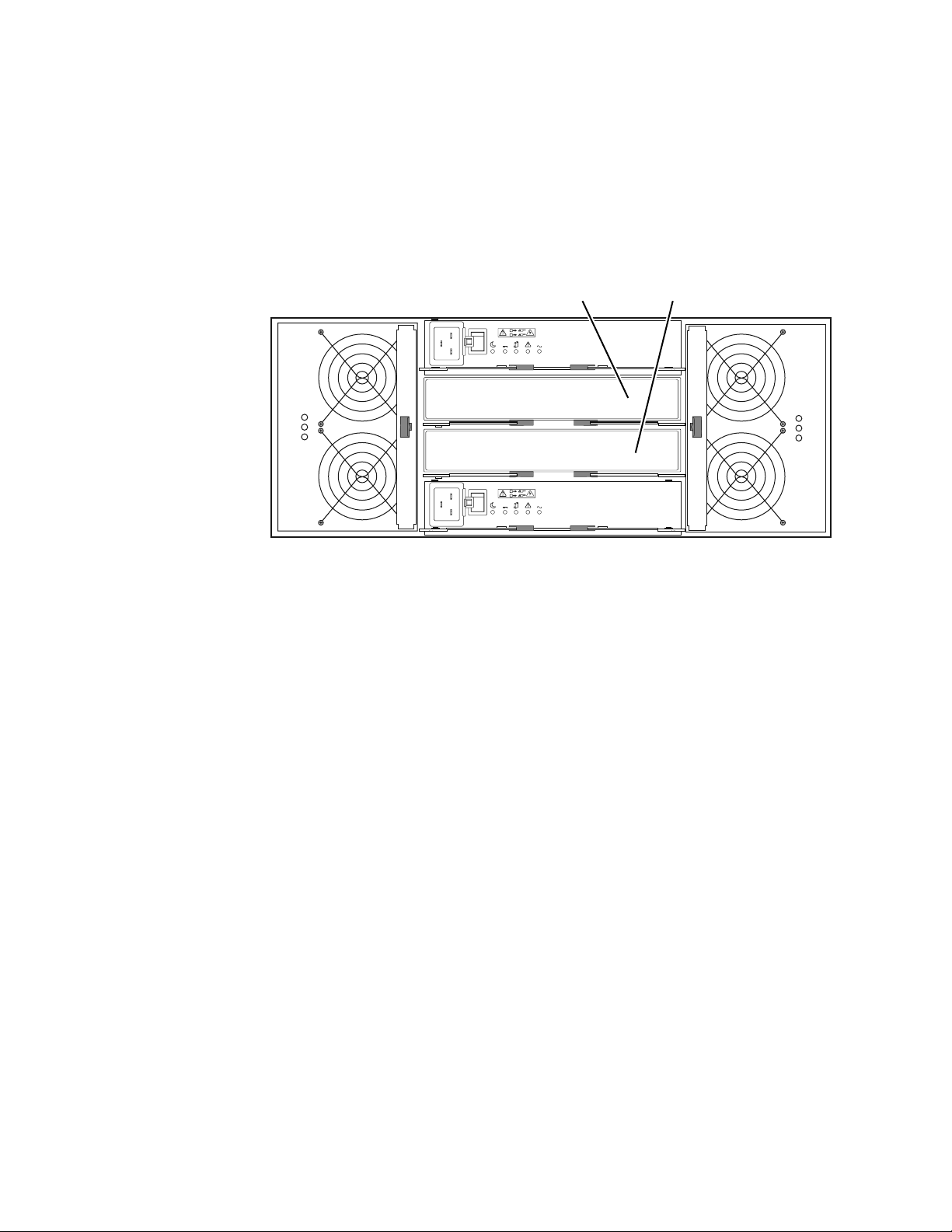
Enclosure ID
Each controller and ESM contain two 7-segment numeric LED displays. These
LEDs provide enclosure identification and diagnostic data. The two digits that
comprise the enclosure ID are referred to as x10 and x1 digits. The enclosure ID
provides a unique identifier for each enclosure in the storage system.
IBM DS Storage Manager automatically sets the enclosure ID for each controller.
You can change the enclosure ID setting through IBM DS Storage Manager only.
12 IBM System Storage DCS3860 Storage System: Installation, User's, and Maintenance Guide
Page 31
There are no switches on the enclosure to manually set the enclosure ID. Both
controllers or ESMs have enclosure IDs that are identical under normal operating
conditions.
Figure 7 shows the seven-segment numeric display on the storage expansion
enclosure.
Seven segment
display
SAS out connectorSAS in connector 2SAS in connector 1
2
1
I
O
I
O
Seven segment
display
ACDC
2
1
ACDC
dcsi0054
Figure 7. Location of seven-segment numeric display on ESM
For more information regarding the enclosure ID, see “Enclosure ID Settings” on
page 44 or “Seven-segment numeric display LEDs” on page 68.
Power supplies
The storage expansion enclosure has two removable power supplies that provide
power to the internal components. If one power supply is turned off or
malfunctions, the other power supply maintains electrical power to the storage
expansion enclosure.
Note: To preserve the optimal airflow, do not remove a failed power supply FRU
from the DCS3860 chassis until you are ready to replace it with a new FRU.
Figure 8 on page 14 shows the power supply controls, LEDs, and connectors.
Chapter 1. Introduction 13
Page 32

Power connector
Power switch LEDs
2
1
I
O
I
O
ACDC
2
1
ACDC
Power supply A
Figure 8. Power supply components
Fan assemblies
The storage expansion enclosure has two removable fan assemblies. Each fan
assembly contains two fans. The fan assemblies draw air through the enclosure
from front to back across the drives. The fans provide redundant cooling, which
means that if one of the fans fails, the remaining fan assembly continues to provide
sufficient cooling to operate the storage expansion enclosure. The fan operates at
maximum speed under the following conditions:
v During the first few minutes after power is applied to the DCS3860 enclosure
v When one of the disk drawers is pulled out or not in the closed/latched position
v When one of the fan assemblies fails or is removed from the enclosure
Note: To preserve optimal airflow, do not remove a failed fan assembly FRU from
the chassis until you are ready to replace it with a new FRU.
Figure 9 on page 15 shows the location of the fan assemblies. See “Fan assembly
LEDs” on page 64 for information about the fan assembly status LEDs.
Note: Although both fan assemblies (left and right) are identical, they are seated in
the enclosure in opposite directions. If the fan assembly cannot be fully inserted in
the fan assembly bay, rotate it 180 degrees and reinsert it. There are notches on the
top and bottom of the fan assembly bay. Ensure that the slits on the top and
bottom of the fan assembly align with these two notches before the fan assembly is
fully inserted in the fan bay.
Power supply B
dcsi0056
14 IBM System Storage DCS3860 Storage System: Installation, User's, and Maintenance Guide
Page 33

Fan unit A Fan unit B
2
1
I
O
I
O
ACDC
2
1
ACDC
dcsi0055
Figure 9. Fan assembly components
Figure 10 shows fan assembly airflow through the storage expansion enclosure.
Back
Front
Figure 10. Storage expansion enclosure airflow
Software and hardware compatibility and upgrades
The support portal has the latest publications, firmware, and host software.
The latest DCS3860 controller firmware and NVSRAM, expansion enclosure ESM
firmware, and the drive firmware must be installed to ensure optimal functionality,
manageability, and reliability. You can find the latest publications, firmware, and
host software at www.ibm.com/support/entry/portal.
Software and firmware support code upgrades
Table 2 on page 16 shows the minimum supported software and firmware versions.
To enable support for the DCS3860, ensure that the software and firmware of the
system are of the latest versions.
dcsi0014
Chapter 1. Introduction 15
Page 34

Table 2. Minimum DCS3860 software and firmware versions
Software/firmware Version
DS Storage Manager software 10.86.xx.xx
DCS3860 controller firmware and
NVSRAM
ESM firmware 0393
Drive firmware
07.86.xx.xx
See the latest software and firmware at the IBM System
Storage Support website:
www.ibm.com/support/entry/portal.
For T10 PI, you must use drives that support this feature.
To find the latest Storage Manager software, controller firmware, NVSRAM, ESM
firmware, and drive firmware, check IBM System Storage Support website:
www.ibm.com/support/entry/portal..
For instructions to install the IBM DS Storage Manager V10.83 or later, see the IBM
System Storage DS
®
Storage Manager Version 10.8 Installation and Host Support Guide.
If you need further assistance, contact your IBM reseller or IBM representative to
find out which controller firmware is to be used for DCS3860 attachment.
For more information about the DCS3860 parts replacement procedure and
problem troubleshooting, see “Solving problems” on page 123.
Determining firmware versions
There are two different methods to determine the DCS3860 storage system and
EXP3800 expansion enclosure firmware versions. Each method uses the IBM DS
Storage Manager that manages the DCS3860 storage system with the attached
storage expansion enclosure.
Method One:
1. In the Subsystem Management window, click the Summary tab.
2. In the Monitor section, click View Storage Subsystem Profile. The Storage
Subsystem Profile window opens. Scroll through the data to locate the
following information:
Note: The Storage Subsystem Profile window shows information for the entire
system. Therefore, you might have to scroll through a large amount of information
to locate the firmware version numbers.
DCS3860 storage system
v NVSRAM version
v Firmware version
Drives
v Drive firmware version
EXP3800 expansion unit
v ESM card firmware version
Method Two:
16 IBM System Storage DCS3860 Storage System: Installation, User's, and Maintenance Guide
Page 35

Specifications
To obtain the controller firmware version:
Go to the Subsystem Management window. In the left pane of the Physical
View tab, click the Controller icon. The properties of the controller are
displayed in the right pane of the Physical View tab.
You must perform this step for every controller.
To obtain the drive firmware version:
Go to the Subsystem Management window. In the left pane of the Physical
View tab, click the Drive icon. The properties of the drive are displayed in
the right pane of the Physical View tab.
You must perform this step for every drive.
To obtain the ESM and drive enclosure component firmware versions:
1. Go to the Subsystem Management window. In the left pane of the
Physical View tab, click the Drive Enclosure Component icon. The
Drive Enclosure Component Information window opens.
2. In the left pane, click the ESM icon. The ESM information is displayed
in the right pane of the Drive Enclosure Component Information
window.
3. Locate the firmware version of each ESM in the drive enclosure.
This section provides site specifications for the storage expansion enclosure. Before
installing a storage expansion enclosure, you must check whether your planned
installation site meets these requirements, or prepare the site so that it meets these
requirements. Preparations might involve meeting area requirements,
environmental requirements, and electrical requirements for storage expansion
enclosure installation, service, and operation.
Area requirements
The floor space at the installation site must be strong enough to support the
weight of the storage system and associated equipment; have sufficient space to
install, operate, and service the storage system; and have sufficient ventilation.
Dimensions
The DCS3860 conforms to the 19-inch rack standard. Table 3 lists the dimensions of
the DCS3860 with all its components.
Table 3. DCS3860 storage expansion enclosure dimensions (with disk drives).
Height Width Depth
6.93 in. (17.6 cm) 19 in. (48.3 cm) 34.1 in. (86.6 cm)
Weight
The total weight of the storage enclosure depends on the configuration of the unit.
Table 4 on page 18 lists the maximum, empty, and shipping weights for the
DCS3860 in different configurations. Table 5 on page 18 lists the weight of each
component.
1
Chapter 1. Introduction 17
Page 36

Table 4. DCS3860 weights.
Weight
Unit
DCS3860 storage
system
EXP3800 expansion
Maximum
1
103.16 kg (227.4 lb) 58.56 kg (129.1 lb)
101.0 kg (222.6 lb) 56.3 kg (124.2 lb)
Empty
2
Shipping
111.06 kg (244.8 lb)
unit
1
Chassis with all FRUs and 60 drives.
2
Chassis without drives but with midplane and all FRUs.
3
Includes the DCS3860, support rails, power cords, publications, 20 drives, shipping
material, and the pallet.
Table 5. DCS3860 component weights
Unit Weight
EXP3800 storage expansion enclosure with
19.5 kg (43 lb)
midplane only (all FRUs removed)
Drive drawer (includes cable chains but no
5.2 kg (11.5 lb)
drives)
3.5 inch disk expansion enclosure 0.7 kg (1.6 lb)
Power supply 2.5 kg (5.5 lb)
Fan assembly 1.1 kg (2.4 lb)
ESM 1.5 kg (3.4 lb)
Controller with cache battery backup and
3.06 kg (6.75 lb)
SAS HIC
3
Shipping dimensions
The DCS3860 is shipped on a pallet. Table 6 and Table 7 list shipping carton
dimensions.
Table 6. DCS3860 shipping carton dimensions when shipped with drives.
Width Depth Height
24 in. (61 cm) 39.75 in. (101 cm) 29.5 in. (74.9 cm)
Table 7. DCS3860 shipping carton dimensions when shipped without drives.
Width Depth Height
24 in. (61 cm) 39.75 in. (101 cm) 19 in. (48.2 cm)
1
The height shown includes the height of the pallet.
Environmental requirements and specifications
This section contains information about the environmental requirements and
specifications for the storage expansion enclosure. It includes temperature and
humidity, altitude, airflow and heat dissipation, shock and vibration requirements,
and acoustic noise levels.
1
1
18 IBM System Storage DCS3860 Storage System: Installation, User's, and Maintenance Guide
Page 37

Temperature and humidity
Table 8 lists the acceptable temperature and humidity ranges for the DCS3860
storage expansion enclosure when in storage or in transit.
Note: Substantial deviations from the suggested operating range, in either
direction, if sustained for extended periods of time, expose the unit to greater risk
of failure from external causes.
Table 8. Temperature and humidity requirements for storage expansion enclosure when in
storage or in transit.
Condition Parameter Requirement
Temperature Operating range 10° - 35° C (50° - 95° F)
Maximum rate of change 10° C (18° F) per hour
Storage range -10° - 65° C (14° - 149° F)
Maximum rate of change 15° C (27° F) per hour
Transit range -40° C to 65° C (-40° F to 149°
F)
Maximum rate of change 20° C (36° F) per hour
Relative humidity (no
condensation)
Operating range 20% to 80%
Storage range 10% to 90%
Transit range 5% to 95%
Maximum dew point 26° C (79° F)
Maximum gradient 10% per hour
Altitude
Table 9 lists the acceptable altitudes for operating, storing, and shipping the
DCS3860.
Table 9. DCS3860 altitude ranges
Environment Altitude
Operating 30.5 m (100 ft.) below sea level to 3000 m
(9,840 ft) above sea level
Storage 30.5 m (100 ft.) below sea level to 3000 m
(9,840 ft) above sea level
Transit 30.5 m (100 ft.) below sea level to 12,000 m
(40,000 ft.) above sea level
Airflow and heat dissipation
Figure 11 on page 20 shows the intended airflow for the DCS3860. Allow at least 30
inches in front of the storage system and at least 24 inches behind the storage
system for service clearance, ventilation, and heat dissipation.
Chapter 1. Introduction 19
Page 38

Back
Front
Figure 11. DCS3860 airflow
Table 10 lists the KVA, watts, and Btu calculations. These values assume that the
power supplies have an 88 percent efficiency and a power factor of 0.99. These
tabulated power and heat dissipation values are typical for the storage system.
Maximum configuration units are typically operated at higher data rates, have
larger random access memory (RAM) capacities, or have different host interface
boards.
Table 10. DCS3860 power and heat dissipation
Parameter KVA Watts (ac) Btu per hour
DCS3860 storage
system
EXP3800 expansion
unit
1.177 1108.6 3791
.895 802 2736
Shock and vibration requirements
Operational Shock: The DCS3860 can withstand the following shock. Subjecting
the equipment to a single shock pulse with the following characteristics simulates
this level of shock:
v Velocity change = 20 inches per second
v Wave form = 1/2 Sine, 10 g @5ms
Operational Vibration (Random): While in its normal operating position, the
DCS3860 continues operating when subjected to a random vibration test using the
criteria shown in Table 11. This test uses the indicated spectral power density for
30 minutes in each of the three axes.
Table 11. Random vibration power spectral density
Hz 5 17 150 200 500
2
/Hz 9.0x10
g
20 IBM System Storage DCS3860 Storage System: Installation, User's, and Maintenance Guide
-5
3.0x10
-4
3.0x10
-4
9.0x10
-5
9.0x10
-5
Page 39

Acoustic noise
Table 12 lists the maximum sound levels emitted by the storage system.
Table 12. DCS3860 sound levels
Measurement Level
Sound power (normal operation) 7.0 bels
Sound power (normal operation with 4 TB
drives)
These levels are measured in controlled acoustical environments according to ISO
7779 and are reported in accordance with ISO 9296. The declared sound power
levels indicate an upper limit, below which a large portion of machines operate.
Sound pressure levels in your location might exceed the average 1-meter values
stated because of room reflections and other nearby noise. See “Noise” on page 164
to know more about measures needed to ensure hearing protection of the
operating personnel.
Electrical requirements
This section provides information regarding site power and wiring, storage system
AC power requirements, and power cord routing instructions. Consider the
following factors when preparing the installation site:
v Protective ground – Site wiring must include a protective ground connection to
the AC power source.
7.2 bels
Note: Protective ground is also known as safety ground or chassis ground.
v Circuit overloading – Power circuits and associated circuit breakers must
provide sufficient power and overload protection. To prevent possible damage to
the unit, isolate its power source from large switching loads (such as air
conditioning motors, elevator motors, and factory loads).
v Power failures – If power fails, the unit automatically performs a power on
recovery sequence without operator intervention after power is restored.
Attention: The DCS3860 does not support 90-136V AC sources. It supports
200-240 V AC sources only. Ensure that the AC input is appropriate for the
DCS3860 before turning on the power switches.
Table 13. DCS3860 AC power requirements.
AC Power Requirements Range
Nominal Voltage 180 - 264 V AC
Frequency (Hertz) 50 - 60 Hz
Idle Current 7.55 A
Maximum Operating Current 7.79 A
Maximum Surge Current 7.82 A
a.
Typical voltage: 220 V AC, 50 Hz
b.
While the system is idle, it still performs background data scrubbing on all the drives.
However, during regular I/O the system benefits from cache, which uses less power.
a,b
a
a
Note: The DCS3860 power supplies have C20 power inlets.
Chapter 1. Introduction 21
Page 40

Power and site wiring requirements for models with power supply and fan units
The storage expansion enclosure uses wide-ranging redundant power supplies that
automatically accommodate voltages to the power source. The power supplies
operate within the ranges specified in Table 13 on page 21. The power supplies
meet standard voltage requirements for both domestic (inside USA) and
international (outside USA) operations. They use standard industrial wiring with
line-to-neutral or line-to-line power connections.
The agency voltage and current ratings for the DCS3860 storage expansion
enclosure are 200 V
AC - 240 V AC and 7.79 A - 7.64 A.
Power recovery after a power failure: After normal power is restored, the storage
expansion enclosure performs power-up recovery procedures automatically
without operator intervention.
Power cords and receptacles: The DCS3860 ships with either two IEC C19 to C14
jumper cords or two IEC C19 to C20 jumper cords. The C19 plug connects to the
DCS3860 power supply and the other end is used to connect to the rack PDU
outlets. It is not shipped with the power cords that can be used to connect it
directly to an electrical outlet in the destination country. You must purchase the
power cords that are appropriate for use in a typical outlet in the destination
country. See Chapter 10, “Power cords,” on page 157 for more information.
Heat output, airflow, and cooling
The system has a hot aisle and cold aisle requirement for disk system reliability.
See “Airflow and heat dissipation” on page 19 for heat output, airflow, and cooling
specifications.
Note: In general, disk system reliability tends to decrease as the ambient
temperature of the environment in which it is being used increases.
When racks that contain many storage expansion enclosures are to be installed
together, the following requirements must be met to ensure that the storage
expansion enclosures are adequately cooled:
v Air enters at the front of the rack and leaves at the back. To prevent the air that
is leaving the rack from entering the intake of another piece of equipment, you
must position the racks in alternate rows, back-to-back, and front-to-front. This
arrangement is known as cold aisle and hot aisle and is shown in Figure 12 on
page 23.
v Where racks are in rows, each rack must touch the rack that is next to it to
reduce the amount of hot air that can flow around from the back of the rack into
the intakes of the storage expansion enclosures that are in that rack. You must
use Suite Attach Kits to completely seal any gaps that remain between the racks.
For details about Suite Attach Kits, contact your marketing representative.
v Where racks are in rows front-to-front or back-to-back, a gap of at least 1220 mm
(48 in.) must separate the rows across the cold aisle.
v To ensure correct airflow in each rack, the rack filler plates must be installed in
unused positions. Also, all the gaps in the front of the racks must be sealed,
including the gaps between the storage expansion enclosures.
22 IBM System Storage DCS3860 Storage System: Installation, User's, and Maintenance Guide
Page 41

T42 racks
back
front
1220 mm cold
aisle width
Air
Cold aisle
front
T42 racks
back
conditioner
Hot aisle
back
T42 racks
front
Airflow
Figure 12. Example of cold aisle/hot aisle rack configuration
Perforated tiles
or gratings
2440 mm between
center lines of hot
and cold aisle
Chapter 1. Introduction 23
Page 42

24 IBM System Storage DCS3860 Storage System: Installation, User's, and Maintenance Guide
Page 43

Chapter 2. Installing the DCS3860
This section provides information that you need to prepare the storage enclosure
for installation into a rack cabinet.
“Installation overview” provides an overview of the storage enclosure installation
process. Read this overview before you begin the installation.
Installation overview
Attention: Refer to “Safety” on page ix for general safety instructions and
Chapter 9, “Specifications for non-IBM rack installation,” on page 149 before
performing any installation or service procedures.
CAUTION:
1. The weight of this unit in the drive-ready state (without drive modules
installed) is 56.7 kg (125 lb). Fully configured (with 60 drive modules
installed) the unit weighs 102.1 kg (225 lb). It takes three people to push the
enclosure out of the custom-designed package. You can also use a lift tool.
2. A fully populated DCS3860 weighs approximately 102.1 kg (225 lb). Before
you install it, verify that the additional weight of the chassis does not exceed
the rack’s weight limit or unbalance the rack cabinet. When you calculate the
additional weight, include the weights of all components that can potentially
be added, to avoid overloading in the future.
Installation sequence
1. Prepare the installation site and the rack cabinet.
2. Unpack the DCS3860 and other hardware from the shipping box. See
“Preparing for installation” on page 26.
Attention:
a. Because of the size and weight of the storage enclosure as shipped, you
b. Before you move or relocate a rack that contains DCS3860 storage
3. Install the support rails in the rack. See “Installing the support rails” on page
30.
4. Install the DCS3860 storage enclosure in the rack. See “Installing the DCS3860
into the rack cabinet using a lift tool” on page 35 if you have ordered a lift
tool. See “Installing the DCS3860 into the rack cabinet without using a lift
tool” on page 38 if you do not have a lift tool.
5. Install disk drives in the DCS3860 storage enclosure. See “Installing the
DDMs” on page 39.
6. If there are other DCS3860 storage enclosures to be installed in the same rack,
repeat step 3 to step 5 for the other DCS3860 units.
require three people to push the enclosure out of its custom-designed
package. You can also use a lift tool and push the enclosure onto the lift
tool.
enclosures, see “Relocating the DCS3860” on page 52 for additional
information.
© Copyright IBM Corp. 2013 25
Page 44

7. Install the power supply cables to the DCS3860s. Ensure that the DCS3860
power supplies are connected to 240 V AC sources only. See “Cabling the
power supply” on page 52.
8. Cable the DCS3860 Storage system to any storage expansion enclosures. See
Chapter 3, “Cabling the DCS3860 storage system,” on page 43.
9. Install the IBM DS Storage Manager host software to manage the DCS3860
Storage system. See “Software and hardware compatibility and upgrades” on
page 15 for the appropriate version. For instructions to install the DS Storage
Manager software, see the IBM System Storage DS Storage Manager Version 10.8
Installation and Host Support Guide for the applicable operating system.
10. Turn on the DCS3860 (if you have not done so already). See “Powering on the
DCS3860” on page 56.
11. Upgrade the controller firmware. See “Finding Storage Manager software,
controller firmware, and README files” on page xvi for more information.
Handling static-sensitive devices
Attention: Static electricity can damage electronic devices and your system. To
avoid damage, keep static-sensitive devices in their static-protective packages until
you are ready to install them.
v Limit your movement, so that it does not cause static electricity to build up
around you.
v Handle the device carefully, holding it by its edges or its frame.
v Do not touch solder joints, pins, or exposed printed circuitry.
v Do not leave the device where others can handle and possibly damage the
device.
v While the device is still in its static-protective package, touch it to an unpainted
metal part of the system unit for at least 2 seconds. This drains static electricity
from the package and from your body.
v Remove the device from its package and install it directly into your system unit
without setting it down. If it is necessary to set the device down, place it in its
static-protective package. Do not place the device on your system unit cover or
on a metal table.
v Take additional care when handling devices during cold weather because
heating reduces indoor humidity and increases static electricity.
Preparing for installation
Before installing the storage enclosure, create a detailed plan of how this unit will
be used in your storage configuration. The plan should include determining RAID
levels, failover requirements, operating systems to be used, and total storage
capacity requirements.
1. Prepare the site according to the area, environmental, power, and site
requirements. For more information, see “Specifications” on page 17.
2. Move the storage enclosure to the site.
26 IBM System Storage DCS3860 Storage System: Installation, User's, and Maintenance Guide
Page 45

Attention:
a. Because of the size and weight of the storage enclosure as shipped, you
require three people to push the enclosure out of its custom-designed
package. You can also use a lift tool and place the enclosure onto the lift
tool. Alternatively, you can reduce the weight of the storage enclosure and
then push the enclosure out of the package, as follows:
v Remove two power supplies and ensure that the hard disk drive drawers
are empty; then, two people can lift the storage enclosure.
v Ensure that the hard disk drive drawers are empty. Remove two power
supplies, two fan assemblies, two controllers or environmental services
modules, and a minimum of three of the five unpopulated hard disk
drive drawers; then, two people can lift the storage enclosure.
See “Weight” on page 17 to know the weight of each component.
b. Before you move or relocate a rack that contains DCS3860 storage
enclosures, see “Relocating the DCS3860” on page 52 for additional
information.
Note: For more information about how to use a lift tool, see the documentation
that came with the lift tool.
3. Remove the storage enclosure from its shipping container and check the
contents (see “Unpacking the shipping box”). If any items are missing, contact
your IBM reseller before you proceed with installation.
4. Verify that you have the correct version of the IBM DS Storage Manager
software.
5. Continue with “Preparing the site” on page 29.
Unpacking the shipping box
Important: You must install the support rails in the rack cabinet before you install
the storage enclosure. Hence, do not remove the storage enclosure from the
shipping box until the support rails are installed.
1. Remove the following items from the shipping box. Do not remove the
DCS3860 from the shipping box at this time.
v Six full or empty boxes of DDMs (if you have ordered DDMs, and also
ordered DDMs to be included in the shipping box. You can also order the
DDMs to be shipped separately.)
Note: The DDMs are packaged 10 per box. The minimum order is 20 DDMs,
so at least two of the boxes are full. If you ordered less than the maximum
number of 60 DDMs, one or more of the boxes will be empty.
v Box containing the mounting hardware kit
v Box containing storage enclosure handles
v Box containing the power cords and documentation
2. Check the items in the preceding list to ensure that you have received all the
necessary parts. See the “Inventory list” for the parts that are included with the
storage enclosure.
Inventory list
If any items are missing or damaged, contact your place of purchase.
Note:
1. The illustration might differ slightly from your hardware.
Chapter 2. Installing the DCS3860 27
Page 46
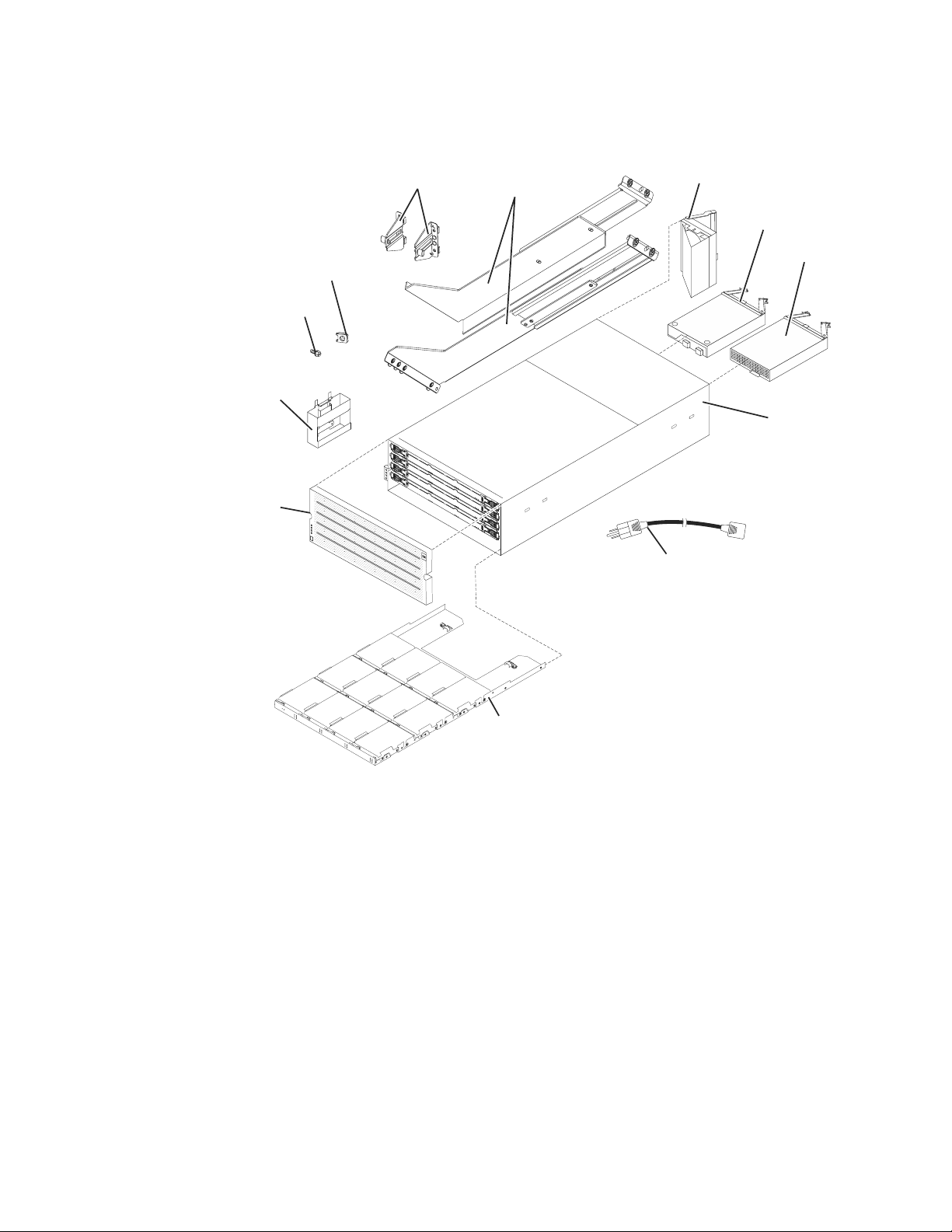
2. Depending on your DCS3860 order, your shipping box might contain additional
materials that are not shown in the following illustration.
Fan
assembly (2)
Power
supply (2)
Storage
enclosure
Controller
or ESM (2)
Clip nuts (4)
M5 x 8 mm
screws (16)
Handles (4)
Bezel
Rear brackets
Support rails
PDU jumper cord
Drive drawer
assembly (5)
After you unpack the DCS3860, verify that you have the following items:
v 4U-high storage enclosure (1)
– Drive drawer assemblies (5)
– Fan assemblies (2)
– Power supplies (2)
– Controllers (2), if you ordered 1813-86C
– ESMs (2), if you ordered 1813-80E
v Handles (4), packaged in a smaller box inside the shipping box
v DDMs (20 or more, depending on your DCS3860 order), packaged in a smaller
box inside the shipping box, if you have ordered the DDMs to be shipped with
the storage system.
v Bezel (1)
v Rack-mounting hardware kit (1), packaged in a smaller box inside the shipping
box, including:
– Rails (2), right and left assembly
– Rear brackets (2)
dcsi0057
28 IBM System Storage DCS3860 Storage System: Installation, User's, and Maintenance Guide
Page 47

– M5 black hex-head slotted screws (16)
Note: The screws are either preinstalled in the support rails or packaged in a
plastic bag.
– Washers (8)
– Clip nuts (4)
Important: The DCS3860 does not ship with region-specific ac power cords. You
must obtain the IBM-approved power cords for your region. For more information,
see Chapter 10, “Power cords,” on page 157.
Tools
Before you install the storage enclosure, the installation area must have an internet
connection, and you must have the following tools:
v A cart to hold the storage enclosure and its components
v Labels for the cable connectors
v A medium flat-blade screwdriver
v A No. 2 Phillips screwdriver or an M5 hex driver
v Anti-static protection
Tools and hardware required
These might include:
v A portable mechanized lift (optional)
v A number 2 Phillips screwdriver
v An M5 hex nut driver
v A medium flat-blade screwdriver
v anti-static protection (such as a grounding wrist strap)
v The rack power jumper cords that are shipped with the storage enclosure
v Rack-mounting hardware that ships with the storage enclosure
Preparing the site
For information about interface cables and connections, see Chapter 3, “Cabling the
DCS3860 storage system,” on page 43.
Floor space: The floor area at the installation site must satisfy the following
prerequisites:
v Enough stability to support the weight of the fully configured storage enclosure
and associated systems
v Sufficient space to install the storage enclosure
Weight: The weight of the storage enclosure depends on the number of
components that are installed. A fully configured storage enclosure with two
power supplies, two fan assemblies, two controllers or ESMs, and 60 hard disk
drives weighs up to 228.4 lb (103.6 kg). For more information, see “Weight” on
page 17.
Other Factors: Before you prepare the rack:
v Install uninterruptible power supply (UPS) devices.
v Install host bus adapters (HBAs), switches, or other devices, if applicable.
v Route interface cables from the hosts or switches to the installation area.
Chapter 2. Installing the DCS3860 29
Page 48

v Route main power cords to the installation area.
Preparing the rack
v When DCS3860 enclosures are to be plant or field integrated into the IBM racks,
the rack must be configured with PDU power cords rated for 240 volt electrical
service.
v IBM does not support the ruggedized rack feature for the 2101-200 rack when it
is used with the DCS3860. The DCS3860 does not fit in the 2101-200 rack if the
ruggedized rack feature is installed.
v Do not install the DCS3860 above EIA Unit position 32 in any rack. Installing the
DCS3860 above U position 32 requires a ladder and is not supported.
v If you are using a non-IBM rack or cabinet, review the information in Chapter 9,
“Specifications for non-IBM rack installation,” on page 149.
v Do not extend more than one device out of the rack cabinet at the same time.
v To ensure proper airflow, do not block the air vents; 15 cm (6 in.) of air space is
sufficient.
v To ensure rack stability, load the rack starting at the bottom.
v If you install multiple components in the rack, do not overload the power
outlets.
v Always connect the storage enclosure to a properly grounded outlet.
Complete the following steps to prepare the rack before you install the storage
enclosure:
1. Move, unpack, and level the rack at the installation site (if needed).
2. Remove the external rack panels.
3. If necessary, stop all I/O activity to the devices in the rack.
4. If necessary, turn off all drive enclosure and rack power. Disconnect existing
power, network, and other external cables.
5. Install any additional interface cables and power cables.
After you have completed these steps, continue with “Installing the support rails.”
Installing the support rails
Note: Duplicate copies of the rack mounting templates are provided in Chapter 8,
“Rack mounting template,” on page 145. If you want to tear out the templates
from this document for easier use, use the copies in Chapter 8, “Rack mounting
template,” on page 145 rather than the copies provided in this section.
Use the following templates (Figure 13 on page 31 and Figure 14 on page 32) to
identify the proper locations for inserting M5 screws when mounting the support
rails and DCS3860 to a rack. The locations for the M5 screws are highlighted in the
templates.
The DCS3860 is 4U high. Align the template with the rack at a U boundary. U
boundaries are shown as horizontal dashed lines in the rack mounting templates.
Note: The mounting holes that are shown in the following templates are round.
The holes in the rack might be round, square, or threaded.
30 IBM System Storage DCS3860 Storage System: Installation, User's, and Maintenance Guide
Page 49

4U
3U
Install after you mount enclosure
Install after you mount enclosure
Install first
Install after you mount enclosure
Install after you mount enclosure
FRONT
4U
3U
Install first
2U
Rack Mounting
Template
Rail assembly
(front left)
1U
Install first Install first
0U
Figure 13. Front rack mounting template
Rail assembly
(front right)
2U
1U
0U
dcsi0069
Chapter 2. Installing the DCS3860 31
Page 50

4U
4U
Rear bracket Rear bracket
3U
2U
1U
Rack Mounting
Rail assembly
(rear left)
3U
REAR
Template
2U
Rail assembly
(rear right)
1U
Rail mounting guide
0U
Printed in the U.S.A
Figure 14. Rear rack mounting template
Before installing the DCS3860 in a rack, you must install the rails and
rack-mounting hardware that is shipped with your storage enclosure. The DCS3860
requires an Electronic Industries Association (EIA) 310-D Type A 19-inch rack
cabinet. The distance between EIA rails, from the front to the rear of the rack,
ranges between 76 cm (30 in.) and 81.28 cm (32 in.). This rack conforms to the EIA
standard. Where you place the support rails in the rack depends on where you
intend to place the storage enclosure.
Use the front and rear rack-mounting templates in Figure 13 on page 31 and
Figure 14 to align the support rails and rear brackets with the correct rack holes. If
the support rails will be installed above an existing storage system or storage
enclosure, position the DCS3860 support rails directly above it. If the support rails
32 IBM System Storage DCS3860 Storage System: Installation, User's, and Maintenance Guide
®
0U
Page 51

will be installed below an existing storage system or storage enclosure, allow 178
mm (7 in.) of vertical clearance for the DCS3860.
Note: For proper weight distribution, install the support rails as low in the rack
cabinet as possible. The rack cabinet must have a minimum depth of 100 cm (40
in.). If you are using a non-IBM rack or cabinet, review the information in
Chapter 9, “Specifications for non-IBM rack installation,” on page 149.
Complete the following steps to install the left and right support rails in the rack
cabinet:
1. Ensure that the rack has already been installed.
2. Ensure that a stabilizer has been attached correctly to the bottom front of the
rack to prevent the rack from tipping forward while the storage enclosure is
being installed.
Refer to the installation and service guide, or equivalent, for the rack as
required.
3. Locate the two support rails, eight M5 screws, and eight washers that are
supplied with the storage enclosure.
Note: The screws and washers might already be attached to the support rails.
If so, remove them from the support rails.
4. Starting with the left support rail, loosen the two rail adjustment screws with
a medium flat-blade screwdriver. The adjustment screws are used to lock the
support rails at a certain length.
Note: The support rails are not marked as left or right. However, each rail can
be mounted correctly on only one side of the rack cabinet. The rails should be
mounted with the alignment pin at the rear of the rack.
Rear
Screws
Front
Rear rack
cabinet rail
Front rack
cabinet rail
Screws
Support
rail lip
Rail adjustment
screws
5. Hold the front of the left support rail against the inside of the front rack
cabinet support flange, and extend the rear of the support rail until it makes
contact with the rear rack cabinet support flange. The alignment pins at the
rear of the support rail slide into the mounting holes at the rear of the rack
cabinet. The wider end of the support rail must be positioned at the front of
the rack cabinet.
6. From the front of the rack cabinet, with the support-rail flanges positioned
inside the rack cabinet support rail assemblies, insert two M5 screws with
washers through the front of the cabinet and screw them into the support rail
Chapter 2. Installing the DCS3860 33
Page 52

front flange. Ensure that you use a washer when you install an M5 screw
through a square hole on a rack-mounting flange.
Attention: Ensure that the screws are tight enough to support the weight of
the storage enclosure, but do not completely tighten the screws yet.
7. Ensure that the holes in the rail above and below the top mounting screw are
visible through the holes of the rack flange and tighten the two M5 screws to
secure the front of the rail to the rack flange.
8. From the rear of the rack cabinet, insert two M5 screws with washers through
the rear of the cabinet and screw them into the support rail rear flange.
9. Tighten the two rail adjustment screws with a medium flat-blade screwdriver.
10. Repeat steps 4 on page 33 through 9 for the right support rail.
Note: Because the mounting holes on the rack are not always the same size as
the mounting screws, the lip of each of the support rails might not line up
evenly. Make minor adjustments to ensure that the lip of the left and right
support rails are lined up evenly on the racks. Failure to do so will cause the
storage enclosure to fit unevenly in the rack.
11. Locate the two rear brackets, four M5 screws, four washers, and four clip nuts
that are supplied with the storage enclosure.
12. Install the rear brackets at the rear of the rack as shown in the following
illustration, using the M5 screws, washers, and clip nuts to secure the brackets
to the rack mounting holes. Ensure that you clip the nuts on the rack. Do not
tighten the screws until the DCS3860 is installed in the rack (see 8 on page
37).
13. Continue with “Installing the DCS3860 into the rack cabinet using a lift tool”
on page 35 or “Installing the DCS3860 into the rack cabinet without using a
lift tool” on page 38.
34 IBM System Storage DCS3860 Storage System: Installation, User's, and Maintenance Guide
Page 53

Installing and removing the handles
After you install the storage enclosure in the rack cabinet and remove the handles,
store the handles for future use.
Installing the handles
1. Locate the box of handles.
2. To install a handle on the storage enclosure, place notch at the bottom of the
handle in the opening in the storage enclosure chassis, and push the handle in
and up until the latch at the top of the handle secures the handle to the chassis.
3. Repeat step 2 for the remaining handles.
Removing the handles
Complete the following steps to remove the handles from the storage enclosure:
1. Release the latch with your thumb and pull down and away from the unit.
2. Repeat step 1 for the three remaining handles.
Handle
Thumb
latch
3. Store the handles for future use.
Installing the DCS3860 into the rack cabinet using a lift tool
Complete the following steps to install the storage enclosure if you have acquired a
lift tool:
1. Prepare the storage enclosure for installation:
a. Position the lift tool so that it faces one side of the shipping box.
b. Remove the foam shipping material from the sides and ends of the storage
enclosure.
c. If necessary, cut away sides of the shipping box so that the lift tool has
access to the storage enclosure.
Chapter 2. Installing the DCS3860 35
Page 54

d. Open the plastic bag and tuck it under the storage enclosure. The plastic
bag reduces friction and makes it easier to slide the unit out of the shipping
box onto the lift tool, then out of the lift tool and into the rack cabinet.
e. Install the four handles on the sides of the storage enclosure. See “Installing
and removing the handles” on page 35 for detailed instructions.
102 kg (225 lbs)
56.7 kg (125 lbs)
(12 x 5)
(60X)
Attention:
a. Because of the size and weight of the storage enclosure as shipped, you
require a minimum of three people to push the enclosure out of its
custom-designed package. For more information about the lift tool, see
“Installation overview” on page 25.
b. Before you move or relocate a rack that contains DCS3860 storage
enclosures, see “Relocating the DCS3860” on page 52 for additional
information.
2. Slide the storage enclosure out of the side of the shipping box and onto the lift
tool. Align it in front of the rack.
3. Put the rear edge of the storage enclosure on the support rails.
4. Remove the two handles (one on each side) at the rear of the storage enclosure.
Do not remove the front handles on both sides of the unit.
5. Slide the storage enclosure halfway into the rack and remove the two handles
(one on each side) at the front of the unit.
36 IBM System Storage DCS3860 Storage System: Installation, User's, and Maintenance Guide
Page 55

Rear
Front
6. Install and tighten two M5 screws on each side of the rack, above and below
the top M5 screws, in the front of the storage enclosure to secure the storage
expansion enclosure.
dcsq0003
7. Turn the rear-bracket thumbscrews to attach the rear brackets to the sides of the
storage enclosure. The screw holes are located about 51 mm (2 in.) from the
rack flange.
Note: To align the thumbscrews with the holes in the unit, you might need to
loosen the screws that attach the rear brackets to the rack cabinet.
8. Tighten all of the M5 screws to secure the rear bracket to the rack cabinet.
9. Continue with “Installing the DDMs” on page 39.
Chapter 2. Installing the DCS3860 37
Page 56

Installing the DCS3860 into the rack cabinet without using a lift tool
Complete the following steps to install the storage enclosure if you do not have a
lift tool:
≥ 18 kg (39.7 lb) ≥ 32 kg (70.5 lb) ≥ 55 kg (121.2 lb)
1. Prepare the storage enclosure for installation:
a. Remove the foam shipping material from the sides and ends of the storage
enclosure.
b. If necessary, cut away sides of the shipping box to access the storage
enclosure.
c. Open the plastic bag and tuck it under the storage enclosure. The plastic
bag reduces friction and makes it easier to move the unit out of the
shipping box and then into the rack cabinet.
d. Install the four handles on the sides of the storage enclosure. See “Installing
and removing the handles” on page 35 for detailed instructions.
2. Lift the storage enclosure off the side of the shipping box. Align it in front of
the rack.
3. Put the rear edge of the storage enclosure on the support rails.
4. Remove the two handles (one on each side) at the rear of the storage enclosure.
Do not remove the front handles on both sides of the unit.
5. Slide the storage enclosure halfway into the rack and remove the two handles
(one on each side) at the front of the unit.
Front
6. Install and tighten two M5 screws on each side of the rack, above and below
the top M5 screws, in the front of the storage enclosure to secure the storage
expansion enclosure.
38 IBM System Storage DCS3860 Storage System: Installation, User's, and Maintenance Guide
Rear
Page 57

7. Turn the rear-bracket thumbscrews to attach the rear brackets to the sides of the
storage enclosure. The screw holes are located about 51 mm (2 in.) from the
rack flange.
Note: To align the thumbscrews with the holes in the unit, you might need to
loosen the screws that attach the rear brackets to the rack cabinet.
8. Tighten all of the M5 screws to secure the rear bracket to the rack cabinet.
9. Continue with “Installing the DDMs.”
Installing the DDMs
Attention:
1. Potential damage to DDMs - Repeatedly turning the power off and on without
waiting for the DDMs to spin down can damage them. Always wait at least 90
seconds from when you turn off the power until you turn it on again.
2. The installation order within each drawer is from left to right in rows. Slots 1,
4, 7, and 10 must have a drive installed in these locations to ensure that there is
sufficient airflow to the drives (see Figure 15 on page 40). To verify these slots,
check the overlay on the front of each of the five drive drawers. Ensure that the
four drives in each row are adjacent to each other. The long edge of each drive
should touch the drive next to it. To maintain a uniform airflow across all drive
drawers, the storage enclosure must be configured with a minimum of 20
drives, with four drives in the front row of each of the five drive drawers.
dcsq0003
Chapter 2. Installing the DCS3860 39
Page 58
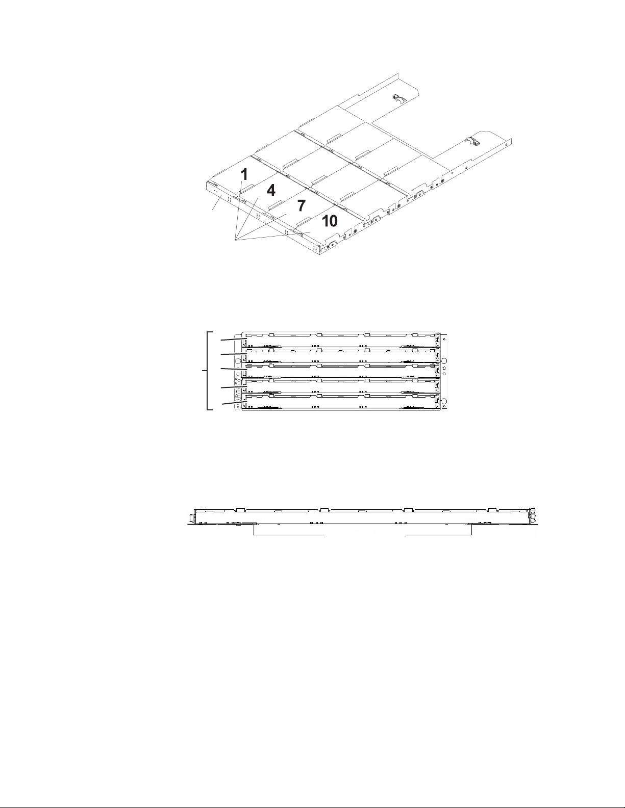
Drive
drawer
Drives
Figure 15. DCS3860 drive drawer with labeled disk drives
The drive drawers are preinstalled in the DCS3860, but the DDMs are shipped
separately from the drive drawers. Ensure that you install the storage enclosure in
the rack cabinet before you install DDMs in the storage enclosure.
1
Drive
drawers
2
3
4
!
5
dcsq0004
Complete the following steps to install the DDMs in the drive drawers:
1. Open the two release levers on the drawer as shown in the illustration.
Starting with the top drive drawer in the storage enclosure, pull the levers on
each side of the drawer out and cam away from the chassis to release the
drawer.
Drive drawer levers
2. With the release levers fully extended, slide the drawer out until it is fully
extended, but do not remove it from the enclosure.
3. Starting with the first DDM, raise the DDM handle to the vertical position.
40 IBM System Storage DCS3860 Storage System: Installation, User's, and Maintenance Guide
dcsq0005
Page 59

Latch
Slots
Raised
buttons
4. Align the raised buttons on the sides with the matching slots in the DDM
channel on the drawer. Lower the DDM down onto the drawer, and rotate the
DDM handle until the DDM snaps into place under the DDM release lever.
Note:
a. If the DDM does not correctly fit into the drive connector on the disk
drawer, push the rear of the drive as you install it.
b. If the storage enclosure is turned on, you must wait for at least 90 seconds
after you install each DDM in the drive drawer. Otherwise, the storage
enclosure might not recognize the new DDM, recognize the DDM as failed,
or recognize the drive as incompatible. In this case, unlatch the DDM, wait
90 seconds, and latch the DDM again.
5. Install the other DDMs in rows from left to right until the drive drawer has a
minimum of four DDMs in the front row of the drive drawer.
6. Push the drive drawer into the storage enclosure until it clicks, and close the
levers on each side of the drawer.
Attention: Ensure that you push both levers back against the drive drawer
completely so that the drive drawer is closed. If the drive drawer is not
completely closed, excess airflow through the unit might cause damage to the
DDMs and you will not be able to open another drawer. If you try to open
another drawer, both drawers might be damaged.
7. Repeat steps 1 on page 40 through 6 for each drive drawer in the
configuration.
8. Position the bezel in front of the storage enclosure as shown in the following
illustration.
Front bezel Latches
9. Align the tabs on the top and bottom of the bezel with the slots on the front
of the storage enclosure, and align the pins on the side of the bezel with the
holes in the storage enclosure. Push the bezel into the front of the unit until
the latches on both sides of the bezel lock it in place.
Chapter 2. Installing the DCS3860 41
Page 60

10. Continue with Chapter 3, “Cabling the DCS3860 storage system,” on page 43.
42 IBM System Storage DCS3860 Storage System: Installation, User's, and Maintenance Guide
Page 61
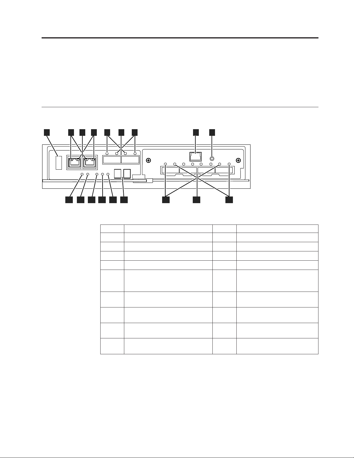
Chapter 3. Cabling the DCS3860 storage system
The section contains information and instructions for cabling the DCS3860 storage
system. After the storage system is installed in its permanent location, you must
cable it to hosts, expansion units, and other external devices, depending on your
hardware configuration.
Controller connectors (with SAS host interface card)
5
3
1
2
6
4
7
8 9
13
12
11
10
Figure 16. DCS3860 storage system
Table 14. Legend to the DCS3860 storage system diagram
Number Description Number Description
1 USB port 10 Battery fault LED
2 Two Ethernet ports 11 Battery charging LED
3 Link rate 12 Service Action Allowed LED
4 Link activity 13 Controller Fault LED
5 Two 6 Gbps SAS expansion ports
6 Fault indicator (for the SAS
7 Activity indicator (for the SAS
8 Serial port 17 Fault indicator (for the SAS host
9 Password reset button 18 Activity indicator (for the SAS
14
15
SAS Host port 1, 2, 3, and 4 on Host Interface Card
Each of the DCS3860 host ports is a x4 multilane, 6 Gbps universal
mini-SAS port. Connect a SAS cable from your host system SAS host bus
adapter to a host port on each controller.
17
(port 1 on the left and port 2 on the
right)
expansion port)
expansion port)
16
18
14 Cache active LED
15 Seven segment status display
16 Four 6 Gbps SAS host ports
dcsi0045
port)
host port)
Expansion port 1 and 2
Expansion port is a x4 multilane SAS port. Connect a SAS cable to this
port and to a drive expansion enclosure.
© Copyright IBM Corp. 2013 43
Page 62
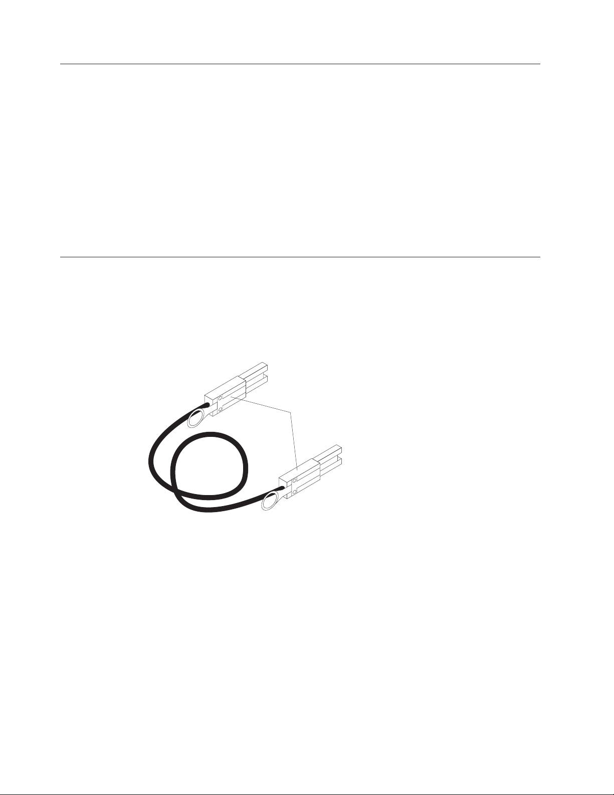
Enclosure ID Settings
The enclosure ID is a unique two-digit identifier for each enclosure in the storage
system configuration. In a dual controller or ESM configuration, both enclosure IDs
are identical under normal operating conditions. Each DCS3860 storage system and
EXP3800 expansion enclosure in the storage system configuration must have a
unique storage enclosure ID.
The controller automatically sets the enclosure ID. You can change the setting
through the DS Storage Manager software, if necessary. The range of supported
enclosure ID settings is 0 through 99. The enclosure ID is normally set to a value of
00 at the factory.
The enclosure ID is displayed on the seven-segment numeric display located on
the back of each controller and ESM.
Working with SAS cables
Use a 1M or 3M (1-meter or 3-meter) SAS cable with a mini-SAS 4x multilane SAS
connector at each end. Use this cable to connect a controller host port to a host
HBA and the drive expansion port to a storage enclosure.
The following illustration shows the 1M and 3M mini-SAS cable.
Figure 17. Mini-SAS cable
Mini-SAS
connectors
The 1M and 3M SAS cables have a universal key connector that enables the cable
to be used in all mini-SAS ports.
44 IBM System Storage DCS3860 Storage System: Installation, User's, and Maintenance Guide
Page 63
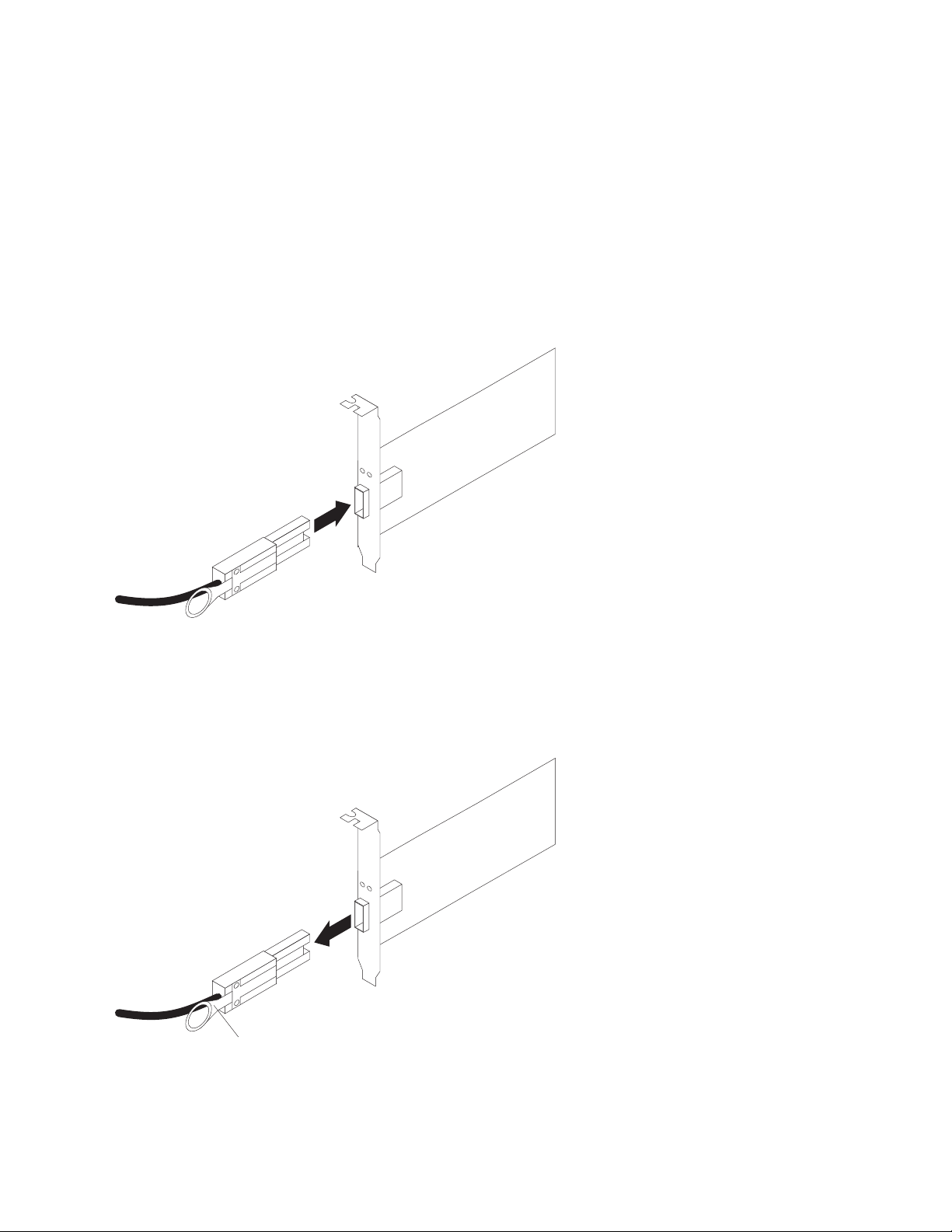
Attention: To avoid damage to the SAS cables, consider the following
precautions:
v When you route the cable along a folding cable-management arm, leave enough
slack in the cable.
v Route the cable away from places where it can be damaged by other devices in
the rack.
v Do not put excess weight on the cable at the connection point. Ensure that the
cable is well supported.
To connect a mini-SAS cable, insert the mini-SAS connector into a mini-SAS port.
Ensure that it locks into place.
Figure 18. Connecting a mini-SAS cable
Complete the following steps to remove a mini-SAS cable:
1. Hold the blue plastic tab at the end of the mini-SAS connector and gently pull
on the tab to release the locking mechanism.
Blue plastic tab
Figure 19. Removing a mini-SAS cable
2. As you pull the tab, pull out the connector to remove it from the port.
Chapter 3. Cabling the DCS3860 storage system 45
Page 64

Cabling the EXP3800 expansion enclosure
The EXP3800 expansion enclosure is a dual ESM unit, which provides additional
storage capacity when attached to the DCS3860 storage system.
ESM connectors
SAS in connector 1 SAS in connector 2 SAS out connector
1 2
ESM
Figure 20. ESM connectors
SAS In connector 1
Connect a SAS cable to this connector and to either the drive expansion
port on the DCS3860 controller or the SAS Out (↓) connector of another
EXP3800 expansion enclosure.
SAS In connector 2
Connect a SAS cable to this connector and to either the drive expansion
port on the DCS3860 controller or the SAS Out (↓) connector of another
EXP3800 expansion enclosure.
SAS Out connector
Connect a SAS cable to this connector and to the SAS In (↑) connector of
another EXP3800.
Connecting the EXP3800 expansion enclosure
The DCS3860 storage system supports up to five EXP3800 expansion enclosures
with two physical expansion ports. Multiple EXP3800 expansion enclosures can be
connected by chaining them together.
Complete the following steps to connect the first EXP3800 expansion enclosure to
the DCS3860 storage system.
1. Connect one end of a SAS cable to the drive expansion port 1 on controller A
and the other end to the In (↑) SAS connector 1 on the ESM located in slot A of
the EXP3800 expansion enclosure.
2. Connect one end of a SAS cable to the drive expansion port 2 on controller A
and the other end to the In (↑) SAS connector 1 on the ESM located in slot B.
3. Connect one end of a SAS cable to the drive expansion port 1 on controller B
and the other end to the In (↑) SAS connector 2 on the ESM located in slot A.
4. Connect one end of a SAS cable to the drive expansion port 2 on controller B
and the other end to the In (↑) SAS connector 2 on the ESM located in slot B.
5. Wait until the status of the storage system is Optimal.
6. Add drives to the storage enclosure one at a time. Add drive only after the
IBM DS Storage Manager recognizes the drive you added earlier. Wait at least
30 seconds for the IBM DS Storage Manager to recognize a newly added drive.
46 IBM System Storage DCS3860 Storage System: Installation, User's, and Maintenance Guide
Page 65

2
1
I
O
I
O
I
O
ACDC
2
1
ACDC
2
1
ACDC
Lnk Lnk Lnk Lnk
!!
2
1
ID/Diag
I
O
8 8
!
!
Lnk Lnk Lnk Lnk
!!
2
1
8 8
!
!
2
1
ID/Diag
ACDC
ESM
ESM
Lnk Lnk
!
Lnk Lnk
!
Figure 21. Connecting the first EXP3800 expansion enclosure
Adding a storage enclosure to a running dual-controller configuration
Note: Ensure that each storage enclosure has two ESMs before you connect it to a
dual-controller DCS3860 storage system. The second ESM must be purchased
separately. Contact your IBM marketing representative or authorized reseller for
more information about purchasing a second ESM. For more information about
installing a second ESM, see the Installation Guide that is shipped with the storage
enclosure.
1. Ensure that the status of the DCS3860 storage system is Optimal.
2. Use the expansion enclosure Rack Installation Instructions document to install
the new expansion enclosure in the rack.
3. Connect the power cables to the new expansion enclosure and power it on.
4. Connect one end of a SAS cable to the Out (↓) SAS connector on the ESM
located in slot A of the earlier/last EXP3800 expansion enclosure in the
configuration.
5. Connect the other end to the In (↑) SAS connector 1 on the ESM located in slot
A of the EXP3800 expansion enclosure you want to add.
6. Remove the cable from the In (↑) SAS connector 1 on the ESM located in slot B
of the earlier/last EXP3800 expansion enclosure and connect it to the In (↑) SAS
connector 1 on the ESM located in slot B of the EXP3800 expansion enclosure
you want to add.
7. Remove the cable from the In (↑) SAS connector 2 on the ESM located in slot B
of the earlier/last EXP3800 expansion enclosure and connect it to the In (↑) SAS
connector 2 on the ESM located in slot B of the EXP3800 expansion enclosure
you want to add.
dcsi0050
Chapter 3. Cabling the DCS3860 storage system 47
Page 66

8. Connect one end of a SAS cable to the In (↑) SAS connector 1 on the ESM
located in slot B of the earlier/last EXP3800 expansion enclosure and connect
the other end of the SAS cable to the Out (↓) SAS connector on the ESM located
in slot B of the EXP3800 expansion enclosure you want to add.
9. Repeat steps 2 on page 47 through 8 to add more EXP3800 expansion
enclosures. You can add up to five expansion enclosures.
2
1
I
O
I
O
I
O
ACDC
2
1
ACDC
2
1
ACDC
ESM
ESM
ESM
ESM
Figure 22. Adding enclosures
Redundant drive channel pair
Each storage controller on the DCS3860 storage system has a drive expansion
channel that contains two x4 SAS ports. The storage expansion enclosures that are
connected to this connector form a drive channel. The maximum number of drives
that can be installed is 360. In DCS3860, one drive channel from each controller
combines to form a redundant drive-channel pair. If any component of the drive
channel fails, the controllers can still access the storage enclosures in the redundant
drive-channel pair.
I
O
I
O
I
O
Lnk Lnk Lnk Lnk
!!
2
1
8 8
!
!
Lnk Lnk Lnk Lnk
!!
2
1
8 8
!
!
2
1
2
1
Lnk Lnk Lnk Lnk
!!
2
1
8 8
!
!
Lnk Lnk Lnk Lnk
!!
2
1
8 8
!
!
2
1
Lnk Lnk
!
ID/Diag
Lnk Lnk
!
ID/Diag
ACDC
ACDC
Lnk Lnk
!
ID/Diag
Lnk Lnk
!
ID/Diag
ACDC
dcsi0052
48 IBM System Storage DCS3860 Storage System: Installation, User's, and Maintenance Guide
Page 67

Connecting secondary management interface cables
Use the Ethernet management port on the rear of the DCS3860 system storage
controllers for direct management of the storage systems (see Figure 24 on page
51).
Important:
1. To minimize security risks, do not connect the DCS3860 to a public LAN or
public subnet. Use a local private network for the DCS3860 and the storage
management station Ethernet connectors.
2. For proper EMI shielding, always use quality braided, and if necessary,
shielded cables.
Connect an Ethernet cable from the management station to the Ethernet connector
on controller A and controller B on the rear of the DCS3860 storage system.
Configuring the storage system
After you install the DCS3860 storage system and EXP3800 expansion enclosures in
a rack, you must configure the storage system. Use the information in the
following sections to configure your storage system.
Storage system management methods
You can manage the storage systems in one of these two ways: host-agent
(in-band) management or direct (out-of-band) management. Before you configure
the storage system, determine which method of storage system management you
want to use.
Note: For information about any in-band limitations or restrictions that are
associated with particular combinations of controller and host bus adapter, see the
Storage Manager readme file.
For more information about setting up in-band or out-of-band management
connections, see the IBM System Storage DS Storage Manager Version 10.8 Installation
and Host Support Guide for the operating system of the host server that you will use
to manage the DCS3860 storage system. The document is in the Documentation
folder on the IBM Storage Manager v10.xx DVD.
Important: If the operating system of the host server that the storage system
logical drives are mapped to is not Microsoft Windows Server 2003 or Windows
Server 2008, you must make a direct (out-of-band) management connection to the
storage system to set the correct host type first. Then, the server will be able to
recognize the storage system correctly for host-agent (in-band) management.
Host-agent (in-band) management method: To use this method, the host-agent
software should be installed on the host server. This software enables the IBM DS
Storage Manager to manage the storage system by using the same connections
between the host server and the storage system. You must install at least one
management station and a software agent host. The management station can be the
host or a workstation on the Ethernet network. The client software is installed on
the management station. The following illustration shows the host-agent (in-band)
management method.
Chapter 3. Cabling the DCS3860 storage system 49
Page 68

Host computer
Controller
I/O Path
Controller
Management Station
Figure 23. Host-agent (in-band) management
Direct (out-of-band) management method: Ethernet connections are used from a
management station to each controller in the storage system. You must install at
least one management station. The management station can be the host or a
workstation on the Ethernet network. The client software is installed on the
management station. Attach Ethernet cables to each management station (one pair
per storage system). You will connect the cables to each storage system controller
later when you install the storage system. Figure 24 on page 51 shows the direct
(out-of-band) management method.
Note: Do not connect the DCS3860 storage system Ethernet ports to a public
network or public subnet. To minimize security risks, create a private network
between the DCS3860 storage system and the management station.
Ethernet
dcsi0023
50 IBM System Storage DCS3860 Storage System: Installation, User's, and Maintenance Guide
Page 69

Figure 24. Direct (out-of-band) management method
Installing the storage system configuration
Before attempting to attach hosts to the storage system, ensure that the host
systems and host bus adapters (HBAs) are installed correctly and updated with the
latest firmware and drivers.
Note:
1. See the documentation that is shipped with the HBA for installation
requirements and procedures.
2. Use the correct HBA firmware and device driver. For the latest supported
HBAs and device drivers, consult the readme file that comes with the DCS3860
controller firmware.
For a SAS attached host, attach a SAS cable to each HBA. Continue with
“Connecting SAS hosts to the DCS3860” to connect the other end of each cable to a
controller.
Connecting SAS hosts to the DCS3860
The DCS3860 can support up to 1024 hosts when attached to the SAS Connectivity
Module for IBM BladeCenter®and up to four hosts in a direct attached host
environment. The number of supported hosts depends on the number of host ports
installed on the controller. To protect against the loss of any one path from the host
servers to the DCS3860 storage system, use redundant host connections.
Note: The DCS3860 ships with eight storage partitions by default. For additional
storage partitions, purchase an optional Storage Partition Premium Feature
upgrade. Contact your IBM reseller or marketing representative for more
information.
Chapter 3. Cabling the DCS3860 storage system 51
Page 70

Complete the following steps to connect a SAS host bus adapter (HBA) to the
storage system:
1. Connect a SAS cable from the controller A host port to the SAS HBA that is in
the host.
Ethernet
ports -two
I
O
I
O
Ethernet
ports -two
Serial port
2
1
ACDC
2
1
ACDC
Serial port
SAS host
ports -four
SAS host
ports -four
dcsi0053
2. Create a redundant host connection by connecting a second SAS cable from a
second SAS HBA (or a second SAS port in the HBA) to a host port on
controller B in the DCS3860 storage system.
The DCS3860 can support up to two redundant host connections to a base
DCS3860 storage system. With the optional host interface card installed in each
controller, up to four redundant host connections are supported.
Cabling the power supply
The DCS3860 requires 200-240V AC power. Ensure that it is connected only to the
correct AC supply voltage. If there are multiple DCS3860 units to be connected,
ensure that the AC source and the rack Power Distribution Unit current ratings are
sufficient to support the DCS3860 operating and surge current requirements.
Complete the following steps to connect the power supply cable.
1. Using the strap that is provided with the power supply, tie the power supply
cord to the strap to provide strain relief and to prevent the power cord from
accidently being unplugged.
2. Connect the power cable to the power supply.
3. Continue with “Powering on the DCS3860” on page 56 for the initial startup of
the storage expansion enclosure.
Relocating the DCS3860
Before you move a DCS3860 with populated hard drive drawers, you must obtain
a rack relocation kit. Follow the instructions provided with the relocation kit to
avoid potential damage to the DCS3860:
v You can unmount the system from the rack and move the system alone. Use the
DS/DCS dense drive enclosure relocation kit.
v You can also move the rack with the system mounted in it. Use the rack
relocation kit.
52 IBM System Storage DCS3860 Storage System: Installation, User's, and Maintenance Guide
Page 71

v You must remove the drives from the DCS3860 and place them in the boxes that
come with the relocating kit.
v You must label the drives using the labels that are shipped with the relocating
kit.
Chapter 3. Cabling the DCS3860 storage system 53
Page 72

54 IBM System Storage DCS3860 Storage System: Installation, User's, and Maintenance Guide
Page 73

Chapter 4. Operating the DCS3860 storage system and EXP3800 expansion enclosure
This section describes operating procedures for the DCS3860 storage system and
the EXP3800 expansion enclosure. To ensure optimal operation of your DCS3860
storage system and the EXP3800 expansion enclosure, see “Best practices
guidelines” on page 5.
Performing the DCS3860 Health Check process
This section describes the health check process which helps you verify and
maintain the optimal performance of the storage configuration. The information
that you collect in these steps also helps provide IBM Service with important
information that is needed during a service call.
Conduct the following health checks after the initial configuration of the storage
system and after all configuration sessions.
1. Monitor the Recovery Guru in the IBM DS Storage Manager for any obvious
storage system errors or problem conditions.
2. Gather and save the following storage system event logs for review by IBM
Service. These event logs should be gathered periodically for regular health
check monitoring regardless of the state of the Recovery Guru. You can collect
all these logs at once and compress them into a single file. In the Subsystem
Management window, click Monitor > Health > Collect Support Data
Manually.
You should also collect event logs for the host servers that have mapped logical
drives from the storage system.
Attention: Save these event-log files to a server disk that will remain
accessible in the event of a DCS3860 storage configuration failure. Do not save
these event log files only to a LUN in the DCS3860 storage system.
3. Use the Storage system Profile or DCS3860 Profile to make sure that the
following firmware levels are at the latest versions:
v Controller firmware
v ESM firmware
v Drive firmware
If the firmware is not up-to-date, upgrade the firmware and software to the
latest level that is applicable to the storage configuration. See “Software and
hardware compatibility and upgrades” on page 15 for information about where
to find the latest firmware and software.
Attention: You must resolve Recovery Guru errors or problems before you
upgrade firmware.
Save the storage system profile before you perform any controller or ESM
firmware upgrades. Save the storage system profile and all .cfg files to a server
disk that will remain accessible in the event of a DCS3860 storage configuration
failure.
4. Use the Storage system Profile or DCS3860 Profile to ensure that the following
functions are enabled:
v For the DCS3860, enable Media Scan both at the controller level and at the
LUN level.
© Copyright IBM Corp. 2013 55
Page 74

v For the DCS3860, enable the read/write cache. In addition, use the Storage
system Profile to make sure that cache is matched between the controllers.
Set a regular schedule of periodic health check evaluations to keep the firmware
levels current and to preserve optimal data access and performance.
Hardware inspection
You must regularly inspect hardware components to ensure optimal performance
of the storage system. For best results:
v Maintain an up-to-date storage system profile for the storage configuration. Save
the profile to a server disk that will remain accessible in case of a DCS3860
storage configuration failure. Do not save the profile only to a LUN in the
storage system.
v Develop a change-management plan. The plan should include schedules for
updating system firmware and server host software.
Note: Some updates might require storage system downtime.
v Use only IBM-approved cables. If any of the cables are not IBM-approved, note
this down in the configuration document.
v Create and maintain a cabling diagram of the current configuration. Keep this
diagram updated as you make configuration changes, and keep the cabling
diagram available for review.
v Create and maintain a list of other components that are being used within the
cabling diagram (such as the host system and other attached devices).
v Ensure that all controllers and ESMs are correctly seated.
v Ensure that all drives are correctly seated.
v Ensure that cables are managed correctly.
v Ensure proper air flow and temperature for all components in the storage
configuration.
In addition to these inspection and maintenance responsibilities, conduct training
for staff that support storage configurations. Although it is not a part of the health
check process, training reduces the potential for configuration problems and
contributes to the correct operation of the system.
Powering on the DCS3860
This section contains instructions for turning on the storage system under normal
situations. “Turning off the storage system” on page 70 contains instructions for
turning off the storage system under normal and emergency situations. When you
turn on and turn off the storage system, ensure that you follow the startup
sequence that is described in this section. If you are turning on the storage system
after an emergency shutdown or power outage, see “Restoring power after an
unexpected shutdown” on page 73.
While performing this procedure, you must remember that:
v The entire storage system has been shut down (the main circuit breakers for the
rack are off).
v Some storage enclosures are being powered-on while others remain online (the
main circuit breakers for the rack are on). You might encounter this if you are
adding an expansion enclosure to increase storage capacity.
56 IBM System Storage DCS3860 Storage System: Installation, User's, and Maintenance Guide
Page 75
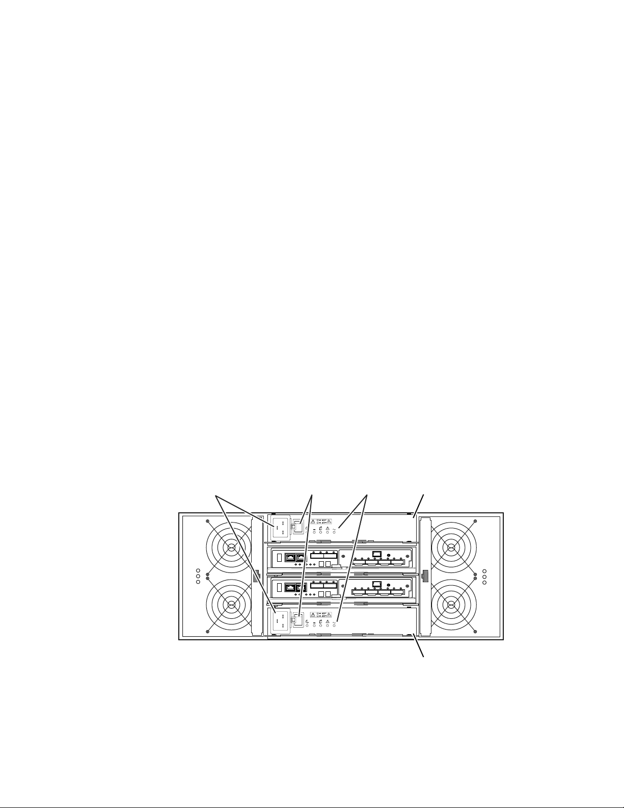
Attention:
– Repeatedly turning the power off and on without waiting for the drives to
spin down can damage the drives. Always wait for at least 90 seconds after
you turn off the power before you turn it on again.
– If you are connecting a power cord to a storage system enclosure, turn off the
power switches first. If the main circuit breaker is turned off, ensure that both
power switches are off on each storage enclosure in the rack before you turn
on the main circuit breakers.
– Turn on the power to the supporting devices (for example, Ethernet switches
and management stations) before powering on the storage system enclosures.
1. Check whether the main circuit breakers are turned on. If yes, then turn off both
power switches on each enclosure that you intend to connect to power. If not,
then turn off both power switches on all enclosures in the storage system.
2. Ensure that all power cords are connected.
Note: If the power cords are not connected, turn off both power switches on all
modules in the configuration before you connect power cords or turn on the
main circuit breakers.
3. If the main circuit breakers are turned off, turn them on.
Attention: You must turn on power to each attached expansion enclosure
before you turn on power to the controller enclosures so that the controllers
recognize all drives in the configuration during the startup process.
Depending on the number of enclosures in the configuration, the storage
system might take up to 10 minutes to fully power-on. While each storage
enclosure powers-on, the green and amber LEDs on the front and rear of the
storage enclosure turn on and off intermittently. The cache battery backup
self-test might take up to an additional 15 minutes to be completed. During this
time, the LEDs on the front and rear of the storage system might flash
intermittently.
4. Check the LEDs on the front and rear of all the storage enclosures. Ensure that
no amber LEDs are lit on any of the storage enclosures.
Power connector
Power switch LEDs
2
1
I
O
I
O
ACDC
2
1
ACDC
Power supply A
Power supply B
dcsi0056
Figure 25. Power-supply switches and connectors for DCS3860 dc models
5. Determine the status of all the components in the storage system configuration
by completing the following steps:
Chapter 4. Operating the DCS3860 storage system and EXP3800 expansion enclosure 57
Page 76

a. Check all LEDs on each component in the EXP3800 expansion enclosures.
Ensure that all the LEDs show normal status. For more information about
LED status for expansion enclosures, see “Checking the LEDs” on page 61.
b. Check all LEDs on each component in the DCS3860 storage system. Ensure
that all the LEDs show normal status. For information about LED status, see
“Checking the LEDs” on page 61 or “Solving problems” on page 123.
c. Open the Storage Manager Subsystem Management window, and display
the status of the storage system.
6. If the LEDs indicate normal operation and the Storage Manager GUI status is
'Optimal' on all the configuration components, then you have powered on the
DCS3860.
7. If the LEDs do not indicate normal operation or the Storage Manager GUI
status is not 'Optimal' on all the configuration components, then diagnose and
correct the fault by completing the following steps:
a. Run the Storage Manager Recovery Guru by clicking Recovery Guru in the
Subsystem Management window toolbar.
b. Complete the recovery procedure.
If the Recovery Guru directs you to replace a failed component, use the
individual LEDs on the storage system to locate the specific failed
component. For troubleshooting procedures, see “Solving problems” on
page 123.
c. When the recovery procedure is completed, select Recheck in the Recovery
Guru. This action runs the Recovery Guru again to make sure that the
problem is corrected.
d. If the problem remains, contact your IBM technical-support representative.
Installing the IBM DS Storage Manager
For instructions to install the DS Storage Manager software, see the IBM System
Storage DS Storage Manager Version 10.8 Installation and Host Support Guide for the
applicable operating system. The document is in the Documentation folder on the
IBM Support Software DVD. Use this document and the online help to configure the
arrays, logical drives, and host partitions for the controllers. Follow the instructions
in the operating-system documentation to make the new logical drives accessible to
the operating system. Do not proceed with the configuration setup until you have
completed the Storage Manager installation.
Assemble any additional items in preparation for software installation. These items
might include the following items:
v HBA device drivers
v Controller firmware
v IP addresses for controllers (for out-of-band management only)
v Additional documentation for hosts, HBAs, and other storage components
Save the storage system profile before any planned system shutdown or after any
system additions, removals, or modifications (including firmware updates, logical
drive creations, storage partitioning definitions, hardware changes, and so on). For
instructions to save the storage system profile, see the IBM System Storage DS
Storage Manager Version 10.8 Installation and Host Support Guide for the applicable
operating system. Save the profile in a location other than the logical drives that
are created for the storage system.
58 IBM System Storage DCS3860 Storage System: Installation, User's, and Maintenance Guide
Page 77

Ensure that you read the readme file that is included with the DCS3860 storage
system firmware package (whether the firmware is accessed by the Web or a DVD)
for any special requirements or restrictions that apply to that firmware version.
Note: Ensure that you install the Storage Manager event monitoring service to
enable continuous monitoring of the status of the storage system. For more
information about the importance of this information, see “Monitoring status
through software.”
Monitoring status through software
Run the software constantly, and check it frequently.
Note: You can monitor only storage systems that are within the management
domain of the Storage Manager. If you have not installed the Storage Manager
Event Monitor service as part of the storage-management software installation, the
Storage Manager Enterprise Management window must remain open. (If you close
the window, you will not receive any alert notifications from the managed storage
systems.)
For more information, see the Enterprise Management online help.
Important: For instructions to install the DS Storage Manager software, see the
IBM System Storage DS Storage Manager Version 10.8 Installation and Host Support
Guide for the applicable operating system. The document is in the Documentation
folder on the IBM Support Software DVD.
To download the latest version of the Storage Manager software, controller
firmware, NVSRAM firmware, and the latest ESM firmware, go to
http://www.ibm.com/servers/storage/support/disk/.
The Storage Manager software provides the best way to diagnose and repair
storage-system failures. The software can help you:
v Determine the nature of the failure
v Locate the failed component
v Determine the recovery procedures to repair the failure
Amber (needs attention) LEDs do not necessarily indicate which component has
failed or must be replaced or which type of recovery procedure you must perform.
In some cases (such as when a drive exceeds its Predictive Failure Analysis [PFA]
threshold), the amber LED is not lit. Only the Storage Manager software can detect
the failure.
For example, the recovery procedure for a PFA flag (impending drive failure) on a
drive varies depending on the drive status (hot spare, unassigned, RAID level,
current logical drive status, and so on). Depending on the circumstances, a PFA
flag on a drive can indicate a high risk of data loss (if the drive is in a RAID 0
volume) or a minimal risk (if the drive is unassigned). Only the Storage Manager
software can identify the risk level and provide the necessary recovery procedures.
Note: For PFA flags, the system-error LED and drive status LEDs are not lit, so
checking the LEDs will not notify you of the failure, even if the risk of data loss is
high.
Chapter 4. Operating the DCS3860 storage system and EXP3800 expansion enclosure 59
Page 78

Attention: Not following the software-recovery procedures can result in data loss.
In addition, always replace a failing component as soon as possible to minimize
additional failures that might occur and cause loss of data access.
Firmware updates
You must maintain the ESM firmware, controller firmware, drive firmware, and the
NVSRAM firmware up-to-date and know the prerequisites, update instructions,
download-sequence information, and host I/O restrictions.
Attention: Save the storage system profile before you perform any controller or
ESM firmware upgrades. Save the profile and all configuration (.cfg) files to a
server disk that will remain accessible in the event of a DCS3860 storage
configuration failure. Do not save these files only to a LUN in the storage system.
Go to http://www.ibm.com/servers/storage/support/disk/ to get the latest
updates.
Ensure that you read the readme files that are included with the firmware
packages for the most up-to-date information about firmware prerequisites,
firmware update instructions, download-sequence information, and host I/O
restrictions, if any. Apply the necessary updates before you configure the storage
system arrays and logical drives. Subscribe to My Support for automatic
notifications of firmware or Storage Manager software updates or any important
information about the DCS3860 storage systems (see “Receiving product updates
and support notifications” on page 5).
Attention: Failure to observe the limitations, prerequisites, sequences, and
dependencies in the readme file might result in a loss of data access.
Unless the readme file contains special requirements for the sequence in which you
upgrade firmware, perform firmware upgrades in the following sequence:
1. ESM firmware for the expansion enclosures
2. Controller firmware
3. Controller NVSRAM
4. Drive firmware
Troubleshooting the storage system
Run the IBM DS Storage Manager continuously, and frequently check the
configuration status.
IBM DS Storage Manager is the best way to monitor the storage system, diagnose a
problem, and recover from a hardware failure. Complete the following steps to
check the status of and identify a problem with the storage system. If a problem
has occurred, use the Storage Manager software and the LEDs on the storage
system to help locate a failed component.
1. Open the Subsystem Management window.
2. Click the Summary tab, and view the status of the storage system.
3. If any storage system has a 'Needs Attention' status, click Recovery Guru on
the toolbar. Perform the procedure in the Recovery Guru to correct the
problem. The Recovery Guru might direct you to replace the failed component.
If so, go to step 4 on page 61.
60 IBM System Storage DCS3860 Storage System: Installation, User's, and Maintenance Guide
Page 79
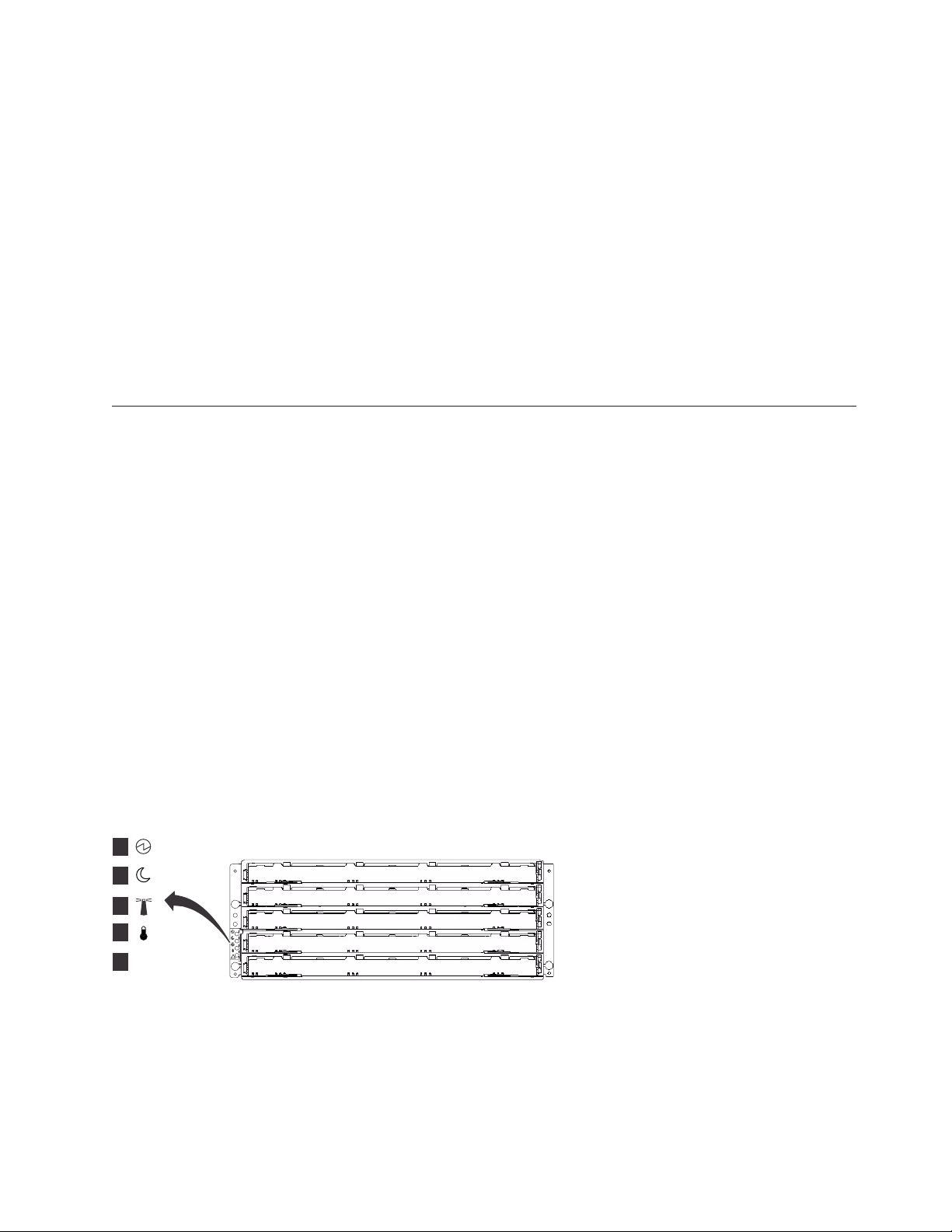
Attention: If the fault requires you to power-off an enclosure in your storage
system, you might have to cycle the power on the DCS3860 storage system and
all remaining expansion enclosures that are part of the storage system. Contact
your IBM technical-support representative before you power-off any other
component of the storage system.
4. If no storage system has a 'Needs Attention' status, then all components are
optimal. Check the LEDs on the front and the rear of the storage enclosure. A
green LED indicates a normal status; an amber LED indicates a hardware fault.
5. Check if the amber LED is lit. If yes, locate and troubleshoot the failed
components. See “Checking the LEDs.” If not, then you have completed this
procedure. If you are still experiencing a problem with the storage system,
create, save, and print a storage system profile, and contact your IBM
technical-support representative for assistance. When the recovery procedure is
completed, select Recheck in the Recovery Guru to run the Recovery Guru
again to make sure that the problem is corrected.
Checking the LEDs
The LEDs indicate the status of the storage system and components. Green LEDs
indicate a normal operating status; amber LEDs indicate a possible failure; a blue
LED on a component indicates that it is safe to remove the component.
The DCS3860 also has a blue system locator LED that is lit when the menu
function is selected in the Subsystem Management window, causing the Locate
command to be sent to the DCS3860.
Check all the LEDs on the front and rear of the storage system when you turn on
the power. During power-on, the LEDs flash intermittently as the storage system
and components complete the power-on process. In addition to checking for faults,
you can use the LEDs on the front of the storage system to determine whether the
drives are responding to I/O transmissions from the host.
Front LEDs
This section describes the primary LEDs and controls on the front of the DCS3860.
The front LEDs and controls for the DCS3860 storage system or expansion unit is
shown in Figure 26.
1
2
3
4
5
!
Figure 26. DCS3860 front LEDs and controls
!
dcsi0006
Figure 27. DCS3860 storage system and EXP3800 storage enclosure front LEDs
Chapter 4. Operating the DCS3860 storage system and EXP3800 expansion enclosure 61
Page 80

1 Power-on LED (green)
LED is lit, it indicates that the power supply is turned on and is supplying
both 5-volt and 12-volt dc power.
2 Standby power LED (green)
Future use only.
3 System locator LED (blue)
This blue LED can be lit by the Storage Manager software to aid in
visually locating the storage system.
4 Overtemperature LED (amber)
When this amber LED is lit, it indicates that the storage system is in an
over temperature condition.
5 System error LED (amber)
When this amber LED is lit, it indicates that the unit has a fault, such as in
a power supply, controller, or drive.
Controller LEDs
This section describes the controller LEDs on the rear of the storage system.
Ethernet activity LED
Ethernet speed LED
SAS link service
action LED (amber)
SAS link up LED
Cache active LED (green)
Fault LED (amber)
Service Action Allowed (blue)
Battery charging LED (green)
Battery fault LED (amber)
Figure 28. Controller LEDs
Ethernet speed LED
When this LED is lit, it indicates that the Ethernet speed between the
controller and the management workstation is 1000 Mbps. When this LED
is off, it indicates that the Ethernet speed is 100 Mbps.
Ethernet activity LED
When this LED is lit, it indicates that the link is established between the
controller and the management workstation. When this LED is flashing,
there is activity between the controller and the management workstation.
When this LED is off, no link is established between the controller and the
management workstation.
SAS link service action LED (amber)
When this LED is lit, it indicates a problem with the SAS link that requires
service action. The normal condition of this LED is off.
SAS link up LED (green)
When this LED is lit, it indicates that the link is established between the
controller and a host. When this LED is flashing, it indicates activity on the
link. When this LED is off, no link is established.
dcsi0047
62 IBM System Storage DCS3860 Storage System: Installation, User's, and Maintenance Guide
Page 81

Cache active LED (green)
When this LED is lit, it indicates that battery backup has been enabled and
data is in the memory cache. When this LED is flashing, cache offload is in
process. When this LED is off, caching is turned off and no data is in the
memory cache.
Fault LED (amber)
When this LED is lit, it indicates that a fault has occurred in the controller
and the controller must be replaced. The normal condition of this LED is
off.
Service Action Allowed LED (blue)
When this LED is lit, it indicates that it is safe to remove the controller
from the DCS3860; no activity is taking place, and no data remains in the
memory cache. The normal condition of this LED is off.
Battery charging LED (green)
When this LED is lit, the battery is fully charged. When this LED is
flashing, the battery is charging. When this LED is off, the battery either
failed or has been removed from the controller.
Battery fault LED (amber)
When this LED is lit, it indicates that the battery fails to hold a charge and
should be replaced. The normal condition of this LED is off.
Figure 29. SAS host port adapter LEDs
SAS link service action LED (amber)
SAS link up LED (green)
ESM LEDs
This section describes the ESM LEDS. Figure 30 on page 64 shows the LEDs on the
ESM.
SAS link service
action LED (amber)
SAS link up LED
dcsi0064
When this LED is lit, it indicates a problem with the SAS link that requires
service action. The normal condition of this LED is off.
When this LED is lit, it indicates that the link is established between the
controller and a host. When this LED is flashing, it indicates activity on the
link. When this LED is off, no link is established.
Chapter 4. Operating the DCS3860 storage system and EXP3800 expansion enclosure 63
Page 82

ESM
Link fault LED
(amber)
1 2
Link up LED
(green)
Link fault LED
(amber)
Link up LED
(green)
Service Action Allowed
(blue)
Fault LED
(amber)
Figure 30. ESM LEDs
Fan assembly LEDs
Power-on LED
(green)
Seven-segment
numeric display
dcsi0062
Link fault LED (amber)
When this amber LED is lit, it indicates that the link through the SAS cable
is not successful.
Link up LED (green)
When this green LED is lit, it indicates that the link through the SAS cable
is successful.
Service Action Allowed (blue)
This LED is supported only when the EXP3800 is attached to a DCS3860
controller. Do not remove the ESM unless this blue LED is lit.
Fault LED (amber)
When this amber LED is lit, it indicates that the ESM has failed.
Power-on LED (green)
When this green LED is lit, it indicates that the ESM is receiving power.
This section describes the storage expansion enclosure fan assembly LEDs.
1
2
3
dcsi0007
Figure 31. Fan assembly LEDs
64 IBM System Storage DCS3860 Storage System: Installation, User's, and Maintenance Guide
Page 83

Table 15. Fan assembly LEDs
Number LED Normal Status Problem Status
1
Power
®
On (Green) Off: No power to fan
assembly
2
Service Action Required
(Fault)
3
Service Action Allowed
AC power-supply LEDs
This section describes the primary LEDs on the DCS3860 ac power supplies.
2
I
O
Figure 32. AC power-supply LEDs
1 Standby power LED (green)
Future use only.
1
1
2
Off On (Amber): A fault exists
within the fan assembly
Off On (Blue): The fan
assembly can be removed
ACDC
3
5
4
dcs00010
2 DC power LED (green)
When this green LED is lit, it indicates that the DCS3860 is turned on and
is supplying 5-volt, 12-volt, and 48-volt dc power.
3 Service Action Allowed LED (blue)
When this blue LED is lit, it indicates that it is safe to remove the power
supply.
4 Fault LED (amber)
When this amber LED is lit, it indicates that a power supply or fan has
failed or that a redundant power supply is not turned on.
5 AC power LED (green)
When this green LED is lit, it indicates that the storage system is receiving
ac power.
Drive drawer LEDs
This section describes the LEDs on storage expansion enclosure drive drawers.
Chapter 4. Operating the DCS3860 storage system and EXP3800 expansion enclosure 65
Page 84

Drive drawer levers
3
2
1
Figure 33. Drive drawer LEDs
Table 16. Drive drawer LEDs
Number LED Normal Status Problem Status
1
2
Service Action Allowed
Service Action Required
(Fault)
5
4
OK
6
8
7
Off On (Blue): The drive
Off On (Amber): A fault exists
9
10
11
drawer can be removed
The drawer Service
Action Allowed LED is
also lit when a Service
Action Allowed LED on
one of the drives in the
drawer is lit.
within the drive drawer
12
13
14
dcsi0008
3-14
Drive Activity (for drives
1 to 12 in the drawer)
Note: The associated disk
drive is indicated by a
number (1 to 12) that is
displayed inside the Drive
Activity icon.
Disk drive LEDs
This section describes the service LEDs on the disk drives.
The drive power/drive activity LEDs are located on the front of the drive drawer.
See “Drive drawer LEDs” on page 65 for more information.
On (Green): Power is on,
drive is operating
normally
Flashing (Green):
Indicates drive I/O
activity
Off: No power to the
drive or a drive is not
installed
66 IBM System Storage DCS3860 Storage System: Installation, User's, and Maintenance Guide
Page 85

Figure 34. Disk drive LEDs
Table 17. Disk drive LEDs
Number LED Normal Status Problem Status
1
Service Action Allowed
Off On (Blue): The disk drive
can be removed
2
Service Action Required
(Fault)
Off On (Amber): A fault exists
within the disk drive
Table 18. Drive state indicated by the LEDs
Drive State
Drive Power LED
(Green)
Drive Service
Action Required
LED (Amber)
Drive Service
Action Allowed
LED (Blue)
Power is not applied Off Off Off
Normal operation: The
On Off Off
power is turned on but
there is no drive I/O
activity
Normal operation: Drive
flashing Off Off
I/O activity is occurring
Service Action Required: A
On On On
fault condition exists and
the drive is offline
Power is applied but
drives are spun-down
because they are offline,
are part of an "Exported Ready to import" array, or
are incompatible or not
certified.
Chapter 4. Operating the DCS3860 storage system and EXP3800 expansion enclosure 67
Off Off On
Page 86

Seven-segment numeric display LEDs
The seven-segment numeric display LEDs provide information about enclosure
identification and diagnostics. Figure 35 shows the numeric display LEDs and the
heartbeat and diagnostic LEDs.
Diagnostic Light
A
SSD 1
F
Heartbeat Light
Figure 35. Numeric display LEDs
B
G
CE
D
DP
DP
C
D
SSD 2
G
A
E
Lower DigitUpper Digit
FB
dcsi0038
When you turn on the power to the storage or storage enclosure, the numeric
display LEDs cycle through various codes as the controller or ESM firmware starts
to boot. If the diagnostic LED is illuminated and the heartbeat LED is turned off, it
indicates that diagnostic information is displayed on the numeric display. When
the controller completes the boot process and is operating normally, the diagnostic
LED turns off, the heartbeat LED flashs, and the numeric display changes to show
the enclosure identification (enclosure ID) for that individual enclosure.
If an error occurs during the boot process and the Needs Attention LED is on, the
numeric display shows diagnostic information as sequence of 2-digit diagnostic
code. The number of time each 2-digit code is displayed during a sequence is fixed
and under hardware control. Each sequence minimally consists of a two-digit
category code, followed by a two-digit detail code that is specific to the category.
Longer sequences can be displayed if more than one event is to be reported. This
nominally consists of a series of category-detail sequences with a delimiter
between each category-detail sequence. The entire display goes blank at the end of
the sequence (all segments off, the diagnostic light off), and then the sequence
repeats.
For more information about the diagnostic codes and their possible causes, see the
"Seven-segment display sequence codes and their causes" section of this document.
Cache memory and cache battery
Cache memory size stores read and write operations in the DCS3860 system. Each
storage controller in the DCS3860 storage system contains 12 GB of cache memory
to store read and write operations. In a dual controller configuration, both
controllers in the DCS3860 must have the same amount of cache memory. The
battery unit contains enough charge to back up the cached data in each controller
to a flash drive in the event of a DCS3860 power failure.
68 IBM System Storage DCS3860 Storage System: Installation, User's, and Maintenance Guide
Page 87

Cache memory
The controller has a cache active LED that indicates the current status of the cache.
The LED is lit when there is data in the cache, and it is off when there is no data
in the cache.
If caching is enabled and the cache active LED is not lit during I/O, it indicates
one of the following conditions:
v The cache memory from either controller A or controller B has failed.
v The cache sizes in controller A and controller B are not the same.
v The battery has failed.
Note: Always use the Storage Manager client to check the cache memory settings
before you assume that a hardware device has failed.
See“Controller LEDs” on page 62 for the location of the cache active LED on a
controller.
Controller cache battery
The backup battery unit provides power to back up the cache memory of each
controller onto flash drives in the event of a power failure. Each battery unit
contains a sealed, rechargeable SMART lithium ion battery.
CAUTION:
The battery is a lithium ion battery. To avoid possible explosion, do not burn.
Exchange only with the IBM-approved part. Recycle or discard the battery as
instructed by local regulations. In the United States, IBM has a process for the
collection of this battery. For information, call 1-800-426-4333. Have the IBM part
number for the battery unit available when you call. (C007)
Replace the battery units in the DCS3860 storage system if they are identified as
failing by the Subsystem Management window, or when the battery fault LEDs are
lit. See “Controller LEDs” on page 62 for the location of the battery fault LED.
Replace only the battery unit that is indicated as failed by the LEDs or in the
Subsystem Management window. In a dual controller configuration, you do not
have to replace both battery units when the Battery fault LEDs indicate that only
one battery unit has failed. Each controller has a green Battery charging LED that
indicates the status of the battery unit.
v The LED is on when the battery is fully charged.
v The LED flashes when the battery is charging or performing a self-test.
v The LED is off when the battery or the battery charger has failed or is missing.
Cache battery learn cycle
The battery performs a learn cycle the first time the storage system is turned on,
and again every eight weeks thereafter, to assess the charge capacity of the battery.
If the battery fails the learn cycle or takes too much time to reach full charge, the
Battery charging LED turns off, the Battery fault LED turns on and the Storage
Manager identifies the battery as failed.
Chapter 4. Operating the DCS3860 storage system and EXP3800 expansion enclosure 69
Page 88

The learn cycle takes up to three hours. During this time, the cache will be active if
the battery is in optimal condition. If the learn cycle is interrupted, the current
learn cycle will be terminated and the battery will perform a new learn cycle at the
next scheduled interval (eight weeks from the current learn cycle). A learn cycle
interruption is caused by removing the battery from the controller chassis, resetting
the power to the storage system, or if an storage enclosure or battery overheats.
Data caching starts after the battery is charged to the programmed voltage level,
which occurs when the storage system power is first turned on, when a new
battery is installed to replace a failed battery, or when the system power is turned
on after months of inactivity.
Attention: Write caching is suspended while a battery pack is either charging or
self-testing.
Turning off the storage system
The DCS3860 is designed to run continuously. After you turn it on, do not turn it
off. Turn off the power only in the following situations:
v Instructions in a hardware or software procedure require that you turn off the
power.
v An IBM technical-support representative instructs you to turn off the power.
v A power outage or emergency situation occurs, see “Restoring power after an
unexpected shutdown” on page 73 .
Attention: Except in an emergency, never turn off the power if any amber (needs
attention) LEDs are lit. Correct the fault before you turn off the power. Use the
Storage Manager software and the amber LEDs to check the overall status of the
DCS3860 . All LEDs should be green on the front of the storage system. If they are
not, use the Storage Manager software to diagnose the problem so that the
DCS3860 will power-on correctly later.
(L003)
1
2
or
70 IBM System Storage DCS3860 Storage System: Installation, User's, and Maintenance Guide
Page 89

!
1
2
Attention:: Turning off and turning on power without waiting for the storage
system disk drives to spin down can damage the drives and might cause data loss.
Always wait at least 90 seconds after you turn off the power before you turn on
the power again.
Power-off overview
Turn off the power to each device according to the following shutdown sequence:
1. Turn off power to the host before the storage system. If the host must stay
powered-on to support a network, see the operating-system documentation for
information about disconnecting the storage system logical drives from the host
before the storage system is powered-off.
2. Turn off power to the storage system before you turn off power to the
expansion enclosures. Turn off both power-supply switches on the rear of the
enclosures.
3. Turn off power to other supporting devices (for example, management
stations).
Note: You do not have to perform this step if you are servicing only the
storage system.
To turn off power to one or more components of the storage system for a planned
shutdown, complete the steps in the following procedure. To turn off power for an
unplanned shutdown, see“Restoring power after an unexpected shutdown” on
page 73.
Figure 8 on page 14 shows the locations of the power switches on a storage system.
Before you proceed, use the Storage Manager software to determine the status of
the storage system components and special instructions. You might have to
complete other procedures before you turn off the power.
Chapter 4. Operating the DCS3860 storage system and EXP3800 expansion enclosure 71
Page 90

1. Stop all I/O activity to each storage system.
2. Determine the status of all storage systems components in the configuration by
completing the following steps:
a. Check all LEDs on each component in the expansion enclosures. Ensure that
all the LEDs show normal status.
b. Check all LEDs on each component in the storage system. Ensure that all
the LEDs show normal status.
c. Review the status of the configuration in the Subsystem Management
window by clicking the Summary tab.
The status is either Optimal or Needs Attention.
3. If the LEDs do not indicate normal operation or the status on all configuration
components is not 'Optimal', diagnose and correct the fault:
a. Run the Recovery Guru by clicking Recovery Guru in the toolbar of the
Subsystem Management window.
b. If you need to replace a failed component, use the individual LEDs to locate
the failed component.
c. When the recovery procedure is completed, click Recheck in the Recovery
Guru. This action runs the Recovery Guru again to ensure that the problem
is corrected.
d. If the problem has not been corrected, contact your IBM technical-support
representative. Do not turn off power until all problems are corrected.
4. If the LEDs indicate normal operation and the status on all configuration
components is 'Optimal', check the cache active LED, and ensure that it is off.
If the cache active LED is lit, the cache contains data. Wait for the data to clear
from cache memory before you turn off the power.
5. Check the LEDs of the disk drive drawer to ensure that all drive activity LEDs
are off.
If one or more LEDs are flashing, it indicates that data is being written to or
from the drives. Wait for all activity LEDs to stop flashing.
6. Turn off the ac power switch on the rear of the DCS3860 storage system in the
storage system.
Note: Until the power switch on each power supply is turned off, power
remains turned on for both controllers.
7. Turn off both power switches on the rear of each storage expansion enclosure
in the configuration.
8. After you perform the necessary maintenance procedures, turn on the power,
using the procedure in “Powering on the DCS3860” on page 56.
Performing an emergency shutdown
Emergency situations might include fire, flood, extreme weather conditions, or
other hazardous circumstances. If a power outage or emergency situation occurs,
turn off all power switches on all computing equipment. This helps to safeguard
your equipment from potential damage due to electrical surges when power is
restored. If the storage system loses power unexpectedly, it might be due to a
hardware failure in the power system or in the midplane.
Complete the following steps to shut down the system during an emergency:
1. If you have time, stop all I/O activity to the storage system by shutting down
the host or disconnecting the storage system logical drives through the host.
72 IBM System Storage DCS3860 Storage System: Installation, User's, and Maintenance Guide
Page 91

2. Check the LEDs. Note down any amber LEDs that are lit so that you can
correct the problem when you turn on the power again.
3. Turn off all power-supply switches, starting with the DCS3860 storage system
first and followed by the EXP3800 expansion enclosures. Then, disconnect the
power cables from the storage system.
Restoring power after an unexpected shutdown
Complete the following steps to restore power to the storage system after an
unplanned shutdown:
DANGER
Never turn on any equipment when there is evidence of fire, water, or
structural damage.
1. After the emergency situation is over or power is restored, check the storage
system for damage.
2. If there is evidence of damage to any of the storage system components, cables,
or equipment that is attached to the storage system, do not continue with this
procedure. Contact your IBM technical-support representative for assistance.
Depending on the current service agreements, you might have to return the
equipment to the factory or local service center for repair.
Attention: To avoid potential data loss, ensure that the storage system and the
expansion enclosure power switches are turned off before you reset circuit
breakers in the rack. Resetting circuit breakers after an emergency situation
while the storage system and the expansion enclosure power switches are
turned on can cause data loss, because the configuration components might not
be powered-on in the correct sequence. See “Powering on the DCS3860” on
page 56 for details about the correct power-on sequence.
3. After you check the storage system for damage, ensure that the power switches
are off; then connect the DCS3860 power cables, if required.
4. Check the system documentation of the hardware devices that you want to
turn on and determine the correct startup sequence.
5. Turn on both of the power-supply switches on EXP3800 expansion enclosures
and make sure that no ESM or power-supply fault LEDs are lit before you
power on the DCS3860 storage system.
In addition, consider the following items:
v The storage system supports simultaneous power-on of the system
components. However, always check the system documentation of the
hardware devices that you want to turn on and determine the correct startup
sequence.
v A storage system in an optimal state recovers automatically from an
unexpected shutdown and unattended simultaneous restoration of power to
system components. After power is restored, contact your IBM
technical-support representative if any of the following conditions occur:
– The storage system logical drives and arrays do not display in the Storage
Manager graphical user interface.
– The storage system logical drives and arrays do not come online.
– The storage system logical drives and arrays seem to be degraded.
6. Turn on both of the power-supply switches on the DCS3860 storage system. See
“Solving problems” on page 123.
Chapter 4. Operating the DCS3860 storage system and EXP3800 expansion enclosure 73
Page 92

Recovering from an overheated power supply
Each storage enclosure contains two power supplies. Each power supply contains a
built-in temperature sensor to prevent the power supply from overheating. Under
normal operating conditions, with an ambient air temperature range of 10°C to
40°C (50°F to 104°F), the fans in the power supplies maintain a suitable operating
temperature inside the module.
If the internal temperature reaches 65°C (149°F), the power supply shuts down
automatically. If both power supplies shut down because of overheating, the
storage system has no power, and all LEDs are off.
The following factors can cause the power supplies to overheat:
v An unusually high room temperature
v Fan failures in the power supplies
v Defective circuitry in a power supply
v Blocked air vents
v Failures in other devices in the configuration or rack
If a fan failure causes overheating, the system-error LED and overtemperature
LEDs on the front bezel are lit. The fault LED on the power supply might also be
lit.“Checking the LEDs” on page 61 shows the location of the LEDs on the
DCS3860.
If the storage system temperature exceeds 45°C (113°F), the IBM DS Storage
Manager displays a Needs Attention icon in the Subsystem Management window.
If the air temperature inside the rack reaches 65°C (149°F), the power supplies
automatically shut down. If event monitoring is enabled and event notification is
configured, the software issues two critical-problem notifications.
v If one power supply shuts down, the storage management software displays a
Needs Attention status in the Subsystem Management window.
v If both power supplies shut down, the storage system shuts down, and the
storage management software displays a Not Responding status in the
Subsystem Management window.
Attention: To prevent damage to the storage system components when the
power supplies automatically shut down, immediately remove all rack panels to
help reduce the rack air temperature.
Complete the following steps to resume normal operation after a power-supply
shutdown:
1. Confirm whether you used the procedure in “Troubleshooting the storage
system” on page 60 to ensure that the power supplies have shut down
because of an overheating problem.
2. Stop I/O activity to the storage system and all attached expansion enclosures.
3. Take all or some of the following measures to alleviate the overheating
problem:
v Remove all panels from the rack immediately.
v Use external fans to cool the area.
v Shut down the power to the storage enclosure, using the procedure that is
described in “Performing an emergency shutdown” on page 72.
4. Wait for the air in and around the storage system to cool.
74 IBM System Storage DCS3860 Storage System: Installation, User's, and Maintenance Guide
Page 93

After the temperature inside the power supplies drops to below 65°C (149°F),
the storage system is capable of power-on recovery without operator
intervention. After the air has cooled, the power supplies should turn on
automatically. If the power supplies restart automatically, the controllers will
reset and return to normal operation.
5. If the power supplies restarted automatically, go to step 8.
6. If the power supplies did not restart automatically, turn off both power
switches on the DCS3860 storage system (see Figure 8 on page 14 and then
power-off all connected EXP3800 expansion enclosures. Wait for a minute and
then turn on power to all connected EXP3800 expansion enclosures.
While the expansion enclosure powers on, the LEDs on the front and the rear
of the enclosure flash intermittently. Depending on the configuration, the
expansion enclosure can take between 20 seconds and several minutes to
power on.
7. Turn on both power switches on the rear of the DCS3860 storage system.
The storage system can take up to 10 minutes to power on and up to 15
minutes for the battery self-test to be completed. During this time, the LEDs
on the front and the rear of the storage system flash intermittently.
8. Check the LEDs on the front and rear of the storage system and each attached
expansion enclosure (a green LED indicates a normal status; an amber LED
indicates a hardware fault); then, check the array status in the Subsystem
Management window.
v Open the Subsystem Management window for the storage system.
v Click the Summary tab and review the status of the configuration.
The status is either Optimal or Needs Attention.
9. If any module (controller, power supply, ESM) does not display a green status
LED, or if the status for any module component is not 'Optimal', diagnose and
correct the fault.
a. To run the Recovery Guru, click Recovery Guru in the toolbar in the
Subsystem Management window.
b. If you need to replace a failed component, locate and troubleshoot that
component. See “Checking the LEDs” on page 61.
c. When the procedure is completed, select Recheck in the Recovery Guru.
This runs the Recovery Guru again to ensure that the problem is corrected.
d. If the problem remains, contact your IBM technical-support representative.
10. Replace the bezel on the storage enclosure, if applicable.
Chapter 4. Operating the DCS3860 storage system and EXP3800 expansion enclosure 75
Page 94

76 IBM System Storage DCS3860 Storage System: Installation, User's, and Maintenance Guide
Page 95

Chapter 5. Replacing components
Replacing components
This section contains information about replacing components or installing optional
devices in the DCS3860 storage system and EXP3800 expansion unit.
Before you replace any component, ensure that you wear an anti-static wrist strap.
Attention: To avoid overheating the storage enclosure and causing damage to its
components, replace failed parts within 10 minutes, unless otherwise indicated.
The Recovery Guru in the Storage Manager software identifies failed parts.
Do not remove the failed part from the storage enclosure until you:
v Review the replacement procedure for the failed part in this guide.
v Locate screw drivers or any other hand tools that you might need to replace the
failed part.
v Receive the replacement part and are ready to install it in the enclosure.
Service Action Allowed LED
Each controller, ESM, fan assembly, disk drive, disk drive drawer, and power
supply has a blue Service Action Allowed LED. This LED helps ensure that a
component is not removed before it is safe to do so. Do not remove any
component unless the component Service Action Allowed LED is lit.
Attention
If you remove a controller, ESM, disk drive, disk drive drawer, or power supply
when the Service Action Allowed LED is not lit, it might result in data
unavailability. If an amber LED is lit and the associated Service Action Allowed
LED is not lit, you must run additional diagnostics before you can remove the
indicated component. Use the Recovery Guru instructions in the Subsystem
Management window or see the applicable component replacement instructions in
this chapter for the additional diagnostics that are required in this case.
The Service Action Allowed LED automatically turns on or off as conditions
change. Wait for at least two minutes after you replace a component for the storage
system to recognize the new component and update the LED status. In most cases,
when a single component fails, the Service Action Allowed LED stays lit when the
amber LED is lit for the component.
Working with controllers
This section describes how to remove a controller, remove and install a cover,
install a controller, replace a controller, and dispose of the system-board battery on
the controller.
Before you begin, ensure that you wear an anti-static wrist strap.
© Copyright IBM Corp. 2013 77
Page 96

CAUTION:
To prevent damage from overheating, replace a failed controller assembly FRU
within 5 minutes of removal. If replacing it will take longer than 5 minutes,
then ensure that the temporary filler that is shipped with the controller
assembly FRU is installed in the SBB slot until you complete the replacement.
Do not remove the failed part from the storage enclosure until you:
v Review the replacement procedure for the failed part in this guide.
v Locate screw drivers or any other hand tools that you might need to replace the
failed part.
v Receive the replacement part and are ready to install it in the enclosure.
Removing a controller
Before you begin:
v Read the "Safety" and "Best practices guidelines" sections of this document.
v Ensure that you wear an anti-static wrist strap.
Attention: Never remove a controller unless the Service Action Allowed LED is
lit. Doing so can result in loss of data.
Complete the following steps to remove a controller from the storage system:
CAUTION:
To prevent damage from overheating, replace a failed controller assembly FRU
within 5 minutes of removal. If replacing it will take longer than 5 minutes, stop
all I/O activity to the storage expansion enclosure and turn off the power until
you complete the replacement.
1. If the controller has failed, do not continue with this procedure. Instead, go to
“Replacing a controller” on page 80.
Attention: Handle and install cables correctly to avoid degraded performance
or loss of communication with devices. See Chapter 3 "Cabling the DCS3860" in
this document for more information.
2. Disconnect all interface cables from the controller. Ensure that you label each
cable so that you can reconnect it correctly.
3. Remove the controller from the chassis.
78 IBM System Storage DCS3860 Storage System: Installation, User's, and Maintenance Guide
Page 97

I
O
2
1
DC
A
C
Port 1
Port 2
ID/
Diag
H
o
s
t
1
C
a
r
d
Release
levers
Figure 36. Removing a controller
a. Hold the release lever with orange attachment and open it. Both the release
levers open. The controller moves out of the bay approximately 1 cm (0.4
inch).
b. Hold both the release levers and pull the controller out of the enclosure.
c. Place the controller on a level surface.
dcsi0059
Attention: After you remove a controller, wait for 90 seconds before you reseat or
replace the controller. Failure to do so might cause unpredictable results.
Removing and installing a cover
Before you begin:
v Read the "Safety" and "Best practices guidelines" sections of this document.
v Ensure that you wear an anti-static wrist strap.
Complete the following steps to remove a cover from a controller:
1. Press the two release buttons and slide the cover toward the rear of the
controller.
Chapter 5. Replacing components 79
Page 98

Figure 37. Removing the cover
2. Remove the cover and save it for future use.
To install a cover on a controller, align the cover on the controller and slide it
toward the front of the controller.
Replacing a controller
Before you replace a controller in a DCS3860 storage system:
v Ensure that both power supplies are connected and powered-on and no amber
LEDs are lit. Ensure that the power LEDs on both power supplies are lit. If the
status of either of the power supplies is not Optimal, replace that power supply
before you proceed with the controller replacement procedure.
v If you are replacing a failed controller with a replacement controller from IBM
Service, ensure that you have ordered the replacement controller that contains
the same amount of cache memory that is installed in the failed controller. Also,
transfer the cache backup battery to the replacement controller. Transfer the
battery exactly as described in this procedure. If you do not remove and insert
the battery in the correct sequence, you could damage the controller.
v Read the "Safety" and "Best practices guidelines" sections of this document.
v Check the WWIDs or the MAC addresses of the host ports after replacing the
controller or the host port interface adapter, or both. If you need to change any
WWID or MAC address, update the servers or switches in the configuration.
v Ensure that you wear an anti-static wrist strap.
Release
buttons
dcsi0048
Note: While replacing the controller in a DCS3860 storage system , you may
require an additional controller air diverter.
To replace a controller in a DCS3860 storage system:
80 IBM System Storage DCS3860 Storage System: Installation, User's, and Maintenance Guide
Page 99

CAUTION:
To avoid overheating the storage enclosure and causing damage to its
components, replace failed parts within 10 minutes unless directed otherwise.
The Recovery Guru in the Storage Manager software identifies failed parts.
1. Use the Storage Manager software to print a storage system profile.
2. Move logical drive ownership to the other controller. If the controller that you
are replacing has failed but is still operating, move the failed controller to the
Offline state.
Attention: Never remove a controller unless the Service Action Allowed LED
is lit. Doing so can result in a loss of data.
3. Locate the failed controller by checking the amber LEDs on the controllers in
the storage system.
4. If the Service Action Allowed LED is not lit, another component might require
attention before you remove the controller. Use the Recovery Guru in the
Subsystem Management window to identify and correct any additional
failures. If there are none, proceed with step 5 to replace the controller.
Attention: Static electricity can damage the storage system and other
electronic devices. To avoid damage, keep static-sensitive devices in their
static-protective packages until you are ready to install them.
5. Unpack the new controller. Save all packing materials in case you have to
return the new controller.
6. Determine whether the replacement controller will be controller A or
controller B (controller A is installed in slot A; controller B is installed in slot
B), and then paste the controller labels for host ports and drive expansion
ports to the replacement controller. The controller labels and instructions are
included with the replacement controller. Ensure that the labels are aligned
correctly and do not cover any connectors or LEDs.
Attention: Handle and install cables correctly to avoid degraded
performance or loss of communication with devices. See Chapter 3 "Cabling
the DCS3860" for more information.
7. Disconnect all attached interface cables from the failed controller. Be sure to
label each cable so that you can reconnect it correctly to the new controller.
8. Remove the controller from the chassis
Chapter 5. Replacing components 81
Page 100

I
O
2
1
D
C
A
C
P
ort 1
Port 2
ID/
Diag
H
o
s
t
C
1
a
r
d
Release
levers
Figure 38. Removing and replacing a controller
a. Hold the release lever with orange attachment and open it. Both the
release levers open. The controller moves out of the bay approximately 1
cm (0.4 inch).
b. Hold both the release levers and pull the controller out of the enclosure.
c. Place the controller on a level surface.
dcsi0059
Attention: The DCS3860 replacement controller ships with a temporary
filler. Place the temporary filler in the controller chassis bay after the failed
controller is removed, to maintain proper airflow and cooling.
9. Remove the cover (see “Removing and installing a cover” on page 79).
10. Remove the host interface card and set it aside (see “Replacing a host interface
adapter” on page 85).
11. Remove the battery from the failed controller (see “Replacing a memory cache
battery” on page 103).
82 IBM System Storage DCS3860 Storage System: Installation, User's, and Maintenance Guide
 Loading...