

Page 1
Hard ware Main tenance Service
for Service Level A
Machine Types 2170, 2171 and 2172 and
IBM Monitors 2235, 2236 and 2237
2170/2171/2172 2235/2236/2237
Page 2

Second Edition (March, 2000)
The following paragraph does not apply to any state or country where such
provisions are i nconsistent with local law: I NTERNATIONA L BUSINESS
MACHINES CORPORATION PROVIDES THIS PUB L ICATION “AS IS”
WITHOUT WARRANTY OF ANY KIND, EITHER EXPRESSED OR IMPLIED,
INCLUDING, BUT NOT LIMITED TO, THE IMPLIED WARRANTIES OF
MERCHANTABILITY OR FITN E S S FOR A PARTICULAR PURPOSE.
References to IBM products, programs, or services do not imply that IBM
intends to mak e them availab le outside t h e Uni ted Sta t es. T his pu blication
could include tech ni cal ina c curacies or typographic al e r rors. Changes are
periodically made to the information herein; these changes will be made in later
editions. IBM may make improvements and/or changes in the product(s) and/
or the program(s) at any time. Address comments about this publication to IBM
Corporation, Dept. E23/962-2, 455 Park Place, Lexington, KY 40511-1856,
USA. Information you su pply may be used by IBM without obligation. For
copies of publications r ela t ed to this product, call toll free 1 -800-IBM-7282 in
the Continenta l U.S.A. In Canada, call toll free 1-800-465-7999.
© Copyright International Business Machines Corporation 2000.
All rights reserved.
Note to U. S . Gover nm ent Users - Doc um e nta tion related to restricted ri ghts Use, duplication or disclosure is subject to restrictions set fo r th in GSA ADP
Schedule Contract with IBM Corp.
Page 3

Contents
Contents ..........................................................................................................I
Notices ...... ...................... ...................... .................... ................................... V II
Safety Information ........................................................................................VIII
Laser Compliance Statement ............................................... .. .....................XXX
Trademarks .......... .................... ...................... .................... ........................XXXI
Preface ....... .... ...... ...... .... ...... ...... .... ...... ...... .... ...... ...... .... ...... .....................XXXII
General Inf or mation ..... .... .. .... .. .... .. .... .. .... .. .... .... .. .... .. .... .. .... .. .... .. ..................1
Introduction ......................................................................................................2
Product Overview ........ .............................. ................ .......................................3
Processors (Machine Type 2170) ...... .. .. .. .. .. .. .. .. .. .. .. .. .. .. .. .. .. .. .. .. .. .. ...........3
Processors (Machine Type 2171/2172) .... .. .. .. .. .. .. .. .. .. .. .. .. .. .. .. .. .. .. .. ..........3
Memory ..................................................................................................... 4
External Ports............................ ................ ................ ................................ 4
Diskette Drive ......... .... .... .. .... .... .... .... .... .... .... .... .... .... .... .. .... .... ...................4
Hard Disk Drive ..... ........ ...... ........ ........ ...... ........ ........ ...... ........ ..................5
CD/DVD-ROM Drive .................................................................................5
Multimedia .......... .................. .................. .................. .................................5
Video Cards ....................... .. .. .. .. .. .. .. .. .. .. .. .. .. .. .. .. .. .. .. .. .. .. .. .. .. .. .. .................5
Power Management ..................................................................................5
Power Supply ............................................................................................6
Internal Cabling ............. .. ................ ................ ................ ..........................6
Monitor (Not includ ed with some models) .. .. .... .. .. .. .... .. .. .. .... .. .. .. .... .. .........6
Keyboard ....... .................. ................ ................ .................. ........................7
Mouse .......................................................................................................7
Hardware Interfaces .........................................................................................8
CMOS Reset .... .. .. ................ ................ ................ ................ ..........................10
Power-On P a s s word ................ .. .. .. .. .. .. .. .. .. .. .. .. .. .. .. .. .. .. .. .. .. .. .. .. .. .. .. ................11
Flash (BIOS) U pdat e Procedure ................... .... .. .... .. .... .. .... .... .. .... .. ............... 12
BIOS-contained Mod el Number and Serial Number . .. .. .... .. .. .. .. .... .. .. .. .. .. .......13
BIOS Setup Utility ............................... ................ ................ ...........................14
Working with the Setup Menus ...............................................................14
Viewing System Information,Video Information and
Model Information ...................... .. .. .. .. .. .. .. .. .. .. .. .. .... .. .. .. .. .. .. .. .. .. ...............16
Disk Drives ................. .. ................ ................ ................ ...........................17
Input/Output Ports ................ .. .... .... .. .... .. .... .... .. .... .. .... .... .. .... .. .................19
Power Management ................................................................................20
Startup Opti ons ................... .............................. ......................................21
Date and Time ...................... ........ ........ ........ ...... ........ ........ .....................21
Contents I
Page 4

Advanced Options ................ .............................. ................ .....................22
Specifications ... .................. ................ .................. ................ ..........................27
Dimension ( wi dth x dep th x he ight) ................ .. .. .. .. .. .. .. .. .. .. .. .. .. .. .. ...........27
Weight .......... .......................... .......................... .......................................27
Environment ..... .......................... .......................... .......... .........................27
Power consumption .................................................................................28
Electrical input .........................................................................................28
Operating Requi rements ................. .. .. .. .. .. .. .. .. .. .. .. .. .. .. .. .. .. .. .. .. .. .. .. .. ...............2 9
Special Tools ................................... .. .. ................ .. .. .. ................ .. ..................30
Check Procedures ................. .. .... .. .. .... .. .... .. .. .... .. .... .. .... .. .. .... .. .... ................31
Introduction ....................................................................................................32
Start ...............................................................................................................33
Index of Symptoms, Messages, Error Codes, or Beeps ...... .................. .. ......37
Troubleshooting .............................................................................................53
Factory-Insta lle d Storag e Devices ....... .. .... .... .. .... .... .. .... .... .. .... .... ........... 5 3
Factory-Installed Modem Card .......................................................................56
Audio (Not S up ported by Diagnostics Program) ................ .. .. .. .. .. .. .. .. .. .. ........58
CD/DVD-ROM Drive ......................................................................................60
Memory ........ ........................ ...................... ...................... ..............................61
Keyboard . ................ .............................................. .........................................62
Mouse ............................................................................................................63
Power Supply .................................................................................................65
Monitor ..... .......................... ........................ ........................ ............................68
Undetermined Problems ..................... .. .. .. .. .. .... .. .. .. .. .. .. .. .. .. .. .. .. .. .. .. ...............70
Diagnostic Aids ............................................................................................73
Introduction ....................................................................................................74
Power-On S e lf T e s t .......... .. .. .. .. .. .. .. .. .. .. .. .. .. .. .. .. .. .. .. .. .. .. .. .. .. .. .. .. .. .. .. ................75
Diagnostic Dis ket te ............ .... .... .. .... .... .... .... .... .. .... .... .... .... .. .... .... ..................76
Using the Di agnos tic Diskette ......... .. .... .... .. .... .... .. .... .... .. .... .... .. .............. 7 6
Using Diagnosti c Pr o gram from Recovery CD ........ .. .. .. .. .. .. .. .. .. .. .. .. ........77
Diagnostics Progr am Features ........ .... .. .... .. .... .... .. .... .. .... .... .. .... .. ............7 8
Repair Info r m ation . .. .. .. .... .. .... .. .... .. .. .... .. .... .. .. .... .. .... .. .. .... .. .... .. .... ................81
Removals an d Re placements ( Machine Type 2170 and 2171) .......... .... .. ....82
Handling E SD-S en sitive Parts .......... .. ................ .. ................ .........................8 3
Identifying the Pa r ts of the System Unit .......... .. .. .. .. .. .. .... .. .. .. .. .. .. .. ..........84
Cover .......... ........ ...... ...... ...... ........ ...... ...... ...... ........ ...... ...... .....................86
Bay Panels . .. .. .. .. .. .... .. .. .. .. .. .... .. .. .. .. .. .... .. .. .. .. .. .... .. .. .. .. .. .... .. .. .. .................88
Bay 1- 5.25-In. Bay (Internal or External Access) ...................................89
Bay 3 - 3 .5-In. Bay (Internal o r E xterna l Acc e ss) ......... .. .. .. .. .. .. .. .. .. .. .......90
Bay 4 - 3 .5- In. Bay (Externa l Access for D isk et te Drive) ...... .... .. .. .... .. .....90
II
Page 5

Front Panel ... .. ................ ................ ................ ................ .. .......................92
Power Supply ..........................................................................................93
Adapter Cards .................. .. .. ................ ................ .. ................ .................9 4
Memory(DIMM ............. ..........................................................................95
AMD K6-2XT Pr ocessor (for 2170) ...... .. ................ .. ................ ...............96
Pentium III Processor Module (for 2171) ................................................98
Celeron Processor Module (for 2171) ... ........ ........ ........ ........ ................ 102
System Back up Battery ... .. .. .. .... .. .. .. .. .. .. .. .. .. .. .... .. .. .. .. .. .. .. .. .. .. ................1 10
Indicator LED a n d Cable ............... .. .. .. .. .. .. .. .. .. .. .. .. .. .. .. .. .. .. .. .. .. ..............1 11
System Board . .. .. .. .. .. .. .. .. .. .. .. .. .. .. .. .. .. .. .. .. .. .. .. .. .. .. .. .. .. .. .. .. .. .. .. .................112
Removals and Re placements (Machine Type 2172) ................ .... .. .. .... .......113
Identifying the Pa r ts of the System Unit .......... .. .. .. .. .. .. .... .. .. .. .. .. .. ..........114
Cover .......... ........ ...... ...... ...... ........ ...... ...... ...... ........ ...... ...... ...................116
Bay Panels . .. .. .. .. .. .... .. .. .. .. .. .... .. .. .. .. .. .... .. .. .. .. .. .... .. .. .. .. .. .... .. .. .................118
Bays 1, 2, 3 ( 3 . 5-In . and 5.25-In. In te r n al/External Bays) .....................120
Removing the 3.5-in hard disk drive from the adapter tray ...................121
Bay 4, 5 (3.5-In. Diskette Drives) ..........................................................122
Power Supply ........................................................................................124
Adapter Cards .................. .. .. ................ ................ .. ...............................1 26
Memory(DIMM ............. ........................................................................127
Pentium III Processor Module (for 2172) ..............................................128
Celeron Processor Module (for 2172) ... ........ ........ ........ ........ ................ 132
System Back up Battery ... .. .. .. .... .. .. .. .. .. .. .. .. .. .. .... .. .. .. .. .. .. .. .. .. .. ................1 40
Indicator LED a n d Cable ............... .. .. .. .. .. .. .. .. .. .. .. .. .. .. .. .. .. .. .. .. .. ..............1 41
System Board . .. .. .. .. .. .. .. .. .. .. .. .. .. .. .. .. .. .. .. .. .. .. .. .. .. .. .. .. .. .. .. .. .. .. .. .................142
Software Rec o very Procedure .. .. .. .. .. .. .. .. .. .... .. .. .. .. .. .. .. .. .. .. .. .. .... .. .. .. ............. 1 43
Parts/Test Point Loc at ions .... .. .. ................ .. ................ ................ ..............1 45
Introduction ..................................................................................................146
Machine Type 2170 Syst e m Board Jump e rs and Con nectors ....................1 47
Machine Type 2171 and 21 72 System Board
Jumpers and Connectors .................. .. .. .... .. .. .. .. .. .. .. .. .. .. .. .. .. .... .. .. .. ...............150
Power Supply Connectors and Voltages .....................................................153
Factory-Installed Modem Card Layout .........................................................155
Network Cards ........ .... .. .... .. .... .... .. .... .. .... .... .. .... .. .... .. .... .... .. .... .. ...................157
Home PNA ............. .. .. .. .. .. .. .. .. .. .... .. .. .. .. .. .. .. .. .. .. .... .. .. .. .. .. .. .. .. .................157
ADSL .......... .............. .............. ................ .............. .............. ...................157
Accton 10/100 Ethernet PCI Ada p ter Card ........ .. .. .. .. .. .. .. .. .. .. .. .. .. .........158
Video Cards ....... .. .. .. .. .. .. .. .. .. .. .. .. .. .. .. .. .. .. .. .. .. .. .. .. .. .. .. .. .. .. .. .. .. .. .. .. ..................159
Savage IV AGP 2x /4x 8 MB . .... .. .... .. .... .... .. .... .. .... .... .. .... .. .... .... .............1 59
Savage IV AGP 2 x/4x 16 /32 MB .................... .. .... .. .... .. .... .. .... .. .. ........... 1 59
Contents III
Page 6

ATI with TV Out AGP ............................................................................161
Nvidia M64 w/TV Out, 32MB .......... .. .. .. .. .. .. .. .. .. .. .. .. .. .. .. .. .. .. .. .. .. ............. 1 62
Nvidia NV10 w/TV Out, 32MB ........... ................ .. ................ .. .. ..............162
3.5-In. Hard Disk Drive Jumper Settings ......................................................163
CD-ROM Drive ...... ...... ...... ...... ........ ...... ...... ...... ........ ...... ...... ...... .................167
CD-ROM Drive R ear Panel Con nectors and Jumpers ...... .. .. .. .. .. .... ......169
CD-ROM R/W Drive ..............................................................................170
CD-ROM R/W Driv e R ear Panel Connectors and Jumpers ..................171
Zip Drive ................ ........ ...... ........ ........ ...... ........ ........ ...... ........ .....................172
Zip Drive Re ar Panel Connectors and Jumpers . .................. .. .. .............173
LS-120 Driv e R ear Panel Connectors and Jumpers ............................. .......174
DVD-ROM Drive ....... ...................................................................................175
Front Panel and Emergen cy-Exit ...................... .. ................ .. .. .. ...........175
DVD-ROM Drive R e ar Panel Connectors and Jumpers .......................176
DIMM Configu rations ............... .. ................ .. .. ................ .. .. ..........................177
System Board Connector Pin Sig nals ......... .. .. .. .. .. .. .. .. .. .. .. .. .. .. .. .. .. .. .. ...........178
Monitor Port S ignals ... .. .. .. .....................................................................178
Serial Port S i gnals .......... .... .... .... .. .... .... .... .. .... .... .... .. .... .... .... .. ...............178
Parallel Port Signals ..............................................................................178
Mouse Port Signals .............. .. ................................ .. .. .. .........................179
Keyboard Port Signals ...... ...... ........ ...... ........ ...... ...... ........ ...... ..............179
Diskette Driv e Cable Con nector Signals ................ .. .... .... .... .... .... ......... 1 79
IDE Cable Connector Signals ... ...... ...... ...... ...... ........ ...... ...... ................ 180
Safety Insp e ction Guide ........ .. .. .. .. .. .. .. .. .. .. .. .. .. .. .. .. .. .. .. .. .. .. .. .. .. .. .. ..............1 81
General Guidelines .. .. .. .. .. .. .. .. .. .. .. .. .. .. .. .. .. .. .. .. .. .. .. .. .. .. .. .. .. .. .. .. .. .. .. ................182
Parts Cat alog ...... .. .. .. .. .. .. .. .. .. .. .. .. .. .. .. .. .. .. .. .. .. .. .. .. .. .. .. .. .. .. .. .. .. .. .. ..................183
Abbreviations ...............................................................................................184
Section A: Assembly for Machine Type 2170 and 2171 ..............................185
Assembly 1: Machine Typ e 2170 and 21 71 Sy stem Unit ..... .. .. .. .. .. .. .....185
Assembly 2: Machine Ty p e 2170/2 1 71 D is kette, Hard Drive
and Zip Drive .........................................................................................188
Assembly 3: Machine Type 2170/2171 CD/DVD - RO M Drive ...............189
Assembly 4: Machine Ty p e 2170/2171 Monitor and Po wer Cord .... .. ...1 92
Assembly 5: Machine Ty p e 2170/2 1 7 1 Key b o a rd and Mouse .. .. .. .. .. ....193
Assembly 6: Machine Ty p e 2170/2 17 1 AGP Adapter ....... .. .. .. .. .. .. .. ......195
Assembly 7: Machine Ty p e 2170/2 1 71 Software ....... .. .. .. .. .. .. .. .. .. .. .......196
Section B: A s se mb ly for Machine Type 2172 ........... .. .. .. .. .. .. .. .. ................... 1 97
Assembly 1a: Machi ne T y p e 2172 System Unit - Interior ................ .....197
Assembly 1b: Machine Type 2172 System Unit - Exterior ....................199
Assembly 2: Machine Ty p e 2172 Diskette, Hard Drive ................ .. .. .....200
IV
Page 7

Assembly 3: Machine Ty p e 2172 C D/ D V D-ROM Drive ..... .. .... .. .. .. .. .....201
Assembly 4: Machine Ty p e 2172 K eyb o a rd and Mouse .......... .. .. .. .. .....203
Assembly 5: Machine Ty p e 2172 AGP Adapter ....... .. .. .. .. .. .. .. .. .. .. .. .......205
Appendix A . FRU Number List ........... .... .... .. .... .... .. .... .... .. .... .... .. ............... 207
Appendix B . On l i n e Supp o rt Information .................. .. .. .. .. .. .. ..................211
Index ............ ...... ........ ........ ...... ........ ........ ...... ........ ........ ...... ........................213
Contents V
Page 8

VI
Page 9

Notices
References i n t his publi ca tion to IBM pro ducts, prog rams, or services do not
imply that IBM intends to make these available in all countrie s in which IBM
operates. An y reference to an IBM product, program, or service is not
intended to state or imply that only IBM's product, program, or service may be
used. Any functionally equivalent product, program, or service that does not
infringe any of IBM's intellectual property rights, or other legall y protectable
rights, may be used instead of the IBM product, program, or service.
References in t his publica tion to IBM produ cts, prog rams, or s erv i ces are
purely hardware-related and do not cover circumstances of software problems.
Evaluation an d verification o f oper a tion in c o nj unction with other products,
program, or services, except those expressly designated by IBM are the user's
responsibility.
IBM may ha ve pat ents or pen din g patent applicat i ons cove ring subject matter
in this document. The featuring of these patents, pending or otherwise, in this
document does not give you any license to these patents. You can send
license inquire s, i n wr itin g , to the IBM d ire c tor of Comme rci al Rela tions, IBM
Corporation, Purchase, NY10577.
Voltage Supply S wi t c h Settings
Your IBM Aptiva Personal Computer might have voltage switches , which must
be set co rrectly for y our voltage supply. I f your monitor or system unit has a
voltage switch, co mplet e the s e steps to make sur e each switch is set corr ectly:
1. Determine th e cor re ct vol t age s w i tc h se tti n g for your area:
Voltage Supply Range Voltage Switch Setting
100-127 V 115 V
200-240 V 230 V
2. Locate the vo ltage swit ch on the back of your mon i to r or system unit. If the
setting sh own on the switch is:
•
Correct: start s ett ing up your IBM Aptiva com puter.
•
Incorrect: chan ge the vo ltage swit ch se tting.
Notices I
Page 10

Safety Information
DANGER
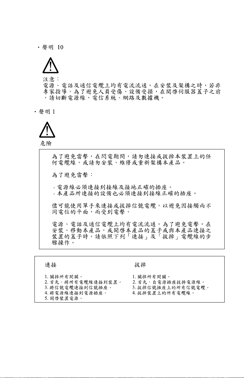
To avoid a shock hazard, do not connect or disc o nnect any c a bl es or perform
installation, maintenance, or reconfiguration of this product during an electrical
storm.
To avoid shoc k haz ard:
•
The power cord must be connected to a properl y wired and earthed
receptacle.
•
Any equipmen t to w h i ch t his product will be attached must also be
connected to properly wired recept acles.
When possib le, use one hand to connect or disc o n nect signal cables to
prevent a possibl e shock from touching tw o s u rfaces with different el ectrical
potentials.
Electrical current from power, telephone, and communications cables is
hazardous. To avoid shock haz a r d, c onnect a nd disconne ct cables as
described followin g when in stalling, moving, or op e n ing cov ers of this product
or attached devices.
To Connect
1. Turn Everything OFF. 1. Turn Everything OFF.
2. First, attach all cables to devices. 2. First, remove power cord(s) from outlet
3. Attach signal cables to receptacles. 3. Remove signal cables from receptacles.
4. Attach power cord(s) to outlet. 4. Remove all cables from devices.
5. Turn device ON
CAUTION:
To Disconnect
When replacing the battery, use only IBM Part Number 33F8354 or
an equivalent type battery recommended by the manufacturer. If your
system has a module contain ing a li t hium battery, replace it only with the
same module ty pe made by the same manufacturer. The battery
contains lithium and can explode if not properly used, handled, or
disposed of.
Do not:
•
Throw or immerse into water
•
Heat to more than 100°C (212°F)
II
Page 11

•
Repair or disassemble
Dispose of the battery as required by local ordinances o r regulations.
CAUTION:
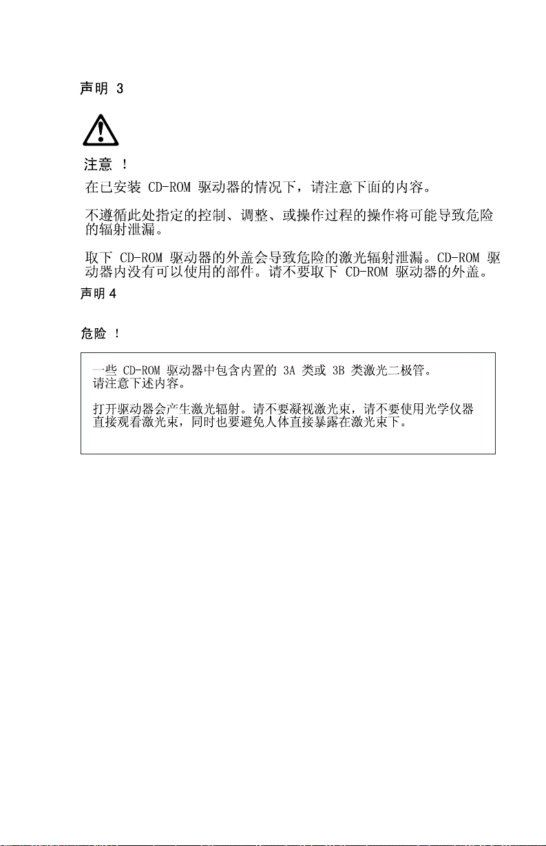
When a CD-RO M drive is i n st al l ed, no t e the fo l low ing.
Use of controls or adjustments or perf o rmance o f pro c e dure s other than those
specified herein might result in hazardous radiation exposure.
Removing the covers of the CD-ROM drive could result in exposure to
hazardous laser radiation. There are no serviceable parts inside the CD-ROM
drive. Do not remo v e the CD- R OM drive covers.
DANGER
Some CD-ROM drives contain an embedded Class 3A or Class 3B laser diode.
Note the following.
Laser radiation when open. Do not stare into the beam, do not view directly
with optical inst ruments, and avoid direct exposure to the beam.
CAUTION:
Electrical current from power, telephone, and communication cables can be
hazardous. To avoid personal injury or equipment damage, disconnect the
attached power cords, telecommunications systems, networks, and modems
before you open the server covers, unless instructed otherwise in the
installation and conf igura t ion procedures.
PERIGO:
Para evitar choques elétricos, não conecte ou desconecte nenhum cabo, nem
efetue instalação, manutenção ou reconfiguração deste produto durante uma
tempestade com raios.
Notices III
Page 12

Para evi ta r choque s elétricos:
•
O cabo de al im e nta ção deve ser conectado a um receptáculo
corretamente instalado e aterrado.
•
Todos os equipamentos aos quais este produto será conectado devem
também ser conectados a receptáculos corretamente instalados.
Quan do poss ível, utilize uma das mãos para conectar ou desconectar cabos
de sinal, para evitar um possível choque ao tocar duas superfícies com
potenciais elétricos diferente s.
A corrente elétrica proveniente de cabos de alimentação, de telefone e de
comunicação é perigosa. Para evitar choques elétricos, conecte e desconecte
os cabos confo rme descrito a seguir, ao instalar, movimentar ou abrir tampas
deste produto ou de dispositivos conectados.
Para Conectar
1.DESLIGUE tudo.
2.Cone cte primeiro todos os cabo s nos
dispositivos.
3.Con ec te os cabo s de sinal no s
receptáculos.
4.Conecte o(s) cabo(s) de alimentação
nas tomadas.
5.LIGUE o dispositivo
Para Desconectar
1.DESLIGUE tudo.
2.Remova primeiro o(s) cabo(s) de
alimentação das tomadas.
3.Remova os cabos de sinal dos
receptáculos.
4.Remova todos os cabos dos
dispositivos
CUIDADO:
Ao s ubstituir a ba t eria , u t ilize apenas o Número de Peça IBM 33F8354 ou um
tipo de bateria equivalente recomendado pelo fabricante. Se seu sistema
possuir um módulo com uma bateria de lítio, substitua-o apenas pelo mesmo
tipo de módulo, produzido pelo mesmo fabricante. A bateria contém lítio e
pode explod ir se não for utilizada, manuseada e descartada de forma
adequada.
Não:
•
Jogue ou coloque na água
•
Aqueça a ma is de 10 0°C (212°F)
•
Con serte nem desm onte.
IV
Page 13

Descarte a ba teria conforme requerido pelas disposi ções e regulamentações
locais.
CUIDADO:
Quando uma unidade de CD-ROM estiver instalada, observe o seguinte.
A utilização de controles ou aj us tes ou a exec ução de p roc edimentos
diferentes daqueles especificados nesta publicação pode resultar em
exposição perigosa à radiação.
A remoção das tampas da unidade de CD-ROM pode resultar em exposição a
radiação perigosa de laser. Não existem peças que possam ser consertadas
no interior da unidade de CD-ROM. Não remova as tampas da unidade de CD-
ROM.
PERIGO:
Algumas unidades de CD-ROM contém um diodo de laser da Classe 3A ou da
Classe 3B. Observe o seguinte.
Radiação de laser quando aberto. Não olhe diretamente para o feixe de laser,
não olhe diretamente com instrumentos óticos, e evite exposição direta ao
raio.
CUIDADO:
A corrente elétrica proveniente de cabos de alimentação, de telefone e de
comunicação é perigosa. Para evitar ferimentos pessoais ou danos aos
equipamentos, desconecte os cabos de alimentação, sistemas de
telecomunicação, redes e modems antes de abrir as tampas do servidor, a
menos que rece ba outr as instruções nos procedimentos de instalação e
configuração.
Notices V
Page 14

VI
Page 15

Notices VII
Page 16
VIII
Page 17
Notices IX
Page 18

X
Page 19
PERIGO:
Pour éviter tout risque de choc électrique, ne m anipul e z aucun câble et
n'effectu ez auc une opération d'installation, d'entretien ou de reconfiguration de
ce produit au c o ur s d'un orage.
Pour éviter tout risque de choc électrique :
•
Les cordons d'alimentation du présent produit et de tous les appareils qui
lui sont connectés doivent être branchés sur des socles de prise de courant
correctement câblés et mis à la terre.
Afin d'éviter tout risque de choc électrique provenant d'une différence de
potentiel de te r r e, n' ut i lise z qu'une m a in , lorsq ue cela est possible, pour
connecter ou déconnecter les cor d on s d'interface.
Le courant électrique passant dans les câbles de communication, ou les
cordons téléphoniques et d'alimentation peut être dangereux. Pour éviter tout
risque de choc électrique, lorsque vous installez ou que vous déplacez le
présent produit ou des périphériques qui lui sont raccordés, reportez-vous aux
instructions ci-dessous pour connecter et déconnecter les différents cordons.
Connexion
1. Mettez les unités hors tension.
2. Commencez par brancher tous les
cordons sur les unités.
3. Br anchez les câbles d'interface sur les
prises.
4. Branchez les cordons d'alimentation sur
un socle de pri s e de couran t.
5. Mettez les unités sous tension.
Déconnexion
1. Mettez les unités hors tension.
2. Commen cez pas d ébrancher les
cordons alimentation des socles de prise
de courant.
3. Débranch ez les câbles d'interface des
prises.
4. Débranch ez tous les câbles des
unités.
ATTENTION:
Remplacez la pile usagée par une pile de référence identique exclusivement -
voir la référence IBM - ou par une pile équivalente recommandée par le
Notices XI
Page 20

fabricant. Si votre système est doté d'un module contenant une pile au lithium,
vous devez le remplacer uniquement par un module identique, produit par le
même fabricant. La pile contient du lithium et présente donc un risque
d'explosion en cas de mauvaise manipulation ou utilisation.
•
Ne la jetez pas à l'eau.
•
Ne l'exposez pas à u ne température supérieure à 100°C.
•
Ne cherchez pas à la réparer ou à la démonter.
Pour la mise au rebut, reportez-vous à la réglementation en vigueur.
ATTENTION:
Si une unité de CD-ROM est installée, prenez connaissance des informations
suivantes :
Pour éviter tout risque d'exposition au rayon laser, respectez les consignes de
réglage et d'utilisat ion des commandes, ainsi que les procédures décrites dans
le présent docu ment.
Pour éviter une exp osition directe au rayon laser, n'ouvrez p as l'unité de CD-
ROM. Vo us ne pouvez effectuer aucune opération de maintenance à l'intérieur.
PERIGO:
Certaines unités de CD-ROM contien nen t une dio d e laser d e c lasse 3A ou 3B.
Prenez connaissance des informations suivantes :
Rayonnement laser lorsque le carter est ouvert. Évitez de regarde r fixement le
faisceau ou de l'observe r à l'aide d'instruments optiques. Évitez une exposition
directe au ra yon.
ATTENTION:
Le courant électrique circulant dans les câbles de communication et les
cordons téléphoniques et d'alimentation peut être dangereux. Pour votre
sécurité et celle de l'équipement, avant de retirer les carters du serveur, mettez
celui-ci hors tension et déconnectez ses cordons d'alimentation, ainsi que les
câbles qui le relient aux réseaux, aux systèmes de télécommunication et aux
XII
Page 21
modems (sauf ins tru ction contraire me ntionnée dans les procédures
d'installation et de configuration)
.
VORSICHT:
Aus Sicherheitsgründen bei Gewitter an diesem Gerät keine Kabel
anschließen oder lösen. Ferner keine Installations-, Wartungs- oder
Rekonfigurationsarbeiten durchführen.
Aus Sicherheitsgründen:
•
Gerät nur an eine Schutzkontaktsteckdose mit ordnungsgemäß geerdetem
Schutzkontakt anschließen.
•
Alle angeschlossenen Geräte ebenfalls an Schutzkontaktsteckdosen mit
ordnungsgemäß geerdetem Schutzkontakt anschließen.
Signalkabel mögli ch st einhändig anschließen oder lösen, um einen
Stromschlag durch Berühren von Oberflächen mit unterschiedlichem
elektrischem Potential zu vermeiden.
Elektrische Spannungen von Netz-, Telefon- un d Datenübertragungsleitungen
sind gefährlich. Um einen Stromschlag zu vermeiden, nur nach den
Anweisungen arbeiten, die für Insta llation, Transport oder Öffnen von
Gehäusen dieses Produkts oder angeschlossenen Einheiten gelten.
Kabel anschließen
1.Alle Geräte ausschalten und
Netzstecker ziehen.
2.Zuerst alle Kabel an Einheiten
anschließen.
3.Signalkabel an Anschlußbuchsen
anschließen.
4.Netzstecker an Steckdose anschließen.
5.Gerät einschalten.
ACHTUNG:
Kabel lösen
1.Alle Geräte aussc h alten.
2.Zuerst Netzstecker von Steckdose
lösen.
3.Signalkabel von Anschlußbuchsen
lösen.
4.Alle Kabel von Einheiten lösen.
Notices XIII
Page 22

Eine verbrauchte Batte rie nur durch eine Batterie mit der IBM Teilenummer
33F8354 oder durch eine vom Hersteller empfohl ene Batterie ersetzen. Wenn
Ihr System ein Modul mit einer Lithium-Batterie enthält, ersetzen Sie es i mmer
mit dem selben Modultyp vom selben Hersteller. Die Batterie enthält Lithium
und kann bei unsachgemäßer Verwendung, Handhabung oder Entsorgung
explodieren.
Die Batterie nicht
•
mit Wasser in Berührung bringen.
•
über 100 C erhitzen.
•
reparieren oder zerlegen.
Die örtlichen Bestimmungen für die Entsorgung von Sondermüll beachten.
ACHTUNG:
Wenn ein CD-R OM-Laufwerk installiert ist, beachten Sie folgend es. Steuerund Eins tellelemente sowie Ver fahren nur en tsprechend den Anweisungen i
vorliegenden Handbuch einsetzen. Andernfalls kann gefährliche
Laserstrahlung auftreten.
Das Entfernen der Abdeckungen des CD-ROM-Laufwerks kann zu
gefährlicher Lasers t rahlung füh r en . Es b efinden sich keine Teile innerhalb des
CD-ROM-Laufwerks, die vom Benutzer gewartet werden müssen. Die
Verkleidung des CD-ROM-Laufwerks nicht öffnen.
VORSICHT:
Manche CD-ROM-Laufwerke enthalten eine eingebaute Laserdiode der
Klasse 3A oder 3B. Die nachfo lg end aufgeführten Punkte beachten.
Laserstra hlung bei geöff neter Tür. Niemals direkt in den Laserstrahl sehen,
nicht direkt mit optischen Instrumenten betrachten und den Strahlungsbereich
meiden.
XIV
Page 23

ACHTUNG:
An Netz-, Telefon- und Datenleitungen können ge fähr liche elektrische
Spannungen anliegen. Um eine Gefährdung des Benutzers oder
Beschädigung des Geräts zu vermeiden, ist der Server auszuschalten. Die
Verbindung zu den angeschlossenen Netzkabeln,
Telekommunikat ionss yst emen , Net z werke n und M ode m s ist v or dem Öffnen
des Servergehäuses zu unterbrechen (sofern i n I ns tallations- und
Konfigurationsa nweisungen n icht anders angegeben)
PERICOLO:
Per evitare il peric olo di sco sse elettriche duran te i t em p orali, non collegare o
scollegare cavi, non effettuare l'installazione, la manutenzione o la
riconfigurazione di questo prodotto.
Per evitare il pericolo di scosse elettriche:
•
collegare il cavo di alimentazione ad una presa elettrica correttamente
cablata e munita di terra di sicurezza;
•
collegare quals iasi app are cchi a tura colle ga t a a questo prodotto ad una
presa elettrica c orr etta men t e cablata e munita di ter ra di sicurezza.
Quando possibile, collegar e o scollegare i cavi di segnale con u na sola mano
per evitare il rischio di scosse derivanti dal contatto con due superfici a diverso
potenziale ele ttrico.
La corrente elettrica circolante nei cavi di alimentazione, del telefono e di
segnale è pericolosa. Per evitare scosse elettriche, collegare e scollegare icavi
come descritto quando si effettuano l'installazione, la rimozione o l'apertura dei
coperchi di questo pro dotto o durante il col leg am ent o delle unità.
Notices XV
Page 24

Per collegare
1.SPEGNERE tutti i dispositivi.
2.Collegare pri ma tutti I cavi alle unit à.
3.Collegare i cavi di segnale alle prese.
4.Collegare il(i) cavo(i) di alimentazione
alla presa elettrica.
5.ACCENDERE le unità.
Per scollegare
1.SPEGNERE tutti i dispositivi.
2.Rimuovere prima il(i) c avo(i) di
alimentazione dalla pres a elettrica.
3.Rimuovere i cavi di segnale dalle prese.
4.Rimuovere tutti i cavi dalle unità.
ATTENZIONE:
Quando si sostitu isce la batteria, utilizzare solo una batter ia I BM o batterie
dello stess o tipo o di tipo equivale nte c o nsigliate dal pro dut tore. Se il sistema
di cui si dispone è provvisto di un modulo contenente una batteria al litio,
sostituire ta le ba tt eri a so lo con un tipo di modulo ugu al e a quello fornito dal
produttore. La batteria contiene liti o e può esplodere se utilizzata, maneggiata
o smaltita impropriamente.
Evitare di:
•
Gettarla o im merg e rla i n acqua
•
Riscaldarla ad una temper a tura s uperi ore ai 100°C
•
Cercare di ripararla o smaltirla
Smaltire secondo la normativa in vigore (D.Lgs 22 del 5/2/97) e successive
disposizioni nazionali e locali.
XVI
Page 25

ATTENZIONE:
Quando è installata un'unità CD-ROM, notare quanto segue:
L'utilizzo di controlli, regolaz ioni o l'esecuzio n e di p r ocedur e non descritti nel
presente manuale poss o no p r ovoc are l'esp osizi one a radiazi oni pericolose.
L'apertura di un'unità CD-ROM può determinare l'esposizione a radiazioni
laser pericolose. All'interno dell'unità CD-ROM non vi sono parti su cui
effettuare l'assistenza tecnica. Non rimuovere i coperchi dell'unità CD-ROM.
PERICOLO:
Alcune unità CD-ROM contengono all'interno un diodo laser di Classe 3A o
Classe 3B. Prestare att e nz ione a q u anto segue:
Aprendo l'unità vengono emesse radiazioni laser. Non fissare il fascio, non
guardarlo direttamente con strume nti ott ici e d evitare l'esposiz ione diretta al
fascio.
ATTENZIONE:
La corrente ci rcol ante nei cav i di alimen ta zione, del telefono e di segnale è
pericolosa. Per evi tar e si tua zioni p eri co lose per le persone o danneggiamenti
all'apparecchiatura, scollegare i cavi di alimentazione, i sistemi di
telecomunicazioni, le reti e ed i modem prima di aprire i coperchi del servente
se non diversamente indicato nelle procedure di installazione e configurazione.
Notices XVII
Page 26

XVIII
Page 27

Notices XIX
Page 28

XX
Page 29

PELIGRO:
Para evi tar una po s i b le descarg a eléctrica, no conecte ni desconecte los
cables ni lleve a cabo ningun a op eración de instalación, de mantenimiento o
de reconfiguración de este producto durante una tormenta eléctrica.
Para evitar una posible desca rga:
•
El cable de alimentación debe con ectarse a un re ceptáculo con una
instalación eléctrica correcta y con toma de tierra.
•
Los aparatos a los que se conecte este producto también deben estar
conectados a receptáculos con la debida instalación eléctrica.
Cuando sea po sible, utili ce un a sol a mano para conectar o desconectar los
cables de se ña l a f i n de ev itar un a pos ible desc arga a l tocar dos superficies
con distinto p ote ncial eléctrico.
La corriente eléctrica de los c abl es de com uni ca ciones, teléfono y
alimentación puede resul tar pel igr os a. Para evitar una posible descarga, siga
las indicaciones de conexión y desconexión de los cables siempre que tenga
que instalar, mover o abrir las cubierta s de este producto o d e los dispositivos
acoplados.
Instr u cciones de conexión
1.Apague todos los componentes (OFF).
2.En pr imer lugar, conecte todos lo s
cables a los di spositivos.
3.Conecte los cables de señal a los
receptáculos.
4.Conecte los cables de alimentación a
las tomas.
5.Encienda el dispositivo (ON).
Instrucciones de desconexión
1.Encienda todos los com ponentes (ON).
2.En prim er lugar, retire los cabl es de
alimentación de las tomas.
3.Retire los cables de señal de los
receptáculos.
4.Retir e todos los cables de los
dispositivos.
Notices XXI
Page 30

CAUTION:
Al cambiar la batería, utilice únicamente la batería IBM Número de pieza
33F8354 o un tipo de batería equivalente recomendado por el fabricante. Si el
sistema tiene un módulo que contiene una batería de litio, sustitúyalo
únicamente por el mismo tipo de módulo del mismo f abr ic a nte. La batería
contiene litio y puede explota r si no se utiliza, ma nipula o desecha
correctamente.
Lo que no debe hacer
•
Tirar o sumergir el producto en agua.
•
Exponer el producto a una te m p erat u r a superior a 100°C.
•
Reparar o desmontar e l producto.
Cuando quiera desechar la batería, siga las disposiciones y reglamentaciones
locales.
CAUTION:
Cuando insta le u na unidad de CD-ROM, te nga en cuenta la siguiente
información.
Si se llevan a ca bo controle s o ajus te s o se utilizan métodos que no se
atengan a lo aquí especificado, se puede produ cir una e xposición peligrosa a
las ra di ac iones.
Si se retiran las cubiertas de l a unidad de CD-ROM, se puede producir una
peligrosa exposición a radiaciones de láser. Dentro de la unidad de CD-ROM
no existen piezas rep ara bles . No retire las cubiertas de la unidad de CD-ROM.
PELIGRO:
Algunas unidades de CD-ROM tienen incorporado un diodo de láser de Clase
3A o de Clase 3B Tenga en cuenta la siguiente información.
Cuando la unidad está abierta se generan emisiones de rayos láser. No dirija
la mirada al haz, no lo observe directamente con instrumentos ópticos y evite
la exposición directa.
XXII
Page 31

CAUTION:
La corriente eléctrica de los c abl es de com unicacio n es, de teléfono y de
alimentación puede resultar p eligrosa. Para evitar posibles lesiones o daños
del aparato, desconecte los cables de alimentación, los sistemas de
telecomunicaciones, las redes y los módems antes de abrir las cubiertas del
servidor, salvo que se indique lo contrario en las instrucciones de las
operaciones de instalación y configuración.
Notices XXIII
Page 32

Laser Compliance Stateme nt
The CD/DVD-RO M driv e in t h e computer is a laser produ ct. The CD/DVDROM drive's cla ssification label (sample sho w n belo w ) is l ocated on the drive.
CLA S S 1 LA S E R PRODUCT
APPAREIL A LASER CLASSE 1
LASER KLASSE 1
LUOKAN 1 LASERLAITE
PRODUIT LASE
CATEGORIE 1
The CD/DVD-ROM dr ive is ce rtified in the U.S. to conform to the requirements
of the Department of Hea lt h and Human Services 21 Code of Federal
Regulations ( DHHS 21 CF R) Subchapter J for Class 1 laser products.
In other countries, the drive is certified to conform to the requirements of
EN60825.
Class 1 laser products are not considered to be hazardous. The CD/DVD-ROM
drive has an internal Class 1, 0. 5-milli w at t , aluminum gall i um- ars enide laser
that operates at a w ave len gth of 760 to 810 manometers.
The design of the laser system and the CD/DVD-ROM drive ensures that there
is no exposure to laser radiation abov e a Class 1 level during normal
operation, user maintenance, or servicing conditions.
XXIV
Page 33

Trademarks
The following are tr a d ema rks of the IBM Corporation in the U nited States or
other countrie s o r both:
Aptiva
AT
HelpCenter
IBM
Operating System/2
OS/2
Personal System/2
PS/1
PS/2
Intel, Pentium, MMX, EtherExpress, and LANDesk are trademarks or
registered trademarks of Intel Corporation.
Microsoft, MS-DO S, Windows, and Windows N T a re tr ade marks or registered
trademarks of Microsoft Co rpor a tion.
Other company, product, and service names may be trademarks or service
marks of others.
Notices XXV
Page 34

Preface
This manual contains service information for the
Level A (SL-A)
manual is intended to be used as a stand-alone documen t to service Aptiva
machine type 2170/2171/2172 products. It is divided into the following
chapters:
Notices
this c ompute r.
General Information
Check Procedures
failing Fie ld Replaceabl e Unit (FRU).
Diagnostic Aids
failures.
Repa ir in g In f ormation
and reassemble the computer.
Parts/Test Point Locations
locations of the major parts, jump ers, and c onn ectors .
Safety Inspection Guide
safety problems before putting the machine under a Maintena nce Agreement.
Parts Catalog
individual FRUs.
Appendix A, FRU Number Index
order.
Appendix B , On l i n e Supp o rt Information
information.
contains important safety information and notices required to service
model of the IB M Aptiva Personal Computer, worldwide. This
contains a brief description of this manual.
provides step-by-step instructions that aid in locating the
explains how to use the diagnostics tools for isolating
contains illustrations and descriptions to disassemble
contains illustrations and descriptions of the
contains information about inspecting a machine for
contains descript ions, i llustr a tions, and part numbers for
contains part numbers listed in numerical
contains online support
2170/2171/2172 Service
XXVI
Page 35

Gener al Information
Introduction ......................................................................................................2
Product Overview ........ .............................. ................ .......................................3
Processors (Machine Type 2170) ...... .. .. .. .. .. .. .. .. .. .. .. .. .. .. .. .. .. .. .. .. .. .. ...........3
Processors (Machine Type 2171/2172) .... .. .. .. .. .. .. .. .. .. .. .. .. .. .. .. .. .. .. .. ..........3
Memory ..................................................................................................... 4
External Ports............................ ................ ................ ................................ 4
Diskette Drive ......... .... .... .. .... .... .... .... .... .... .... .... .... .... .... .. .... .... ...................4
Hard Disk Drive ..... ........ ...... ........ ........ ...... ........ ........ ...... ........ ..................5
CD/DVD-ROM Drive .................................................................................5
Multimedia .......... .................. .................. .................. .................................5
Video Cards ....................... .. .. .. .. .. .. .. .. .. .. .. .. .. .. .. .. .. .. .. .. .. .. .. .. .. .. .. .................5
Power Management ..................................................................................5
Power Supply ............................................................................................6
Internal Cabling ............. .. ................ ................ ................ ..........................6
Monitor (Not includ ed with some models) .. .. .... .. .. .. .... .. .. .. .... .. .. .. .... .. .........6
Keyboard ....... .................. ................ ................ .................. ........................7
Mouse .......................................................................................................7
Hardware Interfaces .........................................................................................8
CMOS Reset .... .. .. ................ ................ ................ ................ ..........................10
Power-On P a s s word ................ .. .. .. .. .. .. .. .. .. .. .. .. .. .. .. .. .. .. .. .. .. .. .. .. .. .. .. ................11
Flash (BIOS) U pdat e Procedure ................... .... .. .... .. .... .. .... .... .. .... .. ............... 12
BIOS-contained Mod el Number and Serial Number . .. .. .... .. .. .. .. .... .. .. .. .. .. .......13
BIOS Setup Utility ............................... ................ ................ ...........................14
Working with the Setup Menus ...............................................................14
Viewing System Information,V i deo Informat ion and Model Information . .16
Disk Drives ................. .. ................ ................ ................ ...........................17
Input/Output Ports ................ .. .... .... .. .... .. .... .... .. .... .. .... .... .. .... .. .................19
Power Management ................................................................................20
Startup Opti ons ................... .............................. ......................................21
Date and Time ...................... ........ ........ ........ ...... ........ ........ .....................21
Advanced Options ................ .............................. ................ .....................22
Specifications ... .................. ................ .................. ................ ..........................27
Dimension ( wi dth x dep th x he ight) ................ .. .. .. .. .. .. .. .. .. .. .. .. .. .. .. ...........27
Weight .......... .......................... .......................... .......................................27
Environment ..... .......................... .......................... .......... .........................27
Power consumption .................................................................................28
Electrical input .........................................................................................28
Operating Requi rements ................. .. .. .. .. .. .. .. .. .. .. .. .. .. .. .. .. .. .. .. .. .. .. .. .. ...............2 9
Special Tools ................................... .. .. ................ .. .. .. ................ .. ..................30
Copyright IBM Corp. 1998 1
Page 36

Introduction
This chapter gives a gene ral ov er vie w of the Aptiva Machine Type 2170/2171/
2172, describes the standard and optional features, and details functional and
environmental spe cifica t ions.
2
Page 37

Product Overview
Machine Types 2170, 2171, and 2172 have two PCI slots and one PCI/ISA
shared slot. The 2170 system supports the AMD K6 processor family and while
the 2171 and 2172 supp o rts the Pentium III processors.
The machine ty p es 2171 a n d 21 72 sup port A ccelerated Graphics Port (AGP),
which allows installed system memory to be used as texture memory, yielding
a huge texture footprin t t o enhance 3D g rap h ic al di splay performance.
Listed below are 2170, 2171 and 2172 system features:
Processors (Machine Type 2170)
•
Socket-7 Zero Inser ti o n For ce (ZIF) connector.
•
Detachable C PU fa n sink.
•
One of the following processors can be installed:
- AMD K6 2XT/380 processor; 95MHz external, 3 80 MHz internal, with
3DNow!
- AMD K6 2XT/400 processor; 100MHz external, 400 MHz internal, with
3DNow!
- AMD K6 2XT/450 processor; 100MHz external, 450 MHz internal, with
3DNow!
- AMD K6 2XT/475 processor; 95MHz external, 4 75 MHz internal, with
3DNow!
- AMD K6 2XT/500 processor; 100MHz external, 500MHz internal, with
3DNow!
- AMD K6 3/450 processo r; 100MHz external, 450MHz internal, with
3DNow!
™
technology
™
technology
™
technology
™
technology
™
technology
™
technology
Processors (Machine Type 2171/2172)
Pentium III
•
Includes Intel MMX™ media enhancement technology plus additional 70
Streaming SIMD (Single Instr uc tion Multiple Data) extensions
•
Processor in Single Edge C ont act Ca rtridge II (S.E.C. C . I I, OLGA) with
integrated PBSRAM L2 cache (512K)
•
One of the following processors can be installed:
- Pentium III - 450MHz internal, 100MHz external
- Pentium III - 500MHz internal, 100MHZ external
General Information 3
Page 38

- Pentium III - 550MHz internal, 100MHz external
- Pentium III - 600MHz internal, 100MHz external
- Pentium III - 700MHz internal, 100MHz external
- Pentium III - 750MHz internal, 100MHz external
Memory
•
512-KB Pipeline Burst Static RAM (PBSRAM). Fixed onboard for 2170,
built-in Pentium III processor s f or 2 171/2172
•
8-MB video Synchronize DRAM (SDRAM). Fixed onboard only for 2170
non-UMA model, built-in AGP video adapter card for 2171 and 2172
•
168-pin Synchronous Dyn amic Random Access Memory (SDRAM), Dualin-line Memory Module (DIMM) sockets.
- 2 memory sockets.
- 8-MB, 16-MB, 32-MB, 64-MB or 128-MB DIMM.
- PC-100 (64-bit , non - E CC, 100MHz, 3.3volt) DIMMs with g old contacts
- Maximum memory is 256 MB.
External Ports
•
Video port (15-pin D-sub conn ector)
•
Parallel port (25-pin D- sub connector)
•
Serial port (9-pin D-sub connector). 2170 has one serial port while 2171 and
2172 have two.
•
Game/MIDI po rt (15-pin D-sub c onnector)
•
Keyboard port (6-pin PS/2 mini-din connector)
•
Mouse por t (6-pin PS/2 mini-din connector)
•
Two USB ports.
•
Microphone-in jack
•
Speaker-out jack
•
Line-in jack
Diskette Drive
•
AT-type
•
3.5-in. 1.44 MB slimline diskette drive.
•
3.5-in. 100MB / 250MB ZIP drive
4
Page 39

Hard Disk Drive
•
3.5-in., 1- in. height IDE AT drive. (3.5-in may b e in aco ustic mounting
bracket)
•
128 KB “look-ahead” cache memory in hard disk drive.
•
Average and minimum 12 ms seek time, access time varies for the hard disk
drive and the hard disk drive m an u facturer.
CD/DVD-ROM Drive
•
5.25-in. high-performanc e , 4 0 X C D- ROM or 6X/32X DV D-R O M o r 4X2X24
CD-R/W IDE/AT drive.
•
Read data and play audio from standard and mini CD-ROM and audio
compact discs (au dio C D s). DV D m edia supported on DVD models.
Multimedia
•
A pair of exter nal active s p eak e rs with power adapter for 2171/2172 or
passive speakers for 2170.
•
Noise canceling microp hone (available on certain models)
Video Cards
•
Savage IV AGP 2x/4x 16MB for 2171/2172
- Same as 8MB card with a VGA connector, but has only 2 memory chips on
board (as oppose d to 4 in the 8MB).
- Has Digital (PnD) Connector
•
Savage IV AGP 2x/4x 32MB for 2171/2172
- Same as 8MB card with 4 memory chips on board a n d a VGA connector
- Has Digital (PnD) Connector
•
ATI TV Out 16MB for 2171 only
•
Nvidia M64 w/TV Out, 32MB for 2171 only
•
Nvidia NV10 w/TV O u t, 32MB for 2171 only
Power Management
•
Compliant t o A C PI and supports Dis p la y Power Management Signaling
(DPMS) monitor.
•
Software shutdown by Windows 98.
•
System enters standby mode if any of following conditions are met:
- Execute standby from Windows 98 Start menu
General Information 5
Page 40

- Press system power bu t ton if i t se t s to act as standby function.
- System is idle and the standby timer set in the Windows 98 Power Management Property elapses.
Power Supply
•
PC-98 com pa tibl e 145W ATX power supply
•
Searchable high/low voltage selection
Internal Cabling
•
Two 40-pin ribbon cabl es for hard disk drive and CD/DVD-ROM drive.
•
One 34-p in ribbon cable for AT diskette drive.
•
One 4-p in (2-wire) cable for hard disk drive light-emitti ng di ode (LED).
•
One 3-pin (3-wire) cable for power light-emitting diode (LED).
•
One 2-pin (2-wire) cable for power switch.
•
One 4-pin modem voi ce- in/spe aker- o u t cable.
•
56.6 Kbps PCI modem adapter card with data/fax/voice or non-voice
features.
•
Telephone line-out (RJ-11) connector.
•
Telephone line-in (RJ -11) connector.
Monitor (Not included with some models)
•
Super Video Graphics Array (SVGA) monitor.
•
Compliant to VES A power saving mode.
•
Connector for a detachable g rounded 3-wi re power cord
•
1.8-m (5.8-ft.) attached signal cable
•
Auto-sensing power input for 100 Vac to 240 Vac
•
15" (13.7" viewable image size) monitor
- 0.28-mm dot pitch
- Automatic scanning horizontal frequencies from 30 KHz to 54 KHz or 30
KHz to 69 KHz (for Japan)
- Vertical frequencies between 50 Hz and 120 Hz.
- DDC2A/B or DDC1/2B+ support (for Japan)
- OSD (On-Screen Display) menu (for Japan)
•
17" (15.7" viewable image size) monitor
- 0.28-mm or 0.27-mm dot pitch (for Japan)
- Automatic scanning horizontal frequencies from 30 KHz to 69 KHz or 30
6
Page 41

KHz to 72 KHz (for Japan)
- Vertical frequencies between 50 Hz and 120 Hz.
- DDC1/2B+ support and OSD (On-S cre en D isp lay) menu
Keyboard
•
104-key, 105-k e y, 1 07-ke y o r 109-key rubber dome Rapid Access™II
keyboard with 1.8-m (5 .8-ft.) cable
•
Preferred Keyboard (for Brazil)
Mouse
•
2 Button PS/2 Sleek or Scro ll Point™ mouse with 1.8-m (5.8-ft.) cable
General Information 7
Page 42

Hardware Interfaces
The following peripheral interfaces for adapters, options, and drives are
supported in the syst em unit.
Item- Interface
Expansion slot for I/O
adapter cards
Hard disk drives Two PCI local bus Enhanced IDE v1.0 compatible hard disk
CD/DVD-ROM/CD-R/W
drive
Disket t e d ri v e AT diskette inter face
Video Physical interface is compatible with the IBM Personal
Modem One 56.6 Kbps PCI modem adapter card with data/fax/voice
Audio Compatible to So und Blaster, Sound Blaster Pro and
Pointing device IBM PS/2-compatible mouse
Keyboar d device IBM PS/2-compatible ke yboard
Three PCI (Peripheral Component Interconnect) v2.1
comp at ible expansion slots th a t operate s at 33 MHz bus
speed.
One IBM AT-ISA Plug and Play compatible expansion slot that
operates at 8 MHz bus sp eed.
Note: T here is 1 PCI/ISA sha red slot
drive interfaces that support:
- PIO mode up to 5 mode
- DMA 32-bit access
Machine Type 2170
- Ultra 33/66 Synchronous DMA (33M/66M bytes/sec.).
Machine Type 2171 and 2172
- Ultra 33 Synchronous DMA (3 3M bytes/sec).
5.25-in. high-perfor mance, 40X CD-ROM or 6X /32X DVDROM or 4 X2X 24 CD-R/W IDE /AT drive.
Support Bootable CD-ROM Format specification version 1.0.
Compliant to Audio-CD, Video-CD, CD-ROM/XA, Karaoke-
CD, and Photo-CD (both single and multi-session) format.
System/2 (PS/2) VGA interface.
Support Accelerated Graphics Port (AGP)
or non-voice features.
Windows Sound Sys te m
8
Page 43

Item- Interface
Serial port
Parallel port Supports SPP (IBM PC/XT, PC/AT, PS/2) compatible, EPP
Game port Game port interface for joystick. It also supports MIDI.
USB Supports Universal HCI Specification for USB 1.0
Machine Type 2170
Supports one high speed NS 16C550 compatible UARTs with
send/receive 16 bytes FIFOs
Machine Type 2171 and 2172
Support two high speed NS 16C550 compatible UAR Ts with
send/receive 16 bytes FIFOs
RS23 2D electrical interface compliant
(IEEE 1284 compliance), ECP (IEEE 1284 compliance)
interface.
IEEE 1284 compliant
General Information 9
Page 44

CMOS Reset
This system does not deny access to BIOS Setup Utility. Execute “Load BIOS
Default Settings” in BIOS Setup to clear the corrupted CMOS data. See
“Loading the Default Settings” on page 15.
10
Page 45

Power-On Password
A power-on password denies access to the system by an unauthorized user
when the system i s power ed on. When a power-on pas sword is active, the
password prompt appears on the screen each time the system is powered on.
The system sta rt s af t er t he proper pass word is entered. See “Power-on
Password” on page 22 for more informatio n a b out how to change, remove and
set password in BIOS Setup.
In some cases, you might be required to service a system with an active and
unknown power-o n pas sword. To clear a password from the system, follow
these steps.
1. Turn off system unit.
2. Unplug power cable fr om the electrical outlet.
WARNING:
Machine Type 2170:
process. See “Machine Type 2170 System Board Jumpers and Connectors” on
page 147.
Machine Type 2171 and 2172:
bypass password check process. See “Machine Type 2171 an d 2 172 System
Board Jumper s and C onnectors ” on page 150.
3. Plug power cable, t urn on the system , and press F1 du ring P OST to enter
BIOS Setup menu.
4. Sel ect “Advanced Options”, then enter “Security Options ” and set “Power
On Password” setting to “None” to clear password.
5. Save and exit from BIOS Setup.
6. Turn off the system, unplug p owe r cable fro m elec tric al outlet.
Machine Type 2170:
process. See “Machine Type 2170 System Board Jumpers and Connectors” on
page 147.
Machine Type 2171 and 2172:
enab le password check p rocess . See “Machine Type 2171 and 2172 System
Board Jumper s and C onnectors ” on page 150.
IMPORTANT:
Setup Utility.
Do not attempt these steps w ith t he power cord plugged into the
electrical outlet. The power supply maintains +5 Vdc of standby power
when the po wer c ord is plugged . Syst e m da mage might result if the
power cord is not unplugge d during jumper setting.
Set JP2 to 1-2 posit ion to bypas s pas s w o rd check
Set switch 5 of S W 1 to the ON position to
Set JP2 to the 2-3 position to enable password check
Set switch 5 of SW1 to the OFF position to
To r e in sta ll the passwo rd, the user must ent e r a password in the
General Information 11
Page 46

Flas h (BIO S ) Update Procedure
NOTE:
1. Prepare a bootable DOS diskette disk with AFLASH.EXE, MSG.DAT,
NOTE:
2. Insert the diskette and boot from drive A.
WARNING:
3. At the DO S prompt, type A:> AFLA SH VXXYYZZ.BIN then press Enter.
4. The program updates th e BIOS a ut omatically.
IMPORTANT: :
5. Wait for the update to complete (indicated by the beeps).
WARNING: :
6. Power off syst e m after the BIOS is completely updated.
The flash update procedure does not change the model number and
serial number information in BIOS.
VXXYYZZ.RN and VXXYYZZ.BIN files
The AFLASH.EXE a nd MSG.DAT are f l as h utility pr ograms. The
VXXYYZZ.RN file has t he BIOS checksum information. The
VXXYYZZ.BIN is BIOS source code binary file.
Do not boot with any memory related driver such as HIMEM.SYS,
EMS.SYS....
Verify the BIOS checksu m value shown on s creen is the same
as the one in VXXYYZZ.RN file.
Do not turn off the system power while the BIOS is programming,
or the flas h ROM will be destroyed.
12
Page 47

BIOS-contained Model Number and Serial Number
The model number and serial number information is sto r ed in BIOS ROM and
displayed i n the “Model Information” of BIOS Setup ma in m e n u. If a service
repair is com ple ted by repl acing a new system board or a new BIOS ROM,
then you are required to input the original system's model number and serial
number into the new BIOS ROM.
Follow these steps to inpu t the model number and ser i a l number to BIOS:
1. Prepare a bootable DOS diskette with CHGDMI.EXE and MODEL.DMI
files.
2. Insert the diskette and boot from drive A.
WARNING:
3. At the DOS pro mpt, type A:>CH GD MI /W then press Enter. When the
screen shows:
System Product Name:
Enter the model number and press Enter to continue. You can type a maximu
of 16 characters (without spaces).
4. When the screen shows:
System Serial Number:
Enter the serial number and press Enter to continue. You can type a maximu
of 16 characters (without spaces).
5. Type A:>CHGDMI/D and press Enter t o displa y an d verify your input model
number and serial number information.
Do not boot with any memory related driver such as HIMEM.SYS,
EMS.SYS....
General Information 13
Page 48
BIOS Setup Utility
The Setup Util i ty le ts you review and change imp orta nt information about the
computer and its hardware.
Working with the Setup Menus
Starting the Setup Utility
Follow these steps to enter Setup when th e computer is off:
1. Turn on your monitor.
2. Turn on the sy st e m unit.
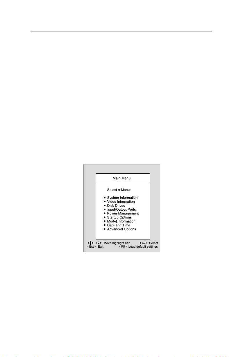
3. When you s ee the IB M Apti va log o, pre s s F1 to en ter Setup and display the
Main Menu.
If you have previously set a power-on p assword, you are prompted to type in
the password after you press the F1 key. See “Power-on Password” on page
22 for informa tio n on sett ing, cha nging , or removing the password.
Refer to the Setup Utility Mai n Menu below.
14
Page 49

The followin g table list s spec ific keys on the keyb oard that will help you move
through the Setup menus:
Keys Function
Down- or up-arrow key Use these arrow k eys to high light an optio n on the
menu. (Press the Enter key to choose the option.)
Left- or right-arrow key Use these arrow keys to make a selection and change
an option's setting. On some menus, you can use these
keys to move from one field to another.
F1 Press this key if you want help for a selected menu
option.
Esc After viewing or making changes to the settings on a
menu, press th is key to exit the menu.
Enter Press this key to choose a highli gh ted optio n from a
F5 Press this key if yo u want to load the factory default
menu
settings from the Main Menu
Changing Parameter Settings
In the Setup menus, the configuration information that you can change is
enclosed in b racket s l i ke t hese : [ ]. You cannot change any information that is
not enclosed in brackets. Use the up- or down- arrow keys to highlight options
then press E n ter to display a menu. When c hangi ng the setting of a particular
parameter, highlight the setting then use the left- or right- arrow key to change
the setting. Ref er to the Setup Utili ty help for det ails on the configurable
parameters i n each menu.
Loading the Default Settings
When you purchase an Aptiva computer, it is already configured for use. The
original configuration settings, also called factory or default settings, are stored
in the CMOS. Setup inc ludes an option Load Default Set t ings that lets you
reload the original configuration at any time.
To load the default settings , follow the se steps:
1. Press F5 to load default setting s. A dialog box appears confirming if you
want to load the default settings.
2. Use the left-arrow key to select Yes, then press Enter.
General Information 15
Page 50

3. Press Esc to exit Setup.
A dialog box appears confirming if you want to save the CMOS settings (in
this case, the defau lt se ttings th at you reloaded).
4. Use the left-arrow key to select Yes, then press Enter to save the changes in
CMOS.
You must load the Setup default settings in the following instances:
•
When you replace the sys tem battery
•
When you customize your system configuration settings and some resource
assignments confl i ct cau s ing the co mp u t er t o stop responding.
Exiting Setup
Press Esc to reture the Main M e n u when you ha v e finishe d vi e wing settings
and making changes. From t his locat i o n , you can exit Setup a n d save your
changes or exit without saving your changes.
Follow these steps to exit Setup:
1. From the main menu, press the Esc key.
2. The Exit Setup dialog box appears. If you have made changes in the
parameter settings, it will contain an option for saving your changes.
- If you would like to sa ve you r c hange s , press the left-arro w key to select
the option Yes then press Enter to save your changes and exit Setup.
- If you do not want to save your changes, press the right-arrow key to select
the option No then press Enter, to exit Setup without saving.
Viewing S ystem Inf o rmation, Vid e o In f ormation a nd Model Information
To view general hard ware info rmatio n abo u t y our computer, select the System
Information option from the Setup main m enu. The items displayed in the
System Infor mati on m enu are not configurable.
Setup automatically updates this menu when you do either of the following:
•
Add or cha nge hardware on your computer
•
Make chang e s to oth er men u s i n Setup and save those changes
To view the video information su ch as the v id eo cont roller and v ideo memory,
select the video information option from the setup menu.
To v ie w the computer information s uch as t h e mo de l number, serial number,
and BIOS version and date, select the Model Information option from the Setup
main menu. Like in the System Information menu, the items displayed are not
configurable.
16
Page 51

Disk Drives
If you install a new diskette, hard disk, or CD/DVD-ROM drive, BIOS autodetects the p resence of these devices. Enter Setup to identify or verify the type
of drive installed in the computer.
If you want to change any drive setting, select Disk Drives from the main menu.
The Disk Dri ves menu appears showing the diskette drive and IDE drive
parameters.
Floppy Drive A
This option displays the size and storage capacity of the currently installed
diskette drive. Empty drive bays are indicated with a “None” setting.
LS-12 0 D r i ve As
This option all o w s u se r t o se t for the LS -120 driv e. Empty drive bays are
indicate d wi th a “Normal” s ettin g. Its possib le s e t tings are:
Normal
removal media.
Drive A
standard diskette drive A exi st s , system automatically identifies it as drive B.
Drive B
ATTENTION:
The LS-120 drive is configured by Windows 98 and acts as an ATAPI
System recognizes the LS-120 drive as drive number 0 (drive A). If a
System recognizes the LS-120 drive as drive B.
If “Boot Sequence” in “Startup Options” is set to CD-ROM and a
bootable CD is loaded, BIOS id entifie s LS- 12 0 (original s e t as drive A)
as drive B and the standard diskette drive becomes inaccessible.
IDE Hard Disk and CD/DV D-ROM Drives
The Disk D r ives menu includ es four IDE dr i ve items that allow you to configure
the hard di s k drive s and the CD /DVD-ROM dri v e. S electing any one of these
items displa y s a submenu with de t ai l s on a particular IDE drive.
The IDE dr ive item s are identified as follows:
•
IDE Primary Channel Master is attached to IDE connector 1 on the syste
board and is se t as the ma ster dev ice. This i s the ha rd disk th at comes
preinstalled wit h your computer.
•
IDE Primary Channel Slave (if installed) is attached to IDE connector 1 on
the system board and is set as the slave device.
•
IDE Secondary Channel Master (if installed) is attached to IDE connector 2
on the syste m board and is set as th e ma ster device.
•
IDE Secondary Channel Slave (if instal l e d) is a tt ached to ID E connector 2
General Information 17
Page 52

on the system board and is set as the slave device . Normally, a preinstalled
CD/DVD-ROM dr i ve is connec ted here.
NOTE: The CD/DVD-ROM drive information does not appear among these
options. Click on th e System I n f or mation option in the Setup main menu
to verify the pres ence of a CD/DVD-ROM drive.
Proceed to t he fol lowing for detai ls o n the parameters under each IDE drive
submenu.
Type This item specifies the number of cylinders, heads, and sectors, and the
size of a particular I DE drive. If no information appears opposite the
parameters, ther e is no drive installed in that channel.
Hard Disk Block Mode This function enhances disk per formance depending
on the hard disk in use. BIOS a ut omat ic all y detects if your hard disk supports
this feature.
Setting to Auto al lows data t ra nsfer in blocks (mult ipl e s ec tors) to increase the
data transfer rate. If your system does not boot after setting this parameter to
Auto, chang e the setting to Disabled. The default setting for this parameter is
Auto.
Advanced PIO Mode The advanced PIO mode feature improves system
performance by allowing the use of faster hard dis k dr ives. If your hard disk
supports this feature, yo u m ay set this p arameter to Auto (default), Mode 0,
Mode 1, Mode 2, Mode 3, or Mode 4 depending on th e hard disk requirements.
See the documenta tion that came with the hard disk.
If your hard disk does not support this function, set this parameter to Disabled.
Hard Disk Size > 528MB This enhan ced IDE feature works only under DOS
and Window s en viro nments. If set to A u to, wh ich is t he default, BIOS allows
you to use a hard disk with a capacity of more than 528 MB. This is made
possible through the Logical Block Address (LBA) mode translation. You may
be required to set this parameter to Disabled if you use other operating
systems.
To prevent data loss, set this parameter to Auto if you are using a hard disk
with more than 528 MB capaci t y t h at was pr eviously configured through the
LBA mode. If you use a hard disk configured through the user-spec ific cylinderhead-sector (CHS) mode, set this parameter to Disabled.
18
Page 53

Hard Disk 32-bit Access Setting th is p ara meter to Enabled improves system
performance by allowing the use of the 32-bi t hard disk access. This enhanced
IDE feature only works under Windows 3.x, OS/2, Windows 95, Windows 98,
and Novell NetWare. If your soft ware do es not s upp ort th is fu n cti on, set this
parameter to Disab led. The d efa ult setting is Enabled.
DMA Transfer Mode Setting this DMA Transfer Mode parameter to Auto will
enhance perfor mance by maximizing the data transfer rate for this dr ive. If set
this parameter to Disable, the data transfer rate will be the most safe PIO mode
4.
Input/O u tpu t Ports
From the Setup m ain menu, select the Input/O utput Ports option to view or
change port configuration settings. The Input/Output Ports menu appears.
This menu l ets you configu r e serial an d parallel ports.
Also include d in this menu are ite ms f o r enabling or disabling the onboard
controller chipsets.
Serial Port
The machine type 2170 c omes with a 9 -p in seria l port. Th is parameter displays
the current address for serial port. The default setting Base Address is 2F8h
and the default IRQ is 3.
For the machine 2171/2172, they come w ith two 9-pin serial por t . Serial port 1
sets to Disable while se rial port 2 se t s the defau l t to E nabled. The default
setting of Ba se Addres s is 2F8h an d the default IRQ is 3.
Parallel Port
Your comput er co me s with one parallel por t. T his para mete r shows the default
Enabled to activate the parallel port. The default base address is 378h and the
default IRQ is 7.
The default mode is ECP. The default DMA is 3.
Onboar d PS / 2 Mouse (I RQ12)
This paramet er en a b les o r disabl es the onboard PS/2 mouse. When set to
Enabled, it allows you to use the onboard PS/2 mouse. When set to Disabled,
it deactivates the mouse and frees I RQ 12 for the use of othe r devices.
General Information 19
Page 54

Onboard USB
This parameter allows you to enable or disable the Universal Serial Bus (USB)
controller. The default setting is E nabled.
USB Keyboard Mode
keyboard outside of Windows. The default is Disabled.
This parameter enables or disables the use of a USB
Onboard PCI Audio Chip
This parame t er en a b les o r disab l es the onboard au d io contro ller chipset. This
item does not ap pear in the menu if there is no physical audio chipset on the
system board. The default setting is Enabled.
Power Management
The system p o wer manage m ent featu res allow y ou to reduce power
consumption.
NOTE:
Power Management Mod
When the Pow er Management Mode para me t e r is s et to Enabled, you can
configure the different power saving timers to your desired settings. Setting this
parameter to Disabled deactivates the power management feature and all the
timers. The default setting is Enabled.
IDE Hard Disk Standby Timer
standby mode after inactivity of 1 to 15 minutes, depending on your setting.
When you access the hard dis k again , allow 3 to 5 seconds (depending on the
hard disk) for t he system to recover and return to normal spe ed. Set this
parameter to Off if your hard disk does not support this function. The default
setting is Off.
System Sleep Timer
minutes) before the system enters the sleep state. Use the arrow keys to select
a setting. You can turn this timer to Off if you prefer. The defau lt setting is 30
minutes.
Stop CPU Clock in Sleep State
stops, along with other internal devices, when the computer enters the sleep
state. W hen s et t o N o, the s ystem internal clock continues to run when the
system is in the sleep state. T h is i tem tu rns gray a n d is non-configurable when
the System Sleep Timer is off. The default setting is Yes.
These Power Management settings do not work in Windows 98. Use
the Control Pa n e l Power utility for Windows 98 Power Management
settings.
This parameter al low s t he h ard disk to enter
This timer allows you to set the period of inactivity (in
When set to Ye s, the system internal clock
20
Page 55

Power Swit c h 4< sec. When set to Suspend, this parameter adds the
suspend function to the system power button on the front panel. The suspend
function allo w s you to put the system into susp e nd mod e by pressing the
power button for less than f o ur se c on d s while t h e system is on. When this
parameter is set t o Po we r off, the po wer button simply turns the system power
on or off. This parameter is set to P ower o ff by default.
Modem Wake-Up on Ring This parameter allows you to enable or disable
the Modem Wake-Up on Ring feature. When enabled and if the computer is in
suspend, an incoming call automatica lly res um es no rmal power on mode.
When disabled, the system does not return to the “Normal on” state even if
there is an i ncom ing mod e m access. The default s etting is Enabled.
Startup Opt ions
From the Setup m ain m enu, sel e ct Startup Options t o view or change start-up
configuration settings.
Fast POST Mode When set to Auto, which is the default, this parameter
allows the system to boot faster by skipping some power on self-test (POST)
routines.
Silent Boot This parameter enables or dis ables the silent boot function.
When set to En abled , which is the d ef ault , BI OS is in gr aphical mode and
displays the IB M l ogo while booting. If an error occurs while booting, the
system automaticall y switches to text mode.
Even if your set ti ng i s Enable d , you may also switch to the text mode while
booting by pressing F9 after you see the message “Press <F1> to go to the
Setup Utility”.
When set to Disabled, BI O S is i n the conve nt i ona l text mod e where you see
the system initialization details on the screen
Num Lock After Boot This parameter displays whether the Nu mLock
function on the keyboard t u r ns on a ut o mat i c al l y e a ch time you turn your
computer on. You can set this to Enabled or Disabled. The default is Enabled.
Boot Sequence This p ara met e r all o w s you to set system boots from Floppy,
Hard Disk or CD-ROM drive.
Date and Time
From the Setup main menu , select the Date and Time option to view or change
the system clock from the Date and Time menu. If you want to change the
system date, enter the date in the format shown on the screen as in the
following example:
Fri Apr 02, 1999
General Information 21
Page 56

If you change the time, enter the time in 24-hour format (hours, minutes,
seconds). For example:
- 12 midnight is 00:00:00
- 12 noon is 12:00:00
- 1 p.m. is 13:00:00
When setting d ate and time, press the up- or down- arrow key to highlight a
field. Press the left or right-arrow key to change the settings.
Advanced Options
From the Setup main menu, select the Advanced Options option to view or
change a variety of configur ation sett ings. The Adva nced Options menu
appears, with the following options:
•
Secu rity Options
•
Memory/Cache Options
•
PnP/PCI Options
Each of these options opens an additional menu.
Secur ity Opt io ns
Power-on P as sword
Select this parameter and press the left- or right arrow key to display the
Power-on Password window. In this window, you can set up a password to
restrict the u se of y o ur comp uter. You can also cha nge or remove the
password.
If you set up a power on password, you must type this pa ss w ord each time you
turn on your computer. If you do not key in t he correct password, you cannot
use your co mp uter. You must als o type this passw ord i f you want to enter
Setup.
Setting a Power-On Password
1. Ent er Setup.
2. From the S etu p main menu, s elect A d v ance d O ption s, t h e n Security
Options.
3. Highlight the Power-on Password parameter and press the left- or rightarrow key to display the Power-on Password window.
4. Type a password consisting of up to seven cha racte r s, t h e n press Enter.
5. Retype the p a ssword then pre ss Enter.
6. Press Enter again to confir m setting the passwo r d. P r ess i ng Esc aborts the
22
Page 57

password se t ting.
After pressing Enter, the Power-on Password win d o w disap pe a rs. The
Power-on Password pa rame ter autom at ic al ly set s to Present.
7. Pr ess Esc to return to Setup main menu.
8. Press Esc to exit Setup and reboot the system. Answer Yes when prompted
to s ave settin gs.
The next time you turn on the system, you will be prompte d to enter your
power-on passw or d. If you press F1 during POST to enter Setup, you must key
in the password as well.
If you were not able to set a password after performing the above procedure, or
should you encounter any err o r messa g e wh en sett i ng a pas s word, refer to
“Power-On Password” on page 11 about how to set the hardware jumper to
bypass password check.
Changing the Po we r- O n P a ssword
1. Ent er Setup.
2. Key in your current password when prompted.
3. From the S etu p main menu, s elect A d v ance d O ption s, t h e n Security
Options.
4. Highlight the Power-on Password parameter and press the left- or rightarrow key twice to display the Power-on Password window.
5. Type in a new password then press Enter.
6. Retype th e new pass word t h en press Enter.
7. Press Enter again to c onfi r m c han ging the password.
8. Pr ess Esc twice to return to the Setup main menu.
9. Press Esc to exit Setup and reboot the system. Answer Yes when prompted
to save CMOS settings.
If you change your mind a n d decide not to change your password, just
answer No when pro mpted to save CMOS settings.
Removing the P ower-On Password
1. Enter Setup and select Advanced Opti ons, then Security Options.
2. Press the left- or right arrow key once to select None.
3. Pr ess Esc to return to Setup main menu.
4. Press Esc to exit Setup and reboot the system. Answer Yes when prompted
to save CMOS settings.
General Information 23
Page 58

Disk Drive Control
There are two items under this parameter: Diskette Drive and Hard Disk Drive.
These items allow y ou t o wr i te-protect the floppy disk ette and hard disk drives.
The settings include:
Write Protect All Sectors Disables the write f unction all sectors of the
diskette or hard disk d rive.
Write P rotect B oot Sector Disables t he write f unct ion onl y on the bo ot sector
of the diskette or hard disk d rive.
Normal Allows the diskette or hard disk drive to function normally. This is the
default set ting.
Onboard Floppy Disk Controller This par a me ter allows you to enable or
disable to onboard floppy disk controller chipset. When set to Enabled, the
controller enables the disket te drive on your computer. When se t to Disabled,
the controller deactivates the drive but simultaneously frees IRQ 6 which is
normally assigned to the diskette drive. You may then assign IRQ 6 to another
device.
Onboard IDE Primary Channel This parameter allows you to enable or
disable the onboar d I DE primary c h annel controller. Setting this parameter to
Enabled lets y ou use the primary IDE connector (IDE 1) to connect up to two
IDE drives. Setting to Disabled deactivates IDE 1 but frees IRQ 14 for the use
of other devices. The defaul t setti ng is Enabled.
Onboard IDE Secondary Channel This parameter allows you to enable or
disable the onboard IDE secondary channel controller. Setting this parameter
to Enabled lets you use the secondary IDE connector (IDE 2) to connect up to
two IDE drives. Sett ing t o D is a bled dea ct i vat e s ID E 2 b ut frees I R Q 15 for the
use of other devices . The default setting is Enabled.
Porcessor Serial Number Access
This paramete r allows you to select Enable to ena ble pro ce s sor serial number
acess on systmes with an Intel pentium III processor. The default setting is
Disable. This par ame ter se tting is only for machine type 2171/2172.
Memory/Cache Options
The Memory/Cach e Options menu allows you to configure the Level 1 and
Level 2 cache s. Enab li ng the cache parameters optimize sy s te m perf o rmance.
Some older app lica tions, h owever, may not run properly with the caches
enabled. Set the pa ra m eters to D isabled when you run these applications.
Disabling the cach es will d egr ad e sys tem p e rformance.
24
Page 59

Level 1 Cache This parameter enables or disables the Level 1 cache memory.
The default setting is Enabled.
Level 2 Cache This parameter enables or disables the Level 2 cache memory.
The default setting is Enabled.
Memory Configuration This paramet er shows the installed memory
configuration inform ation.
PnP/PCI Options
The parameters i n the PnP/ PCI Option s menu al l ow you to se t the IRQ
assignments for your PCI devices.
PCI IRQ Setting This parameter allows for auto matic or manual configuration
of PCI devices. If you us e Plug and Play devices, you can keep the default
setting Auto. The system then automatically configures the Plug and Play
devices. If you i nstall non-Plug and Play ada p t er ca rds , set this parameter to
Manual. This all ows you to assign resources to non-Plug and Play cards first.
PCI IRQ Sharing Wh en set to Yes, this parameter a l l ows you to assign the
same IRQ to more than one PCI device installed in the system. When set to
No, you must assign different IRQs to the P CI devices. The default s etting is
Yes.
VGA Palette Snoop The V GA p alet t e sno o p function a l lows the system to
refresh all ISA and PCI graphic adapters installed in the system. This is
needed if you install an additional graphics overlay card such as an MPEG or
an advanced 3D graphics adapter. If the image on your monitor has problems
after installing such an adapter, set this p ara meter to Ena bled. Otherwise,
leave it to the default Disabled to achieve better performance.
Plug and Play Operating System When this parameter is set to Yes, BIOS
initializes only Plug and Play boo t devices, then t h e Plug and Play operating
system takes care of t h e other dev ic e s . When set to No, BIOS initializes all
Plug and Play boot and n on- b oot devices.
Set this parameter to Yes if you are using the Windows 95 or Windows 98
operating system. Set t o No i f you ru n any other opera ti ng system. The default
setting is Yes.
Reset Resource Assignments Set this paramete r to Yes to avoid IRQ
conflict when installing non-Plug and Play cards.
Before you install non-Pl ug and Pla y cards, set th is pa rameter to Yes, exit
Setup and turn of f the computer. T his clears all resou r ce assignments and
allows BIOS to reassign resources to all installed Plug and Play devices the
General Information 25
Page 60

next time the syste m boots. Aft e r clearing the resource data, the parameter
resets to the def aul t settin g No.
26
Page 61

Specifications
Dimension (width x depth x height
•
For Machin e Type 2170/2171:
System unit: 190 mm (7.48 in.) x 370 mm (14.57 in.) x 384 mm (15.12 in.)
For Machine Type 2172:
System unit: 195 m m (7.68 in.) x 455 mm (17.9 in.) x 428 mm (16.85 in.)
•
15" Monitor: 370 mm x 396 mm x 382 mm
•
17" Monitor: 413 mm x 445 mm x 434 mm
Weight
•
For Machin e Type 2170/2171:
System unit: 12.7 kg (28 lb)
For Machine Type 2172:
System unit: 10 k g (22 lb)
•
15" Monitor: 13.0 kg (28.6 lb)
•
17" Monitor: 18.5 kg (40.8 lb)
Environment
•
Temperature f or system unit:
- Power on: 10
- Power off: -10
•
Temperature for 15" monitor:
- Power on: 5
- Power off: -20
•
Temperature for 17" monitor:
- Power on: 10
- Power off: -20
•
Humi d ity for system unit:
- Power on: 20% to 80
- Power off: 20% to 80
•
Humidity for monitor (15" and 17"):
- Power on: 20% to 80
- Power off: 20% to 90
to 35°C (50° to 95°F)
°
to 60°C (14° to 140°F)
°
to 40°C
°
to 60°C
°
to 35°C
°
to 60°C
°
General Information 27
Page 62

Power consum pt ion
•
System unit: Maximum 145 Watts
•
15" monitor: Maximum 80 Watts
•
17" monitor: Maximum 130 Watts
Electrical input
•
Input voltage for system unit (Sine-wave input is required)
- Low Range: 90 Vac to 132 Va c
- High Range: 180 Vac to 264 Vac
•
Input vo ltag e for 15" monitor (Sine-wave i n put is required)
- 88 Vac to 264 Vac
•
Input vo ltag e for 17" monitor (Sine-wave i n put is required)
- 90 Vac to 264 Vac (17")
28
Page 63

Operating Requireme nts
All machines require two power inputs: one on the system unit and one on the
monitor display.
The system units come with a voltage sel ector switch, allowing selection of
voltage of eit her 115 V a c or 230 Vac. This swit ch must be in the 230 Vac
position when th e m ac hin e is plugged into a 230 Vac electrical outlet.
The required power input for t he mon itor (Not included wit h some models)
shipped with t h e syste m uni t is auto-sensing type and does not require any
voltage switch adjustment.
General Information 29
Page 64

Speci al Too ls
The followin g spec i al t oo l i s required to service this system when running
diagnostics program (PC-Doctor):
•
Wrap plu gs , P/N 72X8 546
30
Page 65

Check Procedures
Introduction ....................................................................................................32
Start ...............................................................................................................33
Index of Symptoms, Messages, Error Codes, or Beeps ...... .................. .. ......37
Troubleshooting .............................................................................................53
Factory-Insta lle d Storag e Devices ....... .. .... .... .. .... .... .. .... .... .. .... .... ........... 5 3
Factory-Installed Modem Card .......................................................................56
Audio (Not S up ported by Diagnostics Program) ................ .. .. .. .. .. .. .. .. .. .. ........58
CD/DVD-ROM Drive ......................................................................................60
Memory ........ ........................ ...................... ...................... ..............................61
Keyboard . ................ .............................................. .........................................62
Mouse ............................................................................................................63
Power Supply .................................................................................................65
Monitor ..... .......................... ........................ ........................ ............................68
Undetermined Problems ..................... .. .. .. .. .. .... .. .. .. .. .. .. .. .. .. .. .. .. .. .. .. ...............70
Copyright IBM Corp. 1999 31
Page 66

Introduction
This chapter contain s the che c k proc edures used to diagn ose the causes of
product failur e s . The diagn ost ic i nf ormatio n c o nsists of:
Start:
This is the starting point for any diagnostic action. Based on high-level
symptoms, th e check p roce d ure directs you to more d etail ed procedures to
help resolve machine fai lures.
Index of Sy m p toms, Mess age s, Error Codes, o r Beeps:
BIOS Error Messa ges , Cod e s, B e eps, and Error Sympt om s list symptoms
along with their probable causes, and direct you to the applicable check
procedures to help resolve machine failures. These tables also list the field
replaceable units (FRUs) mo st likely to ca use a parti cul ar problem.
Check Procedures:
Symptoms, Messages, Error C ode s , or Beeps tables point you to a specific
check procedur e , proceed to that secti o n. If th ere are any notes or i nstructions
at the top of the page, read them before you begin with the procedure.
Carefully r ead eac h ste p of the check procedure and perform the steps as
instructed. If you do not remember the location of a specific part or test point,
or an adjustment or removal procedure, see the chapter that contains that
information. A l ways r eturn t o the check proced ure afte r you do this. In some
cases, you are r efe rr ed to other c heck procedures to detect the ca use of the
failure.
When the Start check proc edur e or th e Index of
The tables for
32
Page 67

Start
This is the entry point for all check procedures. The chec k pro c edures use
failure symptoms, Po we r -On Sel f Test (POST ) err o r codes, or beeps to help
determine the defective field replaceable unit (FRU ). Fol low the suggested
che ck procedu res or use the diagnostic s diske tte to determine th e proble
FRU.
IMPORTANT:
result of software, loose contacts, or dirty component surfaces. Any FRU
change should be verified by running a complete test (“Diagnostics - All
Tests” in PC-Doctor diagnostics program).
This book comes with a diagn ostic program diskette . This diskette should be
used ONL Y with
Computers. Do not use this diskette on other models.
POST error codes and error messages are displayed on the screen after the
IBM logo. Meanwhile, error be eps could be issued to h e lp d iagnose system
problem. Please refer to “Index of Symptoms, Mes s ages, Error Codes, or
Beeps” on page 37 for additional help.
All voltages i n t he check procedures are positive unless otherwise indicated.
Use frame ground for all voltage checks u nless otherwise specified.
IMPORTANT:
machine, just above t he connector for the pow er c ab le. If the system
does not power on after pressing the power button situated on the front
of the machine , please check the power cable and the Power Override
switch. If the Power Override switch is switched on, no power is supplied
to the system.
NOTE:
message persists, an optio n adapter card might be causing the failure.
Remove al l op tion adapter cards , one at a time, until the error changes
or the pro bl em is no longer apparent. Replace the last option adapter
card re mov ed.
Replace FRUs ONLY when it is determined that the error is not a
2170/2171/2172 Service Level A (SL-A)
There is a Power Override switch located at the back of the
If the check procedu res in stru ct you t o r epl ace a FR U and the error
IBM Aptiva Per sona l
The hard disk drive contai ns pre-loaded software. Ref er t o “Software Recovery
Procedure” on page 143, to reinstall the original software. Be sure to reload the
software o n the pri mary hard disk drive (Drive C) when replacing it.
IMPORTANT:
rearranged, or the drive startup sequence has changed. Be extremely
careful during wr ite oper ations, such as copying, s aving, or formatting.
Data or programs can be overwritten if you select a n in c orre ct d rive.
the customer to bac k up any additional software f r om the hard disk
drive before you reload the software.
The drives i n th e s y stem you are servicing m ay have been
Ask
Check Procedures 33
Page 68

How t o Diagnose Combined FRUs: If an adapter or device c onsis ts of more
than one FRU, an y of the FRUs mi gh t c aus e a n error code. Before replacing
the device o r ada pter, remove the FRU s one by one to see if the symptoms
change.
If a newly replaced FRU does not correct the problem: If you have reached
this point of the check proced ures and were in s tructed to replace a FRU but
doing so did n ot c or rect t he problem, reinstall the ori gin al FRU and go through
“Start” again.
If you want to print a copy of a BIOS Setup Utility screen to an attached printer,
press Print Screen key while the following scre en is displayed.
READ THE FOLLOWING:
Human Error is a cause for concern when ap plied to check procedures. It
exists in every first time set of analysis procedur e s. It is therefore
essential for effective an d t im e-ef f i c ient s e rvicing that each stage of
every procedure be verif ied. (For exam pl e : When a sympt o m is found, or
when a symptom appears t o h ave bee n cured; the prece d ing steps
should be repe ated f o r accuracy o f analysis.)
001 - START
•
To begin, note the f o llowing:
•
Disable t h e se ttin g of “Fast POST Mode” in BI OS Setup.
•
To disable or reset the power-on password, see “Power-On Password” on
page 11.
•
Disconnect all external cables and devices including speakers and
microphone from the sy s te m unit, exc e pt for the keyboard , mouse, and
monitor.
•
Power off the system unit (unplug the power cord) before moving it or when
replacing FRUs.
•
Remove all ada pter cards, except for the factory-installed mod em adapter
card and any other IBM Aptiva factory-i ns t alled adap ter cards.
•
Disconnect all drives except:
- 3.5-in. diskette drive
- Hard disk drive
- IBM Aptiva facto ry -ins talled devices (such as a CD-ROM drive)
•
Ensure th at all power cords a n d cab les are connected properly.
•
Ensure that t he monito r brigh tne s s and contrast co n t rols are not turned
down.
34
Page 69

•
Power on the system unit.
NOTE: Some monitors have a detachable system I/O signal cable between the
monitor and the system unit. In this case, check this signal cable before
replacing the unit. See “Mo nito r Port S i gn als” on page 176 for pin
identification.
•
Ensure correct monitor refresh rate.
•
Note any sympt oms, m ess ages, er r or cod es, or beeps.
•
Make sure that there are no diskette or CD in the drives.
002 - DOES AN IBM LOGO SCREEN A PPE A R ? ( Y ES, READ AHEAD. NO,
GO TO STEP 004.)
•
Insert diagnostics d iskette in the diskette drive.
003 - DOES SYSTEM LOAD THE DIAGNOSTICS PROGRAM FROM THE
DISKETTE DRIVE? (YES, READ AHEAD. NO, GO TO STEP 004.)
•
Follow the instructions on the screen and select Utility from the diagnostics
program menu.
•
Select Tech Support Form from the menu, pr es s F5 to execute, then
generate a system configuration report.
•
Compare the system configuration list with the actual devices installed in
system.
NOTE: If necessary, remove the machine cover and visually compare the
devices installed in system to those shown in the system configuration
report.
•
Go to step 006.
004 - DO ANY MESSAGES, E R R OR CODES, OR SYMPTOMS APPEAR?
(YES, READ AHEAD. NO, GO TO STEP 005)
•
Go t o “Index of Symptoms, Messages, Error Codes, or Beeps” on page 37.
•
End.
005 -
•
If the keyboard responds incorrectly, go to “Keyboard” on page 62.
•
If monitor problems appear, such as jittering, shifting, or being out of focus,
go to “Monitor” on page 68.
006 - DOES THE SYSTEM CONFIGURATIO N R E P O R T CORRECTLY
IDENTIFY T H E DEVICES I N STALLED IN SYSTEM? (Y E S , READ AHEAD.
Check Procedures 35
Page 70

NO, GO TO STEP 007.)
•
Select Diagnostics from the diagnostics program menu.
•
Select and execute All Tests.
- Go to step 008.
007 -
•
The system configuration report shows only those devices supported by the
diagnostics dis kette.
•
If a device is missing from the list and is not factory installed, refer to the
service m anual p ro vided for that device.
008 - DO THE DIAGNOS TICS FINISH W I THOUT ANY ERRORS? ( YES,
READ AHEAD. NO, GO TO STEP 009.)
•
If the Diagnostics \ All Tests did n o t detect a failure but the system still
indi ca tes a failu re :
- Check all adapter card jumper settings.
- Check all adapter card switch settings.
- Check all adapter card cables and con n ectors. Make sure th at all of the
above are set c or rec tl y and show the corr e ct voltages and continuity. Replace any defective cables or adapter cards. See “Parts/Test Point Loca-
tions” on page 145.
- Run the Diagnostics \ All Tests again.
- If an error or other symptom is displayed, go to “Index of Symptoms , Mes-
sages, Error Codes, or Beeps” on page 37.
- If no error can be detected or the symptom is intermittent, go to “Undeter-
mined Problems” on page 70.
•
End
009 -
•
If the last test stops a n d you c an not conti nu e , f i rst ma k e sure all switches,
power connectors, cables, and j ump ers are set correct ly and show the
correct vo ltage s a nd continuity.
•
Ta k e note of any me ssages , error cod es, be e ps , or new symptoms. Go to
“Index of Symptoms, Messages, Error Codes, or Beeps” on page 37.
•
If there is no er ror symp tom or the error symptom is intermittent, go to
“Undetermined Problems” on page 70.
36
Page 71

Index of Sy mpt oms, Messages, Error Codes, or Beeps
How to Use Error Mess ages:
combinations that occur to diagnose failures. If more than one failure occurs,
begin the diagnosis from the first failure that appea r ed. T he c au se of the first
failure can r esul t in false messages, error cod e s, or b eeps. If you did not
receive any m ess ages, e r r or c odes, or b ee ps, see i f the symptom is listed in
“Table 2-3 Error Symptoms List” on page 44.
CAUTION:
POST:
On Self Test (POST). The machine performs t he P O ST each time it is powered
on. Use this information throughout the diagnos t ic p roc e d u r es . The POST is a
series of system check s and initial izations t hat ver ify the correct operation of
the base system.
After a successful POST, the system attempts to load operating system. The
system can be customized for different startup (boot) methods by the BIOS
Setup Utility. “Startup Options” on page 21.
The system' s de fault st artup sequ en ce automat ically looks for the operating
system files in the hard disk if these files are not found in the diskette.
WARNING:
When you have deemed it necessary to replace a FRU, and have
done so, you must run a total system check to ensure that no other
activity ha s been affe cted by the chang e. T hi s s y stem check can be
done through the di agnostics program (Select Diagnos tics , then select
and execute All Tests from PC-Doctor).
Some diagnostic aids are r es ident in the machine, such as the Power-
Remember that POST does not test all areas, but only those that
allow th e system to operate well enough to run the diagnostics program.
Use the messages, error codes, and beeps
Table 2-1 lists BIOS error codes, m essag es, to their pos s ible causes. table 2-2
lists BIOS b eep s t o their po s s ibl e cau s es. Table 2-3 lists error symptoms and
their possible causes. The m os t likel y caus e is listed first. Make sure you
complete all items in the cause or “Action/FRU” column. When servicing a
system, always begin with “Start” on page 33.
If you are unable to cor re ct the p ro b lem usin g these two index tables, go to
“Undetermined Problems” on page 70.
NOTE:
1. If an error message and incorrect audio response occur, diagnose the error
2. If you cannot run the diagnostics program tests but did receive a POST error
3. If you cannot run the diagnostics program tests but did receive a POST error
message first.
code and message, us e “Table 2-1 PO ST Error Codes and Messages List”
on page 38 to diag no s e sys te m problems.
Check Procedures 37
Page 72

beeps, use See “Table 2-2 BIOS Error Beeps List” on page 43 to diagnose
system problems.
4. If you did not receive any error message, look for a description of your error
symptoms in “Table 2-3 Error Symptoms Li st” on page 44.
IMPORTANT: Check all power supply voltages, switch, and jumper settings
before you replace the s y s tem board . A l so che c k the power supply
voltages if you have a “system no-power” condition.
5. If you are unable to cor re ct the problem by using the “BIOS Error Codes,
Mes sages, And Beeps List” table and “Error Symptoms List” table, go to
“Undetermined Problems” on page 70.
Table 2-1 POST E rro r Code s and M ess a g es List
NOTE:
T o d iagnose a problem, first find the BIOS error messages or codes in left
column. If directed to a check procedure, replace the F RU in dica ted in t he check
procedure. If no check procedure is indicated, the first Action/FRU listed in right
column is the most likely cause.
BIOS Error Codes, Messages Action/FRU
0111
I/O Parity Error
0129
CPU Clock Mismatch
0151
Real Time Clock Error
0161
CMOS Battery Bad
0162
CMOS Checksum Error
0162
Equipment Configurati on Error
ISA adapter car d
System board
Check CPU speed and system board DIP
switches.
See “Machine Type 2170 System Board
Jumper s and Co nnector s” on page 14 7
System board and “Machine Type 2171
and 2172 System Board Jumpers and
Connectors” on page 150
Enter BIOS Setup and load the default
settings.
CMOS battery.
System board.
Ensure the system configuration set in
BIOS Se t up i s corre ct. “BIOS Setup Utility”
on page 14.
Enter BIOS Setup and load the default
settings.
CMOS battery.
System board.
38
Page 73

Table 2-1 POST E rro r Code s and M ess a g es List
NOTE:
T o d iagnose a problem, first find the BIOS error messages or codes in left
column. If directed to a check procedure, replace the F RU in dica ted in t he check
procedure. If no check procedure is indicated, the first Action/FRU listed in right
column is the most likely cause.
BIOS Error Codes, Messages Action/FRU
For 2170 only
0163
Date and Time Incorrect
For 2170 only
0164
Memory S ize Change
For all machine type
0201
Memory Error at MMMM:SSSS:OOOOh
0301
PS/2 Keyboard Error or Keyboard Not
Connected
0303
PS/2 Keyboard Interface Error
0662
Onboard Floppy Drive I/O Address
Conflict(s)
0662
Onboar d Floppy Drive DMA Conflict(s)
0662
Onboar d Floppy Drive IRQ Conflict(s)
0662
Floppy Disk Controller Error
0662
Floppy Drive A Error
0662
Floppy Drive B Error
0648
Floppy Drive(s) Write Protected
Ensure the time set in BIOS Setu p is
correct. “Date and Time” on page 21.
CMOS battery.
Insert the memor y mo d ules in the DIMM
sockets properly, then rebo ot the system.
Memory module. “005 -” on page 6 1 to
replace memory module.
System board.
Re-connect PS /2 k eybo ard and mou se.
Enter BIOS Setup and load the default
settings.
PS/2 keyboard
PS/2 mouse
System board
Enter BIOS Setup and load the default
settings.
Remove all adapter cards that are NOT
factory-installed, then reboot the s ystem.
Diskette drive cable/connection.
Diskette dr iv e.
System board
Ensure that th e diskette drive is n ot set to
[Write Protected] in the Security Options in
BIOS Setup.
Load default settings in Setup.
Check Procedures 39
Page 74

Table 2-1 POST E rro r Code s and M ess a g es List
NOTE:
T o d iagnose a problem, first find the BIOS error messages or codes in left
column. If directed to a check procedure, replace the F RU in dica ted in t he check
procedure. If no check procedure is indicated, the first Action/FRU listed in right
column is the most likely cause.
BIOS Error Codes, Messages Action/FRU
0962
Onboard Parallel Port Conflict(s)
0962
Onboard Parallel Port I/O Address
Conflict(s)
0962
Onboar d Paral lel Port IRQ Conflict(s)
0962
Onboard ECP Parallel Port DMA
Conflict(s)
1162
Onboard Serial Port Conflict(s)
1162
Onboard Serial Port I/O Address
Conflict(s)
1162
Onboar d Seria l Por t IRQ Conflict(s)
1655 Hard Disk Drive(s) Write Protected Ensure that the diskette drive is not set to
1762
Onboard IDE Primary Chan nel I/O
Address Conflict(s)
1762
Onboard IDE Primary Chan nel IRQ
Conflict(s)
1762
Onboard IDE Secondary Channel I/O
Address Conflict(s)
1762
Onboard IDE Secondary Channel IRQ
Conflict(s)
Enter BIOS Setup and load the default
settings.
Remove all adapter cards that are NOT
factory-installed, then reboot the s ystem.
[Write Protected] in the Security Options in
BIOS Setup.
Load default settings in Setup.
Enter BIOS Setup and load the default
settings.
Remove all adapter cards that are NOT
factory-installed, then reboot the s ystem.
40
Page 75

Table 2-1 POST E rro r Code s and M ess a g es List
NOTE:
T o d iagnose a problem, first find the BIOS error messages or codes in left
column. If directed to a check procedure, replace the F RU in dica ted in t he check
procedure. If no check procedure is indicated, the first Action/FRU listed in right
column is the most likely cause.
BIOS Error Codes, Messages Action/FRU
1780
IDE Primary Channel Master Drive Error
1781
IDE Primary Channel Slave Drive Error
1782
IDE Secondary Channel Master Drive
Error
1783
IDE Secondary Channel Slave Drive Error
1780
IDE Primary Channel Master Drive
Changed
1781
IDE Primary Channel Slave Drive
Changed
1782
IDE Secondary Channel Master Drive
Changed
1783
IDE Secondary Channel Slave Drive
Changed
1800
IRQ Setting Error
1801
Expansion ROM Allocation Failed
1802
I/O Resource Conflict(s)
1803
Memory Resource Conflict(s)
Enter BIOS Setup and load the default
settings.
Check IDE drive jumper. See “3.5-In. Hard
Disk Drive Jumper Settings” on page 161.
IDE hard disk drive power.
IDE hard disk drive cable/connection.
IDE hard disk drive.
Enter BIOS Setup and load the default
settings.
IDE hard disk drive cable/connection.
Load default settings in Setup.
Enter BIOS Setup and set the Reset
Resource Assignments parameter to Yes,
then reboot the system. “PnP/PCI
Options” on page 25.
Remove all adapter cards that are NOT
factory-installed, then reboot the s ystem
Check Procedures 41
Page 76

Table 2-1 POST E rro r Code s and M ess a g es List
NOTE:
T o d iagnose a problem, first find the BIOS error messages or codes in left
column. If directed to a check procedure, replace the F RU in dica ted in t he check
procedure. If no check procedure is indicated, the first Action/FRU listed in right
column is the most likely cause.
BIOS Error Codes, Messages Action/FRU
1800
PnP ISA Card(s) Disabled
1962 Insert system diskette and press
Enter key to reboot
8601
PS/2 Pointing Device Interface Error
8603
PS/2 Pointing Device Error
8603
PS/2 Pointing Device Error or Not
Connected
8602
Onboard Pointing Device IRQ Conflict(s)
Do not have enough system resource
allowed to allocate for ISA adapter card.
Remove t he ISA adapter card.
Load default settings in Setup.
Enter BIOS Setup and set the Reset
Resource Assignments parameter to Yes,
then reboot the system. “PnP/PCI
Options” on page 25.
Remove all adapter cards that are NOT
factory-installed, then reboot the s ystem
Check hard disk configuration and reboot.
Or insert the bootable diskette , and boot
up system.
Re-connect PS /2 k eybo ard and mou se.
Enter BIOS Setup and load the default
settings.
PS/2 mouse
PS/2 keyboard
System board
Enter BIOS Setup and load the default
settings.
Remove all adapter cards that are NOT
factory-installed, then reboot the s ystem.
42
Page 77

Table 2-2 BIOS Error Beeps List
NOTE:
T o diagnose a problem, first find the BIOS error beeps in left column. If directed
to a check procedure, replace the FRU indicated in the check procedure. If no
check proced ur e i s in dicated, t he first Action/FRU list ed in righ t column is the
most likely cause.
BIOS Error Beeps
(L: long be ep, S: short beep )
L-S-L-L
DMA inte rna l reg ister test fail
L-S-S-S
KBC (keyboard controller) self
test is failed or not installed
L-S-S-L
Shutdown byte in RTC/CMOS
read/write te s t fai led
L-S-L-S
System DRAM refresh cycle is
out of specific ation
L-L-L-S
The fir s t 128KB o f base memory
r/w test failed
L-L-S-L
The BIOS code in flash ROM is
corrupted
L-S-S
Video buffer ha s error
S-S
Console does not exist and
message displayed to terminal
S
User is allowed to enter Setup
after this beep
Action/FRU
System board
Insert the mem ory modules in the DIMM sockets
properly, then reboot the system.
Memo r y module. See the “Step 005” of “Memory”
on page 61 to replace memory module.
System board
See “Flash (BIOS) Update Procedure” on page
12
System board
Video adapter card
System board
Reconnect monitor.
Monitor.
See “BIOS Setup Utility” on page 14.
Check Procedures 43
Page 78

Table 2-3 Error Symptoms List
NOTE:
To diagnose a problem, first find the error symptom in the left column. If directed
to a check procedure, replace the FRU indicated in the check procedure. If no
check proced ur e i s in dicated, t he first Action/FRU list ed in righ t column is the
most likely cause.
Error Symptoms Action/FRU
Processor / Processor Fan
NOTE:
Proce ssor fan does not run but
power supply fan runs.
Processor test failed. Processor.
NOTE:
Memory test failed. See “Memory” on page 61.
Incorrect memory size shown
or repeated during POST.
System works bu t fails to enter
power saving mode when the
Power Management Mode is
set to [Enabled], and power
saving t i mer set in BIOS has
elapsed.
Normally, the processor fan should be operati v e, and the proce sso r clock
setting should be e xa ctly set to match its speed requirement before
diagno sing any p ro cessor problems.
Ensure that the syst em is not in power saving mode
and the “Stop CPU clock in sleep state” is not set to
Yes. See “Power Management” on page 5.
With the system power on, measure the volt age of
processor fan connector FN2 for 2170/2171/2172.
Its reading should be +12Vdc. See “Machine Type
2170 Sy s te m Board Ju mpers and Co nnector s” on
page 14 7 and See “Machine Type 2171 and 2172
System Board Jumpers and Connectors” on page
150.
Processor fan.
System board.
System board.
System Boa rd and Memory
Ensure that th e memory modules are ins talled properly and the contact leads
are clean before diagnosing any system problems.
System board
Insert the memory modules in the DIMM sockets
properly, then reboot the system.
Memory module. See the “Step 00 5 ” of “Memory” on
page 61 to repl ace mem o ry module.
System board.
Enter B IOS Setup and load default s et tings.
In Windows 98, check settings in Power
Manage ment Property o f Control Panel.
Reload software from Recovery CD.
44
Page 79

Table 2-3 Error Symptoms List
NOTE:
To diagnose a problem, first find the error symptom in the left column. If directed
to a check procedure, replace the FRU indicated in the check procedure. If no
check proced ur e i s in dicated, t he first Action/FRU list ed in righ t column is the
most likely cause.
Error Symptoms Action/FRU
System h angs before system
boot.
System hangs after system
boot.
Blinking curso r only; system
does n ot work.
NOTE:
Media and drive are
mismatched.
Diskette drive does not work. Ensure that the diskette drive is not set to [None] in
Ensure that the diskette drive is configured correctly in BIOS Setup and its
read/write head is clean before diagnosing any diskette drive problems.
(Continued)
See “Index of Symptoms, Messages, Error Codes,
or Beeps” on page 37.
See “Undet e r m in ed Problems” on page 70
Execute a system test (“Diagnostics/All Tests” in PC-
Doctor diagnostics program) and set it to stop at
“Halt on Error” to see the potential cause of the
problem.
“Undetermined Pr oblems” on page 70.
See “Start” on page 33.
Diskette/IDE drive connection/cables
Disket te/IDE disk drives
See “Undetermined Problems” on page 70
System board
Diskette Drive
Ensure that the diskette drive is configured correctly
in the Disk D r ives of BIOS Setup. See “Hard Disk
Drive” on page 4.
Ensure that the diskette drive is correctly formatted.
Diskette drive connection/cable
Diskette drive
System board
the Disk Drives of BIOS Se tup. See “Hard Disk
Drive” on page 4.
Diskette driv e powe
Diskette drive connection/cable
Diskette drive
System board
Check Procedures 45
Page 80

Table 2-3 Error Symptoms List
NOTE:
To diagnose a problem, first find the error symptom in the left column. If directed
to a check procedure, replace the FRU indicated in the check procedure. If no
check proced ur e i s in dicated, t he first Action/FRU list ed in righ t column is the
most likely cause.
Error Symptoms Action/FRU
Diskette drive read/write error. Diskette.
Diskette drive LED comes on
for more than 2 mi nu t es wh en
reading data.
Diskette drive LED fails to light,
and the drive is unable t o
access for more than 2
minutes.
Diskette drive test failed. Diskette
NOTE:
Hard disk drive test failed. Enter BIOS Setup and Load default settings.
Hard disk drive format error. Enter BIOS Setup and Load default settings.
Hard disk drive write error. Enter BIOS Setup and Load default settings.
Ensure hard disk drive is configured correctly in BIO S Setup, cabl e /j ump e r a r e
set correctly before diagnosing any hard disk drive problems.
(Continued)
Ensure that the diskette drive is not set to [Write
protect] in the Security Options of BIOS Setup. See
“Security Options” on page 22.
Diskette drive cable.
Diskette drive.
System board.
Diskette
Diskette drive connection/cable
Diskette drive
System board
Diskette
Diskette driv e powe
Diskette drive connection/cable
Diskette drive
System board
Diskette drive
Diskette drive cable
System board
Hard Disk Drive
Hard disk drive cable.
Hard di sk dri ve .
System board.
Hard disk drive cable.
Hard di sk dri ve .
System board.
Hard di sk dri ve .
46
Page 81

Table 2-3 Error Symptoms List
NOTE:
To diagnose a problem, first find the error symptom in the left column. If directed
to a check procedure, replace the FRU indicated in the check procedure. If no
check proced ur e i s in dicated, t he first Action/FRU list ed in righ t column is the
most likely cause.
Error Symptoms Action/FRU
Hard disk drive LED fails to
light, but system operates
normally.
NOTE:
CD/DVD-ROM drive LED
flashe s fo r mo re than 30
seconds before LED shutting
off.
Software asks to reinstall disc.
Software displays a reading
CD/DVD error.
CD/DVD-ROM drive LED
doesn' t com e on bu t works
normally.
CD/DVD-ROM drive cannot
load or eject when the system
is turned on and its eject button
is pressed and held.
Ensure CD/DVD-ROM drive is configured correctly in BIOS Setup, cable/
jumper are set correctly and its laser beam is clean before diagnosing any
CD/DV D -R OM drive problems.
(Continued)
With the system power on, measure the volt age of
hard disk LED connector CN6 for 2170 or CN14 for
2171/2172. The reading should be:
2170(CN6) 2171/2172(CN14) HDD Idle/Active
pin-1 pin-1 +5 Vdc / -pin-2 pin-2 +5 Vdc / 0 Vdc
pin-3 pin-3 +5 Vdc / 0 Vdc
pin-4 pin-4 +5 Vdc / -
See “Machine Type 2170 System Board Jumpers
and Connectors” on page 147 and See “Machine
Type 2171 and 2172 System Board Jumpers and
Connectors” on pa ge 150.
Hard drive LED cable.
CD/DVD-ROM Drive
CD/DVD ma y have dirt or foreign mater ial on it.
Check with a known good disc.
CD/DVD is not inserted properly.
CD/DVD is damaged.
CD/DVD-ROM drive
See “” on page 166 and “CD-ROM Emergency-exit
<option 2>” on page 166.
Disconnect all cables from CD/DVD-ROM drive
except power cable, then press eject button to try to
unload the disk.
CD/DVD-ROM drive power.
CD/DVD-ROM drive
Check Procedures 47
Page 82

Table 2-3 Error Symptoms List
NOTE:
To diagnose a problem, first find the error symptom in the left column. If directed
to a check procedure, replace the FRU indicated in the check procedure. If no
check proced ur e i s in dicated, t he first Action/FRU list ed in righ t column is the
most likely cause.
Error Symptoms Action/FRU
CD/DVD-ROM drive does not
read and there are no error
codes or messages are
displayed.
CD/DVD-ROM drive can play
audio CD but no sound output.
Real-t im e clock is inac cu ra t e . E n sure that the in f o r m at i on in the Da te and Time of
Audio software program
invokes but n o sound comes
from speakers.
Data/fax modem software
program invokes but cannot
receive/send data/fax
(Continued)
CD may have dirt or for eign m ate rial on it. Check
with a known good disc.
Ensure that th e CD /DVD-ROM driver is insta lled
properly . See “CD/DVD-ROM Drive” on pa ge 60.
CD/DVD-ROM drive.
Ensure that the headphone jack of the CD/DVD-
ROM has an output, th en check if the audio cable
from CD/DVD-ROM drive to system board CN20(fo
2170) or CN8(for 2171/2172) is connected properly.
See “Machine Type 2170 System Board Jumpers
and Connectors” on page 147 and See “Machine
Type 2171 and 2172 System Board Jumpers and
Connectors” on page 150.
Turn up the sound volume.
Speaker power/connection/cable.
CD/DVD-ROM drive.
Real-Time Clock
BIOS Setup is set correctly. See “Date and Time ” on
page 21.
Load default setti ngs.
CMOS battery.
System board
Audio
Speaker power/connection/cable.
Modem
See “Factory-Installed Modem Card” on page 56.
48
Page 83

Table 2-3 Error Symptoms List
NOTE:
To diagnose a problem, first find the error symptom in the left column. If directed
to a check procedure, replace the FRU indicated in the check procedure. If no
check proced ur e i s in dicated, t he first Action/FRU list ed in righ t column is the
most likely cause.
Error Symptoms Action/FRU
Fax/voice modem software
program invokes but has no
sound output. (Data files are
receiv ed normal ly ; voice fr om
modem cannot be produced,
but system sound feature
works normally.)
Modem ring cannot wake up
system from suspend mo de.
Video memory test failed.
Video adapter failed.
(Continued)
Ensure that the modem voice-in cable from modem
adapter card to system board CN21(for 2170) or
CN12(for 2171/217 2) is connected properly. See
“Machin e Type 2170 System Boa rd Jumpers and
Connectors” on pa ge 147 and “Machine Type 2171
and 2172 System Board Jumpers and Connectors”
on page 15 0 .
“Factory-Installed Modem Card” on page 56.
Ensure the “Modem Wake-Up on Ring” in BIOS
Setup is set to [Enabl ed]. “Power Management
Mode” on page 20.
If PCI modem card is used, reinsert the modem card
to PCI slot firmly or replace modem card.
If ISA modem card is used, ensure the modem ringin cable from the modem card to system board
CN19( for 2170) o r CN13(for 2171/2172) is
connected properly. See “Machine Type 2170
System Board Jumpers and Connectors” on page
147 and “Machine Type 2171 and 2172 System
Board Jumpers and Connectors” on page 150.
In Win 98 ensure that telephone application is
config ur ed correct ly f o r your mo de m and set to
receive messages and/or fax.
Video and Monitor
Remove all non factory-installed cards.
Load default settings (if screen is readable).
System board
Check Procedures 49
Page 84

Table 2-3 Error Symptoms List
NOTE:
To diagnose a problem, first find the error symptom in the left column. If directed
to a check procedure, replace the FRU indicated in the check procedure. If no
check proced ur e i s in dicated, t he first Action/FRU list ed in righ t column is the
most likely cause.
Error Symptoms Action/FRU
Display problem:
- Incorrect colors
- No high intensity
- Missing, broken, or incorrect
characters
- Blank monitor(dark)
- Blank monitor(bright)
- Distorted image
- Unreadable monitor
- Other monitor problems
Display changing colors. Monitor signal connection/cable
Display problem not listed
above (including blank or
illegi ble monit o r) .
Execute “Load BIOS Default Settings” in BIOS Setup to confirm ports'
NOTE:
presence before diagnosing any parallel/serial ports problems.
Serial or parallel port loop-back
test failed.
Prin ting failed. Ensure that the printer driver is prope rly installed.
Printer problems. Refer to the service manual for the printer.
(Continued)
Monitor signal connection/cable.
Monitor
Video adapter card (for 2171/2172).
System board
Monitor
System board
“Monitor” on pa ge 68.
Load default settings (if screen is readable).
System board
Parallel/Serial Ports
Make sure that the LPT# or COM# you test is the
same as is se t in BIOS Setup.
Loop-back.
System board.
Refer to the service manual for the printer.
Printer
Printer c a ble.
System board.
50
Page 85
Table 2-3 Error Symptoms List
NOTE:
To diagnose a problem, first find the error symptom in the left column. If directed
to a check procedure, replace the FRU indicated in the check procedure. If no
check proced ur e i s in dicated, t he first Action/FRU list ed in righ t column is the
most likely cause.
Error Symptoms Action/FRU
Game po rt do es no t respond or
does n ot work.
Diagno stics pro g rams cannot
be exec u t ed .
Missing diagnostics file (s). Diag nostics diskette .
Some or all keys on keyboard
do not work.
Pressi ng powe r switch doe s not
turn off syste m . (Only unplug
power cord from electrical
outlet can turn off system. )
Pressi ng powe r switch doe s not
turn on system.
(Continued)
Joystick
Connect a joystick to the ga me port, then exec ute
“Interact iv e Test/Joysti ck ” test in PC-Doctor
diagno stics pro gram.
System board.
Diagnostic Program
Reboot the system from the diagnostics diskette.
Load default settings.
Diagnostics diskette.
Memory module.
System board.
Keyboard
“Keyboard” on page 62.
Power Supply
“Power Switch 4< sec. When set to Suspend, this
parame t er adds t he suspend function to the system
power button on the front panel. The suspend
function allows you to put the system into suspend
mode by pressing the power but ton for less tha n four
seconds while th e system is on. When this
parameter is set to Power off, the power button
simpl y tur ns the system power on or off. This
parameter is set to Power off by default.” on page
21.
Power switch cable assembly
“Power Supply” on page 65
Ensure the power override switch(situated at the
back of the machine, just above the connector for
the power cable) is not set to off.
Power switch cable assembly.
Check Procedures 51
Page 86

Table 2-3 Error Symptoms List
NOTE:
To diagnose a problem, first find the error symptom in the left column. If directed
to a check procedure, replace the FRU indicated in the check procedure. If no
check proced ur e i s in dicated, t he first Action/FRU list ed in righ t column is the
most likely cause.
Error Symptoms Action/FRU
Execut ing softwa re shutdo wn
from Windows9 8 St ar t menu
does not turn off system. (Only
pres sing power switch can turn
off the sys tem).
No system power, or power
supply fan is not running.
Any other problems. See “Undetermin ed Problems” on page 70
(Continued)
Load default settings.
Reload software from Recovery CD.
“Power Supply” on page 65
System board.
Other Problems
52
Page 87

Troubleshooting
Failing Parts or Assemblies:
a problem to one part or assembly. The last step of the specific check
procedure you are using indicates that a part or as s e mbly is failing. You should
inspect the part or assembly before you decide to replace it. It might be loose,
dirty, or in need of a small repair. The check procedures might lead you to two,
or even three, possible failing pa rts or assemblie s . The parts that might be
failing are listed in o r de r of the most probable failure. Also, the FRU parts are
defined as replaced units and are not repaired in the field.
Measuring Voltag es:
voltages on cable plugs and electronic board connectors. If you are asked to
measure voltag e a t sever al p l aces on a p l ug or connector, a chart next to or
near the instruction i nd i c ates the number o f the pl ug or connector, the pin
numbers you should measure, the signal nam e, a nd the correct voltage for the
condition you are measuring. Measure the voltage only at the pins listed in the
chart. Remember t o set the mete r o n the correct scale an d to put the meter
leads in the correct position for the voltag e you are a sked to measure.
NOTE:
Use frame ground as the ground ref e re n ce. Attach th e black (ground)
lead of me t e r to fr a me ground, except where specified otherwise.
Some check procedure steps instruct you to measure
Facto r y-Installed Storag e Devi ces
Use this check proc edu re to test any facto ry-i ns t al le d drives, i nc l uding Zip
drives.
ATTENTION:
(other than default settings) on the computer you are servi c ing. Running
the Setup Utility might alter those settings. Take note of the current
settings and verify that the cu st o mer settin g s are in place when service
is complete.
NOTE:
or load a CD fr o m the CD- ROM drive, make s u re that the BIOS Setup
Utility has the startup sequence set with diskette, CD ROM, and hard
disk drives.
The customer may have c ustomized settings in the Setup Utility
If you cannot access the hard disk drive or load a diskette from Drive A
The check procedures generally help you trace
001 - START
•
Insert the diagnostics disket te into the disk ette drive.
•
Power-off then power-on the system unit.
002 - DO ANY POST MESSAGES, ERROR CODES, BEEPS, OR
Check Procedures 53
Page 88

SYMPTOMS OCCUR? (YES, R EAD AHEAD. NO, G O TO STEP 003)
•
Go to “Index of Symptoms, Messages, Error Codes, or Beeps” on page 37.
•
End.
003 -
•
Select Utility from the menu.
•
Select and execute Tech Support Form from the menu to generate a system
configuratio n rep ort.
•
Compare the system configuration list with the actual devices installed in
system.
NOTE: If necessary, remove the cover and visually compare the d evices
installed in the system unit to those shown in the Tech Support Form.
004 - IF THE NUMBER OF DISKETTE, HARD DISK, OR CD-ROM DRIVE IS
NOT COR R E CT, READ AHEAD ; OR G O T O STEP 005.
•
Check the cable installation of all disk drives.(See “Machine Type 2170
System Board Jumpers and Connectors” on page 147 and “Machine Type
2171 and 2172 System Board Jump ers and Connectors” on page 150.)
- Floppy diskette drive should be connect ed to t h e s yst em board connector
CN10 for 2170 and CN5 for 2171/2172.
- IDE Primary Channe l Master and Slave Drives in BIOS Setup should be
connected to the system board connector CN11 for 2170 and CN11 for
2171/2172.
- IDE Secondary Channel Master and Slave Drives in BIOS Setup should be
connected to the system board connector CN12 for 2170 and CN10 for
2171/2172.
NOTE: The CD-ROM dr ive that comes with system uni t s ho uld be configured
as IDE Se c ondary Channel Master d evice.
•
Check all powe r supply voltage s, switch, and jumper set tings before you
replace the system board. (See “Machin e Ty pe 2 17 0 System Board
Jump ers and Connectors” on page 147 and “Machine Type 2171 and 2172
System Board Jumpers and Connectors” on page 150.)
•
Check the power supply volta ges if you have a “system no-power” condition.
See “Power Supp ly Connectors and Voltages” on page 153.
•
Check the hard disk and CD-ROM drives jumper settings. See “3.5-In. Hard
Disk Driv e Jumper Settings” on page 161. Ch eck th e voltages of all disk
drive power connectors. See “Power Supply Connectors and Voltages” on
page 153.
•
Correct the parame t er s ettings u n de r Dis k Dri ves in the BIOS Setup. See
54
Page 89

“Hard Disk Drive” on page 4.
- In the BIOS Setup, check that the correct dri ve size is set for the flagged
drive shown in the System Information. See “Viewing System Information,
Video Information and Model Information” on page 16.
•
Enter BIO S Setup and load default settings.
If the problem remains, chec k the c on t i nuity on the drive and the cable and
replace it if necessary. If that does not fix the prob l em, replace the system
board.
•
End.
005 -
•
Select Diagnostics from the PC-Doctor diagnostics program main menu.
Select and execute Floppy Disk Test if you want to test diskette drive. Select
and execute Hard Disk Test if you want to test hard disk drive.
•
Select Interactive Tests from the PC-Doctor diagnostics program main
menu, then sele c t and execute CD-ROM/DVD Test if you want to test CDROM drive.
•
If the diagnostics program did not dete ct a f ail ure, but the system still
displays a f ailure:
- If an error or other symptom appears, go to “Index of S y mptoms, Messages, Er ro r Co des, or Bee ps” on page 37.
- If no error can be detected o r the sym p tom is intermittent, go to “Undeter-
mined Problems” on page 70 .
•
End.
Check Procedures 55
Page 90

Factory-I nstalled Modem Card
NOTE:
001 - ST ART
•
•
•
•
•
NOTE:
002 -
•
•
•
•
The factory-installed modem is a 56.6 Kbps modem with a cable of
microphone-i n and speak er- o ut fr om system board.
In Windows 9 8 D e vi c e M anager, ensure that the mo dem is not configured
with a conflicting COM port and IRQ setting.
Ensure th at t he commun ica ti o n software is configured with the correct COM
and IRQ settings (sa me COM port and IRQ as the modem).
Ensure that all c omm uni catio n parameters (baud rate, data, stop and parity
bits) are properly configured and are identical on both sides.
Connect the phone line to the LINE port o f the modem card.
Power off the system unit.
Check the outside phone line by co nnecting a working telephone to the
telephone wa ll jac k. Listen for a dial tone to ensure that the phone line
is good.
Insert the diagnostics disket te i n to the diskette drive.
Power on the system unit.
Select Diagnostics menu,
Select All Tests, then execute Modem test.
003 - DOES THE MODEM PASS THE TEST? (YES, READ AHEAD. NO, GO
TO STEP 004.)
•
Power off the system unit.
•
Remove all ada pter cards.
•
Connect a hard disk drive wit h pre-loade d W indows 98.
•
Power on the system unit.
•
Perform the following steps under Windows 98.
NOTE:
1. St art Microsoft Windows 98.
2. Select the
3. Sel ect
4. Select an on-line service station, dial and co nnect to it.
56
If an operating system other than Microsoft Windows 98 is installed, the
program screens and icons may differ from these instructions.
Start
icon.
Program
, then select
Accessories, Hyper Terminal.
Page 91

004 - CAN THE MODEM DIAL OUT AND CONNECT TO ANY BBS
SUCCESSFULLY? (YES, READ AHEAD. NO, GO TO STEP 005.)
•
The modem adapter functions normally.
•
End.
005 -
•
Ensure th at Windows 98 i s properly install ed, t hen power off the system
unit.
•
Plug the modem adapter card int o a dif f e ren t PCI expansion slot.
•
Go to step 002.
•
If the error symptom still remains, replace the modem adapter card.
•
End.
Check Procedures 57
Page 92

Audio (Not Supported by Diagnostics Program)
IMPORTANT:
Doctor DOS diagnostics program. It is, however, possible to carry out a
dial tone t est for the mo dem.
While performing this check, you m a y need to enter and exit Microsoft
Windows 98 several times. When instructed to select an icon or button,
double click on the it e m with the mouse.
NOTE:
guide that came with the computer.
If an operating system other th an Mic rosoft W i ndo ws 98 is installed, the
program screens and icons may differ from these instructions.
001 - ST ART
•
Power off the system unit.
•
Remove all ada pter cards.
•
Connect a hard disk drive wit h pre-loade d W indows 98.
•
Power on the system unit.
•
Load default settings in setup (audio may be disabled).
002 - DO ANY POST MESSAGES, ERROR CODES, BEEPS, OR
SYMPTOMS AP P EAR? (YES, RE A D AHEAD. NO, GO TO STEP 003)
•
Go t o “Index of Symptoms, Messages, Error Codes, or Beeps” on page 37.
•
End.
Audio tests for the sound card cannot be carried out in the PC-
For more information about using Microsoft Windows 98, see the user’s
003 - DO ANY M E SS A G E S OR ERROR CODES DISPLAY AFTER POST
COMPLETES B UT BEFOR E MICROSOFT WINDOWS 98 STARTS? (YES,
READ AHEAD. NO, GO TO STEP 004)
NOTE:
•
•
004 -
•
NOTE:
1. St art Microsoft Windows 98.
2. Select the
58
If POST does not co mplete, answer this question “No.”
Ensure th at Windows 98 i s properly installed.
End.
Perform the following under Windows 98.
If an operating system other than Microsoft Windows 98 is installed, the
program screens and icons may differ from these instructions.
Start
icon.
Page 93

3. Sel ect Settings, then select Control Panel.
4. Select the Sound icon.
5. In the Sound window, select chimes from the Names field. (To test other
adapter card softwar e, select an action from a m enu in that software.)
005 - IS TH E PREVIEW BUTTON, OR ACTION I N OTHER SOFTWARE,
SELECTABLE ON THE S CRE EN (SHO WN IN BLACK AND NOT GRAY)?
(YES, GO TO S T EP 006. NO, READ AHEAD.)
•
Ensure that Windows 98 is properly installed.
•
Go to step 001.
006 -
•
Select the Preview button from the Sound window.
007 - DO Y O U H E A R A N Y S O U N D F ROM THE SPEAKER? (YES, READ
AHEAD. N O, GO TO STEP 008.)
•
The audio feature is functioning normally. Click Cancel to close the dialog
box. Exit Mi crosoft Windows 98.
•
If the symptom remains or has changed, go to “Index of Symptoms,
Messages, Error Codes, or Beeps” on page 37.
•
End.
008 -
•
Make sure that the volum e control is not t urned low.
•
Make sure that the speaker and its adapter are not damaged.
•
Make sure that the speaker is plugged in speak-out jack. See “Machine
Type 2170 System Board Jumpers and Connectors” on page 147 and
“Machine Type 2171 and 2172 System Board Jumpers and Connectors” on
page 150
•
If the error cannot be resolv e d, r ep la ce the system board.
•
End.
Check Procedures 59
Page 94

CD/DVD-ROM Drive
001 - START
•
Insert the diagnostics diskette i nto the diskette drive and ensure that there is
no CD/DVD in the CD/DVD-ROM drive.
•
002 - DO YOU SEE A MESSAGE “NO CD/DVD-ROM DRIVE OR MSCDEX
DEVICE DRIVER INSTALLE D.”? (YES, RE AD AHEAD. N O, GO TO 003.)
•
•
•
•
003 - DO T H E TESTS OF OPEN/CLOSE TRAY BY DIAGNOSTICS
PROGRAM AND BY DEPRESSING CD/DVD-ROM DRIVE BUTTON WORK?
(YES, READ AHEAD. NO, GO TO STEP 006.)
•
004 - CAN A CD/DVD BE READ FROM THE CD/DVD-ROM DRIVE? (YES,
THEN THE CD/DVD-ROM DRIVE FUNCTI O NS NORMALLY. NO, READ
AHEAD.)
•
Interac ti ve Tests
Select
Test.
Exit the diagnostics p rog ram and power off the system.
Check and ensure that the CD/DVD-ROM drive power cable and audio and
data cables are not damaged a nd a re connected properly.
Check and ensure that the CD/DVD-ROM drive driver is loade d correctly.
Load default settings.
Load a known good data CD/DVD into the CD/DVD-ROM drive and try to
read its content by typing DIR at D OS prompt.
Try reading the CD/DVD with a k nown good CD/DVD-ROM drive.
menu, then select and execute
CD/DVD-ROM
005 - IS THE CD/DVD STILL NO T R EADABLE? (YES, READ AHEAD. NO,
GO TO STEP 006.)
•
Replace system board.
•
End.
006 -
•
Replace CD/DVD-ROM drive.
•
End.
60
Page 95

Memory
001 - START
•
Power off the system unit.
•
Insert the diagnostics disket te into the disk ette drive.
•
Ensure that all DIMMs are installed correctly.
•
Power on the system unit.
•
Take note of any messages, e r ror codes, or sy mptoms.
002 - DO YO U R E C EIVE POST MEMORY ERR O R M ESSAGE? (YES,
READ AHEAD. NO, GO TO STEP003)
•
Enter BIOS Setup Utility then reboot the system. Take note of any
messages, error codes, or sy mp toms . If t he error message remains, go to
step 00 5.
003 -
•
Follow the screen instructions to run the Memory test.
004 - DOES THE M E MORY TEST COMPLET E WITHOUT AN ERROR?
(YES, READ AHEAD. NO, GO TO STEP005)
•
The system memory is now functioning c orrectly. If you suspect an
intermittent p roble m , run the Memory test again.
•
End.
005 -
•
Replace each DIMM, one at a time, with a known working DIMM of the
same size a nd type.
•
If the problem does not appear, it means that the last DIMM replaced is
defective. If all DIM M s on the system boar d, have bee n replaced and the
problem remains, replace system board.
•
Go to step 001.
NOTE:
If system board has no mem o ry i nstalled, you will hear L-L-S-S-S.
(L: long beep, S: short beep) beeps during POST.
Check Procedures 61
Page 96

Keyboard
001 - START
•
Power off syst em unit and en sure the keyboar d plug is connected properly.
002 -
•
Insert the diagnostics disket te i n to the diskette drive and power on the
system unit.
•
Select Interactive Tests menu, then execute K eyb oard test.
003 - DOE S TH E K E YBOARD FUNCT I O N CORRECTLY? (YES, READ
AHEAD. N O, GO TO STEP 004.)
•
Keyboard is functioning normally.
•
End.
004 - ARE T H E R E A N Y STUCK KEYS OR ANY GRIME IN THE GAP OF
KEYCAPS? (YES, READ AHEAD. NO, GO TO STEP 005.)
•
Power off t he system unit. Ca refully remove th e grime and solve the s tuck
keys problem.
•
Go to step 001.
005 - ARE T H E R E A N Y BROKEN P I NS IN THE KEYBOARD P L UG? (YES,
GO TO STEP 007. NO, READ AHEAD.)
•
Try with a known good keyboard.
006 - DOES THE ERRO R SYMPTOM STILL REMAIN? (YES, READ
AHEAD. N O, GO TO STEP 007.)
•
Replace the system board.
•
End.
007 -
•
Replace the keyboard.
•
End.
62
Page 97

Mouse
NOTE:
001 - START
•
•
002 -
•
•
•
•
003 - DO Y O U S E E THE MO U S E C URSOR I N THE DIAGNOSTICS
PROGRAM ? (YE S , R E A D AHEAD. N O , GO TO STEP 011)
•
004 - DOE S T H E MOUSE BUTTON W ORK? (YES, READ AHEAD. NO, G
TO STEP 007)
•
005 - DOES THE MOUSE MOVE SMOOTHLY AND KEEP X AND Y
COORDINATES CHANGED? (YES, READ AHEAD. NO, GO TO STEP 006)
•
•
A sticking key button can cause the mouse to operate incorrectly. If you
suspect this, go to “Keyboard” on page 62.
Make sure that the mouse ball turns freely.
Make sure that the mouse plug con n ects properly.
Power off the system unit.
Insert the diagnostics disket te i n to the diskette drive.
Power on the system unit.
Select Interactive Tests menu, then execute Mouse test.
Test right (left) button and check if right (left) button works.
Test mouse cursor movement.
Mouse is functioned normally.
End.
006 -
•
Power off the system unit.
•
Open mouse bottom cover and clean track ball.
•
Go to step 002.
007
•
Power off the system unit.
•
Check the m o use plug.
008 - ARE THERE ANY BROKEN PINS IN THE MOUSE PLUG? (YES, GO
Check Procedures 63
Page 98

TO STEP 010. NO, READ AHEAD.)
•
Try with a known good mouse.
009 - DO THE ERROR SYMP TOMS STILL REMAIN? (YES, READ AHEAD.
NO, GO TO STEP 010.)
•
Replace the sy stem board.
•
End
010 -
•
Replace the mouse.
•
End.
011 -
•
Exit diagnost ics program.
•
Ensure that the mouse driver is p rope r ly i n st alled.
•
Go to step 002.
64
Page 99

Power Supply
001 - START
ATTENTION:
machine, just above t he connector for the pow er ca ble. If this switch is
activated (switched to on), no power will be supplied to the system.
•
Power off (unplug) the system unit. Check the power cord for continuity.
Replace if necessary.
•
Check for the correct li ne voltage f rom th e power outlet, and verify that the
voltage selector switch (if present) is set to the correct voltage.
•
Power on the system unit.
002 - DOES THE POWER SUPPLY FAN RUN? (YES, GO TO STEP 003.
NO, GO TO STEP 004.)
003 - DOES THE SYSTEM FAIL T O SHUT OF F WHEN THE ON/OFF
SWITCH IS PRESSED? (YES, READ AHEAD. NO, GO TO STEP 005.)
•
You might have a damaged on/off switch cable assembly.
•
Disconnect the on/off switch cable assembly connect or from the power
supply connector and take an ohm reading.
•
Go to step 007.
004 -
•
Disconnect the power cord from the back of the system unit.
•
Disconnect all power and switch cable connectors from the system board
and the power supply.
•
Disconnect the p ower c onne c t ors to all drives.
•
Connect any one of the power connecto r to system board or drive as power
load for driving up power supply.
•
Reconnect the power cord and turn on the power supply.
Check the Power Override switch, situated at the back of the
005 - DOES THE POWER SUPPLY FAN RUN? (YES, READ AHEAD. NO,
GO TO STEP 009)
•
With the sy s t em po wered on and the po wer s upply fan running, check the
voltages of the p ower sup ply connectors for the s y stem board and all drive
connectors, a s s ho wn in the follow ing figures.
Check Procedures 65
Page 100
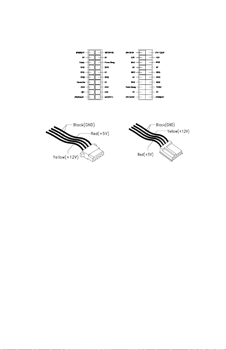
Pin-hole side view Cable side vi ew
006 - ARE THE VOLTAGES CORRECT AND DOES THE FAN RUN? (YES,
READ AHEAD. NO, GO TO STEP 009.)
•
The power supply is working normally.
•
If you suspect the on/off switch cable a ssembly, see Step 003.
•
If the fan continues to run when all connectors are plugged back in, go to
See “Undetermined Problems” on page 70.
•
If the fan stops running when a drive connector is plugged back in, go to
“Start” on page 33.
007 - DO YOU HAVE AN OHM READING WHEN THE SWITCH IS
PRESSED AND AN OPEN R E A D I NG WHEN THE SW I T CH IS RELEASED?
(YES, READ AHEAD. NO, GO TO STEP 008.)
•
Replace the on/off switch cable assembly.
008 -
•
Replace the system board.
•
End.
66
 Loading...