

Page 1

Hardware Maintenance Service
for Service Level A
Machine T y pe 2159
and IBM Monitors
2159
Page 2

Page 3

Hardware Maintenance Service
for Service Level A
Machine T y pe 2159
and IBM Monitors
2159
Page 4

Second Edition (October 1996)
The following paragraph does not apply to the United Kingdom or any country
where such provisions are inconsistent with local law: INTERNATIONAL
BUSINESS MACHINES CORPORATION PROVIDES THIS PUBLICATION “AS IS”
WITHOUT WARRANTY OF ANY KIND, EITHER EXPRESS OR IMPLIED,
INCLUDING, BUT NOT LIMITED TO, THE IMPLIED WARRANTIES OF
MERCHANTABILITY OR FITNESS FOR A PARTICULAR PURPOSE. Some states
do not allow disclaimer of express or implied warranties in certain transactions,
therefore, this statement may not apply to you.
This publication could include technical inaccuracies or typographical errors. Changes
are periodically made to the information herein; these changes will be incorporated in
new editions of the publication. IBM may make improvements and/or changes in the
product(s) and/or the program(s) described in this publication at any time.
It is possible that this publication may contain reference to, or information about, IBM
products (machines and programs), programming, or services that are not announced
in your country. Such references or information must not be construed to mean that
IBM intends to announce such IBM products, programming, or services in your
country.
Requests for technical information about IBM products should be made to your IBM
reseller or IBM marketing representative.
Copyright International Business Machines Corporation 1996. All rights
reserved.
Note to U.S. Government Users — Documentation related to restricted rights — Use,
duplication or disclosure is subject to restrictions set forth in GSA ADP Schedule
Contract with IBM Corp.
Page 5

Contents
Notices . . . . . . . . . . . . . . . . . . . . . . . . . . . . . . . . . . vii
Voltage Supply Switch Settings .................... vii
Positionnement du sélecteur de tension ............... viii
Safety Information . . . . . . . . . . . . . . . . . . . . . . . . . . . ix
Safety Notices (Multi-Lingual Translations) .............. x
Laser Compliance Statement ..................... xiv
Federal Communications Commission (FCC) Notice ......... xv
Canadian Department of Communications Compliance Statement .. xvi
Trademarks . . . . . . . . . . . . . . . . . . . . . . . . . . . . . . . . xix
Preface . . . . . . . . . . . . . . . . . . . . . . . . . . . . . . . . . . xxi
General Information . . . . . . . . . . . . . . . . . . . . . . . . . . 1-1
Chapter Description . . . . . . . . . . . . . . . . . . . . . . . . . . . 1-2
Diagnostic Information . . . . . . . . . . . . . . . . . . . . . . . . 1-2
Diagnostic Aids . . . . . . . . . . . . . . . . . . . . . . . . . . . 1-3
Repair Information . . . . . . . . . . . . . . . . . . . . . . . . . . 1-4
Parts/Test Point Locations ..................... 1-4
Safety Inspection Guide ....................... 1-4
Parts Catalog . . . . . . . . . . . . . . . . . . . . . . . . . . . . 1-4
Part Number Index ......................... 1-4
Appendix: Model Configurations and FRU Part Numbers ..... 1-5
Product Description . . . . . . . . . . . . . . . . . . . . . . . . . . . 1-6
Hardware Interfaces . . . . . . . . . . . . . . . . . . . . . . . . . . 1-10
Refresh Rates and Monitor Frequencies .............. 1-11
Power-On Password, CMOS Reset .................. 1-12
Flash (BIOS) Update Procedure .................... 1-13
Setup Utility . . . . . . . . . . . . . . . . . . . . . . . . . . . . . . . 1-14
Using the Setup Utility ........................ 1-14
Making Changes with the Setup Utility ............... 1-16
Using Rapid Resume Manager ..................... 1-22
Rapid Resume Manager Features ................. 1-22
Rapid Resume Connectors ..................... 1-23
POST Error History ........................... 1-24
System Memory . . . . . . . . . . . . . . . . . . . . . . . . . . . . 1-25
SIMM Identification . . . . . . . . . . . . . . . . . . . . . . . . . 1-25
DIMM Identification . . . . . . . . . . . . . . . . . . . . . . . . . 1-25
Specifications . . . . . . . . . . . . . . . . . . . . . . . . . . . . . . 1-26
Operating Requirements . . . . . . . . . . . . . . . . . . . . . . . . 1-27
Special Tools . . . . . . . . . . . . . . . . . . . . . . . . . . . . . . 1-28
Copyright IBM Corp. 1996 iii
Page 6

Check Procedures . . . . . . . . . . . . . . . . . . . . . . . . . . . 2-1
Start . . . . . . . . . . . . . . . . . . . . . . . . . . . . . . . . . . . 2-2
Index of Symptoms, Messages, Error Codes, or Beeps ........ 2-9
Power Supply . . . . . . . . . . . . . . . . . . . . . . . . . . . . . . 2-35
Memory . . . . . . . . . . . . . . . . . . . . . . . . . . . . . . . . . 2-38
Keyboard . . . . . . . . . . . . . . . . . . . . . . . . . . . . . . . . 2-40
Mouse . . . . . . . . . . . . . . . . . . . . . . . . . . . . . . . . . . 2-42
Diagnostics Device Presence Test ................... 2-43
Access Station Drive Devices ..................... 2-46
Factory-Installed Drive Devices .................... 2-47
Diagnostics for Factory-Installed Drive Devices Not Supported by the
Diagnostics CD . . . . . . . . . . . . . . . . . . . . . . . . . . . . 2-50
Diagnostics for Factory-Installed Riser Card, Sound Card, or Adapter
Cards Not Supported by Diagnostics CD ............... 2-53
Mwave Adapter . . . . . . . . . . . . . . . . . . . . . . . . . . . . . 2-59
33.6 Kbps DSVD Factory-Installed Modem Adapter .......... 2-63
Monitor . . . . . . . . . . . . . . . . . . . . . . . . . . . . . . . . . 2-67
Undetermined Problem . . . . . . . . . . . . . . . . . . . . . . . . . 2-69
Diagnostic Aids . . . . . . . . . . . . . . . . . . . . . . . . . . . . 3-1
Introduction . . . . . . . . . . . . . . . . . . . . . . . . . . . . . . . 3-2
Power-On Self Test ........................... 3-2
Diagnostics CD . . . . . . . . . . . . . . . . . . . . . . . . . . . . . 3-3
Creating a Diagnostics Bootable Diskette ............... 3-4
Diagnostic Test Programs ....................... 3-6
Error Messages . . . . . . . . . . . . . . . . . . . . . . . . . . . 3-7
Return Codes . . . . . . . . . . . . . . . . . . . . . . . . . . . . 3-7
Using the Advanced Diagnostic Test Programs ............ 3-8
Program Navigation . . . . . . . . . . . . . . . . . . . . . . . . . 3-8
Viewing the Test Groups ...................... 3-10
Scripting . . . . . . . . . . . . . . . . . . . . . . . . . . . . . . . 3-10
Changing Logical Unit Numbers ................... 3-11
Test Group Specifications ...................... 3-11
Stopping the Tests ......................... 3-13
Formatting Diskettes . . . . . . . . . . . . . . . . . . . . . . . . . 3-13
Hard Disk Drive Boot Error ..................... 3-14
File Editor . . . . . . . . . . . . . . . . . . . . . . . . . . . . . . 3-14
File Edit Function Key Usage .................... 3-14
Diagnostics Control Keys ...................... 3-16
Repair Information . . . . . . . . . . . . . . . . . . . . . . . . . . 4-1
Removals and Replacements—Machine Type 2159 .......... 4-2
2005—Cover . . . . . . . . . . . . . . . . . . . . . . . . . . . . 4-3
2020—3.5-In. Bays . . . . . . . . . . . . . . . . . . . . . . . . . 4-4
iv
Page 7

2025—5.25-In. Bays . . . . . . . . . . . . . . . . . . . . . . . . . 4-5
2030—Hard Disk Drives ....................... 4-6
2032—Access Station . . . . . . . . . . . . . . . . . . . . . . . . 4-8
2035—Adapter Cards . . . . . . . . . . . . . . . . . . . . . . . . 4-9
2040—Power Supply . . . . . . . . . . . . . . . . . . . . . . . . 4-10
2045—Riser Card . . . . . . . . . . . . . . . . . . . . . . . . . . 4-11
2050—Memory (SIMM) . . . . . . . . . . . . . . . . . . . . . . . 4-12
2051—Memory (DIMM) . . . . . . . . . . . . . . . . . . . . . . . 4-13
2055—Cache Memory . . . . . . . . . . . . . . . . . . . . . . . . 4-14
2060—Processor Removal . . . . . . . . . . . . . . . . . . . . . 4-15
2080—Lithium Battery . . . . . . . . . . . . . . . . . . . . . . . . 4-16
2090—System Board . . . . . . . . . . . . . . . . . . . . . . . . 4-17
Handling ESD-Sensitive Parts ..................... 4-18
Home Automation . . . . . . . . . . . . . . . . . . . . . . . . . . . . 4-19
Software Installation Procedure .................... 4-22
Parts/Test Point Locations ...................... 5-1
System Board Layout .......................... 5-2
System Board Locations ...................... 5-3
System Bus Clock .......................... 5-4
Core Bus Frequency Ratio Settings ................. 5-4
Power Supply Cable Connector Specifications ............. 5-5
Mwave Card . . . . . . . . . . . . . . . . . . . . . . . . . . . . . . 5-7
Connectors . . . . . . . . . . . . . . . . . . . . . . . . . . . . . 5-7
Sound Card . . . . . . . . . . . . . . . . . . . . . . . . . . . . . . . 5-8
Factory-Installed Modem Card ..................... 5-9
Hard Disk Drive Jumper Settings .................... 5-10
CD-ROM Drive Jumper Settings .................... 5-13
Access Station . . . . . . . . . . . . . . . . . . . . . . . . . . . . . 5-14
SIMM Configurations . . . . . . . . . . . . . . . . . . . . . . . . . . 5-16
Detachable Monitor I/O Signal Cable Connector Test Points ..... 5-17
System Board Connector Specifications ................ 5-18
Safety Inspection Guide ....................... 6-1
Parts Catalog . . . . . . . . . . . . . . . . . . . . . . . . . . . . . 7-1
Assemblies (Service Level A) ..................... 7-2
Catalog Section . . . . . . . . . . . . . . . . . . . . . . . . . . . . . 7-3
Assembly 1: Machine Type 2159 System Unit - Exterior (SL-A) .. 7-3
Assembly 2: Machine Type 2159 System Unit - Interior (SL-A) .. 7-4
Assembly 3: Diskette and Hard Disk Drives ............ 7-7
Assembly 4: Access Station . . . . . . . . . . . . . . . . . . . . 7-9
Assembly 5: MWave, Host, Sound, and Modem Cards ...... 7-10
Assembly 6: Monitor and Power Cord (Linecord) ......... 7-11
Contents v
Page 8

Assembly 7: Keyboard and Mouse ................. 7-13
Assembly 8: Software . . . . . . . . . . . . . . . . . . . . . . . 7-14
Part Number Index .......................... 8-1
Appendix A. Online Support Information .............. A-1
Appendix B. Model/Monitor Configurations and FRU Part Numbers B-1
Index . . . . . . . . . . . . . . . . . . . . . . . . . . . . . . . . . . X-1
vi
Page 9

Notices
References in this publication to IBM products, programs, or services do not
imply that IBM intends to make these available in all countries in which IBM
operates. Any reference to an IBM product, program, or service is not
intended to state or imply that only IBM’s product, program, or service may
be used. Any functionally equivalent product, program, or service that does
not infringe any of IBM’s intellectual property rights or other legally
protectable rights may be used instead of the IBM product, program, or
service. Evaluation and verification of operation in conjunction with other
products, programs, or services, except those expressly designated by IBM,
are the user’s responsibility.
IBM may have patents or pending patent applications covering subject
matter in this document. The furnishing of this document does not give you
any license to these patents. You can send license inquiries, in writing, to
the IBM Director of Commercial Relations, IBM Corporation, Purchase, NY
10577.
Voltage Supply Switch Settings
Your IBM Aptiva Personal Computer
must be set correctly for your voltage supply. If your monitor or system unit
has a voltage switch, complete these steps to make sure each switch is set
correctly:
1. Determine the correct voltage switch setting for your area:
Voltage Supply
Range
100–127 V 115 V or 115
200–240 V 230 V or 230
2. Locate the voltage switch on the back of your monitor or system unit. If
the setting shown on the switch is:
Correct, start setting up your IBM Aptiva computer.
Incorrect, change the voltage switch setting. (You may need a
small screwdriver.)
Copyright IBM Corp. 1996 vii
might
have voltage switches, which
Voltage Switch
Setting
Page 10

Positionnement du sélecteur de tension
Votre Aptiva IBM
peut
comporter des sélecteurs de tension qui doivent être
positionnés correctement en fonction de la tension adéquate. Si votre écran
ou votre unité centrale sont équipés d’un sélecteur de tension, vérifiez-en le
positionnement en procédant de la manière suivante :
1. Le tableau ci-dessous permet de déterminer le positionnement correct
du ou des sélecteurs de tension :
Positionnement du
Tensions
100–127 V 115 V ou 115
200–240 V 230 V ou 230
sélecteur de tension
2. Repérez le ou les sélecteurs de tension situés à l’arrière de votre écran
ou de votre unité centrale. S’ils sont positionnés de façon :
Correcte, démarrez la configuration de votre Aptiva IBM.
Incorrecte, modifiez leur position. (Vous pouvez vous aider d’un
petit tournevis.)
viii
Page 11

Safety Information
The construction of the IBM Aptiva Personal Computer provides extra
protection against the risk of electrical shock. This computer has a power
cord with a three-prong plug that is required to ground metal parts. It is the
responsibility of the person installing the computer to connect it to a properly
grounded electrical outlet. Seek professional assistance before using an
adapter or extension cord; these devices could interrupt the grounding
circuit.
If the computer is connected to an electrical outlet that is incorrectly
connected to the building wiring, serious electrical shock could result.
For continued protection against the risk of electrical shock:
Connect your computer only to an electrical outlet of the correct voltage.
If you are unsure about the voltage of the electrical outlet you are using,
contact your local power company.
If your computer has cables other than the power cords, you must
connect them before plugging the power cord into an electrical outlet.
Before removing these cables, you must first unplug the power cords
from the outlet.
If your computer has a telephone connection, do not touch the
telephone cords when there is lightning in the area.
Do not use or store the computer in an area where it can become wet.
Make sure all replacement parts have characteristics identical or
equivalent to the original parts. Other parts may not have the same
safety features.
Personal injury or electrical shock may result if you undertake actions
other than those specifically described in this book. This is particularly
true if you try to service or repair the power supply, monitor, or built-in
modem. Always refer service or repairs to qualified service personnel.
Notices ix
Page 12

Safety Notices (Multi-Lingual Translations)
The safety notices in this section are provided in the following languages:
English
Brazilian/Portuguese
Chinese
French
German
Hungarian
Italian
Russian
Slovakian
Spanish
x
Page 13
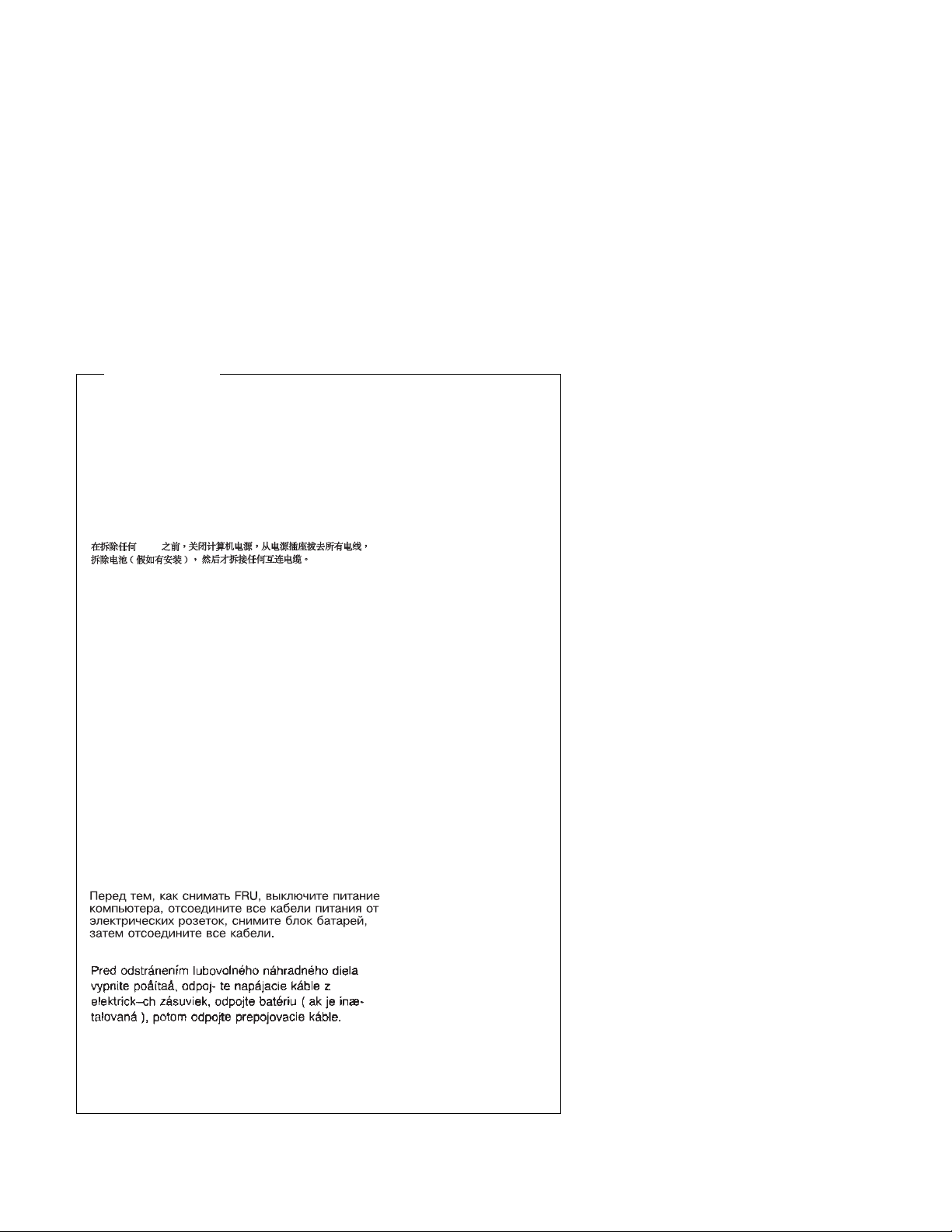
Safety Notice 1
Before removing any FRU, power-off the computer, unplug all power
cords from electrical outlets, then disconnect any interconnecting cables.
Antes de remover qualquer unidade substituível no local (Field
Replaceable Unit - FRU), desligue o computador, retire todos os cabos
de alimentação das respectivas tomadas eléctricas, remremova a pilha
(se instalada) e, em seguida, desconecte todos os cabos de interligação.
FRU
Avant de retirer une unité remplaçable en clientèle, mettez le système
hors tension, débranchez tous les cordons d'alimentation des socles de
prise de courant, retirez la batterie et déconnectez tous les cordons
d'interface.
Die Stromzufuhr muß abgeschaltet, alle Stromkabel aus der Steckdose
gezogen, der Akku entfernt und alle Verbindungskabel abgenommen
sein, bevor eine FRU entfernt wird.
A helyszínen cserélhetõ egységek eltávolítása elõtt
kapcsolja ki a számítógépet, húzza ki a konnektorból
a hálózati csatlakozót, majd távolítsa el az összekötõ
kábeleket is.
Prima di rimuovere qualsiasi FRU, spegnere il sistema, scollegare dalle
prese elettriche tutti i cavi di alimentazione, rimuovere la batteria e poi
scollegare i cavi di interconnessione.
Antes de quitar una FRU, apague el sistema, desenchufe todos los
cables de las tomas de corriente eléctrica, quite la batería y, a
continuación, desconecte cualquier cable de conexión entre dispositivos.
Notices xi
Page 14

Safety Notice 2
The lithium battery can cause a fire, explosion, or severe burn. Do not
recharge it, remove its polarized connector, disassemble it, heat it above
100°C (212°F), incinerate it, or expose its cell contents to water.
Dispose of the battery as required by local ordinances or regulations.
Use only the battery in the appropriate parts listing. Use of an incorrect
battery can result in ignition or explosion of the battery.
A pilha de lítio representa risco de incêndio, explosão ou queimaduras
graves. Não recarregue, desmonte ou exponha a pilha a temperaturas
superiores a 100°C (212°F), não a incinere ou ponha o conteúdo da
respectiva célula em contacto com a água nem remova o respectivo
conector polarizado. Destrua a pilha de acordo com as normas ou
regulamentações locais. Utilize apenas a pilha com o "part-number"
indicado nas listas apropriadas. A utilização de uma pilha incorrecta
pode resultar na igniçãou explosão da mesma.
100 C (212 F)
Elle présente des risques d'incendie, d'explosion ou de brûlures graves.
Ne la rechargez pas, ne retirez pas son connecteur polarisé et ne la
démontez pas. Ne l'exposez pas à une temperature supérieure à
100°C, ne la faites pas brûler et n'en exposez pas le contenu à l'eau.
Mettez la pile au rebut conformément à la réglementation en vigueur.
Une pile inappropriée risque de prendre feu ou d'exploser.
Die Systembatterie ist eine Lithiumbatterie. Sie kann sich entzünden,
explodieren oder schwere Verbrennungen hervorrufen. Batterien dieses
Typs dürfen nicht aufgeladen, zerlegt, über 100 C erhitzt oder verbrannt
werden. Auch darf ihr Inhalt nicht mit Wasser in Verbindung gebracht
oder der zur richtigen Polung angebrachte Verbindungsstecker entfernt
werden. Bei der Entsorgung die örtlichen Bestimmungen für Sondermüll
beachten. Beim Ersetzen der Batterie nur Batterien des Typs
verwenden, der in der Ersatzteilliste aufgeführt ist. Der Einsatz falscher
Batterien kann zu Entzündung oder Explosion führen.
xii
Page 15

Safety Notice 2 Continued
A lítiumelemek meggyulladhatnak, tûz- és robbanásveszélyesek. Ezért ne próbálkozzon az elemek újratöltésével, a csatlakozók eltávolításával, ne kísérletezzen a széjjelszedésükkel ! Óvja õket a 100°C (212°F)
fölötti hõmérséklettõl, ne dobja õket tûzbe, és vigyázzon,
hogy az elemek cellái ne érintkezhessenek vízzel !
A használt elemeket a helyi hatósági rendelkezéseknek
megfelelõen kezelje.
La batteria di supporto e una batteria al litio e puo incendiarsi, esplodere
o procurare gravi ustioni. Evitare di ricaricarla, smontarne il connettore
polarizzato, smontarla, riscaldarla ad una temperatura superiore ai 100
gradi centigradi, incendiarla o gettarla in acqua. Smaltirla secondo la
normativa in vigore (DPR 915/82, successive disposizioni e disposizioni
locali). L'impiego di una batteria non adatta potrebbe determinare
l'incendio o l'esplosione della batteria stessa.
La bateria de repuesto es una bateria de litio y puede provocar
incendios, explosiones o quemaduras graves. No la recargue, ni quite el
conector polarizado, ni la desmonte, ni caliente por encima de los 100°C
(212°F), ni la incinere ni exponga el contenido de sus celdas al agua.
Deséchela tal como dispone la normativa local.
Notices xiii
Page 16

Laser Compliance Statement
Some IBM Personal Computer models are equipped from the factory with a
CD-ROM drive. CD-ROM drives are also sold separately as options. The
CD-ROM drive is a laser product. The CD-ROM drive is certified in the U.S.
to conform to the requirements of the Department of Health and Human
Services 21 Code of Federal Regulations (DHHS 21 CFR) Subchapter J for
Class 1 laser products. Elsewhere, the drive is certified to conform to the
requirements of the International Electrotechnical Commission (IEC) 825 and
CENELEC EN 60 825 for Class 1 laser products.
When a CD-ROM drive is installed, note the following.
CAUTION: Use of controls or adjustments or performance of
procedures other than those specified herein might result in hazardous
radiation exposure.
Opening the CD-ROM drive might result in exposure of hazardous laser
radiation. There are no serviceable parts inside the CD-ROM drive.
Some CD-ROM drives might contain an embedded Class 3A laser
diode. Note the following.
DANGER
Laser radiation when open. Avoid direct eye exposure.
CAUTION: Laser radiation when open. Do not stare into beam or
view directly with optical instruments.
Some CD-ROM drives might contain an embedded Class 3B laser
diode. Note the following.
DANGER
Laser radiation when open. Avoid direct exposure to
beam.
CAUTION: Laser radiation when open. Avoid exposure to beam.
xiv
Page 17

Federal Communications Commission (FCC) Notice
The following statement applies to this IBM product. The statement for other
IBM products intended for use with this product will appear in their
accompanying manuals.
Federal Communications Commission (FCC)
Statement
Note: This equipment has been tested and found to comply with the limits
for a Class B digital device, pursuant to Part 15 of the FCC Rules. These
limits are designed to provide reasonable protection against harmful
interference in a residential installation. This equipment generates, uses,
and can radiate radio frequency energy and, if not installed and used in
accordance with the instructions, may cause harmful interference to radio
communications. However, there is no guarantee that interference will not
occur in a particular installation. If this equipment does cause harmful
interference to radio or television reception, which can be determined by
turning the equipment off and on, the user is encouraged to try to correct the
interference by one or more of the following measures:
Reorient or relocate the receiving antenna.
Increase the separation between the equipment and receiver.
Connect the equipment into an outlet on a circuit different from that to
which the receiver is connected.
Consult an IBM authorized dealer or service representative for help.
Properly shielded and grounded cables and connectors must be used in
order to meet FCC emission limits. Proper cables and connectors are
available from IBM authorized dealers. IBM is not responsible for any radio
or television interference caused by using other than recommended cables
and connectors or by unauthorized changes or modifications to this
equipment. Unauthorized changes or modifications could void the user's
authority to operate the equipment.
This device complies with Part 15 of the FCC Rules. Operation is subject to
the following two conditions: (1) this device may not cause harmful
interference, and (2) this device must accept any interference received,
including interference that may cause undesired operation.
Notices xv
Page 18

Canadian Department of Communications
Compliance Statement
This equipment does not exceed Class B limits per radio noise emissions for
digital apparatus, set out in the Radio Interference Regulation of the
Canadian Department of Communications.
Avis de conformité aux normes du ministère des
Communications du Canada
Cet équipement ne dépasse pas les limites de Classe B d'émission de bruits
radioélectriques pour les appareils numériques, telles que prescrites par le
Règlement sur le brouillage radioélectrique établi par le ministère des
Communications du Canada.
Canadian Department of Communications Certification Label
Notice: The Canadian Department of Communications label identifies
certified equipment. This certification means that the equipment meets
certain telecommunications network protective, operational and safety
requirements. The Department does not guarantee the equipment will
operate to the user’s satisfaction.
Before installing this equipment, users should ensure that it is permissible to
be connected to the facilities of the local telecommunications company. The
equipment must also be installed using an acceptable method of connection.
In some cases, the company’s inside wiring associated with a single line
individual service may be extended by means of a certified connector
assembly (telephone extension cord). The customer should be aware that
compliance with the above conditions may not prevent degradation of
service in some situations.
Repairs to certified equipment should be made by an authorized Canadian
maintenance facility designated by the supplier. Any repairs or alterations
made by the user to this equipment, or equipment malfunctions, may give
the telecommunications company cause to request the user to disconnect
the equipment.
Users should ensure for their own protection that the electrical ground
connections of the power utility, telephone lines and internal water pipe
system, if present, are connected together. This precaution may be
particularly important in rural areas.
xvi
Page 19

Attention
Users should not attempt to make such connections themselves, but
should contact the appropriate electric inspection authority, or electrician,
as appropriate.
Étiquette d'homologation du ministère des Communications du
Canada
AVIS : L'étiquette du ministère des Communications du Canada identifie le
matériel homologué. Cette étiquette certifie que le matériel est conforme à
certaines normes de protection, d'exploitation et de sécurité des réseaux de
télécommunications. Le ministère n'assure toutefois pas que le matériel
fonctionnera à la satisfaction de l'utilisateur.
Avant d'installer ce matériel, l'utilisateur doit s'assurer qu'il est permis de le
raccorder aux installations de l'entreprise locale de télécommunications. Le
matériel doit également être installé en suivant une méthode acceptée de
raccordement. L'abonné ne doit pas oublier qu'il est possible que la
conformité aux conditions énoncées ci-dessus n'empêchent pas la
dégradation du service dans certaines situations.
Les réparations de matériel homologué doivent être effectuées par un centre
d'entretien canadien autorisé désigné par le fournisseur. La compagnie de
télécommunications peut demander à l'utilisateur de débrancher un appareil
à la suite de réparations ou de modifications effectuées par l'utilisateur ou à
cause d'un mauvais fonctionnement.
Pour sa propre protection, l'utilisateur doit s'assurer que tous les fils de mise
à la terre de la source d'énergie électrique, des lignes téléphoniques et des
canalisations d'eau métalliques, s'il y en a, sont raccordés ensemble. Cette
précaution est particulièrement importante dans les régions rurales.
Attention
L'utilisateur ne doit pas tenter de faire ces raccordements lui-même, il
doit avoir recours à un service d'inspection des installations électriques
ou à un électricien, selon le cas.
Notices xvii
Page 20

Load Number (LN):
device denotes the percentage of the total load to be connected to a
telephone loop which is used by the device, to prevent overloading. The
termination on a loop may consist of any combination of devices subject only
to the requirement that the total of the load of all the devices does not
exceed 100. The load number of the built-in modem is 10.
Indice de charge (IC):
dispositif terminal indique, pour éviter toute surcharge, le pourcentage de la
charge totale qui peut être raccordé à un circuit téléphonique bouclé utilisé
par ce dispositif. L'extrémité du circuit bouclé peut consister en n'importe
quelle combinaison de dispositifs pourvu que la somme des INDICES DE
CHARGE de l'ensemble des dispositifs ne dépasse pas 100. L'indice de
charge du modem intégré est de 10.
The load number (LN) assigned to each terminal
L'INDICE DE CHARGE (IC) assigné à chaque
xviii
Page 21

Trademarks
The following terms are trademarks or service marks of IBM Corporation in
the United States and other countries.
Aptiva
AT
HelpCenter
IBM
Mwave
Operating System/2
OS/2
Personal System/2
PS/1
PS/2
Rapid Resume
SurePath
The following terms are trademarks or service marks of other companies as
follows:
America Online America Online, Inc.
APM Astek International Ltd.
Aria Prometheus Products, Inc.
ATI ATI Technologies, Inc.
CompuServe CompuServe Incorporated
Intel Intel Corporation
Microsoft Microsoft Corporation
MS Microsoft Corporation
OverDrive Intel Corporation
Pentium Intel Corporation
QAPlus/PRO DiagSoft, Inc.
Radio Shack Technology Properties, Inc.
Sound Blaster Creative Labs, Inc.
Triplett Triplett Corporation
VESA Video Electronics Standards Association
VL-Bus Video Electronics Standards Association
Zip Iomega Corporation
UNIX is a registered trademark in the United States and other countries
licensed exclusively through X/Open Company Limited.
Microsoft and Windows are trademarks or registered trademarks of Microsoft
Corporation.
Other company, product, and service names, which may be denoted by a
**
double asterisk (
Notices
), may be trademarks or service marks of others.
xix
Page 22

xx
Page 23

Preface
This manual is intended to be used as a stand-alone document to service
this product. It is divided into the following chapters:
“General Information” contains a brief description of this manual.
“Check Procedures” provides step-by-step instructions that aid in
locating the failing Field Replaceable Unit (FRU).
“Diagnostic Aids” explains the diagnostic aids that are available for
troubleshooting problems on the system unit.
“Repair Information” contains the procedures for removing FRUs.
“Parts/Test Point Locations” contains illustrations of the locations of
the major parts and connectors.
“Safety Inspection Guide” contains information about inspecting a
machine for safety problems before putting the machine under a
Maintenance Agreement.
“Parts Catalog” contains descriptions, illustrations, and part numbers
for individual FRUs.
Appendix A, “Online Support Information” contains online support
information.
“Part Number Index” contains part numbers listed in numerical order.
Appendix B, “Model/Monitor Configurations and FRU Part
Numbers” contains models and FRUs listed by part number for all
countries.
Copyright IBM Corp. 1996 xxi
Page 24

xxii
Page 25

General Information
Chapter Description . . . . . . . . . . . . . . . . . . . . . . . . . . . 1-2
Diagnostic Information . . . . . . . . . . . . . . . . . . . . . . . . 1-2
Diagnostic Aids . . . . . . . . . . . . . . . . . . . . . . . . . . . 1-3
Repair Information . . . . . . . . . . . . . . . . . . . . . . . . . . 1-4
Parts/Test Point Locations ..................... 1-4
Safety Inspection Guide ....................... 1-4
Parts Catalog . . . . . . . . . . . . . . . . . . . . . . . . . . . . 1-4
Part Number Index ......................... 1-4
Appendix: Model Configurations and FRU Part Numbers ..... 1-5
Product Description . . . . . . . . . . . . . . . . . . . . . . . . . . . 1-6
Hardware Interfaces . . . . . . . . . . . . . . . . . . . . . . . . . . 1-10
Refresh Rates and Monitor Frequencies .............. 1-11
Power-On Password, CMOS Reset .................. 1-12
Flash (BIOS) Update Procedure .................... 1-13
Setup Utility . . . . . . . . . . . . . . . . . . . . . . . . . . . . . . . 1-14
Using the Setup Utility ........................ 1-14
Making Changes with the Setup Utility ............... 1-16
Using Rapid Resume Manager ..................... 1-22
Rapid Resume Manager Features ................. 1-22
Rapid Resume Connectors ..................... 1-23
POST Error History ........................... 1-24
System Memory . . . . . . . . . . . . . . . . . . . . . . . . . . . . 1-25
SIMM Identification . . . . . . . . . . . . . . . . . . . . . . . . . 1-25
DIMM Identification . . . . . . . . . . . . . . . . . . . . . . . . . 1-25
Specifications . . . . . . . . . . . . . . . . . . . . . . . . . . . . . . 1-26
Operating Requirements . . . . . . . . . . . . . . . . . . . . . . . . 1-27
Special Tools . . . . . . . . . . . . . . . . . . . . . . . . . . . . . . 1-28
Copyright IBM Corp. 1996 1-1
Page 26

Chapter Description
This chapter contains general information about the contents of this manual,
product descriptions, and other information useful when servicing the
product.
Diagnostic Information
The diagnostic information contains the check procedures you use to
diagnose and isolate product failures. Diagnostic information consists of:
Start:
This is the starting point for any diagnostic action. Based on
high-level symptoms, the information in this check procedure directs
you to more detailed procedures to help you resolve the machine
failure.
Symptoms, Messages, Error Codes, and Beeps:
The Index of Symptoms, Messages, Error Codes, or Beeps lists
symptoms and their probable causes, and directs you to the applicable
check procedures to help you resolve the machine failure. The index
also lists which FRU is the likely cause of the problem.
Check Procedures:
When the Start check procedure sends you to a specific check
procedure or the Index of Symptoms, Messages, Error Codes, or
Beeps, turn to that section and perform the steps as instructed. If
there are any notes or instructions at the top of the page, read them
before you start the procedure.
Carefully read each step of the check procedure and perform the
appropriate action as instructed. If you do not remember the location
of a specific part or test point, or if you do not remember an
adjustment or removal procedure, see the chapter with that
information. Always return to the check procedure after you do this.
In some cases, you are sent to other check procedures to find the
failure.
Diagnostic Aids:
The Diagnostic Aids chapter contains additional information to help
you diagnose a failure of a specific part.
1-2
Page 27

Using the Check Procedures
Failing Parts or Assemblies:
trace a problem to one part or assembly. The last step of the specific check
procedure you are using indicates that a part or assembly is failing. You
should inspect the part or assembly before you decide to replace it. It might
be loose, dirty, or in need of a small repair. The check procedures might
lead you to two, or even three, possible failing parts or assemblies. The
parts that might be failing are listed in order of the most probable failure.
Measuring Voltages:
voltages on cable plugs and electronic board connectors. If you are asked
to measure voltage at several places on a plug or connector, a chart next to
or near the instruction indicates the number of the plug or connector, the pin
numbers you should measure, the signal name, and the correct voltage for
the condition you are measuring. Measure the voltage only at the pins listed
in the chart. Remember to set the meter on the correct scale and to put the
meter leads in the correct position for the voltage you are asked to measure.
Note: Use frame ground for the ground reference. Attach the black meter
(ground) lead to frame ground, except where specified otherwise.
Many check procedure steps instruct you to measure
The check procedures generally help you
Diagnostic Aids
This chapter contains information outside the check procedures to help you
diagnose a failure of a specific part. Some diagnostic aids are resident in
the machine, such as the Power-On Self Test (POST). The machine
performs the POST each time it is powered on. Use this information
throughout the diagnostic procedures. You should become familiar with the
POST and be able to determine if the machine performed all the steps.
POST:
unit is powered on (when Rapid Resume is enabled, a shorter version of
POST is initiated—see “Rapid Resume” on page 1-17). The POST is a
series of system checks and initializations that verify the correct operation of
the base system. Two classifications of malfunctions might be detected
during the POST: critical and noncritical.
Critical malfunctions
incorrect results that are apparent to the user. Examples of critical errors
include processor or interrupt controller malfunctions. If a critical error is
detected during the POST, an attempt is made to indicate the error, and all
testing halts.
General Information 1-3
The normal POST is initiated automatically each time the system
prevent the system from operating at all, or could cause
Page 28

Noncritical malfunctions
the user. An example of a noncritical error is a memory module failure. If a
noncritical error occurs, an error code is displayed, and the testing is
stopped. Testing can be continued on a noncritical error by pressing the
Esc key.
After a successful POST (one in which no critical errors were detected), a
single short beep is generated. The system attempts to load an operating
system. The system can be customized for different start (boot) methods.
The system’s default startup sequence automatically looks for the operating
system files on the hard disk if the files are not found on diskette.
Note: Remember that the POST does not test all areas, but only those that
allow the system to operate well enough to run the Diagnostics program.
cause incorrect results that might not be apparent to
Repair Information
This chapter contains removal and replacement instructions.
Parts/Test Point Locations
This chapter contains system board layouts and jumper settings. It is useful
when you are asked to measure voltages. Use this information to help you
locate parts such as electronic boards, connectors, pin numbers, and test
points. This chapter also contains jumper and dual in-line package (DIP)
switch settings for modems, and jumper settings for the hard disk drive,
CD-ROM (compact disc–read-only memory) drive, and sound adapter card.
Safety Inspection Guide
This chapter contains guidelines to help you identify possible safety
concerns. Use this information to inspect a machine for safety problems
before putting the machine under a Maintenance Agreement.
Parts Catalog
This catalog includes figures, part numbers, and part names. It also
contains detailed system board descriptions.
Part Number Index
This chapter contains part numbers listed in numerical order.
1-4
Page 29

Appendix: Model Configurations and FRU Part
Numbers
This appendix contains tables, listed by country, of models and FRU part
numbers. Refer to this when ordering FRUs or to determine the part number
of the system board or SIMM installed in the machine you are servicing.
General Information 1-5
Page 30

Product Description
This manual contains service information for the Service Level A (SL-A)
model of the IBM Aptiva Personal Computer, for the U.S., Canada, and
Japan.
The Machine Type 2159 contains slots for seven adapter cards and bays for
eight input/output devices (drives).
For FRU parts information, see the Appendix B, “Model/Monitor
Configurations and FRU Part Numbers” on page B-1.
VESA Local Bus Note:
to the Video Electronics Standards Association (VESA) VL-Bus Specification
2.0 (32 bit). Local bus adapter cards vary in degree of adherence to this
standard. Therefore, IBM cannot guarantee that all available local bus
option cards will perform according to manufacturer’s claims.
This computer will support Internal or External video, but not both
simultaneously.
Security:
on page 1-12.
Power-on password. See “Power-On Password, CMOS Reset”
System Boards:
board jumper and connector locations.
The system board supports Pentium processors and has the following
features:
P54C socket 7-ZIF connector. You must remove the old processor to
install an upgrade processor.
16 KB internal cache memory, and also supports an optional 256 KB or
512 KB external cache modules.
2 MB Video DRAM soldered on the system board.
Four, 72-pin system memory module sockets support these memory
modules:
– 4 MB, 8 MB, 16 MB, or 32 MB SIMM modules.
– Parity (36 bit) or Non-Parity (32 bit) memory SIMMs.
– Memory speed of 60 nanoseconds (ns).
– Tin-lead contacts.
– Fast page mode or extended data out (EDO).
– Dynamic Random Access Memory (DRAM).
The VESA local bus connector generally conforms
See “System Board Layout” on page 5-2 for system
1-6
Page 31

One, 168-pin Gold, EDO, 60 ns, Parity or Non-Parity DIMM module.
Depending on model, 16 MB or 32 MB of system memory is supplied.
Maximum system board memory is 128 MB. Refer to “System Memory”
on page 1-25 and to “SIMM Configurations” on page 5-16.
Ports: serial, USB (Universal Serial Bus), parallel, keyboard, mouse,
and video.
Connectors for:
– PCI/ISA riser card (212-pin)
– VESA Video Feature (2x20 un-shrouded)
– Input power (12-pin)
– AT diskette drives (34-pin)
– Two 40-pin Enhanced IDE drive controllers: a primary local bus
IDE that supports two hard disk drives and a secondary Enhanced
IDE that supports a CD-ROM drive and one hard disk drive, or two
hard disk drives.
Note: Enhanced IDE for the Type A system board supports up to
Mode 4. Mode 1, 2, 3, 4, etc. are the progressive industry levels
for Enhanced IDE.
Power light-emitting diode (LED)/hard disk LED (4-pin)
12 volt supply for external speakers
Power-on switch 2-wire connector and a power supply auxiliary control
3-wire connector for Rapid Resume features.
Wake Up on Ring connector for Rapid Resume automatic wake-up
features.
Lithium battery.
Processors
One of the following processors can be installed:
Pentium P54C-133 MHz internal; 66 MHz external
Pentium P54C-150 MHz internal; 60 MHz external
Pentium P54C-166 MHz internal; 66 MHz external
Pentium P54C-200 MHz internal; 66 MHz external
Pentium P55C-166 MHz internal; 66 MHz external
Pentium P55C-200 MHz internal; 66 MHz external
General Information 1-7
Page 32

Power Supplies (with Rapid Resume Features)
The power supply is a 145-W switchable high/low voltage power supply
with a variable fan speed and a connector for a detachable grounded
3-wire power cord. The power cable has four DASD connectors: one
mini power connector and three standard 4-pin connectors. The power
supply also has a non-switched appliance outlet connector.
For some countries outside the United States, the power supply might
have five standard 4-pin connectors and one mini power connector, for
a total of six DASD connectors.
To support the Rapid Resume feature, all power supplies have a 3-wire
auxiliary control cable that connects to the system board. There is no
on/off switch cable assembly for the power supplies.
Cables
All models contain one cable for hard disk drives and one cable for
diskette drives. A Wake Up on Ring modem cable, and a voice modem
cable are also included.
Diskette Drive—AT-type
All models contain a 3.5-in. 1.44 MB slimline diskette drive.
Multimedia
5.25-in. high-performance, eight-speed (8X) CD-ROM IDE/AT drive that
can read data and play audio from standard and mini CD-ROM and
audio compact discs (audio CDs). It is compatible with
industry-standard multimedia requirements.
An audio cable
Sound adapter card (on some models)
Mwave card with fax send/receive, telephone answering, speakerphone,
wavetable audio, voice-over-data, and 3D sound features (on some
models).
A CD-ROM drive system interface cable.
One pair of speakers integrated into monitor.
Microphone integrated into monitor.
Joystick (on some models).
Hard Disk Drive
The hard disk drive is a 3.5-in. slimline IDE AT drive with “look-ahead”
cache memory and a minimum of 14 ms average access time. Access
time varies by the hard disk drive and the hard disk drive manufacturer.
1-8
Page 33

Monitors
Multimedia Monitors include:
– .28-mm dot pitch multi-scanning, non-interlaced VGA, 800x600 and
1024x768 modes. These can also be configured to run in
interlaced mode.
– Power switch. Monitors are rated as Power Saver monitors that
reduce power consumption when Rapid Resume is enabled. See
“Parts Catalog” on page 7-1 for FRU part numbers.
– Up to eleven user controls: horizontal position, vertical position,
brightness, contrast, horizontal size, vertical size. speaker volume,
side pincushion, and trapezoidal control, Pin corner, pin balance,
and parallelogram control available on some models.
– Connector for a detachable grounded 3-wire power cord.
– Integrated stereo amplifier and speakers.
– Internal microphone.
– Provision for external headphone and microphone connections.
– 1.5-m (4.9-ft) attached signal cable (detachable on some models).
– Single voltage input.
Keyboard
101-key, 102-key, or 104-key rubber dome enhanced keyboard with
1.8-m (6-foot) cable.
Mouse
Mouse with 1.8-m (6-foot) cable
Remote mouse available on some models.
General Information 1-9
Page 34

Hardware Interfaces
The following peripheral interfaces for adapters, options, and drives are
supported in the system unit.
Table 1-1. Hardware Interfaces
Item Interface
Hard disk drives Enhanced IDE mode 4 local bus interface (American
National Standards Institute–ANSI)
Input/output (I/O)
adapter cards
Diskette drives AT diskette interface
Video For refresh rates and monitor frequency settings, see
Serial 9-pin connector with RS232D electrical interface
USB Universal Serial Bus. High speed serial bus designed
Parallel Bidirectional. ECP bidirectional and EPP bidirectional
Pointing device IBM PS/2-compatible mouse
Keyboard device IBM PS/2-compatible enhanced keyboard
CD-ROM drive AT IDE, extended architecture (XA) enabled drive
Sound adapter card Combination Modem/Sound Card
Joystick Industry-standard device
Adapters that are IBM AT-ISA compatible and operate
at 8 MHz. PCI local bus adapter cards and Plug and
Play adapter cards are supported.
“Refresh Rates and Monitor Frequencies” on page 1-11.
Physical interface is compatible with the IBM Personal
System/2 (PS/2) VGA interface.
for USB protocol.
interfaces are supported.
1-10
Page 35

Refresh Rates and Monitor Frequencies
This section provides the refresh rates and monitor frequencies the system
board.
Refresh Rates and Monitor Frequencies
The following table lists the maximum vertical refresh rates for the system
board that contains a ATI-MACH64 video chip with 2 MB of video DRAM.
Table 1-2. Maximum Vertical Refresh Rates (Hz)
Type A System Board with a ATI-MACH64 Video Chip with 2 MB DRAM
Resolution → 640x480 800x600 1024x768 1280x1024
Color ↓
256 120 Hz. 120 Hz. 120 Hz. 75 Hz.
64,000 120 Hz. 85 Hz. 85 Hz. N/A
16,000,000 90 Hz. 70 Hz. N/A N/A
General Information 1-11
Page 36

Power-On Password, CMOS Reset
A power-on password denies access to the system by an unauthorized user
when the system is powered on. When a power-on password is active, the
password prompt appears on the screen each time the system is powered
on. The system unit starts after the proper password is entered.
In some cases, you might be required to service a system with an active and
unknown power-on password. To clear a password from the system, first
identify the system CMOS jumper by referring to “System Board Layout” on
page 5-2, then follow these steps.
1. Power-off the system unit.
2. Unplug the power cable from the electrical outlet.
Attention: Do not attempt these steps with the power cord plugged into
the electrical outlet. The power supply maintains +5 V dc of auxiliary
power when the power switch is powered off. System damage might
result if the power cord is not unplugged during testing.
3. Locate the power on password jumper on the system board.
System Board Type Jumper
System Board Type A Password Jumper JP12
4. Move the jumper from pins 1-2 to pins 2-3 to erase the password. See
“System Board Layout” on page 5-2.
5. The system detects the change and the password, time, and date are
erased from memory. Rapid Resume settings are also deleted. (See
“Rapid Resume” on page 1-17.)
6. Move the jumper from pins 2-3 to pins 1-2 for normal operation.
7. Plug the power cable into the electrical outlet and power-on the system
unit.
8. Run the Setup Utility to restore the configuration settings. Press Esc to
save with the password disabled.
9. When you are finished servicing the machine, run the Setup Utility to
restore the configuration settings. (You must reset the time, date, and
any Rapid Resume settings. See “Rapid Resume” on page 1-17.)
1-12
Page 37

Notes:
1. To reinstall the password, the user must enter a password in the Setup
Utility.
2. Disabling the power on password reconfigures the system. Run the
Setup Utility to clear any 16X errors.
3. To determine if the machine you are servicing has the Rapid Resume
feature enabled, run the Setup Utility and check to see if Rapid Resume
is enabled on the third screen (Page 3).
Flash (BIOS) Update Procedure
Attention
The system board Flash Enable jumper default position is set to
enabled
Flash Enable jumper is set to the
jumpers by referring to “System Board Layout” on page 5-2.
Also, check the Flash diskette for a README file and if present, review
it for any model-specific information.
. If the following flash procedure does not work, verify that the
enabled
position. See Flash program
1. Power-off the computer.
2. Insert the Flash diskette into diskette drive A.
3. Power-on the computer.
4. Follow the instructions on the screen to complete the flash (BIOS)
update procedure.
5. Machine type and serial number, if required.
General Information 1-13
Page 38

Setup Utility
The Setup Utility lets you view and change important information about the
computer and its hardware.
Using the Setup Utility
You might need to use the Setup Utility in the following situations:
If you add or replace a hardware option (such as a diskette drive, hard
disk drive, or memory module), and you want to verify or make a
change.
To verify a change after removing a hardware option.
If you get an error code and message.
You can also use the Setup Utility to:
Check the computer’s hardware features. For example, you can use
this program to check the amount of memory or the size of the hard disk
in the computer.
Change the computer’s serial and parallel port settings, and the parallel
port mode.
Set up or change a password on the computer.
Change the date and time on the computer.
Reduce the amount of energy the computer uses by setting up the
computer’s Rapid Resume features.
Determine which Plug and Play adapter cards you want configured by
system BIOS.
Starting the Setup Utility
The Setup Utility displays screens that let you view information about how
the computer is set up (called the configuration), or change certain
information on the computer. There are two ways to display the Setup Utility
screen:
When you power the computer on, this symbol appears:
Press F1 while the symbol is displayed to get the Setup Utility screen.
1-14
Page 39

If you have an error, the computer shows a popup window with an error
code and description. Press Enter to get the Setup Utility screen (see
Figure 1-1 on page 1-16).
The Setup Utility screens display the type of information shown here. The
actual screens on the computer might look slightly different, but they operate
the same way.
Here are the keys you use to move through and make changes to the Setup
Utility screens.
Keys Function
↑ ↓ Use these arrow keys to highlight an option.
← → Use these arrow keys to make a selection and change an
option.
F1 Help. Press this key if you want more information about an
option or using the screen.
F2 General Help. Press this key if you want general information
about the computer features.
Page Down Press this key to see the next page (screen).
Page Up Press this key to go to the previous page (screen).
Brackets [ ] show you which options can be changed on the screen.
The * symbol on the screen shows you that an option has been
changed.
Now that you know how to work with the Setup Utility screens, read on to
learn about the options you can change on the screen.
General Information 1-15
Page 40

à ð
--------------------------
Main Menu
------------------------
System Information
Video Information
Disk Drives
Input/Output Ports
Rapid Resume
Startup Options
Model Information
Advanced Options
á
IBM SurePath Setup Utility
Select a Menu:
Plug and Play
Date and Time
ñ
Figure 1-1. Setup Utility Screen
Making Changes with the Setup Utility
You can change only some of the information that appears on the Setup
Utility screen. The information you can change is always enclosed in
brackets like this: [Disabled]. The entries on the screen that you cannot
change provide useful information about the computer and its hardware. For
example, if the mouse is not working or installed incorrectly, the entry will
show if it is disabled or not installed.
Here are the options available on the Setup Utility screens:
System Information:
features. (This is an
Video Information:
This screen provides a summary of the computer
information only
screen and cannot be changed.)
This screen provides information about the installed
video controller and video memory. For more information on monitors,
monitor frequencies, and refresh rates, see “Hardware Interfaces” on
page 1-10.
Disk Drives:
This screen provides information about the installed diskette
drives, hard disk drives, and CD-ROM installed in the computer. Hard Disk
Drive 1 on this screen is the hard disk that came with the computer.
1-16
Page 41

If you add or change a drive, you must select the correct drive type on this
screen. If you are adding a hard disk or CD-ROM to the computer, see
“System Board Layout” on page 5-2. If both a CD-ROM drive and a hard
disk drive are installed, the jumpers on the hard disk drive must be set to
master for the hard drive to appear as Drive 3 on the Setup Utility screen.
The CD-ROM must be set as the slave device. It will appear as Drive 4 on
the screen.
If a hard disk is the only drive attached to the secondary hard disk drive
connector, it appears as Drive 3 on the Setup Utility screen. If two hard
disks are attached to this connector, they appear as Drives 3 and 4 on the
screen.
Input/Output Ports:
This screen allows you to you change the serial and
parallel port addresses. Mouse and keyboard information is also provided
on this screen.
The computer has two serial ports and one parallel port. Each port has a
special address (identifying location) assigned to it. If you add any additional
serial or parallel port adapters, make sure that each port has a different
address.
The serial port A default address is 3F8-IRQ4.
The serial port B default address is 2F8-IRQ3.
The parallel port default address is 3BCh.
Other serial and parallel port addresses are available. However, if you
change an address on this screen, you might also need to make changes to
the software. For instructions on changing the software, see the user’s
guide or online information supplied with the software.
The Parallel Port Mode allows you to change the mode of the parallel port.
The standard mode for the parallel port is the Compatible mode. You can
increase the efficiency of the parallel port by using Enhanced modes with
supporting hardware.
Note: The Enhanced modes use recent technology and are only supported
by newer hardware (such as a printer).
If you change the mode of the parallel port, you might need to make
changes to the supported hardware and its software.
Rapid Resume:
This screen provides information about the Rapid Resume
features. Rapid Resume is an exclusive IBM energy-saving feature with
many useful options. See “Using Rapid Resume Manager” on page 1-22 for
more information.
General Information 1-17
Page 42

Rapid Resume can:
Save the current state of the computer when you power it off. Any
applications or programs open when the computer is powered off will be
open when the computer is powered back on.
Automatically power off the computer when you have not used the
mouse, keyboard, or hard disk for an amount of time you select. If you
have an energy-saving monitor, it will also power off.
Put the computer in a Standby mode to conserve energy when you
have not used the mouse, keyboard, or hard disk for an amount of time
you select.
Reduce the time the computer takes to start up.
Automatically power-on the computer when the phone rings so that the
computer can receive a fax (Wake Up on Ring).
Automatically power-on the computer at a date and time you choose
(Wake Up on Alarm).
The following are the Rapid Resume options you can change:
APM BIOS Mode:
language that runs the computer. The APM BIOS Mode option shows you
the advanced power management (APM) mode that the operating system’s
APM driver should use when it communicates with BIOS. For Microsoft
Windows 95, APM BIOS Mode should be set to 32-Bit Protected.
Note: If you are using the OS/2 operating system, select 16-Bit Protected
for the APM BIOS Mode.
Rapid Resume:
off (Disabled).
Automatic Power Off
that will pass before the computer powers off automatically. For example:
3ð minutes means that if the mouse, keyboard, or hard disk are not used for
30 minutes, the computer powers off automatically. Only energy-saving
monitors will power off automatically with Rapid Resume.
The current state of the computer is saved before the computer powers off.
Any applications or programs open when the computer powers off will be
open when you power the computer back on.
Initialize Adapter Cards
cards are restarted (initialized) when you power-on the computer.
Standby Timer
will pass before the computer starts conserving energy. For example: 15
The Basic Input/Output System (BIOS) is the machine
This screen lets you turn Rapid Resume on (Enabled) or
is the option that allows you to set the amount of time
is the option that indicates whether the adapter
is the option that allows you to set the amount of time that
1-18
Page 43

minutes means that if the mouse, keyboard, and hard disk drive are not
used for 15 minutes, the monitor goes blank and the hard disk drive in the
computer starts using less power.
Note: Only energy-saving monitors power down during standby.
If you are using the Automatic Power Off feature, the time you set for
Standby must be less than the time you set for Automatic Power Off.
Otherwise, the computer will power off before it enters Standby.
Standby Snapshot
computer saved when it enters Standby. If the electricity goes out or the
computer is powered off while in Standby, the computer resumes at the
saved state when you power it back on. Any applications or programs open
when the computer shut down will be open when the power returns.
Monitor mode
of processor installed in the computer. If you see this option, you can
change the power mode used to blank the monitor during Standby. If you
have an energy-saving monitor, the VESA DPMS setting powers the monitor
back on fastest.
Note: Only energy-saving monitors will power down during Standby.
Halt CPU when Idle
Standby. This conserves power without affecting the operation of the
computer.
Wake Up on Ring
on automatically when the phone rings. This is useful if you have a fax
modem and use the computer to receive faxes. To use this feature, you
must have an internal modem that supports Wake Up on Ring, or an
external modem connected to serial port A on the back of the computer.
Note: With Wake Up on Ring, the computer might power-on automatically
when you dial out on a rotary or pulse telephone. If this occurs, disable the
Wake Up on Ring feature and use it only when you know you will have
incoming fax communications.
is the option that allows you to have the state of the
is an option might or might not appear depending on the type
is the option that allows you to halt the CPU during
is the option that allows you to have the computer power
Indicator
constant rate to indicate that the computer answered the phone one or more
times. The Indicator resets when you power the computer on.
Wake Up on Alarm
power-on automatically at a date and time you specify. Choose the date
General Information 1-19
is a Wake Up on Ring feature that makes the power light blink at a
is the option that allows you to have the computer
Page 44

and time in the Alarm Date and Alarm Time fields. If you select Daily Event,
you can set the Alarm Time, but not the Date.
Alarm Date and Time
want the computer to power-on automatically. Enter the date in the format
shown on the screen.
Type the time in 24-hour format. For example:
12 midnight is ðð:ðð
12 noon is 12:ðð
1 p.m. is 13:ðð
Plug and Play:
features. The screen includes the Auto Configure Cards option, and a list of
all Plug and Play adapter cards installed in the computer.
Auto Configure Cards
All Plug and Play adapter cards configured by system BIOS
Only Plug and Play adapter cards required to boot the system
configured by system BIOS
If you have a Plug and Play operating system, the computer might function
better if only the Plug and Play adapter cards required to boot the system
are configured by system BIOS. If you choose to have only the adapter
cards required to boot the system configured by system BIOS, use the
operating system’s Plug and Play utilities to configure the other Plug and
Play cards.
Plug and Play Adapter Cards
cards you have installed in the system unit.
Note: Only the newest operating systems support Plug and Play adapter
cards. See the documentation supplied with the operating system to
determine if it supports Plug and Play adapter cards.
are options that allow you to set the date and time you
This screen provides information about the Plug and Play
is an option that allows you the choice of:
is the option that lists all the Plug and Play
Startup Options:
power-on (startup) sequence. When you power the computer on, it looks for
the operating system files. Use the Startup Sequence option to tell the
computer where to look for these files. The computer can search for these
files on a diskette, an adapter card, a network, or a hard disk.
The system’s startup sequence automatically looks for the operating system
files on the hard disk if the files are not found on diskette.
This screen provides information about the computer
1-20
Page 45

Model Information:
BIOS version level number, and BIOS manufacturing date.
Date and Time:
computer. The changes take effect immediately. Type the date in the
format shown on the screen.
Type the time in 24-hour format. For example:
12 midnight is ðð:ðð
12 noon is 12:ðð
1 p.m. is 13:ðð
Advanced Options:
computer supports.
Security options (power on password, diskette drive, keyboard)
Power On Password
password to restrict the use of the computer. Each time the computer is
powered on, you must enter this password before you can use the
computer. A password can be up to seven characters long (letters,
numbers, or both). Once you create the password, be sure to write it
down and put it in a secure place.
Diskette Drive Access
access.
Operate without Keyboard
keyboard.
Operate without Diskette Drive(s)
diskette drive.
Cache options (cache size, cache state)
This option shows the amount of internal cache memory in the
computer’s processor. You cannot add internal cache memory to the
computer.
Cache memory is special buffer storage that holds frequently used
instructions and data, and works faster than main storage. With cache
memory installed, the applications and programs run faster. You can
disable cache memory to slow down the computer.
ROM shadowing
This feature provides memory boundary information.
Memory options
This feature provides standard and EDO feature information.
PCI card options
This screen provides model number, serial number,
This screen allows you to change the date and time on the
This screen provides the following features that the
is the option that allows you to create a power on
allows you to enable or disable the diskette drive
allows you the enable or disable the
allows you to enable or disable the
General Information 1-21
Page 46

This feature allows you to enable or disable card bus mastering.
Using Rapid Resume Manager
The IBM Aptiva is supplied with special software called Rapid Resume
Manager that makes using the computer easier and more economical.
Rapid Resume Manager Features
The Rapid Resume Manager has the following features:
Rapid Resume:
Remembers all open or running applications when you
power-off the computer. The next time you power-on the computer, the
programs and files will open just as you left them. The Automatic Power Off
option saves energy by turning the computer off after it has not been used
for a period of time that you set.
Standby:
Lets the computer use less energy after it has been inactive for a
period of time that you set.
Scheduler:
Turns on the computer for an activity that you specify, such as
sending a fax.
Wake Up on Ring:
Turns on the computer when the phone rings to let you
receive a fax.
The following table describes the way the computer will normally operate
when one of the Rapid Resume Manager features is enabled. See the
online Aptiva Index for step-by-step instructions for enabling Rapid Resume
Manager features.
Table 1-3 (Page 1 of 2). Rapid Resume Manager Normal Operation
What Happens Explanation
Task List appears after
turning on the computer.
Delay before mouse
works.
Computer waits before
turning off.
This is a normal feature of Rapid Resume. Use the
Task List to return to an application or disable the
Task List in the Rapid Resume options window.
This is normal for the Standby feature of Rapid
Resume. It might take a few seconds.
This is normal. In some cases, it can take up to
several seconds before Rapid Resume saves the
data and turns off the machine.
1-22
Page 47

Table 1-3 (Page 2 of 2). Rapid Resume Manager Normal Operation
What Happens Explanation
Can’t start the computer
from diskette if Rapid
Resume is enabled.
Computer comes on
when the phone rings.
Computer comes on
when you haven’t
pushed the on/off button.
System unit power
indicator light is blinking,
but system unit is turned
off.
After you power-on the computer, press
Ctrl+Alt+Del when you see the Rapid Resume
screen. There might be a slight delay before the
computer restarts.
This is a normal feature of Wake Up on Ring.
Disable Wake Up on Ring in Rapid Resume
Manager or in the Setup Utility.
This is a normal feature of Scheduler. If you don’t
want this to happen, disable Scheduler in Rapid
Resume Manager or Wake Up on Alarm in the
Setup Utility.
This is a normal feature of Wake Up on Ring
enabled with the Ring Indicator option selected. A
fax might be waiting.
Rapid Resume Connectors
The Rapid Resume feature connectors on the system board are one 3-pin
latched connector for the power supply and one 2-pin latched connector for
the power switch and cable assembly. To remove the latched connector,
press in the latch using the tip of a screwdriver to release the connector.
See “System Board Layout” on page 5-2 for connector locations.
Attention: Do not attempt repairs with the power cord plugged into the
electrical outlet. The power supply maintains +5 V dc of auxiliary power
when the power switch is turned off. System damage might result if the
power cord is not unplugged during testing.
General Information 1-23
Page 48
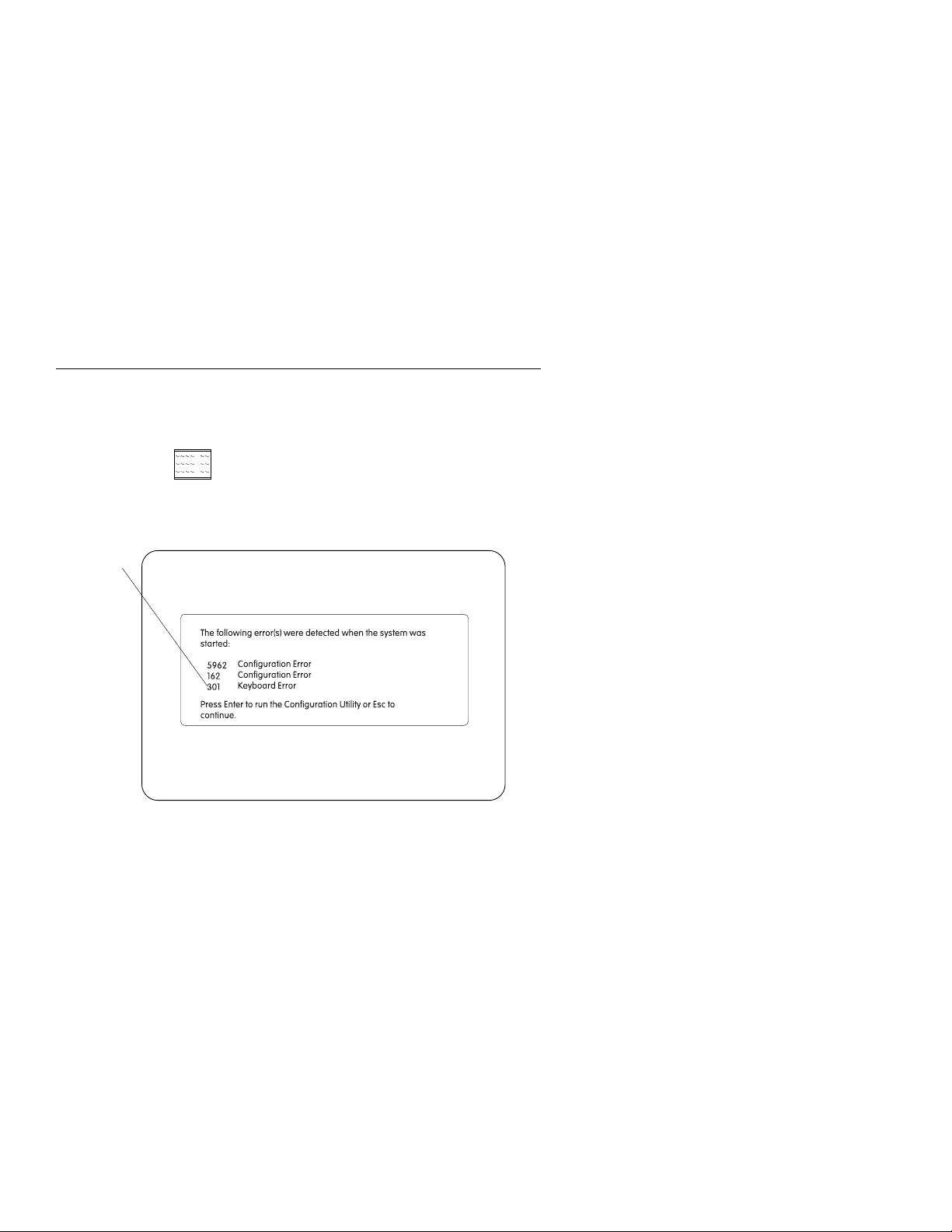
POST Error History
The computer automatically keeps a history of the last three POST errors.
You can access the POST Error History by pressing F9 while the POST
Configuration icon
appears. The POST Error History shows the last
three error codes in a list, with the most recent error code added to the
bottom of the list, as shown in Figure 1-2.
Most recent error
code is listed
at bottom
Figure 1-2. POST Error History
Note: The POST Error History is emptied whenever the password is reset
from the system board or the battery runs out of power. If Rapid Resume is
enabled, press F9 when the memory count and POST Configuration icon
appear.
1-24
Page 49

System Memory
The system board supports 72-Pin, 60 or 70 NS, tin-lead, fast page or EDO,
32 or 36 bit Single Inline Memory Module, (SIMM).
It can also accept a 168-Pin 60 NS, Gold, or EDO, 64 bit Dual Inline
Memory Module, (DIMM). See “SIMM Configurations” on page 5-16 for
installation information.
SIMM Identification
72-pin memory SIMMs are usually marked with a label that shows the size
and speed (for example, 1Mx32, 6ð ns). To determine the SIMM capacity
from the above example, divide 32 bits by 8 bytes and multiply that answer
by 1M, hence, SIMM = 4 MB. 1Mx32 is Non parity and 1Mx36 is Parity.
SIMMs that are not clearly labeled cannot be identified other than by part
number. Consult the SIMM manufacturer documentation to identify SIMMs.
DIMM Identification
168-pin memory DIMMs can usually be identified by the information on the
chip modules. (for example, 2Mx64, 6ð ns, EDO). To determine the DIMM
capacity from the above example, divide 64 bits by 8 bytes and multiply that
answer by 2M, hence, DIMM = 16 MB. 1Mx32 is Non parity and 1Mx36 is
Parity. DIMMs that are not clearly labeled cannot be identified other than by
part number. Consult the DIMM manufacturer documentation to identify
DIMMs.
General Information 1-25
Page 50

Specifications
Size:
Machine Type 2159 system unit
– Width: 241 mm (9.50 in.)
– Depth: 438 mm (17.25 in.)
– Height: 432 mm (17.00 in.)
Monitor Type 7095
– Width: 435 mm (17.1 in.)
– Depth: 424 mm (16.7 in.)
– Height: 349 mm (13.7 in.) with tilt/swivel stand
Monitor Type 7097
– Width: 476 mm (18.7 in.)
– Depth: 438 mm (17.2 in.)
– Height: 418 mm (16.5 in.) with tilt/swivel stand
Weight:
Machine Type 2159 system unit
– 10.9 kg (24 lb)
– If CD-ROM drive installed, 11.8 kg (26 lb)
Monitor
– 14.5 kg (32 lb)
Environment:
Temperature, system unit and monitor
– Power on: 10° to 40°C (50° to 100°F)
– Power off: 1° to 60°C (50° to 104°F)
Humidity, system unit and monitor
– Power on: 8% to 80%
– Power off: 5% to 90%
Maximum altitude: 2134 m (7000 ft)
Heat output:
Machine Type 2159 system unit
– Typical (as shipped): 170 Btu/hr
– Maximum load: 700 Btu/hr
Monitors
– Typical: 323 Btu/hr
– Maximum Load: 375 Btu/hr
1-26
Page 51

Electrical:
Input voltage for system unit and monitor (sinewave input is required)
Low Range
Nominal: 100 V ac to 127 V ac
Maximum: 90 V ac to 132 V ac
High Range
Nominal: 200 V ac to 240 V ac
Maximum: 180 V ac to 259 V ac
Operating Requirements
All machines have two power on switches: one on the system unit and one
on the monitor (if the monitor was shipped with the model). Some high
voltage machines (180–259 V ac) might have a power cord from the
monitor to the system unit and a non-switched appliance connector.
High voltage Northern and Southern Hemisphere SVGA monitors might
come with a voltage selector switch, allowing selection of voltage of either
110 V ac or 220 V ac. This switch must be in the 220 V ac position when
the machine is plugged into a 220 V ac electrical outlet.
When the system unit is powered off for 10 seconds or more and then
powered on, the power supply generates a “power good” signal that resets
the system logic.
Note: Whether or not Rapid Resume is enabled, the on/off switch on the
system unit
appliance outlet connector is always powered on when the system unit is
plugged into an electrical outlet. See “Rapid Resume” on page 1-17 for
more information.
does not
completely power-off the power supply. Also, the
A Note About Energy Saver Monitors
Monitors rated as “Energy Saver” models use 30 W or less when
operating in the energy-saving mode or when the system unit is
powered off.
To extend monitor life, the monitor should be powered off at the end of
each day.
General Information 1-27
Page 52

Special Tools
The following special tools are required to service this system:
A meter similar to the Triplett Model 310 (P/N 9900167)
Wrap plug, P/N 72X8546
Video memory removal tool, P/N 9900764
1-28
Page 53

Check Procedures
Start . . . . . . . . . . . . . . . . . . . . . . . . . . . . . . . . . . . 2-2
Index of Symptoms, Messages, Error Codes, or Beeps ........ 2-9
Power Supply . . . . . . . . . . . . . . . . . . . . . . . . . . . . . . 2-35
Memory . . . . . . . . . . . . . . . . . . . . . . . . . . . . . . . . . 2-38
Keyboard . . . . . . . . . . . . . . . . . . . . . . . . . . . . . . . . 2-40
Mouse . . . . . . . . . . . . . . . . . . . . . . . . . . . . . . . . . . 2-42
Diagnostics Device Presence Test ................... 2-43
Access Station Drive Devices ..................... 2-46
Factory-Installed Drive Devices .................... 2-47
Diagnostics for Factory-Installed Drive Devices Not Supported by the
Diagnostics CD . . . . . . . . . . . . . . . . . . . . . . . . . . . . 2-50
Diagnostics for Factory-Installed Riser Card, Sound Card, or Adapter
Cards Not Supported by Diagnostics CD ............... 2-53
Mwave Adapter . . . . . . . . . . . . . . . . . . . . . . . . . . . . . 2-59
33.6 Kbps DSVD Factory-Installed Modem Adapter .......... 2-63
Monitor . . . . . . . . . . . . . . . . . . . . . . . . . . . . . . . . . 2-67
Undetermined Problem . . . . . . . . . . . . . . . . . . . . . . . . . 2-69
Copyright IBM Corp. 1996 2-1
Page 54

Start
This is the entry point for all check procedures. The check procedures use
failure symptoms, POST error codes, or beeps to help determine the failing
field replaceable unit (FRU). Follow the suggested check procedures or use
the Diagnostics CD to determine the problem FRU.
The Diagnostics program comes on one CD supplied with this book. Use
only this CD for all Service Level A Machine Type 2159 IBM Aptiva
Personal Computers.
The Diagnostics program is intended to test only IBM products. Non-IBM
products, prototype cards, or modified options can give false errors and
invalid system responses.
All voltages in the check procedures are positive unless otherwise shown.
And, use frame ground for all voltage checks unless otherwise specified.
Note: If the check procedures instruct you to replace a FRU and the error
message remains the same, an option adapter card might be causing
the failure. Remove all option adapter cards, one at a time, until the
error changes or the problem is no longer apparent. Replace the last
option adapter card removed.
The hard disk drive contains preloaded software. Refer to “Software
Installation Procedure” on page 4-22 to reinstall the original software. Be
sure to reload the software on the primary hard disk drive (drive C) when
replacing it.
Note: The drives in the system you are servicing might have been
re-arranged or the drive startup sequence changed. Be extremely
careful during write operations, such as copying, saving, or
formatting. Data or programs can be overwritten if you select an
incorrect drive.
Ask the customer to back up any additional software from the
hard disk drive before you take any action.
How to Diagnose Combined FRUs:
more than one FRU, any of the FRUs might cause an error code. Before
replacing the device or adapter, remove the FRUs, one by one, to see if the
symptoms change.
If you have been directed here from another check procedure and were
instructed to replace the system board, and that does not correct the
problem, reinstall the original system board and go through “Start” again.
If an adapter or device consists of
2-2
Page 55

POST Error Codes:
A POST error code can occur in three ways:
1. Under the System Memory count at the upper-left corner of the screen.
Note: A memory error can appear without the memory count as a 203
address error.
2. After two beeps, followed by an error code and/or explanatory message.
3. As a sequence of beeps with no other messages or error codes
displayed.
Note: It might take a minute or more for the system to respond with
error messages or beeps.
If you have an XX62 or XX59 error with no other error codes, run the Setup
Utility (see “Using the Setup Utility” on page 1-14) and note any flagged
options. Note the XX62 error or flagged option and try to add it from the
Configuration/Setup Utility screen. If the option cannot be added, go to
“Index of Symptoms, Messages, Error Codes, or Beeps” on page 2-9 for
additional help.
If you want to print a copy of a Setup Utility screen on an attached printer,
press Print Screen while the screen is displayed.
How to Use Error Messages:
Use the messages, error codes, and beep
combinations that occur to diagnose failures. If more than one failure
occurs, diagnose the first failure first. The cause of the first failure can result
in false messages, error codes, or beeps.
An Access Station failure can cause multiple error codes. For more
information, see “Access Station Drive Devices” on page 2-46. If you did
not receive any messages, error codes, or beeps, see if the symptom is
listed in “Index of Symptoms, Messages, Error Codes, or Beeps” on
page 2-9.
001
To begin this check, note the following:
– To disable or reset the power-on password, see “Power-On Password,
CMOS Reset” on page 1-12.
– Disconnect all external cables and devices from the system unit, except
for the keyboard, mouse, and monitor.
– Power-off the system unit whenever removing or replacing FRUs.
– Remove all adapter cards from the riser card, except for the
factory-installed Mwave card or FAX/modem adapter card and any IBM
Aptiva factory-installed adapter cards.
(Step 001 continues)
Check Procedures 2-3
Page 56

(continued)
001 (continued)
Note: Do not remove the riser card. The system generates multiple error
codes when the riser card is removed and the system is powered on.
– Remove all telephone cables from the Mwave adapter card or modem, if
installed.
– Disconnect any drives except:
3.5-in. diskette drive
Hard disk drive (some machines can have up to 4 hard disk drives
installed.)
IBM Aptiva factory-installed devices (such as a CD-ROM drive).
– Ensure all power cords and cables are connected properly.
– Ensure the monitor brightness and contrast controls are not turned down.
– Ensure the sound volume control is not turned down.
– Power-on the system unit.
Note: Some monitors have a detachable system I/O signal cable
between the monitor and the system unit. In either case, check
the power cord or cable before replacing the unit. See
“Detachable Monitor I/O Signal Cable Connector Test Points” on
page 5-17 for pin identification.
High voltage Northern and Southern Hemisphere monitors might
come with a voltage selector (110 V–220 V) switch. The 145-W
power supply might have a voltage selector (110 V–220 V) switch.
Match the switch to the line voltage.
– Ensure correct monitor refresh rate. See “Refresh Rates and Monitor
Frequencies” on page 1-11.
– Note any symptoms, messages, error codes, or beeps.
– Make sure there are no diskettes or CDs in the drives.
DOES THE SYSTEM COMPLETE POST WITH ONE SHORT BEEP AND
DOES AN IBM APTIVA SOFTWARE SCREEN APPEAR?
Note: If Rapid Resume is enabled, answer this question “No.”
Yes No
002
– If Rapid Resume is enabled, you must disable Rapid Resume in the
Setup Utility, and enable it again upon completion of service.
To disable Rapid Resume without changing the customer settings:
1. Make sure the customer saves and closes any open files.
(Step 002 continues)
2-4
Page 57

002 (continued)
2. Power-off, then power-on the system unit.
3. Press F1 while the POST Configuration icon is displayed.
4. In the Setup Utility Main Menu, select Rapid Resume and press
Enter.
5. Write down the present setting of the APM BIOS Mode (top line of
screen) and press the ← key, if needed, to select Disable in
the APM BIOS Mode field.
Note:
Disabling the APM BIOS Mode will disable Rapid Resume without
changing other customer APM settings.
6. Press Esc to exit the Rapid Resume menu.
7. Press Esc again to exit the screen.
8. Press Enter to save the changes and exit the Setup Utility.
9. Rapid Resume is now disabled.
When service is complete, restore the APM BIOS Mode to its original
setting.
1. Power-on the system unit.
2. Press F1 while the POST Configuration icon is displayed.
3. In the Setup Utility, select Rapid Resume and press Enter.
4. Press the ← key, if needed, to select Enable in the APM BIOS
Mode field.
5. Press Esc to exit the Rapid Resume menu.
6. Press Esc again to exit the screen.
7. Press Enter to save the changes and exit the Setup Utility.
The system is now returned to the APM BIOS Mode customer
setting.
– Go to Step 005 on page 2-6.
003
Insert the Diagnostics CD Service Level A in the CD-ROM drive.
DOES THE SYSTEM LOAD THE ADVANCED DIAGNOSTIC PROGRAM
FROM THE CD-ROM DRIVE WHEN POWERED OFF AND THEN ON?
Yes No
004
– Go to “Factory-Installed Drive Devices” on page 2-47.
005
(Step 005 continues)
Check Procedures 2-5
Page 58

005 (continued)
(From step 002)
DO ANY MESSAGES, ERROR CODES, OR SYMPTOMS APPEAR?
Yes No
006
– Go to Step 008.
007
– Go to “Index of Symptoms, Messages, Error Codes, or Beeps” on
page 2-9.
008
(From step 006)
– If not already inserted, place the Diagnostics CD in the CD-ROM drive.
– Power-off the system unit.
– Power-on the system unit, and check for the following responses:
1. One short beep
2. Readable instructions or Main Menu
DID THE SYSTEM PRODUCE THE BEEP AND READABLE SCREEN?
Yes No
(continued)
009
– Go to “Index of Symptoms, Messages, Error Codes, or Beeps” on
page 2-9.
010
If the keyboard responds incorrectly, go to “Keyboard” on page 2-40.
If the monitor shows problems, such as jittering, shifting, or being out of
focus, go to “Monitor” on page 2-67 and run the Diagnostics tests.
If a message or error code is displayed, go to “Index of Symptoms,
Messages, Error Codes, or Beeps” on page 2-9.
– Select Advanced Diagnostics on the menu.
– Select System Info on the menu.
– Select Hardware Config on the menu.
– Compare the Hardware Configuration Report screen with the actual
devices installed in the system unit.
(Step 010 continues)
2-6
Page 59

010 (continued)
Note: If necessary, remove the cover and visually compare the devices
installed in the system unit to those shown in the Hardware
Configuration Report.
DOES THE HARDWARE CONFIGURATION REPORT CORRECTLY
IDENTIFY THE DEVICES INSTALLED IN THE SYSTEM UNIT?
Yes No
011
– The Hardware Configuration Report shows only those devices
supported by the Diagnostics CD and only factory-installed devices
for the model you are servicing.
– If a device is missing from the list and is not factory installed, refer
to the service manual provided for that device. (Refer to the
Appendix B, “Model/Monitor Configurations and FRU Part Numbers”
on page B-1 to determine the factory-installed devices in the model
you are servicing.)
– If a factory-installed drive device or adapter card is not listed in the
Hardware Configuration Report, go to either “Diagnostics for
Factory-Installed Drive Devices Not Supported by the Diagnostics
CD” on page 2-50 or “Diagnostics for Factory-Installed Riser Card,
Sound Card, or Adapter Cards Not Supported by Diagnostics CD”
on page 2-53.
012
– Select Diagnostics Menu from the menu.
– Select Easy Test Diagnostics from the menu.
DOES THE EASY TEST DIAGNOSTICS FINISH WITHOUT ERROR
CODES?
Yes No
013
– If the last test stops and you cannot continue, first make sure all
switches, power connectors, cables, and jumpers are set correctly
and show the correct voltages and continuity.
– Make note of any messages, error codes, beeps, or new symptoms.
Go to “Index of Symptoms, Messages, Error Codes, or Beeps” on
page 2-9.
014
(Step 014 continues)
Check Procedures 2-7
Page 60

014 (continued)
– The Easy Test Diagnostics did not detect a failure. If the system still
displays a failure:
Check all adapter card jumper settings.
Check all adapter card switch settings.
Check all adapter card cables and connectors for proper installation.
Check Access Station host card for proper installation.
Check Access Station client card and cable for proper installation.
Make sure all of the above are set correctly and show the correct
voltages and continuity. Replace any defective cables or adapter
cards. See “Power Supply” on page 2-35, and “System Board
Layout” on page 5-2.
– Run the Easy Test Diagnostics again.
– If an error or other symptom is displayed, go to “Index of Symptoms,
Messages, Error Codes, or Beeps” on page 2-9.
– If no error can be detected or the symptom is intermittent, go to
“Undetermined Problem” on page 2-69.
(continued)
2-8
Page 61

Index of Symptoms, Messages, Error Codes, or
Beeps
Table 2-1 on page 2-10 lists failure symptoms and possible causes. The
most likely cause is listed first. Make sure you complete all items in the
cause or “Action/FRU” column. When servicing a system, always begin with
“Start” on page 2-2. This index can also be used to help you decide which
FRUs to have available when servicing a system.
If you are unable to correct the problem using this index, go to
“Undetermined Problem” on page 2-69.
Notes:
1. If an error message and incorrect audio response occur, diagnose the
error message first.
2. If you cannot run the Diagnostics tests but did receive a POST error
code, diagnose the POST error message.
3. If you did not receive any error message, look for a description of your
error symptoms in the first part of this index.
4. Check all power supply voltages, switch, and jumper settings before you
replace the system board. Also check the power supply voltages if you
have a system no-power condition. (See “Power Supply” on page 2-35
and “System Board Layout” on page 5-2)
In Table 2-1 on page 2-10, an X in an error code can be any number. If
you are unable to correct the problem using this index, go to “Undetermined
Problem” on page 2-69.
If you observe: Go to:
Symptoms that are not beeps or error codes Page 2-10
Beeps in any combination Page 2-26
Error codes displayed on the screen Page 2-29
Check Procedures 2-9
Page 62

Table 2-1 (Page 1 of 25). POST and Diagnostics Index for
Symptoms, Messages, Error Codes, or Beeps
Symptoms, Messages, Error
Codes, or Beeps
Note: To diagnose a problem, first find the symptom, message, error code, or
beeps in left column. If directed to a check procedure, replace the FRU indicated
in the check procedure. If no check procedure is indicated, the first Action/FRU
listed in right column is the most likely cause.
Address Exceeds the Size of
Your Memory.
An invalid memory address was
entered. Diagnostics Tests
display this message during the
Locate Bad Chips option.
Arithmetic Functions Failed.
An error was detected during the
CPU Test.
Audio software program invoked
but no sound comes out of
speakers, or sound comes out of
one speaker only.
Audio software program does not
initiate in software but CD-ROM
drive works normally.
Base Memory Test Failed.
An error was detected in base
memory.
Blinking cursor only and machine
not working normally.
Action/FRU
Symptoms
Memory SIMM
System Board
Processor
System Board
“Diagnostics for Factory-Installed Riser
Card, Sound Card, or Adapter Cards Not
Supported by Diagnostics CD” on
page 2-53.
Mwave/Sound adapter card connection,
cable, jumpers
Mwave/Sound adapter card volume control
Mwave/Sound adapter card
“Diagnostics for Factory-Installed Riser
Card, Sound Card, or Adapter Cards Not
Supported by Diagnostics CD” on
page 2-53.
Mwave jumper settings
Mwave/Sound adapter card
Memory SIMM
System Board
“Factory-Installed Drive Devices” on
page 2-47.
Diskette drive connection/cable
diskette drive
Access Station host card
Access Station client card
Access Station cable
System board
2-10
Page 63

Table 2-1 (Page 2 of 25). POST and Diagnostics Index for
Symptoms, Messages, Error Codes, or Beeps
Symptoms, Messages, Error
Codes, or Beeps
Boot Sector Unreadable.
A boot sector read error was
detected on the hard disk drive.
Bus Noise Test Failed.
RAM Test detected an error in
the memory bus.
Butterfly Cylinder Access Test
Failed.
Hard Disk Drive Test detected
mismatch between the data read
and the data stored on the drive.
Cannot finish diagnostic test. “Diagnostics Device Presence Test” on
CD-ROM drive LED came on
and stayed on more than 20
seconds before shutting off.
Software asks to install disc.
Software displays a Reading CD
error.
CD-ROM drive LED comes on
when inserting a disc but no
CD-ROM drive icon appears in
the File Manager as Drive D.
CD-ROM drive LED does not
come on when inserting a disc in
the drive when the system is
powered on and the CD-ROM
drive power connector has the
correct voltage.
CD-ROM drive LED does not
come on but CD-ROM drive
works normally.
Action/FRU
Hard Disk Drive
Hard Disk Drive Cable
System Board
Memory SIMM
System Board
Hard Disk Drive
Hard Disk Drive Cable
System Board
page 2-43.
CD is not inserted properly.
CD is damaged.
CD has dirt or foreign material on it.
“Factory-Installed Drive Devices” on
page 2-47.
CD-ROM drive connections/cables/jumpers
CD-ROM drive
Access Station host card
Access Station client card
Access Station cable
“Diagnostics for Factory-Installed Riser
Card, Sound Card, or Adapter Cards Not
Supported by Diagnostics CD” on
page 2-53.
CD-ROM drive
Access Station host card
Access Station client card
Access Station cable
CD-ROM drive
Check Procedures 2-11
Page 64

Table 2-1 (Page 3 of 25). POST and Diagnostics Index for
Symptoms, Messages, Error Codes, or Beeps
Symptoms, Messages, Error
Codes, or Beeps
CD-ROM drive does not load or
eject when the system is
powered on, the LED light is off,
and the eject button is pressed
and held.
CD-ROM drive does not read
data files and no error codes or
messages are displayed.
Cannot read from Drive E.
Retry loading CD message is
displayed with disc loaded in
CD-ROM drive.
Mwave/Sound adapter card
works properly.
CD-ROM drive does not play an
audio disc. Mwave/Sound
adapter card works properly.
CD-ROM drive reads data files.
Clock Stopped.
Real-time clock has stopped
working.
CMOS Clock Test Failed
Time and Date Settings for
CMOS and DOS do not Match.
Action/FRU
“Factory-Installed Drive Devices” on
page 2-47.
CD-ROM drive system connection/cable
CD-ROM drive
Access Station host card
Access Station client card
Access Station cable
Power supply
“Diagnostics for Factory-Installed Drive
Devices Not Supported by the Diagnostics
CD” on page 2-50.
Check with a known good disc and correct
level of software.
CD-ROM drive
Access Station host card
Access Station client card
Access Station cable
“Diagnostics for Factory-Installed Drive
Devices Not Supported by the Diagnostics
CD” on page 2-50.
Audio cable on CD-ROM drive is not
connected to sound adapter card. Check
the audio cable from the CD-ROM drive to
the client card in the Access Station and
the audio cable that is connected from the
system board to the host card. If music can
be heard through headphones plugged into
the sound adapter card jack, replace the
CD-ROM drive. Access Station host card
Access Station client card Access Station
cable
Battery
System Board
Battery
System Board
2-12
Page 65

Table 2-1 (Page 4 of 25). POST and Diagnostics Index for
Symptoms, Messages, Error Codes, or Beeps
Symptoms, Messages, Error
Codes, or Beeps
Communication problem.
Modem function does not work
properly.
Controller Diagnostic Test Failed.
An error was detected while
testing the Hard Disk Controller
(Adapter).
Cylinder 0 errors.
Test detected an error reading
the first cylinder of the hard disk
drive.
Device is Not Ready
Ready the Device...
or
Press Any Key
Diskette drive indicator LED
remains on or does not light
when drive is active.
3.5-in. diskette drive and
CD-ROM do not work.
3.5-in. diskette drive does not
work.
Disk Error Encountered Opening
Output File Press Any Key To
Continue.
Action/FRU
Mwave connection/jumpers
Mwave Wake Up on Ring jumper
connection/cable
Mwave card
Riser Card
System Board
Hard Disk Drive
System Board
Hard Disk Drive
System Board
Ensure the device is powered on.
Replace failing device
Device Adapter
(if installed)
System Board
Diskette drive connection/cable
Diskette drive
Access Station host card
Access Station client card
Access Station cable
System board
Access Station host card
Access Station client card
Access Station cable
“Factory-Installed Drive Devices” on
page 2-47.
Diskette drive
Diskette drive connection/cable
Access Station host card
Access Station client card
Access Station cable
System board
Hard Disk Drive
System Board
Check Procedures 2-13
Page 66

Table 2-1 (Page 5 of 25). POST and Diagnostics Index for
Symptoms, Messages, Error Codes, or Beeps
Symptoms, Messages, Error
Codes, or Beeps
DMA #X Failed
Main Components Test detected
an error while testing the DMA
controller.
DMA Page Register Failed
DMA page register error
Drive (x) Media (y) Mismatch
FAT ID mismatch with installed
drive.
Error in video buffer.
Bad bits.
Video memory test error.
Extended Memory Test Failed.
Extended memory error.
FAX/voice modem function has
no sound output. (Data files are
received normally; sound or
sound adapter card works
correctly.)
FAX function does not receive
data files.
FAX/voice function has no sound
output. (Data files are received
normally; sound adapter card
does not produce sound or
cannot be activated in software.)
Floppy Drive Failed.
Diskette drive(s) failed.
Action/FRU
System Board
System Board
Check diskette and diskette drive capacity.
Diskette Drive
System Board
Video Adapter
System Board
Monitor
Memory SIMM
System Board
Check jumper settings and cable
connections on Mwave card.
Mwave card or sound card
Riser Card
System Board
Mwave jumper settings
Mwave card
Riser Card
System Board
“Diagnostics for Factory-Installed Riser
Card, Sound Card, or Adapter Cards Not
Supported by Diagnostics CD” on
page 2-53.
Mwave card or sound card
Riser Card
System Board
Diskette Drive
System Board
Diskette Drive Cable Access Station host
card Access Station client card Access
Station cable
2-14
Page 67

Table 2-1 (Page 6 of 25). POST and Diagnostics Index for
Symptoms, Messages, Error Codes, or Beeps
Symptoms, Messages, Error
Codes, or Beeps
Hard disk or power-on indicator
LED does not light but machine
functions normally otherwise.
Hard Drives Failed.
Hard Disk Drive test error.
Home Automation failures “Home Automation” on page 4-19
Incorrect DOS version. Ensure you are using DOS version 3.0 or
INT Mask Register Failed.
INT Mask Register error.
Insert a CD message icon
appears when a known good
Diagnostics CD is inserted in the
CD-ROM drive.
Intensity or color varies from left
to right of characters and color
bars.
Action/FRU
Check J26 voltages, with power-on:
J26 Hard Disk
Pin Normal Running
1 +5 V dc 0 V dc
2 +5 V dc +5 V dc
3 +5 V dc +5 V dc
4 0 V dc 0 V dc
Pins 1, 2 = Hard Disk Drive
Pins 3, 4 = Power-on LED
Check voltages at Access Station card,
see “Access Station” on page 5-14.
LED connection/cable assembly
Access Station host card
Access Station client card
Access Station cable
System board
Hard Disk Drive
System Board
higher.
Processor
System Board
Ensure the hard disk drive and CD-ROM
drive are not disabled in the startup
sequence in the Setup Utility.
Hard disk drive preloaded software
CD-ROM drive connection/cable
CD-ROM drive
Access Station host card
Access Station client card
Access Station cable
System board
“Monitor” on page 2-67.
System board
Check Procedures 2-15
Page 68

Table 2-1 (Page 7 of 25). POST and Diagnostics Index for
Symptoms, Messages, Error Codes, or Beeps
Symptoms, Messages, Error
Codes, or Beeps
Invalid Date
Clock/DOS date mismatch.
Invalid Format - Bad Track
error message appears when
trying to format a known-good
diskette.
Incorrect memory size shown or
repeated during POST.
Invalid Time
Clock/DOS time mismatch.
Back-up clock and DOS time of
day settings do not match.
I/O devices cannot be added to
configuration.
Joystick does not respond at all. 1. Ensure the joystick is plugged
Action/FRU
Battery
Battery
System Board
Diskette drive connection/cable
Diskette drive
Access Station host card
Access Station client card
Access Station cable
System board
“Memory” on page 2-38.
Battery
System Board
Diskette drive
Diskette drive connection/cable
CD-ROM drive
CD-ROM drive connection/cable
Access Station host card
Access Station client card
Access Station cable
completely into the joystick/MIDI
adapter plug on the Mwave card or the
sound adapter card and secured with
the screws on the adapter plug.
2. Verify that the software application
used with the joystick has joystick
support.
3. Ensure the joystick is enabled in the
software application. This might
require entering keystrokes or a
configuration utility in the software
application.
If the above steps find no problem, see the
“Joystick does not work correctly” symptom
below.
2-16
Page 69

Table 2-1 (Page 8 of 25). POST and Diagnostics Index for
Symptoms, Messages, Error Codes, or Beeps
Symptoms, Messages, Error
Codes, or Beeps
Joystick does not work correctly
(installation is correct—see
above symptom).
Linear Cylinder Access Test
Failed.
Hard disk drive error.
Logic Function Failed.
CPU Logic test error.
Loopback Error
COM Port Test or Parallel Port
error.
A wrap plug must be installed to
successfully complete these
tests.
Machine works but fails to go
into Rapid Resume mode when
configuration is set with Standby
mode enabled or Rapid Resume
mode enabled.
Main Components Failed.
System board error.
Memory test cannot run at this
location in memory.
Not enough free memory
available to start the memory
test.
Missing QAPlus/PRO Files(s).
One or more diagnostic support
files are missing.
Action/FRU
1. Disable the joystick in the software
application.
2. Enable the mouse as the input device
in the software application.
3. If the mouse works in the software
application, replace the joystick. If the
symptom remains, replace the Mwave
card or the sound adapter card.
4. If the mouse does not work, check the
software application troubleshooting
information provided by the
manufacturer.
Hard Disk Drive
Hard Disk Drive Cable
System Board
Processor
System Board
System Board
Wrap Plug
Software application was fully activated
before on/off switch was pushed. Try
operating Rapid Resume from Microsoft
Windows 95 Program Manager panel.
System Board
Processor
Memory SIMM
System Board
Diagnostic CD
Check Procedures 2-17
Page 70

Table 2-1 (Page 9 of 25). POST and Diagnostics Index for
Symptoms, Messages, Error Codes, or Beeps
Symptoms, Messages, Error
Codes, or Beeps
Monitor problem:
Incorrect colors
No high intensity
Missing, broken, or incorrect
characters
Blank monitor (dark)
Blank monitor (bright)
Distorted image
Unreadable monitor
Other monitor problems
Monitor changing colors. “Monitor” on page 2-67
Monitor problem not listed above
(including blank or illegible
monitor).
Mwave error
Mwave communication or sound
not working
No beep during POST but
computer works correctly.
(System board speaker/beeper
bad.)
Non-system disk or disk error
message appears with a
known-good Advanced
Diagnostics diskette.
No Loop-Back Plug.
Skipping External loopback test.
No wrap plug installed.
No system power, or fan not
running.
Action/FRU
“Monitor” on page 2-67.
I/O monitor signal connection/cable
Monitor
System board
“Monitor” on page 2-67
System board
“Mwave Adapter” on page 2-59
Mwave card
Riser Card
System Board
System board
Diskette drive connection/cable
Diskette drive
Access Station host card
Access Station client card
Access Station cable
System board
Install wrap plug on the serial port, rerun
test.
System Board
“Power Supply” on page 2-35.
Power switch assembly
Power supply
Access Station host card.
Access Station client card
Access Station cable
System board
2-18
Page 71

Table 2-1 (Page 10 of 25). POST and Diagnostics Index for
Symptoms, Messages, Error Codes, or Beeps
Symptoms, Messages, Error
Codes, or Beeps
Not ready.
Printer not on-line or not ready.
No 'type-amatic' repeat.
At least one repeat key must be
tested during this test or an error
will occur. Type-amatic test
error.
Not used by any standard
device.
IRQ is not currently being used
by a non-standard device.
Numeric Proc Failed.
NPU test error.
Parallel Port Failed.
Test Report Summary message.
Parallel port or serial port failure
(system board port).
Pass (N): ** Errors ** Drive (X)
Failed.
Diskette drive read/write test
error.
Pass (N) Drive Not Ready.
Diskette drive door is open or
defective.
Action/FRU
Ready Printer
Printer
Printer Cable
System Board
Keyboard
System Board
System Board
Processor
System Board
System Board
“Diagnostics Device Presence Test” on
page 2-43.
Test using a wrap plug while running
Diagnostics.
Cable/connections
System board
Diskette Drive
Access Station host card
Access Station client card
Access Station cable
System Board
Diskette Drive Cable
Ensure diskette drive is ready.
Diskette Drive
Access Station host card
Access Station client card
Access Station cable
System Board
Diskette Drive Cable
Check Procedures 2-19
Page 72

Table 2-1 (Page 11 of 25). POST and Diagnostics Index for
Symptoms, Messages, Error Codes, or Beeps
Symptoms, Messages, Error
Codes, or Beeps
Pass (N): Drive (X) Write
Protected or Unformatted.
Pass (N): Unknown Media Drive
(X).
Diskette Drive Test error.
Place Hi-density Media in Drive.
Media/drive mismatch.
Printer Failed.
Printer powered-on and ready?
Printer Fault.
Printer powered on and ready?
Printer Not Selected.
Ensure the printer is powered on
and ready.
Printer problems. Refer to the service manual for the printer.
Processor fan does not run when
the power supply fan runs.
Action/FRU
Insert a non-write protected, formatted
diskette into the diskette drive; then rerun
the test.
Diskette Drive
Access Station host card
Access Station client card
Access Station cable
System Board
Diskette Drive Cable
Diskette
Diskette Drive
Access Station host card
Access Station client card
Access Station cable
System Board
Diskette Drive Cable
Diskette
Diskette Drive
Access Station host card
Access Station client card
Access Station cable
System Board
Diskette Drive Cable
Printer
Printer Cable
System Board
Printer
Printer Cable
System Board
Printer
Printer Cable
System Board
With power-on, check the processor fan
connector J1 on system board for +12 V
dc.
Processor fan
System board
2-20
Page 73

Table 2-1 (Page 12 of 25). POST and Diagnostics Index for
Symptoms, Messages, Error Codes, or Beeps
Symptoms, Messages, Error
Codes, or Beeps
Processor speed seems slower. “Memory” on page 2-38.
Program loads from the hard
disk with a known-good CD in
the CD-ROM drive or diagnostics
diskette in the first 3.5-inch
diskette drive (and CD-ROM
drive or diskette drive is enabled
in the Setup Utility).
Program or File
Not Found
Press Any Key
Diagnostics cannot find the
USER(N).COM file.
Program Too Big To Fit In
Memory.
Too many Terminate and Stay
Resident programs in memory.
QAPlus/PRO Cannot Be Re-run
Because Of Error In Relocating
Program.
Diagnostics failed to relocate the
Diagnostics Test programs so
the memory space it resides in
was not tested.
RAM Memory Error in Block n.
Bad bits n.
Memory error.
RAM Test Failed.
Memory error.
Read error on cylinder n.
Hard disk drive format error.
Action/FRU
Cache memory
System board
“Factory-Installed Drive Devices” on
page 2-47.
CD-ROM Drive
Diskette Drive
Access Station host card.
Access Station client card
System Board
Power Supply
Diagnostic CD or diskette
CD-ROM Drive or Diskette Drive Access
Station host card
Access Station client card
Access Station cable
System Board
Reboot the system from the Diagnostic CD.
Diagnostic CD
Memory SIMM
System Board
Memory SIMM
System Board
Memory SIMM
System Board
Hard Disk Drive
System Board
Check Procedures 2-21
Page 74

Table 2-1 (Page 13 of 25). POST and Diagnostics Index for
Symptoms, Messages, Error Codes, or Beeps
Symptoms, Messages, Error
Codes, or Beeps
Read Errors
Diskette drive read error.
Real-time clock is inaccurate. Time set incorrectly by user.
Receive Error.
Serial Port loopback test error.
Refresh Failure.
Diagnostics Test detected an
error while testing the DMA
controller's RAM refresh cycle.
RTC Interrupt Failure.
Diagnostics Test cannot detect
the Real-Time clock interrupt.
Serial Chip Error.
COM Port error, general.
Serial Compare Error.
COM Port error, information
transmitted is not the same as
information received.
Serial Time-out Error.
COM Port error, time interval is
too long between transmitted
and received data.
Serious Memory Error — Diags
Cannot Continue.
Memory Test error.
Some or all keys on keyboard do
not work.
Action/FRU
Diskette
Diskette Drive
System Board
Diskette Drive Cable
RTC battery (if less than 2.8 V dc)
System Board
Serial Port Cable
System Board
Memory SIMM
System Board
System Board
Serial Port Cable
System Board
Serial Port Cable
System Board
Serial Port Cable
System Board
Memory SIMM
System Board
“Keyboard” on page 2-40.
Keyboard
Keyboard connection/cable
Access Station host card
Access Station client card
Access Station cable
System Board
2-22
Page 75

Table 2-1 (Page 14 of 25). POST and Diagnostics Index for
Symptoms, Messages, Error Codes, or Beeps
Symptoms, Messages, Error
Codes, or Beeps
Serial or parallel port device
failure (adapter port).
Sorry You Need A Mouse.
Mouse or mouse driver was not
detected.
Sound adapter card,
factory-installed adapter card, or
Mwave card software gives a
Microsoft Windows 95 error
message after POST
configuration.
Hardware problem occurred.
System fails to load the
Diagnostics and Utilities software
System preloaded software
works correctly.
Action/FRU
“Factory-Installed Drive Devices” on
page 2-47
Test using a wrap plug while running
Diagnostics. Before testing, ensure serial
port A is set to address 3F8 or 3E8,
whichever is not used by the Mwave card
(modem settings: COMM1=3F8,
COMM2=3E8). Set serial port B to address
2F8 or 2E8.
Device
Cable/connections
Alternate adapter
System Board
Riser Card
Mouse
System Board
“Diagnostics for Factory-Installed Riser
Card, Sound Card, or Adapter Cards Not
Supported by Diagnostics CD” on
page 2-53
Sound card, adapter card, or Mwave card
connection/cable
Sound card, adapter card, or Mwave card
jumper settings
Sound card, adapter card, or Mwave card
Make sure the CD-ROM drive or diskette
drive is included in the Setup Utility startup
sequence.
“Factory-Installed Drive Devices” on
page 2-47
CD-ROM drive connection/cable
CD-ROM drive
Diskette drive connection/cable
Diskette drive
Access Station host card
Access Station client card
Access Station cable
System Board
Check Procedures 2-23
Page 76

Table 2-1 (Page 15 of 25). POST and Diagnostics Index for
Symptoms, Messages, Error Codes, or Beeps
Symptoms, Messages, Error
Codes, or Beeps
System Hangs.
Go to “Undetermined Problem”
on page 2-69.
System unit does not turn off
with power switch. (System unit
must be unplugged from
electrical outlet to completely
turn off.)
The Address Exceeds The Size
Of Your Memory.
An invalid memory address was
entered. The Diagnostics Tests
display this message during the
Locate Bad Chips option under
the interact menu if an invalid
memory address was entered at
the "Enter Memory Address Of
Bad Chip" prompt.
That Number is Out Of Range.
An invalid bit number was
entered. Diagnostics Tests
display this message during the
Locate Bad Chips option.
Too Many Errors - Test Aborted.
Too many errors, the Diagnostics
Test cannot continue.
Transmit Error.
Internal or external serial port
loopback test failure.
Video Adapter Failed.
Test Result Summary, displayed
if "Fail" was at the Quit/Fail/Pass
menu of any video test.
Action/FRU
Any device
Any adapter
Access Station host card.
Access Station client card
Access Station cable
System Board
“Power Supply” on page 2-35
Power switch assembly
Access Station host card
Access Station client card
Access Station cable
System Board
Enter correct address
Memory SIMM
System Board
Enter the correct number.
Memory SIMM
System Board
Processor
System Board
Serial Port Cable System Board
Video Adapter
System Board
Monitor
2-24
Page 77

Table 2-1 (Page 16 of 25). POST and Diagnostics Index for
Symptoms, Messages, Error Codes, or Beeps
Symptoms, Messages, Error
Codes, or Beeps
Wake Up on Ring feature fails to
power-on system when enabled
in Setup Utility.
When you try to enable or
disable Rapid Resume, Rapid
Resume configuration screen is
not available.
Write error on cylinder n.
Hard disk drive write error.
Write Errors.
Diskette drive write error.
Write Protected or Unformatted
Diskette is Write Protected or not
formatted.
You Cannot Delete the
Motherboard.
"Remove Board" option was
selected. The Diagnostics Tests
display this message during the
Locate Bad Chips option.
Any other problem. “Undetermined Problem” on page 2-69.
Action/FRU
Mwave Wake Up on Ring jumper
connection/cable
Mwave card
System Board
System Board
Hard Disk Drive
Diskette
Diskette Drive
Access Station host card
Access Station client card
Access Station cable System Board
Diskette Drive Cable
Insert a non-write protected, formatted
diskette into the diskette drive; then rerun
the test.
Diskette Drive
Access Station host card
Access Station client card
Access Station cable
System Board
Diskette Drive Cable
Make the correct selection.
Memory SIMM
System Board
Processor
Check Procedures 2-25
Page 78

Table 2-1 (Page 17 of 25). POST and Diagnostics Index for
Symptoms, Messages, Error Codes, or Beeps
Symptoms, Messages, Error
Codes, or Beeps
Note: The system has an error if you hear one or more beeps in a row before
POST is completed.
Important
In the following Beep Code Index, the numbers indicate the sequence and
number of beeps. For example, a “2-3-2” beep code symptom (a burst of two
beeps, three beeps, then a burst of two beeps) indicates a memory SIMM
problem. (Continue with the Symptom-to-FRU index below for other
beep/no-beep symptoms.)
No beep and:
Blank or unreadable monitor
Blinking cursor
Repeating short beeps. “Keyboard” on page 2-40
4 Video adapter
1-1-3
CMOS read/write error.
1-1-4
ROM BIOS check error.
1-2-X
DMA error
1-2-4
RAM error
1-3-X “Memory” on page 2-38.
1-4-1 System Board
1-4-2 System Board
1-4-3 System Board
1-4-4 “Keyboard” on page 2-40.
Action/FRU
Beeps
“Power Supply” on page 2-35.
Keyboard (sticking key)
Keyboard connection/cable
System Board
System Board
Run the Setup Utility.
System Board
System Board
System Board
“Memory” on page 2-38.
System Board
Ensure all SIMMs are seated correctly.
SIMMs
System board
System board
2-26
Page 79

Table 2-1 (Page 18 of 25). POST and Diagnostics Index for
Symptoms, Messages, Error Codes, or Beeps
Symptoms, Messages, Error
Codes, or Beeps
1-4-X
An error was detected in the first
64 KB of RAM.
2-1-1, 2-1-2 CMOS failure
2-1-3
Screen initialization failed.
2-1-4
Screen memory test failed.
2-1-X
The first 64 KB of RAM failed.
2-2-1
Screen retrace test detected an
error.
2-2-2
POST is searching for video
ROM.
2-2-3
Screen believed to be operable
3-1-1
Timer failed.
3-1-2
Interval timer failed.
3-1-3
RAM test failure
3-3-1
Memory
3-3-2
Keyboard controller failed
3-3-4
Screen initialization failed.
Action/FRU
“Memory” on page 2-38.
System Board
Run the Setup Utility.
System Board
Video adapter
System Board
Monitor
“Memory” on page 2-38.
System Board
“Memory” on page 2-38.
System Board
Video adapter
System Board
Monitor
Video adapter
System Board
Video adapter
System Board
Monitor
System Board
System Board
“Memory” on page 2-38.
System Board
“Memory” on page 2-38.
System Board
“Keyboard” on page 2-40.
System Board
Video adapter
System Board
Monitor
Check Procedures 2-27
Page 80

Table 2-1 (Page 19 of 25). POST and Diagnostics Index for
Symptoms, Messages, Error Codes, or Beeps
Symptoms, Messages, Error
Codes, or Beeps
3-4-1
Screen retrace test detected an
error.
3-4-2
POST is searching for video
ROM.
Continuous beep. System Board
Any other beeps. “Undetermined Problem” on page 2-69.
Action/FRU
Video adapter
System Board
Monitor
Video adapter
System Board
2-28
Page 81

Table 2-1 (Page 20 of 25). POST and Diagnostics Index for
Symptoms, Messages, Error Codes, or Beeps
Symptoms, Messages, Error
Codes, or Beeps
10X - System board error or
continuous beep.
110 - System board parity error. “Memory” on page 2-38.
111 - I/O channel parity error. “Memory” on page 2-38.
114 - External ROM checksum
error.
12X - Processor error. Run the Setup Utility; see “POST Error
151 - Real-time clock error. Set date and time.
161 - Low CMOS battery. CMOS clock/battery (if less than 2.8 V dc)
Action/FRU
Error Codes
System Board
Set memory installed in Setup Utility for
non-parity SIMMs.
SIMMs
System Board
I/O channel memory
Riser Card
System Board
“Diagnostics for Factory-Installed Riser
Card, Sound Card, or Adapter Cards Not
Supported by Diagnostics CD” on
page 2-53.
Adapter Card
Riser Card
System Board
Codes” on page 2-3.
Processor
System Board
Run the Setup Utility; see “POST Error
Codes” on page 2-3.
CMOS clock/battery (if less than 2.8 V dc)
System Board
Run the Setup Utility; see “POST Error
Codes” on page 2-3.
System Board
Check Procedures 2-29
Page 82

Table 2-1 (Page 21 of 25). POST and Diagnostics Index for
Symptoms, Messages, Error Codes, or Beeps
Symptoms, Messages, Error
Codes, or Beeps
162 - CMOS configuration error CMOS clock/battery (if less than 2.8 V dc)
163 - Invalid Time and/or date Set date and time.
164 - Memory size error. “Memory” on page 2-38.
201 - Memory error “Memory” on page 2-38.
229 - External cache memory
test error
262 - DRAM parity configuration
error.
264 - External cache memory
size error.
Action/FRU
Run the Setup Utility; see “POST Error
Codes” on page 2-3.
System Board
Run the Setup Utility; see “POST Error
Codes” on page 2-3.
CMOS clock/battery (if less than 2.8 V dc)
System Board
Check SIMM installation and parity settings.
Run the Setup Utility. See “POST Error
Codes” on page 2-3 and also “SIMM
Configurations” on page 5-16.
SIMMs
I/O channel memory
System Board
SIMMs
I/O channel memory
System Board
“Memory” on page 2-38.
Cache tag address module and RAM
System Board
“Memory” on page 2-38.
Run the Setup Utility; see “POST Error
Codes” on page 2-3.
SIMMs
System Board
“Memory” on page 2-38.
Cache tag address module and RAM
System Board
2-30
Page 83

Table 2-1 (Page 22 of 25). POST and Diagnostics Index for
Symptoms, Messages, Error Codes, or Beeps
Symptoms, Messages, Error
Codes, or Beeps
305 - System board
non-replaceable fuse can be
blown by a defective keyboard,
keyboard cable, or mouse. If you
suspect one of these FRUs,
replace it when you replace the
system board.
3XX - Keyboard error. “Keyboard” on page 2-40.
6XX - Diskette drive error. “Factory-Installed Drive Devices” on
762 - Math coprocessor error. “Diagnostics Device Presence Test” on
962 - Parallel port conflict. Test using a wrap plug while running
Action/FRU
“Keyboard” on page 2-40.
Keyboard
Keyboard connection/cable
Mouse
Access Station host card
Access Station client card
System Board
Access Station cable
Keyboard connection
Keyboard
Access Station host card
Access Station client card
Access Station cable
System Board
page 2-47.
Diskette drive connection/cable
Diskette drive
Access Station host card
Access Station client card
Access Station cable
System Board
page 2-43.
Upgrade processor (check Setup Utility,
and system board settings).
System Board
Diagnostics.
“Diagnostics Device Presence Test” on
page 2-43
Parallel port
System Board
Check Procedures 2-31
Page 84

Table 2-1 (Page 23 of 25). POST and Diagnostics Index for
Symptoms, Messages, Error Codes, or Beeps
Symptoms, Messages, Error
Codes, or Beeps
1162 - Serial port conflict. Test using a wrap plug while running
1762 - Hard disk configuration
error.
On the system board:
1780/1790 - Hard Disk Drive 0
1781/1791 - Hard Disk Drive 1
1782/1792 - Hard Disk Drive 2 or
CD-ROM drive
1783/1793 - Hard Disk Drive 3 or
CD-ROM drive if
Hard Disk Drive 2
installed
Action/FRU
Diagnostics.
“Diagnostics Device Presence Test” on
page 2-43.
Serial adapter
Riser Card
System Board
Hard disk drive connection/cable/jumpers.
If an upgrade processor is installed, check
that the proper speed has been set
(switches and Setup Utility). Speed should
be a multiple of the original processor
speed.
Hard disk drive size set correctly in Setup
Utility.
Hard disk drive
System Board
Hard disk drive connection/cable/jumpers.
If an upgrade processor is installed, check
that the proper speed has been set
(switches and Setup Utility). Speed should
be a multiple of the original processor
speed.
Hard disk drive size set correctly in Setup
Utility.
Hard disk drive
System Board
2-32
Page 85

Table 2-1 (Page 24 of 25). POST and Diagnostics Index for
Symptoms, Messages, Error Codes, or Beeps
Symptoms, Messages, Error
Codes, or Beeps
180X - PCI or Plug and Play
adapter card resource error.
2401 - Video POST error. “Monitor” on page 2-67
2462 - Video configuration error. “Monitor” on page 2-67
5803 - Keyboard error “Keyboard” on page 2-40.
Action/FRU
A PCI or Plug and Play adapter card has
requested memory resources that are not
available.
1. Choose ISA Legacy Resources from
the Setup Utility main menu, and make
sure the resource settings for ISA
legacy adapter cards are correct. If the
resource settings are not correct,
change the settings.
2. If all resources are being used by ISA
legacy adapter cards, you might need
to remove an ISA card to make
memory available to the PCI or Plug
and Play adapter card.
Optional video memory.
System Board
Monitor
Optional video memory.
System Board
Monitor
Keyboard connection
Keyboard
Access Station host card
Access Station client card
Access Station cable
System Board
Check Procedures 2-33
Page 86

Table 2-1 (Page 25 of 25). POST and Diagnostics Index for
Symptoms, Messages, Error Codes, or Beeps
Symptoms, Messages, Error
Codes, or Beeps
5806 - Diskette drive error “Factory-Installed Drive Devices” on
5859 - Configuration error “Factory-Installed Drive Devices” on
5862 - Configuration error “Access Station Drive Devices” on page 2-46
5886 - Pointing device error “Mouse” on page 2-42
5962 - CD-ROM configuration
error (sound adapter card driver
works correctly).
8601 - Pointing device interface
error
1999030X - Hard disk boot failed Run Setup Utility
Any other error codes. “Undetermined Problem” on page 2-69.
Action/FRU
page 2-47.
Diskette drive connection/cable
Diskette drive
Access Station host card
Access Station client card
Access Station cable
System Board
Note: f both the 3.5-in. diskette drive and
the CD-ROM do not work, the
problem is in the Access Station
page 2-47
CD-ROM drive connections/cables/jumpers
CD-ROM drive
Power supply
Access Station host card
Access Station client card
Access Station cable
Access Station host card
Access Station client card
Access Station cable
“Factory-Installed Drive Devices” on
page 2-47
CD-ROM drive connections/cables/jumpers
CD-ROM drive
Power supply
Access Station host card
Access Station client card
Access Station cable
System Board
“Mouse” on page 2-42
System Board
Hard disk drive
2-34
Page 87

Power Supply
001
– Check all drive and power supply connections for proper installation.
– Power-off the system unit.
– Check the power cord for continuity. Replace if necessary.
– Check for the correct line voltage from the power outlet, and verify that the
voltage selector switch (if present) is set for the correct voltage.
– Power-on the system unit.
DOES THE POWER SUPPLY FAN RUN?
Yes No
002
– Go to Step 004.
003
– Go to Step 009 on page 2-37.
004
(From step 002)
– Disconnect the power cord from the back of the system unit.
– Disconnect all power and switch cable connectors from the system board
and the power supply.
– Disconnect the power connectors to all drives.
– Locate the power supply on/off cable connector (three-wire connector) and
make a connection (jumper) between the black and white wires.
– Reconnect the power cord.
DOES THE POWER SUPPLY FAN RUN?
Yes No
005
Replace the power supply.
006
(From step 010)
– With the system powered on and the power supply fan running, check the
voltages at the power supply connectors for the system board and all drive
connectors, as shown in the following figures. To access the drives in the
Access Station, refer to “Access Station” on page 5-14.
(Step 006 continues)
Check Procedures 2-35
Page 88
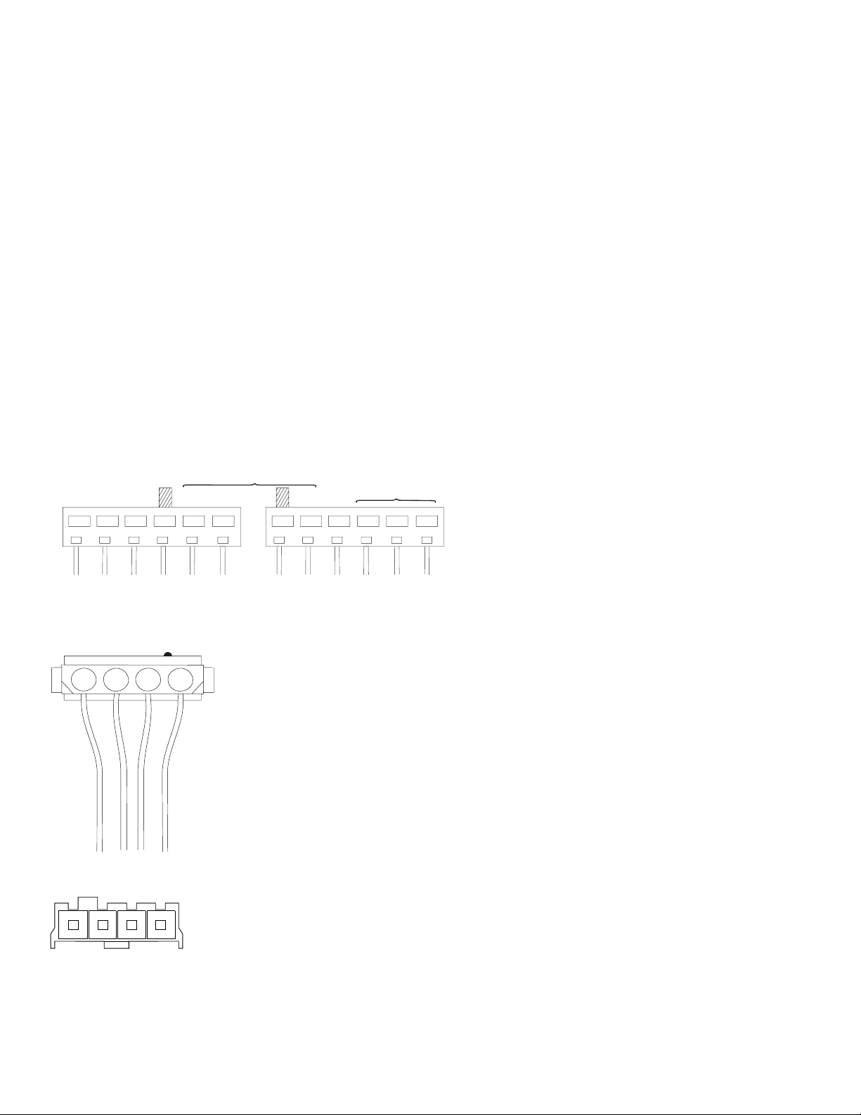
006 (continued)
– With the system powered off, check the Access Station cable for
continuity.
(continued)
GND
– -3.75 to -6.25 V dc
– +3.75 to 6.25 V dc
Pin
– -9 to -15 V dc
– PWR GOOD
– +3.75 to 6.25 V dc
– +9 to 15 V dc
1
Figure 2-1. System Board Power Supply Connectors (Bottom View)
5 V dc 12 V dc
4 1
Figure 2-2. Hard Drive or CD-ROM End of Power Cable
Pin
12
14
5 V dc 12 V dc
Figure 2-3. 3.5-In. Diskette Drive or Host Card End of Power Cable
(Step 006 continues)
2-36
Page 89

006 (continued)
ARE THE VOLTAGES CORRECT AND DOES THE FAN RUN?
Yes No
007
Replace the power supply.
008
– The power supply is working normally. (If you suspect the on/off switch
cable assembly, see Step 009.) If the fan continues to run when all
connectors are plugged back in, go to “Undetermined Problem” on
page 2-69. If the fan stops running when a drive connector is plugged
back in, go to “Factory-Installed Drive Devices” on page 2-47.
009
(From steps 003 and 008)
DOES THE SYSTEM UNIT FAIL TO SHUT OFF WHEN THE ON/OFF
SWITCH IS PRESSED?
Yes No
010
Go to Step 006 on page 2-35.
011
– You might have a failing on/off switch assembly.
– Disconnect the on/off switch cable assembly connector from the client
card and take an ohm reading.
DO YOU HAVE AN OHM READING WHEN THE SWITCH IS PRESSED
AND AN OPEN READING WHEN THE SWITCH IS RELEASED?
Yes No
012
– Replace the on/off switch assembly.
013
– Replace the system board.
Check Procedures 2-37
Page 90

Memory
Note: SIMMs must be set in the Setup Utility for correct parity setting.
When removing or installing a SIMM, run the Setup Utility (and set the date
and time) to clear any XX62 errors. See “POST Error Codes” on page 2-3.
001
– Insert the Diagnostics CD into the CD-ROM Drive.
– Power-off the system unit.
– Ensure all SIMMs are seated correctly.
– Power-on the system unit.
– Note any messages, error codes, or symptoms. Disregard 164 errors
(memory size).
DID YOU RECEIVE A 201 or 203 POST ERROR?
Yes No
002
DID YOU RECEIVE A 229 ERROR?
Yes No
003
Go to Step 006 on page 2-39.
004
Note: The system board has a pluggable cache module; continue
with the following step to determine whether to replace the
cache memory module or the system board.
– Replace the system board cache memory with a known good
module.
– Replace the system board.
005
– Follow the screen instructions to run the Memory tests.
– If you cannot run the memory test or the test does not find a problem, use
the following procedure to find the failure.
– Replace each SIMM, one at a time, with a known-good SIMM of the same
size and type. For the system board, replace the DIMM, if present, with a
known-good DIMM of the same size and type.
(Step 005 continues)
2-38
Page 91

005 (continued)
– If the problem goes away, the last SIMM replaced is defective. If all
SIMMs, and the DIMM on the Type A system board, have been replaced
and the problem remains, replace the system board.
006
(From step 003)
– Follow the screen instructions to run the Memory tests.
DID THE MEMORY TESTS COMPLETE WITHOUT AN ERROR?
Yes No
007
– Replace each SIMM, one at a time, with a known-good SIMM of the
same size and type. For the Type A system board, replace the
DIMM with a known-good DIMM of the same size and type.
– If the problem goes away, the last SIMM replaced is defective. If all
SIMMs, and the DIMM on the Type A system board, have been
replaced and the problem remains, replace the system board.
008
– The system memory is now functioning correctly. If you suspect an
intermittent problem, run the Memory test multiple times.
Check Procedures 2-39
Page 92

Keyboard
001
A failing mouse can show up as a keyboard failure.
– Power-off the system unit.
– Disconnect the mouse from Access Station.
– Power-on the system unit.
DID THE SYMPTOM REMAIN?
Yes No
002
Replace the failing mouse.
003
– Power-off the system unit and wait 10 seconds.
– Reinstall the mouse.
– Ensure the keyboard cable is fully inserted into the Access Station.
– Remove any foreign objects that may interfere with the mechanical
operation of the keybuttons.
– Power-on the system unit.
DID YOU RECEIVE A 3XX OR A 5803 POST ERROR?
Yes No
004
Go to “Start” on page 2-2.
005
– Power-off the system unit and wait 10 seconds.
– Disconnect the keyboard cable and the mouse cable from the Access
Station.
– Connect the keyboard cable and mouse cable to the system board.
– Power-on the system unit.
DID THE SYMPTOM CHANGE?
Yes No
006
Go to Step 008 on page 2-41.
007
2-40
Page 93

– Check the Access Station cable for continuity. See “Access Station” on
page 5-14 for pin locations.
– Replace the keyboard, Access Station host card, Access Station client
card, or Access Station cable.
– If the symptom remains, replace the system board.
008
– Disconnect the keyboard cable connector from the system board.
– Power-on the system unit.
– Check the voltage at the keyboard cable connector on the system board
as shown in Figure 2-4, after the POST.
Note: Measure voltages with respect to Ground (Pin 3).
Pin
1
2
3
4
5
6
Voltage (Vdc)
KBD Data (+5.0)
Not Used
Ground
+5.0
Clock (+5.0)
Not Used
6
4
2
5
3
1
Figure 2-4. Keyboard Connector Voltage Check
ARE THE VOLTAGES CORRECT?
Yes No
009
Replace the system board.
010
Replace the keyboard. If the symptom remains, replace the system board.
Check Procedures 2-41
Page 94

Mouse
Note: A sticking keybutton can cause the mouse to operate incorrectly. If
you suspect this, go to “Keyboard” on page 2-40.
001
– Insert the Diagnostics CD into the CD-ROM drive.
– Power-off the system unit.
– Make sure the mouse connector is connected to the proper port.
– Make sure the mouse ball turns freely.
– Power-on the system unit.
– Make a note of any error messages, then press Esc.
– Select Advanced Diagnostics from the Main Menu.
– Select Diagnostics from the Main Menu.
– Select Module Tests from the menu.
– Select Pointer Device from the menu.
– Follow the prompts and perform the test.
DO THE MOUSE DIAGNOSTIC TESTS RUN WITHOUT ERRORS?
Yes No
002
– If you receive any error
– If you receive an 8613 error, replace the system board.
003
– The system unit is operating normally.
– If the symptom remains, replace the mouse.
except
an 8613 error replace the mouse.
2-42
Page 95

Diagnostics Device Presence Test
001
DO ANY MESSAGES, ERROR CODES, BEEPS, OR SYMPTOMS
APPEAR?
Yes No
002
Go to Step 004.
003
Go to “Index of Symptoms, Messages, Error Codes, or Beeps” on page 2-9.
If directed here from the Index, go to Step 006.
004
(From step 002)
– Insert the Diagnostics CD into the CD-ROM drive.
– Power-off the system unit.
– Power-on the system unit, and check for the following responses:
1. One short beep
2. Main Menu screen
DID THE SYSTEM PRODUCE THE BEEP AND MAIN MENU SCREEN?
Yes No
005
– Go to “Index of Symptoms, Messages, Error Codes, or Beeps” on
page 2-9.
006
(From page 2-47)
(From step 003)
– Select Advanced Diagnostics on the menu.
– Select System Info on the menu.
– Select Hardware Config on the menu.
– Compare the Hardware Configuration Report screen with the actual
devices installed in the system unit.
Note: If necessary, remove the cover and visually compare the devices
installed in the system unit to those shown in the Hardware
Configuration Report.
Check Procedures 2-43
Page 96

DOES THE HARDWARE CONFIGURATION REPORT CORRECTLY
IDENTIFY THE DEVICES INSTALLED IN THE SYSTEM UNIT?
Yes No
007
– The Hardware Configuration Report shows only those devices
supported by the Diagnostics CD and only factory-installed devices
for the model you are servicing.
– If a device is missing from the list and is not factory installed, refer
to the service manual provided for that device. (Refer to the
Appendix B, “Model/Monitor Configurations and FRU Part Numbers”
on page B-1 to determine the factory-installed devices in the model
you are servicing.)
– If a factory-installed drive device or adapter card is not listed in the
Hardware Configuration Report, go to either “Diagnostics for
Factory-Installed Drive Devices Not Supported by the Diagnostics
CD” on page 2-50 or “Diagnostics for Factory-Installed Riser Card,
Sound Card, or Adapter Cards Not Supported by Diagnostics CD”
on page 2-53.
008
– Select Diagnostics Menu from the Main Menu.
– Select Easy Test Diagnostics from the Diagnostics Menu.
DOES THE EASY TEST FINISH WITHOUT ERROR CODES?
Yes No
(continued)
009
– If the last test stops and you cannot continue, first make sure all
switches, power connectors, cables, and jumpers are set correctly
and show the correct voltages and continuity.
– Make note of any messages, error codes, beeps, or new symptoms.
Go to “Index of Symptoms, Messages, Error Codes, or Beeps” on
page 2-9.
010
– The Easy Test Diagnostics did not detect a failure. If the system still
displays a failure:
Check all adapter card jumper settings.
Check all adapter card switch settings.
(Step 010 continues)
2-44
Page 97

010 (continued)
Check all adapter card cables and connectors for proper installation.
Make sure all of the above are set correctly and show the correct
voltages and continuity. Replace any defective cables or adapter
cards. See “Power Supply” on page 2-35 and “System Board Layout”
on page 5-2.
– Run the Easy Test Diagnostics test again.
– If an error or other symptom is displayed, go to “Index of Symptoms,
Messages, Error Codes, or Beeps” on page 2-9.
– If no error can be detected or the symptom is intermittent, go to
“Undetermined Problem” on page 2-69.
Check Procedures 2-45
Page 98

Access Station Drive Devices
Problems with the 3.5-in. diskette Drive, the CD-ROM drive, keyboard,
mouse, the On/Off switch, or the hard disk drive LED may be caused by the
Access Station.
Multiple error codes can also be the result of a loose Access Station cable
or defective host or client cards. If the system unit powers up with some or
all of the following POST error codes, the Access Station may be at fault.
1780 Hard disk error
5803 Keyboard error
5806 Diskette drive error
5862 Configuration error
5886 Pointing device error
If you receive multiple POST codes:
1. Check the installation of the Access Station cable on the host card.
2. Check the installation of the cable from pin J30 on the system board.
See “System Board Layout” on page 5-2 for more information.
3. Check the installation of the power connector from the power supply to
the host card.
4. Check the installation of the audio cable from the MWave card to the
host card.
If the problems persist see “Diagnostic Aids” on page 3-1 for more
information.
Use this check procedure to test any factory-installed drives.
2-46
Page 99

Factory-Installed Drive Devices
Use this check procedure to test any factory-installed drives.
Attention: The customer may have customized settings in the Setup Utility
(other than default settings) on the computer you are servicing. Running the
Setup Utility might alter those settings. Note the current settings and verify
that the customer settings are in place when service is complete.
Note: If you cannot access the hard disk drive or load a diskette from drive
A or load a CD from the CD-ROM drive, make sure the Setup Utility
has the startup sequence set with Diskette, CD-ROM, and Hard Disk
enabled.
Insert the Diagnostics CD in the CD-ROM drive. Refer to Step 006 on
page 2-43 to check Hardware Configuration.
If the number of diskette drives shown in the Installed Devices list is
not correct:
1. Check the installation of the drive ribbon cable to the system board.
Note: If the drive is installed the Access Station, check the drive ribbon
cable from the system board to the host card and from the drive
to the client card. Also check the Access Station cable.
2. Check the voltages to the diskette drive with the power on (see “Power
Supply” on page 2-35).
3. Check the installation of the Access Station cable on the system board.
4. Try to correct the drive setting in the (SETUP) option in the Setup Utility.
5. Run the “Diagnostics Device Presence Test” on page 2-43.
If you can correct the Installed Devices list, but cannot complete the
Diagnostics test for that device, replace FRUs, in the following order, until
the problem goes away:
1. Diskette drive
2. Diskette drive cable (if continuity check fails)
3. Access Station host card.
4. Access Station client card.
5. Access Station cable (Canada and Japan only)
6. Access Station
Note: The Access Station is replaced as a FRU in the U.S. only.
Canada models can order replacement parts for the Access
Station.
7. System board
Check Procedures 2-47
Page 100

If the number of hard disk drives or CD-ROM in the Installed Devices
list is not correct:
1. Check the installation of the drive ribbon cable from the host card to the
system board and the drive cable from the drive to the client card. Be
sure that Hard Disk Drive 1 and Hard Disk Drive 2 in the Setup Utility
are connected to the primary hard disk drive connector J5 on the
system board.
2. Check the hard disk drive jumper settings (see “Parts/Test Point
Locations” on page 5-1).
3. Check the voltages to the disk drive power connectors with the power
on (see “Power Supply” on page 2-35).
4. Try to correct the drive setting in the 3 (SETUP) option in the Setup
Utility.
5. Run the “Diagnostics Device Presence Test” on page 2-43 for hard disk
drives and CD-ROM drive.
6. Restart the system and check the Setup Utility.
7. In the Setup Utility, check that the correct drive size is set for the
flagged drive shown in the Installed Devices list.
If any drive is flagged as Not Installed, check the signal and
power cable for that drive.
If the first drive is flagged as Not Installed, replace the primary
drive.
If all drives are flagged as Not Installed, replace the primary drive.
If any drive (other than the first drive) is flagged as Not Installed,
replace that drive.
If the problem remains, check the continuity on the drive cable and
replace the cable if necessary. If that does not fix the problem,
replace the system board.
8. If an upgrade processor is installed, make sure that the processor speed
shown is correct.
Note: The CD-ROM must be the last device installed and jumpers set
correctly to be listed in the Setup Utility. See “Hard Disk Drive
Jumper Settings” on page 5-10 for factory-installed drive device
jumper settings and “CD-ROM Drive Jumper Settings” on
page 5-13.
Also ensure the CD-ROM cable is installed in connector J6 on
the system board.
For Aptiva models that come with an internal Zip drive, the
(continued)
2-48
 Loading...