

Page 1

IBM Cloud Object Storage System
Version 3.12.0
Accesser F5100 Appliance Manual
3401-A02/3403-A02
IBM
Page 2

Note
Before using this information and the product it supports, read the following information:
v The general information in Notices
v The information in Safety and environmental notices
v The information in the IBM Environmental Notices and User Guide (provided on a DVD)
This edition applies to IBM Cloud Object Storage System Accesser F5100 and is valid until replaced by new
editions.
© Copyright IBM Corporation 2016, 2017.
US Government Users Restricted Rights – Use, duplication or disclosure restricted by GSA ADP Schedule Contract
with IBM Corp.
Page 3

Contents
Figures ............... v
Tables ............... vii
Safety and environmental notices ... ix
Safety notices .............. ix
Environmental notices ........... xii
Declared noise emissions ........ xiii
Support information ......... xv
Chapter 1. Appliance safety precautions 1
Physical ................ 1
Electrical................ 1
Electronic components ........... 2
Chapter 2. Specifications and
requirements ............ 3
Appliance specifications .......... 3
Requirements .............. 3
Chapter 3. Install the appliance into a
rack ................ 5
Prepare for installation ........... 5
Appliance installation ........... 7
Chapter 4. Appliance physical interface 13
Front control panel ............ 13
Rear panel............... 14
Network interface ports .......... 15
Chapter 5. Field replaceable units ... 17
Replacement parts ............ 17
Replace external front components ...... 17
Replace external rear components ....... 18
Battery removal and installation ....... 19
Notices .............. 21
Trademarks .............. 23
Homologation statement .......... 23
© Copyright IBM Corp. 2016, 2017 iii
Page 4

iv IBM Cloud Object Storage System: Accesser F5100 Appliance Manual 3401-A02/3403-A02
Page 5

Figures
1. Rear of the appliance with the card slot
highlighted ............. 3
2. Identifying the sections of the rack rails ... 7
3. Remove the inner rails from both rail kits 7
4. Retracting the outer rail ......... 8
5. Attaching the sections of the rack inner rails 8
6. Aligning the outer rails with holes in rack post 9
7. Push outer rail into rack post ....... 9
8. Attach back of outer rail ........ 9
9. Final outer rail assembly and mounting 10
10. Push chassis into rack ......... 11
11. Rear of appliance .......... 11
12. Front of appliance .......... 11
13. Front panel buttons and LEDs for the
appliance ............. 13
14. Rear panel I/O ports for the appliance 14
15. LAN LED connection speed indicator .... 15
16. Removing a drive from the chassis ..... 18
17. Removing a PSU from the chassis ..... 18
18. Remove the battery .......... 19
19. Install the battery .......... 20
© Copyright IBM Corp. 2016, 2017 v
Page 6

vi IBM Cloud Object Storage System: Accesser F5100 Appliance Manual 3401-A02/3403-A02
Page 7

Tables
1. Declared noise emissions in accordance with
ISO 9296
2. Space and power requirements for the
appliance.............. 3
3. Operating and non-operating temperatures and
humidity for the appliance ........ 3
4. Cabling requirements for the appliance.... 4
(1,2,3)
............ xiii
5. Appliance location considerations ..... 5
6. Legend for front panel buttons and LEDs 13
7. Legend for rear panel I/O Ports for the
appliance ............. 15
8. LAN LED connection speed colors ..... 15
9. Power supply LED states ........ 15
10. Conditions indicated by drive carrier LEDs 16
© Copyright IBM Corp. 2016, 2017 vii
Page 8

viii IBM Cloud Object Storage System: Accesser F5100 Appliance Manual 3401-A02/3403-A02
Page 9

Safety and environmental notices
Review the safety notices, environmental notices, and electronic emission notices for IBM®Cloud Object
Storage System before you install and use the product.
Suitability for telecommunication environment - This product is not intended to connect directly or
indirectly by any means whatsoever to interfaces of public telecommunications networks.
Examples of a caution and a danger notice. Numbers in parentheses refer to message numbers in the IBM
Safety Notices publication G229-9054, which is included with your product.
CAUTION:
A caution notice indicates the presence of a hazard that has the potential of causing moderate or
minor personal injury. (C001)
DANGER
A danger notice indicates the presence of a hazard that has the potential of causing death or serious
personal injury. (D002)
Safety notices
Safety notices for this product.
Familiarize yourself with the IBM Safety Notices publication G229-9054, which is included with your
product.
© Copyright IBM Corp. 2016, 2017 ix
Page 10

DANGER: When working on or around the system, observe the following precautions:
Electrical voltage and current from power, telephone, and communication cables are hazardous. To
avoid a shock hazard:
• , connect power to this unit only with the IBM provided powerIf IBM supplied a power cord(s)
cord. Do not use the IBM provided power cord for any other product.
• Do not open or service any power supply assembly.
• Do not connect or disconnect any cables or perform installation, maintenance, or reconfiguration
of this product during an electrical storm.
• The product might be equipped with multiple power cords. To remove all hazardous voltages,
disconnect all power cords.
• Connect all power cords to a properly wired and grounded electrical outlet. Ensure that the outlet
supplies proper voltage and phase rotation according to the system rating plate.
• Connect any equipment that will be attached to this product to properly wired outlets.
• When possible, use one hand only to connect or disconnect signal cables.
• Never turn on any equipment when there is evidence of fire, water, or structural damage.
• Do not attempt to switch on power to the machine until all possible unsafe conditions are corrected.
• Assume that an electrical safety hazard is present. Perform all continuity, grounding, and power
checks specified during the subsystem installation procedures to ensure that the machine meets
safety requirements.
• Do not continue with the inspection if any unsafe conditions are present.
• Disconnect the attached power cords, telecommunications systems, networks, and modems before
you open the device covers, unless instructed otherwise in the installation and configuration
procedures.
• Connect and disconnect cables as described in the following procedures when installing, moving,
or opening covers on this product or attached devices.
To disconnect:
1. Turn off everything (unless instructed otherwise).
2. Remove the power cords from the outlets.
3. Remove the signal cables from the connectors.
4. Remove all cables from the devices.
To connect:
1. Turn off everything (unless instructed otherwise).
2. Attach all cables to the devices.
3. Attach the signal cables to the connectors.
4. Attach the power cords to the outlets.
5. Turn on the devices.
• Sharp edges, corners and joints may be present in and around the system. Use care when handling
equipment to avoid cuts, scrapes and pinching. (D005)
DANGER: Heavy equipment — personal injury or equipment damage might result if mishandled.
(D006)
x IBM Cloud Object Storage System: Accesser F5100 Appliance Manual 3401-A02/3403-A02
Page 11

DANGER: Professional movers are to be used for all relocation activities. Serious injury or death
may occur if systems are handled and moved incorrectly. (D008)
DANGER: Serious injury or death can occur if loaded lift tool falls over or if a heavy load falls off
the lift tool. Always completely lower the lift tool load plate and properly secure the load on the lift
tool before moving or using the lift tool to lift or move an object. (D010)
CAUTION:
T
The battery contains lithium. To avoid possible explosion, do not burn or charge the
battery.
Do not: hrow or immerse into water, heat to more than 100ºC (212ºF), repair or disassemble. (C003)
DANGER: Observe the following precautions when working on or around your IT rack system:
• Heavy equipment—personal injury or equipment damage might result if mishandled.
• Always lower the leveling pads on the rack cabinet.
• Always install stabilizer brackets on the rack cabinet.
• To avoid hazardous conditions due to uneven mechanical loading, always install the heaviest
devices in the bottom of the rack cabinet. Always install servers and optional devices starting
from the bottom of the rack cabinet.
• Rack-mounted devices are not to be used as shelves or work spaces. Do not place objects on top
of rack-mounted devices.
• Each rack cabinet might have more than one power cord. Be sure to disconnect all power cords in
the rack cabinet when directed to disconnect power during servicing.
• Connect all devices installed in a rack cabinet to power devices installed in the same rack cabinet.
Do not plug a power cord from a device installed in one rack cabinet into a power device
installed in a different rack cabinet.
• An electrical outlet that is not correctly wired could place hazardous voltage on the metal parts of
the system or the devices that attach to the system. It is the responsibility of the customer to
ensure that the outlet is correctly wired and grounded to prevent an electrical shock.
(R001 part 1 of 2)
Use the following general safety information for all rack mounted devices:
Safety and environmental notices xi
Page 12

CAUTION:
• Do not install a unit in a rack where the internal rack ambient temperatures will exceed the
manufacturer’s recommended ambient temperature for all your rack-mounted devices.
• Do not install a unit in a rack where the air flow is compromised. Ensure that air flow is not
blocked or reduced on any side, front or back of a unit used for air flow through the unit.
• Consideration should be given to the connection of the equipment to the supply circuit so that
overloading of the circuits does not compromise the supply wiring or overcurrent protection. To
provide the correct power connection to a rack, refer to the rating labels located on the equipment
in the rack to determine the total power requirement of the supply circuit.
• (For sliding drawers): Do not pull out or install any drawer or feature if the rack stabilizer
brackets are not attached to the rack. Do not pull out more than one drawer at a time. The rack
might become unstable if you pull out more than one drawer at a time.
• (For fixed drawers): This drawer is a fixed drawer and must not be moved for servicing unless
specified by the manufacturer. Attempting to move the drawer partially or completely out of the
rack might cause the rack to become unstable or cause the drawer to fall out of the rack.
(R001 part 2 of 2)
DANGER: Multiple power cords. The product might be equipped with multiple power cords. To
remove all hazardous voltages, disconnect all power cords. (L003)
Environmental notices
This information contains all of the environmental notices for IBM Systems products in English and other
languages.
xii IBM Cloud Object Storage System: Accesser F5100 Appliance Manual 3401-A02/3403-A02
Page 13

The IBM Systems Environmental Notices (http://ibm.co/1fBgWFI) information includes statements on
limitations, product information, product recycling and disposal, battery information, flat panel display,
refrigeration and water-cooling systems, external power supplies, and safety data sheets.
Declared noise emissions
Declared noise emissions in accordance with ISO 9296
Table 1. Declared noise emissions in accordance with ISO 9296
Declared A-Weighted
Sound Power Level,
Product description
Operating Idling Operating Idling
Models: A00, A01, A02, M01
7.2
@ 25 deg. C room ambient
Models: A00, A01, A02, M01
7.2
@ 35 deg. C room ambient
Models: A00, A01, A02, M01
6.6 6.2 49 45
@ 25 deg. C room ambient
Acoustical Doors Feature codes
FC EC07 = back FC EC08 = front
Models: A00, A01, A02, M01
6.6 6.6 49 49
@ 35 deg. C room ambient
(1,2,3)
L
(B)
WAd
(4)
(4)
6.8 56 52
(4)
7.2
(1, 2, 3)
Declared A-Weighted
Sound Pressure Level,
L
(dB)
pAm
56 56
Acoustical Doors Feature codes
FC EC07 = back FC EC08 = front
Notes:
1. Declared level L
is the upper-limit A-weighted sound power level; Declared level L
WAd
is the mean
pAm
A-weighted sound pressure level measured at the 1-meter bystander positions.
2. All measurements made in conformance with ISO 7779 and declared in conformance with ISO 9296.
3. B, dB, abbreviations for bels and decibels, respectively. 1 B = 10 dB.
4.
Note: Government regulations (such as those prescribed by OSHA or European Community Directives) may
govern noise level exposure in the workplace and may apply to you and your server installation. This IBM
system is available with an optional acoustical door feature that can help reduce the noise emitted from this
system. The actual sound pressure levels in your installation depend upon a variety of factors, including the
number of racks in the installation; the size, materials, and configuration of the room where you designate the
racks to be installed; the noise levels from other equipment; the room ambient temperature, and employees'
location in relation to the equipment. Further, compliance with such government regulations also depends upon
a variety of additional factors, including the duration of employees' exposure and whether employees wear
hearing protection. IBM recommends that you consult with qualified experts in this field to determine whether
you are in compliance with the applicable regulations.
Safety and environmental notices xiii
Page 14

xiv IBM Cloud Object Storage System: Accesser F5100 Appliance Manual 3401-A02/3403-A02
Page 15

Support information
For more information on the product or help with troubleshooting, contact IBM Support at
IBMCloudStorageSupport@us.ibm.com or visit the Directory of worldwide contacts.
© Copyright IBM Corp. 2016, 2017 xv
Page 16

xvi IBM Cloud Object Storage System: Accesser F5100 Appliance Manual 3401-A02/3403-A02
Page 17

Chapter 1. Appliance safety precautions
DANGER: An electrical outlet that is not correctly wired could place hazardous voltage on the
metal parts of the system or the devices that attach to the system. It is the responsibility of the
customer to ensure that the outlet is correctly wired and grounded to prevent an electrical shock.
(D004)
DANGER: Multiple power cords. The product might be equipped with multiple power cords. To
remove all hazardous voltages, disconnect all power cords. (L003)
Observe physical, electrical, and electronic component safety precautions.
Physical
Ensure that your equipment rack is placed in a dust-free, well-ventilated area close to an uninterruptible
power supply (UPS). Leave enough room behind and around the rack for services and sufficient airflow.
v Keep the area around the appliance clean and free of clutter.
v Place the appliance top cover and any appliance components that were removed away from the
appliance or on a table so that they do not accidentally get damaged.
v While you are working on the appliance, do not wear loose clothing such as neckties and unbuttoned
shirt sleeves. They can retain a charge even if you are wearing a wrist strap, or could be pulled into a
fan.
v After you access the inside of the appliance, close the appliance and secure it to the rack unit with the
retention screws after you ensure that all connections are made.
v Close the rack’s front door and all panels and components on the appliances when not servicing to
maintain proper cooling.
Electrical
Basic electrical safety precautions must be followed to protect yourself and the appliance:
v Do not work alone with high-voltage components.
v Be aware of the locations of the power switch on the appliance and the room’s emergency power-off
switch, disconnection switch, or electrical outlet. If an electrical accident occurs, quickly remove power
from the system.
© Copyright IBM Corp. 2016, 2017 1
Page 18

DANGER
A danger of explosion exists if the Onboard battery is installed upside down, which reverses its
polarities. This battery must be replaced only with the same or an equivalent type that is
recommended by the manufacturer. Dispose of used batteries according to the battery
manufacturer’s instructions.
Electronic components
Electrostatic discharge (ESD) is generated by two objects with different electrical charges when they come
into contact with each other. An ESD neutralizes this difference, which can damage electronic components
and printed circuit boards (PCBs). In general, the following measures are sufficient to neutralize this
difference before contact is made to protect equipment from ESD:
v Use a grounded wrist strap that is designed to prevent ESDs.
v Keep all components in their antistatic containers until ready for installation.
v Touch a grounded metal object before you remove any board from its antistatic container.
v Remove any jewelry or metal objects from your body. They are excellent metal conductors that can
create short circuits and harm you if they come into contact with printed circuit boards or areas where
power is present.
2 IBM Cloud Object Storage System: Accesser F5100 Appliance Manual 3401-A02/3403-A02
Page 19

Chapter 2. Specifications and requirements
Appliance specifications
v 2 x Intel Xeon E5-2683v3 processors
v 16 x 16 GB PC4-17000 2133 MHz ECC Registered RAM modules
v 1U server with 8 front-accessible 2.5" drive bays
v Six 4-cm internal fans
v 2 hot-swappable 750 W PSUs in 1+1 configuration
v 8 OS drives - High Endurance SSD
v Onboard IPMI
v 2 Onboard 1 Gbps network ports.
v 1 Onboard 1 Gbps dedicated IPMI network port.
Note: Extra Networking Option
The appliance can support another networking card to provide extra Ethernet ports. This port is found to
the right of center on the rear of the appliance, as shown in the following figure.
Figure 1. Rear of the appliance with the card slot highlighted
Requirements
Physical space and power
The appliance uses 100 - 240 V power.
Table 2. Space and power requirements for the appliance
Rack
Model
F5100 1 17.2 1.75 26.97 29.7 43.68 4.32 68.5 13.5 250 W
Units W (in) H (in) D (in)
Environmental conditions
Table 3. Operating and non-operating temperatures and humidity for the appliance
Environment Temperature (°C) Temperature (°F)
Operating 10–35 50–95 8–90%
Non-operating -40–70 -40–158 5–95%
Weight
(lbs) W (cm) H (cm) D (cm)
Humidity
(non-condensing)
Weight
(kg)
Power
(W)
max
© Copyright IBM Corp. 2016, 2017 3
Page 20

Cabling
Table 4. Cabling requirements for the appliance
Cable Type and Usage
Power Cords Use only the power cords that are supplied with the appliance. Do not use another type
of cord. Do not use extension cords. If more power cords are needed, contact IBM
Support.
1000BASE-T Copper
Cables
Optical Fiber Cables Use Intel based enhanced small form-factor pluggable (SFP+) transceivers only. Both
Direct Attach Copper
Cables
Use high-quality Category 5e or 5 (CAT5e, CAT5) copper cables.
short reach (SFP+ SR) and long reach (SFP+ LR) optics are supported. Optical fiber cable
specifications depend on the SFP+ module used. For more detail, refer to Intel
documentation on Modules and Cables.
Any SFP+ passive or active direct attach copper cable compliant with the SFF-8431 v4.1
and SFF-8472 v10.4 specifications is supported. For more information, see Intel
documentation on Modules and Cables.
4 IBM Cloud Object Storage System: Accesser F5100 Appliance Manual 3401-A02/3403-A02
Page 21

Chapter 3. Install the appliance into a rack
Many different racks are on the market, which means that the assembly procedure might differ slightly.
This rail fits a rack between 26.5" and 34.5" deep.
Prepare for installation
Assemble tools
A #2 Phillips screwdriver and a cage nut tool are needed to install and secure the rails to the appliance.
Wear a set of leather work gloves when you are racking the appliance. They help to grip the appliance
and to avoid injury from metal edges.
CAUTION:
Do not use of any sort of hammer to secure the rails on the appliance. A hammer might damage the
drives within the chassis and possibly void the warranty.
Choose a setup location
Decide on a suitable location for the rack unit that holds your appliance.
Table 5. Appliance location considerations
Factor Comments
Restricted access location Install this appliance in a physically secure, limited access location only, such as a
service closet or data center.
Clean environment Situate it in a clean, well-ventilated, dust-free area.
Ambient operating temperature If installed in a closed or multi-unit rack assembly, the ambient operating
temperature of the rack environment might be greater than the ambient
temperature of the room. Install the equipment in an environment compatible with
the maximum rated ambient temperature (TMRA) for the appliance.
Sufficient airflow Mount the equipment into a rack so that the amount of airflow that is needed for
safe operation is not compromised. Leave enough clearance in front of the rack to
open the front door completely (36 inches). Leave about 36 inches of clearance
behind the rack for sufficient airflow and ease in servicing.
Mechanical loading Mount the equipment into a rack so that a hazardous condition does not arise due
to uneven mechanical loading. Install heavier items into the bottom of the
equipment rack to keep the rack stable. Mount equipment in a rack evenly to
prevent a later hazard.
Circuit overloading Give consideration to the connection of the equipment to the power supply
circuitry and the effect that any possible overloading of circuits might have on
overcurrent protection and power supply wiring. Appropriate consideration of
equipment nameplate ratings should be used when addressing this concern.
Note: The maximum current draw is printed on a label on the appliance power
supplies. The system might draw more than 15 Amps at startup (inrush current).
Reliable ground A reliable ground must be maintained always. The rack itself must be grounded.
Give particular attention to the power supply connections other than the direct
connections to the branch circuit, such as the use of power strips.
Power supply Use a regulating uninterruptible power supply (UPS) to protect the appliance from
power surges and voltage spikes, and to keep your system operating in a power
failure.
© Copyright IBM Corp. 2016, 2017 5
Page 22

Table 5. Appliance location considerations (continued)
Factor Comments
Heat, electricity, and EMI Avoid areas where heat, electrical noise, and electromagnetic fields are generated.
Prepare the rack
1. Ensure that the leveling jacks on the bottom of the rack are fully extended to the floor with the full
weight of the rack on them.
v In single rack installations, attach stabilizers to the rack.
v In multiple rack installations, couple the racks together.
2. Check that the rack is stable before extending an appliance from the rack.
3. Extend only one appliance at a time. Extending two or more simultaneously can destabilize the rack.
4. Determine the placement of each appliance in the rack before you install the rails.
5. Install the heaviest appliances (usually the Slicestor®appliances) on the bottom of the rack first, and
then work upward.
Unpack and inspect the box and its contents
1. Inspect outside of box for damage.
2. Note if the box was damaged in any way.
3. Open the top of the box and inspect for damage.
4. Remove all of the components from the packaging and inspect for damage.
5. Arrange for assistance lifting or installing the appliance in a rack. Use a forklift or lift table to prevent
possible injury.
CAUTION:
To prevent personal injury and equipment damage, have someone assist you during the equipment
installation. If necessary, reduce the weight of the enclosure by removing the hard disk drives and
power supply units during installation.
When using the lifting straps, keep them even and at the same level always. Otherwise, the system
can slide to one side, and possibly out of the straps completely. Make sure that the rubberized
sides of the lifting straps are against the chassis metal.
6. If the appliance itself shows damage, file a damage claim with the carrier who delivered it.
In addition to the appliance, the box includes:
v Rail kits
v Cables
v Manual
Remove packing materials on and in the appliance
1. Remove the tape warning on the top of the chassis that says: "Remove tape and foam before racking
system."
2. Loosen the thumbscrews to either side of the faceplate for the appliance.
3. Open the faceplate.
4. Remove the packing foam from the inside of the faceplate.
5. Close the faceplate.
6. Tighten the thumbscrews.
6 IBM Cloud Object Storage System: Accesser F5100 Appliance Manual 3401-A02/3403-A02
Page 23

Appliance installation
Attention: Allow the enclosure assembly to acclimate to room temperature before installation. Store the
disk drives at room temperature for at least 2 hours before use.
Identify the sections of the rack rails
The box contains two rail kits. Each rail kit contains three sections, as shown in the following figure:
v The outer rail mounts to the front rack vertical post and rear rack vertical post.
v The middle rail allows the outer rail to extend or shorten to accommodate racks of different depths.
v The inner rail mounts on the side of the appliance and slides into the outer rail that is mounted on the
rack, if wanted.
Figure 2. Identifying the sections of the rack rails
Release the inner rail
Remove the inner rail from each rail kit, as shown in the following figure.
Figure 3. Remove the inner rails from both rail kits
1. Pull on the front release tab to unlock the inner rail from the rail kit.
2. Remove and set aside each inner rail.
Chapter 3. Install the appliance into a rack 7
Page 24

Retract the outer rail
After releasing and removing the inner rail, retract the outer rail to its shortest length, as shown in the
following figure.
Figure 4. Retracting the outer rail
Attach the inner rails to the appliance
1. Place the right inner rail on the right side of the appliance, making sure that the rail faces “outward”
in the proper orientation so that it slides into the right outer rail.
2. Make sure that the inner rail screw holes and tabs are properly aligned with the matching screw holes
and tab locators on the appliance.
3. Install the inner rail to the appliance by aligning the key holes on the rail with the studs on the side
of the appliance.
4. Slide the inner rail towards the front of the appliance to hold it in place.
5. Secure the rail to the appliance with the screws that are provided in the rail kit, as shown in the
following figure.
Figure 5. Attaching the sections of the rack inner rails
6. Repeat these steps for the left inner rail.
Install the outer rails
1. Measure the distance from the front rail to the rear rail of the rack.
2. Extend the left outer rail so that it fits snugly into the allotted distance.
8 IBM Cloud Object Storage System: Accesser F5100 Appliance Manual 3401-A02/3403-A02
Page 25

3. Adjust both the short and long brackets to the proper distance so that the rail can fit snugly into the
rack.
4. Align the front tabs of the outer rail with the holes in the rack post, as shown in the following figure.
Figure 6. Aligning the outer rails with holes in rack post
5. Push the outer rail into the rack post so that the tabs go through the rack post and hold the rail in
place, as shown in the following figure.
Figure 7. Push outer rail into rack post
6. Attach the back of the left outer rail to the rear rack post through a similar process, as shown in the
following figure.
Figure 8. Attach back of outer rail
7. Repeat these steps for the right outer rail.
The final assembly of both outer rails is shown in the following figure.
Chapter 3. Install the appliance into a rack 9
Page 26

Figure 9. Final outer rail assembly and mounting
Lock the rail tabs
Both chassis rails have a locking tab, which locks the appliance in place when:
v Installed and pushed fully into the rack.
v Extended fully from the rack so it does not come out of the rack when pulled out for service.
Install the appliance into the rack
Attach the inner rails to the appliance chassis and the outer rails to the rack.
CAUTION:
When you are ready to install the appliance in the rack, you might need a lifting device. Alternatively,
use 2 - 4 individuals to place the appliance in position and begin inserting it into the rack rails.
To install the appliance into the rack, do the following steps:
1. Line up the rear of the chassis rails with the front of the rack rails.
2. Slide the chassis rails into the rack rails, keeping the pressure even on both sides, as shown in the
following figure. You might have to depress the locking tabs when inserting. When the appliance is
pushed completely into the rack, you can hear the locking tabs click into the locked position.
10 IBM Cloud Object Storage System: Accesser F5100 Appliance Manual 3401-A02/3403-A02
Page 27

Figure 10. Push chassis into rack
3. Secure the chassis to the rails with the captive M6 thumbscrews on the server.
Cable the appliance
1. On the rear panel, connect the C13 end of the power cables to the C14 inlets in the PSU, as shown in
the following figure.
Figure 11. Rear of appliance
2. The Ethernet connections are located just to the left of the center of the appliance and are next to each
other. Connect a standard Ethernet cable from the left Ethernet port.
3. Press the power button that is on the top far right corner of the appliance front panel when the bezel
is unscrewed and flipped down.
4. To ensure that the power is on, verify that the power and network link lights are lit and listen for
running fans, as shown in the following figure.
Figure 12. Front of appliance
Chapter 3. Install the appliance into a rack 11
Page 28

12 IBM Cloud Object Storage System: Accesser F5100 Appliance Manual 3401-A02/3403-A02
Page 29

Chapter 4. Appliance physical interface
The physical interface for the appliance consists of buttons and LEDs on the front panel and ports and
LEDs on the back panel.
Front control panel
The power status and the hard disk drive and network activity of the appliance can be read from its front
control panel, as shown in the following figure.
Figure 13. Front panel buttons and LEDs for the appliance
Table 6. Legend for front panel buttons and LEDs
Number Description
1 System health LED
2 Disk activity LED
3 Network link activity LED
4 Unit identification button/LED
5 Power button/LED
6 Non-maskable interrupt (NMI) button
7 Unused
8 Individual disk activity LED (green)
9 Individual disk status LED (blue/amber)
10 Disk drive 0
11 Disk drive 1
12 Disk drive 2
13 Disk drive 3
14 Disk drive 4
15 Disk drive 5
16 Disk drive 6
17 Disk drive 7
18 Asset tag (a pullout mylar tag for customer use)
© Copyright IBM Corp. 2016, 2017 13
Page 30

Table 6. Legend for front panel buttons and LEDs (continued)
Number Description
19 Rack mount screw (2)
Physical buttons
The appliance includes three push-buttons on the front panel:
NMI Issues a non-maskable interrupt to the server.
UID Facilitates finding a system in a rack that is viewed from the front. On the front panel, the LED is
on the button. Similarly, a functioning UID button/LED is on the back panel.
Power Applies or removes power from the power supply to the appliance. Powering down the
appliance removes the main power, but supplies stand-by power. The appliance must be
unplugged before servicing.
LEDs
The control panel has five LEDs to provide critical information for different components:
Disk activity
One LED serves to indicate activity for any of the front-mount hard disk drives. When the green
light is on or flashing, the hard disk is being accessed.
Unit identification LED (UID)
This LED facilitates finding a system in a rack that is viewed from the front. On the front panel,
the LED is on the button. Similarly, a functioning UID button/LED is on the back panel.
Power LED
Power supplied to PSUs; should be lit to indicate that power is applied to the server.
LAN active
When the green light is on, at least one of the LAN interfaces is active.
System Health
When the light is green, the system is working correctly. When the light is amber, a problem is
detected with system hardware. When the light is off, the disk drive is operational.
Rear panel
The rear panel contains I/O ports.
I/O ports
The I/O ports are color coded per the PC 99 specification. The locations of the various I/O ports are
shown in the following figure.
Figure 14. Rear panel I/O ports for the appliance
14 IBM Cloud Object Storage System: Accesser F5100 Appliance Manual 3401-A02/3403-A02
Page 31

Table 7. Legend for rear panel I/O Ports for the appliance
Number Description
1 Unused
2 PCIe card slot (on riser card)
3 10 GbE NIC card
4 Power supply 1
5 Power supply 2
6 UID button/LED
7 1 GbE RJ45 ports (2)
8 10/100 Mbit/s management port
9 DB-15 video connector
10 USB 2.0 ports (2)
Network interface ports
1 Gbps LAN LEDs
The LAN ports have two LEDs. One LED indicates activity when blinking. The other LED can be green,
amber or off to indicate the speed of the connection, as shown in the following figure. See the following
table for the functions associated with the connection speed LED.
Figure 15. LAN LED connection speed indicator
Table 8. LAN LED connection speed colors
Color Speed
Off No connection or 10 Mbps
Green 100 Mbps
Amber 1 Gbps
Intelligent Platform Management Interface (IPMI)
This network port allows remote administration of hardware. For a detailed description of IPMI, refer to
the following Intel documentation:
http://www.intel.com/content/www/us/en/servers/ipmi/ipmi-home.html
Power supplies
Each power supply includes one LED with three states in the rear.
Table 9. Power supply LED states
LED state Description
Solid green System on
Chapter 4. Appliance physical interface 15
Page 32

Table 9. Power supply LED states (continued)
LED state Description
Solid amber System plugged in and turned off or the appliance is off but in an
abnormal state
Blinking Amber Internal temperature reached 63°C. The appliance automatically
powers down when PSU temperature reaches 70°C and restarts when
the PSU temperature drops below 60°C.
Hard drive carrier
Each drive carrier has one LED with two states.
Table 10. Conditions indicated by drive carrier LEDs
Condition LED color
Drive activity Green
Drive failure Red
16 IBM Cloud Object Storage System: Accesser F5100 Appliance Manual 3401-A02/3403-A02
Page 33

Chapter 5. Field replaceable units
A number of components can be replaced in the field.
Replacement parts
Contact IBM Support for replacement parts for the appliance.
The following customer serviceable replacement parts are available:
v 4×8 GB Memory Modules
v Power Supply Module
v Operating System Drive
The following customer serviceable upgrades are available:
v SFP+/QSFP optical modules
See the Field Replaceable Units Reference Guide for a complete list of available parts and drives.
Replace external front components
Check the status of the operating system/database drives
The operating system and database for the appliance are stored on a RAID-1 disk set. When one drive in
this set is replaced, it rebuilds automatically. Check on the status of the RAID rebuild by using the
Manager Web Interface:
1. Check the Device Health of the Manager from the Monitor page.
2. Click Devices from the list on the left side of the page.
3. Click Manager.
4. Click a specific Manager device.
5. Check the list of drives under Summary of device health.
v If the drive was inserted correctly, the following message is displayed:
All drives are online.
6. Check the Event Console for the status of the RAID repair.
v If the drive in the RAID array is in repairing itself, the following message is displayed:
The local drive in bay bay_id is repairing.
v If the drive in the RAID array is successfully repaired, the following message is displayed:
The local drive in bay bay_id is repaired.
v If the drive in the RAID array is running correctly, this event shows:
Local drive array has been repaired.
Replace the operating system/database drives
1. Press the release button on the drive carrier. This action extends the carrier handle, as shown in the
following figure.
© Copyright IBM Corp. 2016, 2017 17
Page 34
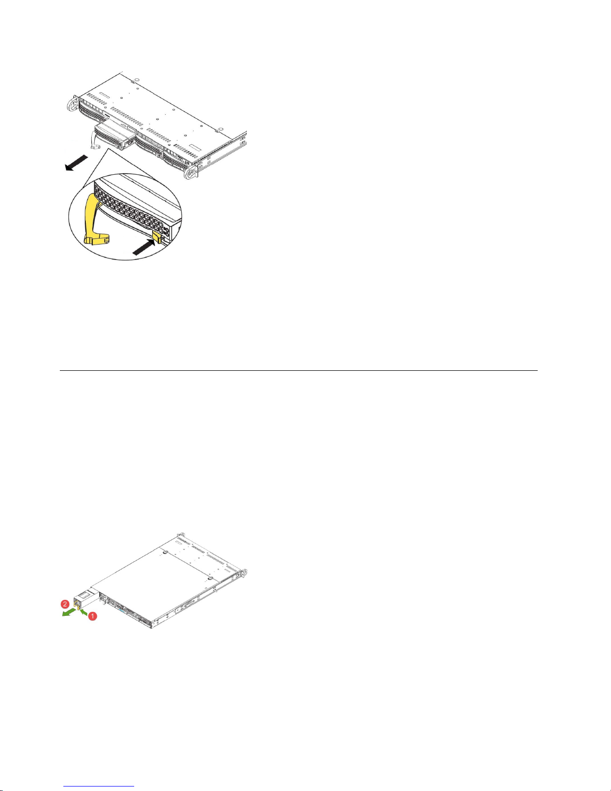
Figure 16. Removing a drive from the chassis
Note: The operating system drives are the two at the left. The preceding figure makes the extraction
of the drive easier to see and is only for illustration purposes.
2. Pull the drive carrier out of the chassis by using the handle.
3. Insert the new OS drive into the open slot in the front of the appliance.
4. Contact IBM Support to issue OS drive recovery.
Replace external rear components
Replace a power supply unit
If either of the two power supply units (PSU) fails, the other unit takes the full load and the system can
continue operation without interruption. The Universal Information LED on the control panel flashes
slowly until the failed unit is replaced.
The PSUs can be replaced without powering down the appliance. The redundant feature keeps the
appliance active while the failed PSU is replaced.
1. Push the release tab on the rear of the PSU, as shown in the following figure.
Figure 17. Removing a PSU from the chassis
2. Pull the PSU out using the provided handle. (The PSU wiring is designed to detach automatically
when the PSU is pulled from the chassis).
3. Replace the failed PSU with another PSU.
4. Push the new PSU into the power bay until you hear a click.
18 IBM Cloud Object Storage System: Accesser F5100 Appliance Manual 3401-A02/3403-A02
Page 35

Install an SFP+ / QSFP optical module
1. Log in to the device as localadmin.
2. At the command prompt, type poweroff.
3. Remove the SFP+ / QSFP module from the packaging.
4. Remove the black plastic protective cap from the optical side of the module.
5. Insert the module into the network card until it clicks into place.
6. Insert the fiber optic cable into the SFP+ / QSFP module.
7. Restart system and configure the network interface. For more information, see the Appliance
Configuration Guide.
Battery removal and installation
Battery removal
To remove the Onboard battery, follow these steps:
1. Power off your system and unplug your power cable.
2. Locate the Onboard battery, as shown in the figure below.
3. Using a tool such as a pen or a small screwdriver, push the battery lock outwards to unlock it. When
unlocked, the battery pops out from the holder.
4. Remove the battery, as shown in the following figure.
Figure 18. Remove the battery
CAUTION:
Handle used batteries carefully. Do not damage the battery in any way; a damaged battery can release
hazardous materials into the environment. Do not discard a used battery in the garbage or a public
landfill. Refer to the IBM Systems Environmental Notices for battery disposal guidelines.
Battery installation
To install an Onboard battery, follow these steps:
1. Identify the battery’s polarity. The positive (+) side must be facing up.
2. Insert the battery into the battery holder. Push it down until you hear a click to ensure that the
battery is securely locked, as shown in the following figure.
Chapter 5. Field replaceable units 19
Page 36

Figure 19. Install the battery
CAUTION:
Be sure to replace the battery with the same type only.
20 IBM Cloud Object Storage System: Accesser F5100 Appliance Manual 3401-A02/3403-A02
Page 37

Notices
This information was developed for products and services offered in the US. This material might be
available from IBM in other languages. However, you may be required to own a copy of the product or
product version in that language in order to access it.
IBM may not offer the products, services, or features discussed in this document in other countries.
Consult your local IBM representative for information on the products and services currently available in
your area. Any reference to an IBM product, program, or service is not intended to state or imply that
only that IBM product, program, or service may be used. Any functionally equivalent product, program,
or service that does not infringe any IBM intellectual property right may be used instead. However, it is
the user's responsibility to evaluate and verify the operation of any non-IBM product, program, or
service.
IBM may have patents or pending patent applications covering subject matter described in this
document. The furnishing of this document does not grant you any license to these patents. You can send
license inquiries, in writing, to:
IBM Director of Licensing
IBM Corporation
North Castle Drive
Armonk, NY 10504-1785
U.S.A.
For license inquiries regarding double-byte character set (DBCS) information, contact the IBM Intellectual
Property Department in your country or send inquiries, in writing, to:
Intellectual Property Licensing
Legal and Intellectual Property Law
IBM Japan, Ltd.
19-21, Nihonbashi-Hakozakicho, Chuo-ku
Tokyo 103-8510, Japan
INTERNATIONAL BUSINESS MACHINES CORPORATION PROVIDES THIS PUBLICATION "AS IS"
WITHOUT WARRANTY OF ANY KIND, EITHER EXPRESS OR IMPLIED, INCLUDING, BUT NOT
LIMITED TO, THE IMPLIED WARRANTIES OF NON-INFRINGEMENT, MERCHANTABILITY OR
FITNESS FOR A PARTICULAR PURPOSE. Some jurisdictions do not allow disclaimer of express or
implied warranties in certain transactions, therefore, this statement may not apply to you.
This information could include technical inaccuracies or typographical errors. Changes are periodically
made to the information herein; these changes will be incorporated in new editions of the publication.
IBM may make improvements and/or changes in the product(s) and/or the program(s) described in this
publication at any time without notice.
Any references in this information to non-IBM websites are provided for convenience only and do not in
any manner serve as an endorsement of those websites. The materials at those websites are not part of
the materials for this IBM product and use of those websites is at your own risk.
IBM may use or distribute any of the information you provide in any way it believes appropriate without
incurring any obligation to you.
© Copyright IBM Corp. 2016, 2017 21
Page 38

Licensees of this program who wish to have information about it for the purpose of enabling: (i) the
exchange of information between independently created programs and other programs (including this
one) and (ii) the mutual use of the information which has been exchanged, should contact:
IBM Director of Licensing
IBM Corporation
North Castle Drive, MD-NC119
Armonk, NY 10504-1785
US
Such information may be available, subject to appropriate terms and conditions, including in some cases,
payment of a fee.
The licensed program described in this document and all licensed material available for it are provided
by IBM under terms of the IBM Customer Agreement, IBM International Program License Agreement or
any equivalent agreement between us.
The performance data discussed herein is presented as derived under specific operating conditions.
Actual results may vary.
Information concerning non-IBM products was obtained from the suppliers of those products, their
published announcements or other publicly available sources. IBM has not tested those products and
cannot confirm the accuracy of performance, compatibility or any other claims related to non-IBM
products. Questions on the capabilities of non-IBM products should be addressed to the suppliers of
those products.
Statements regarding IBM's future direction or intent are subject to change or withdrawal without notice,
and represent goals and objectives only.
All IBM prices shown are IBM's suggested retail prices, are current and are subject to change without
notice. Dealer prices may vary.
This information is for planning purposes only. The information herein is subject to change before the
products described become available.
This information contains examples of data and reports used in daily business operations. To illustrate
them as completely as possible, the examples include the names of individuals, companies, brands, and
products. All of these names are fictitious and any similarity to the names and addresses used by an
actual business enterprise is entirely coincidental.
COPYRIGHT LICENSE:
This information contains sample application programs in source language, which illustrate programming
techniques on various operating platforms. You may copy, modify, and distribute these sample programs
in any form without payment to IBM, for the purposes of developing, using, marketing or distributing
application programs conforming to the application programming interface for the operating platform for
which the sample programs are written. These examples have not been thoroughly tested under all
conditions. IBM, therefore, cannot guarantee or imply reliability, serviceability, or function of these
programs. The sample programs are provided "AS IS", without warranty of any kind. IBM shall not be
liable for any damages arising out of your use of the sample programs.
If you are viewing this information softcopy, the photographs and color illustrations may not appear.
22 IBM Cloud Object Storage System: Accesser F5100 Appliance Manual 3401-A02/3403-A02
Page 39

Trademarks
IBM, the IBM logo, and ibm.com®are trademarks or registered trademarks of International Business
Machines Corp., registered in many jurisdictions worldwide. Other product and service names might be
trademarks of IBM or other companies. A current list of IBM trademarks is available on the web at
Copyright and trademark information at www.ibm.com/legal/copytrade.shtml.
Accesser®, Cleversafe®, ClevOS™, Dispersed Storage®, dsNet®, IBM Cloud Object Storage Accesser®, IBM
Cloud Object Storage Dedicated™, IBM Cloud Object Storage Insight™, IBM Cloud Object Storage
Manager™, IBM Cloud Object Storage Slicestor®, IBM Cloud Object Storage Standard™, IBM Cloud Object
Storage System™, IBM Cloud Object Storage Vault™, SecureSlice™, and Slicestor®are trademarks or
registered trademarks of Cleversafe, an IBM Company and/or International Business Machines Corp.
Other product and service names might be trademarks of IBM or other companies.
Homologation statement
This product may not be certified in your country for connection by any means whatsoever to interfaces
of public telecommunications networks. Further certification may be required by law prior to making any
such connection. Contact an IBM representative or reseller for any questions.
Notices 23
Page 40

24 IBM Cloud Object Storage System: Accesser F5100 Appliance Manual 3401-A02/3403-A02
Page 41

Page 42

IBM®
Printed in USA
 Loading...